Embed Size (px)
Citation preview
USE ONLY HAYWARD GENUINE REPLACEMENT PARTS
Hayward Pool Products (Australia) Pty Ltd.Melbourne-Sydney-Brisbane-Perth
Email: [email protected] | Website: www.hayward-pool.com.auPO Box 4384 | Dandenong South VIC 3164
ABN 66 083 413 414Sales Contact Ph: 1300POOLS1 Fax: 1300POOLS2
SAVE THIS INSTRUCTION MANUAL
30-LITINSD010RB
For the AquaRite™+
To prevent potential injury and to avoid unnecessary service calls, read this manual carefully and completely.
Wi-Fi Network Upgrade Kit
Owner’s Manual
Page 2 USE ONLY HAYWARD® GENUINE REPLACEMENT PARTS
WARNING: Electrical hazard. Failure to comply with these instructions can result in
serious injuries or death.THE EQUIPMENT IS INTENDED TO BE USED ONLY ON
PERMANENTLY CONSTRUCTED POOLS AND SPAS
WARNING – Disconnect/isolate the equipment from the electricity supply before any installation/service/repair.
WARNING – All electrical wiring must be performed by a qualified and licensed electrical contractor in accordance with all Local/State/Federal Government electrical regulations and the latest edition of the AS/NZS 3000 Wiring Rules.
WARNING – Ensure that the device is plugged into a power outlet that is protected against short-circuits. The device must also be powered via an isolating transformer or through a residual current device (RCD) with a fixed residual operating current not exceeding 30mA.
WARNING – Check that the supply voltage required by the product corresponds to the voltage of the distribution network.
WARNING – To reduce the risk of electric shock, do not use an extension cord to connect the device to the mains. Use a suitably rated GPO as per the standard AS/NZS 3000.
WARNING – Chemicals can cause internal and external burns. To avoid death, serious injury and/or damage to equipment, wear personal protective equipment (gloves, goggles, mask, etc.) when servicing or maintaining this device. This device must be installed in an adequately ventilated place when equipped with the chemical feed options.
WARNING – Carefully read the instructions that appear in this manual and on the device. Failure to comply with the instructions can cause injuries. This document must be given to the pool owner, who should keep it in a safe place.
WARNING – The appliance can be used by children aged from 8 years and above and persons with reduced physical, sensory or mental capabilities, or lack of experience and knowledge, if they have been given supervision or instruction concerning use of the appliance in a safe way and understand the hazards involved.
WARNING – Use only genuine Hayward replacement parts.
WARNING – If the power supply cord is damaged the device must not be used. The power supply cord must be replaced by the manufacturer or similarly qualified persons to avoid any danger.
Page 3USE ONLY HAYWARD® GENUINE REPLACEMENT PARTS
INTRODUCTIONThe Wi-Fi Network Upgrade Kit is an optional accessory to the Hayward AquaRite+ Chlorinator. The Wi-Fi module connects the AquaRite+ to the Vista Pool server and app which allows you to remotely control the AquaRite+ via the Internet.
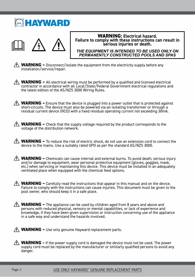
COMPONENTS
Wi-Fi Module Cable TieCable Gland
Wi-Fi Network Upgrade Kit
INSTALLATIONOutlineThe Wi-Fi Module must be installed on a wall in a dry (out of the rain), temperate and ventilated location, and must be able to communicate with the Wi-Fi network at the premises where it is installed. A field survey with a mobile telephone can be conducted to see if the premises Wi-Fi signal is strong enough to connect to.
The Wi-Fi range is approximate 50 metres line of site with no obstacles in between the Wi-Fi Module and the router/modem. Having walls, fences, buildings, etc in between the Wi-Fi Module and the router/modem will also impede the ability to hold a reliable signal and will dramatically reduce the range of the unit.The connection cable that comes in the kit is 9.5 metres long and and can be shortened by following the instructions on page 5 of this manual. Disconnect the power supply to the AquaRite+ unit before connecting the module. Below is an outline of the installation process, with detailed instructions on the pages following.
» Remove the Dead Front Panel » Release the cable from the Wi-Fi Module » Plug the Wi-Fi Module connector into the RF / Wi-Fi terminal on the AquaRite+ PCB » Reconnect and reassemble the Wi-Fi Module » Secure cable to AquaRite+ with Cable Gland » Mount on flat surface

Page 4 USE ONLY HAYWARD® GENUINE REPLACEMENT PARTS
INSTALLATION
Removing the Dead Front PanelIn order to connect the Wi-Fi Module to the AquaRite+ circuitry, the Dead Front Panel needs to be carefully removed. Follow the instructions below to avoid damaging the device and/or its casing.
Caution - Risk of Electric Shock. Ensure that the unit has been disconnected from all power supplies before removing the Display and Dead Front Panel. Only a suitably qualified person should remove the Dead Front Panel in accordance with Local/State/Federal Government regulations and the latest edition of the AS/NZS 3000 Wiring Rules.
Lift Out Interactive Display Module:Remove display module from its compartment. Use the grooves on either side to pry it out by hand. Take care to not use excessive force as the module is still wired to the PCB at this stage.
Detach Interactive Display Module:Turn over the display module and remove the wired plug from the port on the back of the unit. Store the Display Module where it will not get damaged until it is re-installed.
Unscrew Dead Front Panel:Remove the six (6) screws fastening the panel to the unit. Once all loose, lift the panel off the unit to access the PCB.
Display Module
Pull
Unscrew UnscrewPCB
1.
3.
5.
2.
4.
6.
Lift Lift

Page 5USE ONLY HAYWARD® GENUINE REPLACEMENT PARTS
INSTALLATIONAccessing the Wi-Fi Module WiringThe Wi-Fi Module needs to be opened so that the cable can be physically connected to the AquaRite+ and trimmed to length.
Cable Gland InstallationIn order to ensure watertight wire connections to the PCB through the AquaRite+ housing, wire cables are to be secured with the black cable glands supplied. With the Wi-Fi cable plugged in, follow the instructions below to thread the free end of the cable through the housing for it to be re-wired to the Wi-Fi module.
1. Unscrew the backing plate and remove to reveal the module’s circuitry. Put the backing and screws aside.
2. Release the 4 wires by loosening the terminal screws.
3. Pull the cable through to allow enough room to be able to slide the cable tie off. If the tie is too tight, carefully remove with side cutters.
4. Discard the old cable tie and pull the cable out through hole. Keep the circuitry exposed, as the cable will need to be rewired back into place.
Unscrew
Unscrew Cable Tie
Terminal
3. Push the cable gland into the hole whilst simultaneously rotating to screw the nut on to the thread.Tighten gland with a spanner whilst still holding the nut to secure the gland in place.
4. Pull the cord through the gland. Be sure to leave enough cable for the plug to reach the Wi-Fi input. Secure and seal the cord in place by tightening the domed cap with a spanner until firm.
Tighten
Tighten
2. Insert the cable into the flat/thread end of the gland and pull through.
Cable
Gland
1. Hold the nut against the hole on the inside of the casing. Push the cable through the nut and hole, from the inside of the unit.
Nut
CasingInside the Unit
Outside the Unit
Inside the Unit
Outside the Unit
Note: Use the gland location holes in the bottom of the unit before the sides to ensure all cables are pointing downward.
Page 6 USE ONLY HAYWARD® GENUINE REPLACEMENT PARTS
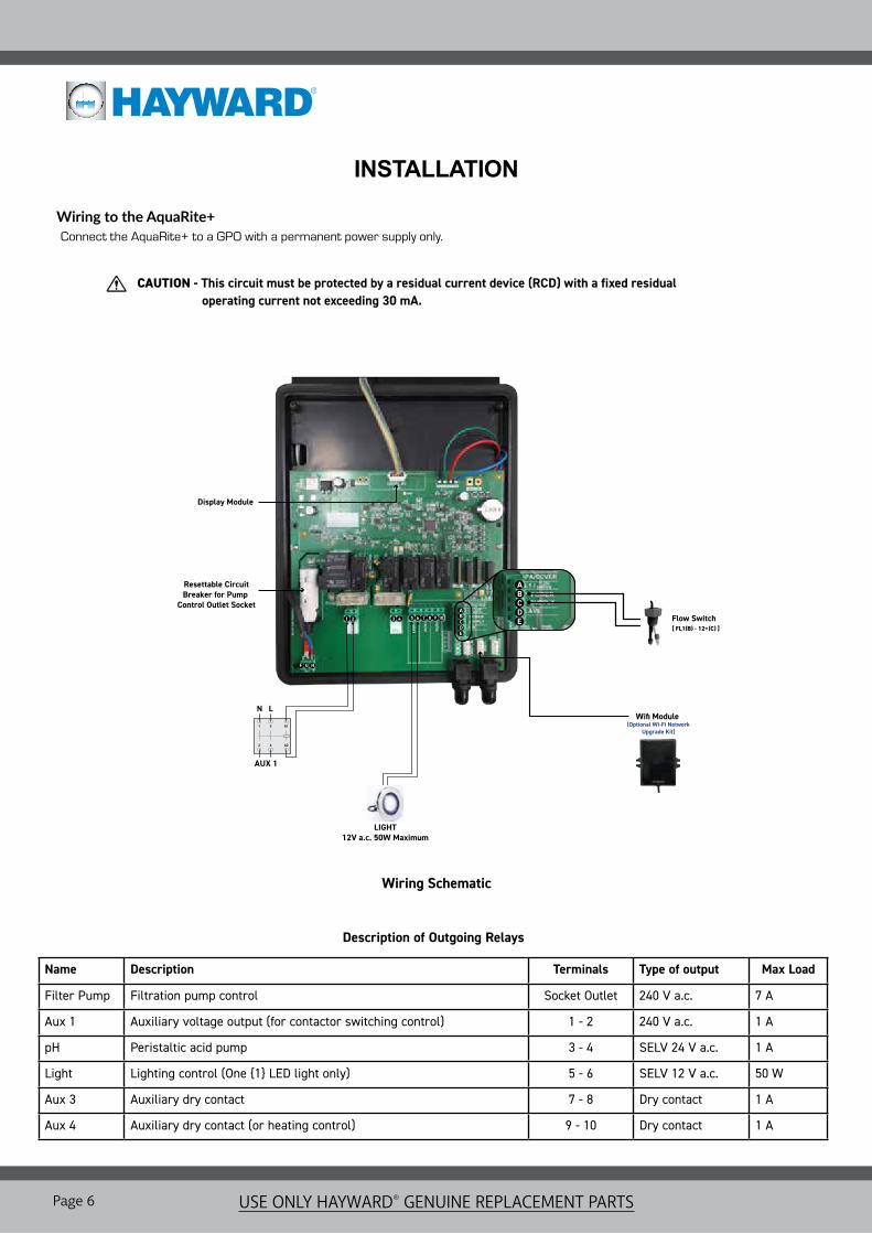
Wiring to the AquaRite+ Connect the AquaRite+ to a GPO with a permanent power supply only.
INSTALLATION
Description of Outgoing Relays
Name Description Terminals Type of output Max Load
Filter Pump Filtration pump control Socket Outlet 240 V a.c. 7 A
Aux 1 Auxiliary voltage output (for contactor switching control) 1 - 2 240 V a.c. 1 A
pH Peristaltic acid pump 3 - 4 SELV 24 V a.c. 1 A
Light Lighting control (One {1} LED light only) 5 - 6 SELV 12 V a.c. 50 W
Aux 3 Auxiliary dry contact 7 - 8 Dry contact 1 A
Aux 4 Auxiliary dry contact (or heating control) 9 - 10 Dry contact 1 A
CAUTION - This circuit must be protected by a residual current device (RCD) with a fixed residual _________operating current not exceeding 30 mA.
Wifi Module (Optional Wi-Fi Network
Upgrade Kit)
Resettable CircuitBreaker for Pump
Control Outlet Socket
Display Module
1 2 3 4 6 7 108 95ABCDE
ABCDE
F G
LIGHT12V a.c. 50W Maximum
H
AUX 1
1
2
3
4
A1
A2
N L
Flow Switch[ FL1(B) - 12+(C) ]
Wiring Schematic
Page 7USE ONLY HAYWARD® GENUINE REPLACEMENT PARTS
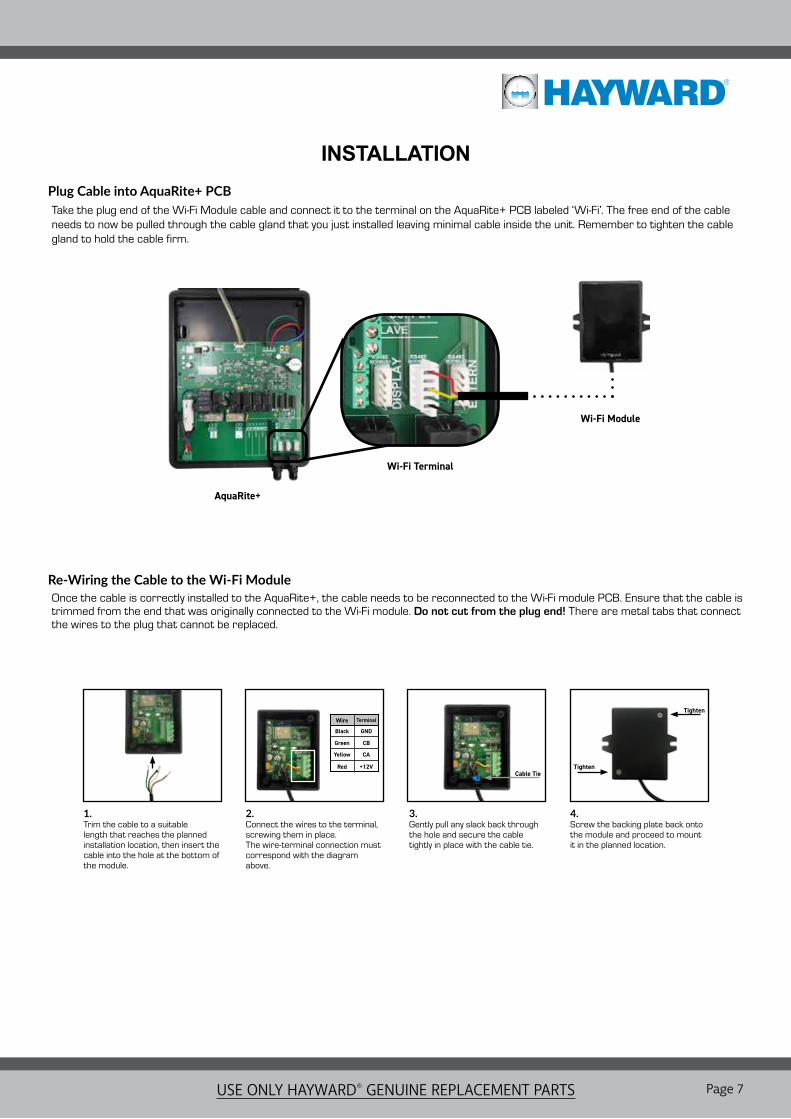
INSTALLATIONPlug Cable into AquaRite+ PCBTake the plug end of the Wi-Fi Module cable and connect it to the terminal on the AquaRite+ PCB labeled ‘Wi-Fi’. The free end of the cable needs to now be pulled through the cable gland that you just installed leaving minimal cable inside the unit. Remember to tighten the cable gland to hold the cable firm.
Re-Wiring the Cable to the Wi-Fi ModuleOnce the cable is correctly installed to the AquaRite+, the cable needs to be reconnected to the Wi-Fi module PCB. Ensure that the cable is trimmed from the end that was originally connected to the Wi-Fi module. Do not cut from the plug end! There are metal tabs that connect the wires to the plug that cannot be replaced.
1. Trim the cable to a suitable length that reaches the planned installation location, then insert the cable into the hole at the bottom of the module.
2. Connect the wires to the terminal, screwing them in place. The wire-terminal connection must correspond with the diagram above.
3. Gently pull any slack back through the hole and secure the cable tightly in place with the cable tie.
4. Screw the backing plate back onto the module and proceed to mount it in the planned location.
Tighten
Tighten
Cable Tie
TerminalWire
Black
Green
Yellow
Red +12V
CA
CB
GND
AquaRite+
Wi-Fi Terminal
Wi-Fi Module

Page 8 USE ONLY HAYWARD® GENUINE REPLACEMENT PARTS
OPERATION
Plugging in the Wi-Fi cable automatically allows the AquaRite+ to discover it and open menu options within the interface. The existing set up instructions detailed in the AquaRite+ Owner’s Manual still stand, just more settings options appear that are specific to the Wi-Fi Kit function. Below are instructions on configuring the Wi-Fi settings now available.
Home Screen Configuration
Establishing the Wi-Fi Module Connection
1 2 3 4 5
OK OKOK
7 8
OK
1 Internet: Once the module is connected, switch on the device. A Network menu appears in the Settings menu.
2 Wi-Fi: Select the Wi-Fi menu to start an automatic search for available networks.
3 Choose the relevant available network.
4 Enter the password for this network via the keyboard. Use the up/down arrows to move the cursor vertically and the +/- buttons to move the cursor horizontally and press OK to select. When complete, highlight ‘OK’ and then press the ‘OK’ button.
5 Configuration: If you want to configure your connection manually or if automatic configuration fails, you can change the network parameters in this menu.
7 Status: Displays information about your current connection.
6
» When the Wi-Fi connection is established, two green LED lights on the Wi-Fi module will turn on and remain solidly lit. Once connected, you can then register at www.vistapool.es or download the app for Android or Apple devices and register via the app.
» Get your ID Node (see right) and follow the registration process.
» Once you have registered, you can monitor and adjust all of your AquaRite+ parameters remotely using a PC or the app.
9 10 11 12
OK OKOK
OK
+
Enter Main Menu/Select & Save
BUTTONS KEY
Go Back
Navigate Up & Down Through Lists
Make Adjustments/Scroll Through Options
OK
+
+
-
SPAPol 1 Low
22 gr/h
electrolysis
measures
manoff
manoff
12:30 25º1 3 4
Salg/l
15/01/163.2 25°C
3.225°C
15/01/16
manautsmt
Pol 1
Flow
LOW---
Pol 2SPA
man aut
Time
Chlorine production rate in gr/h
Displays manual salt level measurement
Filtration relay state
ManualAutomaticSmart
CommunicationRed = Communication fault
Current water temperature
Polarity 1 Polarity 2Production automatically reducedto % selected (20% by default)Wait timeInsufficient salt / cell scaled up or the water temperature is very low (<15°C)Filtration stopped or insufficient flow
Lighting relay stateManual Automatic
State of auxiliary relays (On/Off)
Date of the last salinity measurement
Salt concentrationWater temperature (when measurement taken)
Page 9USE ONLY HAYWARD® GENUINE REPLACEMENT PARTS
Filtration stopped or insufficient flow
Date of the last salinity measurement
Salt concentrationWater temperature (when measurement taken)
WARRANTY
STANDARD CONDITIONS - Australia and New Zealand Hayward Pool Products (Australia) Pty Ltd (ABN 66 083 413 414) (“Hayward Pool Products (Australia)”) distributes Hayward Pool Products in Australia and New Zealand and provides the following warranties:
STATUTORY RIGHTS1. The benefits to the consumer under this warranty are in addition to other rights and remedies of the
consumer under the laws in relation to the goods and services to which the warranty relates; and2. Our goods come with guarantees that cannot be excluded under the Australian Consumer Law. You may be
entitled to a replacement or refund for a major failure and for compensation for any other loss or damage. You are also entitled to have the goods repaired if the goods fail to be of acceptable quality and the failure does not amount to a major failure.
LIMITED WARRANTYHayward Pool Products (Australia) warrants that its products are free from defects in materials and manufacture for 12 months from date of supply by Hayward Pool Products (Australia) plus 90 days to allow for installation and supply (unless otherwise specified). Hayward Pool Products (Australia) will at its discretion, except in the circumstances described below, either repair or replace any product proven to be defective during the warranty period for either materials of manufacture or alternatively pay the cost of repair or replacement within 90 days of the receipt of the defective product, barring unforeseen delays. This warranty is for domestic installation only, is personal to the original purchaser and does not pass to any subsequent purchaser(s).
• To the extent permitted by law, Hayward Pool Products (Australia) will not be liable for products which fail or become defective during the warranty period as a result of freezing, accident, negligence, improper installation, water chemistry, misuse, tampering or lack of care.
• To the extent permitted by law, except as set out in this Warranty, Hayward Pool Products (Australia) excludes all statutory or implied conditions and warranties and any other liability it may have to the Customer (including liability for indirect consequential loss) that may arise under statute or at law including without limitation for breach of contract, in tort (including negligence) or under any other cause of action.
• To the extent permitted by law, except as set out in this Warranty, Hayward Pool Products (Australia) limits its liability under any condition or warranty which cannot be legally excluded in relation to the supply of Goods and Services to:1. Repairing the Goods;2. Replacing the Goods or supplying equivalent Goods or Services again;3. Paying the cost of replacing the Goods or of supplying equivalent Goods or Services again; or4. Paying the costs of repairing the Goods.
Claims made for warranty, labour or infield support will not be accepted by Hayward Pool Products unless evidence is provided that installation has been completed in accordance with standard warranty conditions. Please refer to specific program document for details.
WHAT TO DO IF YOU HAVE A WARRANTY CLAIMThe faulty product is to be returned to the place of purchase, or where installed by an approved agent to an authorised warranty agent. No returns will be received directly from end consumers by Hayward Pool Products (Australia). You are responsible for arranging removal of the defective product and arranging installation of the repaired or replacement product, all transportation (and any applicable insurance costs) of transporting the product to the supplier and transporting the replaced or repaired product from the supplier. All returns are subject to Hayward Pool Products (Australia)’s written approval and must be accompanied by either:
1. A Field Inspection Report authorised by the Local Customer Service Manager or Authorised Agent; or2. A “Return Goods Authorisation” form obtained from Hayward Pool Products (Australia) prior to shipment.

Page 10 USE ONLY HAYWARD® GENUINE REPLACEMENT PARTS
UNAUTHORISED RETURNS WILL NOT BE ACCEPTED• All Hayward Pool Products (Australia) warranty parts taken as an across the counter warranty exchange
must be held for inspection authorisation has been given by the Local Branch Customer Service Manager to dispose of them. Hayward Pool Products (Australia) reserves the right to provide replacement or credit for any items authorised under this warranty program.
• All claims must be accompanied by a copy of original purchase receipt, clearly stating date of purchase. All serial numbers must place the product within the warranty period or a proof of purchase is required. No claims in respect of the product can be made after the expiration of the warranty period.
A standard form is available to request warranty service. We will require:• Installation contact information including address, daytime telephone numbers, home phone number, email
etc.• Complete model and serial number.• Proof of purchase (if the serial number was manufactured > 1 year ago).• Evidence that purchase and Installation was completed in one transaction, by the one business or
organisation.• Nature of problem including specific faults and error codes.
WARRANTY CONTINUED
Warranty service requests can be faxed to:Hayward Pool Products (Australia) Pty Ltd.
Fax: 1300 POOLS2 (1300 766571)Or submitted to your local Hayward Pool Products (Australia)
Branch Office.
To determine if you are eligible for an extended warranty register your Hayward pool products online today at:
www.hayward-pool.com.au

Page 11USE ONLY HAYWARD® GENUINE REPLACEMENT PARTS
NOTES

Hayward Pool Products (Australia) Pty Ltd.Melbourne-Sydney-Brisbane-Perth
Email: [email protected] | Website: www.hayward-pool.com.auPO Box 4384 | Dandenong South VIC 3164
ABN 66 083 413 414Sales Contact Ph: 1300POOLS1 Fax: 1300POOLS2
Hayward and AquaRite are registered trademarks of Hayward Industries, Inc.
© 2018 Hayward Industries, Inc.