Embed Size (px)
Citation preview
1
New Product
Uninterruptible Power Supply (UPS)
S8BACompact DC-DC UPS mounts to DIN rail, best suited to prevent sudden power loss in industrial-purpose computers (IPC)/controllers due to voltage drop or power failure
• System reliability greatly improved because24VDC power supply is backed up for a certainperiod of time in the event of voltage drop or power failure.
• Compactness, weight reduction, and long battery liferealized thanks to the adoption of a lithium-ion battery.
• Push-in terminal block adopted for the power input andoutput I/F.
• Shutdown in conjunction with the industrialpurpose computer (IPC) or controller realizedby the USB/RS-232C/I/O port installed in the UPS.
Model Number StructureModel Number Legend * Use the following format to place an order.
Ordering InformationNote: For details on normal stock models, contact your nearest OMRON representative.Main bodyUninterruptible Power Supply (UPS)
* 16.7 A/400 W for use as a UL compliant device.
Communication cable
Input voltage Output voltage Output current/capacity Model number
24 VDC 24 VDC
5 A/120 W S8BA-24D24D120LF
10 A/240 W S8BA-24D24D240LF
15 A/360 W S8BA-24D24D360LF
20 A/480 W * S8BA-24D24D480LF
Specifications Type Length Model number
For RS-232C port RJ45/Dsub9Pin2 m
S8BW-C01
For CONTACT port RJ45/Discrete wire S8BW-C02
! Refer to Safety Precautions on page 12.
2 3 541Series nameS8BA- @@@@@@@@@
1. Input voltage specification24D: 24 VDC
2. Output voltage24D: 24 VDC
4. Battery typeL: Lithium-ion battery
5. Terminal block shapeF: Push-in terminal block
3. Capacity120: 120 W240: 240 W360: 360 W480: 480 W
S8BA
2
Ratings, Characteristics, and Functions
*1. An estimated value for standard mounting. Not a guaranteed value.*2. Conditions: With rated loads connected, at a rated input voltage, and with the battery fully charged.*3. Conditions: With rated loads connected, at a rated input voltage, and at the maximum battery charging current.*4. 400 W for use as a UL compliant device.*5. 20 A for use as a UL compliant device.*6. 16.7 A for use as a UL compliant device.*7. When using in an environment at a high temperature, charging may be paused by charging temperature protection, then the charging time will
be longer than specified time."CS" will be displayed when charging temperature protection is operated.
Item Capacity 120 W 240 W 360 W 480 W *4
DC input
Rated input voltage 24 VDC
Input voltage range
(When standard voltage sensitivity is set) 24 VDC±10%
(When low voltage sensitivity is set) 24 VDC±12.5%
(When high voltage sensitivity is set) 24 VDC±5%
Input maximum current (for rated input voltage) 5.9 A 11.7 A 17.5 A 23.3 A *5
Input terminal Push-in terminal block
Input protection Fuse
Input protection capacity 10 A 15 A 30 A
Inrush current 12 A max., 0.1 ms max. 14 A max., 0.1 ms max. 16 A max., 0.1 ms max.
DC output
Rated current
(for rated output voltage) 5 A 10 A 15 A 20 A *6
Switching time Uninterrupted
Output voltage
Normal operation Output of input voltage as-is
Backup operation 24 V±5%
Output terminal Push-in terminal block
Overload protection
Alarm display at a load level of 110% or over (normal operation)
Alarm display at a load level of 110% or over and output voltage drop (backup operation)
Alarm display cancellation at a load equal to or below the rated capacity (normal operation, backup operation)
Battery
Type Lithium-ion battery
Rated voltage 14.4 VDC
Rated capacity 1600 mAh × 1 parallel 1600 mAh × 2 parallel 1600 mAh × 3 parallel 1600 mAh × 4 parallel
Expected battery life *1 2.5 years (50°C), 5 years (40°C), 10 years (25°C)
Replacement by user Yes (Hot swapping)
Auto battery check function Yes
Battery life counter function Yes
Charging time 4 hours *7
Backup time (25°C, initial characteristics) 6 min. (120 W) 6 min. (240 W) 6 min. (360 W) 6 min. (480 W)
Environment
Operating ambient temperature/humidity 0 to 55°/10 to 90° (with no condensation)
Storage ambient temperature/humidity –20° to 55°/10 to 90% (with no condensation)
Vibration resistance JIS C 60068-2-6 compliant. 5 to 8.4 Hz amplitude: 3.5 mm, 8.4 to 150 Hz acceleration rate: 9.8 m/s2
X, Y, and Z directions for 100 minutes (Time coefficient: 10 minutes × coefficient factor 10 = total time 100 min.)
Shock resistance JIS C 60068-2-27 compliant. 147 m/s2, 3 times in X, Y, and Z directions.
Enclosure
Dimensions (W × D × H mm) 94 × 100 × 100 148 × 100 × 100 270 × 100 × 100
Weight of unit Approx. 0.8 kg Approx. 1.3 kg Approx. 2.0 kg Approx. 2.3 kg
Cooling method Natural cooling
Insulation and withstand voltage
Withstand voltage 1,000 V 50/60 Hz AC between the DC external terminals and the GR terminal for 1 minute at a leakage current of 10 mA max.
Insulation resistance 20 MΩ min. between the DC external terminals and the GR terminal (at 500 VDC)
Safety standard compliance UL508/CE/C22.2 No.107.1-01
Internal power consumption (normal *2 / maximum *3) 7 W/22 W 11 W/41 W 14 W/60 W 18 W/80 W
Serial communication
RS232C (Interface terminal) Yes (RJ45)
USB (interface terminal) Yes (B connector)
I/O signal Yes (RJ45)
Accessory functions
Beeper setting; Auto restart setting; Auto test setting; Auto restart mode setting; Input sensitivity setting; Remote ON/OFF signal logic setting; Cold start setting; Battery life counter setting; Power switch function setting; Maximum backup time setting; Startup battery level setting; Backup stop (BS) signal delay time setting; Backup (BU) signal delay time setting; and Contact signal I/O test
S8BA
3
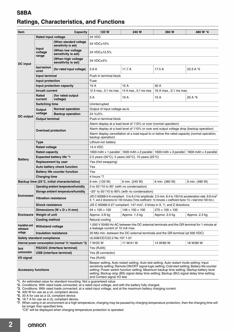
NomenclatureFront viewS8BA-24D24D120LF (120 W)
S8BA-24D24D240LF (240 W)
Enlarged view of the operation panel
S8BA-24D24D360LF (360 W)S8BA-24D24D480LF (480 W)
1
2
34
5
6
7
1
2
34
5
6
7
8
9
10
1
2
34
5
6
7
No. Name Function
1 Operation panel Describe the name of each part.
2 DC output terminal block Connect to load lines.
3 DC input terminal block Connect to input lines.
4 GR terminal Ground this terminal to less than 100 Ω to improve noise resistance and prevent electrical shock.
5 USB port Connect to a USB cable.
6 RS-232C port Connect to a RS-232C cable.
7 CONTACT port I/O port. Connect to a signal line.
8 “Status indicator” digital indicator The seven-segment display indicates the status of the UPS.
9 “Beep Stop/Test” switch Stop the beeper and perform self-diagnosis testing.
10 “Power” switch Turn the power of the UPS ON/OFF.
S8BA
4
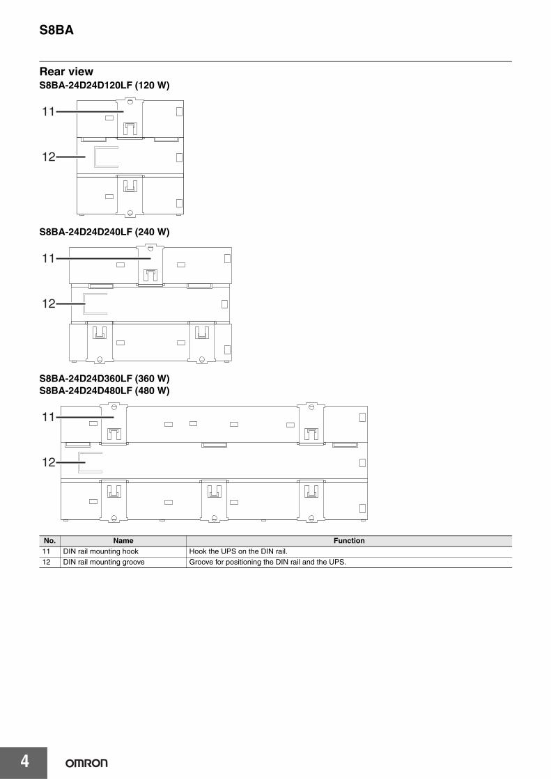
Rear viewS8BA-24D24D120LF (120 W)
S8BA-24D24D240LF (240 W)
S8BA-24D24D360LF (360 W)S8BA-24D24D480LF (480 W)
No. Name Function11 DIN rail mounting hook Hook the UPS on the DIN rail.12 DIN rail mounting groove Groove for positioning the DIN rail and the UPS.
11
12
11
12
11
12
S8BA
5
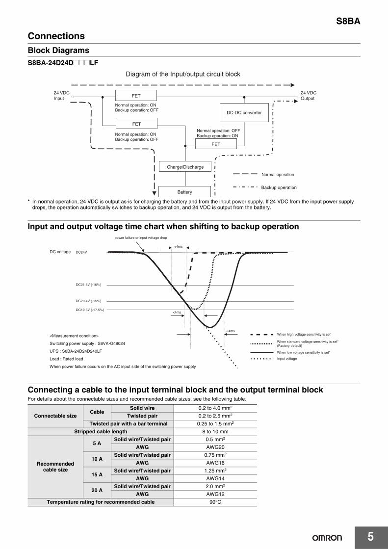
ConnectionsBlock DiagramsS8BA-24D24D@@@LF
* In normal operation, 24 VDC is output as-is for charging the battery and from the input power supply. If 24 VDC from the input power supply drops, the operation automatically switches to backup operation, and 24 VDC is output from the battery.
Input and output voltage time chart when shifting to backup operation
Connecting a cable to the input terminal block and the output terminal blockFor details about the connectable sizes and recommended cable sizes, see the following table.
Connectable sizeCable
Solid wire 0.2 to 4.0 mm2
Twisted pair 0.2 to 2.5 mm2
Twisted pair with a bar terminal 0.25 to 1.5 mm2
Stripped cable length 8 to 10 mm
Recommended cable size
5 ASolid wire/Twisted pair 0.5 mm2
AWG AWG20
10 ASolid wire/Twisted pair 0.75 mm2
AWG AWG16
15 ASolid wire/Twisted pair 1.25 mm2
AWG AWG14
20 ASolid wire/Twisted pair 2.0 mm2
AWG AWG12
Temperature rating for recommended cable 90°C
Diagram of the Input/output circuit block
FET
FET
Charge/Discharge
Battery
DC-DC converter
Normal operation
Backup operation
FET
24 VDCInput
24 VDCOutput
Normal operation: OFFBackup operation: ON
Normal operation: ONBackup operation: OFF
Normal operation: ONBackup operation: OFF
<4ms
<4msWhen high voltage sensitivity is set*
When standard voltage sensitivity is set*(Factory default)
When low voltage sensitivity is set*
Input voltage
<4ms
power failure or input voltage drop
DC21.6V (-10%)
DC20.4V (-15%)
DC19.8V (-17.5%)
<Measurement condition>
Switching power supply : S8VK-G48024
UPS : S8BA-24D24D240LF
Load : Rated load
When power failure occurs on the AC input side of the switching power supply
DC voltage DC24V
S8BA
6
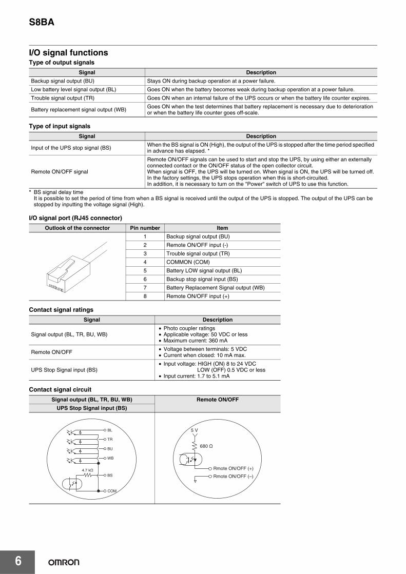
I/O signal functionsType of output signals
Type of input signals
* BS signal delay timeIt is possible to set the period of time from when a BS signal is received until the output of the UPS is stopped. The output of the UPS can be stopped by inputting the voltage signal (High).
I/O signal port (RJ45 connector)
Contact signal ratings
Contact signal circuit
Signal Description
Backup signal output (BU) Stays ON during backup operation at a power failure.
Low battery level signal output (BL) Goes ON when the battery becomes weak during backup operation at a power failure.
Trouble signal output (TR) Goes ON when an internal failure of the UPS occurs or when the battery life counter expires.
Battery replacement signal output (WB) Goes ON when the test determines that battery replacement is necessary due to deterioration or when the battery life counter goes off-scale.
Signal Description
Input of the UPS stop signal (BS) When the BS signal is ON (High), the output of the UPS is stopped after the time period specified in advance has elapsed. *
Remote ON/OFF signal
Remote ON/OFF signals can be used to start and stop the UPS, by using either an externally connected contact or the ON/OFF status of the open collector circuit.When signal is OFF, the UPS will be turned on. When signal is ON, the UPS will be turned off.In the factory settings, the UPS stops operation when this is short-circuited.In addition, it is necessary to turn on the "Power" switch of UPS to use this function.
Outlook of the connector Pin number Item
1 Backup signal output (BU)
2 Remote ON/OFF input (-)
3 Trouble signal output (TR)
4 COMMON (COM)
5 Battery LOW signal output (BL)
6 Backup stop signal input (BS)
7 Battery Replacement Signal output (WB)
8 Remote ON/OFF input (+)
Signal Description
Signal output (BL, TR, BU, WB)• Photo coupler ratings• Applicable voltage: 50 VDC or less• Maximum current: 360 mA
Remote ON/OFF • Voltage between terminals: 5 VDC• Current when closed: 10 mA max.
UPS Stop Signal input (BS)• Input voltage: HIGH (ON) 8 to 24 VDC
LOW (OFF) 0.5 VDC or less• Input current: 1.7 to 5.1 mA
Signal output (BL, TR, BU, WB) Remote ON/OFF
UPS Stop Signal input (BS)
BL
TR
BU
WB
BS
COM
4.7 kΩ
5 V
680 Ω
Rmote ON/OFF (+)
Rmote ON/OFF (–)
S8BA
7
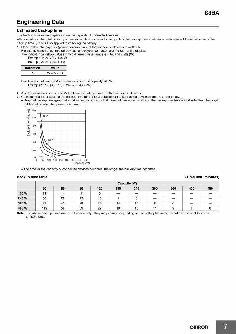
Engineering DataEstimated backup timeThe backup time varies depending on the capacity of connected devices.After calculating the total capacity of connected devices, refer to the graph of the backup time to obtain an estimation of the initial value of the backup time. (This is also applied to checking the battery.)1. Convert the total capacity (power consumption) of the connected devices to watts (W).
For the indication of connected devices, check your computer and the rear of the display.The indicator can show values in two different ways: amperes (A), and watts (W).
Example 1: 24 VDC, 145 WExample 2: 24 VDC, 1.8 A
For devices that use the A indication, convert the capacity into W.Example 2: 1.8 (A) = 1.8 × 24 (W) = 43.2 (W)
2. Add the values converted into W to obtain the total capacity of the connected devices.3. Calculate the initial value of the backup time for the total capacity of the connected devices from the graph below.
• Graph of backup time (graph of initial values for products that have not been used at 25°C). The backup time becomes shorter than the graph (table) below when temperature is lower.
• The smaller the capacity of connected devices becomes, the longer the backup time becomes.
Backup time table (Time unit: minutes)
Note: The above backup times are for reference only. They may change depending on the battery life and external environment (such as temperature).
Indication Value
A W = A × 24
Capacity (W)
30 60 90 120 180 240 300 360 420 480
120 W 29 14 9 6 — — — — — —
240 W 58 29 19 15 9 6 — — — —
360 W 87 43 28 22 14 10 8 6 — —
480 W 119 59 39 29 19 15 11 9 8 6
120 W
480 W
360 W
240 W
Capacity (W)
Bac
kup
time
(Min
utes
)
0 480
120
100
80
60
40
20
060 120 180 240 300 360 420
S8BA
8
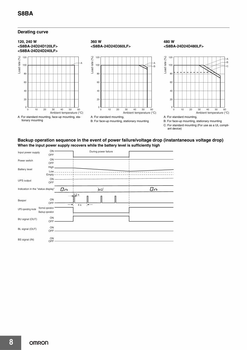
Derating curve
Backup operation sequence in the event of power failure/voltage drop (instantaneous voltage drop)When the input power supply recovers while the battery level is sufficiently high
Ambient temperature (°C)
Load
rat
e (%
)
A
0 10 20 30 40 50 60
120
100
80
60
40
20
0
A: For standard mounting, face-up mounting, sta-tionary mounting
AB
0 10 20 30 40 50 60
120
100
80
60
40
20
0
Ambient temperature (°C)
Load
rat
e (%
)
A: For standard mounting,B: For face-up mounting, stationary mounting
A
C
B
0 10 20 30 40 50 60
120
100
80
60
40
20
0
Ambient temperature (°C)
Load
rat
e (%
)
A: For standard mounting,B: For face-up mounting, stationary mountingC: For standard mounting (For use as a UL compli-
ant device)
120, 240 W<S8BA-24D24D120LF><S8BA-24D24D240LF>
360 W<S8BA-24D24D360LF>
480 W<S8BA-24D24D480LF>
0.2 s
4 s
Input power supply
Power switch
Battery level
UPS output
Indication in the "status display"
Beeper
UPS operating mode
BU signal (OUT)
BL signal (OUT)
BS signal (IN)
Normal operation
Backup operation
ON
ON
ON
OFF
OFF
OFF
OFF
OFF
OFF
During power failure
High
LowEmpty
OFF
ON
ON
ON
ON
S8BA
9
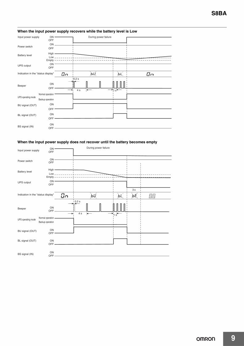
When the input power supply recovers while the battery level is Low
When the input power supply does not recover until the battery becomes empty
0.2 s
4 s 1 s
During power failure
Power switch
Battery level
UPS output
Indication in the "status display"
Beeper
UPS operating mode
BU signal (OUT)
BL signal (OUT)
BS signal (IN)
Normal operation
Backup operation
ON
ON
ON
OFF
OFF
OFF
OFF
OFF
OFF
HighLow
Empty
OFF
ON
ON
ON
ON
Input power supply
1 s
3 s
During power failureInput power supply
Power switch
Battery level
UPS output
Indication in the "status display"
Beeper
UPS operating mode
BU signal (OUT)
BL signal (OUT)
BS signal (IN)
Normal operation
Backup operation
ON
ON
ON
OFF
OFF
OFF
OFF
OFF
OFF
High
LowEmpty
OFF
ON
ON
ON
ON
0.2 s
4 s
S8BA
10
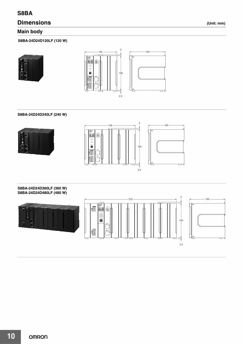
Dimensions (Unit: mm)
Main body
10094
100
2
2.5
S8BA-24D24D120LF (120 W)
S8BA-24D24D240LF (240 W)
100148
100
2
2.5
S8BA-24D24D360LF (360 W)S8BA-24D24D480LF (480 W)
270 100
2.5
100
2
S8BA
11
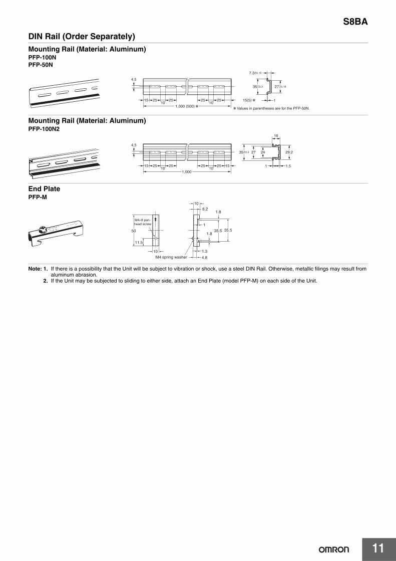
DIN Rail (Order Separately)Mounting Rail (Material: Aluminum)PFP-100N PFP-50N
Mounting Rail (Material: Aluminum)PFP-100N2
End PlatePFP-M
Note: 1. If there is a possibility that the Unit will be subject to vibration or shock, use a steel DIN Rail. Otherwise, metallic filings may result from aluminum abrasion.
2. If the Unit may be subjected to sliding to either side, attach an End Plate (model PFP-M) on each side of the Unit.
4.5
15 25 2510 10
1,000 (500) *25 25 15(5) *
35±0.3
7.3±0.15
27±0.15
1
* Values in parentheses are for the PFP-50N.
4.5
15 25 2510 10
1,000
25 25 15 1 1.5
29.2242735±0.3
16
1.3
4.8
35.5 35.51.8
1.8
106.2
1
50
11.5
10M4 spring washer
M4×8 pan-head screw
S8BA
12
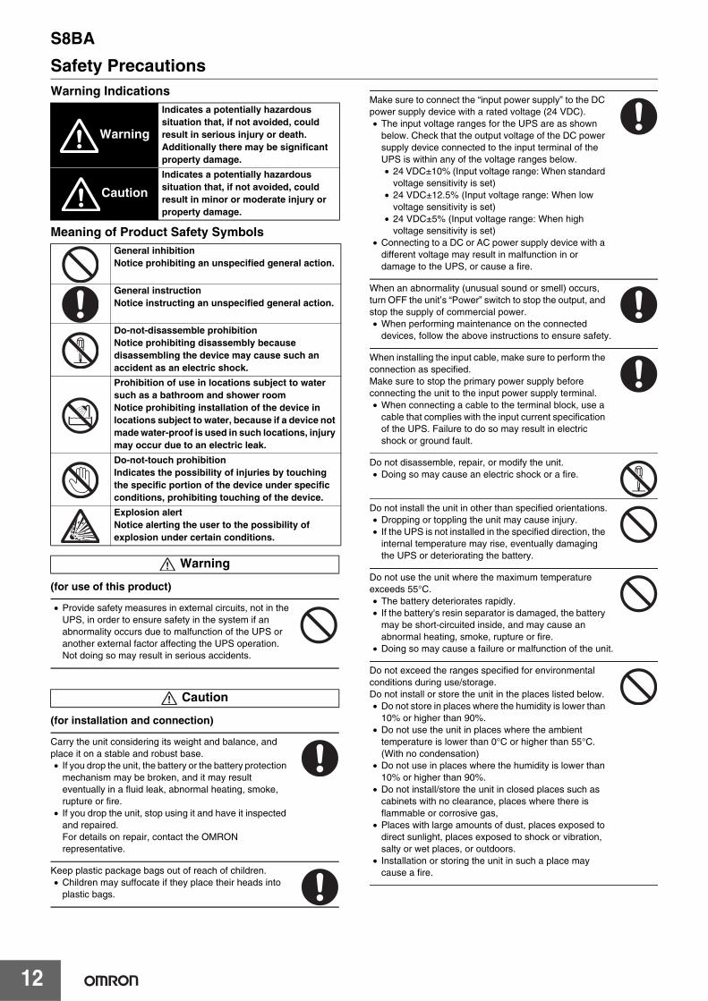
Safety PrecautionsWarning Indications
Meaning of Product Safety Symbols
(for use of this product)
• Provide safety measures in external circuits, not in the UPS, in order to ensure safety in the system if an abnormality occurs due to malfunction of the UPS or another external factor affecting the UPS operation. Not doing so may result in serious accidents.
(for installation and connection)
Carry the unit considering its weight and balance, and place it on a stable and robust base.• If you drop the unit, the battery or the battery protection
mechanism may be broken, and it may result eventually in a fluid leak, abnormal heating, smoke, rupture or fire.
• If you drop the unit, stop using it and have it inspected and repaired.For details on repair, contact the OMRON representative.
Keep plastic package bags out of reach of children.• Children may suffocate if they place their heads into
plastic bags.
Make sure to connect the “input power supply” to the DC power supply device with a rated voltage (24 VDC).• The input voltage ranges for the UPS are as shown
below. Check that the output voltage of the DC power supply device connected to the input terminal of the UPS is within any of the voltage ranges below.• 24 VDC±10% (Input voltage range: When standard
voltage sensitivity is set)• 24 VDC±12.5% (Input voltage range: When low
voltage sensitivity is set)• 24 VDC±5% (Input voltage range: When high
voltage sensitivity is set)• Connecting to a DC or AC power supply device with a
different voltage may result in malfunction in or damage to the UPS, or cause a fire.
When an abnormality (unusual sound or smell) occurs, turn OFF the unit’s “Power” switch to stop the output, and stop the supply of commercial power.• When performing maintenance on the connected
devices, follow the above instructions to ensure safety.
When installing the input cable, make sure to perform the connection as specified.Make sure to stop the primary power supply before connecting the unit to the input power supply terminal.• When connecting a cable to the terminal block, use a
cable that complies with the input current specification of the UPS. Failure to do so may result in electric shock or ground fault.
Do not disassemble, repair, or modify the unit.• Doing so may cause an electric shock or a fire.
Do not install the unit in other than specified orientations.• Dropping or toppling the unit may cause injury.• If the UPS is not installed in the specified direction, the
internal temperature may rise, eventually damaging the UPS or deteriorating the battery.
Do not use the unit where the maximum temperature exceeds 55°C.• The battery deteriorates rapidly.• If the battery's resin separator is damaged, the battery
may be short-circuited inside, and may cause an abnormal heating, smoke, rupture or fire.
• Doing so may cause a failure or malfunction of the unit.
Do not exceed the ranges specified for environmental conditions during use/storage.Do not install or store the unit in the places listed below.• Do not store in places where the humidity is lower than
10% or higher than 90%.• Do not use the unit in places where the ambient
temperature is lower than 0°C or higher than 55°C. (With no condensation)
• Do not use in places where the humidity is lower than 10% or higher than 90%.
• Do not install/store the unit in closed places such as cabinets with no clearance, places where there is flammable or corrosive gas,
• Places with large amounts of dust, places exposed to direct sunlight, places exposed to shock or vibration, salty or wet places, or outdoors.
• Installation or storing the unit in such a place may cause a fire.
Warning
Indicates a potentially hazardous situation that, if not avoided, could result in serious injury or death. Additionally there may be significant property damage.
Caution
Indicates a potentially hazardous situation that, if not avoided, could result in minor or moderate injury or property damage.
General inhibitionNotice prohibiting an unspecified general action.
General instructionNotice instructing an unspecified general action.
Do-not-disassemble prohibitionNotice prohibiting disassembly because disassembling the device may cause such an accident as an electric shock.
Prohibition of use in locations subject to water such as a bathroom and shower roomNotice prohibiting installation of the device in locations subject to water, because if a device not made water-proof is used in such locations, injury may occur due to an electric leak.
Do-not-touch prohibitionIndicates the possibility of injuries by touching the specific portion of the device under specific conditions, prohibiting touching of the device.
Explosion alertNotice alerting the user to the possibility of explosion under certain conditions.
Warning
Caution

S8BA
13
When you use plug strip and other plugs to connect additional devices, do not connect devices that exceed the current capacity of the available plugs.• The current protection of the unit may operate, which
may stop the output.• The cable heats up, which may cause a fire.
Do not pinch or sharply bend the cable.Do not fold or knot the cable.• Doing so may cause the cable to be damaged or
heated, which may cause an electric shock or a fire.• If the cable is damaged, stop using the unit and have
the cable repaired.• For details on repair, contact our sales personnel.
Connect only devices using 24 VDC rated voltage.• The rated output voltage of the UPS is 24 VDC.• Overvoltage or overcurrent may damage the
connected devices.
All the accessories contained in the product package can be used for the UPS only. Do not use any of them for other devices.• Be sure to observe this to use the UPS safely.
Include a breaker between the “input power supply” of the UPS and the DC power supply devices. And, install the breaker where it is easy to operate.
To use this product as a CE marking compliant device, use a 2-meter or shorter connection cable.
Do not block the air vents (upper and lower).• Doing so will cause the internal temperature to rise,
which may cause the unit to fail and the battery to deteriorate.
• For stationary installation, leave a space of 50 mm or more above the top, and for installation using a DIN rail and screw clamps, leave a space of 50 mm or more above the top and below the bottom each.
Do not connect the RS232C port or the CONTACT port to a LAN device using a LAN cable.• Connection to a LAN device may result in malfunction
in or damage to the UPS or the LAN device.
(for use)
Do not allow the unit to come in contact with water. If you drop the unit, stop using it.• Doing so may cause an electric shock or a fire.• Doing so may cause an abnormal heating, smoke,
rupture, or fire on the battery.• If the unit becomes wet or is dropped, immediately
stop using it, disconnect the input power supply from the wall outlet (commercial power source) and have it inspected and repaired.
• For details on repair, contact our sales personnel.
When the battery is dead, replace it immediately or stop using the unit.• Continuing the use of it may cause fire or electric
shock due to liquid leaks.
* The values in the table are the expected life under standard use conditions and are not guaranteed.
Occasionally, wipe off dust on the input terminal block and the output terminal block with a dry cloth.• Accumulated dust may cause a fire.• Before wiping off dust, stop all connected devices and
the unit, and stop the supply of commercial power.
Do not use the unit in a closed place and do not cover the unit.• Doing so may cause abnormal heating or a fire.
If you notice something unusual such as abnormal sound or smell, discoloration, deformation, and heating, turn OFF the unit’s “Power” switch to stop the output and stop the supply from the “input power supply”.• Using the unit under such conditions may cause an
abnormal heating, rupture or fire.• If this situation arises, be sure to stop using the UPS
and request our sales personnel for inspection and repair.
• A readily accessible disconnect device shall be incorporated external to the equipment.
If fluid leaks from the interior, do not touch the fluid.• Doing so may cause blindness or burns.• If the fluid contacts your eyes or skin, wash it out with
lots of clean water and consult your doctor. The fluid may damage your eye if your eye is left untreated.
Do not place any objects on the unit, and do not drop heavy objects onto the unit.• Doing so may cause distortion/damage to the case or
a failure of the internal circuit, which may cause a fire.
The unit is equipped with a bypass circuit which is able to supply electric power to connected devices even when the inner control circuit is broken down by defects or malfunctions.• If you want to stop the output, stop the source of the
“input power supply”.• Output is continuing even when all indicators of the
front panel are off.• Output ON/OFF cannot be controlled with the “Power”
switch on the front panel.
When charging the battery, if the battery cannot be charged completely even after the predetermined charging time, turn OFF the “Power” switch of the unit to stop charging the battery.• Otherwise, it may cause an abnormal heating, smoke,
rupture or fire on the battery.
(for maintenance)
When maintaining the connected equipment, turn OFF the unit’s “Power” switch to stop the output, and stop the supply of the “input power supply”.• Even if the input power supply to the UPS is stopped
while it is in operation, the power output of his unit does not stop and power is supplied from the battery.
Do not disassemble, repair, or modify the unit.• Doing so may cause an electric shock or a fire.
If fluid leaks from the interior, do not touch the fluid.• Doing so may cause blindness or burns.• If the fluid contacts your eyes or skin, wash it out with
lots of clean water and consult your doctor.
Ambient temperature Expected life
50°C 2.5 years
40°C 5 years
25°C 10 years

S8BA
14
Do not throw the unit into fire.• Since the battery is incorporated in the unit, the
insulator may melt, the gas exhaust valve or protection mechanism may be damaged, or the electrolyte may catch fire, and it may result eventually in an abnormal heating, smoke, rupture or fire.
Do not insert metal objects into the input terminal block and the output terminal block of the UPS.• Doing so may result in electric shock.
Do not insert metal objects into the battery connectors.Do not short between the connector terminals.• Doing so may result in electric shock.• The battery's protection board may be damaged due
to a short-circuit.
(for battery replacement)
Risk of explosion if battery is replaced by an incorrect type.• Not doing so may cause a fire.• Battery pack for; product model: S8BA-B120L.
Do not replace the battery in a place where there is flammable gas.• Spark may occur when connecting the battery, which
may cause an explosion or fire.
If fluid leaks from the battery, do not touch the fluid.• Doing so may cause blindness or burns.• If the fluid contacts your eyes or skin, wash it out with
lots of clean water and consult your doctor.
Do not disassemble or modify the battery.• A safety mechanism and protection mechanism to
prevent danger are embedded into the battery. If they are damaged, it may cause an abnormal heating, smoke, rupture or fire on the battery.
Do not drop the battery and do not expose it to strong impact.• Doing so may cause a leakage, abnormal heating,
smoke, rupture or fire on the battery. And, if the battery's protection mechanism is broken, the battery may be charged at an abnormal current or voltage, an abnormal chemical reaction may occur inside the battery, and it may result eventually in an abnormal heating, smoke, rupture or fire.
Do not short the battery with metal objects.• Doing so could cause an electric shock, fire or burn.• Some electrical energy still remains inside the spent
battery.
Do not dispose of battery in a fire or damage battery.• The insulator inside the battery may melt, the gas
exhaust valve or protection mechanism may be damaged, or the electrolyte may catch fire, and it may result eventually in abnormal heating, smoke, rupture or fire.
Do not use a new battery and an old battery at the same time.• The battery may be excessively discharged while
being used or excessively charged while being charged, an abnormal chemical reaction may occur inside the battery, and it may result eventually in an abnormal heating, smoke, rupture or fire.
• A battery can present a risk of electrical shock and high short circuit current.
• Contact with any part of a grounded battery can result in electrical shock.
• The following precautions should be observed when working on batteries:(a) Remove watches, rings, or other metal objects.(b) Use screwdrivers with insulated handles.(c) Wear rubber gloves and boots.(d) Do not lay tools or metal parts on top of batteries.(e) Remove the connection from ground if any part of
the battery is determined to be grounded.
Dispose of or collect (recycle) the battery according to your own rules set for that purpose or as instructed by laws and regulations. Do not dispose of it in fire. Otherwise, it could explode.
Before usingCharge the battery soon after purchasing the unit.• If not used for a long time after being purchased, the UPS may
become unusable because the characteristics of its battery become inferior.
• Connect the UPS to the input power supply and turn ON the “Power” switch to charge the battery.
If the UPS is moved from a warm place to a cold place, start using it after leaving it as-is for a few hours.• If the UPS is suddenly moved to a warm place, water may adhere
to it (condensation). In such a case, if power is supplied without checking the condition, the UPS may be damaged.
• Take measures against the unexpected events such as protecting data and making the system redundant.
• The UPS may stop its power due to failure.
For ConnectionBe careful not to let a short-circuit occur between output lines of the UPS and not to let an output line and the ground be short-circuited (a ground fault).• Otherwise, the UPS may be damaged.
To transfer or sell the UPS to a third party, attach all the documents and other accessories contained in the product package to the UPS. It is supposed that the UPS is to be used in accordance with the conditions specified in the attached documents.• The details related to safety are described in this document. Check
the details before using the UPS. In case you lose this document, download a copy from the Omron Website.
While Using the UPSTurn OFF the “Power” switch of the UPS before turning OFF the input power supply.• When the input power supply is stopped, backup operation starts.• If the frequency of backup operation becomes high, the battery life
may be significantly reduced.Do not use the UPS for purposes requiring frequent backup operation.• The battery will deteriorate and become unable to last for the
specified backup time.
For StorageTo store the UPS for a long time, store it in an environment where the ambient temperature is 25°C or lower, and charge the battery once every year for 10 to 15 minutes.• The battery discharges itself even if it is not used. If the battery is
left unused for a long time, it goes into a state of over-discharge. In such a case, the backup time may become shorter, or the battery cannot be used anymore.
• We recommend an environment where the ambient temperature is 25°C or lower to store the UPS for a long time.
• Keep the “Power” switch of the UPS turned OFF during storage.• Do not install or store the UPS in a location exposed to direct
sunlight.• The built-in battery may deteriorate rapidly due to an increase in
temperature and become unusable.
Precautions for Safe Use
S8BA
15
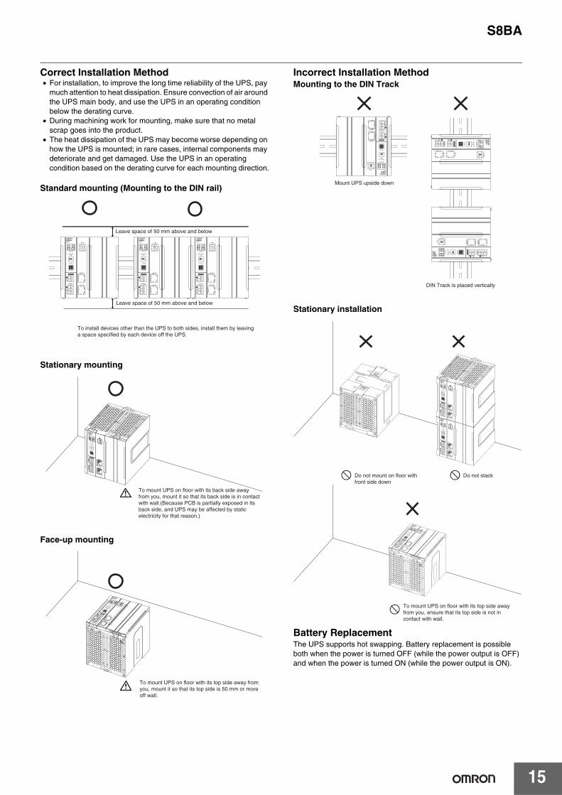
Correct Installation Method• For installation, to improve the long time reliability of the UPS, pay
much attention to heat dissipation. Ensure convection of air around the UPS main body, and use the UPS in an operating condition below the derating curve.
• During machining work for mounting, make sure that no metal scrap goes into the product.
• The heat dissipation of the UPS may become worse depending on how the UPS is mounted; in rare cases, internal components may deteriorate and get damaged. Use the UPS in an operating condition based on the derating curve for each mounting direction.
Standard mounting (Mounting to the DIN rail)
Stationary mounting
Face-up mounting
Incorrect Installation MethodMounting to the DIN Track
Stationary installation
Battery ReplacementThe UPS supports hot swapping. Battery replacement is possible both when the power is turned OFF (while the power output is OFF) and when the power is turned ON (while the power output is ON).
To install devices other than the UPS to both sides, install them by leaving a space specified by each device off the UPS.
Leave space of 50 mm above and below
Leave space of 50 mm above and below
To mount UPS on floor with its back side away from you, mount it so that its back side is in contact with wall.(Because PCB is partially exposed in its back side, and UPS may be affected by static electricity for that reason.)
To mount UPS on floor with its top side away from you, mount it so that its top side is 50 mm or more off wall.
Mount UPS upside down
DIN Track is placed vertically
Do not stackDo not mount on floor with front side down
To mount UPS on floor with its top side away from you, ensure that its top side is not in contact with wall.
S8BA
16
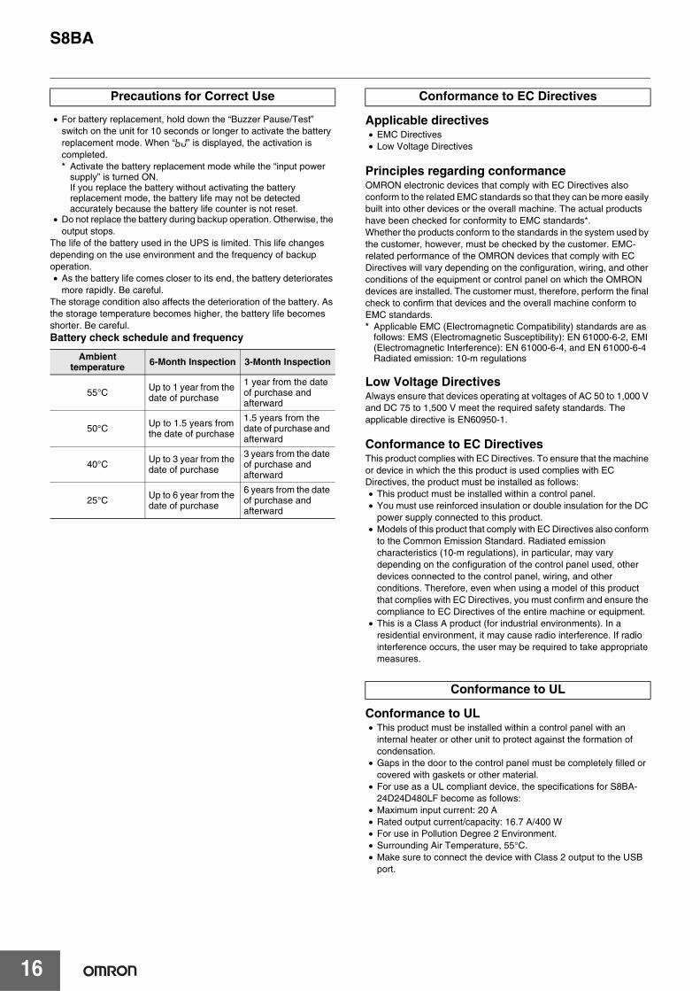
• For battery replacement, hold down the “Buzzer Pause/Test” switch on the unit for 10 seconds or longer to activate the battery replacement mode. When “ ” is displayed, the activation is completed.* Activate the battery replacement mode while the “input power
supply” is turned ON.If you replace the battery without activating the battery replacement mode, the battery life may not be detected accurately because the battery life counter is not reset.
• Do not replace the battery during backup operation. Otherwise, the output stops.
The life of the battery used in the UPS is limited. This life changes depending on the use environment and the frequency of backup operation.• As the battery life comes closer to its end, the battery deteriorates
more rapidly. Be careful.The storage condition also affects the deterioration of the battery. As the storage temperature becomes higher, the battery life becomes shorter. Be careful.Battery check schedule and frequency
Applicable directives• EMC Directives• Low Voltage Directives
Principles regarding conformanceOMRON electronic devices that comply with EC Directives also conform to the related EMC standards so that they can be more easily built into other devices or the overall machine. The actual products have been checked for conformity to EMC standards*.Whether the products conform to the standards in the system used by the customer, however, must be checked by the customer. EMC-related performance of the OMRON devices that comply with EC Directives will vary depending on the configuration, wiring, and other conditions of the equipment or control panel on which the OMRON devices are installed. The customer must, therefore, perform the final check to confirm that devices and the overall machine conform to EMC standards.* Applicable EMC (Electromagnetic Compatibility) standards are as
follows: EMS (Electromagnetic Susceptibility): EN 61000-6-2, EMI (Electromagnetic Interference): EN 61000-6-4, and EN 61000-6-4 Radiated emission: 10-m regulations
Low Voltage DirectivesAlways ensure that devices operating at voltages of AC 50 to 1,000 V and DC 75 to 1,500 V meet the required safety standards. The applicable directive is EN60950-1.
Conformance to EC DirectivesThis product complies with EC Directives. To ensure that the machine or device in which the this product is used complies with EC Directives, the product must be installed as follows:• This product must be installed within a control panel.• You must use reinforced insulation or double insulation for the DC
power supply connected to this product.• Models of this product that comply with EC Directives also conform
to the Common Emission Standard. Radiated emission characteristics (10-m regulations), in particular, may vary depending on the configuration of the control panel used, other devices connected to the control panel, wiring, and other conditions. Therefore, even when using a model of this product that complies with EC Directives, you must confirm and ensure the compliance to EC Directives of the entire machine or equipment.
• This is a Class A product (for industrial environments). In a residential environment, it may cause radio interference. If radio interference occurs, the user may be required to take appropriate measures.
Conformance to UL• This product must be installed within a control panel with an
internal heater or other unit to protect against the formation of condensation.
• Gaps in the door to the control panel must be completely filled or covered with gaskets or other material.
• For use as a UL compliant device, the specifications for S8BA-24D24D480LF become as follows:
• Maximum input current: 20 A• Rated output current/capacity: 16.7 A/400 W• For use in Pollution Degree 2 Environment.• Surrounding Air Temperature, 55°C.• Make sure to connect the device with Class 2 output to the USB
port.
Precautions for Correct Use
Ambient temperature 6-Month Inspection 3-Month Inspection
55°C Up to 1 year from the date of purchase
1 year from the date of purchase and afterward
50°C Up to 1.5 years from the date of purchase
1.5 years from the date of purchase and afterward
40°C Up to 3 year from the date of purchase
3 years from the date of purchase and afterward
25°C Up to 6 year from the date of purchase
6 years from the date of purchase and afterward
Conformance to EC Directives
Conformance to UL

17
MEMO

MEMO
18
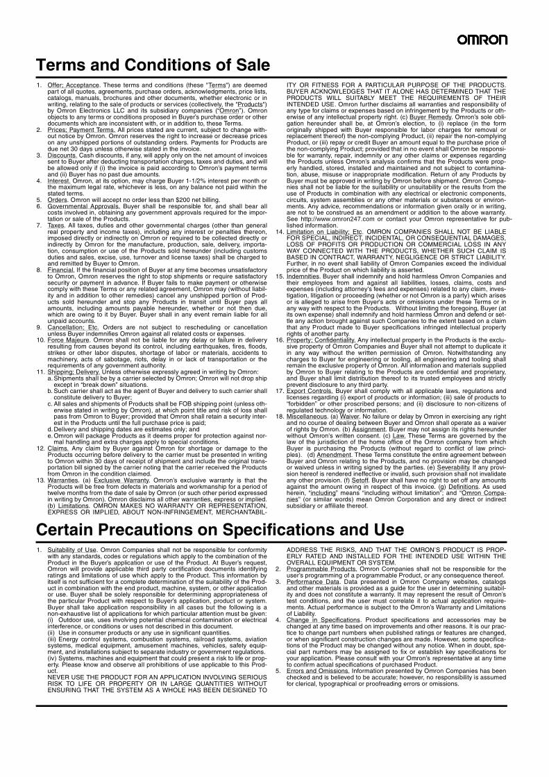
Terms and Conditions of Sale1. Offer; Acceptance. These terms and conditions (these "Terms") are deemed
part of all quotes, agreements, purchase orders, acknowledgments, price lists,catalogs, manuals, brochures and other documents, whether electronic or inwriting, relating to the sale of products or services (collectively, the "Products")by Omron Electronics LLC and its subsidiary companies (“Omron”). Omronobjects to any terms or conditions proposed in Buyer’s purchase order or otherdocuments which are inconsistent with, or in addition to, these Terms.
2. Prices; Payment Terms. All prices stated are current, subject to change with-out notice by Omron. Omron reserves the right to increase or decrease priceson any unshipped portions of outstanding orders. Payments for Products aredue net 30 days unless otherwise stated in the invoice.
3. Discounts. Cash discounts, if any, will apply only on the net amount of invoicessent to Buyer after deducting transportation charges, taxes and duties, and willbe allowed only if (i) the invoice is paid according to Omron’s payment termsand (ii) Buyer has no past due amounts.
4. Interest. Omron, at its option, may charge Buyer 1-1/2% interest per month orthe maximum legal rate, whichever is less, on any balance not paid within thestated terms.
5. Orders. Omron will accept no order less than $200 net billing.6. Governmental Approvals. Buyer shall be responsible for, and shall bear all
costs involved in, obtaining any government approvals required for the impor-tation or sale of the Products.
7. Taxes. All taxes, duties and other governmental charges (other than generalreal property and income taxes), including any interest or penalties thereon,imposed directly or indirectly on Omron or required to be collected directly orindirectly by Omron for the manufacture, production, sale, delivery, importa-tion, consumption or use of the Products sold hereunder (including customsduties and sales, excise, use, turnover and license taxes) shall be charged toand remitted by Buyer to Omron.
8. Financial. If the financial position of Buyer at any time becomes unsatisfactoryto Omron, Omron reserves the right to stop shipments or require satisfactorysecurity or payment in advance. If Buyer fails to make payment or otherwisecomply with these Terms or any related agreement, Omron may (without liabil-ity and in addition to other remedies) cancel any unshipped portion of Prod-ucts sold hereunder and stop any Products in transit until Buyer pays allamounts, including amounts payable hereunder, whether or not then due,which are owing to it by Buyer. Buyer shall in any event remain liable for allunpaid accounts.
9. Cancellation; Etc. Orders are not subject to rescheduling or cancellationunless Buyer indemnifies Omron against all related costs or expenses.
10. Force Majeure. Omron shall not be liable for any delay or failure in deliveryresulting from causes beyond its control, including earthquakes, fires, floods,strikes or other labor disputes, shortage of labor or materials, accidents tomachinery, acts of sabotage, riots, delay in or lack of transportation or therequirements of any government authority.
11. Shipping; Delivery. Unless otherwise expressly agreed in writing by Omron:a. Shipments shall be by a carrier selected by Omron; Omron will not drop ship
except in “break down” situations.b. Such carrier shall act as the agent of Buyer and delivery to such carrier shall
constitute delivery to Buyer;c. All sales and shipments of Products shall be FOB shipping point (unless oth-
erwise stated in writing by Omron), at which point title and risk of loss shallpass from Omron to Buyer; provided that Omron shall retain a security inter-est in the Products until the full purchase price is paid;
d. Delivery and shipping dates are estimates only; ande. Omron will package Products as it deems proper for protection against nor-
mal handling and extra charges apply to special conditions.12. Claims. Any claim by Buyer against Omron for shortage or damage to the
Products occurring before delivery to the carrier must be presented in writingto Omron within 30 days of receipt of shipment and include the original trans-portation bill signed by the carrier noting that the carrier received the Productsfrom Omron in the condition claimed.
13. Warranties. (a) Exclusive Warranty. Omron’s exclusive warranty is that theProducts will be free from defects in materials and workmanship for a period oftwelve months from the date of sale by Omron (or such other period expressedin writing by Omron). Omron disclaims all other warranties, express or implied.(b) Limitations. OMRON MAKES NO WARRANTY OR REPRESENTATION,EXPRESS OR IMPLIED, ABOUT NON-INFRINGEMENT, MERCHANTABIL-
ITY OR FITNESS FOR A PARTICULAR PURPOSE OF THE PRODUCTS.BUYER ACKNOWLEDGES THAT IT ALONE HAS DETERMINED THAT THEPRODUCTS WILL SUITABLY MEET THE REQUIREMENTS OF THEIRINTENDED USE. Omron further disclaims all warranties and responsibility ofany type for claims or expenses based on infringement by the Products or oth-erwise of any intellectual property right. (c) Buyer Remedy. Omron’s sole obli-gation hereunder shall be, at Omron’s election, to (i) replace (in the formoriginally shipped with Buyer responsible for labor charges for removal orreplacement thereof) the non-complying Product, (ii) repair the non-complyingProduct, or (iii) repay or credit Buyer an amount equal to the purchase price ofthe non-complying Product; provided that in no event shall Omron be responsi-ble for warranty, repair, indemnity or any other claims or expenses regardingthe Products unless Omron’s analysis confirms that the Products were prop-erly handled, stored, installed and maintained and not subject to contamina-tion, abuse, misuse or inappropriate modification. Return of any Products byBuyer must be approved in writing by Omron before shipment. Omron Compa-nies shall not be liable for the suitability or unsuitability or the results from theuse of Products in combination with any electrical or electronic components,circuits, system assemblies or any other materials or substances or environ-ments. Any advice, recommendations or information given orally or in writing,are not to be construed as an amendment or addition to the above warranty.See http://www.omron247.com or contact your Omron representative for pub-lished information.
14. Limitation on Liability; Etc. OMRON COMPANIES SHALL NOT BE LIABLEFOR SPECIAL, INDIRECT, INCIDENTAL, OR CONSEQUENTIAL DAMAGES,LOSS OF PROFITS OR PRODUCTION OR COMMERCIAL LOSS IN ANYWAY CONNECTED WITH THE PRODUCTS, WHETHER SUCH CLAIM ISBASED IN CONTRACT, WARRANTY, NEGLIGENCE OR STRICT LIABILITY.Further, in no event shall liability of Omron Companies exceed the individualprice of the Product on which liability is asserted.
15. Indemnities. Buyer shall indemnify and hold harmless Omron Companies andtheir employees from and against all liabilities, losses, claims, costs andexpenses (including attorney's fees and expenses) related to any claim, inves-tigation, litigation or proceeding (whether or not Omron is a party) which arisesor is alleged to arise from Buyer's acts or omissions under these Terms or inany way with respect to the Products. Without limiting the foregoing, Buyer (atits own expense) shall indemnify and hold harmless Omron and defend or set-tle any action brought against such Companies to the extent based on a claimthat any Product made to Buyer specifications infringed intellectual propertyrights of another party.
16. Property; Confidentiality. Any intellectual property in the Products is the exclu-sive property of Omron Companies and Buyer shall not attempt to duplicate itin any way without the written permission of Omron. Notwithstanding anycharges to Buyer for engineering or tooling, all engineering and tooling shallremain the exclusive property of Omron. All information and materials suppliedby Omron to Buyer relating to the Products are confidential and proprietary,and Buyer shall limit distribution thereof to its trusted employees and strictlyprevent disclosure to any third party.
17. Export Controls. Buyer shall comply with all applicable laws, regulations andlicenses regarding (i) export of products or information; (iii) sale of products to“forbidden” or other proscribed persons; and (ii) disclosure to non-citizens ofregulated technology or information.
18. Miscellaneous. (a) Waiver. No failure or delay by Omron in exercising any rightand no course of dealing between Buyer and Omron shall operate as a waiverof rights by Omron. (b) Assignment. Buyer may not assign its rights hereunderwithout Omron's written consent. (c) Law. These Terms are governed by thelaw of the jurisdiction of the home office of the Omron company from whichBuyer is purchasing the Products (without regard to conflict of law princi-ples). (d) Amendment. These Terms constitute the entire agreement betweenBuyer and Omron relating to the Products, and no provision may be changedor waived unless in writing signed by the parties. (e) Severability. If any provi-sion hereof is rendered ineffective or invalid, such provision shall not invalidateany other provision. (f) Setoff. Buyer shall have no right to set off any amountsagainst the amount owing in respect of this invoice. (g) Definitions. As usedherein, “including” means “including without limitation”; and “Omron Compa-nies” (or similar words) mean Omron Corporation and any direct or indirectsubsidiary or affiliate thereof.
Certain Precautions on Specifications and Use1. Suitability of Use. Omron Companies shall not be responsible for conformity
with any standards, codes or regulations which apply to the combination of theProduct in the Buyer’s application or use of the Product. At Buyer’s request,Omron will provide applicable third party certification documents identifyingratings and limitations of use which apply to the Product. This information byitself is not sufficient for a complete determination of the suitability of the Prod-uct in combination with the end product, machine, system, or other applicationor use. Buyer shall be solely responsible for determining appropriateness ofthe particular Product with respect to Buyer’s application, product or system.Buyer shall take application responsibility in all cases but the following is anon-exhaustive list of applications for which particular attention must be given:(i) Outdoor use, uses involving potential chemical contamination or electricalinterference, or conditions or uses not described in this document.(ii) Use in consumer products or any use in significant quantities.(iii) Energy control systems, combustion systems, railroad systems, aviationsystems, medical equipment, amusement machines, vehicles, safety equip-ment, and installations subject to separate industry or government regulations. (iv) Systems, machines and equipment that could present a risk to life or prop-erty. Please know and observe all prohibitions of use applicable to this Prod-uct. NEVER USE THE PRODUCT FOR AN APPLICATION INVOLVING SERIOUSRISK TO LIFE OR PROPERTY OR IN LARGE QUANTITIES WITHOUTENSURING THAT THE SYSTEM AS A WHOLE HAS BEEN DESIGNED TO
ADDRESS THE RISKS, AND THAT THE OMRON’S PRODUCT IS PROP-ERLY RATED AND INSTALLED FOR THE INTENDED USE WITHIN THEOVERALL EQUIPMENT OR SYSTEM.
2. Programmable Products. Omron Companies shall not be responsible for theuser’s programming of a programmable Product, or any consequence thereof.
3. Performance Data. Data presented in Omron Company websites, catalogsand other materials is provided as a guide for the user in determining suitabil-ity and does not constitute a warranty. It may represent the result of Omron’stest conditions, and the user must correlate it to actual application require-ments. Actual performance is subject to the Omron’s Warranty and Limitationsof Liability.
4. Change in Specifications. Product specifications and accessories may bechanged at any time based on improvements and other reasons. It is our prac-tice to change part numbers when published ratings or features are changed,or when significant construction changes are made. However, some specifica-tions of the Product may be changed without any notice. When in doubt, spe-cial part numbers may be assigned to fix or establish key specifications foryour application. Please consult with your Omron’s representative at any timeto confirm actual specifications of purchased Product.
5. Errors and Omissions. Information presented by Omron Companies has beenchecked and is believed to be accurate; however, no responsibility is assumedfor clerical, typographical or proofreading errors or omissions.
OMRON CANADA, INC. • HEAD OFFICEToronto, ON, Canada • 416.286.6465 • 866.986.6766 • www.omron247.com
OMRON ELECTRONICS DE MEXICO • HEAD OFFICEMéxico DF • 52.55.59.01.43.00 • 01-800-226-6766 • [email protected]
OMRON ELECTRONICS DE MEXICO • SALES OFFICEApodaca, N.L. • 52.81.11.56.99.20 • 01-800-226-6766 • [email protected]
OMRON ELETRÔNICA DO BRASIL LTDA • HEAD OFFICESão Paulo, SP, Brasil • 55.11.2101.6300 • www.omron.com.br
OMRON ARGENTINA • SALES OFFICECono Sur • 54.11.4783.5300
OMRON CHILE • SALES OFFICESantiago • 56.9.9917.3920
OTHER OMRON LATIN AMERICA SALES54.11.4783.5300
Authorized Distributor:
U22I-E-01 11/15 Note: Specifications are subject to change. © 2015 Omron Electronics LLC Printed in U.S.A.
Printed on recycled paper.
Automation Control Systems• Machine Automation Controllers (MAC) • Programmable Controllers (PLC) • Operator interfaces (HMI) • Distributed I/O • Software
Drives & Motion Controls • Servo & AC Drives • Motion Controllers & Encoders
Temperature & Process Controllers • Single and Multi-loop Controllers
Sensors & Vision• Proximity Sensors • Photoelectric Sensors • Fiber-Optic Sensors• Amplified Photomicrosensors • Measurement Sensors• Ultrasonic Sensors • Vision Sensors
Industrial Components • RFID/Code Readers • Relays • Pushbuttons & Indicators• Limit and Basic Switches • Timers • Counters • Metering Devices • Power Supplies
Safety • Laser Scanners • Safety Mats • Edges and Bumpers • Programmable Safety
Controllers • Light Curtains • Safety Relays • Safety Interlock Switches
OMRON AUTOMATION AND SAFETY • THE AMERICAS HEADQUARTERS • Chicago, IL USA • 847.843.7900 • 800.556.6766 • www.omron247.com
OMRON EUROPE B.V. • Wegalaan 67-69, NL-2132 JD, Hoofddorp, The Netherlands. • +31 (0) 23 568 13 00 • www.industrial.omron.eu
Mouser Electronics
Authorized Distributor
Click to View Pricing, Inventory, Delivery & Lifecycle Information: Omron:
S8BA-B120L S8BA-24D24D120LF S8BA-24D24D240LF S8BA-24D24D360LF S8BA-24D24D480LF