Embed Size (px)
Citation preview
SIMATIC S7 300 Automation Systems CPU 317T-2 DP: Controlling a physical axis ________________________________________________________
Introduction 1
Preparation 2
Learning units 3
Further information 4
SIMATIC
S7-300 Automation SystemsCPU 317T-2 DP: Controlling a physical axis
Getting Started
03/2008 A5E00251786-05
Safety Guidelines Safety Guidelines This manual contains notices you have to observe in order to ensure your personal safety, as well as to prevent damage to property. The notices referring to your personal safety are highlighted in the manual by a safety alert symbol, notices referring only to property damage have no safety alert symbol. These notices shown below are graded according to the degree of danger.
DANGER indicates that death or severe personal injury will result if proper precautions are not taken.
WARNING indicates that death or severe personal injury may result if proper precautions are not taken.
CAUTION with a safety alert symbol, indicates that minor personal injury can result if proper precautions are not taken.
CAUTION without a safety alert symbol, indicates that property damage can result if proper precautions are not taken.
NOTICE indicates that an unintended result or situation can occur if the corresponding information is not taken into account.
If more than one degree of danger is present, the warning notice representing the highest degree of danger will be used. A notice warning of injury to persons with a safety alert symbol may also include a warning relating to property damage.
Qualified Personnel The device/system may only be set up and used in conjunction with this documentation. Commissioning and operation of a device/system may only be performed by qualified personnel. Within the context of the safety notes in this documentation qualified persons are defined as persons who are authorized to commission, ground and label devices, systems and circuits in accordance with established safety practices and standards.
Prescribed Usage Note the following:
WARNING This device may only be used for the applications described in the catalog or the technical description and only in connection with devices or components from other manufacturers which have been approved or recommended by Siemens. Correct, reliable operation of the product requires proper transport, storage, positioning and assembly as well as careful operation and maintenance.
Trademarks All names identified by ® are registered trademarks of the Siemens AG. The remaining trademarks in this publication may be trademarks whose use by third parties for their own purposes could violate the rights of the owner.
Disclaimer of Liability We have reviewed the contents of this publication to ensure consistency with the hardware and software described. Since variance cannot be precluded entirely, we cannot guarantee full consistency. However, the information in this publication is reviewed regularly and any necessary corrections are included in subsequent editions.
Siemens AG Automation and Drives Postfach 48 48 90327 NÜRNBERG GERMANY
A5E00251786-05 Ⓟ 03/2008
Copyright © Siemens AG 2008. Technical data subject to change
CPU 317T-2 DP: Controlling a physical axis Getting Started, 03/2008, A5E00251786-05 3
Table of contents 1 Introduction................................................................................................................................................ 5 2 Preparation ................................................................................................................................................ 7
2.1 Requirements.................................................................................................................................7 2.2 Task ...............................................................................................................................................8
3 Learning units .......................................................................................................................................... 11 3.1 1. Step: Wiring..............................................................................................................................11 3.2 Optionally: Setting up the T station with the help of the wizard ...................................................12 3.3 2. Step: Configuring the CPU 317T-2 DP in HW -Config ............................................................14 3.4 3. Step: Changing the transmission rate at the MPI/DP interface ...............................................16 3.5 4. Step: Vital settings in your DP (DRIVE) configuration .............................................................16 3.6 5. Step: Generating technology system data...............................................................................17 3.7 6. Step: Configuring the drive with HW Config ............................................................................18 3.8 7. Step: Configuring the axis(axes) with S7T Config ...................................................................20 3.9 8. Step: Creating the technology DBs..........................................................................................25 3.10 9. Step: Configuring the drive with SimoComU ...........................................................................26 3.11 10. Step: Controlling the axis with the STEP 7 user program .....................................................29 3.12 11. Step: Trial run ........................................................................................................................30
4 Further information .................................................................................................................................. 31

Table of contents
CPU 317T-2 DP: Controlling a physical axis 4 Getting Started, 03/2008, A5E00251786-05
CPU 317T-2 DP: Controlling a physical axis Getting Started, 03/2008, A5E00251786-05 5
Introduction 1Introduction
This Getting Started contains a practical example guiding you through eleven steps in commissioning a fully functional application, and showing you how to carry out motion commands. It is thus a valuable help in getting started with the basic functions of a CPU 317T-2 DP. Depending on your degree of experience, working through the sample will take between one and two hours.
Note This Getting Started presumes that you have connected a SIMODRIVE 611 universal drive to the DP(DRIVE) interface of the CPU 317T-2 DP In case you do not have a drive, we recommend you refer to the Getting started documentation "CPU 317T-2 DP: Controlling a virtual axis
Note
You can also use the CPU 315T-2 DP instead of the CPU 317T-2 DP. To do this, select CPU 315T-2 DP in HW Config. Otherwise, the configuring steps are the same.

Introduction
CPU 317T-2 DP: Controlling a physical axis 6 Getting Started, 03/2008, A5E00251786-05
CPU 317T-2 DP: Controlling a physical axis Getting Started, 03/2008, A5E00251786-05 7
Preparation 22.1 Requirements
Requirements The following requirements must be fulfilled: ● An S7-300 station, consisting of:
– Power supply (PS), e.g. 6ES7 307-1KA00-0AA0 – CPU 317T-2DP with inserted MMC (4 MB or more). – Optional digital input module (DI) with bus connector, for example,
6ES7 321-1BH02-0AA0 – Optional digital output module (DO) with bus connector, for example,
6ES7 322-1BH01-0AA0 – Two optional front connectors for the digital modules
● A PG/PC with MPI interface and properly installed software packages and commissioning tools as listed below: – STEP 7 as of V5.4 SP2 – S7 Technology as of V4.1 – SimoCom U (Version 10.03.03 or higher)
● The PG/PC is connected to the CPU via the MPI/DP interface (transmission rate up to 12 Mbps; default 187.5 kbps): – PROFIBUS cable 6ES7901-4BD00-0XA0 (for transmission rates up to 12 Mbps)
● A SIMODRIVE 611U is interconnected with the CPU 317T-2 DP via DP(DRIVE) interface. ● The SIMODRIVE 611U modules:
– Controller module, for example, 6SN1 118-0NH00-0AAx – Optional Motion Control module with PROFIBUS DP, 6SN1 114-0NB01-0AA0 – Also required for operating the SIMODRIVE 611U: – A power unit, for example, 6SN1 12x-1Ax0x-0HAx – A motor, for example, 1FT6 031-xAK7x-xExx (rated speed 6000 rpm), for example,
with one absolute value encoder
Preparation 2.2 Task
CPU 317T-2 DP: Controlling a physical axis 8 Getting Started, 03/2008, A5E00251786-05
Note For the example of a drive in Getting Started we use a SIMODRIVE 611 universal training case. This training case is available under the following order number: • 6ZB2420-0AB00 or • 6SN1182-0EA00-3DP0 or • 6AU1700-8AA00-0AA0
● The configuration is completely installed and wired. For information, refer to Getting Started CPU 31x: Commissioning.
● You provided hardware limit switches and EMERGENCY-OFF switches for safe and reliable operation of the system.
WARNING
Operation of an S7-300 as part of plants or systems is subject to special rules and regulations, based on its field of application. Please note the current safety regulations for the prevention of accidents, e.g. IEC 204 (EMERGENCY-OFF equipment). You risk severe injury, or damage to machines and equipment if you ignore these directives.
2.2 Task
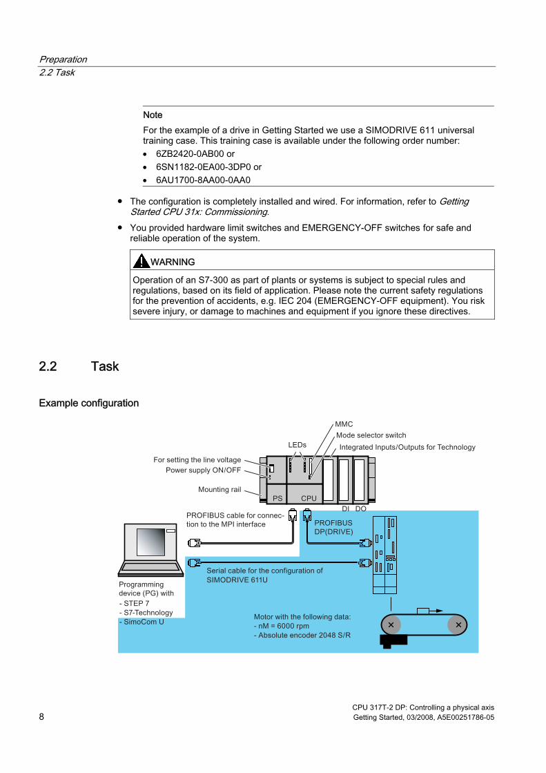
Example configuration
Preparation 2.2 Task
CPU 317T-2 DP: Controlling a physical axis Getting Started, 03/2008, A5E00251786-05 9
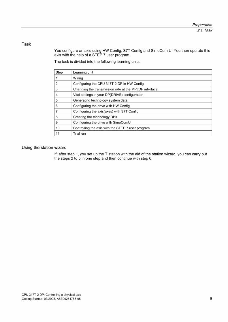
Task You configure an axis using HW Config, S7T Config and SimoCom U. You then operate this axis with the help of a STEP 7 user program. The task is divided into the following learning units:
Step Learning unit 1 Wiring 2 Configuring the CPU 317T-2 DP in HW Config 3 Changing the transmission rate at the MPI/DP interface 4 Vital settings in your DP(DRIVE) configuration 5 Generating technology system data 6 Configuring the drive with HW Config 7 Configuring the axis(axes) with S7T Config 8 Creating the technology DBs 9 Configuring the drive with SimoComU 10 Controlling the axis with the STEP 7 user program 11 Trial run
Using the station wizard If, after step 1, you set up the T station with the aid of the station wizard, you can carry out the steps 2 to 5 in one step and then continue with step 6.

Preparation 2.2 Task
CPU 317T-2 DP: Controlling a physical axis 10 Getting Started, 03/2008, A5E00251786-05
CPU 317T-2 DP: Controlling a physical axis Getting Started, 03/2008, A5E00251786-05 11
Learning units 33.1 1. Step: Wiring
WARNING You may come into contact with live wires. Always switch off power before you start wiring the S7-300.
Procedure A description of the installation and wiring of your 317T-2DP CPU is found in the Getting Started Collection S7-300 PLC: CPU 31x: Commissioning.
Learning units 3.2 Optionally: Setting up the T station with the help of the wizard
CPU 317T-2 DP: Controlling a physical axis 12 Getting Started, 03/2008, A5E00251786-05
3.2 Optionally: Setting up the T station with the help of the wizard The station wizard helps you to carry out several steps when configuring a CPU 31xT in one work cycle. You have the following options: ● Using the station wizards
Carry out the following described steps and then continue with learning unit "6th step". ● Not using the station wizards
Do not carry out the following described steps, instead, continue with the learning unit "2nd step".
Procedure Step Activity 1 Set up a new project in the SIMATIC Manager (e.g. "Getting Started CPU 317T"). 2 Select the Insert > Station > SIMATIC T Station menu command.
The "Set up T station" dialog box opens. Select the following settings in the fields: "CPU type": CPU317T-2 DP "Generate Technology System Data" option activated "MPI/DP": New, type MPI, transmission rate 1.5 Mbps "PG/PC": Not used Carry out the settings in all other fields. If required, press the button "Help" to obtain additional information.
Learning units 3.2 Optionally: Setting up the T station with the help of the wizard
CPU 317T-2 DP: Controlling a physical axis Getting Started, 03/2008, A5E00251786-05 13
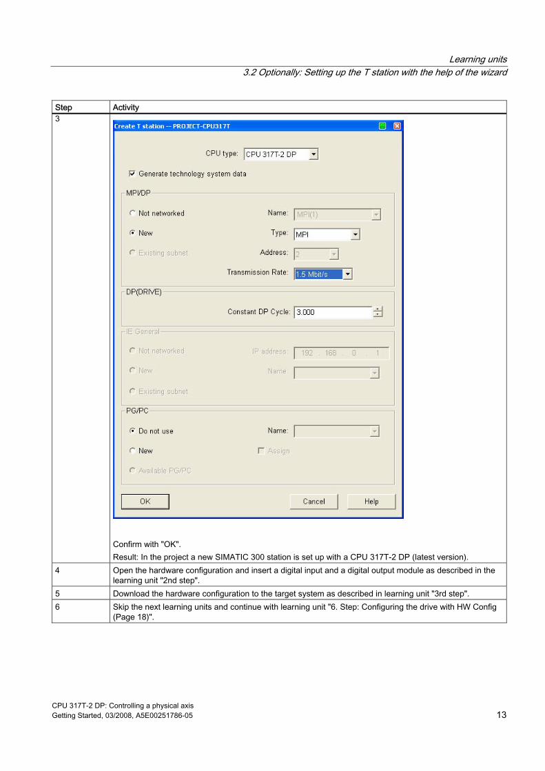
Step Activity 3
Confirm with "OK". Result: In the project a new SIMATIC 300 station is set up with a CPU 317T-2 DP (latest version).
4 Open the hardware configuration and insert a digital input and a digital output module as described in the learning unit "2nd step".
5 Download the hardware configuration to the target system as described in learning unit "3rd step". 6 Skip the next learning units and continue with learning unit "6. Step: Configuring the drive with HW Config
(Page 18)".
Learning units 3.3 2. Step: Configuring the CPU 317T-2 DP in HW -Config
CPU 317T-2 DP: Controlling a physical axis 14 Getting Started, 03/2008, A5E00251786-05
3.3 2. Step: Configuring the CPU 317T-2 DP in HW -Config
Procedure Step Activity Result 1 Set up a new project in the SIMATIC Manager (e.g. "Getting Started
CPU 317T") Select the Insert > Station > SIMATIC 300 Station menu command to insert a SIMATIC 300 station.
The SIMATIC 300 station appears in SIMATIC Manager.
2 Open HW Config by selecting the "SIMATIC 300" station and double-clicking "Hardware".
HW Config opens.
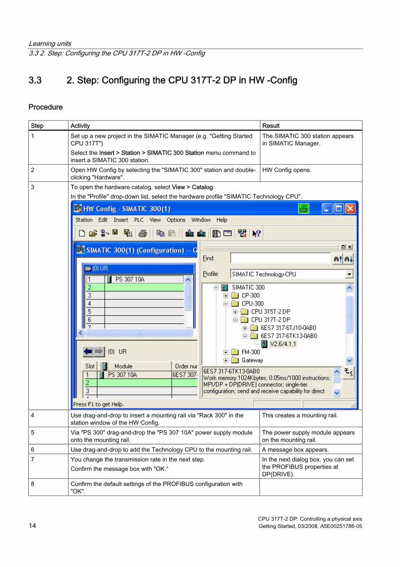
3 To open the hardware catalog, select View > Catalog. In the "Profile" drop-down list, select the hardware profile "SIMATIC Technology CPU".
4 Use drag-and-drop to insert a mounting rail via "Rack 300" in the station window of the HW Config.
This creates a mounting rail.
5 Via "PS 300" drag-and-drop the "PS 307 10A" power supply module onto the mounting rail.
The power supply module appears on the mounting rail.
6 Use drag-and-drop to add the Technology CPU to the mounting rail. A message box appears. 7 You change the transmission rate in the next step.
Confirm the message box with "OK.“ In the next dialog box, you can set the PROFIBUS properties at DP(DRIVE).
8 Confirm the default settings of the PROFIBUS configuration with "OK".
Learning units 3.3 2. Step: Configuring the CPU 317T-2 DP in HW -Config
CPU 317T-2 DP: Controlling a physical axis Getting Started, 03/2008, A5E00251786-05 15
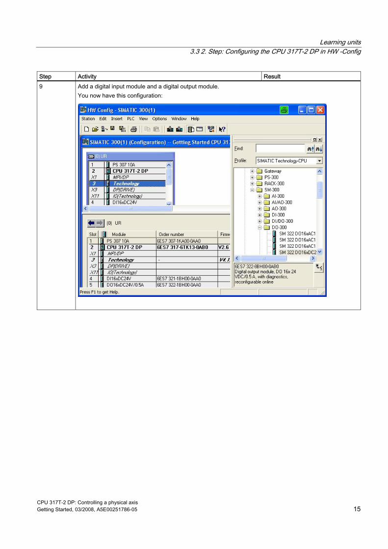
Step Activity Result 9 Add a digital input module and a digital output module.
You now have this configuration:
Learning units 3.4 3. Step: Changing the transmission rate at the MPI/DP interface
CPU 317T-2 DP: Controlling a physical axis 16 Getting Started, 03/2008, A5E00251786-05
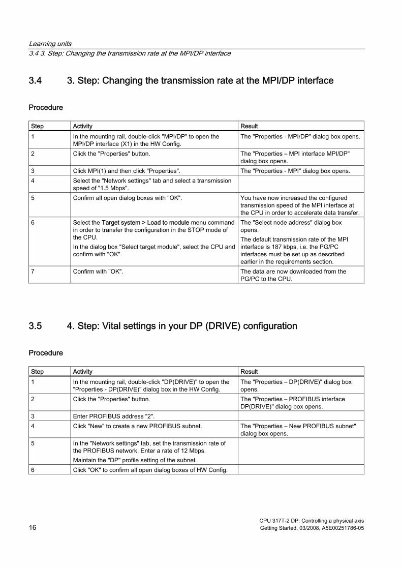
3.4 3. Step: Changing the transmission rate at the MPI/DP interface
Procedure Step Activity Result 1 In the mounting rail, double-click "MPI/DP" to open the
MPI/DP interface (X1) in the HW Config. The "Properties - MPI/DP" dialog box opens.
2 Click the "Properties" button. The "Properties – MPI interface MPI/DP" dialog box opens.
3 Click MPI(1) and then click "Properties". The "Properties - MPI" dialog box opens. 4 Select the "Network settings" tab and select a transmission
speed of "1.5 Mbps".
5 Confirm all open dialog boxes with "OK". You have now increased the configured transmission speed of the MPI interface at the CPU in order to accelerate data transfer.
6 Select the Target system > Load to module menu command in order to transfer the configuration in the STOP mode of the CPU. In the dialog box "Select target module", select the CPU and confirm with "OK".
The "Select node address" dialog box opens. The default transmission rate of the MPI interface is 187 kbps, i.e. the PG/PC interfaces must be set up as described earlier in the requirements section.
7 Confirm with "OK". The data are now downloaded from the PG/PC to the CPU.
3.5 4. Step: Vital settings in your DP (DRIVE) configuration
Procedure Step Activity Result 1 In the mounting rail, double-click "DP(DRIVE)" to open the
"Properties - DP(DRIVE)" dialog box in the HW Config. The "Properties – DP(DRIVE)" dialog box opens.
2 Click the "Properties" button. The "Properties – PROFIBUS interface DP(DRIVE)" dialog box opens.
3 Enter PROFIBUS address "2". 4 Click "New" to create a new PROFIBUS subnet. The "Properties – New PROFIBUS subnet"
dialog box opens. 5 In the "Network settings" tab, set the transmission rate of
the PROFIBUS network. Enter a rate of 12 Mbps. Maintain the "DP" profile setting of the subnet.
6 Click "OK" to confirm all open dialog boxes of HW Config.
Learning units 3.6 5. Step: Generating technology system data
CPU 317T-2 DP: Controlling a physical axis Getting Started, 03/2008, A5E00251786-05 17
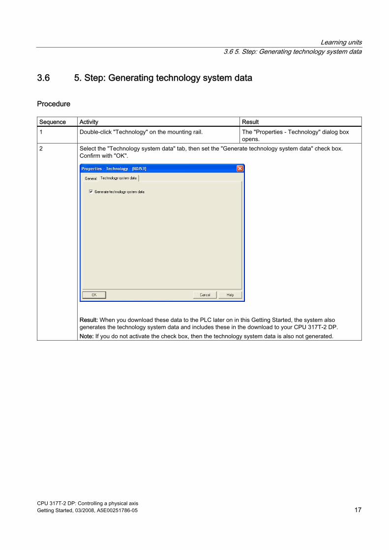
3.6 5. Step: Generating technology system data
Procedure Sequence Activity Result 1 Double-click "Technology" on the mounting rail. The "Properties - Technology" dialog box
opens. 2 Select the "Technology system data" tab, then set the "Generate technology system data" check box.
Confirm with "OK".
Result: When you download these data to the PLC later on in this Getting Started, the system also generates the technology system data and includes these in the download to your CPU 317T-2 DP. Note: If you do not activate the check box, then the technology system data is also not generated.
Learning units 3.7 6. Step: Configuring the drive with HW Config
CPU 317T-2 DP: Controlling a physical axis 18 Getting Started, 03/2008, A5E00251786-05
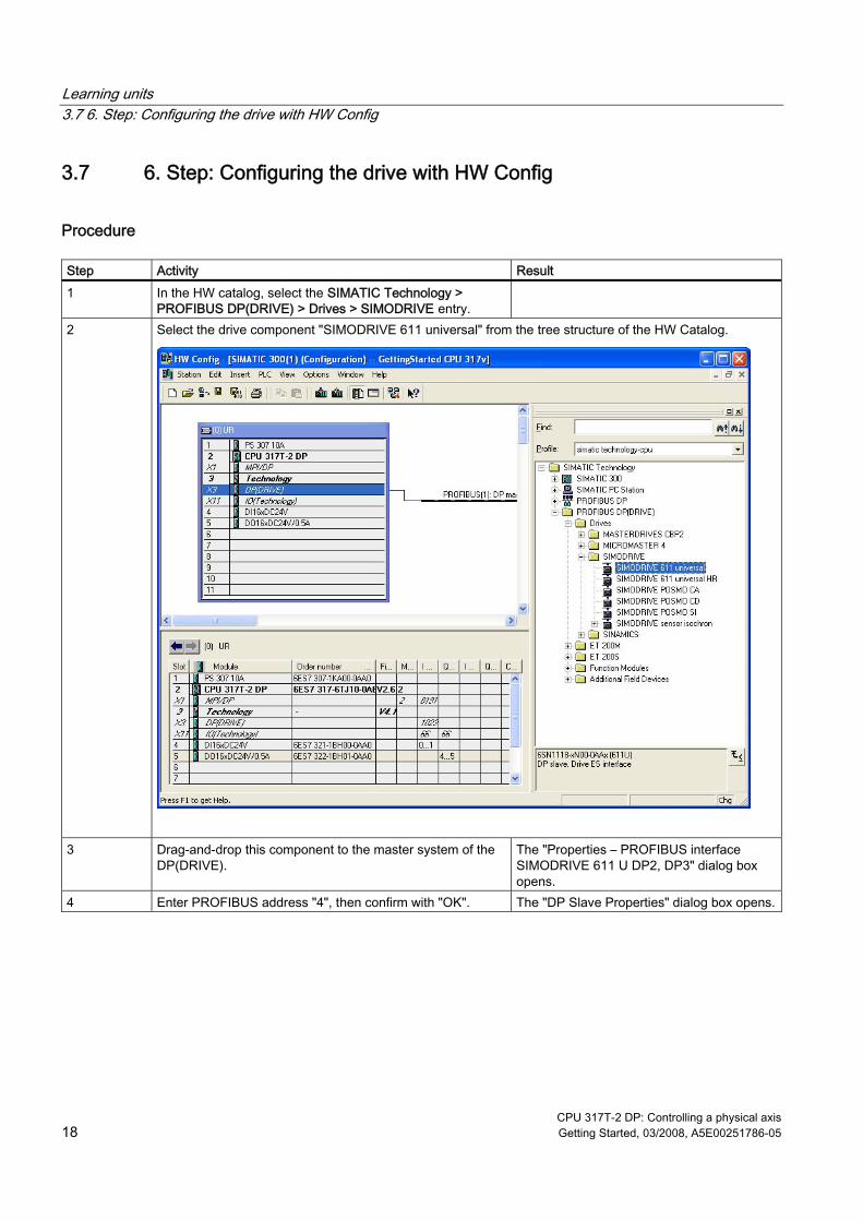
3.7 6. Step: Configuring the drive with HW Config
Procedure Step Activity Result 1 In the HW catalog, select the SIMATIC Technology >
PROFIBUS DP(DRIVE) > Drives > SIMODRIVE entry.
2 Select the drive component "SIMODRIVE 611 universal" from the tree structure of the HW Catalog.
3 Drag-and-drop this component to the master system of the DP(DRIVE).
The "Properties – PROFIBUS interface SIMODRIVE 611 U DP2, DP3" dialog box opens.
4 Enter PROFIBUS address "4", then confirm with "OK". The "DP Slave Properties" dialog box opens.
Learning units 3.7 6. Step: Configuring the drive with HW Config
CPU 317T-2 DP: Controlling a physical axis Getting Started, 03/2008, A5E00251786-05 19
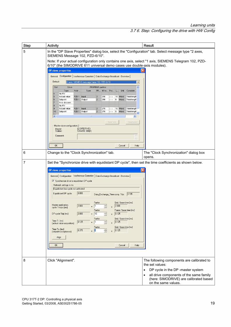
Step Activity Result 5 In the "DP Slave Properties" dialog box, select the "Configuration" tab. Select message type "2 axes,
SIEMENS Message 102, PZD-6/10". Note: If your actual configuration only contains one axis, select "1 axis, SIEMENS Telegram 102, PZD-6/10" (the SIMODRIVE 611 universal demo cases use double-axis modules).
6 Change to the "Clock Synchronization" tab. The "Clock Synchronization" dialog box
opens. 7 Set the "Synchronize drive with equidistant DP cycle", then set the time coefficients as shown below.
8 Click "Alignment". The following components are calibrated to the set values: • DP cycle in the DP -master system • all drive components of the same family
(here: SIMODRIVE) are calibrated based on the same values.
Learning units 3.8 7. Step: Configuring the axis(axes) with S7T Config
CPU 317T-2 DP: Controlling a physical axis 20 Getting Started, 03/2008, A5E00251786-05
Step Activity Result 9 Confirm with "OK". 10 In the HW Config, select the Station > Save and Compile
menu command in order to close the HW Config. The system compiles your project, and adds the "Technological Objects" object to the project window in SIMATIC Manager.
3.8 7. Step: Configuring the axis(axes) with S7T Config
Important information In this step, you create your technology objects (e.g. axes) with S7T Config. Use "Technology Objects Management" to generate a technology DB for each TO. Do not copy the technology DBs in order to ensure a defined assignment between the technology DB and its TO.
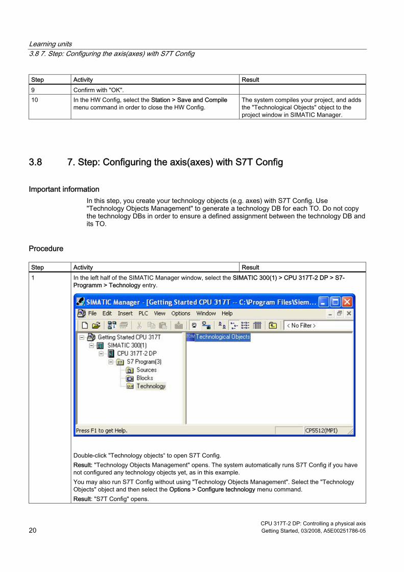
Procedure Step Activity Result 1 In the left half of the SIMATIC Manager window, select the SIMATIC 300(1) > CPU 317T-2 DP > S7-
Programm > Technology entry.
Double-click "Technology objects“ to open S7T Config. Result: "Technology Objects Management" opens. The system automatically runs S7T Config if you have not configured any technology objects yet, as in this example. You may also run S7T Config without using "Technology Objects Management". Select the "Technology Objects" object and then select the Options > Configure technology menu command. Result: "S7T Config" opens.
Learning units 3.8 7. Step: Configuring the axis(axes) with S7T Config
CPU 317T-2 DP: Controlling a physical axis Getting Started, 03/2008, A5E00251786-05 21
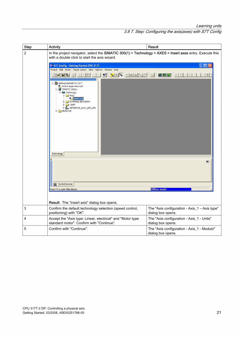
Step Activity Result 2 In the project navigator, select the SIMATIC 300(1) > Technology > AXES > Insert axes entry. Execute this
with a double click to start the axis wizard.
Result: The “Insert axis" dialog box opens.
3 Confirm the default technology selection (speed control, positioning) with "OK".
The "Axis configuration - Axis_1 – Axis type" dialog box opens.
4 Accept the "Axis type: Linear, electrical" and "Motor type: standard motor". Confirm with "Continue".
The "Axis configuration - Axis_1 - Units" dialog box opens.
5 Confirm with "Continue". The "Axis configuration - Axis_1 - Modulo" dialog box opens.
Learning units 3.8 7. Step: Configuring the axis(axes) with S7T Config
CPU 317T-2 DP: Controlling a physical axis 22 Getting Started, 03/2008, A5E00251786-05
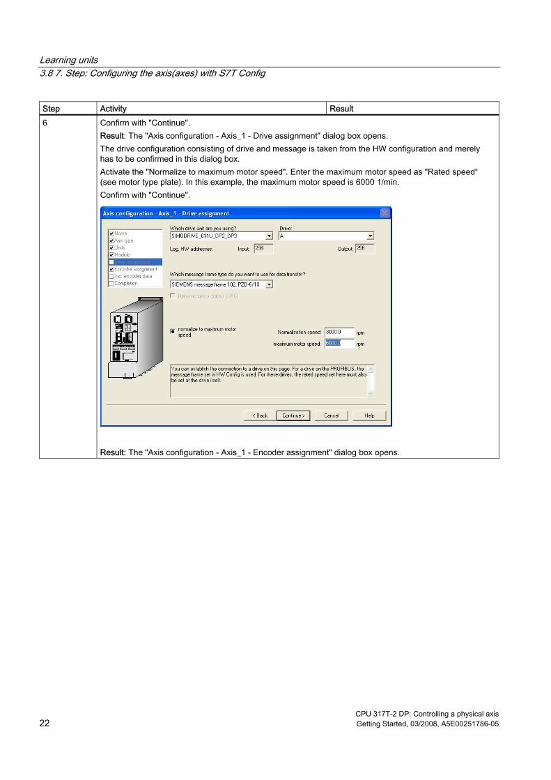
Step Activity Result 6 Confirm with "Continue".
Result: The "Axis configuration - Axis_1 - Drive assignment" dialog box opens. The drive configuration consisting of drive and message is taken from the HW configuration and merely has to be confirmed in this dialog box. Activate the "Normalize to maximum motor speed". Enter the maximum motor speed as "Rated speed“ (see motor type plate). In this example, the maximum motor speed is 6000 1/min. Confirm with "Continue".
Result: The "Axis configuration - Axis_1 - Encoder assignment" dialog box opens.
Learning units 3.8 7. Step: Configuring the axis(axes) with S7T Config
CPU 317T-2 DP: Controlling a physical axis Getting Started, 03/2008, A5E00251786-05 23
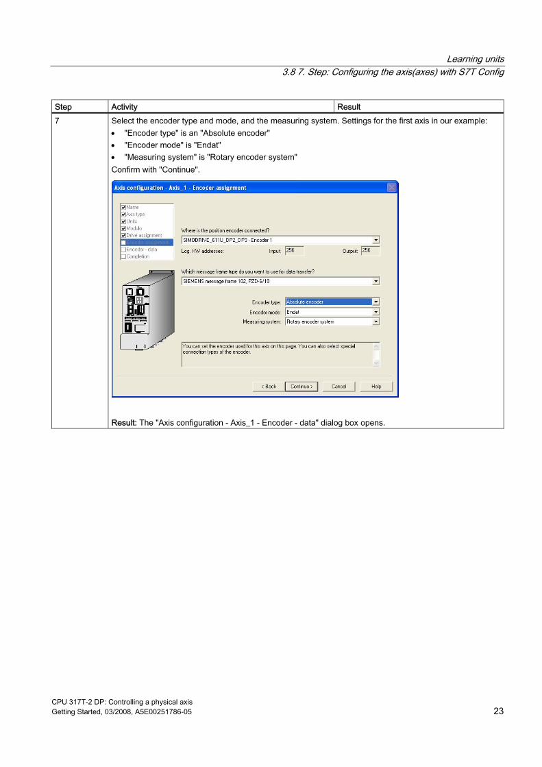
Step Activity Result 7 Select the encoder type and mode, and the measuring system. Settings for the first axis in our example:
• "Encoder type" is an "Absolute encoder" • "Encoder mode" is "Endat" • "Measuring system" is "Rotary encoder system" Confirm with "Continue".
Result: The "Axis configuration - Axis_1 - Encoder - data" dialog box opens.
Learning units 3.8 7. Step: Configuring the axis(axes) with S7T Config
CPU 317T-2 DP: Controlling a physical axis 24 Getting Started, 03/2008, A5E00251786-05
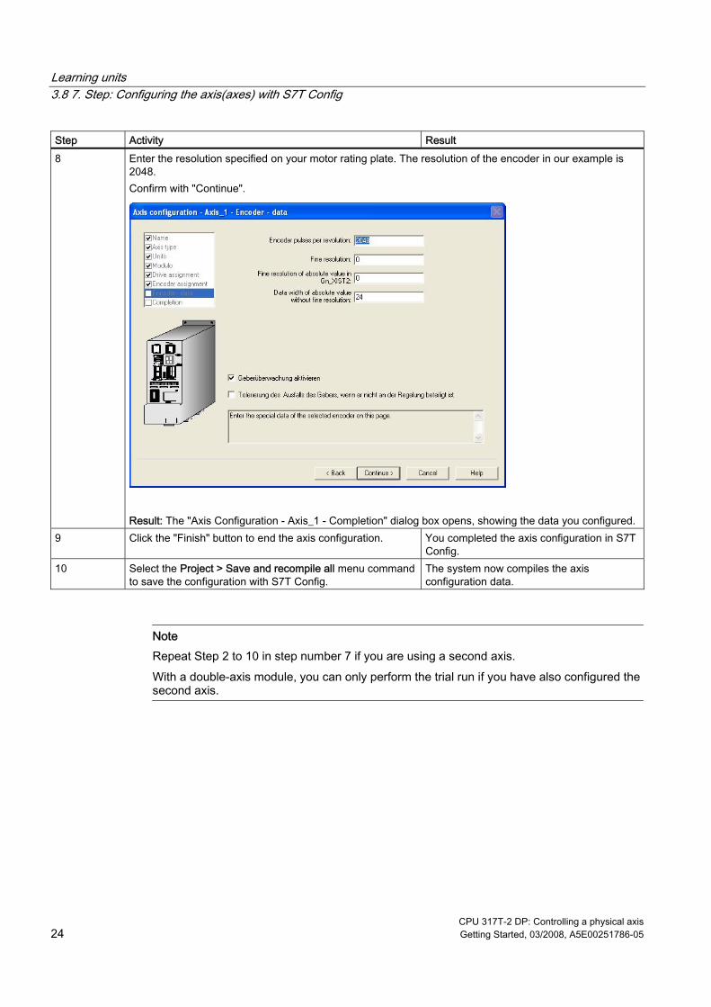
Step Activity Result 8 Enter the resolution specified on your motor rating plate. The resolution of the encoder in our example is
2048. Confirm with "Continue".
Result: The "Axis Configuration - Axis_1 - Completion" dialog box opens, showing the data you configured.
9 Click the "Finish" button to end the axis configuration. You completed the axis configuration in S7T Config.
10 Select the Project > Save and recompile all menu command to save the configuration with S7T Config.
The system now compiles the axis configuration data.
Note Repeat Step 2 to 10 in step number 7 if you are using a second axis. With a double-axis module, you can only perform the trial run if you have also configured the second axis.
Learning units 3.9 8. Step: Creating the technology DBs
CPU 317T-2 DP: Controlling a physical axis Getting Started, 03/2008, A5E00251786-05 25
3.9 8. Step: Creating the technology DBs
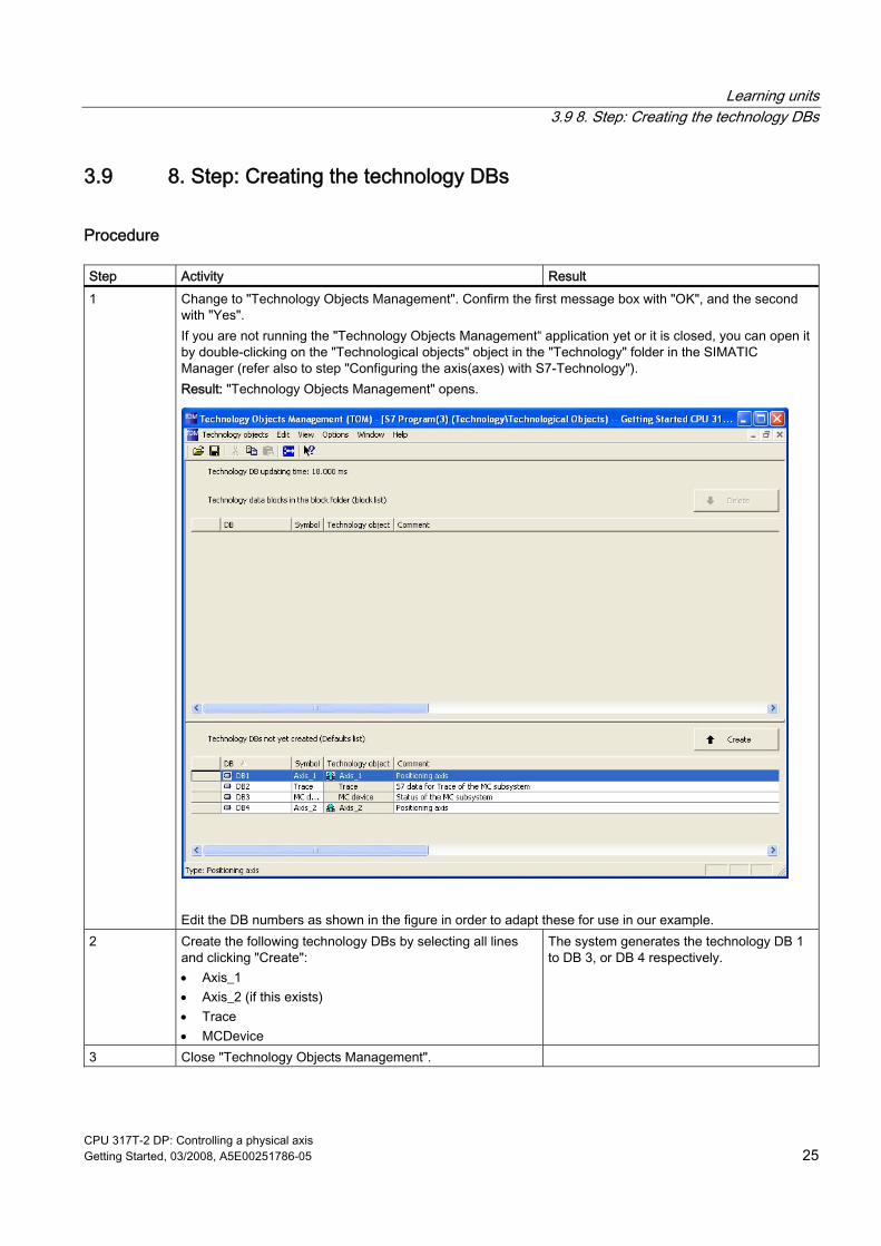
Procedure Step Activity Result 1 Change to "Technology Objects Management". Confirm the first message box with "OK", and the second
with "Yes". If you are not running the "Technology Objects Management“ application yet or it is closed, you can open it by double-clicking on the "Technological objects" object in the "Technology" folder in the SIMATIC Manager (refer also to step "Configuring the axis(axes) with S7-Technology"). Result: "Technology Objects Management" opens.
Edit the DB numbers as shown in the figure in order to adapt these for use in our example.
2 Create the following technology DBs by selecting all lines and clicking "Create": • Axis_1 • Axis_2 (if this exists) • Trace • MCDevice
The system generates the technology DB 1 to DB 3, or DB 4 respectively.
3 Close "Technology Objects Management".
Learning units 3.10 9. Step: Configuring the drive with SimoComU
CPU 317T-2 DP: Controlling a physical axis 26 Getting Started, 03/2008, A5E00251786-05
Step Activity Result 4 In the SIMATIC Manager, select the Options > Set PG/PC
interface menu command in order to change the MPI transmission rate to 1.5 Mbit/s.
5 Select the MPI interface. Click the properties and then change the transmission speed and confirm all open dialog boxes with "OK".
6 In the left half of the SIMATIC Manager window, select the SIMATIC 300(1) > CPU 317T-2 DP > S7-Programm > Blocks entry.
7 Select the Target system > Load menu command in order to load the blocks and the system data to the CPU.
8 Confirm the message box • Download system data • Overwrite existing system data
The system data blocks are downloaded to the CPU. The initial download of your SDBs may take longer (up to a few minutes), because of their larger data volume.
3.10 9. Step: Configuring the drive with SimoComU
Procedure Step Activity Result 1 Connect SIMODRIVE 611U to the serial interface of your
PG/PC.
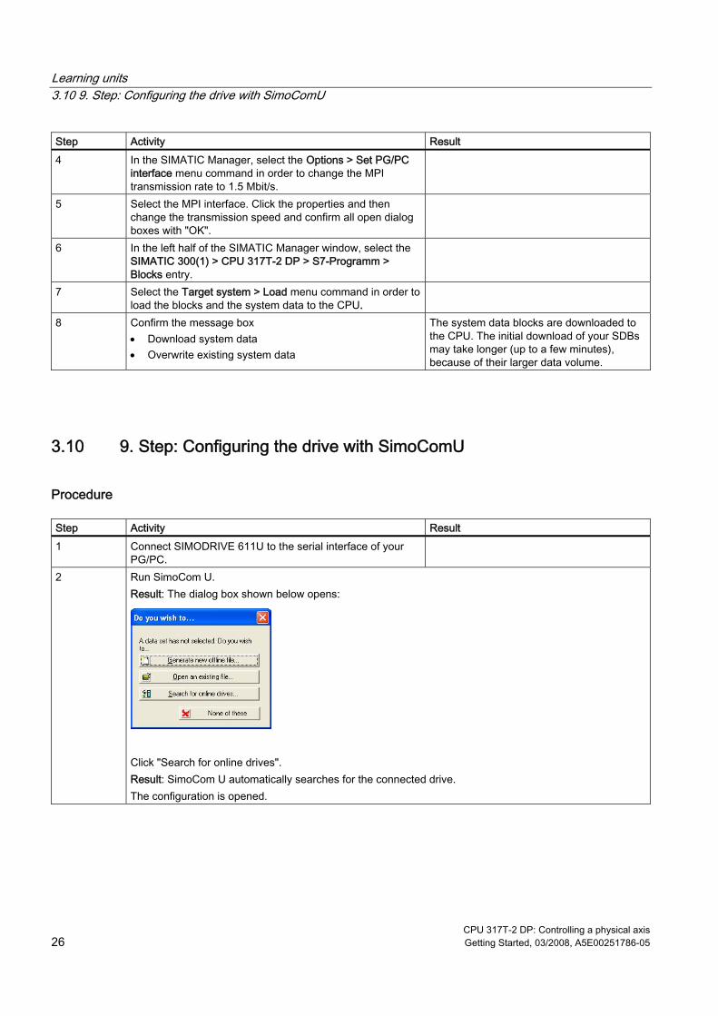
2 Run SimoCom U. Result: The dialog box shown below opens:
Click "Search for online drives". Result: SimoCom U automatically searches for the connected drive. The configuration is opened.
Learning units 3.10 9. Step: Configuring the drive with SimoComU
CPU 317T-2 DP: Controlling a physical axis Getting Started, 03/2008, A5E00251786-05 27
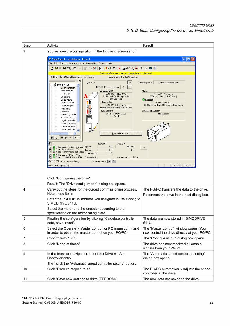
Step Activity Result 3 You will see the configuration in the following screen shot.
Click "Configuring the drive". Result: The "Drive configuration" dialog box opens.
4 Carry out the steps for the guided commissioning process. Note these items: Enter the PROFIBUS address you assigned in HW Config to SIMODRIVE 611U. Select the motor and the encoder according to the specification on the motor rating plate.
The PG/PC transfers the data to the drive. Reconnect the drive in the next dialog box.
5 Finalize the configuration by clicking "Calculate controller data, save, reset".
The data are now stored in SIMODRIVE 611U.
6 Select the Operate > Master control for PC menu command in order to obtain the master control on your PG/PC.
The "Master control" window opens. You now control the drive directly at your PG/PC.
7 Confirm with "OK". The "Continue with..." dialog box opens. 8 Click "None of these". The drive has now received all enable
signals from your PG/PC. 9 In the browser (navigator), select the Drive A - A >
Controller entry. Then click the "Automatic speed controller setting" button.
The "Automatic speed controller setting" dialog box opens.
10 Click "Execute steps 1 to 4". The PG/PC automatically adjusts the speed controller at the drive.
11 Click "Save new settings to drive (FEPROM)". The new data are saved to the drive.
Learning units 3.10 9. Step: Configuring the drive with SimoComU
CPU 317T-2 DP: Controlling a physical axis 28 Getting Started, 03/2008, A5E00251786-05
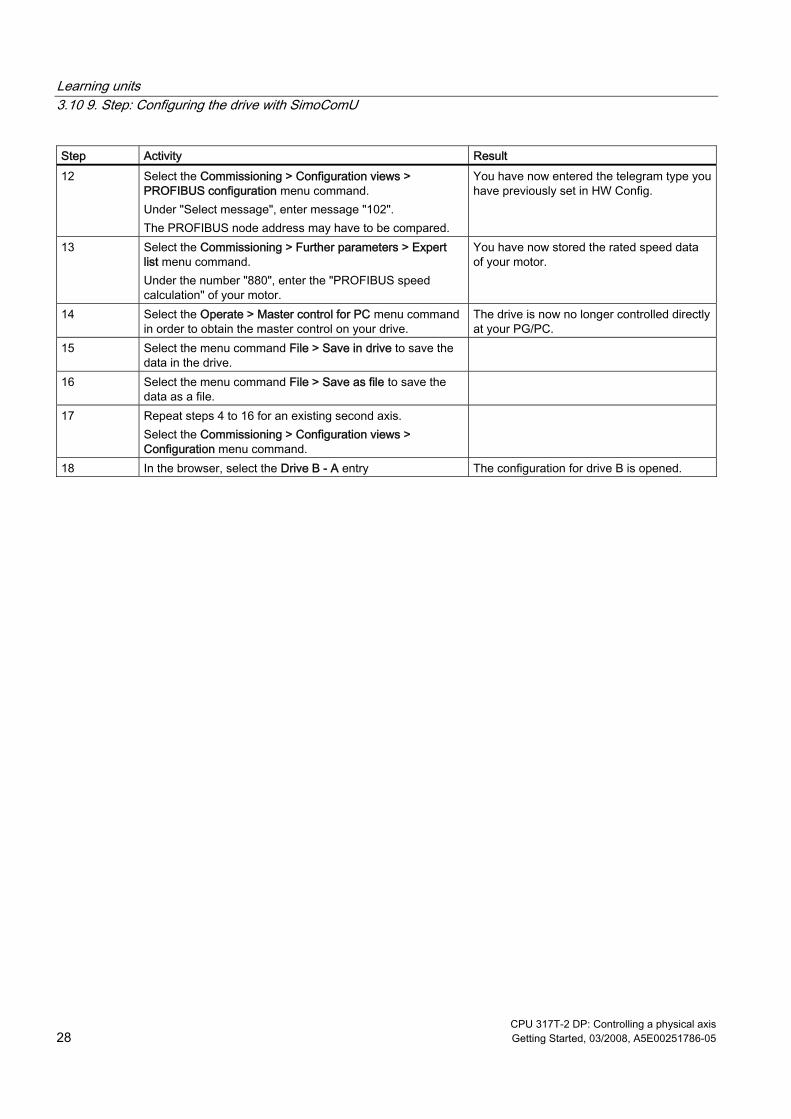
Step Activity Result 12 Select the Commissioning > Configuration views >
PROFIBUS configuration menu command. Under "Select message", enter message "102". The PROFIBUS node address may have to be compared.
You have now entered the telegram type you have previously set in HW Config.
13 Select the Commissioning > Further parameters > Expert list menu command. Under the number "880", enter the "PROFIBUS speed calculation" of your motor.
You have now stored the rated speed data of your motor.
14 Select the Operate > Master control for PC menu command in order to obtain the master control on your drive.
The drive is now no longer controlled directly at your PG/PC.
15 Select the menu command File > Save in drive to save the data in the drive.
16 Select the menu command File > Save as file to save the data as a file.
17 Repeat steps 4 to 16 for an existing second axis. Select the Commissioning > Configuration views > Configuration menu command.
18 In the browser, select the Drive B - A entry The configuration for drive B is opened.
Learning units 3.11 10. Step: Controlling the axis with the STEP 7 user program
CPU 317T-2 DP: Controlling a physical axis Getting Started, 03/2008, A5E00251786-05 29
3.11 10. Step: Controlling the axis with the STEP 7 user program
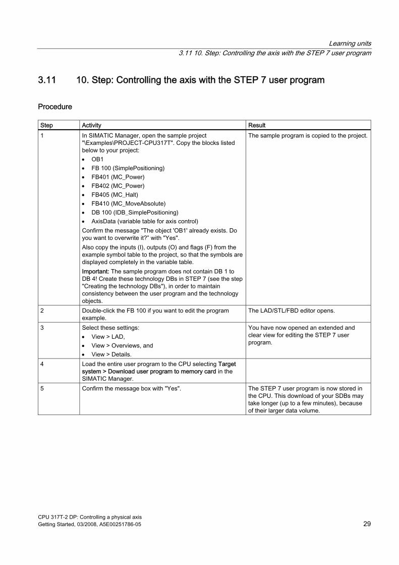
Procedure Step Activity Result 1 In SIMATIC Manager, open the sample project
"\Examples\PROJECT-CPU317T". Copy the blocks listed below to your project: • OB1 • FB 100 (SimplePositioning) • FB401 (MC_Power) • FB402 (MC_Power) • FB405 (MC_Halt) • FB410 (MC_MoveAbsolute) • DB 100 (IDB_SimplePositioning) • AxisData (variable table for axis control) Confirm the message "The object 'OB1' already exists. Do you want to overwrite it?” with "Yes". Also copy the inputs (I), outputs (O) and flags (F) from the example symbol table to the project, so that the symbols are displayed completely in the variable table. Important: The sample program does not contain DB 1 to DB 4! Create these technology DBs in STEP 7 (see the step "Creating the technology DBs"), in order to maintain consistency between the user program and the technology objects.
The sample program is copied to the project.
2 Double-click the FB 100 if you want to edit the program example.
The LAD/STL/FBD editor opens.
3 Select these settings: • View > LAD, • View > Overviews, and • View > Details.
You have now opened an extended and clear view for editing the STEP 7 user program.
4 Load the entire user program to the CPU selecting Target system > Download user program to memory card in the SIMATIC Manager.
5 Confirm the message box with "Yes". The STEP 7 user program is now stored in the CPU. This download of your SDBs may take longer (up to a few minutes), because of their larger data volume.
Learning units 3.12 11. Step: Trial run
CPU 317T-2 DP: Controlling a physical axis 30 Getting Started, 03/2008, A5E00251786-05
3.12 11. Step: Trial run
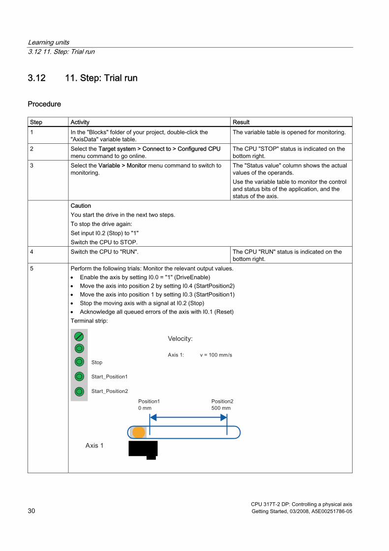
Procedure Step Activity Result 1 In the "Blocks" folder of your project, double-click the
"AxisData" variable table. The variable table is opened for monitoring.
2 Select the Target system > Connect to > Configured CPU menu command to go online.
The CPU "STOP" status is indicated on the bottom right.
3 Select the Variable > Monitor menu command to switch to monitoring.
The "Status value" column shows the actual values of the operands. Use the variable table to monitor the control and status bits of the application, and the status of the axis.
Caution You start the drive in the next two steps. To stop the drive again: Set input I0.2 (Stop) to "1" Switch the CPU to STOP.
4 Switch the CPU to "RUN". The CPU "RUN" status is indicated on the bottom right.
5 Perform the following trials: Monitor the relevant output values. • Enable the axis by setting I0.0 = "1" (DriveEnable) • Move the axis into position 2 by setting I0.4 (StartPosition2) • Move the axis into position 1 by setting I0.3 (StartPosition1) • Stop the moving axis with a signal at I0.2 (Stop) • Acknowledge all queued errors of the axis with I0.1 (Reset) Terminal strip:
CPU 317T-2 DP: Controlling a physical axis Getting Started, 03/2008, A5E00251786-05 31
Further information 4Diagnostics / correction of errors
Incorrect operator input, faulty wiring or inconsistent configuration data may lead to errors. For information on how to analyze such errors and messages, refer to the S7-Technology manual.
Service and support on the Internet In addition to our documentation, we offer a comprehensive online knowledge base on the Internet at: http://www.siemens.com/automation/service&support There you will find: ● The newsletter that provides you with latest information relating to your product ● Your appropriate documentation, using our Service & Support search engine ● A bulletin board in which users and specialists worldwide exchange their know-how ● Your local Siemens partner for Automation & Drives in our Partner database ● Information about local service, repairs, and spare parts. You will find much more under
"Services".

Further information
CPU 317T-2 DP: Controlling a physical axis 32 Getting Started, 03/2008, A5E00251786-05