Embed Size (px)
Citation preview
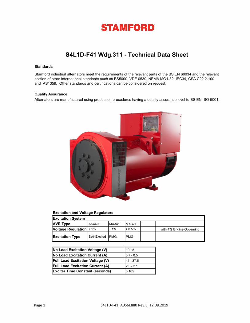
Standards
Quality Assurance
Excitation and Voltage Regulators
AVR Type AS440 MX341 MX321Voltage Regulation ± 1% ± 1% ± 0.5%
Excitation Type Self-Excited PMG PMG
Exciter Time Constant (seconds)
10 - 80.7 - 0.541 - 37.52.3 - 2.10.105
No Load Excitation Voltage (V)No Load Excitation Current (A)Full Load Excitation Voltage (V)Full Load Excitation Current (A)
Alternators are manufactured using production procedures having a quality assurance level to BS EN ISO 9001.
Stamford industrial alternators meet the requirements of the relevant parts of the BS EN 60034 and the relevant section of other international standards such as BS5000, VDE 0530, NEMA MG1-32, IEC34, CSA C22.2-100 and AS1359. Other standards and certifications can be considered on request.
S4L1D-F41 Wdg.311 - Technical Data Sheet
with 4% Engine Governing
Excitation System
Page 1 S4L1D-F41_A056E880 Rev.E_12.08.2019
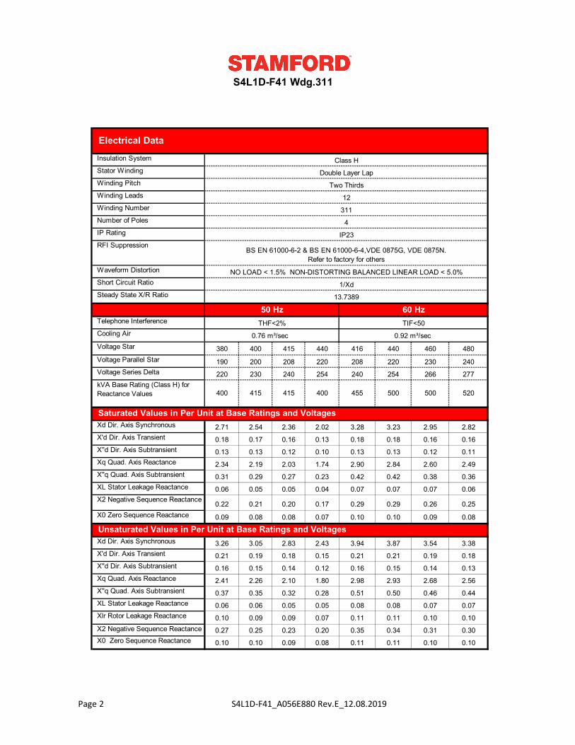
380 400 415 440 416 440 460 480
190 200 208 220 208 220 230 240
220 230 240 254 240 254 266 277
2.71 2.54 2.36 2.02 3.28 3.23 2.95 2.82
0.18 0.17 0.16 0.13 0.18 0.18 0.16 0.16
0.13 0.13 0.12 0.10 0.13 0.13 0.12 0.11
2.34 2.19 2.03 1.74 2.90 2.84 2.60 2.49
0.31 0.29 0.27 0.23 0.42 0.42 0.38 0.36
0.06 0.05 0.05 0.04 0.07 0.07 0.07 0.06
0.22 0.21 0.20 0.17 0.29 0.29 0.26 0.25
0.09 0.08 0.08 0.07 0.10 0.10 0.09 0.08
3.26 3.05 2.83 2.43 3.94 3.87 3.54 3.38
0.21 0.19 0.18 0.15 0.21 0.21 0.19 0.18
0.16 0.15 0.14 0.12 0.16 0.15 0.14 0.13
2.41 2.26 2.10 1.80 2.98 2.93 2.68 2.56
0.37 0.35 0.32 0.28 0.51 0.50 0.46 0.44
0.06 0.06 0.05 0.05 0.08 0.08 0.07 0.07
0.10 0.09 0.09 0.07 0.11 0.11 0.10 0.10
0.27 0.25 0.23 0.20 0.35 0.34 0.31 0.30
0.10 0.10 0.09 0.08 0.11 0.11 0.10 0.10
S4L1D-F41 Wdg.311
Electrical Data Insulation System Class H Stator Winding Double Layer Lap Winding Pitch Two Thirds Winding Leads 12 Winding Number 311 Number of Poles 4 IP Rating IP23 RFI Suppression
BS EN 61000-6-2 & BS EN 61000-6-4,VDE 0875G, VDE 0875N. Refer to factory for others
Cooling Air 0.76 m³/sec 0.92 m³/sec
Waveform Distortion NO LOAD < 1.5% NON-DISTORTING BALANCED LINEAR LOAD < 5.0% Short Circuit Ratio 1/Xd Steady State X/R Ratio 13.7389
50 Hz 60 Hz Telephone Interference THF<2% TIF<50
Xq Quad. Axis Reactance
Voltage Star
kVA Base Rating (Class H) for Reactance Values 400 415 415 400 455 500 500 520
Saturated Values in Per Unit at Base Ratings and Voltages Xd Dir. Axis Synchronous
X'd Dir. Axis Transient
X''d Dir. Axis Subtransient
Xd Dir. Axis Synchronous
X''q Quad. Axis Subtransient
XL Stator Leakage Reactance
X2 Negative Sequence Reactance
X0 Zero Sequence Reactance
Unsaturated Values in Per Unit at Base Ratings and Voltages
Voltage Parallel Star
Voltage Series Delta
X'd Dir. Axis Transient
X''d Dir. Axis Subtransient
Xq Quad. Axis Reactance
X''q Quad. Axis Subtransient
XL Stator Leakage Reactance
Xlr Rotor Leakage Reactance
X2 Negative Sequence Reactance X0 Zero Sequence Reactance
Page 2 S4L1D-F41_A056E880 Rev.E_12.08.2019
SG1.0
SG1.2
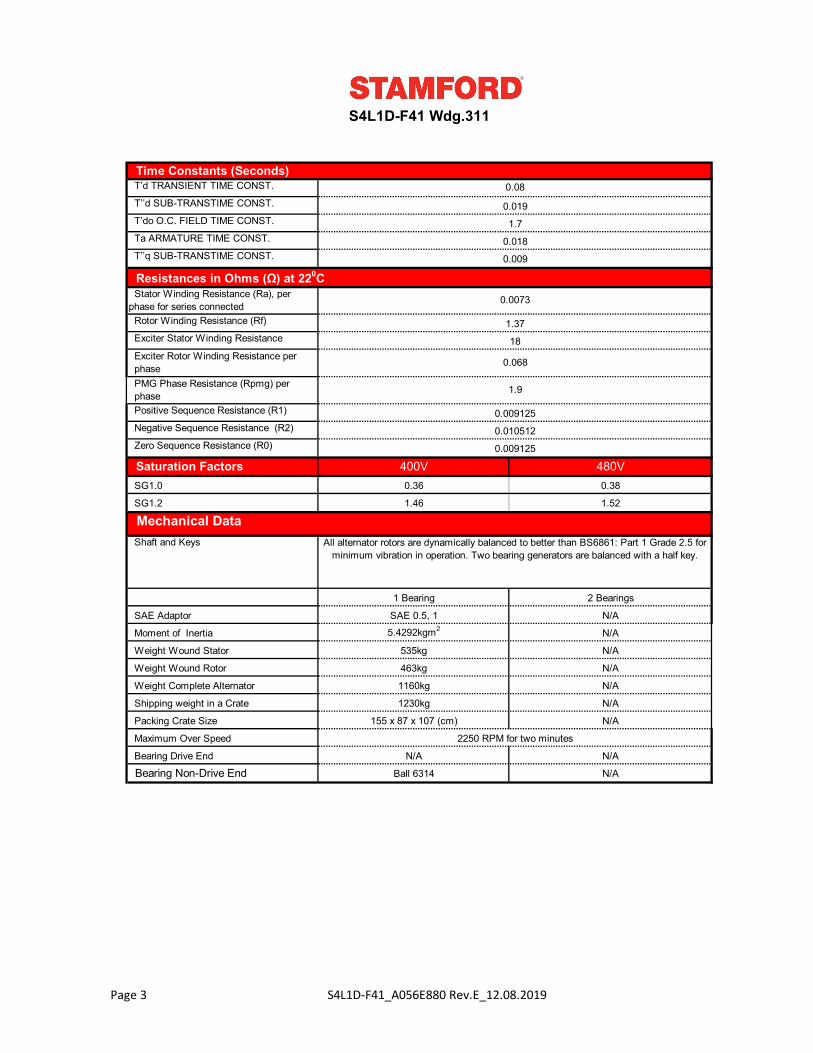
Ball 6314
S4L1D-F41 Wdg.311
N/A
N/A155 x 87 x 107 (cm)
2250 RPM for two minutes
1230kg
0.08
0.010512
0.009125
0.36 0.38
1.46 1.52
All alternator rotors are dynamically balanced to better than BS6861: Part 1 Grade 2.5 for minimum vibration in operation. Two bearing generators are balanced with a half key.
N/A N/A
N/A
Weight Wound Rotor
Weight Complete Alternator
Shipping weight in a Crate
Packing Crate Size
Maximum Over Speed
Bearing Drive End
Bearing Non-Drive End
SAE Adaptor SAE 0.5, 1 N/A
0.009125
1 Bearing 2 Bearings
1160kg N/A
5.4292kgm2 N/A
535kg N/A
N/A463kg
Moment of Inertia
Weight Wound Stator
Shaft and Keys
0.018
0.009
1.9
0.019
1.7
0.0073
1.37
Exciter Rotor Winding Resistance per phase PMG Phase Resistance (Rpmg) per phase Positive Sequence Resistance (R1)
Negative Sequence Resistance (R2)
Zero Sequence Resistance (R0)
Mechanical Data
Time Constants (Seconds)
Resistances in Ohms (Ω) at 220C Stator Winding Resistance (Ra), per phase for series connected Rotor Winding Resistance (Rf)
Exciter Stator Winding Resistance
T’d TRANSIENT TIME CONST.
T’’d SUB-TRANSTIME CONST.
T’do O.C. FIELD TIME CONST.
Ta ARMATURE TIME CONST.
T’’q SUB-TRANSTIME CONST.
Saturation Factors
18
0.068
400V 480V
Page 3 S4L1D-F41_A056E880 Rev.E_12.08.2019
S4L1D-F41 Wdg.311
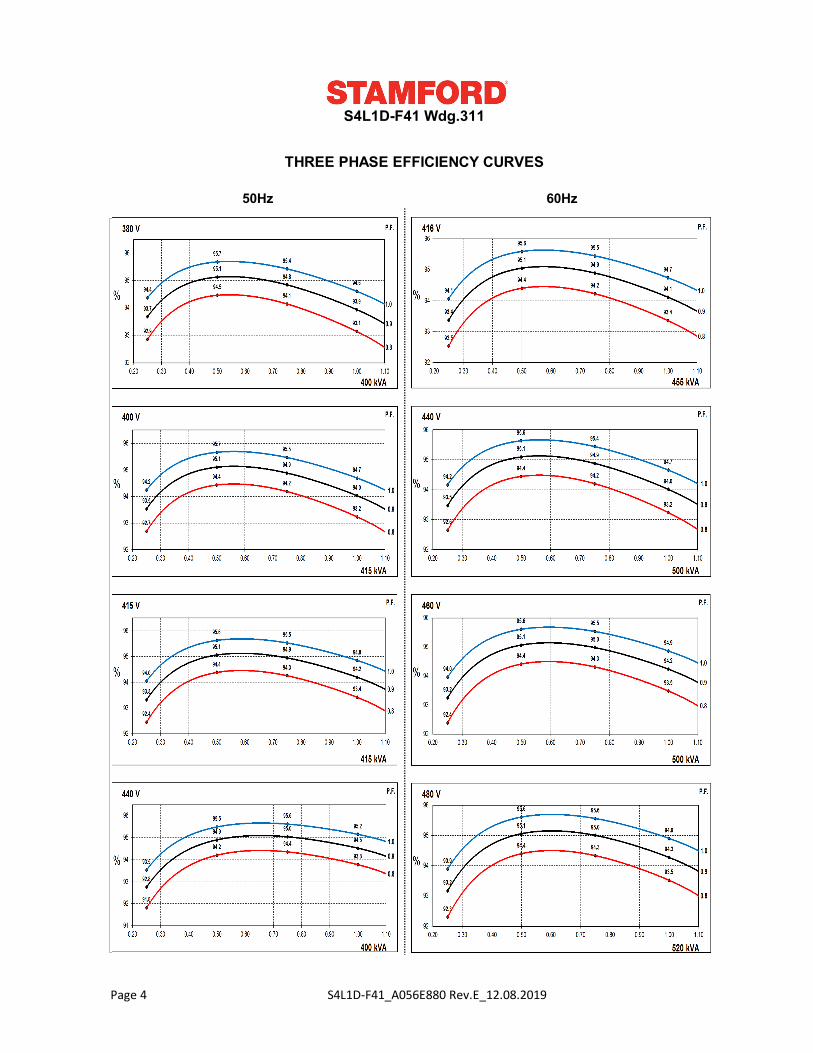
THREE PHASE EFFICIENCY CURVES
50Hz 60Hz
insert curves of 50Hz insert curves of 60Hz
Page 4 S4L1D-F41_A056E880 Rev.E_12.08.2019
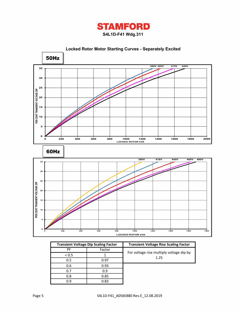
0.8 0.850.9 0.83
For voltage rise multiply voltage dip by 1.250.5 0.97
0.6 0.930.7 0.9
PF Factor< 0.5 1
Locked Rotor Motor Starting Curves - Separately Excited
S4L1D-F41 Wdg.311
Transient Voltage Dip Scaling Factor Transient Voltage Rise Scaling Factor
50Hz
60Hz
insert curve
insert curve
380V 400V 415V 440V
0
5
10
15
20
25
30
35
0 200 400 600 800 1000 1200 1400 1600 1800 2000
PER C
ENT T
RANS
IENT V
OLTA
GE D
IP
LOCKED ROTOR kVA
380V 416V 440V 460V 480V
0
5
10
15
20
25
30
35
0 200 400 600 800 1000 1200 1400 1600 1800
PER C
ENT T
RANS
IENT V
OLTA
GE D
IP
LOCKED ROTOR kVA
Page 5 S4L1D-F41_A056E880 Rev.E_12.08.2019
S4L1D-F41 Wdg.311
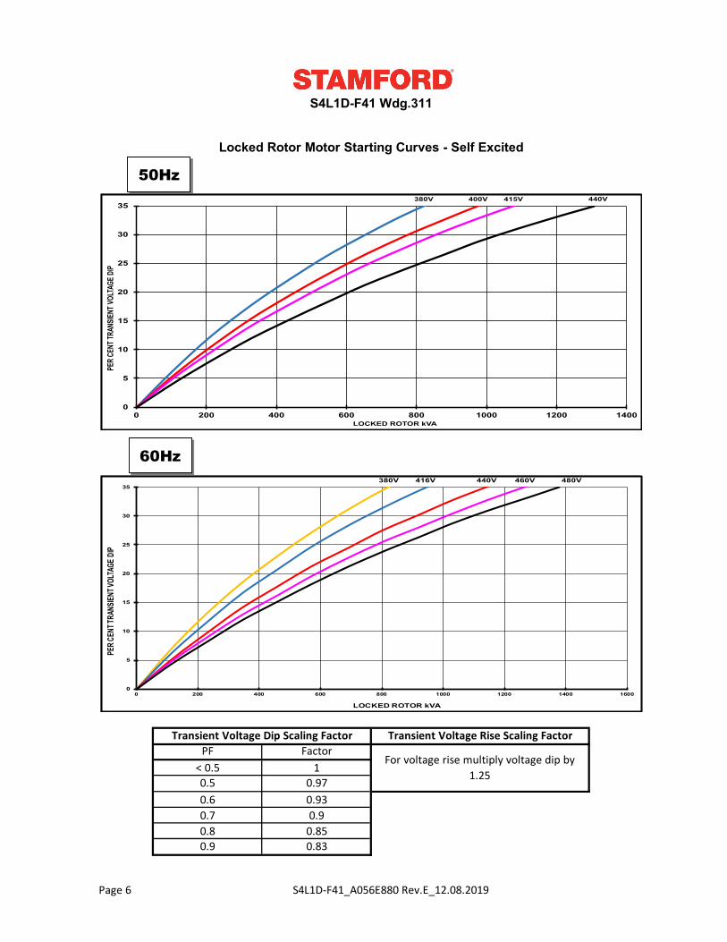
Locked Rotor Motor Starting Curves - Self Excited
Transient Voltage Dip Scaling Factor Transient Voltage Rise Scaling FactorPF Factor
For voltage rise multiply voltage dip by 1.25
< 0.5 10.5 0.97
0.9 0.83
0.6 0.930.7 0.90.8 0.85
50Hz
60Hz
insert curve
insert curve
380V 400V 415V 440V
0
5
10
15
20
25
30
35
0 200 400 600 800 1000 1200 1400
PER C
ENT T
RANS
IENT V
OLTA
GE D
IP
LOCKED ROTOR kVA
380V 416V 440V 460V 480V
0
5
10
15
20
25
30
35
0 200 400 600 800 1000 1200 1400 1600
PER C
ENT T
RANS
IENT V
OLTA
GE D
IP
LOCKED ROTOR kVA
Page 6 S4L1D-F41_A056E880 Rev.E_12.08.2019
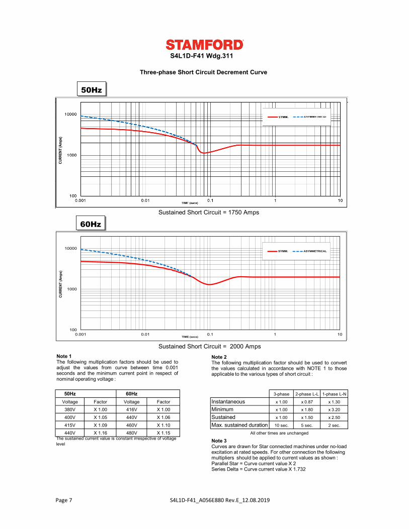
50Hz 60Hz 3-phase 2-phase L-L 1-phase L-N
Voltage Factor Voltage Factor Instantaneous x 1.00 x 0.87 x 1.30
380V X 1.00 416V X 1.00 Minimum x 1.00 x 1.80 x 3.20
400V X 1.05 440V X 1.06 Sustained x 1.00 x 1.50 x 2.50
415V X 1.09 460V X 1.10 10 sec. 5 sec. 2 sec.
440V X 1.16 480V X 1.15
S4L1D-F41 Wdg.311
The sustained current value is constant irrespective of voltage level
All other times are unchanged
Three-phase Short Circuit Decrement Curve
Max. sustained duration
Sustained Short Circuit = 1750 Amps
Sustained Short Circuit = 2000 Amps
60Hz
Note 1The following multiplication factors should be used toadjust the values from curve between time 0.001seconds and the minimum current point in respect ofnominal operating voltage :
Note 2The following multiplication factor should be used to convertthe values calculated in accordance with NOTE 1 to thoseapplicable to the various types of short circuit :
Note 3Curves are drawn for Star connected machines under no-load excitation at rated speeds. For other connection the following multipliers should be applied to current values as shown : Parallel Star = Curve current value X 2Series Delta = Curve current value X 1.732
50Hzinsert curve
insert curve
100
1000
10000
0.001 0.01 0.1 1 10
CURR
ENT
(Am
ps)
TIME (secs)
SYMM. ASYMMETRICAL
Page 7 S4L1D-F41_A056E880 Rev.E_12.08.2019
S4L1D-F41 Wdg.311
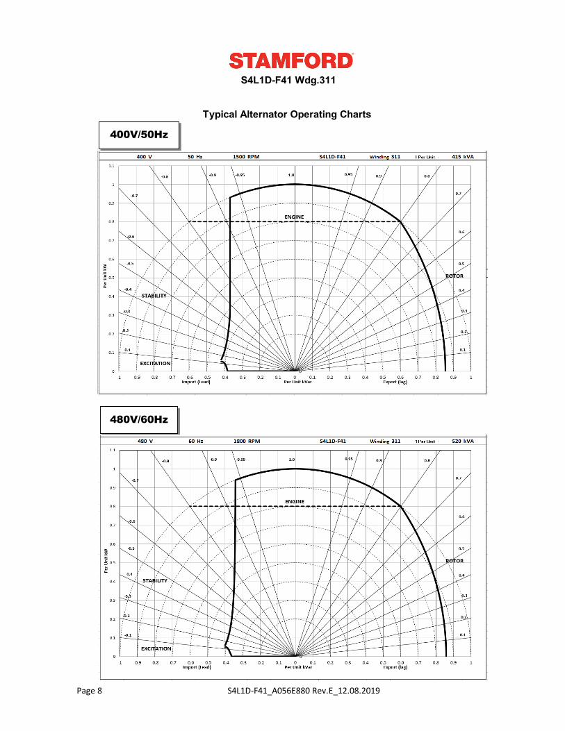
Typical Alternator Operating Charts
400V/50Hz
480V/60Hz
Inser chart
Inser chart
Page 8 S4L1D-F41_A056E880 Rev.E_12.08.2019
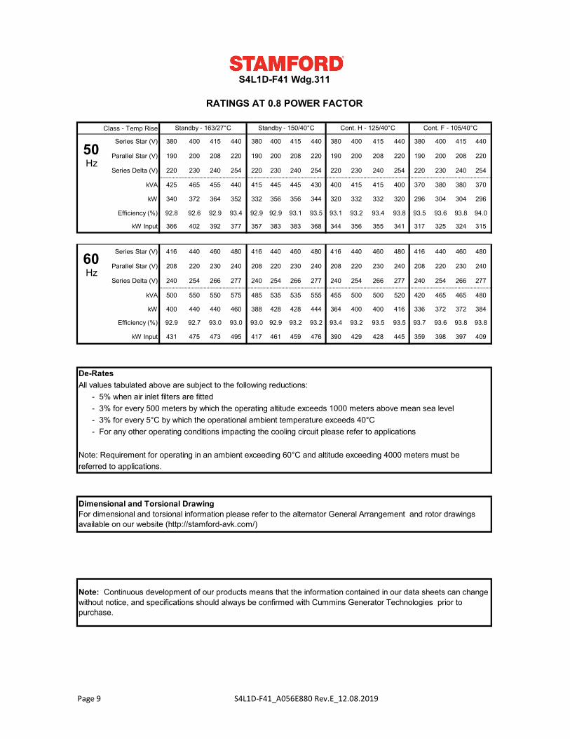
Class - Temp Rise
Series Star (V) 380 400 415 440 380 400 415 440 380 400 415 440 380 400 415 440
Parallel Star (V) 190 200 208 220 190 200 208 220 190 200 208 220 190 200 208 220
Series Delta (V) 220 230 240 254 220 230 240 254 220 230 240 254 220 230 240 254
kVA 425 465 455 440 415 445 445 430 400 415 415 400 370 380 380 370
kW 340 372 364 352 332 356 356 344 320 332 332 320 296 304 304 296
Efficiency (%) 92.8 92.6 92.9 93.4 92.9 92.9 93.1 93.5 93.1 93.2 93.4 93.8 93.5 93.6 93.8 94.0
kW Input 366 402 392 377 357 383 383 368 344 356 355 341 317 325 324 315
Series Star (V) 416 440 460 480 416 440 460 480 416 440 460 480 416 440 460 480
Parallel Star (V) 208 220 230 240 208 220 230 240 208 220 230 240 208 220 230 240
Series Delta (V) 240 254 266 277 240 254 266 277 240 254 266 277 240 254 266 277
kVA 500 550 550 575 485 535 535 555 455 500 500 520 420 465 465 480
kW 400 440 440 460 388 428 428 444 364 400 400 416 336 372 372 384
Efficiency (%) 92.9 92.7 93.0 93.0 93.0 92.9 93.2 93.2 93.4 93.2 93.5 93.5 93.7 93.6 93.8 93.8
kW Input 431 475 473 495 417 461 459 476 390 429 428 445 359 398 397 409
De-RatesAll values tabulated above are subject to the following reductions: - 5% when air inlet filters are fitted - 3% for every 500 meters by which the operating altitude exceeds 1000 meters above mean sea level - 3% for every 5°C by which the operational ambient temperature exceeds 40°C - For any other operating conditions impacting the cooling circuit please refer to applications
Note: Requirement for operating in an ambient exceeding 60°C and altitude exceeding 4000 meters must bereferred to applications.
S4L1D-F41 Wdg.311
Cont. F - 105/40°CCont. H - 125/40°CStandby - 150/40°CStandby - 163/27°C
Dimensional and Torsional DrawingFor dimensional and torsional information please refer to the alternator General Arrangement and rotor drawings available on our website (http://stamford-avk.com/)
Note: Continuous development of our products means that the information contained in our data sheets can change without notice, and specifications should always be confirmed with Cummins Generator Technologies prior to purchase.
RATINGS AT 0.8 POWER FACTOR
50Hz
60Hz
Page 9 S4L1D-F41_A056E880 Rev.E_12.08.2019
Follow us @stamfordavk
Cummins Generator Technologies
View our videos at youtube.com/stamfordavk
news.stamford-avk.com
For Applications Support:[email protected]
For Customer Service:[email protected]
For General Enquiries:[email protected]
Copyright 2016. Cummins Generator Technologies Ltd. All rights reserved.
Cummins and the Cummins logo are registered trade marks of Cummins Inc.
STAMFORD is a registered trade mark of Cummins Generator Technologies Ltd.