Embed Size (px)
Citation preview
Specifications Category: GAS Specification: S-G-03 (rev. 1) Page: 1 of 150
Document(s): See references Issue Date: 2016-XX-XX Effective Date: 2016-XX-XX
Supersedes: LMB-EG-08 and S-G-03
Draft specifications for the approval of type of gas meters, ancillary devices
and associated measuring instruments
Category: GAS Specification: S-G-03 (rev. 1) Page: 2 of 150
Document(s): See references Issue Date: 2016-XX-XX Effective Date: 2016-XX-XX
Supersedes: LMB-EG-08 and S-G-03
Table of contents Part 1: General 3
Part 2: Diaphragm meters 35
Part 3: Rotary meters 40
Part 4: Turbine meters 44
Part 5: Orifice meters 51
Part 6: Mass flow meters 56
Part 7: Ultrasonic meters 61
Part 8: Fluidic oscillation gas meters 62
Part 9: Cone-shaped differential pressure meters 66
Part 10: Mechanical volume conversion devices 70
Part 11: Electronic volume conversion devices/functions and flow computers 79
Part 12: Electrical pulse devices/functions 90
Part 13: Indicating devices 94
Part 14: Gas chromatographs 101
Part 15: Dispensers for natural gas 105
Part 16: Pressure regulators 114
Part 17: Temperature and pressure transmitters 117
Part 18: Correction function of gas meters 122
Part 19: Densitometers 126
Part 20: Flow conditioners used in gas measurement systems 131
Part 21: Conditioning orifice plates 136
Appendix A: Overview of specific applicable metrological requirements for different device
applications 140
Appendix B: Overview of applicable requirements and tests for different gas meter applications
141
Appendix C: Algorithms used to evaluate the performance of cone-shaped differential pressure
meters 143
Appendix D: Algorithms used to evaluate the performance of conditioning orifice plate meters
146

Category: GAS Specification: S-G-03 (rev. 1) Page: 3 of 150
Document(s): See References Issue Date: 2016-XX-XX Effective Date: 2016-XX-XX
Supersedes: LMB-EG-08 and S-G-03
Part: 1 Title: General
Part 1: General
Table of contents
Purpose ..............................................................................................................................5 1.0 Scope ..................................................................................................................................5 2.0 Authority .............................................................................................................................5 3.0 References .........................................................................................................................5 4.0 Terminology .......................................................................................................................7 5.0 Units ................................................................................................................................. 14 6.0
6.1 Use of units ....................................................................................................................... 14 6.2 Metric units of measure .................................................................................................... 14 6.3 Electronic display of units of measure for non-trade purposes ........................................ 15 Metrological requirements ............................................................................................. 15 7.0
7.1 Rated operating conditions ............................................................................................... 15 7.2 Gas meter flow rate characteristics .................................................................................. 16 7.3 Maximum permissible errors ............................................................................................ 16 7.4 Weighted mean error ........................................................................................................ 17 7.5 Repeatability ..................................................................................................................... 17 7.6 Working pressure.............................................................................................................. 17 7.7 Temperature ..................................................................................................................... 17 7.8 Durability ........................................................................................................................... 17 7.9 Vibrations and shocks ...................................................................................................... 17 7.10 Orientation ........................................................................................................................ 17 7.11 Flow direction .................................................................................................................... 18 7.12 Flow disturbance............................................................................................................... 18 7.13 Drive shaft (torque) ........................................................................................................... 18 7.14 Different gases.................................................................................................................. 18 7.15 Influences from ancillary devices ...................................................................................... 18 7.16 Supply voltage variation ................................................................................................... 18 7.17 Uncertainty ........................................................................................................................ 19 Technical requirements ................................................................................................. 19 8.0
8.1 Design, composition and construction .............................................................................. 19

Category: GAS Specification: S-G-03 (rev. 1) Page: 4 of 150
Document(s): See References Issue Date: 2016-XX-XX Effective Date: 2016-XX-XX
Supersedes: LMB-EG-08 and S-G-03
Part: 1 Title: General
8.2 Case ................................................................................................................................. 19 8.3 Zero flow ........................................................................................................................... 20 8.4 Flow direction .................................................................................................................... 20 8.5 Indicating device provisions .............................................................................................. 20 8.6 Output ............................................................................................................................... 20 8.7 Power sources .................................................................................................................. 21 8.8 Software ............................................................................................................................ 21 Marking requirements .................................................................................................... 21 9.0
9.1 General ............................................................................................................................. 21 9.2 Temperature converted volume ........................................................................................ 22 9.3 Pressure converted volume .............................................................................................. 23 9.4 Unidirectional gas flow ...................................................................................................... 23 9.5 Bi-directional gas flow ....................................................................................................... 23 9.6 Output shaft ...................................................................................................................... 23 9.7 Electronic devices ............................................................................................................. 23 9.8 Contractor ......................................................................................................................... 24 9.9 Ancillary devices ............................................................................................................... 24
Sealing requirements ..................................................................................................... 24 10.0 Administrative requirements ......................................................................................... 25 11.0
11.1 Application for approval .................................................................................................... 25 11.2 Approval evaluation .......................................................................................................... 25 11.3 Samples ............................................................................................................................ 26 11.4 Provisions for Measurement Canada testing ................................................................... 27 11.5 Provisions for third party test data from a recognized test facility .................................... 27
Performance tests .......................................................................................................... 27 12.012.1 General ............................................................................................................................. 27 12.2 Test conditions.................................................................................................................. 28 12.3 Flow rate test points ......................................................................................................... 30 12.4 Test gases ........................................................................................................................ 30 12.5 Evaluation tests ................................................................................................................ 30

Category: GAS Specification: S-G-03 (rev. 1) Page: 5 of 150
Document(s): See References Issue Date: 2016-XX-XX Effective Date: 2016-XX-XX
Supersedes: LMB-EG-08 and S-G-03
Part: 1 Title: General
Purpose 1.0
1.1 The purpose of these specifications is to establish the design, composition, construction, performance and sealing/security requirements for the approval of gas meters, ancillary devices and associated measuring instruments based on any measurement technology or principle that is used to measure the quantity or properties of gas at operating conditions. 1.2 This document addresses metrological, technical, marking, sealing, administrative and performance test requirements associated with an approved gas meter or ancillary device or associated measuring instrument intended to measure quantities or properties of gaseous fuels or other gases. 1.3 All metering features or functions of devices that are not explicitly addressed in these specifications are also subject to any additional Measurement Canada (MC) requirement and specification that is applicable based on the technology, principle, feature or function. 1.4 These specifications address general requirements in Part 1 and additional requirements applicable to various types of devices are set forth in subsequent parts specific thereto. 1.5 This document also provides the conditions and the minimum tests1 an applicant shall conduct and submit results for with the application for approval, as prescribed in Part III, paragraph 13(c) of the Electricity and Gas Inspection Regulations.
Scope 2.0 2.1 These specifications apply to gas meters, ancillary devices and associated measuring instruments approved by MC pursuant to the requirements of the Electricity and Gas Inspection Act and Regulations. 2.2 Integral correction devices and devices for internal temperature compensation are included in the scope of these specifications as well as any other electronic devices that may be attached to the gas meter. 2.3 These specifications shall not be applied to meters used with gases in the liquefied state and steam.
Authority 3.0 These specifications are issued under the authority of section 9 of the Electricity and Gas Inspection Act and Part III of the Electricity and Gas Inspection Regulations established thereto.
References2 4.0 4.1 American Gas Association (AGA) NX-19: Manual for the determination of supercompressibility factors for natural gas (1963)
Category: GAS Specification: S-G-03 (rev. 1) Page: 6 of 150
Document(s): See References Issue Date: 2016-XX-XX Effective Date: 2016-XX-XX
Supersedes: LMB-EG-08 and S-G-03
Part: 1 Title: General
4.2 AGA Report No.3: Orifice Metering of Natural Gas and Other Related Hydrocarbon Fluids – Concentric, Square-edged Orifice Meters, Part 1: General Equations and Uncertainty Guidelines – American Petroleum Institute Manual of Petroleum Measurement Standards, chapter 14.3.1 (Fourth edition, September 2012) 4.3 AGA Report No.3: Orifice Metering of Natural Gas and Other Related Hydrocarbon Fluids, Part 2: Specification and Installation Requirements (Fourth edition, 2000) 4.4 AGA Report No.3: Orifice Metering of Natural Gas and Other Related Hydrocarbon Fluids – Concentric, Square-edged Orifice Meters, Part 3: Natural Gas Applications – American Petroleum Institute Manual of Petroleum Measurement Standards, chapter 14.3.3 (Fourth edition, 2013) 4.5 AGA Report No.3: Orifice Metering of Natural Gas and Other Related Hydrocarbon Fluids, Part 4: Background, Development, Implementation Procedure, and Subroutine Documentation for Empirical Flange – Tapped Discharge Coefficient Equation (1992) 4.6 AGA Report No.7: Measurement of Natural Gas by Turbine Meters (February 2006) 4.7 AGA Report No.8: Compressibility and Supercompressibility for Natural Gas and Other Hydrocarbon Gases – American Petroleum Institute MPMS Chapter 14.2 (Second Edition, 1994) 4.8 AGA Report No.11: Measurement of Natural Gas by Coriolis Meter – American Petroleum Institute MPMS, Chapter 14.9 (Second edition, 2013) 4.9 Canada Standards Association (CSA) B149.1-10: Natural gas and propane installation code (latest version) 4.10 CSA Metric Practice Guide Z234.1 4.11 Electricity and Gas Inspection Act (R.S.C., 1985, c. E-4) 4.12 Electricity and Gas Inspection Regulations (SOR/86-131) 4.13 Evaluation of Measurement Data — Guide to the Expression of Uncertainty in Measurement (GUM), JCGM 100:2008 (GUM 1995 with minor corrections) 4.14 Gas Processors Association (GPA) 2145 Standard: Table of Physical Properties for Hydrocarbons and Other Compounds of Interest to the Natural Gas Industry (2009) 4.15 GPA 2172 Standard: Calculation of Gross Heating Value, Relative Density, Compressibility and Theoretical Hydrocarbon Liquid Content for Natural Gas Mixtures for Custody Transfer (Third edition, 2009) 4.16 International Vocabulary of Metrology — Basic and General Concepts and Associated Terms (VIM) (Third edition, 2008 with minor corrections)

Category: GAS Specification: S-G-03 (rev. 1) Page: 7 of 150
Document(s): See References Issue Date: 2016-XX-XX Effective Date: 2016-XX-XX
Supersedes: LMB-EG-08 and S-G-03
Part: 1 Title: General
4.17 OIML R 137-1 & 2: International Organization of Legal Metrology, International Recommendation, Gas meters — Part 1: Metrological and technical requirements — Part 2: Metrological controls and performance tests (2012) 4.18 OIML R 140: International Organization of Legal Metrology, International Recommendation, Measuring systems for gaseous fuel (2007) 4.19 OIML D11: General Requirements for Measuring Instruments — Environmental Conditions (2013) 4.20 OIML V1: International Vocabulary of Terms in Legal Metrology (VIML) (2013) 4.21 S-EG-02: Specifications for Approval of Physical Sealing Provisions for Electricity and Gas Meters (latest version) 4.22 S-EG-05: Specifications for the Approval of Software Controlled Electricity and Gas Metering Devices (latest version) 4.23 S-EG-06: Specifications Relating to Event Loggers for Electricity and Gas Metering Devices (latest version)
Terminology 5.0 Ancillary (auxiliary) device (OIML R137-1, 3.1.8) (dispositif complémentaire (appareil auxiliaire)) Device intended to perform a particular function, directly involved in elaborating, transmitting or displaying measurement results. An ancillary device is not necessarily subject to metrological control and may be integrated in the gas meter. Associated measuring instrument (OIML V1, 5.09) (instrument de mesure associé) Instrument for the measurement of a quantity, other than the measurand, the value of which is used to correct or convert a measurement result. Typically, an associated measuring instrument is connected to a device (correction device, conversion device, calculator3) that is part of a measuring instrument and that changes (corrects, converts) the measurement result to obtain a value for the measurand under specified conditions. Attestation of compliance (attestation de conformité) Attestation originating from an authorized signing authority who has been appropriately designated by the device manufacturing corporation to represent it for these purposes as part of the pattern approval process. Base conditions (OIML R137-1, 3.2.19) (conditions de base) Conditions to which the measured volume of gas is converted (examples: base temperature and base pressure).
Category: GAS Specification: S-G-03 (rev. 1) Page: 8 of 150
Document(s): See References Issue Date: 2016-XX-XX Effective Date: 2016-XX-XX
Supersedes: LMB-EG-08 and S-G-03
Part: 1 Title: General
Contractor's badge (plaque du fournisseur) Nameplate, tag, sticker, electronic display or other suitable means permanently affixed to a device in a conspicuous location. The badge may be used to display or provide access to the device's inspection number assigned by the contractor and other information relative to the current mode of operation of the device to which the badge is attached. Correction (VIM 2.53) Compensation for an estimated systematic effect. The compensation can take different forms, such as an addend or a factor, or can be deduced from a table. Correction device (OIML R137-1, 3.1.7) (dispositif de correction) Device intended for correction of known errors as a function of e.g. flow rate, Reynolds number (curve linearization), or density, pressure and/or temperature. Conversion Conversion of the measurement at operating conditions into measurement at base or standard conditions by taking into account the gas characteristics (i.e. pressure, temperature, composition, density). Conversion device (dispositif de conversion) Integral or non-integral device or function which automatically converts the volume or mass measured at operating conditions into a volume at base or standard conditions by taking into account the flowing gas conditions and characteristics. Cyclic volume (OIML R137-1, 3.2.3) (volume cyclique) Volume of gas corresponding to one full revolution of the moving part(s) inside the meter (working cycle).4 Device (appareil) A gas meter, ancillary device or associated measuring instrument used for the purpose of making measurements of, or obtaining the basis of a charge for, gas supplied to a purchaser. The term device is equivalent to the term meter in the Electricity and Gas Inspection Act and Electricity and Gas Inspection Regulations. Durability (OIML R137-1, 3.2.10) (durabilité) Ability of a measuring instrument to maintain its performance characteristics over a period of use. Electronic display (affichage électronique) Device or other means used to visually present the value of a measured quantity and other relevant information. It may take the form of an integral part of a device (e.g. gas meter) or a separate display module.

Category: GAS Specification: S-G-03 (rev. 1) Page: 9 of 150
Document(s): See References Issue Date: 2016-XX-XX Effective Date: 2016-XX-XX
Supersedes: LMB-EG-08 and S-G-03
Part: 1 Title: General
Electronic register (registre électronique) Memory location integral or non-integral to the device where the value of a measured quantity is electronically recorded. Fault (OIML R137-1, 3.2.7) (défaut) Difference between the error of indication and the error determined under reference conditions of a meter. Flow computer (débitmètre-ordinateur) Device that receives and transforms the output signals from one or more flow measuring devices or from another flow computer and possibly from the associated measuring instruments, and, if appropriate, stores data in memory until they are used. In addition, the flow computer may be capable of transmitting and receiving data from peripheral equipment. Flow rate, Q (OIML R137-1, 3.3.1) (débit) Quotient of the actual quantity of gas passing through the gas meter and the time taken for this quantity to pass through the gas meter. Flow algorithm (algorithme d’écoulement) Mathematical relationship used to transform the measured pressure differential in the device to a mass flow or volumetric flow rate at operating conditions. Gas meter (OIML R137-1, 3.1.1) (compteur de gaz) Instrument intended to measure, memorize and display the quantity of gas passing the flow sensor. Host meter (compteur hôte) Gas meter to which ancillary measurement devices or indicators have been attached. Indicating device (OIML V1, 5.04) (dispositif indicateur) Part of the measuring instrument which displays the measurement results either continuously or on demand. Influence quantity (VIM 2.52) (grandeur d’influence) Quantity that, in a direct measurement, does not affect the quantity that is actually measured, but affects the relation between the indication and the measurement result.

Category: GAS Specification: S-G-03 (rev. 1) Page: 10 of 150
Document(s): See References Issue Date: 2016-XX-XX Effective Date: 2016-XX-XX
Supersedes: LMB-EG-08 and S-G-03
Part: 1 Title: General
Integral element (élément intégré) Being part of a particular approved device (e.g. integral volume conversion function, integral pulse initiator, integral indicating device). Intrinsic error (OIML D 11, 3.7) (erreur intrinsèque) Error determined under reference conditions. Linearity (linéarité) Maximum difference between the weighted mean error and any of the individual errors for test points between Qmin and Qmax. Maximum flow rate, Qmax (OIML R137-1, 3.3.2) (débit maximal) Highest flow rate at which a gas meter is required to operate within the limits of its maximum permissible error, whilst operated within its rated operating conditions. Maximum peak-to-peak error (erreur maximale crête à crête) Difference between the largest and the smallest errors throughout the calibrated range of the meter. Maximum permissible error (VIM 4.26) (erreur maximale tolérée) The maximum permissible error is the extreme value of measurement error, with respect to a known reference quantity value, permitted by specifications or regulations for a given measurement, measuring instrument, or measuring system. Maximum permissible meter / meter tube step change (variation d’échelon maximale premise du compteur ou de sa conduit) Largest allowable diameter ratio between the inside diameter of the meter tube (upstream and downstream section) and the inside diameter of the meter. It is provided by the meter manufacturer. Maximum permissible meter non-axial alignment (écart d’alignement non-axial maximal permis du compteur) Largest allowable angle of the meter alignment with the pipe centerline. It is provided by the meter manufacturer. Small variations in cone alignments have a significant effect on the performance of cone-shaped differential pressure meters. Maximum working pressure, Pmax (OIML R137-1, 3.3.9) (pression de travail maximale) Maximum internal pressure that a gas meter can withstand, within its rated operating conditions, without deterioration of its metrological performance.
Category: GAS Specification: S-G-03 (rev. 1) Page: 11 of 150
Document(s): See References Issue Date: 2016-XX-XX Effective Date: 2016-XX-XX
Supersedes: LMB-EG-08 and S-G-03
Part: 1 Title: General
Measurand (OIML R137-1, 3.1.2) (mesurande) Quantity intended to be measured. Measuring transducer (VIM 3.7) (transducteur de mesure) Device, used in measurement, that provides an output quantity having a specified relation to the input quantity. Examples: Thermocouple, electric current transformer, strain gauge, pH electrode, Bourdon tube, bimetallic strip. Mechanical indicating device (dispositif indicateur mécanique) Pointer-type or drum-type mechanical device that is integral or non-integral to the gas meter, where the value of a measured quantity is recorded and visually presented. Minimum flow rate, Qmin (OIML R137-1, 3.3.3) (débit minimal) Lowest flow rate at which a gas meter is required to operate within the limits of its maximum permissible error, whilst operated within its rated operating conditions. Minimum measured quantity (quantité minimale mesurée) Smallest quantity for which the measurement is metrologically acceptable for a device. It is declared/attested by the manufacturer. Minimum working pressure, Pmin (OIML R137-1, 3.3.9) (pression de travail minimale) Minimum internal pressure that a gas meter can withstand, within its rated operating conditions, without deterioration of its metrological performance. Module (module) Self-contained component of a device that has a well-defined interface to the other components of the device. It often has its own Notice of Approval and is interchangeable. Non-integral element (élément externe) Used with but not part of a particular approved device and separately approved (e.g. non-integral pressure/temperature transducers/transmitters, non-integral pulse generators). Non-volatile memory (mémoire rémanente) Memory that retains data even if the power supply is turned off. Notice of approval (avis d’approbation) Legal confirmation that a measuring device meets applicable regulatory requirements and can be used for trade measurement in Canada.

Category: GAS Specification: S-G-03 (rev. 1) Page: 12 of 150
Document(s): See References Issue Date: 2016-XX-XX Effective Date: 2016-XX-XX
Supersedes: LMB-EG-08 and S-G-03
Part: 1 Title: General
Operating conditions (OIML R137-1, 3.12.16) (conditions de fonctionnement) Conditions of the gas (temperature, pressure and gas composition) at which the quantity of gas is measured. Quantity of gas (OIML R137-1, 3.2.1) (quantité de gaz) Total quantity of gas obtained by integrating the flow passed through the gas meter over time, which is expressed as volume V or mass m, disregarding the time taken. Rated capacity (capacité nominale) Qmax determined by the manufacturer. Rated operating conditions (OIML R137-1, 3.2.17) (conditions assignées de fonctionnement) Conditions of use giving the range of values of the measurand and the influence quantities, for which the errors of the gas meter are required to be within the limits of the maximum permissible error. Reference conditions (OIML R137-1, 3.2.18) (conditions de référence) Set of reference values, or reference ranges of influence quantities, prescribed for testing the performance of a gas meter, or for the intercomparison of the results of measurements. Registration (enregistrement) Visual indication and recorded representation of quantity. Relative error (erreur relative) Absolute error of measurement divided by the conventional true value of the measurand, and traditionally referred to as the true error. Expressed as a percentage, relative error is calculated as follows:
𝐸𝑟 = �𝑄𝑚 − 𝑄𝑠
𝑄𝑠� 𝑥 100% = �
𝑄𝑚
𝑄𝑠− 1� 𝑥 100%
Where, Er is the relative error of the meter under test, expressed in percent (%) Qm is the quantity indicated by the device under test Qs is the quantity indicated by the reference standard, expressed in the same units as Qm Repeatability error (erreur de répétabilité) Difference between the largest and the smallest results of successive measurements of the same quantity carried out under the same conditions.
Category: GAS Specification: S-G-03 (rev. 1) Page: 13 of 150
Document(s): See References Issue Date: 2016-XX-XX Effective Date: 2016-XX-XX
Supersedes: LMB-EG-08 and S-G-03
Part: 1 Title: General
Retrofit (rattrapage) Addition of a component or an accessory to an existing device that was approved and manufactured without it. Reynolds number (nombres de Reynolds) Dimensionless ratio which can be expressed in terms of the volumetric flow rate (Q), the inside pipe diameter (D), the flowing gas density (ρ) and the flowing gas absolute viscosity (µ). Sensor (VIM 3.8) (capteur) Element of a measuring system that is directly affected by a phenomenon, body, or substance carrying a quantity to be measured. Examples: Sensing coil of a platinum resistance thermometer, rotor of a turbine flow meter and Bourdon tube of a pressure gauge. Supercompressibility (surcompressibilité) Within the range of conditions normally encountered in the natural gas industry, the deviation of the actual density and the ideal gas density obtained by the ideal gas law (Charles & Boyles). Calculation of supercompressibility factor is in accordance with AGA Report No.8: Compressibility and Supercompressibility for Natural Gas and Other Hydrocarbon Gases – American Petroleum Institute MPMS Chapter 14.2 (Second Edition, 1994). Telemetering (télémesure) The transmission of measurement information with the aid of intermediate means5 that permits the source meter’s register reading to be duplicated and/or interpreted at a distance. Telemetering device (dispositif de télémesure) Device used in a telemetering system to duplicate the register reading of the source meter. The device may be external or integral to the source meter. Telemetering system (système de télémesure) All devices and equipment used to duplicate and/or interpret a source meter’s register reading(s) at a distance. Test limit (limite d’essai) Limit established when the specification limit is adjusted for the associated measurement uncertainty. Transitional flow rate, Qt (OIML R137-1, 3.3.4) (débit de transition) Flow rate which occurs between the maximum flow rate Qmax and the minimum flow rate Qmin that divides the flow rate range into two zones, the “upper zone” and the “lower zone”, each characterized by its own maximum permissible error.6
Category: GAS Specification: S-G-03 (rev. 1) Page: 14 of 150
Document(s): See References Issue Date: 2016-XX-XX Effective Date: 2016-XX-XX
Supersedes: LMB-EG-08 and S-G-03
Part: 1 Title: General
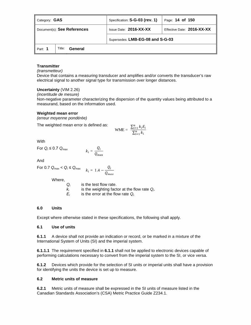
Transmitter (transmetteur) Device that contains a measuring transducer and amplifies and/or converts the transducer’s raw electrical signal to another signal type for transmission over longer distances. Uncertainty (VIM 2.26) (incertitude de mesure) Non-negative parameter characterizing the dispersion of the quantity values being attributed to a measurand, based on the information used. Weighted mean error (erreur moyenne pondérée)
The weighted mean error is defined as:
WME = ∑ 𝑘𝑖𝐸𝑖
𝑛i=1
∑ 𝑘𝑖𝑛i=1
With
For Qi ≤ 0.7 Qmax 𝑘𝑖 =𝑄𝑖
𝑄max
And
For 0.7 Qmax < Qi ≤ Qmax 𝑘𝑖 = 1.4 −𝑄𝑖
𝑄𝑚𝑚𝑚
Where, Qi is the test flow rate. ki is the weighting factor at the flow rate Qi. Ei is the error at the flow rate Qi.
Units 6.0 Except where otherwise stated in these specifications, the following shall apply. 6.1 Use of units 6.1.1 A device shall not provide an indication or record, or be marked in a mixture of the International System of Units (SI) and the imperial system. 6.1.1.1 The requirement specified in 6.1.1 shall not be applied to electronic devices capable of performing calculations necessary to convert from the imperial system to the SI, or vice versa. 6.1.2 Devices which provide for the selection of SI units or imperial units shall have a provision for identifying the units the device is set up to measure. 6.2 Metric units of measure 6.2.1 Metric units of measure shall be expressed in the SI units of measure listed in the Canadian Standards Association’s (CSA) Metric Practice Guide Z234.1.

Category: GAS Specification: S-G-03 (rev. 1) Page: 15 of 150
Document(s): See References Issue Date: 2016-XX-XX Effective Date: 2016-XX-XX
Supersedes: LMB-EG-08 and S-G-03
Part: 1 Title: General
6.2.2 Where a conflict exists between the CSA standard Z234.1 and the Electricity and Gas Inspection Act or the Electricity and Gas Inspection Regulations, the legislative requirements shall apply. 6.3 Electronic display of units of measure for non-trade purposes The display of units of measure for non-trade purposes, such as monitoring, is permitted.
Metrological requirements 7.0 Except where otherwise stated in these specifications, the following requirements shall apply. 7.1 Rated operating conditions
(a) Ambient temperature range
(i) Non-temperature-controlled environment In the case of devices intended for operation in a non-temperature-controlled environment, the ambient temperature range shall be at least -30 °C to 40 °C.
(ii) Temperature-controlled environment
In the case of devices intended for operation in a temperature-controlled environment, the ambient temperature range shall be as specified by the applicant and such restrictions shall be set out in the Notice of Approval (NOA) issued by MC.
(b) Ambient relative humidity
As specified by the applicant and at least up to 93% (non-condensing).
(c) Atmospheric pressure As specified by the applicant and shall cover at least 86 kPa to 106 kPa (absolute).
(d) DC mains voltage As specified by the applicant.
(e) AC mains voltage Unom – 15% to Unom + 10%
(f) AC mains frequency ƒnom – 2% to ƒnom + 2%
Category: GAS Specification: S-G-03 (rev. 1) Page: 16 of 150
Document(s): See References Issue Date: 2016-XX-XX Effective Date: 2016-XX-XX
Supersedes: LMB-EG-08 and S-G-03
Part: 1 Title: General
(g) Operating flow rate range Qmin to Qmax inclusive.
(h) Type of gases As specified by the applicant.
(i) Working pressure range Pmin to Pmax inclusive. 7.2 Gas meter flow rate characteristics 7.2.1 The flow rate characteristics of a gas meter based on measurement technology sensitive to flow rate changes and/or changes in flow profile (e.g. laminar to turbulent) shall be defined by the values of Qmin, Qt and Qmax. 7.2.2 The ratios and relations shall be within the following ranges:
(a) Where Qmax / Qmin is ≥ 50 → Qmax / Qt shall be ≥ 10
(b) Where Qmax / Qmin ≥ 5 and < 50 → Qmax / Qt shall be ≥ 5 7.3 Maximum permissible errors 7.3.1 General 7.3.1.1 A device shall be designed and manufactured such that its errors do not exceed the applicable maximum permissible error (MPE) under rated operating conditions as specified in subsection 7.1. 7.3.1.2 The applicable MPE to various gas meter applications, ancillary devices and associated measuring instruments are set forth in subsequent parts specific thereto. (See Appendix A) 7.3.2 Correction for known errors A gas meter may be equipped with a correction device/function intended to reduce the errors as close as possible to the zero value. Subject to subsection 7.3.2.1, such a correction device shall not be used for the correction of a pre-estimated drift.
Predetermined error relationships 7.3.2.1 Unless permitted by the NOA, a gas meter shall not be equipped with a correction device/function which extrapolates a meter’s performance through characterization of a general meter type at or below Qmin.
Category: GAS Specification: S-G-03 (rev. 1) Page: 17 of 150
Document(s): See References Issue Date: 2016-XX-XX Effective Date: 2016-XX-XX
Supersedes: LMB-EG-08 and S-G-03
Part: 1 Title: General
7.4 Weighted mean error The weighted mean error shall be within ± 0.4%, except where otherwise stated in these specifications. (See Appendix A) 7.5 Repeatability The repeatability of the errors of at least three consecutive measurements at the specific flow rate shall be less than or equal to one-third of the MPE as specified in 7.3.1.2, except where otherwise stated in these specifications. (See Appendix A) 7.6 Working pressure The requirements as specified in subsection 7.3 shall be fulfilled over the whole working pressure range. 7.7 Temperature The requirements as specified in subsection 7.3 shall be fulfilled over the whole temperature range. 7.8 Durability Subject to subsection 12.5.9, the fault of a gas meter for flow rates from Qt up to Qmax shall be less than or equal to half the MPE. 7.9 Vibrations and shocks 7.9.1 A gas flow meter shall withstand vibrations and shocks with the following specifications:
(a) Vibrations:
(i) Total frequency range: 10 Hz – 150 Hz
(ii) Total root mean square (RMS) level: 7 m∙s-2
(iii) Acceleration spectral density (ASD) level 10 Hz – 20 Hz: 1 m2s-3
(iv) ASD level 20 Hz – 150 Hz: -3 dB/octave
(b) Shocks: height of fall: 50 mm 7.9.2 The fault after the application of vibrations and shocks shall be less than or equal to half the MPE over the whole flow rate range. 7.10 Orientation 7.10.1 Subject to 7.10.2, the device shall fulfill the metrological requirements specified in subsections 7.3 and 7.4 for all orientations.
Category: GAS Specification: S-G-03 (rev. 1) Page: 18 of 150
Document(s): See References Issue Date: 2016-XX-XX Effective Date: 2016-XX-XX
Supersedes: LMB-EG-08 and S-G-03
Part: 1 Title: General
7.10.2 Where the device operates correctly while installed in certain orientations recommended by the manufacturer and for which approval is sought, the metrological requirements mentioned in subsections 7.3 and 7.4 shall be fulfilled for these orientations only. 7.11 Flow direction If the gas meter is marked as being able to measure the flow in both directions, the requirements mentioned in subsections 7.3 and 7.4 shall be fulfilled for each direction separately. 7.12 Flow disturbance 7.12.1 Subject to 7.12.2, for types of gas meters whose accuracy is affected by flow disturbances, the shift of the error due to these disturbances shall not exceed one-third of the MPE. 7.12.2 Where a gas meter is specified to be installed in a specific piping configuration producing only mild flow disturbances, such restrictions shall be set out in the NOA issued by MC and the gas meter shall only be installed in the specific piping configurations in which its accuracy has proven to stay within the requirement. 7.13 Drive shaft (torque) For types of gas meters provided with one or more drive shafts, the manufacturer shall provide the maximum torque that can be applied without exceeding one-third of the MPE. 7.14 Different gases The types of gas meters which are intended to be used for different gases shall comply with the requirements specified in subsection 7.3 over the whole range of gases for which they are specified by the manufacturer. 7.15 Influences from ancillary devices Gas meters provided with ancillary devices shall be designed such that none of the functions of the ancillary devices (e.g. provisions for communication purposes) affect the metrological behaviour. 7.16 Supply voltage variation When a supply voltage variation occurs, the error of the device requiring a power supply from the mains shall not:
(a) exceed the MPE;
(b) deviate by more than ±0.2% from the errors at nominal supply voltage.

Category: GAS Specification: S-G-03 (rev. 1) Page: 19 of 150
Document(s): See References Issue Date: 2016-XX-XX Effective Date: 2016-XX-XX
Supersedes: LMB-EG-08 and S-G-03
Part: 1 Title: General
7.17 Uncertainty 7.17.1 The estimation of the expanded uncertainty U shall be made in accordance with the Guide to the expression of uncertainty in measurement (GUM) with a level of confidence of approximately 95%. 7.17.2 Subject to 7.17.3, the expanded uncertainty U of determination of errors of the measured gas quantity shall be less than one-fifth of the applicable MPE, as specified in subsection 7.3, where applicable. 7.17.3 Where the expanded uncertainty U of errors exceeds one-fifth of the applied MPE, the test results shall be approved by reducing the applied MPE with the excess of the uncertainties.
New MPE = ± �65� × MPE − 1.645u�
Technical requirements 8.0 Except where otherwise stated in these specifications, the following requirements shall apply according to the device technology, principle, feature or function. 8.1 Design, composition and construction 8.1.1 The design shall be suitable for the intended purpose and expected service conditions. 8.1.2 The construction shall be mechanically and electrically sound, and the materials (e.g. finish) shall be such as to provide assurance of long life and sustained accuracy. 8.1.3 Provisions incorporated in gas meters for sensing flowing gas temperature and the performance of temperature conversion and/or supercompressibility correction shall meet the applicable performance requirements over a minimum temperature range of 40 °C. 8.1.4 Subject to 8.1.4.1, in all situations in which the automatic conversion of metered volume takes place, the registration of the unconverted and the converted volume shall be provided at least by the device with integral volume conversion functions or by the non-integral volume conversion device. 8.1.4.1 Where the device is not able to provide the registration of the unconverted and the converted volume, the NOA shall specify that the device shall be used in conjunction with an associated device which can provide the specified information. 8.2 Case 8.2.1 The case of a device intended to contain gas shall be so designed and constructed to effectively maintain its accuracy over the entire ranges of its operating parameters. 8.2.2 The case of a device shall be designed and constructed to withstand environmental conditions and prevent any exterior foreign substance from entering the device.
Category: GAS Specification: S-G-03 (rev. 1) Page: 20 of 150
Document(s): See References Issue Date: 2016-XX-XX Effective Date: 2016-XX-XX
Supersedes: LMB-EG-08 and S-G-03
Part: 1 Title: General
8.3 Zero flow The gas meter totalization shall not change when the flow rate is zero and the installation conditions are free from flow pulsations.7 8.4 Flow direction 8.4.1 Measurement of bi-directional flow 8.4.1.1 Where gas meters are designed for bi-directional gas flow, the quantity of gas passed during reverse flow shall either be subtracted from the registration or recorded separately. 8.4.1.2 The MPE as specified in subsection 7.3 shall be met for both forward and reverse flow. 8.4.2 Reverse flow Gas meters designed for unidirectional measurement shall either prevent reverse flow, or shall withstand incidental or accidental reverse flow without deterioration or change in their metrological properties concerning forward flow measurements. 8.5 Indicating device provisions 8.5.1 Subject to 8.5.2, every device whose function is to provide measurement units shall be equipped with an integral indicating device or provide for connection or attachment of a non-integral indicating device. 8.5.2 Where a device is approved for use with an approved non-integral indicating device, it shall have an approved compatible indicating device connected to it in a manner which allows users to access the measurement unit readings where they are obtained via radio frequency transmitters, the communication port or other form of electronic data communication, subject to the following conditions:
(a) The indicator shall be capable of displaying each legal unit of measure for which the device is approved;
(b) Where an electronic device is used to obtain the units of measure, the
software/firmware used to obtain the measurement readings shall be approved.8 8.6 Output 8.6.1 Subject to 8.6.2, the capacity per device rotating mechanical output shaft (instrument drive or wriggler) shall be such that at Qmax, the output shaft makes at least one rotation every two minutes. 8.6.2 Where the device output is in a form of digital communication, the poling frequency shall be such that the time required verifying the MPE is no more than two minutes.
Category: GAS Specification: S-G-03 (rev. 1) Page: 21 of 150
Document(s): See References Issue Date: 2016-XX-XX Effective Date: 2016-XX-XX
Supersedes: LMB-EG-08 and S-G-03
Part: 1 Title: General
8.7 Power sources 8.7.1 Devices may be powered by three types of power sources that may be used alone or in combination:
(a) Mains power sources
(b) Non-replaceable power sources
The indicated lifetime of the power source shall guarantee that the device functions correctly for at least as long as the operational lifetime of the meter as stated by the manufacturer.
(c) Replaceable power sources9
The replacement of the power source shall not adversely affect the programming,
metering information or subsequent operation of the device. 8.7.2 Electronic devices which calculate measurement units shall be designed such that in the event of a power failure, the measured or calculated quantity of gas as well as any configuration parameters, constants and calibration parameters obtained just before the failure are not lost (i.e. non-volatile memory). 8.8 Software The software requirements applicable to devices within the scope of these specifications are established by the following MC specifications:
(a) S-EG-05: Specifications for the Approval of Software Controlled Electricity and Gas Metering Devices [link 1]
(b) S-EG-06: Specifications Relating to Event Loggers for Electricity and Gas Metering
Devices [link 2]
Marking requirements 9.0 9.1 General 9.1.1 All required markings shall be easily legible and indelible under rated operating conditions and shall not be adversely affected by environmental conditions. 9.1.2 Markings shall not lead to confusion.

Category: GAS Specification: S-G-03 (rev. 1) Page: 22 of 150
Document(s): See References Issue Date: 2016-XX-XX Effective Date: 2016-XX-XX
Supersedes: LMB-EG-08 and S-G-03
Part: 1 Title: General
9.1.3 As relevant, the following information shall be marked on the casing or on a nameplate permanently affixed to the device in such a way as to be easily readable when installed:
(a) Departmental approval number;
(b) Manufacturer's name or registered trademark;
(c) Model or type designation;
(d) Serial number;
(e) Ambient temperature range, where less than -30 °C to 40 °C;
(f) Maximum flow rate Qmax =…<unit>;
(g) Transitional flow rate Qt =…<unit>;10
(h) Minimum flow rate Qmin =…<unit>;
(i) Gas temperature and pressure range for which the errors of the gas meter shall be within the limits of the MPE;11
(j) Maximum allowable operating pressure and where applicable, minimum operating
pressure;
(k) Pulse values of frequency outputs;12
(l) Type and range for analog output signal;13
(m) Protocol/interface for digital output.14 9.1.4 Bar codes or QR (Quick Response) codes shall only be used to supplement or duplicate information that is already marked on the device’s nameplate or displayable on the device’s electronic display as well as an external device (by remote interrogation software). 9.2 Temperature converted volume 9.2.1 Integral temperature converting meters and non-integral temperature converting modules shall have the temperature to which the registered volume is converted (e.g. 15 °C or 60 °F) marked on nameplates. 9.2.2 The information shall be permanently and prominently marked irrespective of background colour.
Category: GAS Specification: S-G-03 (rev. 1) Page: 23 of 150
Document(s): See References Issue Date: 2016-XX-XX Effective Date: 2016-XX-XX
Supersedes: LMB-EG-08 and S-G-03
Part: 1 Title: General
9.3 Pressure converted volume 9.3.1 Integral pressure converting meters and non-integral pressure converting modules shall have the following additional information marked on the nameplate:
(a) Device’s pressure transducer range;
(b) Base pressure;
(c) Where a gauge pressure sensor is used, the atmospheric pressure, or range of atmospheric pressures, for which the device is suitable.
9.4 Unidirectional gas flow Gas meters designed for only unidirectional measurement shall be marked showing the direction of gas flow or shall have the inlet connection identified. 9.5 Bi-directional gas flow 9.5.1 Gas meters designed to measure bi-directional gas flow shall be marked with a double-headed arrow, with a plus (+) and minus (-) sign to indicate which flow direction is positive and which flow direction is negative, respectively. 9.5.2 Electronic devices designed to measure bi-directional gas flow shall provide for and permit access to the identification of the direction of the flowing gas via the device’s electronic display or output to an external device (by remote interrogation software) in a clear and unambiguous manner. 9.6 Output shaft Devices equipped with an external output shaft shall have their direction of rotation visibly marked in the vicinity of the shaft together with the capacity per revolution of the shaft when a device or a cover is attached. 9.7 Electronic devices 9.7.1 Devices requiring an external power supply for operation shall have the following information marked on the nameplate:
(a) The nominal voltage;
(b) The nominal frequency;
(c) The nominal power consumption or input current.
Category: GAS Specification: S-G-03 (rev. 1) Page: 24 of 150
Document(s): See References Issue Date: 2016-XX-XX Effective Date: 2016-XX-XX
Supersedes: LMB-EG-08 and S-G-03
Part: 1 Title: General
9.7.2 Devices powered by a battery or other power sources which must periodically be replaced shall meet the following requirements:
(a) The remaining battery capacity shall be indicated in units of time;15 or
(b) an automatic alarm shall be incorporated that provides an indication when battery life is below 10%.
9.7.3 For a non-replaceable power source, the operational lifetime of the device or, alternatively, the remaining battery capacity in units of time shall be indicated.16 9.7.4 The meter/component firmware and/or software version(s) shall be prominently indicated.17 9.8 Contractor 9.8.1 Space shall be provided for the attachment of a contractor's badge. 9.8.2 Where a device is provided with an adjustment allowing the contractor to change the base pressure or the atmospheric pressure setting or any other operating parameters or its ranges may be set by the contractor, the manufacturer shall provide a nameplate, tag, sticker, electronic read or read/write system (with security) or other suitable means for marking the applicable information. 9.9 Ancillary devices 9.9.1 If an ancillary device is not subject to legal metrology control, this shall be clearly indicated. 9.9.2 Ancillary devices integral to a gas meter shall have a unique identifier (i.e. serial number) marked on the visible face of the device when mounted in the gas meter. 9.9.3 Where the ancillary device equipped with an external input is attached to the output shaft of a device, the following shall be visibly marked in the vicinity of the input shaft:
(a) The direction of rotation;
(b) The capacity per revolution.18
Sealing requirements 10.0 10.1 Subject to 10.3, every device and any interchangeable measuring component thereof shall be constructed so that access to the working parts, adjustments and programming may be effectively prevented by use of the conventional sealing method as per S-EG-02 — Specifications for Approval of Physical Sealing Provisions for Electricity and Gas Meters [link 3]. 10.2 Electrically operated devices shall have sealing provisions designed to accommodate the conventional sealing method, as per S-EG-02 [link 4], to prevent unauthorized access to fuses, circuit breakers, signal connections and the primary and backup electrical source.
Category: GAS Specification: S-G-03 (rev. 1) Page: 25 of 150
Document(s): See References Issue Date: 2016-XX-XX Effective Date: 2016-XX-XX
Supersedes: LMB-EG-08 and S-G-03
Part: 1 Title: General
10.3 Gas meters of modular design which allow interchangeability of modules shall have suitable provision for sealing:
(a) each module separately;
(b) modules together. 10.4 The exposed ends of the drive shaft shall be suitably protected when a gas meter is not connected to an attachable ancillary device. 10.5 Subject to 8.5.1, means provided for the registration of cumulative volume, mass or energy units shall be non-resettable under normal operating conditions once the device is sealed.
Administrative requirements 11.0 11.1 Application for approval 11.1.1 The Application for Type Evaluation Testing — Gas Meters and Auxiliary Devices form [link
5] shall be completed when applying for an NOA under section 9 of the Electricity and Gas Inspection Act . 11.1.1.1 Where applicable, the applicant shall provide MC with the gas meter cyclic volume. 11.1.2 In addition, if software is employed, the following shall be included:
(a) The type approval documentation prescribed by S-EG-05 — Specifications for the Approval of Software Controlled Electricity and Gas Metering Devices [link 6];
(b) A description of how the device equipped with an event logger meets the requirements prescribed by S-EG-06 — Specifications Relating to Event Loggers for Electricity and Gas Metering Devices [link 7].
11.1.3 As an alternative to calibrating using medium pressure natural gas, the applicant shall provide test data demonstrating the pressure / Reynolds number sensitivity of the gas meter. 11.1.3.1 Where test facilities are not available to perform tests over the entire operating pressure range of the gas meter, the applicant shall provide test data demonstrating that the pattern to which the gas meter belongs is either insensitive to operating pressure or may be predicted using a dimensionless number such as the Reynolds number, which will not cause the gas meter’s accuracy to exceed the MPE specified in subsection 7.3. 11.2 Approval evaluation 11.2.1 Gas meters, ancillary devices and associated measuring instruments shall conform to the approved type and the documentation that was submitted in support of approval obtainment.
Category: GAS Specification: S-G-03 (rev. 1) Page: 26 of 150
Document(s): See References Issue Date: 2016-XX-XX Effective Date: 2016-XX-XX
Supersedes: LMB-EG-08 and S-G-03
Part: 1 Title: General
11.2.2 Compliance with the requirements of these specifications shall be established on the basis of a combination of performance testing and written attestations of compliance, where applicable and when accepted by MC. 11.2.2.1 An attestation of compliance shall:
(a) contain the company letterhead;
(b) be addressed to MC;
(c) refer to the approval project and approval number (where applicable);
(d) indicate the section(s) of the specifications that the applicant is attesting to;
(e) explain how the requirements are met. 11.2.3 All attestations of compliance and testing data shall serve as records of compliance and shall be maintained as permanent records in a device's type approval file. 11.2.4 Telemetering devices/functions and ancillary devices incorporated within a gas meter submitted for approval by MC shall be evaluated and approved as integral components of the gas meter and included in its NOA. 11.2.5 Retrofit-type separate ancillary and telemetering devices subject to approval by MC shall be evaluated and approved as separate devices and issued their own NOA. 11.2.6 Retrofit-type telemetering devices submitted for approval shall be evaluated to ensure they do not impair or impact the operation of the approved source gas meter makes/models intended to be retrofitted. 11.2.6.1 Manufacturers of retrofit-type telemetering devices shall demonstrate to MC that the use of their devices is authorized by the manufacturer of the approved source gas meter makes/models intended to be retrofitted. 11.3 Samples Except where otherwise requested by MC, the following rules shall apply:
(a) Where a device comes in various sizes and the design, composition and construction are proportional to its size and the pattern remains the same for the series, two samples representing the smallest and the largest size in the series shall be submitted for evaluation.
(b) Where a device comes in three sequential nominal sizes, the middle nominal sized
device shall be evaluated.
(c) Where a homogeneous series extends to device sizes that exceed the laboratory’s capacity, the next nominal size smaller than the largest size in the series shall be evaluated.

Category: GAS Specification: S-G-03 (rev. 1) Page: 27 of 150
Document(s): See References Issue Date: 2016-XX-XX Effective Date: 2016-XX-XX
Supersedes: LMB-EG-08 and S-G-03
Part: 1 Title: General
11.4 Provisions for Measurement Canada testing When testing is performed by MC, the following shall be supplied or made available by the applicant:
(a) Subject to subsection 11.3, the number of sample devices manufactured in conformity with the type;
(b) Any special equipment required to evaluate the device;
(c) A person with a thorough knowledge of the device;
(d) Other assistance as may be determined throughout the approval process.
11.5 Provisions for third party test data from a recognized test facility 11.5.1 Where the applicant submits test results from a test facility recognized by MC, the test plan shall be approved by MC prior to the testing. 11.5.2 Where test conditions established in these Specifications are not within the scope of recognized test facilities, a proposed method for maintaining the required test conditions during the applicable testing for evaluation shall be submitted to MC and include:
(a) a clear description of the method used to establish and maintain the required test condition(s);
(b) quality assurance and quality control processes used to establish and maintain the
required test condition(s).
Performance tests 12.0 12.1 General 12.1.1 The applicable general and additional specific test requirements based on the technology, principle of measurement, feature or function of the device shall apply when conducting performance tests. (See Appendix B) 12.1.2 Each required test shall meet the requirements as specified in section 7.0, when applicable. 12.1.3 For electronic devices, each required test shall have no effect on the electronic indicator, stored data or the device’s ability to interpret inputs from connected devices. 12.1.4 All influence quantities except for the influence quantity being tested shall remain constant during performance testing of a device.
Category: GAS Specification: S-G-03 (rev. 1) Page: 28 of 150
Document(s): See References Issue Date: 2016-XX-XX Effective Date: 2016-XX-XX
Supersedes: LMB-EG-08 and S-G-03
Part: 1 Title: General
12.2 Test conditions Except where otherwise stated in these specifications, the following requirements shall apply. 12.2.1 “Reference” environmental conditions
(a) Ambient temperature The ambient temperature shall be (20.0 ± 5.0) °C with a rate of change not greater than 0.5 °C per hour.
(b) Atmospheric pressure The atmospheric pressure used in calculations shall be that prevailing at the time of testing.
(c) Relative humidity of ambient air The relative humidity of the ambient air shall be that prevailing at the time of testing.
(d) Density of dry air The density of dry air at standard temperature and standard pressure shall be taken as:
(i) 1.225 kg/m3; or
(ii) 0.07654 lb/ft3.
(e) Power source
Where a device is powered from the mains, the voltage shall be within ± 1.0% of the rated voltage and the frequency shall be within ± 0.2% of the rated voltage.
12.2.2 “Other than reference” environmental conditions
(a) Ambient temperature ranges for devices intended to be used in a non-temperature-controlled environment
(-30.0 ± 2.0) °C and (40.0 ± 2.0) °C.
(b) Ambient temperature range for devices intended to be used in a temperature-controlled environment
As specified by the manufacturer.
Category: GAS Specification: S-G-03 (rev. 1) Page: 29 of 150
Document(s): See References Issue Date: 2016-XX-XX Effective Date: 2016-XX-XX
Supersedes: LMB-EG-08 and S-G-03
Part: 1 Title: General
(c) Moisture
Means shall be employed to prevent the accumulation of moisture in the device during tests conducted at “other than reference” environmental conditions.
(i) Depending on the dew point of the test gas, it may not be feasible to obtain
some of the required temperature values. In these instances, the largest differential temperature obtainable shall be considered.
(ii) The device shall be subjected to the test temperatures for a length of time as is
necessary to establish thermal stability. 12.2.3 Operating conditions
Flowing gas temperature 12.2.3.1
(a) Where a gas is used for testing at “reference” environmental conditions as specified in subsection 12.2.1, its temperature shall be within ± 0.5 °C of the ambient reference temperature, unless temperature corrections are made.
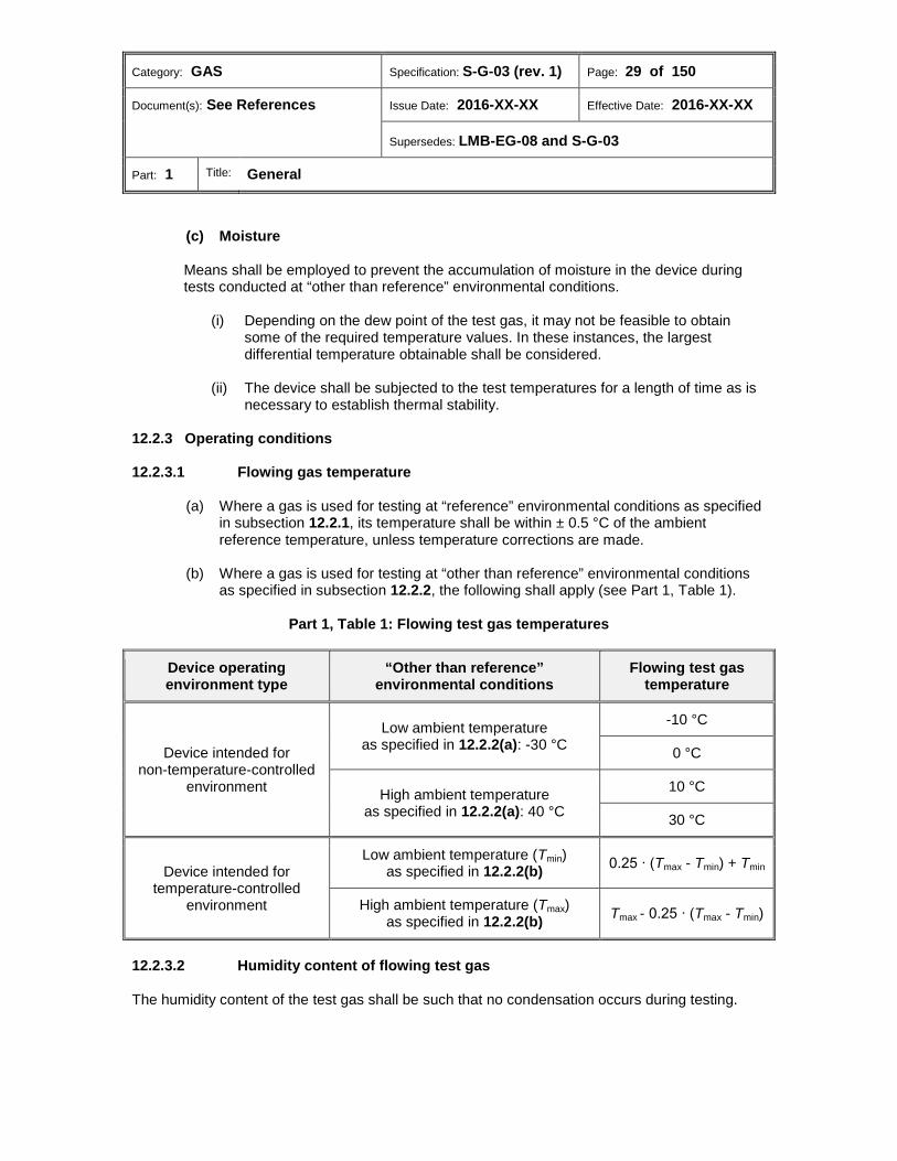
(b) Where a gas is used for testing at “other than reference” environmental conditions
as specified in subsection 12.2.2, the following shall apply (see Part 1, Table 1).
Part 1, Table 1: Flowing test gas temperatures
Device operating environment type
“Other than reference” environmental conditions
Flowing test gas temperature
Device intended for non-temperature-controlled
environment
Low ambient temperature as specified in 12.2.2(a): -30 °C
-10 °C
0 °C
High ambient temperature as specified in 12.2.2(a): 40 °C
10 °C
30 °C
Device intended for temperature-controlled
environment
Low ambient temperature (Tmin) as specified in 12.2.2(b) 0.25 ∙ (Tmax - Tmin) + Tmin
High ambient temperature (Tmax) as specified in 12.2.2(b) Tmax - 0.25 ∙ (Tmax - Tmin)
Humidity content of flowing test gas 12.2.3.2
The humidity content of the test gas shall be such that no condensation occurs during testing.
Category: GAS Specification: S-G-03 (rev. 1) Page: 30 of 150
Document(s): See References Issue Date: 2016-XX-XX Effective Date: 2016-XX-XX
Supersedes: LMB-EG-08 and S-G-03
Part: 1 Title: General
12.3 Flow rate test points 12.3.1 The flow rate at which the errors of the gas meters need to be determined shall be distributed over the measuring range at regular intervals and include Qmin and Qmax (also preferably Qt where applicable). 12.3.2 Based on the number of test points per decade (M), the minimum number (N) of test points, ranking from i = 1 to i = N shall be calculated according to the following equation:
𝑁 = 1 + 𝑀 × log �𝑄max
𝑄min�
Where, N ≥ 6 and rounded to the nearest integer M = 3 unless otherwise specified by MC 12.3.3 For flow rates covering two decades or more, the following equation presents the distribution of flow rates for i = 1 to i = N-1 and QN = Qmin.
𝑄𝑖 = � √10𝑀 �(1−𝑖)
× 𝑄max Where, M = 3 unless otherwise specified by MC 12.3.4 The flow rate shall be within 5% of the value calculated in 12.3.3 except where otherwise stated in these specifications. 12.4 Test gases 12.4.1 Subject to 12.4.2, test mediums19 used for performance testing of the device shall be recognized by MC. 12.4.2 Where test mediums are not recognized by MC, the applicant shall:
(a) contact MC to obtain the requirements for testing and test data submission for the evaluation of the use of the proposed test medium;
(b) have the required testing completed at a test facility recognized by MC and submit
the results to MC for evaluation. 12.5 Evaluation tests 12.5.1 Location of data Devices equipped with an electronic display shall be evaluated to determine if the display’s reading is derived from the same memory location as the output signal used for gating the prover during accuracy testing.
Category: GAS Specification: S-G-03 (rev. 1) Page: 31 of 150
Document(s): See References Issue Date: 2016-XX-XX Effective Date: 2016-XX-XX
Supersedes: LMB-EG-08 and S-G-03
Part: 1 Title: General
12.5.2 Range of programmable parameters 12.5.2.1 Where a device incorporates features which allow the user to set the range or operating parameters of the device, it shall be tested over a range of such features sufficient to establish that the applicable requirements of these specifications are met throughout the range for which approval is sought. 12.5.2.2 All adjustments and recalibrations shall be performed according to the manufacturer's instructions. 12.5.3 Accuracy testing Except where stated otherwise in these specifications, the error of the device shall be determined at test conditions as described in subsection 12.2, while using flow rates according to subsection 12.3. 12.5.4 Repeatability 12.5.4.1 At Qmin, Qt, and Qmax, the errors are determined three times and the difference between the minimum and maximum measured error is calculated.20 12.5.4.2 Each measurement shall be of sufficient duration to provide an error resolution of 0.1% or better. 12.5.5 Orientation 12.5.5.1 Subject to 12.5.5.2, the applicant shall demonstrate that the device is not orientation sensitive; otherwise, devices shall be tested in any orientations recommended by the manufacturer and for which approval is sought. 12.5.5.2 Where no specific mounting orientations are recommended, the accuracy measurements as specified in subsection 12.5.3 shall be performed in the following orientations:
(a) Horizontal;
(b) Vertical flow-up; and
(c) Vertical flow-down. 12.5.5.3 Where the requirements are not fulfilled for all prescribed orientations without intermediate adjustments, the NOA shall set out only the approved orientations. 12.5.6 Flow direction 12.5.6.1 Subject to 12.5.6.2, the accuracy measurements as specified in subsection 12.5.3 for gas meters designed for bi-directional measurement shall be performed without intermediate adjustments in both flow directions.

Category: GAS Specification: S-G-03 (rev. 1) Page: 32 of 150
Document(s): See References Issue Date: 2016-XX-XX Effective Date: 2016-XX-XX
Supersedes: LMB-EG-08 and S-G-03
Part: 1 Title: General
12.5.6.2 Where the requirements are not fulfilled for both flow directions without intermediate adjustments, the bi-directional gas meter shall be considered unidirectional and marked according to subsection 9.4, and such restriction shall be set out in any NOA issued by MC. 12.5.7 Working pressure When practicable, the accuracy measurements as stated in subsection 12.5.3 shall be performed at least at the minimum and maximum operating pressures. 12.5.8 Flow disturbance 12.5.8.1 Subject to 12.5.8.2, where gas meter accuracy is susceptible to installation configuration, the piping configuration shall be the one for which approval is sought that is most likely to cause an error in measurement. 12.5.8.2 Where a piping configuration has been identified, the installation being approved shall conform to the configuration identified or to one of the permissible configurations where more than one has been identified. 12.5.8.3 Where gas meter accuracy is not susceptible to piping configuration, the configuration shall be the manufacturer’s recommended configuration. 12.5.8.4 To evaluate the gas meter’s swirl susceptibility, the following shall apply:
(a) The inlet to the installation configuration recommended by the manufacturer shall be preceded by a clockwise and a counter-clockwise swirl generator constructed of two ninety-degree elbows connected together orthogonally.
(b) The outlet of the upstream disturbance shall be placed a distance of two times the
nominal pipe diameters from the upstream face of the gas meter.
(c) Downstream piping shall be straight and equal in diameter to the upstream piping and a minimum of two pipe diameters in length.
(d) At reference environmental and operating conditions as specified in subsections
12.2.1 and 12.2.3, tests shall be made at 0.25 Qmax, 0.4 Qmax and Qmax.
(e) A flow conditioner according to the manufacturer's specifications may be used to meet the requirements. In such a case, the flow conditioner shall be specified in the NOA.
(f) If a specific minimum length of straight upstream piping Lmin is necessary to meet
the requirement, this Lmin shall be applied during the tests and its value shall be stated in the NOA.
Category: GAS Specification: S-G-03 (rev. 1) Page: 33 of 150
Document(s): See References Issue Date: 2016-XX-XX Effective Date: 2016-XX-XX
Supersedes: LMB-EG-08 and S-G-03
Part: 1 Title: General
12.5.9 Durability 12.5.9.1 The durability test shall apply to gas meters having a Qmax equal to or less than 800 ft3/h. 12.5.9.2 When a gas meter comes in various sizes and the design, composition and construction are proportional to its size and the pattern remains the same for the series, one meter shall be submitted for the durability test, except where requested otherwise by MC. 12.5.9.3 Subject to 12.5.9.4, durability tests shall be applied to gas meters where the highest wear is expected. 12.5.9.4 For gas meters with no moving parts in the measurement transducer, the smallest size shall be selected for durability tests. 12.5.9.5 The gas meter shall be subjected to a continuous flow rate between 0.8 Qmax and Qmax and comprising a quantity that is equivalent to a flow at Qmax during a period of 2,000 hours. 12.5.9.6 This test shall be performed at the minimum operating pressure. 12.5.9.7 The same reference equipment shall be used before and after the durability test. 12.5.9.8 After the durability test, the accuracy measurements of the gas meter, as specified in subsection 12.5.3, shall be tested. 12.5.10 Alternative fluids 12.5.10.1 The performance test shall demonstrate that the performance of the gas meter, at operating conditions, can be predicted by comparison to test data compiled at alternative operating conditions with alternative fluids. 12.5.10.2 Where it is not successfully demonstrated that the meter can be calibrated with an alternative fluid, at alternative conditions, without introducing a bias, the meter will be required to be calibrated at its intended operating conditions. 12.5.11 Vibration and shocks 12.5.11.1 Gas meters having a maximum mass of 10 kg shall be submitted to vibrations and shocks. For gas meters exceeding this weight, only the electronic part of the meter is to be tested. 12.5.11.2 Before and after these tests, the intrinsic error of the gas meter shall be determined according to subsection 12.3 over the whole flow rate range. 12.5.12 Supply voltage variation 12.5.12.1 Subject to 12.5.12.2, devices requiring power supply from the mains shall be tested, at reference ambient temperature as specified in subsection 12.2.1, with a supply voltage equal to 85% and 110% of the nominal voltage.
Category: GAS Specification: S-G-03 (rev. 1) Page: 34 of 150
Document(s): See References Issue Date: 2016-XX-XX Effective Date: 2016-XX-XX
Supersedes: LMB-EG-08 and S-G-03
Part: 1 Title: General
12.5.12.2 Where an input voltage range is specified by the manufacturer, a typical voltage within this range shall be selected by MC in consultation with the manufacturer and be tested. 12.5.13 Influence of radiated radio frequency electromagnetic fields Where the performance of devices may be affected by the presence of an electromagnetic field, the devices shall be subjected to the testing required in OIML R137-1, Annex A, section A.6.1.1 and the test results shall be supplied. 12.5.14 Electromagnetic interference susceptibility Where the performance of devices may be affected by the presence of electromagnetic interference (EMI), they shall be subjected to testing required in OIML R137-1, Annex A, section A.6.1.2 and the test results shall be supplied.

Category: GAS Specification: S-G-03 (rev. 1) Page: 35 of 150
Document(s): See References Issue Date: 2016-XX-XX Effective Date: 2016-XX-XX
Supersedes: LMB-EG-08 and S-G-03
Part: 2 Title: Diaphragm meters
Part 2: Diaphragm meters
Table of contents
Scope ............................................................................................................................... 36 1.0 Terminology .................................................................................................................... 36 2.0 Units ................................................................................................................................. 36 3.0 Metrological requirements ............................................................................................. 36 4.0
4.1 Flow rate characteristics ................................................................................................... 36 4.2 True rated capacity ........................................................................................................... 37 4.3 Registration ....................................................................................................................... 37 Technical requirements ................................................................................................. 37 5.0
5.1 Design and construction ................................................................................................... 38 5.2 Mechanical indicating device ............................................................................................ 38 5.3 Output shaft ...................................................................................................................... 38 Marking requirements .................................................................................................... 38 6.0 Sealing requirements ..................................................................................................... 38 7.0 Administrative requirements ......................................................................................... 38 8.0 Performance tests .......................................................................................................... 38 9.0
Category: GAS Specification: S-G-03 (rev. 1) Page: 36 of 150
Document(s): See References Issue Date: 2016-XX-XX Effective Date: 2016-XX-XX
Supersedes: LMB-EG-08 and S-G-03
Part: 2 Title: Diaphragm meters
Scope 1.0 This part of the Specifications applies to positive displacement diaphragm type gas meters submitted for approval.
Terminology 2.0 Apparent rated capacity (QA) (capacité nominale apparente) Air flow rate through the meter at atmospheric pressure and relative humidity as specified in Part 1, 12.2.1, which produces a pressure drop of 125 Pa (0.5 inches of water) across the meter when the inlet pressure at the meter is 500 Pa (2 inches of water). Declared rated capacity (capacité nominale déclarée) Volume flow rate of air with 125 Pa (0.5 inches of water) differential across the meter at 101.325 kPa (14.73 psia) and 15 °C (60 °F) as established and declared by the manufacturer. Diaphragm meter (compteur à parois déformables) A volume measuring gas meter (positive displacement type) in which the measurement of the gas flow is effected by means of measuring chambers with deformable walls. Low load registration test (essai de l’enregistrement à faible charge) Performance test that determines the flow rate of air at which the meter starts to register continuously.
Units 3.0 The applicable requirements of Part 1, section 6.0 shall apply.
Metrological requirements 4.0 The applicable requirements of Part 1, section 7.0 shall apply unless otherwise stated in this section. 4.1 Flow rate characteristics The terms Qmin, Qt and Qmax as mentioned in Part 1, subsection 7.2 are not applicable.
Category: GAS Specification: S-G-03 (rev. 1) Page: 37 of 150
Document(s): See References Issue Date: 2016-XX-XX Effective Date: 2016-XX-XX
Supersedes: LMB-EG-08 and S-G-03
Part: 2 Title: Diaphragm meters
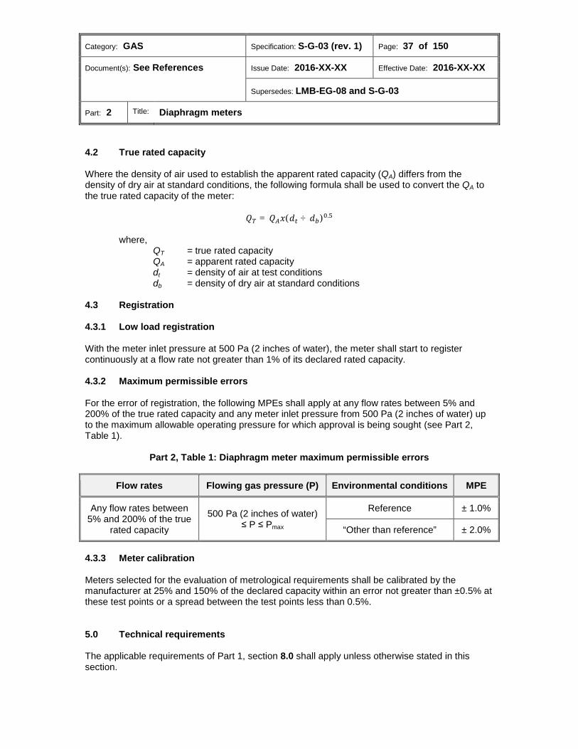
4.2 True rated capacity Where the density of air used to establish the apparent rated capacity (QA) differs from the density of dry air at standard conditions, the following formula shall be used to convert the QA to the true rated capacity of the meter:
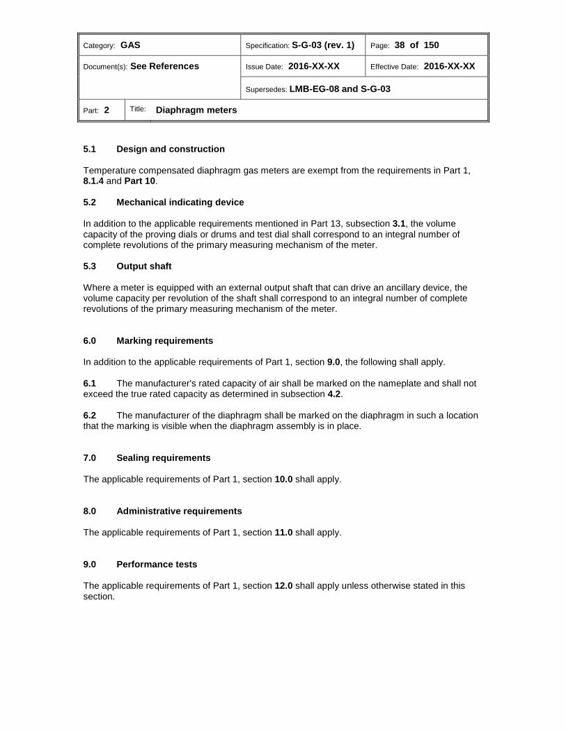
𝑄𝑇 = 𝑄𝐴𝑥(𝑑𝑡 ÷ 𝑑𝑏)0.5 where, QT = true rated capacity QA = apparent rated capacity dt = density of air at test conditions db = density of dry air at standard conditions 4.3 Registration 4.3.1 Low load registration With the meter inlet pressure at 500 Pa (2 inches of water), the meter shall start to register continuously at a flow rate not greater than 1% of its declared rated capacity. 4.3.2 Maximum permissible errors For the error of registration, the following MPEs shall apply at any flow rates between 5% and 200% of the true rated capacity and any meter inlet pressure from 500 Pa (2 inches of water) up to the maximum allowable operating pressure for which approval is being sought (see Part 2, Table 1).
Part 2, Table 1: Diaphragm meter maximum permissible errors
Flow rates Flowing gas pressure (P) Environmental conditions MPE
Any flow rates between 5% and 200% of the true
rated capacity 500 Pa (2 inches of water)
≤ P ≤ Pmax
Reference ± 1.0%
“Other than reference” ± 2.0%
4.3.3 Meter calibration Meters selected for the evaluation of metrological requirements shall be calibrated by the manufacturer at 25% and 150% of the declared capacity within an error not greater than ±0.5% at these test points or a spread between the test points less than 0.5%.
Technical requirements 5.0 The applicable requirements of Part 1, section 8.0 shall apply unless otherwise stated in this section.
Category: GAS Specification: S-G-03 (rev. 1) Page: 38 of 150
Document(s): See References Issue Date: 2016-XX-XX Effective Date: 2016-XX-XX
Supersedes: LMB-EG-08 and S-G-03
Part: 2 Title: Diaphragm meters
5.1 Design and construction Temperature compensated diaphragm gas meters are exempt from the requirements in Part 1, 8.1.4 and Part 10. 5.2 Mechanical indicating device In addition to the applicable requirements mentioned in Part 13, subsection 3.1, the volume capacity of the proving dials or drums and test dial shall correspond to an integral number of complete revolutions of the primary measuring mechanism of the meter. 5.3 Output shaft Where a meter is equipped with an external output shaft that can drive an ancillary device, the volume capacity per revolution of the shaft shall correspond to an integral number of complete revolutions of the primary measuring mechanism of the meter.
Marking requirements 6.0 In addition to the applicable requirements of Part 1, section 9.0, the following shall apply. 6.1 The manufacturer's rated capacity of air shall be marked on the nameplate and shall not exceed the true rated capacity as determined in subsection 4.2. 6.2 The manufacturer of the diaphragm shall be marked on the diaphragm in such a location that the marking is visible when the diaphragm assembly is in place.
Sealing requirements 7.0 The applicable requirements of Part 1, section 10.0 shall apply.
Administrative requirements 8.0 The applicable requirements of Part 1, section 11.0 shall apply.
Performance tests 9.0 The applicable requirements of Part 1, section 12.0 shall apply unless otherwise stated in this section.

Category: GAS Specification: S-G-03 (rev. 1) Page: 39 of 150
Document(s): See References Issue Date: 2016-XX-XX Effective Date: 2016-XX-XX
Supersedes: LMB-EG-08 and S-G-03
Part: 2 Title: Diaphragm meters
9.1 The following tests shall be conducted at reference environmental conditions:
(a) Tests to confirm apparent rated capacity;
(b) Low load registration tests;
(c) Load registration tests where flow rates shall be between 5% and 200% of the true rated capacity and any meter inlet pressure from 500 Pa (2 inches of water) up to the maximum allowable operating pressure for which approval is being sought (see Part 2, Table 2).
9.2 At “other than reference” environmental condition, load registration tests shall be conducted as specified in 9.1(c) (see Part 2, Table 2).
Part 2, Table 2: Diaphragm meter load registration tests
Environmental conditions Flow rates Flowing gas pressure (P)
Reference Any flow rates between 5% and 200% of the true rated capacity 500 Pa (2 inches of water) ≤ P ≤ Pmax
“Other than reference”
Category: GAS Specification: S-G-03 (rev. 1) Page: 40 of 150
Document(s): See References Issue Date: 2016-XX-XX Effective Date: 2016-XX-XX
Supersedes: LMB-EG-08 and S-G-03
Part: 3 Title: Rotary meters
Part 3: Rotary meters
Table of contents
Scope ............................................................................................................................... 41 1.0 Terminology .................................................................................................................... 41 2.0 Units ................................................................................................................................. 41 3.0 Metrological requirements ............................................................................................. 41 4.0
4.1 Starting differential pressure ............................................................................................. 41 4.2 Maximum permissible errors ............................................................................................ 41 Technical requirements ................................................................................................. 42 5.0
5.1 Provisions for proving ....................................................................................................... 42 Marking requirements .................................................................................................... 42 6.0 Sealing requirements ..................................................................................................... 42 7.0 Administrative requirements ......................................................................................... 43 8.0 Performance tests .......................................................................................................... 43 9.0
9.1 Operating conditions ......................................................................................................... 43 9.2 Evaluation tests ................................................................................................................ 43
Category: GAS Specification: S-G-03 (rev. 1) Page: 41 of 150
Document(s): See References Issue Date: 2016-XX-XX Effective Date: 2016-XX-XX
Supersedes: LMB-EG-08 and S-G-03
Part: 3 Title: Rotary meters
Scope 1.0 1.1 This part of the Specifications applies to all positive displacement rotary type gas meters submitted for approval. 1.2 Rotary meter bodies and measurement modules shall be approved under one approval where the modules are not interchangeable; otherwise, they shall carry separate approvals.
Terminology 2.0 Rotary meter (compteur à piston rotatifs) Volume measuring gas meter (positive displacement type) in which the measurement of the gas flow is effected by rotating members set on timing gears to transfer and integrate the flowing gas to a register.
Units 3.0 The applicable requirements of Part 1, section 6.0 shall apply unless otherwise stated in this section. 3.1 Rotary meter pressure bodies designed to accept both metric and imperial modules shall be exempt from the requirement in 6.1.1 of Part 1.
Metrological requirements 4.0 The applicable requirements of Part 1, section 7.0 shall apply unless otherwise stated in this section. 4.1 Starting differential pressure The starting differential pressure shall not exceed 25 Pa (0.1 inches of water). 4.2 Maximum permissible errors For the volume registration, the following MPEs shall apply between Qmin and Qmax: (see Part 3, Table 1).
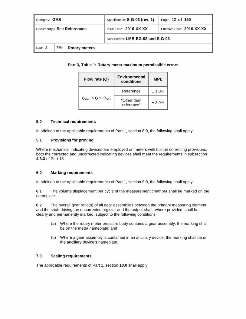
Category: GAS Specification: S-G-03 (rev. 1) Page: 42 of 150
Document(s): See References Issue Date: 2016-XX-XX Effective Date: 2016-XX-XX
Supersedes: LMB-EG-08 and S-G-03
Part: 3 Title: Rotary meters
Part 3, Table 1: Rotary meter maximum permissible errors
Flow rate (Q) Environmental conditions MPE
Qmin ≤ Q ≤ Qmax
Reference ± 1.0%
“Other than reference” ± 2.0%
Technical requirements 5.0 In addition to the applicable requirements of Part 1, section 8.0, the following shall apply. 5.1 Provisions for proving Where mechanical indicating devices are employed on meters with built-in correcting provisions, both the corrected and uncorrected indicating devices shall meet the requirements in subsection 4.3.3 of Part 13.
Marking requirements 6.0 In addition to the applicable requirements of Part 1, section 9.0, the following shall apply. 6.1 The volume displacement per cycle of the measurement chamber shall be marked on the nameplate. 6.2 The overall gear ratio(s) of all gear assemblies between the primary measuring element and the shaft driving the uncorrected register and the output shaft, where provided, shall be clearly and permanently marked, subject to the following conditions:
(a) Where the rotary meter pressure body contains a gear assembly, the marking shall be on the meter nameplate; and
(b) Where a gear assembly is contained in an ancillary device, the marking shall be on
the ancillary device’s nameplate.
Sealing requirements 7.0 The applicable requirements of Part 1, section 10.0 shall apply.
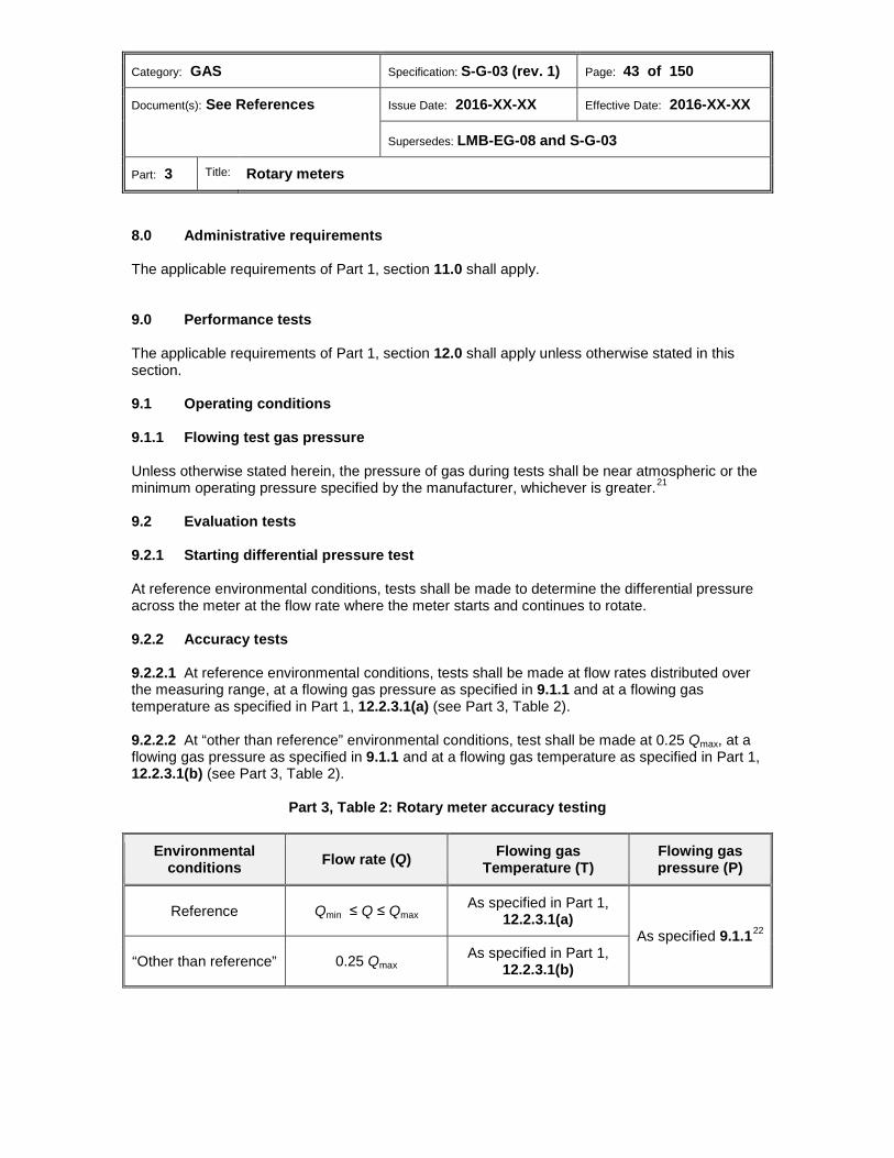
Category: GAS Specification: S-G-03 (rev. 1) Page: 43 of 150
Document(s): See References Issue Date: 2016-XX-XX Effective Date: 2016-XX-XX
Supersedes: LMB-EG-08 and S-G-03
Part: 3 Title: Rotary meters
Administrative requirements 8.0 The applicable requirements of Part 1, section 11.0 shall apply.
Performance tests 9.0 The applicable requirements of Part 1, section 12.0 shall apply unless otherwise stated in this section. 9.1 Operating conditions 9.1.1 Flowing test gas pressure Unless otherwise stated herein, the pressure of gas during tests shall be near atmospheric or the minimum operating pressure specified by the manufacturer, whichever is greater.21 9.2 Evaluation tests 9.2.1 Starting differential pressure test At reference environmental conditions, tests shall be made to determine the differential pressure across the meter at the flow rate where the meter starts and continues to rotate. 9.2.2 Accuracy tests 9.2.2.1 At reference environmental conditions, tests shall be made at flow rates distributed over the measuring range, at a flowing gas pressure as specified in 9.1.1 and at a flowing gas temperature as specified in Part 1, 12.2.3.1(a) (see Part 3, Table 2). 9.2.2.2 At “other than reference” environmental conditions, test shall be made at 0.25 Qmax, at a flowing gas pressure as specified in 9.1.1 and at a flowing gas temperature as specified in Part 1, 12.2.3.1(b) (see Part 3, Table 2).
Part 3, Table 2: Rotary meter accuracy testing
Environmental conditions Flow rate (Q) Flowing gas
Temperature (T) Flowing gas pressure (P)
Reference Qmin ≤ Q ≤ Qmax As specified in Part 1,
12.2.3.1(a) As specified 9.1.122
“Other than reference” 0.25 Qmax As specified in Part 1,
12.2.3.1(b)

Category: GAS Specification: S-G-03 (rev. 1) Page: 44 of 150
Document(s): See References Issue Date: 2016-XX-XX Effective Date: 2016-XX-XX
Supersedes: LMB-EG-08 and S-G-03
Part: 4 Title: Turbine meters
Part 4: Turbine meters
Table of contents
Scope ............................................................................................................................... 45 1.0 Terminology .................................................................................................................... 45 2.0 Units ................................................................................................................................. 45 3.0 Metrological requirements ............................................................................................. 45 4.0
4.1 Maximum permissible errors ............................................................................................ 45 4.2 Repeatability ..................................................................................................................... 46 4.3 Maximum peak-to-peak error ........................................................................................... 46 4.4 Effect of swirl .................................................................................................................... 46 4.5 Measuring cartridge interchangeability ............................................................................. 46 Technical requirements ................................................................................................. 46 5.0
5.1 Pulse output ...................................................................................................................... 46 Marking requirements .................................................................................................... 46 6.0 Sealing requirements ..................................................................................................... 47 7.0 Administrative requirements ......................................................................................... 47 8.0 Performance tests .......................................................................................................... 47 9.0
9.1 Operating conditions ......................................................................................................... 47 9.2 Flow rate test points ......................................................................................................... 48 9.3 Test mediums ................................................................................................................... 48 9.4 Temperature measurement .............................................................................................. 48 9.5 Pressure measurement .................................................................................................... 49 9.6 Evaluation tests ................................................................................................................ 49
Category: GAS Specification: S-G-03 (rev. 1) Page: 45 of 150
Document(s): See References Issue Date: 2016-XX-XX Effective Date: 2016-XX-XX
Supersedes: LMB-EG-08 and S-G-03
Part: 4 Title: Turbine meters
Scope 1.0 This part of the Specifications applies to axial flow turbine type gas meters submitted for approval.
Terminology 2.0 High operating pressure (pression de fonctionnement élevée) Any gas or air pressure over 5000 kPa (≈720 psig). Low operating pressure (pression de fonctionnement basse) Any gas or air pressure below 400 kPa (≈50 psig). Medium operating pressure (pression de fonctionnement moyenne) Any gas or air pressure from 400 to 5000 kPa (≈50 to ≈720 psig). Measurement cartridge (cartouche de mesure) An internal assembly that is removable from some meters and includes the measurement components, but excludes the meter body. Turbine meter (compteur à turbine) A volume measuring gas meter (inferential type) in which the measurement of the gas flow is effected by a turbine blade assembly that is mounted in a case which rotates as the gas flows past the turbine blades. The turbine meter utilizes the force (kinetic energy) of the flowing gas to drive the measurement turbine blade.
Units 3.0 The applicable requirements of Part 1, section 6.0 shall apply.
Metrological requirements 4.0 The applicable requirements of Part 1, section 7.0 shall apply unless otherwise stated in this section. 4.1 Maximum permissible errors For the uncorrected volume registration, the MPEs in Part 4, Table 1 shall apply:
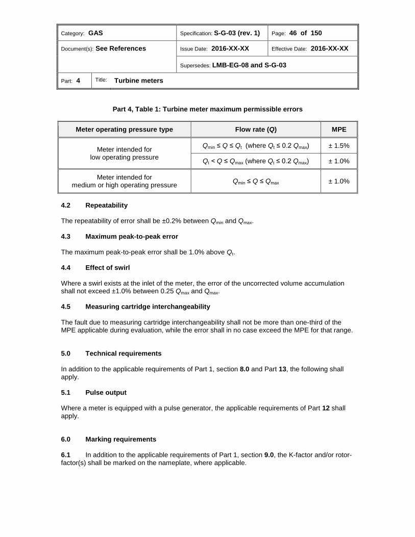
Category: GAS Specification: S-G-03 (rev. 1) Page: 46 of 150
Document(s): See References Issue Date: 2016-XX-XX Effective Date: 2016-XX-XX
Supersedes: LMB-EG-08 and S-G-03
Part: 4 Title: Turbine meters
Part 4, Table 1: Turbine meter maximum permissible errors
Meter operating pressure type Flow rate (Q) MPE
Meter intended for low operating pressure
Qmin ≤ Q ≤ Qt (where Qt ≤ 0.2 Qmax) ± 1.5%
Qt ˂ Q ≤ Qmax (where Qt ≤ 0.2 Qmax) ± 1.0%
Meter intended for medium or high operating pressure Qmin ≤ Q ≤ Qmax ± 1.0%
4.2 Repeatability The repeatability of error shall be ±0.2% between Qmin and Qmax. 4.3 Maximum peak-to-peak error The maximum peak-to-peak error shall be 1.0% above Qt. 4.4 Effect of swirl Where a swirl exists at the inlet of the meter, the error of the uncorrected volume accumulation shall not exceed ±1.0% between 0.25 Qmax and Qmax. 4.5 Measuring cartridge interchangeability The fault due to measuring cartridge interchangeability shall not be more than one-third of the MPE applicable during evaluation, while the error shall in no case exceed the MPE for that range.
Technical requirements 5.0 In addition to the applicable requirements of Part 1, section 8.0 and Part 13, the following shall apply. 5.1 Pulse output Where a meter is equipped with a pulse generator, the applicable requirements of Part 12 shall apply.
Marking requirements 6.0 6.1 In addition to the applicable requirements of Part 1, section 9.0, the K-factor and/or rotor-factor(s) shall be marked on the nameplate, where applicable.
Category: GAS Specification: S-G-03 (rev. 1) Page: 47 of 150
Document(s): See References Issue Date: 2016-XX-XX Effective Date: 2016-XX-XX
Supersedes: LMB-EG-08 and S-G-03
Part: 4 Title: Turbine meters
6.2 Where a meter is designed for operation with interchangeable cartridges, the markings required in Part 1, 9.1(a), (b), (c), (d) and (j) and subsection 9.4 shall appear on the meter case and the interchangeable cartridge. 6.3 Where change gears are provided, the number of teeth shall be permanently marked on each of the change gears in such a location as to be legible with the change gears in place.
Sealing requirements 7.0 The applicable requirements of Part 1, section 10.0 shall apply.
Administrative requirements 8.0 The applicable requirements of Part 1, section 11.0 shall apply.
Performance tests 9.0 The applicable requirements of Part 1, section 12.0 shall apply unless otherwise stated in this section. 9.1 Operating conditions 9.1.1 Flowing gas pressure 9.1.1.1 Where gas meters are intended to operate at low pressure, the pressure of gas during tests shall be near atmospheric (see Part 4, Table 2). 9.1.1.2 Where gas meters are intended to operate at medium pressure, the pressure of gas during tests shall be approximately minimum and maximum flowing gas pressure (see Part 4, Table 2). 9.1.1.3 Where gas meters are intended to operate at high pressure, the pressure of gas during tests shall be any pressure between 5000 kPa (720 psig) and the maximum operating pressure (see Part 4, Table 2).

Category: GAS Specification: S-G-03 (rev. 1) Page: 48 of 150
Document(s): See References Issue Date: 2016-XX-XX Effective Date: 2016-XX-XX
Supersedes: LMB-EG-08 and S-G-03
Part: 4 Title: Turbine meters
Part 4, Table 2: Turbine meter flowing gas test pressures
Meter operating pressure type Flowing gas test pressure
Meter intended for low operating pressure Atmospheric
Meter intended for medium operating pressure Approximately minimum and maximum operating pressure
Meter intended for high operating pressure Any pressure between 5000 kPa (720 psig) and the maximum operating pressure
9.2 Flow rate test points For each flow rate at which the meter is tested, the peak-to-peak fluctuations in flow rate shall be minimized and in no case shall exceed 2% of the average flow rate. 9.3 Test mediums 9.3.1 Where gas meters are intended to operate at low pressure, the test medium shall be air (see Part 4, Table 3). 9.3.2 Where gas meters are intended to operate at medium or high pressure, the test medium shall be gas (see Part 4, Table 3).
Part 4, Table 3: Turbine meter test mediums
Meter operating pressure type Test medium
Meter intended for low operating pressure Air
Meter intended for medium operating pressure Gas
Meter intended for high operating pressure Gas
9.4 Temperature measurement The temperature of the air flowing through the meter shall be sensed at a point on the downstream side of the meter at a distance recommended by the manufacturer but no further than five times the nominal pipe diameter.

Category: GAS Specification: S-G-03 (rev. 1) Page: 49 of 150
Document(s): See References Issue Date: 2016-XX-XX Effective Date: 2016-XX-XX
Supersedes: LMB-EG-08 and S-G-03
Part: 4 Title: Turbine meters
9.5 Pressure measurement Where a pressure tap is located on the meter body, it shall be used as a pressure sensing point during testing unless otherwise recommended by the manufacturer. In all other cases, pressure shall be measured as close as possible to the inlet of the meter. 9.6 Evaluation tests 9.6.1 Accuracy testing 9.6.1.1 At reference environmental conditions, tests shall be made at flow rates distributed over the measuring range, at test mediums as specified in 9.3 and operating conditions as mentioned in subsection 9.1 (see Part 4, Table 4). 9.6.1.2 At “other than reference” environmental conditions, tests shall be made with a flow rate of 0.25Qmax, at test mediums as specified in subsection 9.3 and operating conditions as mentioned in subsection 9.1 (see Part 4, Table 4).
Part 4, Table 4: Turbine meter accuracy testing
Meter operating pressure type
Test Medium
Flowing gas pressure (P)
Environmental conditions Flow rate (Q)
Meter intended for low operating
pressure Air Atmospheric
Reference Qmin ≤ Q ≤ Qmax
“Other than reference” 0.25Qmax
Meter intended for medium operating pressure
Gas Approximately minimum and
maximum operating pressure
Reference Qmin ≤ Q ≤ Qmax
“Other than reference” 0.25Qmax
Meter intended for high operating
pressure Gas
Any pressure between 5000 kPa (720 psig) and the
maximum operating pressure
Reference Qmin ≤ Q ≤ Qmax
“Other than reference” 0.25Qmax
9.6.2 Swirl susceptibility testing 9.6.2.1 The requirements in Part 1, 12.5.8.4 shall apply unless otherwise stated in this section. 9.6.2.2 At reference environmental test conditions, tests shall be made with flow rates at 0.25 Qmax, 0.4 Qmax and Qmax, with test mediums as specified in subsection 9.3 and at operating conditions as mentioned in subsection 9.1 (see Part 4, Table 5).
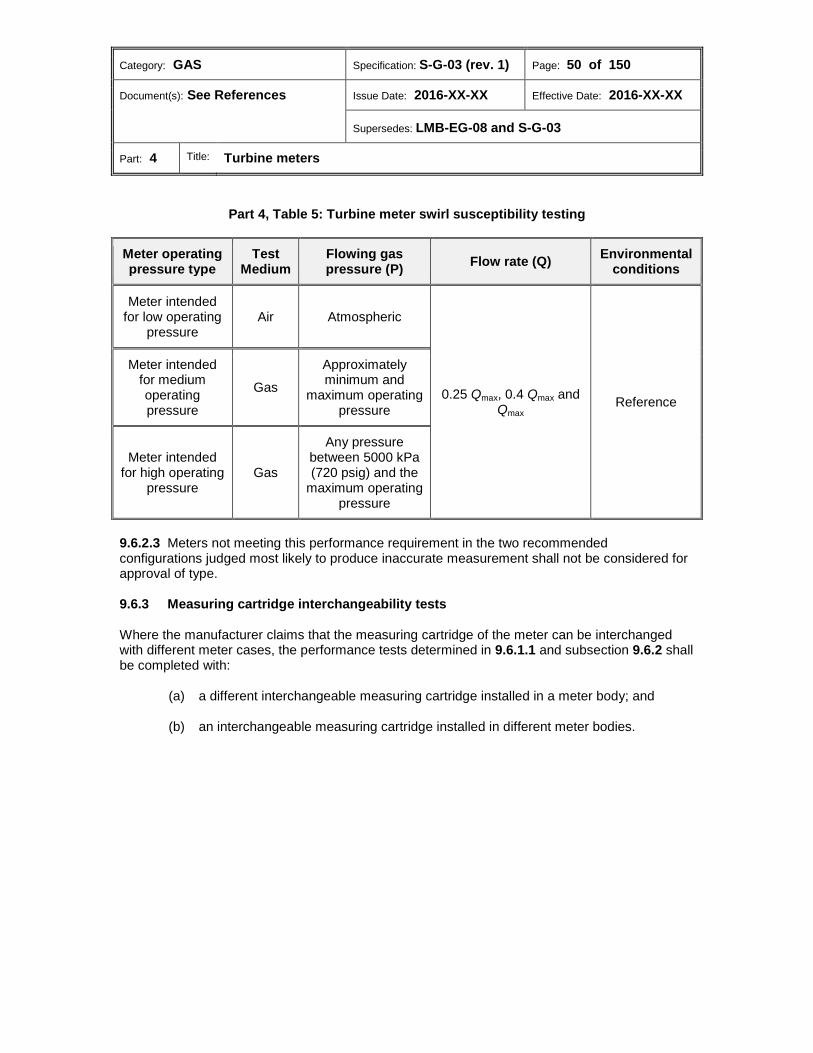
Category: GAS Specification: S-G-03 (rev. 1) Page: 50 of 150
Document(s): See References Issue Date: 2016-XX-XX Effective Date: 2016-XX-XX
Supersedes: LMB-EG-08 and S-G-03
Part: 4 Title: Turbine meters
Part 4, Table 5: Turbine meter swirl susceptibility testing
Meter operating pressure type
Test Medium
Flowing gas pressure (P) Flow rate (Q) Environmental
conditions
Meter intended for low operating
pressure Air Atmospheric
0.25 Qmax, 0.4 Qmax and Qmax
Reference
Meter intended for medium operating pressure
Gas Approximately minimum and
maximum operating pressure
Meter intended for high operating
pressure Gas
Any pressure between 5000 kPa (720 psig) and the
maximum operating pressure
9.6.2.3 Meters not meeting this performance requirement in the two recommended configurations judged most likely to produce inaccurate measurement shall not be considered for approval of type. 9.6.3 Measuring cartridge interchangeability tests Where the manufacturer claims that the measuring cartridge of the meter can be interchanged with different meter cases, the performance tests determined in 9.6.1.1 and subsection 9.6.2 shall be completed with:
(a) a different interchangeable measuring cartridge installed in a meter body; and
(b) an interchangeable measuring cartridge installed in different meter bodies.
Category: GAS Specification: S-G-03 (rev. 1) Page: 51 of 150
Document(s): See References Issue Date: 2016-XX-XX Effective Date: 2016-XX-XX
Supersedes: LMB-EG-08 and S-G-03
Part: 5 Title: Orifice meters
Part 5: Orifice meters
Table of contents
Scope ............................................................................................................................... 52 1.0 Terminology .................................................................................................................... 52 2.0 Units ................................................................................................................................. 52 3.0 Metrological requirements ............................................................................................. 52 4.0
4.1 Dimensional measurements ............................................................................................. 52 4.2 Displacement of the orifice plate ...................................................................................... 52 Technical requirements ................................................................................................. 52 5.0
5.1 General ............................................................................................................................. 52 Marking requirements .................................................................................................... 53 6.0
6.1 Nameplate ........................................................................................................................ 53 6.2 Beta ratio .......................................................................................................................... 53 6.3 Orifice plate ....................................................................................................................... 54 Sealing requirements ..................................................................................................... 54 7.0 Administrative requirements ......................................................................................... 54 8.0
8.1 Application for approval .................................................................................................... 54 Performance tests .......................................................................................................... 54 9.0
9.1 Test conditions.................................................................................................................. 54 9.2 Evaluation tests ................................................................................................................ 55
Category: GAS Specification: S-G-03 (rev. 1) Page: 52 of 150
Document(s): See References Issue Date: 2016-XX-XX Effective Date: 2016-XX-XX
Supersedes: LMB-EG-08 and S-G-03
Part: 5 Title: Orifice meters
Scope 1.0 This part of the Specifications applies to the primary elements of orifice meters used to measure natural gas and submitted for approval.23
Terminology 2.0 Orifice meter (AGA Report No. 3) (compteur à orifice) A fluid flow measuring device that produces a differential pressure to infer flow rate.
Units 3.0 The applicable requirements of Part 1, section 6.0 shall apply.
Metrological requirements 4.0 The applicable requirements of Part 1, section 7.0 shall apply unless otherwise stated in this section. 4.1 Dimensional measurements The dimensional measurements as specified in subsection 9.2.1 shall not exceed the tolerances set out in AGA Report No.3: Orifice Metering of Natural Gas and Other Related Hydrocarbon Fluids, Part 2: Specification and Installation Requirements, (Fourth edition, 2000). 4.2 Displacement of the orifice plate The displacement of the orifice plate caused by compressibility of the sealing material shall be such that the tolerance for a beta ratio of 0.70, as set out in Figure 2-3 of AGA Report No. 3, Part 2, is not exceeded under maximum load.
Technical requirements 5.0 In addition to the applicable requirements of Part 1, section 8.0, the following shall apply. 5.1 General These specifications adopt the requirements set out in AGA Report No.3: Orifice Metering of Natural Gas and Other Related Hydrocarbon Fluids, Part 2: Specification and Installation Requirements, (Fourth edition, 2000), except as delineated below.
Category: GAS Specification: S-G-03 (rev. 1) Page: 53 of 150
Document(s): See References Issue Date: 2016-XX-XX Effective Date: 2016-XX-XX
Supersedes: LMB-EG-08 and S-G-03
Part: 5 Title: Orifice meters
5.1.1 Orifice plates Subsection 2.4 of AGA Report No.3 Part 2 shall apply with the exception of clause 2.4.2. The recommendation for the limits of the beta ratio shall be mandatory. The orifice shall be circular in shape. 5.1.2 Meter tubes Subsection 2.5 of AGA Report No.3 Part 2 shall apply. 5.1.3 Orifice flanges In addition to the requirements of subsection 2.5.2 of AGA Report No.3 Part 2, the face of each orifice flange shall be perpendicular to the axis of each tube section. 5.1.4 Gaskets 5.1.4.1 The design and material used for sealing the orifice plate in a meter shall be such as to ensure that in operation the thrust caused by total force due to the maximum differential pressure shall not displace the orifice plate to the extent that the allowable tolerances for the pressure tap hole location specified in subsection 2.5.4 of AGA Report No. 3 Part 2 are exceeded under dynamic conditions. 5.1.4.2 Where the sealing material is bonded to the orifice plate, a blank plate complete with identical sealing material bonded to it shall be supplied by the manufacturer.
Marking requirements 6.0 In addition to the applicable requirements of Part 1, section 9.0, the following shall apply. 6.1 Nameplate The following information shall be provided on a nameplate located on the orifice fitting where one is used, or, otherwise, on or adjacent to the orifice flange:
(a) Published inside diameter of meter tubes;
(b) Maximum operating pressure;
(c) Nominal thickness of the orifice plate to be used;
(d) Nominal thickness of the orifice sealing ring(s) or gaskets or orifice plate carrier to be used.
6.2 Beta ratio A nameplate, tag, sticker or other suitable means shall be provided for marking the maximum permissible beta ratio.

Category: GAS Specification: S-G-03 (rev. 1) Page: 54 of 150
Document(s): See References Issue Date: 2016-XX-XX Effective Date: 2016-XX-XX
Supersedes: LMB-EG-08 and S-G-03
Part: 5 Title: Orifice meters
6.3 Orifice plate The markings on the orifice plate shall be made by engraving, chemical means, or equivalent, which will ensure indelible marking without distorting the plate. 6.3.1 Orifice nominal diameter The manufacturer of the orifice plate shall mark the nominal diameter of the orifice on the downstream side of the outer perimeter of the orifice plate or on the downstream side of the orifice plate handle, where present. The nominal diameter shall be marked to the nearest one thousandth of an inch. 6.3.2 Contractor marks Each orifice plate shall provide space for the contractor to mark it in a manner which identifies the contractor and the plate number.
Sealing requirements 7.0 The applicable requirements of Part 1, section 10.0 shall apply.
Administrative requirements 8.0 In addition to the applicable requirements of Part 1, section 11.0, the following shall apply. 8.1 Application for approval An attestation of compliance and supporting test data from an MC-recognized authority shall be supplied with the application showing that the requirements specified in section 4.0 have been met.
Performance tests 9.0 9.1 Test conditions All measurements shall be made at reference ambient temperature as specified in Part 1, 12.2.1(a).
Category: GAS Specification: S-G-03 (rev. 1) Page: 55 of 150
Document(s): See References Issue Date: 2016-XX-XX Effective Date: 2016-XX-XX
Supersedes: LMB-EG-08 and S-G-03
Part: 5 Title: Orifice meters
9.2 Evaluation tests 9.2.1 Dimensional measurements Measurements shall be made to establish the following:
(a) Dimensions of the meter tubes;
(b) Orifice fittings;
(c) Pressure tap holes and their locations in relation to the orifice plate faces;
(d) Orifice plate and surface roughness;
(e) Thermometer well location as set out in AGA Report No. 3 Part 2.

Category: GAS Specification: S-G-03 (rev. 1) Page: 56 of 150
Document(s): See References Issue Date: 2016-XX-XX Effective Date: 2016-XX-XX
Supersedes: LMB-EG-08 and S-G-03
Part: 6 Title: Mass flow meters
Part 6: Mass flow meters
Table of contents
Scope ............................................................................................................................... 57 1.0 Terminology .................................................................................................................... 57 2.0 Units ................................................................................................................................. 57 3.0 Metrological requirements ............................................................................................. 57 4.0
4.1 Maximum permissible errors ............................................................................................ 57 4.2 Repeatability ..................................................................................................................... 58 4.3 Maximum peak-to-peak error ........................................................................................... 58 Technical requirements ................................................................................................. 58 5.0 Marking requirements .................................................................................................... 58 6.0 Sealing requirements ..................................................................................................... 58 7.0 Administrative requirements ......................................................................................... 58 8.0 Performance tests .......................................................................................................... 59 9.0
9.1 Flow rate test points ......................................................................................................... 59 9.2 Test gas ............................................................................................................................ 59 9.3 Evaluation tests ................................................................................................................ 59
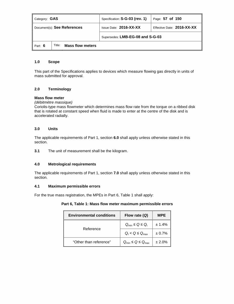
Category: GAS Specification: S-G-03 (rev. 1) Page: 57 of 150
Document(s): See References Issue Date: 2016-XX-XX Effective Date: 2016-XX-XX
Supersedes: LMB-EG-08 and S-G-03
Part: 6 Title: Mass flow meters
Scope 1.0 This part of the Specifications applies to devices which measure flowing gas directly in units of mass submitted for approval.
Terminology 2.0 Mass flow meter (débitmètre massique) Coriolis-type mass flowmeter which determines mass flow rate from the torque on a ribbed disk that is rotated at constant speed when fluid is made to enter at the centre of the disk and is accelerated radially.
Units 3.0 The applicable requirements of Part 1, section 6.0 shall apply unless otherwise stated in this section. 3.1 The unit of measurement shall be the kilogram.
Metrological requirements 4.0 The applicable requirements of Part 1, section 7.0 shall apply unless otherwise stated in this section. 4.1 Maximum permissible errors For the true mass registration, the MPEs in Part 6, Table 1 shall apply:
Part 6, Table 1: Mass flow meter maximum permissible errors
Environmental conditions Flow rate (Q) MPE
Reference Qmin ≤ Q ≤ Qt ± 1.4%
Qt ˂ Q ≤ Qmax ± 0.7%
“Other than reference” Qmin ≤ Q ≤ Qmax ± 2.0%

Category: GAS Specification: S-G-03 (rev. 1) Page: 58 of 150
Document(s): See References Issue Date: 2016-XX-XX Effective Date: 2016-XX-XX
Supersedes: LMB-EG-08 and S-G-03
Part: 6 Title: Mass flow meters
4.2 Repeatability The repeatability of error shall be as specified in Part 6, Table 2.
Part 6, Table 2: Mass flow meter repeatability
Flow rate (Q) Repeatability
Qmin ≤ Q ≤ Qt ± 1.0% of reading
Qt ˂ Q ≤ Qmax ± 0.35% of reading
4.3 Maximum peak-to-peak error The maximum peak-to-peak error shall be as specified in Part 6, Table 3.
Part 6, Table 3: Mass flow meter maximum peak-to-peak error
Flow rate (Q) Maximum peak-to-peak error
Qmin ≤ Q ≤ Qt 1.4% of reading
Qt ˂ Q ≤ Qmax 0.7% of reading
Technical requirements 5.0 The applicable requirements of Part 1, section 8.0 shall apply.
Marking requirements 6.0 In addition to the applicable requirements of Part 1, section 9.0, the maximum mass flow rate shall be marked on the nameplate.
Sealing requirements 7.0 The applicable requirements of Part 1, section 10.0 shall apply.
Administrative requirements 8.0 The applicable requirements of Part 1, section 11.0 shall apply.
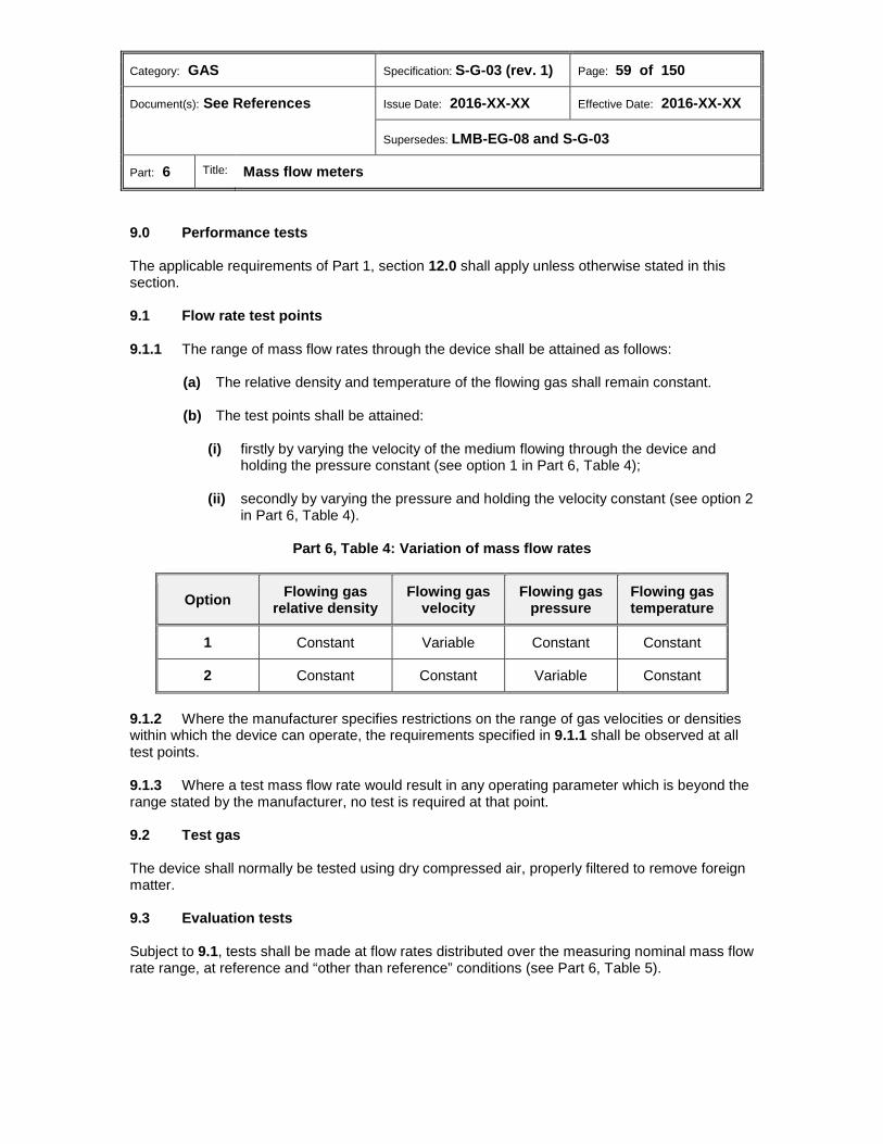
Category: GAS Specification: S-G-03 (rev. 1) Page: 59 of 150
Document(s): See References Issue Date: 2016-XX-XX Effective Date: 2016-XX-XX
Supersedes: LMB-EG-08 and S-G-03
Part: 6 Title: Mass flow meters
Performance tests 9.0 The applicable requirements of Part 1, section 12.0 shall apply unless otherwise stated in this section. 9.1 Flow rate test points 9.1.1 The range of mass flow rates through the device shall be attained as follows:
(a) The relative density and temperature of the flowing gas shall remain constant.
(b) The test points shall be attained:
(i) firstly by varying the velocity of the medium flowing through the device and holding the pressure constant (see option 1 in Part 6, Table 4);
(ii) secondly by varying the pressure and holding the velocity constant (see option 2 in Part 6, Table 4).
Part 6, Table 4: Variation of mass flow rates
Option Flowing gas relative density
Flowing gas velocity
Flowing gas pressure
Flowing gas temperature
1 Constant Variable Constant Constant
2 Constant Constant Variable Constant
9.1.2 Where the manufacturer specifies restrictions on the range of gas velocities or densities within which the device can operate, the requirements specified in 9.1.1 shall be observed at all test points. 9.1.3 Where a test mass flow rate would result in any operating parameter which is beyond the range stated by the manufacturer, no test is required at that point. 9.2 Test gas The device shall normally be tested using dry compressed air, properly filtered to remove foreign matter. 9.3 Evaluation tests Subject to 9.1, tests shall be made at flow rates distributed over the measuring nominal mass flow rate range, at reference and “other than reference” conditions (see Part 6, Table 5).
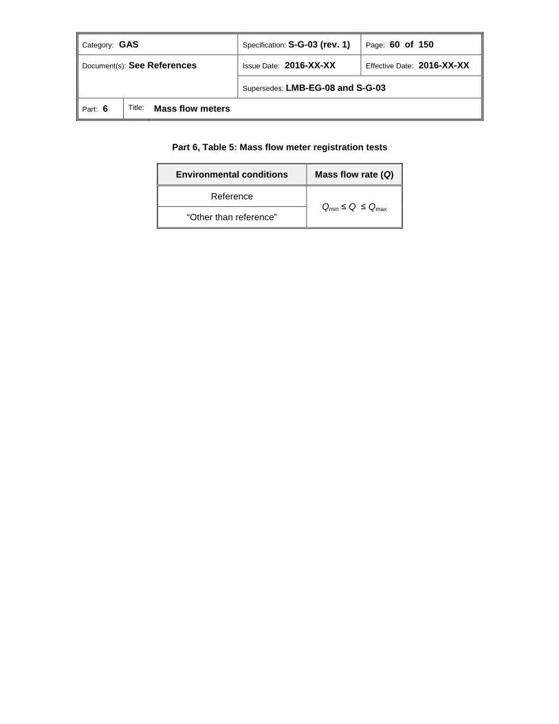
Category: GAS Specification: S-G-03 (rev. 1) Page: 60 of 150
Document(s): See References Issue Date: 2016-XX-XX Effective Date: 2016-XX-XX
Supersedes: LMB-EG-08 and S-G-03
Part: 6 Title: Mass flow meters
Part 6, Table 5: Mass flow meter registration tests
Environmental conditions Mass flow rate (Q)
Reference Qmin ≤ Q ≤ Qmax
“Other than reference”

Category: GAS Specification: S-G-03 (rev. 1) Page: 61 of 150
Document(s): See References Issue Date: 20XX-XX-XX Effective Date: 20XX-XX-XX
Supersedes: LMB-EG-08 and S-G-03
Part: 7 Title: Ultrasonic meters
Part 7: Ultrasonic meters
The approval requirements concerning ultrasonic gas meters which operate by determining the difference in transit times of bursts of ultrasonic energy travelling in the upstream and downstream direction are established in PS-G-06 - Provisional Specifications for the Approval, Verification, Reverification, Installation and Use of Ultrasonic Meters [link 8].
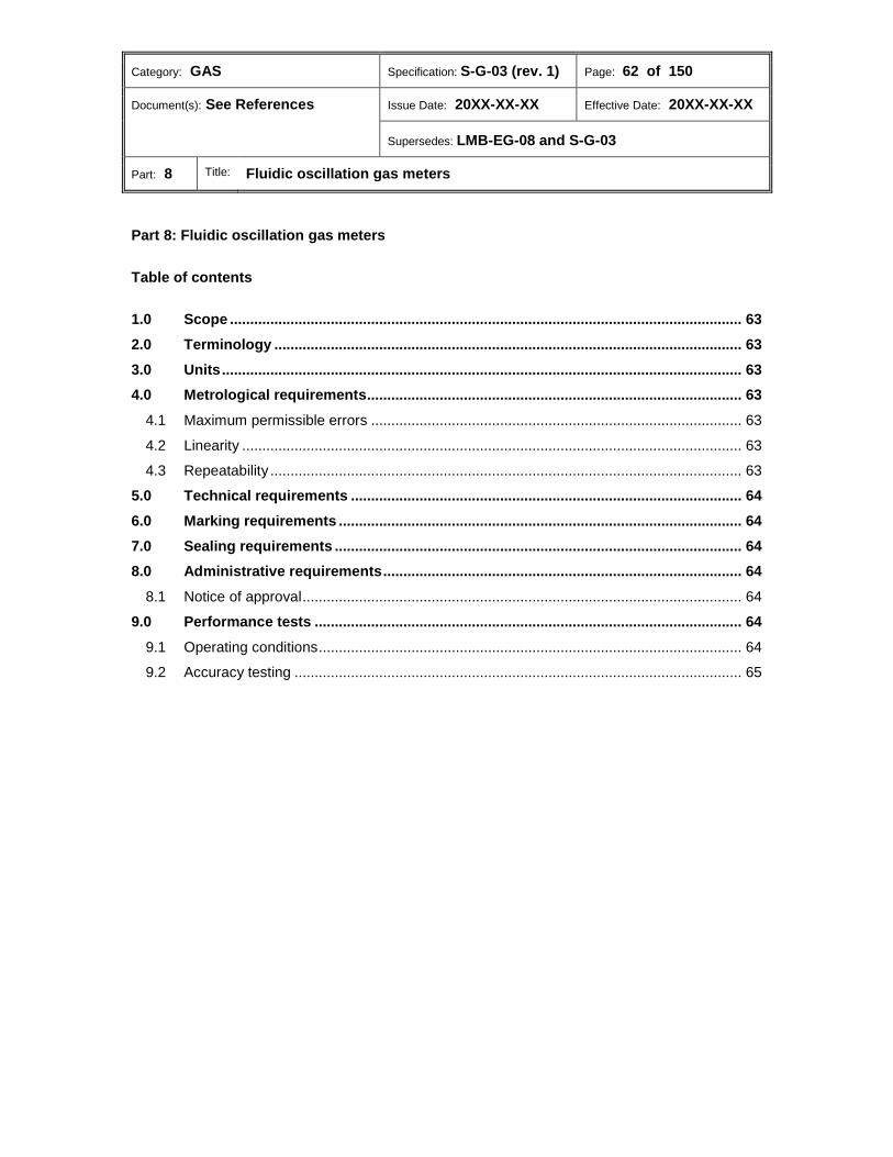
Category: GAS Specification: S-G-03 (rev. 1) Page: 62 of 150
Document(s): See References Issue Date: 20XX-XX-XX Effective Date: 20XX-XX-XX
Supersedes: LMB-EG-08 and S-G-03
Part: 8 Title: Fluidic oscillation gas meters
Part 8: Fluidic oscillation gas meters
Table of contents
Scope ............................................................................................................................... 63 1.0 Terminology .................................................................................................................... 63 2.0 Units ................................................................................................................................. 63 3.0 Metrological requirements ............................................................................................. 63 4.0
4.1 Maximum permissible errors ............................................................................................ 63 4.2 Linearity ............................................................................................................................ 63 4.3 Repeatability ..................................................................................................................... 63 Technical requirements ................................................................................................. 64 5.0 Marking requirements .................................................................................................... 64 6.0 Sealing requirements ..................................................................................................... 64 7.0 Administrative requirements ......................................................................................... 64 8.0
8.1 Notice of approval ............................................................................................................. 64 Performance tests .......................................................................................................... 64 9.0
9.1 Operating conditions ......................................................................................................... 64 9.2 Accuracy testing ............................................................................................................... 65

Category: GAS Specification: S-G-03 (rev. 1) Page: 63 of 150
Document(s): See References Issue Date: 20XX-XX-XX Effective Date: 20XX-XX-XX
Supersedes: LMB-EG-08 and S-G-03
Part: 8 Title: Fluidic oscillation gas meters
Scope 1.0 This part of the Specifications applies to fluidic oscillation gas meters submitted for approval and which operate by integrating gas flow through the detection of a gas jet’s oscillation frequency.
Terminology 2.0 Fluidic oscillation meter (compteur de gaz à oscillateur fluidique) A meter consisting of a meter body designed to condition gas flow into jet formation (flow conditioner and jet nozzle), a fluidic oscillation chamber (flow obstacle and sensors) and associated signal processing circuitry.
Units 3.0 The applicable requirements of Part 1, section 6.0 shall apply.
Metrological requirements 4.0 The applicable requirements of Part 1, section 7.0 shall apply unless otherwise stated in this section. 4.1 Maximum permissible errors The MPEs in Part 8, Table 1 shall apply between Qmin and Qmax.
Part 8, Table 1: Fluidic oscillation meter maximum permissible errors
Environmental conditions Flow rate (Q) MPE
Reference Qmin ≤ Q ≤ Qmax ± 1.0%
“Other than reference”
4.2 Linearity The linearity of error shall not exceed ± 0.5% between Qmin and Qmax. 4.3 Repeatability The repeatability of error shall not exceed ± 0.2% between Qmin and Qmax.

Category: GAS Specification: S-G-03 (rev. 1) Page: 64 of 150
Document(s): See References Issue Date: 20XX-XX-XX Effective Date: 20XX-XX-XX
Supersedes: LMB-EG-08 and S-G-03
Part: 8 Title: Fluidic oscillation gas meters
Technical requirements 5.0 The applicable requirements of Part 1, section 8.0 shall apply unless otherwise stated in this section. 5.1 A pressure tap shall be located on the meter body. 5.2 Where the meter incorporates provisions for converting volume to base conditions of temperature and pressure, the meter shall be capable of registering both converted and unconverted volume.
Marking requirements 6.0 The applicable requirements of Part 1, section 9.0 shall apply.
Sealing requirements 7.0 The applicable requirements of Part 1, section 10.0 shall apply.
Administrative requirements 8.0 In addition to the applicable requirements of Part 1, section 11.0, the following apply. 8.1 Notice of approval Where it can be shown that a meter’s accuracy is susceptible to flow pulsations, the NOA shall indicate the appropriate means to use to reduce the intensity of such disturbances to a level which will not cause the meter’s accuracy to exceed the MPE specified in subsection 4.1.
Performance tests 9.0 The applicable requirements of Part 1, section 12.0 shall apply unless otherwise stated in this section. 9.1 Operating conditions 9.1.1 Flowing test gas pressure The pressure of flowing gas during tests shall be any pressure up to the maximum operating pressure specified by the manufacturer.

Category: GAS Specification: S-G-03 (rev. 1) Page: 65 of 150
Document(s): See References Issue Date: 20XX-XX-XX Effective Date: 20XX-XX-XX
Supersedes: LMB-EG-08 and S-G-03
Part: 8 Title: Fluidic oscillation gas meters
9.2 Accuracy testing 9.2.1 At reference environmental conditions, tests shall be made at flow rates distributed over the measuring range and at operating conditions as stated in subsection 9.1 (see Part 8, Table 2). 9.2.2 At “other than reference” environmental conditions, tests shall be made at 0.25 Qmax and at operating conditions as specified in subsection 9.1 (see Part 8, Table 2).
Part 8, Table 2: Fluidic oscillation gas meter accuracy testing
Operating conditions Environmental conditions Flow rate (Q)
As specified in 9.1 Reference Qmin ≤ Q ≤ Qmax
“Other than reference” 0.25 Qmax
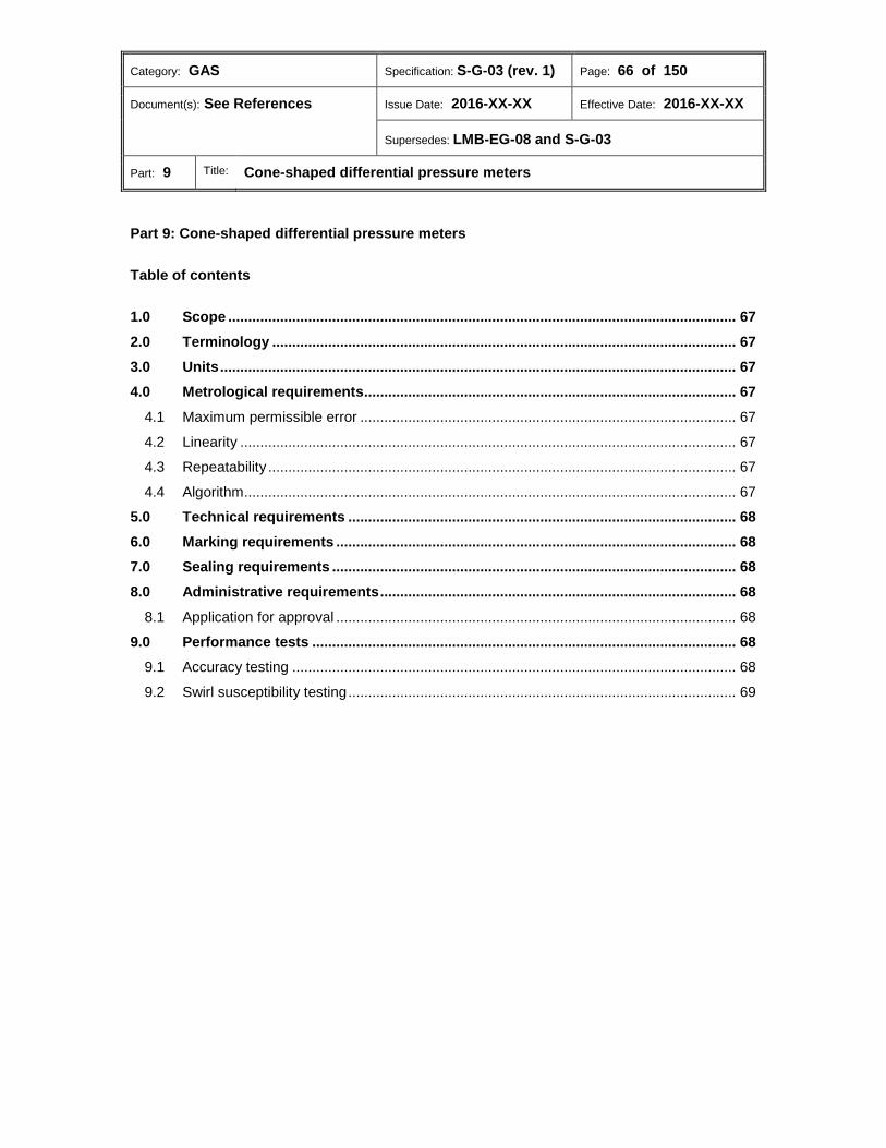
Category: GAS Specification: S-G-03 (rev. 1) Page: 66 of 150
Document(s): See References Issue Date: 2016-XX-XX Effective Date: 2016-XX-XX
Supersedes: LMB-EG-08 and S-G-03
Part: 9 Title: Cone-shaped differential pressure meters
Part 9: Cone-shaped differential pressure meters
Table of contents
Scope ............................................................................................................................... 67 1.0 Terminology .................................................................................................................... 67 2.0 Units ................................................................................................................................. 67 3.0 Metrological requirements ............................................................................................. 67 4.0
4.1 Maximum permissible error .............................................................................................. 67 4.2 Linearity ............................................................................................................................ 67 4.3 Repeatability ..................................................................................................................... 67 4.4 Algorithm ........................................................................................................................... 67 Technical requirements ................................................................................................. 68 5.0 Marking requirements .................................................................................................... 68 6.0 Sealing requirements ..................................................................................................... 68 7.0 Administrative requirements ......................................................................................... 68 8.0
8.1 Application for approval .................................................................................................... 68 Performance tests .......................................................................................................... 68 9.0
9.1 Accuracy testing ............................................................................................................... 68 9.2 Swirl susceptibility testing ................................................................................................. 69

Category: GAS Specification: S-G-03 (rev. 1) Page: 67 of 150
Document(s): See References Issue Date: 2016-XX-XX Effective Date: 2016-XX-XX
Supersedes: LMB-EG-08 and S-G-03
Part: 9 Title: Cone-shaped differential pressure meters
Scope 1.0 This part of the Specifications applies to cone-shaped differential pressure (CSDP) meters submitted for approval.
Terminology 2.0 Cone-shaped differential pressure meter (débitmètre à cône de type différentiel) A meter consisting of a cone-shaped element placed at the centre of the pipe, leaving an annular space for the passage of fluid which causes the velocity of the flowing fluid to change. A change in velocity occurs whenever there is a change in flow cross-section (i.e., with a decrease in velocity, an increase in pressure). The differential pressure generated is used to calculate the flow rate.
Units 3.0 The applicable requirements of Part 1, section 6.0 shall apply.
Metrological requirements 4.0 The applicable requirements of Part 1, section 7.0 shall apply unless otherwise stated in this section. 4.1 Maximum permissible error The MPE shall not exceed ± 1.0% between Qmin and Qmax. 4.2 Linearity The linearity shall not exceed ± 0.5% between Qmin and Qmax. 4.3 Repeatability
The repeatability of errors shall not exceed ± 0.2% between Qmin and Qmax. 4.4 Algorithm 4.4.1 Subject to 4.4.2, the algorithm used to translate the primary measurements of pressure and temperature into volumetric flow shall be the algorithm derived in Appendix C. 4.4.2 Where the applicant can show sufficient evidence that an alternative algorithm is suitable, that algorithm shall be authorized for use in the NOA.
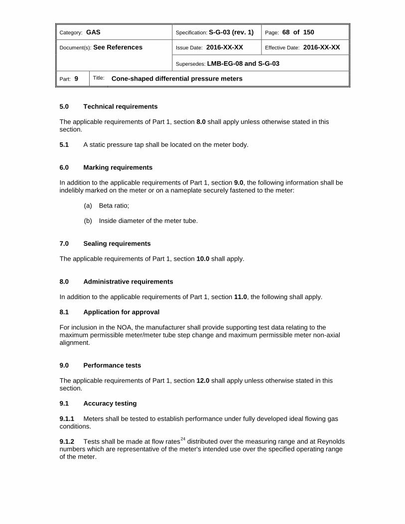
Category: GAS Specification: S-G-03 (rev. 1) Page: 68 of 150
Document(s): See References Issue Date: 2016-XX-XX Effective Date: 2016-XX-XX
Supersedes: LMB-EG-08 and S-G-03
Part: 9 Title: Cone-shaped differential pressure meters
Technical requirements 5.0 The applicable requirements of Part 1, section 8.0 shall apply unless otherwise stated in this section. 5.1 A static pressure tap shall be located on the meter body.
Marking requirements 6.0 In addition to the applicable requirements of Part 1, section 9.0, the following information shall be indelibly marked on the meter or on a nameplate securely fastened to the meter:
(a) Beta ratio;
(b) Inside diameter of the meter tube.
Sealing requirements 7.0 The applicable requirements of Part 1, section 10.0 shall apply.
Administrative requirements 8.0 In addition to the applicable requirements of Part 1, section 11.0, the following shall apply. 8.1 Application for approval For inclusion in the NOA, the manufacturer shall provide supporting test data relating to the maximum permissible meter/meter tube step change and maximum permissible meter non-axial alignment.
Performance tests 9.0 The applicable requirements of Part 1, section 12.0 shall apply unless otherwise stated in this section. 9.1 Accuracy testing 9.1.1 Meters shall be tested to establish performance under fully developed ideal flowing gas conditions. 9.1.2 Tests shall be made at flow rates24 distributed over the measuring range and at Reynolds numbers which are representative of the meter's intended use over the specified operating range of the meter.
Category: GAS Specification: S-G-03 (rev. 1) Page: 69 of 150
Document(s): See References Issue Date: 2016-XX-XX Effective Date: 2016-XX-XX
Supersedes: LMB-EG-08 and S-G-03
Part: 9 Title: Cone-shaped differential pressure meters
9.2 Swirl susceptibility testing The meter shall be tested according to subsection 9.1 and Part 1, subsection 12.5.8.
Category: GAS Specification: S-G-03 (rev. 1) Page: 70 of 150
Document(s): See References Issue Date: 2016-XX-XX Effective Date: 2016-XX-XX
Supersedes: LMB-EG-08 and S-G-03
Part: 10 Title: Mechanical volume conversion devices
Part 10: Mechanical volume conversion devices
Table of contents
Scope ............................................................................................................................... 71 1.0 Terminology .................................................................................................................... 71 2.0 Units ................................................................................................................................. 71 3.0 Metrological requirements ............................................................................................. 71 4.0
4.1 Maximum permissible errors ............................................................................................ 71 Technical requirements ................................................................................................. 72 5.0
5.1 Level indicator ................................................................................................................... 72 5.2 Frequency of integration ................................................................................................... 72 Marking requirements .................................................................................................... 72 6.0
6.1 Integrator .......................................................................................................................... 73 6.2 Temperature and pressure sensing elements .................................................................. 73 Sealing requirements ..................................................................................................... 73 7.0 Administrative requirements ......................................................................................... 73 8.0 Performance tests .......................................................................................................... 74 9.0
9.1 General ............................................................................................................................. 74 9.2 Operating conditions ......................................................................................................... 74 9.3 Flow rate test points ......................................................................................................... 75 9.4 Evaluation tests ................................................................................................................ 75
Category: GAS Specification: S-G-03 (rev. 1) Page: 71 of 150
Document(s): See References Issue Date: 2016-XX-XX Effective Date: 2016-XX-XX
Supersedes: LMB-EG-08 and S-G-03
Part: 10 Title: Mechanical volume conversion devices
Scope 1.0 This part of the Specifications applies to mechanical conversion devices/functions submitted for approval.
Terminology 2.0 Mechanical conversion device or function (dispositif ou fonction de conversion mécanique) Automatic conversion of volume of gas measured at operating conditions to the volume at base temperature or base pressure, or at both, and which may or may not include supercompressibility corrections.25
Units 3.0 The applicable requirements of Part 1, section 6.0 shall apply.
Metrological requirements 4.0 The applicable requirements of Part 1, section 7.0 shall apply unless otherwise stated in this section. 4.1 Maximum permissible errors The following MPEs shall apply (see Part 10, Table 1).
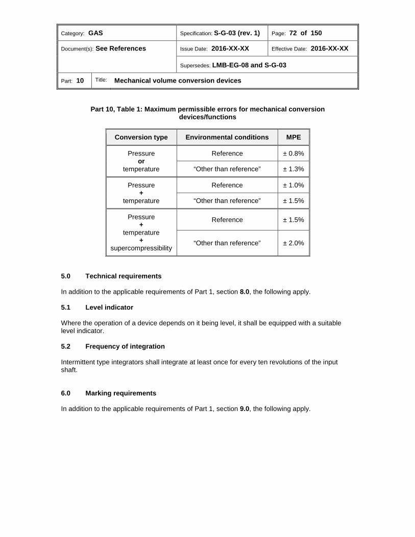
Category: GAS Specification: S-G-03 (rev. 1) Page: 72 of 150
Document(s): See References Issue Date: 2016-XX-XX Effective Date: 2016-XX-XX
Supersedes: LMB-EG-08 and S-G-03
Part: 10 Title: Mechanical volume conversion devices
Part 10, Table 1: Maximum permissible errors for mechanical conversion devices/functions
Conversion type Environmental conditions MPE
Pressure or
temperature
Reference ± 0.8%
“Other than reference” ± 1.3%
Pressure +
temperature
Reference ± 1.0%
“Other than reference” ± 1.5%
Pressure +
temperature +
supercompressibility
Reference ± 1.5%
“Other than reference” ± 2.0%
Technical requirements 5.0 In addition to the applicable requirements of Part 1, section 8.0, the following apply. 5.1 Level indicator Where the operation of a device depends on it being level, it shall be equipped with a suitable level indicator. 5.2 Frequency of integration Intermittent type integrators shall integrate at least once for every ten revolutions of the input shaft.
Marking requirements 6.0 In addition to the applicable requirements of Part 1, section 9.0, the following apply.
Category: GAS Specification: S-G-03 (rev. 1) Page: 73 of 150
Document(s): See References Issue Date: 2016-XX-XX Effective Date: 2016-XX-XX
Supersedes: LMB-EG-08 and S-G-03
Part: 10 Title: Mechanical volume conversion devices
6.1 Integrator 6.1.1 The following information shall be marked on the device or the host meter, where applicable:
(a) Flowing gas temperature range;
(b) Pressure range;
(c) Fixed parameters for supercompressibility factor (e.g. gas relative density, N2 and CO2 content);
(d) Volume per revolution of input drive;
(e) Base temperature;
(f) Base pressure;
(g) Atmospheric pressure;
(h) Non-integral conversion devices shall also be marked with the following:
(i) Maximum speed of rotation of the input drive;
(ii) Direction of rotation of the input drive;
(iii) Input volume per revolution of the input drive.
6.2 Temperature and pressure sensing elements The following information shall be marked on the device or the host meter, where applicable:
(a) Manufacturer's name or registered trade mark;
(b) Type, model or class designation for the elements;
(c) Rated ranges of temperature and pressure.
Sealing requirements 7.0 The applicable requirements of Part 1, section 10.0 shall apply.
Administrative requirements 8.0 The applicable requirements of Part 1, section 11.0 shall apply.
Category: GAS Specification: S-G-03 (rev. 1) Page: 74 of 150
Document(s): See References Issue Date: 2016-XX-XX Effective Date: 2016-XX-XX
Supersedes: LMB-EG-08 and S-G-03
Part: 10 Title: Mechanical volume conversion devices
Performance tests 9.0 The applicable requirements of Part 1, section 12.0 shall apply unless otherwise stated in this section. 9.1 General 9.1.1 Integral mechanical conversion devices shall be installed in a host meter for testing. 9.1.2 Non-integral conversion devices shall be driven by a test rig. 9.2 Operating conditions 9.2.1 Temperature conversion 9.2.1.1 At reference environmental conditions, the flowing gas temperature sensing element shall be held at the minimum temperature marked on the nameplate at 25%, 50% and 75% of the span and at the maximum temperature marked on the nameplate. 9.2.1.2 At “other than reference” environmental conditions, the flowing gas temperature sensing element shall be held at 25% and 75% of the span. 9.2.2 Pressure conversion The flowing gas pressure shall be at 25%, 50%, 75% and 100% of the pressure range, first with increasing pressure and then with decreasing pressure, ensuring that in reaching any test point, the change in pressure is in one direction only. 9.2.3 Temperature and pressure conversion 9.2.3.1 At reference environmental conditions, the following shall apply:
(a) The flowing gas pressure shall be 50% of pressure range with the flowing gas temperature sensing element held at temperatures stated in 9.2.1.1.
(b) The flowing gas temperature sensing element shall be held at a temperature
corresponding to 50% of the span with the flowing gas pressures described in subsection 9.2.2.
(c) The flowing gas pressure shall be 25% and 100% of the pressure range with the
flowing gas temperature sensing element held at minimum and maximum temperature.
9.2.3.2 At “other than reference” environmental conditions, the flowing gas pressure shall be at 25%, 75% and 100% of the maximum pressure with the flowing gas temperature sensing element held at temperatures corresponding to 25% and 75% of the span.

Category: GAS Specification: S-G-03 (rev. 1) Page: 75 of 150
Document(s): See References Issue Date: 2016-XX-XX Effective Date: 2016-XX-XX
Supersedes: LMB-EG-08 and S-G-03
Part: 10 Title: Mechanical volume conversion devices
9.3 Flow rate test points 9.3.1 Integral conversion devices/functions shall be tested at 25% of Qmax. 9.3.2 Non-integral conversion devices/functions shall be tested at the maximum speed of rotation or input frequency specified by the manufacturer. 9.4 Evaluation tests 9.4.1 Accuracy testing
Temperature conversion 9.4.1.1
(a) At reference environmental conditions, tests shall be made at test points according to subsection 9.3 and at operating conditions as stated in 9.2.1.1 (see Part 10, Table 2).
(b) At “other than reference” environmental conditions, tests shall be made at test
points according to subsection 9.3 and at operating conditions as stated in 9.2.1.2 (see Part 10, Table 2).
Part 10, Table 2: Temperature conversion - accuracy testing
Integral or
non-integral Flow rate
Flowing gas temperature (T) (% of span and Tmin or Tmax marked on the nameplate)
Environmental test conditions
Integral 0.25 Qmax
Tmin, 25%, 50%, 75%, Tmax Reference
25% “Other than reference” (low ambient temperature)
75% “Other than reference” (high ambient temperature)
Non-integral
100% of max speed of
rotation or input
frequency
Tmin, 25%, 50%, 75%, Tmax Reference
25% “Other than reference” (low ambient temperature)
75% “Other than reference” (high ambient temperature)
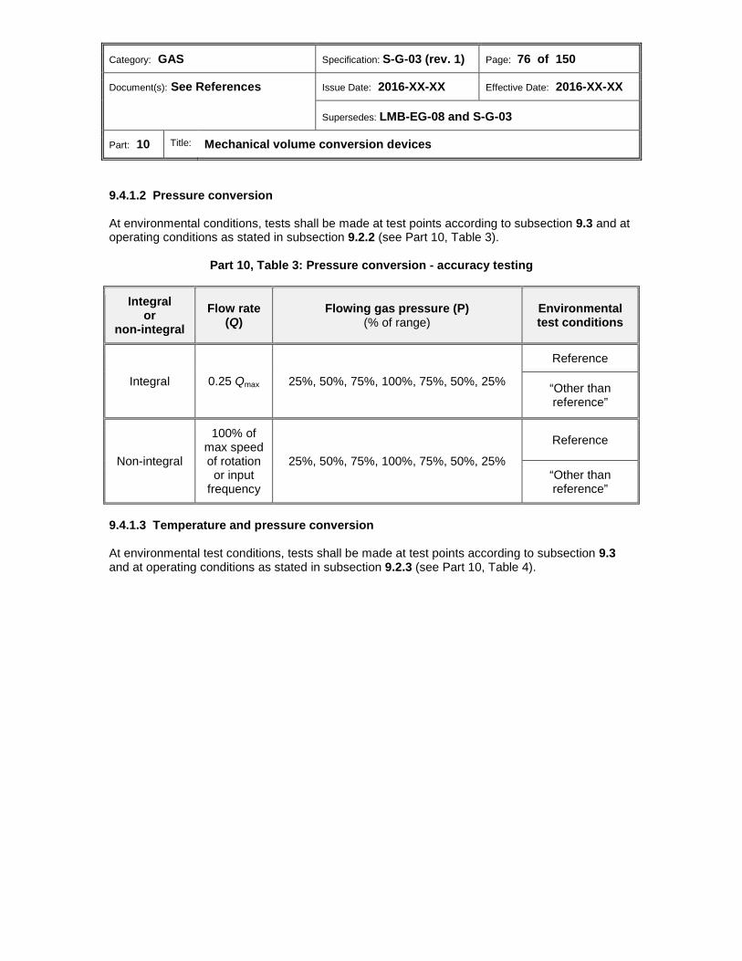
Category: GAS Specification: S-G-03 (rev. 1) Page: 76 of 150
Document(s): See References Issue Date: 2016-XX-XX Effective Date: 2016-XX-XX
Supersedes: LMB-EG-08 and S-G-03
Part: 10 Title: Mechanical volume conversion devices
Pressure conversion 9.4.1.2 At environmental conditions, tests shall be made at test points according to subsection 9.3 and at operating conditions as stated in subsection 9.2.2 (see Part 10, Table 3).
Part 10, Table 3: Pressure conversion - accuracy testing
Integral or
non-integral Flow rate
(Q) Flowing gas pressure (P)
(% of range) Environmental test conditions
Integral 0.25 Qmax 25%, 50%, 75%, 100%, 75%, 50%, 25%
Reference
“Other than reference”
Non-integral
100% of max speed of rotation or input
frequency
25%, 50%, 75%, 100%, 75%, 50%, 25%
Reference
“Other than reference”
Temperature and pressure conversion 9.4.1.3
At environmental test conditions, tests shall be made at test points according to subsection 9.3 and at operating conditions as stated in subsection 9.2.3 (see Part 10, Table 4).

Category: GAS Specification: S-G-03 (rev. 1) Page: 77 of 150
Document(s): See References Issue Date: 2016-XX-XX Effective Date: 2016-XX-XX
Supersedes: LMB-EG-08 and S-G-03
Part: 10 Title: Mechanical volume conversion devices
Part 10, Table 4: Temperature and pressure conversion - accuracy testing
Integral or
non-integral
Flow rate (Q)
Environmental test conditions
Flowing gas temperature (T)
(% of span and Tmin or Tmax marked
on the nameplate)
Flowing gas pressure (P) (% of range)
Integral 0.25 Qmax
Reference
Tmin, 25%, 50%, 75%, Tmax
50%
50% 25%, 50%, 75%, 100%, 75%, 50%, 25%
Tmin, Tmax 25%
100%
“Other than reference” (low ambient temperature)
25%
25%, 50%, 75% “Other than reference”
(high ambient temperature)
75%
Non-integral
100% of max speed of rotation or input
frequency
Reference
Tmin, 25%, 50%, 75%, Tmax
50%
50% 25%, 50%, 75%, 100%, 75%, 50%, 25%
Tmin, Tmax 25%
100%
“Other than reference” (low ambient temperature)
25%
25%, 50%, 75% “Other than reference”
(high ambient temperature)
75%
Category: GAS Specification: S-G-03 (rev. 1) Page: 78 of 150
Document(s): See References Issue Date: 2016-XX-XX Effective Date: 2016-XX-XX
Supersedes: LMB-EG-08 and S-G-03
Part: 10 Title: Mechanical volume conversion devices
9.4.2 Out-of-level tests For non-integral correcting devices not equipped with a level indicator, at least two tests at reference environmental conditions shall be selected from those specified in subsections 9.4.1.1, 9.4.1.2 or 9.4.1.3, or as applicable to determine whether the device remains within tolerance when out of level by five degrees.
Category: GAS Specification: S-G-03 (rev. 1) Page: 79 of 150
Document(s): See References Issue Date: 2016-XX-XX Effective Date: 2016-XX-XX
Supersedes: LMB-EG-08 and S-G-03
Part: 11 Title: Electronic volume conversion devices/functions and flow computers
Part 11: Electronic volume conversion devices/functions and flow computers
Table of contents
Scope ............................................................................................................................... 80 1.0 Terminology .................................................................................................................... 80 2.0 Units ................................................................................................................................. 80 3.0 Metrological requirements ............................................................................................. 80 4.0
4.1 Maximum permissible errors ............................................................................................ 80 Technical requirements ................................................................................................. 82 5.0
5.1 Frequency of sampling ..................................................................................................... 82 5.2 Calculations ...................................................................................................................... 82 5.3 Flow computers ................................................................................................................ 82 Marking requirements .................................................................................................... 82 6.0 Sealing requirements ..................................................................................................... 83 7.0 Administrative requirements ......................................................................................... 83 8.0 Performance tests .......................................................................................................... 84 9.0
9.1 General ............................................................................................................................. 84 9.2 Operating conditions ......................................................................................................... 84 9.3 Flow rate test points ......................................................................................................... 85 9.4 Evaluation test .................................................................................................................. 86

Category: GAS Specification: S-G-03 (rev. 1) Page: 80 of 150
Document(s): See References Issue Date: 2016-XX-XX Effective Date: 2016-XX-XX
Supersedes: LMB-EG-08 and S-G-03
Part: 11 Title: Electronic volume conversion devices/functions and flow computers
Scope 1.0 This part of the Specifications applies to electronic volume conversion (EVC) devices/functions and flow computers submitted for approval.
Terminology 2.0 Configurable parameter (paramètre configurable) Any adjustable or selectable parameter within a configurable device that can have an effect on the accuracy of a device or can significantly increase the potential for fraudulent use of the device and, based on its nature, may need to be updated on an ongoing basis or only during device installation or upon replacement of a component. Electronic volume conversion device or function (dispositif ou fonctions de conversion du volume électronique) Device or function that processes information related to the measurement of natural gas and electronically performs calculations based on the information received. Includes devices such as flow computers for use with orifice meters and volumetric meters and to built-in or associated measuring temperature, pressure, supercompressibility and/or mass conversion devices. Programmable constant (constante programmable) Configurable parameter used in a flow computation which is constant for a given set of operating conditions, but which may be reprogrammed for another set of operating conditions.
Units 3.0 The applicable requirements of Part 1, section 6.0 shall apply.
Metrological requirements 4.0 The applicable requirements of Part 1, section 7.0 shall apply unless otherwise stated in this section. 4.1 Maximum permissible errors The following MPEs shall apply (see Part 11, Table 1).
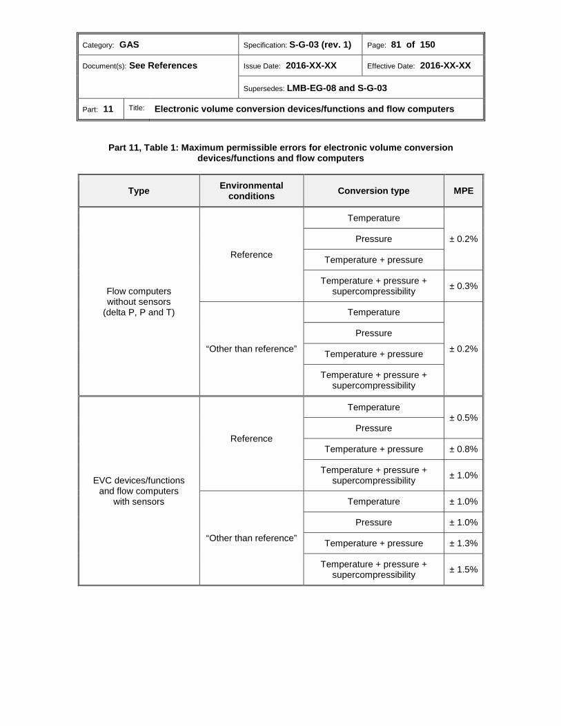
Category: GAS Specification: S-G-03 (rev. 1) Page: 81 of 150
Document(s): See References Issue Date: 2016-XX-XX Effective Date: 2016-XX-XX
Supersedes: LMB-EG-08 and S-G-03
Part: 11 Title: Electronic volume conversion devices/functions and flow computers
Part 11, Table 1: Maximum permissible errors for electronic volume conversion devices/functions and flow computers
Type Environmental conditions Conversion type MPE
Flow computers without sensors
(delta P, P and T)
Reference
Temperature
± 0.2% Pressure
Temperature + pressure
Temperature + pressure + supercompressibility ± 0.3%
“Other than reference”
Temperature
± 0.2% Pressure
Temperature + pressure
Temperature + pressure + supercompressibility
EVC devices/functions and flow computers
with sensors
Reference
Temperature ± 0.5%
Pressure
Temperature + pressure ± 0.8%
Temperature + pressure + supercompressibility ± 1.0%
“Other than reference”
Temperature ± 1.0%
Pressure ± 1.0%
Temperature + pressure ± 1.3%
Temperature + pressure + supercompressibility ± 1.5%
Category: GAS Specification: S-G-03 (rev. 1) Page: 82 of 150
Document(s): See References Issue Date: 2016-XX-XX Effective Date: 2016-XX-XX
Supersedes: LMB-EG-08 and S-G-03
Part: 11 Title: Electronic volume conversion devices/functions and flow computers
Technical requirements 5.0 In addition to the applicable requirements of Part 1, section 8.0, the following apply. 5.1 Frequency of sampling The device shall be capable of sampling applicable inputs and calculating the measurement units at least every 30 seconds. Where no input is received from the primary meter, no sampling need take place. 5.2 Calculations 5.2.1 Calculations of accumulated units of measurement shall be according to appropriate flow equations and other provisions of the Electricity and Gas Inspection Act and Regulations. 5.2.2 Calculations by flow computers intended for use with orifice meters shall be according to the provisions of the latest edition of AGA Report No. 3, Orifice Metering of Natural Gas and Other Related Hydrocarbon Fluids. 5.3 Flow computers 5.3.1 General The non-measured data necessary for conversions and correction shall be present in the flow computer before a measurement is made. 5.3.2 Multi-channel flow computers 5.3.2.1 Where a flow computer is designed to process information from more than one meter, it shall be capable of accepting the required meter-specific inputs separately for each meter. 5.3.2.2 The inputs for base pressure, base temperature, atmospheric pressure, relative density and mol percent content of the gas components applicable to the calculation method applied or calorific power may be common for all meters, subject to the following requirements:
(a) Common inputs for relative density and mol percent content of the gas components applicable to the calculation method applied or calorific power shall be limited to use with groups which are fed from a common supply of gas; and
(b) Common inputs for atmospheric pressure shall be limited to use with groups of
meters which are such that the requirements of the Electricity and Gas Inspection Regulations will be complied with.
Marking requirements 6.0 In addition to the applicable requirements of Part 1, section 9.0, the following apply.

Category: GAS Specification: S-G-03 (rev. 1) Page: 83 of 150
Document(s): See References Issue Date: 2016-XX-XX Effective Date: 2016-XX-XX
Supersedes: LMB-EG-08 and S-G-03
Part: 11 Title: Electronic volume conversion devices/functions and flow computers
6.1 The following information shall appear on the nameplate or be accessible via the device’s electronic display or output to an external device, through provisions for printing this information or other method:
(a) Minimum and maximum ranges of measurement parameters for all sources which the device may be configured to measure (minimum ranges are not required where the configuration application does not permit a configuration below the minimum);
(b) Configured range of measurement parameters for all sources which the device is
configured to measure;
(c) Type and range of each analog input and/or output signal;
(d) Protocol/interface for digital input and/or output;
(e) Values of all fixed constants or quantities used in the calculation of measurement units;
(f) Values of all live quantities used in the calculation of measurement units;
(g) Value of each of the variables in the equation used to determine measurement
units. 6.2 Where codes are used, a legend shall appear on the device. 6.3 Where switch settings, jumper locations or other means used to identify the value of a fixed constant is permitted in the NOA, the approval shall identify each fixed constant for which the method is applicable and the configuration or the other means for each value of each fixed constant. 6.4 The connection terminals shall be identified by markings on the device or by a table or a schematic diagram permanently affixed to the device. Where a metering device is designed to accept a non-interchangeable cable connector, the connection terminal for that connector shall be exempted from this requirement.
Sealing requirements 7.0 The applicable requirements of Part 1, section 10.0 shall apply.
Administrative requirements 8.0 The applicable requirements of Part 1, section 11.0 shall apply.
Category: GAS Specification: S-G-03 (rev. 1) Page: 84 of 150
Document(s): See References Issue Date: 2016-XX-XX Effective Date: 2016-XX-XX
Supersedes: LMB-EG-08 and S-G-03
Part: 11 Title: Electronic volume conversion devices/functions and flow computers
Performance tests 9.0 The applicable requirements of Part 1, section 12.0 shall apply unless otherwise stated in this section. 9.1 General 9.1.1 Electronic volume conversion devices/functions and/or flow computers (devices with sensors) Devices with transducers shall be attached to the host meter for testing. 9.2 Operating conditions 9.2.1 Operating conditions for flow computers (devices without sensors (Delta P, P and T)) 9.2.1.1 At reference environmental conditions, the device shall be tested with:
(a) all inputs and programmable constants at their minimum, median and maximum values;26
(b) each input and programmable constant in turn at its maximum and minimum
values27 with the remaining parameters at their median values. 9.2.1.2 At “other than reference” environmental conditions, all inputs and programmable constants shall be at their median values. 9.2.2 Operating conditions for electronic volume correcting devices/functions and/or flow computers (devices with sensors)
Temperature conversion 9.2.2.1
(a) At reference environmental conditions, the flowing gas temperature sensing element shall be held at the minimum temperature marked on the nameplate at 25%, 50% and 75% of the span, and at the maximum temperature marked on the nameplate.
(b) At “other than reference” environmental conditions, the flowing gas temperature
sensing element shall be held at temperatures corresponding to 25% and 75% of the span.
Pressure conversion 9.2.2.2
The flowing gas pressure shall be at 25%, 50%, 75% and 100% of the pressure range, first with increasing pressure and then with decreasing pressure, ensuring that in reaching any test point, the change in pressure is in one direction only.

Category: GAS Specification: S-G-03 (rev. 1) Page: 85 of 150
Document(s): See References Issue Date: 2016-XX-XX Effective Date: 2016-XX-XX
Supersedes: LMB-EG-08 and S-G-03
Part: 11 Title: Electronic volume conversion devices/functions and flow computers
Temperature and pressure conversion 9.2.2.3
(a) For inputs corresponding to a linear meter, the following shall apply at reference environmental conditions:
(i) The flowing gas pressure shall be 50% of the pressure range with the
flowing gas temperature sensing element held at the temperatures stated in 9.2.2.1(a).
(ii) The flowing gas temperature sensing element shall be held at a temperature
corresponding to 50% of the span with the flowing gas pressures described in subsection 9.2.2.2.
(iii) The flowing gas pressure shall be 25% of the pressure range and the
flowing gas temperature sensing element held at the minimum and maximum temperature marked on the nameplate.
(iv) The flowing gas pressure shall be 100% of the pressure range and the
flowing gas temperature sensing element held at the minimum and maximum temperature marked on the nameplate.
(b) For inputs corresponding to a linear meter at “other than reference” environmental
conditions, the flowing gas pressure shall be at 25%, 50% and 75% of the maximum pressure with the flowing gas temperature sensing element held at temperatures corresponding to 25% and 75% of the span.
(c) For inputs corresponding to a differential pressure, the following shall apply at
reference environmental conditions:
(i) Operating conditions as specified in 9.2.2.3(a) (i) and (ii) with a differential pressure of 50%.
(ii) Operating conditions as specified in 9.2.2.3(a) (iii) with a differential
pressure of 10% and 100%.
(iii) Operating conditions as specified in 9.2.2.3(a) (iv) with a differential pressure of 10% and 100%.
(iv) The flowing gas pressure and temperature shall be held at 50% of their
respective ranges with the differential pressures at 10%, 25%, 50%, 75% and 100% of the differential pressure range, first with increasing differential pressure and then with decreasing differential pressure.
9.3 Flow rate test points 9.3.1 Integral conversion devices/functions shall be tested at 10% of Qmax and Qmax. 9.3.2 Non-integral conversion devices/functions shall be tested at 10% and at maximum speed of rotation or input frequency specified by the manufacturer.
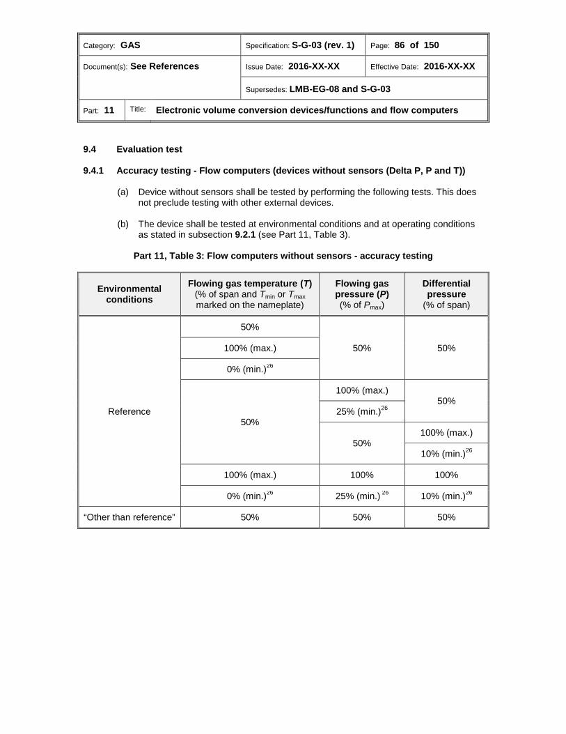
Category: GAS Specification: S-G-03 (rev. 1) Page: 86 of 150
Document(s): See References Issue Date: 2016-XX-XX Effective Date: 2016-XX-XX
Supersedes: LMB-EG-08 and S-G-03
Part: 11 Title: Electronic volume conversion devices/functions and flow computers
9.4 Evaluation test 9.4.1 Accuracy testing - Flow computers (devices without sensors (Delta P, P and T))
(a) Device without sensors shall be tested by performing the following tests. This does not preclude testing with other external devices.
(b) The device shall be tested at environmental conditions and at operating conditions
as stated in subsection 9.2.1 (see Part 11, Table 3).
Part 11, Table 3: Flow computers without sensors - accuracy testing
Environmental conditions
Flowing gas temperature (T) (% of span and Tmin or Tmax marked on the nameplate)
Flowing gas pressure (P) (% of Pmax)
Differential pressure
(% of span)
Reference
50%
50% 50% 100% (max.)
0% (min.)26
50%
100% (max.) 50%
25% (min.)26
50% 100% (max.)
10% (min.)26
100% (max.) 100% 100%
0% (min.)26 25% (min.) 26 10% (min.)26
“Other than reference” 50% 50% 50%

Category: GAS Specification: S-G-03 (rev. 1) Page: 87 of 150
Document(s): See References Issue Date: 2016-XX-XX Effective Date: 2016-XX-XX
Supersedes: LMB-EG-08 and S-G-03
Part: 11 Title: Electronic volume conversion devices/functions and flow computers
9.4.2 Accuracy testing of electronic volume conversion devices/functions and/or flow computers (devices with sensors)
Temperature conversion 9.4.2.1
(a) Devices with integral sensors shall be tested by performing the following tests. The device can be an integral or non-integral device to a host gas meter. This does not preclude additional testing with other included devices.
(b) At environmental conditions, tests shall be made at test points according to
subsection 9.3 and at operating conditions as stated in subsection 9.2.2.1 (see Part 11, Table 4).
Part 11, Table 4: Accuracy testing of electronic volume conversion devices/functions
and/or flow computers (devices with sensors) – temperature conversion
Integral or
non-integral Flow rate
(Q) Environmental
conditions Flowing gas temperature (T)
(% of span and Tmin or Tmax marked on the nameplate)
Integral 0.10 Qmax, Qmax
Reference Tmin, 25%, 50%, 75%, Tmax
“Other than reference” (low ambient temperature) 25%
“Other than reference” (high ambient temperature) 75%
Non-integral
10% and 100% of max speed of rotation or input
frequency
Reference Tmin, 25%, 5%0, 75%, Tmax
“Other than reference” (low ambient temperature) 25%
“Other than reference” (high ambient temperature) 75%
Pressure conversion 9.4.2.2
(a) The device with integral sensors shall be tested. The device can be an integral or
non-integral device to a host gas meter.
(b) At environmental conditions, tests shall be made at test points according to subsection 9.3 and at operating conditions as stated in subsection 9.2.2.2 (see Part 11, Table 5).
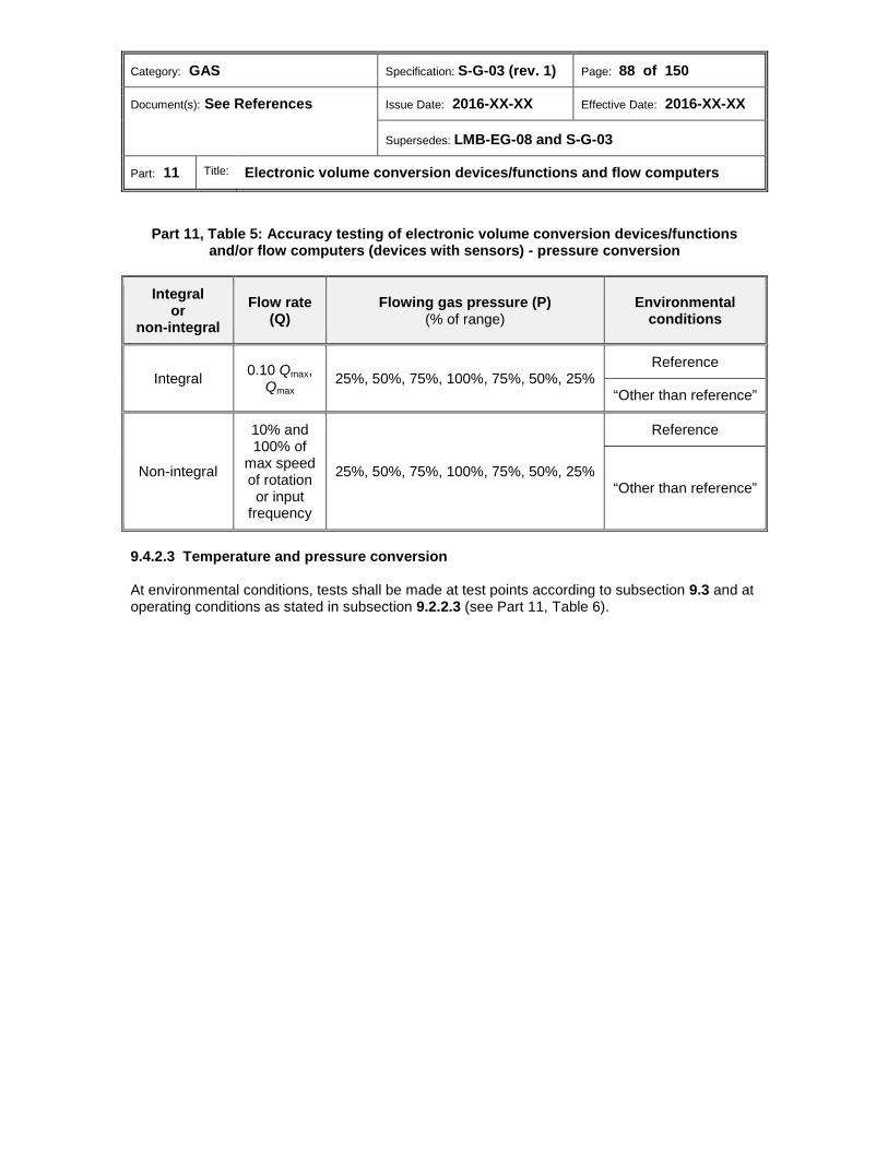
Category: GAS Specification: S-G-03 (rev. 1) Page: 88 of 150
Document(s): See References Issue Date: 2016-XX-XX Effective Date: 2016-XX-XX
Supersedes: LMB-EG-08 and S-G-03
Part: 11 Title: Electronic volume conversion devices/functions and flow computers
Part 11, Table 5: Accuracy testing of electronic volume conversion devices/functions and/or flow computers (devices with sensors) - pressure conversion
Integral or
non-integral Flow rate
(Q) Flowing gas pressure (P)
(% of range) Environmental
conditions
Integral 0.10 Qmax, Qmax
25%, 50%, 75%, 100%, 75%, 50%, 25% Reference
“Other than reference”
Non-integral
10% and 100% of
max speed of rotation or input
frequency
25%, 50%, 75%, 100%, 75%, 50%, 25%
Reference
“Other than reference”
Temperature and pressure conversion 9.4.2.3
At environmental conditions, tests shall be made at test points according to subsection 9.3 and at operating conditions as stated in subsection 9.2.2.3 (see Part 11, Table 6).
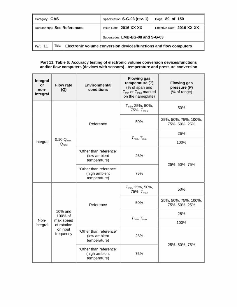
Category: GAS Specification: S-G-03 (rev. 1) Page: 89 of 150
Document(s): See References Issue Date: 2016-XX-XX Effective Date: 2016-XX-XX
Supersedes: LMB-EG-08 and S-G-03
Part: 11 Title: Electronic volume conversion devices/functions and flow computers
Part 11, Table 6: Accuracy testing of electronic volume conversion devices/functions and/or flow computers (devices with sensors) - temperature and pressure conversion
Integral or
non-integral
Flow rate (Q)
Environmental conditions
Flowing gas temperature (T) (% of span and
Tmin or Tmax marked on the nameplate)
Flowing gas pressure (P) (% of range)
Integral 0.10 Qmax, Qmax
Reference
Tmin, 25%, 50%, 75%, Tmax
50%
50% 25%, 50%, 75%, 100%, 75%, 50%, 25%
Tmin, Tmax 25%
100%
“Other than reference” (low ambient temperature)
25%
25%, 50%, 75% “Other than reference”
(high ambient temperature)
75%
Non-integral
10% and 100% of
max speed of rotation or input
frequency
Reference
Tmin, 25%, 50%, 75%, Tmax
50%
50% 25%, 50%, 75%, 100%, 75%, 50%, 25%
Tmin, Tmax 25%
100%
“Other than reference” (low ambient temperature)
25%
25%, 50%, 75% “Other than reference”
(high ambient temperature)
75%
Category: GAS Specification: S-G-03 (rev. 1) Page: 90 of 150
Document(s): See References Issue Date: 2016-XX-XX Effective Date: 2016-XX-XX
Supersedes: LMB-EG-08 and S-G-03
Part: 12 Title: Electrical pulse devices/functions
Part 12: Electrical pulse devices/functions
Table of contents
Scope ............................................................................................................................... 91 1.0 Units ................................................................................................................................. 91 2.0 Metrological requirements ............................................................................................. 91 3.0
3.1 Maximum permissible error .............................................................................................. 91 Technical requirements ................................................................................................. 91 4.0 Marking requirements .................................................................................................... 91 5.0
5.1 Pulse generators............................................................................................................... 91 5.2 Relays and signal amplifiers ............................................................................................. 92 5.3 Pulse receivers ................................................................................................................. 92 5.4 Automatic meter reading devices ..................................................................................... 92 Sealing requirements ..................................................................................................... 93 6.0 Administrative requirements ......................................................................................... 93 7.0 Performance tests .......................................................................................................... 93 8.0
8.1 Evaluation tests ................................................................................................................ 93

Category: GAS Specification: S-G-03 (rev. 1) Page: 91 of 150
Document(s): See References Issue Date: 2016-XX-XX Effective Date: 2016-XX-XX
Supersedes: LMB-EG-08 and S-G-03
Part: 12 Title: Electrical pulse devices/functions
Scope 1.0 This part of the Specifications applies to pulse generators/functions and associated pulse transmitting and receiving devices submitted for approval.
Units 2.0 The applicable requirements of Part 1, section 6.0 shall apply.
Metrological requirements 3.0 The applicable requirements of Part 1, section 7.0 shall apply unless otherwise stated in this section. 3.1 Maximum permissible error The MPE shall not exceed ± 0.05% at any point within the range for which approval is sought.
Technical requirements 4.0 The applicable requirements of Part 1, section 8.0 shall apply.
Marking requirements 5.0 In addition to the applicable requirements of Part 1, section 9.0, the following apply. 5.1 Pulse generators 5.1.1 Non-integral pulse generators 5.1.1.1 Where a pulse generator is a separate entity which can be attached to an approved gas meter or ancillary device, the following information shall be marked on a nameplate attached to the pulse generator:
(a) Number of pulses corresponding to one unit of input to the generator;28
(b) Maximum frequency of input;
(c) Type and amplitude of output signal or contact rating (e.g. “form C” or “form A”).
Category: GAS Specification: S-G-03 (rev. 1) Page: 92 of 150
Document(s): See References Issue Date: 2016-XX-XX Effective Date: 2016-XX-XX
Supersedes: LMB-EG-08 and S-G-03
Part: 12 Title: Electrical pulse devices/functions
5.1.2 Integral pulse generators/functions 5.1.2.1 Where a gas meter or an ancillary device incorporates a pulse generator/function, the following information shall be marked on a nameplate mounted on the host meter/device:
(a) The number of pulses corresponding to a unit of measured quantity or the number of measured units corresponding to one output pulse;
(b) Type and amplitude of output signal, or contact rating (e.g. “form C” or “form A”);
(c) Departmental approval number of the meter/device with the pulse generator.
5.2 Relays and signal amplifiers The following information shall be marked on a nameplate attached to the device:
(a) Type of input and output signals;
(b) Maximum voltage and frequency of input signal, and of output signal for amplifiers;
(c) Minimum input voltage;
(d) Connection diagram (does not need to be readily visible). 5.3 Pulse receivers 5.3.1 Non-integral pulse receivers shall be marked with the following information on a nameplate attached to them:
(a) Type of input signal;
(b) Minimum input voltage;
(c) Maximum voltage and frequency of input signal;
(d) The number of pulses corresponding to a unit of measured quantity or the number of measured units corresponding to one input pulse;
(e) Connection diagram (does not need to be readily visible).
5.3.2 Devices equipped with integral pulse receivers shall be marked with the information required in 5.3.1 on a nameplate attached to the device or made accessible through other means. 5.4 Automatic meter reading devices Automatic meter reading (AMR) devices shall have the applicable information of this section marked on the nameplate or displayed where a display of the marking is permitted.
Category: GAS Specification: S-G-03 (rev. 1) Page: 93 of 150
Document(s): See References Issue Date: 2016-XX-XX Effective Date: 2016-XX-XX
Supersedes: LMB-EG-08 and S-G-03
Part: 12 Title: Electrical pulse devices/functions
Sealing requirements 6.0 The applicable requirements of Part 1, section 10.0 shall apply.
Administrative requirements 7.0 The applicable requirements of Part 1, section 11.0 shall apply.
Performance tests 8.0 The applicable requirements of Part 1, section 12.0 shall apply unless otherwise stated in this section. 8.1 Evaluation tests 8.1.1 The applicant shall conduct the following tests for the pulse input or output or both if applicable, with the ambient temperature maintained at the reference and “other than reference” temperatures:
(a) Tests at the maximum pulse rate specified by the manufacturer;
(b) Tests at the minimum level of input signal voltage to relays, amplifiers and pulse receivers.
8.1.2 The duration of all tests shall be a sufficient to ensure that the accumulated pulses can be determined with a resolution of at least 0.01%. 8.1.3 Where the signal is transmitted or received as a digital representation of an accumulated value, the requirements of 8.1.1 and 8.1.2 shall apply.
Category: GAS Specification: S-G-03 (rev. 1) Page: 94 of 150
Document(s): See References Issue Date: 2016-XX-XX Effective Date: 2016-XX-XX
Supersedes: LMB-EG-08 and S-G-03
Part: 13 Title: Indicating devices
Part 13: Indicating devices
Table of contents
Scope ............................................................................................................................... 95 1.0 Units ................................................................................................................................. 95 2.0 Metrological requirements ............................................................................................. 95 3.0
3.1 Mechanical indicating devices .......................................................................................... 95 3.2 Electronic indicating devices ............................................................................................ 95 Technical requirements ................................................................................................. 95 4.0
4.1 Capacity ............................................................................................................................ 96 4.2 Legibility ............................................................................................................................ 96 4.3 Mechanical indicating devices .......................................................................................... 96 4.4 Electronic indicating devices ............................................................................................ 99 Marking requirements .................................................................................................... 99 5.0 Sealing requirements ................................................................................................... 100 6.0 Administrative requirements ....................................................................................... 100 7.0 Performance tests ........................................................................................................ 100 8.0

Category: GAS Specification: S-G-03 (rev. 1) Page: 95 of 150
Document(s): See References Issue Date: 2016-XX-XX Effective Date: 2016-XX-XX
Supersedes: LMB-EG-08 and S-G-03
Part: 13 Title: Indicating devices
Scope 1.0 This part of the Specifications applies to indicating devices used with gas meters or ancillary devices submitted for approval. The indicating devices may be integral or non-integral mechanical, electro-mechanical or electronic.
Units 2.0 The applicable requirements of Part 1, section 6.0 shall apply.
Metrological requirements 3.0 The applicable requirements of Part 1, section 7.0 shall apply unless otherwise stated in this section. 3.1 Mechanical indicating devices 3.1.1 Mechanical indicating device gear ratios between all dials or drums shall be correct and in agreement with the intended values. 3.1.2 Proving and test provision (dial or drum) capacities, where present, shall be correct as marked on the faceplate of the mechanical indicating device. 3.1.3 The overall gear ratio of mechanical indicating devices from the input shaft to the lowest reading dial or drum shall be correct for use on the meter. 3.1.4 Mechanical indicating devices shall function as intended at any ambient temperature within the range set out in Part 1, subsection 12.2.2 (gears shall mesh and shall not bind). 3.2 Electronic indicating devices 3.2.1 The following requirements shall be met at reference and “other than reference” environmental conditions:
(a) Electronic indicating device input parameters and displayed numerals shall be correct and in agreement with the intended values.
(b) The capacity of proving and test provisions, where present, shall be correct as
marked.
(c) The operation and readability of electronic indicating devices shall not be affected by variations in temperature.
Technical requirements 4.0 In addition to the applicable requirements of Part 1, section 8.0, the following apply.

Category: GAS Specification: S-G-03 (rev. 1) Page: 96 of 150
Document(s): See References Issue Date: 2016-XX-XX Effective Date: 2016-XX-XX
Supersedes: LMB-EG-08 and S-G-03
Part: 13 Title: Indicating devices
4.1 Capacity A cumulative, non-resettable indicating device, whether corrected or uncorrected, shall be so designed that the cumulative indication of the measurement units will not repeat when the host meter operates continuously at its rated or maximum capacity for a period of 90 days, unless stated otherwise in the subsequent sections of these specifications. 4.2 Legibility 4.2.1 The indicating device face and markings thereon shall be of contrasting colours to provide for ease of reading. 4.2.1.1 All markings shall be indelible and shall not be adversely affected by environmental conditions. 4.2.1.2 The size of letters and numerals shall be such that they are clearly legible. 4.3 Mechanical indicating devices 4.3.1 Pointer type mechanical indicating devices Pointer type mechanical indicating devices shall meet the following requirements:
(a) The minimum diameter of clock dial circles shall be 10 mm;
(b) Each dial shall be divided into 10 equal and clearly numbered divisions;
(c) The dial centres shall be located so as to avoid any possibility of ambiguity in reading;
(d) Each dial shall be marked to indicate the number of measured units per revolution
of the pointer;
(e) The dials shall be distinctly separated from each other;
(f) The indicating device gearing shall be such that a complete revolution of any pointer shall cause the adjacent pointer on the left to advance one division;
(g) There shall be no overall multiplier indicated on the indicating device.
Category: GAS Specification: S-G-03 (rev. 1) Page: 97 of 150
Document(s): See References Issue Date: 2016-XX-XX Effective Date: 2016-XX-XX
Supersedes: LMB-EG-08 and S-G-03
Part: 13 Title: Indicating devices
4.3.2 Drum type mechanical indicating devices Drum type mechanical indicating devices shall meet the following requirements:
(a) The digits of the counter shall be in a straight horizontal line and easily visible through one or more cut-outs in the indicating device face;
(b) The arrangement of the counter drums and the cut-out(s) on the indicating device
face shall be such that, with the exception of the fastest rotating drum, only one digit per drum is in full view at all times except when a drum is advancing from one position to another;
(c) The duration of this change period shall not exceed the time required for the fastest-
rotating drum to make one-tenth of a revolution;
(d) Where the last digit shown on a drum type mechanical indicating device represents a multiple of applicable units of measurement, there shall be one of the following:
(i) A number of zeros marked on the indicating device face immediately to the
right of the last digit, and in line with it, so that the reading of the indicating device with the additional zeros is in applicable units; or
(ii) An inscription below the drum digits on the indicating device face to show
the applicable multiplier, such as "Reading X l00 = m3". The multiplier shall be an integral power of 10.
Category: GAS Specification: S-G-03 (rev. 1) Page: 98 of 150
Document(s): See References Issue Date: 2016-XX-XX Effective Date: 2016-XX-XX
Supersedes: LMB-EG-08 and S-G-03
Part: 13 Title: Indicating devices
4.3.3 Proving provisions for mechanical indicating devices Mechanical indicating devices shall be equipped with one of the following to facilitate proving and testing:
(a) A proving dial;
(b) A proving drum that meets the following requirements:
(i) The proving drum shall be divided into 10 equal numbered divisions;
(ii) The diameter of the proving drum in relation to the size of the cut-out in the register face shall be such that for any rotational position of the drum there is at least one numbered division in full view;
(iii) There shall be a reference mark or marks designed in a manner to reduce or
eliminate reading errors caused by parallax;
(iv) The volume per revolution of the proving drum shall be marked on the face of the indicating device in the vicinity of the proving drum;
(v) The proving drum division markings and the size and location of the
reference mark shall be such that the position of the drum with respect to the reference mark can be accurately determined;
(vi) Where an indicating device is an integral component of a meter, the
measured quantity per revolution of the proving drum shall be such that the proving drum makes at least one revolution every two minutes at Qmax.
(c) A proving dial and a test dial that meet the following requirements:
(i) They shall not be in the same geometric line as the reading dials;
(ii) They shall have a minimum of 10 equally spaced divisions, each division
shall have at least five equally spaced subdivisions and arrows shall show the direction of rotation of the pointers;
(iii) The quantity per revolution of the associated pointer shall be clearly marked;
(iv) No numbers shall appear on the divisions;
(v) Where an indicating device is an integral component of a meter, the
measured quantity per revolution of the proving pointer shall be such that the proving pointer makes at least one revolution every two minutes at Qmax.
Category: GAS Specification: S-G-03 (rev. 1) Page: 99 of 150
Document(s): See References Issue Date: 2016-XX-XX Effective Date: 2016-XX-XX
Supersedes: LMB-EG-08 and S-G-03
Part: 13 Title: Indicating devices
4.3.4 Gas meters with built-in correcting provisions Where mechanical indicating devices are employed on meters with built-in correcting provisions, both the corrected and uncorrected indicating devices shall meet the requirement set out in 4.3.3(c), (ii). 4.4 Electronic indicating devices 4.4.1 The operation and readability of electronic indicating devices shall be suitable for use under the variety of environmental conditions which may be encountered in the intended operation, such as temperature, bright light, humidity, etc. 4.4.2 Where one electronic indicating device is used to indicate several different quantities, the following requirements shall be met:
(a) The quantity and the direction of bi-directional measurement shall be indicated;
(b) When not controlled by the operator, the minimum indication time shall be six seconds;
(c) The units associated with the registration and applicable multiplier, if other than
unity, shall be indicated by use of one of the following:
(i) Abbreviations accepted by MC;
(ii) A code (an explanation of the codes shall be available without the use of specialized equipment); or
(iii) Other methods which clearly identify the units and applicable multiplier,
without the use of specialized equipment. 4.4.3 Where an electronic indicating device is designed for use with a host meter which has no other indicating device conforming to the requirements of subsection 4.3.3, the electronic indicating device shall incorporate provisions for proving the meter with sufficient resolution so that the time required to conduct the test is no more than two minutes at Qmax.
Marking requirements 5.0 The applicable requirements of Part 1, section 9.0 shall apply unless otherwise stated in this section. 5.1 Indicating devices forming an integral part of a meter shall be exempt from the requirements set out in Part 1, section 9.0.

Category: GAS Specification: S-G-03 (rev. 1) Page: 100 of 150
Document(s): See References Issue Date: 2016-XX-XX Effective Date: 2016-XX-XX
Supersedes: LMB-EG-08 and S-G-03
Part: 13 Title: Indicating devices
5.2 Indicating devices which are an integral component of the host meter shall bear an indelible marking of the manufacturer's part number, which shall be unique for each model of indicating device.29 5.3 Where an indicating device is not intended to display more than one quantity, the units or symbol being indicated shall be prominently marked or indicated on or adjacent to the indicating device face.
Sealing requirements 6.0 The applicable requirements of Part 1, section 10.0 shall apply.
Administrative requirements 7.0 The applicable requirements of Part 1, section 11.0 shall apply.
Performance tests 8.0 The applicable requirements of Part 1, section 12.0 shall apply.
Category: GAS Specification: S-G-03 (rev. 1) Page: 101 of 150
Document(s): See References Issue Date: 2016-XX-XX Effective Date: 2016-XX-XX
Supersedes: LMB-EG-08 and S-G-03
Part: 14 Title: Gas chromatographs
Part 14: Gas chromatographs
Table of contents
Scope ............................................................................................................................. 102 1.0 Terminology .................................................................................................................. 102 2.0 Units ............................................................................................................................... 102 3.0 Metrological requirements ........................................................................................... 102 4.0
4.1 Maximum permissible error ............................................................................................ 102 4.2 Repeatability ................................................................................................................... 103 Technical requirements ............................................................................................... 103 5.0
5.1 Calculations .................................................................................................................... 103 Marking requirements .................................................................................................. 103 6.0 Sealing requirements ................................................................................................... 103 7.0 Administrative requirements ....................................................................................... 104 8.0 Performance tests ........................................................................................................ 104 9.0

Category: GAS Specification: S-G-03 (rev. 1) Page: 102 of 150
Document(s): See References Issue Date: 2016-XX-XX Effective Date: 2016-XX-XX
Supersedes: LMB-EG-08 and S-G-03
Part: 14 Title: Gas chromatographs
Scope 1.0 This part of the Specifications applies to any device or system which calculates the energy density or relative density, or measures the molecular composition of a gas sample by identifying the component concentrations of the gas.
Terminology 2.0 Ancillary output signal (signal de sortie auxiliaire) Output signal that attempts to supply information to an ancillary device other than a dedicated recorder intended for use with the calorimeter. Energy density (énergie volumique) Number of energy units per unit of volume at a certain temperature and pressure. Energy density is formally known as calorific power or heating value. It is expressed in British thermal units per cubic foot (BTU/ft3) in the imperial system or in MJ/m3 in the International System of Units (SI). Laboratory gas chromatograph (chromatographe en phase gazeuse de laboratoire) Gas chromatograph located at a test facility and used to analyze gas samples taken in situ. Online gas chromatograph (chromatographe en phase gazeuse en ligne) Gas chromatograph whose sampling system is directly connected to the gas network and that transmits the energy density, relative density or molecular composition of a gas sample to a correction device or one or more flow computers.
Units 3.0 The applicable requirements of Part 1, section 6.0 shall apply.
Metrological requirements 4.0 The applicable requirements of Part 1, section 7.0 shall apply unless otherwise stated in this section. 4.1 Maximum permissible error 4.1.1 Where a device provides energy density and/or relative density as a direct output, with or without providing relative concentrations of gas constituents, the energy density error shall not exceed ± 0.1 MJ/m3, and the relative density error shall not exceed ± 0.5%.
Category: GAS Specification: S-G-03 (rev. 1) Page: 103 of 150
Document(s): See References Issue Date: 2016-XX-XX Effective Date: 2016-XX-XX
Supersedes: LMB-EG-08 and S-G-03
Part: 14 Title: Gas chromatographs
4.1.2 Where a device is intended to detect concentrations of only nitrogen and carbon dioxide, the error shall not exceed ± 0.1 mol %. 4.2 Repeatability The repeatability of error shall be ± 0.3 mol % for constituents over 25 mol %.
Technical requirements 5.0 In addition to the applicable requirements of Part 1, section 8.0, the following apply. 5.1 Calculations The true energy density and relative density of the sample gas shall be calculated using the true relative concentrations of all components of the sample gas as established in accordance with the following Gas Processors Association standards: GPA 2172—Calculation of Gross Heating Value, Relative Density and Compressibility Factor for Natural Gas Mixtures from Compositional Analysis, and GPA 2145—Table of Physical Properties for Hydrocarbons and Other Compounds of Interest to the Natural Industry.
Marking requirements 6.0 6.1 In addition to the applicable requirements of Part 1, section 9.0, the following information shall be marked on the nameplate or be capable of being displayed by the device:
(a) Ancillary output signal (if provided);30
(i) Type and range of analogue output signal;
(ii) Protocol/interface for digital output.
(b) The recognized standard used by the device in calculating the energy value of the gas composition; and
(c) Where a device provides an indication of energy in the imperial system:
(i) The particular British thermal unit displayed (e.g. BTU(60.5), BTU(IT), BTU(59));
(ii) The base temperature and pressure used in establishing the energy density.
Sealing requirements 7.0 The applicable requirements of Part 1, section 10.0 shall apply unless otherwise stated in this section. 7.1 Laboratory gas chromatographs shall be exempted from the sealing provisions.
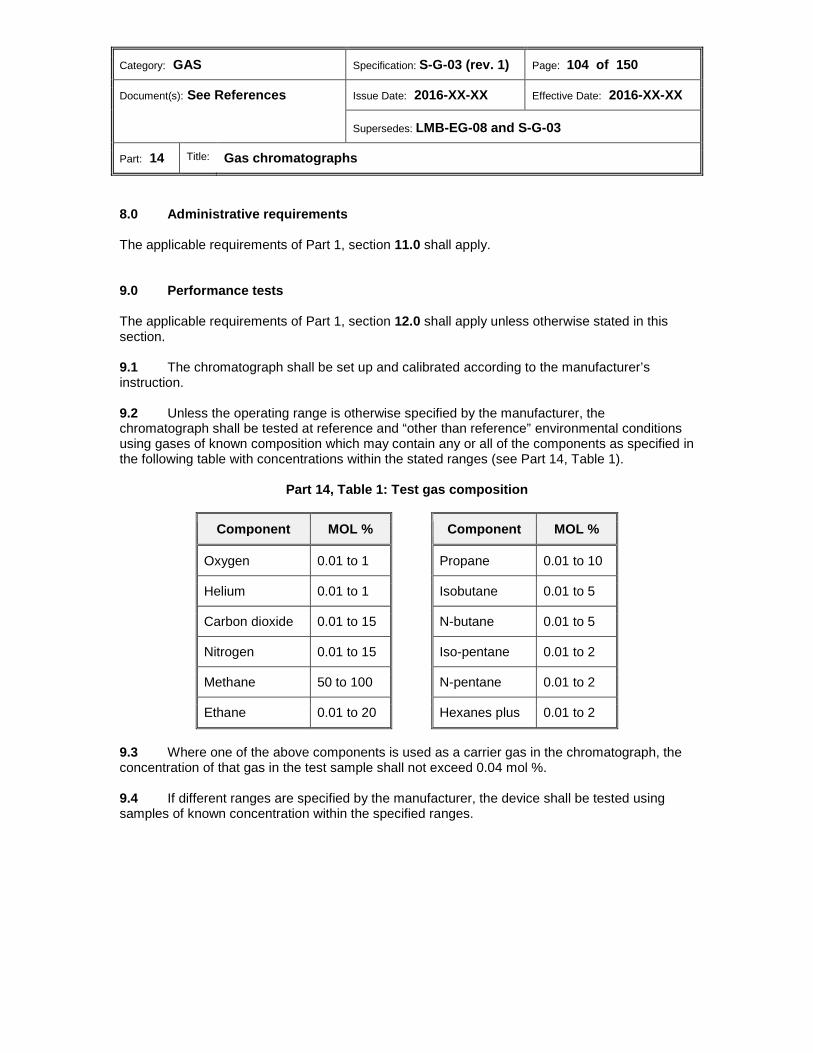
Category: GAS Specification: S-G-03 (rev. 1) Page: 104 of 150
Document(s): See References Issue Date: 2016-XX-XX Effective Date: 2016-XX-XX
Supersedes: LMB-EG-08 and S-G-03
Part: 14 Title: Gas chromatographs
Administrative requirements 8.0 The applicable requirements of Part 1, section 11.0 shall apply.
Performance tests 9.0 The applicable requirements of Part 1, section 12.0 shall apply unless otherwise stated in this section. 9.1 The chromatograph shall be set up and calibrated according to the manufacturer’s instruction. 9.2 Unless the operating range is otherwise specified by the manufacturer, the chromatograph shall be tested at reference and “other than reference” environmental conditions using gases of known composition which may contain any or all of the components as specified in the following table with concentrations within the stated ranges (see Part 14, Table 1).
Part 14, Table 1: Test gas composition
Component MOL % Component MOL %
Oxygen 0.01 to 1 Propane 0.01 to 10
Helium 0.01 to 1 Isobutane 0.01 to 5
Carbon dioxide 0.01 to 15 N-butane 0.01 to 5
Nitrogen 0.01 to 15 Iso-pentane 0.01 to 2
Methane 50 to 100 N-pentane 0.01 to 2
Ethane 0.01 to 20 Hexanes plus 0.01 to 2
9.3 Where one of the above components is used as a carrier gas in the chromatograph, the concentration of that gas in the test sample shall not exceed 0.04 mol %. 9.4 If different ranges are specified by the manufacturer, the device shall be tested using samples of known concentration within the specified ranges.
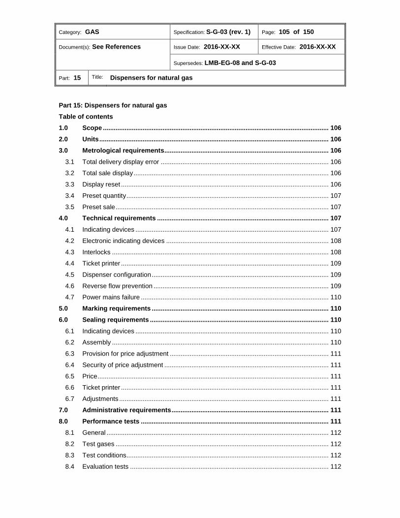
Category: GAS Specification: S-G-03 (rev. 1) Page: 105 of 150
Document(s): See References Issue Date: 2016-XX-XX Effective Date: 2016-XX-XX
Supersedes: LMB-EG-08 and S-G-03
Part: 15 Title: Dispensers for natural gas
Part 15: Dispensers for natural gas Table of contents
Scope ............................................................................................................................. 106 1.0 Units ............................................................................................................................... 106 2.0 Metrological requirements ........................................................................................... 106 3.0
3.1 Total delivery display error ............................................................................................. 106 3.2 Total sale display ............................................................................................................ 106 3.3 Display reset ................................................................................................................... 106 3.4 Preset quantity ................................................................................................................ 107 3.5 Preset sale ...................................................................................................................... 107 Technical requirements ............................................................................................... 107 4.0
4.1 Indicating devices ........................................................................................................... 107 4.2 Electronic indicating devices .......................................................................................... 108 4.3 Interlocks ........................................................................................................................ 108 4.4 Ticket printer ................................................................................................................... 109 4.5 Dispenser configuration .................................................................................................. 109 4.6 Reverse flow prevention ................................................................................................. 109 4.7 Power mains failure ........................................................................................................ 110 Marking requirements .................................................................................................. 110 5.0 Sealing requirements ................................................................................................... 110 6.0
6.1 Indicating devices ........................................................................................................... 110 6.2 Assembly ........................................................................................................................ 110 6.3 Provision for price adjustment ........................................................................................ 111 6.4 Security of price adjustment ........................................................................................... 111 6.5 Price ................................................................................................................................ 111 6.6 Ticket printer ................................................................................................................... 111 6.7 Adjustments .................................................................................................................... 111 Administrative requirements ....................................................................................... 111 7.0 Performance tests ........................................................................................................ 111 8.0
8.1 General ........................................................................................................................... 112 8.2 Test gases ...................................................................................................................... 112 8.3 Test conditions................................................................................................................ 112 8.4 Evaluation tests .............................................................................................................. 112
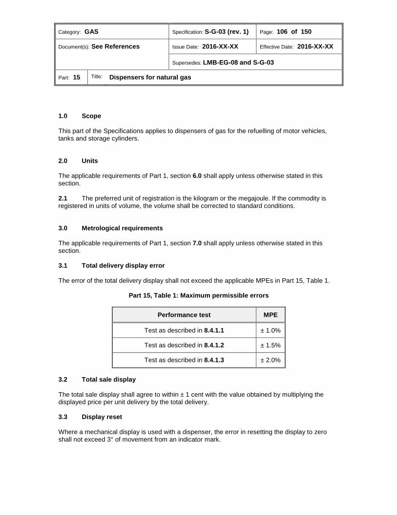
Category: GAS Specification: S-G-03 (rev. 1) Page: 106 of 150
Document(s): See References Issue Date: 2016-XX-XX Effective Date: 2016-XX-XX
Supersedes: LMB-EG-08 and S-G-03
Part: 15 Title: Dispensers for natural gas
Scope 1.0 This part of the Specifications applies to dispensers of gas for the refuelling of motor vehicles, tanks and storage cylinders.
Units 2.0 The applicable requirements of Part 1, section 6.0 shall apply unless otherwise stated in this section. 2.1 The preferred unit of registration is the kilogram or the megajoule. If the commodity is registered in units of volume, the volume shall be corrected to standard conditions.
Metrological requirements 3.0 The applicable requirements of Part 1, section 7.0 shall apply unless otherwise stated in this section. 3.1 Total delivery display error The error of the total delivery display shall not exceed the applicable MPEs in Part 15, Table 1.
Part 15, Table 1: Maximum permissible errors
Performance test MPE
Test as described in 8.4.1.1 ± 1.0%
Test as described in 8.4.1.2 ± 1.5%
Test as described in 8.4.1.3 ± 2.0%
3.2 Total sale display The total sale display shall agree to within ± 1 cent with the value obtained by multiplying the displayed price per unit delivery by the total delivery. 3.3 Display reset Where a mechanical display is used with a dispenser, the error in resetting the display to zero shall not exceed 3° of movement from an indicator mark.

Category: GAS Specification: S-G-03 (rev. 1) Page: 107 of 150
Document(s): See References Issue Date: 2016-XX-XX Effective Date: 2016-XX-XX
Supersedes: LMB-EG-08 and S-G-03
Part: 15 Title: Dispensers for natural gas
3.4 Preset quantity Where the quantity of gas to be delivered is preset, the dispenser shall deliver at least the preset quantity ± 1 minimum increment set forth in 4.1.1(a) according to the display of the dispenser before the flow is automatically stopped. 3.5 Preset sale Where the total sale of the gas to be delivered is preset, the dispenser shall deliver at least the preset total sale ± 1 cent according to the display at the dispenser before the flow is automatically stopped.
Technical requirements 4.0 The applicable requirements of Part 1, section 8.0 shall apply unless otherwise stated in this section. 4.1 Indicating devices 4.1.1 Dispensers shall be equipped with an indicating device with a display of total delivery as follows:
(a) Total delivery display: The capacity of the display shall be not less than 99.999 kg with a resolution of at least 1 g, or 9999.9 MJ with a resolution of at least 0.1 MJ, or 99.999 std m3 with a resolution of at least 0.001 std m3 (9999.9 std ft3 with a resolution of at least 0.1 std ft3).
(i) The display shall be resettable to zero.
4.1.2 Price computing indicating devices shall also have the following displays:
(a) Total sale display: The capacity of the display shall not be less than $99.99, with a resolution of 1 cent.
(i) This display shall be resettable to zero.
(b) Unit price display: This shall be an adjustable display with a resolution of 0.1 cents
per unit of metered quantity.
Category: GAS Specification: S-G-03 (rev. 1) Page: 108 of 150
Document(s): See References Issue Date: 2016-XX-XX Effective Date: 2016-XX-XX
Supersedes: LMB-EG-08 and S-G-03
Part: 15 Title: Dispensers for natural gas
4.2 Electronic indicating devices 4.2.1 Indicating devices with electronic displays shall either:
(a) automatically show all display segments for at least 0.5 seconds and blank for at least 0.5 seconds after a register is reset to zero and before another delivery is started to allow an operator to detect a segment that either indicates continuously or does not indicate; or
(b) incorporate an automatic self-testing system which checks the correct operation of
all display elements prior to commencing a delivery and on detection of a fault prevents further use of the register.
4.2.2 The quantity indications, unit price and total price indications shall remain displayed for at least five minutes after a delivery is completed or until the next transaction is initiated or the current transaction is finalized. 4.3 Interlocks 4.3.1 Indicating devices A dispenser shall be designed so that it is inoperable after a transaction is completed until the resettable indicating devices are reset to zero by means of an automatic interlock. 4.3.2 Hose pressure Delivery hoses and piping downstream of the meter shall not exceed 500 cm3 in volume unless the hoses are automatically filled with gas at the delivery pressure before a zero condition is established on the total delivery and total sale displays.
Category: GAS Specification: S-G-03 (rev. 1) Page: 109 of 150
Document(s): See References Issue Date: 2016-XX-XX Effective Date: 2016-XX-XX
Supersedes: LMB-EG-08 and S-G-03
Part: 15 Title: Dispensers for natural gas
4.4 Ticket printer 4.4.1 Ticket information Where a ticket printer forms part of or is used in conjunction with a dispenser, the ticket shall carry the following information:
(a) Name of the contractor and address at which the dispenser is installed;
(b) An identification number for the meter, or if there is only one meter, the identification number of the dispenser;
(c) The total delivery and units indicated by the register;
(d) Unit price of gas delivered (where used with a price computing register);
(e) Total sale indicated by the register (where used with a price computing register);
(f) Date that the delivery was made;
(g) An automatically advanced sequential sales number.
4.4.2 Ticket printer interlock Where a ticket printer is provided with a dispenser, an interlock shall be incorporated such that a ticket is printed for every transaction. 4.5 Dispenser configuration Dispensers intended for refuelling from both sides shall have indicators on both sides. 4.6 Reverse flow prevention There shall be means provided to prevent flow from the vessel back through the dispenser in the event that the vessel to be refilled has a higher initial pressure than the dispenser delivery pressure.
Category: GAS Specification: S-G-03 (rev. 1) Page: 110 of 150
Document(s): See References Issue Date: 2016-XX-XX Effective Date: 2016-XX-XX
Supersedes: LMB-EG-08 and S-G-03
Part: 15 Title: Dispensers for natural gas
4.7 Power mains failure Dispensers which operate from the mains power supply shall, in the event of a power outage, either:
(a) continue to operate satisfactorily for:
(i) 24 hours where a back-up supply which automatically recharges upon restoration of the power is used; or
(ii) 7 days where any other type of backup supply is used; or
(b) retain programming and metering information for the applicable period as specified
in 4.7(a), and shall be capable, upon demand, of displaying quantity, unit price and total price at any time up to 15 minutes after the power outage.
Marking requirements 5.0 In addition to the applicable requirements of Part 1, section 9.0, the following shall apply. 5.1 Where the flow rate range is not the same for all hoses, the flow rate range for each group of hoses shall be marked. 5.2 Each mass flow meter, remote electronics unit and printer (where it is located on/in the dispenser) shall bear a nameplate showing the name of the manufacturer, model or type designation and serial number of the component. 5.2.1 Each mass flow meter shall also be marked with the maximum mass flow rate for the meter. 5.2.2 Nameplates shall be clearly visible with the cover(s) removed.
Sealing requirements 6.0 The applicable requirements of Part 1, section 10.0 shall apply unless otherwise stated in this section. 6.1 Indicating devices Indicating devices of dispensers for natural gas are exempt from the requirement specified in Part 1, 10.5. 6.2 Assembly Where a dispenser comprises more than one separate assembly, the interconnecting cables and tubing shall be so arranged as to be capable of being sealed in a manner which will prevent replacement of any assembly without breaking a seal.
Category: GAS Specification: S-G-03 (rev. 1) Page: 111 of 150
Document(s): See References Issue Date: 2016-XX-XX Effective Date: 2016-XX-XX
Supersedes: LMB-EG-08 and S-G-03
Part: 15 Title: Dispensers for natural gas
6.3 Provision for price adjustment There shall be provision for adjusting the price per unit of the commodity being sold without the necessity of breaking a seal. 6.4 Security of price adjustment Access to the price setting mechanism shall be limited to authorized personnel by provision of a lock and key arrangement or equivalent. 6.5 Price It shall not be possible to change the unit price during calculation of the total price for any given delivery. 6.6 Ticket printer Where a ticket printer forms part of or is used in conjunction with a dispenser, the ticket printer shall be designed so that a jammed ticket can be removed without breaking any inspection seals. 6.7 Adjustments 6.7.1 Adjustment range of ± 2.0% 6.7.1.1 The maximum range of any adjustment affecting the accuracy of the total delivery display which is accessible without removing a portion of the exterior housing shall not exceed ± 2.0%. 6.7.1.2 Such external adjustments shall not be capable of being changed when the dispenser is in use. 6.7.1.3 Except in the case of a zero adjustment, the dispenser shall be sealable. 6.7.2 Greater than ± 2.0% adjustment range Any adjustment for accuracy of range exceeding ± 2.0% shall not be accessible without removing a sealable portion of the dispenser housing31 and shall itself be sealable.
Administrative requirements 7.0 The applicable requirements of Part 1, section 11.0 shall apply.
Performance tests 8.0 The applicable requirements of Part 1, section 12.0 shall apply unless otherwise stated in this section.
Category: GAS Specification: S-G-03 (rev. 1) Page: 112 of 150
Document(s): See References Issue Date: 2016-XX-XX Effective Date: 2016-XX-XX
Supersedes: LMB-EG-08 and S-G-03
Part: 15 Title: Dispensers for natural gas
8.1 General 8.1.1 Prior to commencing tests, the display of total delivery shall be adjusted to indicate as close to zero error as practicable. 8.1.2 No test shall result in a delivery of less than one kilogram or the minimum measured quantity. 8.1.3 Test cylinders having an initial pressure within the range from atmospheric to the declared maximum delivery pressure of the dispenser shall be partially or completely filled. 8.2 Test gases The test gas used will normally be compressed dry air, properly filtered to remove foreign matter. 8.3 Test conditions 8.3.1 Operating conditions
Reference inlet pressure 8.3.1.1
(a) For dispensers incorporating the pressure control equipment required by Canada Standards Association (CSA) B149.1-10: Natural gas and propane installation code, the reference pressure at the inlet to the dispenser shall be 22 MPa or the maximum rating declared by the manufacturer, whichever is lower.
(b) For dispensers not incorporating the pressure control equipment required by CSA
B149.1-10, the reference pressure at the inlet to the dispenser shall not exceed that required by CGA B-149.
“Other than reference” inlet pressure 8.3.1.2
The inlet pressure to the dispenser shall be set at 60% and 80% of the reference pressure specified in subsection 8.3.1.1. 8.4 Evaluation tests 8.4.1 Accuracy testing 8.4.1.1 The dispenser shall be tested at reference environmental conditions with the flowing gas temperature according to Part 1, 12.2.3.1(a) and with inlet pressures specified in subsections 8.3.1.1. (see Part 15, Table 2). 8.4.1.2 The dispenser shall be tested at reference environmental test conditions with the flowing gas temperature according to Part 1, 12.2.3.1(a) and with inlet pressures as stated in 8.3.1.2. (see Part 15 table 2)
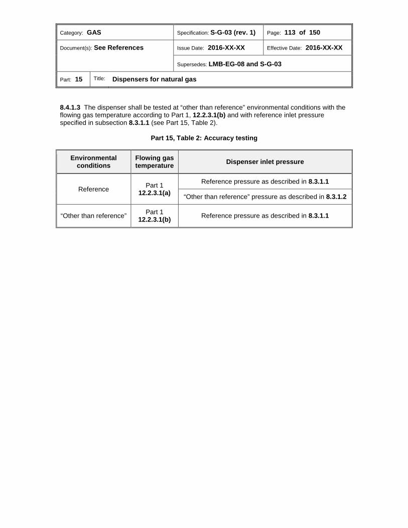
Category: GAS Specification: S-G-03 (rev. 1) Page: 113 of 150
Document(s): See References Issue Date: 2016-XX-XX Effective Date: 2016-XX-XX
Supersedes: LMB-EG-08 and S-G-03
Part: 15 Title: Dispensers for natural gas
8.4.1.3 The dispenser shall be tested at “other than reference” environmental conditions with the flowing gas temperature according to Part 1, 12.2.3.1(b) and with reference inlet pressure specified in subsection 8.3.1.1 (see Part 15, Table 2).
Part 15, Table 2: Accuracy testing
Environmental conditions
Flowing gas temperature Dispenser inlet pressure
Reference Part 1 12.2.3.1(a)
Reference pressure as described in 8.3.1.1
“Other than reference” pressure as described in 8.3.1.2
“Other than reference” Part 1 12.2.3.1(b) Reference pressure as described in 8.3.1.1
Category: GAS Specification: S-G-03 (rev. 1) Page: 114 of 150
Document(s): See References Issue Date: 2016-XX-XX Effective Date: 2016-XX-XX
Supersedes: LMB-EG-08 and S-G-03
Part: 16 Title: Pressure regulators
Part 16: Pressure regulators
Table of contents
Scope ............................................................................................................................. 115 1.0 Units ............................................................................................................................... 115 2.0 Metrological requirements ........................................................................................... 115 3.0
3.1 Maximum permissible error ............................................................................................ 115 Technical requirements ............................................................................................... 115 4.0 Marking requirements .................................................................................................. 115 5.0 Sealing requirements ................................................................................................... 116 6.0 Administrative requirements ....................................................................................... 116 7.0 Performance tests ........................................................................................................ 116 8.0
Category: GAS Specification: S-G-03 (rev. 1) Page: 115 of 150
Document(s): See References Issue Date: 2016-XX-XX Effective Date: 2016-XX-XX
Supersedes: LMB-EG-08 and S-G-03
Part: 16 Title: Pressure regulators
Scope 1.0 This part of the Specifications applies to pressure regulators submitted for approval and intended for use in pressure factor metering (PFM).
Units 2.0 The applicable requirements of Part 1, section 6.0 shall apply.
Metrological requirements 3.0 The applicable requirements of Part 1, section 7.0 shall apply unless otherwise stated in this section. 3.1 Maximum permissible error 3.1.1 For the purpose of this section, the error shall be determined as follows:
𝐸 = �𝑃𝑜 − 𝑃𝑠𝑠𝑡
𝑃𝑠𝑠𝑡 − 𝑃𝑠� × 100%
where, E = percent error Po =regulator outlet pressure (gauge) Pset =regulator set pressure (gauge) Ps = standard pressure 3.1.1.1 Strictly speaking, the ambient atmospheric pressure should be used in place of Ps in the denominator of the above equation. However, in this case, standard pressure shall be used to eliminate the effect varying atmospheric pressure would have on the repeatability of tests. 3.1.2 The MPE of the regulator output shall be ±1.0% over the range of flow rates and inlet pressures for which approval is sought.
Technical requirements 4.0 The applicable requirements of Part 1, section 8.0 shall apply.
Marking requirements 5.0 In addition to the applicable requirements of Part 1, section 9.0, the following shall apply.
Category: GAS Specification: S-G-03 (rev. 1) Page: 116 of 150
Document(s): See References Issue Date: 2016-XX-XX Effective Date: 2016-XX-XX
Supersedes: LMB-EG-08 and S-G-03
Part: 16 Title: Pressure regulators
5.1 Subject to 5.1.1, a nameplate, tag, sticker or other suitable means shall be provided for marking inlet pressure range, outlet pressure set point, orifice size(s) and spring identification. 5.1.1 The method used for providing the markings shall ensure the markings are accessible during PFM inspections without the requirement for specialized equipment.
Sealing requirements 6.0 The applicable requirements of Part 1, section 10.0 shall apply.
Administrative requirements 7.0 The applicable requirements of Part 1, section 11.0 shall apply.
Performance tests 8.0 The applicable requirements of Part 1, section 12.0 shall apply unless otherwise stated in this section. 8.1 The applicant shall conduct tests at various combinations of inlet pressures, outlet pressures, flow rates, springs and orifices for which approval of type is sought at reference and “other than reference” environmental conditions. 8.2 Test points shall be selected from within the regulator's operating range to establish the acceptability of the manufacturer's published performance data. 8.3 Tests for any combination of orifices, springs and any other interchangeable components will consist of adjusting the regulator according to the manufacturer's instructions, varying the flow rate while maintaining the inlet pressure constant, and varying the inlet pressure while maintaining the flow rate constant. 8.3.1 Where no specific adjustment instructions are provided by the manufacturer, the set pressure shall be adjusted with the inlet pressure at 50% of its range and the flow rate at 10% of its range.
Category: GAS Specification: S-G-03 (rev. 1) Page: 117 of 150
Document(s): See References Issue Date: 2016-XX-XX Effective Date: 2016-XX-XX
Supersedes: LMB-EG-08 and S-G-03
Part: 17 Title: Temperature and pressure transmitters
Part 17: Temperature and pressure transmitters
Table of contents
Scope ............................................................................................................................. 118 1.0 Units ............................................................................................................................... 118 2.0 Metrological requirements ........................................................................................... 118 3.0
3.1 Maximum permissible errors .......................................................................................... 118 Technical requirements ............................................................................................... 119 4.0 Marking requirements .................................................................................................. 119 5.0
5.1 Terminal markings .......................................................................................................... 119 5.2 Operating information ..................................................................................................... 119 5.3 Differential pressure transmitters .................................................................................... 119 Sealing requirements ................................................................................................... 119 6.0 Administrative requirements ....................................................................................... 119 7.0 Performance tests ........................................................................................................ 119 8.0
8.1 Test conditions................................................................................................................ 120 8.2 Evaluation tests .............................................................................................................. 120

Category: GAS Specification: S-G-03 (rev. 1) Page: 118 of 150
Document(s): See References Issue Date: 2016-XX-XX Effective Date: 2016-XX-XX
Supersedes: LMB-EG-08 and S-G-03
Part: 17 Title: Temperature and pressure transmitters
Scope 1.0 This part of the Specifications applies to stand alone devices submitted for approval which provide an electrical output in response to temperature and pressure.32
Units 2.0 The applicable requirements of Part 1, section 6.0 shall apply.
Metrological requirements 3.0 The applicable requirements of Part 1, section 7.0 shall apply unless otherwise stated in this section. 3.1 Maximum permissible errors The MPEs in Part 17, Table 1 shall apply.
Part 17, Table 1: Maximum permissible errors for transmitters
Transmitter type
Performance test conditions MPE
Environmental conditions Operating conditions
Temperature Reference As specified in 8.1.1.1(a) ± 0.5 ºC
“Other than reference” As specified in 8.1.1.1(b) ± 1.0 ºC
Pressure (absolute
and gauge)
Reference As specified in 8.1.1.2
± 0.5% of reading
“Other than reference” ± 1.0% of reading
Differential pressure
Reference
As specified in 8.1.1.3(a) ± 0.5% of reading33
± 1.0% of reading34
As specified in 8.1.1.3(b) ± 1.0% of reading35
± 2.0% of reading36
“Other than reference” As specified in 8.1.1.3(a) ± 1.0% of reading37
± 2.0% of reading38
Category: GAS Specification: S-G-03 (rev. 1) Page: 119 of 150
Document(s): See References Issue Date: 2016-XX-XX Effective Date: 2016-XX-XX
Supersedes: LMB-EG-08 and S-G-03
Part: 17 Title: Temperature and pressure transmitters
Technical requirements 4.0 The applicable requirements of Part 1, section 8.0 shall apply.
Marking requirements 5.0 In addition to the applicable requirements of Part 1, section 9.0, the following shall apply. 5.1 Terminal markings The connection terminals shall be identified by markings on the device or by a table or a schematic diagram permanently affixed to the device. 5.2 Operating information Where the operating temperature range or pressure range can be adjusted by the contractor, a nameplate, tag, sticker or other suitable means shall be provided for marking the temperature range or pressure range for which the device is calibrated (may be made available from electronic indicators). 5.3 Differential pressure transmitters The pressure connection ports shall be marked to distinguish the low pressure port from the high pressure port.
Sealing requirements 6.0 The applicable requirements of Part 1, section 10.0 shall apply.
Administrative requirements 7.0 The applicable requirements of Part 1, section 11.0 shall apply.
Performance tests 8.0 The applicable requirements of Part 1, section 12.0 shall apply unless otherwise stated in this section.
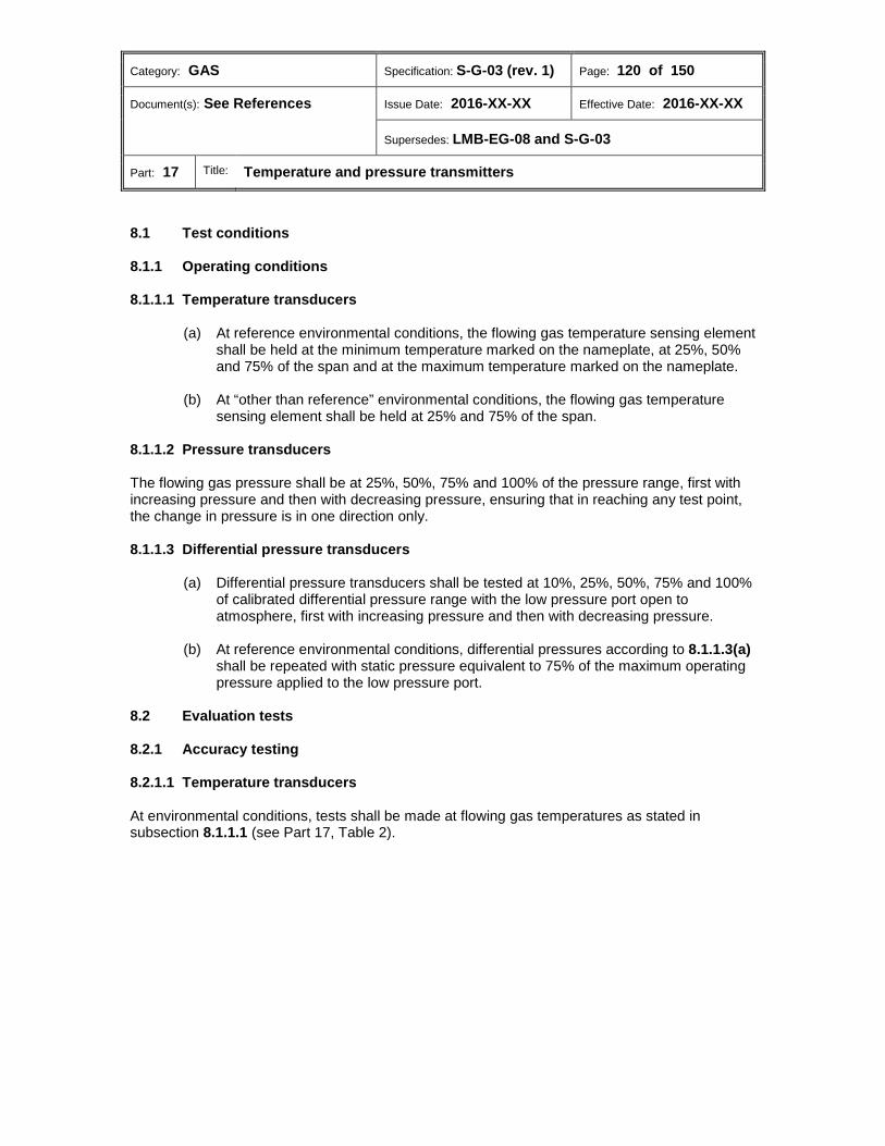
Category: GAS Specification: S-G-03 (rev. 1) Page: 120 of 150
Document(s): See References Issue Date: 2016-XX-XX Effective Date: 2016-XX-XX
Supersedes: LMB-EG-08 and S-G-03
Part: 17 Title: Temperature and pressure transmitters
8.1 Test conditions 8.1.1 Operating conditions
Temperature transducers 8.1.1.1
(a) At reference environmental conditions, the flowing gas temperature sensing element shall be held at the minimum temperature marked on the nameplate, at 25%, 50% and 75% of the span and at the maximum temperature marked on the nameplate.
(b) At “other than reference” environmental conditions, the flowing gas temperature
sensing element shall be held at 25% and 75% of the span.
Pressure transducers 8.1.1.2 The flowing gas pressure shall be at 25%, 50%, 75% and 100% of the pressure range, first with increasing pressure and then with decreasing pressure, ensuring that in reaching any test point, the change in pressure is in one direction only.
Differential pressure transducers 8.1.1.3
(a) Differential pressure transducers shall be tested at 10%, 25%, 50%, 75% and 100% of calibrated differential pressure range with the low pressure port open to atmosphere, first with increasing pressure and then with decreasing pressure.
(b) At reference environmental conditions, differential pressures according to 8.1.1.3(a)
shall be repeated with static pressure equivalent to 75% of the maximum operating pressure applied to the low pressure port.
8.2 Evaluation tests 8.2.1 Accuracy testing
Temperature transducers 8.2.1.1 At environmental conditions, tests shall be made at flowing gas temperatures as stated in subsection 8.1.1.1 (see Part 17, Table 2).
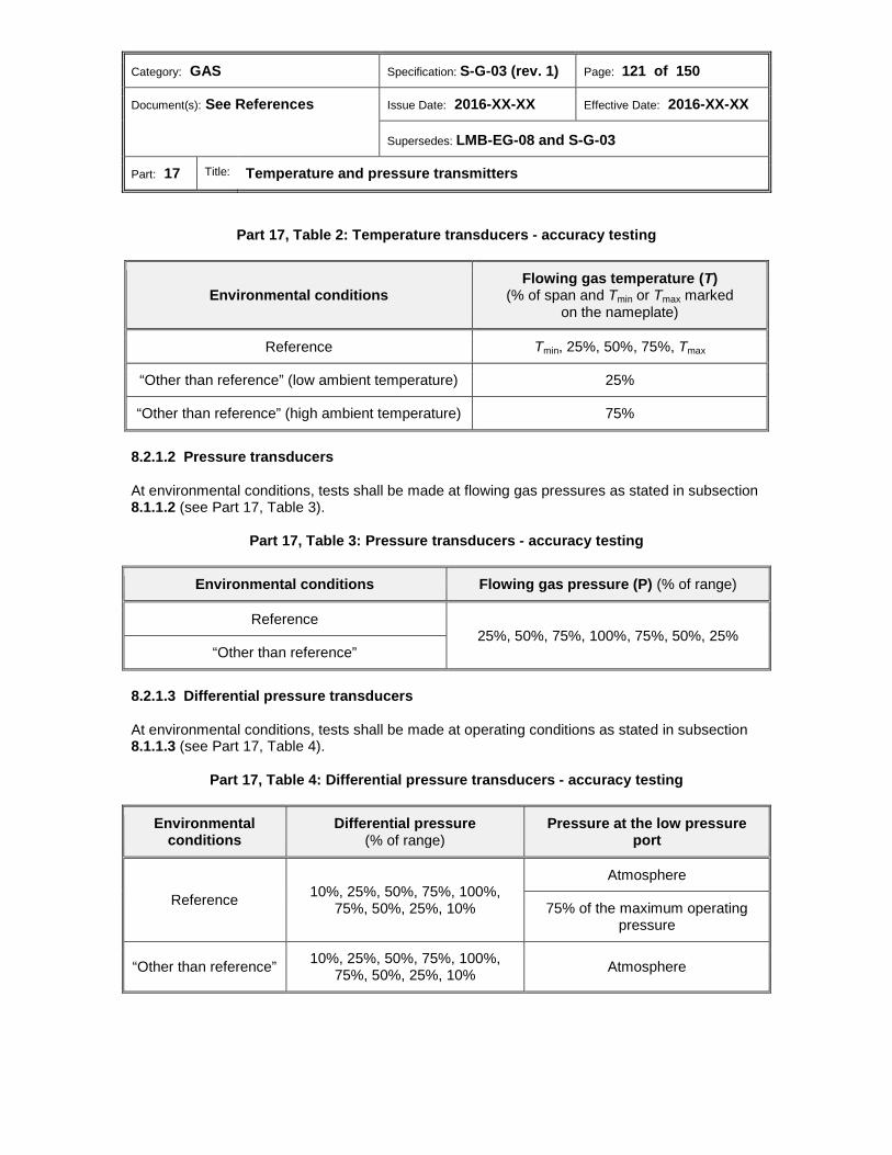
Category: GAS Specification: S-G-03 (rev. 1) Page: 121 of 150
Document(s): See References Issue Date: 2016-XX-XX Effective Date: 2016-XX-XX
Supersedes: LMB-EG-08 and S-G-03
Part: 17 Title: Temperature and pressure transmitters
Part 17, Table 2: Temperature transducers - accuracy testing
Environmental conditions Flowing gas temperature (T)
(% of span and Tmin or Tmax marked on the nameplate)
Reference Tmin, 25%, 50%, 75%, Tmax
“Other than reference” (low ambient temperature) 25%
“Other than reference” (high ambient temperature) 75%
Pressure transducers 8.2.1.2
At environmental conditions, tests shall be made at flowing gas pressures as stated in subsection 8.1.1.2 (see Part 17, Table 3).
Part 17, Table 3: Pressure transducers - accuracy testing
Environmental conditions Flowing gas pressure (P) (% of range)
Reference 25%, 50%, 75%, 100%, 75%, 50%, 25%
“Other than reference”
Differential pressure transducers 8.2.1.3
At environmental conditions, tests shall be made at operating conditions as stated in subsection 8.1.1.3 (see Part 17, Table 4).
Part 17, Table 4: Differential pressure transducers - accuracy testing
Environmental conditions
Differential pressure (% of range)
Pressure at the low pressure port
Reference 10%, 25%, 50%, 75%, 100%, 75%, 50%, 25%, 10%
Atmosphere
75% of the maximum operating pressure
“Other than reference” 10%, 25%, 50%, 75%, 100%, 75%, 50%, 25%, 10% Atmosphere

Category: GAS Specification: S-G-03 (rev. 1) Page: 122 of 150
Document(s): See References Issue Date: 2016-XX-XX Effective Date: 2016-XX-XX
Supersedes: LMB-EG-08 and S-G-03
Part: 18 Title: Correction function of gas meters
Part 18: Correction function of gas meters
Table of contents
Scope ............................................................................................................................. 123 1.0 Metrological requirements ........................................................................................... 123 2.0
2.1 General ........................................................................................................................... 123 2.2 Error correction methods ................................................................................................ 123 Technical requirements ............................................................................................... 124 3.0 Marking requirements .................................................................................................. 124 4.0 Performance tests ........................................................................................................ 125 5.0

Category: GAS Specification: S-G-03 (rev. 1) Page: 123 of 150
Document(s): See References Issue Date: 2016-XX-XX Effective Date: 2016-XX-XX
Supersedes: LMB-EG-08 and S-G-03
Part: 18 Title: Correction function of gas meters
Scope 1.0 1.1 This part of the Specifications provides the requirements for the approval evaluation of meter performance enhancement schemes based on the linearization or curve fitting of uncorrected or raw flow calibration data. 1.2 This part applies to schemes which are incorporated in flow computers, correction devices, flow meters and supporting software external to the device, and are intended to be user accessible and programmable at the time of initial verification. 1.3 This section shall be read in conjunction with the specification to each type of meter and ancillary device in subsequent sections specific thereto.
Metrological requirements 2.0 2.1 General 2.1.1 Prior to correction, the error of the meter/device where the correction function resides shall not exceed the MPE for the meter/device. 2.1.2 The error correction shall not exceed the MPE for the meter/device where the correction function resides. 2.1.3 The error correction and correction factor applied shall not exceed ± 0.1% of the error and the correction factor as determined in accordance with the correction method for which approval is sought. 2.1.4 Correction for flow rates or input parameters below the minimum test point for which an error has been established shall be the correction established at the minimum test point. 2.1.5 Correction for flow rates or input parameters above the maximum test point for which an error has been established shall be the correction established at the maximum test point. 2.2 Error correction methods Correction for a known error shall be based on one of the following methods. 2.2.1 Linear interpolation (point-to-point linearization) 2.2.1.1 The error between adjacent predetermined calibration values shall be determined in accordance with the equation for a straight line (𝑌 = 𝑚𝑚 + 𝑏). 2.2.1.2 The meter performance correction values (either meter factors or K factors) shall be based on the error as determined for the current flow rate or input parameter as applicable. 2.2.1.3 The values specified in 2.2.1.2 shall be used to correct the raw meter pulse signal or input parameter and provide an estimate of the true value of flow or input parameter as applicable.
Category: GAS Specification: S-G-03 (rev. 1) Page: 124 of 150
Document(s): See References Issue Date: 2016-XX-XX Effective Date: 2016-XX-XX
Supersedes: LMB-EG-08 and S-G-03
Part: 18 Title: Correction function of gas meters
2.2.2 Modeling equation 2.2.2.1 A modeling equation (such as a fourth-order equation) that results in a series of coefficients (a, b, c, d, e, etc.) and an estimate of the uncertainty of the curve fit being provided shall be used. 2.2.2.2 The equation coefficients specified in 2.2.2.1 shall be programmed into the device where the correction function resides. 2.2.2.3 Corrections shall be calculated using the same equation, by the devices in which the correction function resides, and used to correct the metering measurement unit or input parameter and provide an estimate of the true value of flow or input parameter. 2.2.3 Discreet step interpolation 2.2.3.1 The error between adjacent predetermined calibration values shall be the calibration value determined at the lower percentage of the range for the meter/device. 2.2.3.2 The requirements specified in 2.2.1.2 and 2.2.1.3 shall apply.
Technical requirements 3.0 All parameters which are not measured but are necessary for correcting shall be contained in the device where the correction function resides before any measurement operation is carried out.
Marking requirements 4.0 4.1 In addition to the applicable requirements of Part 1, section 9.0, the following information shall reside in the device performing the correction and shall be verifiable:
(a) Each test point at which the device was tested and the error at the test point;
(b) The current flow rate or input parameter being used by the correction function;
(c) The correction factor applied as determined by the correction function.

Category: GAS Specification: S-G-03 (rev. 1) Page: 125 of 150
Document(s): See References Issue Date: 2016-XX-XX Effective Date: 2016-XX-XX
Supersedes: LMB-EG-08 and S-G-03
Part: 18 Title: Correction function of gas meters
Performance tests 5.0 5.1 As a minimum, the applicant shall conduct the following tests and submit the test results with the application:
(a) A performance test below the minimum test point for which a known error has been established.
(b) A performance test above the maximum test point for which a known error has been
established.
(c) Performance tests at different test points, between the minimum and maximum flow rates or input parameters for which approval is sought.
Category: GAS Specification: S-G-03 (rev. 1) Page: 126 of 150
Document(s): See References Issue Date: 2016-XX-XX Effective Date: 2016-XX-XX
Supersedes: LMB-EG-08 and S-G-03
Part: 19 Title: Densitometers
Part 19: Densitometers
Table of contents
Scope ............................................................................................................................. 127 1.0 Units ............................................................................................................................... 127 2.0 Metrological requirements ........................................................................................... 127 3.0
3.1 Maximum permissible errors .......................................................................................... 127 Technical requirements ............................................................................................... 127 4.0
4.1 Filters .............................................................................................................................. 127 4.2 Gas flow passages ......................................................................................................... 127 Marking requirements .................................................................................................. 128 5.0 Sealing requirements ................................................................................................... 128 6.0 Administrative requirements ....................................................................................... 128 7.0 Performance tests ........................................................................................................ 128 8.0
8.1 Test conditions................................................................................................................ 128 8.2 Flow rate ......................................................................................................................... 129 8.3 Test gas .......................................................................................................................... 129 8.4 Evaluation tests .............................................................................................................. 129

Category: GAS Specification: S-G-03 (rev. 1) Page: 127 of 150
Document(s): See References Issue Date: 2016-XX-XX Effective Date: 2016-XX-XX
Supersedes: LMB-EG-08 and S-G-03
Part: 19 Title: Densitometers
Scope 1.0 This part of the Specifications applies to devices used for the measurement of absolute gas density.
Units 2.0 The applicable requirements of Part 1, section 6.0 shall apply.
Metrological requirements 3.0 The applicable requirements of Part 1, section 7.0 shall apply unless otherwise stated in this section. 3.1 Maximum permissible errors The following MPEs shall apply at any point within the density range for which approval is sought (see Part 19, Table 1).
Part 19, Table 1: Maximum permissible errors
Environmental conditions MPE
Reference ± 0.3%
“Other than reference” ± 0.5%
Technical requirements 4.0 In addition to the applicable requirements of Part 1, section 8.0, the following shall apply. 4.1 Filters Where the design of the device is such that foreign matter in gas can adversely affect its operation or impair its accuracy, the manufacturer shall incorporate suitable filters. 4.2 Gas flow passages The inlet and outlet connections and the gas passages of a densitometer so equipped shall be of sufficient size to ensure minimal pressure drop with adequate gas flow through the device in order to respond rapidly to changes of density in the metered gas.

Category: GAS Specification: S-G-03 (rev. 1) Page: 128 of 150
Document(s): See References Issue Date: 2016-XX-XX Effective Date: 2016-XX-XX
Supersedes: LMB-EG-08 and S-G-03
Part: 19 Title: Densitometers
Marking requirements 5.0 In addition to the applicable requirements of Part 1, section 9.0, the following shall apply. 5.1 The following information shall be marked on the nameplate, where applicable:
(a) Operating density range;
(b) Minimum required gas flow through the device;
(c) Output signal characteristics and, where linear, signal to density conversion factor;
(d) Additional necessary information identified by MC. 5.2 Where the values of operating parameters may be set by the contractor, the manufacturer shall provide a nameplate, tag, sticker or other suitable means for marking the required information.
Sealing requirements 6.0 The applicable requirements of Part 1, section 10.0 shall apply.
Administrative requirements 7.0 The applicable requirements of Part 1, section 11.0 shall apply.
Performance tests 8.0 The applicable requirements of Part 1, section 12.0 shall apply unless otherwise stated in this section. 8.1 Test conditions 8.1.1 Operating conditions
Flowing gas pressure 8.1.1.1 Variation of the flowing gas pressure shall produce densities corresponding to 10%, 50% and 90% of the nominal range of density for the device.

Category: GAS Specification: S-G-03 (rev. 1) Page: 129 of 150
Document(s): See References Issue Date: 2016-XX-XX Effective Date: 2016-XX-XX
Supersedes: LMB-EG-08 and S-G-03
Part: 19 Title: Densitometers
Flowing gas temperature 8.1.1.2 Where a gas is used for testing at “other than reference” environmental conditions, the following shall apply (see Part 1, Table 1).
(a) For the low ambient temperature tests, the test gas shall be conditioned so that its temperature at the inlet of the device is -10 °C.
(b) For the high ambient temperature tests, the test gas shall be conditioned so that its
temperature at the inlet to the device is 30 °C.
Part 19, Table 2: Flowing test gas temperatures
“Other than reference” environmental conditions Flowing gas temperature
Low ambient temperature: -30 °C -10 °C
High ambient temperature: 40 °C 30 °C
8.2 Flow rate The flow of gas through the densitometer, where applicable, shall be set at a minimum rate specified by the manufacturer or at zero flow where not specified. 8.3 Test gas Chemically pure, dry nitrogen39 shall normally be used as the test gas. 8.4 Evaluation tests 8.4.1 At reference environmental conditions, tests shall be made at the flow rate specified in 8.2 and at a flowing gas pressure corresponding to subsection 8.1.1.1 (see Part 19, Table 2). 8.4.2 At “other than reference” environmental conditions, tests shall be made at the flow rate specified in 8.2 and at operating conditions corresponding to subsection 8.1.1 (see Part 19, Table 2).

Category: GAS Specification: S-G-03 (rev. 1) Page: 130 of 150
Document(s): See References Issue Date: 2016-XX-XX Effective Date: 2016-XX-XX
Supersedes: LMB-EG-08 and S-G-03
Part: 19 Title: Densitometers
Part 19, Table 2: Accuracy testing
Environmental conditions Flowing gas temperature Flowing gas pressure
Reference As specified in Part 1, 12.2.3.1(a) Variation of the flowing gas
pressure shall produce densities corresponding to 10%, 50% and
90% of the nominal range of density for the device.
“Other than reference” (low ambient temperature: -30 °C) -10 °C
“Other than reference” (high ambient temperature: 40 °C) 30 °C
Category: GAS Specification: S-G-03 (rev. 1) Page: 131 of 150
Document(s): See References Issue Date: 2016-XX-XX Effective Date: 2016-XX-XX
Supersedes: LMB-EG-08 and S-G-03
Part: 20 Title: Flow conditioners used in gas measurement systems
Part 20: Flow conditioners used in gas measurement systems
Table of contents
Scope ............................................................................................................................. 132 1.0 Units ............................................................................................................................... 132 2.0 Metrological requirements ........................................................................................... 132 3.0 Technical requirements ............................................................................................... 132 4.0 Marking requirements .................................................................................................. 132 5.0 Sealing requirements ................................................................................................... 133 6.0 Administrative requirements ....................................................................................... 133 7.0
7.1 Application for approval .................................................................................................. 133
Category: GAS Specification: S-G-03 (rev. 1) Page: 132 of 150
Document(s): See References Issue Date: 2016-XX-XX Effective Date: 2016-XX-XX
Supersedes: LMB-EG-08 and S-G-03
Part: 20 Title: Flow conditioners used in gas measurement systems
Scope 1.0 This part of the Specifications applies to flow conditioners used in natural gas custody transfer metering systems.
Units 2.0 The applicable requirements of Part 1, section 6.0 shall apply.
Metrological requirements 3.0 In addition to the applicable requirements of Part 1, section 7.0, the following shall apply. 3.1 The flow conditioner and piping configuration shall reduce pipeline disturbances resulting in a measurement system improvement of 1/2 the limit of error of the meter installed.
Technical requirements 4.0 The applicable requirements of Part 1, section 8.0 shall apply.
Marking requirements 5.0 In addition to the applicable requirements of Part 1, section 9.0, the following shall apply. 5.1 The model/type designation and the approval number shall be stamped on the edge of the flow conditioner flange. 5.1.1 This marking shall be legible and visible when the conditioner is installed. 5.2 The manufacturer’s inspection marking (if other than the marking in 5.1) shall also be stamped on the top edge of the flow conditioner to attest to the conformance of the flow conditioner to the manufacturer’s design and construction specifications. 5.3 The pipe size and schedule of the upstream pipe that the flow conditioner is intended to be used with shall be stamped on the downstream face of the plate or on the flange. 5.4 Where the flow conditioner is not of a flange mounted type, the required markings shall be stamped on the downstream face of the plate and on a nameplate/tag to allow for the identification of the model and its status with regards to the manufacturer’s inspection carried out in accordance with design requirements, without disassembling the meter run.

Category: GAS Specification: S-G-03 (rev. 1) Page: 133 of 150
Document(s): See References Issue Date: 2016-XX-XX Effective Date: 2016-XX-XX
Supersedes: LMB-EG-08 and S-G-03
Part: 20 Title: Flow conditioners used in gas measurement systems
Sealing requirements 6.0 The applicable requirements of Part 1, section 10.0 shall apply.
Administrative requirements 7.0 The applicable requirements of Part 1, section 11.0 shall apply unless otherwise stated in this section. 7.1 Application for approval 7.1.1 Design Along with the application for approval, the applicant shall state the following flow conditioner design parameters with their tolerances.
(a) Outside plate diameter (and outer flange where applicable);
(b) Plate thickness;
(c) Number of bore holes and their pattern;
(d) Bore hole dimensions, as a function of the inside pipe diameter of the pipe in which the conditioner is intended to be used.
7.1.2 Construction material The applicant shall provide a listing of the acceptable materials of which the flow conditioner may be constructed. 7.1.3 Test data 7.1.3.1 The applicant shall submit test data, from a test facility recognized by MC, that demonstrates improvement in baseline conditions for specific the meter types. 7.1.3.2 Subject to 7.1.3.3, the test data supplied shall conform to the latest version of the applicable AGA report for the type or class of meters the conditioner is intended to be used with.
Category: GAS Specification: S-G-03 (rev. 1) Page: 134 of 150
Document(s): See References Issue Date: 2016-XX-XX Effective Date: 2016-XX-XX
Supersedes: LMB-EG-08 and S-G-03
Part: 20 Title: Flow conditioners used in gas measurement systems
7.1.3.3 Where the applicable AGA report does not provide test data requirements for the approval of flow conditioners, the following test data requirements shall apply:
(a) Appendix 2-D of AGA Report No.3: Orifice Metering of Natural Gas and Other Related Hydrocarbon Fluids, Part 2: Specification and Installation Requirements, (Fourth edition, 2000); or
(b) Test data conforming to the requirements as set out by another industry-recognized authority, subject to the following:
(i) Identification of the industry-recognized authority and the requirements
document;
(ii) Provision of the flow conditioner approval requirements document to MC, where requested;
(iii) MC approval of the use of the approval requirement document for the
submission of test data. 7.1.3.4 The applicant shall supply:
(a) subject to 7.1.3.4(a)(i), test data for each combination of flow conditioner model and meter type or class for which approval is being sought;
(i) The test data shall be supplied for the Qmin and Qmax flow rates for each
meter type or class for which approval is being sought (i.e. Qmin for lowest capacity meter in the meter type or class and Qmax for the largest capacity meter in the meter type or class).
(b) the flow range of the flow conditioner, if less than the range of the meter(s);
(c) the test medium used to conduct testing (natural gas/air).
7.1.4 Configuration 7.1.4.1 Subject to 7.1.4.2, the manufacturer shall supply the piping configuration requirements for each type of meter the flow conditioner is intended to be used with. 7.1.4.2 The piping configuration requirements shall include the following:
(a) The distance between the meter and flow conditioner stated in the form of the number of pipe diameters;
(b) The downstream meter tube requirements;
(c) The distance between the flow conditioner and any elbows or valves upstream of it
stated in the form of the number of pipe diameters.
Category: GAS Specification: S-G-03 (rev. 1) Page: 135 of 150
Document(s): See References Issue Date: 2016-XX-XX Effective Date: 2016-XX-XX
Supersedes: LMB-EG-08 and S-G-03
Part: 20 Title: Flow conditioners used in gas measurement systems
7.1.4.3 Any limitations shall be stated, such as the number of elbows or partially opened valves preceding the flow conditioner.

Category: GAS Specification: S-G-03 (rev. 1) Page: 136 of 150
Document(s): See References Issue Date: 2016-XX-XX Effective Date: 2016-XX-XX
Supersedes: LMB-EG-08 and S-G-03
Part: 21 Title: Conditioning orifice plates
Part 21: Conditioning orifice plates
Table of contents
Scope ............................................................................................................................. 137 1.0 Terminology .................................................................................................................. 137 2.0 Units ............................................................................................................................... 137 3.0 Metrological requirements ........................................................................................... 137 4.0
4.1 Algorithm ......................................................................................................................... 137 4.2 Disturbance factors ......................................................................................................... 137 Technical requirements ............................................................................................... 137 5.0 Marking requirements .................................................................................................. 138 6.0 Sealing requirements ................................................................................................... 138 7.0 Administrative requirements ....................................................................................... 138 8.0
8.1 Application for approval .................................................................................................. 138 Performance tests ........................................................................................................ 139 9.0
Category: GAS Specification: S-G-03 (rev. 1) Page: 137 of 150
Document(s): See References Issue Date: 2016-XX-XX Effective Date: 2016-XX-XX
Supersedes: LMB-EG-08 and S-G-03
Part: 21 Title: Conditioning orifice plates
Scope 1.0 This part of the Specifications applies to conditioning orifice plates and related meter run assembly components.
Terminology 2.0 Conditioning orifice plate (plaques à orifices tranquillisante) A multi-hole orifice plate designed to simultaneously function as a differential pressure element and as a flow conditioner. Conditioning orifice plates are designed for use with meter tubes that are shorter in length than those used with conventional orifice plates.
Units 3.0 The applicable requirements of Part 1, section 6.0 shall apply.
Metrological requirements 4.0 The requirements of Part 9, section 4.0 shall apply unless otherwise stated in this section. 4.1 Algorithm 4.1.1 Subject to 4.1.2, the algorithm used to translate the primary measurements of pressure and temperature into volumetric flow shall be the algorithm derived in Appendix D. 4.1.2 Where the applicant can show sufficient evidence that an alternative algorithm is suitable, that algorithm shall be authorized for use in the NOA. 4.2 Disturbance factors The difference between the meter accuracy established during meter error testing and the meter accuracy established during meter flow disturbance testing as described in section 9.0 shall not exceed the errors specified in section 4.0.
Technical requirements 5.0 In addition to the applicable requirements of Part 1, section 8.0, the conditioning orifice plate shall be used in conjunction with an approved orifice fitting.

Category: GAS Specification: S-G-03 (rev. 1) Page: 138 of 150
Document(s): See References Issue Date: 2016-XX-XX Effective Date: 2016-XX-XX
Supersedes: LMB-EG-08 and S-G-03
Part: 21 Title: Conditioning orifice plates
Marking requirements 6.0 The applicable requirements of Part 1, section 9.0 shall apply unless otherwise stated in this section. 6.1 In addition to the markings required in Part 1, 9.1(a), (b), (c), and (d), the following information shall be indelibly marked on the downstream face or on the flange of the conditioning orifice plate, without distorting it:
(a) Beta ratio;
(b) Inside diameter of the meter tube;
(c) Calibration factor (Fc).
Sealing requirements 7.0 The applicable requirements of Part 1, section 10.0 shall apply.
Administrative requirements 8.0 The applicable requirements of Part 1, section 11.0 shall apply unless otherwise stated in this section. 8.1 Application for approval 8.1.1 The manufacturer shall provide supporting test data relating to the maximum permissible meter / meter tube step change and maximum permissible meter non-axial alignment.
Category: GAS Specification: S-G-03 (rev. 1) Page: 139 of 150
Document(s): See References Issue Date: 2016-XX-XX Effective Date: 2016-XX-XX
Supersedes: LMB-EG-08 and S-G-03
Part: 21 Title: Conditioning orifice plates
8.1.2 Where a manufacturer intends to have a conditioning orifice plate reverified by means of dimensional inspection, the following conditions shall apply:
(a) Critical physical dimensions and their permitted deviations (tolerances) shall be provided by the manufacturer/applicant. Examples of which may include, but are not necessarily limited to, the following:
· pipe inside diameter
· plate thickness
· number of bore holes
· average of bore diameters
· diameter of bore hole centres
· surface roughness
· bevel, if applicable
· overall plate diameter
(b) The manufacturer/applicant shall provide test data demonstrating that the
dimensional tolerances do not introduce a deviation in performance that is greater than that specified in section 4.0.
Performance tests 9.0 The requirements of Part 9, section 9.0 shall apply.
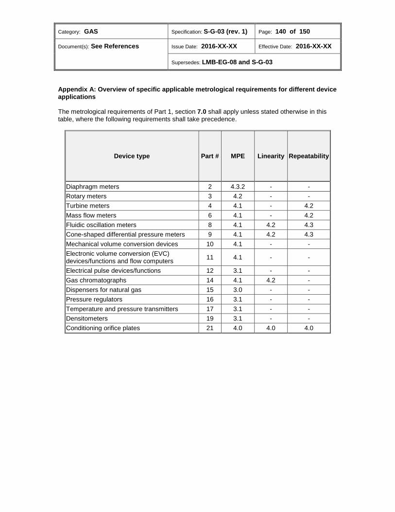
Category: GAS Specification: S-G-03 (rev. 1) Page: 140 of 150
Document(s): See References Issue Date: 2016-XX-XX Effective Date: 2016-XX-XX
Supersedes: LMB-EG-08 and S-G-03
Appendix A: Overview of specific applicable metrological requirements for different device applications The metrological requirements of Part 1, section 7.0 shall apply unless stated otherwise in this table, where the following requirements shall take precedence.
Device type Part # MPE Linearity Repeatability
Diaphragm meters 2 4.3.2 - - Rotary meters 3 4.2 - - Turbine meters 4 4.1 - 4.2 Mass flow meters 6 4.1 - 4.2 Fluidic oscillation meters 8 4.1 4.2 4.3 Cone-shaped differential pressure meters 9 4.1 4.2 4.3 Mechanical volume conversion devices 10 4.1 - - Electronic volume conversion (EVC) devices/functions and flow computers 11 4.1 - -
Electrical pulse devices/functions 12 3.1 - - Gas chromatographs 14 4.1 4.2 - Dispensers for natural gas 15 3.0 - - Pressure regulators 16 3.1 - - Temperature and pressure transmitters 17 3.1 - - Densitometers 19 3.1 - - Conditioning orifice plates 21 4.0 4.0 4.0
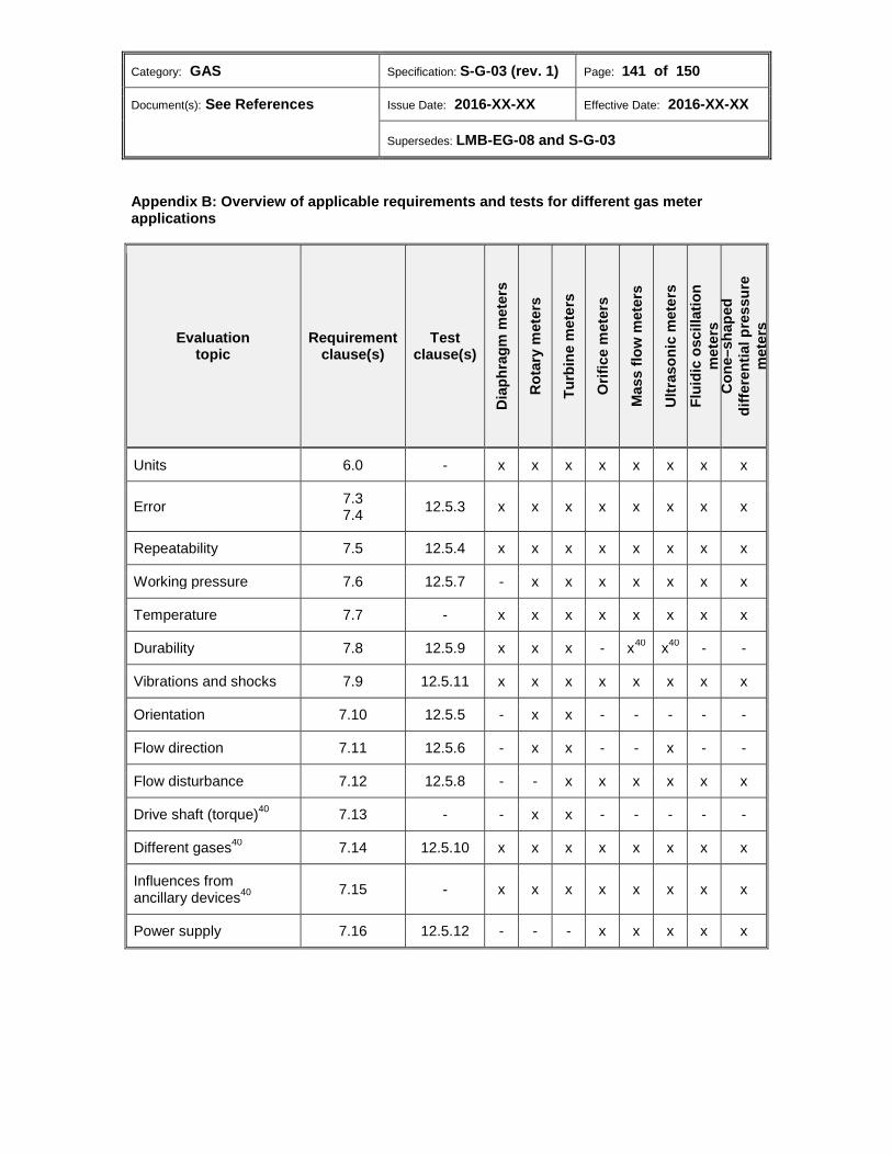
Category: GAS Specification: S-G-03 (rev. 1) Page: 141 of 150
Document(s): See References Issue Date: 2016-XX-XX Effective Date: 2016-XX-XX
Supersedes: LMB-EG-08 and S-G-03
Appendix B: Overview of applicable requirements and tests for different gas meter applications
Evaluation topic
Requirement clause(s)
Test clause(s)
Dia
phra
gm m
eter
s
Rot
ary
met
ers
Turb
ine
met
ers
Orif
ice
met
ers
Mas
s flo
w m
eter
s
Ultr
ason
ic m
eter
s Fl
uidi
c os
cilla
tion
met
ers
Con
e–sh
aped
di
ffere
ntia
l pre
ssur
e m
eter
s
Units 6.0 - x x x x x x x x
Error 7.3 7.4 12.5.3 x x x x x x x x
Repeatability 7.5 12.5.4 x x x x x x x x
Working pressure 7.6 12.5.7 - x x x x x x x
Temperature 7.7 - x x x x x x x x
Durability 7.8 12.5.9 x x x - x40 x40 - -
Vibrations and shocks 7.9 12.5.11 x x x x x x x x
Orientation 7.10 12.5.5 - x x - - - - -
Flow direction 7.11 12.5.6 - x x - - x - -
Flow disturbance 7.12 12.5.8 - - x x x x x x
Drive shaft (torque)40 7.13 - - x x - - - - -
Different gases40 7.14 12.5.10 x x x x x x x x
Influences from ancillary devices40 7.15 - x x x x x x x x
Power supply 7.16 12.5.12 - - - x x x x x
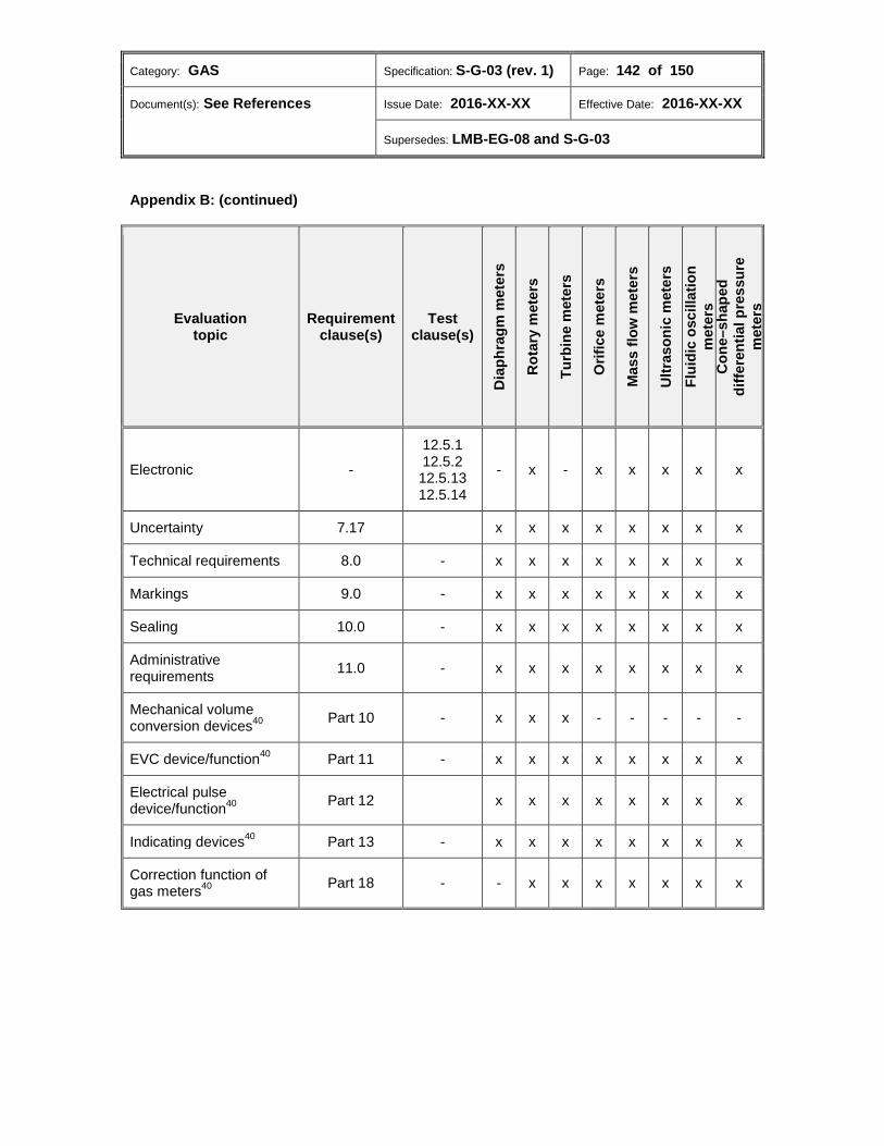
Category: GAS Specification: S-G-03 (rev. 1) Page: 142 of 150
Document(s): See References Issue Date: 2016-XX-XX Effective Date: 2016-XX-XX
Supersedes: LMB-EG-08 and S-G-03
Appendix B: (continued)
Evaluation topic
Requirement clause(s)
Test clause(s)
Dia
phra
gm m
eter
s
Rot
ary
met
ers
Turb
ine
met
ers
Orif
ice
met
ers
Mas
s flo
w m
eter
s
Ultr
ason
ic m
eter
s Fl
uidi
c os
cilla
tion
met
ers
Con
e–sh
aped
di
ffere
ntia
l pre
ssur
e m
eter
s
Electronic -
12.5.1 12.5.2 12.5.13 12.5.14
- x - x x x x x
Uncertainty 7.17 x x x x x x x x
Technical requirements 8.0 - x x x x x x x x
Markings 9.0 - x x x x x x x x
Sealing 10.0 - x x x x x x x x
Administrative requirements 11.0 - x x x x x x x x
Mechanical volume conversion devices40 Part 10 - x x x - - - - -
EVC device/function40 Part 11 - x x x x x x x x
Electrical pulse device/function40 Part 12 x x x x x x x x
Indicating devices40 Part 13 - x x x x x x x x
Correction function of gas meters40 Part 18 - - x x x x x x x
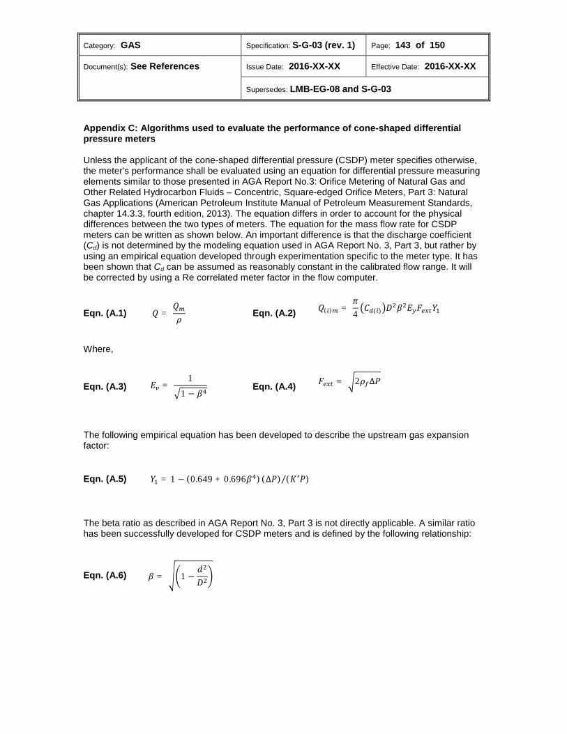
Category: GAS Specification: S-G-03 (rev. 1) Page: 143 of 150
Document(s): See References Issue Date: 2016-XX-XX Effective Date: 2016-XX-XX
Supersedes: LMB-EG-08 and S-G-03
Appendix C: Algorithms used to evaluate the performance of cone-shaped differential pressure meters Unless the applicant of the cone-shaped differential pressure (CSDP) meter specifies otherwise, the meter's performance shall be evaluated using an equation for differential pressure measuring elements similar to those presented in AGA Report No.3: Orifice Metering of Natural Gas and Other Related Hydrocarbon Fluids – Concentric, Square-edged Orifice Meters, Part 3: Natural Gas Applications (American Petroleum Institute Manual of Petroleum Measurement Standards, chapter 14.3.3, fourth edition, 2013). The equation differs in order to account for the physical differences between the two types of meters. The equation for the mass flow rate for CSDP meters can be written as shown below. An important difference is that the discharge coefficient (Cd) is not determined by the modeling equation used in AGA Report No. 3, Part 3, but rather by using an empirical equation developed through experimentation specific to the meter type. It has been shown that Cd can be assumed as reasonably constant in the calibrated flow range. It will be corrected by using a Re correlated meter factor in the flow computer.
Eqn. (A.1) 𝑄 = 𝑄𝑚
𝜌
Eqn. (A.2) 𝑄(𝑖)𝑚 =
𝜋4
�𝐶𝑑(𝑖)�𝐷2𝛽2𝐸𝑦𝐹𝑠𝑚𝑡𝑌1
Where,
Eqn. (A.3) 𝐸𝑣 = 1
�1 − 𝛽4
Eqn. (A.4) 𝐹𝑠𝑚𝑡 = �2𝜌𝑓∆𝑃
The following empirical equation has been developed to describe the upstream gas expansion factor:
Eqn. (A.5) 𝑌1 = 1 − (0.649 + 0.696𝛽4) (∆𝑃) (𝐾′𝑃)⁄
The beta ratio as described in AGA Report No. 3, Part 3 is not directly applicable. A similar ratio has been successfully developed for CSDP meters and is defined by the following relationship:
Eqn. (A.6) 𝛽 = ��1 −𝑑2
𝐷2�

Category: GAS Specification: S-G-03 (rev. 1) Page: 144 of 150
Document(s): See References Issue Date: 2016-XX-XX Effective Date: 2016-XX-XX
Supersedes: LMB-EG-08 and S-G-03
Use of data in flow computers Knowing, from a reference standard, the true mass flow rate at each of the prescribed test points (Qref(i)), Cd,(i) can be calculated using the following equation:
Eqn. (A.7) 𝐶𝑑,(𝑖) = 4𝑄𝑟𝑠𝑓,(𝑖)
(𝜋𝐷2𝛽2𝐸𝑣𝐹𝑠𝑚𝑡𝑌𝑙)
In the first method, once the values for Cd have been calculated, the values will be used to determine the relationship between Re and the meter factor (Mf(i)) at each test point. The Mf(i) values will then be programmed in the flow computer.
Eqn. (A.8) 𝑀𝑓 = 𝐶𝑑,𝑅𝑠
𝐶𝑑,𝑚𝑠𝑚𝑛
Eqn. (A.9) 𝑅𝑅 = 𝜌𝜌𝐷
𝜇
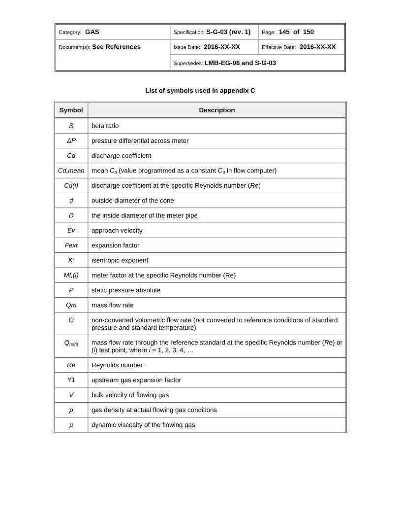
Category: GAS Specification: S-G-03 (rev. 1) Page: 145 of 150
Document(s): See References Issue Date: 2016-XX-XX Effective Date: 2016-XX-XX
Supersedes: LMB-EG-08 and S-G-03
List of symbols used in appendix C
Symbol Description
ß beta ratio
ΔP pressure differential across meter
Cd discharge coefficient
Cd,mean mean Cd (value programmed as a constant Cd in flow computer)
Cd(i) discharge coefficient at the specific Reynolds number (Re)
d outside diameter of the cone
D the inside diameter of the meter pipe
Ev approach velocity
Fext expansion factor
K’ isentropic exponent
Mf,(i) meter factor at the specific Reynolds number (Re)
P static pressure absolute
Qm mass flow rate
Q non-converted volumetric flow rate (not converted to reference conditions of standard pressure and standard temperature)
Qref(i) mass flow rate through the reference standard at the specific Reynolds number (Re) or (i) test point, where i = 1, 2, 3, 4, …
Re Reynolds number
Y1 upstream gas expansion factor
V bulk velocity of flowing gas
ρ gas density at actual flowing gas conditions
µ dynamic viscosity of the flowing gas
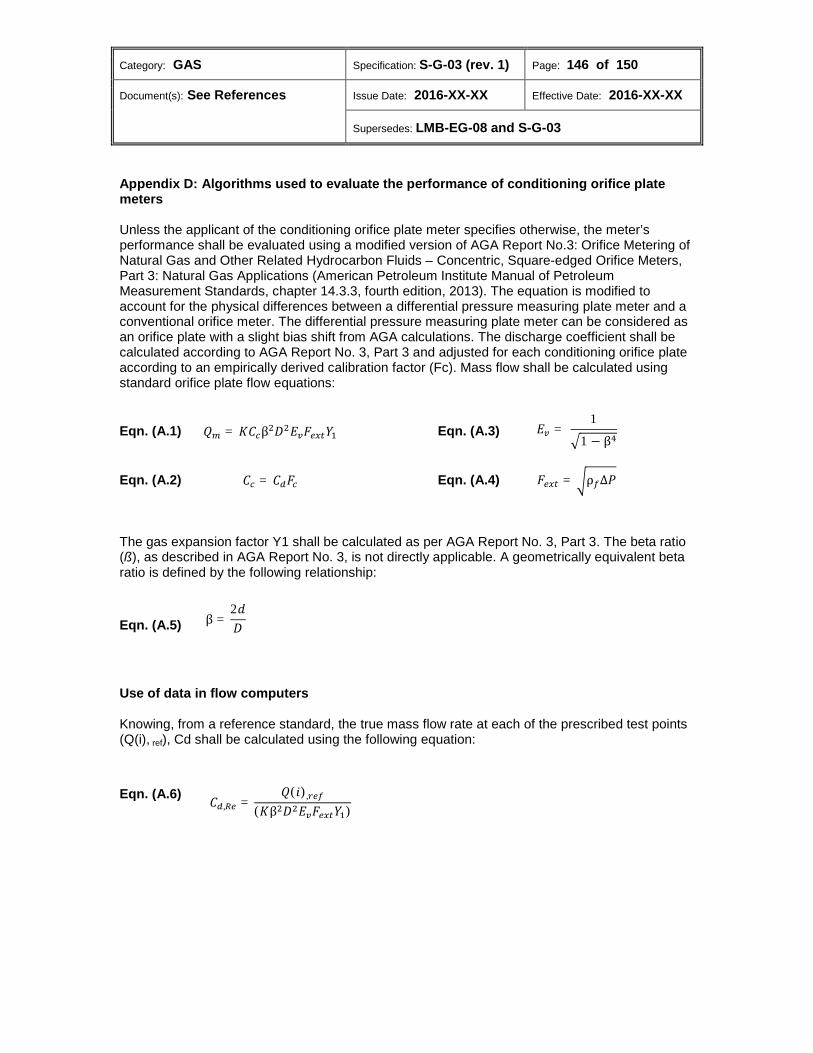
Category: GAS Specification: S-G-03 (rev. 1) Page: 146 of 150
Document(s): See References Issue Date: 2016-XX-XX Effective Date: 2016-XX-XX
Supersedes: LMB-EG-08 and S-G-03
Appendix D: Algorithms used to evaluate the performance of conditioning orifice plate meters Unless the applicant of the conditioning orifice plate meter specifies otherwise, the meter’s performance shall be evaluated using a modified version of AGA Report No.3: Orifice Metering of Natural Gas and Other Related Hydrocarbon Fluids – Concentric, Square-edged Orifice Meters, Part 3: Natural Gas Applications (American Petroleum Institute Manual of Petroleum Measurement Standards, chapter 14.3.3, fourth edition, 2013). The equation is modified to account for the physical differences between a differential pressure measuring plate meter and a conventional orifice meter. The differential pressure measuring plate meter can be considered as an orifice plate with a slight bias shift from AGA calculations. The discharge coefficient shall be calculated according to AGA Report No. 3, Part 3 and adjusted for each conditioning orifice plate according to an empirically derived calibration factor (Fc). Mass flow shall be calculated using standard orifice plate flow equations:
Eqn. (A.1) 𝑄𝑚 = 𝐾𝐶𝑐β2𝐷2𝐸𝑣𝐹𝑠𝑚𝑡𝑌1
Eqn. (A.3) 𝐸𝑣 = 1
�1 − β4
Eqn. (A.2) 𝐶𝑐 = 𝐶𝑑𝐹𝑐 Eqn. (A.4) 𝐹𝑠𝑚𝑡 = �ρ𝑓∆𝑃
The gas expansion factor Y1 shall be calculated as per AGA Report No. 3, Part 3. The beta ratio (ß), as described in AGA Report No. 3, is not directly applicable. A geometrically equivalent beta ratio is defined by the following relationship:
Eqn. (A.5) β =2𝑑𝐷
Use of data in flow computers Knowing, from a reference standard, the true mass flow rate at each of the prescribed test points (Q(i), ref), Cd shall be calculated using the following equation:
Eqn. (A.6)
𝐶𝑑,𝑅𝑠 =𝑄(𝑖),𝑟𝑠𝑓
(𝐾β2𝐷2𝐸𝑣𝐹𝑠𝑚𝑡𝑌1)
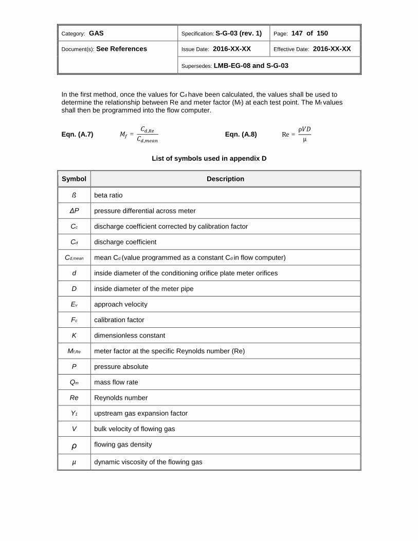
Category: GAS Specification: S-G-03 (rev. 1) Page: 147 of 150
Document(s): See References Issue Date: 2016-XX-XX Effective Date: 2016-XX-XX
Supersedes: LMB-EG-08 and S-G-03
In the first method, once the values for Cd have been calculated, the values shall be used to determine the relationship between Re and meter factor (Mf) at each test point. The Mf values shall then be programmed into the flow computer.
Eqn. (A.7) 𝑀𝑓 =𝐶𝑑,𝑅𝑠
𝐶𝑑,𝑚𝑠𝑚𝑛
Eqn. (A.8) Re =ρ𝜌𝐷
µ
List of symbols used in appendix D
Symbol Description
ß beta ratio
ΔP pressure differential across meter
Cc discharge coefficient corrected by calibration factor
Cd discharge coefficient
Cd,mean mean Cd (value programmed as a constant Cd in flow computer)
d inside diameter of the conditioning orifice plate meter orifices
D inside diameter of the meter pipe
Ev approach velocity
Fc calibration factor
K dimensionless constant
Mf,Re meter factor at the specific Reynolds number (Re)
P pressure absolute
Qm mass flow rate
Re Reynolds number
Y1 upstream gas expansion factor
V bulk velocity of flowing gas
ρ flowing gas density
µ dynamic viscosity of the flowing gas

Category: GAS Specification: S-G-03 (rev. 1) Page: 148 of 150
Document(s): See References Issue Date: 2016-XX-XX Effective Date: 2016-XX-XX
Supersedes: LMB-EG-08 and S-G-03
1 MC may conduct the same tests, audit the tests or conduct additional tests at any points within the range for which approval is sought. 2 Where conflict exists between these specifications and the above referenced documents, these specifications take precedence. 3 A flow computer is a calculator. 4 It is only applicable for positive displacement gas flow meters. 5 The term "intermediate means" is broad enough to include wire or wireless techniques for transmitting measurement data from the source electricity or gas meter. 6 It is declared/attested by the manufacturer. 7 This requirement refers to stationary operating conditions. This condition does not refer to the response of the gas meter to changed flow rates. 8 Any compatible electronic reading device loaded with the approved software/firmware is therefore considered to be an approved indicator, provided that obtaining the readings does not require breaking the security seal. 9 Rechargeable power sources are considered replaceable. 10 Alternatively, the markings may be prominently indicated either on the meter nameplate or be accessible via the device’s electronic display or output to an external device (by remote interrogation software) in a clear and unambiguous manner. 11 Alternatively, the markings may be prominently indicated either on the meter nameplate or be accessible via the device’s electronic display or output to an external device (by remote interrogation software) in a clear and unambiguous manner. 12 Alternatively, the markings may be prominently indicated either on the meter nameplate or be accessible via the device’s electronic display or output to an external device (by remote interrogation software) in a clear and unambiguous manner. 13 Alternatively, the markings may be prominently indicated either on the meter nameplate or be accessible via the device’s electronic display or output to an external device (by remote interrogation software) in a clear and unambiguous manner. 14 Alternatively, the markings may be prominently indicated either on the meter nameplate or be accessible via the device’s electronic display or output to an external device (by remote interrogation software) in a clear and unambiguous manner. 15 Alternatively, the markings may be prominently indicated either on the meter nameplate or be accessible via the device’s electronic display or output to an external device (by remote interrogation software) in a clear and unambiguous manner.

Category: GAS Specification: S-G-03 (rev. 1) Page: 149 of 150
Document(s): See References Issue Date: 2016-XX-XX Effective Date: 2016-XX-XX
Supersedes: LMB-EG-08 and S-G-03
16 Alternatively, the markings may be prominently indicated either on the meter nameplate or be accessible via the device’s electronic display or output to an external device (by remote interrogation software) in a clear and unambiguous manner. 17 Alternatively, the markings may be prominently indicated either on the meter nameplate or be accessible via the device’s electronic display or output to an external device (by remote interrogation software) in a clear and unambiguous manner. 18 Electronic ancillary devices may have the capacity per revolution of the input shaft accessible via their indicator or by remote interrogation software. 19 The test medium is normally natural gas. 20 For gas meters which are intended to be used at high pressures, this test may be performed at the lowest operating pressure. 21 In addition, meters may be tested at any pressure up to the maximum operating pressure. 22 In addition, meters may be tested at any pressure up to the maximum operating pressure. 23 These specifications do not cover the equipment used in the determination of the pressures, temperatures and other variances which must be known for the accurate measurement of gas quantities. 24 If the Qmin declared by an approval applicant is less than 0.1 Qmax, use Qmin. If this Qmin value is not less than 0.1 Qmax, use 0.1 Qmax. 25 Such devices may be incorporated entirely within a meter, be of a modular nature or be intended for use as an ancillary attachment. 26
a. In some cases, the minimum value of certain inputs or programmable constants may be zero. In this event, the tests above shall be carried out with the value set at 10 percent of the range of the input or programmable constant instead of the minimum value.
b. For flowing gas pressure input, the minimum will be considered to be 25% of the maximum pressure. For differential pressure input, the minimum will be considered to be 10% of the differential pressure span.
c. The median value of the range or span shall correspond to 50%. 27
a. In some cases, the minimum value of certain inputs or programmable constants may be zero. In this event, the tests above shall be carried out with the value set at 10 percent of the range of the input or programmable constant instead of the minimum value.
b. For flowing gas pressure input, the minimum will be considered to be 25% of the maximum pressure. For differential pressure input, the minimum will be considered to be 10% of the differential pressure span.
c. The median value of the range or span shall correspond to 50%.
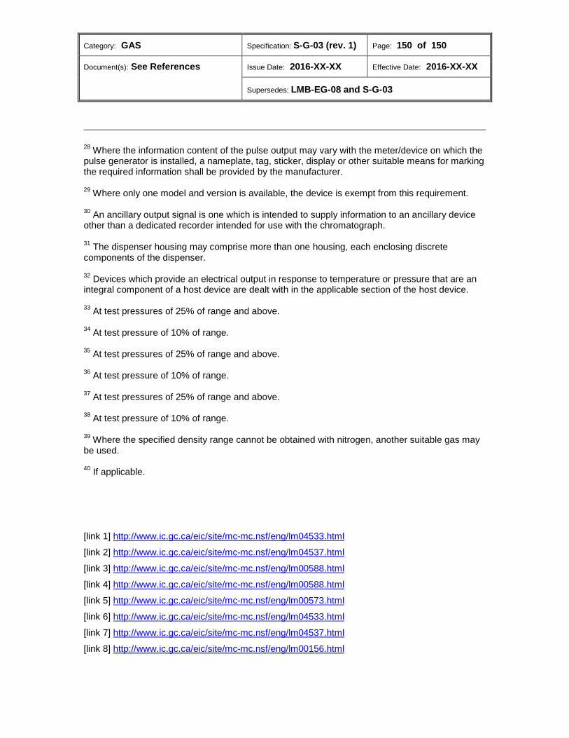
Category: GAS Specification: S-G-03 (rev. 1) Page: 150 of 150
Document(s): See References Issue Date: 2016-XX-XX Effective Date: 2016-XX-XX
Supersedes: LMB-EG-08 and S-G-03
28 Where the information content of the pulse output may vary with the meter/device on which the pulse generator is installed, a nameplate, tag, sticker, display or other suitable means for marking the required information shall be provided by the manufacturer. 29 Where only one model and version is available, the device is exempt from this requirement. 30 An ancillary output signal is one which is intended to supply information to an ancillary device other than a dedicated recorder intended for use with the chromatograph. 31 The dispenser housing may comprise more than one housing, each enclosing discrete components of the dispenser. 32 Devices which provide an electrical output in response to temperature or pressure that are an integral component of a host device are dealt with in the applicable section of the host device. 33 At test pressures of 25% of range and above. 34 At test pressure of 10% of range. 35 At test pressures of 25% of range and above. 36 At test pressure of 10% of range. 37 At test pressures of 25% of range and above. 38 At test pressure of 10% of range. 39 Where the specified density range cannot be obtained with nitrogen, another suitable gas may be used. 40 If applicable. [link 1] http://www.ic.gc.ca/eic/site/mc-mc.nsf/eng/lm04533.html
[link 2] http://www.ic.gc.ca/eic/site/mc-mc.nsf/eng/lm04537.html
[link 3] http://www.ic.gc.ca/eic/site/mc-mc.nsf/eng/lm00588.html
[link 4] http://www.ic.gc.ca/eic/site/mc-mc.nsf/eng/lm00588.html
[link 5] http://www.ic.gc.ca/eic/site/mc-mc.nsf/eng/lm00573.html
[link 6] http://www.ic.gc.ca/eic/site/mc-mc.nsf/eng/lm04533.html
[link 7] http://www.ic.gc.ca/eic/site/mc-mc.nsf/eng/lm04537.html
[link 8] http://www.ic.gc.ca/eic/site/mc-mc.nsf/eng/lm00156.html