Embed Size (px)
Citation preview
Reference Manual 00809-0100-4530, Rev AAJune 2007
Rosemount 5300 SeriesHigh Performance Guided Wave Radar
www.rosemount.com

Reference Manual 00809-0100-4530, Rev AAJune 2007 Rosemount 5300 Series
Rosemount 5300 Series
Guided Wave Radar Level and Interface TransmittersCover Photo: 5300_coverphoto.tif
NOTICE
Read this manual before working with the product. For personal and system safety, and for optimum product performance, make sure you thoroughly understand the contents before installing, using, or maintaining this product.
Within the United States, Rosemount Inc. has two toll-free assistance numbers.
Customer Central: 1-800-999-9307(7:00 a.m. to 7:00 p.m. CST)Technical support, quoting, and order-related questions.
North American Response Center:Equipment service needs.
1-800-654-7768 (24 hours a day � Includes Canada)
For equipment service or support needs outside the United States, contact your local Rosemount representative.
The products described in this document are NOT designed for nuclear-qualified applications.
Using non-nuclear qualified products in applications that require nuclear-qualified hardware or products may cause inaccurate readings.
For information on Rosemount nuclear-qualified products, contact your local Rosemount Sales Representative.
This product is designed to meet FCC and R&TTE requirements for a non-intentional radiator. It does not require any licensing whatsoever and has no tank restrictions associated with telecommunications issues.
This device complies with part 15 of the FCC rules. Operation is subject to the following two conditions: (1) This device may not cause harmful interference, and (2) this device must accept any interference received, including interference that may cause undesired operation.
www.rosemount.com

Reference Manual 00809-0100-4530, Rev AAJune 2007 Rosemount 5300 Series
Table of Contents
SECTION 1IntroductionSafety Messages . . . . . . . . . . . . . . . . . . . . . . . . . . . . . . . . . . . . . . . . . 1-1Manual Overview . . . . . . . . . . . . . . . . . . . . . . . . . . . . . . . . . . . . . . . . . 1-2Service Support . . . . . . . . . . . . . . . . . . . . . . . . . . . . . . . . . . . . . . . . . . 1-3
SECTION 2Transmitter Overview
Theory of Operation. . . . . . . . . . . . . . . . . . . . . . . . . . . . . . . . . . . . . . . 2-1Applications . . . . . . . . . . . . . . . . . . . . . . . . . . . . . . . . . . . . . . . . . . . . . 2-2Components of the Transmitter . . . . . . . . . . . . . . . . . . . . . . . . . . . . . . 2-5System Architecture. . . . . . . . . . . . . . . . . . . . . . . . . . . . . . . . . . . . . . . 2-6Probe Selection Guide. . . . . . . . . . . . . . . . . . . . . . . . . . . . . . . . . . . . . 2-8
Transition Zones. . . . . . . . . . . . . . . . . . . . . . . . . . . . . . . . . . . . . . . 2-9Process Characteristics . . . . . . . . . . . . . . . . . . . . . . . . . . . . . . . . . . . 2-10
Coating . . . . . . . . . . . . . . . . . . . . . . . . . . . . . . . . . . . . . . . . . . . . . 2-10Bridging . . . . . . . . . . . . . . . . . . . . . . . . . . . . . . . . . . . . . . . . . . . . 2-10Foam . . . . . . . . . . . . . . . . . . . . . . . . . . . . . . . . . . . . . . . . . . . . . . 2-10Vapor . . . . . . . . . . . . . . . . . . . . . . . . . . . . . . . . . . . . . . . . . . . . . . 2-10Measuring Range . . . . . . . . . . . . . . . . . . . . . . . . . . . . . . . . . . . . . 2-11Interface . . . . . . . . . . . . . . . . . . . . . . . . . . . . . . . . . . . . . . . . . . . . 2-11
Vessel Characteristics . . . . . . . . . . . . . . . . . . . . . . . . . . . . . . . . . . . . 2-13Heating Coils, Agitators . . . . . . . . . . . . . . . . . . . . . . . . . . . . . . . . 2-13Tank Shape . . . . . . . . . . . . . . . . . . . . . . . . . . . . . . . . . . . . . . . . . 2-13
Installation Procedure . . . . . . . . . . . . . . . . . . . . . . . . . . . . . . . . . . . . 2-14
SECTION 3Mechanical Installation
Safety messages . . . . . . . . . . . . . . . . . . . . . . . . . . . . . . . . . . . . . . . . . 3-1Mounting Considerations . . . . . . . . . . . . . . . . . . . . . . . . . . . . . . . . . . . 3-2
Process Connection . . . . . . . . . . . . . . . . . . . . . . . . . . . . . . . . . . . . 3-2Installation of Single Lead Probes in Non-metallic Vessels . . . . . . 3-4Installation in Concrete Silos . . . . . . . . . . . . . . . . . . . . . . . . . . . . . 3-4Considerations for Solid Applications . . . . . . . . . . . . . . . . . . . . . . . 3-5Mounting in Still pipes/by-pass pipes . . . . . . . . . . . . . . . . . . . . . . . 3-6Free Space . . . . . . . . . . . . . . . . . . . . . . . . . . . . . . . . . . . . . . . . . . . 3-7Recommended Mounting Position for Liquids . . . . . . . . . . . . . . . . 3-8Recommended Mounting for Solids . . . . . . . . . . . . . . . . . . . . . . . . 3-9Insulated Tanks . . . . . . . . . . . . . . . . . . . . . . . . . . . . . . . . . . . . . . 3-10
Mounting . . . . . . . . . . . . . . . . . . . . . . . . . . . . . . . . . . . . . . . . . . . . . . 3-11Flange Connection . . . . . . . . . . . . . . . . . . . . . . . . . . . . . . . . . . . . 3-11Threaded Connection . . . . . . . . . . . . . . . . . . . . . . . . . . . . . . . . . . 3-12Shortening the Probe . . . . . . . . . . . . . . . . . . . . . . . . . . . . . . . . . . 3-13Anchoring . . . . . . . . . . . . . . . . . . . . . . . . . . . . . . . . . . . . . . . . . . . 3-16Mounting a Centering Disc for Pipe Installations . . . . . . . . . . . . . 3-19
SECTION 4Electrical Installation
Safety messages . . . . . . . . . . . . . . . . . . . . . . . . . . . . . . . . . . . . . . . . . 4-1Cable/conduit entries . . . . . . . . . . . . . . . . . . . . . . . . . . . . . . . . . . . . . . 4-3Grounding . . . . . . . . . . . . . . . . . . . . . . . . . . . . . . . . . . . . . . . . . . . . . . 4-3
www.rosemount.com
Reference Manual00809-0100-4530, Rev AA
June 2007Rosemount 5300 Series
Cable Selection . . . . . . . . . . . . . . . . . . . . . . . . . . . . . . . . . . . . . . . . . . 4-3Hazardous Areas . . . . . . . . . . . . . . . . . . . . . . . . . . . . . . . . . . . . . . . . . 4-3HART. . . . . . . . . . . . . . . . . . . . . . . . . . . . . . . . . . . . . . . . . . . . . . . . . . 4-4
Power Requirements . . . . . . . . . . . . . . . . . . . . . . . . . . . . . . . . . . . 4-4Maximum Loop Resistance . . . . . . . . . . . . . . . . . . . . . . . . . . . . . . 4-4Connecting the Transmitter . . . . . . . . . . . . . . . . . . . . . . . . . . . . . . 4-5Non-Intrinsically Safe Output . . . . . . . . . . . . . . . . . . . . . . . . . . . . . 4-6Intrinsically Safe Output . . . . . . . . . . . . . . . . . . . . . . . . . . . . . . . . . 4-7
FOUNDATION� Fieldbus . . . . . . . . . . . . . . . . . . . . . . . . . . . . . . . . . . . . 4-8Power Requirements . . . . . . . . . . . . . . . . . . . . . . . . . . . . . . . . . . . 4-8Connecting the Transmitter . . . . . . . . . . . . . . . . . . . . . . . . . . . . . . 4-8Non-Intrinsically Safe Output . . . . . . . . . . . . . . . . . . . . . . . . . . . . 4-11Intrinsically Safe Output . . . . . . . . . . . . . . . . . . . . . . . . . . . . . . . . 4-12
Optional Devices . . . . . . . . . . . . . . . . . . . . . . . . . . . . . . . . . . . . . . . . 4-13Tri-Loop HART to analog converter . . . . . . . . . . . . . . . . . . . . . . . 4-13751 Field Signal Indicator . . . . . . . . . . . . . . . . . . . . . . . . . . . . . . . 4-14
SECTION 5Configuration
Safety messages . . . . . . . . . . . . . . . . . . . . . . . . . . . . . . . . . . . . . . . . . 5-1Overview . . . . . . . . . . . . . . . . . . . . . . . . . . . . . . . . . . . . . . . . . . . . . . . 5-2
Basic Configuration . . . . . . . . . . . . . . . . . . . . . . . . . . . . . . . . . . . . 5-2Echo Tuning . . . . . . . . . . . . . . . . . . . . . . . . . . . . . . . . . . . . . . . . . . 5-2LCD Configuration . . . . . . . . . . . . . . . . . . . . . . . . . . . . . . . . . . . . . 5-2Advanced Configuration . . . . . . . . . . . . . . . . . . . . . . . . . . . . . . . . . 5-2Configuration Tools . . . . . . . . . . . . . . . . . . . . . . . . . . . . . . . . . . . . 5-2
Basic Configuration Parameters . . . . . . . . . . . . . . . . . . . . . . . . . . . . . 5-3Measurement Units . . . . . . . . . . . . . . . . . . . . . . . . . . . . . . . . . . . . 5-3Tank and Probe Geometry . . . . . . . . . . . . . . . . . . . . . . . . . . . . . . . 5-3Tank Environment . . . . . . . . . . . . . . . . . . . . . . . . . . . . . . . . . . . . . 5-5Volume Configuration . . . . . . . . . . . . . . . . . . . . . . . . . . . . . . . . . . . 5-6Analog Output (HART) . . . . . . . . . . . . . . . . . . . . . . . . . . . . . . . . . . 5-8
Basic Configuration using a 375 Field Communicator. . . . . . . . . . . . 5-10Basic Configuration Using Rosemount Radar Master . . . . . . . . . . . . 5-12
System Requirements . . . . . . . . . . . . . . . . . . . . . . . . . . . . . . . . . 5-12Help In RRM . . . . . . . . . . . . . . . . . . . . . . . . . . . . . . . . . . . . . . . . . 5-12Installing the RRM software for HART communication . . . . . . . . 5-13Specifying the COM Port . . . . . . . . . . . . . . . . . . . . . . . . . . . . . . . 5-14To set the COM port buffers . . . . . . . . . . . . . . . . . . . . . . . . . . . . . 5-14Installing the RRM Software for Foundation Fieldbus . . . . . . . . . 5-15Specifying Measurement Units. . . . . . . . . . . . . . . . . . . . . . . . . . . 5-16Using the Setup Functions . . . . . . . . . . . . . . . . . . . . . . . . . . . . . . 5-17Guided Setup . . . . . . . . . . . . . . . . . . . . . . . . . . . . . . . . . . . . . . . . 5-18Device Properties . . . . . . . . . . . . . . . . . . . . . . . . . . . . . . . . . . . . . 5-19General Information . . . . . . . . . . . . . . . . . . . . . . . . . . . . . . . . . . . 5-19Probe . . . . . . . . . . . . . . . . . . . . . . . . . . . . . . . . . . . . . . . . . . . . . . 5-20Geometry . . . . . . . . . . . . . . . . . . . . . . . . . . . . . . . . . . . . . . . . . . . 5-21Tank Environment . . . . . . . . . . . . . . . . . . . . . . . . . . . . . . . . . . . . 5-22Volume . . . . . . . . . . . . . . . . . . . . . . . . . . . . . . . . . . . . . . . . . . . . . 5-24Analog Output (HART) . . . . . . . . . . . . . . . . . . . . . . . . . . . . . . . . . 5-26Finish Configuration Wizard . . . . . . . . . . . . . . . . . . . . . . . . . . . . . 5-27Restart the Transmitter. . . . . . . . . . . . . . . . . . . . . . . . . . . . . . . . . 5-27View Measured Values. . . . . . . . . . . . . . . . . . . . . . . . . . . . . . . . . 5-28Backup . . . . . . . . . . . . . . . . . . . . . . . . . . . . . . . . . . . . . . . . . . . . . 5-28
TOC-2
Reference Manual 00809-0100-4530, Rev AAJune 2007 Rosemount 5300 Series
Basic Configuration Using AMS Suite (HART) . . . . . . . . . . . . . . . . . 5-29Basic Configuration Using DeltaV . . . . . . . . . . . . . . . . . . . . . . . . . . . 5-30FOUNDATION Fieldbus Overview. . . . . . . . . . . . . . . . . . . . . . . . . . . . . 5-35
Assigning Device Tag and Node Address . . . . . . . . . . . . . . . . . . 5-35Foundation Fieldbus Block Operation . . . . . . . . . . . . . . . . . . . . . 5-36
Configure the AI Block . . . . . . . . . . . . . . . . . . . . . . . . . . . . . . . . . . . . 5-38Application Example 1 . . . . . . . . . . . . . . . . . . . . . . . . . . . . . . . . . 5-41Application Example 2 . . . . . . . . . . . . . . . . . . . . . . . . . . . . . . . . . 5-42Application Example 3 . . . . . . . . . . . . . . . . . . . . . . . . . . . . . . . . . 5-43
TriLoop HART to Analog Converter. . . . . . . . . . . . . . . . . . . . . . . . . . 5-44HART Multi-drop Configuration . . . . . . . . . . . . . . . . . . . . . . . . . . . . . 5-46
SECTION 6Operation
Safety Messages . . . . . . . . . . . . . . . . . . . . . . . . . . . . . . . . . . . . . . . . . 6-1Viewing Measurement Data. . . . . . . . . . . . . . . . . . . . . . . . . . . . . . . . . 6-2
Using the Display Panel . . . . . . . . . . . . . . . . . . . . . . . . . . . . . . . . . 6-2Specifying Display Panel Variables . . . . . . . . . . . . . . . . . . . . . . . . 6-3Viewing Measurement Data in RRM . . . . . . . . . . . . . . . . . . . . . . . 6-7Viewing Measurement Data in AMS Suite . . . . . . . . . . . . . . . . . . . 6-8Viewing Measurement Data in DeltaV . . . . . . . . . . . . . . . . . . . . . . 6-9
SECTION 7Service and Troubleshooting
Safety messages . . . . . . . . . . . . . . . . . . . . . . . . . . . . . . . . . . . . . . . . . 7-1Analyzing the Measurement Signal . . . . . . . . . . . . . . . . . . . . . . . . . . . 7-3Surface Pulse Not Found. . . . . . . . . . . . . . . . . . . . . . . . . . . . . . . . . . . 7-5
Probe End Projection . . . . . . . . . . . . . . . . . . . . . . . . . . . . . . . . . . . 7-7Disturbance Echo Handling . . . . . . . . . . . . . . . . . . . . . . . . . . . . . . . . . 7-8
Amplitude Threshold Curve . . . . . . . . . . . . . . . . . . . . . . . . . . . . . . 7-8Disturbances at the Top of the Tank . . . . . . . . . . . . . . . . . . . . . . . 7-8
Interface Pulse not Found . . . . . . . . . . . . . . . . . . . . . . . . . . . . . . . . . . 7-9Using the Echo Curve Analyzer. . . . . . . . . . . . . . . . . . . . . . . . . . . . . 7-11
Using the Rosemount Radar Master . . . . . . . . . . . . . . . . . . . . . . 7-11The Configuration Mode Tab . . . . . . . . . . . . . . . . . . . . . . . . . . . . 7-12The View/Record ModeTab . . . . . . . . . . . . . . . . . . . . . . . . . . . . . 7-13The File ModeTab . . . . . . . . . . . . . . . . . . . . . . . . . . . . . . . . . . . . 7-13Using the Echo Curve Analyzer with a 375 Field Communicator . 7-14
Interface Measurements with Fully Submerged Probes . . . . . . . . . . 7-16Analog Output Calibration . . . . . . . . . . . . . . . . . . . . . . . . . . . . . . . . . 7-17Level and Distance Calibration . . . . . . . . . . . . . . . . . . . . . . . . . . . . . 7-18Logging Measurement Data . . . . . . . . . . . . . . . . . . . . . . . . . . . . . . . 7-19Backing Up the Transmitter Configuration. . . . . . . . . . . . . . . . . . . . . 7-20Configuration Report . . . . . . . . . . . . . . . . . . . . . . . . . . . . . . . . . . . . . 7-21Reset to Factory Settings . . . . . . . . . . . . . . . . . . . . . . . . . . . . . . . . . 7-22Diagnostics . . . . . . . . . . . . . . . . . . . . . . . . . . . . . . . . . . . . . . . . . . . . 7-23Using the Simulation Mode . . . . . . . . . . . . . . . . . . . . . . . . . . . . . . . . 7-25Write Protecting a Transmitter . . . . . . . . . . . . . . . . . . . . . . . . . . . . . . 7-26Enter Service Mode in RRM . . . . . . . . . . . . . . . . . . . . . . . . . . . . . . . 7-26Viewing Input and Holding Registers. . . . . . . . . . . . . . . . . . . . . . . . . 7-27Removing the Transmitter Head . . . . . . . . . . . . . . . . . . . . . . . . . . . . 7-28Changing the Probe. . . . . . . . . . . . . . . . . . . . . . . . . . . . . . . . . . . . . . 7-29Diagnostic Messages. . . . . . . . . . . . . . . . . . . . . . . . . . . . . . . . . . . . . 7-30
Troubleshooting . . . . . . . . . . . . . . . . . . . . . . . . . . . . . . . . . . . . . . 7-30Device Status . . . . . . . . . . . . . . . . . . . . . . . . . . . . . . . . . . . . . . . . 7-32Errors . . . . . . . . . . . . . . . . . . . . . . . . . . . . . . . . . . . . . . . . . . . . . . 7-33
TOC-3
Reference Manual00809-0100-4530, Rev AA
June 2007Rosemount 5300 Series
Warnings . . . . . . . . . . . . . . . . . . . . . . . . . . . . . . . . . . . . . . . . . . . 7-34Measurement Status . . . . . . . . . . . . . . . . . . . . . . . . . . . . . . . . . . 7-35Interface Status . . . . . . . . . . . . . . . . . . . . . . . . . . . . . . . . . . . . . . 7-36Volume Calculation Status . . . . . . . . . . . . . . . . . . . . . . . . . . . . . . 7-36Analog Output Status . . . . . . . . . . . . . . . . . . . . . . . . . . . . . . . . . . 7-37
LED Error Messages . . . . . . . . . . . . . . . . . . . . . . . . . . . . . . . . . . . . . 7-38Foundation Fieldbus Error Messages . . . . . . . . . . . . . . . . . . . . . . . . 7-39
Resource Block . . . . . . . . . . . . . . . . . . . . . . . . . . . . . . . . . . . . . . 7-39Transducer Block . . . . . . . . . . . . . . . . . . . . . . . . . . . . . . . . . . . . . 7-40Analog Input (AI) Function Block . . . . . . . . . . . . . . . . . . . . . . . . . 7-40
APPENDIX AReference Data
Specifications. . . . . . . . . . . . . . . . . . . . . . . . . . . . . . . . . . . . . . . . . . . .A-1Process Temperature and Pressure Rating . . . . . . . . . . . . . . . . . .A-4Ambient Temperature. . . . . . . . . . . . . . . . . . . . . . . . . . . . . . . . . . .A-7
Dimensional drawings . . . . . . . . . . . . . . . . . . . . . . . . . . . . . . . . . . . . .A-8Ordering Information . . . . . . . . . . . . . . . . . . . . . . . . . . . . . . . . . . . . .A-16Spare Parts . . . . . . . . . . . . . . . . . . . . . . . . . . . . . . . . . . . . . . . . . . . .A-23
APPENDIX BProduct Certifications
Safety messages . . . . . . . . . . . . . . . . . . . . . . . . . . . . . . . . . . . . . . . . .B-1EU Conformity . . . . . . . . . . . . . . . . . . . . . . . . . . . . . . . . . . . . . . . . . . .B-2European ATEX Directive Information. . . . . . . . . . . . . . . . . . . . . . . . .B-3
Intrinsic Safety . . . . . . . . . . . . . . . . . . . . . . . . . . . . . . . . . . . . . . . .B-3Flameproof . . . . . . . . . . . . . . . . . . . . . . . . . . . . . . . . . . . . . . . . . . .B-6
Factory Mutual (FM) Approvals . . . . . . . . . . . . . . . . . . . . . . . . . . . . . .B-8Intrinsic Safety . . . . . . . . . . . . . . . . . . . . . . . . . . . . . . . . . . . . . . . .B-8Explosion Proof . . . . . . . . . . . . . . . . . . . . . . . . . . . . . . . . . . . . . .B-10
Canadian Standards Association (CSA) Approval. . . . . . . . . . . . . . .B-11Intrinsic Safety . . . . . . . . . . . . . . . . . . . . . . . . . . . . . . . . . . . . . . .B-11Explosion Proof . . . . . . . . . . . . . . . . . . . . . . . . . . . . . . . . . . . . . .B-13
IECEx Approval . . . . . . . . . . . . . . . . . . . . . . . . . . . . . . . . . . . . . . . . .B-14Intrinsic Safety . . . . . . . . . . . . . . . . . . . . . . . . . . . . . . . . . . . . . . .B-14Flameproof . . . . . . . . . . . . . . . . . . . . . . . . . . . . . . . . . . . . . . . . . .B-17
Combination Approvals . . . . . . . . . . . . . . . . . . . . . . . . . . . . . . . . . . .B-19Approval Drawings. . . . . . . . . . . . . . . . . . . . . . . . . . . . . . . . . . . . . . .B-19
APPENDIX CAdvanced Configuration
Safety messages . . . . . . . . . . . . . . . . . . . . . . . . . . . . . . . . . . . . . . . . .C-1User defined Upper Reference Point. . . . . . . . . . . . . . . . . . . . . . . . . .C-3Handling of Disturbances from Nozzle . . . . . . . . . . . . . . . . . . . . . . . .C-4Threshold Settings. . . . . . . . . . . . . . . . . . . . . . . . . . . . . . . . . . . . . . . .C-6Probe End Projection. . . . . . . . . . . . . . . . . . . . . . . . . . . . . . . . . . . . . .C-8Dielectric Constant Settings. . . . . . . . . . . . . . . . . . . . . . . . . . . . . . . .C-10
Vapor . . . . . . . . . . . . . . . . . . . . . . . . . . . . . . . . . . . . . . . . . . . . . .C-10Lower Product . . . . . . . . . . . . . . . . . . . . . . . . . . . . . . . . . . . . . . .C-10
APPENDIX DLevel Transducer Block
Overview . . . . . . . . . . . . . . . . . . . . . . . . . . . . . . . . . . . . . . . . . . . . . . .D-1Definition. . . . . . . . . . . . . . . . . . . . . . . . . . . . . . . . . . . . . . . . . . . . .D-1Channel Definitions . . . . . . . . . . . . . . . . . . . . . . . . . . . . . . . . . . . .D-2
Parameters and Descriptions . . . . . . . . . . . . . . . . . . . . . . . . . . . . . . .D-2Supported Units . . . . . . . . . . . . . . . . . . . . . . . . . . . . . . . . . . . . . . . . . .D-7
Unit Codes . . . . . . . . . . . . . . . . . . . . . . . . . . . . . . . . . . . . . . . . . . .D-7Diagnostics Device Errors . . . . . . . . . . . . . . . . . . . . . . . . . . . . . . . . . .D-8
TOC-4
Reference Manual 00809-0100-4530, Rev AAJune 2007 Rosemount 5300 Series
APPENDIX ERegister Transducer Block
Overview . . . . . . . . . . . . . . . . . . . . . . . . . . . . . . . . . . . . . . . . . . . . . . .E-1Register Access Transducer Block Parameters . . . . . . . . . . . . . . .E-1
APPENDIX FAdvanced Configuration Transducer Block
Overview . . . . . . . . . . . . . . . . . . . . . . . . . . . . . . . . . . . . . . . . . . . . . . . F-1Advanced Configuration Transducer Block Parameters. . . . . . . . . F-1
APPENDIX GResource Transducer Block
Overview . . . . . . . . . . . . . . . . . . . . . . . . . . . . . . . . . . . . . . . . . . . . . . .G-1Parameters and Descriptions . . . . . . . . . . . . . . . . . . . . . . . . . . . . . . .G-1
PlantWeb� Alerts . . . . . . . . . . . . . . . . . . . . . . . . . . . . . . . . . . . . . .G-5Alarm Priority . . . . . . . . . . . . . . . . . . . . . . . . . . . . . . . . . . . . . . . . .G-7Process Alarms . . . . . . . . . . . . . . . . . . . . . . . . . . . . . . . . . . . . . . .G-7Recommended Actions for PlantWeb Alerts . . . . . . . . . . . . . . . . .G-8
APPENDIX HAnalog-Input Block
Simulation . . . . . . . . . . . . . . . . . . . . . . . . . . . . . . . . . . . . . . . . . . . . . .H-3Damping . . . . . . . . . . . . . . . . . . . . . . . . . . . . . . . . . . . . . . . . . . . . . . .H-4Signal Conversion . . . . . . . . . . . . . . . . . . . . . . . . . . . . . . . . . . . . . . . .H-5Block Errors . . . . . . . . . . . . . . . . . . . . . . . . . . . . . . . . . . . . . . . . . . . . .H-6Modes . . . . . . . . . . . . . . . . . . . . . . . . . . . . . . . . . . . . . . . . . . . . . . . . .H-6Alarm Detection . . . . . . . . . . . . . . . . . . . . . . . . . . . . . . . . . . . . . . . . . .H-7
Status Handling . . . . . . . . . . . . . . . . . . . . . . . . . . . . . . . . . . . . . . .H-8Advanced Features . . . . . . . . . . . . . . . . . . . . . . . . . . . . . . . . . . . . . . .H-8Configure the AI Block . . . . . . . . . . . . . . . . . . . . . . . . . . . . . . . . . . . . .H-9
TOC-5

Reference Manual00809-0100-4530, Rev AA
June 2007Rosemount 5300 Series
TOC-6
Reference Manual 00809-0100-4530, Rev AAJune 2007 Rosemount 5300 Series
Section 1 Introduction
Safety Messages . . . . . . . . . . . . . . . . . . . . . . . . . . . . . . . . . page 1-1Manual Overview . . . . . . . . . . . . . . . . . . . . . . . . . . . . . . . . page 1-2Service Support . . . . . . . . . . . . . . . . . . . . . . . . . . . . . . . . . page 1-3
SAFETY MESSAGES Procedures and instructions in this manual may require special precautions to ensure the safety of the personnel performing the operations. Information that raises potential safety issues is indicated by a warning symbol ( ). Refer to the safety messages listed at the beginning of each section before performing an operation preceded by this symbol.
Failure to follow these installation guidelines could result in death or serious injury.
� Make sure only qualified personnel perform the installation.
� Use the equipment only as specified in this manual. Failure to do so may impair the protection provided by the equipment.
Explosions could result in death or serious injury.� Verify that the operating environment of the transmitter is consistent with the
appropriate hazardous locations certifications.
� Before connecting a HART®-based communicator in an explosive atmosphere, make sure the instruments in the loop are installed in accordance with intrinsically safe or non-incendive field wiring practices.
Electrical shock could cause death or serious injury.� Use extreme caution when making contact with the leads and terminals.
Any substitution of non-recognized parts may jeopardize safety. Repair, e.g. substitution of components etc., may also jeopardize safety and is under no circumstances allowed.
www.rosemount.com
Reference Manual00809-0100-4530, Rev AA
June 2007Rosemount 5300 Series
MANUAL OVERVIEW This manual provides installation, configuration and maintenance information for the Rosemount 3300 Series Radar Transmitter.
Section 2: Transmitter Overview� Theory of Operation� Description of the transmitter� Process and vessel characteristics
Section 3: Mechanical Installation� Mounting considerations� Mounting
Section 4: Electrical Installation� Grounding� Cable selection� Power requirements� Wiring� Optional devices
Section 5: Configuration� Basic configuration� Configuration using the 375 Field Communicator� Configuration using the RRM software� Configuration using AMS Suite� Configuration using DeltaV� Foundation Fieldbus
Section 6: Operation� Viewing measurement data� Display functionality� Error messages
Section 7: Service and Troubleshooting� Service functions� Diagnostic messages
Appendix A: Reference Data� Specifications� Ordering Information
Appendix B: Product Certifications� Labels� European ATEX Directive information� FM approvals� CSA approvals� Approval drawings
1-2
Reference Manual 00809-0100-4530, Rev AAJune 2007 Rosemount 5300 Series
Appendix C: Advanced Configuration� Advanced Tank Geometry� Advanced Transmitter Configuration
Appendix D: Level Transducer BlockDescribes the operation and parameters of the Level transducer block.
Appendix E: Register Transducer BlockDescribes the operation and parameters of the Register transducer block.
Appendix F: Advanced Configuration Transducer BlockDescribes the operation and parameters of the Advanced Configuration transducer block.
Appendix G: Resource Transducer BlockDescribes the operation and parameters of the Resource transducer block.
Appendix H: Analog-Input Transducer BlockDescribes the operation and parameters of the Analog Input transducer block.
SERVICE SUPPORT To expedite the return process outside of the United States, contact the nearest Rosemount representative.
Within the United States, call the Rosemount National Response Center using the 1-800-654-RSMT (7768) toll-free number. This center, available 24 hours a day, will assist you with any needed information or materials.
The center will ask for product model and serial numbers, and will provide a Return Material Authorization (RMA) number. The center will also ask for the process material to which the product was last exposed.
Rosemount National Response Center representatives will explain the additional information and procedures necessary to return goods exposed to hazardous substance can avoid injury if they are informed of and understand the hazard. If the product being returned was exposed to a hazardous substance as defined by OSHA, a copy of the required Material Safety Data Sheet (MSDS) for each hazardous substance identified must be included with the returned goods.
1-3

Reference Manual00809-0100-4530, Rev AA
June 2007Rosemount 5300 Series
1-4
Reference Manual 00809-0100-4530, Rev AAJune 2007 Rosemount 5300 Series
Section 2 Transmitter Overview
Theory of Operation . . . . . . . . . . . . . . . . . . . . . . . . . . . . . . page 2-1Applications . . . . . . . . . . . . . . . . . . . . . . . . . . . . . . . . . . . . page 2-2Components of the Transmitter . . . . . . . . . . . . . . . . . . . . page 2-5System Architecture . . . . . . . . . . . . . . . . . . . . . . . . . . . . . . page 2-6Probe Selection Guide . . . . . . . . . . . . . . . . . . . . . . . . . . . . page 2-8Process Characteristics . . . . . . . . . . . . . . . . . . . . . . . . . . . page 2-10Vessel Characteristics . . . . . . . . . . . . . . . . . . . . . . . . . . . . page 2-13Installation Procedure . . . . . . . . . . . . . . . . . . . . . . . . . . . . page 2-14
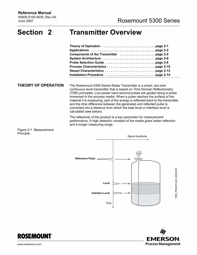
THEORY OF OPERATION The Rosemount 5300 Series Radar Transmitter is a smart, two-wire continuous level transmitter that is based on Time Domain Reflectometry (TDR) principles. Low power nano-second-pulses are guided along a probe immersed in the process media. When a pulse reaches the surface of the material it is measuring, part of the energy is reflected back to the transmitter, and the time difference between the generated and reflected pulse is converted into a distance from which the total level or interface level is calculated (see below).
The reflectivity of the product is a key parameter for measurement performance. A high dielectric constant of the media gives better reflection and a longer measuring range.
Figure 2-1. Measurement Principle.
Time
TDR
_PR
INC
IPLE
S_5
300.
EPS
Reference Pulse
Level
Interface Level
Signal Amplitude
www.rosemount.com
Reference Manual00809-0100-4530, Rev AA
June 2007Rosemount 5300 Series
APPLICATIONS The Rosemount 5300 Series Radar Transmitter program is suited for aggregate (total) level measurements on most liquids, semi-liquids, solids, and liquid/liquid interfaces.
Guided microwave technology offers highest reliability and precision which ensure measurements are virtually unaffected by temperature, pressure, vapor gas mixtures, density, turbulence, bubbling/boiling, low level, varying dielectric media, pH, and viscosity.
Guided wave radar technology in combination with advanced signal processing makes the 5300 transmitters suitable for a wide range of applications:
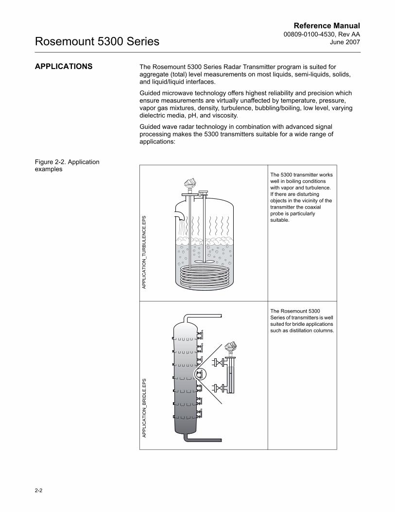
Figure 2-2. Application examples
The 5300 transmitter works well in boiling conditions with vapor and turbulence. If there are disturbing objects in the vicinity of the transmitter the coaxial probe is particularly suitable.
The Rosemount 5300 Series of transmitters is well suited for bridle applications such as distillation columns.
APP
LIC
ATI
ON
_TU
RB
ULE
NC
E.E
PSA
PPLI
CA
TIO
N_B
RID
LE.E
PS
2-2
Reference Manual 00809-0100-4530, Rev AAJune 2007 Rosemount 5300 Series
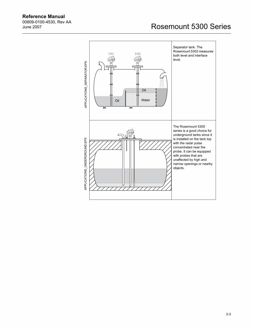
Separator tank. The Rosemount 5302 measures both level and interface level.
The Rosemount 5300 series is a good choice for underground tanks since it is installed on the tank top with the radar pulse concentrated near the probe. It can be equipped with probes that are unaffected by high and narrow openings or nearby objects.
Oil
Oil Water
APP
LIC
ATI
ON
S_U
ND
ER
GR
OU
ND
.EPS
APP
LIC
ATI
ON
S_S
EPA
RA
TOR
.EPS
2-3
Reference Manual00809-0100-4530, Rev AA
June 2007Rosemount 5300 Series
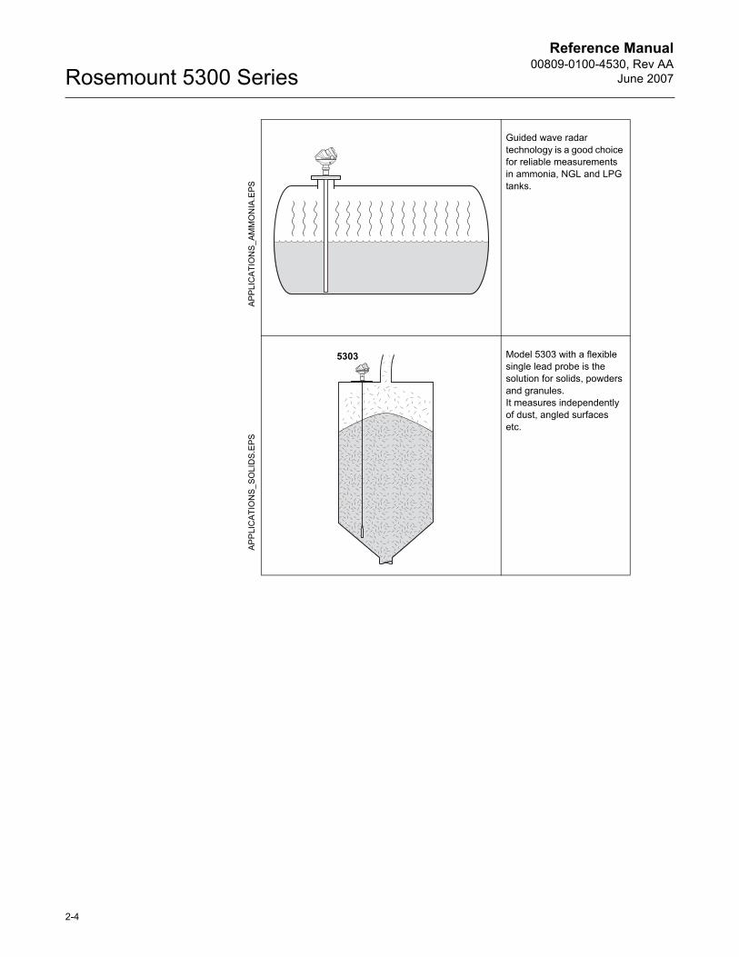
Guided wave radar technology is a good choice for reliable measurements in ammonia, NGL and LPG tanks.
Model 5303 with a flexible single lead probe is the solution for solids, powders and granules. It measures independently of dust, angled surfaces etc.
5303
APP
LIC
ATI
ON
S_A
MM
ON
IA.E
PSA
PP
LIC
ATIO
NS_
SO
LID
S.E
PS
2-4
Reference Manual 00809-0100-4530, Rev AAJune 2007 Rosemount 5300 Series
COMPONENTS OF THE TRANSMITTER
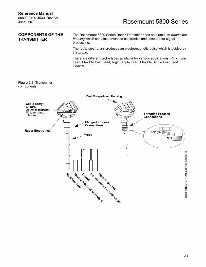
The Rosemount 5300 Series Radar Transmitter has an aluminum transmitter housing which contains advanced electronics and software for signal processing.
The radar electronics produces an electromagnetic pulse which is guided by the probe.
There are different probe types available for various applications: Rigid Twin Lead, Flexible Twin Lead, Rigid Single Lead, Flexible Single Lead, and Coaxial.
Figure 2-3. Transmitter components.
Radar ElectronicsProbe
Dual Compartment Housing
Cable Entry:½" NPT.Optional adapters:M20, eurofast,minifast Threaded Process
Connections
Flanged Process Connections
BSP (G)
NPT
Coaxial
Flexible Twin Lead with weight
Rigid Twin LeadC
OM
PON
EN
TS_T
RAN
SM
ITTE
R_5
300.
EPS
Rigid Single Lead
Flexible Single Lead with weight
2-5
Reference Manual00809-0100-4530, Rev AA
June 2007Rosemount 5300 Series
SYSTEM ARCHITECTURE
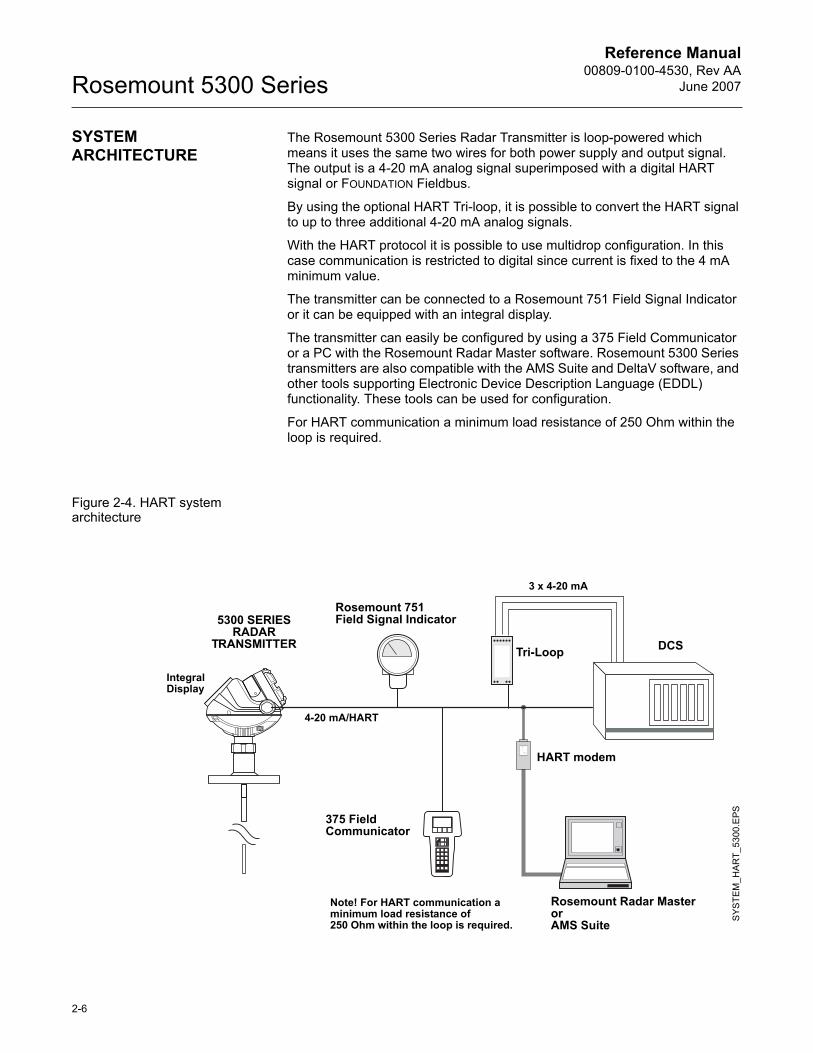
The Rosemount 5300 Series Radar Transmitter is loop-powered which means it uses the same two wires for both power supply and output signal. The output is a 4-20 mA analog signal superimposed with a digital HART signal or FOUNDATION Fieldbus.
By using the optional HART Tri-loop, it is possible to convert the HART signal to up to three additional 4-20 mA analog signals.
With the HART protocol it is possible to use multidrop configuration. In this case communication is restricted to digital since current is fixed to the 4 mA minimum value.
The transmitter can be connected to a Rosemount 751 Field Signal Indicator or it can be equipped with an integral display.
The transmitter can easily be configured by using a 375 Field Communicator or a PC with the Rosemount Radar Master software. Rosemount 5300 Series transmitters are also compatible with the AMS Suite and DeltaV software, and other tools supporting Electronic Device Description Language (EDDL) functionality. These tools can be used for configuration.
For HART communication a minimum load resistance of 250 Ohm within the loop is required.
Figure 2-4. HART system architecture
4-20 mA/HART
Rosemount 751 Field Signal Indicator
375 Field Communicator
HART modem
5300 SERIES RADAR
TRANSMITTER DCSTri-Loop
3 x 4-20 mA
Rosemount Radar MasterorAMS Suite
Integral Display
SYS
TEM
_HA
RT_
5300
.EPS
Note! For HART communication a minimum load resistance of 250 Ohm within the loop is required.
2-6
Reference Manual 00809-0100-4530, Rev AAJune 2007 Rosemount 5300 Series
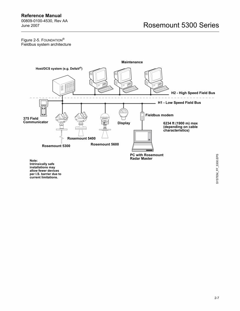
Figure 2-5. FOUNDATION® Fieldbus system architecture
Host/DCS system (e.g. DeltaV®)
SY
STE
M_F
F_53
00.E
PS
375 Field Communicator
Maintenance
Rosemount 5300
Rosemount 5400Rosemount 5600
PC with Rosemount Radar Master
Fieldbus modem
H2 - High Speed Field Bus
H1 - Low Speed Field Bus
6234 ft (1900 m) max(depending on cable characteristics)
Display
Note:Intrinsically safeinstallations mayallow fewer devicesper I.S. barrier due tocurrent limitations.
2-7
Reference Manual00809-0100-4530, Rev AA
June 2007Rosemount 5300 Series
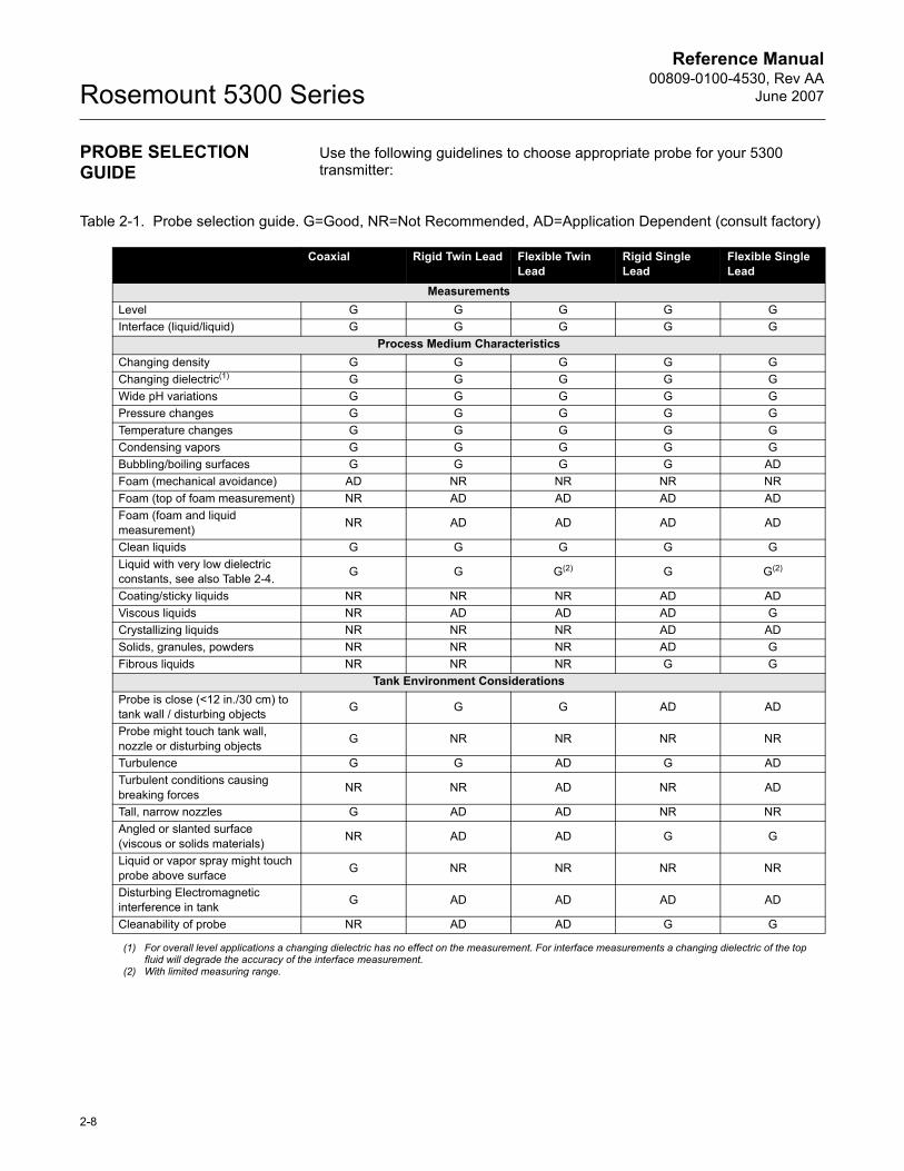
PROBE SELECTION GUIDE
Use the following guidelines to choose appropriate probe for your 5300 transmitter:
Table 2-1. Probe selection guide. G=Good, NR=Not Recommended, AD=Application Dependent (consult factory)
Coaxial Rigid Twin Lead Flexible Twin Lead
Rigid Single Lead
Flexible Single Lead
MeasurementsLevel G G G G GInterface (liquid/liquid) G G G G G
Process Medium CharacteristicsChanging density G G G G GChanging dielectric(1) G G G G GWide pH variations G G G G GPressure changes G G G G GTemperature changes G G G G GCondensing vapors G G G G GBubbling/boiling surfaces G G G G ADFoam (mechanical avoidance) AD NR NR NR NRFoam (top of foam measurement) NR AD AD AD ADFoam (foam and liquid measurement) NR AD AD AD AD
Clean liquids G G G G GLiquid with very low dielectric constants, see also Table 2-4. G G G(2) G G(2)
Coating/sticky liquids NR NR NR AD ADViscous liquids NR AD AD AD GCrystallizing liquids NR NR NR AD ADSolids, granules, powders NR NR NR AD GFibrous liquids NR NR NR G G
Tank Environment ConsiderationsProbe is close (<12 in./30 cm) to tank wall / disturbing objects G G G AD AD
Probe might touch tank wall, nozzle or disturbing objects G NR NR NR NR
Turbulence G G AD G ADTurbulent conditions causing breaking forces NR NR AD NR AD
Tall, narrow nozzles G AD AD NR NRAngled or slanted surface (viscous or solids materials) NR AD AD G G
Liquid or vapor spray might touch probe above surface G NR NR NR NR
Disturbing Electromagnetic interference in tank G AD AD AD AD
Cleanability of probe NR AD AD G G
(1) For overall level applications a changing dielectric has no effect on the measurement. For interface measurements a changing dielectric of the top fluid will degrade the accuracy of the interface measurement.
(2) With limited measuring range.
2-8
Reference Manual 00809-0100-4530, Rev AAJune 2007 Rosemount 5300 Series
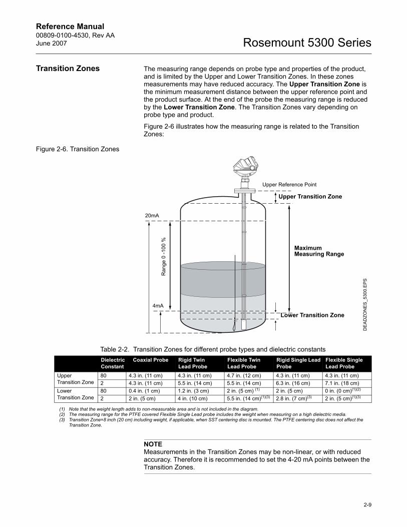
Transition Zones The measuring range depends on probe type and properties of the product, and is limited by the Upper and Lower Transition Zones. In these zones measurements may have reduced accuracy. The Upper Transition Zone is the minimum measurement distance between the upper reference point and the product surface. At the end of the probe the measuring range is reduced by the Lower Transition Zone. The Transition Zones vary depending on probe type and product.
Figure 2-6 illustrates how the measuring range is related to the Transition Zones:
Figure 2-6. Transition Zones
NOTEMeasurements in the Transition Zones may be non-linear, or with reduced accuracy. Therefore it is recommended to set the 4-20 mA points between the Transition Zones.
4mA
20mA
Upper Transition Zone
Lower Transition Zone
Ran
ge 0
-100
%
Maximum Measuring Range
Upper Reference Point
DE
AD
ZON
ES_5
300.
EPS
Table 2-2. Transition Zones for different probe types and dielectric constantsDielectric Constant
Coaxial Probe Rigid Twin Lead Probe
Flexible Twin Lead Probe
Rigid Single Lead Probe
Flexible Single Lead Probe
Upper Transition Zone
80 4.3 in. (11 cm) 4.3 in. (11 cm) 4.7 in. (12 cm) 4.3 in. (11 cm) 4.3 in. (11 cm)2 4.3 in. (11 cm) 5.5 in. (14 cm) 5.5 in. (14 cm) 6.3 in. (16 cm) 7.1 in. (18 cm)
Lower Transition Zone
80 0.4 in. (1 cm) 1.2 in. (3 cm) 2 in. (5 cm) (1) 2 in. (5 cm) 0 in. (0 cm)(1)(2)
2 2 in. (5 cm) 4 in. (10 cm) 5.5 in. (14 cm)(1)(3) 2.8 in. (7 cm)(3) 2 in. (5 cm)(1)(3)
(1) Note that the weight length adds to non-measurable area and is not included in the diagram.(2) The measuring range for the PTFE covered Flexible Single Lead probe includes the weight when measuring on a high dielectric media.(3) Transition Zone=8 inch (20 cm) including weight, if applicable, when SST centering disc is mounted. The PTFE centering disc does not affect the
Transition Zone.
2-9
Reference Manual00809-0100-4530, Rev AA
June 2007Rosemount 5300 Series
PROCESS CHARACTERISTICS
The Rosemount 5300 Series has a high sensitivity due to its advanced signal processing and high signal to noise ratio, which makes it able to handle various disturbances. However, the following circumstances should be considered before mounting the transmitter.
Coating Coating on the probe should be avoided since the sensitivity of the transmitter may be decreased leading to measurement errors. In viscous or sticky applications, periodic cleaning may be required.
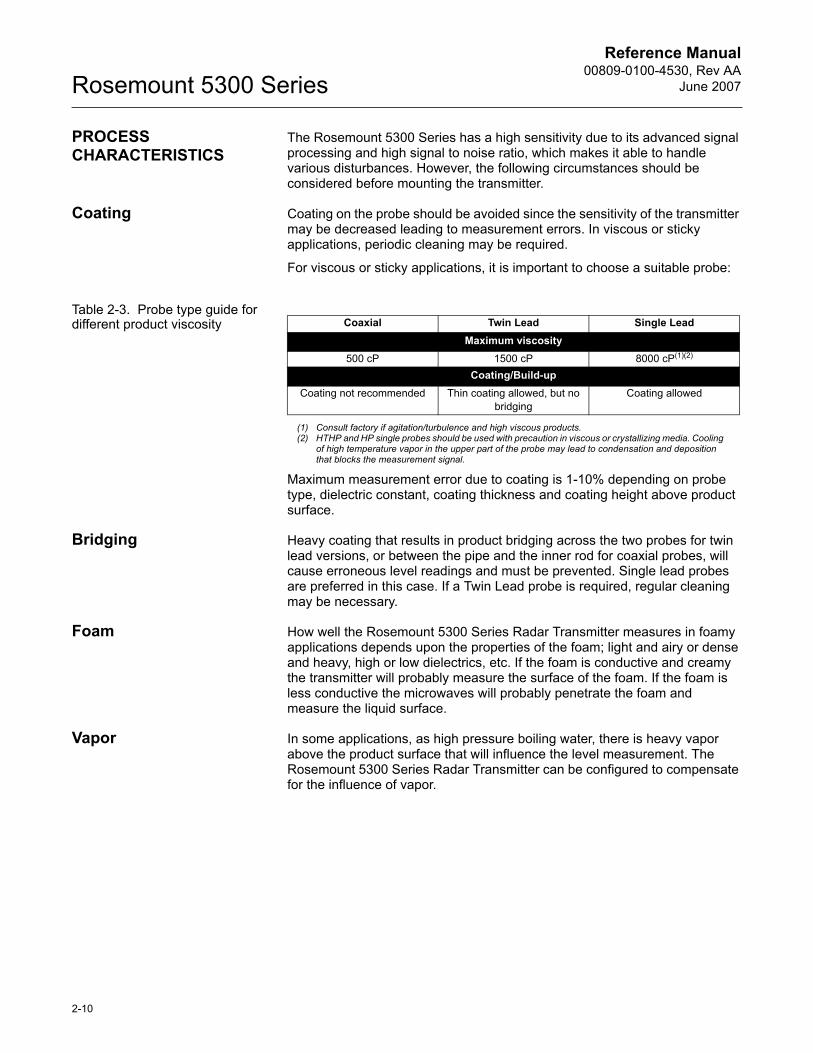
For viscous or sticky applications, it is important to choose a suitable probe:
Table 2-3. Probe type guide for different product viscosity
Maximum measurement error due to coating is 1-10% depending on probe type, dielectric constant, coating thickness and coating height above product surface.
Bridging Heavy coating that results in product bridging across the two probes for twin lead versions, or between the pipe and the inner rod for coaxial probes, will cause erroneous level readings and must be prevented. Single lead probes are preferred in this case. If a Twin Lead probe is required, regular cleaning may be necessary.
Foam How well the Rosemount 5300 Series Radar Transmitter measures in foamy applications depends upon the properties of the foam; light and airy or dense and heavy, high or low dielectrics, etc. If the foam is conductive and creamy the transmitter will probably measure the surface of the foam. If the foam is less conductive the microwaves will probably penetrate the foam and measure the liquid surface.
Vapor In some applications, as high pressure boiling water, there is heavy vapor above the product surface that will influence the level measurement. The Rosemount 5300 Series Radar Transmitter can be configured to compensate for the influence of vapor.
Coaxial Twin Lead Single LeadMaximum viscosity
500 cP 1500 cP 8000 cP(1)(2)
(1) Consult factory if agitation/turbulence and high viscous products.(2) HTHP and HP single probes should be used with precaution in viscous or crystallizing media. Cooling
of high temperature vapor in the upper part of the probe may lead to condensation and deposition that blocks the measurement signal.
Coating/Build-upCoating not recommended Thin coating allowed, but no
bridgingCoating allowed
2-10
Reference Manual 00809-0100-4530, Rev AAJune 2007 Rosemount 5300 Series
Measuring Range The measuring range differs depending on probe type and characteristics of the application. The values given in Table 2-4 can be used as a guideline for clean liquids.
Table 2-4. Measuring Range
The maximum measuring range differs depending on application according to:
� Disturbing objects close to the probe.� Media with higher dielectric constant (εr) gives better reflection and
allows a longer measuring range.� Surface foam and particles in the tank atmosphere are also
circumstances that might affect measuring performance.� Coating/contamination can reduce the measuring range. � Disturbing EMC environment in tank.� Tank material (e.g. concrete or plastic) for measurements with single
lead probes.
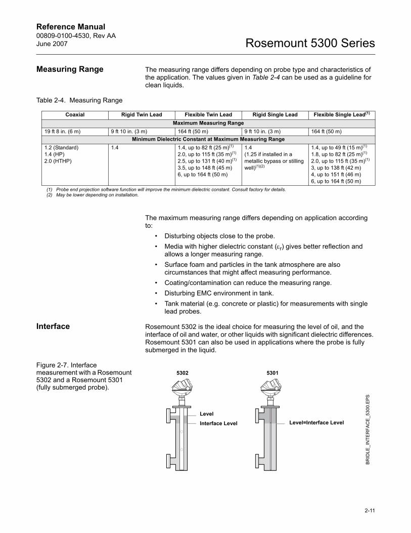
Interface Rosemount 5302 is the ideal choice for measuring the level of oil, and the interface of oil and water, or other liquids with significant dielectric differences. Rosemount 5301 can also be used in applications where the probe is fully submerged in the liquid.
Figure 2-7. Interface measurement with a Rosemount 5302 and a Rosemount 5301 (fully submerged probe).
Coaxial Rigid Twin Lead Flexible Twin Lead Rigid Single Lead Flexible Single Lead(1)
Maximum Measuring Range19 ft 8 in. (6 m) 9 ft 10 in. (3 m) 164 ft (50 m) 9 ft 10 in. (3 m) 164 ft (50 m)
Minimum Dielectric Constant at Maximum Measuring Range1.2 (Standard)1.4 (HP)2.0 (HTHP)
1.4 1.4, up to 82 ft (25 m)(1)
2.0, up to 115 ft (35 m)(1)
2.5, up to 131 ft (40 m)(1)
3.5, up to 148 ft (45 m)6, up to 164 ft (50 m)
1.4(1.25 if installed in a metallic bypass or stilling well)(1)(2)
1.4, up to 49 ft (15 m)(1)
1.8, up to 82 ft (25 m)(1)
2.0, up to 115 ft (35 m)(1)
3, up to 138 ft (42 m)4, up to 151 ft (46 m)6, up to 164 ft (50 m)
(1) Probe end projection software function will improve the minimum dielectric constant. Consult factory for details.(2) May be lower depending on installation.
BR
IDLE
_IN
TER
FAC
E_53
00.E
PS
Level
5302 5301
Interface Level Level=Interface Level
2-11
Reference Manual00809-0100-4530, Rev AA
June 2007Rosemount 5300 Series
For measuring the interface level, the transmitter uses the residual wave of the first reflection. Part of the wave, which was not reflected at the upper product surface, continues until it is reflected at the lower product surface. The speed of this wave depends fully on the dielectric constant of the upper product.
If interface is to be measured, the following criteria have to be fulfilled:� The dielectric constant of the upper product must be known and should
not vary. The Rosemount Radar Master software has a built-in dielectric constant calculator to assist the user in determining the dielectric constant of the upper product. (see �Dielectric Constant/Dielectric Range� on page 5-22).
� The dielectric constant of the upper product must have a lower dielectric constant than the lower product in order to have a distinct reflection.
� The difference between the dielectric constants for the two products must be larger than 6.
� Maximum dielectric constant for the upper product is 10 for the coaxial probe, 7 for the twin lead and 8 for the single lead probes.
� The upper product thickness must be larger than 5.1 in. (0.13 m) for all probes except the HTHP coaxial probe, which requires 8 in. (0.2 m), in order to distinguish the echoes of the two liquids.
The maximum allowable upper product thickness/measuring range is primarily determined by the dielectric constants of the two liquids.
Target applications include interfaces between oil / oil-like and water / water-like liquids with low (<3) upper product dielectric constant and high (>20) lower product dielectric constant.
For such applications, maximum measuring range is only limited by the length of the coaxial, rigid twin and rigid single lead probes.
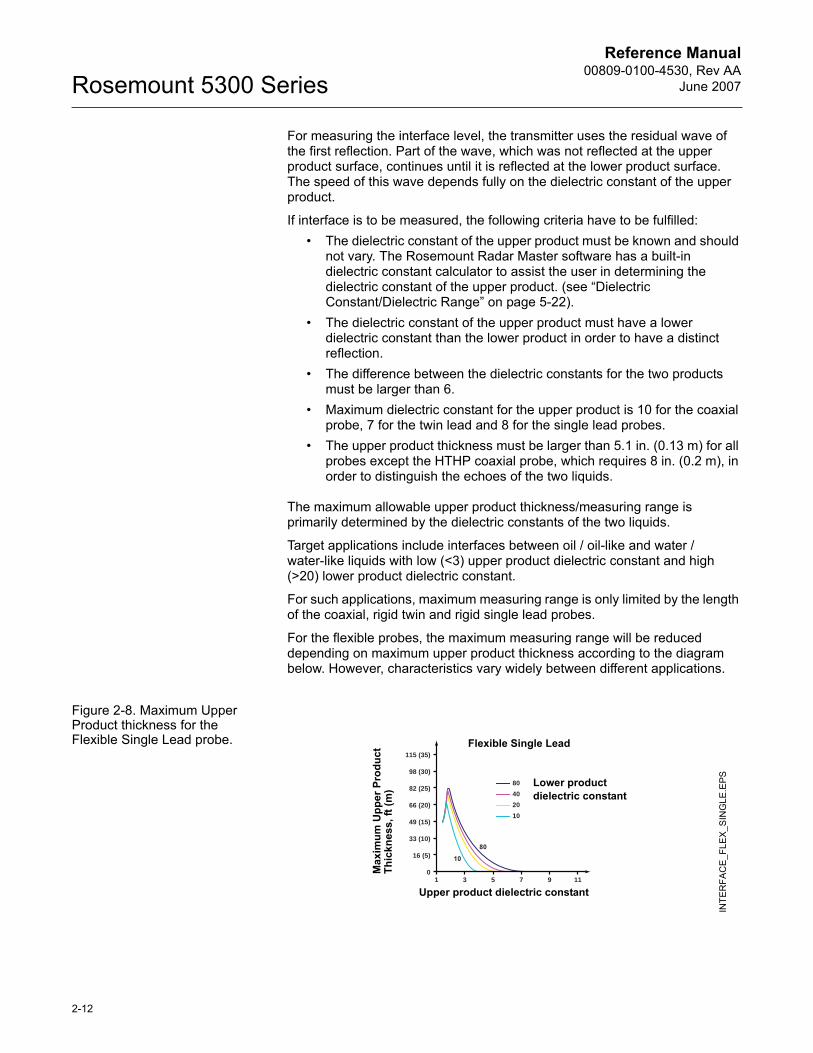
For the flexible probes, the maximum measuring range will be reduced depending on maximum upper product thickness according to the diagram below. However, characteristics vary widely between different applications.
Figure 2-8. Maximum Upper Product thickness for the Flexible Single Lead probe.
1 3 5 7 9 110
16 (5)
33 (10)
49 (15)
66 (20)
82 (25)
98 (30)
115 (35)
80402010
INTE
RFA
CE
_FLE
X_S
ING
LE.E
PS
Upper product dielectric constant
Max
imum
Upp
er P
rodu
ct
Thic
knes
s, ft
(m) Lower product
dielectric constant
Flexible Single Lead
2-12
Reference Manual 00809-0100-4530, Rev AAJune 2007 Rosemount 5300 Series
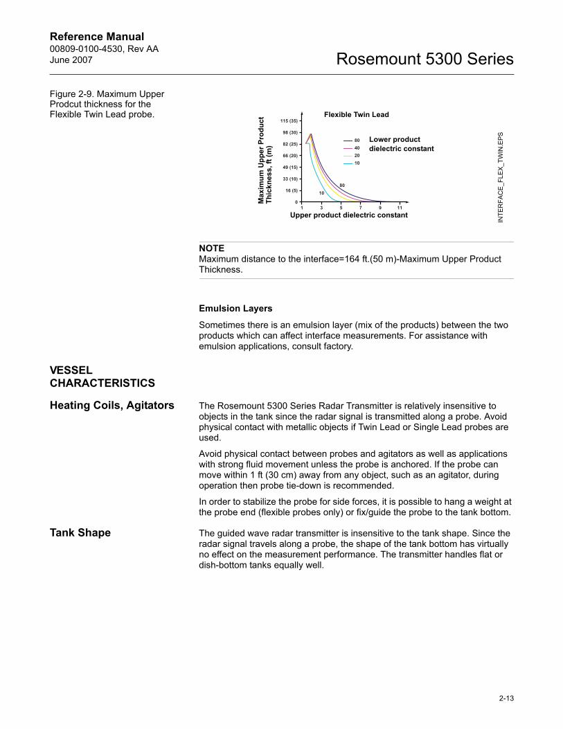
Figure 2-9. Maximum Upper Prodcut thickness for the Flexible Twin Lead probe.
NOTEMaximum distance to the interface=164 ft.(50 m)-Maximum Upper Product Thickness.
Emulsion Layers
Sometimes there is an emulsion layer (mix of the products) between the two products which can affect interface measurements. For assistance with emulsion applications, consult factory.
VESSEL CHARACTERISTICS
Heating Coils, Agitators The Rosemount 5300 Series Radar Transmitter is relatively insensitive to objects in the tank since the radar signal is transmitted along a probe. Avoid physical contact with metallic objects if Twin Lead or Single Lead probes are used.
Avoid physical contact between probes and agitators as well as applications with strong fluid movement unless the probe is anchored. If the probe can move within 1 ft (30 cm) away from any object, such as an agitator, during operation then probe tie-down is recommended.
In order to stabilize the probe for side forces, it is possible to hang a weight at the probe end (flexible probes only) or fix/guide the probe to the tank bottom.
Tank Shape The guided wave radar transmitter is insensitive to the tank shape. Since the radar signal travels along a probe, the shape of the tank bottom has virtually no effect on the measurement performance. The transmitter handles flat or dish-bottom tanks equally well.
INTE
RFA
CE
_FLE
X_T
WIN
.EPSLower product
dielectric constant
Upper product dielectric constant
Flexible Twin Lead
Max
imum
Upp
er P
rodu
ct
Thic
knes
s, ft
(m)
2-13
Reference Manual00809-0100-4530, Rev AA
June 2007Rosemount 5300 Series
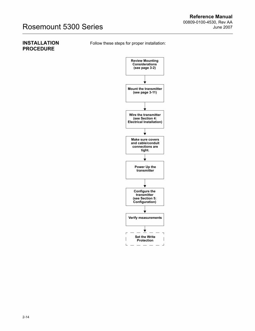
INSTALLATION PROCEDURE
Follow these steps for proper installation:
Review Mounting Considerations(see page 3-2)
Mount the transmitter(see page 3-11)
Wire the transmitter(see Section 4:
Electrical Installation)
Make sure covers and cable/conduit connections are
tight.
Power Up the transmitter
Configure the transmitter
(see Section 5: Configuration)
Verify measurements
Set the Write Protection
2-14
Reference Manual 00809-0100-4530, Rev AAJune 2007 Rosemount 5300 Series
Section 3 Mechanical Installation
Safety messages . . . . . . . . . . . . . . . . . . . . . . . . . . . . . . . . . page 3-1Mounting Considerations . . . . . . . . . . . . . . . . . . . . . . . . . page 3-2Mounting . . . . . . . . . . . . . . . . . . . . . . . . . . . . . . . . . . . . . . . page 3-11
SAFETY MESSAGES Procedures and instructions in this section may require special precautions to ensure the safety of the personnel performing the operations. Information that raises potential safety issues is indicated by a warning symbol ( ). Please refer to the following safety messages before performing an operation preceded by this symbol.
Failure to follow safe installation and servicing guidelines could result in death or serious injury:Make sure only qualified personnel perform the installation.
Use the equipment only as specified in this manual. Failure to do so may impair the protection provided by the equipment.
Do not perform any service other than those contained in this manual unless you are qualified.
Process leaks could result in death or serious injury.Make sure that the transmitter is handled carefully. If the Process Seal is damaged, gas might escape from the tank if the transmitter head is removed from the probe.
High voltage that may be present on leads could cause electrical shock:Probes covered with plastic and/or with plastic discs may generate an ignition-capable level of electrostatic charge under certain extreme conditions. Therefore, when the probe is used in a potentially explosive atmosphere, appropriate measures must be taken to prevent electrostatic discharge.
www.rosemount.com
Reference Manual00809-0100-4530, Rev AA
June 2007Rosemount 5300 Series
MOUNTING CONSIDERATIONS
Before you install the Rosemount 5300 Series Radar Transmitter, be sure to consider specific mounting requirements, vessel characteristics and process characteristics.
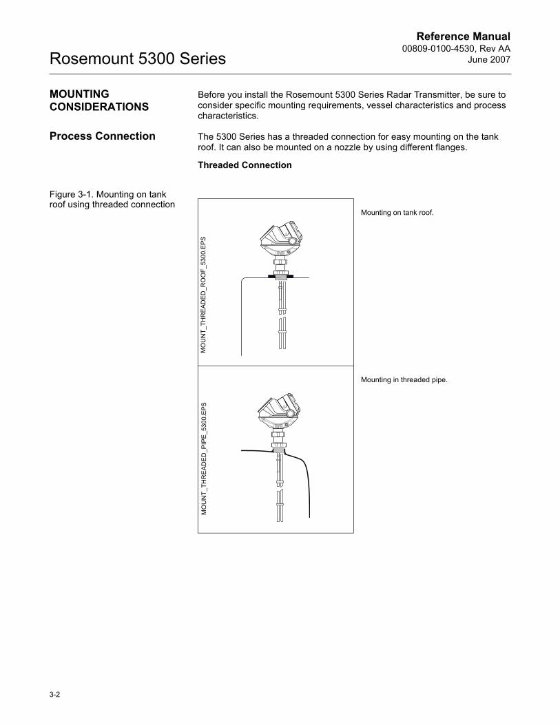
Process Connection The 5300 Series has a threaded connection for easy mounting on the tank roof. It can also be mounted on a nozzle by using different flanges.
Threaded Connection
Figure 3-1. Mounting on tank roof using threaded connection
Mounting on tank roof.
Mounting in threaded pipe.
MO
UN
T_TH
RE
ADE
D_R
OO
F_53
00.E
PSM
OU
NT_
THR
EA
DE
D_P
IPE
_530
0.E
PS
3-2
Reference Manual 00809-0100-4530, Rev AAJune 2007 Rosemount 5300 Series
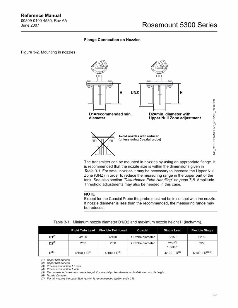
Flange Connection on Nozzles
Figure 3-2. Mounting in nozzles
The transmitter can be mounted in nozzles by using an appropriate flange. It is recommended that the nozzle size is within the dimensions given in Table 3-1. For small nozzles it may be necessary to increase the Upper Null Zone (UNZ) in order to reduce the measuring range in the upper part of the tank. See also section �Disturbance Echo Handling� on page 7-8. Amplitude Threshold adjustments may also be needed in this case.
NOTEExcept for the Coaxial Probe the probe must not be in contact with the nozzle. If nozzle diameter is less than the recommended, the measuring range may be reduced.
H
D2=min. diameter with Upper Null Zone adjustment
HUNZ
NO
_RED
UC
ER/M
OU
NT_
NO
ZZLE
_530
0.E
PS
Avoid nozzles with reducer(unless using Coaxial probe)
D1=recommended min. diameter
Table 3-1. Minimum nozzle diameter D1/D2 and maximum nozzle height H (inch/mm).
Rigid Twin Lead Flexible Twin Lead Coaxial Single Lead Flexible Single
D1(1) 4/100 4/100 > Probe diameter 6/150 6/150
D2(2) 2/50 2/50 > Probe diameter 2/50(3)
1.5/38(4)2/50
H(5) 4/100 + D(6) 4/100 + D(6) - 4/100 + D(6) 4/100 + D(6) (7)
(1) Upper Null Zone=0.(2) Upper Null Zone>0. (3) Process connection 1.5 inch.(4) Process connection 1 inch.(5) Recommended maximum nozzle height. For coaxial probes there is no limitation on nozzle height.(6) Nozzle diameter. (7) For tall nozzles the Long Stud version is recommended (option code LS).
3-3
Reference Manual00809-0100-4530, Rev AA
June 2007Rosemount 5300 Series
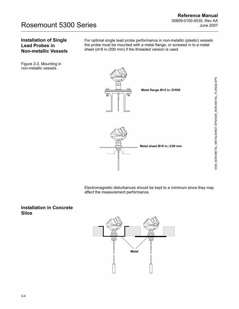
Installation of Single Lead Probes in Non-metallic Vessels
For optimal single lead probe performance in non-metallic (plastic) vessels the probe must be mounted with a metal flange, or screwed in to a metal sheet (d>8 in./200 mm) if the threaded version is used.
Figure 3-3. Mounting in non-metallic vessels.
Electromagnetic disturbances should be kept to a minimum since they may affect the measurement performance.
Installation in Concrete Silos
Metal flange Ø>2 in./DN50
Metal sheet Ø>8 in./200 mm
5300
_NO
N-M
ETA
L_M
ETAL
SH
EET
.EPS
/530
0_N
ON
-ME
TAL_
FLAN
GE
.EPS
Metal
3-4
Reference Manual 00809-0100-4530, Rev AAJune 2007 Rosemount 5300 Series
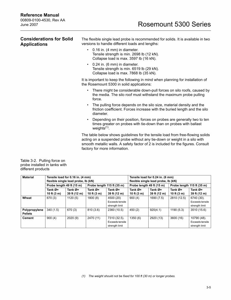
Considerations for Solid Applications
The flexible single lead probe is recommended for solids. It is available in two versions to handle different loads and lengths:
� 0.16 in. (4 mm) in diameter. Tensile strength is min. 2698 lb (12 kN). Collapse load is max. 3597 lb (16 kN).
� 0.24 in. (6 mm) in diameter.Tensile strength is min. 6519 lb (29 kN).Collapse load is max. 7868 lb (35 kN).
It is important to keep the following in mind when planning for installation of the Rosemount 5300 in solid applications:
� There might be considerable down-pull forces on silo roofs, caused by the media. The silo roof must withstand the maximum probe pulling force.
� The pulling force depends on the silo size, material density and the friction coefficient. Forces increase with the buried length and the silo diameter.
� Depending on their position, forces on probes are generally two to ten times greater on probes with tie-down than on probes with ballast weights(1).
The table below shows guidelines for the tensile load from free-flowing solids acting on a suspended probe without any tie-down or weight in a silo with smooth metallic walls. A safety factor of 2 is included for the figures. Consult factory for more information.
Table 3-2. Pulling force on probe installed in tanks with different products
(1) The weight should not be fixed for 100 ft (30 m) or longer probes.
Material Tensile load for 0.16 in. (4 mm) flexible single lead probe, lb (kN)
Tensile load for 0.24 in. (6 mm) flexible single lead probe, lb (kN)
Probe length 49 ft (15 m) Probe length 115 ft (35 m) Probe length 49 ft (15 m) Probe length 115 ft (35 m)Tank Ø= 10 ft (3 m)
Tank Ø= 39 ft (12 m)
Tank Ø= 10 ft (3 m)
Tank Ø= 39 ft (12 m)
Tank Ø= 10 ft (3 m)
Tank Ø= 39 ft (12 m)
Tank Ø= 10 ft (3 m)
Tank Ø= 39 ft (12 m)
Wheat 670 (3) 1120 (5) 1800 (8) 4500 (20)Exceeds tensile strength limit
900 (4) 1690 (7.5) 2810 (12.5) 6740 (30). Exceeds tensile strength limit
PolypropylenePellets
340 (1.5) 670 (3) 810 (3.6) 2360 (10.5) 450 (2) 920(4.1) 1190 (5.3) 3510 (15.6)
Cement 900 (4) 2020 (9) 2470 (11) 7310 (32.5). Exceeds tensile strength limit
1350 (6) 2920 (13) 3600 (16) 10790 (48). Exceeds tensile strength limit
3-5
Reference Manual00809-0100-4530, Rev AA
June 2007Rosemount 5300 Series
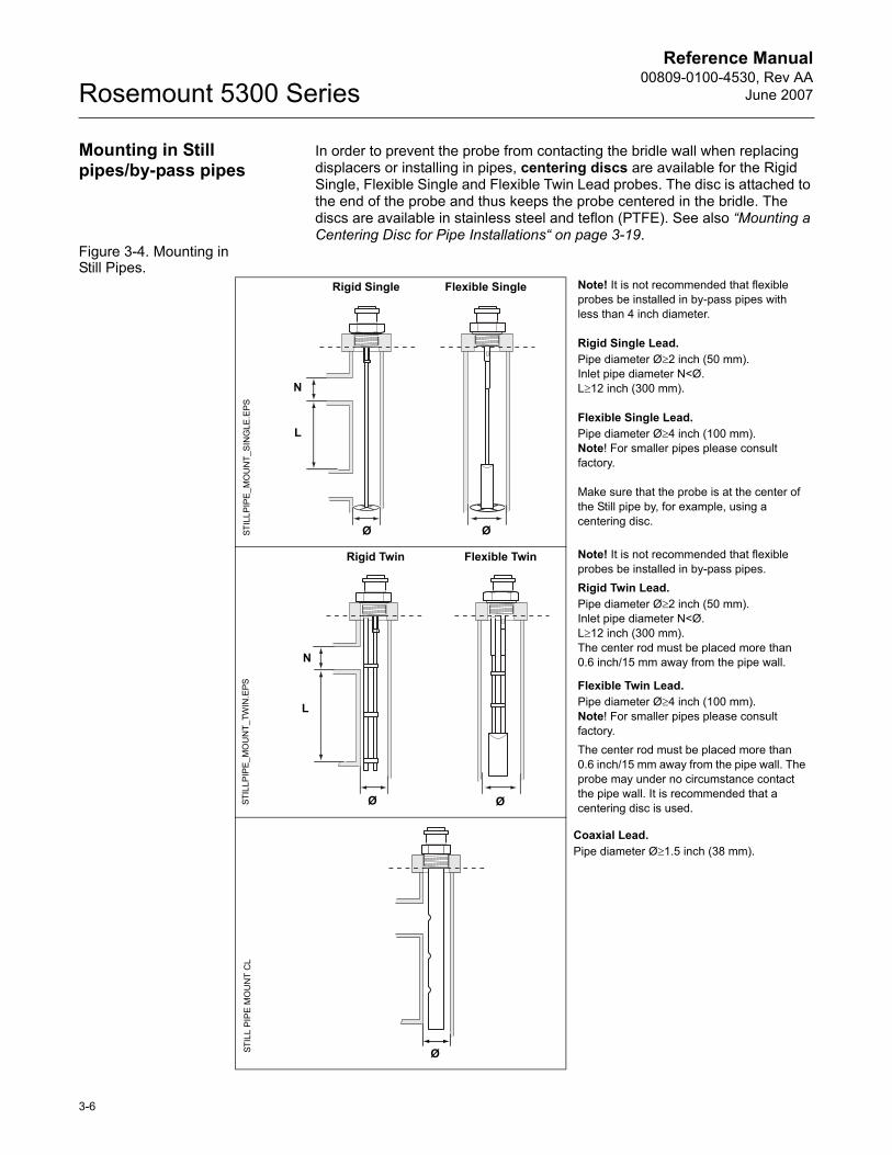
Mounting in Still pipes/by-pass pipes
In order to prevent the probe from contacting the bridle wall when replacing displacers or installing in pipes, centering discs are available for the Rigid Single, Flexible Single and Flexible Twin Lead probes. The disc is attached to the end of the probe and thus keeps the probe centered in the bridle. The discs are available in stainless steel and teflon (PTFE). See also �Mounting a Centering Disc for Pipe Installations� on page 3-19.
Figure 3-4. Mounting in Still Pipes.
Note! It is not recommended that flexible probes be installed in by-pass pipes with less than 4 inch diameter.
Rigid Single Lead.Pipe diameter Ø≥2 inch (50 mm).Inlet pipe diameter N<Ø.L≥12 inch (300 mm).
Flexible Single Lead.Pipe diameter Ø≥4 inch (100 mm).Note! For smaller pipes please consult factory.
Make sure that the probe is at the center of the Still pipe by, for example, using a centering disc.
Note! It is not recommended that flexible probes be installed in by-pass pipes.Rigid Twin Lead.Pipe diameter Ø≥2 inch (50 mm).Inlet pipe diameter N<Ø.L≥12 inch (300 mm).The center rod must be placed more than 0.6 inch/15 mm away from the pipe wall.
Flexible Twin Lead.Pipe diameter Ø≥4 inch (100 mm).Note! For smaller pipes please consult factory.The center rod must be placed more than 0.6 inch/15 mm away from the pipe wall. The probe may under no circumstance contact the pipe wall. It is recommended that a centering disc is used.
Coaxial Lead.Pipe diameter Ø≥1.5 inch (38 mm).
STIL
LPIP
E_M
OU
NT_
SIN
GLE
.EPS
Ø
L
N
Rigid Single
Ø
Flexible Single
ØSTIL
LPIP
E_M
OU
NT_
TWIN
.EPS
Flexible Twin
Ø
Rigid Twin
N
L
STIL
L P
IPE
MO
UN
T C
L
Ø
3-6
Reference Manual 00809-0100-4530, Rev AAJune 2007 Rosemount 5300 Series
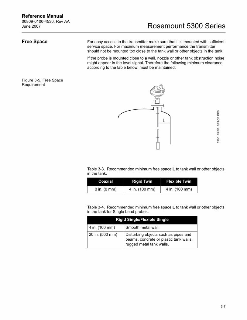
Free Space For easy access to the transmitter make sure that it is mounted with sufficient service space. For maximum measurement performance the transmitter should not be mounted too close to the tank wall or other objects in the tank.
If the probe is mounted close to a wall, nozzle or other tank obstruction noise might appear in the level signal. Therefore the following minimum clearance, according to the table below, must be maintained:
Figure 3-5. Free Space Requirement
Table 3-3. Recommended minimum free space L to tank wall or other objects in the tank.
Coaxial Rigid Twin Flexible Twin
0 in. (0 mm) 4 in. (100 mm) 4 in. (100 mm)
Table 3-4. Recommended minimum free space L to tank wall or other objects in the tank for Single Lead probes.
Rigid Single/Flexible Single
4 in. (100 mm) Smooth metal wall.
20 in. (500 mm) Disturbing objects such as pipes and beams, concrete or plastic tank walls, rugged metal tank walls.
5300
_FR
EE_
SPA
CE.
EPS
3-7
Reference Manual00809-0100-4530, Rev AA
June 2007Rosemount 5300 Series
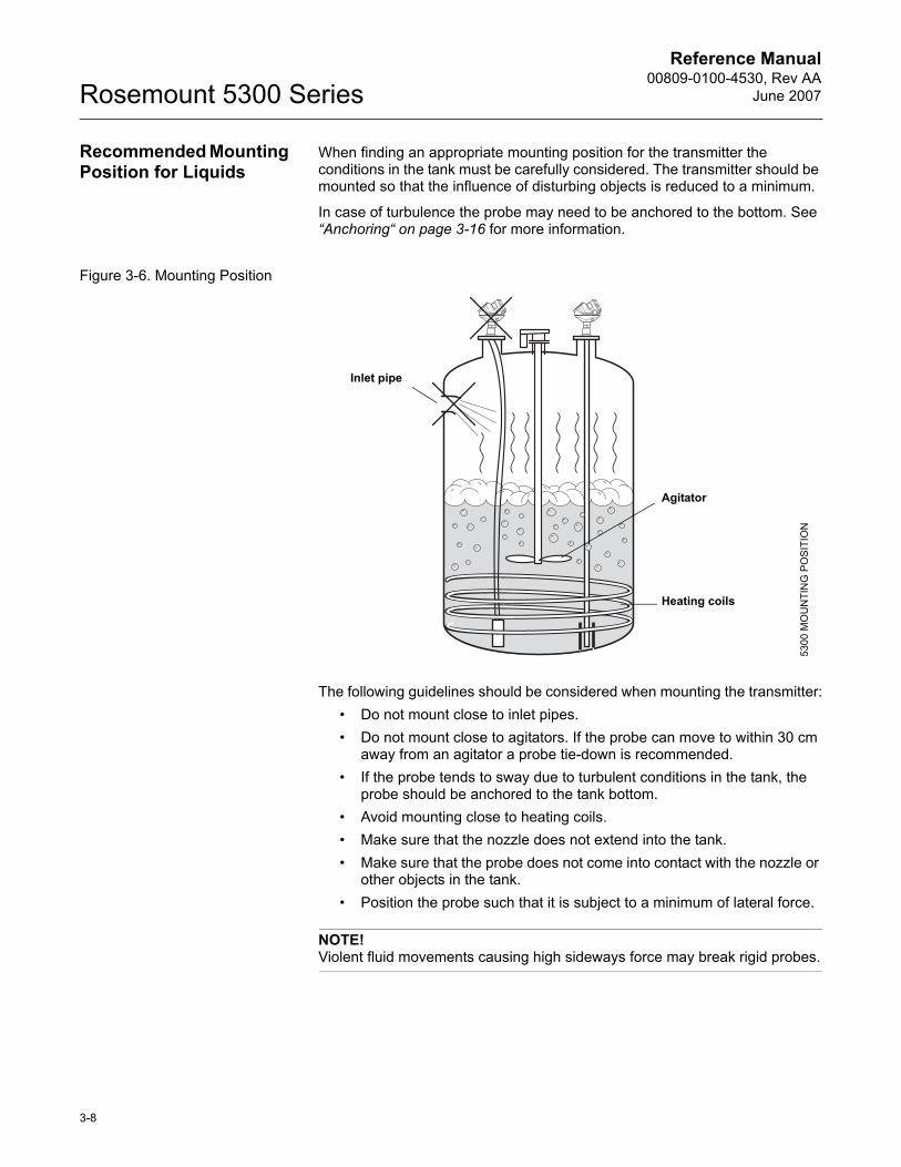
Recommended Mounting Position for Liquids
When finding an appropriate mounting position for the transmitter the conditions in the tank must be carefully considered. The transmitter should be mounted so that the influence of disturbing objects is reduced to a minimum.
In case of turbulence the probe may need to be anchored to the bottom. See �Anchoring� on page 3-16 for more information.
Figure 3-6. Mounting Position
The following guidelines should be considered when mounting the transmitter:� Do not mount close to inlet pipes.� Do not mount close to agitators. If the probe can move to within 30 cm
away from an agitator a probe tie-down is recommended.� If the probe tends to sway due to turbulent conditions in the tank, the
probe should be anchored to the tank bottom.� Avoid mounting close to heating coils.� Make sure that the nozzle does not extend into the tank.� Make sure that the probe does not come into contact with the nozzle or
other objects in the tank.� Position the probe such that it is subject to a minimum of lateral force.
NOTE!Violent fluid movements causing high sideways force may break rigid probes.
Inlet pipe
Heating coils
Agitator
5300
MO
UN
TIN
G P
OS
ITIO
N
3-8
Reference Manual 00809-0100-4530, Rev AAJune 2007 Rosemount 5300 Series
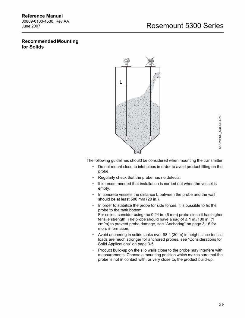
Recommended Mounting for Solids
The following guidelines should be considered when mounting the transmitter:� Do not mount close to inlet pipes in order to avoid product filling on the
probe.� Regularly check that the probe has no defects.� It is recommended that installation is carried out when the vessel is
empty.� In concrete vessels the distance L between the probe and the wall
should be at least 500 mm (20 in.).� In order to stabilize the probe for side forces, it is possible to fix the
probe to the tank bottom. For solids, consider using the 0.24 in. (6 mm) probe since it has higher tensile strength. The probe should have a sag of ≥ 1 in./100 in. (1 cm/m) to prevent probe damage, see �Anchoring� on page 3-16 for more information.
� Avoid anchoring in solids tanks over 98 ft (30 m) in height since tensile loads are much stronger for anchored probes, see �Considerations for Solid Applications� on page 3-5.
� Product build-up on the silo walls close to the probe may interfere with measurements. Choose a mounting position which makes sure that the probe is not in contact with, or very close to, the product build-up.
MO
UN
TIN
G_S
OLI
DS.
EPS
3-9
Reference Manual00809-0100-4530, Rev AA
June 2007Rosemount 5300 Series
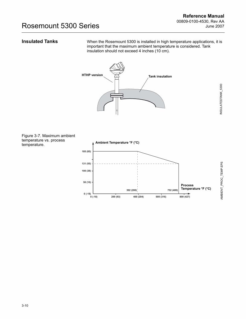
Insulated Tanks When the Rosemount 5300 is installed in high temperature applications, it is important that the maximum ambient temperature is considered. Tank insulation should not exceed 4 inches (10 cm).
Figure 3-7. Maximum ambient temperature vs. process temperature.
Tank insulation
INS
ULA
TED
TAN
K_5
300
HTHP version
AM
BIEN
T_P
RO
C_T
EM
P.EP
S
Process Temperature °F (°C)
Ambient Temperature °F (°C)
3-10
Reference Manual 00809-0100-4530, Rev AAJune 2007 Rosemount 5300 Series
MOUNTING Mount the transmitter with flange on a nozzle on top of the tank. The transmitter can also be mounted on a threaded connection. Make sure only qualified personnel perform the installation.
Flange Connection NOTEIf you need to remove the transmitter head from the probe, make sure that the Process Seal is carefully protected from dust and water. See �Removing the Transmitter Head� on page 7-28 for further information.
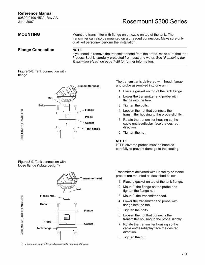
Figure 3-8. Tank connection with flange.
Figure 3-9. Tank connection with loose flange (�plate design�).
The transmitter is delivered with head, flange and probe assembled into one unit.
1. Place a gasket on top of the tank flange.2. Lower the transmitter and probe with
flange into the tank. 3. Tighten the bolts.4. Loosen the nut that connects the
transmitter housing to the probe slightly.5. Rotate the transmitter housing so the
cable entries/display face the desired direction.
6. Tighten the nut.
NOTE!PTFE covered probes must be handled carefully to prevent damage to the coating.
Transmitter head
Gasket
Flange
Tank flange
Nut
Probe
5300
_MO
UN
T_FL
AN
GE.
EPS
Bolts
Transmitters delivered with Hastelloy or Monel probes are mounted as described below:
1. Place a gasket on top of the tank flange.2. Mount(1) the flange on the probe and
tighten the flange nut. 3. Mount(1) the transmitter head.4. Lower the transmitter and probe with
flange into the tank. 5. Tighten the bolts.6. Loosen the nut that connects the
transmitter housing to the probe slightly.7. Rotate the transmitter housing so the
cable entries/display face the desired direction.
8. Tighten the nut.
(1) Flange and transmitter head are normally mounted at factory.
Transmitter head
Gasket
Flange
Tank flange
Probe
5300
_MO
UN
T_LO
OS
EFL
ANG
E.E
PS
Flange nut
Bolts
Nut
3-11
Reference Manual00809-0100-4530, Rev AA
June 2007Rosemount 5300 Series
Threaded Connection
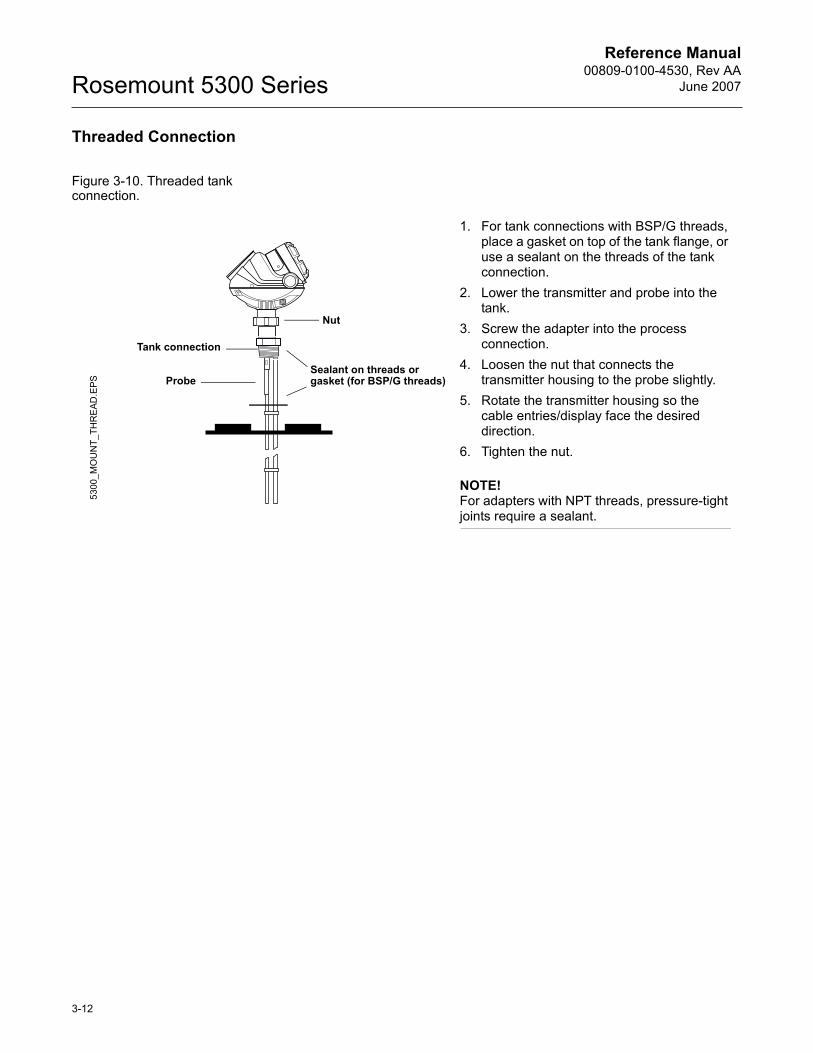
Figure 3-10. Threaded tank connection.
1. For tank connections with BSP/G threads, place a gasket on top of the tank flange, or use a sealant on the threads of the tank connection.
2. Lower the transmitter and probe into the tank.
3. Screw the adapter into the process connection.
4. Loosen the nut that connects the transmitter housing to the probe slightly.
5. Rotate the transmitter housing so the cable entries/display face the desired direction.
6. Tighten the nut.
NOTE!For adapters with NPT threads, pressure-tight joints require a sealant.
Sealant on threads or gasket (for BSP/G threads)
Nut
Tank connection
Probe
5300
_MO
UN
T_TH
RE
AD.E
PS
3-12
Reference Manual 00809-0100-4530, Rev AAJune 2007 Rosemount 5300 Series
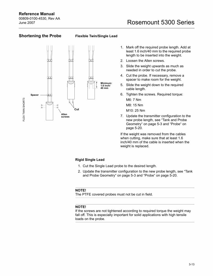
Shortening the Probe Flexible Twin/Single Lead
Rigid Single Lead
1. Cut the Single Lead probe to the desired length.2. Update the transmitter configuration to the new probe length, see �Tank
and Probe Geometry� on page 5-3 and �Probe� on page 5-20.
NOTE!The PTFE covered probes must not be cut in field.
NOTE!If the screws are not tightened according to required torque the weight may fall off. This is especially important for solid applications with high tensile loads on the probe.
1. Mark off the required probe length. Add at least 1.6 inch/40 mm to the required probe length to be inserted into the weight.
2. Loosen the Allen screws. 3. Slide the weight upwards as much as
needed in order to cut the probe.4. Cut the probe. If necessary, remove a
spacer to make room for the weight.5. Slide the weight down to the required
cable length.6. Tighten the screws. Required torque:
M6: 7 NmM8: 15 NmM10: 25 Nm
7. Update the transmitter configuration to the new probe length, see �Tank and Probe Geometry� on page 5-3 and �Probe� on page 5-20.
If the weight was removed from the cables when cutting, make sure that at least 1.6 inch/40 mm of the cable is inserted when the weight is replaced.
Allen screws
Minimum:1.6 inch/40 mm
Spacer
Cut
FLE
X T
WIN
SH
OR
T3
3-13
Reference Manual00809-0100-4530, Rev AA
June 2007Rosemount 5300 Series
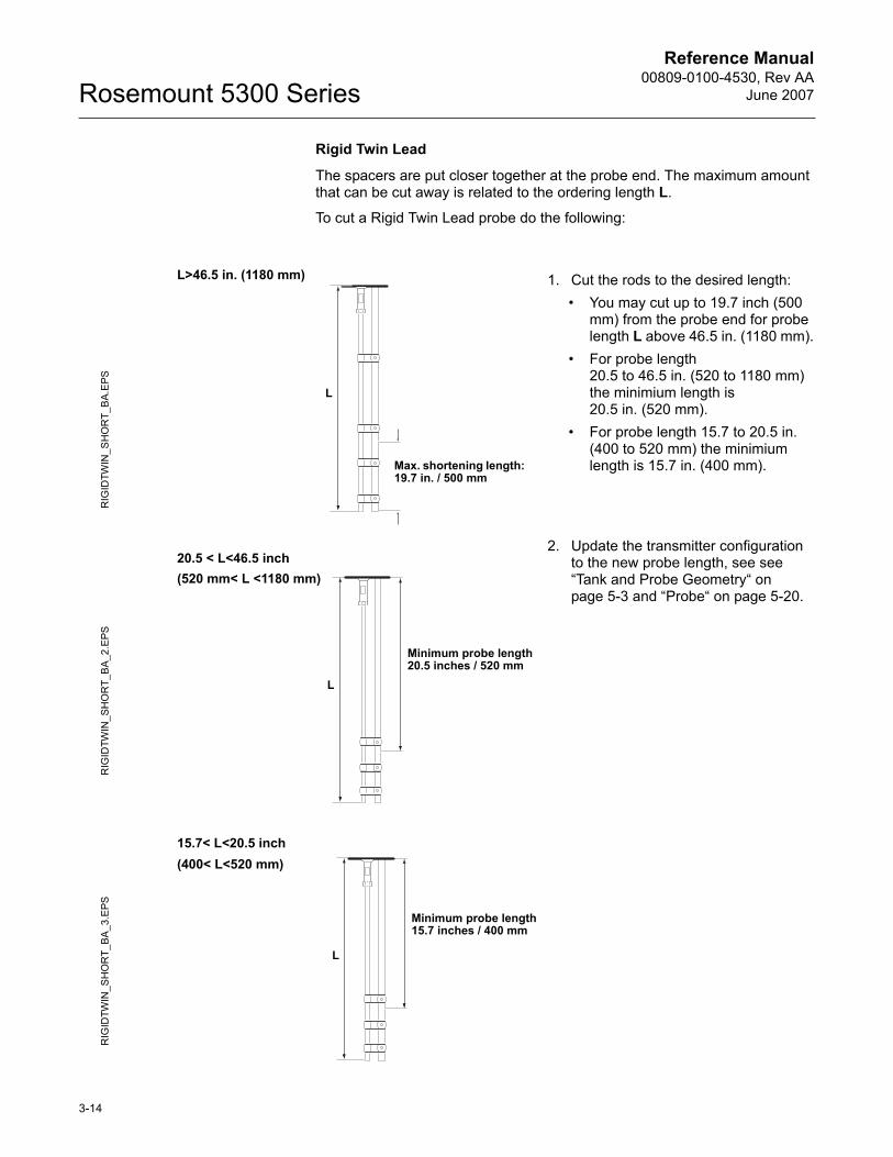
Rigid Twin Lead
The spacers are put closer together at the probe end. The maximum amount that can be cut away is related to the ordering length L.
To cut a Rigid Twin Lead probe do the following:
1. Cut the rods to the desired length:� You may cut up to 19.7 inch (500
mm) from the probe end for probe length L above 46.5 in. (1180 mm).
� For probe length 20.5 to 46.5 in. (520 to 1180 mm) the minimium length is 20.5 in. (520 mm).
� For probe length 15.7 to 20.5 in. (400 to 520 mm) the minimium length is 15.7 in. (400 mm).
2. Update the transmitter configuration to the new probe length, see see �Tank and Probe Geometry� on page 5-3 and �Probe� on page 5-20.
Max. shortening length: 19.7 in. / 500 mm
RIG
IDTW
IN_S
HO
RT_
BA
.EPS
L>46.5 in. (1180 mm)
L
RIG
IDTW
IN_S
HO
RT_
BA_
2.E
PS
20.5 < L<46.5 inch
Minimum probe length20.5 inches / 520 mm
L
(520 mm< L <1180 mm)
RIG
IDTW
IN_S
HO
RT_
BA_3
.EPS
Minimum probe length15.7 inches / 400 mm
L
15.7< L<20.5 inch(400< L<520 mm)
3-14
Reference Manual 00809-0100-4530, Rev AAJune 2007 Rosemount 5300 Series
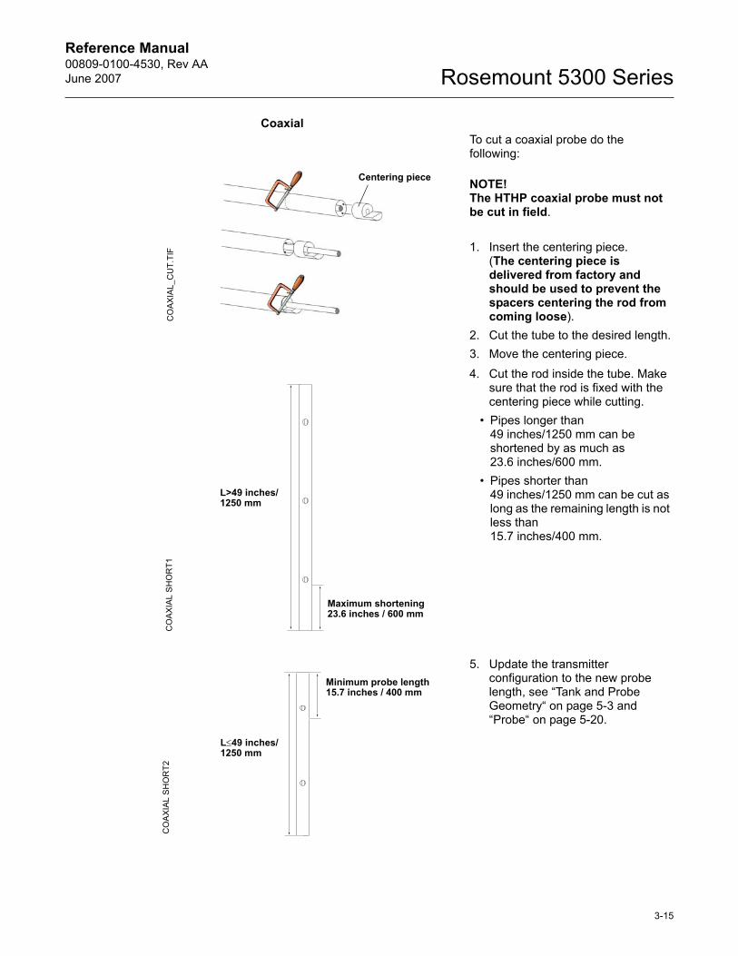
CoaxialTo cut a coaxial probe do the following:
NOTE!The HTHP coaxial probe must not be cut in field.
1. Insert the centering piece.(The centering piece is delivered from factory and should be used to prevent the spacers centering the rod from coming loose).
2. Cut the tube to the desired length.3. Move the centering piece.4. Cut the rod inside the tube. Make
sure that the rod is fixed with the centering piece while cutting.
� Pipes longer than 49 inches/1250 mm can be shortened by as much as 23.6 inches/600 mm.
� Pipes shorter than 49 inches/1250 mm can be cut as long as the remaining length is not less than 15.7 inches/400 mm.
5. Update the transmitter configuration to the new probe length, see �Tank and Probe Geometry� on page 5-3 and �Probe� on page 5-20.
CO
AX
IAL_
CU
T.TI
FCentering piece
Maximum shortening 23.6 inches / 600 mm
L>49 inches/1250 mm
CO
AX
IAL
SH
OR
T1
Minimum probe length15.7 inches / 400 mm
L≤49 inches/1250 mm
CO
AX
IAL
SH
OR
T2
3-15
Reference Manual00809-0100-4530, Rev AA
June 2007Rosemount 5300 Series
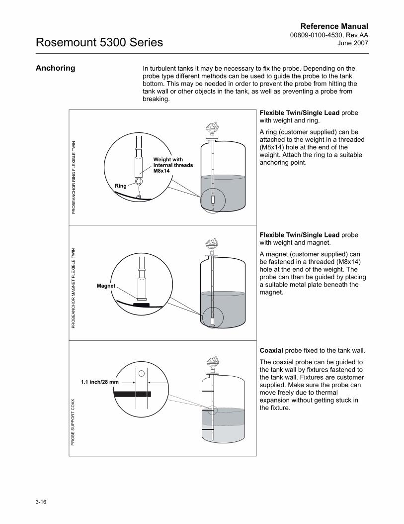
Anchoring In turbulent tanks it may be necessary to fix the probe. Depending on the probe type different methods can be used to guide the probe to the tank bottom. This may be needed in order to prevent the probe from hitting the tank wall or other objects in the tank, as well as preventing a probe from breaking.
Flexible Twin/Single Lead probe with weight and ring.
A ring (customer supplied) can be attached to the weight in a threaded (M8x14) hole at the end of the weight. Attach the ring to a suitable anchoring point.
Flexible Twin/Single Lead probe with weight and magnet.
A magnet (customer supplied) can be fastened in a threaded (M8x14) hole at the end of the weight. The probe can then be guided by placing a suitable metal plate beneath the magnet.
Coaxial probe fixed to the tank wall.
The coaxial probe can be guided to the tank wall by fixtures fastened to the tank wall. Fixtures are customer supplied. Make sure the probe can move freely due to thermal expansion without getting stuck in the fixture.
Weight with internal threadsM8x14
Ring
PRO
BEA
NC
HO
R R
ING
FLE
XIB
LE T
WIN
Magnet
PR
OB
EA
NC
HO
R M
AG
NE
T FL
EXI
BLE
TW
IN
1.1 inch/28 mm
PRO
BE
SU
PP
OR
T C
OA
X
3-16
Reference Manual 00809-0100-4530, Rev AAJune 2007 Rosemount 5300 Series
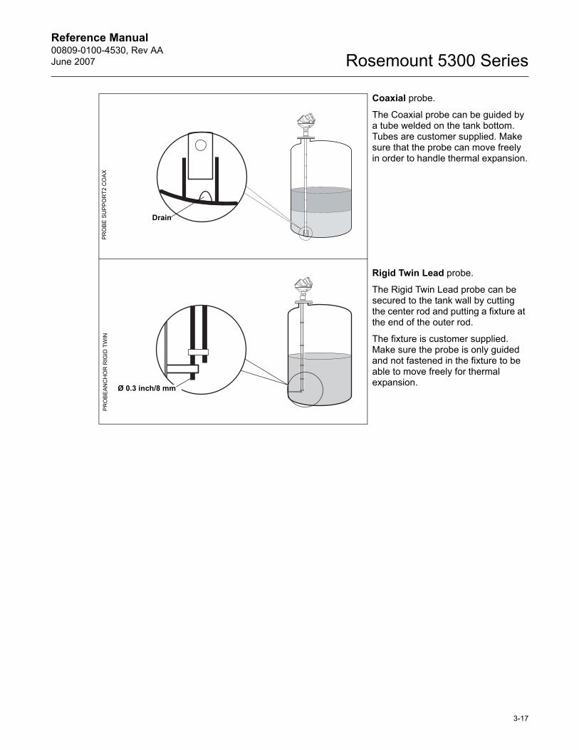
Coaxial probe.
The Coaxial probe can be guided by a tube welded on the tank bottom. Tubes are customer supplied. Make sure that the probe can move freely in order to handle thermal expansion.
Rigid Twin Lead probe.
The Rigid Twin Lead probe can be secured to the tank wall by cutting the center rod and putting a fixture at the end of the outer rod.
The fixture is customer supplied. Make sure the probe is only guided and not fastened in the fixture to be able to move freely for thermal expansion.
Drain
PR
OB
E S
UP
PO
RT2
CO
AX
Ø 0.3 inch/8 mm
PR
OB
EAN
CH
OR
RIG
ID T
WIN
3-17
Reference Manual00809-0100-4530, Rev AA
June 2007Rosemount 5300 Series
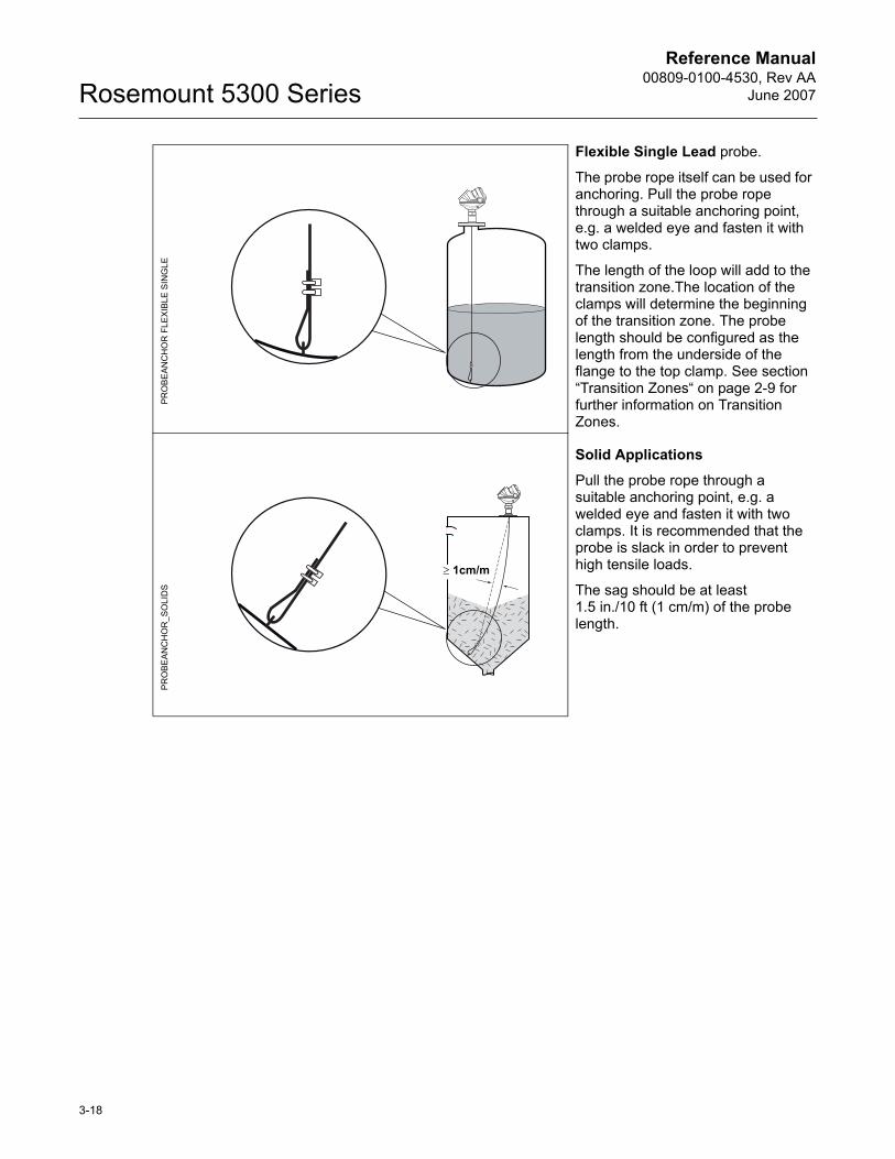
Flexible Single Lead probe.
The probe rope itself can be used for anchoring. Pull the probe rope through a suitable anchoring point, e.g. a welded eye and fasten it with two clamps.
The length of the loop will add to the transition zone.The location of the clamps will determine the beginning of the transition zone. The probe length should be configured as the length from the underside of the flange to the top clamp. See section �Transition Zones� on page 2-9 for further information on Transition Zones.
Solid Applications
Pull the probe rope through a suitable anchoring point, e.g. a welded eye and fasten it with two clamps. It is recommended that the probe is slack in order to prevent high tensile loads.
The sag should be at least 1.5 in./10 ft (1 cm/m) of the probe length.
PR
OB
EAN
CH
OR
FLE
XIB
LE S
ING
LEP
RO
BEA
NC
HO
R_S
OLI
DS
≥ 1cm/m
3-18
Reference Manual 00809-0100-4530, Rev AAJune 2007 Rosemount 5300 Series
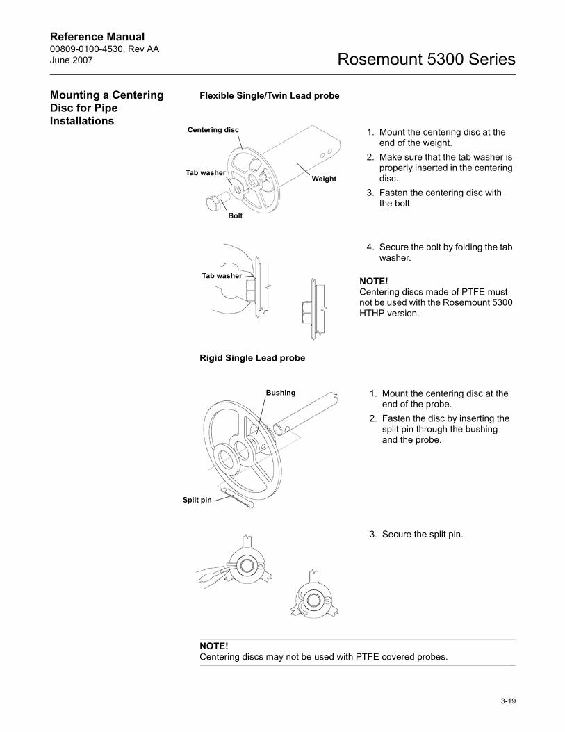
Mounting a Centering Disc for Pipe Installations
Flexible Single/Twin Lead probe
Rigid Single Lead probe
NOTE!Centering discs may not be used with PTFE covered probes.
1. Mount the centering disc at the end of the weight.
2. Make sure that the tab washer is properly inserted in the centering disc.
3. Fasten the centering disc with the bolt.
4. Secure the bolt by folding the tab washer.
NOTE!Centering discs made of PTFE must not be used with the Rosemount 5300 HTHP version.
Centering disc
Weight
Bolt
Tab washer
Tab washer
1. Mount the centering disc at the end of the probe.
2. Fasten the disc by inserting the split pin through the bushing and the probe.
3. Secure the split pin.
Bushing
Split pin
3-19

Reference Manual00809-0100-4530, Rev AA
June 2007Rosemount 5300 Series
3-20
Reference Manual 00809-0100-4530, Rev AAJune 2007 Rosemount 5300 Series
Section 4 Electrical Installation
Safety messages . . . . . . . . . . . . . . . . . . . . . . . . . . . . . . . . . page 4-1Cable/conduit entries . . . . . . . . . . . . . . . . . . . . . . . . . . . . . page 4-3Grounding . . . . . . . . . . . . . . . . . . . . . . . . . . . . . . . . . . . . . . page 4-3Cable Selection . . . . . . . . . . . . . . . . . . . . . . . . . . . . . . . . . . page 4-3Hazardous Areas . . . . . . . . . . . . . . . . . . . . . . . . . . . . . . . . page 4-3HART . . . . . . . . . . . . . . . . . . . . . . . . . . . . . . . . . . . . . . . . . . page 4-4FOUNDATION� Fieldbus . . . . . . . . . . . . . . . . . . . . . . . . . . . . page 4-8Optional Devices . . . . . . . . . . . . . . . . . . . . . . . . . . . . . . . . . page 4-13
SAFETY MESSAGES Procedures and instructions in this section may require special precautions to ensure the safety of the personnel performing the operations. Information that raises potential safety issues is indicated by a warning symbol ( ). Please refer to the following safety messages before performing an operation preceded by this symbol.
Explosions could result in death or serious injury:Verify that the operating environment of the transmitter is consistent with the appropriate hazardous locations certifications.
Before connecting a HART-based communicator in an explosive atmosphere, make sure the instruments in the loop are installed in accordance with intrinsically safe or non-incendive field wiring practices.
Do not remove the gauge cover in explosive atmospheres when the circuit is alive.
Failure to follow safe installation and servicing guidelines could result in death or serious injury:Make sure only qualified personnel perform the installation.
Use the equipment only as specified in this manual. Failure to do so may impair the protection provided by the equipment.
Do not perform any service other than those contained in this manual unless you are qualified.
Process leaks could result in death or serious injury.Make sure that the transmitter is handled carefully. If the Process Seal is damaged, gas might escape from the tank if the transmitter head is removed from the probe.
www.rosemount.com

Reference Manual00809-0100-4530, Rev AA
June 2007Rosemount 5300 Series
High voltage that may be present on leads could cause electrical shock:Avoid contact with leads and terminals.
Make sure the main power to the 5300 transmitter is off and the lines to any other external power source are disconnected or not powered while wiring the gauge.
Probes covered with plastic and/or with plastic discs may generate an ignition-capable level of electrostatic charge under certain extreme conditions. Therefore, when the probe is used in a potentially explosive atmosphere, appropriate measures must be taken to prevent electrostatic discharge.
4-2
Reference Manual 00809-0100-4530, Rev AAJune 2007 Rosemount 5300 Series
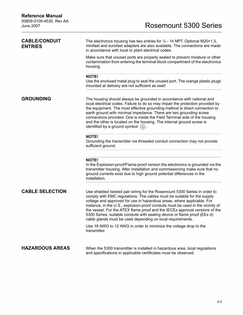
CABLE/CONDUIT ENTRIES
The electronics housing has two entries for ½ - 14 NPT. Optional M20×1.5, minifast and eurofast adapters are also available. The connections are made in accordance with local or plant electrical codes.
Make sure that unused ports are properly sealed to prevent moisture or other contamination from entering the terminal block compartment of the electronics housing.
NOTE!Use the enclosed metal plug to seal the unused port. The orange plastic plugs mounted at delivery are not sufficient as seal!
GROUNDING The housing should always be grounded in accordance with national and local electrical codes. Failure to do so may impair the protection provided by the equipment. The most effective grounding method is direct connection to earth ground with minimal impedance. There are two grounding screw connections provided. One is inside the Field Terminal side of the housing and the other is located on the housing. The internal ground screw is identified by a ground symbol: .
NOTE!Grounding the transmitter via threaded conduit connection may not provide sufficient ground.
NOTE!In the Explosion-proof/Flame-proof version the electronics is grounded via the transmitter housing. After installation and commissioning make sure that no ground currents exist due to high ground potential differences in the installation.
CABLE SELECTION Use shielded twisted pair wiring for the Rosemount 5300 Series in order to comply with EMC regulations. The cables must be suitable for the supply voltage and approved for use in hazardous areas, where applicable. For instance, in the U.S., explosion-proof conduits must be used in the vicinity of the vessel. For the ATEX flame proof and the IECEx approval versions of the 5300 Series, suitable conduits with sealing device or flame proof (EEx d) cable glands must be used depending on local requirements.
Use 18 AWG to 12 AWG in order to minimize the voltage drop to the transmitter.
HAZARDOUS AREAS When the 5300 transmitter is installed in hazardous area, local regulations and specifications in applicable certificates must be observed.
4-3
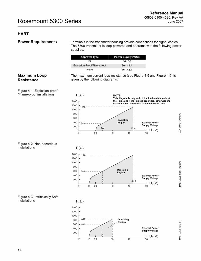
Reference Manual00809-0100-4530, Rev AA
June 2007Rosemount 5300 Series
HART
Power Requirements Terminals in the transmitter housing provide connections for signal cables. The 5300 transmitter is loop-powered and operates with the following power supplies:
Maximum Loop Resistance
The maximum current loop resistance (see Figure 4-5 and Figure 4-6) is given by the following diagrams:
Figure 4-1. Explosion-proof /Flame-proof installations
Figure 4-2. Non-hazardous installations
Figure 4-3. Intrinsically Safe installations
Approval Type Power Supply (VDC)IS 16 - 30
Explosion-Proof/Flameproof 20 - 42.4None 16 - 42.4
MAX
_LO
AD
_EX
D.E
PS
External Power Supply Voltage
NOTEThis diagram is only valid if the load resistance is at the + side and if the - side is grounded, otherwise the maximum load resistance is limited to 435 Ohm.
Operating Region
MAX
_LO
AD
_NO
N_H
AZ.
EPS
External Power Supply Voltage
Operating Region
MAX
_LO
AD
_IS
.EPS
External Power Supply Voltage
Operating Region
4-4
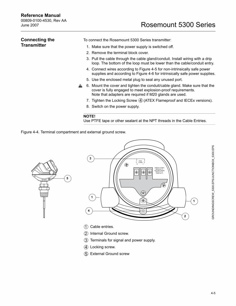
Reference Manual 00809-0100-4530, Rev AAJune 2007 Rosemount 5300 Series
Connecting the Transmitter
To connect the Rosemount 5300 Series transmitter:
1. Make sure that the power supply is switched off.2. Remove the terminal block cover.3. Pull the cable through the cable gland/conduit. Install wiring with a drip
loop. The bottom of the loop must be lower than the cable/conduit entry.4. Connect wires according to Figure 4-5 for non-intrinsically safe power
supplies and according to Figure 4-6 for intrinsically safe power supplies.5. Use the enclosed metal plug to seal any unused port.6. Mount the cover and tighten the conduit/cable gland. Make sure that the
cover is fully engaged to meet explosion-proof requirements.Note that adapters are required if M20 glands are used.
7. Tighten the Locking Screw (ATEX Flameproof and IECEx versions).8. Switch on the power supply.
NOTE!Use PTFE tape or other sealant at the NPT threads in the Cable Entries.
Figure 4-4. Terminal compartment and external ground screw.
Cable entries.
Internal Ground screw.
Terminals for signal and power supply.
Locking screw.
External Ground screw
GR
OU
ND
ING
SC
RE
W_5
300.
EPS
/JU
NC
TIO
NBO
X_5
300.
EPS
11
3
2
5
4
4-5
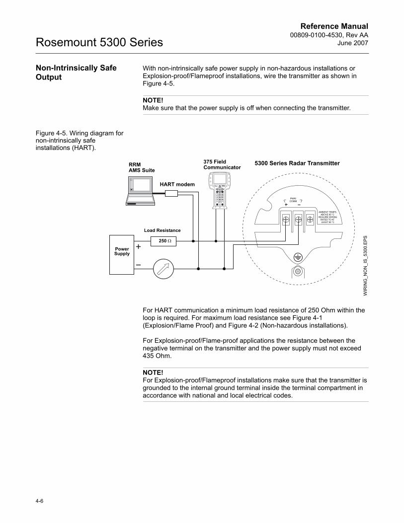
Reference Manual00809-0100-4530, Rev AA
June 2007Rosemount 5300 Series
Non-Intrinsically Safe Output
With non-intrinsically safe power supply in non-hazardous installations or Explosion-proof/Flameproof installations, wire the transmitter as shown in Figure 4-5.
NOTE!Make sure that the power supply is off when connecting the transmitter.
Figure 4-5. Wiring diagram for non-intrinsically safe installations (HART).
For HART communication a minimum load resistance of 250 Ohm within the loop is required. For maximum load resistance see Figure 4-1 (Explosion/Flame Proof) and Figure 4-2 (Non-hazardous installations).
For Explosion-proof/Flame-proof applications the resistance between the negative terminal on the transmitter and the power supply must not exceed 435 Ohm.
NOTE!For Explosion-proof/Flameproof installations make sure that the transmitter is grounded to the internal ground terminal inside the terminal compartment in accordance with national and local electrical codes.
Load Resistance
Power Supply
375 Field Communicator
5300 Series Radar Transmitter
HART modem
RRMAMS Suite
WIR
ING
_NO
N_I
S_5
300.
EPS250 Ω
4-6
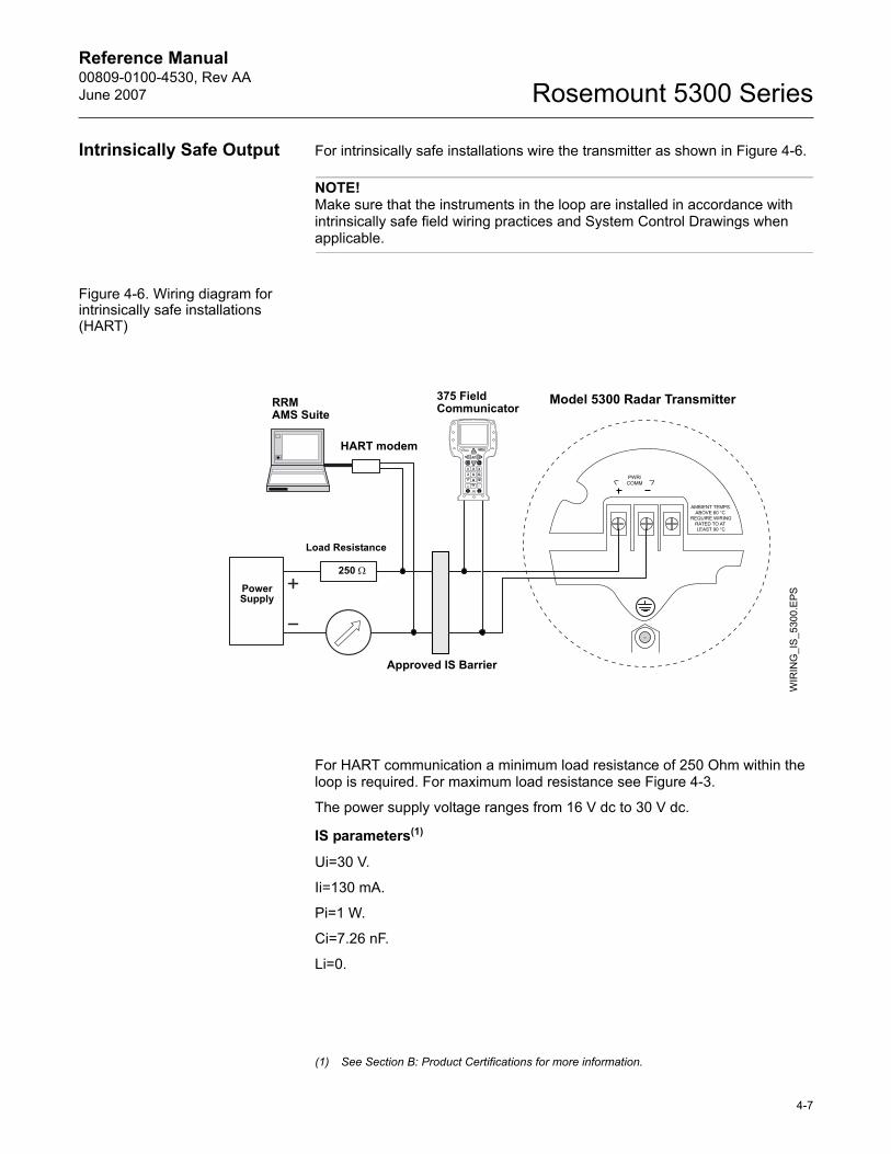
Reference Manual 00809-0100-4530, Rev AAJune 2007 Rosemount 5300 Series
Intrinsically Safe Output For intrinsically safe installations wire the transmitter as shown in Figure 4-6.
NOTE!Make sure that the instruments in the loop are installed in accordance with intrinsically safe field wiring practices and System Control Drawings when applicable.
Figure 4-6. Wiring diagram for intrinsically safe installations (HART)
For HART communication a minimum load resistance of 250 Ohm within the loop is required. For maximum load resistance see Figure 4-3.
The power supply voltage ranges from 16 V dc to 30 V dc.
IS parameters(1)
Ui=30 V.
Ii=130 mA.
Pi=1 W.
Ci=7.26 nF.
Li=0.
Load Resistance
Power Supply
375 Field Communicator
Model 5300 Radar Transmitter
HART modem
RRMAMS Suite
WIR
ING
_IS
_530
0.E
PS
250 Ω
Approved IS Barrier
(1) See Section B: Product Certifications for more information.
4-7
Reference Manual00809-0100-4530, Rev AA
June 2007Rosemount 5300 Series
FOUNDATION� FIELDBUS
Power Requirements Terminals in the transmitter housing provide connections for signal cables. The 5300 transmitter is powered over FOUNDATION fieldbus with standard fielbus power supplies. The transmitter operates with the following power supplies:
Connecting the Transmitter
To connect the transmitter:
1. Make sure that the power supply is switched off.2. Remove the terminal block cover.3. Pull the cable through the cable gland/conduit. Install wiring with a drip
loop. The bottom of the loop must be lower than the cable/conduit entry.4. Connect wires according to Figure 4-9 for non-intrinsically safe power
supplies and according to Figure 4-10 for intrinsically safe power supplies.
5. Use the enclosed metal plug to seal any unused port.6. Mount the cover and tighten the conduit/cable gland. Make sure that the
cover is fully engaged to meet explosion-proof requirements.Note that adapters are required if M20 glands are used.
7. Tighten the Locking Screw (ATEX Flameproof and IECEx versions).8. Switch on the power supply.
NOTE!Use PTFE tape or other sealant at the NPT threads in the Cable Entries.
Approval Type Power Supply (VDC)IS 9 - 30
Explosion-Proof/Flameproof 16 - 32None 9 - 32
FISCO; IS 9 - 17.5
4-8
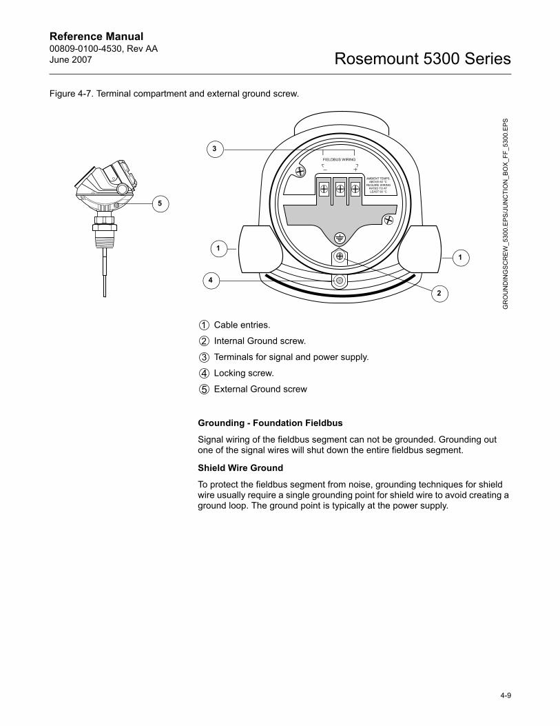
Reference Manual 00809-0100-4530, Rev AAJune 2007 Rosemount 5300 Series
Figure 4-7. Terminal compartment and external ground screw.
Cable entries.
Internal Ground screw.
Terminals for signal and power supply.
Locking screw.
External Ground screw
Grounding - Foundation Fieldbus
Signal wiring of the fieldbus segment can not be grounded. Grounding out one of the signal wires will shut down the entire fieldbus segment.
Shield Wire Ground
To protect the fieldbus segment from noise, grounding techniques for shield wire usually require a single grounding point for shield wire to avoid creating a ground loop. The ground point is typically at the power supply.
GR
OU
ND
ING
SC
RE
W_5
300.
EP
S/J
UN
CTI
ON
_BO
X_F
F_53
00.E
PS
11
3
2
5
4
4-9
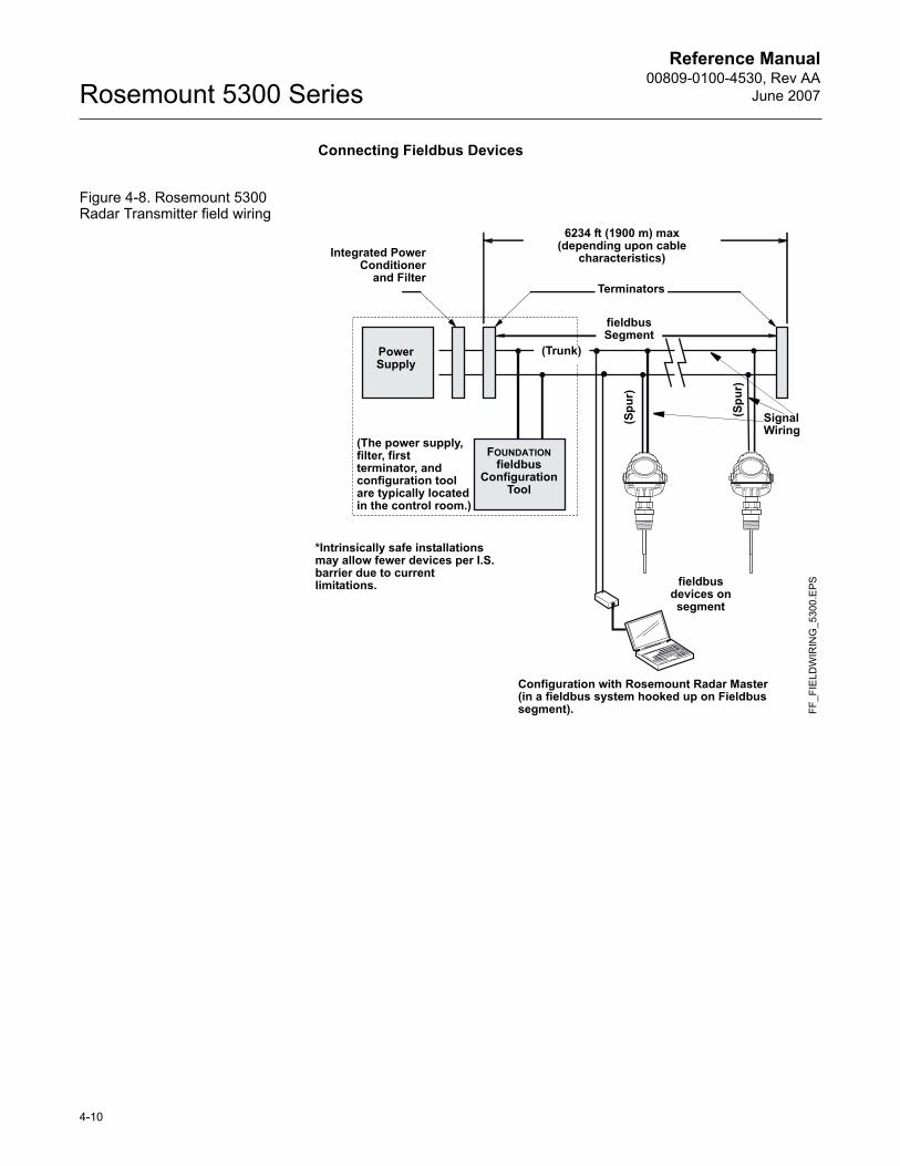
Reference Manual00809-0100-4530, Rev AA
June 2007Rosemount 5300 Series
Connecting Fieldbus Devices
Figure 4-8. Rosemount 5300 Radar Transmitter field wiring
FF_F
IELD
WIR
ING
_530
0.E
PS
Signal Wiring
Power Supply
FOUNDATION fieldbus
Configuration Tool
Terminators
6234 ft (1900 m) max(depending upon cable
characteristics)Integrated PowerConditioner
and Filter
(Trunk)
(Spu
r)
(Spu
r)
(The power supply, filter, first terminator, and configuration tool are typically located in the control room.)
fieldbus Segment
fieldbus devices on segment
*Intrinsically safe installations may allow fewer devices per I.S. barrier due to current limitations.
Configuration with Rosemount Radar Master(in a fieldbus system hooked up on Fieldbus segment).
4-10
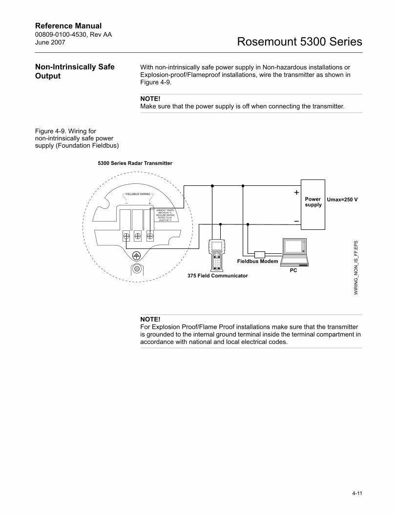
Reference Manual 00809-0100-4530, Rev AAJune 2007 Rosemount 5300 Series
Non-Intrinsically Safe Output
With non-intrinsically safe power supply in Non-hazardous installations or Explosion-proof/Flameproof installations, wire the transmitter as shown in Figure 4-9.
NOTE!Make sure that the power supply is off when connecting the transmitter.
Figure 4-9. Wiring for non-intrinsically safe power supply (Foundation Fieldbus)
NOTE!For Explosion Proof/Flame Proof installations make sure that the transmitter is grounded to the internal ground terminal inside the terminal compartment in accordance with national and local electrical codes.
Power supply
WIR
ING
_NO
N_I
S_F
F.E
PS
375 Field Communicator
5300 Series Radar Transmitter
PC
Umax=250 V
Fieldbus Modem
4-11
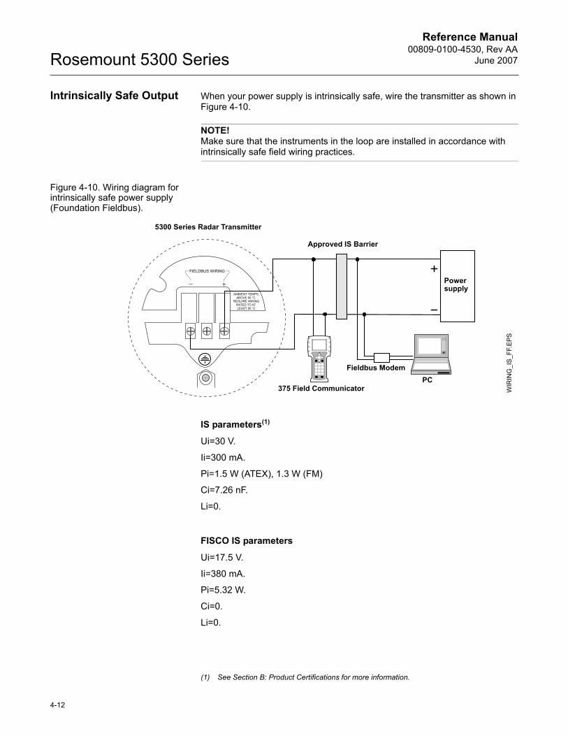
Reference Manual00809-0100-4530, Rev AA
June 2007Rosemount 5300 Series
Intrinsically Safe Output When your power supply is intrinsically safe, wire the transmitter as shown in Figure 4-10.
NOTE!Make sure that the instruments in the loop are installed in accordance with intrinsically safe field wiring practices.
Figure 4-10. Wiring diagram for intrinsically safe power supply (Foundation Fieldbus).
IS parameters(1)
Ui=30 V.
Ii=300 mA.
Pi=1.5 W (ATEX), 1.3 W (FM)
Ci=7.26 nF.
Li=0.
FISCO IS parameters
Ui=17.5 V.
Ii=380 mA.
Pi=5.32 W.
Ci=0.
Li=0.
Power supply
WIR
ING
_IS
_FF.
EPS
5300 Series Radar Transmitter
Approved IS Barrier
375 Field CommunicatorPC
Fieldbus Modem
(1) See Section B: Product Certifications for more information.
4-12
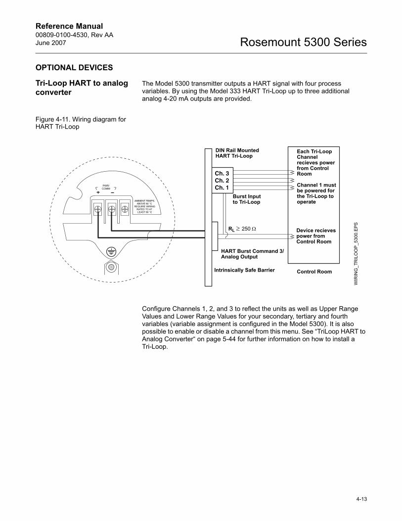
Reference Manual 00809-0100-4530, Rev AAJune 2007 Rosemount 5300 Series
OPTIONAL DEVICES
Tri-Loop HART to analog converter
The Model 5300 transmitter outputs a HART signal with four process variables. By using the Model 333 HART Tri-Loop up to three additional analog 4-20 mA outputs are provided.
Figure 4-11. Wiring diagram for HART Tri-Loop
Configure Channels 1, 2, and 3 to reflect the units as well as Upper Range Values and Lower Range Values for your secondary, tertiary and fourth variables (variable assignment is configured in the Model 5300). It is also possible to enable or disable a channel from this menu. See �TriLoop HART to Analog Converter� on page 5-44 for further information on how to install a Tri-Loop.
Ch. 3Ch. 2Ch. 1
Each Tri-Loop Channel recieves power from Control Room
Channel 1 must be powered for the Tri-Loop to operate
Device recieves power from Control Room
RL ≥ 250 Ω
HART Burst Command 3/Analog Output
Intrinsically Safe Barrier
DIN Rail MountedHART Tri-Loop
Control Room
WIR
ING
_TR
ILO
OP_
5300
.EPS
Burst Input to Tri-Loop
4-13
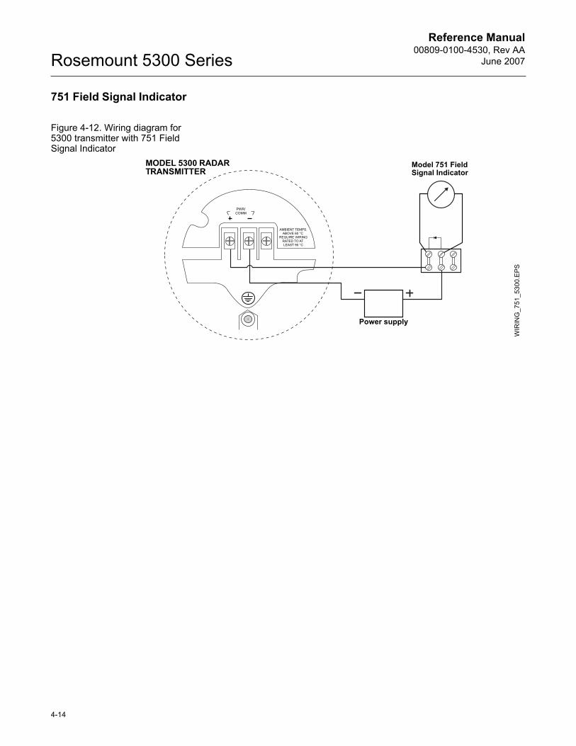
Reference Manual00809-0100-4530, Rev AA
June 2007Rosemount 5300 Series
751 Field Signal Indicator
Figure 4-12. Wiring diagram for 5300 transmitter with 751 Field Signal Indicator
Power supply
WIR
ING
_751
_530
0.EP
S
MODEL 5300 RADAR TRANSMITTER
Model 751 Field Signal Indicator
4-14
Reference Manual 00809-0100-4530, Rev AAJune 2007 Rosemount 5300 Series
Section 5 Configuration
Safety messages . . . . . . . . . . . . . . . . . . . . . . . . . . . . . . . . . page 5-1Overview . . . . . . . . . . . . . . . . . . . . . . . . . . . . . . . . . . . . . . . page 5-2Basic Configuration Parameters . . . . . . . . . . . . . . . . . . . . page 5-3Basic Configuration using a 375 Field Communicator . . page 5-10Basic Configuration Using Rosemount Radar Master . . page 5-12Basic Configuration Using AMS Suite (HART) . . . . . . . . page 5-29Basic Configuration Using DeltaV . . . . . . . . . . . . . . . . . . page 5-30FOUNDATION Fieldbus Overview . . . . . . . . . . . . . . . . . . . . . page 5-35Configure the AI Block . . . . . . . . . . . . . . . . . . . . . . . . . . . . page 5-38TriLoop HART to Analog Converter . . . . . . . . . . . . . . . . . page 5-44HART Multi-drop Configuration . . . . . . . . . . . . . . . . . . . . . page 5-46
SAFETY MESSAGES Procedures and instructions in this section may require special precautions to ensure the safety of the personnel performing the operations. Information that raises potential safety issues is indicated by a warning symbol ( ). Refer to the safety messages listed at the beginning of each section before performing an operation preceded by this symbol.
Explosions could result in death or serious injury:Verify that the operating environment of the gauge is consistent with the appropriate hazardous locations certifications.
Before connecting a HART-based communicator in an explosive atmosphere, make sure the instruments in the loop are installed in accordance with intrinsically safe or non-incendive field wiring practices.
Do not remove the gauge cover in explosive atmospheres when the circuit is alive.
Failure to follow safe installation and servicing guidelines could result in death or serious injury:Make sure only qualified personnel perform the installation.
Use the equipment only as specified in this manual. Failure to do so may impair the protection provided by the equipment.
Do not perform any service other than those contained in this manual unless you are qualified.
www.rosemount.com
Reference Manual00809-0100-4530, Rev AA
June 2007Rosemount 5300 Series
OVERVIEW Configuration of a Rosemount 5300 transmitter is normally a simple and straight-forward task. A complete configuration of a Rosemount 5300 transmitter includes Basic Configuration, Echo Tuning and Advanced Configuration. This section describes Basic Configuration.
If the transmitter is pre-configured at factory according to the ordering specifications in the Configuration Data Sheet, no further Basic Configuration is required unless tank conditions have changed. The 5300 Series supports a set of advanced configuration options as well, which can be used to handle special tank conditions and applications.
Basic Configuration The Basic Configuration includes parameters for a standard configuration which is sufficient in most cases. The Basic Configuration comprises the following items:
� Measurement Units� Tank Configuration
- Tank Geometry- Environment- Volume
� Analog Output
Echo Tuning Amplitude thresholds can be adjusted in order to handle special situations when, for example, objects in the tank cause disturbing echoes that are stronger than the surface echo. A useful function is the so called Amplitude Threshold Curve (ATC) which lets you filter out single disturbing echoes. See Section 7: Service and Troubleshooting, and Section C: Advanced Configuration for more information.
LCD Configuration It is possible to specify the variables to be presented on the Display Panel. See also Section 6: Operation.
Advanced Configuration For some applications further configuration is needed in addition to the Basic Configuration. This may be due to the properties of the product or the shape of the tank. See Appendix C: Advanced Configuration for more information.
Configuration Tools There are several tools available for basic configuration of a 5300 transmitter:� Rosemount Radar Master (RRM). Note that RRM is recommended for
advanced configuration features. See �Basic Configuration Using Rosemount Radar Master� on page 5-12 for information on how to use RRM for configuration of the 5300 Series.
� Rosemount 375 Field Communicator.See �Basic Configuration using a 375 Field Communicator� on page 5-10 for the Field Communicator Menu Tree.
� AMS Suite software (for HART). See �Basic Configuration Using AMS Suite (HART)� on page 5-29.
� DeltaV (only for Foundation Fieldbus). See �Basic Configuration Using DeltaV� on page 5-30.
� Other tools that support Electronic Device Description Language (EDDL) functionality.
5-2
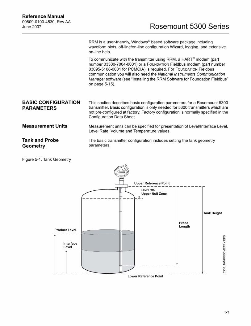
Reference Manual 00809-0100-4530, Rev AAJune 2007 Rosemount 5300 Series
RRM is a user-friendly, Windows® based software package including waveform plots, off-line/on-line configuration Wizard, logging, and extensive on-line help.
To communicate with the transmitter using RRM, a HART® modem (part number 03300-7004-0001) or a FOUNDATION Fieldbus modem (part number 03095-5108-0001 for PCMCIA) is required. For FOUNDATION Fieldbus communication you will also need the National Instruments Communication Manager software (see �Installing the RRM Software for Foundation Fieldbus� on page 5-15).
BASIC CONFIGURATION PARAMETERS
This section describes basic configuration parameters for a Rosemount 5300 transmitter. Basic configuration is only needed for 5300 transmitters which are not pre-configured at factory. Factory configuration is normally specified in the Configuration Data Sheet.
Measurement Units Measurement units can be specified for presentation of Level/Interface Level, Level Rate, Volume and Temperature values.
Tank and Probe Geometry
The basic transmitter configuration includes setting the tank geometry parameters.
Figure 5-1. Tank Geometry
Tank Height
Hold Off/Upper Null Zone
Product Level
Upper Reference Point
Lower Reference Point
Interface Level
Probe Length
5300
_TAN
KG
EOM
ETR
Y.E
PS
5-3
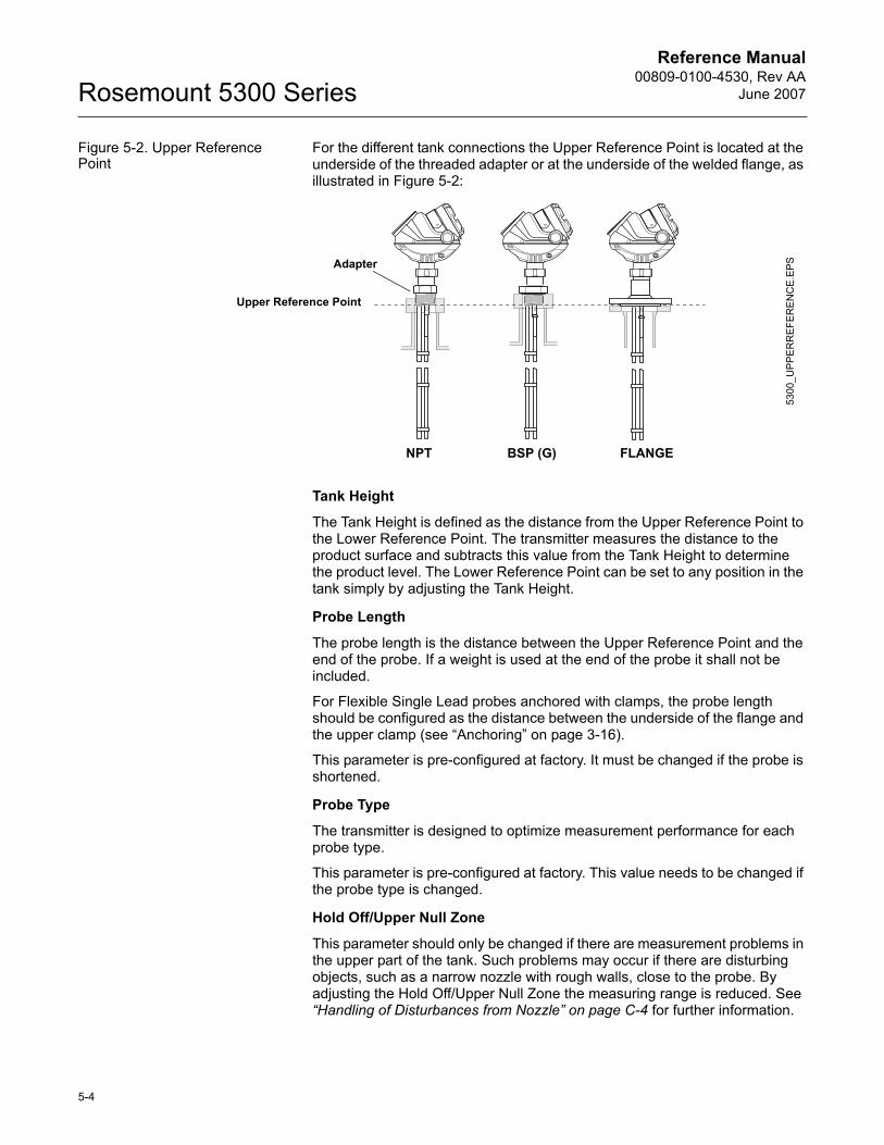
Reference Manual00809-0100-4530, Rev AA
June 2007Rosemount 5300 Series
Figure 5-2. Upper Reference Point
For the different tank connections the Upper Reference Point is located at the underside of the threaded adapter or at the underside of the welded flange, as illustrated in Figure 5-2:
Tank Height
The Tank Height is defined as the distance from the Upper Reference Point to the Lower Reference Point. The transmitter measures the distance to the product surface and subtracts this value from the Tank Height to determine the product level. The Lower Reference Point can be set to any position in the tank simply by adjusting the Tank Height.
Probe Length
The probe length is the distance between the Upper Reference Point and the end of the probe. If a weight is used at the end of the probe it shall not be included.
For Flexible Single Lead probes anchored with clamps, the probe length should be configured as the distance between the underside of the flange and the upper clamp (see �Anchoring� on page 3-16).
This parameter is pre-configured at factory. It must be changed if the probe is shortened.
Probe Type
The transmitter is designed to optimize measurement performance for each probe type.
This parameter is pre-configured at factory. This value needs to be changed if the probe type is changed.
Hold Off/Upper Null Zone
This parameter should only be changed if there are measurement problems in the upper part of the tank. Such problems may occur if there are disturbing objects, such as a narrow nozzle with rough walls, close to the probe. By adjusting the Hold Off/Upper Null Zone the measuring range is reduced. See �Handling of Disturbances from Nozzle� on page C-4 for further information.
NPT BSP (G) FLANGE
Upper Reference Point
5300
_UP
PE
RR
EFER
EN
CE
.EPSAdapter
5-4
Reference Manual 00809-0100-4530, Rev AAJune 2007 Rosemount 5300 Series
Tank Environment Measurement Mode
Normally the Measurement Mode does not need to be changed. The transmitter is pre-configured according to the specified model:
Submerged is used for applications where the probe is fully submerged in liquid. In this mode the transmitter ignores the upper product level. See �Interface Measurements with Fully Submerged Probes� on page 7-16� for more information.
NOTE!Only use Submerged for applications where the interface is measured with a fully submerged probe.
Rapid Level Changes
Optimize the transmitter for measurement conditions where the level changes quickly due to filling and emptying of the tank. As a default standard a 5300 transmitter is able to track level changes of up to 1.5 inch/s (40 mm/s). When the Rapid Level Changes check box is marked, the transmitter can track level changes of up to 8 inch/s (200 mm/s).
The Rapid Level Changes check box shall not be used in normal conditions when the product surface moves slowly.
Dielectric Constant
For interface measurements the dielectric constant of the upper product is essential in order to obtain good accuracy. See section �Interface� on page 2-11 for further information on dielectric constants. If the dielectric constant of the lower product is significantly smaller than the dielectric constant of water, you may need to make special adjustments, see Appendix C: Advanced Configuration for further information.
For level measurements the Upper Product Dielectric parameter corresponds to the actual dielectric constant of the product in the tank. Normally this parameter does not need to be changed even if the actual dielectric constant of the product deviates from the Upper Product Dielectric parameter value. However, for some products measurement performance can be optimized by setting the proper product dielectric constant.
Table 5-1. List of Measurement Modes which can be used for different 5300 models
Model Measurement Mode5301 � Liquid Product Level(1)
� Interface Level with Submerged probe
(1) Default setting
5302 � Liquid Product Level� Product Level and Interface Level(1)
� Interface Level with Submerged probe� Solid Product Level
5303 � Solid Product Level(1)
5-5
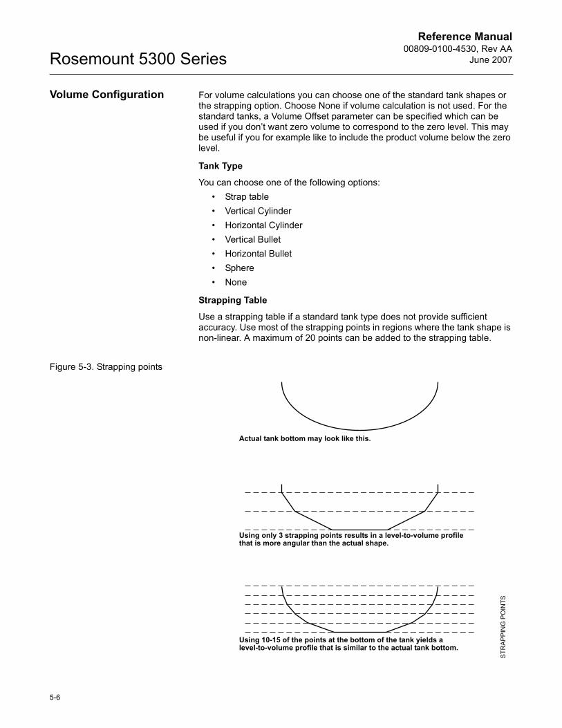
Reference Manual00809-0100-4530, Rev AA
June 2007Rosemount 5300 Series
Volume Configuration For volume calculations you can choose one of the standard tank shapes or the strapping option. Choose None if volume calculation is not used. For the standard tanks, a Volume Offset parameter can be specified which can be used if you don�t want zero volume to correspond to the zero level. This may be useful if you for example like to include the product volume below the zero level.
Tank Type
You can choose one of the following options:� Strap table� Vertical Cylinder� Horizontal Cylinder� Vertical Bullet� Horizontal Bullet� Sphere� None
Strapping Table
Use a strapping table if a standard tank type does not provide sufficient accuracy. Use most of the strapping points in regions where the tank shape is non-linear. A maximum of 20 points can be added to the strapping table.
Figure 5-3. Strapping points
Actual tank bottom may look like this.
Using only 3 strapping points results in a level-to-volume profile that is more angular than the actual shape.
Using 10-15 of the points at the bottom of the tank yields a level-to-volume profile that is similar to the actual tank bottom.
STR
APP
ING
PO
INTS
5-6
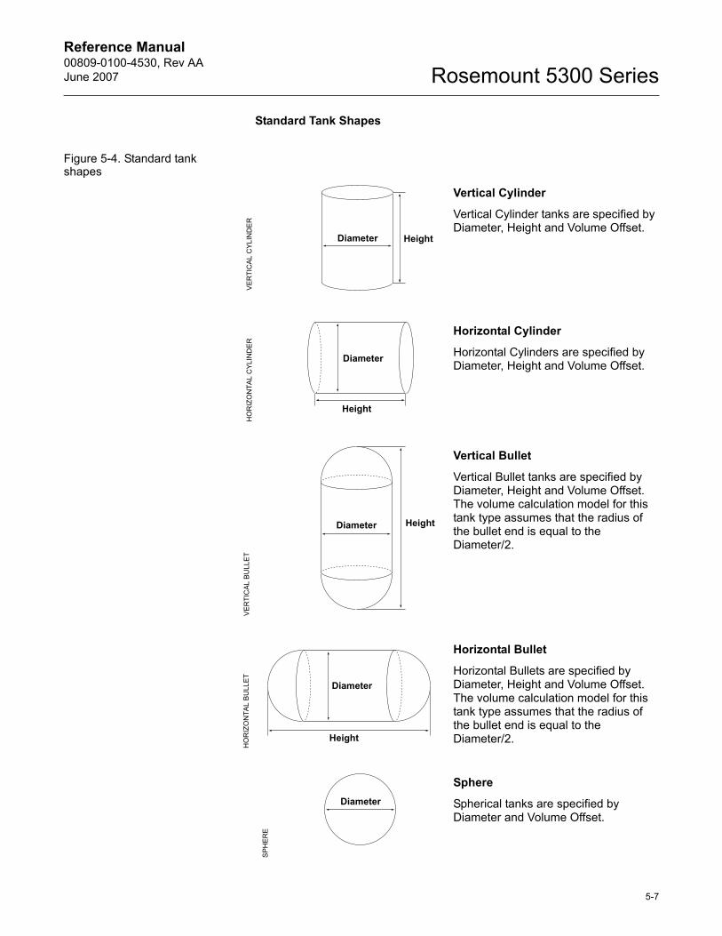
Reference Manual 00809-0100-4530, Rev AAJune 2007 Rosemount 5300 Series
Standard Tank Shapes
Figure 5-4. Standard tank shapes
Vertical Cylinder
Vertical Cylinder tanks are specified by Diameter, Height and Volume Offset.
Horizontal Cylinder
Horizontal Cylinders are specified by Diameter, Height and Volume Offset.
Vertical Bullet
Vertical Bullet tanks are specified by Diameter, Height and Volume Offset. The volume calculation model for this tank type assumes that the radius of the bullet end is equal to the Diameter/2.
Horizontal Bullet
Horizontal Bullets are specified by Diameter, Height and Volume Offset. The volume calculation model for this tank type assumes that the radius of the bullet end is equal to the Diameter/2.
Sphere
Spherical tanks are specified by Diameter and Volume Offset.
Diameter HeightV
ER
TIC
AL C
YLI
ND
ER
Diameter
Height
HO
RIZ
ON
TAL
CYL
IND
ER
Diameter Height
VE
RTI
CA
L B
ULL
ET
Diameter
Height
HO
RIZ
ON
TAL
BU
LLE
T
Diameter
SPH
ER
E
5-7
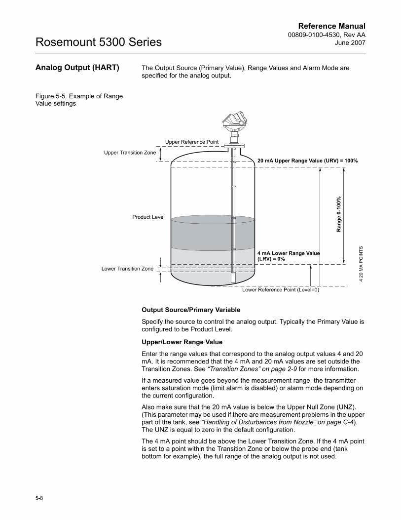
Reference Manual00809-0100-4530, Rev AA
June 2007Rosemount 5300 Series
Analog Output (HART) The Output Source (Primary Value), Range Values and Alarm Mode are specified for the analog output.
Figure 5-5. Example of Range Value settings
Output Source/Primary Variable
Specify the source to control the analog output. Typically the Primary Value is configured to be Product Level.
Upper/Lower Range Value
Enter the range values that correspond to the analog output values 4 and 20 mA. It is recommended that the 4 mA and 20 mA values are set outside the Transition Zones. See �Transition Zones� on page 2-9 for more information.
If a measured value goes beyond the measurement range, the transmitter enters saturation mode (limit alarm is disabled) or alarm mode depending on the current configuration.
Also make sure that the 20 mA value is below the Upper Null Zone (UNZ). (This parameter may be used if there are measurement problems in the upper part of the tank, see �Handling of Disturbances from Nozzle� on page C-4). The UNZ is equal to zero in the default configuration.
The 4 mA point should be above the Lower Transition Zone. If the 4 mA point is set to a point within the Transition Zone or below the probe end (tank bottom for example), the full range of the analog output is not used.
20 mA Upper Range Value (URV) = 100%Upper Transition Zone
Product Level
Lower Transition Zone
4 mA Lower Range Value (LRV) = 0%
Upper Reference Point
Ran
ge 0
-100
%
4 20
MA
PO
INTS
Lower Reference Point (Level=0)
5-8
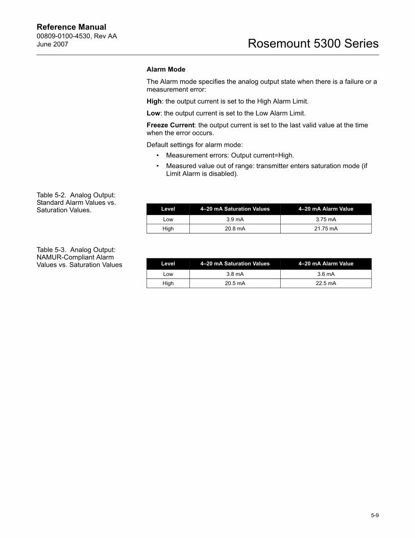
Reference Manual 00809-0100-4530, Rev AAJune 2007 Rosemount 5300 Series
Alarm Mode
The Alarm mode specifies the analog output state when there is a failure or a measurement error:
High: the output current is set to the High Alarm Limit.
Low: the output current is set to the Low Alarm Limit.
Freeze Current: the output current is set to the last valid value at the time when the error occurs.
Default settings for alarm mode:� Measurement errors: Output current=High. � Measured value out of range: transmitter enters saturation mode (if
Limit Alarm is disabled).
Table 5-2. Analog Output: Standard Alarm Values vs. Saturation Values.
Table 5-3. Analog Output: NAMUR-Compliant Alarm Values vs. Saturation Values
Level 4�20 mA Saturation Values 4�20 mA Alarm Value
Low 3.9 mA 3.75 mA
High 20.8 mA 21.75 mA
Level 4�20 mA Saturation Values 4�20 mA Alarm Value
Low 3.8 mA 3.6 mA
High 20.5 mA 22.5 mA
5-9
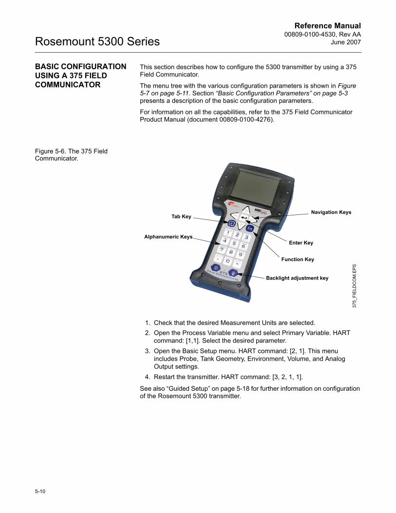
Reference Manual00809-0100-4530, Rev AA
June 2007Rosemount 5300 Series
BASIC CONFIGURATION USING A 375 FIELD COMMUNICATOR
This section describes how to configure the 5300 transmitter by using a 375 Field Communicator.
The menu tree with the various configuration parameters is shown in Figure 5-7 on page 5-11. Section �Basic Configuration Parameters� on page 5-3 presents a description of the basic configuration parameters.
For information on all the capabilities, refer to the 375 Field Communicator Product Manual (document 00809-0100-4276).
Figure 5-6. The 375 Field Communicator.
1. Check that the desired Measurement Units are selected.2. Open the Process Variable menu and select Primary Variable. HART
command: [1,1]. Select the desired parameter.3. Open the Basic Setup menu. HART command: [2, 1]. This menu
includes Probe, Tank Geometry, Environment, Volume, and Analog Output settings.
4. Restart the transmitter. HART command: [3, 2, 1, 1].
See also �Guided Setup� on page 5-18 for further information on configuration of the Rosemount 5300 transmitter.
Function Key
Navigation Keys
Alphanumeric Keys
Backlight adjustment key
375_
FIE
LDC
OM
.EPS
Tab Key
Enter Key
5-10
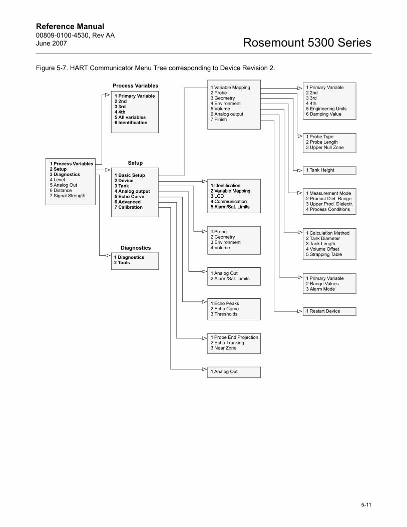
Reference Manual 00809-0100-4530, Rev AAJune 2007 Rosemount 5300 Series
Figure 5-7. HART Communicator Menu Tree corresponding to Device Revision 2.
Process Variables
1 Process Variables2 Setup3 Diagnostics4 Level5 Analog Out6 Distance7 Signal Strength
1 Primary Variable2 2nd3 3rd4 4th5 All variables6 Identification
1 Basic Setup2 Device3 Tank4 Analog output5 Echo Curve6 Advanced7 Calibration
1 Diagnostics2 Tools
1 Variable Mapping2 Probe3 Geometry4 Environment5 Volume6 Analog output7 Finish
1 Identification2 Variable Mapping3 LCD4 Communication5 Alarm/Sat. Limits
1 Identification2 Variable Mapping3 LCD4 Communication5 Alarm/Sat. Limits
1 Probe2 Geometry3 Environment4 Volume
1 Analog Out2 Alarm/Sat. Limits
1 Echo Peaks2 Echo Curve3 Thresholds
1 Probe End Projection2 Echo Tracking3 Near Zone
1 Analog Out
Setup
Diagnostics
1 Primary Variable2 2nd3 3rd4 4th5 Engineering Units6 Damping Value
1 Probe Type2 Probe Length3 Upper Null Zone
1 Tank Height
1 Measurement Mode2 Product Diel. Range3 Upper Prod. Dielectr.4 Process Conditions
1 Calculation Method2 Tank Diameter3 Tank Length4 Volume Offset5 Strapping Table
1 Primary Variable2 Range Values3 Alarm Mode
1 Restart Device
5-11
Reference Manual00809-0100-4530, Rev AA
June 2007Rosemount 5300 Series
BASIC CONFIGURATION USING ROSEMOUNT RADAR MASTER
The Rosemount Radar Master (RRM) is a user-friendly software tool that allows you to configure the Rosemount 5300 transmitter. You can choose either of the following two methods to configure a Rosemount 5300 transmitter with RRM:
� Guided Setup if you are unfamiliar with the 5300 transmitter (see page 5-18).
� Setup functions if you are already familiar with the configuration process or if you just want to change the current settings (page 5-17).
System Requirements Hardware
Processor (minimum/recommended): Pentium 200 MHz/1 GHz
Memory (minimum/recommended): 64/128 MB RAM
COM Port: 1 serial COM port
Graphical Card (minimum/recommended): screen resolution 800 x 600/1024 x 768.
Hard drive space: 100 MB
Software
Operating Systems supported:
Windows 98 - service pack 3 and above
Windows 2000
Windows XP
Help In RRM Help is accessed by selecting the Contents option from the Help menu. Help is also available via a Help button in most windows.
5-12
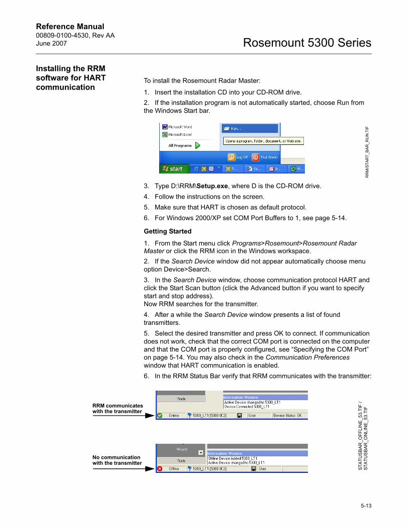
Reference Manual 00809-0100-4530, Rev AAJune 2007 Rosemount 5300 Series
Installing the RRM software for HART communication
To install the Rosemount Radar Master:
1. Insert the installation CD into your CD-ROM drive.2. If the installation program is not automatically started, choose Run from the Windows Start bar.
3. Type D:\RRM\Setup.exe, where D is the CD-ROM drive.4. Follow the instructions on the screen.5. Make sure that HART is chosen as default protocol.6. For Windows 2000/XP set COM Port Buffers to 1, see page 5-14.
Getting Started
1. From the Start menu click Programs>Rosemount>Rosemount Radar Master or click the RRM icon in the Windows workspace. 2. If the Search Device window did not appear automatically choose menu option Device>Search.3. In the Search Device window, choose communication protocol HART and click the Start Scan button (click the Advanced button if you want to specify start and stop address). Now RRM searches for the transmitter.4. After a while the Search Device window presents a list of found transmitters.5. Select the desired transmitter and press OK to connect. If communication does not work, check that the correct COM port is connected on the computer and that the COM port is properly configured, see �Specifying the COM Port� on page 5-14. You may also check in the Communication Preferences window that HART communication is enabled.6. In the RRM Status Bar verify that RRM communicates with the transmitter:
RR
M/S
TAR
T_B
AR_R
UN
.TIF
RRM communicates with the transmitter
No communication with the transmitter
STA
TUS
BAR
_OFF
LIN
E_5
3.TI
F /
STA
TUS
BAR
_ON
LIN
E_5
3.TI
F
5-13
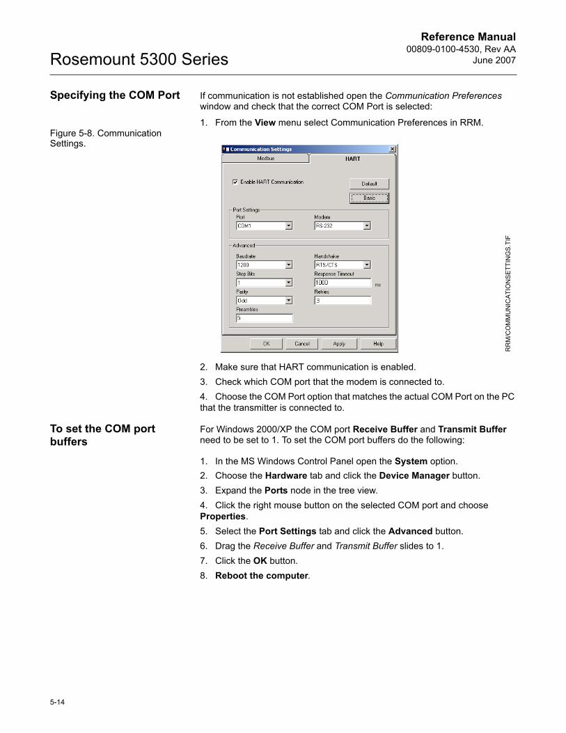
Reference Manual00809-0100-4530, Rev AA
June 2007Rosemount 5300 Series
Specifying the COM Port If communication is not established open the Communication Preferences window and check that the correct COM Port is selected:
1. From the View menu select Communication Preferences in RRM.Figure 5-8. Communication Settings.
2. Make sure that HART communication is enabled.3. Check which COM port that the modem is connected to.4. Choose the COM Port option that matches the actual COM Port on the PC that the transmitter is connected to.
To set the COM port buffers
For Windows 2000/XP the COM port Receive Buffer and Transmit Buffer need to be set to 1. To set the COM port buffers do the following:
1. In the MS Windows Control Panel open the System option.2. Choose the Hardware tab and click the Device Manager button.3. Expand the Ports node in the tree view.4. Click the right mouse button on the selected COM port and choose Properties.5. Select the Port Settings tab and click the Advanced button.6. Drag the Receive Buffer and Transmit Buffer slides to 1.7. Click the OK button.8. Reboot the computer.
RR
M/C
OM
MU
NIC
ATIO
NS
ETT
ING
S.T
IF
5-14
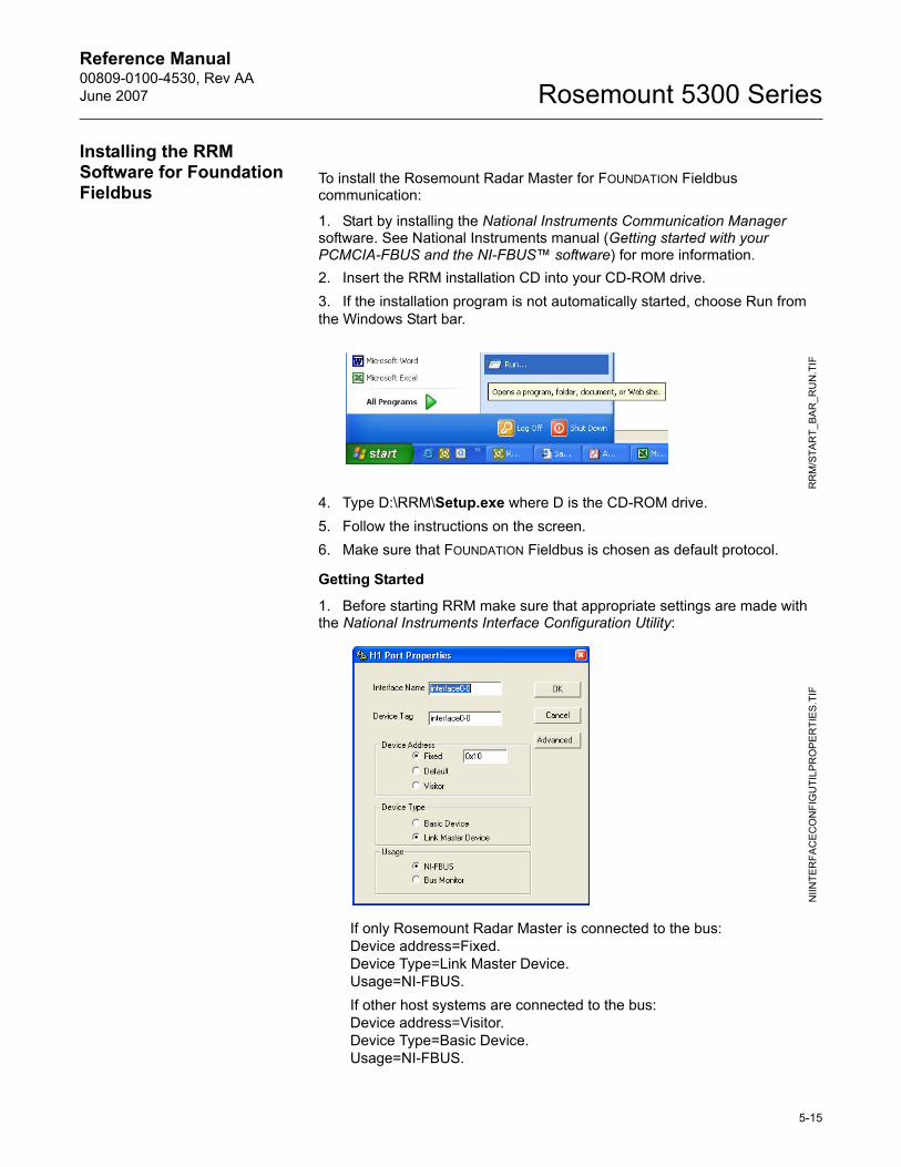
Reference Manual 00809-0100-4530, Rev AAJune 2007 Rosemount 5300 Series
Installing the RRM Software for Foundation Fieldbus
To install the Rosemount Radar Master for FOUNDATION Fieldbus communication:
1. Start by installing the National Instruments Communication Manager software. See National Instruments manual (Getting started with your PCMCIA-FBUS and the NI-FBUS� software) for more information.2. Insert the RRM installation CD into your CD-ROM drive.3. If the installation program is not automatically started, choose Run from the Windows Start bar.
4. Type D:\RRM\Setup.exe where D is the CD-ROM drive.5. Follow the instructions on the screen. 6. Make sure that FOUNDATION Fieldbus is chosen as default protocol.
Getting Started
1. Before starting RRM make sure that appropriate settings are made with the National Instruments Interface Configuration Utility:
If only Rosemount Radar Master is connected to the bus:Device address=Fixed.Device Type=Link Master Device.Usage=NI-FBUS.If other host systems are connected to the bus:Device address=Visitor.Device Type=Basic Device.Usage=NI-FBUS.
RR
M/S
TAR
T_BA
R_R
UN
.TIF
NIIN
TER
FAC
ECO
NFI
GU
TILP
RO
PE
RTI
ES
.TIF
5-15
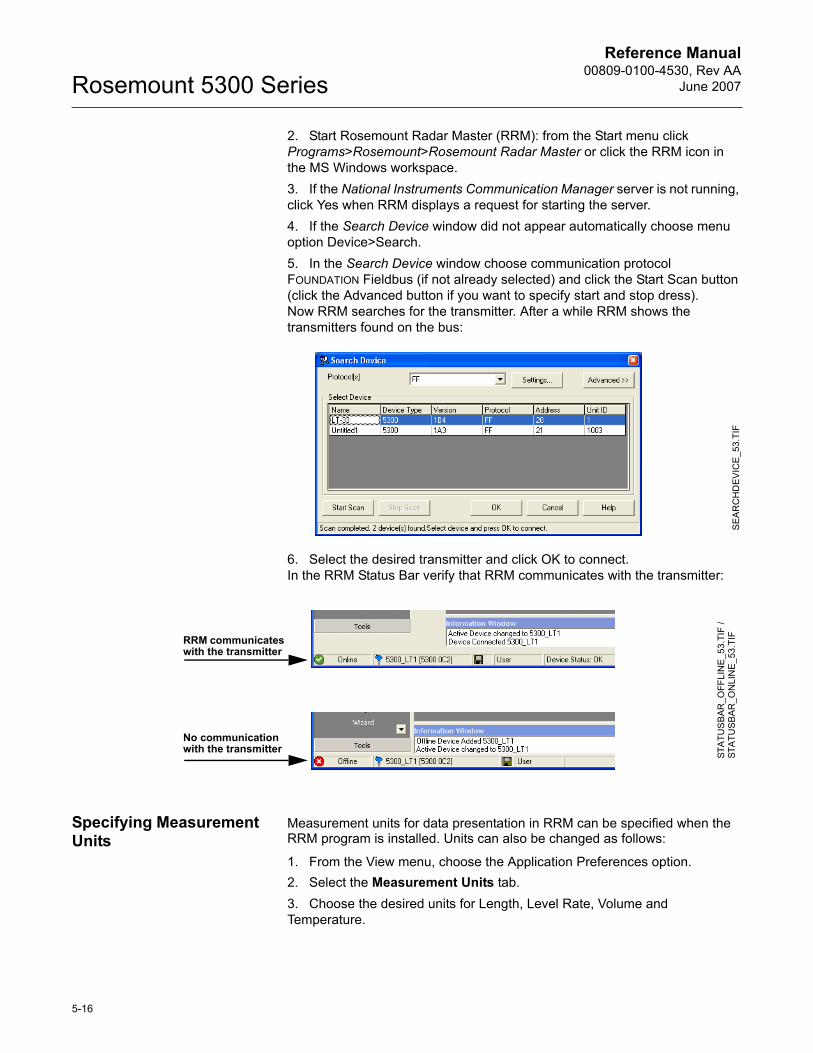
Reference Manual00809-0100-4530, Rev AA
June 2007Rosemount 5300 Series
2. Start Rosemount Radar Master (RRM): from the Start menu click Programs>Rosemount>Rosemount Radar Master or click the RRM icon in the MS Windows workspace. 3. If the National Instruments Communication Manager server is not running, click Yes when RRM displays a request for starting the server.4. If the Search Device window did not appear automatically choose menu option Device>Search.5. In the Search Device window choose communication protocol FOUNDATION Fieldbus (if not already selected) and click the Start Scan button (click the Advanced button if you want to specify start and stop dress).Now RRM searches for the transmitter. After a while RRM shows the transmitters found on the bus:
6. Select the desired transmitter and click OK to connect. In the RRM Status Bar verify that RRM communicates with the transmitter:
Specifying Measurement Units
Measurement units for data presentation in RRM can be specified when the RRM program is installed. Units can also be changed as follows:
1. From the View menu, choose the Application Preferences option. 2. Select the Measurement Units tab.3. Choose the desired units for Length, Level Rate, Volume and Temperature.
SEA
RC
HD
EV
ICE
_53.
TIF
STA
TUS
BAR
_OFF
LIN
E_5
3.TI
F /
STA
TUS
BAR
_ON
LIN
E_5
3.TI
FRRM communicates with the transmitter
No communication with the transmitter
5-16
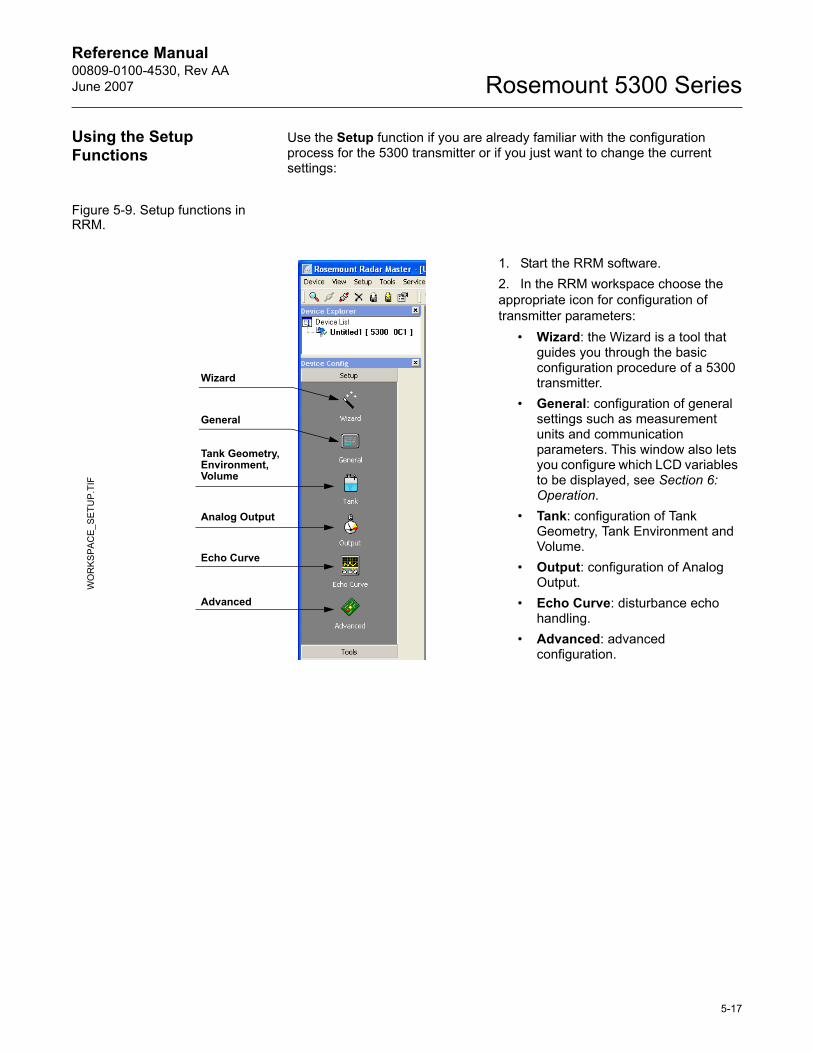
Reference Manual 00809-0100-4530, Rev AAJune 2007 Rosemount 5300 Series
Using the Setup Functions
Use the Setup function if you are already familiar with the configuration process for the 5300 transmitter or if you just want to change the current settings:
Figure 5-9. Setup functions in RRM.
1. Start the RRM software.2. In the RRM workspace choose the appropriate icon for configuration of transmitter parameters:
� Wizard: the Wizard is a tool that guides you through the basic configuration procedure of a 5300 transmitter.
� General: configuration of general settings such as measurement units and communication parameters. This window also lets you configure which LCD variables to be displayed, see Section 6: Operation.
� Tank: configuration of Tank Geometry, Tank Environment and Volume.
� Output: configuration of Analog Output.
� Echo Curve: disturbance echo handling.
� Advanced: advanced configuration.
WO
RK
SPA
CE
_SET
UP.
TIF
General
Tank Geometry, Environment, Volume
Analog Output
Echo Curve
Advanced
Wizard
5-17
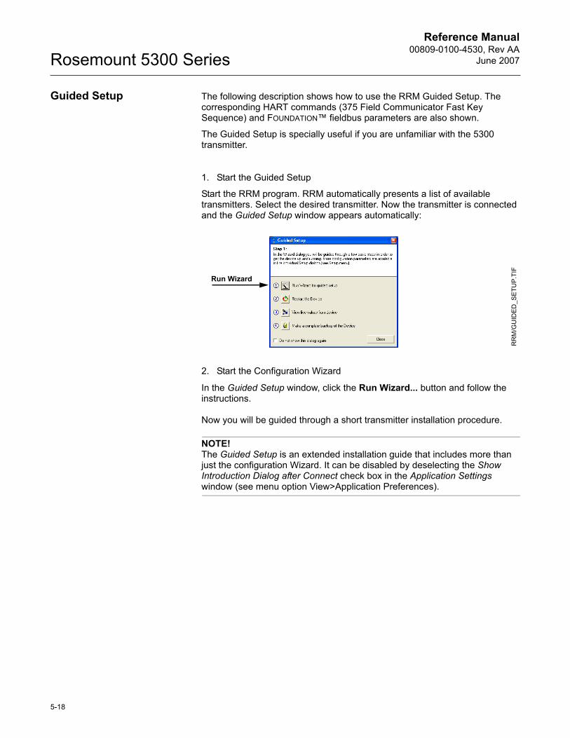
Reference Manual00809-0100-4530, Rev AA
June 2007Rosemount 5300 Series
Guided Setup The following description shows how to use the RRM Guided Setup. The corresponding HART commands (375 Field Communicator Fast Key Sequence) and FOUNDATION� fieldbus parameters are also shown.
The Guided Setup is specially useful if you are unfamiliar with the 5300 transmitter.
1. Start the Guided Setup
Start the RRM program. RRM automatically presents a list of available transmitters. Select the desired transmitter. Now the transmitter is connected and the Guided Setup window appears automatically:
2. Start the Configuration Wizard
In the Guided Setup window, click the Run Wizard... button and follow the instructions.
Now you will be guided through a short transmitter installation procedure.
NOTE!The Guided Setup is an extended installation guide that includes more than just the configuration Wizard. It can be disabled by deselecting the Show Introduction Dialog after Connect check box in the Application Settings window (see menu option View>Application Preferences).
Run Wizard
RR
M/G
UID
ED_S
ETU
P.T
IF
5-18
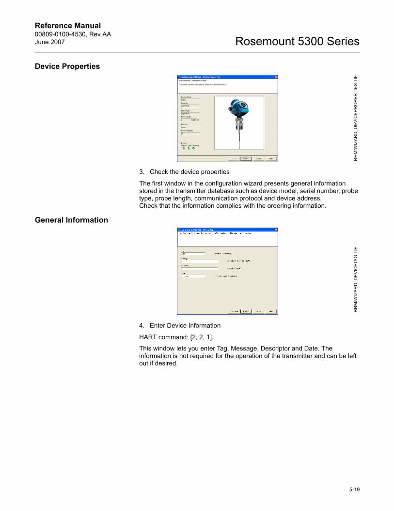
Reference Manual 00809-0100-4530, Rev AAJune 2007 Rosemount 5300 Series
Device Properties
3. Check the device properties
The first window in the configuration wizard presents general information stored in the transmitter database such as device model, serial number, probe type, probe length, communication protocol and device address.Check that the information complies with the ordering information.
General Information
4. Enter Device Information
HART command: [2, 2, 1].
This window lets you enter Tag, Message, Descriptor and Date. The information is not required for the operation of the transmitter and can be left out if desired.
RR
M/W
IZA
RD
_DE
VIC
EPR
OP
ER
TIE
S.T
IFR
RM
/WIZ
AR
D_D
EVI
CE
TAG
.TIF
5-19
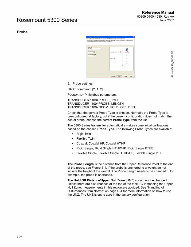
Reference Manual00809-0100-4530, Rev AA
June 2007Rosemount 5300 Series
Probe
5. Probe settings
HART command: [2, 1, 2].
FOUNDATION� fieldbus parameters:
TRANSDUCER 1100>PROBE_TYPETRANSDUCER 1100>PROBE_LENGTHTRANSDUCER 1100>GEOM_HOLD_OFF_DIST.
Check that the correct Probe Type is chosen. Normally the Probe Type is pre-configured at factory, but if the current configuration does not match the actual probe, choose the correct Probe Type from the list.
The 5300 Series transmitter automatically makes some initial calibrations based on the chosen Probe Type. The following Probe Types are available:
� Rigid Twin� Flexible Twin� Coaxial, Coaxial HP, Coaxial HTHP� Rigid Single, Rigid Single HTHP/HP, Rigid Single PTFE� Flexible Single, Flexible Single HTHP/HP, Flexible Single PTFE
The Probe Length is the distance from the Upper Reference Point to the end of the probe, see Figure 5-1. If the probe is anchored to a weight do not include the height of the weight. The Probe Length needs to be changed if, for example, the probe is shortened.
The Hold Off Distance/Upper Null Zone (UNZ) should not be changed unless there are disturbances at the top of the tank. By increasing the Upper Null Zone, measurements in this region are avoided. See �Handling of Disturbances from Nozzle� on page C-4 for more information on how to use the UNZ. The UNZ is set to zero in the factory configuration.
RR
M/W
IZA
RD
_PR
OB
E.TI
F
5-20
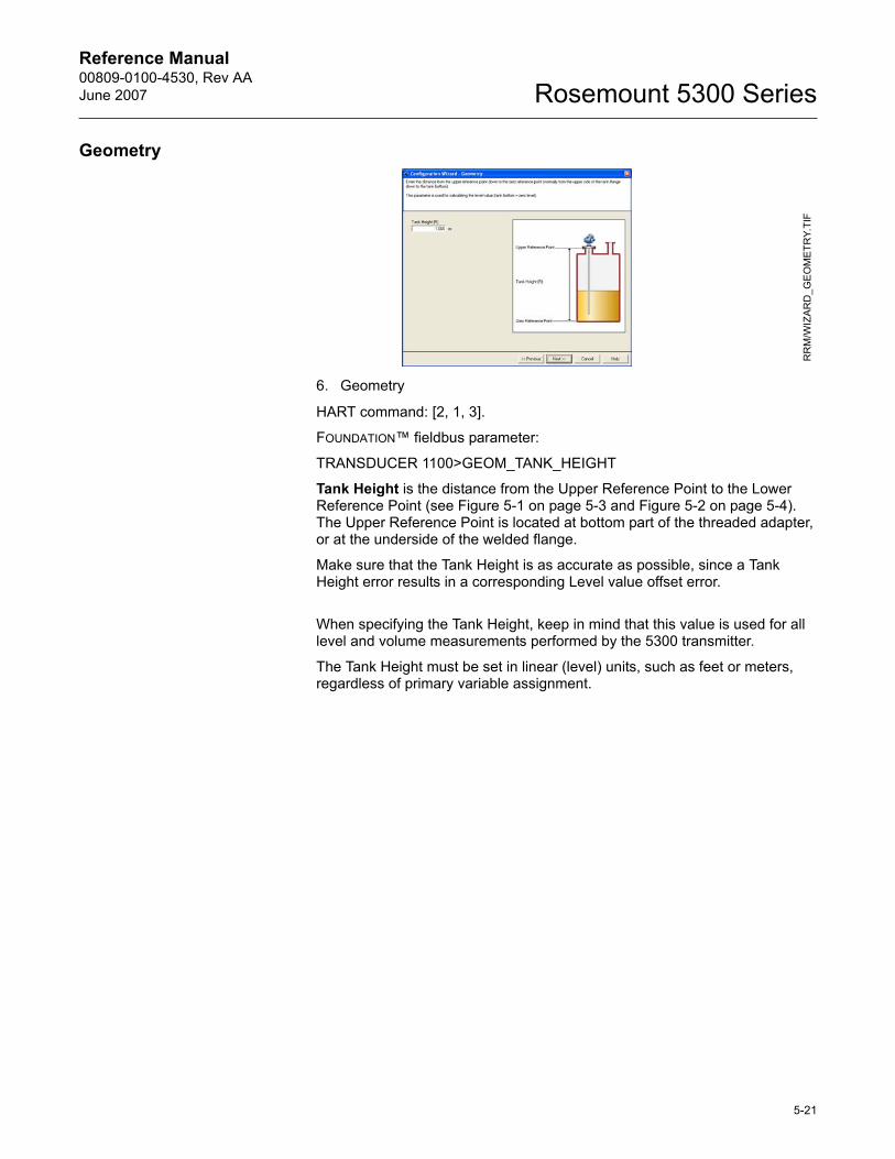
Reference Manual 00809-0100-4530, Rev AAJune 2007 Rosemount 5300 Series
Geometry
6. Geometry
HART command: [2, 1, 3].
FOUNDATION� fieldbus parameter:
TRANSDUCER 1100>GEOM_TANK_HEIGHT
Tank Height is the distance from the Upper Reference Point to the Lower Reference Point (see Figure 5-1 on page 5-3 and Figure 5-2 on page 5-4). The Upper Reference Point is located at bottom part of the threaded adapter, or at the underside of the welded flange.
Make sure that the Tank Height is as accurate as possible, since a Tank Height error results in a corresponding Level value offset error.
When specifying the Tank Height, keep in mind that this value is used for all level and volume measurements performed by the 5300 transmitter.
The Tank Height must be set in linear (level) units, such as feet or meters, regardless of primary variable assignment.
RR
M/W
IZAR
D_G
EO
ME
TRY.
TIF
5-21
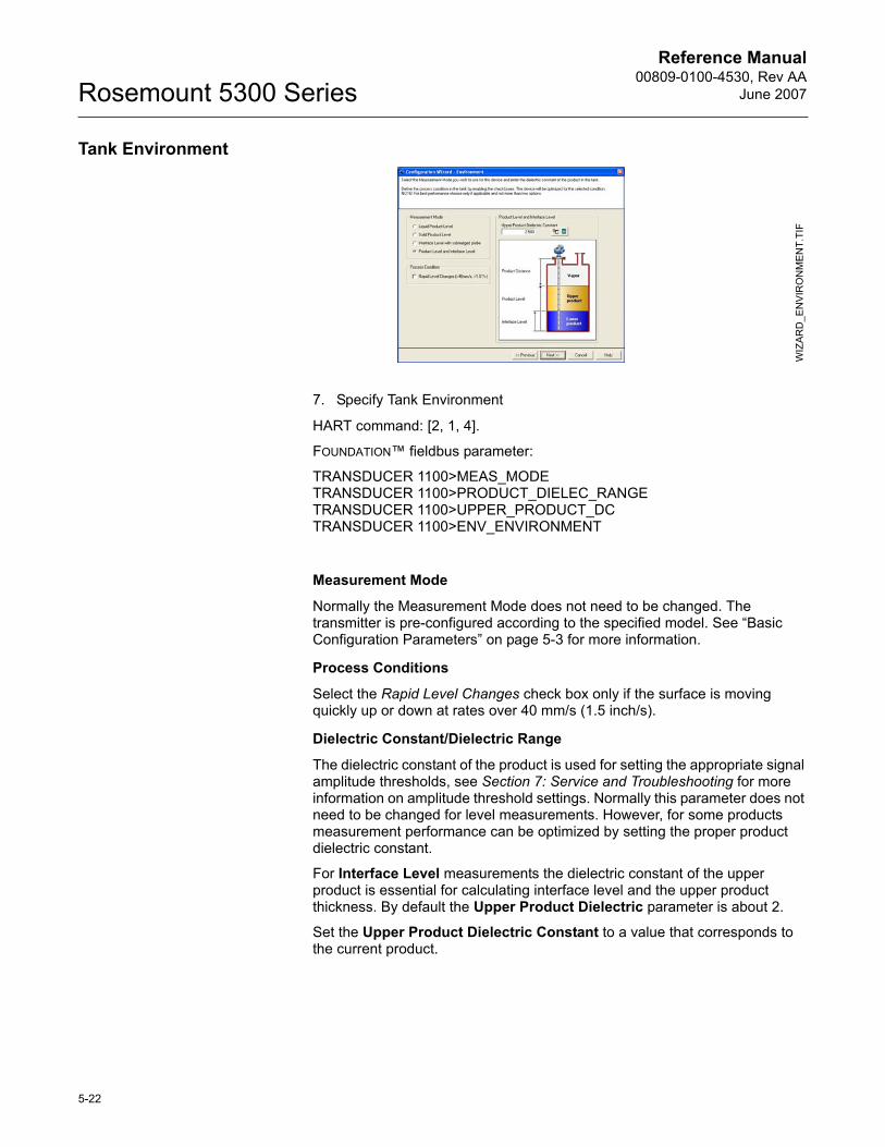
Reference Manual00809-0100-4530, Rev AA
June 2007Rosemount 5300 Series
Tank Environment
7. Specify Tank Environment
HART command: [2, 1, 4].
FOUNDATION� fieldbus parameter:
TRANSDUCER 1100>MEAS_MODETRANSDUCER 1100>PRODUCT_DIELEC_RANGETRANSDUCER 1100>UPPER_PRODUCT_DCTRANSDUCER 1100>ENV_ENVIRONMENT
Measurement Mode
Normally the Measurement Mode does not need to be changed. The transmitter is pre-configured according to the specified model. See �Basic Configuration Parameters� on page 5-3 for more information.
Process Conditions
Select the Rapid Level Changes check box only if the surface is moving quickly up or down at rates over 40 mm/s (1.5 inch/s).
Dielectric Constant/Dielectric Range
The dielectric constant of the product is used for setting the appropriate signal amplitude thresholds, see Section 7: Service and Troubleshooting for more information on amplitude threshold settings. Normally this parameter does not need to be changed for level measurements. However, for some products measurement performance can be optimized by setting the proper product dielectric constant.
For Interface Level measurements the dielectric constant of the upper product is essential for calculating interface level and the upper product thickness. By default the Upper Product Dielectric parameter is about 2.
Set the Upper Product Dielectric Constant to a value that corresponds to the current product.
WIZ
ARD
_EN
VIR
ON
ME
NT.
TIF
5-22
Reference Manual 00809-0100-4530, Rev AAJune 2007 Rosemount 5300 Series
Rosemount Radar Master (RRM) includes tools to estimate the dielectric constant of the current product:
� The Dielectric Chart lists the dielectric constant of a large number of products. The Dielectric Chart can be opened with one of the following methods:- Choose the View>Dielectric Constant Chart menu option- Click the Dielectric Chart button in the Configuration Wizard - Environment window - Choose the Setup>Tank menu option and click the Dielectric Chart button in the Tank/Environment window
� The Dielectric Calculator lets you calculate the dielectric constant of the Upper Product based on the following input:- actual upper product thickness,- the dielectric constant value stored in the transmitter, and- the upper product thickness presented by the transmitter.
The Dielectric Calculator is available via the Dielectric Calculator button in the Configuration Wizard - Environment window or the Tank/Environment window.
5-23
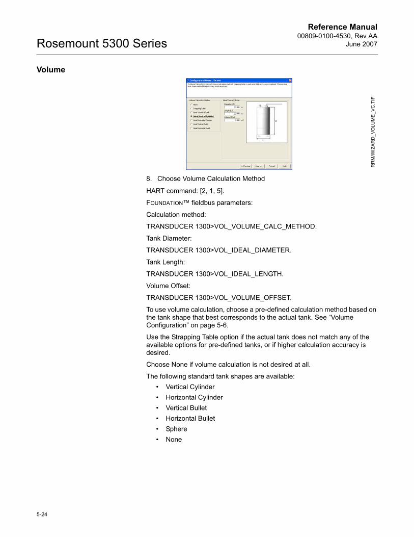
Reference Manual00809-0100-4530, Rev AA
June 2007Rosemount 5300 Series
Volume
8. Choose Volume Calculation Method
HART command: [2, 1, 5].
FOUNDATION� fieldbus parameters:
Calculation method:
TRANSDUCER 1300>VOL_VOLUME_CALC_METHOD.
Tank Diameter:
TRANSDUCER 1300>VOL_IDEAL_DIAMETER.
Tank Length:
TRANSDUCER 1300>VOL_IDEAL_LENGTH.
Volume Offset:
TRANSDUCER 1300>VOL_VOLUME_OFFSET.
To use volume calculation, choose a pre-defined calculation method based on the tank shape that best corresponds to the actual tank. See �Volume Configuration� on page 5-6.
Use the Strapping Table option if the actual tank does not match any of the available options for pre-defined tanks, or if higher calculation accuracy is desired.
Choose None if volume calculation is not desired at all.
The following standard tank shapes are available:� Vertical Cylinder� Horizontal Cylinder� Vertical Bullet� Horizontal Bullet� Sphere� None
RR
M/W
IZAR
D_V
OLU
ME
_VC
.TIF
5-24

Reference Manual 00809-0100-4530, Rev AAJune 2007 Rosemount 5300 Series
The following parameters must be entered for a standard tank shape:� Tank diameter.� Tank height/length (not for spherical tanks).� Volume Offset: use this parameter if you do not want zero volume and
zero level to match (for example if you want to include a volume below the zero level).
5-25
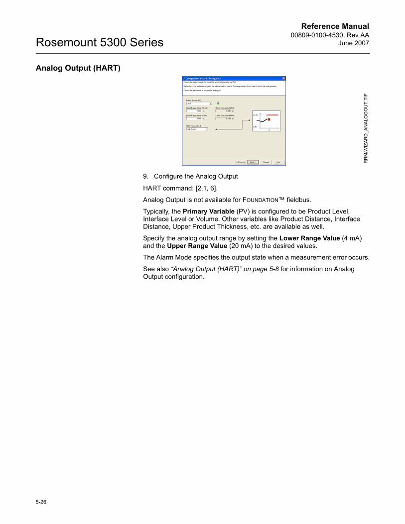
Reference Manual00809-0100-4530, Rev AA
June 2007Rosemount 5300 Series
Analog Output (HART)
9. Configure the Analog Output
HART command: [2,1, 6].
Analog Output is not available for FOUNDATION� fieldbus.
Typically, the Primary Variable (PV) is configured to be Product Level, Interface Level or Volume. Other variables like Product Distance, Interface Distance, Upper Product Thickness, etc. are available as well.
Specify the analog output range by setting the Lower Range Value (4 mA) and the Upper Range Value (20 mA) to the desired values.
The Alarm Mode specifies the output state when a measurement error occurs.
See also �Analog Output (HART)� on page 5-8 for information on Analog Output configuration.
RR
M/W
IZA
RD
_AN
ALO
GO
UT.
TIF
5-26
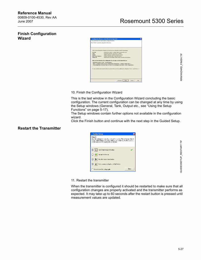
Reference Manual 00809-0100-4530, Rev AAJune 2007 Rosemount 5300 Series
Finish Configuration Wizard
10. Finish the Configuration Wizard
This is the last window in the Configuration Wizard concluding the basic configuration. The current configuration can be changed at any time by using the Setup windows (General, Tank, Output etc., see �Using the Setup Functions� on page 5-17). The Setup windows contain further options not available in the configuration wizard.Click the Finish button and continue with the next step in the Guided Setup.
Restart the Transmitter
11. Restart the transmitter
When the transmitter is configured it should be restarted to make sure that all configuration changes are properly activated and the transmitter performs as expected. It may take up to 60 seconds after the restart button is pressed until measurement values are updated.
RR
M/W
IZAR
D_F
INIS
H.T
IFG
UID
ED
SETU
P_R
EST
ART.
TIF
5-27
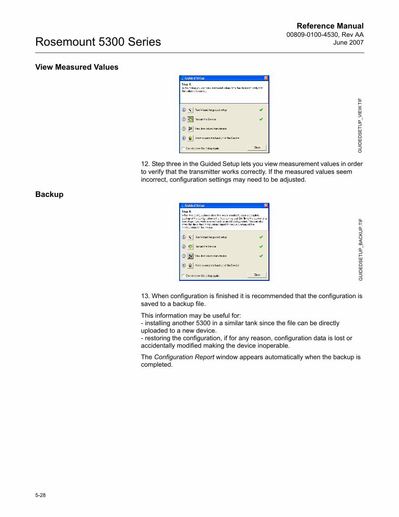
Reference Manual00809-0100-4530, Rev AA
June 2007Rosemount 5300 Series
View Measured Values
12. Step three in the Guided Setup lets you view measurement values in order to verify that the transmitter works correctly. If the measured values seem incorrect, configuration settings may need to be adjusted.
Backup
13. When configuration is finished it is recommended that the configuration is saved to a backup file.
This information may be useful for:- installing another 5300 in a similar tank since the file can be directly uploaded to a new device.- restoring the configuration, if for any reason, configuration data is lost or accidentally modified making the device inoperable.
The Configuration Report window appears automatically when the backup is completed.
GU
IDE
DSE
TUP
_VIE
W.T
IFG
UID
ED
SE
TUP_
BA
CKU
P.TI
F
5-28
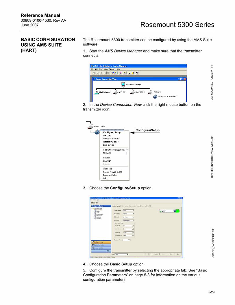
Reference Manual 00809-0100-4530, Rev AAJune 2007 Rosemount 5300 Series
BASIC CONFIGURATION USING AMS SUITE (HART)
The Rosemount 5300 transmitter can be configured by using the AMS Suite software.
1. Start the AMS Device Manager and make sure that the transmitter connects.
2. In the Device Connection View click the right mouse button on the transmitter icon.
3. Choose the Configure/Setup option:
4. Choose the Basic Setup option.5. Configure the transmitter by selecting the appropriate tab. See �Basic Configuration Parameters� on page 5-3 for information on the various configuration parameters.
DE
VIC
EC
ON
NE
CTI
ON
VIE
W.T
IFIF
DE
VIC
EC
ON
NE
CTI
ON
VIEW
_ME
NU
.TIF
Configure/Setup
CO
NFI
G_B
AS
ICS
ETU
P.T
IF
5-29
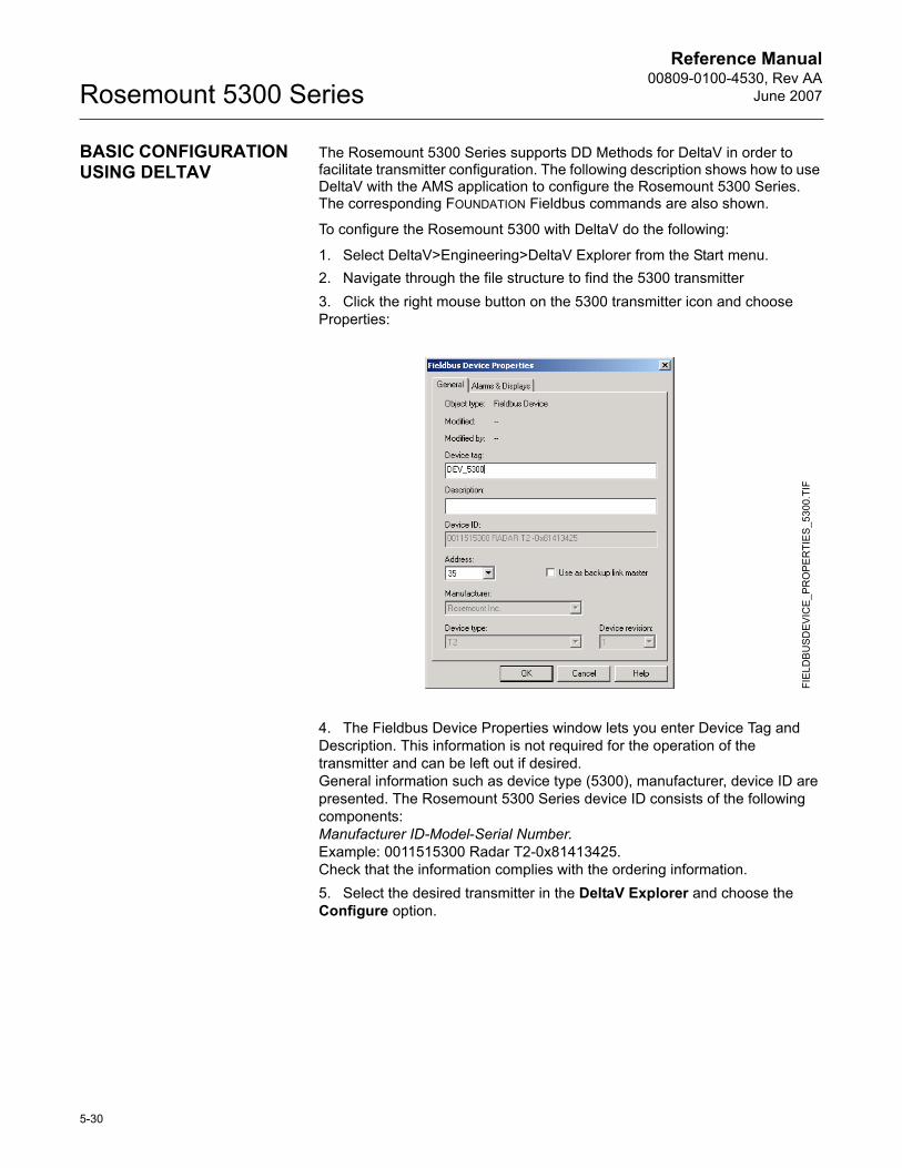
Reference Manual00809-0100-4530, Rev AA
June 2007Rosemount 5300 Series
BASIC CONFIGURATION USING DELTAV
The Rosemount 5300 Series supports DD Methods for DeltaV in order to facilitate transmitter configuration. The following description shows how to use DeltaV with the AMS application to configure the Rosemount 5300 Series. The corresponding FOUNDATION Fieldbus commands are also shown.
To configure the Rosemount 5300 with DeltaV do the following:
1. Select DeltaV>Engineering>DeltaV Explorer from the Start menu.2. Navigate through the file structure to find the 5300 transmitter3. Click the right mouse button on the 5300 transmitter icon and choose Properties:
4. The Fieldbus Device Properties window lets you enter Device Tag and Description. This information is not required for the operation of the transmitter and can be left out if desired.General information such as device type (5300), manufacturer, device ID are presented. The Rosemount 5300 Series device ID consists of the following components:Manufacturer ID-Model-Serial Number. Example: 0011515300 Radar T2-0x81413425.Check that the information complies with the ordering information.5. Select the desired transmitter in the DeltaV Explorer and choose the Configure option.
FIE
LDB
USD
EVIC
E_P
RO
PE
RTI
ES
_530
0.TI
F
5-30
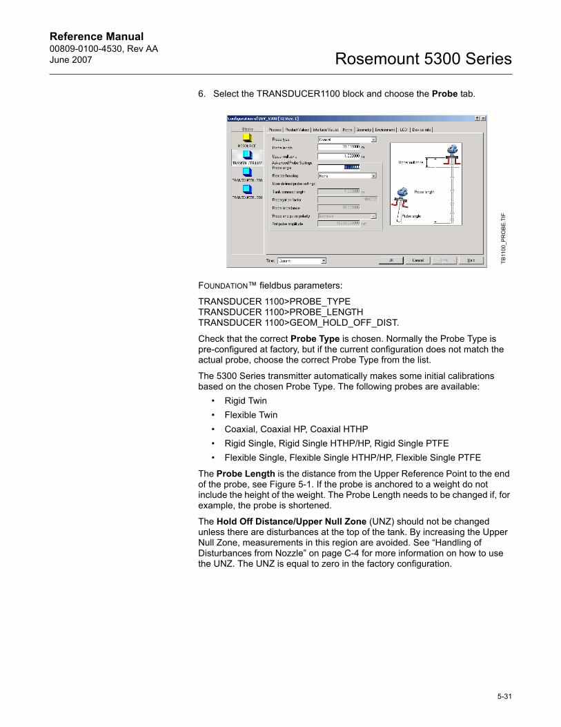
Reference Manual 00809-0100-4530, Rev AAJune 2007 Rosemount 5300 Series
6. Select the TRANSDUCER1100 block and choose the Probe tab.
FOUNDATION� fieldbus parameters:
TRANSDUCER 1100>PROBE_TYPETRANSDUCER 1100>PROBE_LENGTHTRANSDUCER 1100>GEOM_HOLD_OFF_DIST.
Check that the correct Probe Type is chosen. Normally the Probe Type is pre-configured at factory, but if the current configuration does not match the actual probe, choose the correct Probe Type from the list.
The 5300 Series transmitter automatically makes some initial calibrations based on the chosen Probe Type. The following probes are available:
� Rigid Twin� Flexible Twin� Coaxial, Coaxial HP, Coaxial HTHP� Rigid Single, Rigid Single HTHP/HP, Rigid Single PTFE� Flexible Single, Flexible Single HTHP/HP, Flexible Single PTFE
The Probe Length is the distance from the Upper Reference Point to the end of the probe, see Figure 5-1. If the probe is anchored to a weight do not include the height of the weight. The Probe Length needs to be changed if, for example, the probe is shortened.
The Hold Off Distance/Upper Null Zone (UNZ) should not be changed unless there are disturbances at the top of the tank. By increasing the Upper Null Zone, measurements in this region are avoided. See �Handling of Disturbances from Nozzle� on page C-4 for more information on how to use the UNZ. The UNZ is equal to zero in the factory configuration.
TB11
00_P
RO
BE.
TIF
5-31
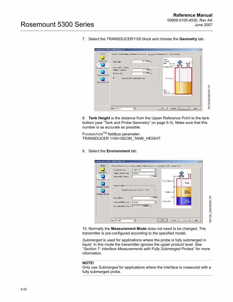
Reference Manual00809-0100-4530, Rev AA
June 2007Rosemount 5300 Series
7. Select the TRANSDUCER1100 block and choose the Geometry tab.
8. Tank Height is the distance from the Upper Reference Point to the tank bottom (see �Tank and Probe Geometry� on page 5-3). Make sure that this number is as accurate as possible.
FOUNDATIONTM fieldbus parameter: TRANSDUCER 1100>GEOM_TANK_HEIGHT.
9. Select the Environment tab.
10. Normally the Measurement Mode does not need to be changed. The transmitter is pre-configured according to the specified model.
Submerged is used for applications where the probe is fully submerged in liquid. In this mode the transmitter ignores the upper product level. See �Section 7: Interface Measurements with Fully Submerged Probes� for more information.
NOTE!Only use Submerged for applications where the interface is measured with a fully submerged probe.
TB11
00G
EOM
ETR
Y.TI
FTB
1100
_EN
VIR
ON
.TIF
5-32
Reference Manual 00809-0100-4530, Rev AAJune 2007 Rosemount 5300 Series
FOUNDATION� fieldbus parameter:
TRANSDUCER 1100>MEAS_MODE
Dielectric Constant/Dielectric Range
The dielectric constant of the product is used for setting the appropriate signal amplitude thresholds, see Section 7: Service and Troubleshooting for more information on amplitude threshold settings. Normally this parameter does not need to be changed for level measurements. However, for some products measurement performance can be optimized by setting the proper product dielectric constant.
For Interface Level measurements the dielectric constant of the upper product is essential for calculating interface level and the upper product thickness. By default the Upper Product Dielectric parameter is about 2.
Set the Upper Product Dielectric Constant to a value that corresponds to the current product.
FOUNDATION� fieldbus parameters:TRANSDUCER 1100>PRODUCT_DIELEC_RANGETRANSDUCER 1100>UPPER_PRODUCT_DC
Process Conditions
Select the Rapid Level Changes check box only if the surface is moving quickly up or down at rates over 40 mm/s (1.5 inch/s).
FOUNDATION� fieldbus parameter:
TRANSDUCER 1100>ENV_ENVIRONMENT
5-33
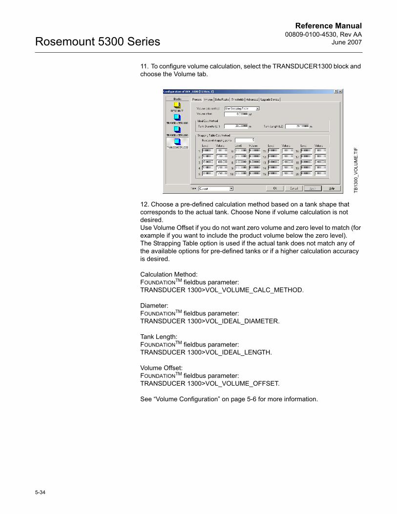
Reference Manual00809-0100-4530, Rev AA
June 2007Rosemount 5300 Series
11. To configure volume calculation, select the TRANSDUCER1300 block and choose the Volume tab.
12. Choose a pre-defined calculation method based on a tank shape that corresponds to the actual tank. Choose None if volume calculation is not desired.Use Volume Offset if you do not want zero volume and zero level to match (for example if you want to include the product volume below the zero level).The Strapping Table option is used if the actual tank does not match any of the available options for pre-defined tanks or if a higher calculation accuracy is desired.
Calculation Method:FOUNDATIONTM fieldbus parameter: TRANSDUCER 1300>VOL_VOLUME_CALC_METHOD.
Diameter:FOUNDATIONTM fieldbus parameter: TRANSDUCER 1300>VOL_IDEAL_DIAMETER.
Tank Length:FOUNDATIONTM fieldbus parameter: TRANSDUCER 1300>VOL_IDEAL_LENGTH.
Volume Offset:FOUNDATIONTM fieldbus parameter: TRANSDUCER 1300>VOL_VOLUME_OFFSET.
See �Volume Configuration� on page 5-6 for more information.
TB13
00_V
OLU
ME
.TIF
5-34
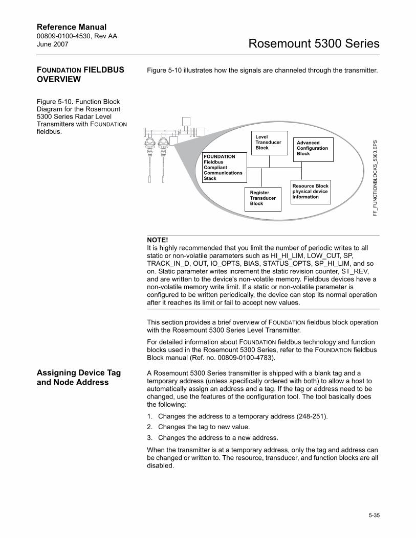
Reference Manual 00809-0100-4530, Rev AAJune 2007 Rosemount 5300 Series
FOUNDATION FIELDBUS OVERVIEW
Figure 5-10 illustrates how the signals are channeled through the transmitter.
Figure 5-10. Function Block Diagram for the Rosemount 5300 Series Radar Level Transmitters with FOUNDATION fieldbus.
NOTE!It is highly recommended that you limit the number of periodic writes to all static or non-volatile parameters such as HI_HI_LIM, LOW_CUT, SP, TRACK_IN_D, OUT, IO_OPTS, BIAS, STATUS_OPTS, SP_HI_LIM, and so on. Static parameter writes increment the static revision counter, ST_REV, and are written to the device's non-volatile memory. Fieldbus devices have a non-volatile memory write limit. If a static or non-volatile parameter is configured to be written periodically, the device can stop its normal operation after it reaches its limit or fail to accept new values.
This section provides a brief overview of FOUNDATION fieldbus block operation with the Rosemount 5300 Series Level Transmitter.
For detailed information about FOUNDATION fieldbus technology and function blocks used in the Rosemount 5300 Series, refer to the FOUNDATION fieldbus Block manual (Ref. no. 00809-0100-4783).
Assigning Device Tag and Node Address
A Rosemount 5300 Series transmitter is shipped with a blank tag and a temporary address (unless specifically ordered with both) to allow a host to automatically assign an address and a tag. If the tag or address need to be changed, use the features of the configuration tool. The tool basically does the following:
1. Changes the address to a temporary address (248-251).2. Changes the tag to new value.3. Changes the address to a new address.
When the transmitter is at a temporary address, only the tag and address can be changed or written to. The resource, transducer, and function blocks are all disabled.
FOUNDATION FieldbusCompliantCommunicationsStack
Level Transducer Block
Register Transducer Block
Resource Block physical device information
FF_F
UN
CTI
ON
BLO
CK
S_53
00.E
PSAdvanced Configuration Block
5-35
Reference Manual00809-0100-4530, Rev AA
June 2007Rosemount 5300 Series
FOUNDATION Fieldbus Block Operation
Function blocks within the fieldbus device perform the various functions required for process control. Function blocks perform process control functions, such as analog input (AI) functions, as well as proportional-integral derivative (PID) functions. The standard function blocks provide a common structure for defining function block inputs, outputs, control parameters, events, alarms, and modes, and combining them into a process that can be implemented within a single device or over the fieldbus network. This simplifies the identification of characteristics that are common to function blocks.
In addition to function blocks, fieldbus devices contain two other block types to support the function blocks. These are the Resource block and the Transducer block.
Resource blocks contain the hardware specific characteristics associated with a device; they have no input or output parameters. The algorithm within a resource block monitors and controls the general operation of the physical device hardware. There is only one resource block defined for a device.
Transducer blocks connect function blocks to local input/output functions. They read sensor hardware and write to effector (actuator) hardware.
Level Transducer Block
The Level Transducer block contains transmitter information including diagnostics and the ability to configure, set to factory defaults and restarting the transmitter.
Register Transducer Block
The Register Transducer Block allows a service engineer to access all database registers in the device.
Advanced Configuration Transducer Block
The Advanced Configuration Transducer Block contains functions such as amplitude threshold settings for filtering of disturbing echoes and noise, simulation of measurement values and strapping table for volume measurements.
Resource Block
The Resource block contains diagnostic, hardware, electronics, and mode handling information. There are no linkable inputs or outputs to the Resource Block.
5-36
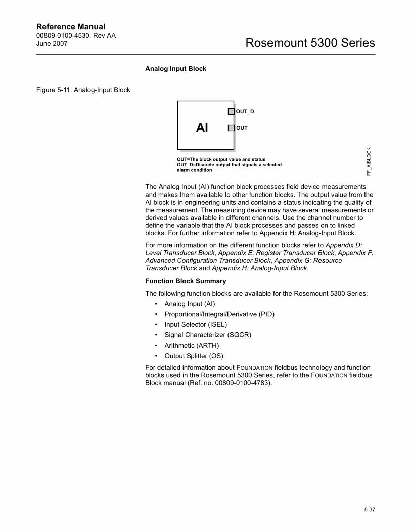
Reference Manual 00809-0100-4530, Rev AAJune 2007 Rosemount 5300 Series
Analog Input Block
Figure 5-11. Analog-Input Block
The Analog Input (AI) function block processes field device measurements and makes them available to other function blocks. The output value from the AI block is in engineering units and contains a status indicating the quality of the measurement. The measuring device may have several measurements or derived values available in different channels. Use the channel number to define the variable that the AI block processes and passes on to linked blocks. For further information refer to Appendix H: Analog-Input Block.
For more information on the different function blocks refer to Appendix D: Level Transducer Block, Appendix E: Register Transducer Block, Appendix F: Advanced Configuration Transducer Block, Appendix G: Resource Transducer Block and Appendix H: Analog-Input Block.
Function Block Summary
The following function blocks are available for the Rosemount 5300 Series:� Analog Input (AI)� Proportional/Integral/Derivative (PID)� Input Selector (ISEL)� Signal Characterizer (SGCR)� Arithmetic (ARTH)� Output Splitter (OS)
For detailed information about FOUNDATION fieldbus technology and function blocks used in the Rosemount 5300 Series, refer to the FOUNDATION fieldbus Block manual (Ref. no. 00809-0100-4783).
OUT=The block output value and statusOUT_D=Discrete output that signals a selected alarm condition
OUT_D
OUT
FF_A
IBLO
CK
AI
5-37
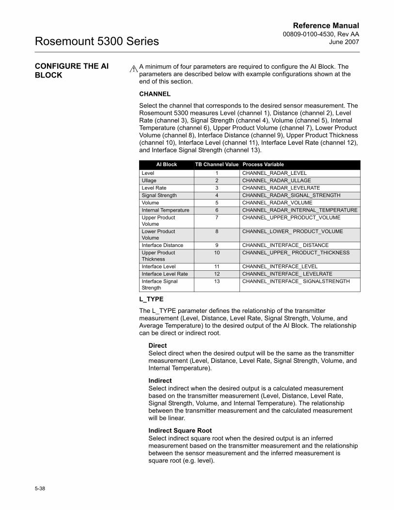
Reference Manual00809-0100-4530, Rev AA
June 2007Rosemount 5300 Series
CONFIGURE THE AI BLOCK
A minimum of four parameters are required to configure the AI Block. The parameters are described below with example configurations shown at the end of this section.
CHANNEL
Select the channel that corresponds to the desired sensor measurement. The Rosemount 5300 measures Level (channel 1), Distance (channel 2), Level Rate (channel 3), Signal Strength (channel 4), Volume (channel 5), Internal Temperature (channel 6), Upper Product Volume (channel 7), Lower Product Volume (channel 8), Interface Distance (channel 9), Upper Product Thickness (channel 10), Interface Level (channel 11), Interface Level Rate (channel 12), and Interface Signal Strength (channel 13).
L_TYPE
The L_TYPE parameter defines the relationship of the transmitter measurement (Level, Distance, Level Rate, Signal Strength, Volume, and Average Temperature) to the desired output of the AI Block. The relationship can be direct or indirect root.
DirectSelect direct when the desired output will be the same as the transmitter measurement (Level, Distance, Level Rate, Signal Strength, Volume, and Internal Temperature).
IndirectSelect indirect when the desired output is a calculated measurement based on the transmitter measurement (Level, Distance, Level Rate, Signal Strength, Volume, and Internal Temperature). The relationship between the transmitter measurement and the calculated measurement will be linear.
Indirect Square RootSelect indirect square root when the desired output is an inferred measurement based on the transmitter measurement and the relationship between the sensor measurement and the inferred measurement is square root (e.g. level).
AI Block TB Channel Value Process VariableLevel 1 CHANNEL_RADAR_LEVELUllage 2 CHANNEL_RADAR_ULLAGELevel Rate 3 CHANNEL_RADAR_LEVELRATESignal Strength 4 CHANNEL_RADAR_SIGNAL_STRENGTHVolume 5 CHANNEL_RADAR_VOLUMEInternal Temperature 6 CHANNEL_RADAR_INTERNAL_TEMPERATUREUpper Product Volume
7 CHANNEL_UPPER_PRODUCT_VOLUME
Lower Product Volume
8 CHANNEL_LOWER_ PRODUCT_VOLUME
Interface Distance 9 CHANNEL_INTERFACE_ DISTANCEUpper Product Thickness
10 CHANNEL_UPPER_ PRODUCT_THICKNESS
Interface Level 11 CHANNEL_INTERFACE_LEVELInterface Level Rate 12 CHANNEL_INTERFACE_ LEVELRATEInterface Signal Strength
13 CHANNEL_INTERFACE_ SIGNALSTRENGTH
5-38
Reference Manual 00809-0100-4530, Rev AAJune 2007 Rosemount 5300 Series
XD_SCALE and OUT_SCALE
The XD_SCALE and OUT_SCALE each include three parameters: 0%, 100%, and, engineering units. Set these based on the L_TYPE:
L_TYPE is DirectWhen the desired output is the measured variable, set the XD_SCALE to represent the operating range of the process. Set OUT_SCALE to match XD_SCALE.
L_TYPE is Indirect When an inferred measurement is made based on the sensor measurement, set the XD_SCALE to represent the operating range that the sensor will see in the process. Determine the inferred measurement values that correspond to the XD_SCALE 0 and 100% points and set these for the OUT_SCALE.
L_TYPE is Indirect Square RootWhen an inferred measurement is made based on the transmitter measurement and the relationship between the inferred measurement and sensor measurement is square root, set the XD_SCALE to represent the operating range that the sensor will see in the process. Determine the inferred measurement values that correspond to the XD_SCALE 0 and 100% points and set these for the OUT_SCALE.
5-39
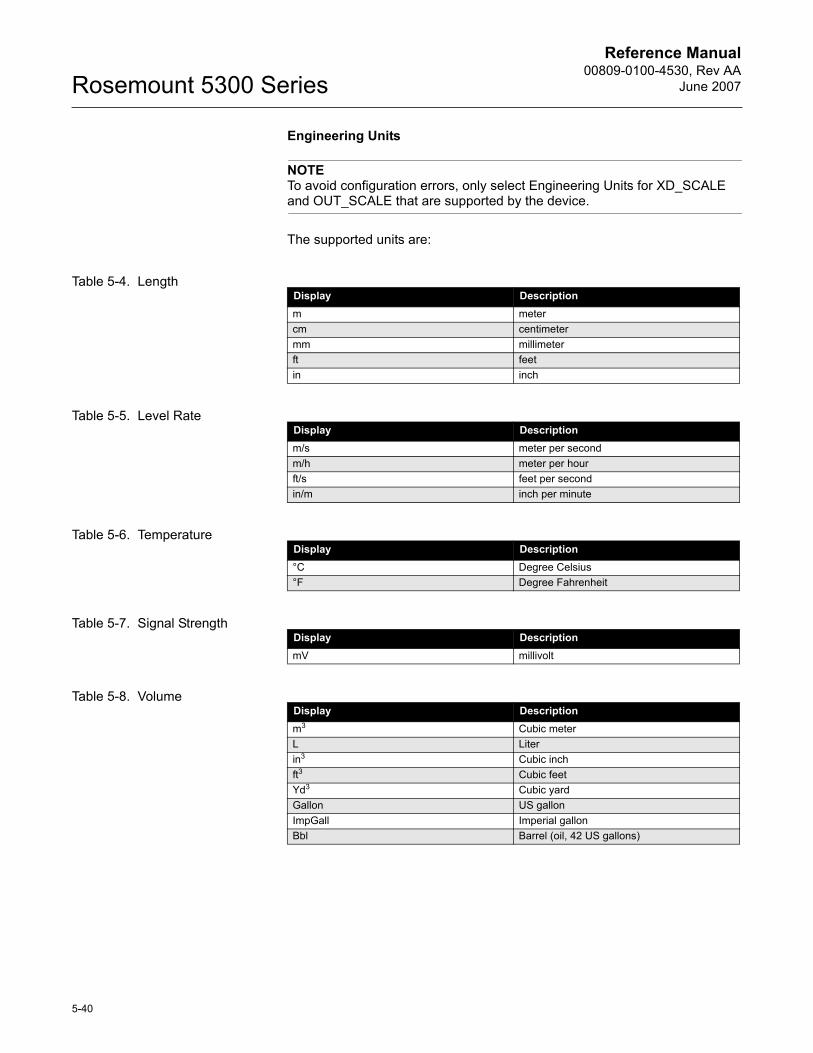
Reference Manual00809-0100-4530, Rev AA
June 2007Rosemount 5300 Series
Engineering Units
NOTETo avoid configuration errors, only select Engineering Units for XD_SCALE and OUT_SCALE that are supported by the device.
The supported units are:
Table 5-4. Length
Table 5-5. Level Rate
Table 5-6. Temperature
Table 5-7. Signal Strength
Table 5-8. Volume
Display Descriptionm metercm centimetermm millimeterft feetin inch
Display Descriptionm/s meter per secondm/h meter per hourft/s feet per secondin/m inch per minute
Display Description°C Degree Celsius°F Degree Fahrenheit
Display DescriptionmV millivolt
Display Descriptionm3 Cubic meterL Literin3 Cubic inchft3 Cubic feetYd3 Cubic yardGallon US gallonImpGall Imperial gallonBbl Barrel (oil, 42 US gallons)
5-40
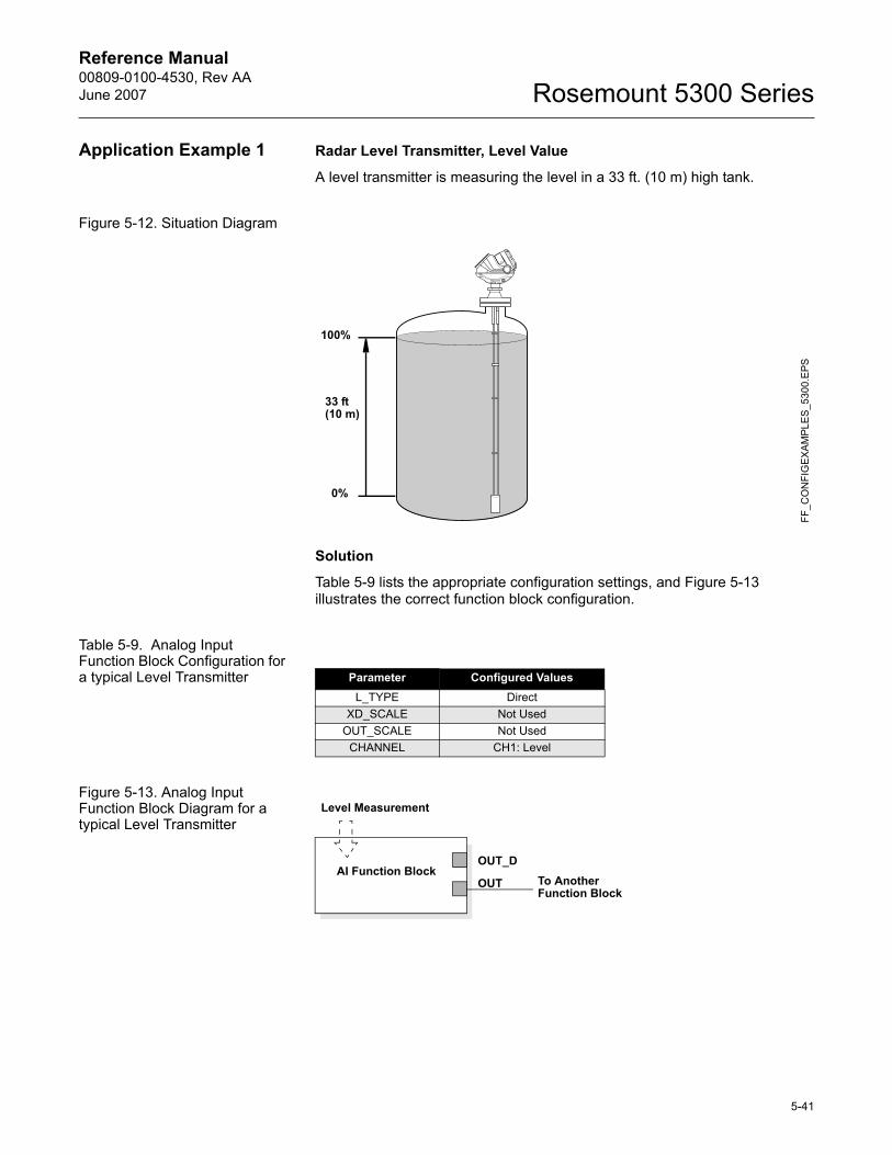
Reference Manual 00809-0100-4530, Rev AAJune 2007 Rosemount 5300 Series
Application Example 1 Radar Level Transmitter, Level Value
A level transmitter is measuring the level in a 33 ft. (10 m) high tank.
Figure 5-12. Situation Diagram
Solution
Table 5-9 lists the appropriate configuration settings, and Figure 5-13 illustrates the correct function block configuration.
Table 5-9. Analog Input Function Block Configuration for a typical Level Transmitter
Figure 5-13. Analog Input Function Block Diagram for a typical Level Transmitter
33 ft(10 m)
100%
0%
FF_C
ON
FIG
EXA
MPL
ES
_530
0.EP
S
Parameter Configured ValuesL_TYPE Direct
XD_SCALE Not UsedOUT_SCALE Not Used
CHANNEL CH1: Level
Level Measurement
To Another Function Block
OUT_D
OUTAI Function Block
5-41
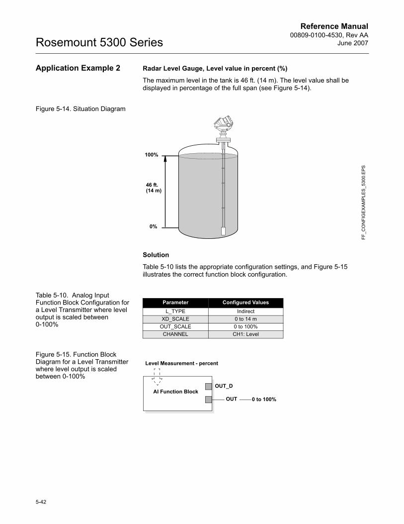
Reference Manual00809-0100-4530, Rev AA
June 2007Rosemount 5300 Series
Application Example 2 Radar Level Gauge, Level value in percent (%)
The maximum level in the tank is 46 ft. (14 m). The level value shall be displayed in percentage of the full span (see Figure 5-14).
Figure 5-14. Situation Diagram
Solution
Table 5-10 lists the appropriate configuration settings, and Figure 5-15 illustrates the correct function block configuration.
Table 5-10. Analog Input Function Block Configuration for a Level Transmitter where level output is scaled between 0-100%
Figure 5-15. Function Block Diagram for a Level Transmitter where level output is scaled between 0-100%
FF_C
ON
FIG
EXA
MP
LES
_530
0.E
PS
46 ft.(14 m)
100%
0%
Parameter Configured ValuesL_TYPE Indirect
XD_SCALE 0 to 14 mOUT_SCALE 0 to 100%
CHANNEL CH1: Level
Level Measurement - percent
AI Function BlockOUT_D
OUT 0 to 100%
5-42
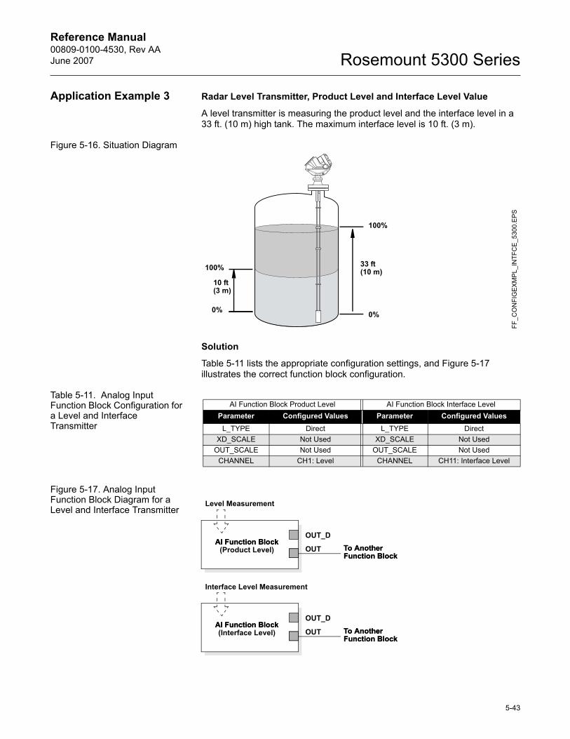
Reference Manual 00809-0100-4530, Rev AAJune 2007 Rosemount 5300 Series
Application Example 3 Radar Level Transmitter, Product Level and Interface Level Value
A level transmitter is measuring the product level and the interface level in a 33 ft. (10 m) high tank. The maximum interface level is 10 ft. (3 m).
Figure 5-16. Situation Diagram
Solution
Table 5-11 lists the appropriate configuration settings, and Figure 5-17 illustrates the correct function block configuration.
Table 5-11. Analog Input Function Block Configuration for a Level and Interface Transmitter
Figure 5-17. Analog Input Function Block Diagram for a Level and Interface Transmitter
10 ft(3 m)
100%
0%
FF_C
ON
FIG
EX
MP
L_IN
TFC
E_5
300.
EPS
33 ft(10 m)
100%
0%
AI Function Block Product Level AI Function Block Interface LevelParameter Configured Values Parameter Configured Values
L_TYPE Direct L_TYPE DirectXD_SCALE Not Used XD_SCALE Not Used
OUT_SCALE Not Used OUT_SCALE Not UsedCHANNEL CH1: Level CHANNEL CH11: Interface Level
Level Measurement
To Another Function Block
OUT_D
OUTAI Function BlockAI Function Block
(Product Level) To Another Function Block
To Another Function Block
OUT_D
OUTAI Function BlockAI Function Block(Interface Level) To Another
Function Block
Interface Level Measurement
5-43
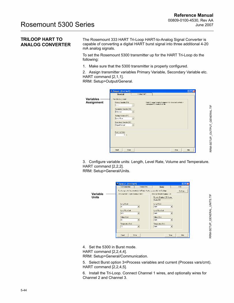
Reference Manual00809-0100-4530, Rev AA
June 2007Rosemount 5300 Series
TRILOOP HART TO ANALOG CONVERTER
The Rosemount 333 HART Tri-Loop HART-to-Analog Signal Converter is capable of converting a digital HART burst signal into three additional 4-20 mA analog signals.
To set the Rosemount 5300 transmitter up for the HART Tri-Loop do the following:
1. Make sure that the 5300 transmitter is properly configured.2. Assign transmitter variables Primary Variable, Secondary Variable etc.HART command [2,1,1].RRM: Setup>Output/General.
3. Configure variable units: Length, Level Rate, Volume and Temperature. HART command [2,2,2].RRM: Setup>General/Units.
4. Set the 5300 in Burst mode.HART command [2,2,4,4].RRM: Setup>General/Communication.5. Select Burst option 3=Process variables and current (Process vars/crnt).HART command [2,2,4,5].6. Install the Tri-Loop. Connect Channel 1 wires, and optionally wires for Channel 2 and Channel 3.
Variables Assignment
RR
M-S
ETU
P_O
UTP
UT_
GE
NER
AL.
TIF
Variable Units
RR
M-S
ETU
P_G
EN
ERA
L_U
NIT
S.TI
F
5-44
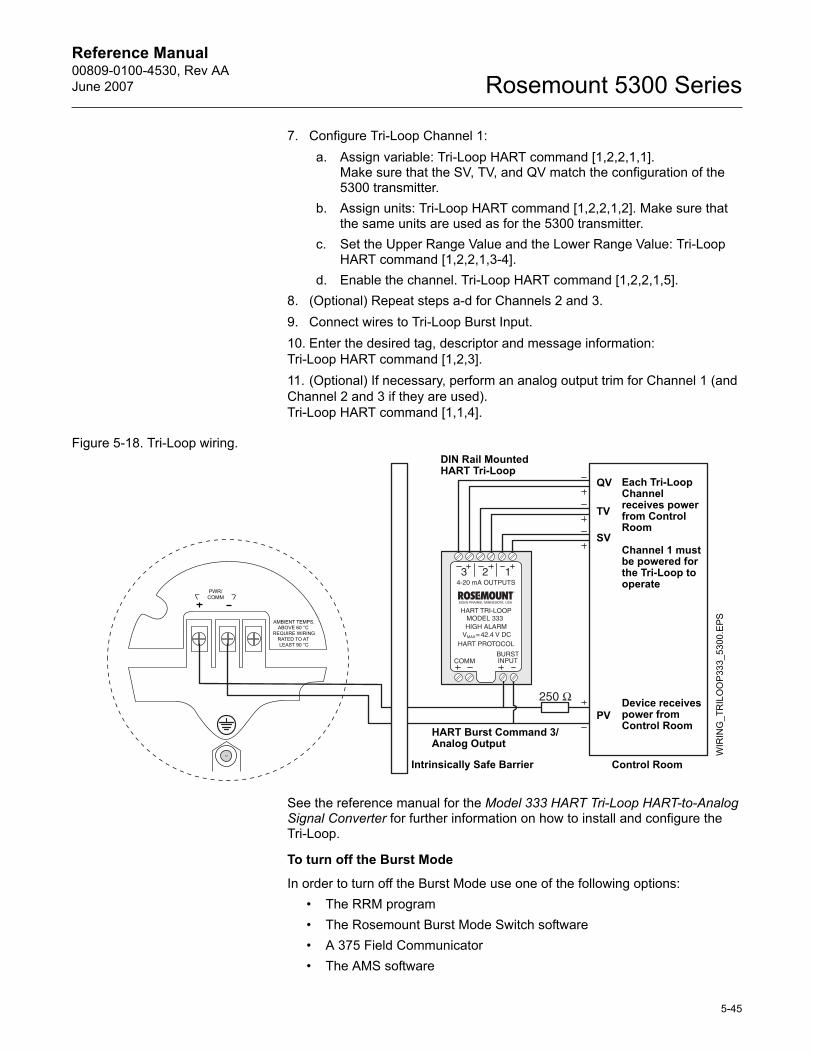
Reference Manual 00809-0100-4530, Rev AAJune 2007 Rosemount 5300 Series
7. Configure Tri-Loop Channel 1:a. Assign variable: Tri-Loop HART command [1,2,2,1,1].
Make sure that the SV, TV, and QV match the configuration of the 5300 transmitter.
b. Assign units: Tri-Loop HART command [1,2,2,1,2]. Make sure that the same units are used as for the 5300 transmitter.
c. Set the Upper Range Value and the Lower Range Value: Tri-Loop HART command [1,2,2,1,3-4].
d. Enable the channel. Tri-Loop HART command [1,2,2,1,5].8. (Optional) Repeat steps a-d for Channels 2 and 3.9. Connect wires to Tri-Loop Burst Input.10. Enter the desired tag, descriptor and message information:Tri-Loop HART command [1,2,3].11. (Optional) If necessary, perform an analog output trim for Channel 1 (and Channel 2 and 3 if they are used).Tri-Loop HART command [1,1,4].
Figure 5-18. Tri-Loop wiring.
See the reference manual for the Model 333 HART Tri-Loop HART-to-Analog Signal Converter for further information on how to install and configure the Tri-Loop.
To turn off the Burst Mode
In order to turn off the Burst Mode use one of the following options:� The RRM program� The Rosemount Burst Mode Switch software� A 375 Field Communicator� The AMS software
Each Tri-Loop Channel receives power from Control Room
Channel 1 must be powered for the Tri-Loop to operate
Device receives power from Control RoomHART Burst Command 3/
Analog Output
Intrinsically Safe Barrier
DIN Rail MountedHART Tri-Loop
Control Room
WIR
ING
_TR
ILO
OP
333_
5300
.EPS
QV
TV
SV
PV
5-45
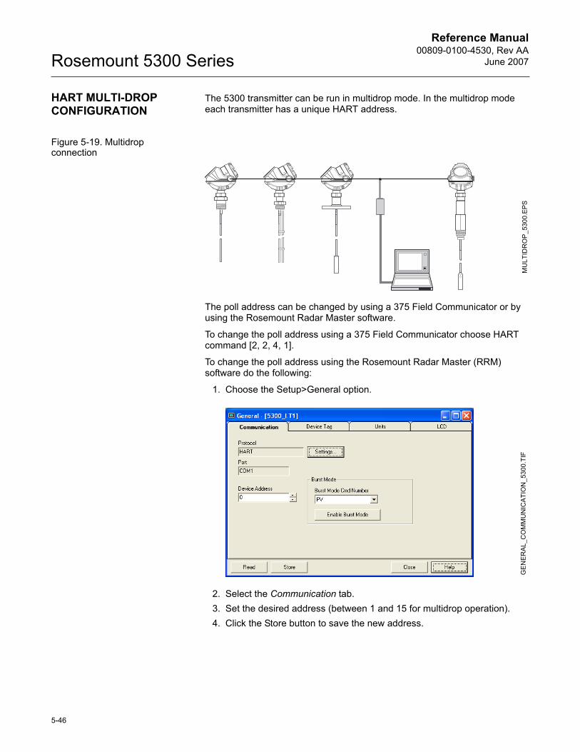
Reference Manual00809-0100-4530, Rev AA
June 2007Rosemount 5300 Series
HART MULTI-DROP CONFIGURATION
The 5300 transmitter can be run in multidrop mode. In the multidrop mode each transmitter has a unique HART address.
Figure 5-19. Multidrop connection
The poll address can be changed by using a 375 Field Communicator or by using the Rosemount Radar Master software.
To change the poll address using a 375 Field Communicator choose HART command [2, 2, 4, 1].
To change the poll address using the Rosemount Radar Master (RRM) software do the following:
1. Choose the Setup>General option.
2. Select the Communication tab.3. Set the desired address (between 1 and 15 for multidrop operation).4. Click the Store button to save the new address.
MU
LTID
RO
P_5
300.
EPS
GEN
ER
AL_
CO
MM
UN
ICAT
ION
_530
0.TI
F
5-46
Reference Manual 00809-0100-4530, Rev AAJune 2007 Rosemount 5300 Series
Section 6 Operation
Safety Messages . . . . . . . . . . . . . . . . . . . . . . . . . . . . . . . . . page 6-1Viewing Measurement Data . . . . . . . . . . . . . . . . . . . . . . . . page 6-2
SAFETY MESSAGES Procedures and instructions in this manual may require special precautions to ensure the safety of the personnel performing the operations. Information that raises potential safety issues is indicated by a warning symbol ( ). Refer to the safety messages listed at the beginning of each section before performing an operation preceded by this symbol.
Failure to follow these installation guidelines could result in death or serious injury.
� Make sure only qualified personnel perform the installation.
� Use the equipment only as specified in this manual. Failure to do so may impair the protection provided by the equipment.
Explosions could result in death or serious injury.� Verify that the operating environment of the transmitter is consistent with the
appropriate hazardous locations certifications.
� Before connecting a HART®-based communicator in an explosive atmosphere, make sure the instruments in the loop are installed in accordance with intrinsically safe or non-incendive field wiring practices.
Electrical shock could cause death or serious injury.� Use extreme caution when making contact with the leads and terminals.
High voltage that may be present on leads could cause electrical shock:� Probes covered with plastic and/or with plastic discs may generate an
ignition-capable level of electrostatic charge under certain extreme conditions. Therefore, when the probe is used in a potentially explosive atmosphere, appropriate measures must be taken to prevent electrostatic discharge.
Any substitution of non-recognized parts may jeopardize safety. Repair, e.g. substitution of components etc., may also jeopardize safety and is under no circumstances allowed.
www.rosemount.com
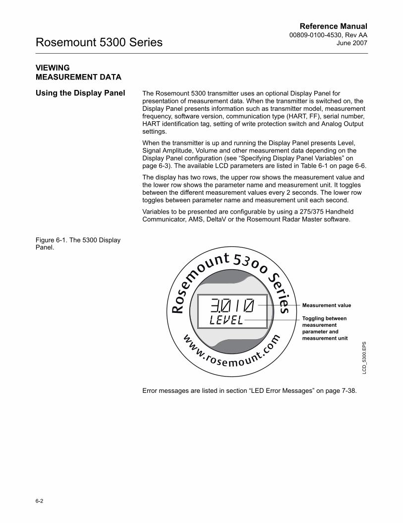
Reference Manual00809-0100-4530, Rev AA
June 2007Rosemount 5300 Series
VIEWING MEASUREMENT DATA
Using the Display Panel The Rosemount 5300 transmitter uses an optional Display Panel for presentation of measurement data. When the transmitter is switched on, the Display Panel presents information such as transmitter model, measurement frequency, software version, communication type (HART, FF), serial number, HART identification tag, setting of write protection switch and Analog Output settings.
When the transmitter is up and running the Display Panel presents Level, Signal Amplitude, Volume and other measurement data depending on the Display Panel configuration (see �Specifying Display Panel Variables� on page 6-3). The available LCD parameters are listed in Table 6-1 on page 6-6.
The display has two rows, the upper row shows the measurement value and the lower row shows the parameter name and measurement unit. It toggles between the different measurement values every 2 seconds. The lower row toggles between parameter name and measurement unit each second.
Variables to be presented are configurable by using a 275/375 Handheld Communicator, AMS, DeltaV or the Rosemount Radar Master software.
Figure 6-1. The 5300 Display Panel.
Error messages are listed in section �LED Error Messages� on page 7-38.
LCD
_530
0.E
PS
Measurement value
Toggling between measurement parameter and measurement unit
6-2
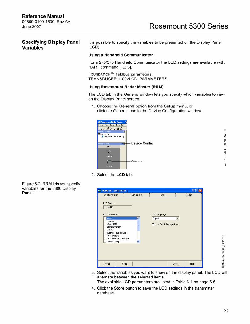
Reference Manual 00809-0100-4530, Rev AAJune 2007 Rosemount 5300 Series
Specifying Display Panel Variables
It is possible to specify the variables to be presented on the Display Panel (LCD).
Using a Handheld Communicator
For a 275/375 Handheld Communicator the LCD settings are available with: HART command [1,2,3].
FOUNDATIONTM fieldbus parameters:TRANSDUCER 1100>LCD_PARAMETERS.
Using Rosemount Radar Master (RRM)
The LCD tab in the General window lets you specify which variables to view on the Display Panel screen:
1. Choose the General option from the Setup menu, orclick the General icon in the Device Configuration window.
2. Select the LCD tab.
Figure 6-2. RRM lets you specify variables for the 5300 Display Panel.
3. Select the variables you want to show on the display panel. The LCD will alternate between the selected items.The available LCD parameters are listed in Table 6-1 on page 6-6.
4. Click the Store button to save the LCD settings in the transmitter database.
WO
RK
SPA
CE_
GE
NER
AL.
TIF
Device Config
General
RR
M/G
EN
ER
AL_
LCD
.TIF
6-3
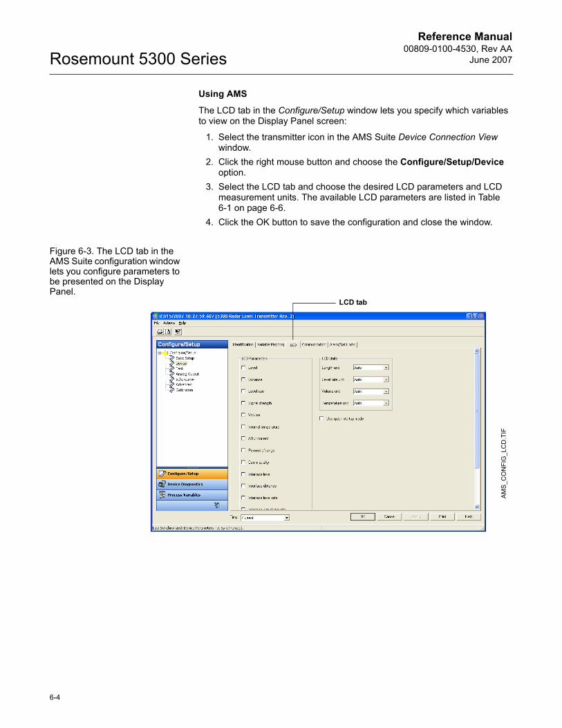
Reference Manual00809-0100-4530, Rev AA
June 2007Rosemount 5300 Series
Using AMS
The LCD tab in the Configure/Setup window lets you specify which variables to view on the Display Panel screen:
1. Select the transmitter icon in the AMS Suite Device Connection View window.
2. Click the right mouse button and choose the Configure/Setup/Device option.
3. Select the LCD tab and choose the desired LCD parameters and LCD measurement units. The available LCD parameters are listed in Table 6-1 on page 6-6.
4. Click the OK button to save the configuration and close the window.
Figure 6-3. The LCD tab in the AMS Suite configuration window lets you configure parameters to be presented on the Display Panel.
AMS
_CO
NFI
G_L
CD
.TIF
LCD tab
6-4
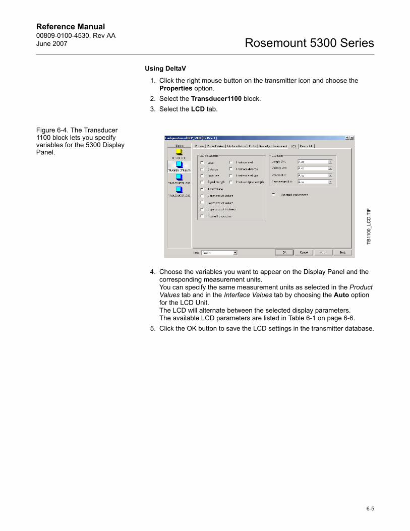
Reference Manual 00809-0100-4530, Rev AAJune 2007 Rosemount 5300 Series
Using DeltaV
1. Click the right mouse button on the transmitter icon and choose the Properties option.
2. Select the Transducer1100 block.3. Select the LCD tab.
Figure 6-4. The Transducer 1100 block lets you specify variables for the 5300 Display Panel.
4. Choose the variables you want to appear on the Display Panel and the corresponding measurement units. You can specify the same measurement units as selected in the Product Values tab and in the Interface Values tab by choosing the Auto option for the LCD Unit. The LCD will alternate between the selected display parameters.The available LCD parameters are listed in Table 6-1 on page 6-6.
5. Click the OK button to save the LCD settings in the transmitter database.
TB11
00_L
CD
.TIF
6-5
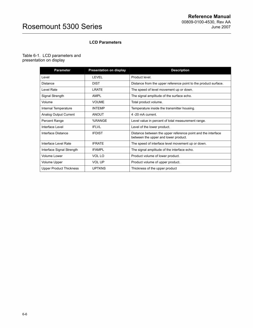
Reference Manual00809-0100-4530, Rev AA
June 2007Rosemount 5300 Series
LCD Parameters
Table 6-1. LCD parameters and presentation on display
Parameter Presentation on display Description
Level LEVEL Product level.
Distance DIST Distance from the upper reference point to the product surface.
Level Rate LRATE The speed of level movement up or down.
Signal Strength AMPL The signal amplitude of the surface echo.
Volume VOUME Total product volume.
Internal Temperature INTEMP Temperature inside the transmitter housing.
Analog Output Current ANOUT 4 -20 mA current.
Percent Range %RANGE Level value in percent of total measurement range.
Interface Level IFLVL Level of the lower product.
Interface Distance IFDIST Distance between the upper reference point and the interface between the upper and lower product.
Interface Level Rate IFRATE The speed of interface level movement up or down.
Interface Signal Strength IFAMPL The signal amplitude of the interface echo.
Volume Lower VOL LO Product volume of lower product.
Volume Upper VOL UP Product volume of upper product.
Upper Product Thickness UPTKNS Thickness of the upper product
6-6
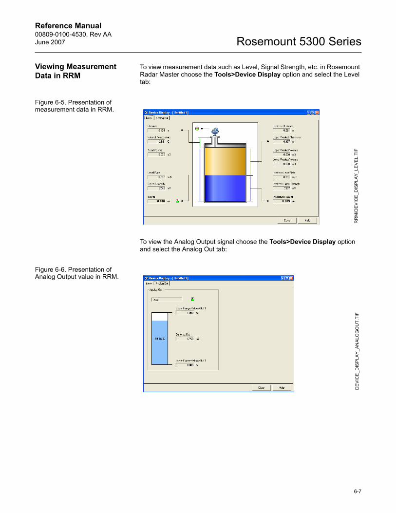
Reference Manual 00809-0100-4530, Rev AAJune 2007 Rosemount 5300 Series
Viewing Measurement Data in RRM
To view measurement data such as Level, Signal Strength, etc. in Rosemount Radar Master choose the Tools>Device Display option and select the Level tab:
Figure 6-5. Presentation of measurement data in RRM.
To view the Analog Output signal choose the Tools>Device Display option and select the Analog Out tab:
Figure 6-6. Presentation of Analog Output value in RRM.
RR
M/D
EVI
CE
_DIS
PLA
Y_LE
VEL.
TIF
DE
VIC
E_D
ISP
LAY
_AN
ALO
GO
UT.
TIF
6-7
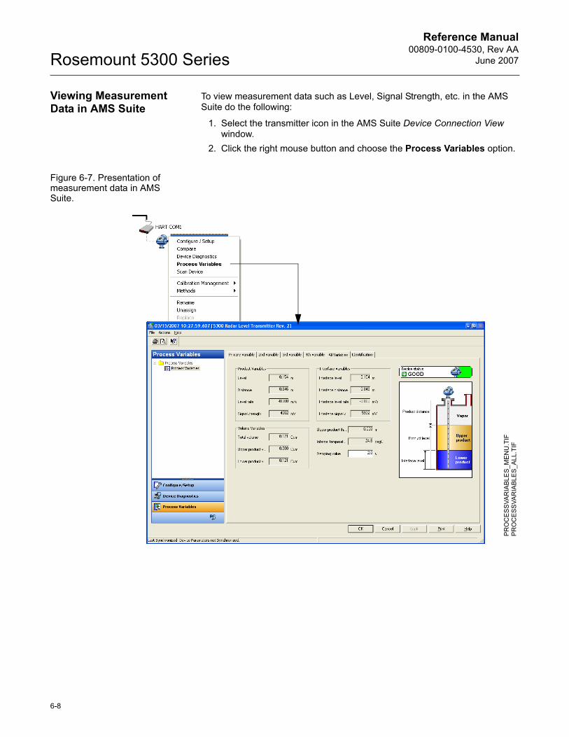
Reference Manual00809-0100-4530, Rev AA
June 2007Rosemount 5300 Series
Viewing Measurement Data in AMS Suite
To view measurement data such as Level, Signal Strength, etc. in the AMS Suite do the following:
1. Select the transmitter icon in the AMS Suite Device Connection View window.
2. Click the right mouse button and choose the Process Variables option.
Figure 6-7. Presentation of measurement data in AMS Suite.
PR
OC
ESS
VAR
IABL
ES_
ME
NU
.TIF
PR
OC
ESS
VAR
IABL
ES_
ALL
.TIF
6-8
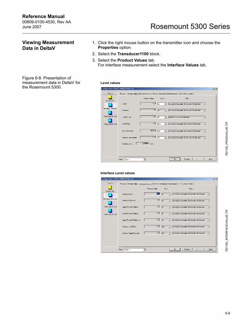
Reference Manual 00809-0100-4530, Rev AAJune 2007 Rosemount 5300 Series
Viewing Measurement Data in DeltaV
1. Click the right mouse button on the transmitter icon and choose the Properties option.
2. Select the Transducer1100 block.3. Select the Product Values tab.
For interface measurement select the Interface Values tab.
Figure 6-8. Presentation of measurement data in DeltaV for the Rosemount 5300.
TB11
00_P
RO
DVA
LUE
.TIF
TB11
00_I
NTE
RFA
CE
VAL
UE
.TIF
Level values
Interface Level values
6-9

Reference Manual00809-0100-4530, Rev AA
June 2007Rosemount 5300 Series
6-10
Reference Manual 00809-0100-4530, Rev AAJune 2007 Rosemount 5300 Series
Section 7 Service and Troubleshooting
Safety messages . . . . . . . . . . . . . . . . . . . . . . . . . . . . . . . . . page 7-1Analyzing the Measurement Signal . . . . . . . . . . . . . . . . . page 7-3Surface Pulse Not Found . . . . . . . . . . . . . . . . . . . . . . . . . . page 7-5Disturbance Echo Handling . . . . . . . . . . . . . . . . . . . . . . . . page 7-8Interface Pulse not Found . . . . . . . . . . . . . . . . . . . . . . . . . page 7-9Using the Echo Curve Analyzer . . . . . . . . . . . . . . . . . . . . page 7-11Interface Measurements with Fully Submerged Probes . page 7-16Analog Output Calibration . . . . . . . . . . . . . . . . . . . . . . . . . page 7-17Level and Distance Calibration . . . . . . . . . . . . . . . . . . . . . page 7-18Logging Measurement Data . . . . . . . . . . . . . . . . . . . . . . . . page 7-19Backing Up the Transmitter Configuration . . . . . . . . . . . page 7-20Diagnostics . . . . . . . . . . . . . . . . . . . . . . . . . . . . . . . . . . . . . page 7-23Configuration Report . . . . . . . . . . . . . . . . . . . . . . . . . . . . . page 7-21Reset to Factory Settings . . . . . . . . . . . . . . . . . . . . . . . . . page 7-22Using the Simulation Mode . . . . . . . . . . . . . . . . . . . . . . . . page 7-25Enter Service Mode in RRM . . . . . . . . . . . . . . . . . . . . . . . . page 7-26Write Protecting a Transmitter . . . . . . . . . . . . . . . . . . . . . page 7-26Viewing Input and Holding Registers . . . . . . . . . . . . . . . . page 7-27Removing the Transmitter Head . . . . . . . . . . . . . . . . . . . . page 7-28Changing the Probe . . . . . . . . . . . . . . . . . . . . . . . . . . . . . . page 7-29Diagnostic Messages . . . . . . . . . . . . . . . . . . . . . . . . . . . . . page 7-30LED Error Messages . . . . . . . . . . . . . . . . . . . . . . . . . . . . . . page 7-38
SAFETY MESSAGES Procedures and instructions in this section may require special precautions to ensure the safety of the personnel performing the operations. Information that raises potential safety issues is indicated by a warning symbol ( ). Please refer to the following safety messages before performing an operation preceded by this symbol..
www.rosemount.com
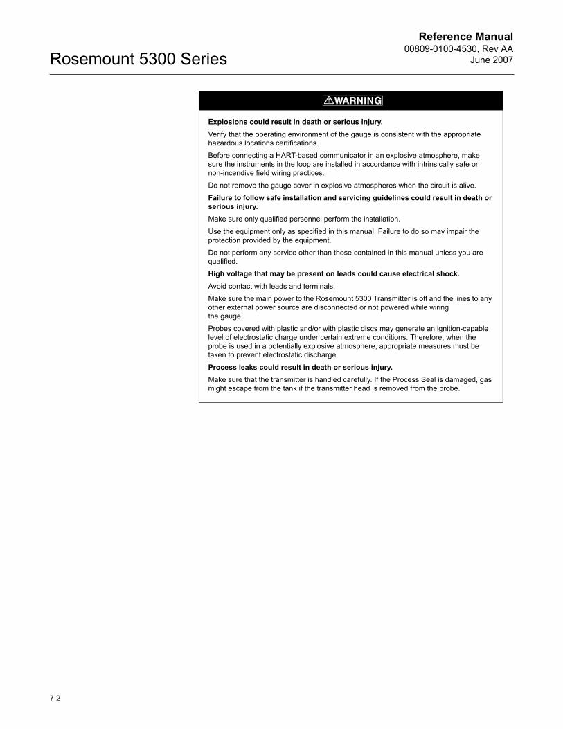
Reference Manual00809-0100-4530, Rev AA
June 2007Rosemount 5300 Series
Explosions could result in death or serious injury.Verify that the operating environment of the gauge is consistent with the appropriate hazardous locations certifications.
Before connecting a HART-based communicator in an explosive atmosphere, make sure the instruments in the loop are installed in accordance with intrinsically safe or non-incendive field wiring practices.
Do not remove the gauge cover in explosive atmospheres when the circuit is alive.
Failure to follow safe installation and servicing guidelines could result in death or serious injury.Make sure only qualified personnel perform the installation.
Use the equipment only as specified in this manual. Failure to do so may impair the protection provided by the equipment.
Do not perform any service other than those contained in this manual unless you are qualified.
High voltage that may be present on leads could cause electrical shock.Avoid contact with leads and terminals.
Make sure the main power to the Rosemount 5300 Transmitter is off and the lines to any other external power source are disconnected or not powered while wiringthe gauge.
Probes covered with plastic and/or with plastic discs may generate an ignition-capable level of electrostatic charge under certain extreme conditions. Therefore, when the probe is used in a potentially explosive atmosphere, appropriate measures must be taken to prevent electrostatic discharge.
Process leaks could result in death or serious injury.Make sure that the transmitter is handled carefully. If the Process Seal is damaged, gas might escape from the tank if the transmitter head is removed from the probe.
7-2
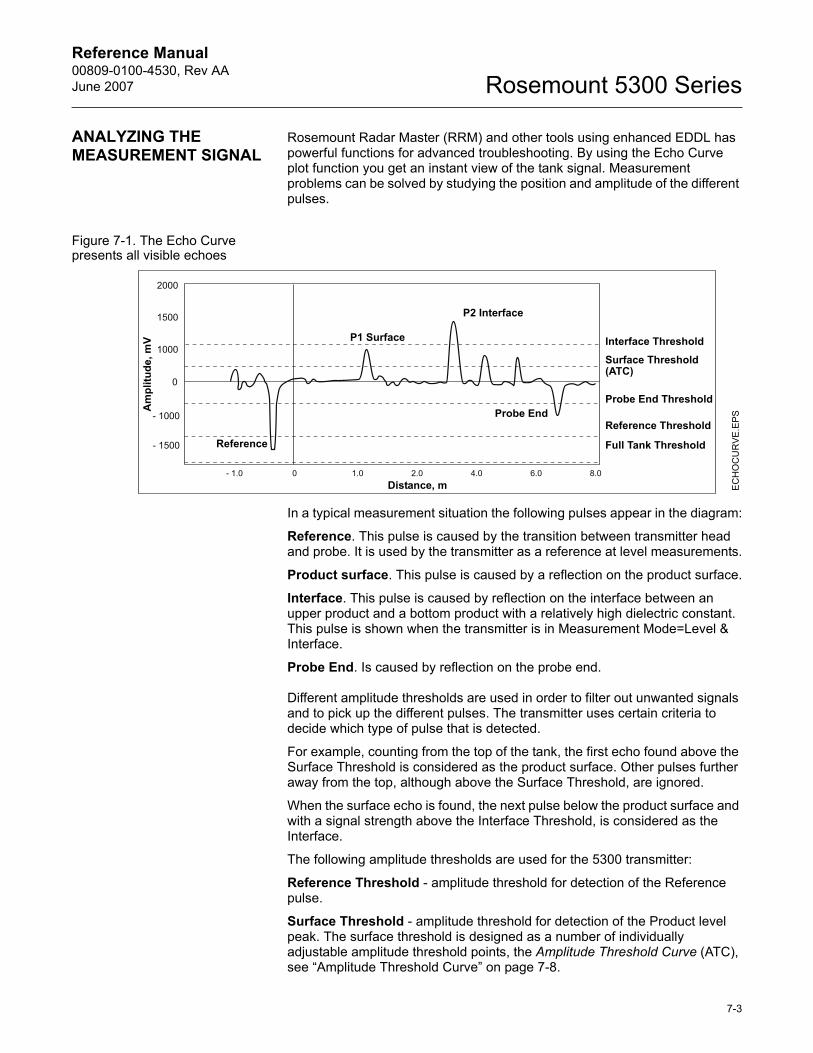
Reference Manual 00809-0100-4530, Rev AAJune 2007 Rosemount 5300 Series
ANALYZING THE MEASUREMENT SIGNAL
Rosemount Radar Master (RRM) and other tools using enhanced EDDL has powerful functions for advanced troubleshooting. By using the Echo Curve plot function you get an instant view of the tank signal. Measurement problems can be solved by studying the position and amplitude of the different pulses.
Figure 7-1. The Echo Curve presents all visible echoes
In a typical measurement situation the following pulses appear in the diagram:
Reference. This pulse is caused by the transition between transmitter head and probe. It is used by the transmitter as a reference at level measurements.
Product surface. This pulse is caused by a reflection on the product surface.
Interface. This pulse is caused by reflection on the interface between an upper product and a bottom product with a relatively high dielectric constant. This pulse is shown when the transmitter is in Measurement Mode=Level & Interface.
Probe End. Is caused by reflection on the probe end.
Different amplitude thresholds are used in order to filter out unwanted signals and to pick up the different pulses. The transmitter uses certain criteria to decide which type of pulse that is detected.
For example, counting from the top of the tank, the first echo found above the Surface Threshold is considered as the product surface. Other pulses further away from the top, although above the Surface Threshold, are ignored.
When the surface echo is found, the next pulse below the product surface and with a signal strength above the Interface Threshold, is considered as the Interface.
The following amplitude thresholds are used for the 5300 transmitter:
Reference Threshold - amplitude threshold for detection of the Reference pulse.
Surface Threshold - amplitude threshold for detection of the Product level peak. The surface threshold is designed as a number of individually adjustable amplitude threshold points, the Amplitude Threshold Curve (ATC), see �Amplitude Threshold Curve� on page 7-8.
EC
HO
CU
RVE
.EPS
Interface Threshold
Surface Threshold(ATC)
Probe End Threshold
Reference Threshold
Full Tank Threshold
Am
plitu
de, m
V
Distance, m
Reference
P1 Surface
P2 Interface
Probe End
7-3

Reference Manual00809-0100-4530, Rev AA
June 2007Rosemount 5300 Series
Interface Threshold - amplitude threshold for detection of the Interface level peak.
Full Tank Threshold - amplitude threshold that can be used to detect whether the probe is fully submerged in the upper product or not.
Probe End Threshold - amplitude threshold for detection of the Probe End peak.
Thresholds are recommended to be set to approximately 50% of the signal peak amplitude. To adjust the Amplitude Thresholds see �Using the Echo Curve Analyzer� on page 7-11.
7-4
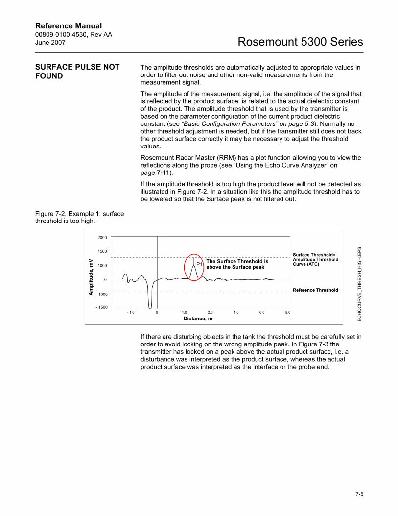
Reference Manual 00809-0100-4530, Rev AAJune 2007 Rosemount 5300 Series
SURFACE PULSE NOT FOUND
The amplitude thresholds are automatically adjusted to appropriate values in order to filter out noise and other non-valid measurements from the measurement signal.
The amplitude of the measurement signal, i.e. the amplitude of the signal that is reflected by the product surface, is related to the actual dielectric constant of the product. The amplitude threshold that is used by the transmitter is based on the parameter configuration of the current product dielectric constant (see �Basic Configuration Parameters� on page 5-3). Normally no other threshold adjustment is needed, but if the transmitter still does not track the product surface correctly it may be necessary to adjust the threshold values.
Rosemount Radar Master (RRM) has a plot function allowing you to view the reflections along the probe (see �Using the Echo Curve Analyzer� on page 7-11).
If the amplitude threshold is too high the product level will not be detected as illustrated in Figure 7-2. In a situation like this the amplitude threshold has to be lowered so that the Surface peak is not filtered out.
Figure 7-2. Example 1: surface threshold is too high.
If there are disturbing objects in the tank the threshold must be carefully set in order to avoid locking on the wrong amplitude peak. In Figure 7-3 the transmitter has locked on a peak above the actual product surface, i.e. a disturbance was interpreted as the product surface, whereas the actual product surface was interpreted as the interface or the probe end.
The Surface Threshold is above the Surface peak
EC
HO
CU
RVE
_TH
RE
SH
_HIG
H.E
PS
Surface Threshold=Amplitude Threshold Curve (ATC)
Reference Threshold
Am
plitu
de, m
V
Distance, m
7-5
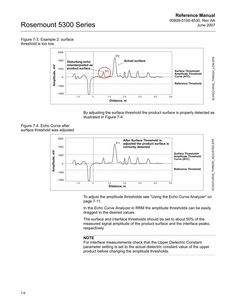
Reference Manual00809-0100-4530, Rev AA
June 2007Rosemount 5300 Series
Figure 7-3. Example 2: surface threshold is too low.
By adjusting the surface threshold the product surface is properly detected as illustrated in Figure 7-4:
Figure 7-4. Echo Curve after surface threshold was adjusted
To adjust the amplitude thresholds see �Using the Echo Curve Analyzer� on page 7-11.
In the Echo Curve Analyzer in RRM the amplitude thresholds can be easily dragged to the desired values.
The surface and interface thresholds should be set to about 50% of the measured signal amplitude of the product surface and the interface peaks, respectively.
NOTEFor interface measurements check that the Upper Dielectric Constant parameter setting is set to the actual dielectric constant value of the upper product before changing the amplitude thresholds.
Actual surfaceDisturbing echo misinterpreted as product surface
EC
HO
CU
RV
E_TH
RE
SH
_LO
W.E
PS
Am
plitu
de, m
V
Distance, m
Reference Threshold
Surface Threshold=Amplitude Threshold Curve (ATC)
After Surface Threshold is adjusted the product surface is correctly detected
ECH
OC
UR
VE_T
HR
ESH
_AD
JUS
TED
.EPS
Am
plitu
de, m
V
Distance, m
Reference Threshold
Surface Threshold=Amplitude Threshold Curve (ATC)
7-6
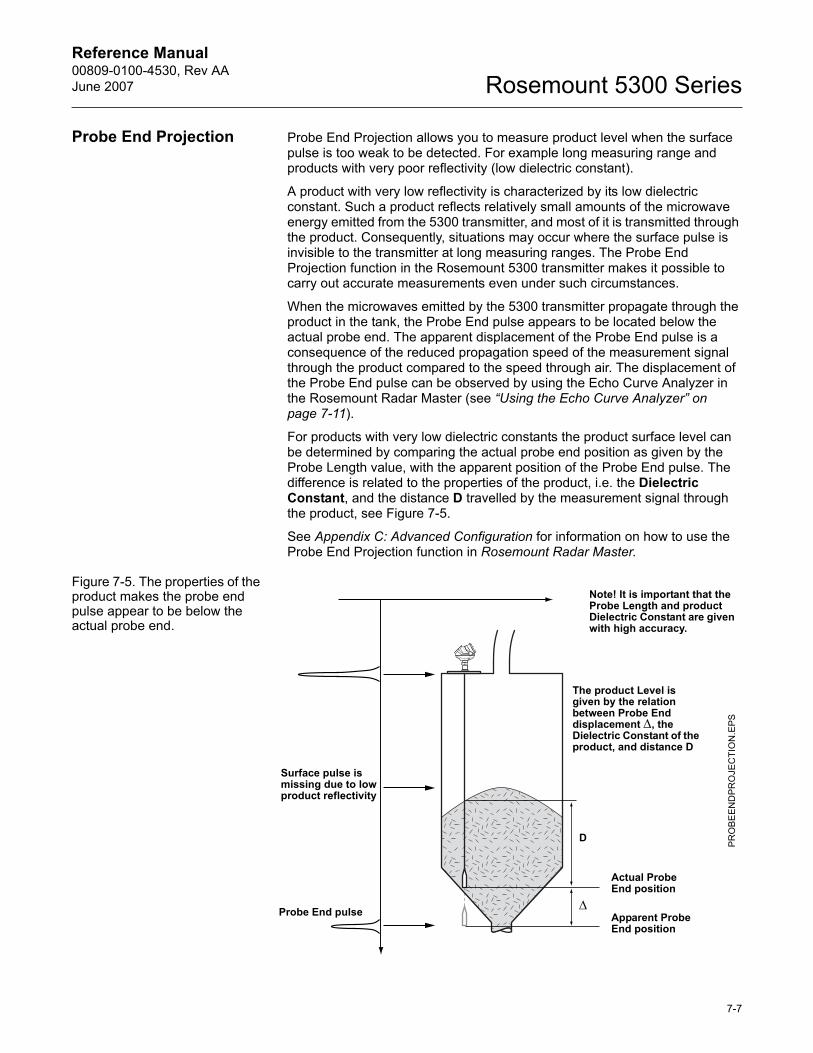
Reference Manual 00809-0100-4530, Rev AAJune 2007 Rosemount 5300 Series
Probe End Projection Probe End Projection allows you to measure product level when the surface pulse is too weak to be detected. For example long measuring range and products with very poor reflectivity (low dielectric constant).
A product with very low reflectivity is characterized by its low dielectric constant. Such a product reflects relatively small amounts of the microwave energy emitted from the 5300 transmitter, and most of it is transmitted through the product. Consequently, situations may occur where the surface pulse is invisible to the transmitter at long measuring ranges. The Probe End Projection function in the Rosemount 5300 transmitter makes it possible to carry out accurate measurements even under such circumstances.
When the microwaves emitted by the 5300 transmitter propagate through the product in the tank, the Probe End pulse appears to be located below the actual probe end. The apparent displacement of the Probe End pulse is a consequence of the reduced propagation speed of the measurement signal through the product compared to the speed through air. The displacement of the Probe End pulse can be observed by using the Echo Curve Analyzer in the Rosemount Radar Master (see �Using the Echo Curve Analyzer� on page 7-11).
For products with very low dielectric constants the product surface level can be determined by comparing the actual probe end position as given by the Probe Length value, with the apparent position of the Probe End pulse. The difference is related to the properties of the product, i.e. the Dielectric Constant, and the distance D travelled by the measurement signal through the product, see Figure 7-5.
See Appendix C: Advanced Configuration for information on how to use the Probe End Projection function in Rosemount Radar Master.
Figure 7-5. The properties of the product makes the probe end pulse appear to be below the actual probe end.
PR
OBE
EN
DP
RO
JEC
TIO
N.E
PS
Apparent Probe End position
Surface pulse is missing due to low product reflectivity
Actual Probe End position
D
Probe End pulse Δ
The product Level is given by the relation between Probe End displacement Δ, the Dielectric Constant of the product, and distance D
Note! It is important that the Probe Length and product Dielectric Constant are given with high accuracy.
7-7
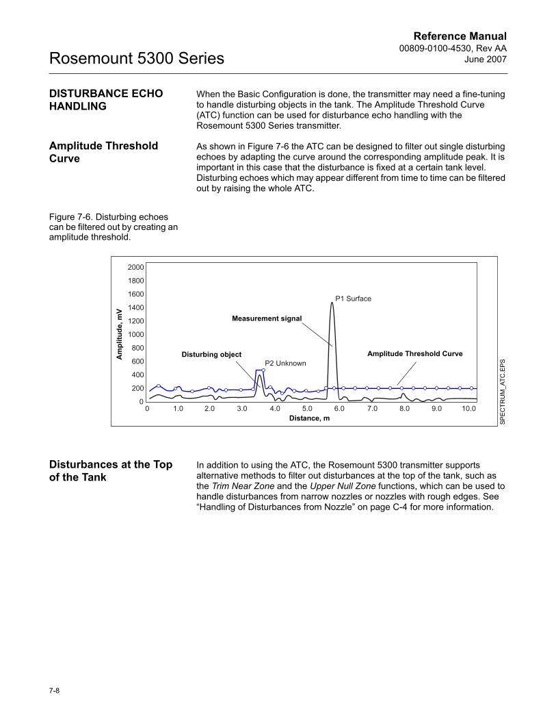
Reference Manual00809-0100-4530, Rev AA
June 2007Rosemount 5300 Series
DISTURBANCE ECHO HANDLING
When the Basic Configuration is done, the transmitter may need a fine-tuning to handle disturbing objects in the tank. The Amplitude Threshold Curve (ATC) function can be used for disturbance echo handling with the Rosemount 5300 Series transmitter.
Amplitude Threshold Curve
As shown in Figure 7-6 the ATC can be designed to filter out single disturbing echoes by adapting the curve around the corresponding amplitude peak. It is important in this case that the disturbance is fixed at a certain tank level. Disturbing echoes which may appear different from time to time can be filtered out by raising the whole ATC.
Figure 7-6. Disturbing echoes can be filtered out by creating an amplitude threshold.
Disturbances at the Top of the Tank
In addition to using the ATC, the Rosemount 5300 transmitter supports alternative methods to filter out disturbances at the top of the tank, such as the Trim Near Zone and the Upper Null Zone functions, which can be used to handle disturbances from narrow nozzles or nozzles with rough edges. See �Handling of Disturbances from Nozzle� on page C-4 for more information.
SPE
CTR
UM
_ATC
.EPS
Amplitude Threshold Curve
Measurement signal
Am
plitu
de, m
V
Distance, m
Disturbing object
7-8
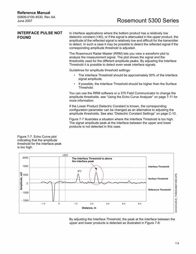
Reference Manual 00809-0100-4530, Rev AAJune 2007 Rosemount 5300 Series
INTERFACE PULSE NOT FOUND
In interface applications where the bottom product has a relatively low dielectric constant (<40), or if the signal is attenuated in the upper product, the amplitude of the reflected signal is relatively low and difficult for the transmitter to detect. In such a case it may be possible to detect the reflected signal if the corresponding amplitude threshold is adjusted.
The Rosemount Radar Master (RRM) lets you view a waveform plot to analyze the measurement signal. The plot shows the signal and the thresholds used for the different amplitude peaks. By adjusting the Interface Threshold it is possible to detect even weak interface signals.
Guidelines for amplitude threshold settings:� The Interface Threshold should be approximately 50% of the interface
signal amplitude.� If possible, the Interface Threshold should be higher than the Surface
Threshold.
You can use the RRM software or a 375 Field Communicator to change the amplitude thresholds, see �Using the Echo Curve Analyzer� on page 7-11 for more information.
If the Lower Product Dielectric Constant is known, the corresponding configuration parameter can be changed as an alternative to adjusting the amplitude thresholds. See also �Dielectric Constant Settings� on page C-10.
Figure 7-7 illustrates a situation where the Interface Threshold is too high. The signal amplitude peak at the interface between the upper and lower products is not detected in this case.
Figure 7-7. Echo Curve plot indicating that the amplitude threshold for the interface peak is too high.
By adjusting the Interface Threshold, the peak at the interface between the upper and lower products is detected as illustrated in Figure 7-8:
The Interface Threshold is above the interface peak
EC
HO
CU
RV
E_T
HR
ESH
BE
FOR
E.EP
S
Am
plitu
de, m
V
Distance, m
Interface Threshold
Surface Threshold
Reference Threshold
7-9
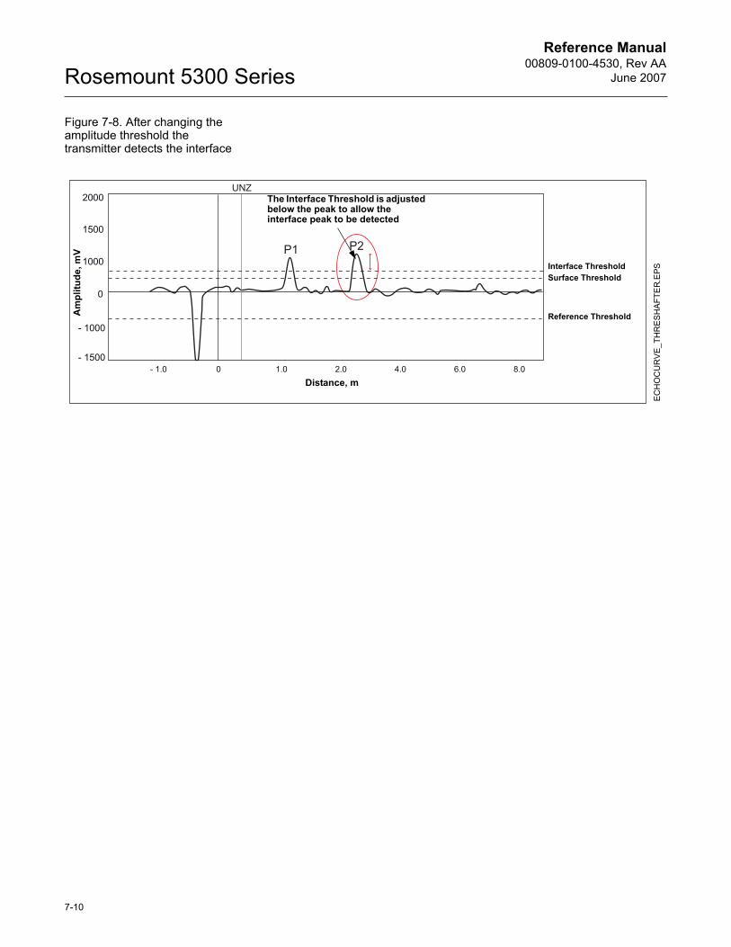
Reference Manual00809-0100-4530, Rev AA
June 2007Rosemount 5300 Series
Figure 7-8. After changing the amplitude threshold the transmitter detects the interface
The Interface Threshold is adjusted below the peak to allow the interface peak to be detected
ECH
OC
UR
VE
_TH
RE
SHA
FTE
R.EP
S
Am
plitu
de, m
V
Distance, m
Interface ThresholdSurface Threshold
Reference Threshold
7-10
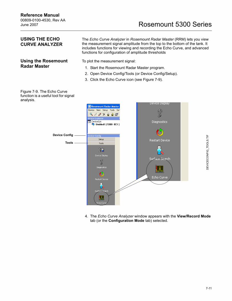
Reference Manual 00809-0100-4530, Rev AAJune 2007 Rosemount 5300 Series
USING THE ECHO CURVE ANALYZER
The Echo Curve Analyzer in Rosemount Radar Master (RRM) lets you view the measurement signal amplitude from the top to the bottom of the tank. It includes functions for viewing and recording the Echo Curve, and advanced functions for configuration of amplitude thresholds
Using the Rosemount Radar Master
To plot the measurement signal:
1. Start the Rosemount Radar Master program.2. Open Device Config/Tools (or Device Config/Setup).3. Click the Echo Curve icon (see Figure 7-9).
Figure 7-9. The Echo Curve function is a useful tool for signal analysis.
4. The Echo Curve Analyzer window appears with the View/Record Mode tab (or the Configuration Mode tab) selected.
DEV
ICE
CO
NFI
G_T
OO
LS.T
IF
Tools
Device Config
7-11
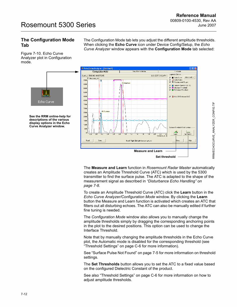
Reference Manual00809-0100-4530, Rev AA
June 2007Rosemount 5300 Series
The Configuration Mode Tab
The Configuration Mode tab lets you adjust the different amplitude thresholds. When clicking the Echo Curve icon under Device Config/Setup, the Echo Curve Analyzer window appears with the Configuration Mode tab selected:
Figure 7-10. Echo Curve Analyzer plot in Configuration mode.
The Measure and Learn function in Rosemount Radar Master automatically creates an Amplitude Threshold Curve (ATC) which is used by the 5300 transmitter to find the surface pulse. The ATC is adapted to the shape of the measurement signal as described in �Disturbance Echo Handling� on page 7-8.
To create an Amplitude Threshold Curve (ATC) click the Learn button in the Echo Curve Analyzer/Configuration Mode window. By clicking the Learn button the Measure and Learn function is activated which creates an ATC that filters out all disturbing echoes. The ATC can also be manually edited if further fine tuning is needed.
The Configuration Mode window also allows you to manually change the amplitude thresholds simply by dragging the corresponding anchoring points in the plot to the desired positions. This option can be used to change the Interface Threshold.
Note that by manually changing the amplitude thresholds in the Echo Curve plot, the Automatic mode is disabled for the corresponding threshold (see �Threshold Settings� on page C-6 for more information).
See �Surface Pulse Not Found� on page 7-5 for more information on threshold settings.
The Set Thresholds button allows you to set the ATC to a fixed value based on the configured Dielectric Constant of the product.
See also �Threshold Settings� on page C-6 for more information on how to adjust amplitude thresholds.
RR
M/E
CH
OC
UR
VE_A
NAL
YZE
R_C
ON
FIG
.TIF
Set threshold
Measure and Learn
See the RRM online-help for descriptions of the various display options in the Echo Curve Analyzer window.
7-12
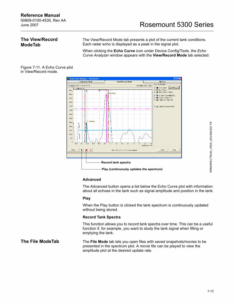
Reference Manual 00809-0100-4530, Rev AAJune 2007 Rosemount 5300 Series
The View/Record ModeTab
The View/Record Mode tab presents a plot of the current tank conditions. Each radar echo is displayed as a peak in the signal plot.
When clicking the Echo Curve icon under Device Config/Tools, the Echo Curve Analyzer window appears with the View/Record Mode tab selected:
Figure 7-11. A Echo Curve plot in View/Record mode.
Advanced
The Advanced button opens a list below the Echo Curve plot with information about all echoes in the tank such as signal amplitude and position in the tank.
Play
When the Play button is clicked the tank spectrum is continuously updated without being stored.
Record Tank Spectra
This function allows you to record tank spectra over time. This can be a useful function if, for example, you want to study the tank signal when filling or emptying the tank.
The File ModeTab The File Mode tab lets you open files with saved snapshots/movies to be presented in the spectrum plot. A movie file can be played to view the amplitude plot at the desired update rate.
RR
M/S
PEC
TRU
M_V
IEW
_AD
VA
NC
ED
.TIF
Record tank spectra
Play (continuously updates the spectrum)
7-13
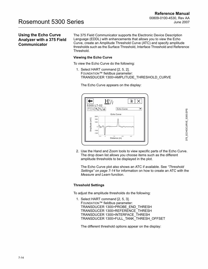
Reference Manual00809-0100-4530, Rev AA
June 2007Rosemount 5300 Series
Using the Echo Curve Analyzer with a 375 Field Communicator
The 375 Field Communicator supports the Electronic Device Description Language (EDDL) with enhancements that allows you to view the Echo Curve, create an Amplitude Threshold Curve (ATC) and specify amplitude thresholds such as the Surface Threshold, Interface Threshold and Reference Threshold.
Viewing the Echo Curve
To view the Echo Curve do the following:
1. Select HART command [2, 5, 2].FOUNDATION� fieldbus parameter:TRANSDUCER 1300>AMPLITUDE_THRESHOLD_CURVE
The Echo Curve appears on the display:
2. Use the Hand and Zoom tools to view specific parts of the Echo Curve. The drop down list allows you choose items such as the different amplitude thresholds to be displayed in the plot.
The Echo Curve plot also shows an ATC if available. See �Threshold Settings� on page 7-14 for information on how to create an ATC with the Measure and Learn function.
Threshold Settings
To adjust the amplitude thresholds do the following:
1. Select HART command [2, 5, 3].FOUNDATION� fieldbus parameter:TRANSDUCER 1300>PROBE_END_THRESHTRANSDUCER 1300>REFERENCE_THRESHTRANSDUCER 1300>INTERFACE_THRESHTRANSDUCER 1300>FULL_TANK_THRESH_OFFSET
The different threshold options appear on the display:
375_
ECH
OC
UR
VE_5
300.
EPS
7-14
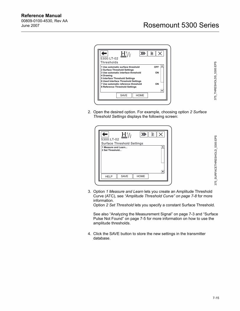
Reference Manual 00809-0100-4530, Rev AAJune 2007 Rosemount 5300 Series
2. Open the desired option. For example, choosing option 2 Surface Threshold Settings displays the following screen:
3. Option 1 Measure and Learn lets you create an Amplitude Threshold Curve (ATC), see �Amplitude Threshold Curve� on page 7-8 for more information.Option 2 Set Threshold lets you specify a constant Surface Threshold.
See also �Analyzing the Measurement Signal� on page 7-3 and �Surface Pulse Not Found� on page 7-5 for more information on how to use the amplitude thresholds.
4. Click the SAVE button to store the new settings in the transmitter database.
375_
THR
ES
HO
LDS
_530
0.E
PS37
5_S
UR
FAC
ETH
RE
SHO
LD_5
300.
EPS
7-15
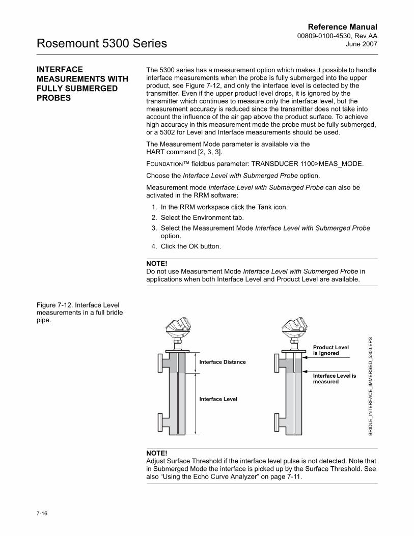
Reference Manual00809-0100-4530, Rev AA
June 2007Rosemount 5300 Series
INTERFACE MEASUREMENTS WITH FULLY SUBMERGED PROBES
The 5300 series has a measurement option which makes it possible to handle interface measurements when the probe is fully submerged into the upper product, see Figure 7-12, and only the interface level is detected by the transmitter. Even if the upper product level drops, it is ignored by the transmitter which continues to measure only the interface level, but the measurement accuracy is reduced since the transmitter does not take into account the influence of the air gap above the product surface. To achieve high accuracy in this measurement mode the probe must be fully submerged, or a 5302 for Level and Interface measurements should be used.
The Measurement Mode parameter is available via the HART command [2, 3, 3].
FOUNDATION� fieldbus parameter: TRANSDUCER 1100>MEAS_MODE.
Choose the Interface Level with Submerged Probe option.
Measurement mode Interface Level with Submerged Probe can also be activated in the RRM software:
1. In the RRM workspace click the Tank icon.2. Select the Environment tab.3. Select the Measurement Mode Interface Level with Submerged Probe
option.4. Click the OK button.
NOTE!Do not use Measurement Mode Interface Level with Submerged Probe in applications when both Interface Level and Product Level are available.
Figure 7-12. Interface Level measurements in a full bridle pipe.
NOTE!Adjust Surface Threshold if the interface level pulse is not detected. Note that in Submerged Mode the interface is picked up by the Surface Threshold. See also �Using the Echo Curve Analyzer� on page 7-11.
Interface Distance
Interface Level
Product Level is ignored
Interface Level is measured
BRID
LE_I
NTE
RFA
CE_
IMM
ER
SE
D_5
300.
EPS
7-16
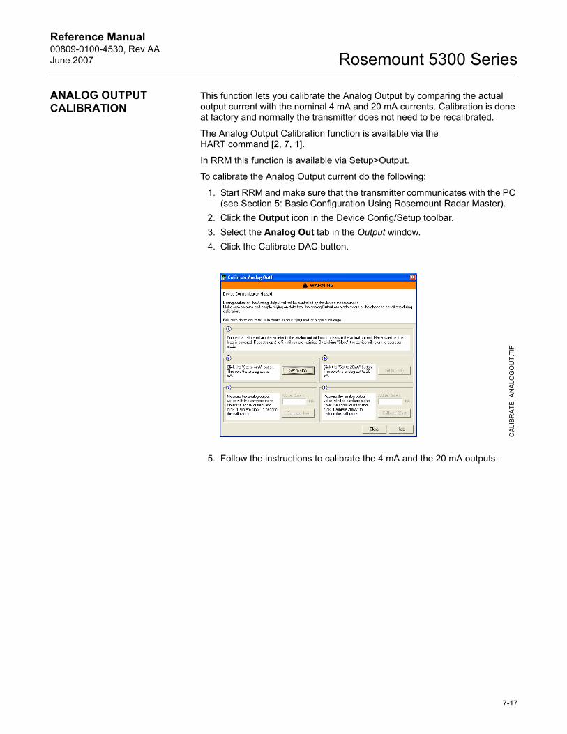
Reference Manual 00809-0100-4530, Rev AAJune 2007 Rosemount 5300 Series
ANALOG OUTPUT CALIBRATION
This function lets you calibrate the Analog Output by comparing the actual output current with the nominal 4 mA and 20 mA currents. Calibration is done at factory and normally the transmitter does not need to be recalibrated.
The Analog Output Calibration function is available via the HART command [2, 7, 1].
In RRM this function is available via Setup>Output.
To calibrate the Analog Output current do the following:
1. Start RRM and make sure that the transmitter communicates with the PC (see Section 5: Basic Configuration Using Rosemount Radar Master).
2. Click the Output icon in the Device Config/Setup toolbar.3. Select the Analog Out tab in the Output window.4. Click the Calibrate DAC button.
5. Follow the instructions to calibrate the 4 mA and the 20 mA outputs.
CA
LIB
RAT
E_A
NAL
OG
OU
T.TI
F
7-17
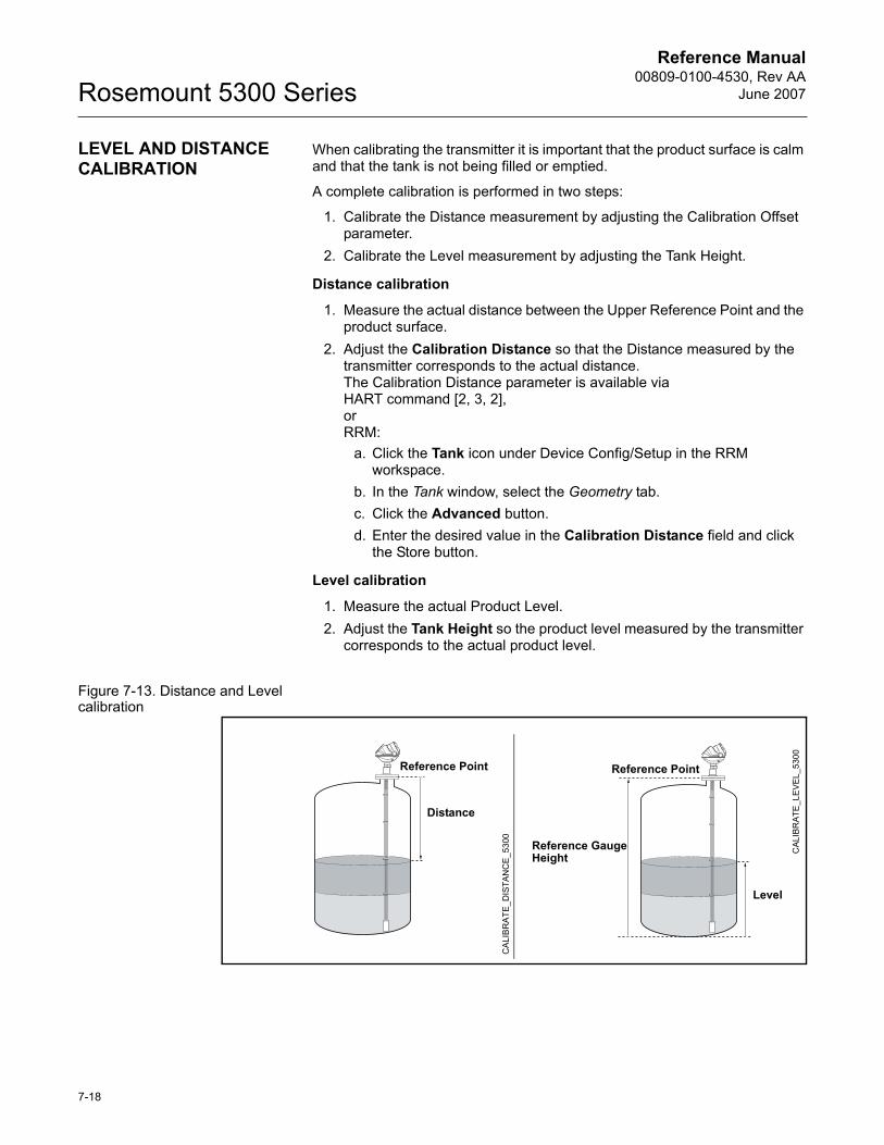
Reference Manual00809-0100-4530, Rev AA
June 2007Rosemount 5300 Series
LEVEL AND DISTANCE CALIBRATION
When calibrating the transmitter it is important that the product surface is calm and that the tank is not being filled or emptied.
A complete calibration is performed in two steps:
1. Calibrate the Distance measurement by adjusting the Calibration Offset parameter.
2. Calibrate the Level measurement by adjusting the Tank Height.
Distance calibration
1. Measure the actual distance between the Upper Reference Point and the product surface.
2. Adjust the Calibration Distance so that the Distance measured by the transmitter corresponds to the actual distance. The Calibration Distance parameter is available via HART command [2, 3, 2],orRRM:
a. Click the Tank icon under Device Config/Setup in the RRM workspace.
b. In the Tank window, select the Geometry tab.c. Click the Advanced button.d. Enter the desired value in the Calibration Distance field and click
the Store button.
Level calibration
1. Measure the actual Product Level.2. Adjust the Tank Height so the product level measured by the transmitter
corresponds to the actual product level.
Figure 7-13. Distance and Level calibration
Level
Reference Point
Reference Gauge Height
Distance
Reference Point
CAL
IBR
ATE
_LE
VEL_
5300
CA
LIB
RA
TE_D
ISTA
NC
E_5
300
7-18
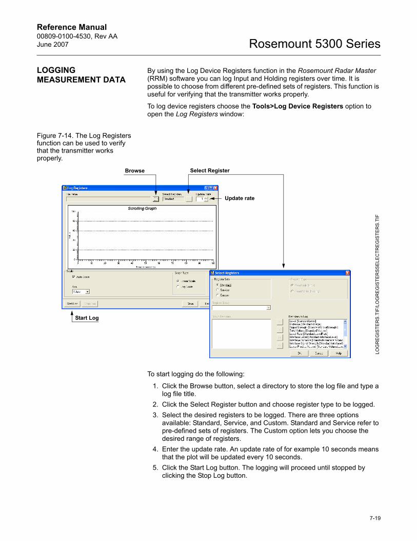
Reference Manual 00809-0100-4530, Rev AAJune 2007 Rosemount 5300 Series
LOGGING MEASUREMENT DATA
By using the Log Device Registers function in the Rosemount Radar Master (RRM) software you can log Input and Holding registers over time. It is possible to choose from different pre-defined sets of registers. This function is useful for verifying that the transmitter works properly.
To log device registers choose the Tools>Log Device Registers option to open the Log Registers window:
Figure 7-14. The Log Registers function can be used to verify that the transmitter works properly.
To start logging do the following:
1. Click the Browse button, select a directory to store the log file and type a log file title.
2. Click the Select Register button and choose register type to be logged.3. Select the desired registers to be logged. There are three options
available: Standard, Service, and Custom. Standard and Service refer to pre-defined sets of registers. The Custom option lets you choose the desired range of registers.
4. Enter the update rate. An update rate of for example 10 seconds means that the plot will be updated every 10 seconds.
5. Click the Start Log button. The logging will proceed until stopped by clicking the Stop Log button.
LOG
RE
GIS
TER
S.T
IF/L
OG
RE
GIS
TER
SS
ELE
CTR
EG
ISTE
RS
.TIF
Start Log
Browse Select Register
Update rate
7-19
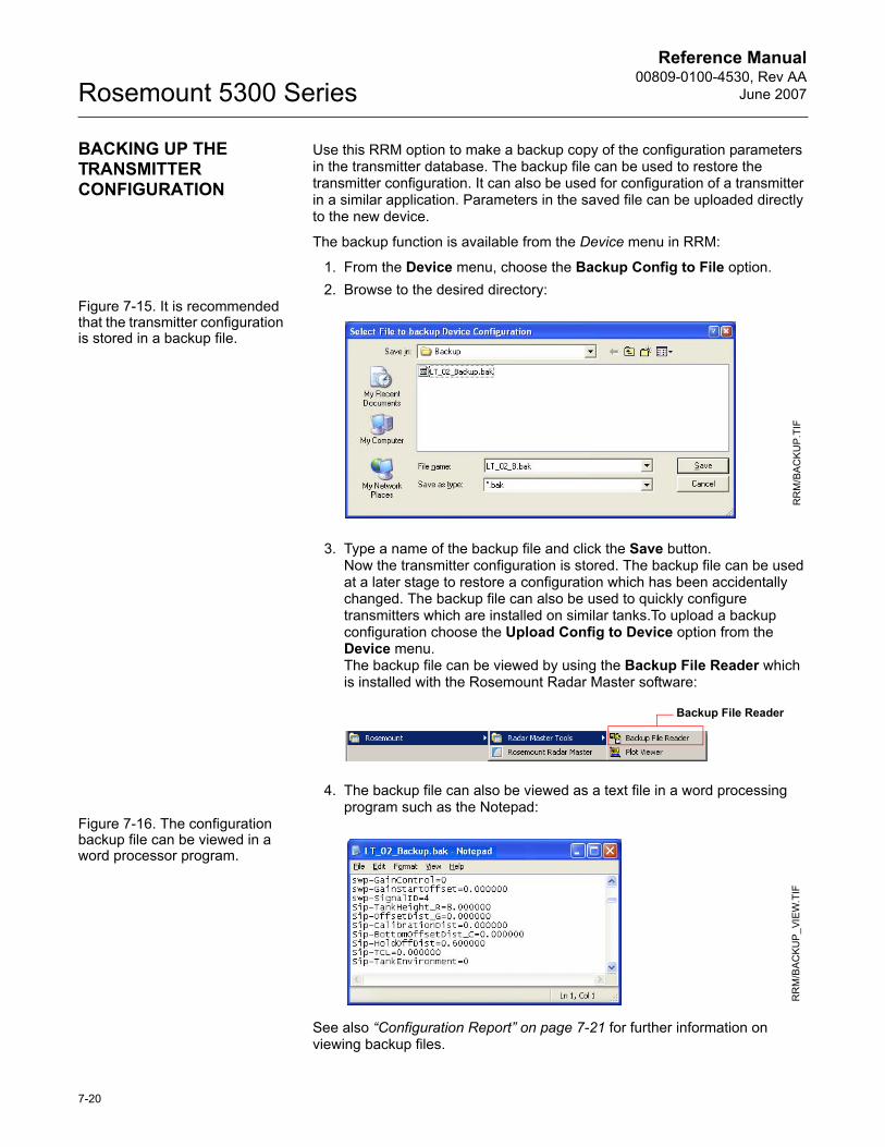
Reference Manual00809-0100-4530, Rev AA
June 2007Rosemount 5300 Series
BACKING UP THE TRANSMITTER CONFIGURATION
Use this RRM option to make a backup copy of the configuration parameters in the transmitter database. The backup file can be used to restore the transmitter configuration. It can also be used for configuration of a transmitter in a similar application. Parameters in the saved file can be uploaded directly to the new device.
The backup function is available from the Device menu in RRM:
1. From the Device menu, choose the Backup Config to File option.2. Browse to the desired directory:
Figure 7-15. It is recommended that the transmitter configuration is stored in a backup file.
3. Type a name of the backup file and click the Save button.Now the transmitter configuration is stored. The backup file can be used at a later stage to restore a configuration which has been accidentally changed. The backup file can also be used to quickly configure transmitters which are installed on similar tanks.To upload a backup configuration choose the Upload Config to Device option from the Device menu.The backup file can be viewed by using the Backup File Reader which is installed with the Rosemount Radar Master software:
4. The backup file can also be viewed as a text file in a word processing program such as the Notepad:
Figure 7-16. The configuration backup file can be viewed in a word processor program.
See also �Configuration Report� on page 7-21 for further information on viewing backup files.
RR
M/B
AC
KU
P.T
IF
Backup File Reader
RR
M/B
ACKU
P_V
IEW
.TIF
7-20
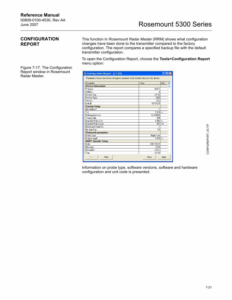
Reference Manual 00809-0100-4530, Rev AAJune 2007 Rosemount 5300 Series
CONFIGURATION REPORT
This function in Rosemount Radar Master (RRM) shows what configuration changes have been done to the transmitter compared to the factory configuration. The report compares a specified backup file with the default transmitter configuration.
To open the Configuration Report, choose the Tools>Configuration Report menu option:
Figure 7-17. The Configuration Report window in Rosemount Radar Master.
Information on probe type, software versions, software and hardware configuration and unit code is presented.
CO
NFI
GR
EP
OR
T_53
.TIF
7-21
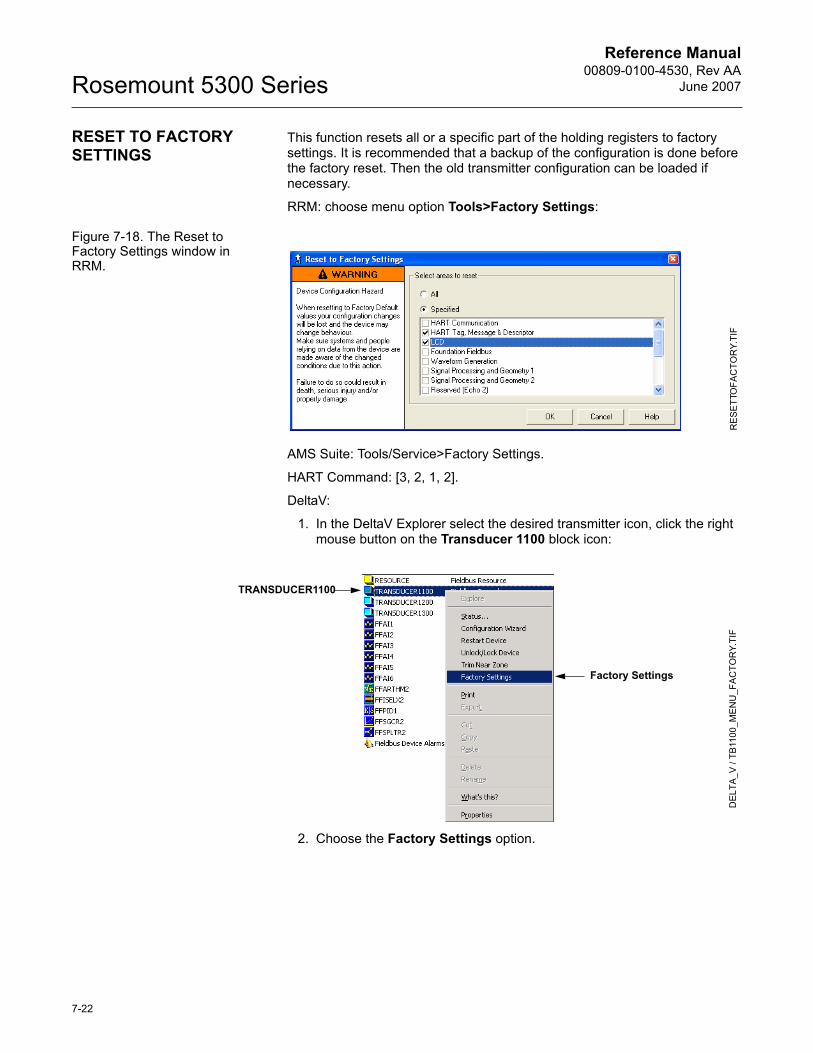
Reference Manual00809-0100-4530, Rev AA
June 2007Rosemount 5300 Series
RESET TO FACTORY SETTINGS
This function resets all or a specific part of the holding registers to factory settings. It is recommended that a backup of the configuration is done before the factory reset. Then the old transmitter configuration can be loaded if necessary.
RRM: choose menu option Tools>Factory Settings:
Figure 7-18. The Reset to Factory Settings window in RRM.
AMS Suite: Tools/Service>Factory Settings.
HART Command: [3, 2, 1, 2].
DeltaV:
1. In the DeltaV Explorer select the desired transmitter icon, click the right mouse button on the Transducer 1100 block icon:
2. Choose the Factory Settings option.
RES
ETT
OFA
CTO
RY.
TIF
Factory Settings
DEL
TA_V
/ TB
1100
_ME
NU
_FA
CTO
RY.
TIF
TRANSDUCER1100
7-22
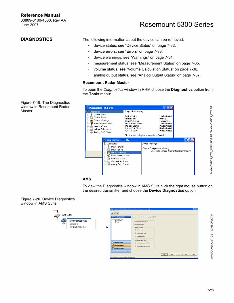
Reference Manual 00809-0100-4530, Rev AAJune 2007 Rosemount 5300 Series
DIAGNOSTICS The following information about the device can be retrieved:� device status, see �Device Status� on page 7-32.� device errors, see �Errors� on page 7-33.� device warnings, see �Warnings� on page 7-34.� measurement status, see �Measurement Status� on page 7-35.� volume status, see �Volume Calculation Status� on page 7-36.� analog output status, see �Analog Output Status� on page 7-37.
Rosemount Radar Master
To open the Diagnostics window in RRM choose the Diagnostics option from the Tools menu:
Figure 7-19. The Diagnostics window in Rosemount Radar Master.
AMS
To view the Diagnostics window in AMS Suite click the right mouse button on the desired transmitter and choose the Device Diagnostics option:
Figure 7-20. Device Diagnostics window in AMS Suite.
DIA
GN
OS
TIC
S_L
T02_
WAR
NIN
GS.
TIF
/ DIA
GN
OST
ICS
_LT0
2.TI
FA
MS
/DIA
GN
OST
ICS
_AD
VIS
OR
Y.TI
F
7-23
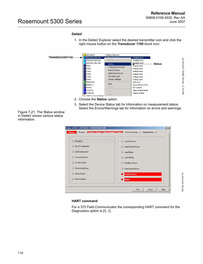
Reference Manual00809-0100-4530, Rev AA
June 2007Rosemount 5300 Series
DeltaV
1. In the DeltaV Explorer select the desired transmitter icon and click the right mouse button on the Transducer 1100 block icon:
2. Choose the Status option.3. Select the Device Status tab for information on measurement status.
Select the Errors/Warnings tab for information on errors and warnings.Figure 7-21. The Status window in DeltaV shows various status information.
HART command
For a 375 Field Communicator the corresponding HART command for the Diagnostics option is [3, 1].
Status
DEL
TA_V
/ TB
1100
_ME
NU
_STA
TUS
.TIFTRANSDUCER1100
TB11
00_S
TATU
S.T
IF
7-24
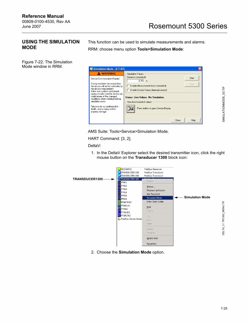
Reference Manual 00809-0100-4530, Rev AAJune 2007 Rosemount 5300 Series
USING THE SIMULATION MODE
This function can be used to simulate measurements and alarms.
RRM: choose menu option Tools>Simulation Mode:
Figure 7-22. The Simulation Mode window in RRM.
AMS Suite: Tools>Service>Simulation Mode.
HART Command: [3, 2].
DeltaV:
1. In the DeltaV Explorer select the desired transmitter icon, click the right mouse button on the Transducer 1300 block icon:
2. Choose the Simulation Mode option.
SIM
ULA
TIO
NM
OD
E_53
.TIF
Simulation Mode
DEL
TA_V
/ TR
1300
_ME
NU
.TIF
TRANSDUCER1300
7-25
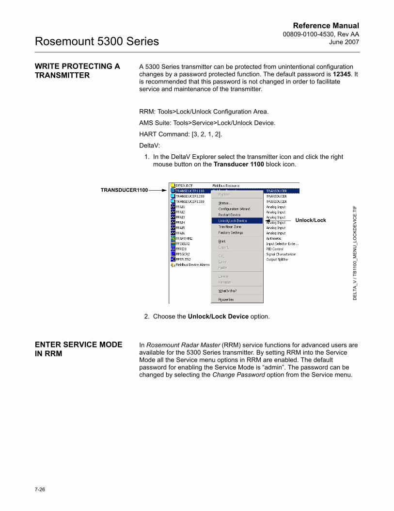
Reference Manual00809-0100-4530, Rev AA
June 2007Rosemount 5300 Series
WRITE PROTECTING A TRANSMITTER
A 5300 Series transmitter can be protected from unintentional configuration changes by a password protected function. The default password is 12345. It is recommended that this password is not changed in order to facilitate service and maintenance of the transmitter.
RRM: Tools>Lock/Unlock Configuration Area.
AMS Suite: Tools>Service>Lock/Unlock Device.
HART Command: [3, 2, 1, 2].
DeltaV:
1. In the DeltaV Explorer select the transmitter icon and click the right mouse button on the Transducer 1100 block icon.
2. Choose the Unlock/Lock Device option.
ENTER SERVICE MODE IN RRM
In Rosemount Radar Master (RRM) service functions for advanced users are available for the 5300 Series transmitter. By setting RRM into the Service Mode all the Service menu options in RRM are enabled. The default password for enabling the Service Mode is �admin�. The password can be changed by selecting the Change Password option from the Service menu.
Unlock/Lock
DE
LTA
_V /
TB11
00_M
ENU
_LO
CK
DEV
ICE.
TIF
TRANSDUCER1100
7-26
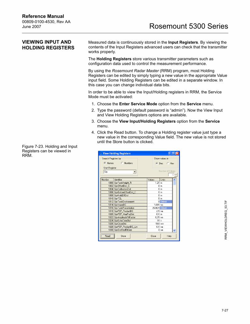
Reference Manual 00809-0100-4530, Rev AAJune 2007 Rosemount 5300 Series
VIEWING INPUT AND HOLDING REGISTERS
Measured data is continuously stored in the Input Registers. By viewing the contents of the Input Registers advanced users can check that the transmitter works properly.
The Holding Registers store various transmitter parameters such as configuration data used to control the measurement performance.
By using the Rosemount Radar Master (RRM) program, most Holding Registers can be edited by simply typing a new value in the appropriate Value input field. Some Holding Registers can be edited in a separate window. In this case you can change individual data bits.
In order to be able to view the Input/Holding registers in RRM, the Service Mode must be activated:
1. Choose the Enter Service Mode option from the Service menu.2. Type the password (default password is �admin�). Now the View Input
and View Holding Registers options are available.3. Choose the View Input/Holding Registers option from the Service
menu.4. Click the Read button. To change a Holding register value just type a
new value in the corresponding Value field. The new value is not stored until the Store button is clicked.
Figure 7-23. Holding and Input Registers can be viewed in RRM.
RR
M_V
IEW
HO
LDR
EG
_53.
TIF
7-27
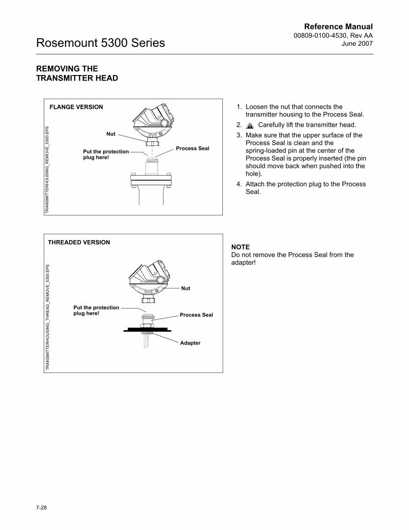
Reference Manual00809-0100-4530, Rev AA
June 2007Rosemount 5300 Series
REMOVING THE TRANSMITTER HEAD
1. Loosen the nut that connects the transmitter housing to the Process Seal.
2. Carefully lift the transmitter head.3. Make sure that the upper surface of the
Process Seal is clean and the spring-loaded pin at the center of the Process Seal is properly inserted (the pin should move back when pushed into the hole).
4. Attach the protection plug to the Process Seal.
Nut
Process SealPut the protection plug here!
FLANGE VERSION
TRA
NS
MIT
TER
HO
US
ING
_RE
MO
VE_
5300
.EPS
NOTEDo not remove the Process Seal from the adapter!
Nut
Process Seal
Adapter
THREADED VERSION
TRA
NS
MIT
TER
HO
USI
NG
_TH
RE
AD_R
EM
OV
E_53
00.E
PS
Put the protection plug here!
7-28
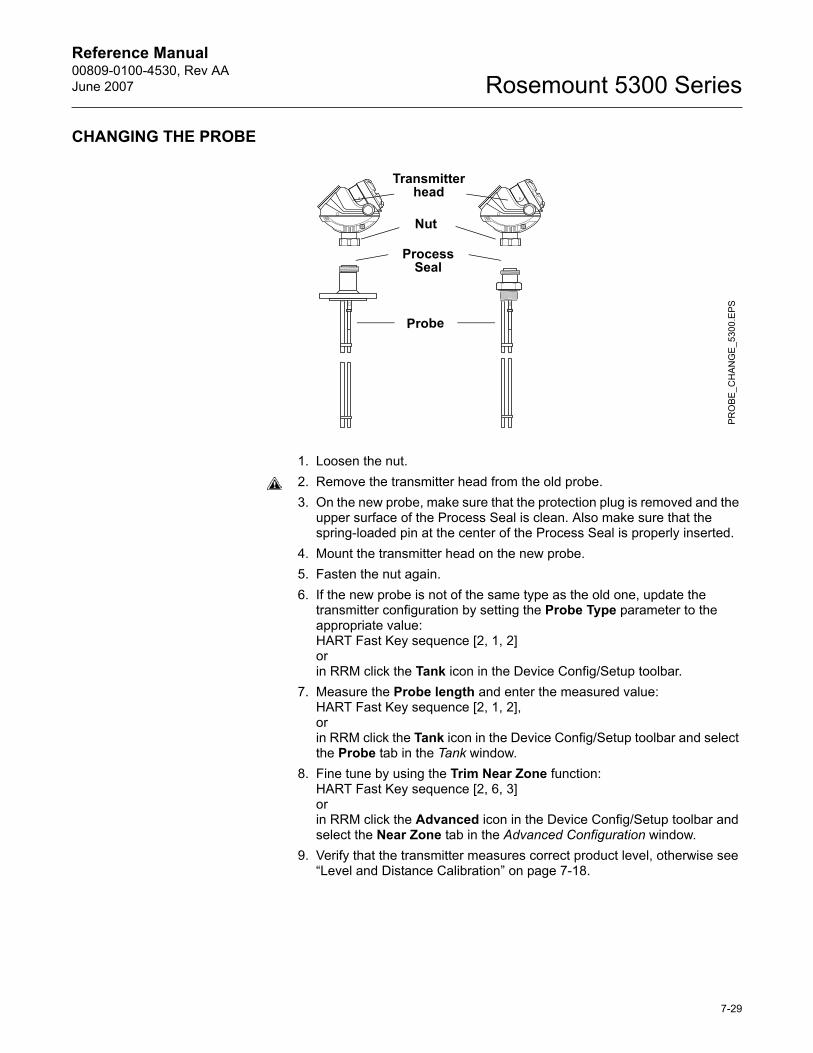
Reference Manual 00809-0100-4530, Rev AAJune 2007 Rosemount 5300 Series
CHANGING THE PROBE
1. Loosen the nut.2. Remove the transmitter head from the old probe.3. On the new probe, make sure that the protection plug is removed and the
upper surface of the Process Seal is clean. Also make sure that the spring-loaded pin at the center of the Process Seal is properly inserted.
4. Mount the transmitter head on the new probe.5. Fasten the nut again.6. If the new probe is not of the same type as the old one, update the
transmitter configuration by setting the Probe Type parameter to the appropriate value: HART Fast Key sequence [2, 1, 2]orin RRM click the Tank icon in the Device Config/Setup toolbar.
7. Measure the Probe length and enter the measured value:HART Fast Key sequence [2, 1, 2],orin RRM click the Tank icon in the Device Config/Setup toolbar and select the Probe tab in the Tank window.
8. Fine tune by using the Trim Near Zone function:HART Fast Key sequence [2, 6, 3]orin RRM click the Advanced icon in the Device Config/Setup toolbar and select the Near Zone tab in the Advanced Configuration window.
9. Verify that the transmitter measures correct product level, otherwise see �Level and Distance Calibration� on page 7-18.
Nut
Probe
Transmitter head
PR
OBE
_CH
AN
GE
_530
0.E
PS
Process Seal
7-29
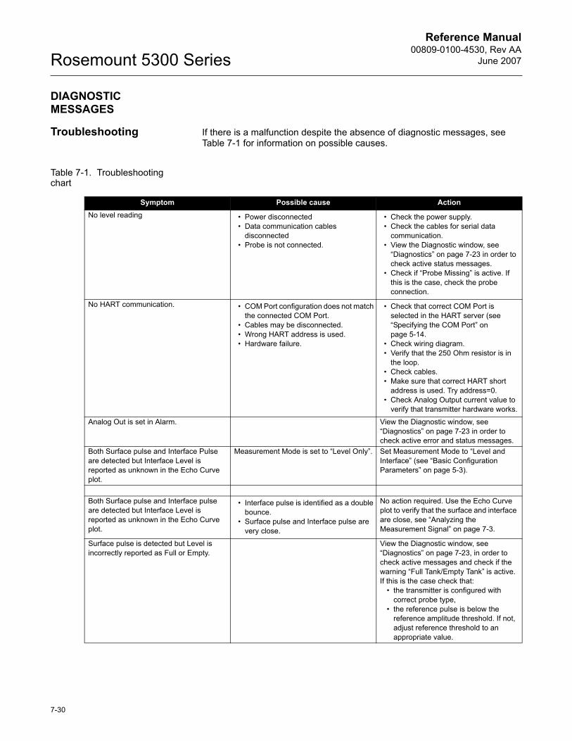
Reference Manual00809-0100-4530, Rev AA
June 2007Rosemount 5300 Series
DIAGNOSTIC MESSAGES
Troubleshooting If there is a malfunction despite the absence of diagnostic messages, see Table 7-1 for information on possible causes.
Table 7-1. Troubleshooting chart
Symptom Possible cause ActionNo level reading � Power disconnected
� Data communication cables disconnected
� Probe is not connected.
� Check the power supply.� Check the cables for serial data
communication.� View the Diagnostic window, see
�Diagnostics� on page 7-23 in order to check active status messages.
� Check if �Probe Missing� is active. If this is the case, check the probe connection.
No HART communication. � COM Port configuration does not match the connected COM Port.
� Cables may be disconnected.� Wrong HART address is used.� Hardware failure.
� Check that correct COM Port is selected in the HART server (see �Specifying the COM Port� on page 5-14.
� Check wiring diagram.� Verify that the 250 Ohm resistor is in
the loop.� Check cables.� Make sure that correct HART short
address is used. Try address=0.� Check Analog Output current value to
verify that transmitter hardware works.
Analog Out is set in Alarm. View the Diagnostic window, see �Diagnostics� on page 7-23 in order to check active error and status messages.
Both Surface pulse and Interface Pulse are detected but Interface Level is reported as unknown in the Echo Curve plot.
Measurement Mode is set to �Level Only�. Set Measurement Mode to �Level and Interface� (see �Basic Configuration Parameters� on page 5-3).
Both Surface pulse and Interface pulse are detected but Interface Level is reported as unknown in the Echo Curve plot.
� Interface pulse is identified as a double bounce.
� Surface pulse and Interface pulse are very close.
No action required. Use the Echo Curve plot to verify that the surface and interface are close, see �Analyzing the Measurement Signal� on page 7-3.
Surface pulse is detected but Level is incorrectly reported as Full or Empty.
View the Diagnostic window, see �Diagnostics� on page 7-23, in order to check active messages and check if the warning �Full Tank/Empty Tank� is active. If this is the case check that:
� the transmitter is configured with correct probe type,
� the reference pulse is below the reference amplitude threshold. If not, adjust reference threshold to an appropriate value.
7-30
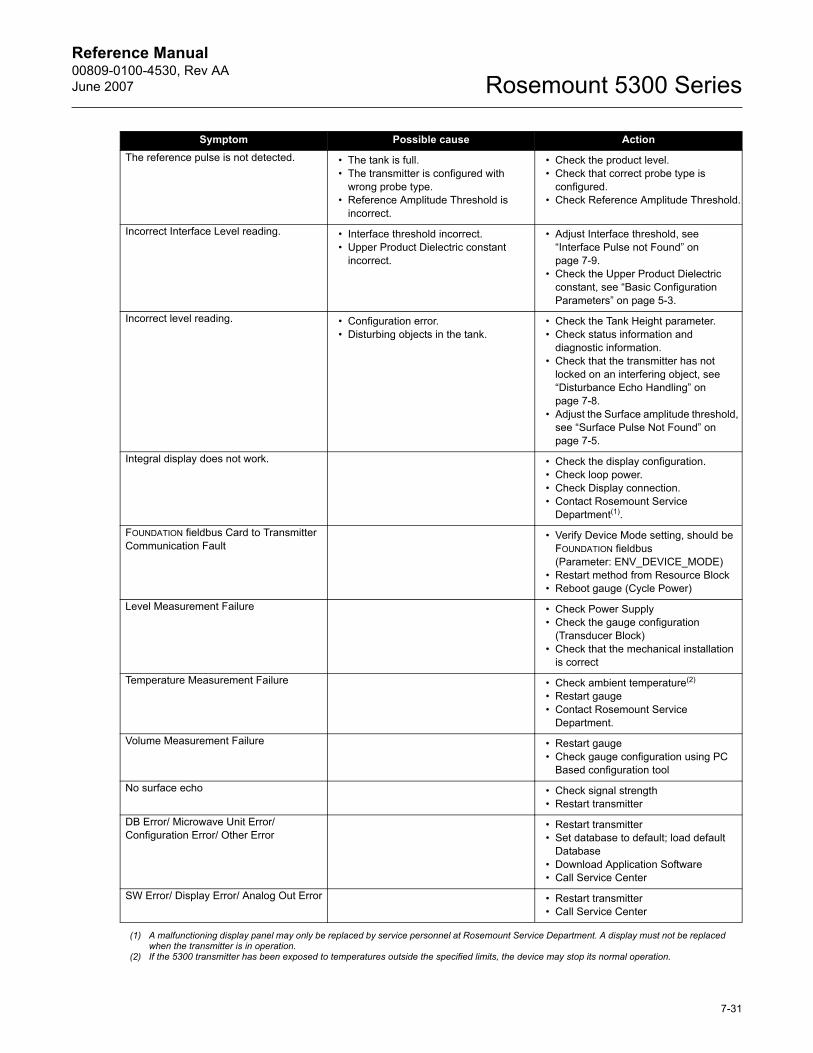
Reference Manual 00809-0100-4530, Rev AAJune 2007 Rosemount 5300 Series
The reference pulse is not detected. � The tank is full.� The transmitter is configured with
wrong probe type.� Reference Amplitude Threshold is
incorrect.
� Check the product level.� Check that correct probe type is
configured.� Check Reference Amplitude Threshold.
Incorrect Interface Level reading. � Interface threshold incorrect.� Upper Product Dielectric constant
incorrect.
� Adjust Interface threshold, see �Interface Pulse not Found� on page 7-9.
� Check the Upper Product Dielectric constant, see �Basic Configuration Parameters� on page 5-3.
Incorrect level reading. � Configuration error.� Disturbing objects in the tank.
� Check the Tank Height parameter.� Check status information and
diagnostic information.� Check that the transmitter has not
locked on an interfering object, see �Disturbance Echo Handling� on page 7-8.
� Adjust the Surface amplitude threshold, see �Surface Pulse Not Found� on page 7-5.
Integral display does not work. � Check the display configuration.� Check loop power.� Check Display connection.� Contact Rosemount Service
Department(1).
FOUNDATION fieldbus Card to Transmitter Communication Fault
� Verify Device Mode setting, should be FOUNDATION fieldbus (Parameter: ENV_DEVICE_MODE)
� Restart method from Resource Block� Reboot gauge (Cycle Power)
Level Measurement Failure � Check Power Supply� Check the gauge configuration
(Transducer Block)� Check that the mechanical installation
is correct
Temperature Measurement Failure � Check ambient temperature(2)
� Restart gauge� Contact Rosemount Service
Department.
Volume Measurement Failure � Restart gauge� Check gauge configuration using PC
Based configuration tool
No surface echo � Check signal strength� Restart transmitter
DB Error/ Microwave Unit Error/ Configuration Error/ Other Error
� Restart transmitter� Set database to default; load default
Database � Download Application Software� Call Service Center
SW Error/ Display Error/ Analog Out Error � Restart transmitter� Call Service Center
(1) A malfunctioning display panel may only be replaced by service personnel at Rosemount Service Department. A display must not be replaced when the transmitter is in operation.
(2) If the 5300 transmitter has been exposed to temperatures outside the specified limits, the device may stop its normal operation.
Symptom Possible cause Action
7-31
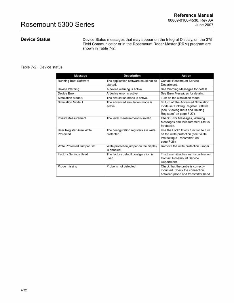
Reference Manual00809-0100-4530, Rev AA
June 2007Rosemount 5300 Series
Device Status Device Status messages that may appear on the Integral Display, on the 375 Field Communicator or in the Rosemount Radar Master (RRM) program are shown in Table 7-2:
Table 7-2. Device status.
Message Description ActionRunning Boot Software The application software could not be
started.Contact Rosemount Service Department.
Device Warning A device warning is active. See Warning Messages for details.Device Error A device error is active. See Error Messages for details.Simulation Mode 0 The simulation mode is active. Turn off the simulation mode.Simulation Mode 1 The advanced simulation mode is
active.To turn off the Advanced Simulation mode set Holding Register 3600=0 (see �Viewing Input and Holding Registers� on page 7-27).
Invalid Measurement The level measurement is invalid. Check Error Messages, Warning Messages and Measurement Status for details.
User Register Area Write Protected
The configuration registers are write protected.
Use the Lock/Unlock function to turn off the write protection (see �Write Protecting a Transmitter� on page 7-26).
Write Protected Jumper Set Write protection jumper on the display is enabled.
Remove the write protection jumper.
Factory Settings Used The factory default configuration is used.
The transmitter has lost its calibration. Contact Rosemount Service Department.
Probe missing Probe is not detected. Check that the probe is correctly mounted. Check the connection between probe and transmitter head.
7-32
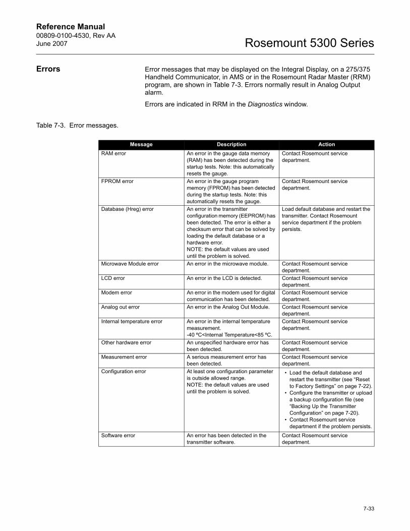
Reference Manual 00809-0100-4530, Rev AAJune 2007 Rosemount 5300 Series
Errors Error messages that may be displayed on the Integral Display, on a 275/375 Handheld Communicator, in AMS or in the Rosemount Radar Master (RRM) program, are shown in Table 7-3. Errors normally result in Analog Output alarm.
Errors are indicated in RRM in the Diagnostics window.
Table 7-3. Error messages.
Message Description ActionRAM error An error in the gauge data memory
(RAM) has been detected during the startup tests. Note: this automatically resets the gauge.
Contact Rosemount service department.
FPROM error An error in the gauge program memory (FPROM) has been detected during the startup tests. Note: this automatically resets the gauge.
Contact Rosemount service department.
Database (Hreg) error An error in the transmitter configuration memory (EEPROM) has been detected. The error is either a checksum error that can be solved by loading the default database or a hardware error.NOTE: the default values are used until the problem is solved.
Load default database and restart the transmitter. Contact Rosemount service department if the problem persists.
Microwave Module error An error in the microwave module. Contact Rosemount service department.
LCD error An error in the LCD is detected. Contact Rosemount service department.
Modem error An error in the modem used for digital communication has been detected.
Contact Rosemount service department.
Analog out error An error in the Analog Out Module. Contact Rosemount service department.
Internal temperature error An error in the internal temperature measurement. -40 ºC<Internal Temperature<85 ºC.
Contact Rosemount service department.
Other hardware error An unspecified hardware error has been detected.
Contact Rosemount service department.
Measurement error A serious measurement error has been detected.
Contact Rosemount service department.
Configuration error At least one configuration parameter is outside allowed range. NOTE: the default values are used until the problem is solved.
� Load the default database and restart the transmitter (see �Reset to Factory Settings� on page 7-22).
� Configure the transmitter or upload a backup configuration file (see �Backing Up the Transmitter Configuration� on page 7-20).
� Contact Rosemount service department if the problem persists.
Software error An error has been detected in the transmitter software.
Contact Rosemount service department.
7-33
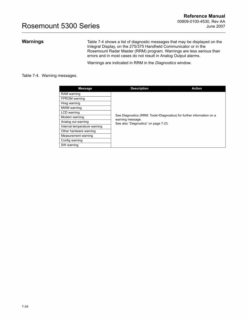
Reference Manual00809-0100-4530, Rev AA
June 2007Rosemount 5300 Series
Warnings Table 7-4 shows a list of diagnostic messages that may be displayed on the Integral Display, on the 275/375 Handheld Communicator or in the Rosemount Radar Master (RRM) program. Warnings are less serious than errors and in most cases do not result in Analog Output alarms.
Warnings are indicated in RRM in the Diagnostics window.
Table 7-4. Warning messages.
Message Description ActionRAM warning
See Diagnostics (RRM: Tools>Diagnostics) for further information on a warning message. See also �Diagnostics� on page 7-23.
FPROM warningHreg warningMWM warningLCD warningModem warningAnalog out warningInternal temperature warningOther hardware warningMeasurement warningConfig warningSW warning
7-34
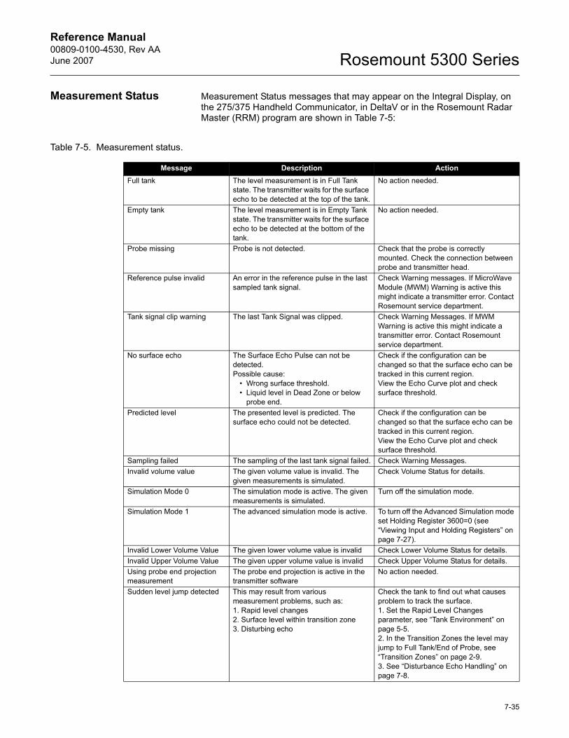
Reference Manual 00809-0100-4530, Rev AAJune 2007 Rosemount 5300 Series
Measurement Status Measurement Status messages that may appear on the Integral Display, on the 275/375 Handheld Communicator, in DeltaV or in the Rosemount Radar Master (RRM) program are shown in Table 7-5:
Table 7-5. Measurement status.
Message Description ActionFull tank The level measurement is in Full Tank
state. The transmitter waits for the surface echo to be detected at the top of the tank.
No action needed.
Empty tank The level measurement is in Empty Tank state. The transmitter waits for the surface echo to be detected at the bottom of the tank.
No action needed.
Probe missing Probe is not detected. Check that the probe is correctly mounted. Check the connection between probe and transmitter head.
Reference pulse invalid An error in the reference pulse in the last sampled tank signal.
Check Warning messages. If MicroWave Module (MWM) Warning is active this might indicate a transmitter error. Contact Rosemount service department.
Tank signal clip warning The last Tank Signal was clipped. Check Warning Messages. If MWM Warning is active this might indicate a transmitter error. Contact Rosemount service department.
No surface echo The Surface Echo Pulse can not be detected.Possible cause:
� Wrong surface threshold.� Liquid level in Dead Zone or below
probe end.
Check if the configuration can be changed so that the surface echo can be tracked in this current region.View the Echo Curve plot and check surface threshold.
Predicted level The presented level is predicted. The surface echo could not be detected.
Check if the configuration can be changed so that the surface echo can be tracked in this current region.View the Echo Curve plot and check surface threshold.
Sampling failed The sampling of the last tank signal failed. Check Warning Messages.Invalid volume value The given volume value is invalid. The
given measurements is simulated.Check Volume Status for details.
Simulation Mode 0 The simulation mode is active. The given measurements is simulated.
Turn off the simulation mode.
Simulation Mode 1 The advanced simulation mode is active. To turn off the Advanced Simulation mode set Holding Register 3600=0 (see �Viewing Input and Holding Registers� on page 7-27).
Invalid Lower Volume Value The given lower volume value is invalid Check Lower Volume Status for details.Invalid Upper Volume Value The given upper volume value is invalid Check Upper Volume Status for details.Using probe end projection measurement
The probe end projection is active in the transmitter software
No action needed.
Sudden level jump detected This may result from various measurement problems, such as:1. Rapid level changes2. Surface level within transition zone3. Disturbing echo
Check the tank to find out what causes problem to track the surface.1. Set the Rapid Level Changes parameter, see �Tank Environment� on page 5-5.2. In the Transition Zones the level may jump to Full Tank/End of Probe, see �Transition Zones� on page 2-9.3. See �Disturbance Echo Handling� on page 7-8.
7-35
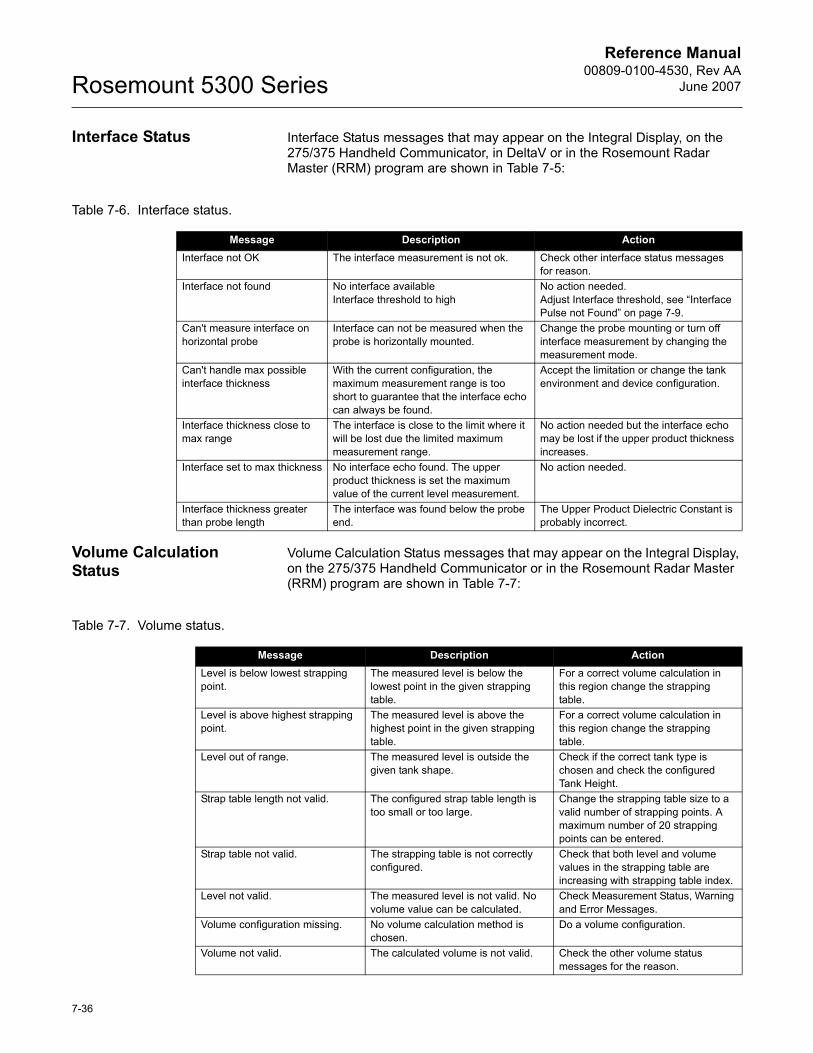
Reference Manual00809-0100-4530, Rev AA
June 2007Rosemount 5300 Series
Interface Status Interface Status messages that may appear on the Integral Display, on the 275/375 Handheld Communicator, in DeltaV or in the Rosemount Radar Master (RRM) program are shown in Table 7-5:
Table 7-6. Interface status.
Volume Calculation Status
Volume Calculation Status messages that may appear on the Integral Display, on the 275/375 Handheld Communicator or in the Rosemount Radar Master (RRM) program are shown in Table 7-7:
Table 7-7. Volume status.
Message Description ActionInterface not OK The interface measurement is not ok. Check other interface status messages
for reason.Interface not found No interface available
Interface threshold to highNo action needed.Adjust Interface threshold, see �Interface Pulse not Found� on page 7-9.
Can't measure interface on horizontal probe
Interface can not be measured when the probe is horizontally mounted.
Change the probe mounting or turn off interface measurement by changing the measurement mode.
Can't handle max possible interface thickness
With the current configuration, the maximum measurement range is too short to guarantee that the interface echo can always be found.
Accept the limitation or change the tank environment and device configuration.
Interface thickness close to max range
The interface is close to the limit where it will be lost due the limited maximum measurement range.
No action needed but the interface echo may be lost if the upper product thickness increases.
Interface set to max thickness No interface echo found. The upper product thickness is set the maximum value of the current level measurement.
No action needed.
Interface thickness greater than probe length
The interface was found below the probe end.
The Upper Product Dielectric Constant is probably incorrect.
Message Description ActionLevel is below lowest strapping point.
The measured level is below the lowest point in the given strapping table.
For a correct volume calculation in this region change the strapping table.
Level is above highest strapping point.
The measured level is above the highest point in the given strapping table.
For a correct volume calculation in this region change the strapping table.
Level out of range. The measured level is outside the given tank shape.
Check if the correct tank type is chosen and check the configured Tank Height.
Strap table length not valid. The configured strap table length is too small or too large.
Change the strapping table size to a valid number of strapping points. A maximum number of 20 strapping points can be entered.
Strap table not valid. The strapping table is not correctly configured.
Check that both level and volume values in the strapping table are increasing with strapping table index.
Level not valid. The measured level is not valid. No volume value can be calculated.
Check Measurement Status, Warning and Error Messages.
Volume configuration missing. No volume calculation method is chosen.
Do a volume configuration.
Volume not valid. The calculated volume is not valid. Check the other volume status messages for the reason.
7-36
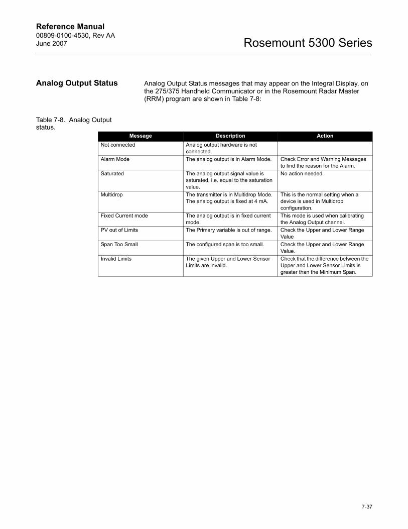
Reference Manual 00809-0100-4530, Rev AAJune 2007 Rosemount 5300 Series
Analog Output Status Analog Output Status messages that may appear on the Integral Display, on the 275/375 Handheld Communicator or in the Rosemount Radar Master (RRM) program are shown in Table 7-8:
Table 7-8. Analog Output status.
Message Description ActionNot connected Analog output hardware is not
connected.Alarm Mode The analog output is in Alarm Mode. Check Error and Warning Messages
to find the reason for the Alarm.Saturated The analog output signal value is
saturated, i.e. equal to the saturation value.
No action needed.
Multidrop The transmitter is in Multidrop Mode. The analog output is fixed at 4 mA.
This is the normal setting when a device is used in Multidrop configuration.
Fixed Current mode The analog output is in fixed current mode.
This mode is used when calibrating the Analog Output channel.
PV out of Limits The Primary variable is out of range. Check the Upper and Lower Range Value
Span Too Small The configured span is too small. Check the Upper and Lower Range Value.
Invalid Limits The given Upper and Lower Sensor Limits are invalid.
Check that the difference between the Upper and Lower Sensor Limits is greater than the Minimum Span.
7-37
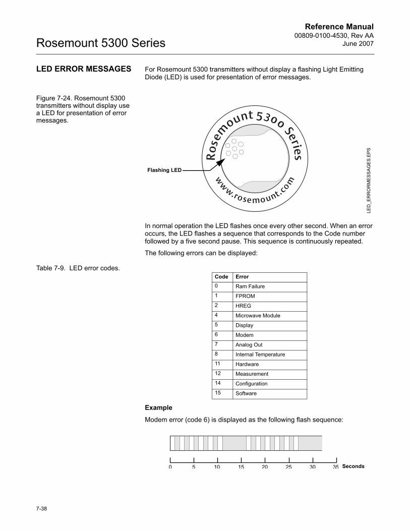
Reference Manual00809-0100-4530, Rev AA
June 2007Rosemount 5300 Series
LED ERROR MESSAGES For Rosemount 5300 transmitters without display a flashing Light Emitting Diode (LED) is used for presentation of error messages.
Figure 7-24. Rosemount 5300 transmitters without display use a LED for presentation of error messages.
In normal operation the LED flashes once every other second. When an error occurs, the LED flashes a sequence that corresponds to the Code number followed by a five second pause. This sequence is continuously repeated.
The following errors can be displayed:
Table 7-9. LED error codes.
Example
Modem error (code 6) is displayed as the following flash sequence:
LED
_ER
RO
RM
ES
SAG
ES.
EPS
Flashing LED
Code Error0 Ram Failure
1 FPROM
2 HREG
4 Microwave Module
5 Display
6 Modem
7 Analog Out
8 Internal Temperature
11 Hardware
12 Measurement
14 Configuration
15 Software
Seconds
7-38
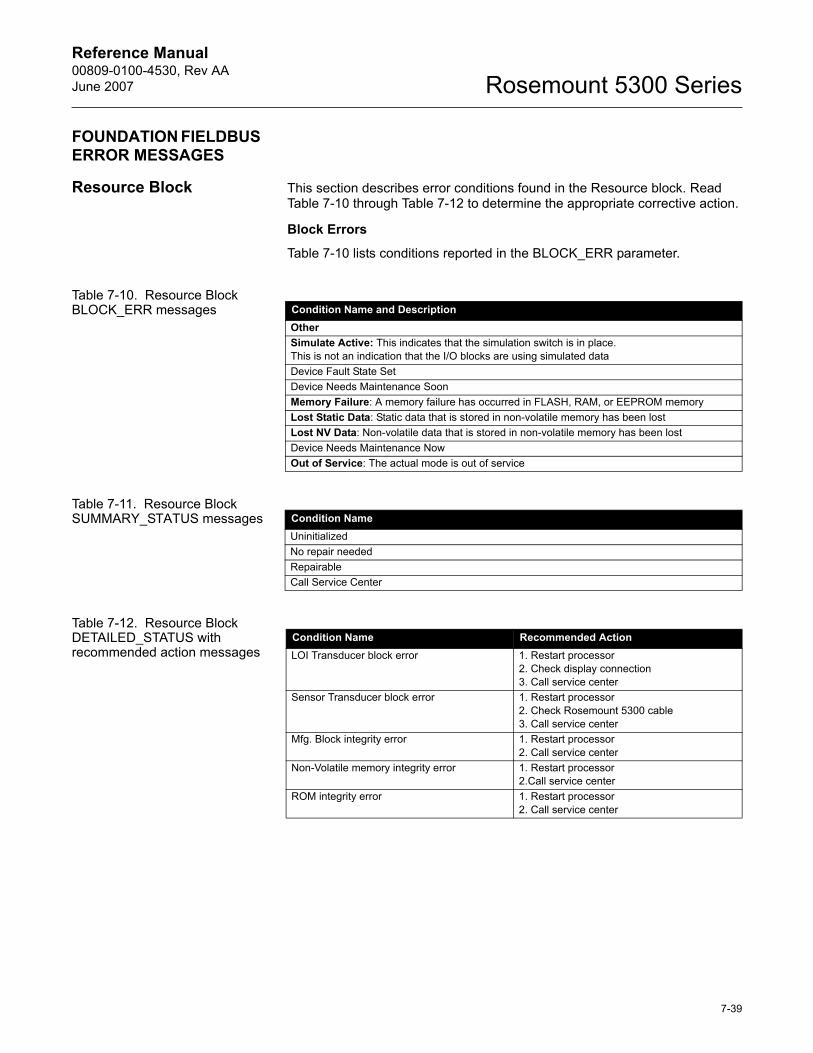
Reference Manual 00809-0100-4530, Rev AAJune 2007 Rosemount 5300 Series
FOUNDATION FIELDBUS ERROR MESSAGES
Resource Block This section describes error conditions found in the Resource block. Read Table 7-10 through Table 7-12 to determine the appropriate corrective action.
Block Errors
Table 7-10 lists conditions reported in the BLOCK_ERR parameter.
Table 7-10. Resource Block BLOCK_ERR messages
Table 7-11. Resource Block SUMMARY_STATUS messages
Table 7-12. Resource Block DETAILED_STATUS with recommended action messages
Condition Name and DescriptionOtherSimulate Active: This indicates that the simulation switch is in place. This is not an indication that the I/O blocks are using simulated dataDevice Fault State SetDevice Needs Maintenance SoonMemory Failure: A memory failure has occurred in FLASH, RAM, or EEPROM memoryLost Static Data: Static data that is stored in non-volatile memory has been lostLost NV Data: Non-volatile data that is stored in non-volatile memory has been lostDevice Needs Maintenance NowOut of Service: The actual mode is out of service
Condition NameUninitializedNo repair neededRepairableCall Service Center
Condition Name Recommended ActionLOI Transducer block error 1. Restart processor
2. Check display connection3. Call service center
Sensor Transducer block error 1. Restart processor2. Check Rosemount 5300 cable3. Call service center
Mfg. Block integrity error 1. Restart processor2. Call service center
Non-Volatile memory integrity error 1. Restart processor2.Call service center
ROM integrity error 1. Restart processor2. Call service center
7-39
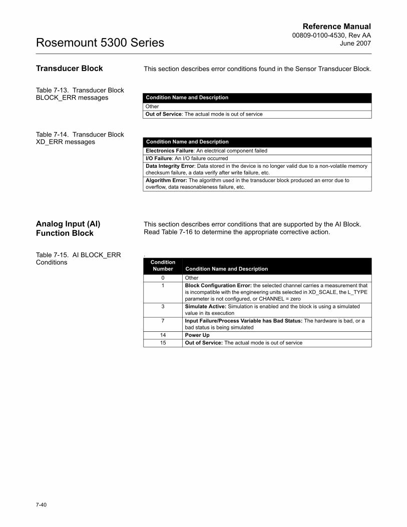
Reference Manual00809-0100-4530, Rev AA
June 2007Rosemount 5300 Series
Transducer Block This section describes error conditions found in the Sensor Transducer Block.
Table 7-13. Transducer Block BLOCK_ERR messages
Table 7-14. Transducer Block XD_ERR messages
Analog Input (AI) Function Block
This section describes error conditions that are supported by the AI Block. Read Table 7-16 to determine the appropriate corrective action.
Table 7-15. AI BLOCK_ERR Conditions
.
Condition Name and DescriptionOtherOut of Service: The actual mode is out of service
Condition Name and DescriptionElectronics Failure: An electrical component failedI/O Failure: An I/O failure occurredData Integrity Error: Data stored in the device is no longer valid due to a non-volatile memory checksum failure, a data verify after write failure, etc.Algorithm Error: The algorithm used in the transducer block produced an error due to overflow, data reasonableness failure, etc.
Condition Number Condition Name and Description
0 Other1 Block Configuration Error: the selected channel carries a measurement that
is incompatible with the engineering units selected in XD_SCALE, the L_TYPE parameter is not configured, or CHANNEL = zero
3 Simulate Active: Simulation is enabled and the block is using a simulated value in its execution
7 Input Failure/Process Variable has Bad Status: The hardware is bad, or a bad status is being simulated
14 Power Up15 Out of Service: The actual mode is out of service
7-40
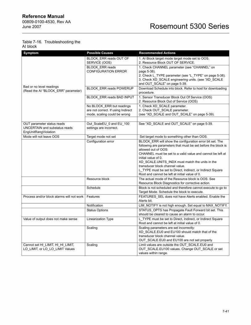
Reference Manual 00809-0100-4530, Rev AAJune 2007 Rosemount 5300 Series
Table 7-16. Troubleshooting the AI blockSymptom Possible Causes Recommended Actions
Bad or no level readings(Read the AI �BLOCK_ERR� parameter)
BLOCK_ERR reads OUT OF SERVICE (OOS)
1. AI Block target mode target mode set to OOS.2. Resource Block OUT OF SERVICE.
BLOCK_ERR reads CONFIGURATION ERROR
1. Check CHANNEL parameter (see �CHANNEL� on page 5-38).2. Check L_TYPE parameter (see �L_TYPE� on page 5-38).3. Check XD_SCALE engineering units. (see �XD_SCALE and OUT_SCALE� on page 5-39.
BLOCK_ERR reads POWERUP Download Schedule into block. Refer to host for downloading procedure.
BLOCK_ERR reads BAD INPUT 1. Sensor Transducer Block Out Of Service (OOS)2. Resource Block Out of Service (OOS)
No BLOCK_ERR but readings are not correct. If using Indirect mode, scaling could be wrong
1. Check XD_SCALE parameter.2. Check OUT_SCALE parameter. (see �XD_SCALE and OUT_SCALE� on page 5-39).
OUT parameter status reads UNCERTAIN and substatus reads EngUnitRangViolation
Out_ScaleEU_0 and EU_100 settings are incorrect.
See �XD_SCALE and OUT_SCALE� on page 5-39.
Mode will not leave OOS Target mode not set Set target mode to something other than OOS.Configuration error BLOCK_ERR will show the configuration error bit set. The
following are parameters that must be set before the block is allowed out of OOS:CHANNEL must be set to a valid value and cannot be left at initial value of 0.XD_SCALE.UNITS_INDX must match the units in the transducer block channel value.L_TYPE must be set to Direct, Indirect, or Indirect Square Root and cannot be left at initial value of 0.
Resource block The actual mode of the Resource block is OOS. See Resource Block Diagnostics for corrective action.
Schedule Block is not scheduled and therefore cannot execute to go to Target Mode. Schedule the block to execute.
Process and/or block alarms will not work Features FEATURES_SEL does not have Alerts enabled. Enable the Alerts bit.
Notification LIM_NOTIFY is not high enough. Set equal to MAX_NOTIFY.Status Options STATUS_OPTS has Propagate Fault Forward bit set. This
should be cleared to cause an alarm to occur.Value of output does not make sense Linearization Type L_TYPE must be set to Direct, Indirect, or Indirect Square
Root and cannot be left at initial value of 0.Scaling Scaling parameters are set incorrectly:
XD_SCALE.EU0 and EU100 should match that of the transducer block channel value.OUT_SCALE.EU0 and EU100 are not set properly.
Cannot set HI_LIMIT, HI_HI_LIMIT, LO_LIMIT, or LO_LO_LIMIT Values
Scaling Limit values are outside the OUT_SCALE.EU0 and OUT_SCALE.EU100 values. Change OUT_SCALE or set values within range.
7-41

Reference Manual00809-0100-4530, Rev AA
June 2007Rosemount 5300 Series
7-42
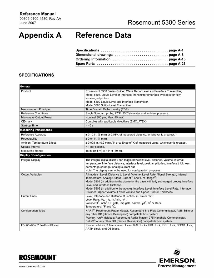
Reference Manual 00809-0100-4530, Rev AAJune 2007 Rosemount 5300 Series
Appendix A Reference Data
Specifications . . . . . . . . . . . . . . . . . . . . . . . . . . . . . . . . . . . page A-1Dimensional drawings . . . . . . . . . . . . . . . . . . . . . . . . . . . . page A-8Ordering Information . . . . . . . . . . . . . . . . . . . . . . . . . . . . . page A-16Spare Parts . . . . . . . . . . . . . . . . . . . . . . . . . . . . . . . . . . . . . page A-23
SPECIFICATIONS
GeneralProduct Rosemount 5300 Series Guided Wave Radar Level and Interface Transmitter;
Model 5301, Liquid Level or Interface Transmitter (interface available for fully submerged probe).Model 5302 Liquid Level and Interface Transmitter.Model 5303 Solids Level Transmitter.
Measurement Principle Time Domain Reflectometry (TDR).Reference Conditions Single Standard probe, 77°F (25°C) in water and ambient pressure.Microwave Output Power Nominal 300 µW, Max. 45 mW.CE-mark Complies with applicable directives (EMC, ATEX).Start-up Time < 40 s
Measuring Performance Reference Accuracy ± 0.12 in. (3 mm) or 0.03% of measured distance, whichever is greatest.(1)
Repeatability ± 0.04 in. (1 mm).Ambient Temperature Effect ± 0.008 in. (0.2 mm) /°K or ± 30 ppm/°K of measured value, whichever is greatest.Update Interval < 1 per second.Measuring Range 16 in. (0.4 m) to 164 ft (50 m).
Display / ConfigurationIntegral Display The integral digital display can toggle between: level, distance, volume, internal
temperature, interface distance, interface level, peak amplitudes, interface thickness, percentage of range, analog current out.Note! The display cannot be used for configuration purposes.
Output Variables All models: Level, Distance to Level, Volume, Level Rate, Signal Strength, Internal Temperature, Analog Output Current(2) and % of Range(2), Model 5301 (in addition to the above for the case with fully submerged probe): Interface Level and Interface Distance.Model 5302 (in addition to the above): Interface Level, Interface Level Rate, Interface Distance, Upper Volume, Lower Volume and Upper Product Thickness.
Output Units Level, Interface and Distance: ft, inches, m, cm or mm.Level Rate: ft/s, m/s, in./min, m/h.Volume: ft3, inch3, US gals, Imp gals, barrels, yd3, m3 or liters.Temperature: °F and °C.
Configuration Tools HART®: Rosemount Radar Master, Rosemount 375 Field Communicator, AMS Suite or any other DD (Device Description) compatible host system.FOUNDATION� fieldbus: Rosemount Radar Master, 375 Handheld Communicator, DeltaV® or any other DD (Device Description) compatible host system.
FOUNDATION� fieldbus Blocks Resource block, 3 Transducer blocks, 6 AI blocks, PID block, ISEL block, SGCR block, ARTH block, and OS block.
www.rosemount.com
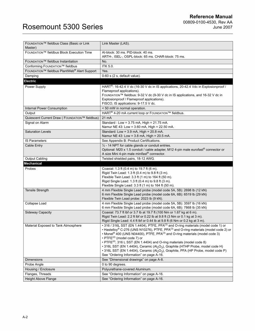
Reference Manual00809-0100-4530, Rev AA
June 2007Rosemount 5300 Series
FOUNDATION� fieldbus Class (Basic or Link Master)
Link Master (LAS).
FOUNDATION� fieldbus Block Execution Time AI-block: 30 ms. PID-block: 40 ms. ARTH-, ISEL-, OSPL-block: 65 ms. CHAR-block: 75 ms.
FOUNDATION� fieldbus Instantiation No.Conforming FOUNDATION� fieldbus ITK 5.0.FOUNDATION� fieldbus PlantWeb® Alert Support Yes.Damping 0-60 s (2 s, default value).
ElectricPower Supply HART®: 16-42.4 V dc (16-30 V dc in IS applications, 20-42.4 Vdc in Explosionproof /
Flameproof applications).FOUNDATION� fieldbus: 9-32 V dc (9-30 V dc in IS applications, and 16-32 V dc in Explosionproof / Flameproof applications). FISCO, IS applications: 9-17.5 V dc.
Internal Power Consumption < 50 mW in normal operation.Output HART® 4-20 mA current loop or FOUNDATION� fieldbus.Quiescent Current Draw ( FOUNDATION� fieldbus) 21 mASignal on Alarm Standard : Low = 3.75 mA, High = 21.75 mA.
Namur NE 43: Low = 3.60 mA, High = 22.50 mA.Saturation Levels Standard: Low = 3.9 mA, High = 20.8 mA.
Namur NE 43: Low = 3.8 mA, High = 20.5 mA.IS Parameters See Appendix B: Product Certifications.Cable Entry ½ - 14 NPT for cable glands or conduit entries.
Optional: M20 x 1.5 conduit / cable adapter, M12 4-pin male eurofast® connector or A size Mini 4-pin male minifast® connector.
Output Cabling Twisted shielded pairs, 18-12 AWG.MechanicalProbes Coaxial: 1.3 ft (0.4 m) to 19.7 ft (6 m).
Rigid Twin Lead: 1.3 ft (0.4 m) to 9.8 ft (3 m).Flexible Twin Lead: 3.3 ft (1 m) to 164 ft (50 m).Rigid Single Lead: 1.3 ft (0.4 m) to 9.8 ft (3 m).Flexible Single Lead: 3.3 ft (1 m) to 164 ft (50 m).
Tensile Strength 4 mm Flexible Single Lead probe (model code 5A, 5B): 2698 lb (12 kN) 6 mm Flexible Single Lead probe (model code 6A, 6B): 6519 lb (29 kN) Flexible Twin Lead probe: 2023 lb (9 kN).
Collapse Load 4 mm Flexible Single Lead probe (model code 5A, 5B): 3597 lb (16 kN) 6 mm Flexible Single Lead probe (model code 6A, 6B): 7868 lb (35 kN)
Sideway Capacity Coaxial: 73.7 ft lbf or 3.7 lb at 19.7 ft (100 Nm or 1.67 kg at 6 m).Rigid Twin Lead: 2.2 ft lbf or 0.22 lb at 9.8 ft (3 Nm or 0.1 kg at 3 m).Rigid Single Lead: 4.4 ft lbf or 0.44 lb at 9.8 ft (6 Nm or 0.2 kg at 3 m).
Material Exposed to Tank Atmosphere � 316 / 316L SST (EN 1.4404), PTFE, PFA(3) and O-ring materials (model code 1) or� Hastelloy® C-276 (UNS N10276), PTFE, PFA(3) and O-ring materials (model code 2) or� Monel® 400 (UNS N04400), PTFE, PFA(3) and O-ring materials (model code 3)� PTFE(4) (model code 7) or� PTFE(4), 316 L SST (EN 1.4404) and O-ring materials (model code 8)� 316L SST (EN 1.4404), Ceramic (Al2O3), Graphite (HTHP Probe, model code H)� 316L SST (EN 1.4404), Ceramic (Al2O3), Graphite, PFA (HP Probe, model code P)See �Ordering Information� on page A-16.
Dimensions See �Dimensional drawings� on page A-8.Probe Angle 0 to 90 degrees.Housing / Enclosure Polyurethane-covered Aluminum.Flanges, Threads See �Ordering Information� on page A-16.Height Above Flange See �Ordering Information� on page A-16.
A-2
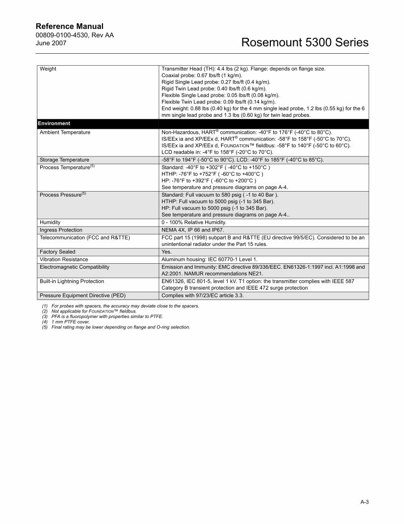
Reference Manual 00809-0100-4530, Rev AAJune 2007 Rosemount 5300 Series
Weight Transmitter Head (TH): 4.4 lbs (2 kg). Flange: depends on flange size.Coaxial probe: 0.67 lbs/ft (1 kg/m).Rigid Single Lead probe: 0.27 lbs/ft (0.4 kg/m).Rigid Twin Lead probe: 0.40 lbs/ft (0.6 kg/m).Flexible Single Lead probe: 0.05 lbs/ft (0.08 kg/m).Flexible Twin Lead probe: 0.09 lbs/ft (0.14 kg/m).End weight: 0.88 lbs (0.40 kg) for the 4 mm single lead probe, 1.2 lbs (0.55 kg) for the 6 mm single lead probe and 1.3 lbs (0.60 kg) for twin lead probes.
EnvironmentAmbient Temperature Non-Hazardous, HART® communication: -40°F to 176°F (-40°C to 80°C).
IS/EEx ia and XP/EEx d, HART® communication: -58°F to 158°F (-50°C to 70°C).IS/EEx ia and XP/EEx d, FOUNDATION� fieldbus: -58°F to 140°F (-50°C to 60°C).LCD readable in: -4°F to 158°F (-20°C to 70°C).
Storage Temperature -58°F to 194°F (-50°C to 90°C). LCD: -40°F to 185°F (-40°C to 85°C).Process Temperature(5) Standard: -40°F to +302°F ( -40°C to +150°C )
HTHP: -76°F to +752°F ( -60°C to +400°C )HP: -76°F to +392°F ( -60°C to +200°C )See temperature and pressure diagrams on page A-4.
Process Pressure(5) Standard: Full vacuum to 580 psig ( -1 to 40 Bar ).HTHP: Full vacuum to 5000 psig (-1 to 345 Bar).HP: Full vacuum to 5000 psig (-1 to 345 Bar).See temperature and pressure diagrams on page A-4..
Humidity 0 - 100% Relative Humidity.Ingress Protection NEMA 4X, IP 66 and IP67.Telecommunication (FCC and R&TTE) FCC part 15 (1998) subpart B and R&TTE (EU directive 99/5/EC). Considered to be an
unintentional radiator under the Part 15 rules.Factory Sealed Yes.Vibration Resistance Aluminum housing: IEC 60770-1 Level 1.Electromagnetic Compatibility Emission and Immunity: EMC directive 89/336/EEC. EN61326-1:1997 incl. A1:1998 and
A2:2001. NAMUR recommendations NE21.Built-in Lightning Protection EN61326, IEC 801-5, level 1 kV. T1 option: the transmitter complies with IEEE 587
Category B transient protection and IEEE 472 surge protectionPressure Equipment Directive (PED) Complies with 97/23/EC article 3.3.
(1) For probes with spacers, the accuracy may deviate close to the spacers.(2) Not applicable for FOUNDATION� fieldbus.(3) PFA is a fluoropolymer with properties similar to PTFE.(4) 1 mm PTFE cover.(5) Final rating may be lower depending on flange and O-ring selection.
A-3
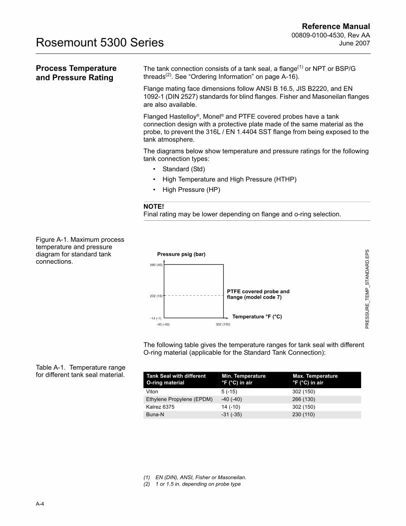
Reference Manual00809-0100-4530, Rev AA
June 2007Rosemount 5300 Series
Process Temperature and Pressure Rating
The tank connection consists of a tank seal, a flange(1) or NPT or BSP/G threads(2). See �Ordering Information� on page A-16).
Flange mating face dimensions follow ANSI B 16.5, JIS B2220, and EN 1092-1 (DIN 2527) standards for blind flanges. Fisher and Masoneilan flanges are also available.
Flanged Hastelloy®, Monel® and PTFE covered probes have a tank connection design with a protective plate made of the same material as the probe, to prevent the 316L / EN 1.4404 SST flange from being exposed to the tank atmosphere.
The diagrams below show temperature and pressure ratings for the following tank connection types:
� Standard (Std)� High Temperature and High Pressure (HTHP)� High Pressure (HP)
NOTE!Final rating may be lower depending on flange and o-ring selection.
Figure A-1. Maximum process temperature and pressure diagram for standard tank connections.
The following table gives the temperature ranges for tank seal with different O-ring material (applicable for the Standard Tank Connection):
Table A-1. Temperature range for different tank seal material.
(1) EN (DIN), ANSI, Fisher or Masoneilan.(2) 1 or 1.5 in. depending on probe type
PR
ESS
UR
E_T
EMP
_STA
ND
AR
D.E
PS
Temperature °F (°C)
Pressure psig (bar)
PTFE covered probe and flange (model code 7)
Tank Seal with different O-ring material
Min. Temperature °F (°C) in air
Max. Temperature °F (°C) in air
Viton 5 (-15) 302 (150)Ethylene Propylene (EPDM) -40 (-40) 266 (130)Kalrez 6375 14 (-10) 302 (150)Buna-N -31 (-35) 230 (110)
A-4
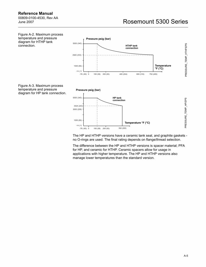
Reference Manual 00809-0100-4530, Rev AAJune 2007 Rosemount 5300 Series
Figure A-2. Maximum process temperature and pressure diagram for HTHP tank connection.
Figure A-3. Maximum process temperature and pressure diagram for HP tank connection.
The HP and HTHP versions have a ceramic tank seal, and graphite gaskets - no O-rings are used. The final rating depends on flange/thread selection.
The difference between the HP and HTHP versions is spacer material; PFA for HP, and ceramic for HTHP. Ceramic spacers allow for usage in applications with higher temperature. The HP and HTHP versions also manage lower temperatures than the standard version.
PR
ESS
UR
E_T
EMP
_HTH
P.E
PS
Temperature °F (°C)
Pressure psig (bar)
HTHP tank connection
PR
ES
SUR
E_TE
MP
_HP.
EPS
Temperature °F (°C)
Pressure psig (bar)
HP tank connection
A-5
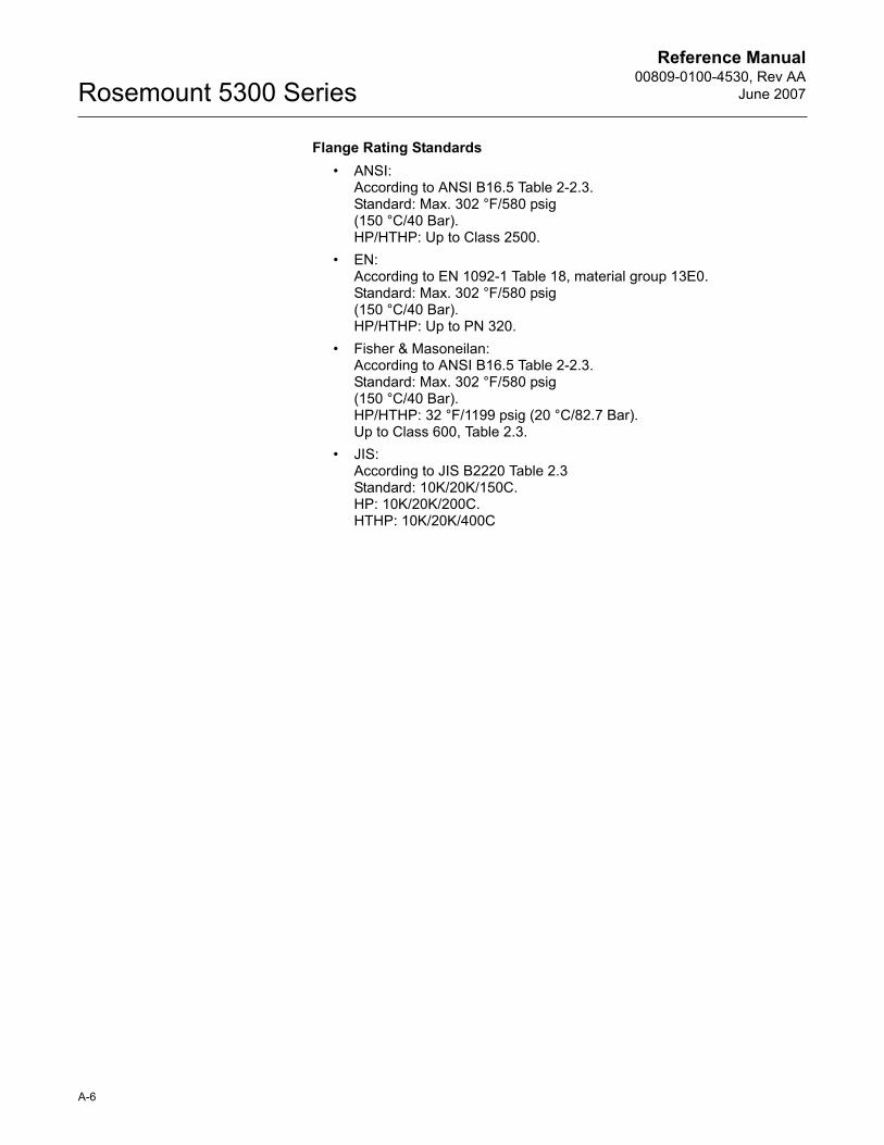
Reference Manual00809-0100-4530, Rev AA
June 2007Rosemount 5300 Series
Flange Rating Standards� ANSI:
According to ANSI B16.5 Table 2-2.3.Standard: Max. 302 °F/580 psig (150 °C/40 Bar).HP/HTHP: Up to Class 2500.
� EN:According to EN 1092-1 Table 18, material group 13E0.Standard: Max. 302 °F/580 psig (150 °C/40 Bar).HP/HTHP: Up to PN 320.
� Fisher & Masoneilan:According to ANSI B16.5 Table 2-2.3.Standard: Max. 302 °F/580 psig (150 °C/40 Bar).HP/HTHP: 32 °F/1199 psig (20 °C/82.7 Bar). Up to Class 600, Table 2.3.
� JIS:According to JIS B2220 Table 2.3Standard: 10K/20K/150C.HP: 10K/20K/200C.HTHP: 10K/20K/400C
A-6
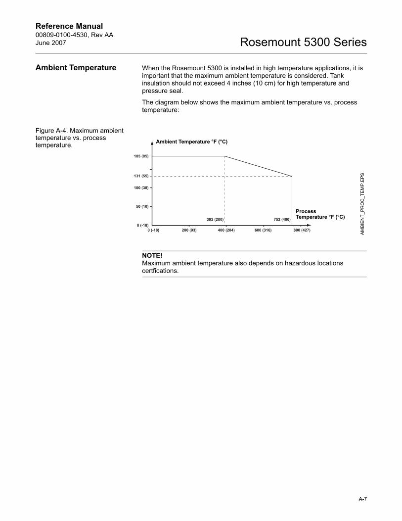
Reference Manual 00809-0100-4530, Rev AAJune 2007 Rosemount 5300 Series
Ambient Temperature When the Rosemount 5300 is installed in high temperature applications, it is important that the maximum ambient temperature is considered. Tank insulation should not exceed 4 inches (10 cm) for high temperature and pressure seal.
The diagram below shows the maximum ambient temperature vs. process temperature:
Figure A-4. Maximum ambient temperature vs. process temperature.
NOTE!Maximum ambient temperature also depends on hazardous locations certfications.
AM
BIE
NT_
PR
OC
_TE
MP
.EPS
Process Temperature °F (°C)
Ambient Temperature °F (°C)
A-7
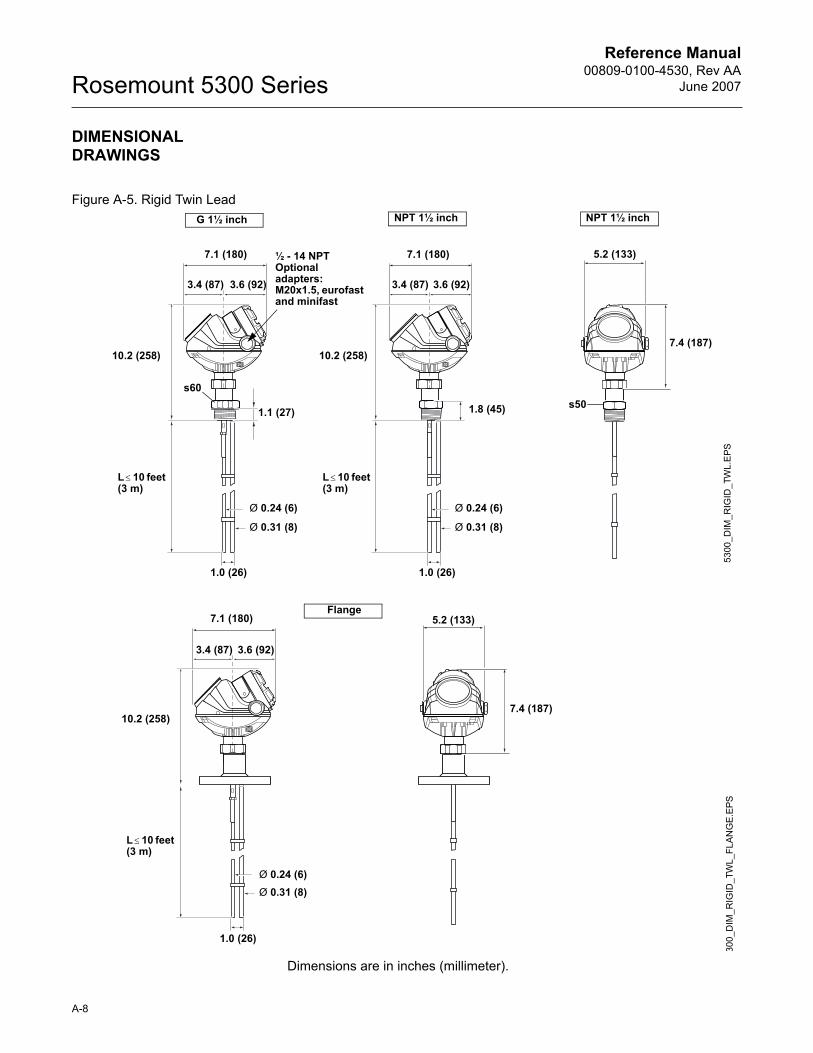
Reference Manual00809-0100-4530, Rev AA
June 2007Rosemount 5300 Series
DIMENSIONAL DRAWINGS
Figure A-5. Rigid Twin Lead
Dimensions are in inches (millimeter).
1.0 (26)
s60
5300
_DIM
_RIG
ID_T
WL.
EPS
5.2 (133)
7.4 (187)
1.8 (45)
7.1 (180)
L ≤ 10 feet (3 m)
3.4 (87)
Ø 0.24 (6)
Ø 0.31 (8)
½ - 14 NPTOptional adapters:M20x1.5, eurofast and minifast
G 1½ inch NPT 1½ inch NPT 1½ inch
s501.1 (27)
7.1 (180)
3.6 (92) 3.6 (92)3.4 (87)
10.2 (258)
1.0 (26)
Ø 0.31 (8)
Ø 0.24 (6)
L ≤ 10 feet (3 m)
10.2 (258)
300_
DIM
_RIG
ID_T
WL_
FLA
NG
E.EP
S
Ø 0.24 (6)Ø 0.31 (8)
Flange
3.4 (87) 3.6 (92)
7.1 (180) 5.2 (133)
7.4 (187)
1.0 (26)
L ≤ 10 feet (3 m)
10.2 (258)
A-8
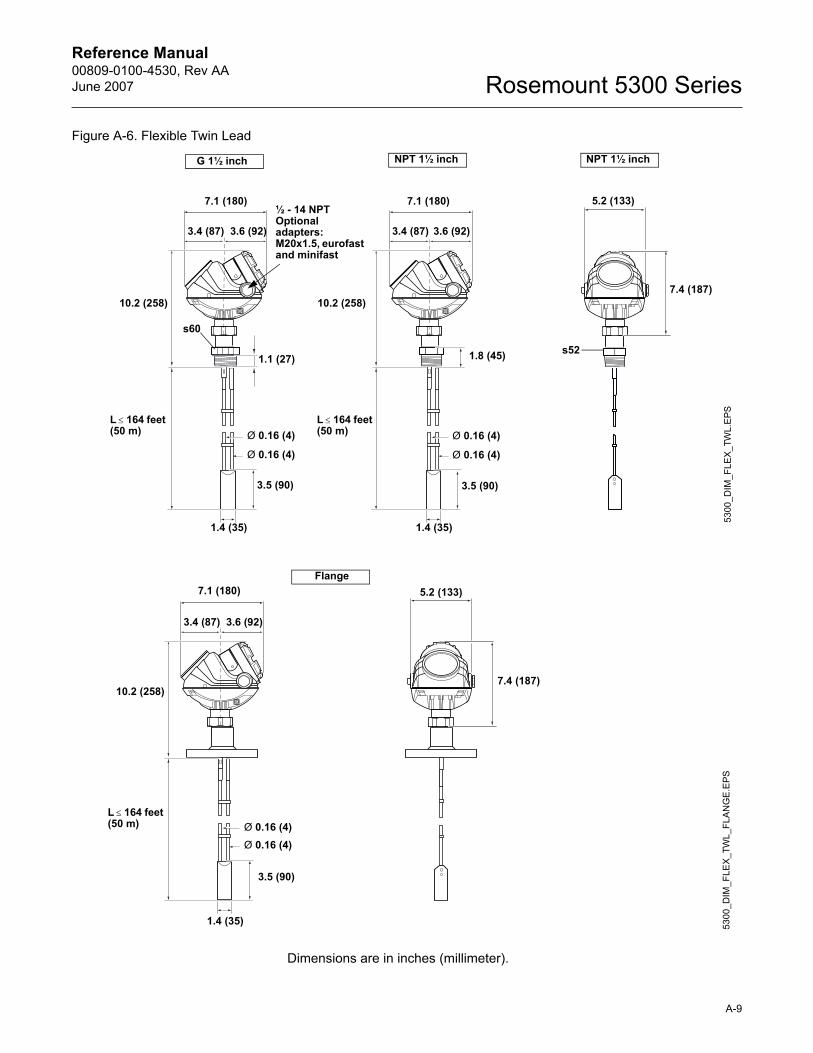
Reference Manual 00809-0100-4530, Rev AAJune 2007 Rosemount 5300 Series
Figure A-6. Flexible Twin Lead
Dimensions are in inches (millimeter).
1.4 (35)
s60
3.5 (90) 3.5 (90)
Ø 0.16 (4)
Ø 0.16 (4)
1.4 (35)
5300
_DIM
_FLE
X_TW
L.E
PS
5.2 (133)
7.4 (187)
1.8 (45)
L ≤ 164 feet (50 m)
7.1 (180)
3.4 (87)
Ø 0.16 (4)
Ø 0.16 (4)
G 1½ inch NPT 1½ inch NPT 1½ inch
s521.1 (27)
7.1 (180)
3.6 (92) 3.6 (92)3.4 (87)
L ≤ 164 feet (50 m)
10.2 (258) 10.2 (258)
½ - 14 NPTOptional adapters:M20x1.5, eurofast and minifast
5300
_DIM
_FLE
X_T
WL_
FLA
NG
E.E
PS
3.5 (90)
1.4 (35)
Ø 0.16 (4)Ø 0.16 (4)
Flange
3.4 (87) 3.6 (92)
7.1 (180) 5.2 (133)
7.4 (187)
L ≤ 164 feet (50 m)
10.2 (258)
A-9
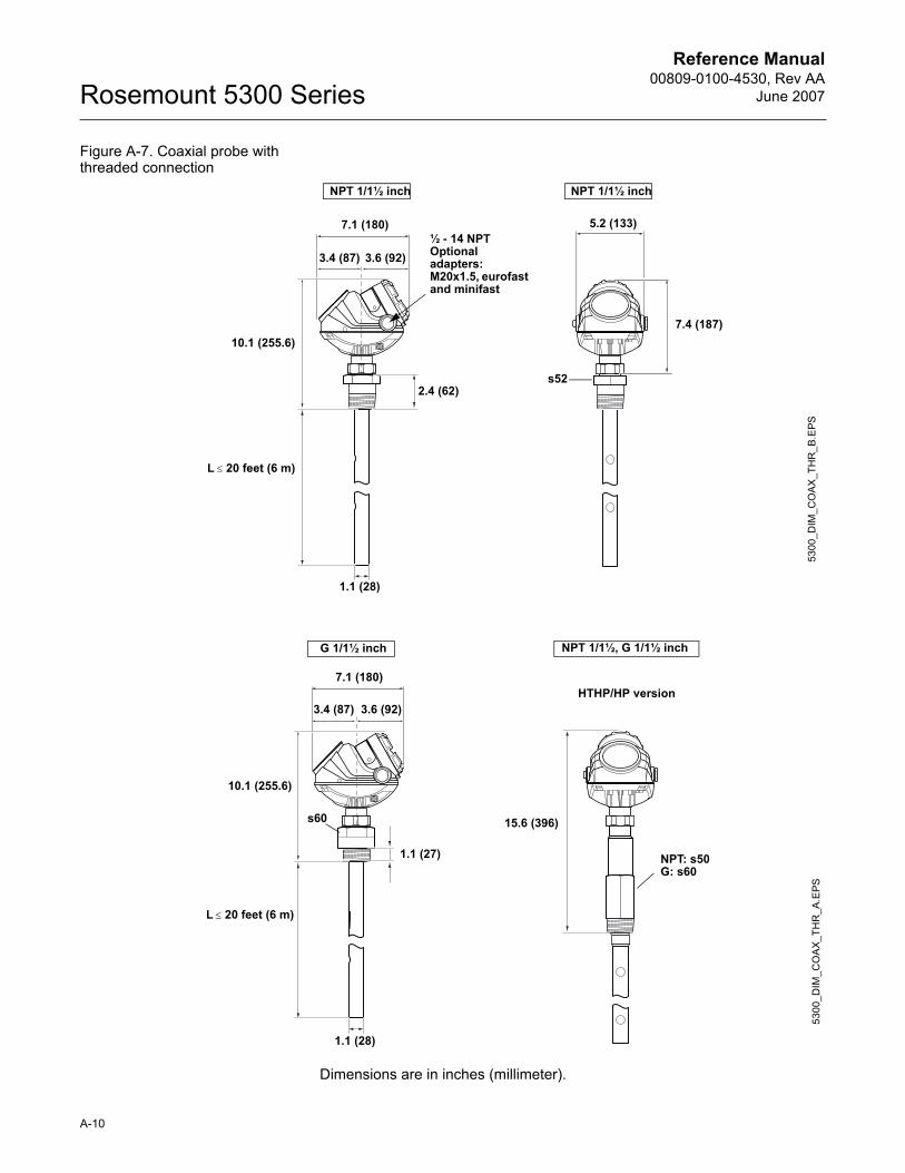
Reference Manual00809-0100-4530, Rev AA
June 2007Rosemount 5300 Series
Figure A-7. Coaxial probe with threaded connection
Dimensions are in inches (millimeter).
5300
_DIM
_CO
AX
_TH
R_B
.EPS
L ≤ 20 feet (6 m)
NPT 1/1½ inch NPT 1/1½ inch
5.2 (133)
7.4 (187)
2.4 (62)
7.1 (180)
s52
3.6 (92)3.4 (87)
1.1 (28)
10.1 (255.6)
½ - 14 NPTOptional adapters:M20x1.5, eurofast and minifast
1.1 (28)
5300
_DIM
_CO
AX_
THR
_A.E
PS
G 1/1½ inch
s60
3.4 (87)
1.1 (27)
7.1 (180)
3.6 (92)
10.1 (255.6)
NPT: s50G: s60
15.6 (396)
HTHP/HP version
L ≤ 20 feet (6 m)
NPT 1/1½, G 1/1½ inch
A-10
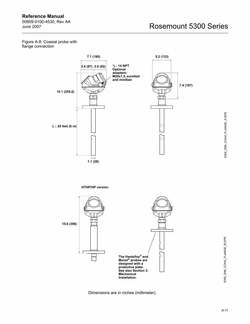
Reference Manual 00809-0100-4530, Rev AAJune 2007 Rosemount 5300 Series
Figure A-8. Coaxial probe with flange connection
Dimensions are in inches (millimeter).
5300
_DIM
_CO
AX
_FLA
NG
E_A
.EPS
L ≤ 20 feet (6 m)
10.1 (255.6)
5.2 (133)7.1 (180)
3.4 (87) 3.6 (92)
1.1 (28)
7.4 (187)
½ - 14 NPTOptional adapters:M20x1.5, eurofast and minifast
5300
_DIM
_CO
AX_
FLA
NG
E_B
.EPS
The Hastelloy® and Monel® probes are designed with a protective plate.See also Section 3: Mechanical Installation.
HTHP/HP version
15.6 (396)
A-11
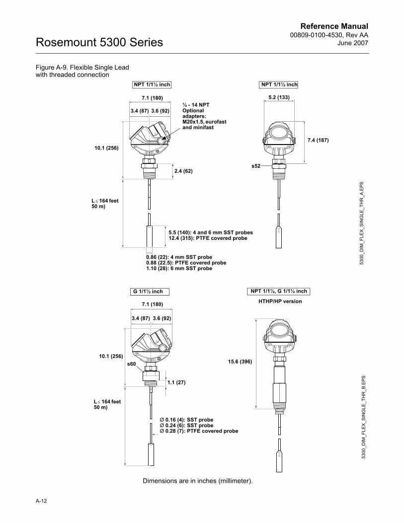
Reference Manual00809-0100-4530, Rev AA
June 2007Rosemount 5300 Series
Figure A-9. Flexible Single Lead with threaded connection
Dimensions are in inches (millimeter).
NPT 1/1½ inch
5300
_DIM
_FLE
X_S
ING
LE_T
HR
_A.E
PS
NPT 1/1½ inch
5.5 (140): 4 and 6 mm SST probes12.4 (315): PTFE covered probe
5.2 (133)
7.4 (187)
2.4 (62)
7.1 (180)
s52
3.6 (92)3.4 (87)
L ≤ 164 feet 50 m)
0.86 (22): 4 mm SST probe0.88 (22.5): PTFE covered probe1.10 (28): 6 mm SST probe
10.1 (256)
½ - 14 NPTOptional adapters:M20x1.5, eurofast and minifast
5300
_DIM
_FLE
X_S
ING
LE_T
HR
_B.E
PS
G 1/1½ inch
L ≤ 164 feet 50 m)
s60
3.4 (87)
1.1 (27)
7.1 (180)
3.6 (92)
Ø 0.16 (4): SST probeØ 0.24 (6): SST probeØ 0.28 (7): PTFE covered probe
15.6 (396)
HTHP/HP version
10.1 (256)
NPT 1/1½, G 1/1½ inch
A-12
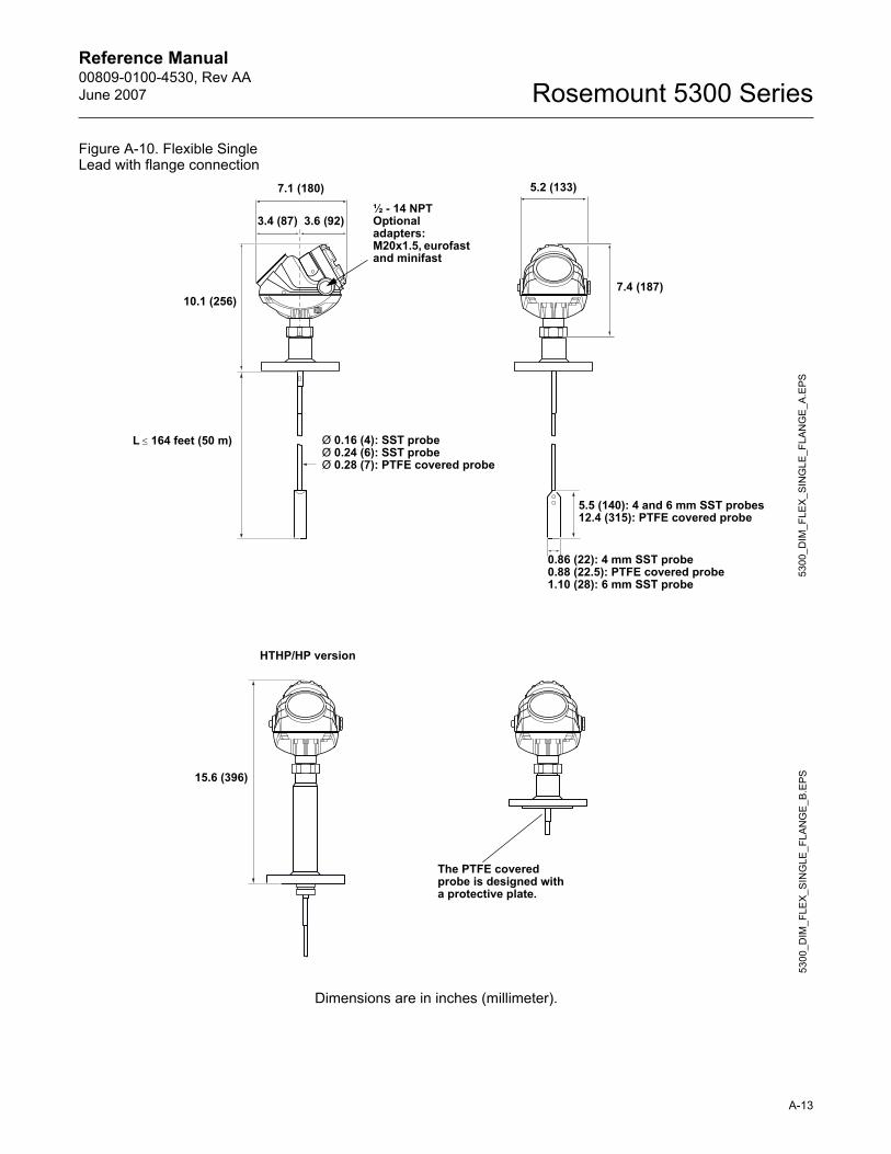
Reference Manual 00809-0100-4530, Rev AAJune 2007 Rosemount 5300 Series
Figure A-10. Flexible Single Lead with flange connection
Dimensions are in inches (millimeter).
5300
_DIM
_FLE
X_S
ING
LE_F
LAN
GE
_A.E
PS
5.2 (133)7.1 (180)
3.4 (87) 3.6 (92)
L ≤ 164 feet (50 m)
7.4 (187)10.1 (256)
Ø 0.16 (4): SST probeØ 0.24 (6): SST probeØ 0.28 (7): PTFE covered probe
5.5 (140): 4 and 6 mm SST probes12.4 (315): PTFE covered probe
0.86 (22): 4 mm SST probe0.88 (22.5): PTFE covered probe1.10 (28): 6 mm SST probe
½ - 14 NPTOptional adapters:M20x1.5, eurofast and minifast
5300
_DIM
_FLE
X_S
ING
LE_F
LAN
GE
_B.E
PS
The PTFE covered probe is designed with a protective plate.
15.6 (396)
HTHP/HP version
A-13
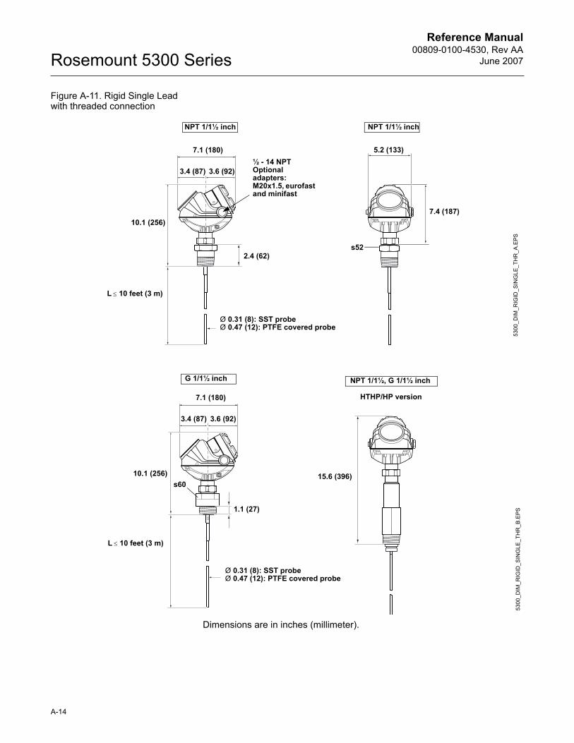
Reference Manual00809-0100-4530, Rev AA
June 2007Rosemount 5300 Series
Figure A-11. Rigid Single Lead with threaded connection
Dimensions are in inches (millimeter).
5300
_DIM
_RIG
ID_S
ING
LE_T
HR
_A.E
PS
NPT 1/1½ inch NPT 1/1½ inch
5.2 (133)
2.4 (62)
7.1 (180)
s52
3.6 (92)3.4 (87)
Ø 0.31 (8): SST probeØ 0.47 (12): PTFE covered probe
7.4 (187)10.1 (256)
½ - 14 NPTOptional adapters:M20x1.5, eurofast and minifast
L ≤ 10 feet (3 m)
5300
_DIM
_RIG
ID_S
ING
LE_T
HR
_B.E
PS
s60
3.4 (87)
1.1 (27)
7.1 (180)
3.6 (92)
L ≤ 10 feet (3 m)
HTHP/HP version
15.6 (396)10.1 (256)
Ø 0.31 (8): SST probeØ 0.47 (12): PTFE covered probe
G 1/1½ inch NPT 1/1½, G 1/1½ inch
A-14
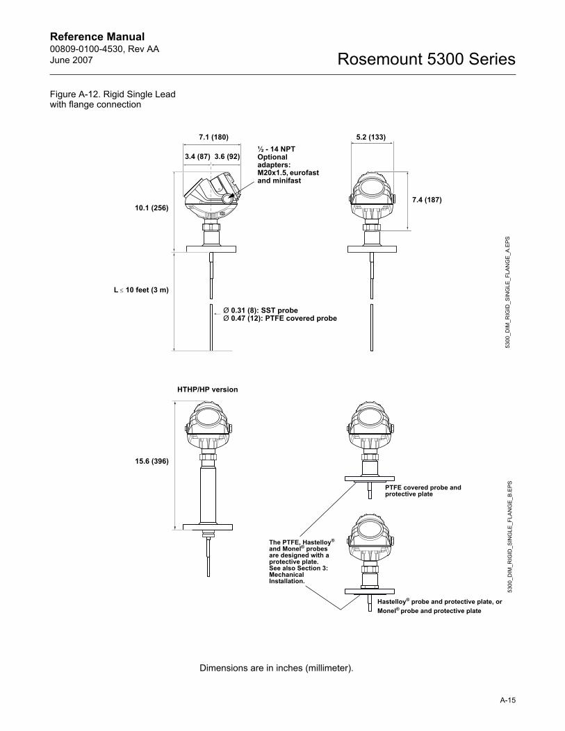
Reference Manual 00809-0100-4530, Rev AAJune 2007 Rosemount 5300 Series
Figure A-12. Rigid Single Lead with flange connection
Dimensions are in inches (millimeter).
5300
_DIM
_RIG
ID_S
ING
LE_F
LAN
GE
_A.E
PS
L ≤ 10 feet (3 m)
5.2 (133)7.1 (180)
3.4 (87) 3.6 (92)
7.4 (187)10.1 (256)
Ø 0.31 (8): SST probeØ 0.47 (12): PTFE covered probe
½ - 14 NPTOptional adapters:M20x1.5, eurofast and minifast
5300
_DIM
_RIG
ID_S
ING
LE_F
LAN
GE
_B.E
PS
The PTFE, Hastelloy® and Monel® probes are designed with a protective plate.See also Section 3: Mechanical Installation.
HTHP/HP version
15.6 (396)
PTFE covered probe and protective plate
Hastelloy® probe and protective plate, orMonel® probe and protective plate
A-15
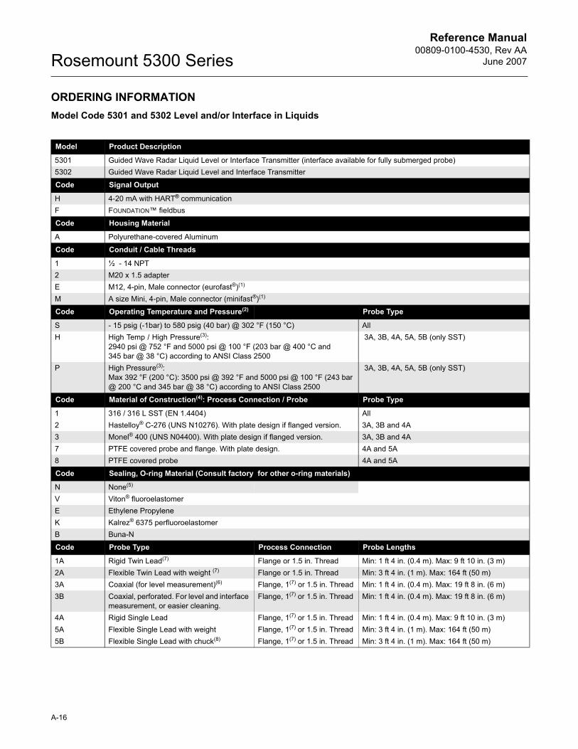
Reference Manual00809-0100-4530, Rev AA
June 2007Rosemount 5300 Series
ORDERING INFORMATIONModel Code 5301 and 5302 Level and/or Interface in Liquids
Model Product Description
5301 Guided Wave Radar Liquid Level or Interface Transmitter (interface available for fully submerged probe)5302 Guided Wave Radar Liquid Level and Interface Transmitter
Code Signal Output
H 4-20 mA with HART® communicationF FOUNDATION� fieldbus
Code Housing Material
A Polyurethane-covered Aluminum
Code Conduit / Cable Threads
1 ½ - 14 NPT2 M20 x 1.5 adapterE M12, 4-pin, Male connector (eurofast®)(1)
M A size Mini, 4-pin, Male connector (minifast®)(1)
Code Operating Temperature and Pressure(2) Probe Type
S - 15 psig (-1bar) to 580 psig (40 bar) @ 302 °F (150 °C) AllH High Temp / High Pressure(3):
2940 psi @ 752 °F and 5000 psi @ 100 °F (203 bar @ 400 °C and 345 bar @ 38 °C) according to ANSI Class 2500
3A, 3B, 4A, 5A, 5B (only SST)
P High Pressure(3):Max 392 °F (200 °C): 3500 psi @ 392 °F and 5000 psi @ 100 °F (243 bar @ 200 °C and 345 bar @ 38 °C) according to ANSI Class 2500
3A, 3B, 4A, 5A, 5B (only SST)
Code Material of Construction(4): Process Connection / Probe Probe Type
1 316 / 316 L SST (EN 1.4404) All2 Hastelloy® C-276 (UNS N10276). With plate design if flanged version. 3A, 3B and 4A3 Monel® 400 (UNS N04400). With plate design if flanged version. 3A, 3B and 4A7 PTFE covered probe and flange. With plate design. 4A and 5A8 PTFE covered probe 4A and 5A
Code Sealing, O-ring Material (Consult factory for other o-ring materials)
N None(5)
V Viton® fluoroelastomerE Ethylene PropyleneK Kalrez® 6375 perfluoroelastomerB Buna-N
Code Probe Type Process Connection Probe Lengths
1A Rigid Twin Lead(7) Flange or 1.5 in. Thread Min: 1 ft 4 in. (0.4 m). Max: 9 ft 10 in. (3 m)2A Flexible Twin Lead with weight (7) Flange or 1.5 in. Thread Min: 3 ft 4 in. (1 m). Max: 164 ft (50 m)3A Coaxial (for level measurement)(6) Flange, 1(7) or 1.5 in. Thread Min: 1 ft 4 in. (0.4 m). Max: 19 ft 8 in. (6 m)3B Coaxial, perforated. For level and interface
measurement, or easier cleaning.Flange, 1(7) or 1.5 in. Thread Min: 1 ft 4 in. (0.4 m). Max: 19 ft 8 in. (6 m)
4A Rigid Single Lead Flange, 1(7) or 1.5 in. Thread Min: 1 ft 4 in. (0.4 m). Max: 9 ft 10 in. (3 m)5A Flexible Single Lead with weight Flange, 1(7) or 1.5 in. Thread Min: 3 ft 4 in. (1 m). Max: 164 ft (50 m)5B Flexible Single Lead with chuck(8) Flange, 1(7) or 1.5 in. Thread Min: 3 ft 4 in. (1 m). Max: 164 ft (50 m)
A-16
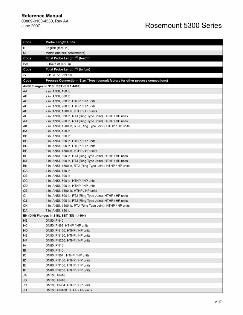
Reference Manual 00809-0100-4530, Rev AAJune 2007 Rosemount 5300 Series
Code Probe Length Units
E English (feet, in.)M Metric (meters, centimeters)
Code Total Probe Length (9) (feet/m)
xxx 0-164 ft or 0-50 m
Code Total Probe Length (9) (in./cm)
xx 0-11 in. or 0-99 cm
Code Process Connection - Size / Type (consult factory for other process connections)
ANSI Flanges in 316L SST (EN 1.4404)AA 2 in. ANSI, 150 lbAB 2 in. ANSI, 300 lbAC 2 in. ANSI, 600 lb. HTHP / HP unitsAD 2 in. ANSI, 900 lb. HTHP / HP unitsAE 2 in. ANSI, 1500 lb. HTHP / HP unitsAI 2 in. ANSI, 600 lb, RTJ (Ring Type Joint). HTHP / HP unitsAJ 2 in. ANSI, 900 lb, RTJ (Ring Type Joint). HTHP / HP unitsAK 2 in. ANSI, 1500 lb, RTJ (Ring Type Joint). HTHP / HP unitsBA 3 in. ANSI, 150 lbBB 3 in. ANSI, 300 lbBC 3 in. ANSI, 600 lb. HTHP / HP unitsBD 3 in. ANSI, 900 lb. HTHP / HP unitsBE 3 in. ANSI, 1500 lb. HTHP / HP unitsBI 3 in. ANSI, 600 lb, RTJ (Ring Type Joint). HTHP / HP unitsBJ 3 in. ANSI, 900 lb, RTJ (Ring Type Joint). HTHP / HP unitsBK 3 in. ANSI, 1500 lb, RTJ (Ring Type Joint). HTHP / HP unitsCA 4 in. ANSI, 150 lbCB 4 in. ANSI, 300 lbCC 4 in. ANSI, 600 lb. HTHP / HP unitsCD 4 in. ANSI, 900 lb. HTHP / HP unitsCE 4 in. ANSI, 1500 lb. HTHP / HP unitsCI 4 in. ANSI, 600 lb, RTJ (Ring Type Joint). HTHP / HP unitsCJ 4 in. ANSI, 900 lb, RTJ (Ring Type Joint). HTHP / HP unitsCK 4 in. ANSI, 1500 lb, RTJ (Ring Type Joint). HTHP / HP unitsDA 6 in. ANSI, 150 lbEN (DIN) Flanges in 316L SST (EN 1.4404)HB DN50, PN40HC DN50, PN63. HTHP / HP unitsHD DN50, PN100. HTHP / HP unitsHE DN50, PN160. HTHP / HP unitsHF DN50, PN250. HTHP / HP unitsIA DN80, PN16IB DN80, PN40IC DN80, PN64 . HTHP / HP unitsID DN80, PN100. HTHP / HP unitsIE DN80, PN160. HTHP / HP unitsIF DN80, PN250. HTHP / HP unitsJA DN100, PN16JB DN100, PN40JC DN100, PN64. HTHP / HP unitsJD DN100, PN100. HTHP / HP units
A-17
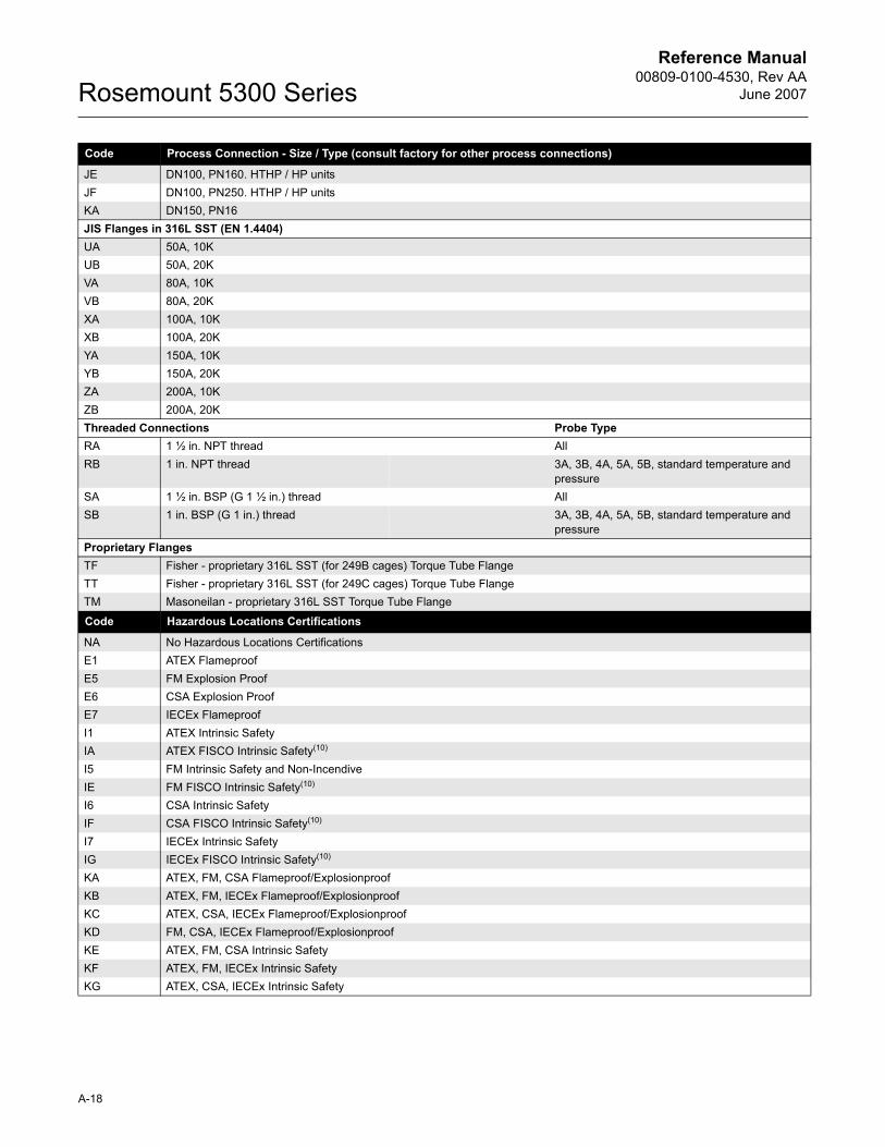
Reference Manual00809-0100-4530, Rev AA
June 2007Rosemount 5300 Series
Code Process Connection - Size / Type (consult factory for other process connections)
JE DN100, PN160. HTHP / HP unitsJF DN100, PN250. HTHP / HP unitsKA DN150, PN16JIS Flanges in 316L SST (EN 1.4404)UA 50A, 10KUB 50A, 20KVA 80A, 10KVB 80A, 20KXA 100A, 10KXB 100A, 20KYA 150A, 10KYB 150A, 20KZA 200A, 10KZB 200A, 20KThreaded Connections Probe TypeRA 1 ½ in. NPT thread AllRB 1 in. NPT thread 3A, 3B, 4A, 5A, 5B, standard temperature and
pressureSA 1 ½ in. BSP (G 1 ½ in.) thread AllSB 1 in. BSP (G 1 in.) thread 3A, 3B, 4A, 5A, 5B, standard temperature and
pressureProprietary FlangesTF Fisher - proprietary 316L SST (for 249B cages) Torque Tube FlangeTT Fisher - proprietary 316L SST (for 249C cages) Torque Tube FlangeTM Masoneilan - proprietary 316L SST Torque Tube Flange
Code Hazardous Locations Certifications
NA No Hazardous Locations CertificationsE1 ATEX FlameproofE5 FM Explosion ProofE6 CSA Explosion ProofE7 IECEx FlameproofI1 ATEX Intrinsic SafetyIA ATEX FISCO Intrinsic Safety(10) I5 FM Intrinsic Safety and Non-IncendiveIE FM FISCO Intrinsic Safety(10) I6 CSA Intrinsic SafetyIF CSA FISCO Intrinsic Safety(10)
I7 IECEx Intrinsic SafetyIG IECEx FISCO Intrinsic Safety(10)
KA ATEX, FM, CSA Flameproof/ExplosionproofKB ATEX, FM, IECEx Flameproof/ExplosionproofKC ATEX, CSA, IECEx Flameproof/ExplosionproofKD FM, CSA, IECEx Flameproof/ExplosionproofKE ATEX, FM, CSA Intrinsic Safety KF ATEX, FM, IECEx Intrinsic Safety KG ATEX, CSA, IECEx Intrinsic Safety
A-18
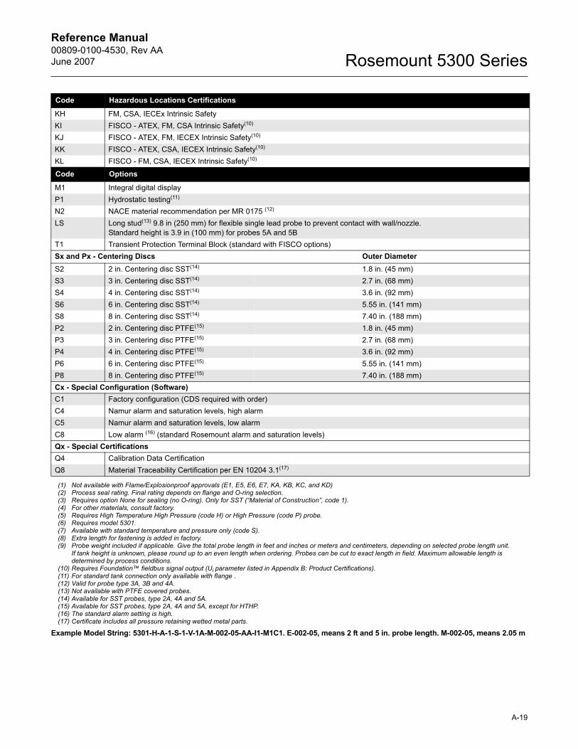
Reference Manual 00809-0100-4530, Rev AAJune 2007 Rosemount 5300 Series
Code Hazardous Locations Certifications
KH FM, CSA, IECEx Intrinsic SafetyKI FISCO - ATEX, FM, CSA Intrinsic Safety(10)
KJ FISCO - ATEX, FM, IECEX Intrinsic Safety(10) KK FISCO - ATEX, CSA, IECEX Intrinsic Safety(10) KL FISCO - FM, CSA, IECEX Intrinsic Safety(10)
Code Options
M1 Integral digital displayP1 Hydrostatic testing(11)
N2 NACE material recommendation per MR 0175 (12)
LS Long stud(13) 9.8 in (250 mm) for flexible single lead probe to prevent contact with wall/nozzle.Standard height is 3.9 in (100 mm) for probes 5A and 5B
T1 Transient Protection Terminal Block (standard with FISCO options)Sx and Px - Centering Discs Outer DiameterS2 2 in. Centering disc SST(14) 1.8 in. (45 mm)S3 3 in. Centering disc SST(14) 2.7 in. (68 mm)S4 4 in. Centering disc SST(14) 3.6 in. (92 mm)S6 6 in. Centering disc SST(14) 5.55 in. (141 mm)S8 8 in. Centering disc SST(14) 7.40 in. (188 mm)P2 2 in. Centering disc PTFE(15) 1.8 in. (45 mm)P3 3 in. Centering disc PTFE(15) 2.7 in. (68 mm)P4 4 in. Centering disc PTFE(15) 3.6 in. (92 mm)P6 6 in. Centering disc PTFE(15) 5.55 in. (141 mm)P8 8 in. Centering disc PTFE(15) 7.40 in. (188 mm)Cx - Special Configuration (Software)C1 Factory configuration (CDS required with order)C4 Namur alarm and saturation levels, high alarmC5 Namur alarm and saturation levels, low alarmC8 Low alarm (16) (standard Rosemount alarm and saturation levels)Qx - Special CertificationsQ4 Calibration Data CertificationQ8 Material Traceability Certification per EN 10204 3.1(17)
(1) Not available with Flame/Explosionproof approvals (E1, E5, E6, E7, KA, KB, KC, and KD)(2) Process seal rating. Final rating depends on flange and O-ring selection.(3) Requires option None for sealing (no O-ring). Only for SST (�Material of Construction�, code 1).(4) For other materials, consult factory.(5) Requires High Temperature High Pressure (code H) or High Pressure (code P) probe.(6) Requires model 5301.(7) Available with standard temperature and pressure only (code S).(8) Extra length for fastening is added in factory.(9) Probe weight included if applicable. Give the total probe length in feet and inches or meters and centimeters, depending on selected probe length unit.
If tank height is unknown, please round up to an even length when ordering. Probes can be cut to exact length in field. Maximum allowable length is determined by process conditions.
(10) Requires Foundation� fieldbus signal output (Ui parameter listed in Appendix B: Product Certifications).(11) For standard tank connection only available with flange .(12) Valid for probe type 3A, 3B and 4A.(13) Not available with PTFE covered probes.(14) Available for SST probes, type 2A, 4A and 5A.(15) Available for SST probes, type 2A, 4A and 5A, except for HTHP.(16) The standard alarm setting is high.(17) Certificate includes all pressure retaining wetted metal parts.
Example Model String: 5301-H-A-1-S-1-V-1A-M-002-05-AA-I1-M1C1. E-002-05, means 2 ft and 5 in. probe length. M-002-05, means 2.05 m
A-19
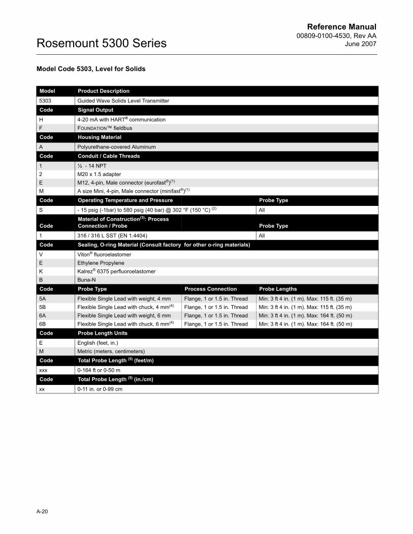
Reference Manual00809-0100-4530, Rev AA
June 2007Rosemount 5300 Series
Model Code 5303, Level for Solids
Model Product Description
5303 Guided Wave Solids Level Transmitter
Code Signal Output
H 4-20 mA with HART® communicationF FOUNDATION� fieldbus
Code Housing Material
A Polyurethane-covered Aluminum
Code Conduit / Cable Threads
1 ½ - 14 NPT2 M20 x 1.5 adapterE M12, 4-pin, Male connector (eurofast®)(1)
M A size Mini, 4-pin, Male connector (minifast®)(1)
Code Operating Temperature and Pressure Probe Type
S - 15 psig (-1bar) to 580 psig (40 bar) @ 302 °F (150 °C) (2) All
CodeMaterial of Construction(3): Process Connection / Probe Probe Type
1 316 / 316 L SST (EN 1.4404) All
Code Sealing, O-ring Material (Consult factory for other o-ring materials)
V Viton® fluoroelastomerE Ethylene PropyleneK Kalrez® 6375 perfluoroelastomerB Buna-N
Code Probe Type Process Connection Probe Lengths
5A Flexible Single Lead with weight, 4 mm Flange, 1 or 1.5 in. Thread Min: 3 ft 4 in. (1 m). Max: 115 ft. (35 m)5B Flexible Single Lead with chuck, 4 mm(4) Flange, 1 or 1.5 in. Thread Min: 3 ft 4 in. (1 m). Max: 115 ft. (35 m)6A Flexible Single Lead with weight, 6 mm Flange, 1 or 1.5 in. Thread Min: 3 ft 4 in. (1 m). Max: 164 ft. (50 m)6B Flexible Single Lead with chuck, 6 mm(4) Flange, 1 or 1.5 in. Thread Min: 3 ft 4 in. (1 m). Max: 164 ft. (50 m)
Code Probe Length Units
E English (feet, in.)M Metric (meters, centimeters)
Code Total Probe Length (5) (feet/m)
xxx 0-164 ft or 0-50 m
Code Total Probe Length (5) (in./cm)
xx 0-11 in. or 0-99 cm
A-20
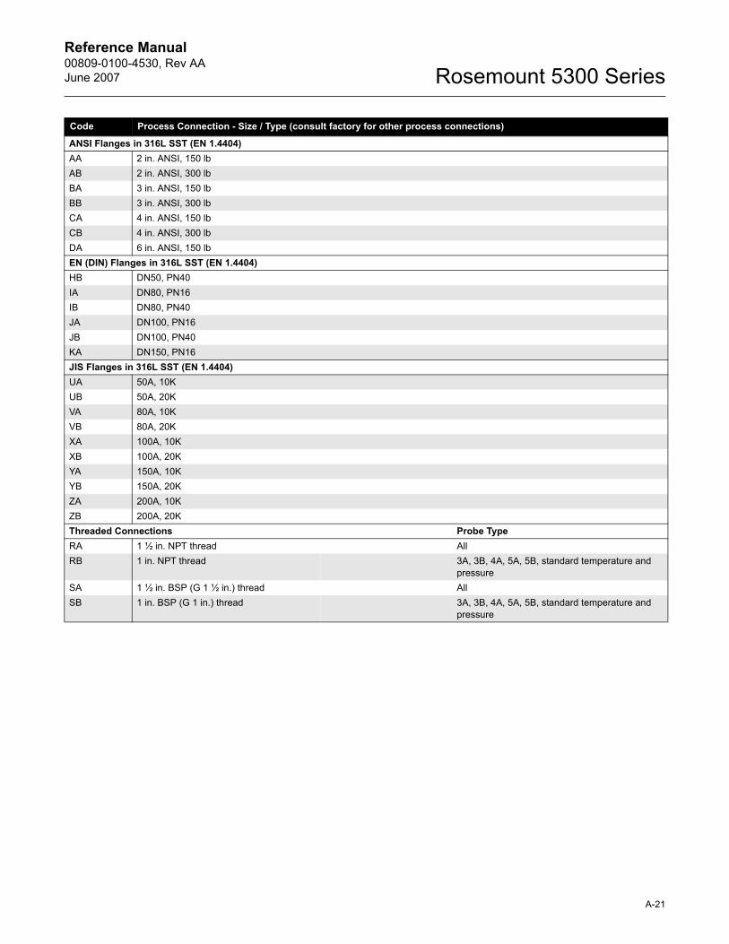
Reference Manual 00809-0100-4530, Rev AAJune 2007 Rosemount 5300 Series
Code Process Connection - Size / Type (consult factory for other process connections)
ANSI Flanges in 316L SST (EN 1.4404)AA 2 in. ANSI, 150 lbAB 2 in. ANSI, 300 lbBA 3 in. ANSI, 150 lbBB 3 in. ANSI, 300 lbCA 4 in. ANSI, 150 lbCB 4 in. ANSI, 300 lbDA 6 in. ANSI, 150 lbEN (DIN) Flanges in 316L SST (EN 1.4404)HB DN50, PN40IA DN80, PN16IB DN80, PN40JA DN100, PN16JB DN100, PN40KA DN150, PN16JIS Flanges in 316L SST (EN 1.4404)UA 50A, 10KUB 50A, 20KVA 80A, 10KVB 80A, 20KXA 100A, 10KXB 100A, 20KYA 150A, 10KYB 150A, 20KZA 200A, 10KZB 200A, 20KThreaded Connections Probe TypeRA 1 ½ in. NPT thread AllRB 1 in. NPT thread 3A, 3B, 4A, 5A, 5B, standard temperature and
pressureSA 1 ½ in. BSP (G 1 ½ in.) thread AllSB 1 in. BSP (G 1 in.) thread 3A, 3B, 4A, 5A, 5B, standard temperature and
pressure
A-21
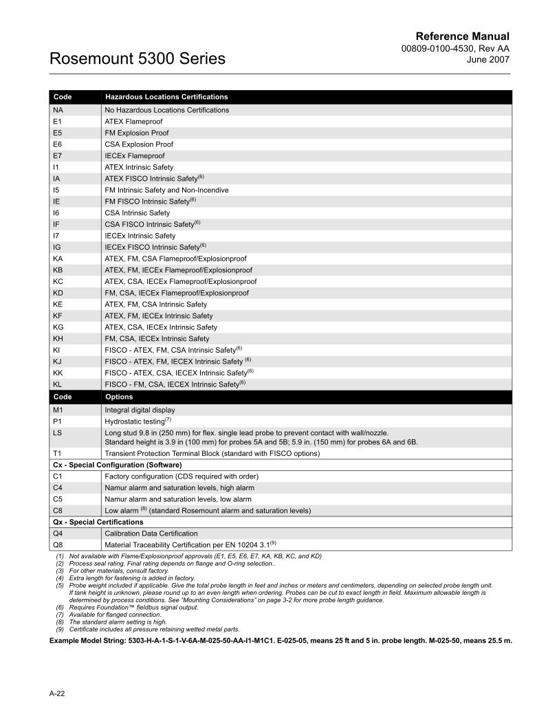
Reference Manual00809-0100-4530, Rev AA
June 2007Rosemount 5300 Series
Code Hazardous Locations Certifications
NA No Hazardous Locations CertificationsE1 ATEX FlameproofE5 FM Explosion ProofE6 CSA Explosion ProofE7 IECEx FlameproofI1 ATEX Intrinsic SafetyIA ATEX FISCO Intrinsic Safety(6) I5 FM Intrinsic Safety and Non-IncendiveIE FM FISCO Intrinsic Safety(6) I6 CSA Intrinsic SafetyIF CSA FISCO Intrinsic Safety(6)
I7 IECEx Intrinsic SafetyIG IECEx FISCO Intrinsic Safety(6)
KA ATEX, FM, CSA Flameproof/ExplosionproofKB ATEX, FM, IECEx Flameproof/ExplosionproofKC ATEX, CSA, IECEx Flameproof/ExplosionproofKD FM, CSA, IECEx Flameproof/ExplosionproofKE ATEX, FM, CSA Intrinsic Safety KF ATEX, FM, IECEx Intrinsic Safety KG ATEX, CSA, IECEx Intrinsic SafetyKH FM, CSA, IECEx Intrinsic SafetyKI FISCO - ATEX, FM, CSA Intrinsic Safety(6) KJ FISCO - ATEX, FM, IECEX Intrinsic Safety (6)
KK FISCO - ATEX, CSA, IECEX Intrinsic Safety(6) KL FISCO - FM, CSA, IECEX Intrinsic Safety(6)
Code Options
M1 Integral digital displayP1 Hydrostatic testing(7)
LS Long stud 9.8 in (250 mm) for flex. single lead probe to prevent contact with wall/nozzle.Standard height is 3.9 in (100 mm) for probes 5A and 5B; 5.9 in. (150 mm) for probes 6A and 6B.
T1 Transient Protection Terminal Block (standard with FISCO options)Cx - Special Configuration (Software)C1 Factory configuration (CDS required with order)C4 Namur alarm and saturation levels, high alarmC5 Namur alarm and saturation levels, low alarmC8 Low alarm (8) (standard Rosemount alarm and saturation levels)Qx - Special CertificationsQ4 Calibration Data CertificationQ8 Material Traceability Certification per EN 10204 3.1(9)
(1) Not available with Flame/Explosionproof approvals (E1, E5, E6, E7, KA, KB, KC, and KD)(2) Process seal rating. Final rating depends on flange and O-ring selection..(3) For other materials, consult factory.(4) Extra length for fastening is added in factory.(5) Probe weight included if applicable. Give the total probe length in feet and inches or meters and centimeters, depending on selected probe length unit.
If tank height is unknown, please round up to an even length when ordering. Probes can be cut to exact length in field. Maximum allowable length is determined by process conditions. See �Mounting Considerations� on page 3-2 for more probe length guidance.
(6) Requires Foundation� fieldbus signal output.(7) Available for flanged connection.(8) The standard alarm setting is high.(9) Certificate includes all pressure retaining wetted metal parts.
Example Model String: 5303-H-A-1-S-1-V-6A-M-025-50-AA-I1-M1C1. E-025-05, means 25 ft and 5 in. probe length. M-025-50, means 25.5 m.
A-22
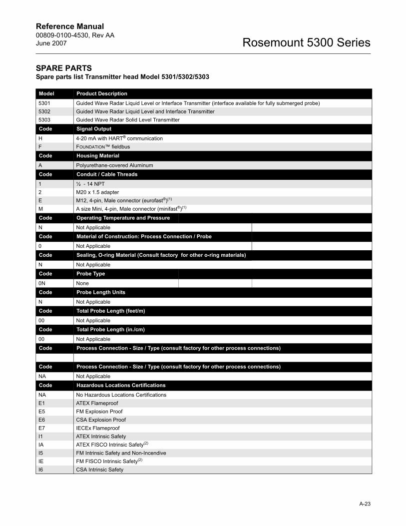
Reference Manual 00809-0100-4530, Rev AAJune 2007 Rosemount 5300 Series
SPARE PARTSSpare parts list Transmitter head Model 5301/5302/5303
Model Product Description
5301 Guided Wave Radar Liquid Level or Interface Transmitter (interface available for fully submerged probe)5302 Guided Wave Radar Liquid Level and Interface Transmitter5303 Guided Wave Radar Solid Level Transmitter
Code Signal Output
H 4-20 mA with HART® communicationF FOUNDATION� fieldbus
Code Housing Material
A Polyurethane-covered Aluminum
Code Conduit / Cable Threads
1 ½ - 14 NPT2 M20 x 1.5 adapterE M12, 4-pin, Male connector (eurofast®)(1)
M A size Mini, 4-pin, Male connector (minifast®)(1)
Code Operating Temperature and Pressure
N Not Applicable
Code Material of Construction: Process Connection / Probe
0 Not Applicable
Code Sealing, O-ring Material (Consult factory for other o-ring materials)
N Not Applicable
Code Probe Type
0N None
Code Probe Length Units
N Not Applicable
Code Total Probe Length (feet/m)
00 Not Applicable
Code Total Probe Length (in./cm)
00 Not Applicable
Code Process Connection - Size / Type (consult factory for other process connections)
Code Process Connection - Size / Type (consult factory for other process connections)
NA Not Applicable
Code Hazardous Locations Certifications
NA No Hazardous Locations CertificationsE1 ATEX FlameproofE5 FM Explosion ProofE6 CSA Explosion ProofE7 IECEx FlameproofI1 ATEX Intrinsic SafetyIA ATEX FISCO Intrinsic Safety(2) I5 FM Intrinsic Safety and Non-IncendiveIE FM FISCO Intrinsic Safety(2) I6 CSA Intrinsic Safety
A-23
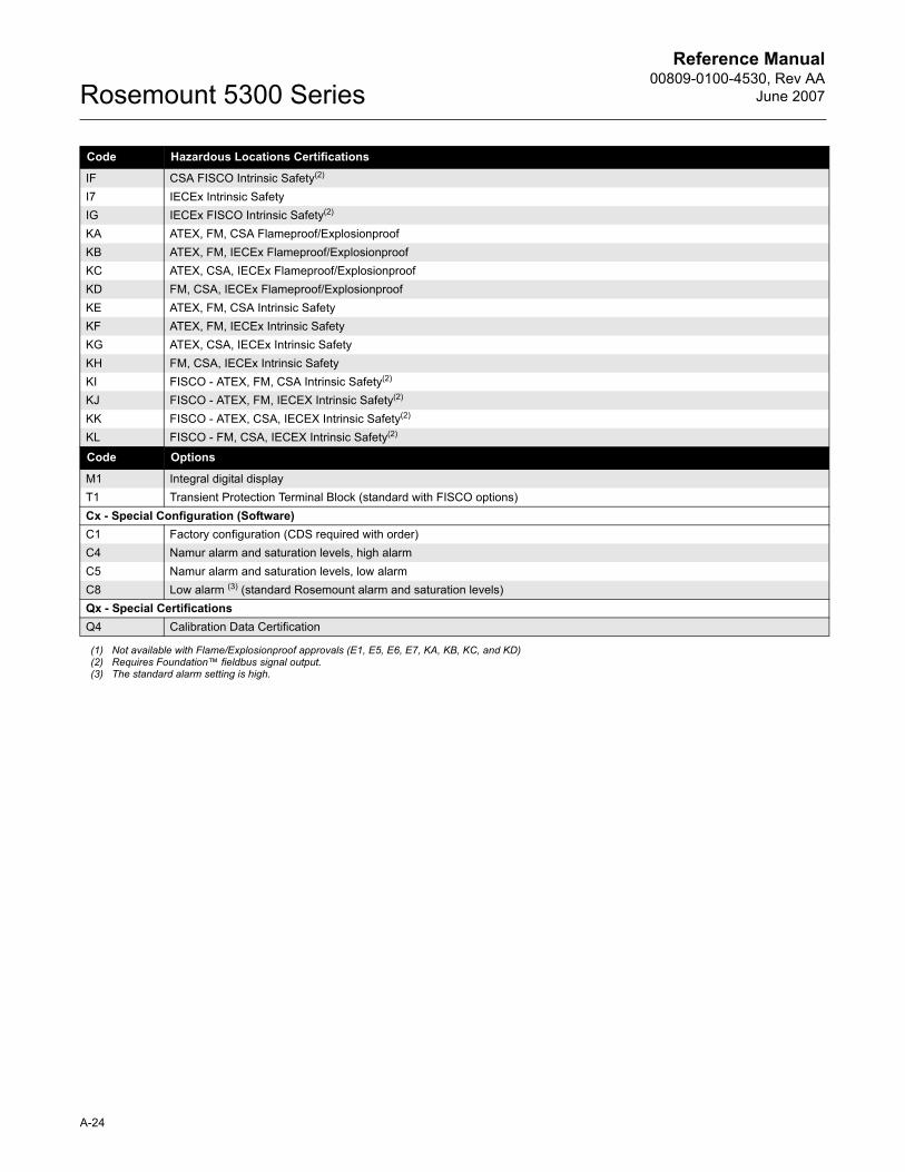
Reference Manual00809-0100-4530, Rev AA
June 2007Rosemount 5300 Series
Code Hazardous Locations Certifications
IF CSA FISCO Intrinsic Safety(2)
I7 IECEx Intrinsic SafetyIG IECEx FISCO Intrinsic Safety(2)
KA ATEX, FM, CSA Flameproof/ExplosionproofKB ATEX, FM, IECEx Flameproof/ExplosionproofKC ATEX, CSA, IECEx Flameproof/ExplosionproofKD FM, CSA, IECEx Flameproof/ExplosionproofKE ATEX, FM, CSA Intrinsic Safety KF ATEX, FM, IECEx Intrinsic Safety KG ATEX, CSA, IECEx Intrinsic SafetyKH FM, CSA, IECEx Intrinsic SafetyKI FISCO - ATEX, FM, CSA Intrinsic Safety(2)
KJ FISCO - ATEX, FM, IECEX Intrinsic Safety(2) KK FISCO - ATEX, CSA, IECEX Intrinsic Safety(2) KL FISCO - FM, CSA, IECEX Intrinsic Safety(2)
Code Options
M1 Integral digital displayT1 Transient Protection Terminal Block (standard with FISCO options)Cx - Special Configuration (Software)C1 Factory configuration (CDS required with order)C4 Namur alarm and saturation levels, high alarmC5 Namur alarm and saturation levels, low alarmC8 Low alarm (3) (standard Rosemount alarm and saturation levels)Qx - Special CertificationsQ4 Calibration Data Certification
(1) Not available with Flame/Explosionproof approvals (E1, E5, E6, E7, KA, KB, KC, and KD)(2) Requires Foundation� fieldbus signal output.(3) The standard alarm setting is high.
A-24
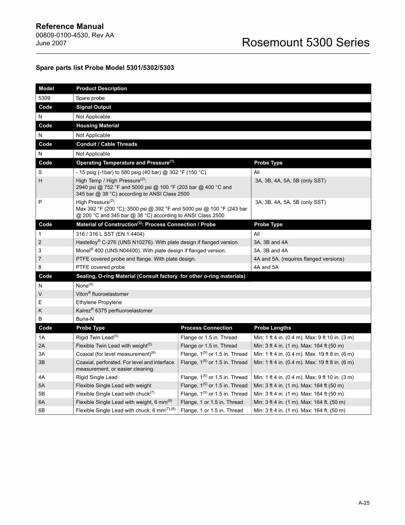
Reference Manual 00809-0100-4530, Rev AAJune 2007 Rosemount 5300 Series
Spare parts list Probe Model 5301/5302/5303
Model Product Description
5309 Spare probe
Code Signal Output
N Not Applicable
Code Housing Material
N Not Applicable
Code Conduit / Cable Threads
N Not Applicable
Code Operating Temperature and Pressure(1) Probe Type
S - 15 psig (-1bar) to 580 psig (40 bar) @ 302 °F (150 °C) AllH High Temp / High Pressure(2):
2940 psi @ 752 °F and 5000 psi @ 100 °F (203 bar @ 400 °C and 345 bar @ 38 °C) according to ANSI Class 2500
3A, 3B, 4A, 5A, 5B (only SST)
P High Pressure(2):Max 392 °F (200 °C): 3500 psi @ 392 °F and 5000 psi @ 100 °F (243 bar @ 200 °C and 345 bar @ 38 °C) according to ANSI Class 2500
3A, 3B, 4A, 5A, 5B (only SST)
Code Material of Construction(3): Process Connection / Probe Probe Type
1 316 / 316 L SST (EN 1.4404) All2 Hastelloy® C-276 (UNS N10276). With plate design if flanged version. 3A, 3B and 4A3 Monel® 400 (UNS N04400). With plate design if flanged version. 3A, 3B and 4A7 PTFE covered probe and flange. With plate design. 4A and 5A, (requires flanged versions)8 PTFE covered probe 4A and 5A
Code Sealing, O-ring Material (Consult factory for other o-ring materials)
N None(4)
V Viton® fluoroelastomerE Ethylene PropyleneK Kalrez® 6375 perfluoroelastomerB Buna-N
Code Probe Type Process Connection Probe Lengths
1A Rigid Twin Lead(5) Flange or 1.5 in. Thread Min: 1 ft 4 in. (0.4 m). Max: 9 ft 10 in. (3 m)2A Flexible Twin Lead with weight(5) Flange or 1.5 in. Thread Min: 3 ft 4 in. (1 m). Max: 164 ft (50 m)3A Coaxial (for level measurement)(6) Flange, 1(5) or 1.5 in. Thread Min: 1 ft 4 in. (0.4 m). Max: 19 ft 8 in. (6 m)3B Coaxial, perforated. For level and interface
measurement, or easier cleaning.Flange, 1(5) or 1.5 in. Thread Min: 1 ft 4 in. (0.4 m). Max: 19 ft 8 in. (6 m)
4A Rigid Single Lead Flange, 1(5) or 1.5 in. Thread Min: 1 ft 4 in. (0.4 m). Max: 9 ft 10 in. (3 m)5A Flexible Single Lead with weight Flange, 1(5) or 1.5 in. Thread Min: 3 ft 4 in. (1 m). Max: 164 ft (50 m)5B Flexible Single Lead with chuck(7) Flange, 1(5) or 1.5 in. Thread Min: 3 ft 4 in. (1 m). Max: 164 ft (50 m)6A Flexible Single Lead with weight, 6 mm(8) Flange, 1 or 1.5 in. Thread Min: 3 ft 4 in. (1 m). Max: 164 ft. (50 m)6B Flexible Single Lead with chuck, 6 mm(7),(8) Flange, 1 or 1.5 in. Thread Min: 3 ft 4 in. (1 m). Max: 164 ft. (50 m)
A-25
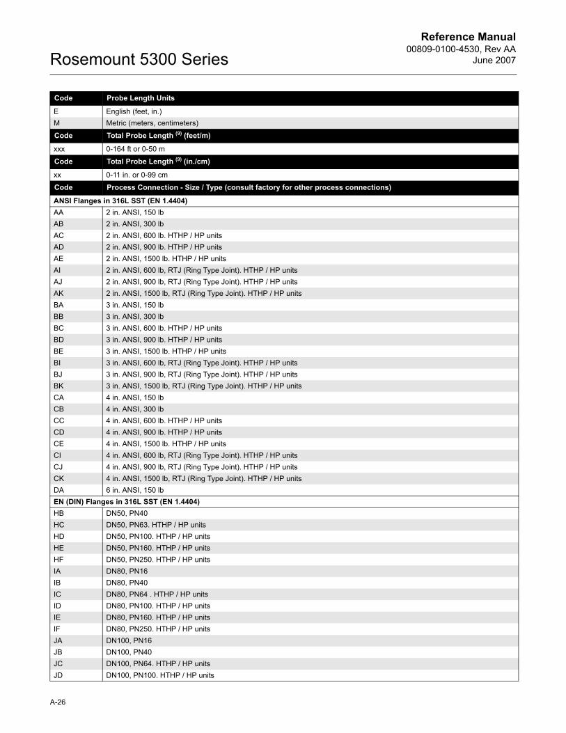
Reference Manual00809-0100-4530, Rev AA
June 2007Rosemount 5300 Series
Code Probe Length Units
E English (feet, in.)M Metric (meters, centimeters)
Code Total Probe Length (9) (feet/m)
xxx 0-164 ft or 0-50 m
Code Total Probe Length (9) (in./cm)
xx 0-11 in. or 0-99 cm
Code Process Connection - Size / Type (consult factory for other process connections)
ANSI Flanges in 316L SST (EN 1.4404)AA 2 in. ANSI, 150 lbAB 2 in. ANSI, 300 lbAC 2 in. ANSI, 600 lb. HTHP / HP unitsAD 2 in. ANSI, 900 lb. HTHP / HP unitsAE 2 in. ANSI, 1500 lb. HTHP / HP unitsAI 2 in. ANSI, 600 lb, RTJ (Ring Type Joint). HTHP / HP unitsAJ 2 in. ANSI, 900 lb, RTJ (Ring Type Joint). HTHP / HP unitsAK 2 in. ANSI, 1500 lb, RTJ (Ring Type Joint). HTHP / HP unitsBA 3 in. ANSI, 150 lbBB 3 in. ANSI, 300 lbBC 3 in. ANSI, 600 lb. HTHP / HP unitsBD 3 in. ANSI, 900 lb. HTHP / HP unitsBE 3 in. ANSI, 1500 lb. HTHP / HP unitsBI 3 in. ANSI, 600 lb, RTJ (Ring Type Joint). HTHP / HP unitsBJ 3 in. ANSI, 900 lb, RTJ (Ring Type Joint). HTHP / HP unitsBK 3 in. ANSI, 1500 lb, RTJ (Ring Type Joint). HTHP / HP unitsCA 4 in. ANSI, 150 lbCB 4 in. ANSI, 300 lbCC 4 in. ANSI, 600 lb. HTHP / HP unitsCD 4 in. ANSI, 900 lb. HTHP / HP unitsCE 4 in. ANSI, 1500 lb. HTHP / HP unitsCI 4 in. ANSI, 600 lb, RTJ (Ring Type Joint). HTHP / HP unitsCJ 4 in. ANSI, 900 lb, RTJ (Ring Type Joint). HTHP / HP unitsCK 4 in. ANSI, 1500 lb, RTJ (Ring Type Joint). HTHP / HP unitsDA 6 in. ANSI, 150 lbEN (DIN) Flanges in 316L SST (EN 1.4404)HB DN50, PN40HC DN50, PN63. HTHP / HP unitsHD DN50, PN100. HTHP / HP unitsHE DN50, PN160. HTHP / HP unitsHF DN50, PN250. HTHP / HP unitsIA DN80, PN16IB DN80, PN40IC DN80, PN64 . HTHP / HP unitsID DN80, PN100. HTHP / HP unitsIE DN80, PN160. HTHP / HP unitsIF DN80, PN250. HTHP / HP unitsJA DN100, PN16JB DN100, PN40JC DN100, PN64. HTHP / HP unitsJD DN100, PN100. HTHP / HP units
A-26
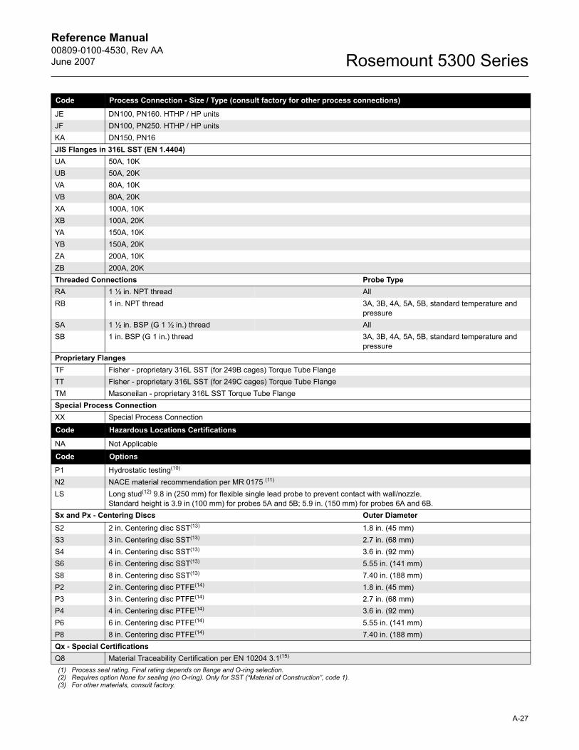
Reference Manual 00809-0100-4530, Rev AAJune 2007 Rosemount 5300 Series
Code Process Connection - Size / Type (consult factory for other process connections)
JE DN100, PN160. HTHP / HP unitsJF DN100, PN250. HTHP / HP unitsKA DN150, PN16JIS Flanges in 316L SST (EN 1.4404)UA 50A, 10KUB 50A, 20KVA 80A, 10KVB 80A, 20KXA 100A, 10KXB 100A, 20KYA 150A, 10KYB 150A, 20KZA 200A, 10KZB 200A, 20KThreaded Connections Probe TypeRA 1 ½ in. NPT thread AllRB 1 in. NPT thread 3A, 3B, 4A, 5A, 5B, standard temperature and
pressureSA 1 ½ in. BSP (G 1 ½ in.) thread AllSB 1 in. BSP (G 1 in.) thread 3A, 3B, 4A, 5A, 5B, standard temperature and
pressureProprietary FlangesTF Fisher - proprietary 316L SST (for 249B cages) Torque Tube FlangeTT Fisher - proprietary 316L SST (for 249C cages) Torque Tube FlangeTM Masoneilan - proprietary 316L SST Torque Tube FlangeSpecial Process ConnectionXX Special Process Connection
Code Hazardous Locations Certifications
NA Not Applicable
Code Options
P1 Hydrostatic testing(10)
N2 NACE material recommendation per MR 0175 (11)
LS Long stud(12) 9.8 in (250 mm) for flexible single lead probe to prevent contact with wall/nozzle.Standard height is 3.9 in (100 mm) for probes 5A and 5B; 5.9 in. (150 mm) for probes 6A and 6B.
Sx and Px - Centering Discs Outer DiameterS2 2 in. Centering disc SST(13) 1.8 in. (45 mm)S3 3 in. Centering disc SST(13) 2.7 in. (68 mm)S4 4 in. Centering disc SST(13) 3.6 in. (92 mm)S6 6 in. Centering disc SST(13) 5.55 in. (141 mm)S8 8 in. Centering disc SST(13) 7.40 in. (188 mm)P2 2 in. Centering disc PTFE(14) 1.8 in. (45 mm)P3 3 in. Centering disc PTFE(14) 2.7 in. (68 mm)P4 4 in. Centering disc PTFE(14) 3.6 in. (92 mm)P6 6 in. Centering disc PTFE(14) 5.55 in. (141 mm)P8 8 in. Centering disc PTFE(14) 7.40 in. (188 mm)Qx - Special CertificationsQ8 Material Traceability Certification per EN 10204 3.1(15)
(1) Process seal rating. Final rating depends on flange and O-ring selection.(2) Requires option None for sealing (no O-ring). Only for SST (�Material of Construction�, code 1).(3) For other materials, consult factory.
A-27
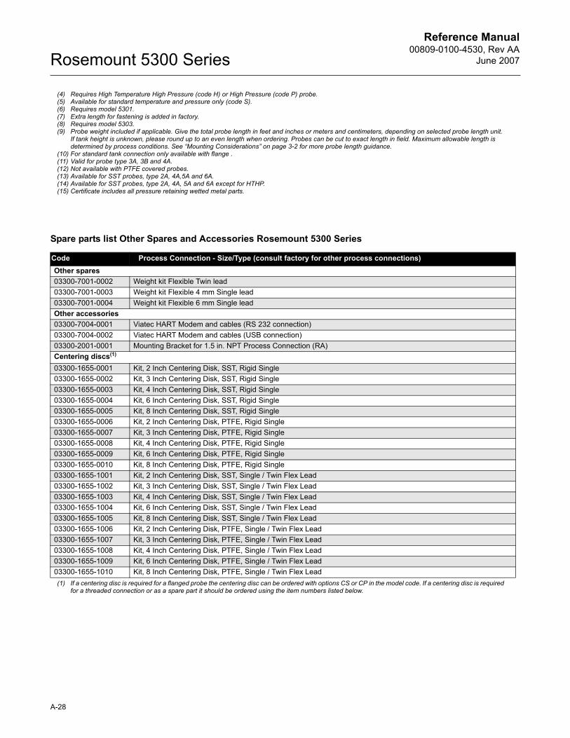
Reference Manual00809-0100-4530, Rev AA
June 2007Rosemount 5300 Series
Spare parts list Other Spares and Accessories Rosemount 5300 Series
(4) Requires High Temperature High Pressure (code H) or High Pressure (code P) probe.(5) Available for standard temperature and pressure only (code S).(6) Requires model 5301.(7) Extra length for fastening is added in factory.(8) Requires model 5303.(9) Probe weight included if applicable. Give the total probe length in feet and inches or meters and centimeters, depending on selected probe length unit.
If tank height is unknown, please round up to an even length when ordering. Probes can be cut to exact length in field. Maximum allowable length is determined by process conditions. See �Mounting Considerations� on page 3-2 for more probe length guidance.
(10) For standard tank connection only available with flange .(11) Valid for probe type 3A, 3B and 4A.(12) Not available with PTFE covered probes.(13) Available for SST probes, type 2A, 4A,5A and 6A.(14) Available for SST probes, type 2A, 4A, 5A and 6A except for HTHP.(15) Certificate includes all pressure retaining wetted metal parts.
Code Process Connection - Size/Type (consult factory for other process connections)Other spares03300-7001-0002 Weight kit Flexible Twin lead03300-7001-0003 Weight kit Flexible 4 mm Single lead03300-7001-0004 Weight kit Flexible 6 mm Single leadOther accessories03300-7004-0001 Viatec HART Modem and cables (RS 232 connection)03300-7004-0002 Viatec HART Modem and cables (USB connection)03300-2001-0001 Mounting Bracket for 1.5 in. NPT Process Connection (RA)Centering discs(1)
(1) If a centering disc is required for a flanged probe the centering disc can be ordered with options CS or CP in the model code. If a centering disc is required for a threaded connection or as a spare part it should be ordered using the item numbers listed below.
03300-1655-0001 Kit, 2 Inch Centering Disk, SST, Rigid Single 03300-1655-0002 Kit, 3 Inch Centering Disk, SST, Rigid Single 03300-1655-0003 Kit, 4 Inch Centering Disk, SST, Rigid Single 03300-1655-0004 Kit, 6 Inch Centering Disk, SST, Rigid Single 03300-1655-0005 Kit, 8 Inch Centering Disk, SST, Rigid Single 03300-1655-0006 Kit, 2 Inch Centering Disk, PTFE, Rigid Single 03300-1655-0007 Kit, 3 Inch Centering Disk, PTFE, Rigid Single 03300-1655-0008 Kit, 4 Inch Centering Disk, PTFE, Rigid Single 03300-1655-0009 Kit, 6 Inch Centering Disk, PTFE, Rigid Single 03300-1655-0010 Kit, 8 Inch Centering Disk, PTFE, Rigid Single 03300-1655-1001 Kit, 2 Inch Centering Disk, SST, Single / Twin Flex Lead03300-1655-1002 Kit, 3 Inch Centering Disk, SST, Single / Twin Flex Lead 03300-1655-1003 Kit, 4 Inch Centering Disk, SST, Single / Twin Flex Lead 03300-1655-1004 Kit, 6 Inch Centering Disk, SST, Single / Twin Flex Lead 03300-1655-1005 Kit, 8 Inch Centering Disk, SST, Single / Twin Flex Lead 03300-1655-1006 Kit, 2 Inch Centering Disk, PTFE, Single / Twin Flex Lead03300-1655-1007 Kit, 3 Inch Centering Disk, PTFE, Single / Twin Flex Lead 03300-1655-1008 Kit, 4 Inch Centering Disk, PTFE, Single / Twin Flex Lead 03300-1655-1009 Kit, 6 Inch Centering Disk, PTFE, Single / Twin Flex Lead 03300-1655-1010 Kit, 8 Inch Centering Disk, PTFE, Single / Twin Flex Lead
A-28
Reference Manual 00809-0100-4530, Rev AAJune 2007 Rosemount 5300
Appendix B Product Certifications
Safety messages . . . . . . . . . . . . . . . . . . . . . . . . . . . . . . . . . page B-1EU Conformity . . . . . . . . . . . . . . . . . . . . . . . . . . . . . . . . . . . page B-2European ATEX Directive Information . . . . . . . . . . . . . . . page B-3Factory Mutual (FM) Approvals . . . . . . . . . . . . . . . . . . . . . page B-8Canadian Standards Association (CSA) Approval . . . . . page B-11IECEx Approval . . . . . . . . . . . . . . . . . . . . . . . . . . . . . . . . . . page B-14Combination Approvals . . . . . . . . . . . . . . . . . . . . . . . . . . . page B-19Approval Drawings . . . . . . . . . . . . . . . . . . . . . . . . . . . . . . . page B-19
SAFETY MESSAGES Procedures and instructions in this section may require special precautions to ensure the safety of the personnel performing the operations. Information that raises potential safety issues is indicated by a warning symbol ( ). Please refer to the following safety messages before performing an operation preceded by this symbol.
Explosions could result in death or serious injury:Verify that the operating environment of the transmitter is consistent with the appropriate hazardous locations certifications.
Before connecting a HART-based communicator in an explosive atmosphere, make sure the instruments in the loop are installed in accordance with intrinsically safe or non-incendive field wiring practices.
Do not remove the transmitter cover in explosive atmospheres when the circuit is alive.
Failure to follow safe installation and servicing guidelines could result in death or serious injury:Make sure the transmitter is installed by qualified personnel and in accordance with applicable code of practice.
Use the equipment only as specified in this manual. Failure to do so may impair the protection provided by the equipment.
Do not perform any service other than those contained in this manual unless you are qualified.
Any substitution of non-recognized spare parts may jeopardize safety. Repair, for e.g. substitution of components etc. may also jeopardize safety and is under no circumstances allowed.
To prevent ignition of flammable or combustible atmospheres, disconnect power before servicing.
www.rosemount.com
Reference Manual00809-0100-4530, Rev AA
June 2007Rosemount 5300
EU CONFORMITY The EC declaration of conformity for all applicable European directives for this product can be found on the Rosemount website at www.rosemount.com. A hard copy may be obtained by contacting our local sales representative.
High voltage that may be present on leads could cause electrical shock:Avoid contact with leads and terminals.
Make sure the mains power to the Radar Transmitter is off and the lines to any other external power source are disconnected or not powered while wiringthe transmitter.
Probes covered with plastic and/or with plastic discs may generate an ignition-capable level of electrostatic charge under certain extreme conditions. Therefore, when the probe is used in a potentially explosive atmosphere, appropriate measures must be taken to prevent electrostatic discharge.
B-2
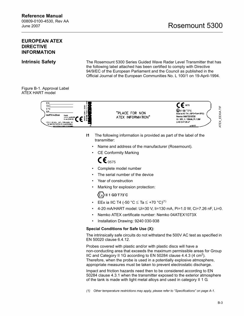
Reference Manual 00809-0100-4530, Rev AAJune 2007 Rosemount 5300
EUROPEAN ATEX DIRECTIVE INFORMATION
Intrinsic Safety The Rosemount 5300 Series Guided Wave Radar Level Transmitter that has the following label attached has been certified to comply with Directive 94/9/EC of the European Parliament and the Council as published in the Official Journal of the European Communities No. L 100/1 on 19-April-1994.
Figure B-1. Approval Label ATEX HART model
I1 The following information is provided as part of the label of the transmitter:
� Name and address of the manufacturer (Rosemount).� CE Conformity Marking
� Complete model number� The serial number of the device� Year of construction� Marking for explosion protection:
� EEx ia IIC T4 (-50 °C ≤ Ta ≤ +70 °C)(1)
� 4-20 mA/HART model: Ui=30 V, Ii=130 mA, Pi=1.0 W, Ci=7.26 nF, Li=0.� Nemko ATEX certificate number: Nemko 04ATEX1073X� Installation Drawing: 9240 030-938
Special Conditions for Safe Use (X):The intrinsically safe circuits do not withstand the 500V AC test as specified in EN 50020 clause 6.4.12.
Probes covered with plastic and/or with plastic discs will have a non-conducting area that exceeds the maximum permissible areas for Group IIC and Category II 1G according to EN 50284 clause 4.4.3 (4 cm2). Therefore, when the probe is used in a potentially explosive atmosphere, appropriate measures must be taken to prevent electrostatic discharge.Impact and friction hazards need then to be considered according to EN 50284 clause 4.3.1 when the transmitter exposed to the exterior atmosphere of the tank is made with light metal alloys and used in category II 1 G.
ATEX
_EEX
IA.T
IF
(1) Other temperature restrictions may apply, please refer to �Specifications� on page A-1.
B-3
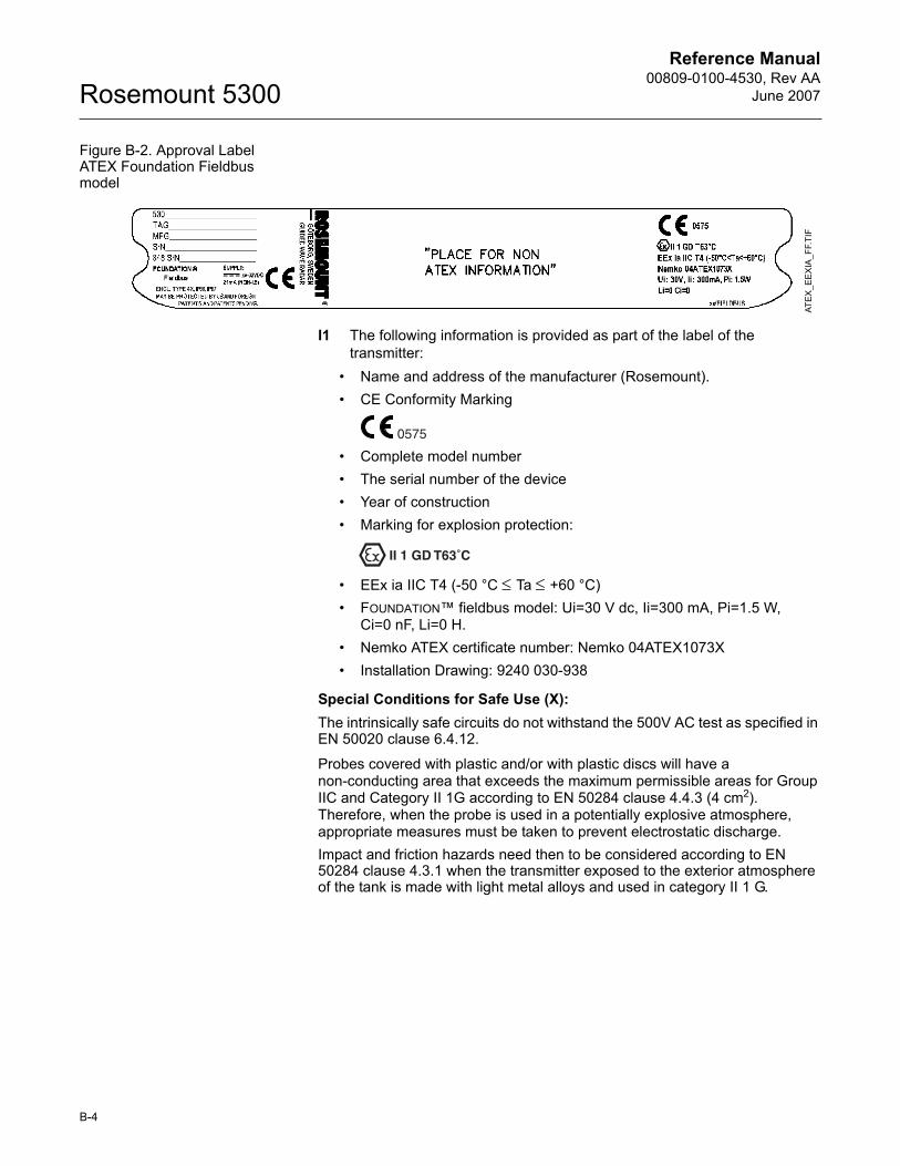
Reference Manual00809-0100-4530, Rev AA
June 2007Rosemount 5300
Figure B-2. Approval Label ATEX Foundation Fieldbus model
I1 The following information is provided as part of the label of the transmitter:
� Name and address of the manufacturer (Rosemount).� CE Conformity Marking
� Complete model number� The serial number of the device� Year of construction� Marking for explosion protection:
� EEx ia IIC T4 (-50 °C ≤ Ta ≤ +60 °C)� FOUNDATION� fieldbus model: Ui=30 V dc, Ii=300 mA, Pi=1.5 W,
Ci=0 nF, Li=0 H.� Nemko ATEX certificate number: Nemko 04ATEX1073X� Installation Drawing: 9240 030-938
Special Conditions for Safe Use (X):The intrinsically safe circuits do not withstand the 500V AC test as specified in EN 50020 clause 6.4.12.
Probes covered with plastic and/or with plastic discs will have a non-conducting area that exceeds the maximum permissible areas for Group IIC and Category II 1G according to EN 50284 clause 4.4.3 (4 cm2). Therefore, when the probe is used in a potentially explosive atmosphere, appropriate measures must be taken to prevent electrostatic discharge.Impact and friction hazards need then to be considered according to EN 50284 clause 4.3.1 when the transmitter exposed to the exterior atmosphere of the tank is made with light metal alloys and used in category II 1 G.
ATEX
_EE
XIA
_FF.
TIF
B-4
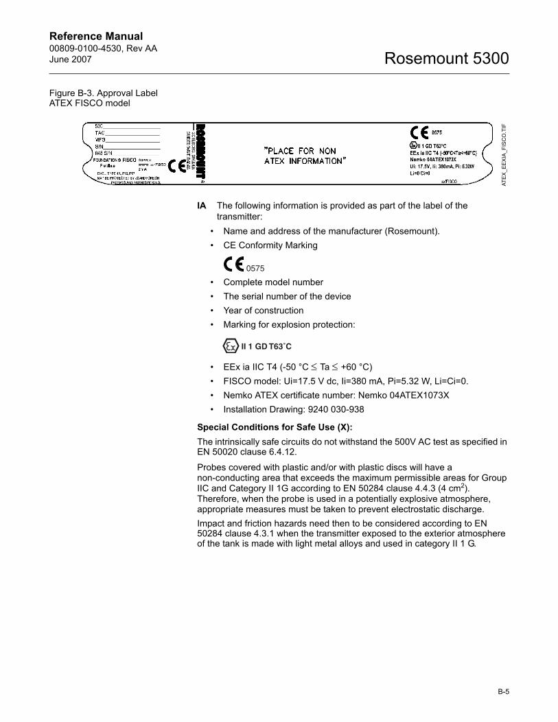
Reference Manual 00809-0100-4530, Rev AAJune 2007 Rosemount 5300
Figure B-3. Approval Label ATEX FISCO model
IA The following information is provided as part of the label of the transmitter:
� Name and address of the manufacturer (Rosemount).� CE Conformity Marking
� Complete model number� The serial number of the device� Year of construction� Marking for explosion protection:
� EEx ia IIC T4 (-50 °C ≤ Ta ≤ +60 °C)� FISCO model: Ui=17.5 V dc, Ii=380 mA, Pi=5.32 W, Li=Ci=0.� Nemko ATEX certificate number: Nemko 04ATEX1073X� Installation Drawing: 9240 030-938
Special Conditions for Safe Use (X):The intrinsically safe circuits do not withstand the 500V AC test as specified in EN 50020 clause 6.4.12.
Probes covered with plastic and/or with plastic discs will have a non-conducting area that exceeds the maximum permissible areas for Group IIC and Category II 1G according to EN 50284 clause 4.4.3 (4 cm2). Therefore, when the probe is used in a potentially explosive atmosphere, appropriate measures must be taken to prevent electrostatic discharge.Impact and friction hazards need then to be considered according to EN 50284 clause 4.3.1 when the transmitter exposed to the exterior atmosphere of the tank is made with light metal alloys and used in category II 1 G.
ATE
X_E
EXIA
_FIS
CO
.TIF
B-5
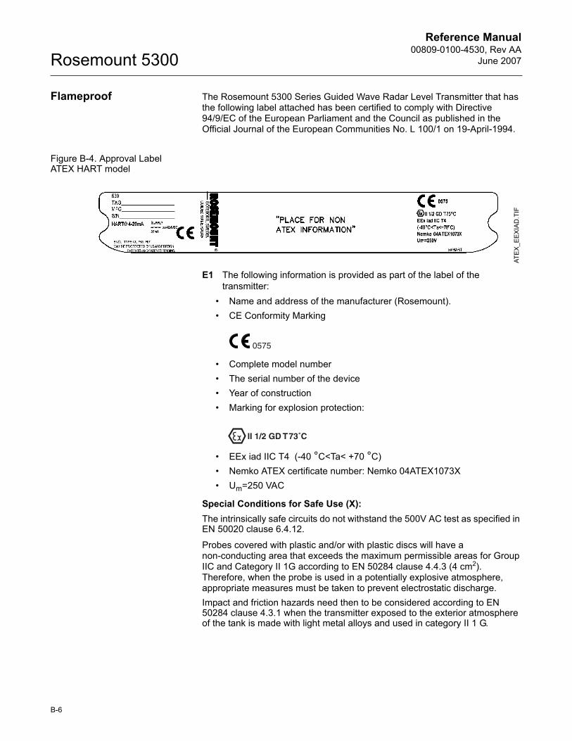
Reference Manual00809-0100-4530, Rev AA
June 2007Rosemount 5300
Flameproof The Rosemount 5300 Series Guided Wave Radar Level Transmitter that has the following label attached has been certified to comply with Directive 94/9/EC of the European Parliament and the Council as published in the Official Journal of the European Communities No. L 100/1 on 19-April-1994.
Figure B-4. Approval Label ATEX HART model
E1 The following information is provided as part of the label of the transmitter:
� Name and address of the manufacturer (Rosemount).� CE Conformity Marking
� Complete model number� The serial number of the device� Year of construction� Marking for explosion protection:
� EEx iad IIC T4 (-40 °C<Ta< +70 °C)� Nemko ATEX certificate number: Nemko 04ATEX1073X� Um=250 VAC
Special Conditions for Safe Use (X):The intrinsically safe circuits do not withstand the 500V AC test as specified in EN 50020 clause 6.4.12.
Probes covered with plastic and/or with plastic discs will have a non-conducting area that exceeds the maximum permissible areas for Group IIC and Category II 1G according to EN 50284 clause 4.4.3 (4 cm2). Therefore, when the probe is used in a potentially explosive atmosphere, appropriate measures must be taken to prevent electrostatic discharge.Impact and friction hazards need then to be considered according to EN 50284 clause 4.3.1 when the transmitter exposed to the exterior atmosphere of the tank is made with light metal alloys and used in category II 1 G.
ATE
X_E
EXIA
D.T
IF
B-6
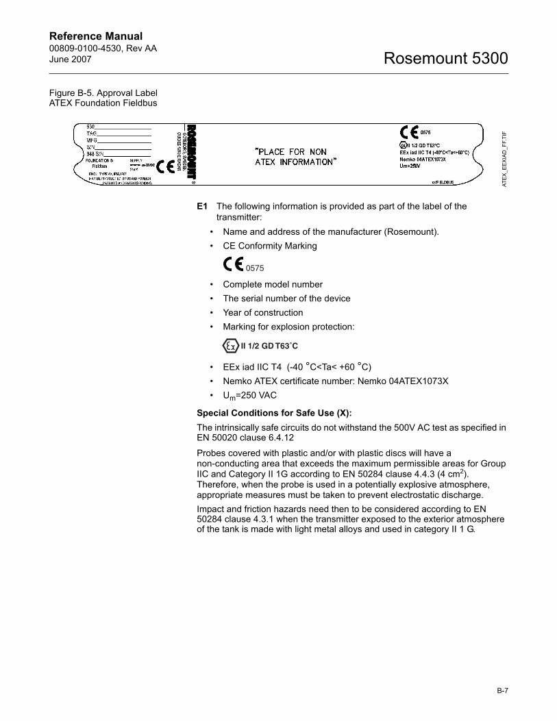
Reference Manual 00809-0100-4530, Rev AAJune 2007 Rosemount 5300
Figure B-5. Approval Label ATEX Foundation Fieldbus
E1 The following information is provided as part of the label of the transmitter:
� Name and address of the manufacturer (Rosemount).� CE Conformity Marking
� Complete model number� The serial number of the device� Year of construction� Marking for explosion protection:
� EEx iad IIC T4 (-40 °C<Ta< +60 °C)� Nemko ATEX certificate number: Nemko 04ATEX1073X� Um=250 VAC
Special Conditions for Safe Use (X):The intrinsically safe circuits do not withstand the 500V AC test as specified in EN 50020 clause 6.4.12
Probes covered with plastic and/or with plastic discs will have a non-conducting area that exceeds the maximum permissible areas for Group IIC and Category II 1G according to EN 50284 clause 4.4.3 (4 cm2). Therefore, when the probe is used in a potentially explosive atmosphere, appropriate measures must be taken to prevent electrostatic discharge.Impact and friction hazards need then to be considered according to EN 50284 clause 4.3.1 when the transmitter exposed to the exterior atmosphere of the tank is made with light metal alloys and used in category II 1 G.
ATE
X_E
EXIA
D_F
F.TI
F
B-7
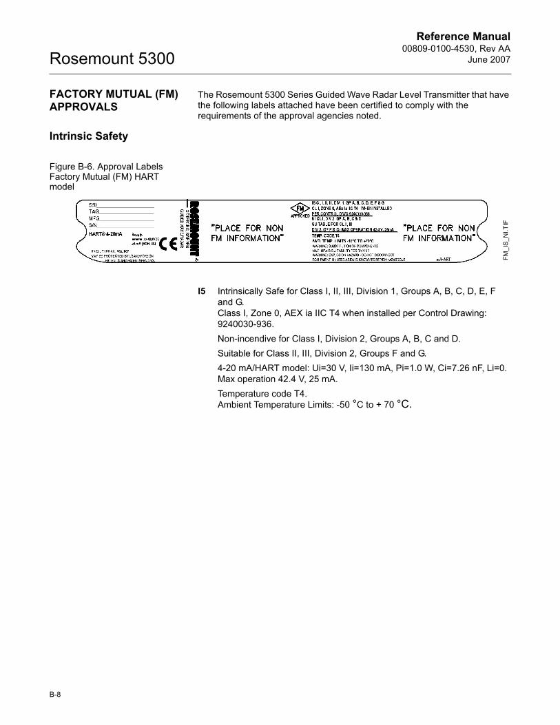
Reference Manual00809-0100-4530, Rev AA
June 2007Rosemount 5300
FACTORY MUTUAL (FM) APPROVALS
The Rosemount 5300 Series Guided Wave Radar Level Transmitter that have the following labels attached have been certified to comply with the requirements of the approval agencies noted.
Intrinsic Safety
Figure B-6. Approval Labels Factory Mutual (FM) HART model
I5 Intrinsically Safe for Class I, II, III, Division 1, Groups A, B, C, D, E, Fand G. Class I, Zone 0, AEX ia IIC T4 when installed per Control Drawing: 9240030-936.Non-incendive for Class I, Division 2, Groups A, B, C and D.Suitable for Class II, III, Division 2, Groups F and G.4-20 mA/HART model: Ui=30 V, Ii=130 mA, Pi=1.0 W, Ci=7.26 nF, Li=0.Max operation 42.4 V, 25 mA.Temperature code T4.Ambient Temperature Limits: -50 °C to + 70 °C.
FM_I
S_N
I.TIF
B-8
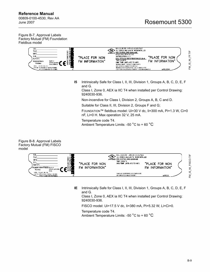
Reference Manual 00809-0100-4530, Rev AAJune 2007 Rosemount 5300
Figure B-7. Approval Labels Factory Mutual (FM) Foundation Fieldbus model
I5 Intrinsically Safe for Class I, II, III, Division 1, Groups A, B, C, D, E, Fand G. Class I, Zone 0, AEX ia IIC T4 when installed per Control Drawing: 9240030-936.Non-incendive for Class I, Division 2, Groups A, B, C and D.Suitable for Class II, III, Division 2, Groups F and G; FOUNDATION� fieldbus model: Ui=30 V dc, Ii=300 mA, Pi=1.3 W, Ci=0 nF, Li=0 H. Max operation 32 V, 25 mA.Temperature code T4.Ambient Temperature Limits: -50 °C to + 60 °C
Figure B-8. Approval Labels Factory Mutual (FM) FISCO model
IE Intrinsically Safe for Class I, II, III, Division 1, Groups A, B, C, D, E, Fand G. Class I, Zone 0, AEX ia IIC T4 when installed per Control Drawing: 9240030-936.FISCO model: Ui=17.5 V dc, Ii=380 mA, Pi=5.32 W, Li=Ci=0.Temperature code T4.Ambient Temperature Limits: -50 °C to + 60 °C
FM_I
S_N
I_FF
.TIF
FM_I
S_N
I_FI
SCO
.TIF
B-9
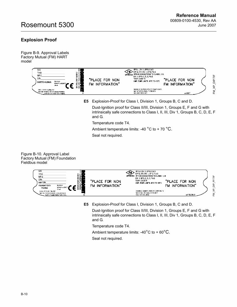
Reference Manual00809-0100-4530, Rev AA
June 2007Rosemount 5300
Explosion Proof
Figure B-9. Approval Labels Factory Mutual (FM) HART model
E5 Explosion-Proof for Class I, Division 1, Groups B, C and D.Dust-Ignition proof for Class II/III, Division 1, Groups E, F and G with intrinsically safe connections to Class I, II, III, Div 1, Groups B, C, D, E, F and G. Temperature code T4.Ambient temperature limits: -40 °C to + 70 °C.Seal not required.
Figure B-10. Approval Label Factory Mutual (FM) Foundation Fieldbus model
E5 Explosion-Proof for Class I, Division 1, Groups B, C and D.Dust-Ignition proof for Class II/III, Division 1, Groups E, F and G with intrinsically safe connections to Class I, II, III, Div 1, Groups B, C, D, E, F and G. Temperature code T4.Ambient temperature limits: -40°C to + 60°C.Seal not required.
FM_X
P_D
IP.T
IFFM
_XP
_DIP
_FF.
TIF
B-10
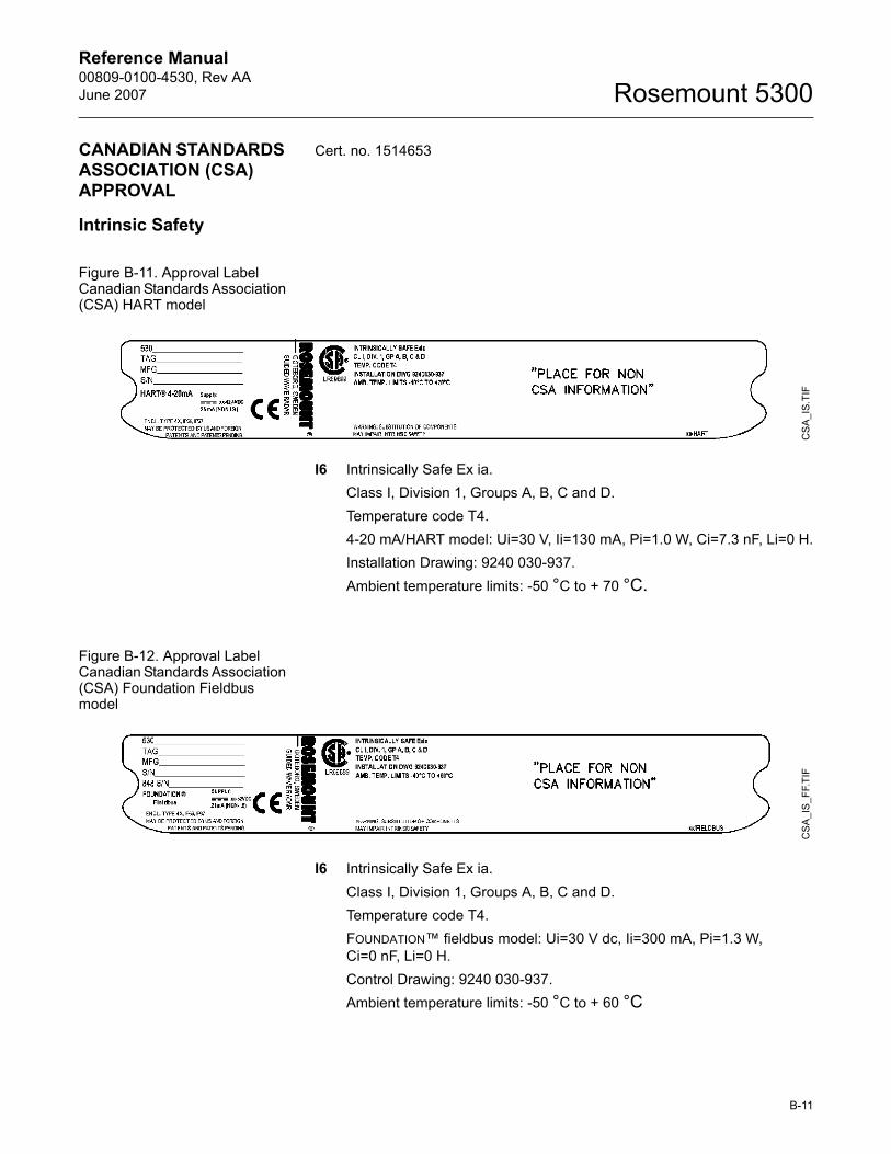
Reference Manual 00809-0100-4530, Rev AAJune 2007 Rosemount 5300
CANADIAN STANDARDS ASSOCIATION (CSA) APPROVAL
Cert. no. 1514653
Intrinsic Safety
Figure B-11. Approval Label Canadian Standards Association (CSA) HART model
I6 Intrinsically Safe Ex ia. Class I, Division 1, Groups A, B, C and D.Temperature code T4.4-20 mA/HART model: Ui=30 V, Ii=130 mA, Pi=1.0 W, Ci=7.3 nF, Li=0 H.Installation Drawing: 9240 030-937.Ambient temperature limits: -50 °C to + 70 °C.
Figure B-12. Approval Label Canadian Standards Association (CSA) Foundation Fieldbus model
I6 Intrinsically Safe Ex ia. Class I, Division 1, Groups A, B, C and D.Temperature code T4.FOUNDATION� fieldbus model: Ui=30 V dc, Ii=300 mA, Pi=1.3 W, Ci=0 nF, Li=0 H.Control Drawing: 9240 030-937.Ambient temperature limits: -50 °C to + 60 °C
CS
A_I
S.TI
FC
SA
_IS
_FF.
TIF
B-11
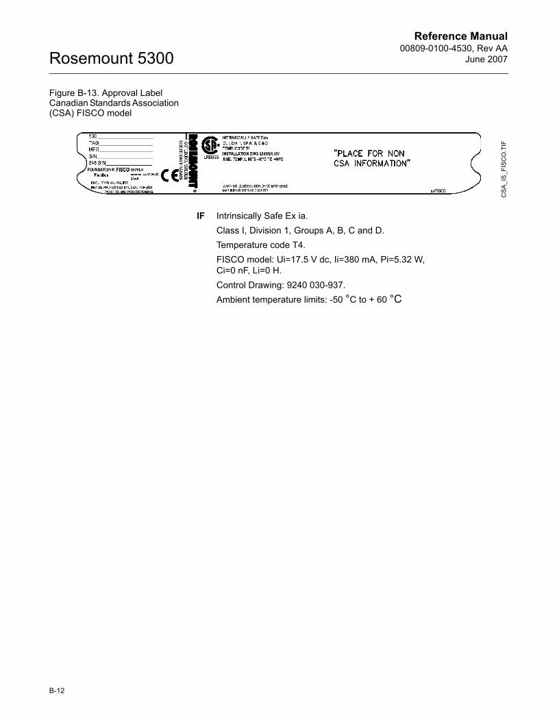
Reference Manual00809-0100-4530, Rev AA
June 2007Rosemount 5300
Figure B-13. Approval Label Canadian Standards Association (CSA) FISCO model
IF Intrinsically Safe Ex ia. Class I, Division 1, Groups A, B, C and D.Temperature code T4.FISCO model: Ui=17.5 V dc, Ii=380 mA, Pi=5.32 W, Ci=0 nF, Li=0 H.Control Drawing: 9240 030-937.Ambient temperature limits: -50 °C to + 60 °C
CS
A_I
S_F
ISC
O.T
IF
B-12
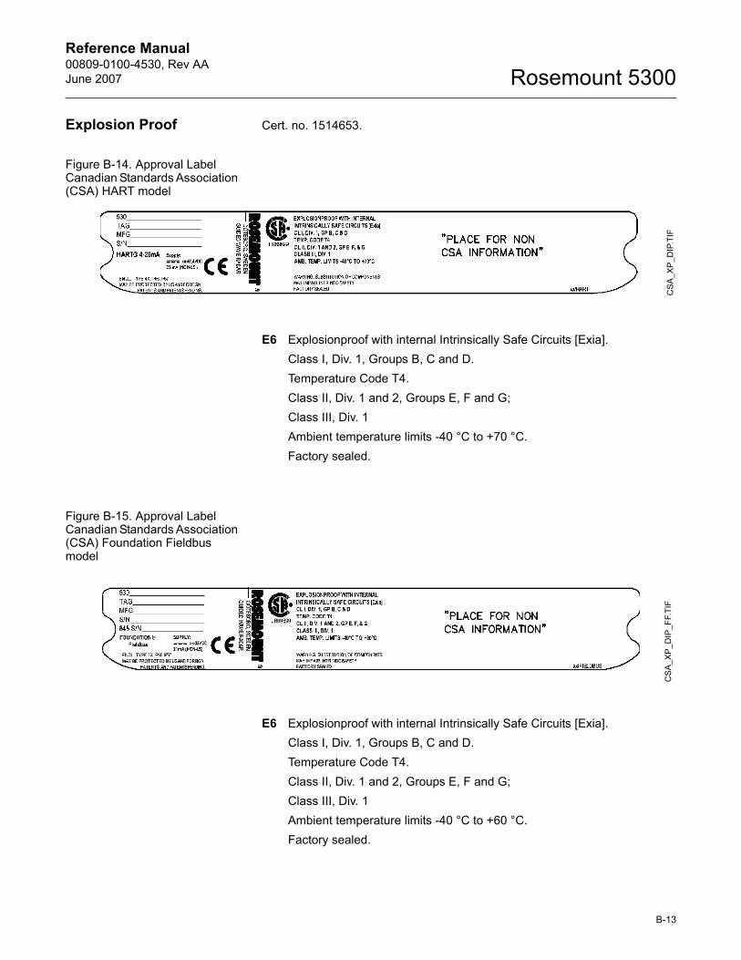
Reference Manual 00809-0100-4530, Rev AAJune 2007 Rosemount 5300
Explosion Proof Cert. no. 1514653.
Figure B-14. Approval Label Canadian Standards Association (CSA) HART model
E6 Explosionproof with internal Intrinsically Safe Circuits [Exia].Class I, Div. 1, Groups B, C and D.Temperature Code T4.Class II, Div. 1 and 2, Groups E, F and G;Class III, Div. 1Ambient temperature limits -40 °C to +70 °C.Factory sealed.
Figure B-15. Approval Label Canadian Standards Association (CSA) Foundation Fieldbus model
E6 Explosionproof with internal Intrinsically Safe Circuits [Exia].Class I, Div. 1, Groups B, C and D.Temperature Code T4.Class II, Div. 1 and 2, Groups E, F and G;Class III, Div. 1Ambient temperature limits -40 °C to +60 °C.Factory sealed.
CS
A_X
P_D
IP.T
IFC
SA_
XP_
DIP
_FF.
TIF
B-13
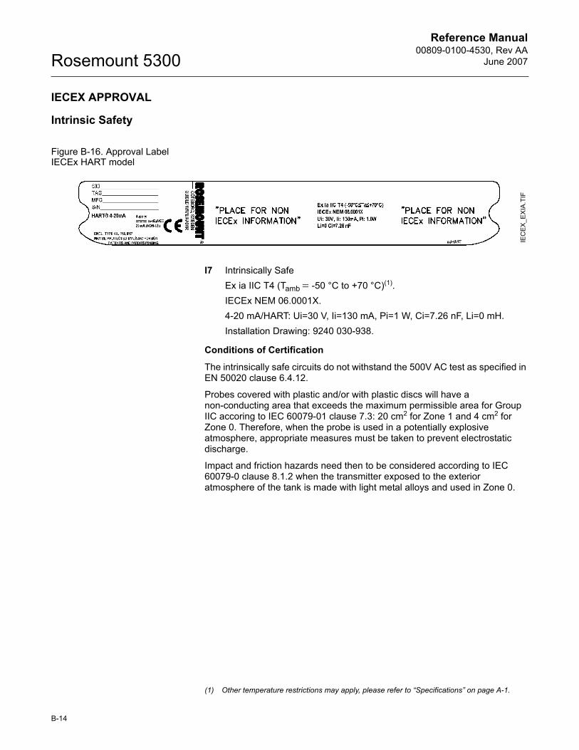
Reference Manual00809-0100-4530, Rev AA
June 2007Rosemount 5300
IECEX APPROVAL
Intrinsic Safety
Figure B-16. Approval Label IECEx HART model
I7 Intrinsically SafeEx ia IIC T4 (Tamb = -50 °C to +70 °C)(1).IECEx NEM 06.0001X.4-20 mA/HART: Ui=30 V, Ii=130 mA, Pi=1 W, Ci=7.26 nF, Li=0 mH.Installation Drawing: 9240 030-938.
Conditions of Certification
The intrinsically safe circuits do not withstand the 500V AC test as specified in EN 50020 clause 6.4.12.
Probes covered with plastic and/or with plastic discs will have a non-conducting area that exceeds the maximum permissible area for Group IIC accoring to IEC 60079-01 clause 7.3: 20 cm2 for Zone 1 and 4 cm2 for Zone 0. Therefore, when the probe is used in a potentially explosive atmosphere, appropriate measures must be taken to prevent electrostatic discharge.
Impact and friction hazards need then to be considered according to IEC 60079-0 clause 8.1.2 when the transmitter exposed to the exterior atmosphere of the tank is made with light metal alloys and used in Zone 0.
IEC
EX
_EX
IA.T
IF
(1) Other temperature restrictions may apply, please refer to �Specifications� on page A-1.
B-14
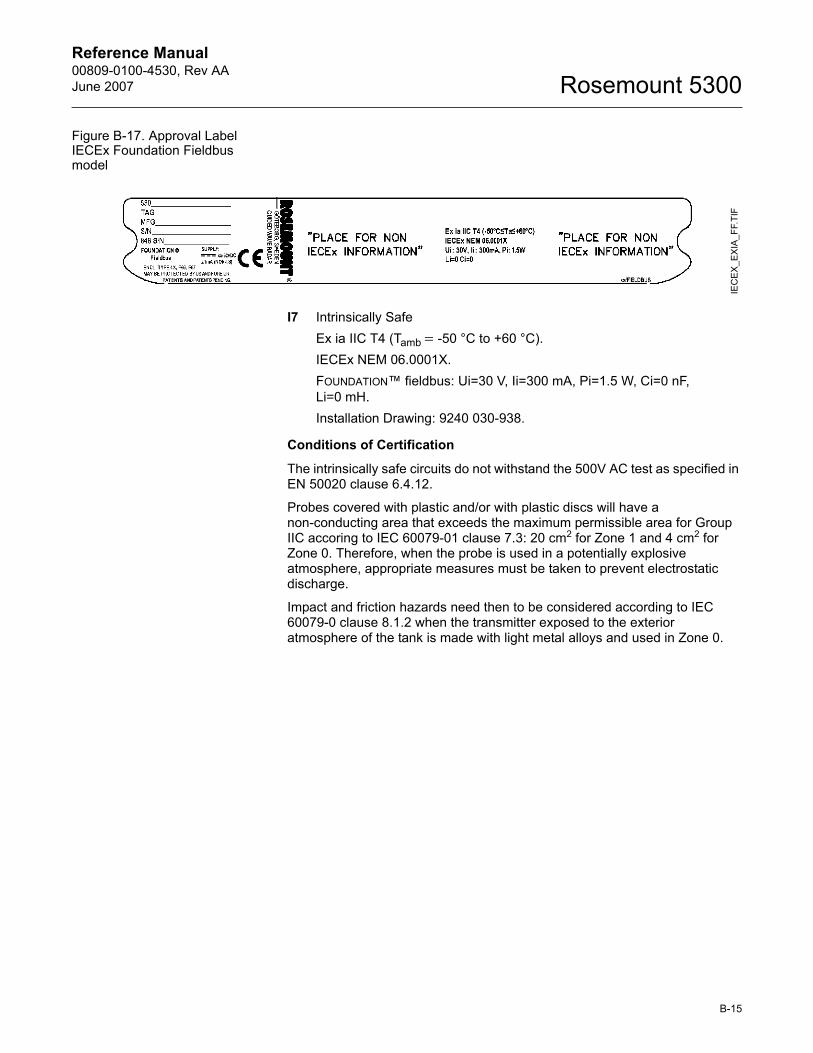
Reference Manual 00809-0100-4530, Rev AAJune 2007 Rosemount 5300
Figure B-17. Approval Label IECEx Foundation Fieldbus model
I7 Intrinsically SafeEx ia IIC T4 (Tamb = -50 °C to +60 °C).IECEx NEM 06.0001X.FOUNDATION� fieldbus: Ui=30 V, Ii=300 mA, Pi=1.5 W, Ci=0 nF, Li=0 mH.Installation Drawing: 9240 030-938.
Conditions of Certification
The intrinsically safe circuits do not withstand the 500V AC test as specified in EN 50020 clause 6.4.12.
Probes covered with plastic and/or with plastic discs will have a non-conducting area that exceeds the maximum permissible area for Group IIC accoring to IEC 60079-01 clause 7.3: 20 cm2 for Zone 1 and 4 cm2 for Zone 0. Therefore, when the probe is used in a potentially explosive atmosphere, appropriate measures must be taken to prevent electrostatic discharge.
Impact and friction hazards need then to be considered according to IEC 60079-0 clause 8.1.2 when the transmitter exposed to the exterior atmosphere of the tank is made with light metal alloys and used in Zone 0.
IEC
EX
_EX
IA_F
F.TI
F
B-15
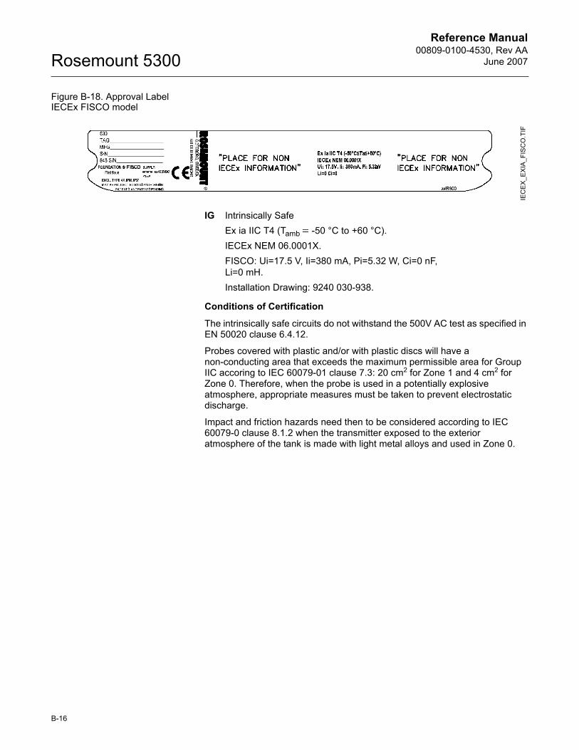
Reference Manual00809-0100-4530, Rev AA
June 2007Rosemount 5300
Figure B-18. Approval Label IECEx FISCO model
IG Intrinsically SafeEx ia IIC T4 (Tamb = -50 °C to +60 °C).IECEx NEM 06.0001X.FISCO: Ui=17.5 V, Ii=380 mA, Pi=5.32 W, Ci=0 nF, Li=0 mH.Installation Drawing: 9240 030-938.
Conditions of Certification
The intrinsically safe circuits do not withstand the 500V AC test as specified in EN 50020 clause 6.4.12.
Probes covered with plastic and/or with plastic discs will have a non-conducting area that exceeds the maximum permissible area for Group IIC accoring to IEC 60079-01 clause 7.3: 20 cm2 for Zone 1 and 4 cm2 for Zone 0. Therefore, when the probe is used in a potentially explosive atmosphere, appropriate measures must be taken to prevent electrostatic discharge.
Impact and friction hazards need then to be considered according to IEC 60079-0 clause 8.1.2 when the transmitter exposed to the exterior atmosphere of the tank is made with light metal alloys and used in Zone 0.
IEC
EX
_EX
IA_F
ISC
O.T
IF
B-16
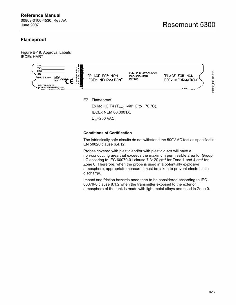
Reference Manual 00809-0100-4530, Rev AAJune 2007 Rosemount 5300
Flameproof
Figure B-19. Approval Labels IECEx HART
E7 FlameproofEx iad IIC T4 (Tamb :-40° C to +70 °C).IECEx NEM 06.0001X.Um=250 VAC
Conditions of Certification
The intrinsically safe circuits do not withstand the 500V AC test as specified in EN 50020 clause 6.4.12.
Probes covered with plastic and/or with plastic discs will have a non-conducting area that exceeds the maximum permissible area for Group IIC accoring to IEC 60079-01 clause 7.3: 20 cm2 for Zone 1 and 4 cm2 for Zone 0. Therefore, when the probe is used in a potentially explosive atmosphere, appropriate measures must be taken to prevent electrostatic discharge.
Impact and friction hazards need then to be considered according to IEC 60079-0 clause 8.1.2 when the transmitter exposed to the exterior atmosphere of the tank is made with light metal alloys and used in Zone 0.
IEC
EX
_EX
IAD
.TIF
B-17
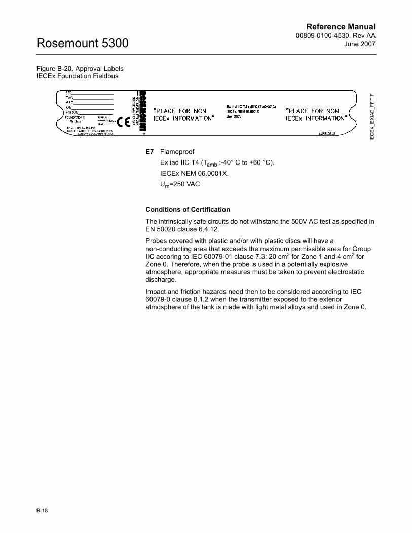
Reference Manual00809-0100-4530, Rev AA
June 2007Rosemount 5300
Figure B-20. Approval Labels IECEx Foundation Fieldbus
E7 FlameproofEx iad IIC T4 (Tamb :-40° C to +60 °C).IECEx NEM 06.0001X.Um=250 VAC
Conditions of Certification
The intrinsically safe circuits do not withstand the 500V AC test as specified in EN 50020 clause 6.4.12.
Probes covered with plastic and/or with plastic discs will have a non-conducting area that exceeds the maximum permissible area for Group IIC accoring to IEC 60079-01 clause 7.3: 20 cm2 for Zone 1 and 4 cm2 for Zone 0. Therefore, when the probe is used in a potentially explosive atmosphere, appropriate measures must be taken to prevent electrostatic discharge.
Impact and friction hazards need then to be considered according to IEC 60079-0 clause 8.1.2 when the transmitter exposed to the exterior atmosphere of the tank is made with light metal alloys and used in Zone 0.
IEC
EX
_EXI
AD_F
F.TI
F
B-18
Reference Manual 00809-0100-4530, Rev AAJune 2007 Rosemount 5300
COMBINATION APPROVALS
KA ATEX, FM, CSA Flameproof/ExplosionproofKB ATEX, FM, IECEx Flameproof/ExplosionproofKC ATEX, CSA, IECEx Flameproof/ExplosionproofKD FM, CSA, IECEx Flameproof/ExplosionproofKE ATEX, FM, CSA Intrinsic SafetyKF ATEX, FM, IECEx Intrinsic SafetyKG ATEX, CSA, IECEx Intrinsic SafetyKH FM, CSA, IECEx Intrinsic SafetyKI FISCO - ATEX, FM, CSA Intrinsic SafetyKJ FISCO - ATEX, FM, IECEX Intrinsic SafetyKK FISCO - ATEX, CSA, IECEX Intrinsic SafetyKL FISCO - FM, CSA, IECEX Intrinsic Safety
APPROVAL DRAWINGS This section contains FM Approvals System Control Drawing and Canadian Standards Association and IECEx/ATEX Installation Drawings. You must follow the installation guidelines presented in order to maintain certified ratings for installed transmitters.
This section contains the following drawings:
Rosemount drawing 9240030-936:
System Control Drawing for hazardous location installation of intrinsically safe FM approved apparatus.
Rosemount drawing 9240030-937:
Installation Drawing for hazardous location installation of CSA approved apparatus.
Rosemount drawing 9240030-938:
Installation Drawing for hazardous location installation of ATEX and IECEx approved apparatus.
B-19
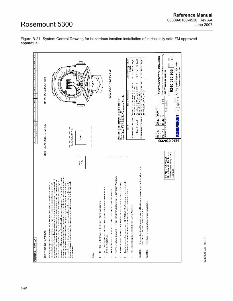
Reference Manual00809-0100-4530, Rev AA
June 2007Rosemount 5300
Figure B-21. System Control Drawing for hazardous location installation of intrinsically safe FM approved apparatus.
9240
030-
936_
I01.
TIF
B-20
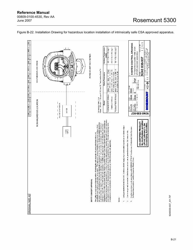
Reference Manual 00809-0100-4530, Rev AAJune 2007 Rosemount 5300
Figure B-22. Installation Drawing for hazardous location installation of intrinsically safe CSA approved apparatus.
9240
030-
937_
I01.
TIF
B-21
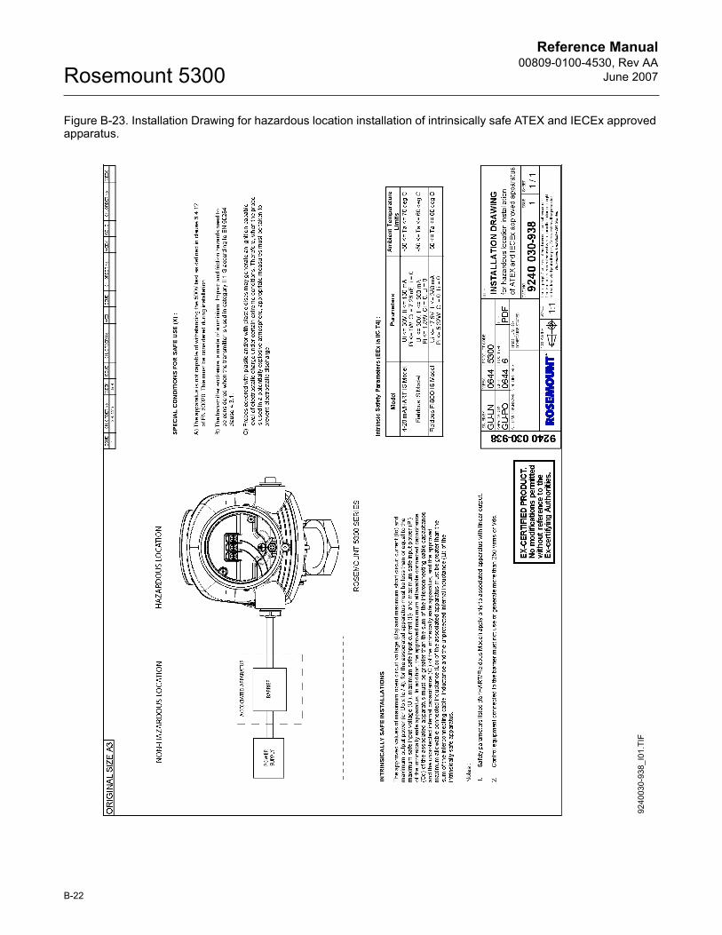
Reference Manual00809-0100-4530, Rev AA
June 2007Rosemount 5300
Figure B-23. Installation Drawing for hazardous location installation of intrinsically safe ATEX and IECEx approved apparatus.
9240
030-
938_
I01.
TIF
B-22
Reference Manual 00809-0100-4530, Rev AAJune 2007 Rosemount 5300
Appendix C Advanced Configuration
Safety messages . . . . . . . . . . . . . . . . . . . . . . . . . . . . . . . . . page C-1User defined Upper Reference Point . . . . . . . . . . . . . . . . page C-3Handling of Disturbances from Nozzle . . . . . . . . . . . . . . . page C-4Threshold Settings . . . . . . . . . . . . . . . . . . . . . . . . . . . . . . . page C-6Probe End Projection . . . . . . . . . . . . . . . . . . . . . . . . . . . . . page C-8Dielectric Constant Settings . . . . . . . . . . . . . . . . . . . . . . . page C-10
SAFETY MESSAGES Procedures and instructions in this section may require special precautions to ensure the safety of the personnel performing the operations. Information that raises potential safety issues is indicated by a warning symbol ( ). Please refer to the following safety messages before performing an operation preceded by this symbol.
Explosions could result in death or serious injury:Verify that the operating environment of the transmitter is consistent with the appropriate hazardous locations certifications.
Before connecting a HART-based communicator in an explosive atmosphere, make sure the instruments in the loop are installed in accordance with intrinsically safe or non-incendive field wiring practices.
Do not remove the transmitter cover in explosive atmospheres when the circuit is alive.
Failure to follow safe installation and servicing guidelines could result in death or serious injury:Make sure the transmitter is installed by qualified personnel and in accordance with applicable code of practice.
Use the equipment only as specified in this manual. Failure to do so may impair the protection provided by the equipment.
Do not perform any service other than those contained in this manual unless you are qualified.
Any substitution of non-recognized spare parts may jeopardize safety. Repair, for e.g. substitution of components etc. may also jeopardize safety and is under no circumstances allowed.
To prevent ignition of flammable or combustible atmospheres, disconnect power before servicing.
www.rosemount.com
Reference Manual00809-0100-4530, Rev AA
June 2007Rosemount 5300
High voltage that may be present on leads could cause electrical shock:Avoid contact with leads and terminals.
Make sure the mains power to the Radar Transmitter is off and the lines to any other external power source are disconnected or not powered while wiringthe transmitter.
Probes covered with plastic and/or with plastic discs may generate an ignition-capable level of electrostatic charge under certain extreme conditions. Therefore, when the probe is used in a potentially explosive atmosphere, appropriate measures must be taken to prevent electrostatic discharge.
C-2
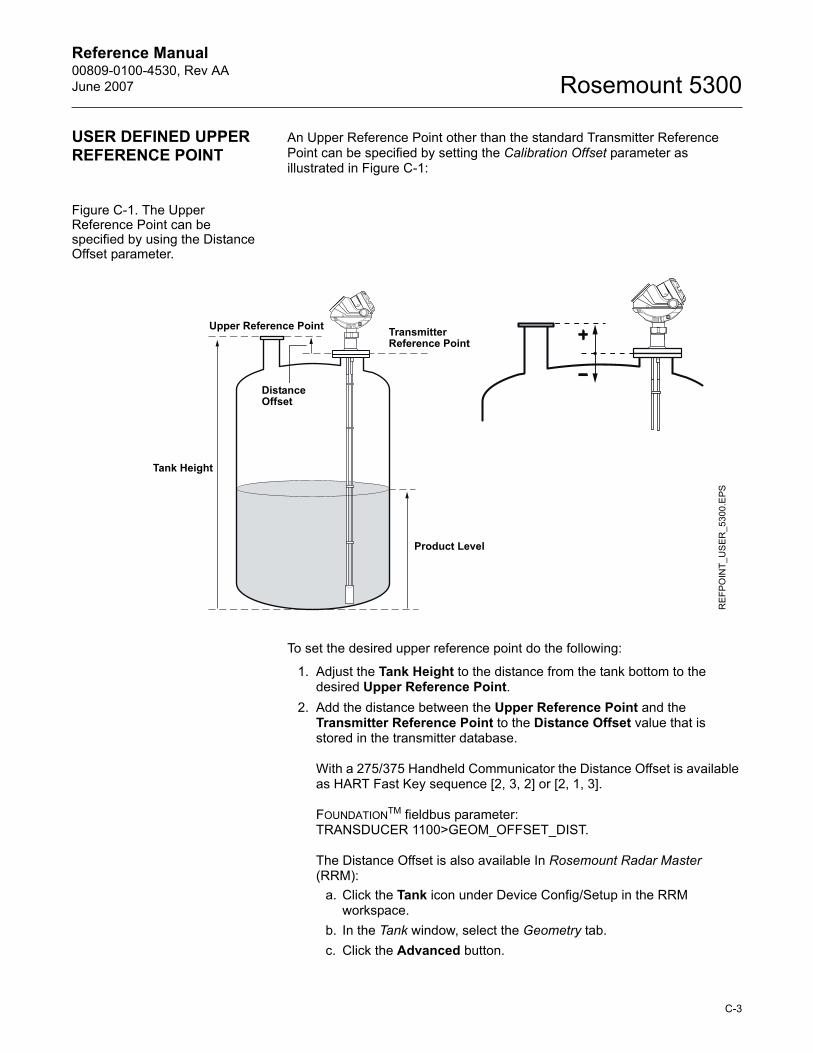
Reference Manual 00809-0100-4530, Rev AAJune 2007 Rosemount 5300
USER DEFINED UPPER REFERENCE POINT
An Upper Reference Point other than the standard Transmitter Reference Point can be specified by setting the Calibration Offset parameter as illustrated in Figure C-1:
Figure C-1. The Upper Reference Point can be specified by using the Distance Offset parameter.
To set the desired upper reference point do the following:
1. Adjust the Tank Height to the distance from the tank bottom to the desired Upper Reference Point.
2. Add the distance between the Upper Reference Point and the Transmitter Reference Point to the Distance Offset value that is stored in the transmitter database.
With a 275/375 Handheld Communicator the Distance Offset is available as HART Fast Key sequence [2, 3, 2] or [2, 1, 3].
FOUNDATIONTM fieldbus parameter: TRANSDUCER 1100>GEOM_OFFSET_DIST.
The Distance Offset is also available In Rosemount Radar Master (RRM):
a. Click the Tank icon under Device Config/Setup in the RRM workspace.
b. In the Tank window, select the Geometry tab.c. Click the Advanced button.
Tank Height
Product Level
Upper Reference Point Transmitter Reference Point
Distance Offset
REF
PO
INT_
US
ER
_530
0.E
PS
C-3
Reference Manual00809-0100-4530, Rev AA
June 2007Rosemount 5300
HANDLING OF DISTURBANCES FROM NOZZLE
Using the Trim Near Zone Function
For transmitters using the Guided Wave Radar technology the performance In the Near Zone (referred to as the region between 0-10 in. (0-0.25 m) below the Upper Reference Point) is normally somewhat limited. However, the 5300 transmitter is equipped with software functionality that minimizes the Upper Transition Zone. The factory setting is normally sufficient and doesn�t need to be repeated after installation.
However, since the setting is optimized depending on actual installation, further trimming may be necessary in the case of unfavorable conditions. This may for example be the case if a Single Lead probe is mounted in a small nozzle, or if there are disturbing obstacles in the Near Zone. The trimming means that the measurement performance in the Near Zone is maintained even under these conditions and prevents false echo indication.
Make sure that the product level is below the Near Zone region (0-1.6 ft. (0-0.5 m) below the Upper Reference Point).
To trim the Near Zone performance with a 375 Field Communicator do the following:
1. Select the HART command [2, 6, 3].2. Select the Trim Near Zone option.
To trim the Near Zone performance by using the Rosemount Radar Master (RRM) do the following:
1. Start the RRM.2. Click the Advanced icon in the Device Config/Setup toolbar.3. Select the Near Zone tab in the Advanced Configuration window.4. Click the Trim Near Zone button.
NOTE!The Trim Near Zone function should only be used for reducing impact from stationary disturbances. It is not suitable for occasional disturbances.
To reset the transmitter to factory settings by using the Rosemount Radar Master (RRM) do the following:
1. Start the RRM.2. From the Tools menu, choose the Factory Settings option.
Changing the Upper Null Zone
Measurements are not performed within the Upper Null Zone (UNZ). By setting the UNZ parameter to zero, measurements can be performed in the region close to the flange (Near Zone).
If there are measurement problems in the upper part of the tank you may use the Trim Near Zone function as described above.
If the desired measurement range is below the Near Zone, or if disturbing objects are located below the Near Zone, the Upper Null Zone parameter can be used to avoid measurements above a certain level.
C-4
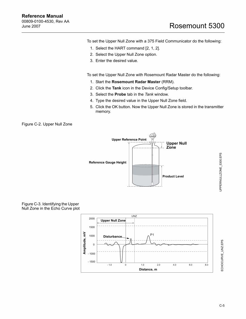
Reference Manual 00809-0100-4530, Rev AAJune 2007 Rosemount 5300
To set the Upper Null Zone with a 375 Field Communicator do the following:
1. Select the HART command [2, 1, 2].2. Select the Upper Null Zone option.3. Enter the desired value.
To set the Upper Null Zone with Rosemount Radar Master do the following:
1. Start the Rosemount Radar Master (RRM).2. Click the Tank icon in the Device Config/Setup toolbar.3. Select the Probe tab in the Tank window.4. Type the desired value in the Upper Null Zone field.5. Click the OK button. Now the Upper Null Zone is stored in the transmitter
memory.
Figure C-2. Upper Null Zone
Figure C-3. Identifying the Upper Null Zone in the Echo Curve plot
Reference Gauge Height
Upper Null Zone
Product Level
Upper Reference Point
UP
PE
RN
ULL
ZON
E_5
300.
EPS
Upper Null Zone
Disturbance
EC
HO
CU
RV
E_U
NZ.
EPS
Am
plitu
de, m
V
Distance, m
C-5
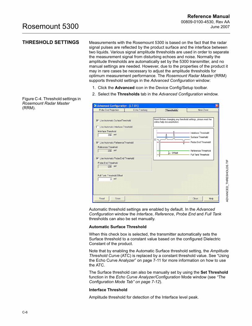
Reference Manual00809-0100-4530, Rev AA
June 2007Rosemount 5300
THRESHOLD SETTINGS Measurements with the Rosemount 5300 is based on the fact that the radar signal pulses are reflected by the product surface and the interface between two liquids. Various signal amplitude thresholds are used in order to separate the measurement signal from disturbing echoes and noise. Normally the amplitude thresholds are automatically set by the 5300 transmitter, and no manual settings are needed. However, due to the properties of the product it may in rare cases be necessary to adjust the amplitude thresholds for optimum measurement performance. The Rosemount Radar Master (RRM) supports threshold settings in the Advanced Configuration window:
1. Click the Advanced icon in the Device Config/Setup toolbar.2. Select the Thresholds tab in the Advanced Configuration window.
Figure C-4. Threshold settings in Rosemount Radar Master (RRM).
Automatic threshold settings are enabled by default. In the Advanced Configuration window the Interface, Reference, Probe End and Full Tank thresholds can also be set manually.
Automatic Surface Threshold
When this check box is selected, the transmitter automatically sets the Surface threshold to a constant value based on the configured Dielectric Constant of the product.
Note that by enabling the Automatic Surface threshold setting, the Amplitude Threshold Curve (ATC) is replaced by a constant threshold value. See �Using the Echo Curve Analyzer� on page 7-11 for more information on how to use the ATC.
The Surface threshold can also be manually set by using the Set Threshold function in the Echo Curve Analyzer/Configuration Mode window (see �The Configuration Mode Tab� on page 7-12).
Interface Threshold
Amplitude threshold for detection of the Interface level peak.
AD
VAN
CE
D_T
HR
ES
HO
LDS
.TIF
C-6
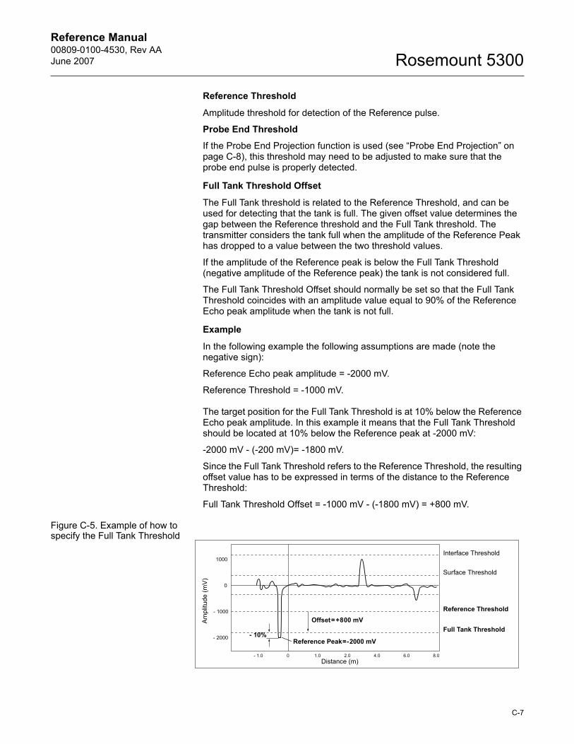
Reference Manual 00809-0100-4530, Rev AAJune 2007 Rosemount 5300
Reference Threshold
Amplitude threshold for detection of the Reference pulse.
Probe End Threshold
If the Probe End Projection function is used (see �Probe End Projection� on page C-8), this threshold may need to be adjusted to make sure that the probe end pulse is properly detected.
Full Tank Threshold Offset
The Full Tank threshold is related to the Reference Threshold, and can be used for detecting that the tank is full. The given offset value determines the gap between the Reference threshold and the Full Tank threshold. The transmitter considers the tank full when the amplitude of the Reference Peak has dropped to a value between the two threshold values.
If the amplitude of the Reference peak is below the Full Tank Threshold (negative amplitude of the Reference peak) the tank is not considered full.
The Full Tank Threshold Offset should normally be set so that the Full Tank Threshold coincides with an amplitude value equal to 90% of the Reference Echo peak amplitude when the tank is not full.
Example
In the following example the following assumptions are made (note the negative sign):
Reference Echo peak amplitude = -2000 mV.
Reference Threshold = -1000 mV.
The target position for the Full Tank Threshold is at 10% below the Reference Echo peak amplitude. In this example it means that the Full Tank Threshold should be located at 10% below the Reference peak at -2000 mV:
-2000 mV - (-200 mV)= -1800 mV.
Since the Full Tank Threshold refers to the Reference Threshold, the resulting offset value has to be expressed in terms of the distance to the Reference Threshold:
Full Tank Threshold Offset = -1000 mV - (-1800 mV) = +800 mV.
Figure C-5. Example of how to specify the Full Tank Threshold
Am
plitu
de (m
V)
Reference Threshold
Full Tank ThresholdOffset=+800 mV
- 10%Reference Peak=-2000 mV
Surface Threshold
Interface Threshold
Distance (m)
C-7
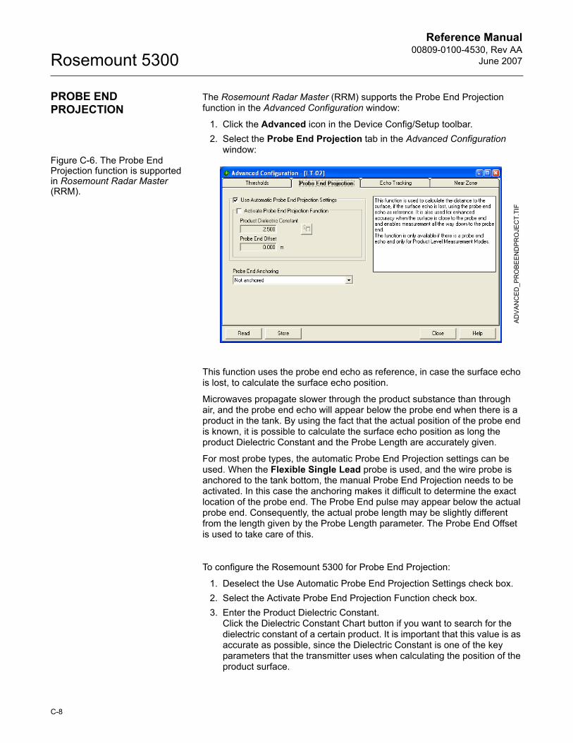
Reference Manual00809-0100-4530, Rev AA
June 2007Rosemount 5300
PROBE END PROJECTION
The Rosemount Radar Master (RRM) supports the Probe End Projection function in the Advanced Configuration window:
1. Click the Advanced icon in the Device Config/Setup toolbar.2. Select the Probe End Projection tab in the Advanced Configuration
window:Figure C-6. The Probe End Projection function is supported in Rosemount Radar Master (RRM).
This function uses the probe end echo as reference, in case the surface echo is lost, to calculate the surface echo position.
Microwaves propagate slower through the product substance than through air, and the probe end echo will appear below the probe end when there is a product in the tank. By using the fact that the actual position of the probe end is known, it is possible to calculate the surface echo position as long the product Dielectric Constant and the Probe Length are accurately given.
For most probe types, the automatic Probe End Projection settings can be used. When the Flexible Single Lead probe is used, and the wire probe is anchored to the tank bottom, the manual Probe End Projection needs to be activated. In this case the anchoring makes it difficult to determine the exact location of the probe end. The Probe End pulse may appear below the actual probe end. Consequently, the actual probe length may be slightly different from the length given by the Probe Length parameter. The Probe End Offset is used to take care of this.
To configure the Rosemount 5300 for Probe End Projection:
1. Deselect the Use Automatic Probe End Projection Settings check box.2. Select the Activate Probe End Projection Function check box.3. Enter the Product Dielectric Constant.
Click the Dielectric Constant Chart button if you want to search for the dielectric constant of a certain product. It is important that this value is as accurate as possible, since the Dielectric Constant is one of the key parameters that the transmitter uses when calculating the position of the product surface.
AD
VAN
CED
_PR
OBE
EN
DP
RO
JEC
T.TI
F
C-8
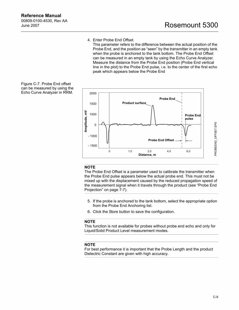
Reference Manual 00809-0100-4530, Rev AAJune 2007 Rosemount 5300
4. Enter Probe End Offset. This parameter refers to the difference between the actual position of the Probe End, and the position as �seen� by the transmitter in an empty tank when the probe is anchored to the tank bottom. The Probe End Offset can be measured in an empty tank by using the Echo Curve Analyzer. Measure the distance from the Probe End position (Probe End vertical line in the plot) to the Probe End pulse, i.e. to the center of the first echo peak which appears below the Probe End
Figure C-7. Probe End offset can be measured by using the Echo Curve Analyzer in RRM.
NOTEThe Probe End Offset is a parameter used to calibrate the transmitter when the Probe End pulse appears below the actual probe end. This must not be mixed up with the displacement caused by the reduced propagation speed of the measurement signal when it travels through the product (see �Probe End Projection� on page 7-7).
5. If the probe is anchored to the tank bottom, select the appropriate option from the Probe End Anchoring list.
6. Click the Store button to save the configuration.
NOTEThis function is not available for probes without probe end echo and only for Liquid/Solid Product Level measurement modes.
NOTEFor best performance it is important that the Probe Length and the product Dielectric Constant are given with high accuracy.
PR
OBE
EN
D_O
FFSE
T.EP
S
Product surfaceProbe End
Probe End pulse
Probe End Offset
Am
plitu
de, m
V
Distance, m
C-9
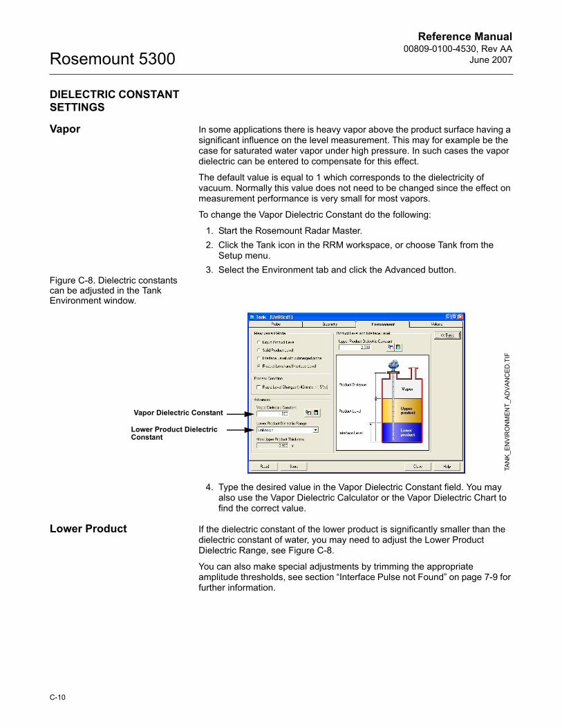
Reference Manual00809-0100-4530, Rev AA
June 2007Rosemount 5300
DIELECTRIC CONSTANT SETTINGS
Vapor In some applications there is heavy vapor above the product surface having a significant influence on the level measurement. This may for example be the case for saturated water vapor under high pressure. In such cases the vapor dielectric can be entered to compensate for this effect.
The default value is equal to 1 which corresponds to the dielectricity of vacuum. Normally this value does not need to be changed since the effect on measurement performance is very small for most vapors.
To change the Vapor Dielectric Constant do the following:
1. Start the Rosemount Radar Master.2. Click the Tank icon in the RRM workspace, or choose Tank from the
Setup menu.3. Select the Environment tab and click the Advanced button.
Figure C-8. Dielectric constants can be adjusted in the Tank Environment window.
4. Type the desired value in the Vapor Dielectric Constant field. You may also use the Vapor Dielectric Calculator or the Vapor Dielectric Chart to find the correct value.
Lower Product If the dielectric constant of the lower product is significantly smaller than the dielectric constant of water, you may need to adjust the Lower Product Dielectric Range, see Figure C-8.
You can also make special adjustments by trimming the appropriate amplitude thresholds, see section �Interface Pulse not Found� on page 7-9 for further information.
TAN
K_E
NVI
RO
NM
ENT_
AD
VAN
CED
.TIF
Vapor Dielectric Constant
Lower Product Dielectric Constant
C-10
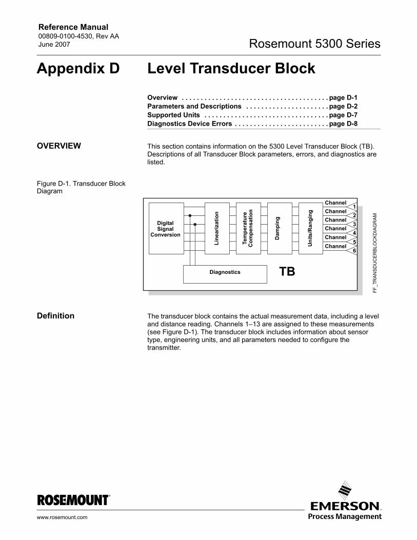
Reference Manual 00809-0100-4530, Rev AAJune 2007 Rosemount 5300 Series
Appendix D Level Transducer Block
Overview . . . . . . . . . . . . . . . . . . . . . . . . . . . . . . . . . . . . . . . page D-1Parameters and Descriptions . . . . . . . . . . . . . . . . . . . . . . page D-2Supported Units . . . . . . . . . . . . . . . . . . . . . . . . . . . . . . . . . page D-7Diagnostics Device Errors . . . . . . . . . . . . . . . . . . . . . . . . . page D-8
OVERVIEW This section contains information on the 5300 Level Transducer Block (TB). Descriptions of all Transducer Block parameters, errors, and diagnostics are listed.
Figure D-1. Transducer Block Diagram
Definition The transducer block contains the actual measurement data, including a level and distance reading. Channels 1�13 are assigned to these measurements (see Figure D-1). The transducer block includes information about sensor type, engineering units, and all parameters needed to configure the transmitter.
DigitalSignal
Conversion
Diagnostics
Line
ariz
atio
n
Tem
pera
ture
C
ompe
nsat
ion
Dam
ping
Uni
ts/R
angi
ng
Channel
FF_T
RAN
SDU
CE
RB
LOC
KD
IAG
RA
M
1
TB
23456
ChannelChannelChannelChannelChannel
www.rosemount.com
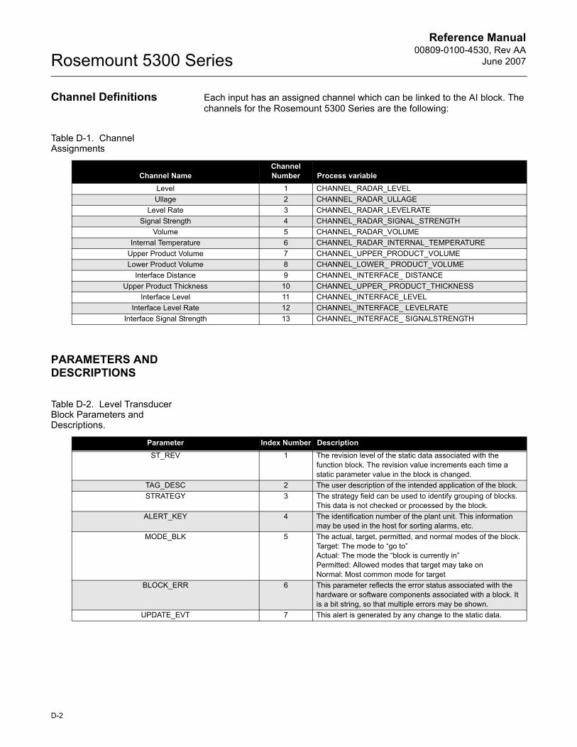
Reference Manual00809-0100-4530, Rev AA
June 2007Rosemount 5300 Series
Channel Definitions Each input has an assigned channel which can be linked to the AI block. The channels for the Rosemount 5300 Series are the following:
Table D-1. Channel Assignments
PARAMETERS AND DESCRIPTIONS
Table D-2. Level Transducer Block Parameters and Descriptions.
Channel NameChannel Number Process variable
Level 1 CHANNEL_RADAR_LEVELUllage 2 CHANNEL_RADAR_ULLAGE
Level Rate 3 CHANNEL_RADAR_LEVELRATESignal Strength 4 CHANNEL_RADAR_SIGNAL_STRENGTH
Volume 5 CHANNEL_RADAR_VOLUMEInternal Temperature 6 CHANNEL_RADAR_INTERNAL_TEMPERATURE
Upper Product Volume 7 CHANNEL_UPPER_PRODUCT_VOLUMELower Product Volume 8 CHANNEL_LOWER_ PRODUCT_VOLUME
Interface Distance 9 CHANNEL_INTERFACE_ DISTANCEUpper Product Thickness 10 CHANNEL_UPPER_ PRODUCT_THICKNESS
Interface Level 11 CHANNEL_INTERFACE_LEVELInterface Level Rate 12 CHANNEL_INTERFACE_ LEVELRATE
Interface Signal Strength 13 CHANNEL_INTERFACE_ SIGNALSTRENGTH
Parameter Index Number DescriptionST_REV 1 The revision level of the static data associated with the
function block. The revision value increments each time a static parameter value in the block is changed.
TAG_DESC 2 The user description of the intended application of the block.STRATEGY 3 The strategy field can be used to identify grouping of blocks.
This data is not checked or processed by the block.ALERT_KEY 4 The identification number of the plant unit. This information
may be used in the host for sorting alarms, etc.MODE_BLK 5 The actual, target, permitted, and normal modes of the block.
Target: The mode to �go to�Actual: The mode the �block is currently in�Permitted: Allowed modes that target may take onNormal: Most common mode for target
BLOCK_ERR 6 This parameter reflects the error status associated with the hardware or software components associated with a block. It is a bit string, so that multiple errors may be shown.
UPDATE_EVT 7 This alert is generated by any change to the static data.
D-2
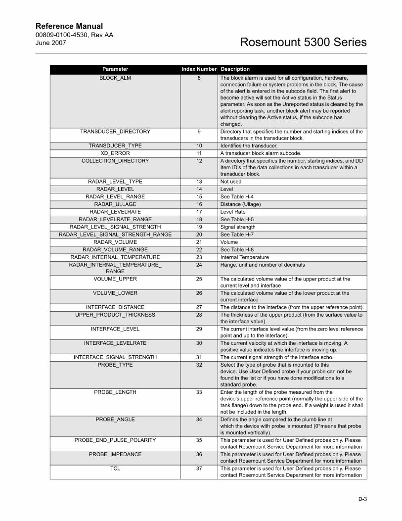
Reference Manual 00809-0100-4530, Rev AAJune 2007 Rosemount 5300 Series
BLOCK_ALM 8 The block alarm is used for all configuration, hardware, connection failure or system problems in the block. The cause of the alert is entered in the subcode field. The first alert to become active will set the Active status in the Status parameter. As soon as the Unreported status is cleared by the alert reporting task, another block alert may be reported without clearing the Active status, if the subcode has changed.
TRANSDUCER_DIRECTORY 9 Directory that specifies the number and starting indices of the transducers in the transducer block.
TRANSDUCER_TYPE 10 Identifies the transducer.XD_ERROR 11 A transducer block alarm subcode.
COLLECTION_DIRECTORY 12 A directory that specifies the number, starting indices, and DD Item ID�s of the data collections in each transducer within a transducer block.
RADAR_LEVEL_TYPE 13 Not usedRADAR_LEVEL 14 Level
RADAR_LEVEL_RANGE 15 See Table H-4RADAR_ULLAGE 16 Distance (Ullage)
RADAR_LEVELRATE 17 Level RateRADAR_LEVELRATE_RANGE 18 See Table H-5
RADAR_LEVEL_SIGNAL_STRENGTH 19 Signal strengthRADAR_LEVEL_SIGNAL_STRENGTH_RANGE 20 See Table H-7
RADAR_VOLUME 21 VolumeRADAR_VOLUME_RANGE 22 See Table H-8
RADAR_INTERNAL_TEMPERATURE 23 Internal TemperatureRADAR_INTERNAL_TEMPERATURE_
RANGE24 Range, unit and number of decimals
VOLUME_UPPER 25 The calculated volume value of the upper product at the current level and interface
VOLUME_LOWER 26 The calculated volume value of the lower product at the current interface
INTERFACE_DISTANCE 27 The distance to the interface (from the upper reference point).UPPER_PRODUCT_THICKNESS 28 The thickness of the upper product (from the surface value to
the interface value).INTERFACE_LEVEL 29 The current interface level value (from the zero level reference
point and up to the interface).INTERFACE_LEVELRATE 30 The current velocity at which the interface is moving. A
positive value indicates the interface is moving up.INTERFACE_SIGNAL_STRENGTH 31 The current signal strength of the interface echo.
PROBE_TYPE 32 Select the type of probe that is mounted to this device. Use User Defined probe if your probe can not be found in the list or if you have done modifications to a standard probe.
PROBE_LENGTH 33 Enter the length of the probe measured from the device's upper reference point (normally the upper side of the tank flange) down to the probe end. If a weight is used it shall not be included in the length.
PROBE_ANGLE 34 Defines the angle compared to the plumb line at which the device with probe is mounted (0°means that probe is mounted vertically).
PROBE_END_PULSE_POLARITY 35 This parameter is used for User Defined probes only. Please contact Rosemount Service Department for more information
PROBE_IMPEDANCE 36 This parameter is used for User Defined probes only. Please contact Rosemount Service Department for more information
TCL 37 This parameter is used for User Defined probes only. Please contact Rosemount Service Department for more information
Parameter Index Number Description
D-3
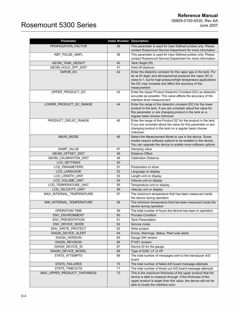
Reference Manual00809-0100-4530, Rev AA
June 2007Rosemount 5300 Series
PROPAGATION_FACTOR 38 This parameter is used for User Defined probes only. Please contact Rosemount Service Department for more information
REF_PULSE_AMPL 39 This parameter is used for User Defined probes only. Please contact Rosemount Service Department for more information
GEOM_TANK_HEIGHT 40 Tank Height (R)GEOM_HOLD_OFF_DIST 41 Hold off distance
VAPOR_DC 42 Enter the dielectric constant for the vapor gas in the tank. For air at 20 degC and atmospherical pressure the vapor DC is close to 1, but for high pressure/high temperature applications the DC may increase and affect the accuracy of the measurement
UPPER_PRODUCT_DC 43 Enter the Upper Product Dielectric Constant (DC) as dielectric accurate as possible. This value affects the accuracy of the interface level measurement
LOWER_PRODUCT_DC_RANGE 44 Enter the range of the dielectric constant (DC) for the lower product in the tank. If you are uncertain about the value for this parameter or are changing product in the tank on a regular basis choose Unknown
PRODUCT_DIELEC_RANGE 45 Enter the range of the Product DC for the product in the tank. If you are uncertain about the value for this parameter or are changing product in the tank on a regular basis choose Unknown
MEAS_MODE 46 Select the Measurement Mode to use in the device. Some modes require software options to be enabled in the device. You can upgrade the device to enable more software options
DAMP_VALUE 47 Damping valueGEOM_OFFSET_DIST 48 Distance Offset
GEOM_CALIBRATION_DIST 49 Calibration DistanceLCD_SETTINGS 50
LCD_PARAMETERS 51 Parameters to showLCD_LANGUAGE 52 Language on display
LCD_LENGTH_UNIT 53 Length unit on displayLCD_VOLUME_UNIT 54 Volume unit on display
LCD_TEMPERATURE_UNIT 55 Temperature unit on displayLCD_VELOCITY_UNIT 56 Velocity unit on display
MAX_INTERNAL_TEMPERATURE 57 The maximum temperature that has been measured inside the device during operation
MIN_INTERNAL_TEMPERATURE 58 The minimum temperature that has been measured inside the device during operation
OPERATION TIME 59 The total number of hours the device has been in operationENV_ENVIRONMENT 60 Process ConditionENV_PRESENTATION 61 Tank PresentationENV_DEVICE_MODE 62 Service mode
ENV_WRITE_PROTECT 63 Write protectDIAGN_DEVICE_ALERT 64 Errors, Warnings, Status, Plant web alerts
DIAGN_VERSION 65 Gauge SW versionDIAGN_REVISION 66 P1451 revisionDIAGN_DEVICE_ID 67 Device ID for the gauge.
DIAGN_DEVICE_MODEL 68 Type of 5300. LF or HFSTATS_ATTEMPTS 69 The total number of messages sent to the transducer A/D
boardSTATS_FAILURES 70 The total number of failed A/D board message attemptsSTATS_TIMEOUTS 71 The total number of timed out A/D board message attempts
MAX_UPPER_PRODUCT_THICKNESS 72 This is the maximum thickness of the upper product that the device is able to measure through. If the thickness of the upper product is larger than this value, the device will not be able to locate the interface echo
Parameter Index Number Description
D-4
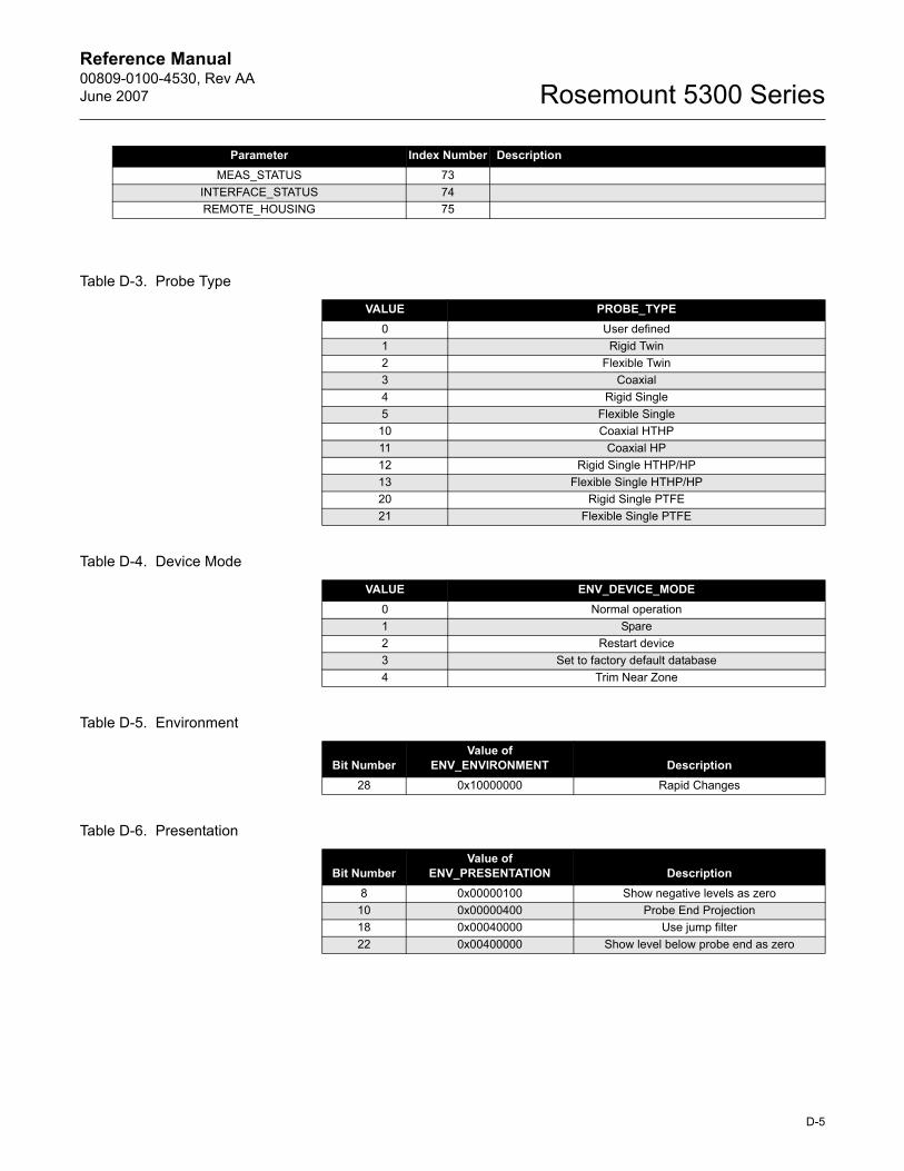
Reference Manual 00809-0100-4530, Rev AAJune 2007 Rosemount 5300 Series
Table D-3. Probe Type
Table D-4. Device Mode
Table D-5. Environment
Table D-6. Presentation
MEAS_STATUS 73INTERFACE_STATUS 74REMOTE_HOUSING 75
Parameter Index Number Description
VALUE PROBE_TYPE0 User defined1 Rigid Twin2 Flexible Twin3 Coaxial4 Rigid Single5 Flexible Single
10 Coaxial HTHP11 Coaxial HP12 Rigid Single HTHP/HP13 Flexible Single HTHP/HP20 Rigid Single PTFE21 Flexible Single PTFE
VALUE ENV_DEVICE_MODE0 Normal operation1 Spare2 Restart device3 Set to factory default database4 Trim Near Zone
Bit NumberValue of
ENV_ENVIRONMENT Description28 0x10000000 Rapid Changes
Bit NumberValue of
ENV_PRESENTATION Description8 0x00000100 Show negative levels as zero
10 0x00000400 Probe End Projection18 0x00040000 Use jump filter22 0x00400000 Show level below probe end as zero
D-5
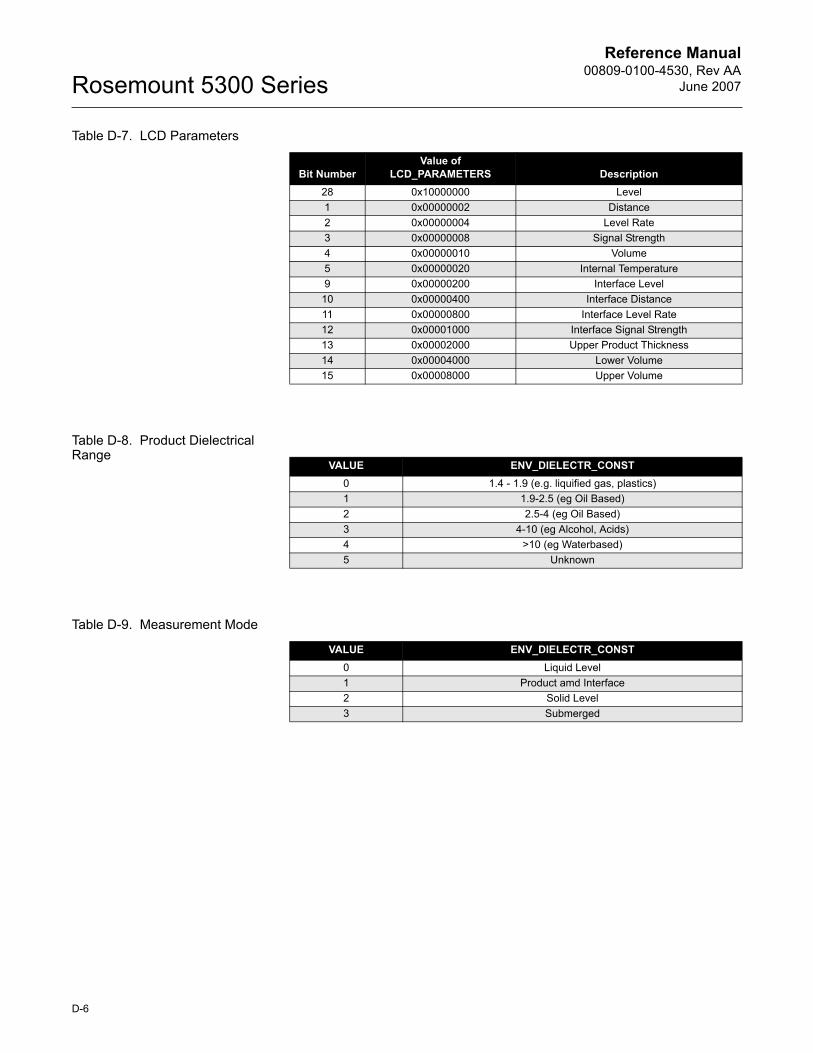
Reference Manual00809-0100-4530, Rev AA
June 2007Rosemount 5300 Series
Table D-7. LCD Parameters
Table D-8. Product Dielectrical Range
Table D-9. Measurement Mode
Bit NumberValue of
LCD_PARAMETERS Description28 0x10000000 Level1 0x00000002 Distance2 0x00000004 Level Rate3 0x00000008 Signal Strength4 0x00000010 Volume5 0x00000020 Internal Temperature9 0x00000200 Interface Level
10 0x00000400 Interface Distance11 0x00000800 Interface Level Rate12 0x00001000 Interface Signal Strength13 0x00002000 Upper Product Thickness14 0x00004000 Lower Volume15 0x00008000 Upper Volume
VALUE ENV_DIELECTR_CONST0 1.4 - 1.9 (e.g. liquified gas, plastics)1 1.9-2.5 (eg Oil Based)2 2.5-4 (eg Oil Based)3 4-10 (eg Alcohol, Acids)4 >10 (eg Waterbased)5 Unknown
VALUE ENV_DIELECTR_CONST0 Liquid Level1 Product amd Interface2 Solid Level3 Submerged
D-6
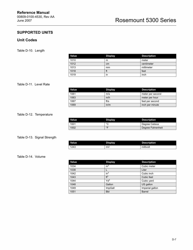
Reference Manual 00809-0100-4530, Rev AAJune 2007 Rosemount 5300 Series
SUPPORTED UNITS
Unit Codes
Table D-10. Length
Table D-11. Level Rate
Table D-12. Temperature
Table D-13. Signal Strength
Table D-14. Volume
Value Display Description1010 m meter1012 cm centimeter1013 mm millimeter1018 ft feet1019 in inch
Value Display Description1061 m/s meter per second1063 m/h meter per hour1067 ft/s feet per second1069 in/m inch per minute
Value Display Description1001 °C Degree Celsius1002 °F Degree Fahrenheit
Value Display Description1243 mV millivolt
Value Display Description1034 m3 Cubic meter1038 L Liter1042 in3 Cubic inch1043 ft3 Cubic feet1044 Yd3 Cubic yard1048 Gallon US gallon1049 ImpGall Imperial gallon1051 Bbl Barrel
D-7
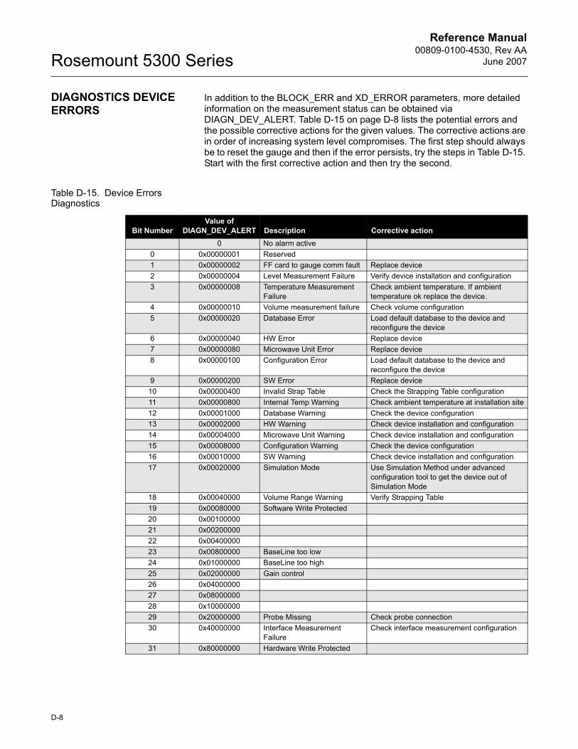
Reference Manual00809-0100-4530, Rev AA
June 2007Rosemount 5300 Series
DIAGNOSTICS DEVICE ERRORS
In addition to the BLOCK_ERR and XD_ERROR parameters, more detailed information on the measurement status can be obtained via DIAGN_DEV_ALERT. Table D-15 on page D-8 lists the potential errors and the possible corrective actions for the given values. The corrective actions are in order of increasing system level compromises. The first step should always be to reset the gauge and then if the error persists, try the steps in Table D-15. Start with the first corrective action and then try the second.
Table D-15. Device Errors Diagnostics
Bit NumberValue of
DIAGN_DEV_ALERT Description Corrective action0 No alarm active
0 0x00000001 Reserved1 0x00000002 FF card to gauge comm fault Replace device2 0x00000004 Level Measurement Failure Verify device installation and configuration3 0x00000008 Temperature Measurement
FailureCheck ambient temperature. If ambient temperature ok replace the device.
4 0x00000010 Volume measurement failure Check volume configuration5 0x00000020 Database Error Load default database to the device and
reconfigure the device6 0x00000040 HW Error Replace device7 0x00000080 Microwave Unit Error Replace device8 0x00000100 Configuration Error Load default database to the device and
reconfigure the device9 0x00000200 SW Error Replace device
10 0x00000400 Invalid Strap Table Check the Strapping Table configuration11 0x00000800 Internal Temp Warning Check ambient temperature at installation site12 0x00001000 Database Warning Check the device configuration13 0x00002000 HW Warning Check device installation and configuration14 0x00004000 Microwave Unit Warning Check device installation and configuration15 0x00008000 Configuration Warning Check the device configuration16 0x00010000 SW Warning Check device installation and configuration17 0x00020000 Simulation Mode Use Simulation Method under advanced
configuration tool to get the device out of Simulation Mode
18 0x00040000 Volume Range Warning Verify Strapping Table19 0x00080000 Software Write Protected20 0x0010000021 0x0020000022 0x0040000023 0x00800000 BaseLine too low24 0x01000000 BaseLine too high25 0x02000000 Gain control26 0x0400000027 0x0800000028 0x1000000029 0x20000000 Probe Missing Check probe connection30 0x40000000 Interface Measurement
FailureCheck interface measurement configuration
31 0x80000000 Hardware Write Protected
D-8
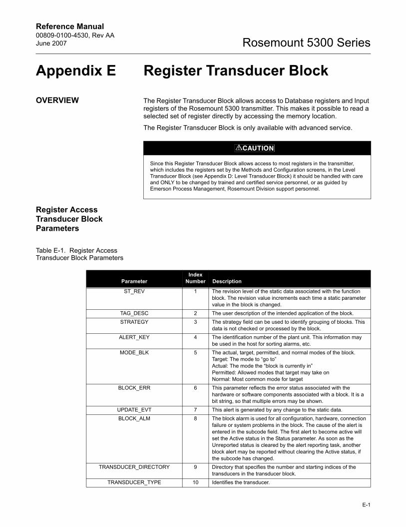
Reference Manual 00809-0100-4530, Rev AAJune 2007 Rosemount 5300 Series
Appendix E Register Transducer Block
OVERVIEW The Register Transducer Block allows access to Database registers and Input registers of the Rosemount 5300 transmitter. This makes it possible to read a selected set of register directly by accessing the memory location.
The Register Transducer Block is only available with advanced service.
Register Access Transducer Block Parameters
Table E-1. Register Access Transducer Block Parameters
Since this Register Transducer Block allows access to most registers in the transmitter, which includes the registers set by the Methods and Configuration screens, in the Level Transducer Block (see Appendix D: Level Transducer Block) it should be handled with care and ONLY to be changed by trained and certified service personnel, or as guided by Emerson Process Management, Rosemount Division support personnel.
ParameterIndex
Number Description
ST_REV 1 The revision level of the static data associated with the function block. The revision value increments each time a static parameter value in the block is changed.
TAG_DESC 2 The user description of the intended application of the block.STRATEGY 3 The strategy field can be used to identify grouping of blocks. This
data is not checked or processed by the block.ALERT_KEY 4 The identification number of the plant unit. This information may
be used in the host for sorting alarms, etc.MODE_BLK 5 The actual, target, permitted, and normal modes of the block.
Target: The mode to �go to�Actual: The mode the �block is currently in�Permitted: Allowed modes that target may take onNormal: Most common mode for target
BLOCK_ERR 6 This parameter reflects the error status associated with the hardware or software components associated with a block. It is a bit string, so that multiple errors may be shown.
UPDATE_EVT 7 This alert is generated by any change to the static data.BLOCK_ALM 8 The block alarm is used for all configuration, hardware, connection
failure or system problems in the block. The cause of the alert is entered in the subcode field. The first alert to become active will set the Active status in the Status parameter. As soon as the Unreported status is cleared by the alert reporting task, another block alert may be reported without clearing the Active status, if the subcode has changed.
TRANSDUCER_DIRECTORY 9 Directory that specifies the number and starting indices of the transducers in the transducer block.
TRANSDUCER_TYPE 10 Identifies the transducer.
E-1
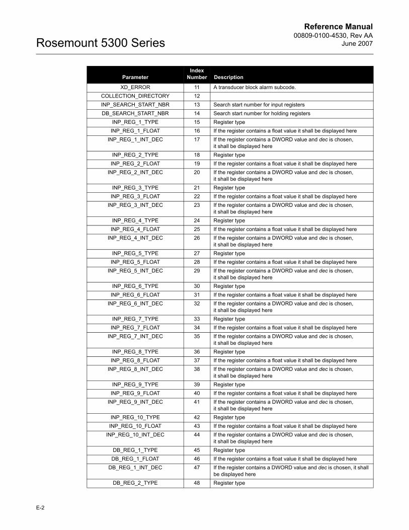
Reference Manual00809-0100-4530, Rev AA
June 2007Rosemount 5300 Series
XD_ERROR 11 A transducer block alarm subcode.COLLECTION_DIRECTORY 12INP_SEARCH_START_NBR 13 Search start number for input registersDB_SEARCH_START_NBR 14 Search start number for holding registers
INP_REG_1_TYPE 15 Register typeINP_REG_1_FLOAT 16 If the register contains a float value it shall be displayed here
INP_REG_1_INT_DEC 17 If the register contains a DWORD value and dec is chosen,it shall be displayed here
INP_REG_2_TYPE 18 Register typeINP_REG_2_FLOAT 19 If the register contains a float value it shall be displayed here
INP_REG_2_INT_DEC 20 If the register contains a DWORD value and dec is chosen,it shall be displayed here
INP_REG_3_TYPE 21 Register typeINP_REG_3_FLOAT 22 If the register contains a float value it shall be displayed here
INP_REG_3_INT_DEC 23 If the register contains a DWORD value and dec is chosen,it shall be displayed here
INP_REG_4_TYPE 24 Register typeINP_REG_4_FLOAT 25 If the register contains a float value it shall be displayed here
INP_REG_4_INT_DEC 26 If the register contains a DWORD value and dec is chosen,it shall be displayed here
INP_REG_5_TYPE 27 Register typeINP_REG_5_FLOAT 28 If the register contains a float value it shall be displayed here
INP_REG_5_INT_DEC 29 If the register contains a DWORD value and dec is chosen,it shall be displayed here
INP_REG_6_TYPE 30 Register typeINP_REG_6_FLOAT 31 If the register contains a float value it shall be displayed here
INP_REG_6_INT_DEC 32 If the register contains a DWORD value and dec is chosen,it shall be displayed here
INP_REG_7_TYPE 33 Register typeINP_REG_7_FLOAT 34 If the register contains a float value it shall be displayed here
INP_REG_7_INT_DEC 35 If the register contains a DWORD value and dec is chosen,it shall be displayed here
INP_REG_8_TYPE 36 Register typeINP_REG_8_FLOAT 37 If the register contains a float value it shall be displayed here
INP_REG_8_INT_DEC 38 If the register contains a DWORD value and dec is chosen,it shall be displayed here
INP_REG_9_TYPE 39 Register typeINP_REG_9_FLOAT 40 If the register contains a float value it shall be displayed here
INP_REG_9_INT_DEC 41 If the register contains a DWORD value and dec is chosen,it shall be displayed here
INP_REG_10_TYPE 42 Register typeINP_REG_10_FLOAT 43 If the register contains a float value it shall be displayed here
INP_REG_10_INT_DEC 44 If the register contains a DWORD value and dec is chosen,it shall be displayed here
DB_REG_1_TYPE 45 Register typeDB_REG_1_FLOAT 46 If the register contains a float value it shall be displayed here
DB_REG_1_INT_DEC 47 If the register contains a DWORD value and dec is chosen, it shall be displayed here
DB_REG_2_TYPE 48 Register type
ParameterIndex
Number Description
E-2
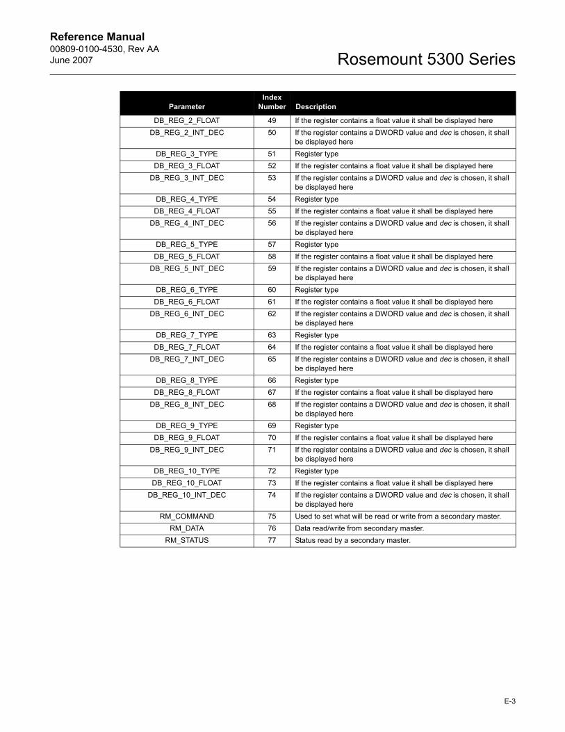
Reference Manual 00809-0100-4530, Rev AAJune 2007 Rosemount 5300 Series
DB_REG_2_FLOAT 49 If the register contains a float value it shall be displayed hereDB_REG_2_INT_DEC 50 If the register contains a DWORD value and dec is chosen, it shall
be displayed hereDB_REG_3_TYPE 51 Register typeDB_REG_3_FLOAT 52 If the register contains a float value it shall be displayed here
DB_REG_3_INT_DEC 53 If the register contains a DWORD value and dec is chosen, it shall be displayed here
DB_REG_4_TYPE 54 Register typeDB_REG_4_FLOAT 55 If the register contains a float value it shall be displayed here
DB_REG_4_INT_DEC 56 If the register contains a DWORD value and dec is chosen, it shall be displayed here
DB_REG_5_TYPE 57 Register typeDB_REG_5_FLOAT 58 If the register contains a float value it shall be displayed here
DB_REG_5_INT_DEC 59 If the register contains a DWORD value and dec is chosen, it shall be displayed here
DB_REG_6_TYPE 60 Register typeDB_REG_6_FLOAT 61 If the register contains a float value it shall be displayed here
DB_REG_6_INT_DEC 62 If the register contains a DWORD value and dec is chosen, it shall be displayed here
DB_REG_7_TYPE 63 Register typeDB_REG_7_FLOAT 64 If the register contains a float value it shall be displayed here
DB_REG_7_INT_DEC 65 If the register contains a DWORD value and dec is chosen, it shall be displayed here
DB_REG_8_TYPE 66 Register typeDB_REG_8_FLOAT 67 If the register contains a float value it shall be displayed here
DB_REG_8_INT_DEC 68 If the register contains a DWORD value and dec is chosen, it shall be displayed here
DB_REG_9_TYPE 69 Register typeDB_REG_9_FLOAT 70 If the register contains a float value it shall be displayed here
DB_REG_9_INT_DEC 71 If the register contains a DWORD value and dec is chosen, it shall be displayed here
DB_REG_10_TYPE 72 Register typeDB_REG_10_FLOAT 73 If the register contains a float value it shall be displayed here
DB_REG_10_INT_DEC 74 If the register contains a DWORD value and dec is chosen, it shall be displayed here
RM_COMMAND 75 Used to set what will be read or write from a secondary master.RM_DATA 76 Data read/write from secondary master.
RM_STATUS 77 Status read by a secondary master.
ParameterIndex
Number Description
E-3

Reference Manual00809-0100-4530, Rev AA
June 2007Rosemount 5300 Series
E-4
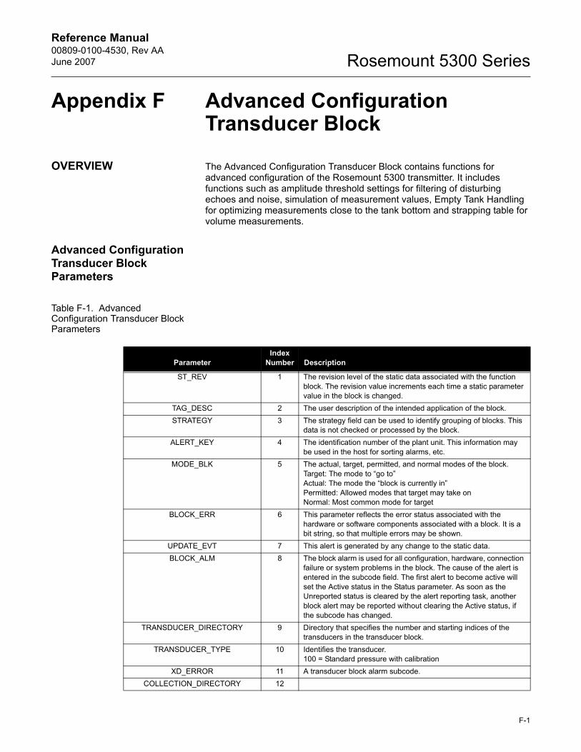
Reference Manual 00809-0100-4530, Rev AAJune 2007 Rosemount 5300 Series
Appendix F Advanced Configuration Transducer Block
OVERVIEW The Advanced Configuration Transducer Block contains functions for advanced configuration of the Rosemount 5300 transmitter. It includes functions such as amplitude threshold settings for filtering of disturbing echoes and noise, simulation of measurement values, Empty Tank Handling for optimizing measurements close to the tank bottom and strapping table for volume measurements.
Advanced Configuration Transducer Block Parameters
Table F-1. Advanced Configuration Transducer Block Parameters
ParameterIndex
Number Description
ST_REV 1 The revision level of the static data associated with the function block. The revision value increments each time a static parameter value in the block is changed.
TAG_DESC 2 The user description of the intended application of the block.STRATEGY 3 The strategy field can be used to identify grouping of blocks. This
data is not checked or processed by the block.ALERT_KEY 4 The identification number of the plant unit. This information may
be used in the host for sorting alarms, etc.MODE_BLK 5 The actual, target, permitted, and normal modes of the block.
Target: The mode to �go to�Actual: The mode the �block is currently in�Permitted: Allowed modes that target may take onNormal: Most common mode for target
BLOCK_ERR 6 This parameter reflects the error status associated with the hardware or software components associated with a block. It is a bit string, so that multiple errors may be shown.
UPDATE_EVT 7 This alert is generated by any change to the static data.BLOCK_ALM 8 The block alarm is used for all configuration, hardware, connection
failure or system problems in the block. The cause of the alert is entered in the subcode field. The first alert to become active will set the Active status in the Status parameter. As soon as the Unreported status is cleared by the alert reporting task, another block alert may be reported without clearing the Active status, if the subcode has changed.
TRANSDUCER_DIRECTORY 9 Directory that specifies the number and starting indices of the transducers in the transducer block.
TRANSDUCER_TYPE 10 Identifies the transducer.100 = Standard pressure with calibration
XD_ERROR 11 A transducer block alarm subcode.COLLECTION_DIRECTORY 12
F-1

Reference Manual00809-0100-4530, Rev AA
June 2007Rosemount 5300 Series
AMPLITUDE_THRESHOLD_CURVE 13 ATC: filters out weak disturbance echoes and noise.SIMULATION_MODE 14 Simulation of measurement values.
SET_CONSTANT_THRESHOLD 15 A constant amplitude threshold can be used to filter out noise.RADAR_LEVEL_RANGE 16
RADAR_LEVEL_SIGNAL_STRENGTH_RANGE
17
RADAR_VOLUME_RANGE 18ENV_PRESENTATION 19
PROBE_END_THRESH 20REFERENCE_THRESH 21INTERFACE_THRESH 22
FULL_TANK_THRESH_OFFSET 23PEP_PRODUCT_DC 24
AUTO_CONF_MEAS_FUNC 25ECHO_TIME_OUT 26
CLOSE_DIST 27USED_PROBE_END_THRESH 28USED_REFERENCE_THRESH 29USED_INTERFACE_THRESH 30USED_TANK_PRESENTATION 31
USED_ECHO_TIME_OUT 32USED_CLOSE_DIST 33
SW_SUPPORT2 34USED_HOLD_OFF_DIST 35
USED_PEP_PRODUCT_DC 36START_CODE 37UNIT_CODE 38
ENV_SET_START_CODE 39PROBE_END_ANCHORING 40PEP_PROBE_END_OFFSET 41
USED_PEP_ PROBE_END_OFFSET 42VOL_VOLUME_CALC_METHOD 43 Tank geometry
VOL_IDEAL_DIAMETER 44 Tank diameterVOL_IDEAL_LENGTH 45 Tank length
VOL_VOLUME_OFFSET 46 Volume offsetVOL_STRAP_TABLE_LENGTH 47 Number of strap points
VOL_STRAP_LEVEL 48 Strap value level 1-20 pointsVOL_STRAP_VOLUME 49 Strap value volume 1-20 points
ECHO_REG 50 Read Echo distance, amplitude and class from gauge.ECHO_WRITE 51 Echo Found/False Record.
ParameterIndex
Number Description
F-2
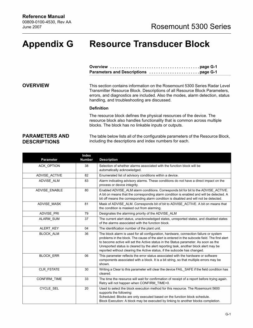
Reference Manual 00809-0100-4530, Rev AAJune 2007 Rosemount 5300 Series
Appendix G Resource Transducer Block
Overview . . . . . . . . . . . . . . . . . . . . . . . . . . . . . . . . . . . . . . . page G-1Parameters and Descriptions . . . . . . . . . . . . . . . . . . . . . . page G-1
OVERVIEW This section contains information on the Rosemount 5300 Series Radar Level Transmitter Resource Block. Descriptions of all Resource Block Parameters, errors, and diagnostics are included. Also the modes, alarm detection, status handling, and troubleshooting are discussed.
Definition
The resource block defines the physical resources of the device. The resource block also handles functionality that is common across multiple blocks. The block has no linkable inputs or outputs.
PARAMETERS AND DESCRIPTIONS
The table below lists all of the configurable parameters of the Resource Block, including the descriptions and index numbers for each.
ParameterIndex
Number Description
ACK_OPTION 38 Selection of whether alarms associated with the function block will be automatically acknowledged.
ADVISE_ACTIVE 82 Enumerated list of advisory conditions within a device. ADVISE_ALM 83 Alarm indicating advisory alarms. These conditions do not have a direct impact on the
process or device integrity.ADVISE_ENABLE 80 Enabled ADVISE_ALM alarm conditions. Corresponds bit for bit to the ADVISE_ACTIVE.
A bit on means that the corresponding alarm condition is enabled and will be detected. A bit off means the corresponding alarm condition is disabled and will not be detected.
ADVISE_MASK 81 Mask of ADVISE_ALM. Corresponds bit of bit to ADVISE_ACTIVE. A bit on means that the condition is masked out from alarming.
ADVISE_PRI 79 Designates the alarming priority of the ADVISE_ALMALARM_SUM 37 The current alert status, unacknowledged states, unreported states, and disabled states
of the alarms associated with the function block. ALERT_KEY 04 The identification number of the plant unit. BLOCK_ALM 36 The block alarm is used for all configuration, hardware, connection failure or system
problems in the block. The cause of the alert is entered in the subcode field. The first alert to become active will set the Active status in the Status parameter. As soon as the Unreported status is cleared by the alert reporting task, another block alert may be reported without clearing the Active status, if the subcode has changed.
BLOCK_ERR 06 This parameter reflects the error status associated with the hardware or software components associated with a block. It is a bit string, so that multiple errors may be shown.
CLR_FSTATE 30 Writing a Clear to this parameter will clear the device FAIL_SAFE if the field condition has cleared.
CONFIRM_TIME 33 The time the resource will wait for confirmation of receipt of a report before trying again. Retry will not happen when CONFIRM_TIME=0.
CYCLE_SEL 20 Used to select the block execution method for this resource. The Rosemount 5600 supports the following:Scheduled: Blocks are only executed based on the function block schedule.Block Execution: A block may be executed by linking to another blocks completion.
G-1
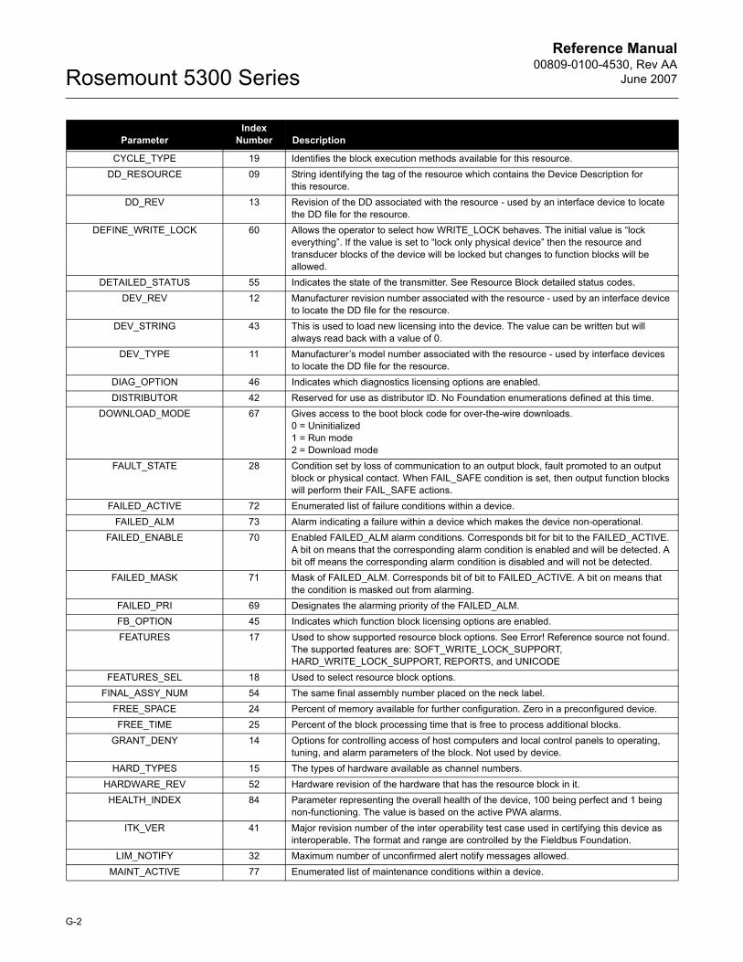
Reference Manual00809-0100-4530, Rev AA
June 2007Rosemount 5300 Series
CYCLE_TYPE 19 Identifies the block execution methods available for this resource.DD_RESOURCE 09 String identifying the tag of the resource which contains the Device Description for
this resource.DD_REV 13 Revision of the DD associated with the resource - used by an interface device to locate
the DD file for the resource.DEFINE_WRITE_LOCK 60 Allows the operator to select how WRITE_LOCK behaves. The initial value is �lock
everything�. If the value is set to �lock only physical device� then the resource and transducer blocks of the device will be locked but changes to function blocks will be allowed.
DETAILED_STATUS 55 Indicates the state of the transmitter. See Resource Block detailed status codes.DEV_REV 12 Manufacturer revision number associated with the resource - used by an interface device
to locate the DD file for the resource.DEV_STRING 43 This is used to load new licensing into the device. The value can be written but will
always read back with a value of 0.DEV_TYPE 11 Manufacturer�s model number associated with the resource - used by interface devices
to locate the DD file for the resource.DIAG_OPTION 46 Indicates which diagnostics licensing options are enabled. DISTRIBUTOR 42 Reserved for use as distributor ID. No Foundation enumerations defined at this time.
DOWNLOAD_MODE 67 Gives access to the boot block code for over-the-wire downloads.0 = Uninitialized 1 = Run mode2 = Download mode
FAULT_STATE 28 Condition set by loss of communication to an output block, fault promoted to an output block or physical contact. When FAIL_SAFE condition is set, then output function blocks will perform their FAIL_SAFE actions.
FAILED_ACTIVE 72 Enumerated list of failure conditions within a device. FAILED_ALM 73 Alarm indicating a failure within a device which makes the device non-operational.
FAILED_ENABLE 70 Enabled FAILED_ALM alarm conditions. Corresponds bit for bit to the FAILED_ACTIVE. A bit on means that the corresponding alarm condition is enabled and will be detected. A bit off means the corresponding alarm condition is disabled and will not be detected.
FAILED_MASK 71 Mask of FAILED_ALM. Corresponds bit of bit to FAILED_ACTIVE. A bit on means that the condition is masked out from alarming.
FAILED_PRI 69 Designates the alarming priority of the FAILED_ALM.FB_OPTION 45 Indicates which function block licensing options are enabled. FEATURES 17 Used to show supported resource block options. See Error! Reference source not found.
The supported features are: SOFT_WRITE_LOCK_SUPPORT, HARD_WRITE_LOCK_SUPPORT, REPORTS, and UNICODE
FEATURES_SEL 18 Used to select resource block options.FINAL_ASSY_NUM 54 The same final assembly number placed on the neck label.
FREE_SPACE 24 Percent of memory available for further configuration. Zero in a preconfigured device.FREE_TIME 25 Percent of the block processing time that is free to process additional blocks.
GRANT_DENY 14 Options for controlling access of host computers and local control panels to operating, tuning, and alarm parameters of the block. Not used by device.
HARD_TYPES 15 The types of hardware available as channel numbers. HARDWARE_REV 52 Hardware revision of the hardware that has the resource block in it.HEALTH_INDEX 84 Parameter representing the overall health of the device, 100 being perfect and 1 being
non-functioning. The value is based on the active PWA alarms.ITK_VER 41 Major revision number of the inter operability test case used in certifying this device as
interoperable. The format and range are controlled by the Fieldbus Foundation.LIM_NOTIFY 32 Maximum number of unconfirmed alert notify messages allowed.
MAINT_ACTIVE 77 Enumerated list of maintenance conditions within a device.
ParameterIndex
Number Description
G-2
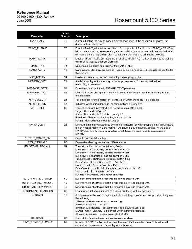
Reference Manual 00809-0100-4530, Rev AAJune 2007 Rosemount 5300 Series
MAINT_ALM 78 Alarm indicating the device needs maintenance soon. If the condition is ignored, the device will eventually fail.
MAINT_ENABLE 75 Enabled MAINT_ALM alarm conditions. Corresponds bit for bit to the MAINT_ACTIVE. A bit on means that the corresponding alarm condition is enabled and will be detected. A bit off means the corresponding alarm condition is disabled and will not be detected.
MAINT_MASK 76 Mask of MAINT_ALM. Corresponds bit of bit to MAINT_ACTIVE. A bit on means that the condition is masked out from alarming.
MAINT_PRI 74 Designates the alarming priority of the MAINT_ALMMANUFAC_ID 10 Manufacturer identification number � used by an interface device to locate the DD file for
the resource.MAX_NOTIFY 31 Maximum number of unconfirmed notify messages possible.
MEMORY_SIZE 22 Available configuration memory in the empty resource. To be checked before attempting a download.
MESSAGE_DATE 57 Date associated with the MESSAGE_TEXT parameter.MESSAGE_TEXT 58 Used to indicate changes made by the user to the device's installation, configuration,
or calibration.MIN_CYCLE_T 21 Time duration of the shortest cycle interval of which the resource is capable.MISC_OPTION 47 Indicates which miscellaneous licensing options are enabled.
MODE_BLK 05 The actual, target, permitted, and normal modes of the block:Target: The mode to �go to�Actual: The mode the �block is currently in�Permitted: Allowed modes that target may take onNormal: Most common mode for actual
NV_CYCLE_T 23 Minimum time interval specified by the manufacturer for writing copies of NV parameters to non-volatile memory. Zero means it will never be automatically copied. At the end of NV_CYCLE_T, only those parameters which have changed need to be updated in NVRAM.
OUTPUT_BOARD_SN 53 Output board serial number.PWA_SIMULATE 85 Parameter allowing simulation of PWA alarms.
RB_SFTWR_REV_ALL 51 The string will contains the following fields:Major rev: 1-3 characters, decimal number 0-255Minor rev: 1-3 characters, decimal number 0-255Build rev: 1-5 characters, decimal number 0-255Time of build: 8 characters, xx:xx:xx, military timeDay of week of build: 3 characters, Sun, Mon,...Month of build: 3 characters, Jan, Feb.Day of month of build: 1-2 characters, decimal number 1-31Year of build: 4 characters, decimalBuilder: 7 characters, login name of builder
RB_SFTWR_REV_BUILD 50 Build of software that the resource block was created with.RB_SFTWR_REV_MAJOR 48 Major revision of software that the resource block was created with.RB_SFTWR_REV_MINOR 49 Minor revision of software that the resource block was created with.RECOMMENDED_ACTION 68 Enumerated list of recommended actions displayed with a device alert.
RESTART 16 Allows a manual restart to be initiated. Several degrees of restart are possible. They are the following:1 Run � nominal state when not restarting2 Restart resource � not used 3 Restart with defaults � set parameters to default values. See START_WITH_DEFAULTS below for which parameters are set.4 Restart processor � does a warm start of CPU.
RS_STATE 07 State of the function block application state machine.SAVE_CONFIG_BLOCKS 62 Number of EEPROM blocks that have been modified since last burn. This value will
count down to zero when the configuration is saved.
ParameterIndex
Number Description
G-3
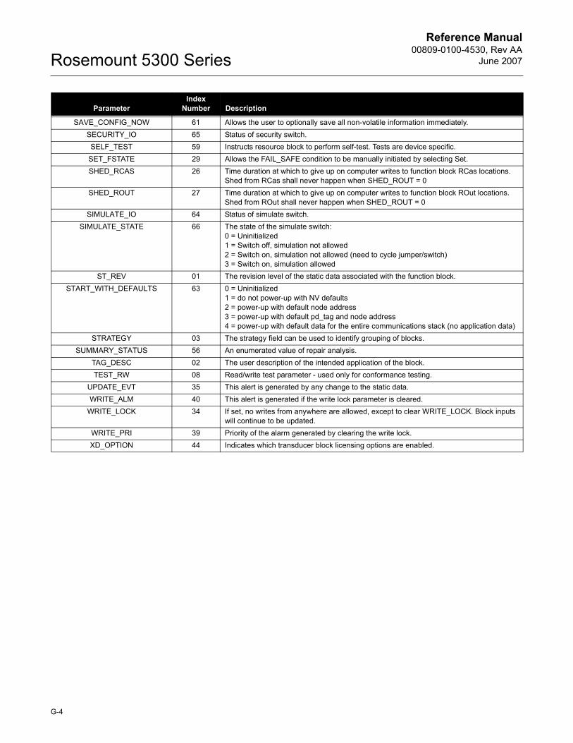
Reference Manual00809-0100-4530, Rev AA
June 2007Rosemount 5300 Series
SAVE_CONFIG_NOW 61 Allows the user to optionally save all non-volatile information immediately.SECURITY_IO 65 Status of security switch.SELF_TEST 59 Instructs resource block to perform self-test. Tests are device specific.
SET_FSTATE 29 Allows the FAIL_SAFE condition to be manually initiated by selecting Set.SHED_RCAS 26 Time duration at which to give up on computer writes to function block RCas locations.
Shed from RCas shall never happen when SHED_ROUT = 0SHED_ROUT 27 Time duration at which to give up on computer writes to function block ROut locations.
Shed from ROut shall never happen when SHED_ROUT = 0SIMULATE_IO 64 Status of simulate switch.
SIMULATE_STATE 66 The state of the simulate switch:0 = Uninitialized1 = Switch off, simulation not allowed2 = Switch on, simulation not allowed (need to cycle jumper/switch)3 = Switch on, simulation allowed
ST_REV 01 The revision level of the static data associated with the function block. START_WITH_DEFAULTS 63 0 = Uninitialized
1 = do not power-up with NV defaults2 = power-up with default node address3 = power-up with default pd_tag and node address4 = power-up with default data for the entire communications stack (no application data)
STRATEGY 03 The strategy field can be used to identify grouping of blocks. SUMMARY_STATUS 56 An enumerated value of repair analysis.
TAG_DESC 02 The user description of the intended application of the block.TEST_RW 08 Read/write test parameter - used only for conformance testing.
UPDATE_EVT 35 This alert is generated by any change to the static data.WRITE_ALM 40 This alert is generated if the write lock parameter is cleared.
WRITE_LOCK 34 If set, no writes from anywhere are allowed, except to clear WRITE_LOCK. Block inputs will continue to be updated.
WRITE_PRI 39 Priority of the alarm generated by clearing the write lock.XD_OPTION 44 Indicates which transducer block licensing options are enabled.
ParameterIndex
Number Description
G-4
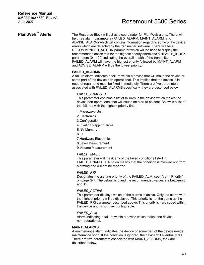
Reference Manual 00809-0100-4530, Rev AAJune 2007 Rosemount 5300 Series
PlantWeb� Alerts The Resource Block will act as a coordinator for PlantWeb alerts. There will be three alarm parameters (FAILED_ALARM, MAINT_ALARM, and ADVISE_ALARM) which will contain information regarding some of the device errors which are detected by the transmitter software. There will be a RECOMMENDED_ACTION parameter which will be used to display the recommended action text for the highest priority alarm and a HEALTH_INDEX parameters (0 - 100) indicating the overall health of the transmitter. FAILED_ALARM will have the highest priority followed by MAINT_ALARM and ADVISE_ALARM will be the lowest priority.
FAILED_ALARMSA failure alarm indicates a failure within a device that will make the device or some part of the device non-operational. This implies that the device is in need of repair and must be fixed immediately. There are five parameters associated with FAILED_ALARMS specifically, they are described below.
FAILED_ENABLEDThis parameter contains a list of failures in the device which makes the device non-operational that will cause an alert to be sent. Below is a list of the failures with the highest priority first.
1.Microwave Unit2.Electronics3.Configuration4.Invalid Strapping Table5.NV Memory6.IO7.Hardware Electronics8.Level Measurement9.Volume Measurement
FAILED_MASKThis parameter will mask any of the failed conditions listed in FAILED_ENABLED. A bit on means that the condition is masked out from alarming and will not be reported.
FAILED_PRIDesignates the alerting priority of the FAILED_ALM, see �Alarm Priority� on page G-7. The default is 0 and the recommended values are between 8 and 15.
FAILED_ACTIVEThis parameter displays which of the alarms is active. Only the alarm with the highest priority will be displayed. This priority is not the same as the FAILED_PRI parameter described above. This priority is hard coded within the device and is not user configurable.
FAILED_ALMAlarm indicating a failure within a device which makes the device non-operational.
MAINT_ALARMSA maintenance alarm indicates the device or some part of the device needs maintenance soon. If the condition is ignored, the device will eventually fail. There are five parameters associated with MAINT_ALARMS, they are described below.
G-5
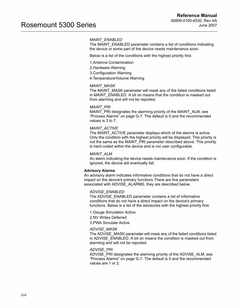
Reference Manual00809-0100-4530, Rev AA
June 2007Rosemount 5300 Series
MAINT_ENABLEDThe MAINT_ENABLED parameter contains a list of conditions indicating the device or some part of the device needs maintenance soon.
Below is a list of the conditions with the highest priority first.
1.Antenna Contamination2.Hardware Warning3.Configuration Warning4.Temperature/Volume Warning
MAINT_MASKThe MAINT_MASK parameter will mask any of the failed conditions listed in MAINT_ENABLED. A bit on means that the condition is masked out from alarming and will not be reported.
MAINT_PRIMAINT_PRI designates the alarming priority of the MAINT_ALM, see �Process Alarms� on page G-7. The default is 0 and the recommended values is 3 to 7.
MAINT_ACTIVEThe MAINT_ACTIVE parameter displays which of the alarms is active. Only the condition with the highest priority will be displayed. This priority is not the same as the MAINT_PRI parameter described above. This priority is hard coded within the device and is not user configurable.
MAINT_ALMAn alarm indicating the device needs maintenance soon. If the condition is ignored, the device will eventually fail.
Advisory AlarmsAn advisory alarm indicates informative conditions that do not have a direct impact on the device's primary functions There are five parameters associated with ADVISE_ALARMS, they are described below.
ADVISE_ENABLEDThe ADVISE_ENABLED parameter contains a list of informative conditions that do not have a direct impact on the device's primary functions. Below is a list of the advisories with the highest priority first.
1.Gauge Simulation Active2.NV Writes Deferred3.PWA Simulate ActiveADVISE_MASKThe ADVISE_MASK parameter will mask any of the failed conditions listed in ADVISE_ENABLED. A bit on means the condition is masked out from alarming and will not be reported.
ADVISE_PRIADVISE_PRI designates the alarming priority of the ADVISE_ALM, see �Process Alarms� on page G-7. The default is 0 and the recommended values are 1 or 2.
G-6
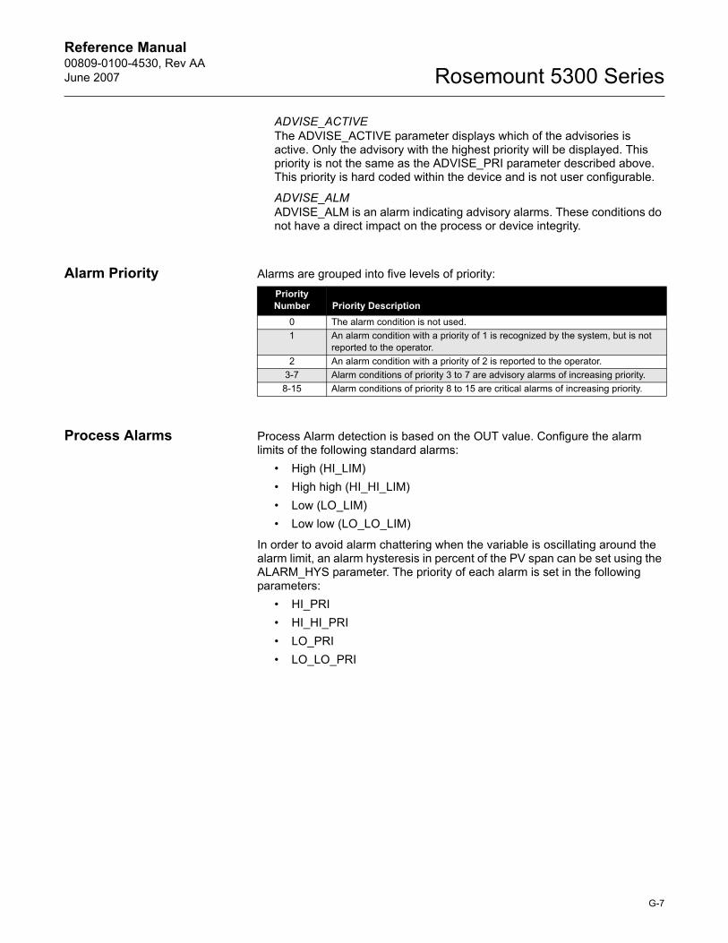
Reference Manual 00809-0100-4530, Rev AAJune 2007 Rosemount 5300 Series
ADVISE_ACTIVEThe ADVISE_ACTIVE parameter displays which of the advisories is active. Only the advisory with the highest priority will be displayed. This priority is not the same as the ADVISE_PRI parameter described above. This priority is hard coded within the device and is not user configurable.
ADVISE_ALMADVISE_ALM is an alarm indicating advisory alarms. These conditions do not have a direct impact on the process or device integrity.
Alarm Priority Alarms are grouped into five levels of priority:
Process Alarms Process Alarm detection is based on the OUT value. Configure the alarm limits of the following standard alarms:
� High (HI_LIM)� High high (HI_HI_LIM)� Low (LO_LIM)� Low low (LO_LO_LIM)
In order to avoid alarm chattering when the variable is oscillating around the alarm limit, an alarm hysteresis in percent of the PV span can be set using the ALARM_HYS parameter. The priority of each alarm is set in the following parameters:
� HI_PRI� HI_HI_PRI� LO_PRI� LO_LO_PRI
Priority Number Priority Description
0 The alarm condition is not used.1 An alarm condition with a priority of 1 is recognized by the system, but is not
reported to the operator.2 An alarm condition with a priority of 2 is reported to the operator.
3-7 Alarm conditions of priority 3 to 7 are advisory alarms of increasing priority.8-15 Alarm conditions of priority 8 to 15 are critical alarms of increasing priority.
G-7
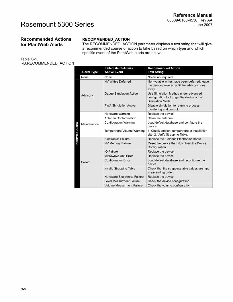
Reference Manual00809-0100-4530, Rev AA
June 2007Rosemount 5300 Series
Recommended Actions for PlantWeb Alerts
RECOMMENDED_ACTION The RECOMMENDED_ACTION parameter displays a text string that will give a recommended course of action to take based on which type and which specific event of the PlantWeb alerts are active.
Table G-1. RB.RECOMMENDED_ACTION
Alarm TypeFailed/Maint/AdviseActive Event
Recommended Action Text String
None None No action requiredPl
antW
eb A
lert
s
Advisory
NV Writes Deferred Non-volatile writes have been deferred, leave the device powered until the advisory goes away.
Gauge Simulation Active Use Simulation Method under advanced configuration tool to get the device out of Simulation Mode.
PWA Simulation Active Disable simulation to return to process monitoring and control.
Maintenance
Hardware Warning Replace the device.Antenna Contamination Clean the antenna.Configuration Warning Load default database and configure the
device.Temperature/Volume Warning 1. Check ambient temperature at installation
site 2. Verify Strapping Table.
Failed
Electronics Failure Replace the Fieldbus Electronics Board.NV Memory Failure Reset the device then download the Device
Configuration.IO Failure Replace the device.Microwave Unit Error Replace the device.Configuration Error Load default database and reconfigure the
device.Invalid Strapping Table Check that the strapping table values are input
in ascending order.Hardware Electronics Failure Replace the device.Level Measurment Failure Check the device configuration.Volume Measurment Failure Check the volume configuration.
G-8

Reference Manual 00809-0100-4530, Rev AAJune 2007 Rosemount 5300 Series
Appendix H Analog-Input Block
Simulation . . . . . . . . . . . . . . . . . . . . . . . . . . . . . . . . . . . . . . page H-3Damping . . . . . . . . . . . . . . . . . . . . . . . . . . . . . . . . . . . . . . . page H-4Signal Conversion . . . . . . . . . . . . . . . . . . . . . . . . . . . . . . . page H-5Block Errors . . . . . . . . . . . . . . . . . . . . . . . . . . . . . . . . . . . . page H-6Modes . . . . . . . . . . . . . . . . . . . . . . . . . . . . . . . . . . . . . . . . . page H-6Alarm Detection . . . . . . . . . . . . . . . . . . . . . . . . . . . . . . . . . page H-7Advanced Features . . . . . . . . . . . . . . . . . . . . . . . . . . . . . . . page H-8Configure the AI Block . . . . . . . . . . . . . . . . . . . . . . . . . . . . page H-9
Figure H-1. Analog-Input Block
The Analog Input (AI) function block processes field device measurements and makes them available to other function blocks. The output value from the AI block is in engineering units and contains a status indicating the quality of the measurement. The measuring device may have several measurements or derived values available in different channels. Use the channel number to define the variable that the AI block processes.
The AI block supports alarming, signal scaling, signal filtering, signal status calculation, mode control, and simulation. In Automatic mode, the block�s output parameter (OUT) reflects the process variable (PV) value and status. In Manual mode, OUT may be set manually. The Manual mode is reflected on the output status. A discrete output (OUT_D) is provided to indicate whether a selected alarm condition is active. Alarm detection is based on the OUT value and user specified alarm limits. Figure H-2 on page H-4 illustrates the internal components of the AI function block, and Table H-1 lists the AI block parameters and their units of measure, descriptions, and index numbers.
Table H-1. Definitions of Analog Input Function Block System Parameters
OUT=The block output value and statusOUT_D=Discrete output that signals a selected alarm condition
OUT_D
AI OUT
FIE
LDB
US
-FB
US_
31A
ParameterIndex
Number Units Description
ACK_OPTION 23 None Used to set auto acknowledgment of alarms.ALARM_HYS 24 Percent The amount the alarm value must return within the alarm limit before the associated
active alarm condition clears.
H-1
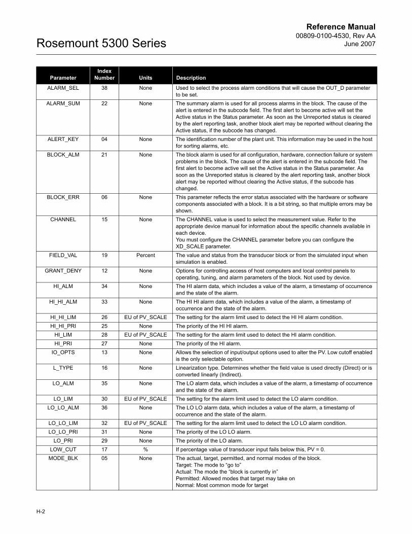
Reference Manual00809-0100-4530, Rev AA
June 2007Rosemount 5300 Series
ALARM_SEL 38 None Used to select the process alarm conditions that will cause the OUT_D parameter to be set.
ALARM_SUM 22 None The summary alarm is used for all process alarms in the block. The cause of the alert is entered in the subcode field. The first alert to become active will set the Active status in the Status parameter. As soon as the Unreported status is cleared by the alert reporting task, another block alert may be reported without clearing the Active status, if the subcode has changed.
ALERT_KEY 04 None The identification number of the plant unit. This information may be used in the host for sorting alarms, etc.
BLOCK_ALM 21 None The block alarm is used for all configuration, hardware, connection failure or system problems in the block. The cause of the alert is entered in the subcode field. The first alert to become active will set the Active status in the Status parameter. As soon as the Unreported status is cleared by the alert reporting task, another block alert may be reported without clearing the Active status, if the subcode has changed.
BLOCK_ERR 06 None This parameter reflects the error status associated with the hardware or software components associated with a block. It is a bit string, so that multiple errors may be shown.
CHANNEL 15 None The CHANNEL value is used to select the measurement value. Refer to the appropriate device manual for information about the specific channels available in each device.You must configure the CHANNEL parameter before you can configure the XD_SCALE parameter.
FIELD_VAL 19 Percent The value and status from the transducer block or from the simulated input when simulation is enabled.
GRANT_DENY 12 None Options for controlling access of host computers and local control panels to operating, tuning, and alarm parameters of the block. Not used by device.
HI_ALM 34 None The HI alarm data, which includes a value of the alarm, a timestamp of occurrence and the state of the alarm.
HI_HI_ALM 33 None The HI HI alarm data, which includes a value of the alarm, a timestamp of occurrence and the state of the alarm.
HI_HI_LIM 26 EU of PV_SCALE The setting for the alarm limit used to detect the HI HI alarm condition.HI_HI_PRI 25 None The priority of the HI HI alarm.
HI_LIM 28 EU of PV_SCALE The setting for the alarm limit used to detect the HI alarm condition.HI_PRI 27 None The priority of the HI alarm.
IO_OPTS 13 None Allows the selection of input/output options used to alter the PV. Low cutoff enabled is the only selectable option.
L_TYPE 16 None Linearization type. Determines whether the field value is used directly (Direct) or is converted linearly (Indirect).
LO_ALM 35 None The LO alarm data, which includes a value of the alarm, a timestamp of occurrence and the state of the alarm.
LO_LIM 30 EU of PV_SCALE The setting for the alarm limit used to detect the LO alarm condition.LO_LO_ALM 36 None The LO LO alarm data, which includes a value of the alarm, a timestamp of
occurrence and the state of the alarm.LO_LO_LIM 32 EU of PV_SCALE The setting for the alarm limit used to detect the LO LO alarm condition.LO_LO_PRI 31 None The priority of the LO LO alarm.
LO_PRI 29 None The priority of the LO alarm.LOW_CUT 17 % If percentage value of transducer input fails below this, PV = 0.
MODE_BLK 05 None The actual, target, permitted, and normal modes of the block. Target: The mode to �go to�Actual: The mode the �block is currently in�Permitted: Allowed modes that target may take onNormal: Most common mode for target
ParameterIndex
Number Units Description
H-2
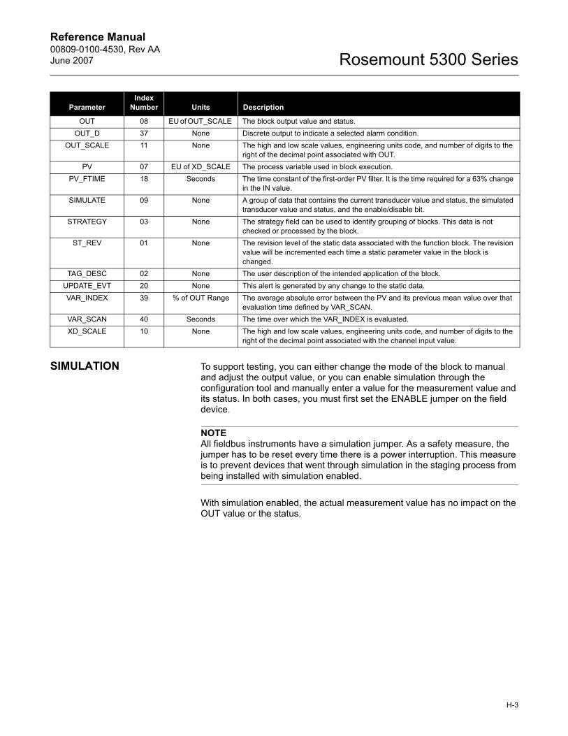
Reference Manual 00809-0100-4530, Rev AAJune 2007 Rosemount 5300 Series
SIMULATION To support testing, you can either change the mode of the block to manual and adjust the output value, or you can enable simulation through the configuration tool and manually enter a value for the measurement value and its status. In both cases, you must first set the ENABLE jumper on the field device.
NOTEAll fieldbus instruments have a simulation jumper. As a safety measure, the jumper has to be reset every time there is a power interruption. This measure is to prevent devices that went through simulation in the staging process from being installed with simulation enabled.
With simulation enabled, the actual measurement value has no impact on the OUT value or the status.
OUT 08 EU of OUT_SCALE The block output value and status.OUT_D 37 None Discrete output to indicate a selected alarm condition.
OUT_SCALE 11 None The high and low scale values, engineering units code, and number of digits to the right of the decimal point associated with OUT.
PV 07 EU of XD_SCALE The process variable used in block execution.PV_FTIME 18 Seconds The time constant of the first-order PV filter. It is the time required for a 63% change
in the IN value.SIMULATE 09 None A group of data that contains the current transducer value and status, the simulated
transducer value and status, and the enable/disable bit.STRATEGY 03 None The strategy field can be used to identify grouping of blocks. This data is not
checked or processed by the block.ST_REV 01 None The revision level of the static data associated with the function block. The revision
value will be incremented each time a static parameter value in the block is changed.
TAG_DESC 02 None The user description of the intended application of the block.UPDATE_EVT 20 None This alert is generated by any change to the static data.VAR_INDEX 39 % of OUT Range The average absolute error between the PV and its previous mean value over that
evaluation time defined by VAR_SCAN.VAR_SCAN 40 Seconds The time over which the VAR_INDEX is evaluated.XD_SCALE 10 None The high and low scale values, engineering units code, and number of digits to the
right of the decimal point associated with the channel input value.
ParameterIndex
Number Units Description
H-3
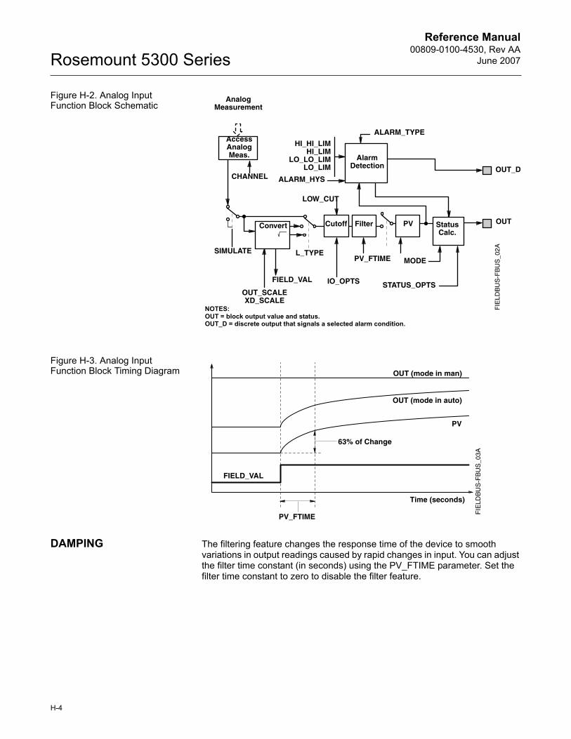
Reference Manual00809-0100-4530, Rev AA
June 2007Rosemount 5300 Series
Figure H-2. Analog Input Function Block Schematic
Figure H-3. Analog Input Function Block Timing Diagram
DAMPING The filtering feature changes the response time of the device to smooth variations in output readings caused by rapid changes in input. You can adjust the filter time constant (in seconds) using the PV_FTIME parameter. Set the filter time constant to zero to disable the filter feature.
Analog Measurement
AccessAnalogMeas.
CHANNEL
SIMULATE
OUT_SCALEXD_SCALE
FIELD_VAL
L_TYPE
IO_OPTS
PV_FTIME MODE
STATUS_OPTS
HI_HI_LIMHI_LIM
LO_LO_LIMLO_LIM
ALARM_HYS
ALARM_TYPE
OUT_D
OUTPVConvert Cutoff Filter StatusCalc.
Alarm Detection
NOTES:OUT = block output value and status.OUT_D = discrete output that signals a selected alarm condition.
LOW_CUT
FIE
LDB
US
-FB
US
_02A
PV_FTIME
63% of Change
OUT (mode in man)
OUT (mode in auto)
PV
Time (seconds)
FIELD_VALF
IELD
BU
S-F
BU
S_0
3A
H-4
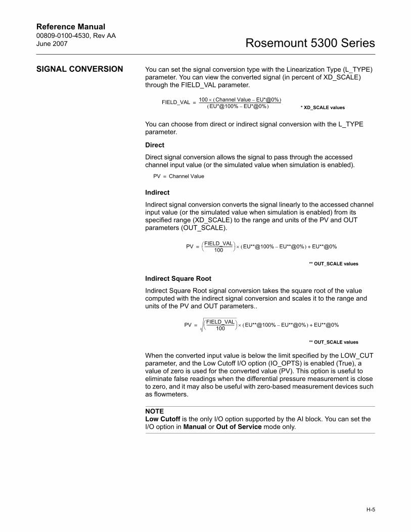
Reference Manual 00809-0100-4530, Rev AAJune 2007 Rosemount 5300 Series
SIGNAL CONVERSION You can set the signal conversion type with the Linearization Type (L_TYPE) parameter. You can view the converted signal (in percent of XD_SCALE) through the FIELD_VAL parameter.
You can choose from direct or indirect signal conversion with the L_TYPE parameter.
Direct
Direct signal conversion allows the signal to pass through the accessed channel input value (or the simulated value when simulation is enabled).
Indirect
Indirect signal conversion converts the signal linearly to the accessed channel input value (or the simulated value when simulation is enabled) from its specified range (XD_SCALE) to the range and units of the PV and OUT parameters (OUT_SCALE).
Indirect Square Root
Indirect Square Root signal conversion takes the square root of the value computed with the indirect signal conversion and scales it to the range and units of the PV and OUT parameters..
When the converted input value is below the limit specified by the LOW_CUT parameter, and the Low Cutoff I/O option (IO_OPTS) is enabled (True), a value of zero is used for the converted value (PV). This option is useful to eliminate false readings when the differential pressure measurement is close to zero, and it may also be useful with zero-based measurement devices such as flowmeters.
NOTELow Cutoff is the only I/O option supported by the AI block. You can set the I/O option in Manual or Out of Service mode only.
FIELD_VAL 100 Channel Value EU*@0%–( )×EU*@100% EU*@0%–( )
--------------------------------------------------------------------------------------------=* XD_SCALE values
PV Channel Value=
PV FIELD_VAL100
-------------------------------⎝ ⎠⎛ ⎞ EU**@100% EU**@0%–( ) EU**@0%+×=
** OUT_SCALE values
PV FIELD_VAL100
-------------------------------⎝ ⎠⎛ ⎞ EU**@100% EU**@0%–( ) EU**@0%+×=
** OUT_SCALE values
H-5
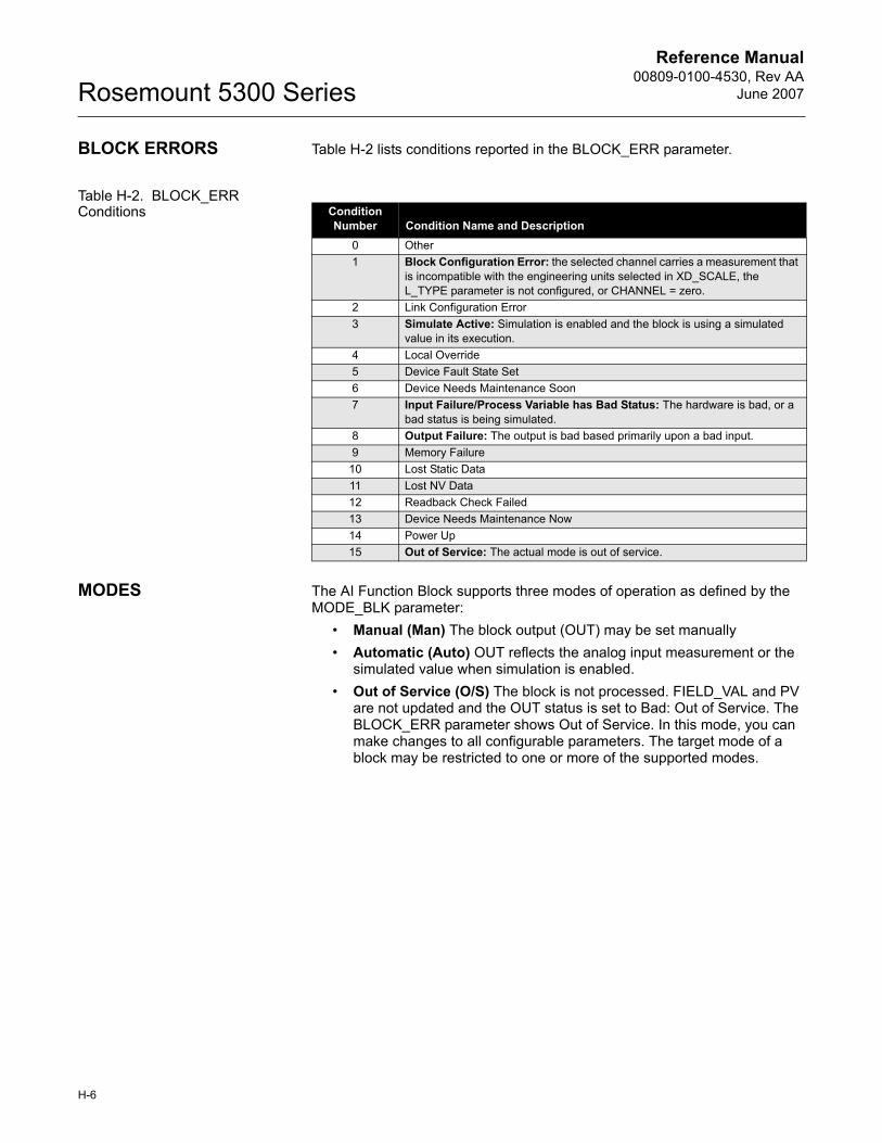
Reference Manual00809-0100-4530, Rev AA
June 2007Rosemount 5300 Series
BLOCK ERRORS Table H-2 lists conditions reported in the BLOCK_ERR parameter.
Table H-2. BLOCK_ERR Conditions
MODES The AI Function Block supports three modes of operation as defined by the MODE_BLK parameter:
� Manual (Man) The block output (OUT) may be set manually� Automatic (Auto) OUT reflects the analog input measurement or the
simulated value when simulation is enabled.� Out of Service (O/S) The block is not processed. FIELD_VAL and PV
are not updated and the OUT status is set to Bad: Out of Service. The BLOCK_ERR parameter shows Out of Service. In this mode, you can make changes to all configurable parameters. The target mode of a block may be restricted to one or more of the supported modes.
Condition Number Condition Name and Description
0 Other1 Block Configuration Error: the selected channel carries a measurement that
is incompatible with the engineering units selected in XD_SCALE, the L_TYPE parameter is not configured, or CHANNEL = zero.
2 Link Configuration Error3 Simulate Active: Simulation is enabled and the block is using a simulated
value in its execution.4 Local Override5 Device Fault State Set6 Device Needs Maintenance Soon7 Input Failure/Process Variable has Bad Status: The hardware is bad, or a
bad status is being simulated.8 Output Failure: The output is bad based primarily upon a bad input.9 Memory Failure
10 Lost Static Data11 Lost NV Data12 Readback Check Failed13 Device Needs Maintenance Now14 Power Up15 Out of Service: The actual mode is out of service.
H-6
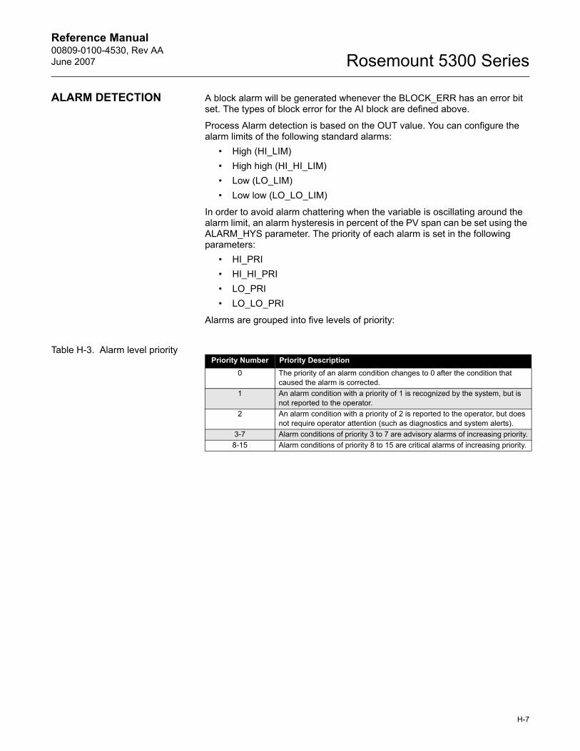
Reference Manual 00809-0100-4530, Rev AAJune 2007 Rosemount 5300 Series
ALARM DETECTION A block alarm will be generated whenever the BLOCK_ERR has an error bit set. The types of block error for the AI block are defined above.
Process Alarm detection is based on the OUT value. You can configure the alarm limits of the following standard alarms:
� High (HI_LIM)� High high (HI_HI_LIM)� Low (LO_LIM)� Low low (LO_LO_LIM)
In order to avoid alarm chattering when the variable is oscillating around the alarm limit, an alarm hysteresis in percent of the PV span can be set using the ALARM_HYS parameter. The priority of each alarm is set in the following parameters:
� HI_PRI� HI_HI_PRI� LO_PRI� LO_LO_PRI
Alarms are grouped into five levels of priority:
Table H-3. Alarm level priorityPriority Number Priority Description
0 The priority of an alarm condition changes to 0 after the condition that caused the alarm is corrected.
1 An alarm condition with a priority of 1 is recognized by the system, but is not reported to the operator.
2 An alarm condition with a priority of 2 is reported to the operator, but does not require operator attention (such as diagnostics and system alerts).
3-7 Alarm conditions of priority 3 to 7 are advisory alarms of increasing priority.8-15 Alarm conditions of priority 8 to 15 are critical alarms of increasing priority.
H-7
Reference Manual00809-0100-4530, Rev AA
June 2007Rosemount 5300 Series
Status Handling Normally, the status of the PV reflects the status of the measurement value, the operating condition of the I/O card, and any active alarm condition. In Auto mode, OUT reflects the value and status quality of the PV. In Man mode, the OUT status constant limit is set to indicate that the value is a constant and the OUT status is Good.
The Uncertain - EU range violation status is always set, and the PV status is set high- or low-limited if the sensor limits for conversion are exceeded.
In the STATUS_OPTS parameter, you can select from the following options to control the status handling:
BAD if Limited � sets the OUT status quality to Bad when the value is higher or lower than the sensor limits.
Uncertain if Limited � sets the OUT status quality to Uncertain when the value is higher or lower than the sensor limits.
Uncertain if in Manual mode � The status of the Output is set to Uncertain when the mode is set to Manual.
NOTESThe instrument must be in Manual or Out of Service mode to set the status option.The AI block only supports the BAD if Limited option. Unsupported options are not grayed out; they appear on the screen in the same manner as supported options.
ADVANCED FEATURES The AI function block provided with Fisher-Rosemount fieldbus devices provides added capability through the addition of the following parameters:
ALARM_TYPE � Allows one or more of the process alarm conditions detected by the AI function block to be used in setting its OUT_D parameter.
OUT_D � Discrete output of the AI function block based on the detection of process alarm condition(s). This parameter may be linked to other function blocks that require a discrete input based on the detected alarm condition.
VAR_SCAN � Time period in seconds over which the variability index (VAR_INDEX) is computed.
VAR_INDEX � Process variability index measured as the integral of average absolute error between PV and its mean value over the previous evaluation period. This index is calculated as a percent of OUT span and is updated at the end of the time period defined by VAR_SCAN.
H-8
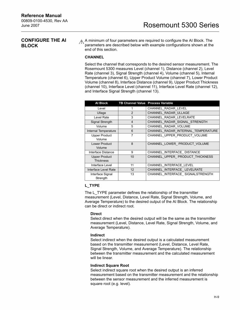
Reference Manual 00809-0100-4530, Rev AAJune 2007 Rosemount 5300 Series
CONFIGURE THE AI BLOCK
A minimum of four parameters are required to configure the AI Block. The parameters are described below with example configurations shown at the end of this section.
CHANNEL
Select the channel that corresponds to the desired sensor measurement. The Rosemount 5300 measures Level (channel 1), Distance (channel 2), Level Rate (channel 3), Signal Strength (channel 4), Volume (channel 5), Internal Temperature (channel 6), Upper Product Volume (channel 7), Lower Product Volume (channel 8), Interface Distance (channel 9), Upper Product Thickness (channel 10), Interface Level (channel 11), Interface Level Rate (channel 12), and Interface Signal Strength (channel 13).
L_TYPE
The L_TYPE parameter defines the relationship of the transmitter measurement (Level, Distance, Level Rate, Signal Strength, Volume, and Average Temperature) to the desired output of the AI Block. The relationship can be direct or indirect root.
DirectSelect direct when the desired output will be the same as the transmitter measurement (Level, Distance, Level Rate, Signal Strength, Volume, and Average Temperature).
IndirectSelect indirect when the desired output is a calculated measurement based on the transmitter measurement (Level, Distance, Level Rate, Signal Strength, Volume, and Average Temperature). The relationship between the transmitter measurement and the calculated measurement will be linear.
Indirect Square RootSelect indirect square root when the desired output is an inferred measurement based on the transmitter measurement and the relationship between the sensor measurement and the inferred measurement is square root (e.g. level).
AI Block TB Channel Value Process VariableLevel 1 CHANNEL_RADAR_LEVELUllage 2 CHANNEL_RADAR_ULLAGE
Level Rate 3 CHANNEL_RADAR_LEVELRATESignal Strength 4 CHANNEL_RADAR_SIGNAL_STRENGTH
Volume 5 CHANNEL_RADAR_VOLUMEInternal Temperature 6 CHANNEL_RADAR_INTERNAL_TEMPERATURE
Upper Product Volume
7 CHANNEL_UPPER_PRODUCT_VOLUME
Lower Product Volume
8 CHANNEL_LOWER_ PRODUCT_VOLUME
Interface Distance 9 CHANNEL_INTERFACE_ DISTANCEUpper Product
Thickness10 CHANNEL_UPPER_ PRODUCT_THICKNESS
Interface Level 11 CHANNEL_INTERFACE_LEVELInterface Level Rate 12 CHANNEL_INTERFACE_ LEVELRATE
Interface Signal Strength
13 CHANNEL_INTERFACE_ SIGNALSTRENGTH
H-9
Reference Manual00809-0100-4530, Rev AA
June 2007Rosemount 5300 Series
XD_SCALE and OUT_SCALE
The XD_SCALE and OUT_SCALE each include three parameters: 0%, 100%, and, engineering units. Set these based on the L_TYPE:
L_TYPE is DirectWhen the desired output is the measured variable, set the XD_SCALE to represent the operating range of the process. Set OUT_SCALE to match XD_SCALE.
L_TYPE is Indirect When an inferred measurement is made based on the sensor measurement, set the XD_SCALE to represent the operating range that the sensor will see in the process. Determine the inferred measurement values that correspond to the XD_SCALE 0 and 100% points and set these for the OUT_SCALE.
L_TYPE is Indirect Square RootWhen an inferred measurement is made based on the transmitter measurement and the relationship between the inferred measurement and sensor measurement is square root, set the XD_SCALE to represent the operating range that the sensor will see in the process. Determine the inferred measurement values that correspond to the XD_SCALE 0 and 100% points and set these for the OUT_SCALE.
H-10

Reference Manual 00809-0100-4530, Rev AAJune 2007 Rosemount 5300 Series
NOTETo avoid configuration errors, only select Engineering Units for XD_SCALE and OUT_SCALE that are supported by the device. The supported units are:
Table H-4. Length
Table H-5. Level Rate
Table H-6. Temperature
Table H-7. Signal Strength
Table H-8. Volume
Display Descriptionm metercm centimetermm millimeterft feetin inch
Display Descriptionm/s meter per secondm/h meter per hourft/s feet per secondin/m inch/minute
Display Description°C Degree Celsius°F Degree Fahrenheit
Display DescriptionmV millivolt
Display Descriptionm3 Cubic meterL Literin3 Cubic inchft3 Cubic feetYd3 Cubic yardGallon US gallonImpGall Imperial gallonbbl barrel
H-11

Reference Manual00809-0100-4530, Rev AA
June 2007Rosemount 5300 Series
H-12

Reference Manual 00809-0100-4530, Rev AAJune 2007 Rosemount 5300 Series
Index
Numerics375 Field Communicator . . . . 5-10751 Field Signal Indicator . . . . 4-14AAddress
Temporary Node . . . . . . . 5-35Agitators . . . . . . . . . . . . . 2-13, 3-8AI Block
Configuration . . . . . . . . . . 5-37Parameters
ALARM_TYPE . . . . . .H-8BLOCK_ERR . . . . . . .H-6IO_OPTS . . . . . . . . . .H-5L_TYPE . . . . . . . . . . .H-5LOW_CUT . . . . . . . . .H-5OUT_D . . . . . . . . . . . .H-8OUT_SCALE . . . . . . .H-5PV_FTIME . . . . . . . . .H-4VAR_INDEX . . . . . . . .H-8VAR_SCAN . . . . . . . .H-8XD_SCALE . . . . . . . .H-5
Status . . . . . . . . . . . . . . . .H-8Alarm Priority . . . . . . . . . . . . . .G-7ALARM_TYPE
AI Block . . . . . . . . . . . . . . .H-8Alarms
Priorety . . . . . . . . . . . . . . .G-7Process . . . . . . . . . . . . . . .G-7
Amplitude Thresholds . . . . . . . . 7-4AMS Suit . . . . . . . . . . . . . 2-6, 5-29Analog Input (AI) Block 5-37, 7-40, H-1
BLOCK_ERR . . . . . . . . . . 7-40Troubleshooting . . . . . . . . 7-40
Analog Input (AI) Function Block 7-40Analog Output
alarm values . . . . . . . . . . . 5-9saturation values . . . . . . . . 5-9
Analog Output calibration . . . . 7-17Anchoring . . . . . . . . . . . . . . . . 3-16Applications . . . . . . . . . . . . . . . 2-2Approval Drawings . . . . . . . . . B-19
BBlock Configuration
AI Block . . . . . . . . . . . . . . 5-37
Block Errors . . . . . . . . . . . . . . 7-40BLOCK_ERR
AI Block . . . . . . . . . .7-40, H-6Resource Block . . . . . . . . 7-39
Bridging . . . . . . . . . . . . . . . . . . 2-10BSP/G threads . . . . . . . . . . . . 3-12Burst Mode . . . . . . . . . . . . . . . 5-45Burst mode . . . . . . . . . . . . . . . 5-44Burst option . . . . . . . . . . . . . . . 5-44
CCable Selection . . . . . . . . . . . . . 4-3Cable/conduit entries . . . . . . . . 4-3Calculation Method . . . . . . . . . 5-34Calibration . . . . . . . . . . . . . . . . 7-18Calibration Offset . . . . . . . . . . .C-3Canadian Standards Association
approval . . . . . . . . . . . . . . B-11Centering Disc . . . . . . . . . . . . 3-19Centering disc . . . . . . . . . . . . . . 3-6Centering piece . . . . . . . . . . . . 3-15Changing the Probe . . . . . . . . 7-29Channel . . . . . . . . . 5-38, D-2, H-9Channel Definitions
Level Transducer Block . . .D-2Coating . . . . . . . . . . . . . . . . . . 2-10COM Port . . . . . . . . . . . . . . . . 5-14Configuration
Analog Input (AI) Function BlockOUT_SCALE .5-39, H-10XD_SCALE . . .5-39, H-10
basic . . . . . . . . . . . . . . . . . 5-3Channel . . . . . . . . . .5-38, H-9Direct . . . . . . . . . . .5-39, H-10Handheld Communicator . 5-10Indirect . . . . . . . . . .5-39, H-10L_TYPE . . . . . . . . . .5-38, H-9
Direct . . . . . . . .5-38, H-9Indirect . 5-38, 5-39, H-9,
H-10volume . . . . . . . . . . . . . . . . 5-6
Current loop resistance . . . . . . . 4-4
DDevice ID . . . . . . . . . . . . . . . . 5-30Device Revision . . . . . . . . . . . 5-11Device Tag . . . . . . . . . . . . . . . 5-35Dielectric Chart . . . . . . . . . . . . 5-23
Dielectric Constant . . . . 5-5, C-10Vapor . . . . . . . . . . . . . . . C-10
Dielectric Constant Calculator .5-23Direct . . . . . 5-38, 5-39, H-9, H-10Direct Signal Conversion . . . . . H-5Display
presentation . . . . . . . . . . . .6-2variables . . . . . . . 5-2, 6-2, 6-3
Display Panel . . . . . . . . . . . . . .6-2Display Panel Variables . . . . . .6-3
EElectrical installation
connecting the transmitter 4-5, 4-8
Intrinsically Safe Output 4-7, 4-12Non-Intrinsically Safe Output 4-6,
4-11Tri-Loop . . . . . . . . . 4-13, 4-14
Emulsion layers . . . . . . . . . . . .2-13European ATEX Directive Information B-3
FFactory Mutual
system control drawing . B-20Field Communicator . . . . . . . .5-10Filtering
AI Block . . . . . . . . . . . . . . H-4Flange Connection . . . . . . . . . .3-3Foam . . . . . . . . . . . . . . . . . . . .2-10Free Space . . . . . . . . . . . . . . . .3-7
GGeometry . . . . . . . . . . . . . . . .5-32Grounding . . . . . . . . . . . . . . . . .4-3
HHART Communicator Menu Tree 5-11Heating Coils . . . . . . . . . . . . . .2-13Heating coils . . . . . . . . . . . . . . .3-8HI_HI_LIM . . . . . . . . . . . . . . . . G-7HI_HI_PRI . . . . . . . . . . . . . . . . G-7HI_LIM . . . . . . . . . . . . . . . . . . . G-7HI_PRI . . . . . . . . . . . . . . . . . . . G-7
www.rosemount.com
Reference Manual00809-0100-4530, Rev AA
June 2007Rosemount 5300 Series
IIndirect . . . .5-38, 5-39, H-9, H-10Indirect Signal Conversion . . . .H-5Installation
cable selection . . . . . . . . . . 4-3cable/conduit entries . . . . . 4-3flange connection . . . . . . . 3-3Free Space . . . . . . . . . . . . 3-7grounding . . . . . . . . . . . . . 4-3mounting considerations . . 3-2mounting position . . . . . . . 3-8power requirements . . 4-4, 4-8procedure . . . . . . . . . . . . 2-14shortening the probe . . . . 3-13Still pipes . . . . . . . . . . . . . . 3-6threaded connection . . . . . 3-2
Interface . . . . . . . . . . . . 2-11, 2-12fully immersed probes . . . 7-16low dielectric constants . . . 7-9
IO_OPTSAI Block . . . . . . . . . . . . . . .H-5
LL_TYPE . . . . . . . . . . . . . 5-38, H-9
. . . . . .5-38, 5-39, H-9, H-10AI Block . . . . . . . . . . . . . . .H-5
LCD . . . . . . . . . . . . . . . . . . . . . 6-3LCD variables . . . . . . . . . . . . . 5-17Level and Distance Calibration 7-18Level Transducer Block . . . . . 5-36
Channel Definitions . . . . . .D-2LO_LIM . . . . . . . . . . . . . . . . . . .G-7LO_LO_LIM . . . . . . . . . . . . . . .G-7LO_LO_PRI . . . . . . . . . . . . . . .G-7LO_PRI . . . . . . . . . . . . . . . . . . .G-7Loop-powered . . . . . . . . . . . . . . 2-6LOW_CUT
AI Block . . . . . . . . . . . . . . .H-5Lower product
dielectric constant . . . . . .C-10Lower Transition Zone . . . . . . . 2-9
MMaximum load resistance . 4-6, 4-7Measurement Mode 5-5, 5-22, 5-32Measurement Principle . . . . . . . 2-1Measuring range . . . . . . . . . . . 2-11Mounting Position . . . . . . . . . . . 3-8Multidrop connection . . . . . . . 5-46Multidrop Mode . . . . . . . . . . . . 5-46
NNAMUR-Compliant Alarm . . . . . 5-9Node Address . . . . . . . . . . . . . 5-35Non-metallic tanks . . . . . . . . . . 3-4
Nozzlemaximum height . . . . . . . . 3-3minimum diameter . . . . . . . 3-3
NPT threads . . . . . . . . . . . . . . 3-12
OOUT_D
AI Block . . . . . . . . . . . . . . .H-8OUT_SCALE . . . . . . . . .5-39, H-10
AI Block . . . . . . . . . . . . . . .H-5L_TYPE
Direct . . . . . . .5-39, H-10Indirect . . . . . .5-39, H-10
PParameter
BLOCK_ERR . . . . . 7-39, 7-40CHANNEL . . . . . . . .5-38, H-9HI_HI_LIM . . . . . . . . . . . . G-7HI_HI_PRI . . . . . . . . . . . . G-7HI_LIM . . . . . . . . . . . . . . . G-7HI_PRI . . . . . . . . . . . . . . . G-7L_TYPE 5-38, 5-39, H-9, H-10LO_LIM . . . . . . . . . . . . . . G-7LO_LO_LIM . . . . . . . . . . . G-7LO_LO_PRI . . . . . . . . . . . G-7LO_PRI . . . . . . . . . . . . . . G-7OUT_SCALE . . . . .5-39, H-10Resource Block . . . . . . . . G-1XD_SCALE . . . . . .5-39, H-10
Pipe InstallationsCentering Disc . . . . . . . . . 3-19
Plate design . . . . . . . . . . . . . . 3-11Poll address . . . . . . . . . . . . . . 5-46Power Requirements . . . . 4-4, 4-8Power supply . . . . . . . . . . . . . . 4-4Probe
anchoring . . . . . . . . . . . . . 3-16changing . . . . . . . . . . . . . 7-29shortening . . . . . . . . . . . . 3-13
Probe End Offset . . . . . . . . . . .C-9Probe End Projection . . . .7-7, C-8Probe Length . . . . 5-4, 5-20, 5-31Probe Type . . . . . . 5-4, 5-20, 5-31Probe types . . . . . . . . . . . . . . . . 2-5Process Alarms . . . . . . . . . . . . G-7Process connection . . . . . . . . . . 3-2Product Certifcates . . . . . . . . . .B-1PV_FTIME
AI Block . . . . . . . . . . . . . . .H-4
RRange Values . . . . . . . . . . . . . . 5-8Rapid Level Changes . . . . . . . . 5-5Recommended mounting position 3-8Register Transducer Block . . . 5-36
Resource Block . . 5-36, 7-39, G-1Block Errors . . . . . . . . . . .7-39Detailed Status . . . . . . . . .7-39Parameters . . . . . . . . . . . G-1
BLOCK_ERR . . . . . .7-39PlantWeb Alerts
Recommended Actions G-8PlantWeb� Alerts . . . . . . G-5
advisory alarms . . . . . G-6failed_alarms . . . . . . G-5maint_alarms . . . . . . G-5
Summary Status . . . . . . .7-39Rosemount 751 . . . . . . . . . . . . .2-6Rosemount Radar Master . . . .5-12RRM . . . . . . . . . . . . . . . . . . . .5-12
COM Port . . . . . . . . . . . . .5-14Setup . . . . . . . . . . . . . . . .5-17
SSignal Conversion
Direct . . . . . . . . . . . . . . . . H-5Indirect . . . . . . . . . . . . . . . H-5
Simulation . . . . . . . . . . . . . . . . H-3Jumper . . . . . . . . . . . . . . . H-3
Spacers . . . . . . . . . . . . . . . . . .3-14Standard Tank Shapes . . . . . . .5-7Status
AI Block . . . . . . . . . . . . . . H-8Strapping Table . . . . . . . . 5-6, 5-34Supported Units . . . . . .5-40, H-11System Architecture . . . . . . . . .2-6
TTag
Device . . . . . . . . . . . . . . .5-35Tank connection . . . . . . . . . . . 3-11
flange . . . . . . . . . . . . . . . . 3-11threaded . . . . . . . . . . . . . .3-12
Tank Environment . . . . . . . . . . .5-5Tank Geometry . . . . . . . . . . . . .5-3Tank Height . . . . . . . . . . . . . . . .5-4Tank shape . . . . . . . . . . . . . . .2-13Tank Shapes . . . . . . . . . . . . . . .5-7Tank Type . . . . . . . . . . . . . . . . .5-6Threaded connection . . . . . . . .3-2Time Domain Reflectometry . . .2-1Transition Zones . . . . . . . . . . . .2-9Transmitter Head
removing . . . . . . . . . . . . .7-28Transmitter housing . . . . . . . . .2-5Transmitter Reference Point . . C-3Tri-Loop . . . . . . . . . . . . . 4-13, 5-44Tri-loop . . . . . . . . . . . . . . . . . . .2-6Trim Near Zone . . . . . . . . . . . . C-4Troubleshooting . . . . . . . . . . .7-30
Analog Input (AI) Block . .7-40Resource Block . . . . . . . .7-39
Index-2
Reference Manual 00809-0100-4530, Rev AAJune 2007
Rosemount 5300 Series
Turbulent conditions . . . . . . . . . 3-8
UUNZ . . . . . . . . . . . . . . . . . 3-3, C-4Upper Null Zone 3-3, 5-8, 5-20, 5-31, C-4Upper Product Dielectric constant 5-5Upper Reference Point . . . 5-4, C-3Upper Transition Zone . . . . . . . 2-9
VVapor . . . . . . . . . . . . . .2-10, C-10VAR_INDEX
AI Block . . . . . . . . . . . . . . .H-8VAR_SCAN
AI Block . . . . . . . . . . . . . . .H-8Vessel characteristics . . . . . . . 2-13Volume Configuration . . . . . . . . 5-6Volume Offset . . . . . . . . . . . . . 5-34
WWaveform plot . . . . . . . . . . . . . .7-3
XXD_SCALE . . . . . . . . . 5-39, H-10
AI Block . . . . . . . . . . . . . . H-5L_TYPE
Direct . . . . . . 5-39, H-10Indirect . . . . . 5-39, H-10
Index-3

Reference Manual00809-0100-4530, Rev AA
June 2007Rosemount 5300 Series
Index-4

Reference Manual 00809-0100-4530, Rev AAJune 2007 Rosemount 5300 Series
Emerson Process Management
© 2007 Rosemount Inc. All rights reserved.
Rosemount 5300 Series Guided Wave Radar Level and Interface Transmitters may be protected by one or more of the following U.S. Patent Nos. xxx and other patents issued or pending in the U.S. and other countries.Rosemount and the Rosemount logotype are registered trademarks of Rosemount Inc.HART is a registered trademark of the HART Communication Foundation.PlantWeb is a registered trademark of one of the Emerson Process Management group of companies.AMS Suite is a trademark of Emerson Process Management.FOUNDATION is a trademark of the Fieldbus Foundation.VITON, and Kalrez are registered trademarks of DuPont Performance Elastomers.Eurofast and Minifast are registered trademarks of Turck Inc.Hastelloy is a registered trademark of Haynes International.Monel is a registered trademark of International Nickel Co.All other marks are the property of their respective owners.
Standard Terms and Conditions of Sale can be found at www.rosemount.com\terms_of_sale.
Rosemount Inc.8200 Market BoulevardChanhassen, MN 55317 USAT (U.S.) 1-800-999-9307T (International) (952) 906-8888F (952) 949-7001
www.rosemount.com
Emerson Process Management Shared Services Ltd.Heath PlaceBognor RegisWest Sussex PO22 9SHEnglandTel 44 (1243) 863121Fax 44 (1243) 867554
Emerson Process Management Asia Pacific Private Limited1 Pandan CrescentSingapore 128461Tel (65) 777-8211Fax (65) [email protected]