Embed Size (px)
Citation preview
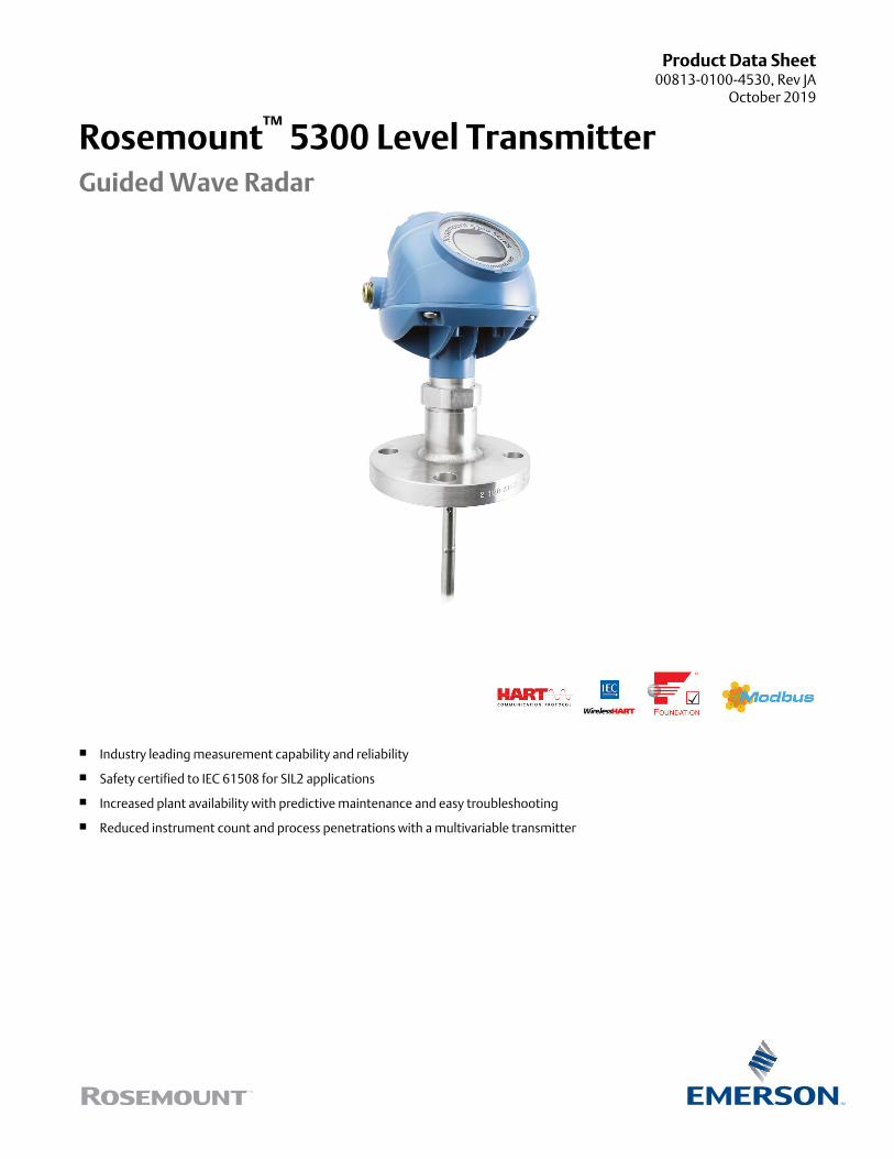
Product Data Sheet00813-0100-4530, Rev JA
October 2019
Rosemount™ 5300 Level TransmitterGuided Wave Radar
Industry leading measurement capability and reliability
Safety certified to IEC 61508 for SIL2 applications
Increased plant availability with predictive maintenance and easy troubleshooting
Reduced instrument count and process penetrations with a multivariable transmitter
Taking guided wave radar benefits to the next level
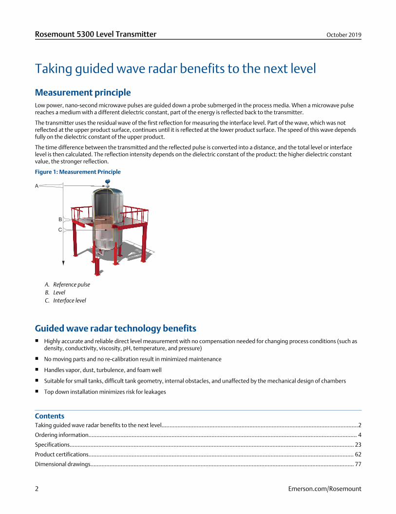
Measurement principleLow power, nano-second microwave pulses are guided down a probe submerged in the process media. When a microwave pulsereaches a medium with a different dielectric constant, part of the energy is reflected back to the transmitter.
The transmitter uses the residual wave of the first reflection for measuring the interface level. Part of the wave, which was notreflected at the upper product surface, continues until it is reflected at the lower product surface. The speed of this wave dependsfully on the dielectric constant of the upper product.
The time difference between the transmitted and the reflected pulse is converted into a distance, and the total level or interfacelevel is then calculated. The reflection intensity depends on the dielectric constant of the product: the higher dielectric constantvalue, the stronger reflection.
Figure 1: Measurement Principle
A. Reference pulseB. LevelC. Interface level
Guided wave radar technology benefits Highly accurate and reliable direct level measurement with no compensation needed for changing process conditions (such as
density, conductivity, viscosity, pH, temperature, and pressure)
No moving parts and no re-calibration result in minimized maintenance
Handles vapor, dust, turbulence, and foam well
Suitable for small tanks, difficult tank geometry, internal obstacles, and unaffected by the mechanical design of chambers
Top down installation minimizes risk for leakages
ContentsTaking guided wave radar benefits to the next level...........................................................................................................................2
Ordering information........................................................................................................................................................................ 4
Specifications.................................................................................................................................................................................. 23
Product certifications...................................................................................................................................................................... 62
Dimensional drawings..................................................................................................................................................................... 77
Rosemount 5300 Level Transmitter October 2019
2 Emerson.com/Rosemount
Special Rosemount 5300 features
Optimized to suit more applications Suitable for most liquid and solids level applications and liquid interface applications
Handles even the most challenging applications reliably, including process vessels, control, and safety systems
Easy retrofit in existing chambers or available as complete assembly with high quality Rosemount chambers
Dynamic Vapor Compensation assures accuracy also in saturated steam
Large coaxial probe optimized for interface applications were there is a need to measure level and interface level all the way upto flange
Best performance and uptime Unique Direct Switch Technology and Probe End Projection improve capability and reliability particularly in challenging
applications
Single lead probe for long measuring ranges, obstructions and low dielectrics ensures reliability in more applications, such asviscous media
Signal processing algorithm makes it possible to distinguish between two liquids with a top layer down to 1 in. (2.5 cm).
Smart Galvanic Interface results in a more stable microwave and EMI performance with minimized effects from outsidedisturbances
Robust design and increased safety Heavy-duty unique hardware for extreme temperature and pressures with multiple layers of protection
EchoLogics® and smart software functions provide enhanced ability to keep track of the surface and detect a full vessel situation
Third party approved for overfill prevention and Safety Integrated System SIL3 suitability
Electronics and cable connections in separate compartments provides safer handling and improved moisture protection
Online device verification and reliable detection of high level conditions with the verification reflector
Easy installation and plant integration Easy upgrade by matching existing tank connections and cut-to-fit probes
Long lengths of rigid probes for robust measurements become cost-effective and practical to ship, store and install with thesegmented probe option (code 4S)
Multivariable device reduces the number of process penetrations
Seamless system integration with HART®, FOUNDATION™ Fieldbus, Modbus®, or IEC 62591 (WirelessHART®) with the EmersonWireless 775 THUM™ Adapter
Pre-configured or easy configuration in Rosemount Radar Master with a five-step wizard, auto connect, and online help
Enhanced DD with step-by-step configuration and echo curve capability in tools such as AMS Device Manager, and handheldcommunicator
DTM™ with echo curve capability for use in FDT®/DTM compatible configuration tools such as PACTware™, YokogawaFieldMate/PRM
Minimized maintenance reduces cost Easy online troubleshooting with user friendly software, utilizing powerful echo curve and logging tools
Signal Quality Metrics diagnostics detect product build-up on probe to monitor turbulence, boiling, foam, and emulsions
Predictive maintenance with advanced diagnostics and Plantweb™ alerts
Modular design for reduced spare parts and easy replacement of the transmitter housing without opening the tank
October 2019 Rosemount 5300 Level Transmitter
Emerson.com/Rosemount 3
Ordering information
Rosemount 5301 and 5302 Level and/or Interface in Liquids
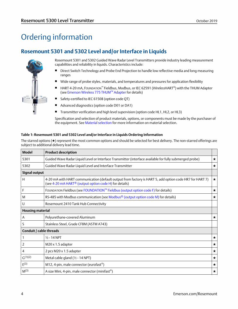
Rosemount 5301 and 5302 Guided Wave Radar Level Transmitters provide industry leading measurementcapabilities and reliability in liquids. Characteristics include:
Direct Switch Technology and Probe End Projection to handle low reflective media and long measuringranges
Wide range of probe styles, materials, and temperatures and pressures for application flexibility
HART 4-20 mA, FOUNDATION™ Fieldbus, Modbus, or IEC 62591 (WirelessHART®) with the THUM Adapter(see Emerson Wireless 775 THUM™ Adapter for details)
Safety-certified to IEC 61508 (option code QT)
Advanced diagnostics (option code D01 or DA1)
Transmitter verification and high level supervision (option code HL1, HL2, or HL3)
Specification and selection of product materials, options, or components must be made by the purchaser ofthe equipment. See Material selection for more information on material selection.
Table 1: Rosemount 5301 and 5302 Level and/or Interface in Liquids Ordering Information
The starred options () represent the most common options and should be selected for best delivery. The non-starred offerings aresubject to additional delivery lead time.
Model Product description
5301 Guided Wave Radar Liquid Level or Interface Transmitter (interface available for fully submerged probe)
5302 Guided Wave Radar Liquid Level and Interface Transmitter
Signal output
H 4-20 mA with HART communication (default output from factory is HART 5, add option code HR7 for HART 7)(see 4-20 mA HART® (output option code H) for details)
F FOUNDATION Fieldbus (see FOUNDATION™ Fieldbus (output option code F) for details)
M RS-485 with Modbus communication (see Modbus® (output option code M) for details)
U Rosemount 2410 Tank Hub Connectivity
Housing material
A Polyurethane-covered Aluminum
S Stainless Steel, Grade CF8M (ASTM A743)
Conduit / cable threads
1 ½ - 14 NPT
2 M20 x 1.5 adapter
4 2 pcs M20 x 1.5 adapter
G(1)(2) Metal cable gland (½ - 14 NPT)
E(3) M12, 4-pin, male connector (eurofast®)
M(3) A size Mini, 4-pin, male connector (minifast®)
Rosemount 5300 Level Transmitter October 2019
4 Emerson.com/Rosemount
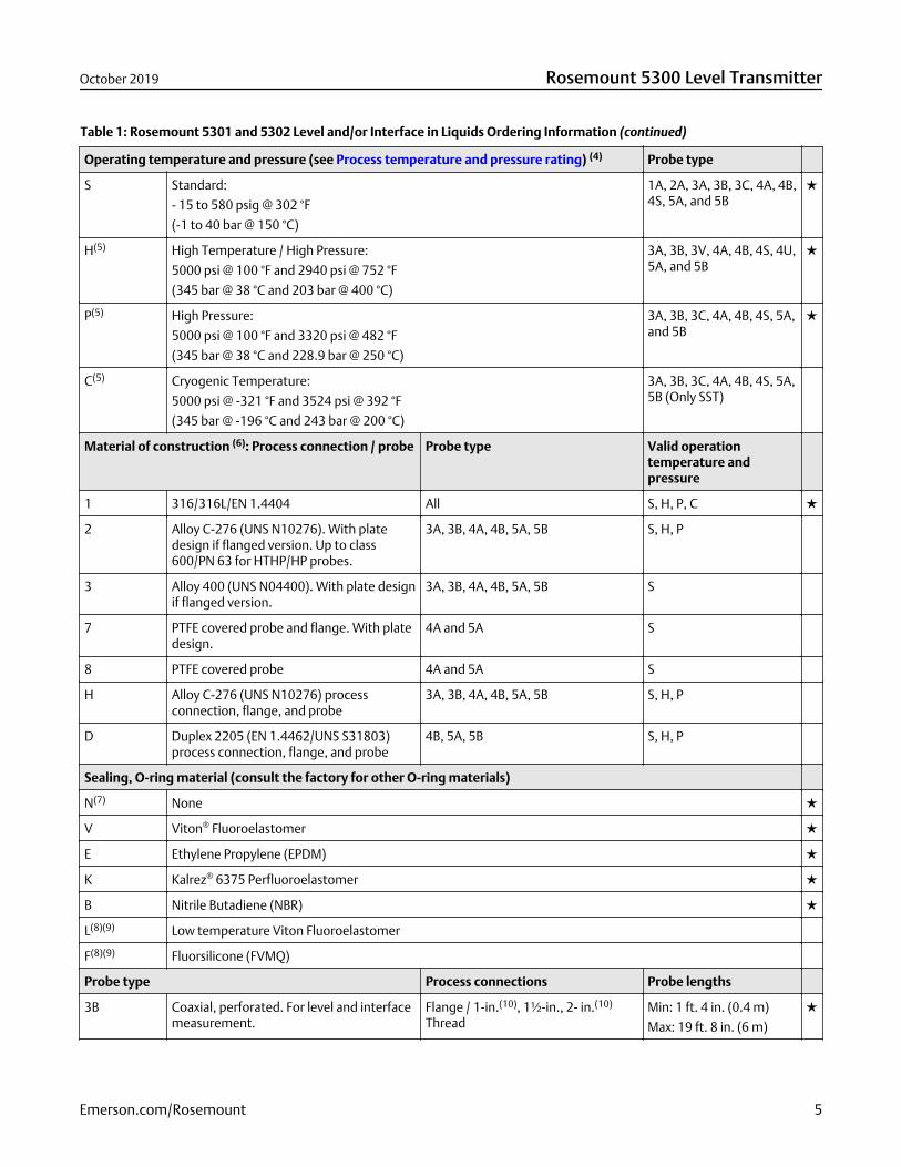
Table 1: Rosemount 5301 and 5302 Level and/or Interface in Liquids Ordering Information (continued)
Operating temperature and pressure (see Process temperature and pressure rating) (4) Probe type
S Standard:
- 15 to 580 psig @ 302 °F
(-1 to 40 bar @ 150 °C)
1A, 2A, 3A, 3B, 3C, 4A, 4B,4S, 5A, and 5B
H(5) High Temperature / High Pressure:
5000 psi @ 100 °F and 2940 psi @ 752 °F
(345 bar @ 38 °C and 203 bar @ 400 °C)
3A, 3B, 3V, 4A, 4B, 4S, 4U,5A, and 5B
P(5) High Pressure:
5000 psi @ 100 °F and 3320 psi @ 482 °F
(345 bar @ 38 °C and 228.9 bar @ 250 °C)
3A, 3B, 3C, 4A, 4B, 4S, 5A,and 5B
C(5) Cryogenic Temperature:
5000 psi @ -321 °F and 3524 psi @ 392 °F
(345 bar @ -196 °C and 243 bar @ 200 °C)
3A, 3B, 3C, 4A, 4B, 4S, 5A,5B (Only SST)
Material of construction (6): Process connection / probe Probe type Valid operationtemperature andpressure
1 316/316L/EN 1.4404 All S, H, P, C
2 Alloy C-276 (UNS N10276). With platedesign if flanged version. Up to class600/PN 63 for HTHP/HP probes.
3A, 3B, 4A, 4B, 5A, 5B S, H, P
3 Alloy 400 (UNS N04400). With plate designif flanged version.
3A, 3B, 4A, 4B, 5A, 5B S
7 PTFE covered probe and flange. With platedesign.
4A and 5A S
8 PTFE covered probe 4A and 5A S
H Alloy C-276 (UNS N10276) processconnection, flange, and probe
3A, 3B, 4A, 4B, 5A, 5B S, H, P
D Duplex 2205 (EN 1.4462/UNS S31803)process connection, flange, and probe
4B, 5A, 5B S, H, P
Sealing, O-ring material (consult the factory for other O-ring materials)
N(7) None
V Viton® Fluoroelastomer
E Ethylene Propylene (EPDM)
K Kalrez® 6375 Perfluoroelastomer
B Nitrile Butadiene (NBR)
L(8)(9) Low temperature Viton Fluoroelastomer
F(8)(9) Fluorsilicone (FVMQ)
Probe type Process connections Probe lengths
3B Coaxial, perforated. For level and interfacemeasurement.
Flange / 1-in.(10), 1½-in., 2- in.(10)
ThreadMin: 1 ft. 4 in. (0.4 m)
Max: 19 ft. 8 in. (6 m)
October 2019 Rosemount 5300 Level Transmitter
Emerson.com/Rosemount 5
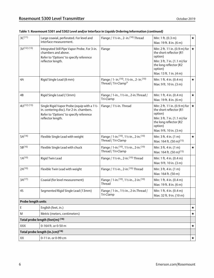
Table 1: Rosemount 5301 and 5302 Level and/or Interface in Liquids Ordering Information (continued)
3C(11) Large coaxial, perforated. For level andinterface measurement.
Flange / 1½-in., 2- in.(10) Thread Min: 1 ft. (0.3 m)
Max: 19 ft. 8 in. (6 m)
3V(12) (13) Integrated Still Pipe Vapor Probe. For 3-in.chambers and above.
Refer to "Options" to specify referencereflector length.
Flange Min: 2 ft. 11 in. (0.9 m) forthe short reflector (R1option)
Min: 3 ft. 7 in. (1.1 m) forthe long reflector (R2option)
Max: 13 ft. 1 in. (4 m)
4A Rigid Single Lead (8 mm) Flange / 1- in.(10), 1½-in., 2- in.(10)
Thread / Tri-Clamp®Min: 1 ft. 4 in. (0.4 m)
Max: 9 ft. 10 in. (3 m)
4B Rigid Single Lead (13mm) Flange / 1-in., 1½-in., 2-in.Thread /Tri-Clamp
Min: 1 ft. 4 in. (0.4 m)
Max: 19 ft. 8 in. (6 m)
4U(12) (13) Single Rigid Vapor Probe (equip with a 1½-in. centering disc). For 2-in. chambers.
Refer to "Options" to specify referencereflector length.
Flange / 1½-in. Thread Min: 2 ft. 11 in. (0.9 m) forthe short reflector (R1option)
Min: 3 ft. 7 in. (1.1 m) forthe long reflector (R2option)
Max: 9 ft. 10 in. (3 m)
5A(14) Flexible Single Lead with weight Flange / 1-in.(10), 1½-in., 2-in.(10)
Thread / Tri-ClampMin: 3 ft. 4 in. (1 m)
Max: 164 ft. (50 m)(15)
5B(16) Flexible Single Lead with chuck Flange / 1-in.(10), 1½-in., 2-in.(10)
Thread / Tri-ClampMin: 3 ft. 4 in. (1 m)
Max: 164 ft. (50 m)(15)
1A(10) Rigid Twin Lead Flange / 1½-in., 2-in.(10) Thread Min: 1 ft. 4 in. (0.4 m)
Max: 9 ft. 10 in. (3 m)
2A(10) Flexible Twin Lead with weight Flange / 1½-in., 2-in.(10) Thread Min: 3 ft. 4 in. (1 m)
Max: 164 ft. (50 m)
3A(17) Coaxial (for level measurement) Flange / 1-in.(10), 1½-in., 2-in.(10)
ThreadMin: 1 ft. 4 in. (0.4 m)
Max: 19 ft. 8 in. (6 m)
4S Segmented Rigid Single Lead (13mm) Flange / 1-in., 1½-in., 2-in.Thread /Tri-Clamp
Min: 1 ft. 4 in. (0.4 m)
Max: 32 ft. 9 in. (10 m)
Probe length units
E English (feet, in.)
M Metric (meters, centimeters)
Total probe length (feet/m) (18)
XXX 0-164 ft. or 0-50 m
Total probe length (in./cm)(18)
XX 0-11 in. or 0-99 cm
Rosemount 5300 Level Transmitter October 2019
6 Emerson.com/Rosemount

Table 1: Rosemount 5301 and 5302 Level and/or Interface in Liquids Ordering Information (continued)
Process connection - size / type (consult the factory for other process connections)
ASME flanges Material of construction Operating temperatureand pressure
AA 2-in. Class 150, RF (Raised Face Type) 1, 2, 3, 7, 8, H, D S, H, P, C
AB 2-in. Class 300, RF (Raised Face Type) 1, 2, 3, 7, 8, H, D S, H, P, C
AC 2-in. Class 600, RF (Raised Face Type) 1, 2, H, D H, P, C
AD 2-in. Class 900, RF (Raised Face Type) 1, H, D H, P, C
BA 3-in. Class 150, RF (Raised Face Type) 1, 2, 3, 7, 8, H, D S, H, P, C
BB 3-in. Class 300, RF (Raised Face Type) 1, 2, 3, 7, 8, H, D S, H, P, C
BC 3-in. Class 600, RF (Raised Face Type) 1, 2, H, D H, P, C
BD 3-in. Class 900, RF (Raised Face Type) 1, H, D H, P, C
CA 4-in. Class 150, RF (Raised Face Type) 1, 2, 3, 7, 8, H, D S, H, P, C
CB 4-in. Class 300, RF (Raised Face Type) 1, 2, 3, 7, 8, H, D S, H, P, C
CC 4-in. Class 600, RF (Raised Face Type) 1, 2, H, D H, P, C
CD 4-in. Class 900, RF (Raised Face Type) 1, H, D H, P, C
AE 2-in. Class 1500, RF (Raised Face Type) 1, H, D H, P, C
AF 2-in. Class 2500, RF (Raised Face Type) 1 H, P, C
AI 2-in. Class 600, RTJ (Ring Type Joint) 1, H, D H, P, C
AJ 2-in. Class 900, RTJ (Ring Type Joint) 1, H, D H, P, C
AK 2-in. Class 1500, RTJ (Ring Type Joint) 1, H, D H, P, C
BE 3-in. Class 1500, RF (Raised Face Type) 1, H, D H, P, C
BF 3-in. Class 2500, RF (Raised Face Type) 1 H, P, C
BI 3-in. Class 600, RTJ (Ring Type Joint) 1, H, D H, P, C
BJ 3-in. Class 900, RTJ (Ring Type Joint) 1, H, D H, P, C
BK 3-in. Class 1500, RTJ (Ring Type Joint) 1, H, D H, P, C
CE 4-in. Class 1500, RF (Raised Face Type) 1, H, D H, P, C
CF 4-in. Class 2500, RF (Raised Face Type) 1 H, P, C
CI 4-in. Class 600, RTJ (Ring Type Joint) 1, H, D H, P, C
CJ 4-in. Class 900, RTJ (Ring Type Joint) 1, H, D H, P, C
CK 4-in. Class 1500, RTJ (Ring Type Joint) 1, H, D H, P, C
DA 6-in. Class 150, RF (Raised Face Type) 1, 2, 3, 7, 8, H S, H, P, C
EN 1092-1 flanges Material of construction Operating temperatureand pressure
HB DN50, PN40, Type A flat face 1, 2, 3, 7, 8 S, H, P, C
HC DN50, PN63, Type A flat face 1, 2, 3 H, P, C
HD DN50, PN100, Type A flat face 1 H, P, C
IA DN80, PN16, Type A flat face 1, 2, 3, 7, 8 S, H, P, C
October 2019 Rosemount 5300 Level Transmitter
Emerson.com/Rosemount 7
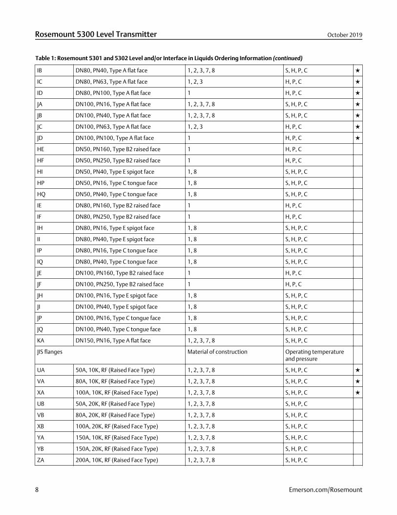
Table 1: Rosemount 5301 and 5302 Level and/or Interface in Liquids Ordering Information (continued)
IB DN80, PN40, Type A flat face 1, 2, 3, 7, 8 S, H, P, C
IC DN80, PN63, Type A flat face 1, 2, 3 H, P, C
ID DN80, PN100, Type A flat face 1 H, P, C
JA DN100, PN16, Type A flat face 1, 2, 3, 7, 8 S, H, P, C
JB DN100, PN40, Type A flat face 1, 2, 3, 7, 8 S, H, P, C
JC DN100, PN63, Type A flat face 1, 2, 3 H, P, C
JD DN100, PN100, Type A flat face 1 H, P, C
HE DN50, PN160, Type B2 raised face 1 H, P, C
HF DN50, PN250, Type B2 raised face 1 H, P, C
HI DN50, PN40, Type E spigot face 1, 8 S, H, P, C
HP DN50, PN16, Type C tongue face 1, 8 S, H, P, C
HQ DN50, PN40, Type C tongue face 1, 8 S, H, P, C
IE DN80, PN160, Type B2 raised face 1 H, P, C
IF DN80, PN250, Type B2 raised face 1 H, P, C
IH DN80, PN16, Type E spigot face 1, 8 S, H, P, C
II DN80, PN40, Type E spigot face 1, 8 S, H, P, C
IP DN80, PN16, Type C tongue face 1, 8 S, H, P, C
IQ DN80, PN40, Type C tongue face 1, 8 S, H, P, C
JE DN100, PN160, Type B2 raised face 1 H, P, C
JF DN100, PN250, Type B2 raised face 1 H, P, C
JH DN100, PN16, Type E spigot face 1, 8 S, H, P, C
JI DN100, PN40, Type E spigot face 1, 8 S, H, P, C
JP DN100, PN16, Type C tongue face 1, 8 S, H, P, C
JQ DN100, PN40, Type C tongue face 1, 8 S, H, P, C
KA DN150, PN16, Type A flat face 1, 2, 3, 7, 8 S, H, P, C
JIS flanges Material of construction Operating temperatureand pressure
UA 50A, 10K, RF (Raised Face Type) 1, 2, 3, 7, 8 S, H, P, C
VA 80A, 10K, RF (Raised Face Type) 1, 2, 3, 7, 8 S, H, P, C
XA 100A, 10K, RF (Raised Face Type) 1, 2, 3, 7, 8 S, H, P, C
UB 50A, 20K, RF (Raised Face Type) 1, 2, 3, 7, 8 S, H, P, C
VB 80A, 20K, RF (Raised Face Type) 1, 2, 3, 7, 8 S, H, P, C
XB 100A, 20K, RF (Raised Face Type) 1, 2, 3, 7, 8 S, H, P, C
YA 150A, 10K, RF (Raised Face Type) 1, 2, 3, 7, 8 S, H, P, C
YB 150A, 20K, RF (Raised Face Type) 1, 2, 3, 7, 8 S, H, P, C
ZA 200A, 10K, RF (Raised Face Type) 1, 2, 3, 7, 8 S, H, P, C
Rosemount 5300 Level Transmitter October 2019
8 Emerson.com/Rosemount
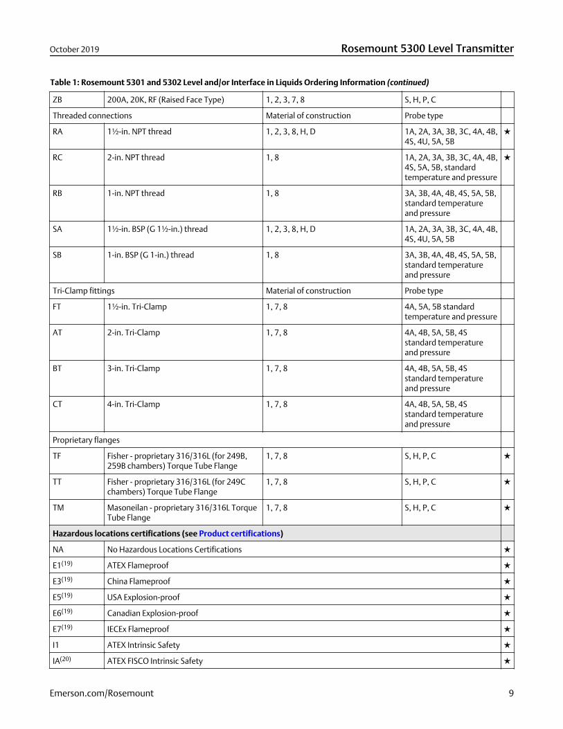
Table 1: Rosemount 5301 and 5302 Level and/or Interface in Liquids Ordering Information (continued)
ZB 200A, 20K, RF (Raised Face Type) 1, 2, 3, 7, 8 S, H, P, C
Threaded connections Material of construction Probe type
RA 1½-in. NPT thread 1, 2, 3, 8, H, D 1A, 2A, 3A, 3B, 3C, 4A, 4B,4S, 4U, 5A, 5B
RC 2-in. NPT thread 1, 8 1A, 2A, 3A, 3B, 3C, 4A, 4B,4S, 5A, 5B, standardtemperature and pressure
RB 1-in. NPT thread 1, 8 3A, 3B, 4A, 4B, 4S, 5A, 5B,standard temperatureand pressure
SA 1½-in. BSP (G 1½-in.) thread 1, 2, 3, 8, H, D 1A, 2A, 3A, 3B, 3C, 4A, 4B,4S, 4U, 5A, 5B
SB 1-in. BSP (G 1-in.) thread 1, 8 3A, 3B, 4A, 4B, 4S, 5A, 5B,standard temperatureand pressure
Tri-Clamp fittings Material of construction Probe type
FT 1½-in. Tri-Clamp 1, 7, 8 4A, 5A, 5B standardtemperature and pressure
AT 2-in. Tri-Clamp 1, 7, 8 4A, 4B, 5A, 5B, 4Sstandard temperatureand pressure
BT 3-in. Tri-Clamp 1, 7, 8 4A, 4B, 5A, 5B, 4Sstandard temperatureand pressure
CT 4-in. Tri-Clamp 1, 7, 8 4A, 4B, 5A, 5B, 4Sstandard temperatureand pressure
Proprietary flanges
TF Fisher - proprietary 316/316L (for 249B,259B chambers) Torque Tube Flange
1, 7, 8 S, H, P, C
TT Fisher - proprietary 316/316L (for 249Cchambers) Torque Tube Flange
1, 7, 8 S, H, P, C
TM Masoneilan - proprietary 316/316L TorqueTube Flange
1, 7, 8 S, H, P, C
Hazardous locations certifications (see Product certifications)
NA No Hazardous Locations Certifications
E1(19) ATEX Flameproof
E3(19) China Flameproof
E5(19) USA Explosion-proof
E6(19) Canadian Explosion-proof
E7(19) IECEx Flameproof
I1 ATEX Intrinsic Safety
IA(20) ATEX FISCO Intrinsic Safety
October 2019 Rosemount 5300 Level Transmitter
Emerson.com/Rosemount 9
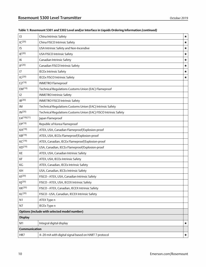
Table 1: Rosemount 5301 and 5302 Level and/or Interface in Liquids Ordering Information (continued)
I3 China Intrinsic Safety
IC(20) China FISCO Intrinsic Safety
I5 USA Intrinsic Safety and Non-Incendive
IE(20) USA FISCO Intrinsic Safety
I6 Canadian Intrinsic Safety
IF(20) Canadian FISCO Intrinsic Safety
I7 IECEx Intrinsic Safety
IG(20) IECEx FISCO Intrinsic Safety
E2(19) INMETRO Flameproof
EM(19) Technical Regulations Customs Union (EAC) Flameproof
I2 INMETRO Intrinsic Safety
IB(20) INMETRO FISCO Intrinsic Safety
IM Technical Regulations Customs Union (EAC) Intrinsic Safety
IN(20) Technical Regulations Customs Union (EAC) FISCO Intrinsic Safety
E4(19)(21) Japan Flameproof
EP(19) Republic of Korea Flameproof
KA(19) ATEX, USA, Canadian Flameproof/Explosion-proof
KB(19) ATEX, USA, IECEx Flameproof/Explosion-proof
KC(19) ATEX, Canadian, IECEx Flameproof/Explosion-proof
KD(19) USA, Canadian, IECEx Flameproof/Explosion-proof
KE ATEX, USA, Canadian Intrinsic Safety
KF ATEX, USA, IECEx Intrinsic Safety
KG ATEX, Canadian, IECEx Intrinsic Safety
KH USA, Canadian, IECEx Intrinsic Safety
KI(20) FISCO - ATEX, USA, Canadian Intrinsic Safety
KJ(20) FISCO - ATEX, USA, IECEX Intrinsic Safety
KK(20) FISCO - ATEX, Canadian, IECEX Intrinsic Safety
KL(20) FISCO - USA, Canadian, IECEX Intrinsic Safety
N1 ATEX Type n
N7 IECEx Type n
Options (include with selected model number)
Display
M1 Integral digital display
Communication
HR7 4–20 mA with digital signal based on HART 7 protocol
Rosemount 5300 Level Transmitter October 2019
10 Emerson.com/Rosemount
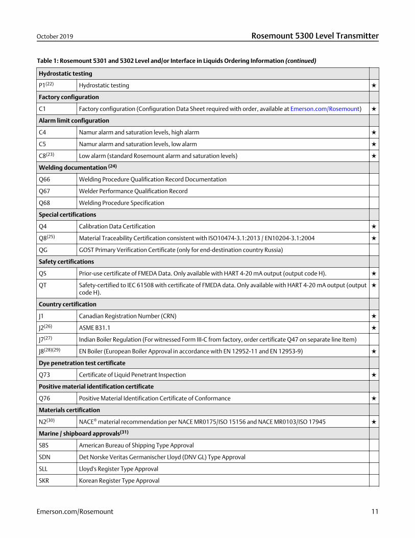
Table 1: Rosemount 5301 and 5302 Level and/or Interface in Liquids Ordering Information (continued)
Hydrostatic testing
P1(22) Hydrostatic testing
Factory configuration
C1 Factory configuration (Configuration Data Sheet required with order, available at Emerson.com/Rosemount)
Alarm limit configuration
C4 Namur alarm and saturation levels, high alarm
C5 Namur alarm and saturation levels, low alarm
C8(23) Low alarm (standard Rosemount alarm and saturation levels)
Welding documentation (24)
Q66 Welding Procedure Qualification Record Documentation
Q67 Welder Performance Qualification Record
Q68 Welding Procedure Specification
Special certifications
Q4 Calibration Data Certification
Q8(25) Material Traceability Certification consistent with ISO10474-3.1:2013 / EN10204-3.1:2004
QG GOST Primary Verification Certificate (only for end-destination country Russia)
Safety certifications
QS Prior-use certificate of FMEDA Data. Only available with HART 4-20 mA output (output code H).
QT Safety-certified to IEC 61508 with certificate of FMEDA data. Only available with HART 4-20 mA output (outputcode H).
Country certification
J1 Canadian Registration Number (CRN)
J2(26) ASME B31.1
J7(27) Indian Boiler Regulation (For witnessed Form III-C from factory, order certificate Q47 on separate line Item)
J8(28)(29) EN Boiler (European Boiler Approval in accordance with EN 12952-11 and EN 12953-9)
Dye penetration test certificate
Q73 Certificate of Liquid Penetrant Inspection
Positive material identification certificate
Q76 Positive Material Identification Certificate of Conformance
Materials certification
N2(30) NACE® material recommendation per NACE MR0175/ISO 15156 and NACE MR0103/ISO 17945
Marine / shipboard approvals(31)
SBS American Bureau of Shipping Type Approval
SDN Det Norske Veritas Germanischer Lloyd (DNV GL) Type Approval
SLL Lloyd's Register Type Approval
SKR Korean Register Type Approval
October 2019 Rosemount 5300 Level Transmitter
Emerson.com/Rosemount 11
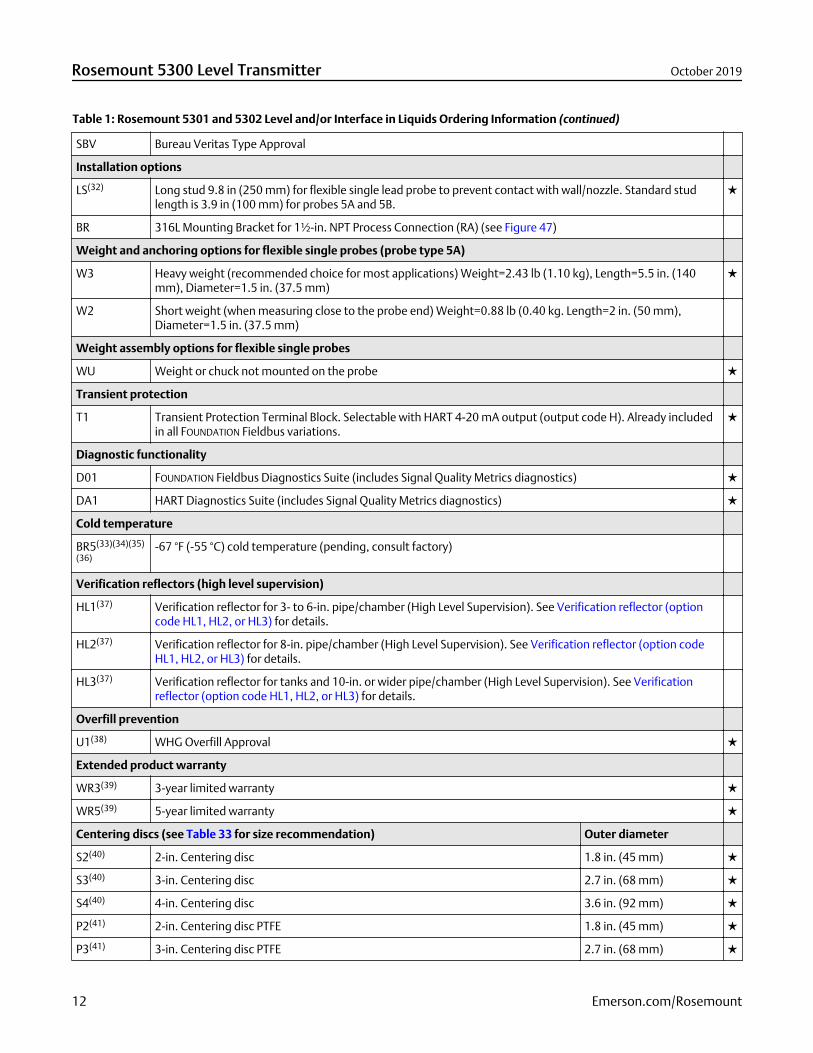
Table 1: Rosemount 5301 and 5302 Level and/or Interface in Liquids Ordering Information (continued)
SBV Bureau Veritas Type Approval
Installation options
LS(32) Long stud 9.8 in (250 mm) for flexible single lead probe to prevent contact with wall/nozzle. Standard studlength is 3.9 in (100 mm) for probes 5A and 5B.
BR 316L Mounting Bracket for 1½-in. NPT Process Connection (RA) (see Figure 47)
Weight and anchoring options for flexible single probes (probe type 5A)
W3 Heavy weight (recommended choice for most applications) Weight=2.43 lb (1.10 kg), Length=5.5 in. (140mm), Diameter=1.5 in. (37.5 mm)
W2 Short weight (when measuring close to the probe end) Weight=0.88 lb (0.40 kg. Length=2 in. (50 mm),Diameter=1.5 in. (37.5 mm)
Weight assembly options for flexible single probes
WU Weight or chuck not mounted on the probe
Transient protection
T1 Transient Protection Terminal Block. Selectable with HART 4-20 mA output (output code H). Already includedin all FOUNDATION Fieldbus variations.
Diagnostic functionality
D01 FOUNDATION Fieldbus Diagnostics Suite (includes Signal Quality Metrics diagnostics)
DA1 HART Diagnostics Suite (includes Signal Quality Metrics diagnostics)
Cold temperature
BR5(33)(34)(35)
(36)-67 °F (-55 °C) cold temperature (pending, consult factory)
Verification reflectors (high level supervision)
HL1(37) Verification reflector for 3- to 6-in. pipe/chamber (High Level Supervision). See Verification reflector (optioncode HL1, HL2, or HL3) for details.
HL2(37) Verification reflector for 8-in. pipe/chamber (High Level Supervision). See Verification reflector (option codeHL1, HL2, or HL3) for details.
HL3(37) Verification reflector for tanks and 10-in. or wider pipe/chamber (High Level Supervision). See Verificationreflector (option code HL1, HL2, or HL3) for details.
Overfill prevention
U1(38) WHG Overfill Approval
Extended product warranty
WR3(39) 3-year limited warranty
WR5(39) 5-year limited warranty
Centering discs (see Table 33 for size recommendation) Outer diameter
S2(40) 2-in. Centering disc 1.8 in. (45 mm)
S3(40) 3-in. Centering disc 2.7 in. (68 mm)
S4(40) 4-in. Centering disc 3.6 in. (92 mm)
P2(41) 2-in. Centering disc PTFE 1.8 in. (45 mm)
P3(41) 3-in. Centering disc PTFE 2.7 in. (68 mm)
Rosemount 5300 Level Transmitter October 2019
12 Emerson.com/Rosemount
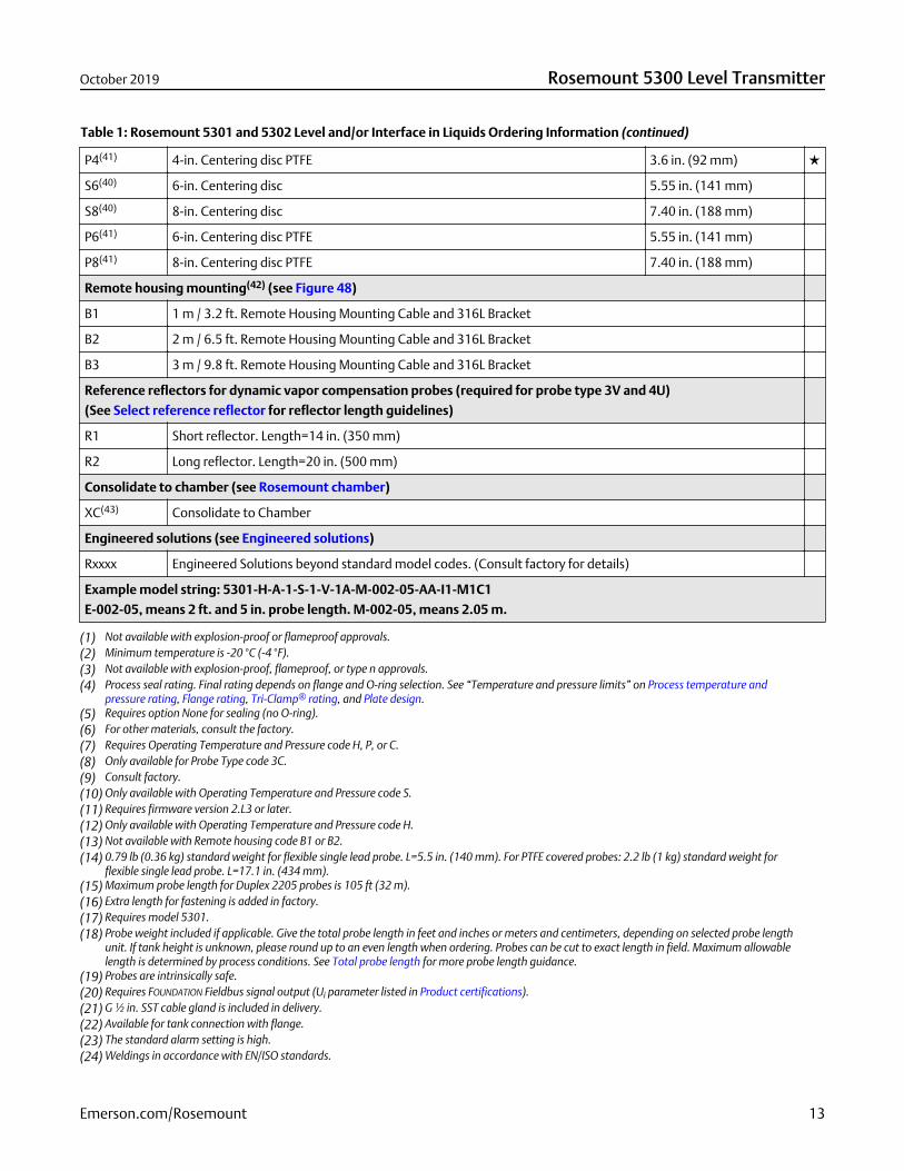
Table 1: Rosemount 5301 and 5302 Level and/or Interface in Liquids Ordering Information (continued)
P4(41) 4-in. Centering disc PTFE 3.6 in. (92 mm)
S6(40) 6-in. Centering disc 5.55 in. (141 mm)
S8(40) 8-in. Centering disc 7.40 in. (188 mm)
P6(41) 6-in. Centering disc PTFE 5.55 in. (141 mm)
P8(41) 8-in. Centering disc PTFE 7.40 in. (188 mm)
Remote housing mounting(42) (see Figure 48)
B1 1 m / 3.2 ft. Remote Housing Mounting Cable and 316L Bracket
B2 2 m / 6.5 ft. Remote Housing Mounting Cable and 316L Bracket
B3 3 m / 9.8 ft. Remote Housing Mounting Cable and 316L Bracket
Reference reflectors for dynamic vapor compensation probes (required for probe type 3V and 4U)
(See Select reference reflector for reflector length guidelines)
R1 Short reflector. Length=14 in. (350 mm)
R2 Long reflector. Length=20 in. (500 mm)
Consolidate to chamber (see Rosemount chamber)
XC(43) Consolidate to Chamber
Engineered solutions (see Engineered solutions)
Rxxxx Engineered Solutions beyond standard model codes. (Consult factory for details)
Example model string: 5301-H-A-1-S-1-V-1A-M-002-05-AA-I1-M1C1
E-002-05, means 2 ft. and 5 in. probe length. M-002-05, means 2.05 m.
(1) Not available with explosion-proof or flameproof approvals.(2) Minimum temperature is -20 °C (-4 °F).(3) Not available with explosion-proof, flameproof, or type n approvals.(4) Process seal rating. Final rating depends on flange and O-ring selection. See “Temperature and pressure limits” on Process temperature and
pressure rating, Flange rating, Tri-Clamp® rating, and Plate design.(5) Requires option None for sealing (no O-ring).(6) For other materials, consult the factory.(7) Requires Operating Temperature and Pressure code H, P, or C.(8) Only available for Probe Type code 3C.(9) Consult factory.(10) Only available with Operating Temperature and Pressure code S.(11) Requires firmware version 2.L3 or later.(12) Only available with Operating Temperature and Pressure code H.(13) Not available with Remote housing code B1 or B2.(14) 0.79 lb (0.36 kg) standard weight for flexible single lead probe. L=5.5 in. (140 mm). For PTFE covered probes: 2.2 lb (1 kg) standard weight for
flexible single lead probe. L=17.1 in. (434 mm).(15) Maximum probe length for Duplex 2205 probes is 105 ft (32 m).(16) Extra length for fastening is added in factory.(17) Requires model 5301.(18) Probe weight included if applicable. Give the total probe length in feet and inches or meters and centimeters, depending on selected probe length
unit. If tank height is unknown, please round up to an even length when ordering. Probes can be cut to exact length in field. Maximum allowablelength is determined by process conditions. See Total probe length for more probe length guidance.
(19) Probes are intrinsically safe.(20) Requires FOUNDATION Fieldbus signal output (Ui parameter listed in Product certifications).(21) G ½ in. SST cable gland is included in delivery.(22) Available for tank connection with flange.(23) The standard alarm setting is high.(24) Weldings in accordance with EN/ISO standards.
October 2019 Rosemount 5300 Level Transmitter
Emerson.com/Rosemount 13
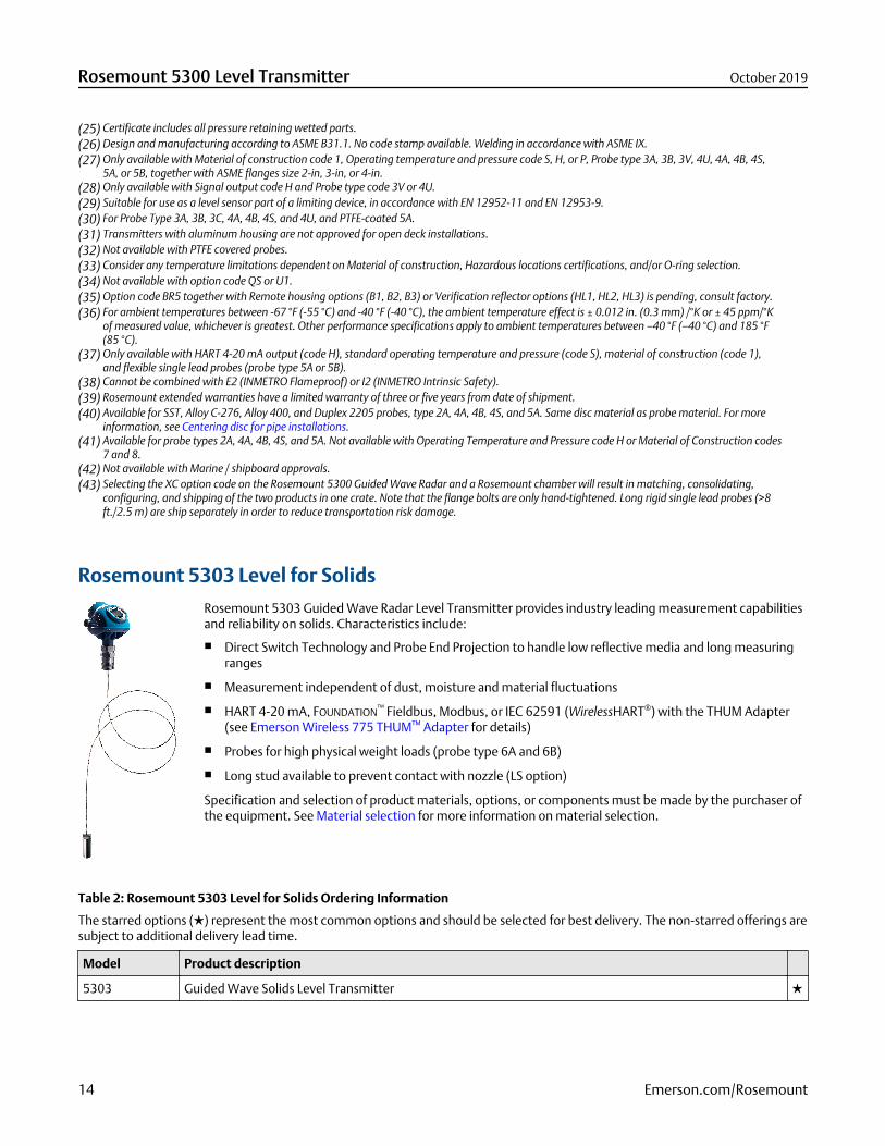
(25) Certificate includes all pressure retaining wetted parts.(26) Design and manufacturing according to ASME B31.1. No code stamp available. Welding in accordance with ASME IX.(27) Only available with Material of construction code 1, Operating temperature and pressure code S, H, or P, Probe type 3A, 3B, 3V, 4U, 4A, 4B, 4S,
5A, or 5B, together with ASME flanges size 2-in, 3-in, or 4-in.(28) Only available with Signal output code H and Probe type code 3V or 4U.(29) Suitable for use as a level sensor part of a limiting device, in accordance with EN 12952-11 and EN 12953-9.(30) For Probe Type 3A, 3B, 3C, 4A, 4B, 4S, and 4U, and PTFE-coated 5A.(31) Transmitters with aluminum housing are not approved for open deck installations.(32) Not available with PTFE covered probes.(33) Consider any temperature limitations dependent on Material of construction, Hazardous locations certifications, and/or O-ring selection.(34) Not available with option code QS or U1.(35) Option code BR5 together with Remote housing options (B1, B2, B3) or Verification reflector options (HL1, HL2, HL3) is pending, consult factory.(36) For ambient temperatures between -67 °F (-55 °C) and -40 °F (-40 °C), the ambient temperature effect is ± 0.012 in. (0.3 mm) /°K or ± 45 ppm/°K
of measured value, whichever is greatest. Other performance specifications apply to ambient temperatures between –40 °F (–40 °C) and 185 °F(85 °C).
(37) Only available with HART 4-20 mA output (code H), standard operating temperature and pressure (code S), material of construction (code 1),and flexible single lead probes (probe type 5A or 5B).
(38) Cannot be combined with E2 (INMETRO Flameproof) or I2 (INMETRO Intrinsic Safety).(39) Rosemount extended warranties have a limited warranty of three or five years from date of shipment.(40) Available for SST, Alloy C-276, Alloy 400, and Duplex 2205 probes, type 2A, 4A, 4B, 4S, and 5A. Same disc material as probe material. For more
information, see Centering disc for pipe installations.(41) Available for probe types 2A, 4A, 4B, 4S, and 5A. Not available with Operating Temperature and Pressure code H or Material of Construction codes
7 and 8.(42) Not available with Marine / shipboard approvals.(43) Selecting the XC option code on the Rosemount 5300 Guided Wave Radar and a Rosemount chamber will result in matching, consolidating,
configuring, and shipping of the two products in one crate. Note that the flange bolts are only hand-tightened. Long rigid single lead probes (>8ft./2.5 m) are ship separately in order to reduce transportation risk damage.
Rosemount 5303 Level for Solids
Rosemount 5303 Guided Wave Radar Level Transmitter provides industry leading measurement capabilitiesand reliability on solids. Characteristics include:
Direct Switch Technology and Probe End Projection to handle low reflective media and long measuringranges
Measurement independent of dust, moisture and material fluctuations
HART 4-20 mA, FOUNDATION™ Fieldbus, Modbus, or IEC 62591 (WirelessHART®) with the THUM Adapter(see Emerson Wireless 775 THUM™ Adapter for details)
Probes for high physical weight loads (probe type 6A and 6B)
Long stud available to prevent contact with nozzle (LS option)
Specification and selection of product materials, options, or components must be made by the purchaser ofthe equipment. See Material selection for more information on material selection.
Table 2: Rosemount 5303 Level for Solids Ordering Information
The starred options () represent the most common options and should be selected for best delivery. The non-starred offerings aresubject to additional delivery lead time.
Model Product description
5303 Guided Wave Solids Level Transmitter
Rosemount 5300 Level Transmitter October 2019
14 Emerson.com/Rosemount
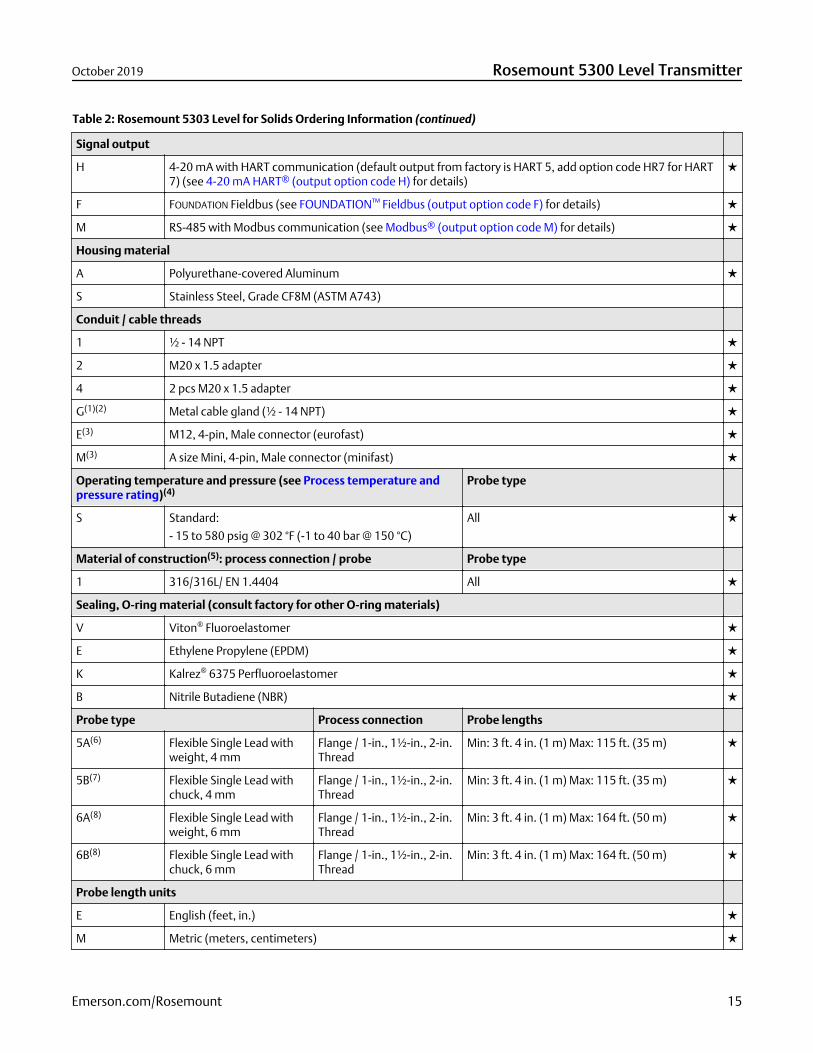
Table 2: Rosemount 5303 Level for Solids Ordering Information (continued)
Signal output
H 4-20 mA with HART communication (default output from factory is HART 5, add option code HR7 for HART7) (see 4-20 mA HART® (output option code H) for details)
F FOUNDATION Fieldbus (see FOUNDATION™ Fieldbus (output option code F) for details)
M RS-485 with Modbus communication (see Modbus® (output option code M) for details)
Housing material
A Polyurethane-covered Aluminum
S Stainless Steel, Grade CF8M (ASTM A743)
Conduit / cable threads
1 ½ - 14 NPT
2 M20 x 1.5 adapter
4 2 pcs M20 x 1.5 adapter
G(1)(2) Metal cable gland (½ - 14 NPT)
E(3) M12, 4-pin, Male connector (eurofast)
M(3) A size Mini, 4-pin, Male connector (minifast)
Operating temperature and pressure (see Process temperature andpressure rating)(4)
Probe type
S Standard:
- 15 to 580 psig @ 302 °F (-1 to 40 bar @ 150 °C)
All
Material of construction(5): process connection / probe Probe type
1 316/316L/ EN 1.4404 All
Sealing, O-ring material (consult factory for other O-ring materials)
V Viton® Fluoroelastomer
E Ethylene Propylene (EPDM)
K Kalrez® 6375 Perfluoroelastomer
B Nitrile Butadiene (NBR)
Probe type Process connection Probe lengths
5A(6) Flexible Single Lead withweight, 4 mm
Flange / 1-in., 1½-in., 2-in.Thread
Min: 3 ft. 4 in. (1 m) Max: 115 ft. (35 m)
5B(7) Flexible Single Lead withchuck, 4 mm
Flange / 1-in., 1½-in., 2-in.Thread
Min: 3 ft. 4 in. (1 m) Max: 115 ft. (35 m)
6A(8) Flexible Single Lead withweight, 6 mm
Flange / 1-in., 1½-in., 2-in.Thread
Min: 3 ft. 4 in. (1 m) Max: 164 ft. (50 m)
6B(8) Flexible Single Lead withchuck, 6 mm
Flange / 1-in., 1½-in., 2-in.Thread
Min: 3 ft. 4 in. (1 m) Max: 164 ft. (50 m)
Probe length units
E English (feet, in.)
M Metric (meters, centimeters)
October 2019 Rosemount 5300 Level Transmitter
Emerson.com/Rosemount 15

Table 2: Rosemount 5303 Level for Solids Ordering Information (continued)
Total probe length (feet/m)(9)
XXX 0-164 ft. or 0-50 m
Total probe length (in./cm)(9)
XX 0-11 in. or 0-99 cm
Process connection - size / type (consult the factory for other process connections)
ASME flanges(10)
AA 2 in. Class 150, RF (Raised Face Type)
AB 2 in. Class 300, RF (Raised Face Type)
BA 3 in. Class 150, RF (Raised Face Type)
BB 3 in. Class 300, RF (Raised Face Type)
CA 4 in. Class 150, RF (Raised Face Type)
CB 4 in. Class 300, RF (Raised Face Type)
DA 6 in. Class 150, RF (Raised Face Type)
EN 1092-1 flanges(11)
HB DN50, PN40, Type A flat face
IA DN80, PN16, Type A flat face
IB DN80, PN40, Type A flat face
JA DN100, PN16, Type A flat face
JB DN100, PN40, Type A flat face
HI DN50, PN40, Type E spigot face
HP DN50, PN16, Type C tongue face
HQ DN50, PN40, Type C tongue face
IH DN80, PN16, Type E spigot face
II DN80, PN40, Type E spigot face
IP DN80, PN16, Type C tongue face
IQ DN80, PN40, Type C tongue face
JH DN100, PN16, Type E spigot face
JI DN100, PN40, Type E spigot face
JP DN100, PN16, Type C tongue face
JQ DN100, PN40, Type C tongue face
KA DN150, PN16, Type A flat face
JIS flanges(11)
UA 50A, 10K, RF (Raised Face Type)
VA 80A, 10K, RF (Raised Face Type)
XA 100A, 10K, RF (Raised Face Type)
UB 50A, 20K, RF (Raised Face Type)
Rosemount 5300 Level Transmitter October 2019
16 Emerson.com/Rosemount
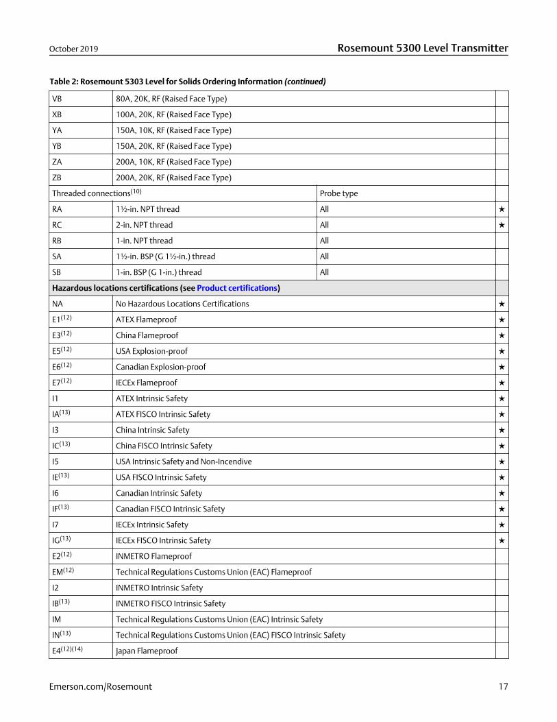
Table 2: Rosemount 5303 Level for Solids Ordering Information (continued)
VB 80A, 20K, RF (Raised Face Type)
XB 100A, 20K, RF (Raised Face Type)
YA 150A, 10K, RF (Raised Face Type)
YB 150A, 20K, RF (Raised Face Type)
ZA 200A, 10K, RF (Raised Face Type)
ZB 200A, 20K, RF (Raised Face Type)
Threaded connections(10) Probe type
RA 1½-in. NPT thread All
RC 2-in. NPT thread All
RB 1-in. NPT thread All
SA 1½-in. BSP (G 1½-in.) thread All
SB 1-in. BSP (G 1-in.) thread All
Hazardous locations certifications (see Product certifications)
NA No Hazardous Locations Certifications
E1(12) ATEX Flameproof
E3(12) China Flameproof
E5(12) USA Explosion-proof
E6(12) Canadian Explosion-proof
E7(12) IECEx Flameproof
I1 ATEX Intrinsic Safety
IA(13) ATEX FISCO Intrinsic Safety
I3 China Intrinsic Safety
IC(13) China FISCO Intrinsic Safety
I5 USA Intrinsic Safety and Non-Incendive
IE(13) USA FISCO Intrinsic Safety
I6 Canadian Intrinsic Safety
IF(13) Canadian FISCO Intrinsic Safety
I7 IECEx Intrinsic Safety
IG(13) IECEx FISCO Intrinsic Safety
E2(12) INMETRO Flameproof
EM(12) Technical Regulations Customs Union (EAC) Flameproof
I2 INMETRO Intrinsic Safety
IB(13) INMETRO FISCO Intrinsic Safety
IM Technical Regulations Customs Union (EAC) Intrinsic Safety
IN(13) Technical Regulations Customs Union (EAC) FISCO Intrinsic Safety
E4(12)(14) Japan Flameproof
October 2019 Rosemount 5300 Level Transmitter
Emerson.com/Rosemount 17
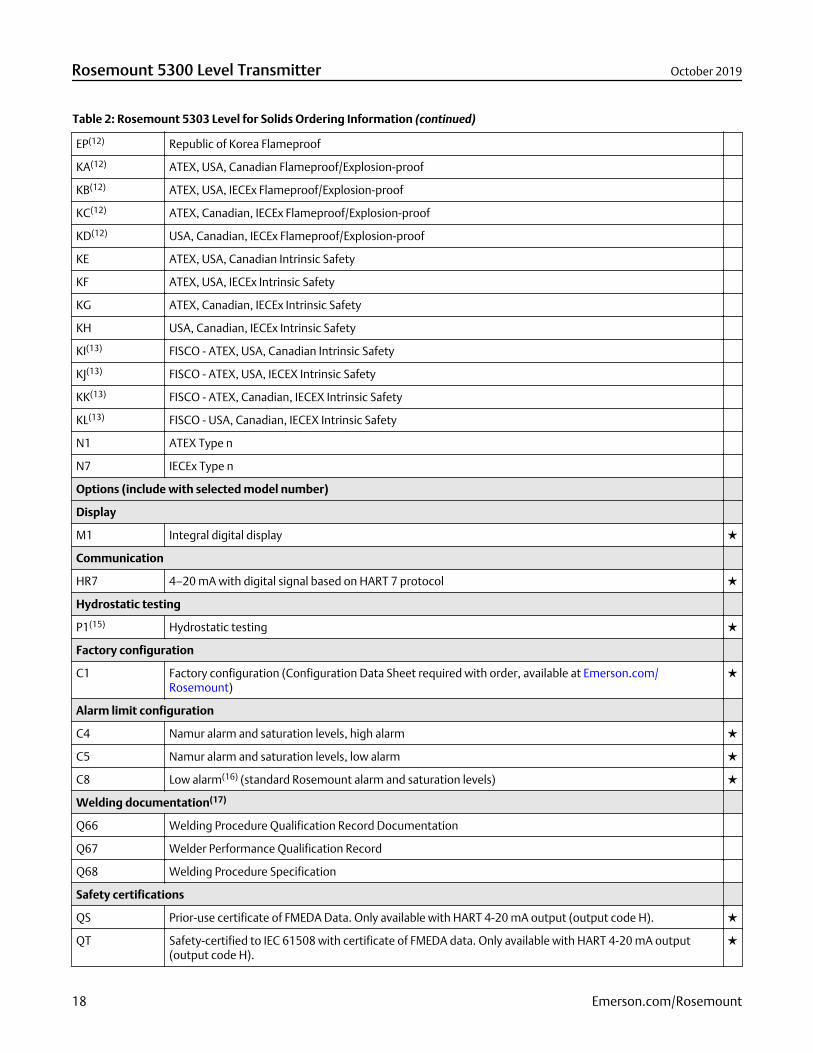
Table 2: Rosemount 5303 Level for Solids Ordering Information (continued)
EP(12) Republic of Korea Flameproof
KA(12) ATEX, USA, Canadian Flameproof/Explosion-proof
KB(12) ATEX, USA, IECEx Flameproof/Explosion-proof
KC(12) ATEX, Canadian, IECEx Flameproof/Explosion-proof
KD(12) USA, Canadian, IECEx Flameproof/Explosion-proof
KE ATEX, USA, Canadian Intrinsic Safety
KF ATEX, USA, IECEx Intrinsic Safety
KG ATEX, Canadian, IECEx Intrinsic Safety
KH USA, Canadian, IECEx Intrinsic Safety
KI(13) FISCO - ATEX, USA, Canadian Intrinsic Safety
KJ(13) FISCO - ATEX, USA, IECEX Intrinsic Safety
KK(13) FISCO - ATEX, Canadian, IECEX Intrinsic Safety
KL(13) FISCO - USA, Canadian, IECEX Intrinsic Safety
N1 ATEX Type n
N7 IECEx Type n
Options (include with selected model number)
Display
M1 Integral digital display
Communication
HR7 4–20 mA with digital signal based on HART 7 protocol
Hydrostatic testing
P1(15) Hydrostatic testing
Factory configuration
C1 Factory configuration (Configuration Data Sheet required with order, available at Emerson.com/Rosemount)
Alarm limit configuration
C4 Namur alarm and saturation levels, high alarm
C5 Namur alarm and saturation levels, low alarm
C8 Low alarm(16) (standard Rosemount alarm and saturation levels)
Welding documentation(17)
Q66 Welding Procedure Qualification Record Documentation
Q67 Welder Performance Qualification Record
Q68 Welding Procedure Specification
Safety certifications
QS Prior-use certificate of FMEDA Data. Only available with HART 4-20 mA output (output code H).
QT Safety-certified to IEC 61508 with certificate of FMEDA data. Only available with HART 4-20 mA output(output code H).
Rosemount 5300 Level Transmitter October 2019
18 Emerson.com/Rosemount
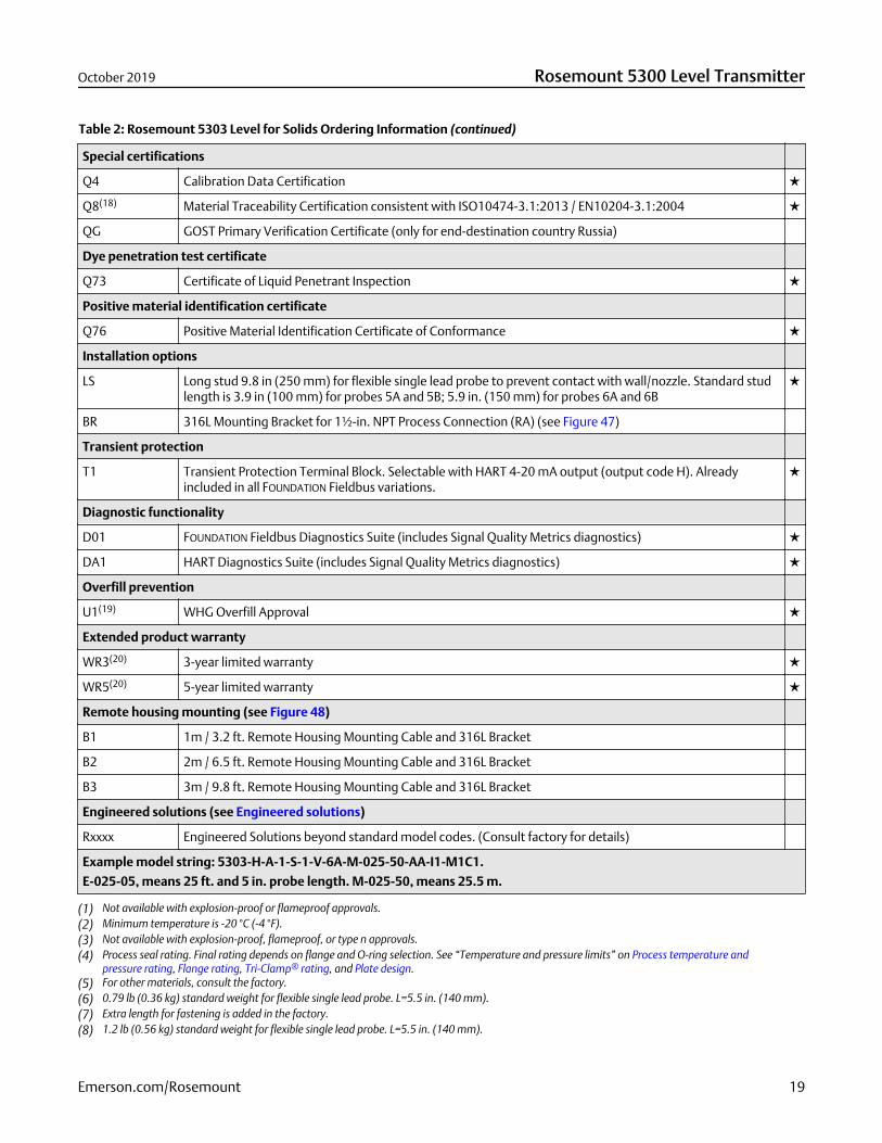
Table 2: Rosemount 5303 Level for Solids Ordering Information (continued)
Special certifications
Q4 Calibration Data Certification
Q8(18) Material Traceability Certification consistent with ISO10474-3.1:2013 / EN10204-3.1:2004
QG GOST Primary Verification Certificate (only for end-destination country Russia)
Dye penetration test certificate
Q73 Certificate of Liquid Penetrant Inspection
Positive material identification certificate
Q76 Positive Material Identification Certificate of Conformance
Installation options
LS Long stud 9.8 in (250 mm) for flexible single lead probe to prevent contact with wall/nozzle. Standard studlength is 3.9 in (100 mm) for probes 5A and 5B; 5.9 in. (150 mm) for probes 6A and 6B
BR 316L Mounting Bracket for 1½-in. NPT Process Connection (RA) (see Figure 47)
Transient protection
T1 Transient Protection Terminal Block. Selectable with HART 4-20 mA output (output code H). Alreadyincluded in all FOUNDATION Fieldbus variations.
Diagnostic functionality
D01 FOUNDATION Fieldbus Diagnostics Suite (includes Signal Quality Metrics diagnostics)
DA1 HART Diagnostics Suite (includes Signal Quality Metrics diagnostics)
Overfill prevention
U1(19) WHG Overfill Approval
Extended product warranty
WR3(20) 3-year limited warranty
WR5(20) 5-year limited warranty
Remote housing mounting (see Figure 48)
B1 1m / 3.2 ft. Remote Housing Mounting Cable and 316L Bracket
B2 2m / 6.5 ft. Remote Housing Mounting Cable and 316L Bracket
B3 3m / 9.8 ft. Remote Housing Mounting Cable and 316L Bracket
Engineered solutions (see Engineered solutions)
Rxxxx Engineered Solutions beyond standard model codes. (Consult factory for details)
Example model string: 5303-H-A-1-S-1-V-6A-M-025-50-AA-I1-M1C1.
E-025-05, means 25 ft. and 5 in. probe length. M-025-50, means 25.5 m.
(1) Not available with explosion-proof or flameproof approvals.(2) Minimum temperature is -20 °C (-4 °F).(3) Not available with explosion-proof, flameproof, or type n approvals.(4) Process seal rating. Final rating depends on flange and O-ring selection. See “Temperature and pressure limits” on Process temperature and
pressure rating, Flange rating, Tri-Clamp® rating, and Plate design.(5) For other materials, consult the factory.(6) 0.79 lb (0.36 kg) standard weight for flexible single lead probe. L=5.5 in. (140 mm).(7) Extra length for fastening is added in the factory.(8) 1.2 lb (0.56 kg) standard weight for flexible single lead probe. L=5.5 in. (140 mm).
October 2019 Rosemount 5300 Level Transmitter
Emerson.com/Rosemount 19
(9) Probe weight included if applicable. Give the total probe length in feet and inches or meters and centimeters, depending on selected probe lengthunit. If tank height is unknown, please round up to an even length when ordering. Probes can be cut to exact length in field. Maximum allowablelength is determined by process conditions. See Total probe length for more probe length guidance.
(10) Available in 316L. For other materials, consult the factory.(11) Available in 316L and EN 1.4404. For other materials consult the factory.(12) Probes are intrinsically safe.(13) Requires FOUNDATION Fieldbus signal output (Ui parameter listed in Product certifications).(14) G ½ in. SST cable gland is included in delivery.(15) Available for tank connection with flange.(16) The standard alarm setting is high.(17) Weldings in accordance with EN/ISO standards.(18) Certificate includes all pressure retaining wetted parts.(19) Cannot be combined with E2 (INMETRO Flameproof) or I2 (INMETRO Intrinsic Safety).(20) Rosemount extended warranties have a limited warranty of three or five years from date of shipment.
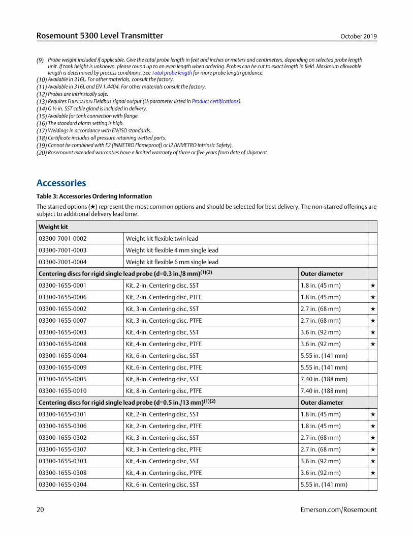
AccessoriesTable 3: Accessories Ordering Information
The starred options () represent the most common options and should be selected for best delivery. The non-starred offerings aresubject to additional delivery lead time.
Weight kit
03300-7001-0002 Weight kit flexible twin lead
03300-7001-0003 Weight kit flexible 4 mm single lead
03300-7001-0004 Weight kit flexible 6 mm single lead
Centering discs for rigid single lead probe (d=0.3 in./8 mm)(1)(2) Outer diameter
03300-1655-0001 Kit, 2-in. Centering disc, SST 1.8 in. (45 mm)
03300-1655-0006 Kit, 2-in. Centering disc, PTFE 1.8 in. (45 mm)
03300-1655-0002 Kit, 3-in. Centering disc, SST 2.7 in. (68 mm)
03300-1655-0007 Kit, 3-in. Centering disc, PTFE 2.7 in. (68 mm)
03300-1655-0003 Kit, 4-in. Centering disc, SST 3.6 in. (92 mm)
03300-1655-0008 Kit, 4-in. Centering disc, PTFE 3.6 in. (92 mm)
03300-1655-0004 Kit, 6-in. Centering disc, SST 5.55 in. (141 mm)
03300-1655-0009 Kit, 6-in. Centering disc, PTFE 5.55 in. (141 mm)
03300-1655-0005 Kit, 8-in. Centering disc, SST 7.40 in. (188 mm)
03300-1655-0010 Kit, 8-in. Centering disc, PTFE 7.40 in. (188 mm)
Centering discs for rigid single lead probe (d=0.5 in./13 mm)(1)(2) Outer diameter
03300-1655-0301 Kit, 2-in. Centering disc, SST 1.8 in. (45 mm)
03300-1655-0306 Kit, 2-in. Centering disc, PTFE 1.8 in. (45 mm)
03300-1655-0302 Kit, 3-in. Centering disc, SST 2.7 in. (68 mm)
03300-1655-0307 Kit, 3-in. Centering disc, PTFE 2.7 in. (68 mm)
03300-1655-0303 Kit, 4-in. Centering disc, SST 3.6 in. (92 mm)
03300-1655-0308 Kit, 4-in. Centering disc, PTFE 3.6 in. (92 mm)
03300-1655-0304 Kit, 6-in. Centering disc, SST 5.55 in. (141 mm)
Rosemount 5300 Level Transmitter October 2019
20 Emerson.com/Rosemount
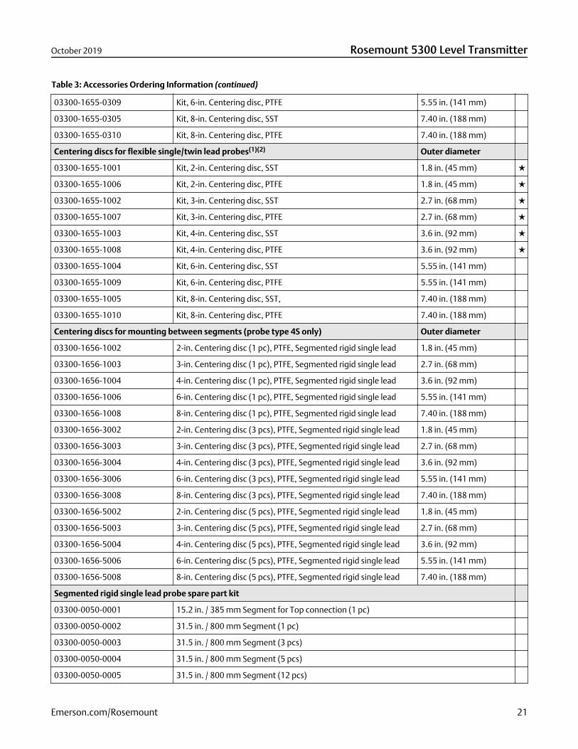
Table 3: Accessories Ordering Information (continued)
03300-1655-0309 Kit, 6-in. Centering disc, PTFE 5.55 in. (141 mm)
03300-1655-0305 Kit, 8-in. Centering disc, SST 7.40 in. (188 mm)
03300-1655-0310 Kit, 8-in. Centering disc, PTFE 7.40 in. (188 mm)
Centering discs for flexible single/twin lead probes(1)(2) Outer diameter
03300-1655-1001 Kit, 2-in. Centering disc, SST 1.8 in. (45 mm)
03300-1655-1006 Kit, 2-in. Centering disc, PTFE 1.8 in. (45 mm)
03300-1655-1002 Kit, 3-in. Centering disc, SST 2.7 in. (68 mm)
03300-1655-1007 Kit, 3-in. Centering disc, PTFE 2.7 in. (68 mm)
03300-1655-1003 Kit, 4-in. Centering disc, SST 3.6 in. (92 mm)
03300-1655-1008 Kit, 4-in. Centering disc, PTFE 3.6 in. (92 mm)
03300-1655-1004 Kit, 6-in. Centering disc, SST 5.55 in. (141 mm)
03300-1655-1009 Kit, 6-in. Centering disc, PTFE 5.55 in. (141 mm)
03300-1655-1005 Kit, 8-in. Centering disc, SST, 7.40 in. (188 mm)
03300-1655-1010 Kit, 8-in. Centering disc, PTFE 7.40 in. (188 mm)
Centering discs for mounting between segments (probe type 4S only) Outer diameter
03300-1656-1002 2-in. Centering disc (1 pc), PTFE, Segmented rigid single lead 1.8 in. (45 mm)
03300-1656-1003 3-in. Centering disc (1 pc), PTFE, Segmented rigid single lead 2.7 in. (68 mm)
03300-1656-1004 4-in. Centering disc (1 pc), PTFE, Segmented rigid single lead 3.6 in. (92 mm)
03300-1656-1006 6-in. Centering disc (1 pc), PTFE, Segmented rigid single lead 5.55 in. (141 mm)
03300-1656-1008 8-in. Centering disc (1 pc), PTFE, Segmented rigid single lead 7.40 in. (188 mm)
03300-1656-3002 2-in. Centering disc (3 pcs), PTFE, Segmented rigid single lead 1.8 in. (45 mm)
03300-1656-3003 3-in. Centering disc (3 pcs), PTFE, Segmented rigid single lead 2.7 in. (68 mm)
03300-1656-3004 4-in. Centering disc (3 pcs), PTFE, Segmented rigid single lead 3.6 in. (92 mm)
03300-1656-3006 6-in. Centering disc (3 pcs), PTFE, Segmented rigid single lead 5.55 in. (141 mm)
03300-1656-3008 8-in. Centering disc (3 pcs), PTFE, Segmented rigid single lead 7.40 in. (188 mm)
03300-1656-5002 2-in. Centering disc (5 pcs), PTFE, Segmented rigid single lead 1.8 in. (45 mm)
03300-1656-5003 3-in. Centering disc (5 pcs), PTFE, Segmented rigid single lead 2.7 in. (68 mm)
03300-1656-5004 4-in. Centering disc (5 pcs), PTFE, Segmented rigid single lead 3.6 in. (92 mm)
03300-1656-5006 6-in. Centering disc (5 pcs), PTFE, Segmented rigid single lead 5.55 in. (141 mm)
03300-1656-5008 8-in. Centering disc (5 pcs), PTFE, Segmented rigid single lead 7.40 in. (188 mm)
Segmented rigid single lead probe spare part kit
03300-0050-0001 15.2 in. / 385 mm Segment for Top connection (1 pc)
03300-0050-0002 31.5 in. / 800 mm Segment (1 pc)
03300-0050-0003 31.5 in. / 800 mm Segment (3 pcs)
03300-0050-0004 31.5 in. / 800 mm Segment (5 pcs)
03300-0050-0005 31.5 in. / 800 mm Segment (12 pcs)
October 2019 Rosemount 5300 Level Transmitter
Emerson.com/Rosemount 21

Table 3: Accessories Ordering Information (continued)
Vented flanges(3)(4)
03300-1812-0092 Fisher™ 249B, 259B
03300-1812-0093 Fisher 249C
03300-1812-0091 Masoneilan™
Flushing connection rings(4)
DP0002-2111-S6 2 in. ANSI, ¼ in. NPT connection
DP0002-3111-S6 3 in. ANSI, ¼ in. NPT connection
DP0002-4111-S6 4 in. ANSI/DN100, ¼ in. NPT connection
DP0002-5111-S6 DN50, ¼ in. NPT connection
DP0002-8111-S6 DN80, ¼ in. NPT connection
HART modem and cables
03300-7004-0001 MACTek® VIATOR® HART Modem and cables (RS232 connection)
03300-7004-0002 MACTek VIATOR HART Modem and cables (USB connection)
Remote housing mounting spare part kit
03300-7006-0001 1 m / 3.2 ft. Remote Housing Mounting Cable and 316L Bracket
03300-7006-0002 2 m / 6.5 ft. Remote Housing Mounting Cable and 316L Bracket
03300-7006-0003 3 m / 9.8 ft. Remote Housing Mounting Cable and 316L Bracket
Verification reflector (high level supervision) spare part kit (requires Rosemount 5300 firmware version 2.H0 or later)
05300-7200-0001 For 3- to 8-in. pipe/chamber (inner diameter)
05300-7200-0002 For tanks or 10-in. pipe/chamber (inner diameter) or wider
(1) If a centering disc is required for a flanged probe, the centering disc can be ordered with options Sx or Px in the model code. If a centering disc isrequired for a threaded connection, or as a spare part, it should be ordered using the item numbers listed in this table. Refer to Table 33 forcentering disc size recommendation for different pipe schedules.
(2) To order a centering disc in a different material consult the factory.(3) 1-½ in. NPT threaded connection (RA) is required.(4) Not available with Country certification option code J1 (CRN).
Rosemount 5300 Level Transmitter October 2019
22 Emerson.com/Rosemount
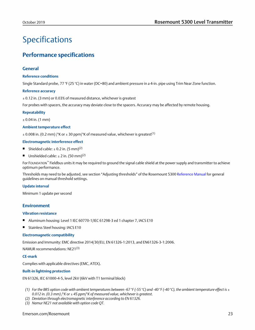
Specifications
Performance specifications
General
Reference conditions
Single Standard probe, 77 °F (25 °C) in water (DC=80) and ambient pressure in a 4-in. pipe using Trim Near Zone function.
Reference accuracy
± 0.12 in. (3 mm) or 0.03% of measured distance, whichever is greatest
For probes with spacers, the accuracy may deviate close to the spacers. Accuracy may be affected by remote housing.
Repeatability
± 0.04 in. (1 mm)
Ambient temperature effect
± 0.008 in. (0.2 mm) /°K or ± 30 ppm/°K of measured value, whichever is greatest(1)
Electromagnetic interference effect
Shielded cable: ± 0.2 in. (5 mm)(2)
Unshielded cable: ± 2 in. (50 mm)(2)
For FOUNDATION™ Fieldbus units it may be required to ground the signal cable shield at the power supply and transmitter to achieveoptimum performance.
Thresholds may need to be adjusted, see section “Adjusting thresholds” of the Rosemount 5300 Reference Manual for generalguidelines on manual threshold settings.
Update interval
Minimum 1 update per second
Environment
Vibration resistance
Aluminum housing: Level 1 IEC 60770-1/IEC 61298-3 ed 1 chapter 7, IACS E10
Stainless Steel housing: IACS E10
Electromagnetic compatibility
Emission and Immunity: EMC directive 2014/30/EU, EN 61326-1:2013, and EN61326-3-1:2006.
NAMUR recommendations: NE21(3)
CE-mark
Complies with applicable directives (EMC, ATEX).
Built-in lightning protection
EN 61326, IEC 61000-4-5, level 2kV (6kV with T1 terminal block)
(1) For the BR5 option code with ambient temperatures between -67 °F (-55 °C) and -40 °F (-40 °C), the ambient temperature effect is ±0.012 in. (0.3 mm) /°K or ± 45 ppm/°K of measured value, whichever is greatest.
(2) Deviation through electromagnetic interference according to EN 61326.(3) Namur NE21 not available with option code QT.
October 2019 Rosemount 5300 Level Transmitter
Emerson.com/Rosemount 23
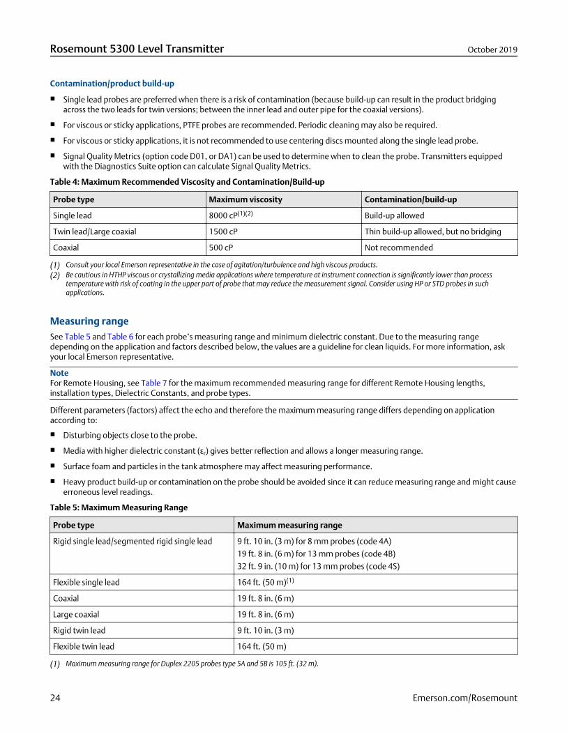
Contamination/product build-up
Single lead probes are preferred when there is a risk of contamination (because build-up can result in the product bridgingacross the two leads for twin versions; between the inner lead and outer pipe for the coaxial versions).
For viscous or sticky applications, PTFE probes are recommended. Periodic cleaning may also be required.
For viscous or sticky applications, it is not recommended to use centering discs mounted along the single lead probe.
Signal Quality Metrics (option code D01, or DA1) can be used to determine when to clean the probe. Transmitters equippedwith the Diagnostics Suite option can calculate Signal Quality Metrics.
Table 4: Maximum Recommended Viscosity and Contamination/Build-up
Probe type Maximum viscosity Contamination/build-up
Single lead 8000 cP(1)(2) Build-up allowed
Twin lead/Large coaxial 1500 cP Thin build-up allowed, but no bridging
Coaxial 500 cP Not recommended
(1) Consult your local Emerson representative in the case of agitation/turbulence and high viscous products.(2) Be cautious in HTHP viscous or crystallizing media applications where temperature at instrument connection is significantly lower than process
temperature with risk of coating in the upper part of probe that may reduce the measurement signal. Consider using HP or STD probes in suchapplications.
Measuring rangeSee Table 5 and Table 6 for each probe’s measuring range and minimum dielectric constant. Due to the measuring rangedepending on the application and factors described below, the values are a guideline for clean liquids. For more information, askyour local Emerson representative.
NoteFor Remote Housing, see Table 7 for the maximum recommended measuring range for different Remote Housing lengths,installation types, Dielectric Constants, and probe types.
Different parameters (factors) affect the echo and therefore the maximum measuring range differs depending on applicationaccording to:
Disturbing objects close to the probe.
Media with higher dielectric constant (εr) gives better reflection and allows a longer measuring range.
Surface foam and particles in the tank atmosphere may affect measuring performance.
Heavy product build-up or contamination on the probe should be avoided since it can reduce measuring range and might causeerroneous level readings.
Table 5: Maximum Measuring Range
Probe type Maximum measuring range
Rigid single lead/segmented rigid single lead 9 ft. 10 in. (3 m) for 8 mm probes (code 4A)
19 ft. 8 in. (6 m) for 13 mm probes (code 4B)
32 ft. 9 in. (10 m) for 13 mm probes (code 4S)
Flexible single lead 164 ft. (50 m)(1)
Coaxial 19 ft. 8 in. (6 m)
Large coaxial 19 ft. 8 in. (6 m)
Rigid twin lead 9 ft. 10 in. (3 m)
Flexible twin lead 164 ft. (50 m)
(1) Maximum measuring range for Duplex 2205 probes type 5A and 5B is 105 ft. (32 m).
Rosemount 5300 Level Transmitter October 2019
24 Emerson.com/Rosemount
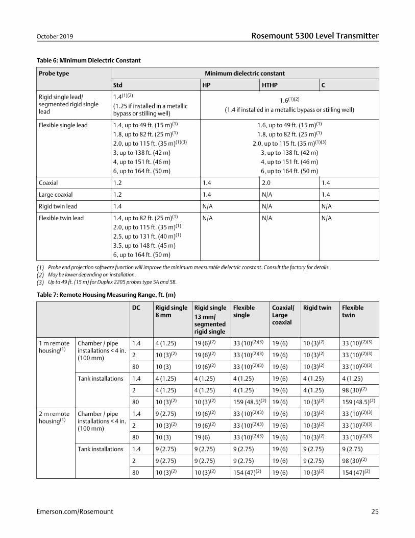
Table 6: Minimum Dielectric Constant
Probe type Minimum dielectric constant
Std HP HTHP C
Rigid single lead/segmented rigid singlelead
1.4(1)(2)
(1.25 if installed in a metallicbypass or stilling well)
1.6(1)(2)
(1.4 if installed in a metallic bypass or stilling well)
Flexible single lead 1.4, up to 49 ft. (15 m)(1)
1.8, up to 82 ft. (25 m)(1)
2.0, up to 115 ft. (35 m)(1)(3)
3, up to 138 ft. (42 m)
4, up to 151 ft. (46 m)
6, up to 164 ft. (50 m)
1.6, up to 49 ft. (15 m)(1)
1.8, up to 82 ft. (25 m)(1)
2.0, up to 115 ft. (35 m)(1)(3)
3, up to 138 ft. (42 m)
4, up to 151 ft. (46 m)
6, up to 164 ft. (50 m)
Coaxial 1.2 1.4 2.0 1.4
Large coaxial 1.2 1.4 N/A 1.4
Rigid twin lead 1.4 N/A N/A N/A
Flexible twin lead 1.4, up to 82 ft. (25 m)(1)
2.0, up to 115 ft. (35 m)(1)
2.5, up to 131 ft. (40 m)(1)
3.5, up to 148 ft. (45 m)
6, up to 164 ft. (50 m)
N/A N/A N/A
(1) Probe end projection software function will improve the minimum measurable dielectric constant. Consult the factory for details.(2) May be lower depending on installation.(3) Up to 49 ft. (15 m) for Duplex 2205 probes type 5A and 5B.
Table 7: Remote Housing Measuring Range, ft. (m)
DC Rigid single8 mm
Rigid single
13 mm/segmentedrigid single
Flexiblesingle
Coaxial/Largecoaxial
Rigid twin Flexibletwin
1 m remotehousing(1)
Chamber / pipeinstallations < 4 in.(100 mm)
1.4 4 (1.25) 19 (6)(2) 33 (10)(2)(3) 19 (6) 10 (3)(2) 33 (10)(2)(3)
2 10 (3)(2) 19 (6)(2) 33 (10)(2)(3) 19 (6) 10 (3)(2) 33 (10)(2)(3)
80 10 (3) 19 (6)(2) 33 (10)(2)(3) 19 (6) 10 (3)(2) 33 (10)(2)(3)
Tank installations 1.4 4 (1.25) 4 (1.25) 4 (1.25) 19 (6) 4 (1.25) 4 (1.25)
2 4 (1.25) 4 (1.25) 4 (1.25) 19 (6) 4 (1.25) 98 (30)(2)
80 10 (3)(2) 10 (3)(2) 159 (48.5)(2) 19 (6) 10 (3)(2) 159 (48.5)(2)
2 m remotehousing(1)
Chamber / pipeinstallations < 4 in.(100 mm)
1.4 9 (2.75) 19 (6)(2) 33 (10)(2)(3) 19 (6) 10 (3)(2) 33 (10)(2)(3)
2 10 (3)(2) 19 (6)(2) 33 (10)(2)(3) 19 (6) 10 (3)(2) 33 (10)(2)(3)
80 10 (3) 19 (6) 33 (10)(2)(3) 19 (6) 10 (3)(2) 33 (10)(2)(3)
Tank installations 1.4 9 (2.75) 9 (2.75) 9 (2.75) 19 (6) 9 (2.75) 9 (2.75)
2 9 (2.75) 9 (2.75) 9 (2.75) 19 (6) 9 (2.75) 98 (30)(2)
80 10 (3)(2) 10 (3)(2) 154 (47)(2) 19 (6) 10 (3)(2) 154 (47)(2)
October 2019 Rosemount 5300 Level Transmitter
Emerson.com/Rosemount 25
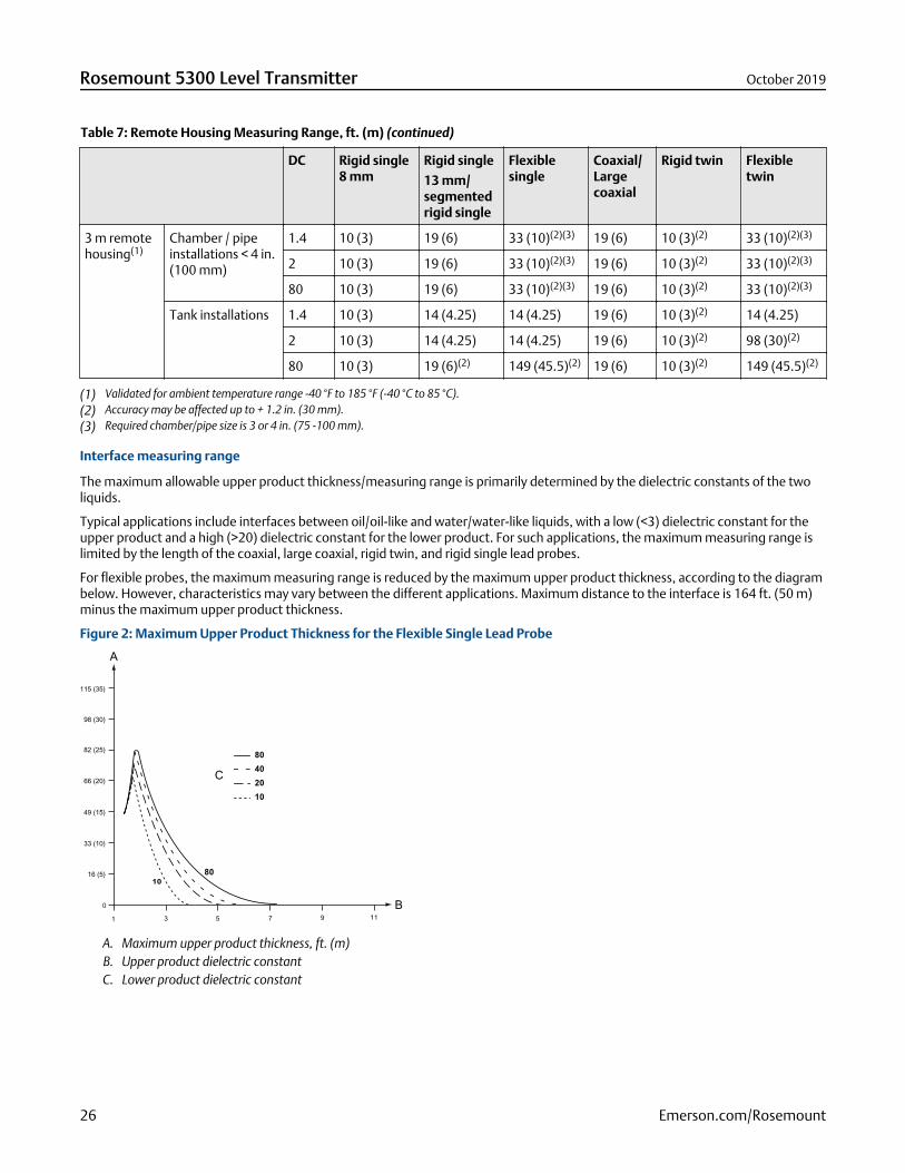
Table 7: Remote Housing Measuring Range, ft. (m) (continued)
DC Rigid single8 mm
Rigid single
13 mm/segmentedrigid single
Flexiblesingle
Coaxial/Largecoaxial
Rigid twin Flexibletwin
3 m remotehousing(1)
Chamber / pipeinstallations < 4 in.(100 mm)
1.4 10 (3) 19 (6) 33 (10)(2)(3) 19 (6) 10 (3)(2) 33 (10)(2)(3)
2 10 (3) 19 (6) 33 (10)(2)(3) 19 (6) 10 (3)(2) 33 (10)(2)(3)
80 10 (3) 19 (6) 33 (10)(2)(3) 19 (6) 10 (3)(2) 33 (10)(2)(3)
Tank installations 1.4 10 (3) 14 (4.25) 14 (4.25) 19 (6) 10 (3)(2) 14 (4.25)
2 10 (3) 14 (4.25) 14 (4.25) 19 (6) 10 (3)(2) 98 (30)(2)
80 10 (3) 19 (6)(2) 149 (45.5)(2) 19 (6) 10 (3)(2) 149 (45.5)(2)
(1) Validated for ambient temperature range -40 °F to 185 °F (-40 °C to 85 °C).(2) Accuracy may be affected up to + 1.2 in. (30 mm).(3) Required chamber/pipe size is 3 or 4 in. (75 -100 mm).
Interface measuring range
The maximum allowable upper product thickness/measuring range is primarily determined by the dielectric constants of the twoliquids.
Typical applications include interfaces between oil/oil-like and water/water-like liquids, with a low (<3) dielectric constant for theupper product and a high (>20) dielectric constant for the lower product. For such applications, the maximum measuring range islimited by the length of the coaxial, large coaxial, rigid twin, and rigid single lead probes.
For flexible probes, the maximum measuring range is reduced by the maximum upper product thickness, according to the diagrambelow. However, characteristics may vary between the different applications. Maximum distance to the interface is 164 ft. (50 m)minus the maximum upper product thickness.
Figure 2: Maximum Upper Product Thickness for the Flexible Single Lead Probe
1 3 5 7 9 110
16 (5)
33 (10)
49 (15)
66 (20)
82 (25)
98 (30)
115 (35)
A
B
C
A. Maximum upper product thickness, ft. (m)B. Upper product dielectric constantC. Lower product dielectric constant
Rosemount 5300 Level Transmitter October 2019
26 Emerson.com/Rosemount
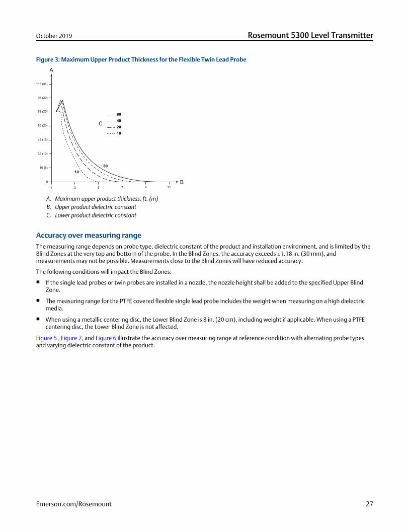
Figure 3: Maximum Upper Product Thickness for the Flexible Twin Lead Probe
1 3 5 7 9 110
16 (5)
33 (10)
49 (15)
66 (20)
82 (25)
98 (30)
115 (35)
A
B
C
A. Maximum upper product thickness, ft. (m)B. Upper product dielectric constantC. Lower product dielectric constant
Accuracy over measuring rangeThe measuring range depends on probe type, dielectric constant of the product and installation environment, and is limited by theBlind Zones at the very top and bottom of the probe. In the Blind Zones, the accuracy exceeds ±1.18 in. (30 mm), andmeasurements may not be possible. Measurements close to the Blind Zones will have reduced accuracy.
The following conditions will impact the Blind Zones:
If the single lead probes or twin probes are installed in a nozzle, the nozzle height shall be added to the specified Upper BlindZone.
The measuring range for the PTFE covered flexible single lead probe includes the weight when measuring on a high dielectricmedia.
When using a metallic centering disc, the Lower Blind Zone is 8 in. (20 cm), including weight if applicable. When using a PTFEcentering disc, the Lower Blind Zone is not affected.
Figure 5 , Figure 7, and Figure 6 illustrate the accuracy over measuring range at reference condition with alternating probe typesand varying dielectric constant of the product.
October 2019 Rosemount 5300 Level Transmitter
Emerson.com/Rosemount 27
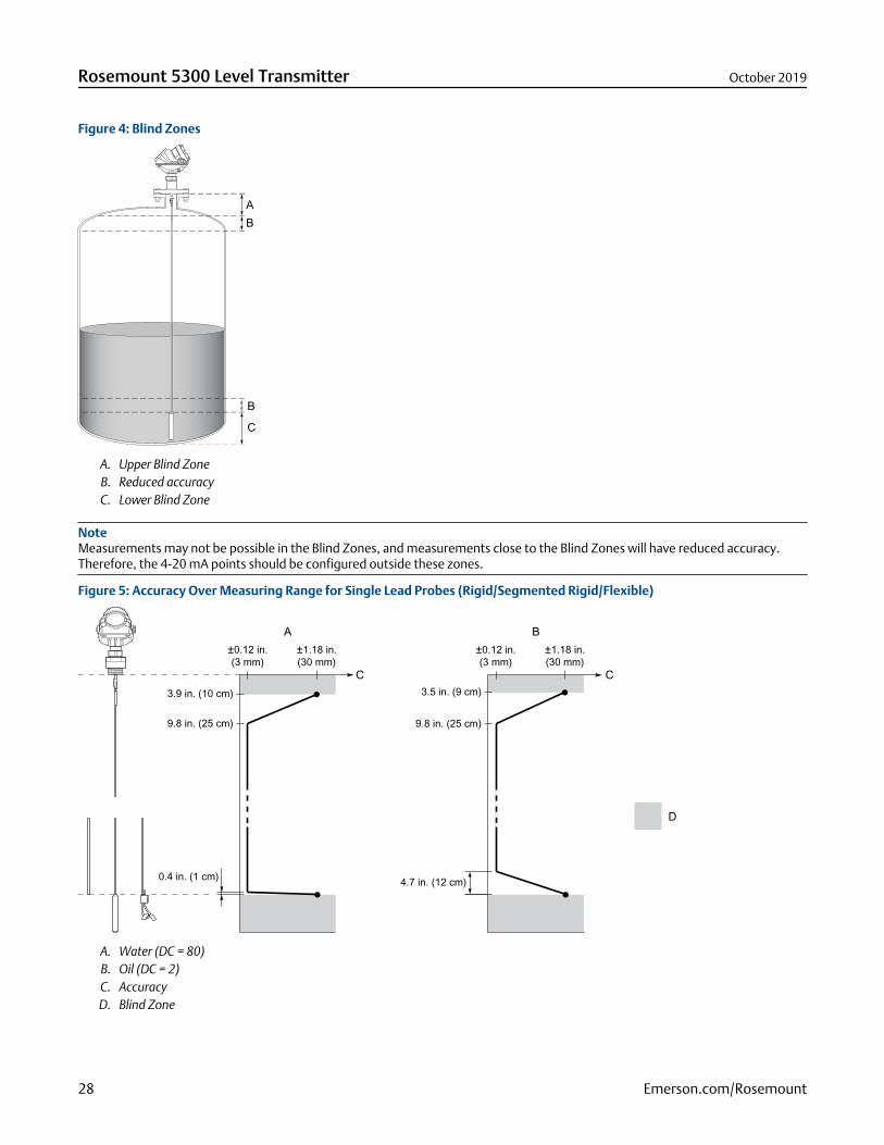
Figure 4: Blind Zones
A. Upper Blind ZoneB. Reduced accuracyC. Lower Blind Zone
NoteMeasurements may not be possible in the Blind Zones, and measurements close to the Blind Zones will have reduced accuracy.Therefore, the 4-20 mA points should be configured outside these zones.
Figure 5: Accuracy Over Measuring Range for Single Lead Probes (Rigid/Segmented Rigid/Flexible)
C
A B
D
C
±0.12 in.(3 mm)
3.5 in. (9 cm)
9.8 in. (25 cm)
4.7 in. (12 cm)
±1.18 in.(30 mm)
±0.12 in.(3 mm)
3.9 in. (10 cm)
9.8 in. (25 cm)
0.4 in. (1 cm)
±1.18 in.(30 mm)
A. Water (DC = 80)B. Oil (DC = 2)C. AccuracyD. Blind Zone
Rosemount 5300 Level Transmitter October 2019
28 Emerson.com/Rosemount
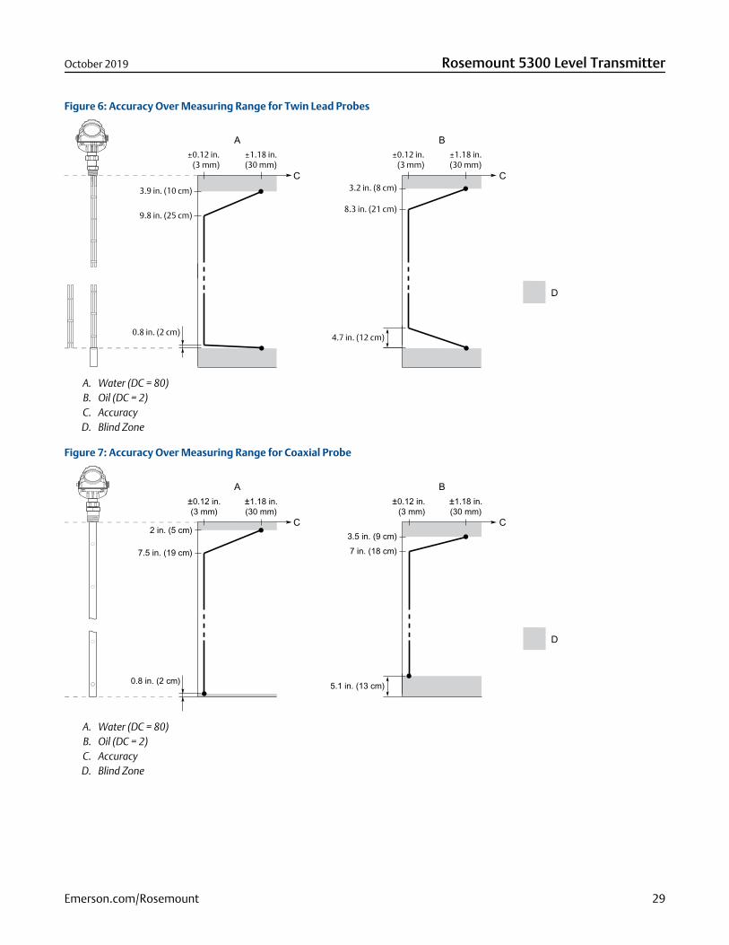
Figure 6: Accuracy Over Measuring Range for Twin Lead Probes
±0.12 in.(3 mm)
3.2 in. (8 cm)
8.3 in. (21 cm)
4.7 in. (12 cm)
±1.18 in.(30 mm)
±0.12 in.(3 mm)
3.9 in. (10 cm)
9.8 in. (25 cm)
0.8 in. (2 cm)
±1.18 in.(30 mm)
C
A B
D
C
A. Water (DC = 80)B. Oil (DC = 2)C. AccuracyD. Blind Zone
Figure 7: Accuracy Over Measuring Range for Coaxial Probe
±0.12 in.(3 mm)
3.5 in. (9 cm)7 in. (18 cm)
5.1 in. (13 cm)
±1.18 in.(30 mm)
±0.12 in.(3 mm)
2 in. (5 cm)
7.5 in. (19 cm)
0.8 in. (2 cm)
±1.18 in.(30 mm)
C
A B
D
C
A. Water (DC = 80)B. Oil (DC = 2)C. AccuracyD. Blind Zone
October 2019 Rosemount 5300 Level Transmitter
Emerson.com/Rosemount 29
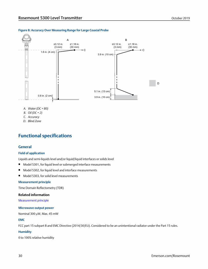
Figure 8: Accuracy Over Measuring Range for Large Coaxial Probe
±0.12 in.(3 mm)
3.9 in. (10 cm)
±1.18 in.(30 mm)
±0.12 in.(3 mm)
1.6 in. (4 cm)
±1.18 in.(30 mm)
0.8 in. (2 cm)
5.1 in. (13 cm)
3.9 in. (10 cm)
C
A B
D
C
A. Water (DC = 80)B. Oil (DC = 2)C. AccuracyD. Blind Zone
Functional specifications
General
Field of application
Liquids and semi-liquids level and/or liquid/liquid interfaces or solids level
Model 5301, for liquid level or submerged interface measurements
Model 5302, for liquid level and interface measurements
Model 5303, for solid level measurements
Measurement principle
Time Domain Reflectometry (TDR)
Related information
Measurement principle
Microwave output power
Nominal 300 µW, Max. 45 mW
EMC
FCC part 15 subpart B and EMC Directive (2014/30/EU). Considered to be an unintentional radiator under the Part 15 rules.
Humidity
0 to 100% relative humidity
Rosemount 5300 Level Transmitter October 2019
30 Emerson.com/Rosemount

Start-up time
< 40 s(4)
(4) The start-up time is extended with five additional minutes for option code BR5 at temperatures below -40 °F (-40 °C). Refer to Figure10.
October 2019 Rosemount 5300 Level Transmitter
Emerson.com/Rosemount 31
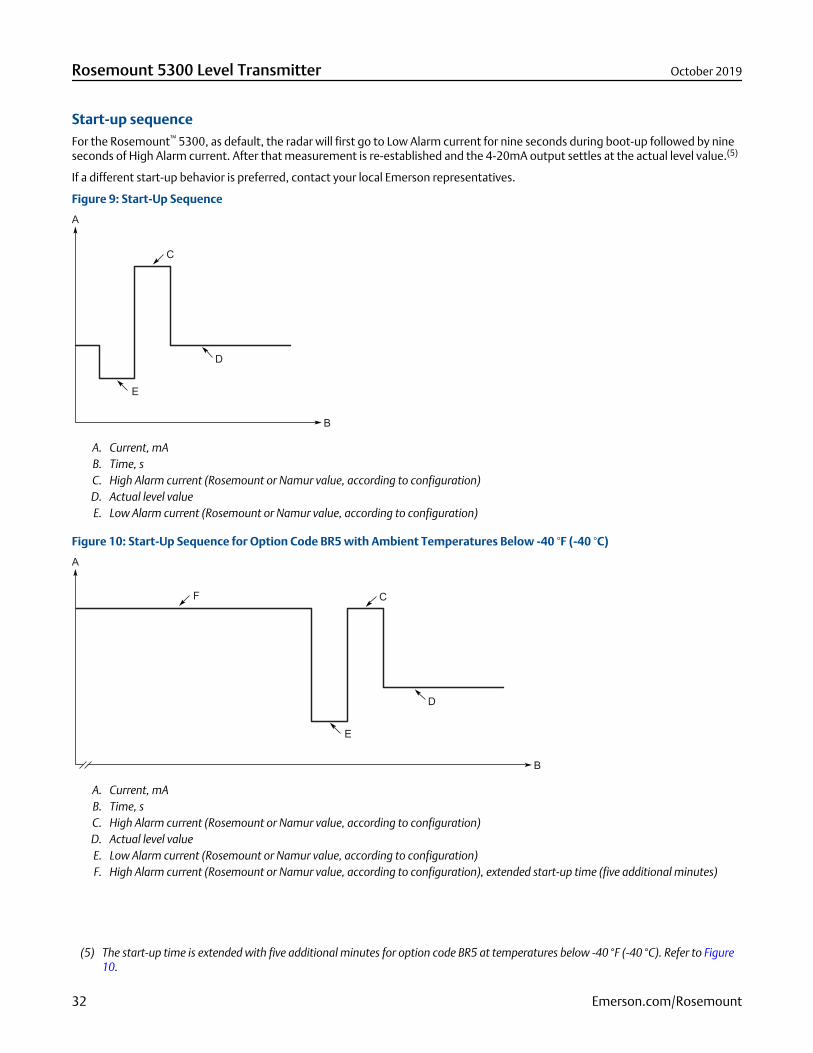
Start-up sequenceFor the Rosemount™ 5300, as default, the radar will first go to Low Alarm current for nine seconds during boot-up followed by nineseconds of High Alarm current. After that measurement is re-established and the 4-20mA output settles at the actual level value.(5)
If a different start-up behavior is preferred, contact your local Emerson representatives.
Figure 9: Start-Up Sequence
A. Current, mAB. Time, sC. High Alarm current (Rosemount or Namur value, according to configuration)D. Actual level valueE. Low Alarm current (Rosemount or Namur value, according to configuration)
Figure 10: Start-Up Sequence for Option Code BR5 with Ambient Temperatures Below -40 °F (-40 °C)
A. Current, mAB. Time, sC. High Alarm current (Rosemount or Namur value, according to configuration)D. Actual level valueE. Low Alarm current (Rosemount or Namur value, according to configuration)F. High Alarm current (Rosemount or Namur value, according to configuration), extended start-up time (five additional minutes)
(5) The start-up time is extended with five additional minutes for option code BR5 at temperatures below -40 °F (-40 °C). Refer to Figure10.
Rosemount 5300 Level Transmitter October 2019
32 Emerson.com/Rosemount

4-20 mA HART® (output option code H)
Output
Two-wire, 4-20 mA. Digital process variable is superimposed on 4-20 mA signal, and available to any host that conforms to theHART protocol. The digital HART® signal can be used in multidrop mode.
The default output is HART Revision 5. To order HART Revision 7 factory configured, add option code HR7. The device can also befield configured to HART Revision 7 if needed.
Signal wiring
Recommended output cabling is twisted shielded pairs, 24-12 AWG.
Rosemount 333 HART® Tri-Loop™
By sending the digital HART signal to the optional HART Tri-Loop, it is possible to have up to three additional 4–20 mA analogsignals.
See the Rosemount 333 HART Tri-Loop Product Data Sheet for additional information.
Emerson Wireless 775 THUM™ Adapter
The optional Emerson Wireless 775 THUM Adapter can be mounted directly on the transmitter or by using a remote mounting kit.
IEC 62591 (WirelessHART®) enables access to multivariable data and diagnostics, and adds wireless to almost any measurementpoint.
See the Emerson Wireless 775 THUM Adapter Product Data Sheet and Technical Note for additional information.
Power requirements
Terminals in the transmitter housing provide connections for signal cables. The Rosemount 5300 Level Transmitter is loop-poweredand operates with the following power supplies:
Table 8: External Power Supply for HART
Approval type Input voltage (Ui)(1)
None 16 - 42.4 Vdc
Non-sparking/Energy Limited 16 - 42.4 Vdc
Intrinsically Safe 16 - 30 Vdc
Explosion-proof/Flameproof 20 - 42.4 Vdc
(1) Reverse polarity protection.
October 2019 Rosemount 5300 Level Transmitter
Emerson.com/Rosemount 33
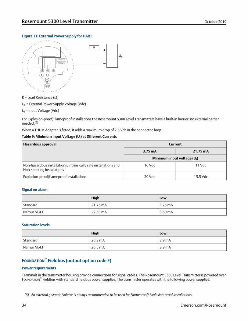
Figure 11: External Power Supply for HART
R = Load Resistance (Ω)
UE = External Power Supply Voltage (Vdc)
Ui = Input Voltage (Vdc)
For Explosion-proof/Flameproof installations the Rosemount 5300 Level Transmitters have a built-in barrier; no external barrierneeded.(6)
When a THUM Adapter is fitted, it adds a maximum drop of 2.5 Vdc in the connected loop.
Table 9: Minimum Input Voltage (Ui) at Different Currents
Hazardous approval Current
3.75 mA 21.75 mA
Minimum input voltage (Ui)
Non-hazardous installations, intrinsically safe installations andNon-sparking installations
16 Vdc 11 Vdc
Explosion-proof/flameproof installations 20 Vdc 15.5 Vdc
Signal on alarm
High Low
Standard 21.75 mA 3.75 mA
Namur NE43 22.50 mA 3.60 mA
Saturation levels
High Low
Standard 20.8 mA 3.9 mA
Namur NE43 20.5 mA 3.8 mA
FOUNDATION™ Fieldbus (output option code F)
Power requirements
Terminals in the transmitter housing provide connections for signal cables. The Rosemount 5300 Level Transmitter is powered overFOUNDATION™ Fieldbus with standard fieldbus power supplies. The transmitter operates with the following power supplies:
(6) An external galvanic isolator is always recommended to be used for Flameproof/ Explosion-proof installations.
Rosemount 5300 Level Transmitter October 2019
34 Emerson.com/Rosemount
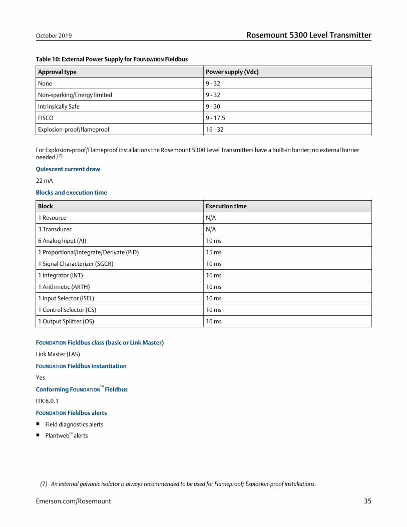
Table 10: External Power Supply for FOUNDATION Fieldbus
Approval type Power supply (Vdc)
None 9 - 32
Non-sparking/Energy limited 9 - 32
Intrinsically Safe 9 - 30
FISCO 9 - 17.5
Explosion-proof/flameproof 16 - 32
For Explosion-proof/Flameproof installations the Rosemount 5300 Level Transmitters have a built-in barrier; no external barrierneeded.(7)
Quiescent current draw
22 mA
Blocks and execution time
Block Execution time
1 Resource N/A
3 Transducer N/A
6 Analog Input (AI) 10 ms
1 Proportional/Integrate/Derivate (PID) 15 ms
1 Signal Characterizer (SGCR) 10 ms
1 Integrator (INT) 10 ms
1 Arithmetic (ARTH) 10 ms
1 Input Selector (ISEL) 10 ms
1 Control Selector (CS) 10 ms
1 Output Splitter (OS) 10 ms
FOUNDATION Fieldbus class (basic or Link Master)
Link Master (LAS)
FOUNDATION Fieldbus instantiation
Yes
Conforming FOUNDATION™ Fieldbus
ITK 6.0.1
FOUNDATION Fieldbus alerts
Field diagnostics alerts
Plantweb™ alerts
(7) An external galvanic isolator is always recommended to be used for Flameproof/ Explosion-proof installations.
October 2019 Rosemount 5300 Level Transmitter
Emerson.com/Rosemount 35
Modbus® (output option code M)
Output
The RS-485 Modbus version communicates by Modbus RTU, Modbus ASCII, and Levelmaster protocols.
8 data bits, 1 start bit, 1 stop bit, and software selectable parity.
Baud Rate 1200, 2400, 4800, 9600 (default), and 19200 bits/s
Address Range 1 to 255 (default device address is 246)
HART communication is used for configuration via the HART terminals or tunneling via the RS-485.
External power supply
The input voltage Ui for Modbus is 8-30 Vdc (max. rating).
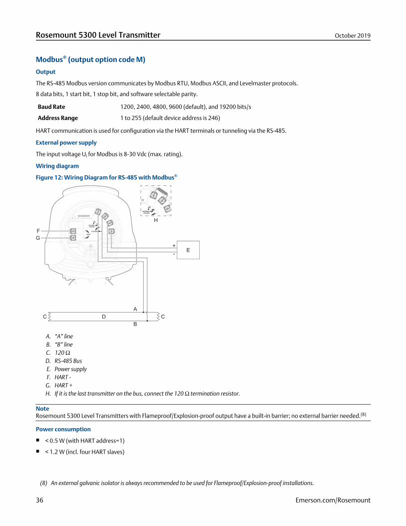
Wiring diagram
Figure 12: Wiring Diagram for RS-485 with Modbus®
-
+
A. “A” lineB. “B” lineC. 120 ΩD. RS-485 BusE. Power supplyF. HART -
G. HART +H. If it is the last transmitter on the bus, connect the 120 Ω termination resistor.
NoteRosemount 5300 Level Transmitters with Flameproof/Explosion-proof output have a built-in barrier; no external barrier needed.(8)
Power consumption
< 0.5 W (with HART address=1)
< 1.2 W (incl. four HART slaves)
(8) An external galvanic isolator is always recommended to be used for Flameproof/Explosion-proof installations.
Rosemount 5300 Level Transmitter October 2019
36 Emerson.com/Rosemount
NoteThe Rosemount 5300 Level Transmitter with Modbus protocol is configured to HART address 1 at factory. This reduces powerconsumption by locking the analog output at 4 mA.
Display and configuration
Integral display (option code M1)
The integral digital display can toggle between: level, distance, volume, internal temperature, interface distance, interface level,peak amplitudes, interface thickness, percentage of range, analog current out.
NoteThe display cannot be used for configuration purposes.
Remote display
Data can be read remotely using the Rosemount 751 Field Signal Indicator for 4-20 mA / HART® (see Product Data Sheet), or theRosemount 752 Remote Indicator for FOUNDATION™ Fieldbus (see Product Data Sheet).
Configuration tools
Rosemount Radar Master (included in the delivery)
Device Descriptor (DD) based systems, e.g. AMS Device Manager, handheld communicator, and DeltaV™
Device Type Manager (DTM™) based systems (compliant with version 1.2 of the FDT®/DTM specification), supportingconfiguration in for instance Yokogawa Fieldmate/PRM, E+H FieldCare®, and PACTware™
Output units
Level, Interface and Distance: ft., in., m, cm, or mm
Level Rate: ft./s, m/s, in./min, m/h
Volume: ft.3, in.3, US gals, Imp gals, barrels, yd3, m3, or liters
Temperature: °F and °C
October 2019 Rosemount 5300 Level Transmitter
Emerson.com/Rosemount 37
Output variables
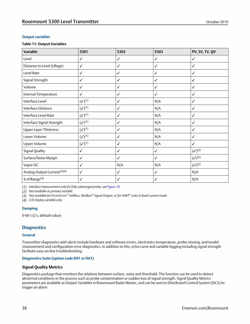
Table 11: Output Variables
Variable 5301 5302 5303 PV, SV, TV, QV
Level
Distance to Level (Ullage)
Level Rate
Signal Strength
Volume
Internal Temperature
Interface Level ()(1) N/A
Interface Distance ()(1) N/A
Interface Level Rate ()(1) N/A
Interface Signal Strength ()(1) N/A
Upper Layer Thickness ()(1) N/A
Lower Volume ()(1) N/A
Upper Volume ()(1) N/A
Signal Quality ()(2)
Surface/Noise Margin ()(2)
Vapor DC N/A N/A ()(2)
Analog Output Current(3)(4) N/A
% of Range(4) N/A
(1) Interface measurement only for fully submerged probe, see Figure 18.(2) Not available as primary variable.(3) Not available for FOUNDATION™ Fieldbus, Modbus® Signal Output, or for HART® units in fixed current mode.(4) LCD display variable only.
Damping
0-60 s (2 s, default value)
Diagnostics
General
Transmitter diagnostics with alerts include hardware and software errors, electronics temperature, probe missing, and invalidmeasurement and configuration error diagnostics. In addition to this, echo curve and variable logging including signal strengthfacilitate easy on-line troubleshooting.
Diagnostics Suite (option code D01 or DA1)
Signal Quality Metrics
Diagnostics package that monitors the relations between surface, noise and threshold. The function can be used to detectabnormal conditions in the process such as probe contamination or sudden loss of signal strength. Signal Quality Metricsparameters are available as Output Variables in Rosemount Radar Master, and can be sent to Distributed Control System (DCS) totrigger an alarm.
Rosemount 5300 Level Transmitter October 2019
38 Emerson.com/Rosemount
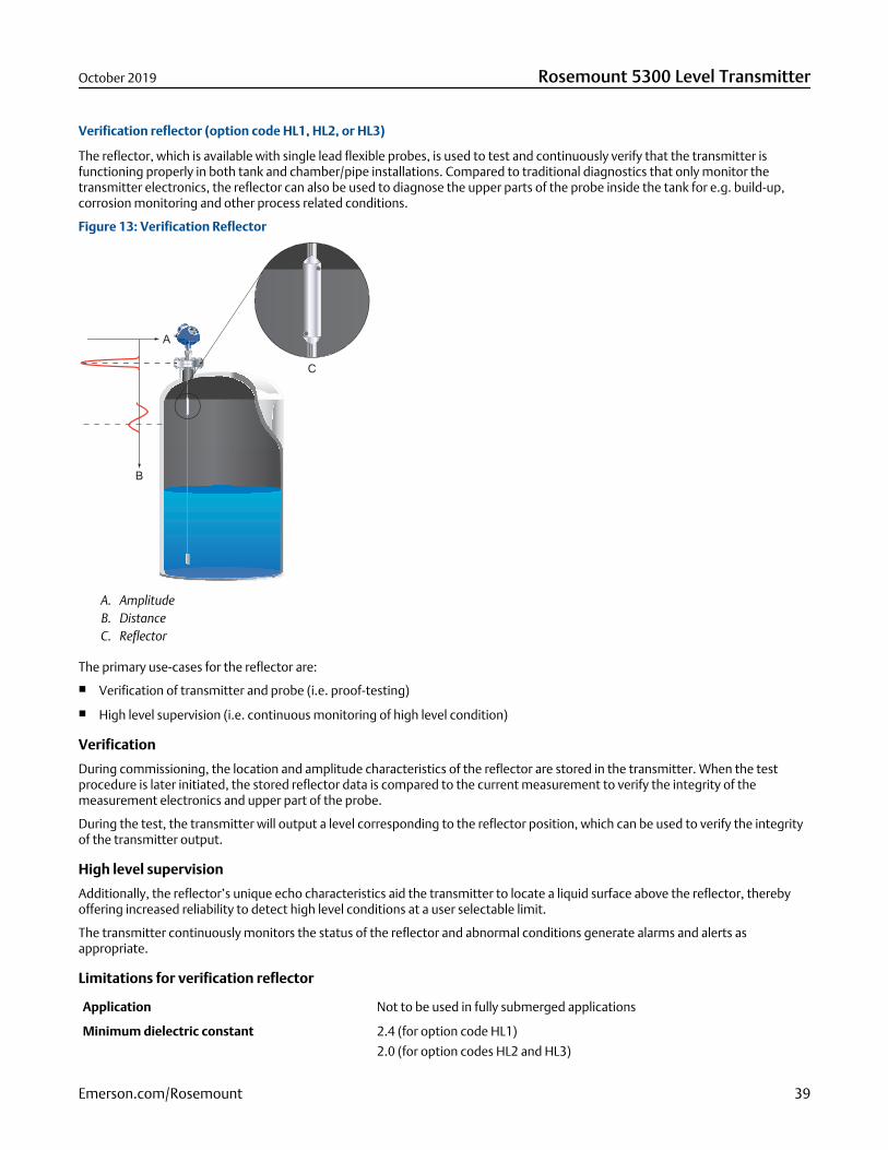
Verification reflector (option code HL1, HL2, or HL3)
The reflector, which is available with single lead flexible probes, is used to test and continuously verify that the transmitter isfunctioning properly in both tank and chamber/pipe installations. Compared to traditional diagnostics that only monitor thetransmitter electronics, the reflector can also be used to diagnose the upper parts of the probe inside the tank for e.g. build-up,corrosion monitoring and other process related conditions.
Figure 13: Verification Reflector
A. AmplitudeB. DistanceC. Reflector
The primary use-cases for the reflector are:
Verification of transmitter and probe (i.e. proof-testing)
High level supervision (i.e. continuous monitoring of high level condition)
Verification
During commissioning, the location and amplitude characteristics of the reflector are stored in the transmitter. When the testprocedure is later initiated, the stored reflector data is compared to the current measurement to verify the integrity of themeasurement electronics and upper part of the probe.
During the test, the transmitter will output a level corresponding to the reflector position, which can be used to verify the integrityof the transmitter output.
High level supervision
Additionally, the reflector’s unique echo characteristics aid the transmitter to locate a liquid surface above the reflector, therebyoffering increased reliability to detect high level conditions at a user selectable limit.
The transmitter continuously monitors the status of the reflector and abnormal conditions generate alarms and alerts asappropriate.
Limitations for verification reflector
Application Not to be used in fully submerged applications
Minimum dielectric constant 2.4 (for option code HL1)
2.0 (for option codes HL2 and HL3)
October 2019 Rosemount 5300 Level Transmitter
Emerson.com/Rosemount 39

More information
For more information and installation requirements, refer to the High Level Supervision Manual Supplement.
Process temperature and pressure ratingFigure 14 gives the maximum process temperature (measured at the lower part of the flange or threaded connection) and pressurerating for tank connections:
Standard (model code S)
HTHP - High Temperature and High Pressure (model code H)
HP - High Pressure (model code P)
C - Cryogenic temperature (model code C)
For standard tank connection, final rating may be lower depending on flange, material of construction, and O-ring selection. Table12 gives the temperature ranges for standard tank seals with different O-ring materials.
Table 12: Temperature Ranges for Standard Tank Seals with Different O-ring Material
O-ring material Temperature °F (°C) in air
Minimum (1) Maximum
Viton® Fluoroelastomer 5 (-15) 302 (150)
Ethylene Propylene (EPDM) -40 (-40) 266 (130)
Kalrez® 6375 Perfluoroelastomer 14 (-10) 302 (150)
Nitrile Butadiene (NBR) -31 (-35) 230 (110)
Low Temperature Viton Fluoroelastomer -22 (-30) 302 (150)
Fluorosilicone (FVMQ) -49 (-45) 302 (150)
(1) The O-ring can be stored at lower temperatures (refer to Table 13).
NoteAlways check the chemical compatibility of the O-ring material with your application. If the O-ring material is not compatible withits chemical environment, the O-ring may eventually malfunction.
No wetted O-rings are used in the HTHP, HP, and C versions. Final rating may be lower depending on flange and material ofconstruction selection.
Rosemount 5300 Level Transmitter October 2019
40 Emerson.com/Rosemount

Figure 14: Process Temperature and Pressure - Max Rating
580 (40)
232 (16)
-14 (-1)-40 *
(-40)302
(150)
5000 (345)
1000 (69)
752(400)
2940 (203)
-14 (-1)100(38)
-76(-60)
0 400(204)
600(316)
200(93)
5000 (345)
3320 (228.9)3000 (206)
1000 (69)
-14 (-1)-76
(-60)100(38)
200(93)
400(204)
-320 (-196)
-200 (-129)
0 100(38)
200(93)
392(200)
3524 (243)
5000 (345)
3000 (206)
1000 (69)
-14 (-1)482
(250)0
AE
G
F
F F
F
E
E EC D
B
A. Standard tank connectionsB. HTHP tank connectionsC. HP tank connectionsD. C tank connectionsE. Pressure psig (bar)F. Temperature °F (°C)
G. PTFE covered probe and flange
* -49 °F (-45 °C) depending on O-ring selection
Temperature limitsThe maximum and minimum ambient temperature for the electronics depends on the process temperature (as described by Figure15 and Figure 16) and on the approval (see Product certifications).
Figure 15: Ambient Temperature vs. Process Temperature
A
B
185 (85)
131 (55)
100 (38)
50 (10)
-40 (-40) 392 (200)
-17 (-27)
-40 (-40)
200 (93) 400 (204) 600 (316) 800(427)
-320(-196)
752 (400)
A. Ambient temperature °F (°C)B. Process temperature °F (°C)
October 2019 Rosemount 5300 Level Transmitter
Emerson.com/Rosemount 41

Figure 16: Ambient Temperature vs. Process Temperature with Option Code BR5
A
B
185 (85)
131 (55)
100 (38)
50 (10)
-67 (-55) 392 (200)
-17 (-27)
-67 (-55)
200 (93) 400 (204) 600 (316) 800(427)
-320(-196)
752 (400)
A. Ambient temperature °F (°C)B. Process temperature °F (°C)
NoteNozzle insulation for the HTHP version (Operating Temperature and Pressure code H) should not exceed 4 in. (10 cm) of heightabove the flange.
NoteIn applications where the ambient temperature exceeds the limits of the electronics, a Remote Mounting connection can be used.The maximum temperature for the Remote Mounting connection at the vessel connection point is 302 °F (150 °C).
Table 13: Ambient Temperature Limits
Description Operating limit Storage limit
Without integral display -40 °F to 185 °F (-40 °C to 85 °C) -58 °F to 194 °F (-50 °C to 90 °C)
With integral display -40 °F to 158 °F (-40 °C to 70 °C)(1) -40 °F to 185 °F (-40 °C to 85 °C)
Option code BR5 without integraldisplay
-67 °F to 185 °F (-55 °C to 85 °C) -76 °F to 194 °F (-60 °C to 90 °C)
Option code BR5 with integraldisplay
-67 °F to 158 °F (-55 °C to 70 °C)(1) -76 °F to 185 °F (-60 °C to 85 °C)
(1) Integral display may not be readable and device display updates will be slower at temperatures below -4 °F (-20 °C).
Flange ratingThe flanges, except the Fisher™ and Masoneilan™ flanges, are triple certified for the materials 316, 316L, and EN 1.4404.
ASME flange rating
316 up to Class 1500 flanges according to ASME B16.5 Table 2-2.2 and 316L for Class 2500 flanges according to ASME B16.5 Table2-2.3:
Standard: Max. 302 °F/580 psig (150 °C/40 Bar)
HP: Class 2500 up to max 482 °F (250 °C)
C: Class 2500 up to max 392 °F (200 °C)
HTHP: Class 2500 up to max 752 °F (400 °C)
Alloy C-276 (UNS N10276) according to ASME B16.5 Table 2-3.8:
Standard: Max. 302 °F/580 psig (150 °C/40 Bar)
HP: Class 1500 up to max 482 °F (250 °C)
HTHP: Class 1500 up to max 752 °F (400 °C)
Rosemount 5300 Level Transmitter October 2019
42 Emerson.com/Rosemount
Duplex 2205 (UNS S31803) according to ASME B16.5 Table 2-2.8:
Standard: Max. 302 °F/580 psig (150 °C/40 Bar)
HP: Class 1500, -51 °F (-46 °C) up to max 482 °F (250 °C)
HTHP: Class 1500, -51 °F (-46 °C) up to max 599 °F (315 °C)
EN flange rating
EN 1.4404 according to EN 1092-1 material group 13E0:
Standard: Max. 302 °F/580 psig (150 °C/40 Bar)
HP: PN 320 up to max 482 °F (250 °C)
C: PN 320 up to max 392 °F (200 °C)
HTHP: PN 320 up to max 752 °F (400 °C)
Alloy C-276 (UNS N10276) according to EN 1092-1 material group 12E0:
Standard: Max. 302 °F/580 psig (150 °C/40 Bar)
HP: PN 320 up to max 482 °F (250 °C)
HTHP: PN 320 up to max 752 °F (400 °C)
Duplex 2205 (EN 1.4462) according to EN 1092-1 material group 16E0:
Standard: Max. 580 psig (40 Bar), -22 °F (-30 °C) up to max 302 °F (150 °C)(9)
HP: PN 320, -22 °F (-30 °C) up to max 482 °F (250 °C)(9)
HTHP: PN 320, -22 °F (-30 °C) up to max 482 °F (250 °C)(9)
JIS flange rating
316 according to JIS B2220 material group 2.2:
Standard: Max. 302 °F/580 psig (150 °C/40 Bar)
HP: Max. temp. 250 °C. Final rating depends on flange.
C: Max. temp. 200 °C. Final rating depends on flange.
HTHP: Max. temp. 400 °C. Final rating depends on flange.
Fisher and Masoneilan flange rating
316 according to ASME B16.5 Table 2-2.2:
Standard: Max. 302 °F/580 psig (150 °C/40 Bar)
HP: Class 600 up to max 250 °C
C: Class 600 up to max 200 °C
HTHP: Class 600 up to max 400 °C
Tri-Clamp® ratingTri-Clamp is available for the Standard Temperature and Pressure seal.
(9) Minimum temperature limit due to EN13445-2.
October 2019 Rosemount 5300 Level Transmitter
Emerson.com/Rosemount 43
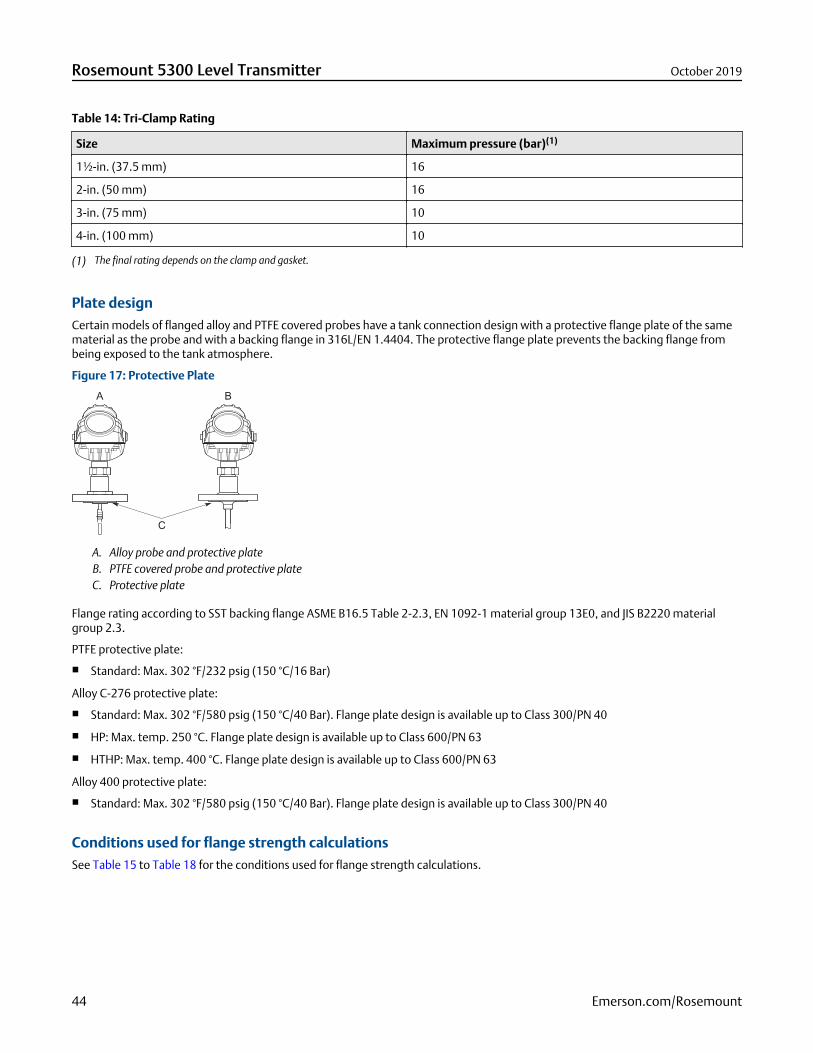
Table 14: Tri-Clamp Rating
Size Maximum pressure (bar)(1)
1½-in. (37.5 mm) 16
2-in. (50 mm) 16
3-in. (75 mm) 10
4-in. (100 mm) 10
(1) The final rating depends on the clamp and gasket.
Plate designCertain models of flanged alloy and PTFE covered probes have a tank connection design with a protective flange plate of the samematerial as the probe and with a backing flange in 316L/EN 1.4404. The protective flange plate prevents the backing flange frombeing exposed to the tank atmosphere.
Figure 17: Protective Plate
A. Alloy probe and protective plateB. PTFE covered probe and protective plateC. Protective plate
Flange rating according to SST backing flange ASME B16.5 Table 2-2.3, EN 1092-1 material group 13E0, and JIS B2220 materialgroup 2.3.
PTFE protective plate:
Standard: Max. 302 °F/232 psig (150 °C/16 Bar)
Alloy C-276 protective plate:
Standard: Max. 302 °F/580 psig (150 °C/40 Bar). Flange plate design is available up to Class 300/PN 40
HP: Max. temp. 250 °C. Flange plate design is available up to Class 600/PN 63
HTHP: Max. temp. 400 °C. Flange plate design is available up to Class 600/PN 63
Alloy 400 protective plate:
Standard: Max. 302 °F/580 psig (150 °C/40 Bar). Flange plate design is available up to Class 300/PN 40
Conditions used for flange strength calculationsSee Table 15 to Table 18 for the conditions used for flange strength calculations.
Rosemount 5300 Level Transmitter October 2019
44 Emerson.com/Rosemount

Table 15: 316/316L Flanges
Standard Bolting material Gasket Flange material Hub material
Standard/HP/HTHP/C
HP/HTHP/C
ASME Stainless steelSA193 B8M Cl.2
Soft (1a) with min.thickness 1.6 mm
Spiral woundgasket withnonmetallic filler(1b)
Stainless steel A182Gr. F316 and EN10222-5-1.4404
Stainless steelSA479M 316, andEN 10272-1.4404
EN, JIS EN 1515-1/-2 group13E0, A4-70
Soft (EN 1514-1)with min. thickness1.6 mm
Spiral woundgasket withnonmetallic filler(EN 1514-2)
Table 16: Process Connection with Plate Design
Standard Bolting material Gasket Flange material Hub material
Standard/HP/HTHP/C
HP/HTHP/C
ASME Stainless steelSA193 B8M Cl.2
Soft (1a) with min.thickness 1.6 mm
Spiral woundgasket withnonmetallic filler(1b)
Stainless steel A182Gr. F316L/F316 andEN 10222-5-1.4404
SB574 Gr. N10276or SB164 Gr.N04400
EN, JIS EN 1515-1/-2 group13E0, A4-70
Soft (EN 1514-1)with min. thickness1.6 mm
Spiral woundgasket withnonmetallic filler(EN 1514-2)
Table 17: Alloy C-276 Flanges
Standard Bolting material Gasket Flange material Hub material
Standard/HP/HTHP
HP/HTHP
ASME UNS N10276 Soft (1a) with min.thickness 1.6 mm
Spiral woundgasket withnonmetallic filler(1b)
SB462 Gr. N10276(solution annealedcondition) or SB575Gr. N10276(solution annealedcondition)
SB574 Gr. N10276
EN Soft (EN 1514-1)with min. thickness1.6 mm
Spiral woundgasket withnonmetallic filler(EN 1514-2)
October 2019 Rosemount 5300 Level Transmitter
Emerson.com/Rosemount 45
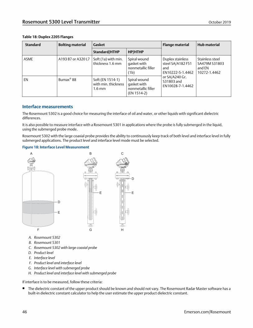
Table 18: Duplex 2205 Flanges
Standard Bolting material Gasket Flange material Hub material
Standard/HTHP HP/HTHP
ASME A193 B7 or A320 L7 Soft (1a) with min.thickness 1.6 mm
Spiral woundgasket withnonmetallic filler(1b)
Duplex stainlesssteel SA/A182 F51andEN10222-5-1.4462or SA/A240 Gr.S31803 andEN10028-7-1.4462
Stainless steelSA479M S31803and EN10272-1.4462
EN Bumax® 88 Soft (EN 1514-1)with min. thickness1.6 mm
Spiral woundgasket withnonmetallic filler(EN 1514-2)
Interface measurementsThe Rosemount 5302 is a good choice for measuring the interface of oil and water, or other liquids with significant dielectricdifferences.
It is also possible to measure interface with a Rosemount 5301 in applications where the probe is fully submerged in the liquid,using the submerged probe mode.
Rosemount 5302 with the large coaxial probe provides the ability to continuously keep track of both level and interface level in fullysubmerged applications. The product level and interface level mode must be selected.
Figure 18: Interface Level Measurement
A. Rosemount 5302B. Rosemount 5301C. Rosemount 5302 with large coaxial probeD. Product levelE. Interface levelF. Product level and interface level
G. Interface level with submerged probeH. Product level and interface level with submerged probe
If interface is to be measured, follow these criteria:
The dielectric constant of the upper product should be known and should not vary. The Rosemount Radar Master software has abuilt-in dielectric constant calculator to help the user estimate the upper product dielectric constant.
Rosemount 5300 Level Transmitter October 2019
46 Emerson.com/Rosemount
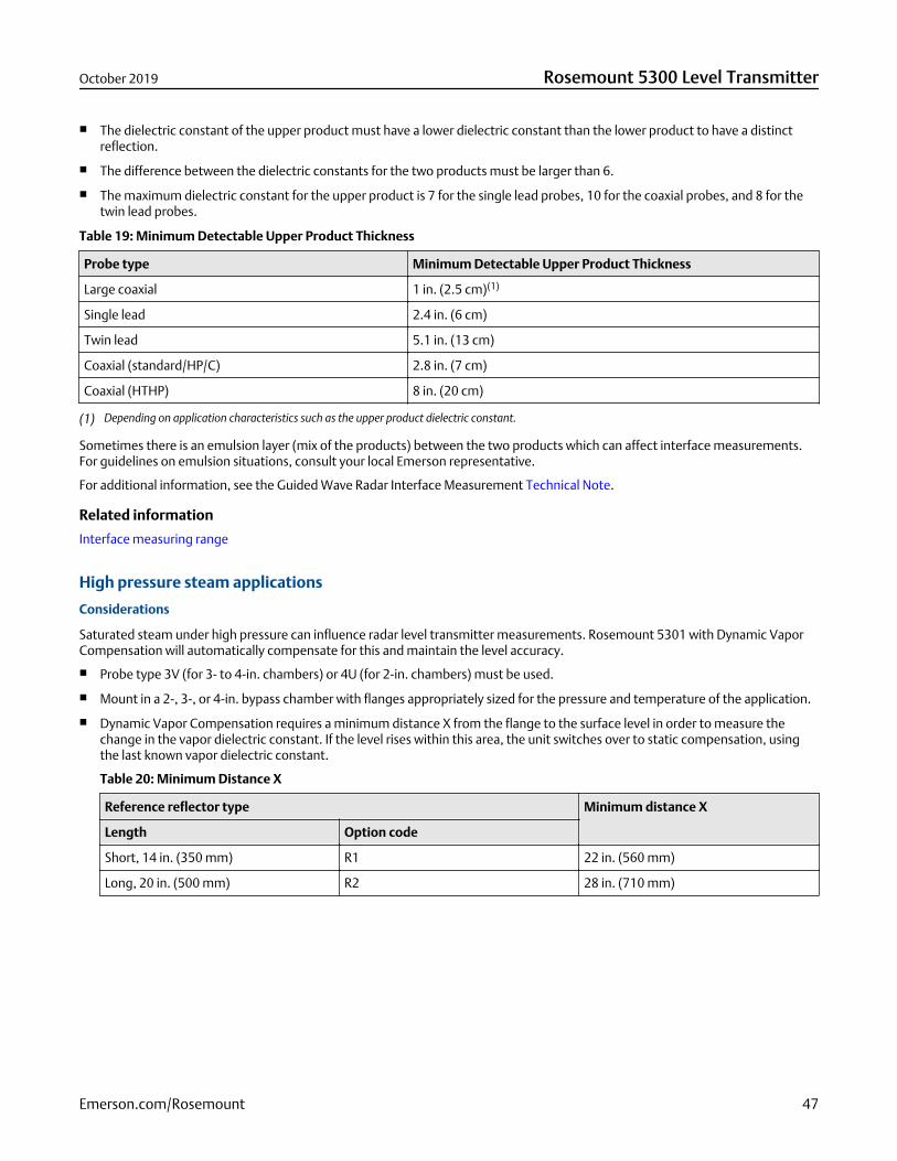
The dielectric constant of the upper product must have a lower dielectric constant than the lower product to have a distinctreflection.
The difference between the dielectric constants for the two products must be larger than 6.
The maximum dielectric constant for the upper product is 7 for the single lead probes, 10 for the coaxial probes, and 8 for thetwin lead probes.
Table 19: Minimum Detectable Upper Product Thickness
Probe type Minimum Detectable Upper Product Thickness
Large coaxial 1 in. (2.5 cm)(1)
Single lead 2.4 in. (6 cm)
Twin lead 5.1 in. (13 cm)
Coaxial (standard/HP/C) 2.8 in. (7 cm)
Coaxial (HTHP) 8 in. (20 cm)
(1) Depending on application characteristics such as the upper product dielectric constant.
Sometimes there is an emulsion layer (mix of the products) between the two products which can affect interface measurements.For guidelines on emulsion situations, consult your local Emerson representative.
For additional information, see the Guided Wave Radar Interface Measurement Technical Note.
Related information
Interface measuring range
High pressure steam applications
Considerations
Saturated steam under high pressure can influence radar level transmitter measurements. Rosemount 5301 with Dynamic VaporCompensation will automatically compensate for this and maintain the level accuracy.
Probe type 3V (for 3- to 4-in. chambers) or 4U (for 2-in. chambers) must be used.
Mount in a 2-, 3-, or 4-in. bypass chamber with flanges appropriately sized for the pressure and temperature of the application.
Dynamic Vapor Compensation requires a minimum distance X from the flange to the surface level in order to measure thechange in the vapor dielectric constant. If the level rises within this area, the unit switches over to static compensation, usingthe last known vapor dielectric constant.
Table 20: Minimum Distance X
Reference reflector type Minimum distance X
Length Option code
Short, 14 in. (350 mm) R1 22 in. (560 mm)
Long, 20 in. (500 mm) R2 28 in. (710 mm)
October 2019 Rosemount 5300 Level Transmitter
Emerson.com/Rosemount 47
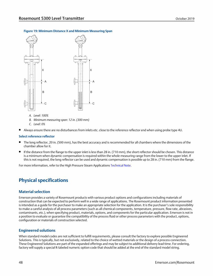
Figure 19: Minimum Distance X and Minimum Measuring Span
A. Level: 100%B. Minimum measuring span: 12 in. (300 mm)C. Level: 0%
Always ensure there are no disturbances from inlets etc. close to the reference reflector end when using probe type 4U.
Select reference reflector
The long reflector, 20 in. (500 mm), has the best accuracy and is recommended for all chambers where the dimensions of thechamber allow for it.
If the distance from the flange to the upper inlet is less than 28 in. (710 mm), the short reflector should be chosen. This distanceis a minimum when dynamic compensation is required within the whole measuring range from the lower to the upper inlet. Ifthis is not required, the long reflector can be used and dynamic compensation is possible up to 28 in. (710 mm) from the flange.
For more information, refer to the High Pressure Steam Applications Technical Note.
Physical specifications
Material selectionEmerson provides a variety of Rosemount products with various product options and configurations including materials ofconstruction that can be expected to perform well in a wide range of applications. The Rosemount product information presentedis intended as a guide for the purchaser to make an appropriate selection for the application. It is the purchaser’s sole responsibilityto make a careful analysis of all process parameters (such as all chemical components, temperature, pressure, flow rate, abrasives,contaminants, etc.), when specifying product, materials, options, and components for the particular application. Emerson is not ina position to evaluate or guarantee the compatibility of the process fluid or other process parameters with the product, options,configuration or materials of construction selected.
Engineered solutionsWhen standard model codes are not sufficient to fulfill requirements, please consult the factory to explore possible EngineeredSolutions. This is typically, but not exclusively, related to the choice of wetted materials or the design of a process connection.These Engineered Solutions are part of the expanded offerings and may be subject to additional delivery lead time. For ordering,factory will supply a special R-labeled numeric option code that should be added at the end of the standard model string.
Rosemount 5300 Level Transmitter October 2019
48 Emerson.com/Rosemount
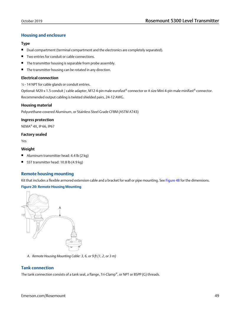
Housing and enclosure
Type Dual compartment (terminal compartment and the electronics are completely separated).
Two entries for conduit or cable connections.
The transmitter housing is separable from probe assembly.
The transmitter housing can be rotated in any direction.
Electrical connection
½ - 14 NPT for cable glands or conduit entries.
Optional: M20 x 1.5 conduit / cable adapter, M12 4-pin male eurofast® connector or A size Mini 4-pin male minifast® connector.
Recommended output cabling is twisted shielded pairs, 24-12 AWG.
Housing material
Polyurethane-covered Aluminum, or Stainless Steel Grade CF8M (ASTM A743)
Ingress protection
NEMA® 4X, IP 66, IP67
Factory sealed
Yes
Weight Aluminum transmitter head: 4.4 lb (2 kg)
SST transmitter head: 10.8 lb (4.9 kg)
Remote housing mountingKit that includes a flexible armored extension cable and a bracket for wall or pipe mounting. See Figure 48 for the dimensions.
Figure 20: Remote Housing Mounting
A. Remote Housing Mounting Cable: 3, 6, or 9 ft (1, 2, or 3 m)
Tank connectionThe tank connection consists of a tank seal, a flange, Tri-Clamp®, or NPT or BSPP (G) threads.
October 2019 Rosemount 5300 Level Transmitter
Emerson.com/Rosemount 49
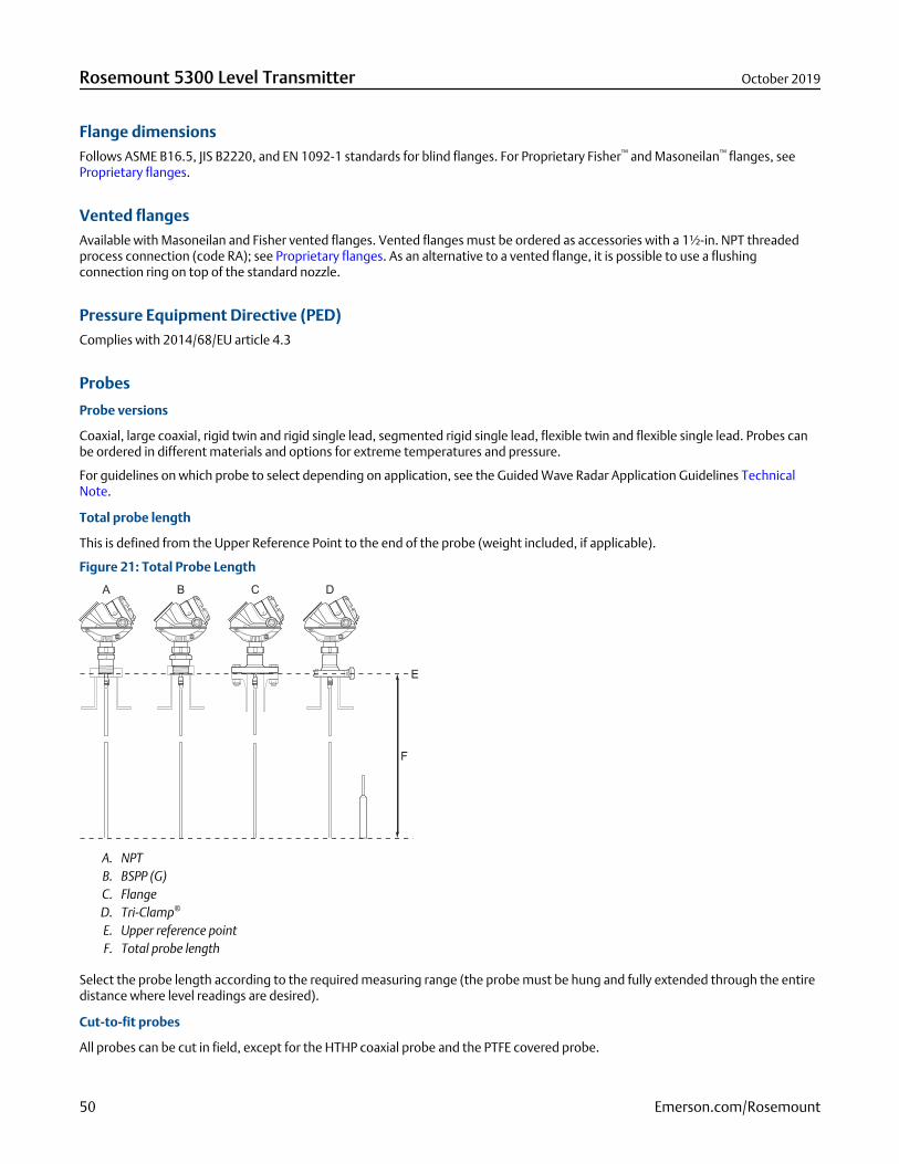
Flange dimensionsFollows ASME B16.5, JIS B2220, and EN 1092-1 standards for blind flanges. For Proprietary Fisher™ and Masoneilan™ flanges, seeProprietary flanges.
Vented flangesAvailable with Masoneilan and Fisher vented flanges. Vented flanges must be ordered as accessories with a 1½-in. NPT threadedprocess connection (code RA); see Proprietary flanges. As an alternative to a vented flange, it is possible to use a flushingconnection ring on top of the standard nozzle.
Pressure Equipment Directive (PED)Complies with 2014/68/EU article 4.3
Probes
Probe versions
Coaxial, large coaxial, rigid twin and rigid single lead, segmented rigid single lead, flexible twin and flexible single lead. Probes canbe ordered in different materials and options for extreme temperatures and pressure.
For guidelines on which probe to select depending on application, see the Guided Wave Radar Application Guidelines TechnicalNote.
Total probe length
This is defined from the Upper Reference Point to the end of the probe (weight included, if applicable).
Figure 21: Total Probe Length
A. NPTB. BSPP (G)C. FlangeD. Tri-Clamp®
E. Upper reference pointF. Total probe length
Select the probe length according to the required measuring range (the probe must be hung and fully extended through the entiredistance where level readings are desired).
Cut-to-fit probes
All probes can be cut in field, except for the HTHP coaxial probe and the PTFE covered probe.
Rosemount 5300 Level Transmitter October 2019
50 Emerson.com/Rosemount
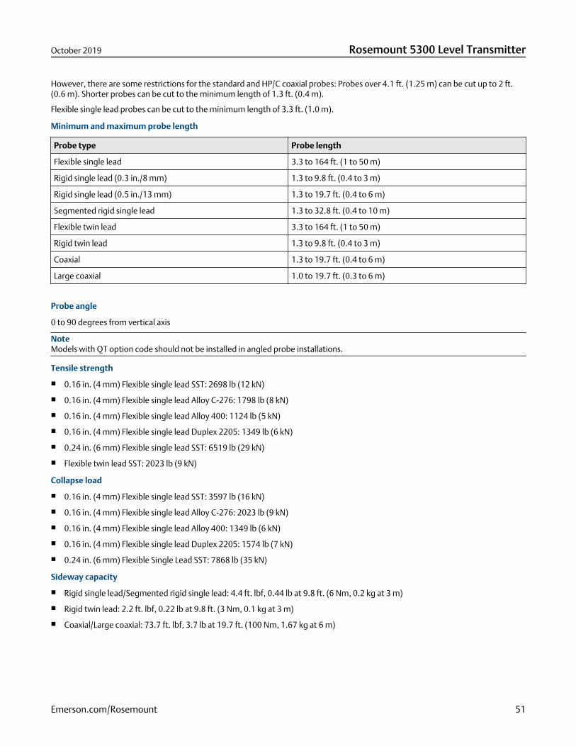
However, there are some restrictions for the standard and HP/C coaxial probes: Probes over 4.1 ft. (1.25 m) can be cut up to 2 ft.(0.6 m). Shorter probes can be cut to the minimum length of 1.3 ft. (0.4 m).
Flexible single lead probes can be cut to the minimum length of 3.3 ft. (1.0 m).
Minimum and maximum probe length
Probe type Probe length
Flexible single lead 3.3 to 164 ft. (1 to 50 m)
Rigid single lead (0.3 in./8 mm) 1.3 to 9.8 ft. (0.4 to 3 m)
Rigid single lead (0.5 in./13 mm) 1.3 to 19.7 ft. (0.4 to 6 m)
Segmented rigid single lead 1.3 to 32.8 ft. (0.4 to 10 m)
Flexible twin lead 3.3 to 164 ft. (1 to 50 m)
Rigid twin lead 1.3 to 9.8 ft. (0.4 to 3 m)
Coaxial 1.3 to 19.7 ft. (0.4 to 6 m)
Large coaxial 1.0 to 19.7 ft. (0.3 to 6 m)
Probe angle
0 to 90 degrees from vertical axis
NoteModels with QT option code should not be installed in angled probe installations.
Tensile strength
0.16 in. (4 mm) Flexible single lead SST: 2698 lb (12 kN)
0.16 in. (4 mm) Flexible single lead Alloy C-276: 1798 lb (8 kN)
0.16 in. (4 mm) Flexible single lead Alloy 400: 1124 lb (5 kN)
0.16 in. (4 mm) Flexible single lead Duplex 2205: 1349 lb (6 kN)
0.24 in. (6 mm) Flexible single lead SST: 6519 lb (29 kN)
Flexible twin lead SST: 2023 lb (9 kN)
Collapse load
0.16 in. (4 mm) Flexible single lead SST: 3597 lb (16 kN)
0.16 in. (4 mm) Flexible single lead Alloy C-276: 2023 lb (9 kN)
0.16 in. (4 mm) Flexible single lead Alloy 400: 1349 lb (6 kN)
0.16 in. (4 mm) Flexible single lead Duplex 2205: 1574 lb (7 kN)
0.24 in. (6 mm) Flexible Single Lead SST: 7868 lb (35 kN)
Sideway capacity
Rigid single lead/Segmented rigid single lead: 4.4 ft. lbf, 0.44 lb at 9.8 ft. (6 Nm, 0.2 kg at 3 m)
Rigid twin lead: 2.2 ft. lbf, 0.22 lb at 9.8 ft. (3 Nm, 0.1 kg at 3 m)
Coaxial/Large coaxial: 73.7 ft. lbf, 3.7 lb at 19.7 ft. (100 Nm, 1.67 kg at 6 m)
October 2019 Rosemount 5300 Level Transmitter
Emerson.com/Rosemount 51
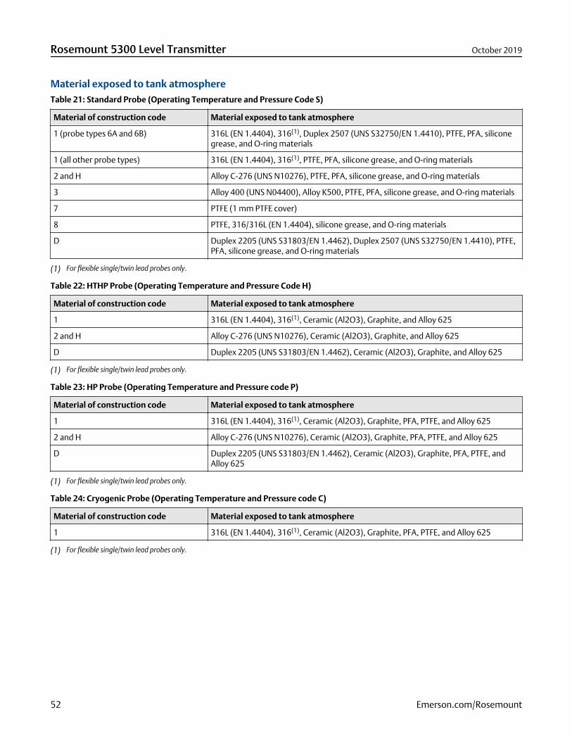
Material exposed to tank atmosphereTable 21: Standard Probe (Operating Temperature and Pressure Code S)
Material of construction code Material exposed to tank atmosphere
1 (probe types 6A and 6B) 316L (EN 1.4404), 316(1), Duplex 2507 (UNS S32750/EN 1.4410), PTFE, PFA, siliconegrease, and O-ring materials
1 (all other probe types) 316L (EN 1.4404), 316(1), PTFE, PFA, silicone grease, and O-ring materials
2 and H Alloy C-276 (UNS N10276), PTFE, PFA, silicone grease, and O-ring materials
3 Alloy 400 (UNS N04400), Alloy K500, PTFE, PFA, silicone grease, and O-ring materials
7 PTFE (1 mm PTFE cover)
8 PTFE, 316/316L (EN 1.4404), silicone grease, and O-ring materials
D Duplex 2205 (UNS S31803/EN 1.4462), Duplex 2507 (UNS S32750/EN 1.4410), PTFE,PFA, silicone grease, and O-ring materials
(1) For flexible single/twin lead probes only.
Table 22: HTHP Probe (Operating Temperature and Pressure Code H)
Material of construction code Material exposed to tank atmosphere
1 316L (EN 1.4404), 316(1), Ceramic (Al2O3), Graphite, and Alloy 625
2 and H Alloy C-276 (UNS N10276), Ceramic (Al2O3), Graphite, and Alloy 625
D Duplex 2205 (UNS S31803/EN 1.4462), Ceramic (Al2O3), Graphite, and Alloy 625
(1) For flexible single/twin lead probes only.
Table 23: HP Probe (Operating Temperature and Pressure code P)
Material of construction code Material exposed to tank atmosphere
1 316L (EN 1.4404), 316(1), Ceramic (Al2O3), Graphite, PFA, PTFE, and Alloy 625
2 and H Alloy C-276 (UNS N10276), Ceramic (Al2O3), Graphite, PFA, PTFE, and Alloy 625
D Duplex 2205 (UNS S31803/EN 1.4462), Ceramic (Al2O3), Graphite, PFA, PTFE, andAlloy 625
(1) For flexible single/twin lead probes only.
Table 24: Cryogenic Probe (Operating Temperature and Pressure code C)
Material of construction code Material exposed to tank atmosphere
1 316L (EN 1.4404), 316(1), Ceramic (Al2O3), Graphite, PFA, PTFE, and Alloy 625
(1) For flexible single/twin lead probes only.
Rosemount 5300 Level Transmitter October 2019
52 Emerson.com/Rosemount
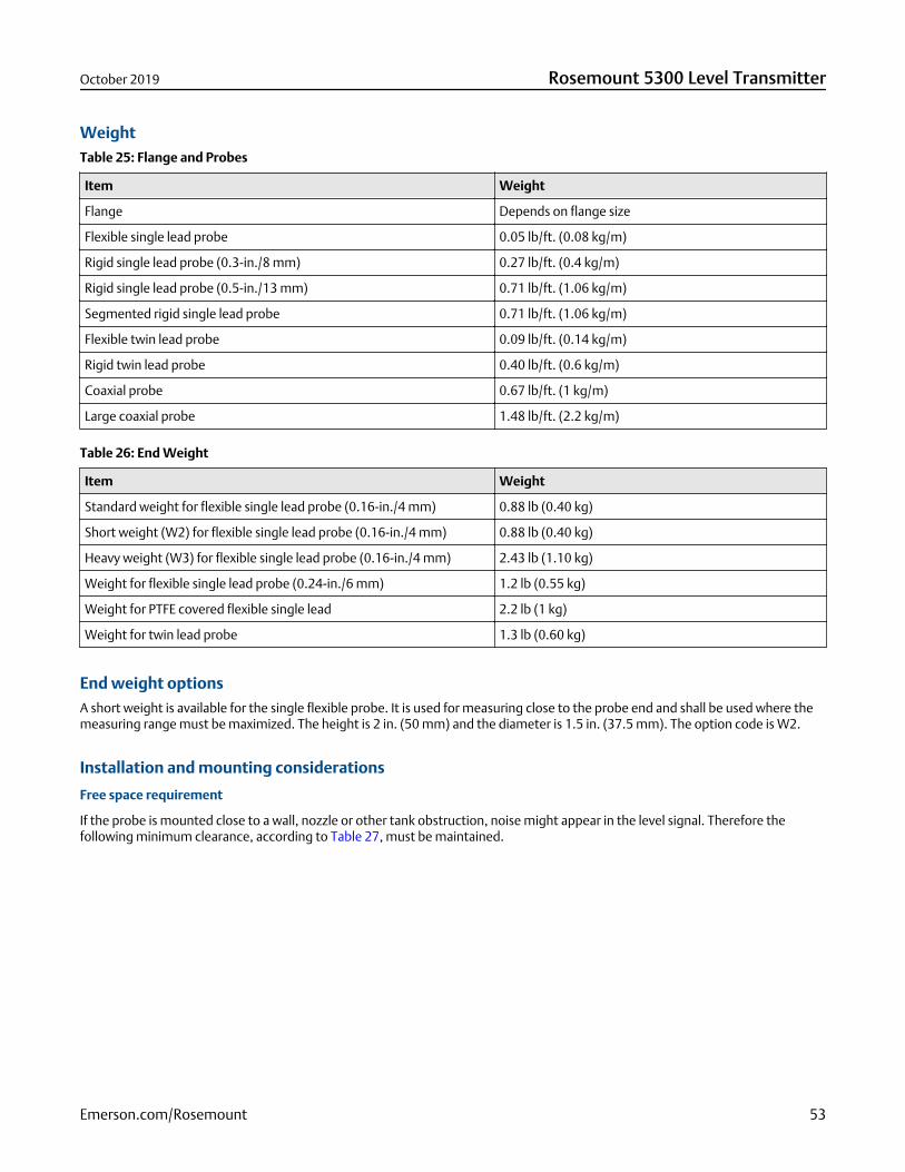
WeightTable 25: Flange and Probes
Item Weight
Flange Depends on flange size
Flexible single lead probe 0.05 lb/ft. (0.08 kg/m)
Rigid single lead probe (0.3-in./8 mm) 0.27 lb/ft. (0.4 kg/m)
Rigid single lead probe (0.5-in./13 mm) 0.71 lb/ft. (1.06 kg/m)
Segmented rigid single lead probe 0.71 lb/ft. (1.06 kg/m)
Flexible twin lead probe 0.09 lb/ft. (0.14 kg/m)
Rigid twin lead probe 0.40 lb/ft. (0.6 kg/m)
Coaxial probe 0.67 lb/ft. (1 kg/m)
Large coaxial probe 1.48 lb/ft. (2.2 kg/m)
Table 26: End Weight
Item Weight
Standard weight for flexible single lead probe (0.16-in./4 mm) 0.88 lb (0.40 kg)
Short weight (W2) for flexible single lead probe (0.16-in./4 mm) 0.88 lb (0.40 kg)
Heavy weight (W3) for flexible single lead probe (0.16-in./4 mm) 2.43 lb (1.10 kg)
Weight for flexible single lead probe (0.24-in./6 mm) 1.2 lb (0.55 kg)
Weight for PTFE covered flexible single lead 2.2 lb (1 kg)
Weight for twin lead probe 1.3 lb (0.60 kg)
End weight optionsA short weight is available for the single flexible probe. It is used for measuring close to the probe end and shall be used where themeasuring range must be maximized. The height is 2 in. (50 mm) and the diameter is 1.5 in. (37.5 mm). The option code is W2.
Installation and mounting considerations
Free space requirement
If the probe is mounted close to a wall, nozzle or other tank obstruction, noise might appear in the level signal. Therefore thefollowing minimum clearance, according to Table 27, must be maintained.
October 2019 Rosemount 5300 Level Transmitter
Emerson.com/Rosemount 53
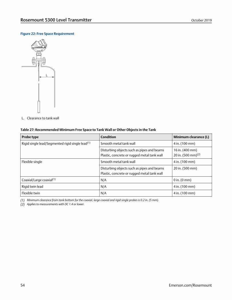
Figure 22: Free Space Requirement
L. Clearance to tank wall
Table 27: Recommended Minimum Free Space to Tank Wall or Other Objects in the Tank
Probe type Condition Minimum clearance (L)
Rigid single lead/Segmented rigid single lead(1) Smooth metal tank wall 4 in. (100 mm)
Disturbing objects such as pipes and beams
Plastic, concrete or rugged metal tank wall
16 in. (400 mm)
20 in. (500 mm)(2)
Flexible single Smooth metal tank wall 4 in. (100 mm)
Disturbing objects such as pipes and beams
Plastic, concrete or rugged metal tank wall
20 in. (500 mm)
Coaxial/Large coaxial(1) N/A 0 in. (0 mm)
Rigid twin lead N/A 4 in. (100 mm)
Flexible twin N/A 4 in. (100 mm)
(1) Minimum clearance from tank bottom for the coaxial, large coaxial and rigid single probes is 0.2 in. (5 mm).(2) Applies to measurements with DC 1.4 or lower.
Rosemount 5300 Level Transmitter October 2019
54 Emerson.com/Rosemount
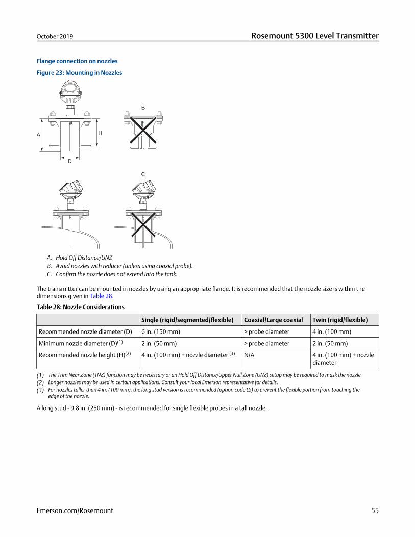
Flange connection on nozzles
Figure 23: Mounting in Nozzles
A. Hold Off Distance/UNZB. Avoid nozzles with reducer (unless using coaxial probe).C. Confirm the nozzle does not extend into the tank.
The transmitter can be mounted in nozzles by using an appropriate flange. It is recommended that the nozzle size is within thedimensions given in Table 28.
Table 28: Nozzle Considerations
Single (rigid/segmented/flexible) Coaxial/Large coaxial Twin (rigid/flexible)
Recommended nozzle diameter (D) 6 in. (150 mm) > probe diameter 4 in. (100 mm)
Minimum nozzle diameter (D)(1) 2 in. (50 mm) > probe diameter 2 in. (50 mm)
Recommended nozzle height (H)(2) 4 in. (100 mm) + nozzle diameter (3) N/A 4 in. (100 mm) + nozzlediameter
(1) The Trim Near Zone (TNZ) function may be necessary or an Hold Off Distance/Upper Null Zone (UNZ) setup may be required to mask the nozzle.(2) Longer nozzles may be used in certain applications. Consult your local Emerson representative for details.(3) For nozzles taller than 4 in. (100 mm), the long stud version is recommended (option code LS) to prevent the flexible portion from touching the
edge of the nozzle.
A long stud - 9.8 in. (250 mm) - is recommended for single flexible probes in a tall nozzle.
October 2019 Rosemount 5300 Level Transmitter
Emerson.com/Rosemount 55
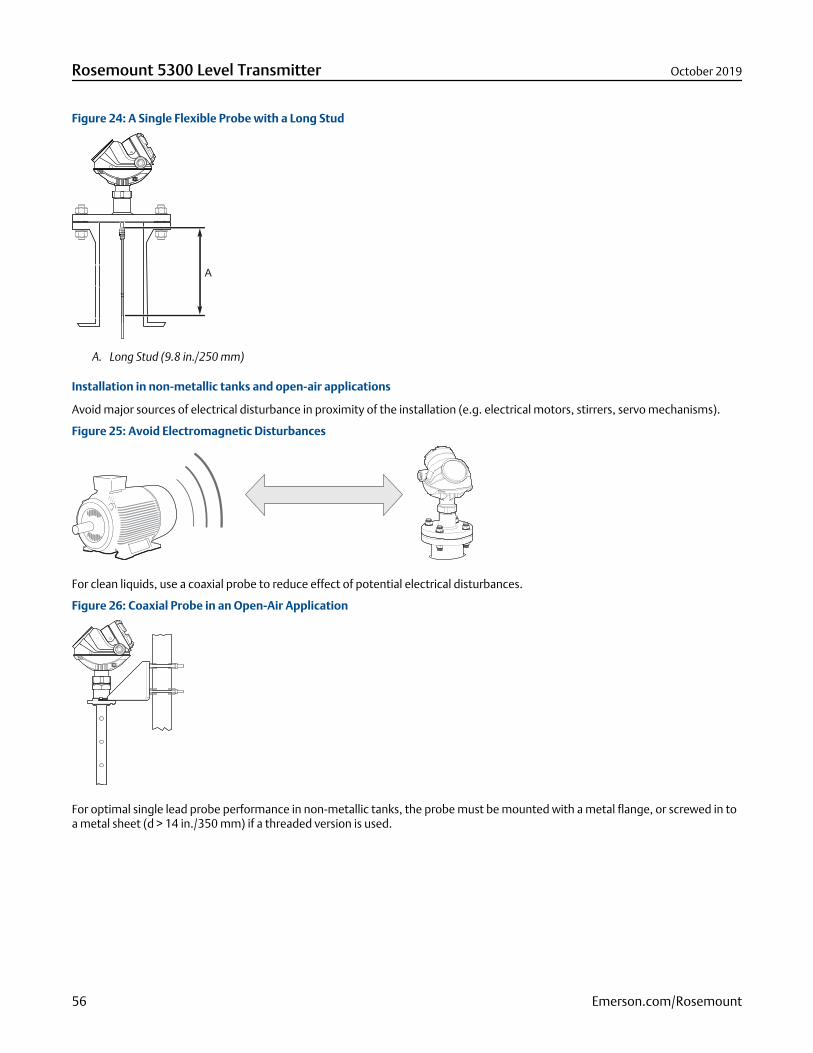
Figure 24: A Single Flexible Probe with a Long Stud
A. Long Stud (9.8 in./250 mm)
Installation in non-metallic tanks and open-air applications
Avoid major sources of electrical disturbance in proximity of the installation (e.g. electrical motors, stirrers, servo mechanisms).
Figure 25: Avoid Electromagnetic Disturbances
For clean liquids, use a coaxial probe to reduce effect of potential electrical disturbances.
Figure 26: Coaxial Probe in an Open-Air Application
For optimal single lead probe performance in non-metallic tanks, the probe must be mounted with a metal flange, or screwed in toa metal sheet (d > 14 in./350 mm) if a threaded version is used.
Rosemount 5300 Level Transmitter October 2019
56 Emerson.com/Rosemount
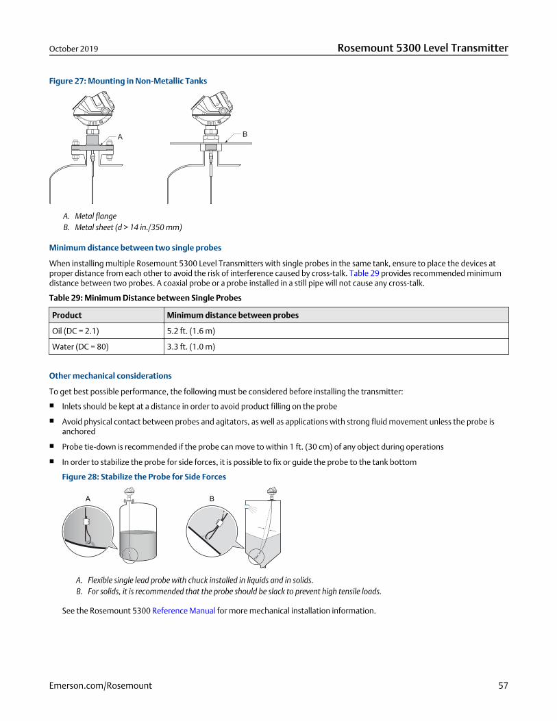
Figure 27: Mounting in Non-Metallic Tanks
A. Metal flangeB. Metal sheet (d > 14 in./350 mm)
Minimum distance between two single probes
When installing multiple Rosemount 5300 Level Transmitters with single probes in the same tank, ensure to place the devices atproper distance from each other to avoid the risk of interference caused by cross-talk. Table 29 provides recommended minimumdistance between two probes. A coaxial probe or a probe installed in a still pipe will not cause any cross-talk.
Table 29: Minimum Distance between Single Probes
Product Minimum distance between probes
Oil (DC = 2.1) 5.2 ft. (1.6 m)
Water (DC = 80) 3.3 ft. (1.0 m)
Other mechanical considerations
To get best possible performance, the following must be considered before installing the transmitter:
Inlets should be kept at a distance in order to avoid product filling on the probe
Avoid physical contact between probes and agitators, as well as applications with strong fluid movement unless the probe isanchored
Probe tie-down is recommended if the probe can move to within 1 ft. (30 cm) of any object during operations
In order to stabilize the probe for side forces, it is possible to fix or guide the probe to the tank bottom
Figure 28: Stabilize the Probe for Side Forces
A. Flexible single lead probe with chuck installed in liquids and in solids.B. For solids, it is recommended that the probe should be slack to prevent high tensile loads.
See the Rosemount 5300 Reference Manual for more mechanical installation information.
October 2019 Rosemount 5300 Level Transmitter
Emerson.com/Rosemount 57
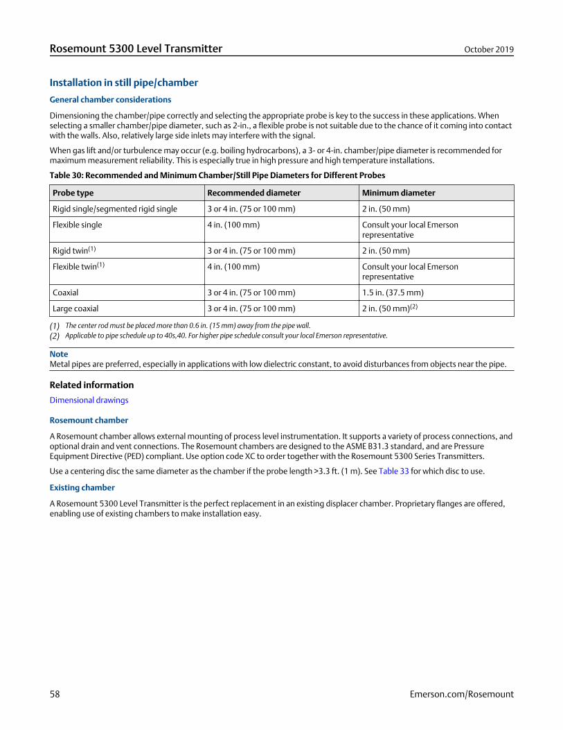
Installation in still pipe/chamber
General chamber considerations
Dimensioning the chamber/pipe correctly and selecting the appropriate probe is key to the success in these applications. Whenselecting a smaller chamber/pipe diameter, such as 2-in., a flexible probe is not suitable due to the chance of it coming into contactwith the walls. Also, relatively large side inlets may interfere with the signal.
When gas lift and/or turbulence may occur (e.g. boiling hydrocarbons), a 3- or 4-in. chamber/pipe diameter is recommended formaximum measurement reliability. This is especially true in high pressure and high temperature installations.
Table 30: Recommended and Minimum Chamber/Still Pipe Diameters for Different Probes
Probe type Recommended diameter Minimum diameter
Rigid single/segmented rigid single 3 or 4 in. (75 or 100 mm) 2 in. (50 mm)
Flexible single 4 in. (100 mm) Consult your local Emersonrepresentative
Rigid twin(1) 3 or 4 in. (75 or 100 mm) 2 in. (50 mm)
Flexible twin(1) 4 in. (100 mm) Consult your local Emersonrepresentative
Coaxial 3 or 4 in. (75 or 100 mm) 1.5 in. (37.5 mm)
Large coaxial 3 or 4 in. (75 or 100 mm) 2 in. (50 mm)(2)
(1) The center rod must be placed more than 0.6 in. (15 mm) away from the pipe wall.(2) Applicable to pipe schedule up to 40s,40. For higher pipe schedule consult your local Emerson representative.
NoteMetal pipes are preferred, especially in applications with low dielectric constant, to avoid disturbances from objects near the pipe.
Related information
Dimensional drawings
Rosemount chamber
A Rosemount chamber allows external mounting of process level instrumentation. It supports a variety of process connections, andoptional drain and vent connections. The Rosemount chambers are designed to the ASME B31.3 standard, and are PressureEquipment Directive (PED) compliant. Use option code XC to order together with the Rosemount 5300 Series Transmitters.
Use a centering disc the same diameter as the chamber if the probe length >3.3 ft. (1 m). See Table 33 for which disc to use.
Existing chamber
A Rosemount 5300 Level Transmitter is the perfect replacement in an existing displacer chamber. Proprietary flanges are offered,enabling use of existing chambers to make installation easy.
Rosemount 5300 Level Transmitter October 2019
58 Emerson.com/Rosemount
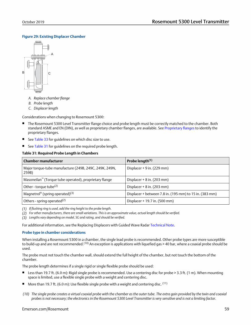
Figure 29: Existing Displacer Chamber
A. Replace chamber flangeB. Probe lengthC. Displacer length
Considerations when changing to Rosemount 5300:
The Rosemount 5300 Level Transmitter flange choice and probe length must be correctly matched to the chamber. Bothstandard ASME and EN (DIN), as well as proprietary chamber flanges, are available. See Proprietary flanges to identify theproprietary flanges.
See Table 33 for guidelines on which disc size to use.
See Table 31 for guidelines on the required probe length.
Table 31: Required Probe Length in Chambers
Chamber manufacturer Probe length(1)
Major torque-tube manufacture (249B, 249C, 249K, 249N,259B)
Displacer + 9 in. (229 mm)
Masoneilan™ (Torque tube operated), proprietary flange Displacer + 8 in. (203 mm)
Other - torque tube(2) Displacer + 8 in. (203 mm)
Magnetrol® (spring operated)(3) Displacer + between 7.8 in. (195 mm) to 15 in. (383 mm)
Others - spring operated(2) Displacer + 19.7 in. (500 mm)
(1) If flushing ring is used, add the ring height to the probe length.(2) For other manufacturers, there are small variations. This is an approximate value, actual length should be verified.(3) Lengths vary depending on model, SG and rating, and should be verified.
For additional information, see the Replacing Displacers with Guided Wave Radar Technical Note.
Probe type in chamber considerations
When installing a Rosemount 5300 in a chamber, the single lead probe is recommended. Other probe types are more susceptibleto build-up and are not recommended.(10) An exception is applications with liquefied gas > 40 bar, where a coaxial probe should beused.
The probe must not touch the chamber wall, should extend the full height of the chamber, but not touch the bottom of thechamber.
The probe length determines if a single rigid or single flexible probe should be used:
Less than 19.7 ft. (6.0 m): Rigid single probe is recommended. Use a centering disc for probe > 3.3 ft. (1 m). When mountingspace is limited, use a flexible single probe with a weight and centering disc.
More than 19.7 ft. (6.0 m): Use flexible single probe with a weight and centering disc. (11)
(10) The single probe creates a virtual coaxial probe with the chamber as the outer tube. The extra gain provided by the twin and coaxialprobes is not necessary; the electronics in the Rosemount 5300 Level Transmitter is very sensitive and is not a limiting factor.
October 2019 Rosemount 5300 Level Transmitter
Emerson.com/Rosemount 59
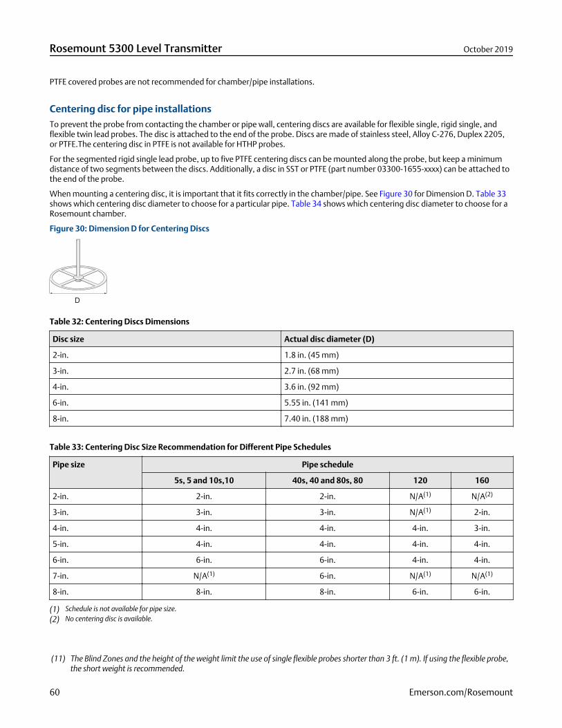
PTFE covered probes are not recommended for chamber/pipe installations.
Centering disc for pipe installationsTo prevent the probe from contacting the chamber or pipe wall, centering discs are available for flexible single, rigid single, andflexible twin lead probes. The disc is attached to the end of the probe. Discs are made of stainless steel, Alloy C-276, Duplex 2205,or PTFE.The centering disc in PTFE is not available for HTHP probes.
For the segmented rigid single lead probe, up to five PTFE centering discs can be mounted along the probe, but keep a minimumdistance of two segments between the discs. Additionally, a disc in SST or PTFE (part number 03300-1655-xxxx) can be attached tothe end of the probe.
When mounting a centering disc, it is important that it fits correctly in the chamber/pipe. See Figure 30 for Dimension D. Table 33shows which centering disc diameter to choose for a particular pipe. Table 34 shows which centering disc diameter to choose for aRosemount chamber.
Figure 30: Dimension D for Centering Discs
Table 32: Centering Discs Dimensions
Disc size Actual disc diameter (D)
2-in. 1.8 in. (45 mm)
3-in. 2.7 in. (68 mm)
4-in. 3.6 in. (92 mm)
6-in. 5.55 in. (141 mm)
8-in. 7.40 in. (188 mm)
Table 33: Centering Disc Size Recommendation for Different Pipe Schedules
Pipe size Pipe schedule
5s, 5 and 10s,10 40s, 40 and 80s, 80 120 160
2-in. 2-in. 2-in. N/A(1) N/A(2)
3-in. 3-in. 3-in. N/A(1) 2-in.
4-in. 4-in. 4-in. 4-in. 3-in.
5-in. 4-in. 4-in. 4-in. 4-in.
6-in. 6-in. 6-in. 4-in. 4-in.
7-in. N/A(1) 6-in. N/A(1) N/A(1)
8-in. 8-in. 8-in. 6-in. 6-in.
(1) Schedule is not available for pipe size.(2) No centering disc is available.
(11) The Blind Zones and the height of the weight limit the use of single flexible probes shorter than 3 ft. (1 m). If using the flexible probe,the short weight is recommended.
Rosemount 5300 Level Transmitter October 2019
60 Emerson.com/Rosemount
Table 34: Centering Disc Size Recommendations for Rosemount Chambers
Chamber size Chamber rating Centering disc
3-in. Up to Class 600/PN 100 3-in.
Class 900, 1500/PN160, 250 2-in.
3-in. T-piece Up to Class 600/PN 100 2-in.
4-in. Up to Class 600/PN 100 4-in.
Class 900, 1500/PN160, 250 3-in.
October 2019 Rosemount 5300 Level Transmitter
Emerson.com/Rosemount 61
Product certificationsRev 10.15
European directive informationA copy of the EU Declaration of Conformity can be found at the end of the Quick Start Guide. The most recent revision of the EUDeclaration of Conformity can be found at Emerson.com/Rosemount.
Safety Instrumented Systems (SIS)SIL 3 Capable: IEC 61508 certified for use in safety instrumented systems up to SIL 3 (Minimum requirement of single use (1oo1) forSIL 2 and redundant use (1oo2) for SIL 3).
Ordinary location certificationAs standard, the transmitter has been examined and tested to determine that the design meets the basic electrical, mechanical,and fire protection requirements by a nationally recognized test laboratory (NRTL) as accredited by the Federal Occupational Safetyand Health Administration (OSHA).
Installing equipment in North AmericaThe US National Electrical Code® (NEC) and the Canadian Electrical Code (CEC) permit the use of Division marked equipment inZones and Zone marked equipment in Divisions. The markings must be suitable for the area classification, gas, and temperatureclass. This information is clearly defined in the respective codes.
USA
E5 Explosionproof (XP), Dust-Ignitionproof (DIP)
Certificate FM16US0444X
Standards FM Class 3600 – 2018; FM Class 3610 – 2010; FM Class 3611 – 2004; FM Class 3615 – 2006; FM Class 3810 –2005; ANSI/ISA 60079-0 – 2013; ANSI/ISA 60079-11 – 2012; ANSI/NEMA® 250 – 2003;
Markings XP CL I, DIV 1, GP B, C, D; DIP CLII/III, DIV 1, GP E, F, G; T4; -50 °C ≤ Ta ≤ 60 °C (FIELDBUS) / 70 °C (HART); Type4X
Special Conditions for Safe Use (X):
1. WARNING – Potential Electrostatic Charging Hazard – The enclosure contains non-metallic material. To prevent the risk forelectrostatic sparking the plastic surface should only be cleaned with a damp cloth.
2. WARNING – The apparatus enclosure contains aluminum and is considered to constitute a potential risk of ignition byimpact or friction. Care must be taken into account during installation and use to prevent impact or friction.
I5 Intrinsic Safety (IS), Nonincendive (NI)
Certificate FM16US0444X
Rosemount 5300 Level Transmitter October 2019
62 Emerson.com/Rosemount
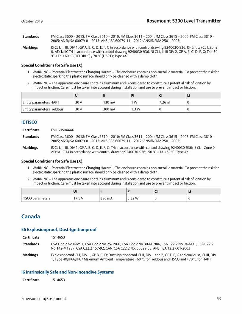
Standards FM Class 3600 – 2018; FM Class 3610 – 2010; FM Class 3611 – 2004; FM Class 3615 – 2006; FM Class 3810 –2005; ANSI/ISA 60079-0 – 2013; ANSI/ISA 60079-11 – 2012; ANSI/NEMA 250 – 2003;
Markings IS CL I, II, III, DIV 1, GP A, B, C, D, E, F, G in accordance with control drawing 9240030-936; IS (Entity) CL I, Zone0, AEx ia IIC T4 in accordance with control drawing 9240030-936, NI CL I, II, III DIV 2, GP A, B, C, D, F, G; T4; -50°C ≤ Ta ≤ 60 °C (FIELDBUS) / 70 °C (HART); Type 4X
Special Conditions for Safe Use (X):
1. WARNING – Potential Electrostatic Charging Hazard – The enclosure contains non-metallic material. To prevent the risk forelectrostatic sparking the plastic surface should only be cleaned with a damp cloth.
2. WARNING – The apparatus enclosure contains aluminum and is considered to constitute a potential risk of ignition byimpact or friction. Care must be taken into account during installation and use to prevent impact or friction.
Ui Ii Pi Ci Li
Entity parameters HART 30 V 130 mA 1 W 7.26 nF 0
Entity parameters Fieldbus 30 V 300 mA 1.3 W 0 0
IE FISCO
Certificate FM16US0444X
Standards FM Class 3600 – 2018; FM Class 3610 – 2010; FM Class 3611 – 2004; FM Class 3615 – 2006; FM Class 3810 –2005; ANSI/ISA 60079-0 – 2013; ANSI/ISA 60079-11 – 2012; ANSI/NEMA 250 – 2003;
Markings IS CL I, II, III, DIV 1, GP A, B, C, D, E, F, G; T4; in accordance with control drawing 9240030-936; IS CL I, Zone 0AEx ia IIC T4 in accordance with control drawing 9240030-936; -50 °C ≤ Ta ≤ 60 °C; Type 4X
Special Conditions for Safe Use (X):
1. WARNING – Potential Electrostatic Charging Hazard – The enclosure contains non-metallic material. To prevent the risk forelectrostatic sparking the plastic surface should only be cleaned with a damp cloth.
2. WARNING – The apparatus enclosure contains aluminum and is considered to constitute a potential risk of ignition byimpact or friction. Care must be taken into account during installation and use to prevent impact or friction.
Ui Ii Pi Ci Li
FISCO parameters 17.5 V 380 mA 5.32 W 0 0
Canada
E6 Explosionproof, Dust-Ignitionproof
Certificate 1514653
Standards CSA C22.2 No.0-M91, CSA C22.2 No.25-1966, CSA C22.2 No.30-M1986, CSA C22.2 No.94-M91, CSA C22.2No.142-M1987, CSA C22.2 157-92, CAN/CSA C22.2 No. 60529:05, ANSI/ISA 12.27.01-2003
Markings Explosionproof CL I, DIV 1, GP B, C, D; Dust-Ignitionproof CL II, DIV 1 and 2, GP E, F, G and coal dust, CL III, DIV1, Type 4X/IP66/IP67 Maximum Ambient Temperature +60 °C for Fieldbus and FISCO and +70 °C for HART
I6 Intrinsically Safe and Non-Incendive Systems
Certificate 1514653
October 2019 Rosemount 5300 Level Transmitter
Emerson.com/Rosemount 63
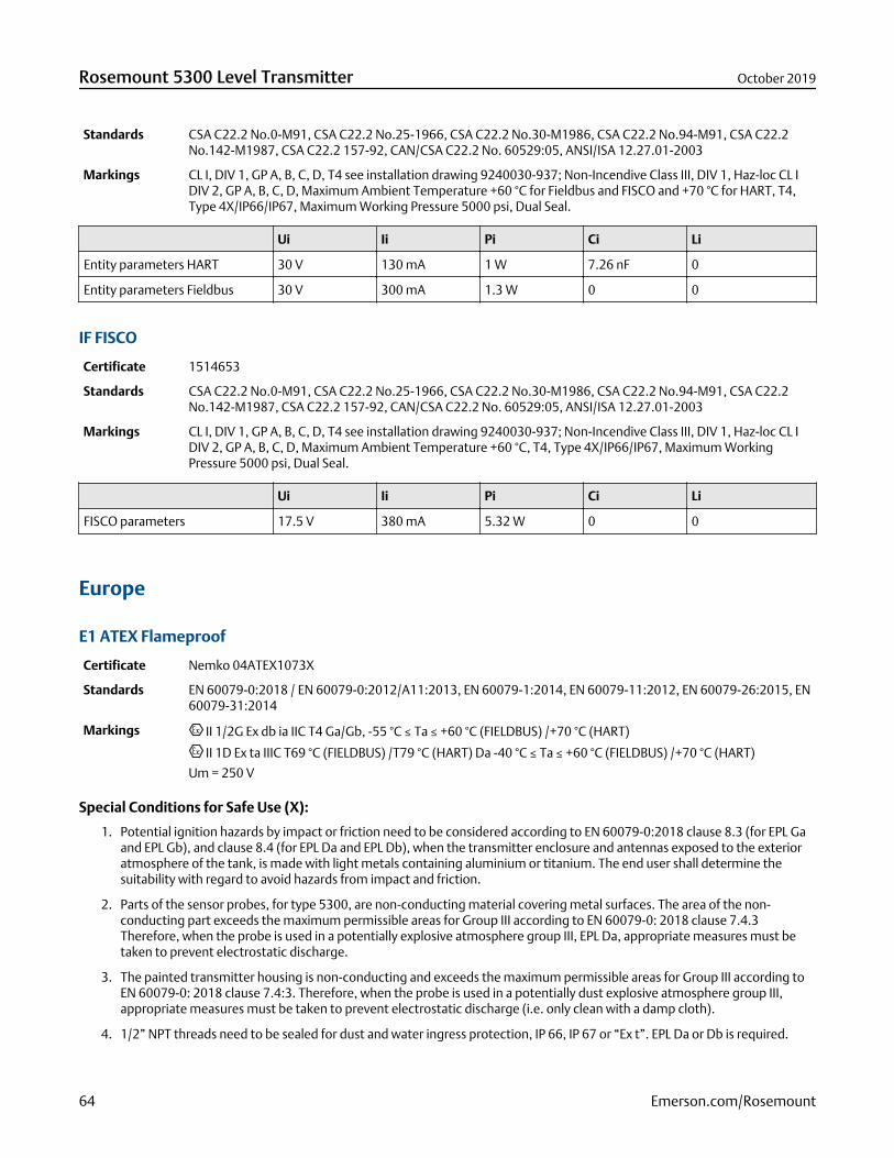
Standards CSA C22.2 No.0-M91, CSA C22.2 No.25-1966, CSA C22.2 No.30-M1986, CSA C22.2 No.94-M91, CSA C22.2No.142-M1987, CSA C22.2 157-92, CAN/CSA C22.2 No. 60529:05, ANSI/ISA 12.27.01-2003
Markings CL I, DIV 1, GP A, B, C, D, T4 see installation drawing 9240030-937; Non-Incendive Class III, DIV 1, Haz-loc CL IDIV 2, GP A, B, C, D, Maximum Ambient Temperature +60 °C for Fieldbus and FISCO and +70 °C for HART, T4,Type 4X/IP66/IP67, Maximum Working Pressure 5000 psi, Dual Seal.
Ui Ii Pi Ci Li
Entity parameters HART 30 V 130 mA 1 W 7.26 nF 0
Entity parameters Fieldbus 30 V 300 mA 1.3 W 0 0
IF FISCO
Certificate 1514653
Standards CSA C22.2 No.0-M91, CSA C22.2 No.25-1966, CSA C22.2 No.30-M1986, CSA C22.2 No.94-M91, CSA C22.2No.142-M1987, CSA C22.2 157-92, CAN/CSA C22.2 No. 60529:05, ANSI/ISA 12.27.01-2003
Markings CL I, DIV 1, GP A, B, C, D, T4 see installation drawing 9240030-937; Non-Incendive Class III, DIV 1, Haz-loc CL IDIV 2, GP A, B, C, D, Maximum Ambient Temperature +60 °C, T4, Type 4X/IP66/IP67, Maximum WorkingPressure 5000 psi, Dual Seal.
Ui Ii Pi Ci Li
FISCO parameters 17.5 V 380 mA 5.32 W 0 0
Europe
E1 ATEX Flameproof
Certificate Nemko 04ATEX1073X
Standards EN 60079-0:2018 / EN 60079-0:2012/A11:2013, EN 60079-1:2014, EN 60079-11:2012, EN 60079-26:2015, EN60079-31:2014
Markings II 1/2G Ex db ia IIC T4 Ga/Gb, -55 °C ≤ Ta ≤ +60 °C (FIELDBUS) /+70 °C (HART)
II 1D Ex ta IIIC T69 °C (FIELDBUS) /T79 °C (HART) Da -40 °C ≤ Ta ≤ +60 °C (FIELDBUS) /+70 °C (HART)
Um = 250 V
Special Conditions for Safe Use (X):
1. Potential ignition hazards by impact or friction need to be considered according to EN 60079-0:2018 clause 8.3 (for EPL Gaand EPL Gb), and clause 8.4 (for EPL Da and EPL Db), when the transmitter enclosure and antennas exposed to the exterioratmosphere of the tank, is made with light metals containing aluminium or titanium. The end user shall determine thesuitability with regard to avoid hazards from impact and friction.
2. Parts of the sensor probes, for type 5300, are non-conducting material covering metal surfaces. The area of the non-conducting part exceeds the maximum permissible areas for Group III according to EN 60079-0: 2018 clause 7.4.3Therefore, when the probe is used in a potentially explosive atmosphere group III, EPL Da, appropriate measures must betaken to prevent electrostatic discharge.
3. The painted transmitter housing is non-conducting and exceeds the maximum permissible areas for Group III according toEN 60079-0: 2018 clause 7.4:3. Therefore, when the probe is used in a potentially dust explosive atmosphere group III,appropriate measures must be taken to prevent electrostatic discharge (i.e. only clean with a damp cloth).
4. 1/2” NPT threads need to be sealed for dust and water ingress protection, IP 66, IP 67 or “Ex t”. EPL Da or Db is required.
Rosemount 5300 Level Transmitter October 2019
64 Emerson.com/Rosemount

I1 ATEX Intrinsic Safety
Certificate Nemko 04ATEX1073X
Standards EN 60079-0:2018 / EN 60079-0:2012/A11:2013, EN 60079-1:2014, EN 60079-11:2012, EN 60079-26:2015, EN60079-31:2014
Markings II 1G Ex ia IIC T4 Ga, -55 °C ≤ Ta ≤ +60 °C (FIELDBUS) /+70 °C (HART)
II 1D Ex ia IIIC T69 °C/T79 °C Da, -50 °C ≤ Ta ≤ +60 °C (FIELDBUS) /+70 °C (HART)
Special Conditions for Safe Use (X):
1. The intrinsically safe circuits do not withstand the 500V AC test as specified in EN 60079-11:2012 clause 6.3.13.
2. Potential ignition hazards by impact or friction need to be considered according to EN 60079-0:2018 clause 8.3 (for EPL Gaand EPL Gb), and clause 8.4 (for EPL Da and EPL Db), when the transmitter enclosure and antennas exposed to the exterioratmosphere of the tank, is made with light metals containing aluminium or titanium. The end user shall determine thesuitability with regard to avoid hazards from impact and friction.
3. Parts of the sensor probes, for type 5300, are non-conducting material covering metal surfaces. The area of the non-conducting part exceeds the maximum permissible areas for Group III according to EN 60079-0: 2018 clause 7.4.3Therefore, when the antenna is used in a potentially explosive atmosphere group III, EPL Da, appropriate measures must betaken to prevent electrostatic discharge.
4. The painted transmitter housing is non-conducting and exceeds the maximum permissible areas for Group III according toEN 60079-0: 2018 clause 7.4:3. Therefore, when the probe is used in a potentially dust explosive atmosphere group III,appropriate measures must be taken to prevent electrostatic discharge (i.e. only clean with a damp cloth).
5. 1/2” NPT threads need to be sealed for dust and water ingress protection, IP 66, IP 67 or “Ex t”. EPL Da or Db is required.
Ui Ii Pi Ci Li
Entity parameters HART 30 V 130 mA 1 W 7.26 nF 0
Entity parameters Fieldbus 30 V 300 mA 1.5 W 4.95 nF 0
IA ATEX FISCO
Certificate Nemko 04ATEX1073X
Standards EN 60079-0:2018 / EN 60079-0:2012/A11:2013, EN 60079-1:2014, EN 60079-11:2012, EN 60079-26:2015, EN60079-31:2014
Markings II 1G Ex ia IIC T4 Ga (-55 °C ≤ Ta ≤+60 °C) or
II 1/2G Ex ia/ib IIC T4 Ga/Gb (-55 °C ≤ Ta ≤ +60 °C)
II 1D Ex ia IIIC T69 °C Da, (-50 °C ≤ Ta ≤ +60 °C)
II 1D Ex ia/ib IIIC T69°C Da/Db, (-50 °C ≤ Ta ≤ +60 °C)
Special Conditions for Safe Use (X):
1. The intrinsically safe circuits do not withstand the 500V AC test as specified in EN 60079-11:2012 clause 6.3.13.
2. Potential ignition hazards by impact or friction need to be considered according to EN 60079-0:2018 clause 8.3 (for EPL Gaand EPL Gb), and clause 8.4 (for EPL Da and EPL Db), when the transmitter enclosure and antennas exposed to the exterioratmosphere of the tank, is made with light metals containing aluminium or titanium. The end user shall determine thesuitability with regard to avoid hazards from impact and friction.
3. Parts of the sensor probes, for type 5300, are non-conducting material covering metal surfaces. The area of the non-conducting part exceeds the maximum permissible areas for Group III according to EN 60079-0: 2018 clause 7.4.3Therefore, when the antenna is used in a potentially explosive atmosphere group III, EPL Da, appropriate measures must betaken to prevent electrostatic discharge.
October 2019 Rosemount 5300 Level Transmitter
Emerson.com/Rosemount 65
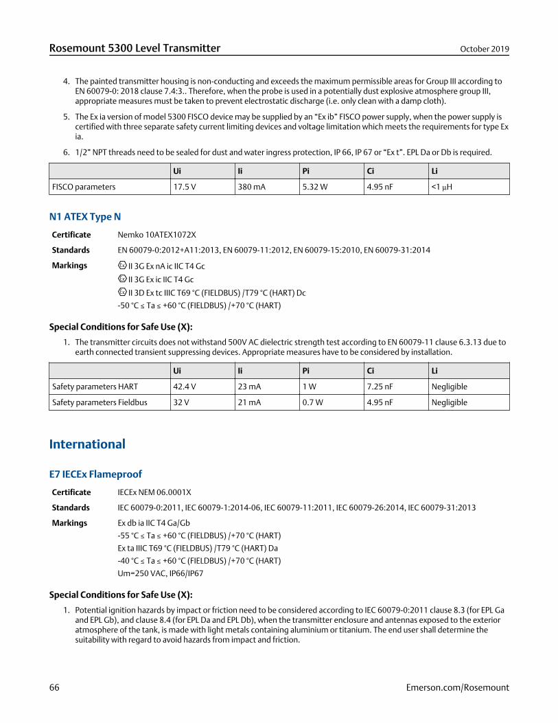
4. The painted transmitter housing is non-conducting and exceeds the maximum permissible areas for Group III according toEN 60079-0: 2018 clause 7.4:3.. Therefore, when the probe is used in a potentially dust explosive atmosphere group III,appropriate measures must be taken to prevent electrostatic discharge (i.e. only clean with a damp cloth).
5. The Ex ia version of model 5300 FISCO device may be supplied by an “Ex ib” FISCO power supply, when the power supply iscertified with three separate safety current limiting devices and voltage limitation which meets the requirements for type Exia.
6. 1/2” NPT threads need to be sealed for dust and water ingress protection, IP 66, IP 67 or “Ex t”. EPL Da or Db is required.
Ui Ii Pi Ci Li
FISCO parameters 17.5 V 380 mA 5.32 W 4.95 nF <1 µH
N1 ATEX Type N
Certificate Nemko 10ATEX1072X
Standards EN 60079-0:2012+A11:2013, EN 60079-11:2012, EN 60079-15:2010, EN 60079-31:2014
Markings II 3G Ex nA ic IIC T4 Gc
II 3G Ex ic IIC T4 Gc
II 3D Ex tc IIIC T69 °C (FIELDBUS) /T79 °C (HART) Dc
-50 °C ≤ Ta ≤ +60 °C (FIELDBUS) /+70 °C (HART)
Special Conditions for Safe Use (X):
1. The transmitter circuits does not withstand 500V AC dielectric strength test according to EN 60079-11 clause 6.3.13 due toearth connected transient suppressing devices. Appropriate measures have to be considered by installation.
Ui Ii Pi Ci Li
Safety parameters HART 42.4 V 23 mA 1 W 7.25 nF Negligible
Safety parameters Fieldbus 32 V 21 mA 0.7 W 4.95 nF Negligible
International
E7 IECEx Flameproof
Certificate IECEx NEM 06.0001X
Standards IEC 60079-0:2011, IEC 60079-1:2014-06, IEC 60079-11:2011, IEC 60079-26:2014, IEC 60079-31:2013
Markings Ex db ia IIC T4 Ga/Gb
-55 °C ≤ Ta ≤ +60 °C (FIELDBUS) /+70 °C (HART)
Ex ta IIIC T69 °C (FIELDBUS) /T79 °C (HART) Da
-40 °C ≤ Ta ≤ +60 °C (FIELDBUS) /+70 °C (HART)
Um=250 VAC, IP66/IP67
Special Conditions for Safe Use (X):
1. Potential ignition hazards by impact or friction need to be considered according to IEC 60079-0:2011 clause 8.3 (for EPL Gaand EPL Gb), and clause 8.4 (for EPL Da and EPL Db), when the transmitter enclosure and antennas exposed to the exterioratmosphere of the tank, is made with light metals containing aluminium or titanium. The end user shall determine thesuitability with regard to avoid hazards from impact and friction.
Rosemount 5300 Level Transmitter October 2019
66 Emerson.com/Rosemount
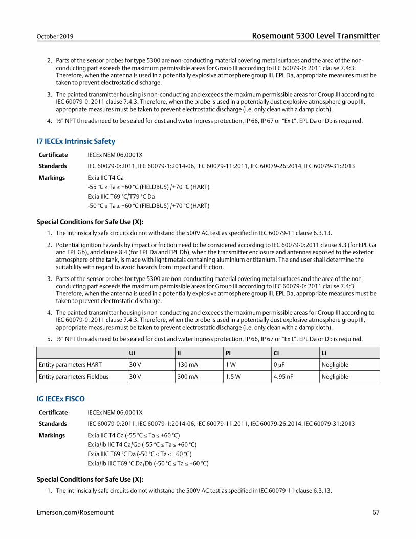
2. Parts of the sensor probes for type 5300 are non-conducting material covering metal surfaces and the area of the non-conducting part exceeds the maximum permissible areas for Group III according to IEC 60079-0: 2011 clause 7.4:3.Therefore, when the antenna is used in a potentially explosive atmosphere group III, EPL Da, appropriate measures must betaken to prevent electrostatic discharge.
3. The painted transmitter housing is non-conducting and exceeds the maximum permissible areas for Group III according toIEC 60079-0: 2011 clause 7.4:3. Therefore, when the probe is used in a potentially dust explosive atmosphere group III,appropriate measures must be taken to prevent electrostatic discharge (i.e. only clean with a damp cloth).
4. ½” NPT threads need to be sealed for dust and water ingress protection, IP 66, IP 67 or “Ex t”. EPL Da or Db is required.
I7 IECEx Intrinsic Safety
Certificate IECEx NEM 06.0001X
Standards IEC 60079-0:2011, IEC 60079-1:2014-06, IEC 60079-11:2011, IEC 60079-26:2014, IEC 60079-31:2013
Markings Ex ia IIC T4 Ga
-55 °C ≤ Ta ≤ +60 °C (FIELDBUS) /+70 °C (HART)
Ex ia IIIC T69 °C/T79 °C Da
-50 °C ≤ Ta ≤ +60 °C (FIELDBUS) /+70 °C (HART)
Special Conditions for Safe Use (X):
1. The intrinsically safe circuits do not withstand the 500V AC test as specified in IEC 60079-11 clause 6.3.13.
2. Potential ignition hazards by impact or friction need to be considered according to IEC 60079-0:2011 clause 8.3 (for EPL Gaand EPL Gb), and clause 8.4 (for EPL Da and EPL Db), when the transmitter enclosure and antennas exposed to the exterioratmosphere of the tank, is made with light metals containing aluminium or titanium. The end user shall determine thesuitability with regard to avoid hazards from impact and friction.
3. Parts of the sensor probes for type 5300 are non-conducting material covering metal surfaces and the area of the non-conducting part exceeds the maximum permissible areas for Group III according to IEC 60079-0: 2011 clause 7.4:3Therefore, when the antenna is used in a potentially explosive atmosphere group III, EPL Da, appropriate measures must betaken to prevent electrostatic discharge.
4. The painted transmitter housing is non-conducting and exceeds the maximum permissible areas for Group III according toIEC 60079-0: 2011 clause 7.4:3. Therefore, when the probe is used in a potentially dust explosive atmosphere group III,appropriate measures must be taken to prevent electrostatic discharge (i.e. only clean with a damp cloth).
5. ½” NPT threads need to be sealed for dust and water ingress protection, IP 66, IP 67 or “Ex t”. EPL Da or Db is required.
Ui Ii Pi Ci Li
Entity parameters HART 30 V 130 mA 1 W 0 µF Negligible
Entity parameters Fieldbus 30 V 300 mA 1.5 W 4.95 nF Negligible
IG IECEx FISCO
Certificate IECEx NEM 06.0001X
Standards IEC 60079-0:2011, IEC 60079-1:2014-06, IEC 60079-11:2011, IEC 60079-26:2014, IEC 60079-31:2013
Markings Ex ia IIC T4 Ga (-55 °C ≤ Ta ≤ +60 °C)
Ex ia/ib IIC T4 Ga/Gb (-55 °C ≤ Ta ≤ +60 °C)
Ex ia IIIC T69 °C Da (-50 °C ≤ Ta ≤ +60 °C)
Ex ia/ib IIIC T69 °C Da/Db (-50 °C ≤ Ta ≤ +60 °C)
Special Conditions for Safe Use (X):
1. The intrinsically safe circuits do not withstand the 500V AC test as specified in IEC 60079-11 clause 6.3.13.
October 2019 Rosemount 5300 Level Transmitter
Emerson.com/Rosemount 67
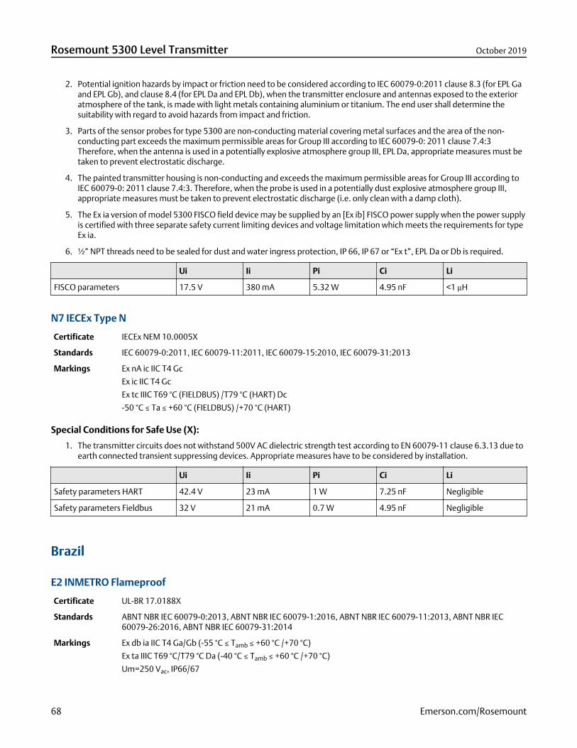
2. Potential ignition hazards by impact or friction need to be considered according to IEC 60079-0:2011 clause 8.3 (for EPL Gaand EPL Gb), and clause 8.4 (for EPL Da and EPL Db), when the transmitter enclosure and antennas exposed to the exterioratmosphere of the tank, is made with light metals containing aluminium or titanium. The end user shall determine thesuitability with regard to avoid hazards from impact and friction.
3. Parts of the sensor probes for type 5300 are non-conducting material covering metal surfaces and the area of the non-conducting part exceeds the maximum permissible areas for Group III according to IEC 60079-0: 2011 clause 7.4:3Therefore, when the antenna is used in a potentially explosive atmosphere group III, EPL Da, appropriate measures must betaken to prevent electrostatic discharge.
4. The painted transmitter housing is non-conducting and exceeds the maximum permissible areas for Group III according toIEC 60079-0: 2011 clause 7.4:3. Therefore, when the probe is used in a potentially dust explosive atmosphere group III,appropriate measures must be taken to prevent electrostatic discharge (i.e. only clean with a damp cloth).
5. The Ex ia version of model 5300 FISCO field device may be supplied by an [Ex ib] FISCO power supply when the power supplyis certified with three separate safety current limiting devices and voltage limitation which meets the requirements for typeEx ia.
6. ½” NPT threads need to be sealed for dust and water ingress protection, IP 66, IP 67 or “Ex t”, EPL Da or Db is required.
Ui Ii Pi Ci Li
FISCO parameters 17.5 V 380 mA 5.32 W 4.95 nF <1 µH
N7 IECEx Type N
Certificate IECEx NEM 10.0005X
Standards IEC 60079-0:2011, IEC 60079-11:2011, IEC 60079-15:2010, IEC 60079-31:2013
Markings Ex nA ic IIC T4 Gc
Ex ic IIC T4 Gc
Ex tc IIIC T69 °C (FIELDBUS) /T79 °C (HART) Dc
-50 °C ≤ Ta ≤ +60 °C (FIELDBUS) /+70 °C (HART)
Special Conditions for Safe Use (X):
1. The transmitter circuits does not withstand 500V AC dielectric strength test according to EN 60079-11 clause 6.3.13 due toearth connected transient suppressing devices. Appropriate measures have to be considered by installation.
Ui Ii Pi Ci Li
Safety parameters HART 42.4 V 23 mA 1 W 7.25 nF Negligible
Safety parameters Fieldbus 32 V 21 mA 0.7 W 4.95 nF Negligible
Brazil
E2 INMETRO Flameproof
Certificate UL-BR 17.0188X
Standards ABNT NBR IEC 60079-0:2013, ABNT NBR IEC 60079-1:2016, ABNT NBR IEC 60079-11:2013, ABNT NBR IEC60079-26:2016, ABNT NBR IEC 60079-31:2014
Markings Ex db ia IIC T4 Ga/Gb (-55 °C ≤ Tamb ≤ +60 °C /+70 °C)
Ex ta IIIC T69 °C/T79 °C Da (-40 °C ≤ Tamb ≤ +60 °C /+70 °C)
Um=250 Vac, IP66/67
Rosemount 5300 Level Transmitter October 2019
68 Emerson.com/Rosemount
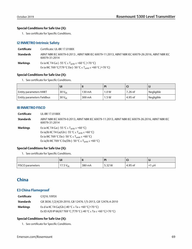
Special Conditions for Safe Use (X):
1. See certificate for Specific Conditions.
I2 INMETRO Intrinsic Safety
Certificate Certificate: UL-BR 17.0188X
Standards ABNT NBR IEC 60079-0:2013 , ABNT NBR IEC 60079-11:2013, ABNT NBR IEC 60079-26:2016, ABNT NBR IEC60079-31:2014
Markings Ex ia IIC T4 Ga (- 55 °C ≤ Tamb ≤ +60 °C /+70 °C)
Ex ia IIIC T69 °C/T79 °C Da (- 50 °C ≤ Tamb ≤ +60 °C /+70 °C)
Special Conditions for Safe Use (X):
1. See certificate for Specific Conditions.
Ui Ii Pi Ci Li
Entity parameters HART 30 Vdc 130 mA 1.0 W 7.26 nF Negligible
Entity parameters Fieldbus 30 Vdc 300 mA 1.5 W 4.95 nF Negligible
IB INMETRO FISCO
Certificate UL-BR 17.0188X
Standards ABNT NBR IEC 60079-0:2013, ABNT NBR IEC 60079-11:2013, ABNT NBR IEC 60079-26:2016, ABNT NBR IEC60079-31:2014
Markings Ex ia IIC T4 Ga (- 55 °C ≤ Tamb ≤ +60 °C)
Ex ia/ib IIC T4 Ga/Gb (- 55 °C ≤ Tamb ≤ +60 °C)
Ex ia IIIC T69 °C Da (- 50 °C ≤ Tamb ≤ +60 °C)
Ex ia/ib IIIC T69 °C Da/Db (- 50 °C ≤ Tamb ≤ +60 °C)
Special Conditions for Safe Use (X):
1. See certificate for Specific Conditions.
Ui Ii Pi Ci Li
FISCO parameters 17.5 Vdc 380 mA 5.32 W 4.95 nF <1 µH
China
E3 China Flameproof
Certificate GYJ16.1095X
Standards GB 3836.1/2/4/20-2010, GB 12476.1/5-2013, GB 12476.4-2010
Markings Ex d ia IIC T4 Ga/Gb (-40 °C ≤ Ta ≤ +60 °C/+70 °C)
Ex tD A20 IP 66/67 T69 °C /T79 °C (-40 °C ≤ Ta ≤ +60 °C/+70 °C)
Special Conditions for Safe Use (X):
1. See certificate for Specific Conditions.
October 2019 Rosemount 5300 Level Transmitter
Emerson.com/Rosemount 69
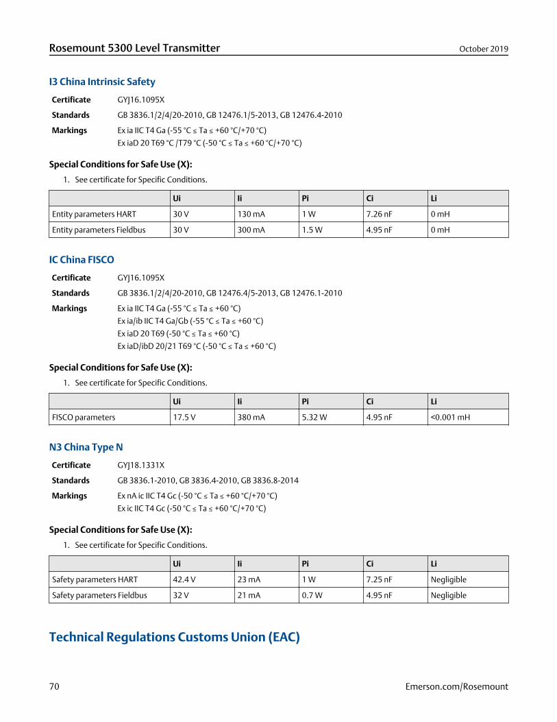
I3 China Intrinsic Safety
Certificate GYJ16.1095X
Standards GB 3836.1/2/4/20-2010, GB 12476.1/5-2013, GB 12476.4-2010
Markings Ex ia IIC T4 Ga (-55 °C ≤ Ta ≤ +60 °C/+70 °C)
Ex iaD 20 T69 °C /T79 °C (-50 °C ≤ Ta ≤ +60 °C/+70 °C)
Special Conditions for Safe Use (X):
1. See certificate for Specific Conditions.
Ui Ii Pi Ci Li
Entity parameters HART 30 V 130 mA 1 W 7.26 nF 0 mH
Entity parameters Fieldbus 30 V 300 mA 1.5 W 4.95 nF 0 mH
IC China FISCO
Certificate GYJ16.1095X
Standards GB 3836.1/2/4/20-2010, GB 12476.4/5-2013, GB 12476.1-2010
Markings Ex ia IIC T4 Ga (-55 °C ≤ Ta ≤ +60 °C)
Ex ia/ib IIC T4 Ga/Gb (-55 °C ≤ Ta ≤ +60 °C)
Ex iaD 20 T69 (-50 °C ≤ Ta ≤ +60 °C)
Ex iaD/ibD 20/21 T69 °C (-50 °C ≤ Ta ≤ +60 °C)
Special Conditions for Safe Use (X):
1. See certificate for Specific Conditions.
Ui Ii Pi Ci Li
FISCO parameters 17.5 V 380 mA 5.32 W 4.95 nF <0.001 mH
N3 China Type N
Certificate GYJ18.1331X
Standards GB 3836.1-2010, GB 3836.4-2010, GB 3836.8-2014
Markings Ex nA ic IIC T4 Gc (-50 °C ≤ Ta ≤ +60 °C/+70 °C)
Ex ic IIC T4 Gc (-50 °C ≤ Ta ≤ +60 °C/+70 °C)
Special Conditions for Safe Use (X):
1. See certificate for Specific Conditions.
Ui Ii Pi Ci Li
Safety parameters HART 42.4 V 23 mA 1 W 7.25 nF Negligible
Safety parameters Fieldbus 32 V 21 mA 0.7 W 4.95 nF Negligible
Technical Regulations Customs Union (EAC)
Rosemount 5300 Level Transmitter October 2019
70 Emerson.com/Rosemount
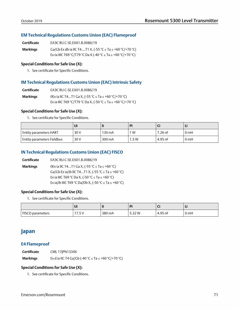
EM Technical Regulations Customs Union (EAC) Flameproof
Certificate ЕАЭС RU C-SE.EX01.B.0086/19
Markings Ga/Gb Ex db ia IIC T4….T1 X, (-55 °C ≤ Ta ≤ +60 °C/+70 °C)
Ex ta IIIC T69 °C/T79 °C Da X (-40 °C ≤ Ta ≤ +60 °C/+70 °C)
Special Conditions for Safe Use (X):
1. See certificate for Specific Conditions.
IM Technical Regulations Customs Union (EAC) Intrinsic Safety
Certificate ЕАЭС RU C-SE.EX01.B.0086/19
Markings 0Ex ia IIC T4...T1 Ga X, (-55 °C ≤ Ta ≤ +60 °C/+70 °C)
Ex ia IIIC T69 °C/T79 °C Da X, (-50 °C ≤ Ta ≤ +60 °C/+70 °C)
Special Conditions for Safe Use (X):
1. See certificate for Specific Conditions.
Ui Ii Pi Ci Li
Entity parameters HART 30 V 130 mA 1 W 7.26 nF 0 mH
Entity parameters Fieldbus 30 V 300 mA 1.5 W 4.95 nF 0 mH
IN Technical Regulations Customs Union (EAC) FISCO
Certificate ЕАЭС RU C-SE.EX01.B.0086/19
Markings 0Ex ia IIC T4...T1 Ga X, (-55 °C ≤ Ta ≤ +60 °C)
Ga/Gb Ex ia/ib IIC T4…T1 X, (-55 °C ≤ Ta ≤ +60 °C)
Ex ia IIIC T69 °C Da X, (-50 °C ≤ Ta ≤ +60 °C)
Ex ia/ib IIIC T69 °C Da/Db X, (-50 °C ≤ Ta ≤ +60 °C)
Special Conditions for Safe Use (X):
1. See certificate for Specific Conditions.
Ui Ii Pi Ci Li
FISCO parameters 17.5 V 380 mA 5.32 W 4.95 nF 0 mH
Japan
E4 Flameproof
Certificate CML 17JPN1334X
Markings Ex d ia IIC T4 Ga/Gb (-40 °C ≤ Ta ≤ +60 °C/+70 °C)
Special Conditions for Safe Use (X):
1. See certificate for Specific Conditions.
October 2019 Rosemount 5300 Level Transmitter
Emerson.com/Rosemount 71

Republic of Korea
EP Flameproof HART
Certificate KTL 15-KB4BO-0297X, 13-KB4BO-0019X
Markings Ex d ia IIC T4 Ga/Gb
Special Conditions for Safe Use (X):
1. See certificate for Specific Conditions.
EP Flameproof Fieldbus
Certificate KTL 12-KB4BO-0179X
Markings Ex d ia IIC T4
Special Conditions for Safe Use (X):
1. See certificate for Specific Conditions.
India
Flameproof, Intrinsically safe
Certificate P392482/1
Markings Ex db ia IIC T4 Ga /Gb
Ex ia IIC T4 Ga
Special Conditions for Safe Use (X):
1. See certificate for Specific Conditions.
Ukraine
Flameproof, Intrinsically Safe
Certificate UA.TR.047.C.0352-13
Markings 0 Ex ia IIC T4 X,
1 Ex d ia IIC T4 X
Special Conditions for Safe Use (X):
1. See certificate for Specific Conditions.
Rosemount 5300 Level Transmitter October 2019
72 Emerson.com/Rosemount
Uzbekistan
Safety (import)
Certificate UZ.SMT.01.342.2017121
Combinations
KA Combination of E1, E5 and E6
KB Combination of E1, E5 and E7
KC Combination of E1, E6 and E7
KD Combination of E5, E6 and E7
KE Combination of I1, I5 and I6
KF Combination of I1, I5 and I7
KG Combination of I1, I6 and I7
KH Combination of I5, I6 and I7
KI Combination of IA, IE and IF
KJ Combination of IA, IE and IG
KK Combination of IA, IF and IG
KL Combination of IE, IF and IG
Additional certifications
SBS American Bureau of Shipping (ABS) Type Approval
Certificate 15-LD1340199-1-PDA
Intended Use For use on ABS Classed Vessels and Offshore Facilities in accordance with ABS rules and InternationalStandards.
NoteHousing material A, Aluminum, is not to be used on open decks.
SBV Bureau Veritas (BV) Type Approval
Certificate 22378_B3 BV
Requirements Bureau Veritas rules for classification of steel ships. EC Code: 41SB
Application Class Notations: AUT-UMS, AUT-CCS, AUT-PORT and AUT-IMS.
NoteHousing material A, Aluminum, is not to be used on open decks.
SDN Det Norske Veritas Germanischer Lloyd (DNV GL) Type Approval
Certificate TAA000020G
October 2019 Rosemount 5300 Level Transmitter
Emerson.com/Rosemount 73
Intended Use DNV GL rules for classification – Ships, offshore units, and high speed and light craft
Table 35: Application
Location classes
Temperature D
Humidity B
Vibration A
EMC B
Enclosure C
NoteHousing material A, Aluminum, is not to be used on open decks.
SKR Korean Register (KR) Type Approval
Certificate CPH05152-AE001
Requirements Pt. 6, Ch. 2, Art. 301 of the Rules for Classification of Steel Ships.
NoteHousing material A, Aluminum, is not to be used on open decks.
SLL Lloyds Register (LR) Type Approval
Certificate 15/20053
Application Marine applications for use in environmental categories ENV1, ENV2, ENV3 and ENV5.
NoteHousing material A, Aluminum, is not to be used on open decks.
U1 Overfill prevention
Certificate Z-65.16-476
Application TÜV tested and approved by DIBt for overfill prevention according to the German WHG regulations.
J8 EN Boiler (European Boiler Approval in accordance with EN 12952-11 and EN 12953-9)
NoteSuitable for use as a level sensor part of a limiting device in accordance with EN 12952-11 and EN 12953-9.
QT Safety-certified to IEC 61508:2010 with certificate of FMEDA data
Certificate exida ROS 13-06-005 C001 R2.1
Suitable for intended useCompliant with NAMUR NE 95, version 22.01.2013 “Basic Principles of Homologation”
Rosemount 5300 Level Transmitter October 2019
74 Emerson.com/Rosemount

Pattern Approval
GOST Belarus
Certificate No. 10263
GOST Kazakhstan
Certificate No. 15466
GOST Russia
Certificate SE.C.29.010.A No.51062/1
GOST Uzbekistan
Certificate 02.7101
China Pattern Approval
Certificate CPA 2012-L135
Conduit plugs and adapters
IECEx Flameproof and Increased Safety
Certificate IECEX UL 18.0016X
Standards IEC60079-0:2011, IEC60079-1:2014, IEC60079-7:2015, IEC60079-31:2014
Markings Ex db eb IIC Gb; Ex ta IIIC Da
ATEX Flameproof and Increased Safety
Certificate DEMKO 18 ATEX 1986X
Standards EN 60079-0:2012+A11:2013, EN 60079-1:2014, EN 60079-7:2015, EN 60079-31:2014
Markings II 2 G Ex db eb IIC Gb
II 1 D Ex ta IIIC Da
Table 36: Conduit Plug Thread Sizes
Thread Identification mark
M20x1.5-6g M20
½ - 14 NPT ½ NPT
October 2019 Rosemount 5300 Level Transmitter
Emerson.com/Rosemount 75
Table 37: Thread Adapter Thread Sizes
Male thread Identification mark
M20 x 1.5 – 6g M20
½- 14 NPT ½ - 14 NPT
Female thread Identification mark
M20 x 1.5 – 6H M20
½ - 14 NPT ½ - 14 NPT
Specific Conditions for Safe Use (X):
1. The Blanking Elements shall not be used with an adapter.
2. Only one adapter shall be used with any single cable entry on the associated equipment.
3. It is the end user’s responsibility to ensure that the ingress protection rating is maintained at the interface of the equipmentand the blanking element/adapter.
4. Suitability of the temperature of the devices is to be determined during end-use with suitably rated equipment.
Rosemount 5300 Level Transmitter October 2019
76 Emerson.com/Rosemount
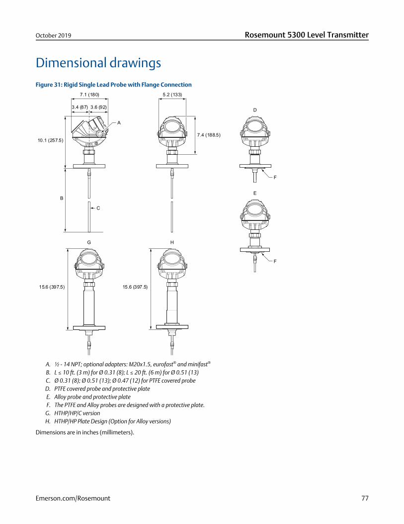
Dimensional drawingsFigure 31: Rigid Single Lead Probe with Flange Connection
7.1 (180)
B
3.4 (87) 3.6 (92)
10.1 (257.5)
C
15.6 (397.5)
5.2 (133)
G
D
F
F
7.4 (188.5)
H
15.6 (397.5)
E
A
A. ½ - 14 NPT; optional adapters: M20x1.5, eurofast® and minifast®
B. L ≤ 10 ft. (3 m) for Ø 0.31 (8); L ≤ 20 ft. (6 m) for Ø 0.51 (13)C. Ø 0.31 (8); Ø 0.51 (13); Ø 0.47 (12) for PTFE covered probeD. PTFE covered probe and protective plateE. Alloy probe and protective plateF. The PTFE and Alloy probes are designed with a protective plate.
G. HTHP/HP/C versionH. HTHP/HP Plate Design (Option for Alloy versions)
Dimensions are in inches (millimeters).
October 2019 Rosemount 5300 Level Transmitter
Emerson.com/Rosemount 77
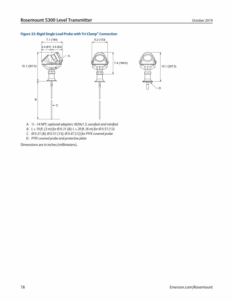
Figure 32: Rigid Single Lead Probe with Tri-Clamp® Connection
5.2 (133)7.1 (180)
B
3.4 (87) 3.6 (92)
7.4 (188.5)10.1 (257.5)10.1 (257.5)
C
D
A
A. ½ - 14 NPT; optional adapters: M20x1.5, eurofast and minifastB. L ≤ 10 ft. (3 m) for Ø 0.31 (8); L ≤ 20 ft. (6 m) for Ø 0.51 (13)C. Ø 0.31 (8); Ø 0.51 (13); Ø 0.47 (12) for PTFE covered probeD. PTFE covered probe and protective plate
Dimensions are in inches (millimeters).
Rosemount 5300 Level Transmitter October 2019
78 Emerson.com/Rosemount
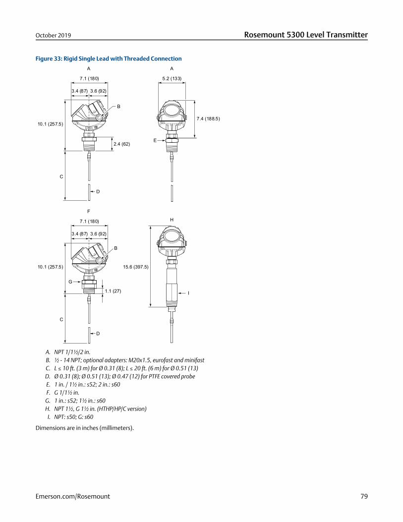
Figure 33: Rigid Single Lead with Threaded Connection
5.2 (133)7.1 (180)
E
G
I
2.4 (62)
C
3.4 (87) 3.6 (92)
7.4 (188.5)10.1 (257.5)
D
D
A
7.1 (180)
B
C
3.4 (87) 3.6 (92)
10.1 (257.5) 15.6 (397.5)
FH
A
1.1 (27)
B
A. NPT 1/1½/2 in.B. ½ - 14 NPT; optional adapters: M20x1.5, eurofast and minifastC. L ≤ 10 ft. (3 m) for Ø 0.31 (8); L ≤ 20 ft. (6 m) for Ø 0.51 (13)D. Ø 0.31 (8); Ø 0.51 (13); Ø 0.47 (12) for PTFE covered probeE. 1 in. / 1½ in.: s52; 2 in.: s60F. G 1/1½ in.
G. 1 in.: s52; 1½ in.: s60H. NPT 1½, G 1½ in. (HTHP/HP/C version)
I. NPT: s50; G: s60
Dimensions are in inches (millimeters).
October 2019 Rosemount 5300 Level Transmitter
Emerson.com/Rosemount 79
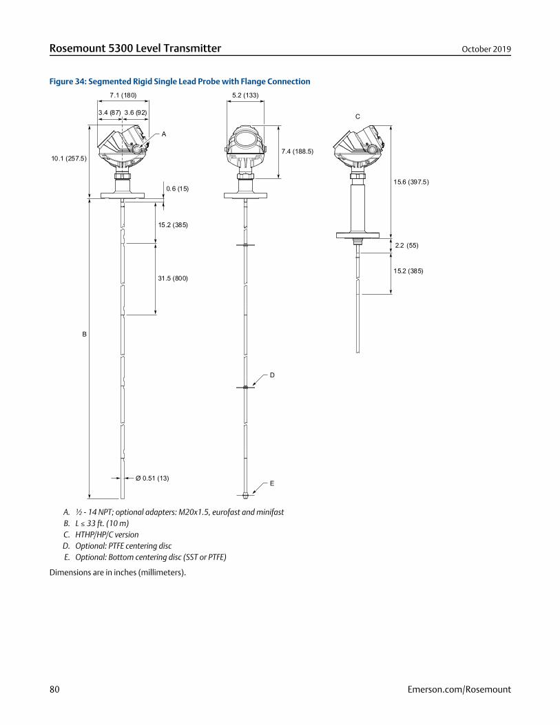
Figure 34: Segmented Rigid Single Lead Probe with Flange Connection
15.2 (385)
31.5 (800)
0.6 (15)
7.1 (180) 5.2 (133)
7.4 (188.5)
3.4 (87) 3.6 (92)
10.1 (257.5)
B
C
D
Ø 0.51 (13)E
15.6 (397.5)
2.2 (55)
15.2 (385)
A
A. ½ - 14 NPT; optional adapters: M20x1.5, eurofast and minifastB. L ≤ 33 ft. (10 m)C. HTHP/HP/C versionD. Optional: PTFE centering discE. Optional: Bottom centering disc (SST or PTFE)
Dimensions are in inches (millimeters).
Rosemount 5300 Level Transmitter October 2019
80 Emerson.com/Rosemount
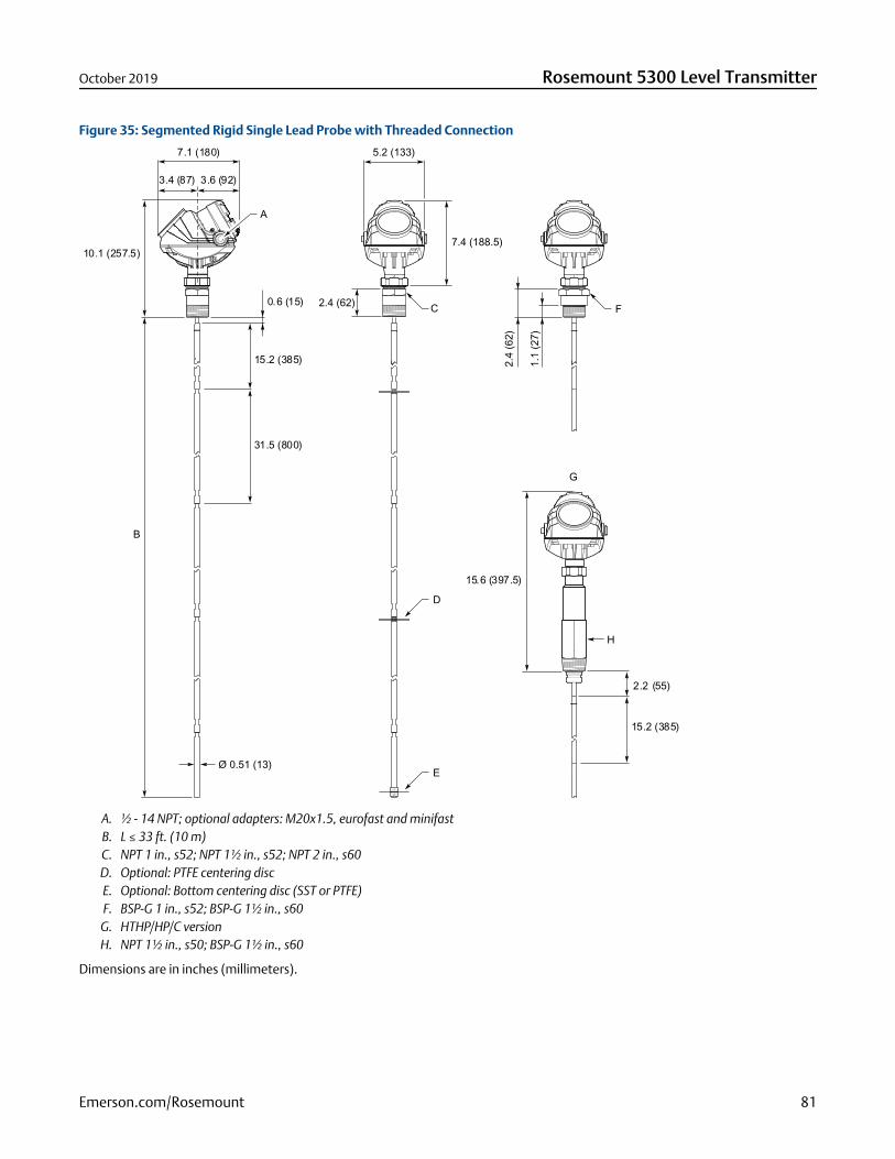
Figure 35: Segmented Rigid Single Lead Probe with Threaded Connection
2.4 (62)
15.2 (385)
31.5 (800)
0.6 (15)
7.1 (180) 5.2 (133)
C F
H
7.4 (188.5)
2.4
(62)
1.1
(27)
3.4 (87) 3.6 (92)
10.1 (257.5)
B
G
D
EØ 0.51 (13)
2.2 (55)
15.2 (385)
15.6 (397.5)
A
A. ½ - 14 NPT; optional adapters: M20x1.5, eurofast and minifastB. L ≤ 33 ft. (10 m)C. NPT 1 in., s52; NPT 1½ in., s52; NPT 2 in., s60D. Optional: PTFE centering discE. Optional: Bottom centering disc (SST or PTFE)F. BSP-G 1 in., s52; BSP-G 1½ in., s60G. HTHP/HP/C versionH. NPT 1½ in., s50; BSP-G 1½ in., s60
Dimensions are in inches (millimeters).
October 2019 Rosemount 5300 Level Transmitter
Emerson.com/Rosemount 81
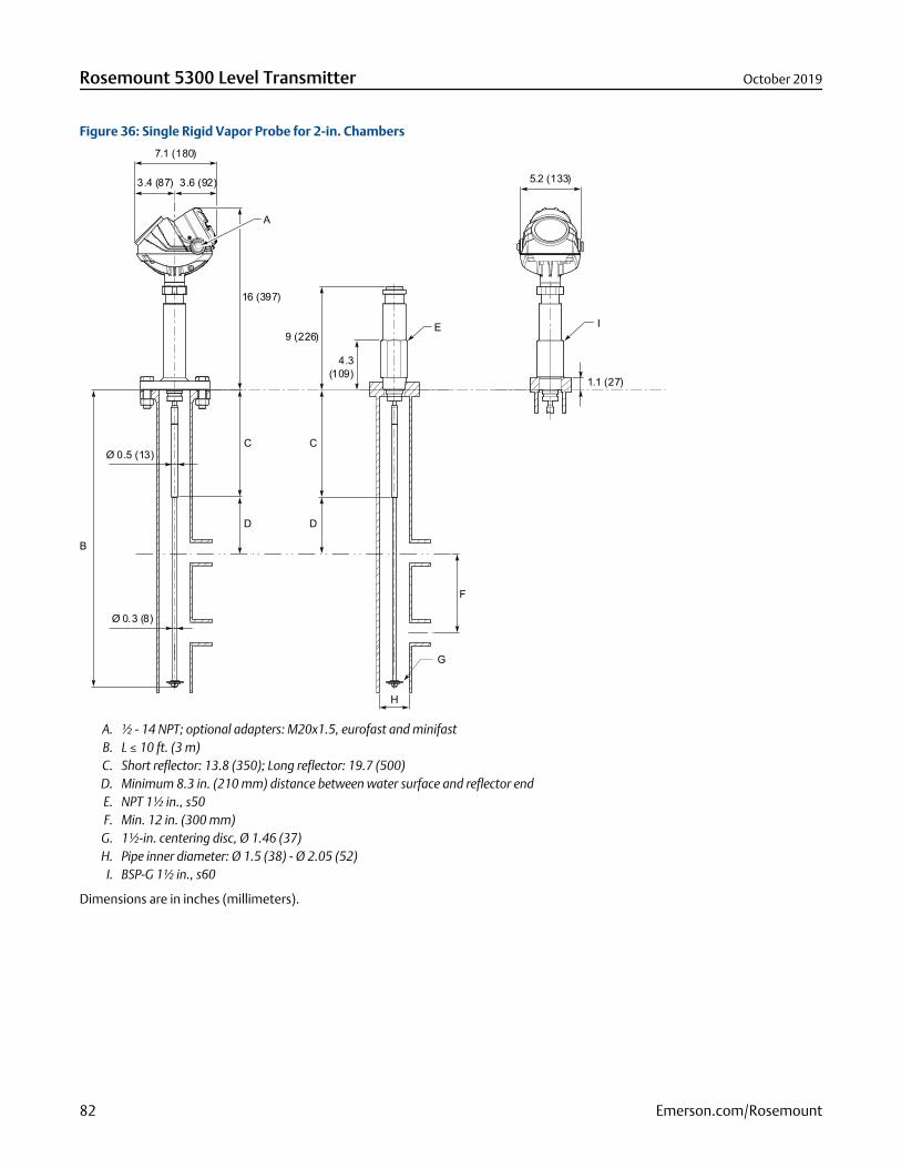
Figure 36: Single Rigid Vapor Probe for 2-in. Chambers
7.1 (180)
3.4 (87) 3.6 (92)
16 (397)
A
C C
D D
4.3(109)
9 (226)E I
F
G
H
Ø 0.3 (8)
5.2 (133)
Ø 0.5 (13)
B
1.1 (27)
A. ½ - 14 NPT; optional adapters: M20x1.5, eurofast and minifastB. L ≤ 10 ft. (3 m)C. Short reflector: 13.8 (350); Long reflector: 19.7 (500)D. Minimum 8.3 in. (210 mm) distance between water surface and reflector endE. NPT 1½ in., s50F. Min. 12 in. (300 mm)
G. 1½-in. centering disc, Ø 1.46 (37)H. Pipe inner diameter: Ø 1.5 (38) - Ø 2.05 (52)
I. BSP-G 1½ in., s60
Dimensions are in inches (millimeters).
Rosemount 5300 Level Transmitter October 2019
82 Emerson.com/Rosemount
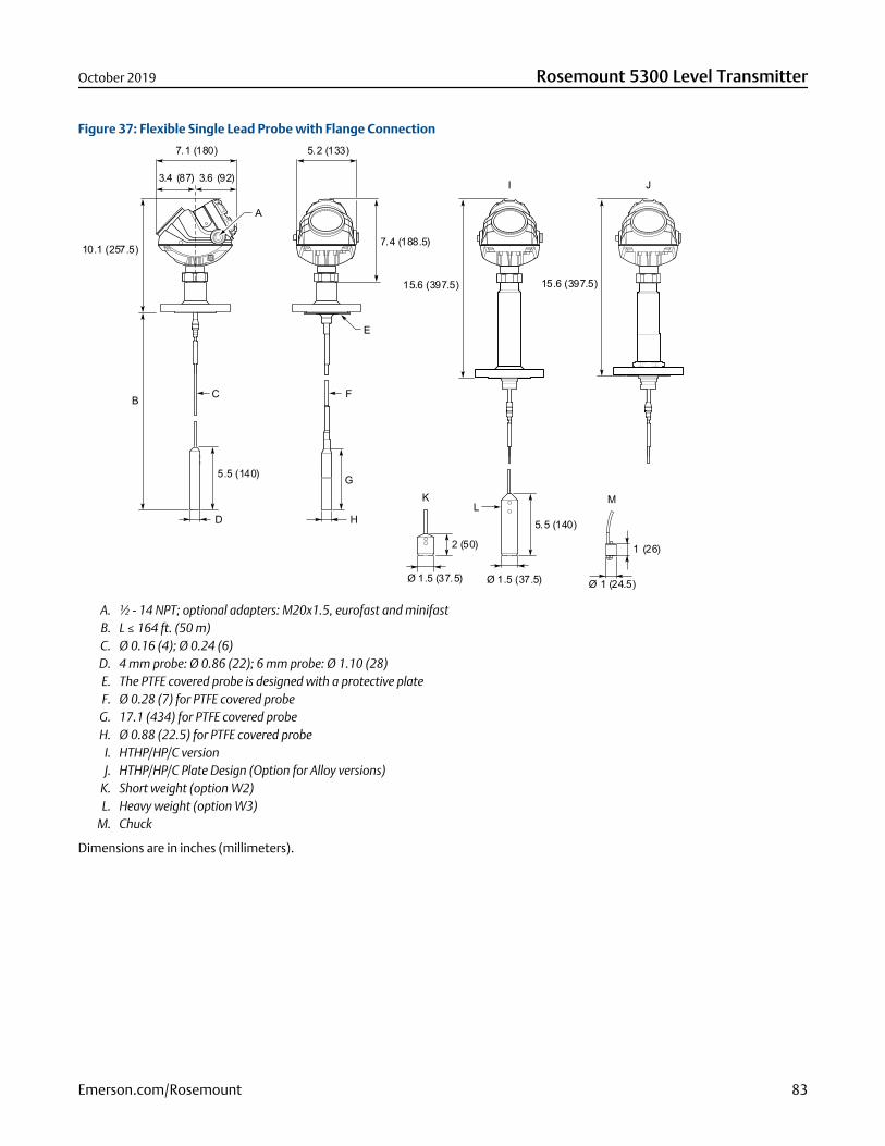
Figure 37: Flexible Single Lead Probe with Flange Connection
5.2 (133)7.1 (180)
3.4 (87) 3.6 (92)
B
7.4 (188.5)10.1 (257.5)
5.5 (140)
D
E
F
15.6 (397.5) 15.6 (397.5)
C
H
G
I J
LK
2 (50)
Ø 1.5 (37.5)
5.5 (140)
Ø 1.5 (37.5)
M
Ø 1 (24.5)
1 (26)
A
A. ½ - 14 NPT; optional adapters: M20x1.5, eurofast and minifastB. L ≤ 164 ft. (50 m)C. Ø 0.16 (4); Ø 0.24 (6)D. 4 mm probe: Ø 0.86 (22); 6 mm probe: Ø 1.10 (28)E. The PTFE covered probe is designed with a protective plateF. Ø 0.28 (7) for PTFE covered probe
G. 17.1 (434) for PTFE covered probeH. Ø 0.88 (22.5) for PTFE covered probe
I. HTHP/HP/C versionJ. HTHP/HP/C Plate Design (Option for Alloy versions)
K. Short weight (option W2)L. Heavy weight (option W3)
M. Chuck
Dimensions are in inches (millimeters).
October 2019 Rosemount 5300 Level Transmitter
Emerson.com/Rosemount 83
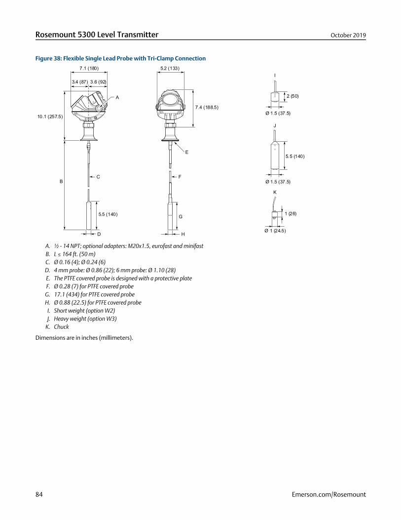
Figure 38: Flexible Single Lead Probe with Tri-Clamp Connection
7.1 (180)
B
10.1 (257.5)
E
F
5.2 (133)
7.4 (188.5)
C
D H
5.5 (140)
I
2 (50)
J
Ø 1.5 (37.5)
5.5 (140)
Ø 1.5 (37.5)
3.4 (87) 3.6 (92)
G
K
Ø 1 (24.5)
1 (26)
A
A. ½ - 14 NPT; optional adapters: M20x1.5, eurofast and minifastB. L ≤ 164 ft. (50 m)C. Ø 0.16 (4); Ø 0.24 (6)D. 4 mm probe: Ø 0.86 (22); 6 mm probe: Ø 1.10 (28)E. The PTFE covered probe is designed with a protective plateF. Ø 0.28 (7) for PTFE covered probe
G. 17.1 (434) for PTFE covered probeH. Ø 0.88 (22.5) for PTFE covered probe
I. Short weight (option W2)J. Heavy weight (option W3)
K. Chuck
Dimensions are in inches (millimeters).
Rosemount 5300 Level Transmitter October 2019
84 Emerson.com/Rosemount
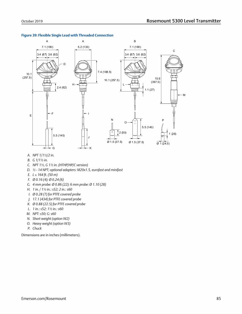
Figure 39: Flexible Single Lead with Threaded Connection
5.2 (133)7.1 (180)
3.4 (87) 3.6 (92)
E
7.4 (188.5)10.1
(257.5)
5.5 (140)
G
D
H
I
L
O
M
F
K
J
2.4 (62)1.1 (27)
15.6(397.5)
N
2 (50)
Ø 1.5 (37.5)
5.5 (140)
Ø 1.5 (37.5)
P
Ø 1 (24.5)
1 (26)
A
7.1 (180)
3.4 (87) 3.6 (92)
10.1 (257.5)
B
C
A
A. NPT 1/1½/2 in.B. G 1/1½ in.C. NPT 1½, G 1½ in. (HTHP/HP/C version)D. ½ - 14 NPT; optional adapters: M20x1.5, eurofast and minifastE. L ≤ 164 ft. (50 m)F. Ø 0.16 (4); Ø 0.24 (6)
G. 4 mm probe: Ø 0.86 (22); 6 mm probe: Ø 1.10 (28)H. 1 in. / 1½ in.: s52; 2 in.: s60
I. Ø 0.28 (7) for PTFE covered probeJ. 17.1 (434) for PTFE covered probe
K. Ø 0.88 (22.5) for PTFE covered probeL. 1 in.: s52; 1½ in.: s60
M. NPT: s50; G: s60N. Short weight (option W2)O. Heavy weight (option W3)P. Chuck
Dimensions are in inches (millimeters).
October 2019 Rosemount 5300 Level Transmitter
Emerson.com/Rosemount 85
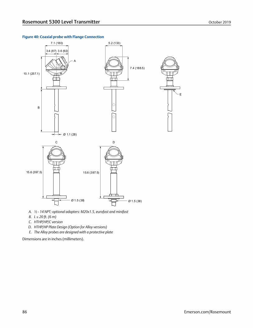
Figure 40: Coaxial probe with Flange Connection
B
10.1 (257.1)
5.2 (133)7.1 (180)
3.4 (87) 3.6 (92)
Ø 1.1 (28)
7.4 (188.5)
15.6 (397.5) 15.6 (397.5)
Ø 1.5 (38) Ø 1.5 (38)
C D
E
A
A. ½ - 14 NPT; optional adapters: M20x1.5, eurofast and minifastB. L ≤ 20 ft. (6 m)C. HTHP/HP/C versionD. HTHP/HP Plate Design (Option for Alloy versions)E. The Alloy probes are designed with a protective plate
Dimensions are in inches (millimeters).
Rosemount 5300 Level Transmitter October 2019
86 Emerson.com/Rosemount
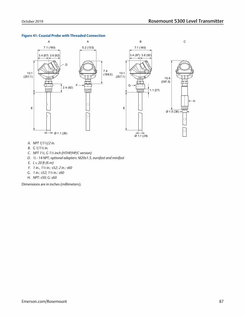
Figure 41: Coaxial Probe with Threaded Connection
E
5.2 (133)
7.4(188.5)
2.4 (62)
7.1 (180)
F
3.6 (92)3.4 (87)
Ø 1.1 (28)
10.1(257.1)
Ø 1.1 (28)
3.4 (87)
1.1 (27)
7.1 (180)
3.6 (92)
10.1(257.1)
H
15.6(397.5)
E
G
Ø 1.5 (38)
D
A A B C
A. NPT 1/1½/2 in.B. G 1/1½ in.C. NPT 1½, G 1½ inch (HTHP/HP/C version)D. ½ - 14 NPT; optional adapters: M20x1.5, eurofast and minifastE. L ≤ 20 ft (6 m)F. 1 in., 1½ in.: s52; 2 in.: s60
G. 1 in.: s52; 1½ in.: s60H. NPT: s50; G: s60
Dimensions are in inches (millimeters).
October 2019 Rosemount 5300 Level Transmitter
Emerson.com/Rosemount 87

Figure 42: Large Coaxial Probe with Flange Connection
7.1 (180)
3.4 (87) 3.6 (92)
Ø 1.7 (42)
A
B
10.1 (257.1)
5.2 (133)
7.4 (188.5)
15.6 (397.5)
C
2.4 (60)
2.4 (60)
A. ½ - 14 NPT; optional adapters: M20x1.5, eurofast and minifastB. L ≤ 20 ft. (6 m)C. HP/C version
Dimensions are in inches (millimeters).
Rosemount 5300 Level Transmitter October 2019
88 Emerson.com/Rosemount
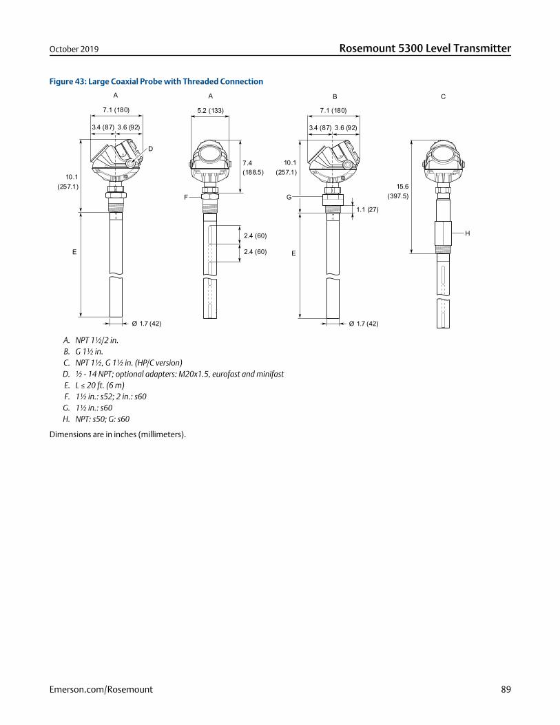
Figure 43: Large Coaxial Probe with Threaded Connection
7.1 (180)
3.4 (87) 3.6 (92)
D
E
10.1
Ø 1.7 (42)
5.2 (133)
7.4
7.1 (180)
3.4 (87) 3.6 (92)
E
Ø 1.7 (42)
1.1 (27)
A A B C
F G
H
(257.1) 15.6(397.5)
10.1(257.1)(188.5)
2.4 (60)
2.4 (60)
A. NPT 1½/2 in.B. G 1½ in.C. NPT 1½, G 1½ in. (HP/C version)D. ½ - 14 NPT; optional adapters: M20x1.5, eurofast and minifastE. L ≤ 20 ft. (6 m)F. 1½ in.: s52; 2 in.: s60
G. 1½ in.: s60H. NPT: s50; G: s60
Dimensions are in inches (millimeters).
October 2019 Rosemount 5300 Level Transmitter
Emerson.com/Rosemount 89

Figure 44: Integrated Still Pipe Vapor Probe for 3-in. Chambers and above
B
7.1 (180)
3.4 (87) 3.6 (92)
A
5.2 (133)
C
D
C
D
Ø 1.1 (28)
Ø 1.6 (42)
Min. 0.2 (5)Min. Ø 2 (50)
16 (397)
E
7.4 (188.5)
A. ½ - 14 NPT; optional adapters: M20x1.5, eurofast and minifastB. L ≤ 13 ft. 1 in. (4 m)C. Short reflector: 13.8 (350); Long reflector: 19.7 (500)D. Minimum 8.3 in. (210 mm) distance between water surface and reflector endE. Minimum 12 in. (300 mm)
Dimensions are in inches (millimeters).
Rosemount 5300 Level Transmitter October 2019
90 Emerson.com/Rosemount
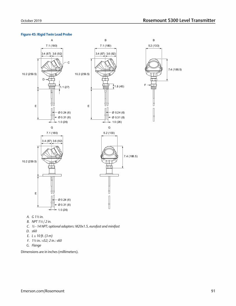
Figure 45: Rigid Twin Lead Probe
1.0 (26)
D
5.2 (133)
7.4 (188.5)
1.8 (45)
7.1 (180)
E
3.4 (87)
Ø 0.24 (6)Ø 0.31 (8)
F1.1 (27)
7.1 (180)
3.6 (92) 3.6 (92)3.4 (87)
10.2 (259.5)
E
10.2 (259.5)
E
10.2 (259.5)
1.0 (26)Ø 0.31 (8)Ø 0.24 (6)
Ø 0.24 (6)
Ø 0.31 (8)
3.4 (87) 3.6 (92)
7.1 (180) 5.2 (133)
7.4 (188.5)
1.0 (26)
A
G G
B B
C
A. G 1½ in.B. NPT 1½ / 2 in.C. ½ - 14 NPT; optional adapters: M20x1.5, eurofast and minifastD. s60E. L ≤ 10 ft. (3 m)F. 1½ in.: s52; 2 in.: s60G. Flange
Dimensions are in inches (millimeters).
October 2019 Rosemount 5300 Level Transmitter
Emerson.com/Rosemount 91
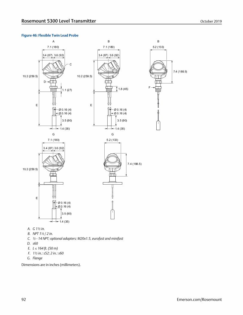
Figure 46: Flexible Twin Lead Probe
1.4 (35)
3.5 (90)
1.4 (35)
3.5 (90)
1.4 (35)
3.5 (90)
D
5.2 (133)
7.4 (188.5)
7.1 (180)
E
3.4 (87)
F1.1 (27) 1.8 (45)
7.1 (180)
3.6 (92) 3.6 (92)3.4 (87)
10.2 (259.5)
E
10.2 (259.5)
E
10.2 (259.5)
3.4 (87) 3.6 (92)
7.1 (180) 5.2 (133)
7.4 (188.5)
A
G G
B B
Ø 0.16 (4)Ø 0.16 (4)
Ø 0.16 (4)Ø 0.16 (4)
C
Ø 0.16 (4)Ø 0.16 (4)
A. G 1½ in.B. NPT 1½ / 2 in.C. ½ - 14 NPT; optional adapters: M20x1.5, eurofast and minifastD. s60E. L ≤ 164 ft. (50 m)F. 1½ in.: s52; 2 in.: s60G. Flange
Dimensions are in inches (millimeters).
Rosemount 5300 Level Transmitter October 2019
92 Emerson.com/Rosemount
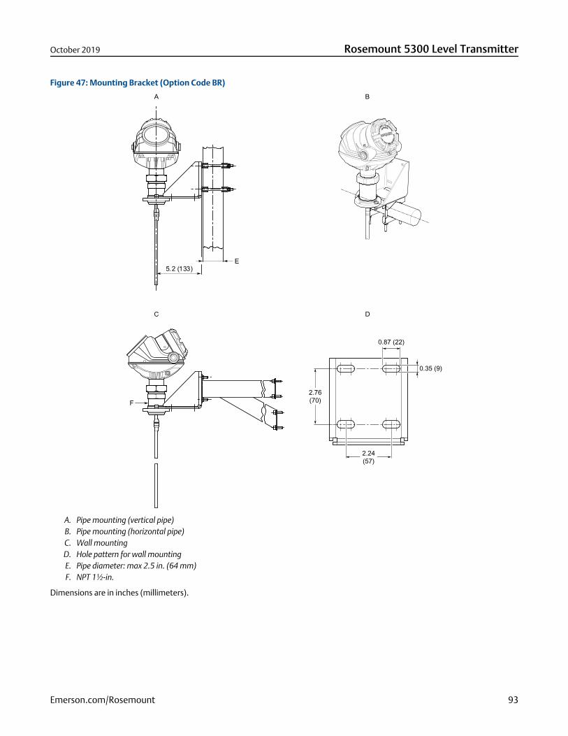
Figure 47: Mounting Bracket (Option Code BR)
5.2 (133)
F
A B
C D
E
2.24(57)
0.35 (9)
0.87 (22)
2.76(70)
A. Pipe mounting (vertical pipe)B. Pipe mounting (horizontal pipe)C. Wall mountingD. Hole pattern for wall mountingE. Pipe diameter: max 2.5 in. (64 mm)F. NPT 1½-in.
Dimensions are in inches (millimeters).
October 2019 Rosemount 5300 Level Transmitter
Emerson.com/Rosemount 93

Figure 48: Remote Housing (Option Code B1, B2, B3)
7.4 (188.5)
A
BC
5.2 (133)
5.2 (133)
7 (180)
3.4(87)
3.6(92)
D
2.2 (57)
2.8(70)
0.8 (20)
0.3 (7)
A. 3, 6, 9 ft. (1, 2, or 3 m)B. Rmin: 1.4 (35)C. Hmin: 6.9 (175) for Standard variant; 12.4 (315) for HTHP/HP/C variantD. Hole pattern for remote housing wall mounting
Dimensions are in inches (millimeters).
Rosemount 5300 Level Transmitter October 2019
94 Emerson.com/Rosemount
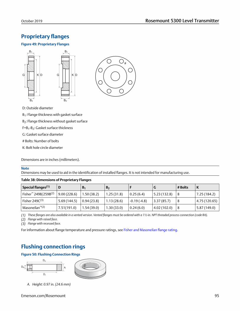
Proprietary flangesFigure 49: Proprietary Flanges
D: Outside diameter
B1: Flange thickness with gasket surface
B2: Flange thickness without gasket surface
F=B1-B2: Gasket surface thickness
G: Gasket surface diameter
# Bolts: Number of bolts
K: Bolt hole circle diameter
Dimensions are in inches (millimeters).
NoteDimensions may be used to aid in the identification of installed flanges. It is not intended for manufacturing use.
Table 38: Dimensions of Proprietary Flanges
Special flanges(1) D B1 B2 F G # Bolts K
Fisher™ 249B/259B(2) 9.00 (228.6) 1.50 (38.2) 1.25 (31.8) 0.25 (6.4) 5.23 (132.8) 8 7.25 (184.2)
Fisher 249C(3) 5.69 (144.5) 0.94 (23.8) 1.13 (28.6) -0.19 (-4.8) 3.37 (85.7) 8 4.75 (120.65)
Masoneilan™(2) 7.51(191.0) 1.54 (39.0) 1.30 (33.0) 0.24 (6.0) 4.02 (102.0) 8 5.87 (149.0)
(1) These flanges are also available in a vented version. Vented flanges must be ordered with a 1½-in. NPT threaded process connection (code RA).(2) Flange with raised face.(3) Flange with recessed face.
For information about flange temperature and pressure ratings, see Fisher and Masoneilan flange rating.
Flushing connection ringsFigure 50: Flushing Connection Rings
A. Height: 0.97 in. (24.6 mm)
October 2019 Rosemount 5300 Level Transmitter
Emerson.com/Rosemount 95
Table 39: Pressure and Temperature Rating for Flushing Ring up to Class 2500
Flushing connection rings Di Do DH
2 in. ANSI 2.12 (53.8) 3.62 (91.9) ¼ in. NPT
3 in. ANSI 3.60 (91.4) 5.00 (127.0) ¼ in. NPT
4 in. ANSI/DN100 3.60 (91.4) 6.20 (157.5) ¼ in. NPT
DN50 2.40 (61.0) 4.00 (102.0) ¼ in. NPT
DN80 3.60 (91.4) 5.43 (138.0) ¼ in. NPT
Rosemount 5300 Level Transmitter October 2019
96 Emerson.com/Rosemount

October 2019 Rosemount 5300 Level Transmitter
Emerson.com/Rosemount 97

Rosemount 5300 Level Transmitter October 2019
98 Emerson.com/Rosemount
October 2019 Rosemount 5300 Level Transmitter
Emerson.com/Rosemount 99

00813-0100-4530Rev. JA
October 2019
Global HeadquartersEmerson Automation Solutions6021 Innovation Blvd.Shakopee, MN 55379, USA
+1 800 999 9307 or +1 952 906 8888
+1 952 204 8889
North America Regional OfficeEmerson Automation Solutions8200 Market Blvd.Chanhassen, MN 55317, USA
+1 800 999 9307 or +1 952 906 8888
+1 952 204 8889
Latin America Regional OfficeEmerson Automation Solutions1300 Concord Terrace, Suite 400Sunrise, FL 33323, USA
+1 954 846 5030
+1 954 846 5121
Europe Regional OfficeEmerson Automation Solutions EuropeGmbHNeuhofstrasse 19a P.O. Box 1046CH 6340 BaarSwitzerland
+41 (0) 41 768 6111
+41 (0) 41 768 6300
Asia Pacific Regional OfficeEmerson Automation Solutions1 Pandan CrescentSingapore 128461
+65 6777 8211
+65 6777 0947
Middle East and Africa Regional OfficeEmerson Automation SolutionsEmerson FZE P.O. Box 17033Jebel Ali Free Zone - South 2Dubai, United Arab Emirates
+971 4 8118100
+971 4 8865465
Linkedin.com/company/Emerson-Automation-Solutions
Twitter.com/Rosemount_News
Facebook.com/Rosemount
Youtube.com/user/RosemountMeasurement
©2019 Emerson. All rights reserved.
Emerson Terms and Conditions of Sale are available upon request. The Emerson logo is atrademark and service mark of Emerson Electric Co. Rosemount is a mark of one of theEmerson family of companies. All other marks are the property of their respective owners.