Embed Size (px)
Citation preview

Reference Manual 00809-0100-4023, Rev DA
March 2006
Rosemount 3420
Fieldbus Interface Module
Product Discontinued
www.rosemount.com


Reference Manual 00809-0100-4023, Rev DA
March 2006 Rosemount 3420
Rosemount 3420 Fieldbus Interface Module (FIM)
Physical Device Revision 2.1Web Server Revision 2.3.19
Rosemount and the Rosemount logotype are registered trademarks of Rosemount Inc.PlantWeb is a registered trademark of one of the Emerson Process Management group of companies.Honeywell is a registered trademark of Honeywell Inc.All other marks are the property of their respective owners.FOUNDATION is a trademark of the Fieldbus Foundation.Modbus is a registered trademark of Schneider Automation, Inc.Cover Photo: 3402_housing_2-1.tif
NOTICE
Read this manual before working with the product. For personal and system safety, and for
optimum product performance, make sure you thoroughly understand the contents before
installing, using, or maintaining this product.
Within the United States, Emerson Process Management has
two toll-free assistance numbers:
Customer Central
Technical support, quoting, and order-related questions.
1-800-999-9307 (7:00 am to 7:00 pm CST)
North American Response Center
Equipment service needs.
1-800-654-7768 (24 hours—includes Canada)
Outside of the United States, contact your local Rosemount representative.
The products described in this document are NOT designed for nuclear-qualified
applications. Using non-nuclear qualified products in applications that require
nuclear-qualified hardware or products may cause inaccurate readings.
For information on Rosemount nuclear-qualified products, contact your local Rosemount
Sales Representative.
www.rosemount.com


Reference Manual 00809-0100-4023, Rev DA
March 2006 Rosemount 3420
Table of Contents
SECTION 1
Introduction
Overview. . . . . . . . . . . . . . . . . . . . . . . . . . . . . . . . . . . . . . . . . . . . . . . . . . . . . .1-1
Using this Manual. . . . . . . . . . . . . . . . . . . . . . . . . . . . . . . . . . . . . . . . . . . .1-1
Service and Support. . . . . . . . . . . . . . . . . . . . . . . . . . . . . . . . . . . . . . . . . .1-1
SECTION 2
Installation
Overview. . . . . . . . . . . . . . . . . . . . . . . . . . . . . . . . . . . . . . . . . . . . . . . . . . . . . .2-1
Safety Messages . . . . . . . . . . . . . . . . . . . . . . . . . . . . . . . . . . . . . . . . . . . .2-1
Warnings . . . . . . . . . . . . . . . . . . . . . . . . . . . . . . . . . . . . . . . . . . . . . . . . . .2-1
General Considerations . . . . . . . . . . . . . . . . . . . . . . . . . . . . . . . . . . . . . . .2-1
System Requirements . . . . . . . . . . . . . . . . . . . . . . . . . . . . . . . . . . . . . . . .2-2
Installation Procedure . . . . . . . . . . . . . . . . . . . . . . . . . . . . . . . . . . . . . . . . . . . .2-3
Software Installation. . . . . . . . . . . . . . . . . . . . . . . . . . . . . . . . . . . . . . . . . .2-3
OPC Installation . . . . . . . . . . . . . . . . . . . . . . . . . . . . . . . . . . . . . . . . . . . . .2-3
Physical Installation . . . . . . . . . . . . . . . . . . . . . . . . . . . . . . . . . . . . . . . . . .2-3
Mounting Procedure. . . . . . . . . . . . . . . . . . . . . . . . . . . . . . . . . . . . . . . . . .2-5
Grounding the FIM . . . . . . . . . . . . . . . . . . . . . . . . . . . . . . . . . . . . . . . . . . .2-5
Wiring the FIM . . . . . . . . . . . . . . . . . . . . . . . . . . . . . . . . . . . . . . . . . . . . . .2-5
FIM Input Power Connection . . . . . . . . . . . . . . . . . . . . . . . . . . . . . . . . . . .2-6
Connecting the Devices . . . . . . . . . . . . . . . . . . . . . . . . . . . . . . . . . . . . . . .2-6
Modbus Termination Setup . . . . . . . . . . . . . . . . . . . . . . . . . . . . . . . . . . . .2-7
RS485 Serial Interface . . . . . . . . . . . . . . . . . . . . . . . . . . . . . . . . . . . . . . . .2-8
SECTION 3Configuration
Private Networks . . . . . . . . . . . . . . . . . . . . . . . . . . . . . . . . . . . . . . . . . . . .3-1
3420 Network . . . . . . . . . . . . . . . . . . . . . . . . . . . . . . . . . . . . . . . . . . . . . . .3-2
Redundant Ethernet Configuration. . . . . . . . . . . . . . . . . . . . . . . . . . . . . . .3-4
Security . . . . . . . . . . . . . . . . . . . . . . . . . . . . . . . . . . . . . . . . . . . . . . . . . . .3-5
System Time Setup . . . . . . . . . . . . . . . . . . . . . . . . . . . . . . . . . . . . . . . . . .3-5
Page Options . . . . . . . . . . . . . . . . . . . . . . . . . . . . . . . . . . . . . . . . . . . . . . .3-6
Point Monitoring Pages . . . . . . . . . . . . . . . . . . . . . . . . . . . . . . . . . . . . . . .3-6
Setting Up the Page Columns . . . . . . . . . . . . . . . . . . . . . . . . . . . . . . . . . .3-8
Application Data Configuration. . . . . . . . . . . . . . . . . . . . . . . . . . . . . . . . . .3-8
Setting Up the Home Page . . . . . . . . . . . . . . . . . . . . . . . . . . . . . . . . . . . .3-9
Restart App . . . . . . . . . . . . . . . . . . . . . . . . . . . . . . . . . . . . . . . . . . . . . . . .3-9
Fieldbus Field Devices . . . . . . . . . . . . . . . . . . . . . . . . . . . . . . . . . . . . . . . . . . .3-9
Devices . . . . . . . . . . . . . . . . . . . . . . . . . . . . . . . . . . . . . . . . . . . . . . . . . . .3-9
Blocks. . . . . . . . . . . . . . . . . . . . . . . . . . . . . . . . . . . . . . . . . . . . . . . . . . . . .3-9
Application . . . . . . . . . . . . . . . . . . . . . . . . . . . . . . . . . . . . . . . . . . . . . . . .3-10
Advanced . . . . . . . . . . . . . . . . . . . . . . . . . . . . . . . . . . . . . . . . . . . . . . . . .3-11
Modbus . . . . . . . . . . . . . . . . . . . . . . . . . . . . . . . . . . . . . . . . . . . . . . . . . . . . . .3-15
Communication . . . . . . . . . . . . . . . . . . . . . . . . . . . . . . . . . . . . . . . . . . . .3-15
Mapping Fieldbus Tags to Modbus Registers (Web Interface) . . . . . . . .3-16
Mapping Fieldbus Tags to Modbus Registers (FTP) . . . . . . . . . . . . . . . .3-17
Predefined Diagnostic Registers . . . . . . . . . . . . . . . . . . . . . . . . . . . . . . .3-19
OLE for Process Control. . . . . . . . . . . . . . . . . . . . . . . . . . . . . . . . . . . . . . . . .3-20
www.rosemount.com
Reference Manual00809-0100-4023, Rev DA
March 2006Rosemount 3420
Snapshot Files . . . . . . . . . . . . . . . . . . . . . . . . . . . . . . . . . . . . . . . . . . . . . . . .3-21
Snapshot File Setup. . . . . . . . . . . . . . . . . . . . . . . . . . . . . . . . . . . . . . . . .3-21
New or Edit Snapshot Data . . . . . . . . . . . . . . . . . . . . . . . . . . . . . . . . . . .3-21
Snapshot File Format . . . . . . . . . . . . . . . . . . . . . . . . . . . . . . . . . . . . . . . .3-22
Retrieving Snapshot File . . . . . . . . . . . . . . . . . . . . . . . . . . . . . . . . . . . . .3-23
Trend Collection . . . . . . . . . . . . . . . . . . . . . . . . . . . . . . . . . . . . . . . . . . . . . . .3-23
Trend Settings . . . . . . . . . . . . . . . . . . . . . . . . . . . . . . . . . . . . . . . . . . . . .3-23
Trend Collections . . . . . . . . . . . . . . . . . . . . . . . . . . . . . . . . . . . . . . . . . . .3-24
View Trend . . . . . . . . . . . . . . . . . . . . . . . . . . . . . . . . . . . . . . . . . . . . . . . .3-24
SECTION 4Operation and
Maintenance
Overview. . . . . . . . . . . . . . . . . . . . . . . . . . . . . . . . . . . . . . . . . . . . . . . . . . . . . .4-1
Diagnostics . . . . . . . . . . . . . . . . . . . . . . . . . . . . . . . . . . . . . . . . . . . . . . . . . . . .4-2
Fieldbus Segments . . . . . . . . . . . . . . . . . . . . . . . . . . . . . . . . . . . . . . . . . .4-2
Alarm Log . . . . . . . . . . . . . . . . . . . . . . . . . . . . . . . . . . . . . . . . . . . . . . . . . .4-2
Advanced . . . . . . . . . . . . . . . . . . . . . . . . . . . . . . . . . . . . . . . . . . . . . . . . . .4-2
Monitor . . . . . . . . . . . . . . . . . . . . . . . . . . . . . . . . . . . . . . . . . . . . . . . . . . . . . . .4-5
Alarm Notification . . . . . . . . . . . . . . . . . . . . . . . . . . . . . . . . . . . . . . . . . . . .4-6
Alarm Summary . . . . . . . . . . . . . . . . . . . . . . . . . . . . . . . . . . . . . . . . . . . . .4-7
Acknowledge an Alarm . . . . . . . . . . . . . . . . . . . . . . . . . . . . . . . . . . . . . . .4-7
Application Summary . . . . . . . . . . . . . . . . . . . . . . . . . . . . . . . . . . . . . . . . .4-7
Trend . . . . . . . . . . . . . . . . . . . . . . . . . . . . . . . . . . . . . . . . . . . . . . . . . . . . . . . .4-8
Graphs . . . . . . . . . . . . . . . . . . . . . . . . . . . . . . . . . . . . . . . . . . . . . . . . . . . .4-8
Reports. . . . . . . . . . . . . . . . . . . . . . . . . . . . . . . . . . . . . . . . . . . . . . . . . . . .4-8
TearOff . . . . . . . . . . . . . . . . . . . . . . . . . . . . . . . . . . . . . . . . . . . . . . . . . . . .4-8
Explorer . . . . . . . . . . . . . . . . . . . . . . . . . . . . . . . . . . . . . . . . . . . . . . . . . . . . . .4-9
SECTION 5Troubleshooting
Troubleshooting . . . . . . . . . . . . . . . . . . . . . . . . . . . . . . . . . . . . . . . . . . . . . . . .5-1
APPENDIX AReference Data
Specifications . . . . . . . . . . . . . . . . . . . . . . . . . . . . . . . . . . . . . . . . . . . . . . . . . A-1
Functional Specifications . . . . . . . . . . . . . . . . . . . . . . . . . . . . . . . . . . . . . A-1
Performance Specifications . . . . . . . . . . . . . . . . . . . . . . . . . . . . . . . . . . . A-2
Physical Specifications. . . . . . . . . . . . . . . . . . . . . . . . . . . . . . . . . . . . . . . A-2
Communication Specifications . . . . . . . . . . . . . . . . . . . . . . . . . . . . . . . . . A-3
Dimensional Drawings . . . . . . . . . . . . . . . . . . . . . . . . . . . . . . . . . . . . . . . . . . A-4
Ordering Information. . . . . . . . . . . . . . . . . . . . . . . . . . . . . . . . . . . . . . . . . . . . A-5
APPENDIX BApproval
Information
Approved Manufacturing Locations . . . . . . . . . . . . . . . . . . . . . . . . . . . . . B-1
European Union Directive Information . . . . . . . . . . . . . . . . . . . . . . . . . . . B-1
Hazardous Location Certifications . . . . . . . . . . . . . . . . . . . . . . . . . . . . . . B-1
European Certification . . . . . . . . . . . . . . . . . . . . . . . . . . . . . . . . . . . . . . . B-2
IECEx Certification . . . . . . . . . . . . . . . . . . . . . . . . . . . . . . . . . . . . . . . . . . B-2
APPENDIX CFieldbus Status
Values
Fieldbus Status Values . . . . . . . . . . . . . . . . . . . . . . . . . . . . . . . . . . . . . . . . . C-1
TOC-2

Reference Manual00809-0100-4023, Rev DA
March 2006 Rosemount 3420
APPENDIX DModbus Configuration in
Honeywell® TDC APM/HPM
Modbus Configuration in Honeywell® TDC APM/HPM . . . . . . . . . . . . . . . . . D-1
APPENDIX EInteger Scaling
Integer Scaling . . . . . . . . . . . . . . . . . . . . . . . . . . . . . . . . . . . . . . . . . . . . . . . . E-1
Configuring Scaled Integers . . . . . . . . . . . . . . . . . . . . . . . . . . . . . . . . . . . . . . E-1
Step 1: Determine Maximum Integer . . . . . . . . . . . . . . . . . . . . . . . . . . . . E-2
Step 2: Determine the Gain (Slope) . . . . . . . . . . . . . . . . . . . . . . . . . . . . . E-2
Step 3: Determine Offset . . . . . . . . . . . . . . . . . . . . . . . . . . . . . . . . . . . . . E-2
Using Integer Scaling to Define Range Limits . . . . . . . . . . . . . . . . . . . . . . . . E-3
APPENDIX FAMS™ Suite: Intelligent Device
Manager with Rosemount 3420
Benefits . . . . . . . . . . . . . . . . . . . . . . . . . . . . . . . . . . . . . . . . . . . . . . . . . . . . . . .F-1
Network Configuration for Rosemount 3420. . . . . . . . . . . . . . . . . . . . . . . . . . .F-2
Using the Foundation™ Fieldbus HSE System Interface in
AMS Device Manager. . . . . . . . . . . . . . . . . . . . . . . . . . . . . . . . . . . . . . . . . .F-2
AMS Tags . . . . . . . . . . . . . . . . . . . . . . . . . . . . . . . . . . . . . . . . . . . . . . . . .F-3
The 3420 Web Browser and AMS Device Manager . . . . . . . . . . . . . . . . . . . . .F-3
Launching the 3420 Web Browser from AMS Device Manager . . . . . . . . . . . .F-3
APPENDIX GCSI 9120 Machinery Health
Transmitter
Purpose of the CSI 9210 Appendix . . . . . . . . . . . . . . . . . . . . . . . . . . . . . . . . G-1
Introduction . . . . . . . . . . . . . . . . . . . . . . . . . . . . . . . . . . . . . . . . . . . . . . . . . . . G-1
Scope . . . . . . . . . . . . . . . . . . . . . . . . . . . . . . . . . . . . . . . . . . . . . . . . . . . . . . . G-2
Block Configuration . . . . . . . . . . . . . . . . . . . . . . . . . . . . . . . . . . . . . . . . . G-2
Alarm Configuration . . . . . . . . . . . . . . . . . . . . . . . . . . . . . . . . . . . . . . . . . G-3
Point Pages Configuration - MAI Blocks . . . . . . . . . . . . . . . . . . . . . . . . . G-4
Point Pages Configuration-AI blocks . . . . . . . . . . . . . . . . . . . . . . . . . . . . G-6
Transducer Block Configuration. . . . . . . . . . . . . . . . . . . . . . . . . . . . . . . . G-7
Health MAI Block Configuration . . . . . . . . . . . . . . . . . . . . . . . . . . . . . . . . G-7
Temperature MAI Block Configuration . . . . . . . . . . . . . . . . . . . . . . . . . . . G-8
Health AI Block Configuration . . . . . . . . . . . . . . . . . . . . . . . . . . . . . . . . . G-8
Temperature AI Block Configuration . . . . . . . . . . . . . . . . . . . . . . . . . . . . G-9
Speed AI Block Configuration . . . . . . . . . . . . . . . . . . . . . . . . . . . . . . . . . G-9
Channel Mapping . . . . . . . . . . . . . . . . . . . . . . . . . . . . . . . . . . . . . . . . . . . G-9
Glossary Networking Definitions . . . . . . . . . . . . . . . . . . . . . . . . . . . . . . . . . . . . . . . . . . H-1
Fieldbus Definitions . . . . . . . . . . . . . . . . . . . . . . . . . . . . . . . . . . . . . . . . . . . . H-2
TOC-3

Reference Manual00809-0100-4023, Rev DA
March 2006Rosemount 3420
TOC-4

Reference Manual 00809-0100-4023, Rev DA
March 2006 Rosemount 3420
Section 1 Introduction
OVERVIEW This manual provides installation and troubleshooting instructions for the
Rosemount 3420 Fieldbus Interface Module (FIM).
Using this Manual The sections in this manual provide information on installing, operating, and
maintaining the Rosemount 3420 Fieldbus Interface Module.
• Section 2: Installation contains mechanical and electrical installation
instructions.
• Section 3: Configuration provides instruction on commissioning and
operating the Rosemount 3420 Fieldbus Interface Module. Information on software functions, configuration parameters, and online variables
are also included.
• Section 4: Operation and Maintenance contains operation and
maintenance techniques.
• Section 5: Troubleshooting provides troubleshooting techniques for the most common operations.
• Appendix A: Reference Data supplies reference and specification data,
as well as ordering information.
• Appendix B: Approval Information contains intrinsic safety approval information, European ATEX directive information, and approval.
• Appendix C: Fieldbus Status Values contains fieldbus function block
output status codes.
• Appendix D: Modbus Configuration in Honeywell® TDC APM/HPM
• Appendix E: Integer Scaling contains information on configuring and
scaling integers.
• Appendix F: AMS™ Suite: Intelligent Device Manager with Rosemount
3420
• Appendix G: CSI 9120 Machinery Health Transmitter
Service and Support To expedite the return process outside of the United States, contact the
nearest Rosemount representative.
Within the United States, call the Rosemount National Response Center using
the 1-800-654-RSMT (7768) toll-free number. This center, available 24 hours
a day, will assist you with any needed information or materials.
The center will ask for product model and serial numbers, and will provide a
Return Material Authorization (RMA) number. The center will also ask for the
process material to which the product was last exposed.
www.rosemount.com

Reference Manual00809-0100-4023, Rev DA
March 2006Rosemount 3420
Rosemount National Response Center representatives will explain the
additional information and procedures necessary to return goods exposed to
hazardous substance can avoid injury if they are informed of and understand
the hazard. If the product being returned was exposed to a hazardous
substance as defined by OSHA, a copy of the required Material Safety Data
Sheet (MSDS) for each hazardous substance identified must be included with
the returned goods.
1-2

Reference Manual 00809-0100-4023, Rev DA
March 2006 Rosemount 3420
Section 2 Installation
Overview . . . . . . . . . . . . . . . . . . . . . . . . . . . . . . . . . . . . . . . page 2-1
Installation Procedure . . . . . . . . . . . . . . . . . . . . . . . . . . . . page 2-3
OVERVIEW Dimensional drawings are included in Appendix A: Reference Data. A PC with
an Ethernet port is required to perform the initial configuration of the device.
Safety Messages Instructions and procedures in this section may require special precautions to
ensure the safety of the personnel performing the operations. Information that raises potential safety issues is indicated by a warning symbol ( ). Please
refer to the following safety messages before performing an operation
preceded by this symbol.
Warnings
General Considerations The Rosemount 3420 may be mounted in any General Purpose location. Be
sure the covers are secured tightly to prevent exposure of the electronics to
moisture and contamination.
CONFIGURATION NOTE
Before connecting the fieldbus segments to the Rosemount 3420, you must
first connect a PC and configure the Rosemount 3420. Once the Plug and Play features have been set up you can then make the final connection of the
segments to the Rosemount 3420 terminal strip.
Explosions could result in death or serious injury:
• Do not remove the transmitter from its mounting enclosure in explosive
atmospheres when the circuit is live.
• Verify that the operating atmosphere of the transmitter is consistent with the
appropriate hazardous locations certifications.
Electrical shock could cause death or serious injury. If the device is installed in a
high-voltage environment and a fault condition or installation error occurs, high voltage may
be present on transmitter leads and terminals.
• Use extreme caution when making contact with the leads and terminals.
Failure to follow these installation guidelines could result in death or serious injury:
• Make sure only qualified personnel perform the installation.
www.rosemount.com

Reference Manual00809-0100-4023, Rev DA
March 2006Rosemount 3420
System Requirements Operating System:
• Windows 2000, service pack 4
• Windows XP (Home or Professional), service pack 1
• Windows 2003
• Windows Vista
(or newer)
If the operating system requirement is not met, the setup will display a
message and stop.
Applications:
• Internet Explorer 6.0
• Sun Microsystems™ Java™ Runtime 1.4.1
(or newer)
If the user manual is being installed, the following application is also required:
• Adobe® Acrobat® 5.0
(or newer)
If the Network Assistant or OPC Proxy Setup utilities are being installed, the
following application is also required:
• .NET Framework 1.1
If any of the above requirements are not met, the setup disc will install the
following:
• Internet Explorer 6.0 service pack 1
• Sun Microsystems™ Java™ Runtime 1.5.0_04
• Adobe® Acrobat Reader® 7.0
• .NET Framework 1.1
Hard disk space:
• Maximum installation (including all upgrades performed by the setup
disc): 250 mb
• Typical installation (all features, but none of the above installed): 35 mb
2-2

Reference Manual 00809-0100-4023, Rev DA
March 2006 Rosemount 3420
INSTALLATION PROCEDURE
Software Installation To prepare a PC to communicate with the 3420, insert the Setup Assistant &
Support Files CD that came with your 3420. Follow the directions in the
installation windows to install the desired components.
At the Setup Type screen, select Complete or Custom depending on your
specific needs. Custom setup allows you to choose whether to install the
following options:
Once you have selected the desired options, continue with installation by
clicking Next. Other selectable optional features include a desktop icon for the
network assistant, a desktop icon for OPC Proxy Setup, and whether to start
OPC deviceCOM server automatically.
OPC Installation While using an OPC client (such as Matrikon OPC Explorer), install the OPC
Proxy Setup application. This will allow OPC Client users to define the IP
address of the 3420 OPC Server to access.
NOTE:
If you need access to more than one 3420 OPC Server, all IP addresses
should be defined in the OPC Proxy Setup application.
When the OPC Proxy Setup is completed, the OPC Client will list the
available OPC Servers. You may then choose and connect to the desired
server(s).
Once connected, add groups and tags for OPC Client access.
Physical Installation For dimensional drawing information refer to Appendix A: Reference Data on
page A-4.
The cast aluminum housing encloses the electronics circuitry of the FIM. The
front of the enclosure has two covers; an upper cover and a junction box
cover.
The upper cover provides access to the electronics assembly which includes the microprocessor, fieldbus interface boards, fieldbus power
conditioners/terminators, and the power supply board.
3420 User Interface
When this feature is selected, setup will install any additional software
required to use this PC as a user interface for the 3420. This may
include installing Microsoft Internet Explorer and Sun Microsystems
Java Runtime.
3420 Reference Manual
When this feature is selected, setup will install an electronic copy of
the Rosemount 3420 Reference Manual (this manual) on the PC. This
may include installing Adobe Acrobat Reader.
Network Assistant
When this feature is selected, setup will install Network Assistant, a
program that automates network configuration changes to support
3420 configuration.
OPC Client RuntimeWhen this feature is selected, setup will install software that will allow
OPC clients running on this PC to access the 3420.
OPC Proxy Setup
When this feature is selected, setup will install the OPC Proxy Setup
program to configure which 3420s will be accessed by OPC clients
running on this PC
2-3

Reference Manual00809-0100-4023, Rev DA
March 2006Rosemount 3420
The junction box cover provides access to the terminal block. To open either
cover of the enclosure, use a 1/4 inch blade screwdriver to remove the
appropriate screw on the unhinged side of the enclosure.
2-4

Reference Manual 00809-0100-4023, Rev DA
March 2006 Rosemount 3420
Mounting Procedure The FIM can be mounted to a support bracket on a wall or to a pipe.
Mounting the FIM to a Support Bracket
The following hardware and tools are needed:
• Four 15/16 inch bolts
• Mounting support
• 3/8 inch drill
• 1/2 inch socket-head wrench
Mount the FIM by doing the following:
1. Drill four 3/8 inch (9.525 mm) holes in the support bracket to which the
FIM will be mounted.
2. Using a 1/2 inch socket-head wrench, attach the FIM to the support
bracket with four 15/16 inch bolts.
Mounting the FIM to a Pipe
The following hardware tools are needed:
• Pipe mount with holes spaced 2.81 inch (71 mm) apart horizontally and
11.15 inch (283 mm) apart vertically.
• Two 5/16 inch U-bolts
• 1/2 inch socket-head wrench
Mount the FIM by doing the following:
1. Insert one U-bolt around the pipe and through the top mounting holes of the pipe mount and the FIM and another U-bolt through the bottom
mounting holes of the pipe mount and the FIM.
2. Using a 1/2 inch socket-head wrench, fasten nuts to the U-bolts.
Grounding the FIM If mounting the Rosemount 3420 in the field, ground the FIM with a
connection of 1 Ω or less leading from the external grounding lug to earth
ground. If mounting the FIM in the control room, a cabinet ground is sufficient.
In either location, follow local or plant electrical codes.
Wiring the FIM FIM wiring is done in the terminal block. For access to the terminal block,
open the junction box cover following the instruction “Installation Procedure”
on page 2-3. The terminal block label is located on the inside of the FIM
junction box cover.
At the bottom of the junction box in 1/2 inch NPT conduit entries are four plastic
plugs that were placed there at the factory. Four metal plugs were shipped with the FIM and are used to seal any unused ports.
The FIM case should always be grounded in accordance with national and
local electrical codes. The most effective grounding method is direct
connection to earth ground with minimal impedance.
The internal Ground Connection located with the supply terminals is the
Internal Ground Connection screw. This screw is identified by the following
symbol:
2-5

Reference Manual00809-0100-4023, Rev DA
March 2006Rosemount 3420
NOTE
Grounding the FIM case via threaded conduit connection may not provide
sufficient ground.
The wiring should include an external power shut-off switch or an external
circuit breaker. This device should be located near the FIM.
Figure 2-1. Terminal Wiring Diagram
FIM Input Power Connection
The FIM is designed to be powered by 24 V dc power. Use a power supply
suitable for 185°F with sufficient capacity to power both the FIM and all of the
fieldbus devices that are connected to it. The Rosemount 3420 requires 500
mA. About 300 mA of additional current should be allocated for each H1 segment if the unit is configured with internal power conditioners. The positive
and negative power terminals are found on the left side of the terminal block.
A case ground is also found on the left hand side of the compartment.
Connecting the Devices Ethernet
The 3420 is equipped with one or two 10/100 Base-T Ethernet interface
receptacles on the left side of the terminal block. Connect the FIM to the PC
that will be used for configuration, using the crossover cable provided with the
3420. You may also connect the 3420 to an existing Ethernet Hub, Switch or
Router.
The second Ethernet port on the 3420 terminal block is an optional
factory-configured redundant Ethernet port. (ordering option Output Code 2)
Fieldbus
The fieldbus terminals are found on the right side of the terminal block in 4
sets of three terminals for the positive and negative conductors and a shield.
Although the FIM is not polarity sensitive, other components in the segment
such as junction blocks may require correct polarity.
Modbus
The Modbus interface terminals are located in the upper-middle of the wiring
block next to the power input. The Modbus interface is polarity sensitive.
Connect the negative to the right most terminal (B) and the positive to the left
terminal (A).
+ +
+
+
+
-
- -
--A B S S
S S
S
24 V DCPower Input Modbus Fieldbus 1 Fieldbus 2
Fieldbus 3 Fieldbus 4
Tx Rx
Ethernet 1
Ethernet 2
Case
Fiber Optic Ethernet
3420/3420IA02.EPS
2-6

Reference Manual 00809-0100-4023, Rev DA
March 2006 Rosemount 3420
Modbus Termination Setup
NOTE:
Do not open the 3420 electronics housing in an explosive atmosphere.
Modbus RTU is transmitted on an RS485 physical layer. Three dip-switches
are provided to enable the RS485 circuitry with a network terminator. The
switches are found inside the electronics housing on the RS485
communication board located in the top center of the housing. Switch 2 places a 120 ohm terminator on the bus. This would be used to match cable
impedance if needed to dampen reflections on long cable runs. Its use will
depend on the baud rate and cable length of the Modbus network.
Switches 1 and 3 are connected to pull-up and pull-down resisters on the
Modbus network. These resisters are used to prevent noise from being
interpreted as valid communications during periods when no communications
are occurring on the network. Only one set is required on an RS485 network.
Figure 2-2. Modbus Setup
3420/3420FA01.EPS
2-7

Reference Manual00809-0100-4023, Rev DA
March 2006Rosemount 3420
RS485 Serial Interface The RS485 standard describes a balanced transmission line operating in a
shared or multi-drop model. As many as 32 driver/receiver pairs can share a
single network.
Figure 2-3 shows a typical two-wire multi-drop network such as used with the Rosemount 3420. The RS485 specifications indicate that the transmission
line should be terminated at both ends of the network. However termination
should only be used with high data rates above 115kb and long cable runs so
it should not be necessary with the transmission rates used by the
Rosemount 3420.
Figure 2-3. Typical two-wire multi-drop network.
3420/3420HA04.EPS
2-8

Reference Manual 00809-0100-4023, Rev DA
March 2006 Rosemount 3420
Section 3 Configuration
Fieldbus Field Devices . . . . . . . . . . . . . . . . . . . . . . . . . . . . page 3-9
Modbus . . . . . . . . . . . . . . . . . . . . . . . . . . . . . . . . . . . . . . . . page 3-15
Snapshot Files . . . . . . . . . . . . . . . . . . . . . . . . . . . . . . . . . . page 3-21
Trend Collection . . . . . . . . . . . . . . . . . . . . . . . . . . . . . . . . . page 3-23
Private Networks To configure the Rosemount 3420, a private network between a PC and the
Rosemount 3420 must first be established. This can be done with a PC
dedicated to the Rosemount 3420 or a PC used for another purpose can be
temporarily configured for the task. If a PC from another network is used,
carefully record the current IP address and other settings so the PC can be
returned to its original network when configuration of the Rosemount 3420 is
finished. If using a PC attached to another network, shut down the PC and remove it from the network before proceeding to set up the Rosemount 3420
private network.
Configure from the CD
The simplest way to configure the PC for use with the 3420 is to use the
Network Assistant installed from the CD included with the 3420.
Configuration of the FIM is done through its web interface. To access the device, you must create a private LAN with a subnet of 192.168.1.XX. The
FIM will appear on this LAN at the IP address 192.168.1.10.
1. Using the cross-over Ethernet cable, attach your PC to the
Rosemount 3420.
2. Launch the network assistant on your PC by double-clicking on its
desktop icon or by selecting it from the start menu.
3. If prompted, select the network adapter that you connected to the
3420.
4. Click on the "Direct" button to establish a direct connection to the
3420.
When you are ready to remove the PC from the 3420 first open the Network
Assistant and select Normal to return the settings of the PC to their original
values. To check the connection, proceed to step 5 below.
Explosions could result in death or serious injury:
• In an Explosion-Proof and Flame-Proof environment, do not open the Rosemount
3420 electronic housing in an explosive atmosphere.
• Cover must be fully engaged to meet Explosion-Proof requirements.
www.rosemount.com

Reference Manual00809-0100-4023, Rev DA
March 2006Rosemount 3420
The PC address and host settings can also be changed manually using
the following procedure for Windows XP. The procedure for other
operating systems may vary slightly:
1. On your PC, install the Java Plug-in found on the CD provided with
the 3420. You can also find the Java Plug-in at:
http://java.com/
2. Download the Java software and install it on your computer.
3. Under Network Connections in your Control Panel:
a. Select Local Area Connection
b. Right click to select Properties, select Internet Protocol
(TCP/IP), then click the Properties button
c. Select the Use the following IP address button and set your IP
address to 192.168.1.12
d. Set your Network address to 255.255.255.0
e. Select OK or Close for each of the settings windows that have
been opened.
4. Using the crossover ethernet cable, attach your PC to the Rosemount
3420. Add an entry in your hosts for the fim3420.
5. Check the Network connection by typing: PING fim3420 in the
Command Prompt. If you see replies you know you have the hosts file
setup properly.
6. Open your Internet Explorer browser.
7. In your browser address bar type: http://fim3420.
8. Press Enter. (You should get a message displayed that you are being
redirected to the 3420 home page.)
9. At the Enter Network Password box:
a. LogOn as User: admin
b. Password of: fieveladmin
NOTE
Before leaving any web page that you make changes to, click Submit, or all
your changes will be lost.
3420 Network Click Setup>Network>Address on the left menu tree to enter network
parameters. If the FIM is connected to a LAN or if more than one FIM will be
used on a private network, the unit will need to be given a new IP address and
a new hostname. A new entry will need to be added to your host file with the
new IP address and Host name using the Network Assistant or the manual
procedure described above.
Address
If you will be attaching the 3420 to an internal Intranet, you may select to have
the device attain an IP address via DHCP or be statically assigned an IP
address (Figure 3-1). Contact your network administrator if you are not sure
which selection is appropriate.
3-2

Reference Manual 00809-0100-4023, Rev DA
March 2006 Rosemount 3420
NOTE
If you accidentally misconfigure the network settings and can not reach the
device at the new IP address, return the device to the private LAN you used
for initial configuration with only the one 3420 connected. You can still access
the FIM by its default IP address (192.168.1.10) in this environment.
Figure 3-1. Network Address
Backup Address
This address should only need to be changed if your internal corporate
network uses non-routable IP addresses for its internal use and they use the
192.168.1.xxx subnet. If this is the case, you will want to change the default IP
address to an address that does not conflict with an address that is in use.
Please consult your network administrator if you can not make that
determination yourself.
Click Setup>Network>Backup Address to configure the backup IP Address
settings.
Be very careful when changing these settings. The device can be rendered
unusable if these values are modified incorrectly.
3420/REV CA/NETWORKADDRESS.TIF
3-3

Reference Manual00809-0100-4023, Rev DA
March 2006Rosemount 3420
Redundant Ethernet Configuration
If the 3420 has been ordered with a redundant network interface, the network
setup page (Setup>Network>Address) will display a secondary interface as
shown below.
The second network interface allows the 3420 to be accessed with two
separate network addresses. The redundant interfaces provide the 3420 with
a degree of fault tolerance to network failures. The following network topology
is supported:
3420/SCREENSHOTS/REDUNDANT.TIF
LAN A(Subnet 192.168.1.XX)
LAN B(Subnet 192.168.2.XX)
PCPC PCPC
3-4

Reference Manual 00809-0100-4023, Rev DA
March 2006 Rosemount 3420
NOTE
The subnet numbers listed in the diagram are an example. Any valid network
subnets are acceptable.
If you will be using the redundant ethernet feature, you may select to have the
device obtain an IP address via DHCP or be statically assigned an IP for the
secondary interface. Contact your network administrator if you are not sure
which selection is appropriate.
Security Click Setup>Security to change the passwords. These passwords allow for
varying levels of application access. The administrator can modify any system
or field device setting. In contrast, the operator is only able to modify some
Fieldbus parameters. Use caution when changing the administrator
password. If the administrator password is lost, you will not be able to set up
the Rosemount 3420. The FIM is shipped with the following default
passwords:
Table 3-1. Default Passwords
Table 3-2. Access Table
System Time Setup Click Setup>Time to configure the system time. If your Rosemount 3420 is
connected to a network and you want to use this feature, you should select a
timeserver at your facility or one near you geographically to insure accurate
time adjustments. The device will function properly with this feature disabled
but data time stamps will be less accurate and time updates must be entered
for each Rosemount 3420.
ID PASSWORD
Executive (exec) showme
Operator (oper) runit
Maintenance (maint) keepitgoing
Administrator (admin) fieveladmin
Role HTML Access Explorer view Access
Executive (exec) With the exception of factory settings
(Setup/factory.html), can get any page
(Read-Only access).
Read-only access to AI and
MAI blocks. (VFDs and
other blocks are not visible.
Operator (oper) No additional privileges Same values as executive,
but with read-write access.
Maintenance (maint) • Can set device PD tags
• Can set block tags
• Can configure Modbus
communications
• Can configure Modbus register map
• Can configure snapshots
• Can configure Plug and Play and
Operating Modes
All parameters of all blocks
(Read-Write).
Administrator
(admin)• Can configure network settings
(address, default).
• Can set passwords
• Can set time settings
• Can set home page options
• Can restart applications
No additional privileges
3-5

Reference Manual00809-0100-4023, Rev DA
March 2006Rosemount 3420
To use a network time server, check the box Enable Network Time Protocol,
enter the IP address of the time server and select the appropriate NTP packet
version.
Alternately you can set the time manually. This is accomplished by
unchecking the “Enable Network Time Protocol” check box. This will enable
you to enter information into the “Date” and “Time” fields.
Page Options Click Setup>Page Options to configure the point monitor and application
monitor pages. You can also select which page you wish to use as the 3420
home page.
Point Monitoring Pages Point Monitor Pages provide a means to view the PV or Output of a Function
Block and its status on one or more web pages. Multiple pages can be
configured to fit the application.
Click Setup>Page Options>Point Pages to display the current list of Point
Monitor Pages.
Figure 3-2. Point Monitor Page
To create a new Page click New. To edit an existing page click on Edit to the
right of the page name.
The editing screen provides a means of selecting the system tags that you
wish to include on the page.
3420/REV CA/POINTPAGES.TIF
3-6

Reference Manual 00809-0100-4023, Rev DA
March 2006 Rosemount 3420
Figure 3-3. Editing a new page
To add a new tag, click on New Entry and a blank line will be added to the
page. Then select the icon to the right of Point Name to select one of the tags
connected to the system.
Figure 3-4. Choose a Value
Continue the same process until all of the tags are entered. Then click
Submit at the bottom of the page.
NOTE
Only enabled blocks will appear in the menu. To enable blocks, see Blocks on
page 3-9.
3420/REV CA/EDITINGPAGE.TIF
3420/REV CA/CHOOSEVALUE.TIF
3-7

Reference Manual00809-0100-4023, Rev DA
March 2006Rosemount 3420
Setting Up the Page Columns
When you are finished setting up the point pages, click on Setup>Page
Options>Point Columns on the left menu. This page allows you to select
which columns you want displayed on the Point Monitoring Pages.
Figure 3-5. Point Monitor Columns
Check the columns you wish displayed and click on Submit. To view a Point
Monitoring Page see Monitor on page 4-5.
Application Data
Configuration
To configure the data for the monitor application, click Setup>Page
Options>App Data.
A monitoring page is automatically created for each application that is
configured on the 3420 Fieldbus segments. Check the fields that you wish to
display and then click Submit.
3420/REV CA/COLUMNS.TIF
3-8

Reference Manual 00809-0100-4023, Rev DA
March 2006 Rosemount 3420
Setting Up the Home Page
To select the first screen seen on the startup of the web interface click
Setup>Page Options>Home Pages. Check either the Menu Page (default),
Fieldbus Diagnostics, or one of the Point Monitoring Pages. Then click
Submit.
Figure 3-6. Home Page
Restart App Click Setup>Restart Apps to restart the Rosemount 3420 application
software. This is not needed during normal operation but may be required
when adding a device description or during troubleshooting of a system issue.
Simply select Yes to restart or No to abort. The restart will take about 1-5
minutes, after which the FIM displays the message “Finished restart of the
3420 software.”
FIELDBUS FIELD DEVICES
The FIM collects data based on the tag of the function blocks in the devices. If
the devices are not pre-configured with this information it can be edited using
the FIM web interface.
Devices Click Setup>Fieldbus>Devices to rename the Physical Devices (PD) tags
for individual devices. If the device is not already identified with a PD tag you
can use this display to enter them into the device. Tag names may be 32 characters in length and are case sensitive. Once all of the device PD tags
have been entered, click Submit. Allow 2 minutes for the update to take effect
if several tags are changed at once.
Blocks Click Setup>Fieldbus>Blocks to set up your fieldbus blocks. If the device’s
function blocks are not already identified with a tag then you can use this
display to enter them into the device. This tag information is used to assign
Modbus registers, OPC Connections and other functions in the FIM. Block
names (tags) may be 32 characters in length and are case sensitive. Normally
not all function blocks will be used in an application. This display allows only
those blocks in actual use to be scheduled to optimize the performance of the
Rosemount 3420. Also, each block's alarm handling can be individually
enabled so alarms are automatically reported and logged.
3420/REV CA/PAGEOPTIONS.TIF
3-9

Reference Manual00809-0100-4023, Rev DA
March 2006Rosemount 3420
Enable Blocks
To enable a block, locate the device on the Block Setup page using the
Previous and Next buttons. When you find the block you want to enable,
simply check the box under Enable Block, then click Submit.
Enable Alarms
To enable an alarm, locate the device on the Block Setup page using the
Previous and Next buttons. When you find the device you want to add an
alarm to, check the box under Alarms. You may then click the Limits button
to choose which type of alarms to enable, the limit, and an optional alarm
message for each type. When you are finished, click Submit.
NOTE
To optimize performance of the 3420, disable any unused blocks.
Once all the changes have been made, click Submit. Allow 2 minutes for the
update to take effect if several tags are changed at once.
NOTE
All function block tags must be unique on any Rosemount 3420.
Application Click Setup>Fieldbus>Application to set up the links between functions for
each segment. FOUNDATION™ Fieldbus technology allows the output of
function blocks to be linked to the input of other function blocks to facilitate
advanced calculations and control strategies.
Overview
Click Setup>Fieldbus>Application>Overview to show the name, segment, status and whether the application is active. Click New Application to set up
additional applications.
New Applications
Each application is the collection of all function blocks linked on an individual
segment and must be given a name to identify it. Then each function block that will be included in the application is added. Select the function block by its
tag from the drop down list and then select add. After the function blocks have
been added to the application, the individual links can be set up. Select New
Entry to add a link to the application. From the drop down list of the first
column select the function block output you wish to link to another block. Then
in the second column select the function block input you wish to connect to
the output. Continue adding links and click submit when all links have been
added.
Download
Click Setup>Fieldbus>Application>Download to show a list of segments
and their status.The Overview page will show all available applications and
their current status. While multiple applications can exist for a segment, only
one may be active at any one time. Check the Active box on the application
you wish to use and then submit to initiate the download process.
3-10

Reference Manual 00809-0100-4023, Rev DA
March 2006 Rosemount 3420
Click on Setup>Fieldbus>Application>Download to see the status of each
Fieldbus segment. Check the box on the left and click Submit to initialize a
download for that segment. A status button will show amber while the
download is in process and turn green when complete. If the status button
turns red it indicates an unsuccessful download. See the Troubleshooting
section for more information.
Advanced Click Setup>Fieldbus>Advanced to access the advanced fieldbus setup
features.
Plug and Play
Plug and Play configures devices for monitoring applications automatically the
first time the devices are connected to the 3420. Click
Setup>Fieldbus>Advanced>Plug and Play>Settings to initialize your
fieldbus blocks. This screen will also allow you to change any of the default
values.
A portion of the plug and play is device specific. For example, a Rosemount
3144P device channel configuration is set so that the first analog input block
is set for sensor 1, and the second analog input block is set for sensor 2. For the Rosemount 3051, the first analog input block is set up for pressure. .
Figure 3-7. Plug and Play
When the Rosemount 3420 and all of the fieldbus devices have been set up the way you want them, click submit. Be sure the blocks are enabled in
Setup>Fieldbus>Blocks.
Table 3-3. Plug and Play Default Settings
3420/REV CA/PLUGPLAY.TIF
Description Default Setting
Enable Plug and Play check
Default Temperature Units deg C
Default Pressure Units in H2O 68°F
Default Flow Units ft/s
3-11

Reference Manual00809-0100-4023, Rev DA
March 2006Rosemount 3420
The Rosemount 848T temperature transmitter provides 8 AI blocks and 1 MAI
block. An MAI block processes all eight inputs at once. The speed at which
the Rosemount 3420 scans all of the measurements from the devices on the
fieldbus segments is dependent on the number of AI, MAI, and other function
blocks being polled. For example if 13 Rosemount 848T's were polled with
MAI blocks the scan time would be approximately 1 second for all 104 values. If the same 13 devices were polled with the AI blocks the scan time would be
about 9 seconds (See Table 3-4 on page 3-12).
Table 3-4. Scan Rate
Run Plug and Play
Click Setup>Fieldbus>Advanced>Plug and Play>Run to display Run Plug
and Play settings. This page allows you to run (and re-run) plug and play
devices by selecting the Run box on the right for each device that you wish to
re-initialize with the Plug and Play settings and clicking submit. It also shows
the segment, device and its current status.
Network Parameters
Click Setup>Fieldbus>Advanced>Network Parms to display the fieldbus
network parameters. Under normal circumstances these values should not
have to be changed. However if a new device is added to a segment with
significantly different communication capabilities, it may require that these
values be adjusted. Contact Rosemount technical support before making any
changes.
Differential Pressure in H2O 68°F
Static Pressure psi
Mass Flow (Rosemount 3095) lb/sec
Mass Flow (Micro Motion 2700) g/s
Volume Flow (Micro Motion 2700) L/s
Density (Micro Motion 2700) g/cm3
Concentration (Rosemount Analytical 5081-A & Xmt-A) ppm
Concentration (Rosemount Analytical 5081-CT & Xmt-CT) uS/cm
Conductivity (Rosemount Analytical 5081-CT & Xmt-CT) uS/cm
pH (Rosemount Analytical 5081-A, Xmt-A, 5081-pH & Xmt-pH pH
Distance (Rosemount 5600) m
Velocity (Rosemount 5600) m/s
Volume (Rosemount 5600) m3
Description Default Setting
Number of Blocks scanned on each segment Scan rate
1 0.3 seconds
2 0.4 seconds
4 0.7 seconds
8 1.2 seconds
16 3.6 seconds
32 4.3 seconds
64 6.0 seconds
128 11.1 seconds
3-12

Reference Manual 00809-0100-4023, Rev DA
March 2006 Rosemount 3420
Figure 3-8. Network Parameters
High Speed Ethernet (HSE) Alarms
Click Setup>Fieldbus>Advanced>HSE to enable or disable HSE Alarms,
and display the Alarm Distribution Address and Alarm Distribution Port. Alerts
are generated by devices and then alarms are propagated through the
Rosemount 3420 to the Asset Management System (AMS) software. If your
3420 is equipped with a second Ethernet port, you will need to select the one
to be used for the HSE connection ot the AMS software.
The Rosemount 3420 also supports PlantWeb Alerts (PW Alerts). See Alarm
Summary on page 4-7 for more on alarms.
3420/REV CA/NETPARAMETERS.TIF
3420/REV CA/HSE.TIF
3-13

Reference Manual00809-0100-4023, Rev DA
March 2006Rosemount 3420
Device Types
Click Setup>Fieldbus>Advanced>Device Types to display all your
Rosemount 3420 supported device types that are currently loaded and
supported by the Rosemount 3420. To add a device description for a new
device or new revision of a device, use the BROWSE button to locate either
the zip file or ffo file on the PC. Add the file and then select the corresponding
sym file.
The Usage indicator will be green if the Device Descriptor (DD) is in use by a
device connected to the 3420, orange if the DD is loaded but not used, and
red if there is a device connected but a DD is not available in the 3420. There are DDs on the CD ROM that came with the 3420. Otherwise, you can obtain
DDs from the device vendor or the Fieldbus Foundation at
http://www.fieldbus.org.
Figure 3-9. Example of Supported Device Types
Device Configuration
The configuration of each device attached to the Rosemount 3420 can be
saved and restored at a later time. This also allows device configurations that
are similar to be copied repeatedly to other devices that are connected to the
Rosemount 3420. Click Setup>Fieldbus>Advanced>Device Config to
save, load or manage your device configurations. You can also view which
configurations are supported and the details of the configurations.
Device configurations are automatically saved for each device connected to
the 3420. Click on Setup>Fieldbus>Advanced>Device Config>Save to
view a list of all devices. Auto-saved configurations use the PDTag as the
configuration name. A device’s configuration can also be saved manually by
selecting the device and providing a name for the configuration. Check the
Show auto-saved offline devices to see a device that is no longer
connected to the 3420, but has a saved configuration.
3420/REV CA/DEVICES.TIF
3-14

Reference Manual 00809-0100-4023, Rev DA
March 2006 Rosemount 3420
To load a saved configuration into a device, click on
Setup>Fieldbus>Advanced>Device Config>Load. Select either the saved
configuration or the device into which the configuration will be loaded. All
compatible devices and configurations will be highlighted. If the device is a
replacement, check the Load device PD tag and Load block names boxes
to replicate all of the tag names. If you are copying configurations to other
devices, leave these boxes unchecked. Check the Show auto-save
configurations box to see a complete list of all manual and auto-saved
configurations.
To delete or rename a manually saved configuration, click
Setup>Fieldbus>Advanced>Device Config>Manage. Select the
configuration and then either type a new name and click Rename, or just click
Delete to permanently remove the configuration from memory.
To view a list of all devices that support the save/load feature, click on
Setup>Fieldbus> Advanced>Device Config>Supported. Saved configurations
can be loaded into a device with any supported revision. However, not all
revisions will support the same features and a warning message will appear
whenever you load a configuration into a device with a different revision than
the saved configuration.
MODBUS The Rosemount 3420 supports both Modbus RTU over the RS485 serial port and Modbus TCP/IP over the Ethernet interface. Click Setup>Modbus to
configure the Modbus Interface. This page is automatically redirected to
Setup>Modbus>Communication. Most of these settings are self-explanatory
and are related to configuring the serial port to match the settings used by the
Modbus Master. If you are using Modbus TCP/IP over the Ethernet then the
communication settings (baud rate, parity, stop bits) can be ignored.
Communication Click Setup>Modbus>Communication to configure the Modbus
Communication settings. The measured values can be represented as either
a single register integer number, a scaled integer or a two-register (standard
or swapped) floating point number. One common difference in Modbus
masters is the representation of a floating point number. The default used by
the FIM3420 is a Standard Floating Point but this configuration page also
allows you to use Swapped Floating Point which reverses the order in which
the data in the floating point registers is sent. For more on scaled integers,
see Appendix E: Integer Scaling.
The “Response delay time” entry allows you to have the Rosemount 3420
wait for a specified amount of time before it outputs its response to the master
request. Some master devices may not be able to immediately receive the
response due to receiver setup time. This setting accommodates those
master devices.
The unmapped register response setting allows the selection of the value
entered into a register if no tag is assigned to it.
As an option you may elect to have a specified value replace the actual
reading from the field device in the event of an error. This will allow a host to
recognize an error condition without the need to read a separate set of
registers containing the status indicators.
3-15

Reference Manual00809-0100-4023, Rev DA
March 2006Rosemount 3420
The Scaled Floating Point option allows the user to return values as a scaled
integer rather than the direct integer. Using Gain and Offset, the values can
show positive values, negative values or both.
For more on integer scaling, see Section E: Integer Scaling on page E-1.
Figure 3-10. Modbus Communication
Mapping Fieldbus Tags
to Modbus Registers (Web Interface)
Click Setup>Modbus>Mapping to map Fieldbus tags to Modbus Registers.
This allows a Modbus master to read a given register on the FIM and
effectively be reading a parameter from a device on the Fieldbus. The
mapping webpage provides the ability to assign a register number to any
function block output by selecting the block tag from a drop down list (see
Modbus Columns on page 3-18). If the value is a binary state, the State
column is used to select which state will be mapped to the register. Binary
values may also be inverted if desired by checking the Invert checkbox. The
information available for mapping is not limited to what is shown on the menu.
Additional device information, if the devices are present and connected, may
be obtained by viewing the complete block and parameter list using the
Explorer. Type the complete tag.parameter.subparameter string into the point name field to map that parameter to a register.
Click the column header to sort the data by register number or point name. If
there is a device with duplicate Block Names, only the block for the first
device found will be displayed. Check the Fieldbus/Block Setup display to
verify that there are no duplicate Function block tags.
The FIM3420 includes a column for choosing the State of the register (True,
False, etc.), and an additional column which allows the user to invert the
state.
3420/REV CA/MODBUSCOMM.TIF
3-16

Reference Manual 00809-0100-4023, Rev DA
March 2006 Rosemount 3420
Figure 3-11. Register Mapping
Mapping Fieldbus Tags to Modbus Registers
(FTP)
This mapping is contained in comma-separated-value (or csv) file on the FIM.
As an alternative to using the mapping webpage, this file can be read,
modified, and re-written to the FIM. This file is named modbus.csv and is
located on the FIM at the path:
/home/fievel/config/modbus.csv
To get the configuration file:
1. Open a new Internet Explorer window.
2. Enter ftp://fim3420 in the navigation field (where “fim3420” is the
name of the Rosemount 3420 you are configuring).
3. At the user prompt, enter fievel
4. At the password prompt, enter fievel
5. Open the config folder.
6. Open modbus.csv
3420/REV CA/MODBUSMAP.TIF
3420/REV CA/FTP_LOGIN.TIF
3-17

Reference Manual00809-0100-4023, Rev DA
March 2006Rosemount 3420
7. Choose Open or Save
8. You may be prompted to re-enter the username and password.
Use Excel to modify the file.
To send the file back to the Rosemount 3420:
1. Save your changes.
2. When finished, simply close the windows.
After the download has been completed, the FIM will detect the changes and
will start using the new mappings within 20 seconds. The modbus.csv file may
contain multiple columns based on the type of input, and the use of state,
invert or global scales.
Here is an example of a small modbus.csv file:
Modbus Columns
The columns used in the Modbus CSV file are the following:
NOTE
State and Invert are only used for discrete values. Gain and Offset are only
meaningful when scaling is used without global scale values. If not used, they
can be left empty.
Modbus Register Rules
1 Point Name
2 Register
3 State
4 Invert
5 Gain
6 Offset
3420/REV CA/FTP_CSV.TIF
3-18

Reference Manual 00809-0100-4023, Rev DA
March 2006 Rosemount 3420
The small example file above is compliant with some rules that you must
follow when changing the mappings. These rules are:
• When the Function Block Output data is in floating point format it
requires two registers. Therefore nothing may be mapped into the next
register specified for a floating point measurement value.
• Status information uses one register and can be located in adjacent
registers of the status information of other tags.
• Contiguous registers must all be of the same type.
• Do not use registers 49001 through 49011
(see Predefined Diagnostic Registers on page 3-19).
Modbus Register Guidelines
The Modbus protocol allows for reading contiguous registers of the same
datatype in one read request from the Modbus Master (up to 127 registers
can be communicated in one read request). To take advantage of efficiently
reading registers, the following guidelines are suggested:
• Fieldbus output STATUS tags should be mapped to registers in one
contiguous block starting at register 40001. Each tag requires one
register.
• Fieldbus output VALUE tags should be mapped to registers in one
contiguous block starting at register 45001. Each tag requires two
registers. Some Modbus hosts use specific register numbers for
different types of data. Use the register numbers suggested by your
Modbus host.
• Fieldbus COIL tags should be mapped to registers in one contiguous
block starting at register 19001. Each tag requires one register.
Predefined Diagnostic Registers
The following is a table of predefined diagnostic registers. Do not use any of these registers in the Modbus register map file (modbus.csv).
The Message Sent Count is the most useful data for determining if the Modbus slave is finding errors in the messages or is rejecting the messages.
The messages received and messages sent count should be the same if no
errors are encountered.
Table 3-5. Predefined Diagnostic Registers
Description Register
Current Year (1)
(1) Time is reported in GMT.
49001
Current Month (1) 49002
Current Day (1) 49003
Current Hour (1) 49004
Current Minute (1) 49005
Current Second (1) 49006
Messages Received 49007
Corrupt Messages Received 49008
Messages Sent with Exception (error responses) 49009
Messages Sent Count 49010
Valid Messages Ignored (when in listen only mode) 49011
3-19

Reference Manual00809-0100-4023, Rev DA
March 2006Rosemount 3420
OLE FOR PROCESS CONTROL
The OPC menu selections will only be seen on 3420 FIMs ordered with the
OPC option.
NOTEOPC pages will only be available if your Rosemount 3420 was ordered using
the OPC option codes (option codes 1 and 4 under Ethernet Communication).
The Browse Tree displays the point values that are currently active in OPC.
This page also allows you to add and remove measurement points.
When configured, the OPC Statistics will be visible under
Diagnostics>Advanced>OPC Statistics. See OPC Statistics on page 4-4
3420/REV CA/OPC_SETTINGS.TIS
3420/REV CA/OPC_BROWSE.TIS
3-20

Reference Manual 00809-0100-4023, Rev DA
March 2006 Rosemount 3420
SNAPSHOT FILES
Snapshot File Setup Click Setup>Snapshots to display the current snapshot collection
information. Snapshots are files in the specified format (CSV or XML) that
contain periodically captured data and the optional time stamp of selected
device values.
Figure 3-12. Snapshot Setup
Data can be accessed by a host system by reading a file using FTP over
Ethernet. The files are called Snapshot files.
New or Edit Snapshot Data
New Snapshot will take you to an edit screen that will allow you to select the
name of the snapshot, the interval of collection, the file format, an optional
timestamp and selected device values. Add values to be collected by
selecting New Entry and then selecting the tag from the drop down menu.
Tags are not limited to what is shown on the menu. Additional device tags
may be obtained by entering the complete tag.parameter information.
Once the file has been set up you can click on the file name to display the
current contents of the file.
3420/REV CA/SNAPSHOTSETUP.TIS
3-21
Reference Manual00809-0100-4023, Rev DA
March 2006Rosemount 3420
Figure 3-13. New or Edit Snapshot Data
Snapshot File Format The file is in Comma Separated Value (CSV) or XML format as follows:
• The file consists of a series of lines that contain two fields: the label for
the value and the value itself.
• The first record which contains the data timestamp is optional. If
enabled, it is always the first value reported. Time values are reported
in GMT time.
• Function blocks may be selected from the list, but are not limited to that
list.
• The label for each value is the fully qualified name of the value. This is:
<block tag>. <parameter name>.<subparameter name>
Example: TT-800-1.OUT.STATUS
• The label is user definable.
• The value is a textual representation of the point being collected. If the
point cannot be collected (the device is offline, etc.), a value of the
form: “error: <descriptive message>” is written.
The following is an example of the records for reading information:
• If a label is specified it will be used to label the value in the file. If a label
is not specified, the file will report the block tag name.
3420/REV CA/SNAPSHOTEDIT.TIS
Example of Readings
Timestamp,07/05/01 18:00:00.009
TT-800X.FB VFD.TT-800-1.OUT.STATUS,Good_NonCascade: NonSpecific:NotLimited
TT-800-1.OUT.VALUE,27.66525
TT-800-1.MODE_BLK.ACTUAL,Auto
TT-800-1.OUT_SCALE.UNITS_INDEX,%
3-22

Reference Manual 00809-0100-4023, Rev DA
March 2006 Rosemount 3420
Retrieving Snapshot File To get a file manually using the ftp client on Windows®, perform the following
steps:
1. Open a new Internet Explorer window.
2. Enter ftp://fim3420 in the navigation field (where “fim3420” is the
name of the Rosemount 3420 you are configuring).
3. At the user prompt, enter fievel
4. At the password prompt, enter fievel
5. Open the folder called snapshot
6. Double click the icon for the snapshot file.
TREND COLLECTION The Trend Setup page is located at Setup>Trends. This page allows the user
to add or remove trends. It also displays information about the active trends,
including time and status. For monitoring trends, see Trend on page 4-8 of
this manual.
Trend Settings Setup>Trends>Settings
This page allows the user to configure the maximum number of series
displayed, the maximum initial samples and the retained data duration. To change any of these values, click in the field, enter the new numerical value
and click submit when finished. A trend collection can contain several data
points which are accessible when a trend report is requested. The field
Maximum series displayed will limit the number of data points displayed on
the graphical trend page.
The Maximum initial samples limits the number of data points initially
displayed on the graphical trend page. The Retained data duration specifies
the time period that the data is saved while a trend graph is being displayed.
Some data may be lost once the page is closed if this duration is longer than
the duration set up for the collection. The View Port Interval specifies the
time period visible in the graphical trend page.
3420/REV CA/FTP_LOGIN.TIF
3-23

Reference Manual00809-0100-4023, Rev DA
March 2006Rosemount 3420
Trend Collections Setup>Trends>Collections
This page shows the trends currectly active. It also includes overview data on
the last collection and next collection times. The collection interval specifies
how frequently the data is updated. The Data retention period specifies the
length of time the data is saved in the 3420. More points can be added to a collection than the number defined as Maximum series displayed. The
additional points not available on the graphical trend page will be available in
the trend report.
Create a New Trend
1. Click New Trend
2. Enter the name of the trend, collection interval and data retention
period in the appropriate text fields.
3. Click New Entry to add a data point.
4. Click the button to the right of the Point Name field (or enter the
name of the point value if you know it).
NOTEOnly enabled points will appear in the data point list.
5. Enter a label for the data point. This will appear on the graph when
monitoring the trend.
6. Repeat Steps 3 - 5 for all the desired data points.
7. Click Submit when finished.
Edit a Trend
1. Click Edit
2. Change or add desired values.
3. Click Submit when finished.
Delete a Trend
1. Click Delete.
2. Click OK in the pop-up window.
View Trend To view the graph of a trend, select Monitor>Trend>Graph, then choose the
trend you wish to see. See Trend on page 4-8 for graph functions and controls.
To view a report of the trend, select Monitor>Trend>Report. Then choose
the desired times and format of your report. Click Generate Report to view
the report.
3-24

Reference Manual 00809-0100-4023, Rev DA
March 2006 Rosemount 3420
Section 4 Operation and Maintenance
Overview . . . . . . . . . . . . . . . . . . . . . . . . . . . . . . . . . . . . . . . page 4-1
Diagnostics . . . . . . . . . . . . . . . . . . . . . . . . . . . . . . . . . . . . . page 4-2
Monitor . . . . . . . . . . . . . . . . . . . . . . . . . . . . . . . . . . . . . . . . . page 4-5
Trend . . . . . . . . . . . . . . . . . . . . . . . . . . . . . . . . . . . . . . . . . . page 4-8
Explorer . . . . . . . . . . . . . . . . . . . . . . . . . . . . . . . . . . . . . . . . page 4-9
OVERVIEW On power up, the FIM will determine what devices are attached to each of the
fieldbus segments. If Plug and Play has been selected in the Setup, each
device will be interrogated and any unscheduled function blocks will be
initialized as specified on the Setup>Fieldbus>Advanced>PlugandPlay page. The first time the unit is powered up it is recommended that no devices
be connected so that the Plug and Play settings can be configured. The FIM will poll and update the values at a frequency depending on the number of
function blocks being polled on each segment according to Table 3-4 on
page 3-12.
www.rosemount.com

Reference Manual00809-0100-4023, Rev DA
March 2006Rosemount 3420
DIAGNOSTICS Click Diagnostics to view the status of your Fieldbus segments, Alarm Log
and Advanced Diagnostics.
Fieldbus Segments Fieldbus segment diagnostics are provided to give you a quick view of what is
attached to the Rosemount 3420. It shows how many segments are active
and how many devices are attached to each segment. It also shows the
current state of plug and play.
Alarm Log The alarm log displays a list of alarms that have been activated, their
respective timestamps, the Block on which the alarm occurred, the alarm
type, value, subcode, and event. For more on alarms, see “Alarm Notification” on page 4-6.
Advanced Fieldbus Communication Statistics
The fieldbus communication statistics provide information on fieldbus packets
and details on the status of the internal communication link between the 3420 CPU and the host stack card.
The Messages Transmitted and Good Messages Received should be
incrementing steadily on segments that have devices installed. The Total retries should be a small number and should only increment rarely. The Live list changes should only change when devices are added and removed from
the segment. Click Refresh periodically to view that the interface is
communicating correctly.
Figure 4-1. Fieldbus Statistics
3420/REV CA/FIELDBUSSTATS.TIF
4-2

Reference Manual 00809-0100-4023, Rev DA
March 2006 Rosemount 3420
Modbus Communication Statistics
Figure 4-2. Modbus Statistics
The modbus communications statistics provide information on the data and
packets received and transmitted by the modbus slave interface. Select
Serial Stats if you want to monitor the RS485 Modbus link or TCP Stats if you
are monitoring the Modbus TCP/IP communications.
The following is a table of predefined diagnostic registers. Do not use any of
these registers in the Modbus register map file (modbus.csv).
A Modbus host has access to digital information. The Message Sent Count is
the most useful data for determining if the Modbus slave is finding errors in
the messages or is rejecting the messages. The messages received and
messages sent count should be the same if no errors are encountered.
Table 4-1. Predefined Diagnostic Registers
Description Register
Current Year (1)
(1) Time is reported in GMT.
49001
Current Month (1) 49002
Current Day (1) 49003
Current Hour (1) 49004
Current Minute (1) 49005
Current Second (1) 49006
Messages Received 49007
Corrupt Messages Received 49008
Messages Sent with Exception (error responses) 49009
Messages Sent Count 49010
Valid Messages Ignored (when in listen only mode) 49011
3420/REV CA/MODBUSSTATS.TIF
4-3

Reference Manual00809-0100-4023, Rev DA
March 2006Rosemount 3420
OPC Statistics
The OPC Statistics page contains a table showing the number of OPC items,
how many are active and how many OPC items updates are available.
System Statistics
The system statistics provide an overview of various internal CPU resources
that are being used by the Rosemount 3420.
Time Statistics
The time statistics display the device, segment, and PC times.
Client/Server
The client server diagnostics provide detailed information about the
Rosemount 3420 application server and the client browser that is being used
to view the Rosemount 3420.
The information gathered about your PC is:
• Browser name
• Browser version
• Operating system platform
• Screen height
• Screen width
• Screen color depth
• User agent
• Java enabled flag
4-4

Reference Manual 00809-0100-4023, Rev DA
March 2006 Rosemount 3420
MONITOR To view a Monitoring Page, click Monitor from the menu on the left side.
The menu items under the Monitor menu will show the point pages that have
been configured as well as the Point Data page which contains all of the
scheduled function blocks, the Alarm Summary, and the Application Summary..
Figure 4-3. To view all of the columns that are possible, click the All Columns button on the top of the page.
Figure 4-4. With all columns displayed you can return to the original display by clicking on Reduce Columns on the left menu.
3420/REV CA/MONITORPROCESS.TIS
3420/REV CA/PROCESSTANK.TIF
4-5

Reference Manual00809-0100-4023, Rev DA
March 2006Rosemount 3420
Figure 4-5. You can rearrange the page by clicking on one of the column headings. Click Restore Order on the left menu to get the display back to its originally configured order.
Alarm Notification When an alarm event occurs, it is visible in two places, the Alarm Summary
page and in the header bar on all pages. In the header bar, there are five
alarm states identified by the following icons:
• No alarms
• Unacknowledged alarms present (flashing)
• Active alarms, none unacknowledged
• Lost connection to 3420 (flashing)
• Internal annunciation error
Mousing over the alarm icon will display a tool tip related to the alarm
notification. Clicking on the alarm icon will take you to the Alarm Summary
page.
3420/REV CA/PROCESSRESTORE.TIF
4-6

Reference Manual 00809-0100-4023, Rev DA
March 2006 Rosemount 3420
Alarm Summary The alarm summary displays which alarms are active. Only blocks with
alarms enabled will be shown. By clicking on All Alarms, you can see which
alarms are no longer active but that have not been acknowledged. Click on
the icon under the detail column to view more information about the alarm condition.
Acknowledge an Alarm To acknowledge an alarm, click Monitor>Alarm Summary. Select the
alarm(s) you wish to acknowledge and click Acknowledge.
Application Summary FOUNDATION™ Fieldbus technology allows the output of function blocks to be
linked to the input of other function blocks to facilitate advanced calculations
and control strategies. The Application Summary page shows a list of
applications. The Monitor button will open a display showing each link
between a block output and block input for the application running on the
Fielbus segment.
3420/REV CA/ALARM_SUMMARY.TIF
4-7

Reference Manual00809-0100-4023, Rev DA
March 2006Rosemount 3420
TREND The trend pages (Monitor>Trend) allow the user to view either a graph of the
outputs of the devices or generate a report. The report can be generated in
one of three formats: Comma Separated Variable (CSV), Excel, or XML.
Graphs Monitor>Trend>Graph
This is where the user can graphically monitor the trends. If there are multiple
trends, select the one you wish to view from the menu on the left under
Graph.
Reports Monitor>Trend>Report
The 3420 FIM software is capable of generating reports from the trend
collections. To generate a report, select the trend from the list on the left, then
enter start and end times. Finally, select the desired format and click Generate
Report. The generated file will automatically open.
To set up Trends, see “Trend Collection” on page 3-23 of this manual.
TearOff TearOff is a Java Applet that allows the whole applet to be pulled off the
browser page. This is done by grabbing the grey bar along the left edge and
then dragging it off the browser window. Please note that this window (really a
dialog box) is not resizable while it is torn off the browser page. The size of the
window can be selected from the preselected sizes found in the TearOffSize
menu.
When the applet is torn off, closing the floating window will put it back into the browser.
3420/REV CA/TREND_GRAPH.TIF
4-8

Reference Manual 00809-0100-4023, Rev DA
March 2006 Rosemount 3420
EXPLORER Click on Explorer to view data from each of the field devices. The fieldbus
explorer provides a tree view of:
• Fieldbus segments
• Devices on a segment
• Blocks in a device
• Parameters in a block
Figure 4-6. Tree View
To change a value of a parameter, select and click on the specific parameter.
A dialog box will appear allowing you to either make a selection or to enter the
data directly. Numerous parameters in a function block may not be changed
while the block is running, in which case the MODE of the block must first be
set to OOS (OUT OF SERVICE). Parameters that may be changed will be
shown in BOLD font. Remember to change the MODE back to the original
setting (Auto is usually the default) after making any changes.
3420/REV CA/EXPLORER.TIF
4-9

Reference Manual00809-0100-4023, Rev DA
March 2006Rosemount 3420
4-10

Reference Manual 00809-0100-4023, Rev DA
March 2006 Rosemount 3420
Section 5 Troubleshooting
Select the Help menu in the top right of the web browser to view
information on product installation, setup and configuration, diagnostics, and
monitoring. In addition, Fieldbus, field device, and specific Rosemount 3420
facts are available.
To find the appropriate phone support contact, see the Rosemount Support
web page at: http://www.rosemount.com/support/support.html
or email the tech specialists at: [email protected]
Contact your local representative for additional service support, see “Service
Support” on page 1-1.
Table 5-1. General Troubleshooting
Symptom (1) Cause Recommended Actions
PC does not communicate with the
Rosemount 3420• Check to see if you are using a cross-over cable
• Use the PING command described in Section 3:
Configuration to verify the IP address and the FIM name
• Check that the browser has the proxy server turned off
• Check that the IP address of the PC is set as indicated in
Section 3: Configuration
• Use the backup address as indicated in
Section 3: Configuration
Restart the computer to be sure these changes have taken
effect
Fieldbus device is not detected • Check your installation for correct wiring, grounding and
that a field terminator is installed at each end of the
segment.
Device does not show up on segment Unknown Recycle power to device
No power to device 1. Ensure the device is connected to the segment.
2. Check voltage at terminals. There should be 9–32Vdc.
3. Check to ensure the device is drawing current. There
should be approximately 17 mA.
Segment problems
Electronics failing 1. Electronics board loose in housing.
2. Replace electronics.
Incompatible network settings Change host network parameters.
Refer to host documentation for procedure.
Transducer Blocks not displayed on
the Explorer view. Function blocks can
be seen.
User is logged in as “Operator” Log in as “Administrator”
Continued on Next Page
www.rosemount.com

Reference Manual00809-0100-4023, Rev DA
March 2006Rosemount 3420
Device does not stay on segment(2) Incorrect signal levels.
Refer to host documentation for
procedure.
1. Check for two terminators.
2. Excess cable length.
3. Bad Power supply or conditioner
Excess noise on segment.
Refer to host documentation for
procedure.
1. Check for incorrect grounding.
2. Check for correct shielded wire.
3. Tighten wire connections.
4. Check for corrosion or moisture on terminals.
5. Check for Bad power supply.
Electronics failing 1. Tighten electronics board.
2. Replace electronics.
Other Check for water in the terminal housing.
Can’t log in to 3420 Web Site Forgot username or password Rosemount must reset passwords Contact Rosemount
Support..
Can’t find a specific page or
functionality
Using an older version of Firmware Purchase and install updated Firmware.
Can see fieldbus device, but can’t see
the fieldbus blocks
Device not commissioned Wait for device to auto commission or enable commissioning
and cycle power on device
Can’t expand any function blocks DD not installed Install DD
Block not enabled Enable block from 3420 block list
Can see some fieldbus blocks, but not
all fieldbus blocks
User does not have sufficient
privileges
Use higher level login and password
(1) The corrective actions should be done with consultation of your system integrator.(2) Wiring and installation 31.25 kbit/s, voltage mode, wire medium application guide AG-140 available from the fieldbus Foundation.
Symptom (1) Cause Recommended Actions
5-2

Reference Manual 00809-0100-4023, Rev DA
March 2006 Rosemount 3420
Table 5-2. Fieldbus Status Troubleshooting Returned Value Action
OUT.STATUS is Bad:: OutOfService • Verify that the MODE.TARGET of the block in
question is in Auto.
• Verify that the MODE.TARGET of the transducer
block or function block that is connected to the
block in question is in Auto.
• Verify that the MODE.TARGET of the resource
block of the device containing the block is set to
Auto.
• Go to Setup>Fieldbus>Blocks to schedule the
block
MODE.ACTUAL=OOS,
MODE.TARGET=AUTO, and
BLOCK_ERR=Power_up
• The block is not scheduled.
• The Rosemount 3420 will schedule AI and MAI
blocks automatically but will not schedule other
blocks.
• Go to Setup>Fieldbus>Blocks to schedule the
block
Error Dialog on Parameter Write Most parameters require the block be placed in OOS
for the write to be accepted:
• Edit the MODE.TARGET to OOS
• Wait for the MODE.ACTUAL to transition to OOS
Make desired parameter change:
• Edit the MODE.TARGET to Auto
• Wait for the MODE.ACTUAL to transition to Auto
Parameter change is complete.
OUT.STATUS=Bad::ConfigurationError For AI/MAI blocks:
• LTYPE must be set correctly for the application
• CHANNEL must be set to a valid transducer
channel
• XD_SCALE and OUT_SCALE must have valid
UNITS and EU_0 and EU_100 values for the
application
For transducer blocks:
• Sensor configuration must be valid
5-3

Reference Manual00809-0100-4023, Rev DA
March 2006Rosemount 3420
5-4
Reference Manual 00809-0100-4023, Rev DA
March 2006 Rosemount 3420
Appendix A Reference Data
Specifications . . . . . . . . . . . . . . . . . . . . . . . . . . . . . . . . . . . page A-1
Dimensional Drawings . . . . . . . . . . . . . . . . . . . . . . . . . . . . page A-4
Ordering Information . . . . . . . . . . . . . . . . . . . . . . . . . . . . . page A-5
SPECIFICATIONS
Functional Specifications
Power Input Options
24 V dc
500 milliamps required to power the Rosemount 3420 module.
Additional current is required to power the field devices.
The 3420 will distribute power to the devices on the
H1 segments.
Environmental
Operating Temperature Range:
-40 to 60°C (-40 to 140°F) with internal power conditioners
-40 to 70°C (-40 to 158°F) with power conditioners mounted externally
Operating Humidity Range:
0-95% relative humidity (non-condensing)
www.rosemount.com

Reference Manual00809-0100-4023, Rev DA
March 2006Rosemount 3420
Performance Specifications
The rate at which the individual inputs are scanned on each H1 segment
depends on the number of Function Blocks that have been enabled according
to the following table:
Example: A segment with 13 848T temperature transmitters using the MAI
block will have all 104 inputs scanned every 1.0 seconds. If the individual AI
blocks are scanned the update rate would be approximately 6 seconds.
The rate at which the host application accesses data in the 3420 will depend
on the configuration of the serial communication link and the specific software
being used.
Physical Specifications Weight
10.7 lb (4.85 kg)
Material of Construction
Housing
Low-copper aluminum, NEMA 4X and IP65 IEC 529
Pollution Degree 2
Paint
Polyurethane
Cover Gasket
Rubber
Number of Function Blocks scanned on
each segment Scan rate
1 0.3 seconds
2 0.4 seconds
4 0.5 seconds
8 0.7 seconds
16 1.0 seconds
32 2.7 seconds
64 3.1 seconds
128 7.0 seconds
A-2

Reference Manual 00809-0100-4023, Rev DA
March 2006 Rosemount 3420
Communication Specifications
RS485
2-wire communication link for Modbus multidrop connections
Baud rate: 57600, 38400, 19200, or 9600
Protocol: Modbus RTU
Wiring: Single twisted shielded pair, 18 AWG. Wiring distance is
approximately 5,000 ft. (1,524 m)
Ethernet
Webserver and Modbus TCPIP
OPC with Webserver and Modbus TCPIP
HSE for AMS with Webserver and Modbus TCPIP
HSE for AMS with OPC, Webserver and Modbus TCPIP
Modbus
• Supports Modbus RTU and TCP/IP with 32 bit floating point values,
integers, and scaled integers.
• Modbus registers are assigned to measurement inputs by the TAG of the
analog input block.
• Modbus register numbers are specified by the user.
• The status of each variable is available in a 16 bit register.
• The configuration of the Modbus interface is accomplished using web
pages generated by the Rosemount 3420.
H1 Fieldbus
Up to four H1 FOUNDATION fieldbus segments are supported.
Up to 16 fieldbus devices can be connected to each H1 segment. The number
of devices will depend on the power consumption of each device and the type
of cable used. The 3420 internal power conditioners supply each H1 segment
with 288 milliamps of current. Temperature applications using the 848T
8-input temperature transmitter exclusively, can have up to 13 848T
transmitters on each segment using the internal power conditioners.
Each segment optionally includes a power conditioner and terminator. The
user is required to provide a second terminator for the field end of the
segment. If external power conditioners are used the user is responsible for
providing both terminators for each segment and their mounting and wiring to
the Rosemount 3420.
NOTEIt is recommended that external power conditioners be used in any critical
applications. This will allow the 3420 to be removed for maintenance and
allow the fieldbus segments to continue functioning should the 3420 be unavailable.
A-3

Reference Manual00809-0100-4023, Rev DA
March 2006Rosemount 3420
DIMENSIONAL DRAWINGS
Figure A-1. Rosemount 3420 Fieldbus Interface Module
3.51
(89)
3.06
(78)
2.99
(76)
9.02 (229)
2.96
(75)
Lower Cover
Remove for
Electrical
Connections
11.15
(283)
12.03
(305)
17.70 (449)
Ground
LugNOTE
Dimensions are in inches (millimeters).
6.72 (170)
4.78 (121)
3.99 (101)1.59 (40)
1/2 inch NPT
Conduit
Connection
(4 Places)
11.36
(289)
DIMENSIONAL\SIDE, FRONT, BOTTOM,
BOTTOM_CLOSED.EPS
3.08 (78)1.14 (29)
A-4

Reference Manual 00809-0100-4023, Rev DA
March 2006 Rosemount 3420
ORDERING INFORMATION
Model Product Description
3420 Fieldbus Interface Module
Code Power Input
A 24 VDC
Code Output
1 RS485 + Ethernet
2 RS485 + Redundant Ethernet
3 RS485 + Fiber Optic Ethernet
Code Fieldbus Input
A One H1 Fieldbus Segment
B Two H1 Fieldbus Segments
C Three H1 Fieldbus Segments
D Four H1 Fieldbus Segments
Code Power Conditioner + Terminator for each segment
0 No power conditioner or terminators (must be supplied by others)
1 One power conditioner and terminator mounted in the 3420 housing
2 Two power conditioner and terminators mounted in the 3420 housing
3 Three power conditioner and terminators mounted in the 3420 housing
4 Four power conditioner and terminators mounted in the 3420 housing
Code RS-485 Communication Options
N No RS-485 Communication
A Modbus RTU
Code Ethernet Communication Options
0 Webserver and Modbus TCPIP
1 OPC with Webserver and Modbus TCPIP
2 HSE for AMS with Webserver and Modbus TCPIP
4 HSE for AMS with OPC, Webserver and Modbus TCPIP
Code Other Options
HTG Calculations
HTG HTG and Hybrid Calculations(1)
Product Certifications
N1 CENELEC Type n (ATEX)
N5 Factory Mutual (FM) Division 2 Approval (non-incendive)
N6 Canadian Standards Association (CSA) Division 2 Approval
N7 IECEx Type n
Adapters
J1 CM 20 Conduit Adapter
J2 PG 13.5 Conduit Adapter
Typical Model Number: 3420 A 1 A 1 N 0
(1) Consult factory for availability
A-5

Reference Manual00809-0100-4023, Rev DA
March 2006Rosemount 3420
A-6

Reference Manual 00809-0100-4023, Rev DA
March 2006 Rosemount 3420
Appendix B Approval Information
Approved Manufacturing Locations
Rosemount Inc. – Chanhassen, Minnesota, USA
Rosemount Temperature GmbH – Germany
Emerson Process Management Private Limited – Singapore
European Union Directive Information
The EC declaration of conformity for all applicable European directives for this product can be found on the Rosemount website at www.rosemount.com. A
hard copy may be obtained by contacting your local sales representative.
ATEX Directive (94/9/EC)
Rosemount Inc. complies with the ATEX Directive.
Electro Magnetic Compatibility (EMC) (89/336/EEC)
EN 50081-1: 1992; EN 50082-2:1995;
EN 61326-1:1997 – Industrial
CE CE Marking
Compliance with European Union EMC
Hazardous Location Certifications
North American Certifications
Factory Mutual (FM) Approvals
N5 FM Division 2 (Non-incendive)
Certificate Number: 2N7A0.AX
Nonincendive for Class I, Division 2, Groups A,B,C, and D;
Dust Ignitionproof for Class II,III, Division 1,
Groups E,F, and G; Indoor/outdoor locations;
NEMA Type 4X
Temperature Code: T4 (Tamb = -40°C TO +60°C)
Canadian Standards Association (CSA)
N6 CSA Division 2 & Dust Ignitionproof
Certificate Number: 1489720
Suitable for Class I, Division 2, Groups A,B,C,D;
Dust Ignitionproof for Class II, Groups E,F, and G;
Suitable for Class III Hazardous Locations.
Install per Rosemount drawing 03420-1011.
Temperature Code: T4 (-40°C ≤ Ta ≤ 60°C)
CSA Enclosure Type 4X
www.rosemount.com

Reference Manual00809-0100-4023, Rev DA
March 2006Rosemount 3420
European Certification N1 CENELEC Type n (ATEX)
Certificate Number: Baseefa03ATEX0613X
ATEX Marking: II 3 G
EEx nA nL IIC T4(-40°C ≤ Ta ≤ 60°C)
Rated Voltage: 28V
Conditions of Installation X:
1. The Apparatus is not capable of withstanding the 500V insulation test
required by Clause 9.4 of EN 50021: 1999. This must be taken into
account when installing the apparatus.
IECEx Certification N7 IECEx Type n
Certificate Number: IECEx BAS 04.0013X
Ex nC IIC T4 (-40°C ≤ Ta ≤ +60°C)
Rated Voltage: 28V
Conditions of Installation X:
1. The Apparatus is not capable of withstanding the 500V insulation test
required by Clause 8 of IEC 79-15: 1987. This must be taken into
account when installing the apparatus.
B-2

Reference Manual 00809-0100-4023, Rev DA
March 2006 Rosemount 3420
Appendix C Fieldbus Status Values
This section contains the list of possible values for the Fieldbus output
STATUS along with their meaning and a possible reason the status may have
this value. This is included as a convenience for interpreting the status from
the Fieldbus.
Status Description Possible Cause
0 Bad::NonSpecific:NotLimited • There is no specific reason why the value is bad
• Used for propagation
1 Bad::NonSpecific:LowLimited • There is no specific reason why the value is bad
• Used for propagation
2 Bad::NonSpecific:HighLimited • There is no specific reason why the value is bad
• Used for propagation
3 Bad::NonSpecific:Constant • There is no specific reason why the value is bad
• Used for propagation
4 Bad::ConfigurationError:NotLimited • Set if the value is not useful because there is some other
problem with the block, depending on what a specific
manufacturer can detect
5 Bad::ConfigurationError:LowLimited • Set if the value is not useful because there is some other
problem with the block, depending on what a specific
manufacturer can detect
6 Bad::ConfigurationError:HighLimited • Set if the value is not useful because there is some other
problem with the block, depending on what a specific
manufacturer can detect
7 Bad::ConfigurationError:Constant • Set if the value is not useful because there is some other
problem with the block, depending on what a specific
manufacturer can detect
8 Bad::NotConnected:NotLimited • Set if the value is required to be connected and is not
connected
9 Bad::NotConnected:LowLimited • Set if the value is required to be connected and is not
connected
10 Bad::NotConnected:HighLimited • Set if the value is required to be connected and is not
connected
11 Bad::NotConnected:Constant • Set if the value is required to be connected and is not
connected
12 Bad::DeviceFailure:NotLimited • Set if the source of the value is affected by a device failure
13 Bad::DeviceFailure:LowLimited • Set if the source of the value is affected by a device failure
14 Bad::DeviceFailure:HighLimited • Set if the source of the value is affected by a device failure
15 Bad::DeviceFailure:Constant • Set if the source of the value is affected by a device failure
16 Bad::SensorFailure:NotLimited • Set if the device can determine this condition
• The Limits define which direction has been exceeded
www.rosemount.com

Reference Manual00809-0100-4023, Rev DA
March 2006Rosemount 3420
17 Bad::SensorFailure:LowLimited • Set if the device can determine this condition
• The Limits define which direction has been exceeded
18 Bad::SensorFailure:HighLimited • Set if the device can determine this condition
• The Limits define which direction has been exceeded
19 Bad::SensorFailure:Constant • Set if the device can determine this condition
• The Limits define which direction has been exceeded
20 Bad::NoComm_WithLastUsableValue:NotLimited • Set if this value had been set by communication,
which has now failed
21 Bad::NoComm_WithLastUsableValue:LowLimited • Set if this value had been set by communication,
which has now failed
22 Bad::NoComm_WithLastUsableValue:HighLimited • Set if this value had been set by communication,
which has now failed
23 Bad::NoComm_WithLastUsableValue:Constant • Set if this value had been set by communication,
which has now failed
24 Bad::NoComm_WithNoUsableValue:NotLimited • Set if there has never been any communication with this
value since it was last Out of Service
25 Bad::NoComm_WithNoUsableValue:LowLimited • Set if there has never been any communication with this
value since it was last Out of Service
26 Bad::NoComm_WithNoUsableValue:HighLimited • Set if there has never been any communication with this
value since it was last Out of Service
27 Bad::NoComm_WithNoUsableValue:Constant • Set if there has never been any communication with this
value since it was last Out of Service
28 Bad::OutOfService:NotLimited • The value is not reliable because the block is not being
evaluated, and may be under construction by a configurer
• Set if the block mode is O/S
29 Bad::OutOfService:LowLimited • The value is not reliable because the block is not being
evaluated, and may be under construction by a configurer
• Set if the block mode is O/S
30 Bad::OutOfService:HighLimited • The value is not reliable because the block is not being
evaluated, and may be under construction by a configurer
• Set if the block mode is O/S
31 Bad::OutOfService:Constant • The value is not reliable because the block is not being
evaluated, and may be under construction by a configurer
• Set if the block mode is O/S
64 Uncertain::NonSpecific:NotLimited • There is no specific reason why the value is uncertain
• Used for propagation
65 Uncertain::NonSpecific:LowLimited • There is no specific reason why the value is uncertain
• Used for propagation
66 Uncertain::NonSpecific:HighLimited • There is no specific reason why the value is uncertain
• Used for propagation
67 Uncertain::NonSpecific:Constant • There is no specific reason why the value is uncertain
• Used for propagation
68 Uncertain::LastUsableValue:NotLimited • Whatever was writing this value has stopped doing so
69 Uncertain::LastUsableValue:LowLimited • Whatever was writing this value has stopped doing so
70 Uncertain::LastUsableValue:HighLimited • Whatever was writing this value has stopped doing so
71 Uncertain::LastUsableValue:Constant • Whatever was writing this value has stopped doing so
72 Uncertain::SubstituteValue:NotLimited • Set when the value is written when the block is not
Out of Service
Status Description Possible Cause
C-2

Reference Manual 00809-0100-4023, Rev DA
March 2006 Rosemount 3420
73 Uncertain::SubstituteValue:LowLimited • Set when the value is written when the block is not
Out of Service
74 Uncertain::SubstituteValue:HighLimited • Set when the value is written when the block is not
Out of Service
75 Uncertain::SubstituteValue:Constant • Set when the value is written when the block is not
Out of Service
76 Uncertain::InitialValue:NotLimited • Set when the value of an input parameter is written while the
block is Out of Service
77 Uncertain::InitialValue:LowLimited • Set when the value of an input parameter is written while the
block is Out of Service
78 Uncertain::InitialValue:HighLimited • Set when the value of an input parameter is written while the
block is Out of Service
79 Uncertain::InitialValue:Constant • Set when the value of an input parameter is written while the
block is Out of Service
80 Uncertain::SensorConversionNotAccurate:NotLimited • Set if the value is at one of the sensor limits
• The Limits define which direction has been exceeded
81 Uncertain::SensorConversionNotAccurate:LowLimited • Set if the value is at one of the sensor limits
• The Limits define which direction has been exceeded
82 Uncertain::SensorConversionNotAccurate:HighLimited • Set if the value is at one of the sensor limits
• The Limits define which direction has been exceeded
83 Uncertain::SensorConversionNotAccurate:Constant • Set if the value is at one of the sensor limits
• The Limits define which direction has been exceeded
84 Uncertain::EngUnitRangeViolation:NotLimited • Set if the value lies outside of the range of values defined for
this parameter
• The Limits define which direction has been exceeded
85 Uncertain::EngUnitRangeViolation:LowLimited • Set if the value lies outside of the range of values defined for
this parameter
• The Limits define which direction has been exceeded.
86 Uncertain::EngUnitRangeViolation:HighLimited • Set if the value lies outside of the range of values defined for
this parameter
• The Limits define which direction has been exceeded
87 Uncertain::EngUnitRangeViolation:Constant • Set if the value lies outside of the range of values defined for
this parameter
• The Limits define which direction has been exceeded
88 Uncertain::Subnormal:NotLimited • Set if a value derived from multiple values has less than the
required number of Good sources
89 Uncertain::Subnormal:LowLimited • Set if a value derived from multiple values has less than the
required number of Good sources.
90 Uncertain::Subnormal:HighLimited • Set if a value derived from multiple values has less than the
required number of Good sources
91 Uncertain::Subnormal:Constant • Set if a value derived from multiple values has less than the
required number of Good sources
128 Good_NonCascade::NonSpecific:NotLimited • There is no specific reason why the value is good
• No error or special condition is associated with this value
129 Good_NonCascade::NonSpecific:NotLimited • There is no specific reason why the value is good
• No error or special condition is associated with this value
130 Good_NonCascade::NonSpecific:HighLimited • There is no specific reason why the value is good
• No error or special condition is associated with this value
Status Description Possible Cause
C-3
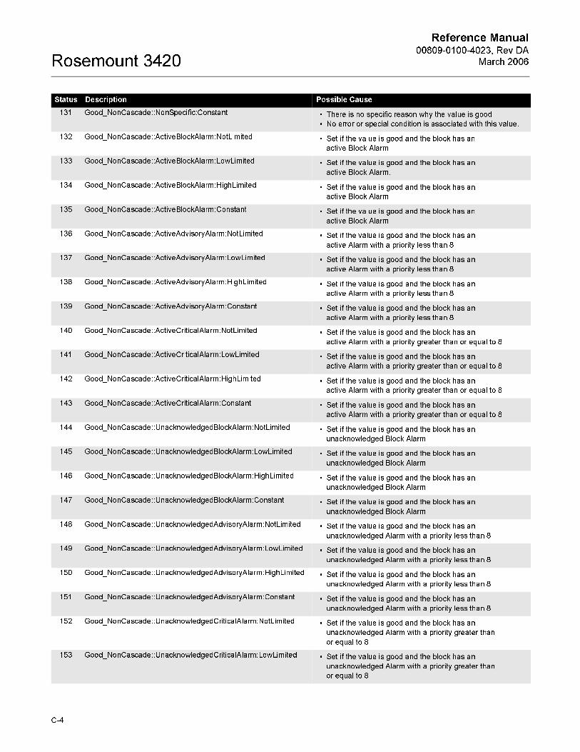
Reference Manual00809-0100-4023, Rev DA
March 2006Rosemount 3420
131 Good_NonCascade::NonSpecific:Constant • There is no specific reason why the value is good
• No error or special condition is associated with this value.
132 Good_NonCascade::ActiveBlockAlarm:NotLimited • Set if the value is good and the block has an
active Block Alarm
133 Good_NonCascade::ActiveBlockAlarm:LowLimited • Set if the value is good and the block has an
active Block Alarm.
134 Good_NonCascade::ActiveBlockAlarm:HighLimited • Set if the value is good and the block has an
active Block Alarm
135 Good_NonCascade::ActiveBlockAlarm:Constant • Set if the value is good and the block has an
active Block Alarm
136 Good_NonCascade::ActiveAdvisoryAlarm:NotLimited • Set if the value is good and the block has an
active Alarm with a priority less than 8
137 Good_NonCascade::ActiveAdvisoryAlarm:LowLimited • Set if the value is good and the block has an
active Alarm with a priority less than 8
138 Good_NonCascade::ActiveAdvisoryAlarm:HighLimited • Set if the value is good and the block has an
active Alarm with a priority less than 8
139 Good_NonCascade::ActiveAdvisoryAlarm:Constant • Set if the value is good and the block has an
active Alarm with a priority less than 8
140 Good_NonCascade::ActiveCriticalAlarm:NotLimited • Set if the value is good and the block has an
active Alarm with a priority greater than or equal to 8
141 Good_NonCascade::ActiveCriticalAlarm:LowLimited • Set if the value is good and the block has an
active Alarm with a priority greater than or equal to 8
142 Good_NonCascade::ActiveCriticalAlarm:HighLimited • Set if the value is good and the block has an
active Alarm with a priority greater than or equal to 8
143 Good_NonCascade::ActiveCriticalAlarm:Constant • Set if the value is good and the block has an
active Alarm with a priority greater than or equal to 8
144 Good_NonCascade::UnacknowledgedBlockAlarm:NotLimited • Set if the value is good and the block has an
unacknowledged Block Alarm
145 Good_NonCascade::UnacknowledgedBlockAlarm:LowLimited • Set if the value is good and the block has an
unacknowledged Block Alarm
146 Good_NonCascade::UnacknowledgedBlockAlarm:HighLimited • Set if the value is good and the block has an
unacknowledged Block Alarm
147 Good_NonCascade::UnacknowledgedBlockAlarm:Constant • Set if the value is good and the block has an
unacknowledged Block Alarm
148 Good_NonCascade::UnacknowledgedAdvisoryAlarm:NotLimited • Set if the value is good and the block has an
unacknowledged Alarm with a priority less than 8
149 Good_NonCascade::UnacknowledgedAdvisoryAlarm:LowLimited • Set if the value is good and the block has an
unacknowledged Alarm with a priority less than 8
150 Good_NonCascade::UnacknowledgedAdvisoryAlarm:HighLimited • Set if the value is good and the block has an
unacknowledged Alarm with a priority less than 8
151 Good_NonCascade::UnacknowledgedAdvisoryAlarm:Constant • Set if the value is good and the block has an
unacknowledged Alarm with a priority less than 8
152 Good_NonCascade::UnacknowledgedCriticalAlarm:NotLimited • Set if the value is good and the block has an
unacknowledged Alarm with a priority greater than
or equal to 8
153 Good_NonCascade::UnacknowledgedCriticalAlarm:LowLimited • Set if the value is good and the block has an
unacknowledged Alarm with a priority greater than
or equal to 8
Status Description Possible Cause
C-4

Reference Manual 00809-0100-4023, Rev DA
March 2006 Rosemount 3420
154 Good_NonCascade::UnacknowledgedCriticalAlarm:HighLimited • Set if the value is good and the block has an
unacknowledged Alarm with a priority greater than
or equal to 8
155 Good_NonCascade::UnacknowledgedCriticalAlarm:Constant • Set if the value is good and the block has an
unacknowledged Alarm with a priority greater than
or equal to 8
192 Good_Cascade::NonSpecific:NotLimited • There is no reason why the value is good
• No error or special condition is associated with this value
193 Good_Cascade::NonSpecific:LowLimited • There is no reason why the value is good
• No error or special condition is associated with this value
194 Good_Cascade::NonSpecific:HighLimited • There is no reason why the value is good
• No error or special condition is associated with this value.
195 Good_Cascade::NonSpecific:Constant • There is no reason why the value is good. No error or special
condition is associated with this value
196 Good_Cascade::InitializationAcknowledge:NotLimited • The value is an initialized value from a source (cascade
input, remote-cascade-in, and remote-output in parameters)
197 Good_Cascade::InitializationAcknowledge:LowLimited • The value is an initialized value from a source (cascade
input, remote-cascade-in, and remote-output in parameters)
198 Good_Cascade::InitializationAcknowledge:HighLimited • The value is an initialized value from a source (cascade
input, remote-cascade-in, and remote-output in parameters)
199 Good_Cascade::InitializationAcknowledge:Constant • The value is an initialized value from a source (cascade
input, remote-cascade-in, and remote-output in parameters)
200 Good_Cascade::InitializationRequest:NotLimited • The value is an initialization value for a source (back
calculation input parameter), because the lower loop is
broken or in the wrong mode
201 Good_Cascade::InitializationRequest:LowLimited • The value is an initialization value for a source (back
calculation input parameter), because the lower loop is
broken or in the wrong mode
202 Good_Cascade::InitializationRequest:HighLimited • The value is an initialization value for a source (back
calculation input parameter), because the lower loop is
broken or in the wrong mode
203 Good_Cascade::InitializationRequest:Constant • The value is an initialization value for a source (back
calculation input parameter), because the lower loop is
broken or in the wrong mode
204 Good_Cascade::NotInvited:NotLimited • The value is from a block which does not have a target mode
that would use this input
205 Good_Cascade::NotInvited:LowLimited • The value is from a block which does not have a target mode
that would use this input
206 Good_Cascade::NotInvited:HighLimited • The value is from a block which does not have a target mode
that would use this input
207 Good_Cascade::NotInvited:Constant • The value is from a block which does not have a target mode
that would use this input
208 Good_Cascade::NotSelected:NotLimited • The value is from a Control Selector which has not selected
the corresponding input
• This tells the upper block to limit in one direction,
not to initialize
209 Good_Cascade::NotSelected:LowLimited • The value is from a Control Selector which has not selected
the corresponding input
• This tells the upper block to limit in one direction,
not to initialize
Status Description Possible Cause
C-5

Reference Manual00809-0100-4023, Rev DA
March 2006Rosemount 3420
210 Good_Cascade::NotSelected:HighLimited • The value is from a Control Selector which has not selected
the corresponding input
• This tells the upper block to limit in one direction,
not to initialize
211 Good_Cascade::NotSelected:Constant • The value is from a Control Selector which has not selected
the corresponding input
• This tells the upper block to limit in one direction,
not to initialize
212 Good_Cascade::DoNotSelect:NotLimited • The value is from a block which should not be selected by a
control selector block, due to conditions in or above the block
213 Good_Cascade::DoNotSelect:LowLimited • The value is from a block which should not be selected by a
control selector block, due to conditions in or above the block
214 Good_Cascade::DoNotSelect:HighLimited • The value is from a block which should not be selected by a
control selector block, due to conditions in or above the block
215 Good_Cascade::DoNotSelect:Constant • The value is from a block which should not be selected by a
control selector block, due to conditions in or above the block
216 Good_Cascade::LocalOverride:NotLimited • The value is from a block that has been overriden by a
local key switch
• This also implies Not Invited
217 Good_Cascade::LocalOverride:LowLimited • The value is from a block that has been overriden by a
local key switch
• This also implies Not Invited
218 Good_Cascade::LocalOverride:HighLimited • The value is from a block that has been overriden by a
local key switch
• This also implies Not Invited
219 Good_Cascade::LocalOverride:Constant • The value is from a block that has been overriden by a
local key switch
• This also implies Not Invited
220 Good_Cascade::FaultStateActive:NotLimited • The value is from a block that has FAULT-STATE active
• This also implies Not Invited
221 Good_Cascade::FaultStateActive:LowLimited • The value is from a block that has FAULT-STATE active
• This also implies Not Invited
222 Good_Cascade::FaultStateActive:HighLimited • The value is from a block that has FAULT-STATE active
• This also implies Not Invited
223 Good_Cascade::FaultStateActive:Constant • The value is from a block that has FAULT-STATE active
• This also implies Not Invited
224 Good_Cascade::InitiateFaultState:NotLimited • The value is from a block that wants its downstream output
block to go to Fault State
225 Good_Cascade::InitiateFaultState:LowLimited • The value is from a block that wants its downstream output
block to go to Fault State
226 Good_Cascade::InitiateFaultState:HighLimited • The value is from a block that wants its downstream output
block to go to Fault State
227 Good_Cascade::InitiateFaultState:Constant • The value is from a block that wants its downstream output
block to go to Fault State
Status Description Possible Cause
C-6

Reference Manual 00809-0100-4023, Rev DA
March 2006 Rosemount 3420
Appendix D Modbus Configuration in Honeywell® TDC APM/HPM
Refer to the Honeywell Manual OP01-501 APM/HPM Serial Interface Optionsfor information on Modbus Configuration.
The Rosemount 3420 can address registers up to 65535. TDC requires that
you use specific register ranges to read floating point numbers. The
Honeywell manual contains the following information:
“Floating point format data for the address range 20001 to 29999 is returned in standard IEEE floating point format except that the low and
high words are swapped. This format is appropriate for the Modicon 984
Programmable Logic Controller (PLC).”
This requires setting the swapped floating point option in the Rosemount 3420
on the Modbus Setup Page.
www.rosemount.com

Reference Manual00809-0100-4023, Rev DA
March 2006Rosemount 3420
Glossary-2

Reference Manual 00809-0100-4023, Rev DA
March 2006 Rosemount 3420
Appendix E Integer Scaling
Integer Scaling . . . . . . . . . . . . . . . . . . . . . . . . . . . . . . . . . . E - 1
Configuring Scaled Integers. . . . . . . . . . . . . . . . . . . . . . . . E - 1
Using Integer Scaling to Define Range Limits . . . . . . . . . E - 3
INTEGER SCALING If you read process variables from integer registers, the 3420 ordinarily
returns a rounded integer, such as 2712 to represent 2711.97 grams per
minute, or 1 to indicate a density of 1.2534 grams per cubic centimeter.
Integer scaling causes the 3420 to return integers, accurate to one part in
65536, representing the measured value of the process variable, such as
50000 to represent a mass flow rate of 50 grams per second. Scaled integers
amplify and linearize small changes in critical process variables.
You can implement integer scaling for the following purposes:
• To offset negative values such as subzero temperatures or reverse flow
rates, so they can be read as positive integers.
• To increase output resolution of values such as density, temperature,
pressure, or low flow rates.
CONFIGURING SCALED INTEGERS
If you configure integer scaling for more than one process variable, the same
maximum integer applies to all scaled process variables. Each scaled
process variable can have its own offset and scale factor.
To determine a scaled integer proportional to the measured value of a
process variable, the 3420 uses a variation of the linear equation. The
equation represents a linear correction of the measured value:
y = Ax - (B - 32768)
Where:
y = Scaled integer returned by the3420
A = Gain for scaled integer values
x = Measured value of the process variable
B = Offset for scaled integer values
www.rosemount.com

Reference Manual00809-0100-4023, Rev DA
March 2006Rosemount 3420
To configure integer scaling of process variables, follow these steps:
1. Select a maximum integer and write its value in the appropriatefield
on the Setup>Modbus>Communications page. If you are using
global scale factors and offsets enter these on the same page.
Otherwise:
2. Derive a gain for each desired process variable and write the values
to the appropriate I/O point.
3. Derive an offset for each desired process variable and write the
values to the appropriate I/O point.
Step 1: Determine Maximum Integer
A scaled integer is the value of y in the equation presented above. The
maximum integer is the highest integer proportional to a measured value of a
process variable. The default maximum integer is 65534.
KEY TO USING MAXIMUM INTEGERS
If integer scaling applies to more than one process variable, all scales must share the same maximum integer, but may have different offsets and scale
factors.
You can program a maximum integer below the default maximum integer. The
maximum integer selected may be determined by the Modbus host’s
capabilities. For example, the Honeywell control system allows transmission
of integer values from 0 to 9999 or from 0 to 4096.
The overflow integer is defined as the maximum integer plus 1. Therefore, if
the maximum integer is 1000, the overflow integer is 1001. If the default
maximum integer is used (65534), the default overflow integer is 65535.
The 3420 returns the overflow integer if the measured value of a process
variable derives an integer higher than the maximum integer. The transmitter
also returns the overflow integer if any of the following alarm conditions exists:
• Sensor failure
• Input overrange
• Density outside sensor limits
• Temperature outside sensor limits
• Transmitter electronics failure
Step 2: Determine the Gain (Slope)
The scale factor is the value of A in the equation above. The scale factor
equals the linear slope of the integers, which are proportional to measured
values of the process variable. The scale factor therefore is a ratio that compares the change in the measured value to the proportional change in
value of the scaled integers.
Step 3: Determine Offset The offset for scaled integers is the value of B in the equation above. The intercept, or the offset minus 32768, equals the value of the process variable
that is represented by a scaled integer value of 0. The offset enables scaled
integers, which always have positive values, to represent negative values
such as a subzero temperature or a reverse flow rate.
Since B (the offset) always has a value from 0 to 65534, the3420 uses the
following equation to derive a positive or negative intercept:
E-2

Reference Manual 00809-0100-4023, Rev DA
March 2006 Rosemount 3420
Intercept = Offset - 32768
• The maximum negative intercept is -32768, where the offset = 0.
• The intercept is 0, where the offset = 32768
• The maximum positive intercept is 32767, where the offset = 65535
So, although you write the offset as an integer from 0 to 65535, the process
variable can have a value less than, equal to, or greater than 0.
USING INTEGER SCALING TO DEFINE RANGE LIMITS
The maximum integer, offsets, and scale factors establish programmable
limits on process variables. Establish an integer scale for programmable limits on process variables according to either of the two methods described below.
Method 1
Follow these steps while referring to Example 1 and Example 2.
1. Use the following equations to set up scaled integer limits
corresponding to lower and upper range values of the process variable.
Where:
x1 = Lower range value
x2 = Upper range value
y1 = Maximum integer
y2 = An integer (usually 0) with lower than the maximum integer
2. Write the integer value of y (the maximum integer) to the appropriate
configuration entry field.
3. Write the integer value of A (the gain) to the appropriate configuration
entry field.
4. Write the integer value of B (the offset) to the appropriate
configuration entry field.
Gainy2 y1–
x2 x1–-----------------=
Offset Gain x1×( ) y2– 32768+=
E-3

Reference Manual00809-0100-4023, Rev DA
March 2006Rosemount 3420
Example 1 The 3420 FIM is connected to a Honeywell TDC3000 control system using a
PLC Gateway. The control system engineer sets up an analog input point to
bring in volume flow, which enables use of flow limit alarms in the control
system. On the control system, an analog input point has limits of 0 to 4095,
with any input greater than 4095 indicating a “bad” process variable. The
lower range limit is -100 barrels/day. The upper range limit is 300 barrels/day.
1. Set up the maximum integer, if necessary.
2. Set up scaled integer limits corresponding to the lower and upper
range values.
3. Determine the gain:
4. Determine the offset:
5. The calculated scale factor of 10.2375 was rounded down to 10, so
the actual transmitter range will slightly exceed the desired range of
-100 to 300. To allow proper scaling of the analog input point data by
the Honeywell control system, calculate the actual transmitter range
corresponding to scaled integer values of 0 and 4095:
Lower range value
Upper range value
Example 2 Scale the mass flow rate so 0 represents -100 pounds/minute (lb/min) and
30,000 represents 200 lb/min.
Scale factor:
y2 y1–
x2 x1–-----------------=
4095 0–300 100–( )–----------------------------------=
4095400
-------------=
10.2375=
Gain x1×( ) y1– 32768+=
10 100–( )×[ ] 0– 32768+=
1000– 32768+=
31768=
x1 100–==
y2 y1–
Gain-----------------= x1+
4095 0–10
---------------------- 100–=
309.5=
y2 y1–
x2 x1–-----------------=
30000 0–200 100–( )–----------------------------------=
30000300
----------------=
100=
E-4

Reference Manual 00809-0100-4023, Rev DA
March 2006 Rosemount 3420
Offset:
Method 2
Choose a maximum integer equal to or less than 65534, then using the linear
equation presented to solve for A (the scale factor) and B (the offset), as
shown in Example 3.
1. Write the integer value of y (the maximum integer) to the appropriate
I/O point
2. Write the integer value of A (the scale factor) to the appropriate I/O
point
3. Write the integer value of B (the offset) to the appropriate I/O point
Example 3 The mass flow rate needs to remain between 30 and 40 grams per minute
(g/min). Scale the mass flow rate so 0 represents a flow rate of 40.000 g/min,
and 10,001 represents a flow rate greater than 40.000 g/min.
Solve for A:
Solve for B:
• The maximum integer is 10,000. If the mass flow rate exceeds 40.000
g/min, the transmitter returns the integer 10,001.
• The scale factor is 1000. A change of 1 in the value of the integers
represents a change of 0.001 g/min in the mass flow rate.
• The offset is 62,768. If the mass flow rate drops to 30.000 g/min, the
transmitter returns a 0.
Gain x1×( ) y2– 32768+=
100 100–( )–[ ] 0– 32768+=
22768=
10000 A 40( ) B(– 32768 )–=
0 A 30( ) B(– 32768 )–=
10000 A 10( )=
A 1000010
----------------=
A 1000=
10000 1000 40( ) B(– 32768 )–=
10000 40000 B(– 32768 )–=
10000 40000 32768 B–+=
B 62768=
E-5

Reference Manual00809-0100-4023, Rev DA
March 2006Rosemount 3420
E-6

Reference Manual 00809-0100-4023, Rev DA
March 2006 Rosemount 3420
Appendix F AMS™ Suite: Intelligent Device Manager with Rosemount 3420
™
BENEFITS AMS Suite provides a comprehensive and integrated family of predictiveand proactive maintenance applications including a common interface to device diagnostics. AMS™ Suite: Intelligent Device Manager provides support
for more than 141 FOUNDATION™ fieldbus devices from 33 manufacturers, and
267 HART® devices from 39 manufacturers. Its comprehensive set of analysis
and reporting tools presents a single application for predictive diagnostics,
documentation, calibration management, and device configuration.
When used in conjunction with the Rosemount 3420 Fieldbus Interface
Module, Intelligent Device Manager provides a powerful tool for complete
management of a plant’s valuable instrument and valve assets. Besides
providing a user-friendly interface for configuring, diagnosing, and calibrating
a plant’s fieldbus devices, Intelligent Device Manager provides a complete
historical Audit Trail of all events associated with these activities. The Alert
Monitor within Intelligent Device Manager quickly alerts the user of diagnostic conditions associated with the fieldbus devices connected to the 3420.
Calibration management of these devices is easily handled by the Calibration
Assistant SNAP-ON™ available with AMS™ Suite Intelligent Device Manager.
The AMS™ Suite: ValveLink® SNAP-ON™ for the FIELDVUE® Digital Valve
Controller provides advanced diagnostics on complete control valve
assemblies.
FOUNDATION™ Fieldbus HSE Network Displayed in AMS Device Manager with Rosemount 3420 Connected
www.rosemount.com

Reference Manual00809-0100-4023, Rev DA
March 2006Rosemount 3420
NETWORK CONFIGURATION FOR ROSEMOUNT 3420
Establishing a connection between Intelligent Device Manager and the 3420
is easy. The following steps are required.
1. Stop Intelligent Device Manager if it is running
2. Select Start | Programs | AMS Device Manager | Network
Configuration from the Windows Task Bar.
3. Click Add.
4. Select FF HSE Network from the list of networks in the Select
Network Component Type dialog box.
5. Click Install.
6. Enter a name for the HSE network. This will be the name that will
appear at the top of the 3420’s branch in AMS Device Manager.
7. Click NEXT
8. Select the Primary HSE NIC Address. This is the IP address of the
NIC card to which the 3420 (s) are connected.
9. Check the box that says “Enable Processing and
acknowledgement of fieldbus alerts”
10. Click FINISH
11. Click Close
When AMS Device Manager is restarted, the FOUNDATION™ Fieldbus HSE
Network will now show up in both the Explorer and Device Connection view.
Right click on the FOUNDATION™ Fieldbus HSE Network icon and request
Rebuild Hierarchy. Next, right click on the 3420 icon and request a Scan of
all devices. When the scan is compete, the user can expand the interface by
selecting the plus sign on the 3420 icon and the fieldbus segment desired. A
list of all devices on the segment will be displayed.
USING THE
FOUNDATION™ FIELDBUS HSE SYSTEM INTERFACE IN AMS
DEVICE MANAGER
The FOUNDATION™ Fieldbus HSE System Interface lets you use AMS Device
Manager to view and configure fieldbus devices connected to the 3420
Fieldbus Interface Module.
The 3420 Fieldbus Interface Module is connected to the AMS Device
Manager PC through an Ethernet card. (a dedicated Ethernet card is
recommended). AMS Device Manager supports up to 16 3420’s in one
FOUNDATION™ Fieldbus HSE Network. Communications with the 3420’s on
multiple Ethernet segments is not supported.
A fieldbus device must be commissioned in order for AMS Device manager to
communicate with it.
Foundation Fieldbus HSE Network Hierarchy
A FOUNDATION™ Fieldbus HSE network is represented by its icon, which is at
the top of the network hierarchy in Device Connection View or Device
Explorer View. The second level of the hierarchy displays the HSE linking
devices. The icon displayed for an HSE linking device is provided by the
manufacturer.
The third level of hierarchy displays the fieldbus H1 links. The fourth level of
the hierarchy displays the fieldbus devices. The icons within the HSE network
have context menus from which you can perform various AMS Device
Manager and device functions.
F-2

Reference Manual 00809-0100-4023, Rev DA
March 2006 Rosemount 3420
AMS Tags When a device is added to AMS Device Manager, a unique AMS Tag is
automatically assigned to the device. For FOUNDATION™ Fieldbus HSE
devices, the AMS tag defaults to the fieldbus physical device (PD) tag. If that
tag already exists in the database, a suffix is added to the tag name to make it unique.
THE 3420 WEB
BROWSER AND AMS DEVICE MANAGER
The 3420 Web Browser described elsewhere in the manual provides an
excellent complement to the functionality provided by AMS Device Manager.
Although all fieldbus device data is accessible via the 3420 Web browser,
AMS Device Manager provides the best way to configure a device’s Resource
and Transducer Blocks. AMS Device Manager also provides an excellent way
to view a device’s diagnostic alert conditions using Alert Monitor. On the other
hand, configuring a device’s Function Blocks such as Analog Input Blocks,
PID Blocks, etc. should be handled by the 3420 Web Browser. This includes
the linking of these blocks into “control in the field” control applications.
The following chart indicates what functions are best performed in the 3420 Web Browser and which functions are best performed by the AMS Device
Manager when dealing with a typical transmitter such as a Rosemount 3051S
pressure transmitter.
Common Functions Performed by AMS Device Manager and 3420 Web Browser
LAUNCHING THE 3420
WEB BROWSER FROM AMS DEVICE MANAGER
The 3420 Web Browser is easily launched by right clicking on the 3420 Icon
under the FOUNDATION™ Fieldbus HSE System Interface branch and selecting
the “Launch 3420 Setup Utility” entry in the context menu. The first time the
Web Browser is launched, it will be necessary to enter the User Name and
Password. The default User Name is admin.
User Function AMS Device Manager 3420 Web Browser
Configuring a Device’s Resource Block X Alternate
Configuring a Device’s Transducer Block X Alternate
Setting up a Device’s Analog Input Block
(including Transducer Scale, I/O Type, etc.)X
Configuring a Control Strategy in a Fieldbus
Device (i.e. PID, etc.)X
Running a Setup or Calibration Procedure (i.e.
method) for a DeviceX
Monitoring PlantWeb Alerts X
Viewing Detailed Device Status X Alternate
Documenting All Changes Made to a device
(i.e. Audit Trail)X
Calibrating a Device X
Keeping Track of Documentation, Notes, and
Help Related to a DeviceX
F-3

Reference Manual00809-0100-4023, Rev DA
March 2006Rosemount 3420
The default Password is fieveladmin. It is not necessary to enter the User
Name and Password if the “remember password” box is selected. The use
and functionality of the 3420 Web Browser is described elsewhere in this
manual. When the user is finished with the Web Browser, the browser
window merely needs to be closed and the user will be returned to the
previous AMS Device Manager view.
Using AMS Device Manager’s Alert Monitor with the Rosemont 3420
The Alert Monitor in AMS Device Manager provides a powerful means to
monitor device alerts reported from the fieldbus devices connected to the
3420. When an alert is reported, the “alarm bell” in the lower corner of the
AMS Device Manager screen is lit and the alert shows up in the Alert Monitor
window. By right clicking a specific alert, a status screen is displayed identifying the specific alert conditions. By dragging the “?” symbol onto this
alert, additional information about the specific alert can be obtained.
When the alert condition is corrected, it disappears from the Alert Monitor
screen. These device alerts are also captured and stored in the Audit Trail.
AMS Alert Monitor displays PlantWeb Alerts as they happen
F-4

Reference Manual 00809-0100-4023, Rev DA
March 2006 Rosemount 3420
Detailed status information can be called up from AMS Alert Monitor
In order for device alerts to be reported to the Alert Monitor from the 3420,
some setup is required. The following is a list of setup requirements to ensure
correct operation of Alert Monitor:
1. When performing the Network Configuration for AMS Device
Manager, check the “Enable processing and acknowledgement of Fieldbus Alerts” box when setting up the fieldbus HSE Network as
described above.
2. Some devices allow specific device alerts to be enable or disabled. In
these cases, make sure the alerts are enabled. These settings are
typically in the device’s Transducer Block and can be changed via
AMS Device Manager.
3. Some devices allow a device alert to be suppressed. This is different
than disabling the alert. Make sure the alert is not suppressed. This
setting it typically in the device’s Resource Block.
4. For a device to have its alerts show up in Alert Monitor, it must be in
the AMS Device Manager Plant Database. Make sure the fieldbus
device connected to the 3420 has been placed in the Plant Database. This is done be “dragging” the device shown under the 3420 to a
folder in the Plant Database.
5. For a device to show up in Alert Monitor, it must be include in the Alert
Monitor List. This is done using the following steps:
a.) Select CONFIGURE from the Alert Monitor Window
b.) Select ADD from the Device Monitor List
c.) Select the device(s) to be added and select OK
d.) Select OK again
F-5

Reference Manual00809-0100-4023, Rev DA
March 2006Rosemount 3420
6. For an alert to show up in Alert Monitor, it is necessary that the
Device Description for that device be available in the 3420. The
method for doing this is described under the “Advanced” subsection
in the Section labeled Fieldbus Field Devices earlier in this manual.
Usually this is not necessary unless the device involved is not a
commonly used fieldbus device.
7. For a device to show up in the Alert Monitor, it is necessary that the
“Reports” option be enabled. For Rosemount devices, this field is
found under the “Options” tab in the Resource Block.
8. Finally, it is necessary that a device connected to the 3420 change
from the normal to alert state for it to show up in the Alert Monitor. If
the device is already in the alert state when the device is added to the
Alert Monitor List, it will not show up until it transitions into the alert
state again.
F-6

Reference Manual 00809-0100-4023, Rev DA
March 2006 Rosemount 3420
Appendix G CSI 9120 Machinery Health Transmitter
PURPOSE OF THE CSI 9210 APPENDIX
The purpose of this appendix is to provide pertinent details needed to use the
Rosemount 3420 in conjunction with the CSI 9120 Machinery Health Transmitter. This appendix focuses primarily on the PlantWeb Alert
configuration and the AI and MAI function block configuration. The CSI 9210
transducer block configuration details are contained in the CSI 9210 user
manual and the user is encouraged to consult this separate manual for the
explanation of these details as they are not contained in this appendix to the
3420 user manual.
INTRODUCTION The CSI 9210 Machinery Health Transmitter is a four-wire, field mountable,
intelligent device that tightly integrates machinery health analysis into the
process automation environment. Each device monitors a single machine
train consisting of one AC induction motor coupled to one centrifugal pump.
Analysis results are delivered as:
• FOUNDATION™ Fieldbus block alerts
• Machinery Health Values to FOUNDATION™ Fieldbus-capable process
automation systems via Analog Input function blocks.
The CSI 9210 collects data from various sensor inputs and assesses the health of the motor-pump machine train. This assessment is based on an
analysis engine that has been specifically optimized and embedded into the
device for the particular machine train.
REV CA\CSI\9210_PHOTO.TIF
www.rosemount.com

Reference Manual00809-0100-4023, Rev DA
March 2006Rosemount 3420
Motor-pump combinations are the backbone of most industries. The
processes that are being driven by these pumps are the life blood of the plant.
Unfortunately, many of these mechanical assets contribute to higher than
desired maintenance costs and are often responsible for the majority of
unplanned process downtime. The CSI 9210 provides an optimized solution
for easy device implementation as the data collection logic and the data
analysis logic are factory configured. The data collection logic and the
analysis logic are based on the specific needs of motor-pump combinations
typically found in process industries.
SCOPE This section covers the configuration details needed to configure and
commission this device using the Rosemount 3420 Fieldbus Interface
Module.
Block Configuration Ensure that all of the resource, transducer, and function blocks are set up to
operate properly.
For the fieldbus block setup, select Setup>Fieldbus>Blocks to ensure all of
the blocks are enabled. Then, to ensure the alarms are enabled, check the
alarms box for Resource 1000.
REV CA\CSI\BLOCK_CONFIG_1.TIF
REV CA\CSI\BLOCK_CONFIG_2.TIF
G-2
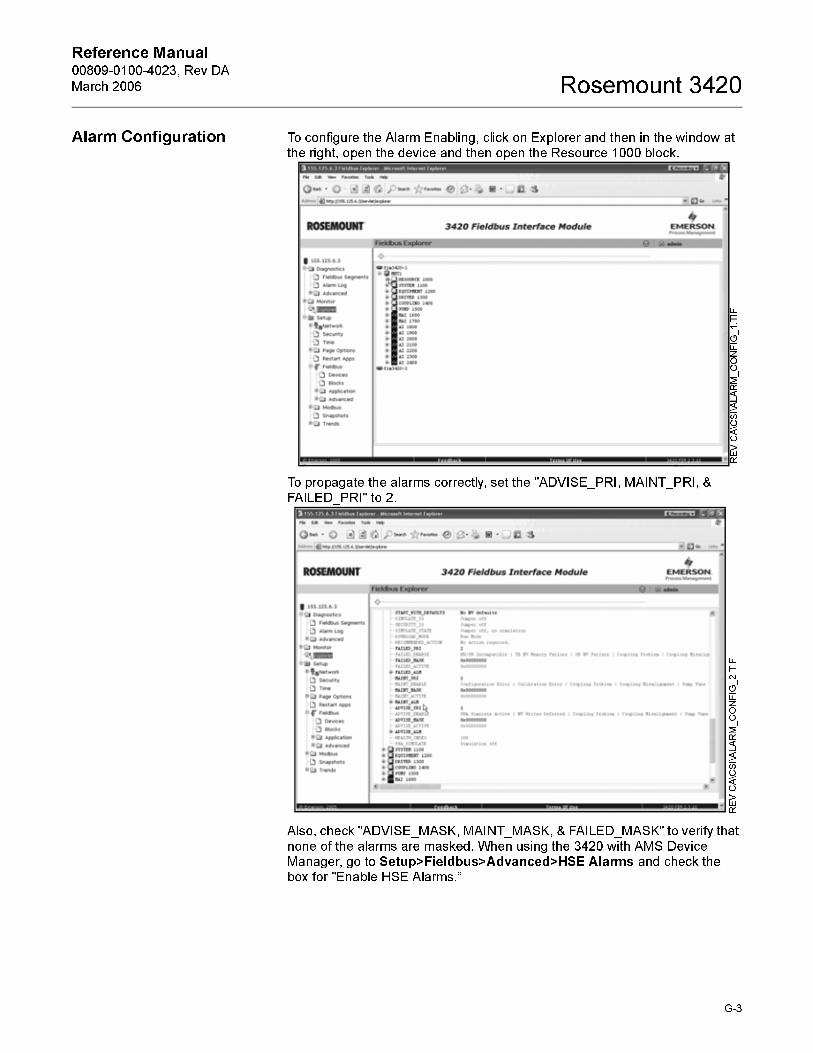
Reference Manual 00809-0100-4023, Rev DA
March 2006 Rosemount 3420
Alarm Configuration To configure the Alarm Enabling, click on Explorer and then in the window at
the right, open the device and then open the Resource 1000 block.
To propagate the alarms correctly, set the "ADVISE_PRI, MAINT_PRI, &
FAILED_PRI" to 2.
Also, check "ADVISE_MASK, MAINT_MASK, & FAILED_MASK" to verify that
none of the alarms are masked. When using the 3420 with AMS Device
Manager, go to Setup>Fieldbus>Advanced>HSE Alarms and check the
box for "Enable HSE Alarms.”
REV CA\CSI\ALARM_CONFIG_1.TIF
REV CA\CSI\ALARM_CONFIG_2.TIF
G-3

Reference Manual00809-0100-4023, Rev DA
March 2006Rosemount 3420
If the 3420 will not be used with AMS Device Manager, uncheck this box to
put the 3420 in the standalone mode. The change will need to be submitted
and then the application will need to be restarted.
Point Pages Configuration - MAI Blocks
To configure the 3420 web page for viewing the process values produced by
the CSI 9210’s MAI function blocks, click on Setup, Page Options, and then
Point Pages.
REV CA\CSI\HSE.TIF
REV CA\CSI\POINT_PAGES_MAI.TIF
G-4

Reference Manual 00809-0100-4023, Rev DA
March 2006 Rosemount 3420
Enter "9210-MAI" for the name of the point page. Click New Entry at the
bottom of the page. Next, click on the browse button under the point name.
Select the output you want to monitor and then go into edit mode in order to
set-up the points.
REV CA\CSI\9210_MAI_1.TIF
REV CA\CSI\9210_MAI_2.TIF
G-5

Reference Manual00809-0100-4023, Rev DA
March 2006Rosemount 3420
On this set-up page, type in the desired names for each of the points. The
recommended names are:
MAI1600 out_1 - Overall health
out_2 - Motor health
out_3 - Coupling health
out_4 - Pump health
MAI1700 out_1 - Ambient temp
out_2 - Skin temp
out_3 - Aux1
out_4 - Aux2
out_5 - Term panel temp
out_6 - Internal temp
Click on submit to save the page.
Point Pages
Configuration-AI blocks
To set-up the 3420’s web page to view the CSI 9210’s AI function block
values, click on Setup>Page Options>Point Pages. Enter "9210-AI" for the
name of the point page and click New Entry at the bottom of the page.
Click on the browse button under the point name and select the output that is
to be monitored.
Set the following values:
AI1800.out - Speed
AI1900.out - Overall Health
AI2000.out - Motor Health
AI2100.out - Coupling Health
AI2200.out - Pump Health
REV CA\CSI\POINT_PAGES_AI.TIF
G-6
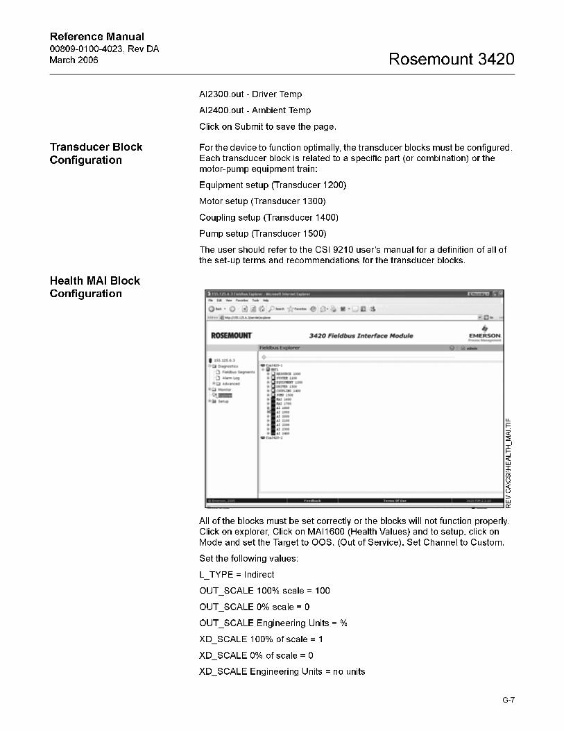
Reference Manual 00809-0100-4023, Rev DA
March 2006 Rosemount 3420
AI2300.out - Driver Temp
AI2400.out - Ambient Temp
Click on Submit to save the page.
Transducer Block
Configuration
For the device to function optimally, the transducer blocks must be configured.
Each transducer block is related to a specific part (or combination) or the
motor-pump equipment train:
Equipment setup (Transducer 1200)
Motor setup (Transducer 1300)
Coupling setup (Transducer 1400)
Pump setup (Transducer 1500)
The user should refer to the CSI 9210 user’s manual for a definition of all of
the set-up terms and recommendations for the transducer blocks.
Health MAI Block Configuration
All of the blocks must be set correctly or the blocks will not function properly.
Click on explorer, Click on MAI1600 (Health Values) and to setup, click on
Mode and set the Target to OOS. (Out of Service). Set Channel to Custom.
Set the following values:
L_TYPE = Indirect
OUT_SCALE 100% scale = 100
OUT_SCALE 0% scale = 0
OUT_SCALE Engineering Units = %
XD_SCALE 100% of scale = 1
XD_SCALE 0% of scale = 0
XD_SCALE Engineering Units = no units
REV CA\CSI\HEALTH_MAI.TIF
G-7

Reference Manual00809-0100-4023, Rev DA
March 2006Rosemount 3420
Channel1 = Overall Health
Channel2 = Motor Health
Channel3 = Coupling Health
Channel4 = Pump Health
Set Target back to Auto
Temperature MAI Block Configuration
Click on the MAI1700 block and to setup, click on Mode and set the Target to
OOS. (Out of Service). Set the Channel to Custom and set the following
parameter values:
L_TYPE = Direct
OUT_SCALE 100% of scale = Maximum Desired Temp
OUT_SCALE 0% of scale = Minimum Desired Temp
OUT_SCALE Engineering Units = °F or °C
XD_SCALE 100% of scale = Maximum Desired Temp
XD_SCALE 0% of scale = Minimum Desired Temp
XD_SCALE Engineering Units = °F or °C
Channel1 = Ambient Temp
Channel2 = Motor Temp
Channel3 = Aux1
Channel4 = Aux2
Channel 5 = Term Panel Temp
Channel6 = Enclosure Temp
After ensuring the values are set correctly, set the Target back to Auto.
Health AI Block Configuration
To configure any one of the four Health AI blocks, first, click on explorer and
then set the following AI block values:
1800 = Current Speed
1900 = Overall Health
2000 = Motor Health
2100 = Coupling Health
2200 = Pump Health
2300 = Driver Temp
2400 = Ambient Temp
Set the Health AI block values:
L_TYPE = Indirect
OUT_SCALE 100% scale = 100
OUT_SCALE 0% scale = 0
OUT_SCALE Engineering Units = %
XD_SCALE 100% of scale = 1
G-8

Reference Manual 00809-0100-4023, Rev DA
March 2006 Rosemount 3420
XD_SCALE 0% of scale = 0
XD_SCALE Engineering Units = no units
Temperature AI Block
Configuration
Set the Temperature AI' block values:
L_TYPE = Direct
XD_SCALE 100% of scale = Maximum Desired Temp
XD_SCALE 0% of scale = Minimum Desired Temp
XD_SCALE Engineering Units = °F or °C
OUT_SCALE – Same as XD_SCALE
Speed AI Block Configuration
Set the Speed AI block values:
L_TYPE = Indirect
OUT_SCALE 100% scale = Maximum RPM (3600)
OUT_SCALE 0% scale = 0
OUT_SCALE Engineering Units = RPM
XD_SCALE 100% of scale = Maximum HZ (60)
XD_SCALE 0% of scale = 0
XD_SCALE. UNITS = Hz
Channel Mapping
The channel mapping should be set to the following values:
Overall Health – Ch1
Motor Health – Ch2
Coupling Health – Ch3
Pump Health – Ch4
REV CA\CSI\CHANNEL_MAPPING.TIF
G-9

Reference Manual00809-0100-4023, Rev DA
March 2006Rosemount 3420
Motor Speed – Ch5
Ambient Temperature – Ch6
Skin Temperature – Ch7
Aux1 Temperature – Ch8
Aux2 Temperature – Ch9
Term Panel Temperature – Ch10
Internal Housing Temperature – Ch11
G-10

Reference Manual 00809-0100-4023, Rev DA
March 2006 Rosemount 3420
Glossary
Networking Definitions . . . . . . . . . . . . . . . . . . . . . . . . . . . . Glossary-1
Fieldbus Definitions . . . . . . . . . . . . . . . . . . . . . . . . . . . . . . Glossary-2
NETWORKING DEFINITIONS Term Definitions
DHCP Dynamic Host Configuration Protocol: Used to configure the
network parameters automatically. This device contains a DHCP
Client to retrieve the network configuration parameters from a
DHCP server on the network.
NTP/SNTP Network or Simple Network Time Protocol: Used to set the system
time. This device contains an NTP client for keeping the system
time synchronized with a network time server.
Domain Name A unique designator on the internet composed of symbols
separated by dots such as: this.domain.com
FTP File Transfer Protocol: A method for transferring files to and from
remote computers on the network.
Host Name A unique designator in a domain associated with the IP address of
a device such as: device.this.domain.com. In that example the
hostname is device.
HTML Hyper Text Markup Language: The file format used to define pages
viewed with a web browser.
HTTP Hyper Text Transfer Protocol: The protocol that defines how a web
server sends and receives data to and from a web browser.
IP Internet Protocol: The protocol that specifies how data is transmitted
over the internet.
Netmask A string of 1's and 0's that mask out or hide the network portion of
an IP address leaving only the host component.
Network The portion of the network that the device resides on.
Broadcast The address that a station can send to that will be received by all
devices on the network.
Gateway The address of the node on the network that serves as an entrance
to other networks.
www.rosemount.com

Reference Manual00809-0100-4023, Rev DA
March 2006Rosemount 3420
FIELDBUS DEFINITIONSTerm Definitions
Terminator A device attached to the end of a communications bus or network to
absorb signals so they do not reflect back.
Resource Block The resource block defines device specific characteristics such as
software revisions, hardware revision and materials of construction.
Transducer Block The transducer block defines device specific input/output
characteristics for function block application purposes. It contains
universal parameters and device specific parameters such as trim
limits, sensor type, sensor serial number and sensor diagnostic
information.
Function Block Function blocks define the capabilities of the high level measurement
and control available in the device. There are many possible function
block capabilities contained in a device such as analog input, discrete
input, discrete output, signal characterizer, arithmetic, integrator, PD or
PID control, input selector or analog output.
Analog Input (AI)
Function Block
Scanned by the Rosemount 3420.
Multiple Analog
Input (MAI) Function
Block
Provides up to 8 variable in one function block, reducing scan times.
Mode Target - The mode requested by the operator
Actual - The current mode of the block which may differ from the
target based on the current operating conditions. The actual mode is
calculated during block execution.
Permitted - The modes allowed by target during operation
Normal - The desired operating mode of the block.
Mode: Out of
Service
In this mode the algorithm of the block is no longer being executed and
any outstanding alarms will be cleared. This is the highest priority
mode.
Mode: Auto In this mode the block algorithm is being executed with new value and
status as well as mode being computed each Macrocycle or execution
of the block
Mode: Manual In this mode the block output is not being calculated although it may
be limited. It is set directly by the operator through an interface device.
Macrocycle The period of execution in which the function block schedule is
defined.
Schedule The rate and relative time which function blocks process their inputs
and generate their outputs. The schedule defines when a function
block is triggered to start execution
Link Master A link master device is a device that is capable of becoming the LAS.
There is a bid procedure that is followed that selects the link master
device with the lowest node address.
Link Active
Schedule Device
The LAS performs five functions:
• Maintains the schedule to send compel data (CD) messages
(DLPDU's) to devices on the network. This is the highest priority
function.
• Sends probe node (PN) messages to unused addresses to detect
new devices added to the link/segment and adds them to the Live
List when found.
• Periodically distributes data link time and link schedule time
• Send pass token (PT) messages to devices to provide them the
opportunity to send unscheduled data.
• Monitor responses to pass token (PT) messages and removes
devices from the Live List when a device fails to use or return the
token.
Device Tag The 32 character name of the device.
Block Tag The 32 character name of the function block.
Parameter Name The name of the function block parameter.
Subparameter Name The name of the function block subparameter.
Glossary-2


Reference Manual00809-0100-4023, Rev DA
March 2006
Emerson Process Management
© 2006 Rosemount Inc. All rights reserved.
¢00809-0100-4023(¤
Rosemount and the Rosemount logotype are registered trademarks of Rosemount, Inc.All other marks are the property of their respective owners.
Emerson Process Management Shared Services LTD.Heath PlaceBognor RegisWest Sussex PO22 9SHEnglandT 44 (1243) 863 121F 44 (1243) 867 554
Emerson Process Management Asia Pacific Private Limited1 Pandan CrescentSingapore 128461T (65) 6777 8211F (65) 6777 0947/65 6777 [email protected]
Rosemount Inc.8200 Market BoulevardChanhassen, MN 55317 USAT (U.S.) 1-800-999-9307T (International) (952) 906-8888F (952) 949-7001
www.rosemount.com