Embed Size (px)
Citation preview
114
Ro
of
Mo
unte
d F
ans
MA
X-T
EM
P C
TH
B-C
TH
T
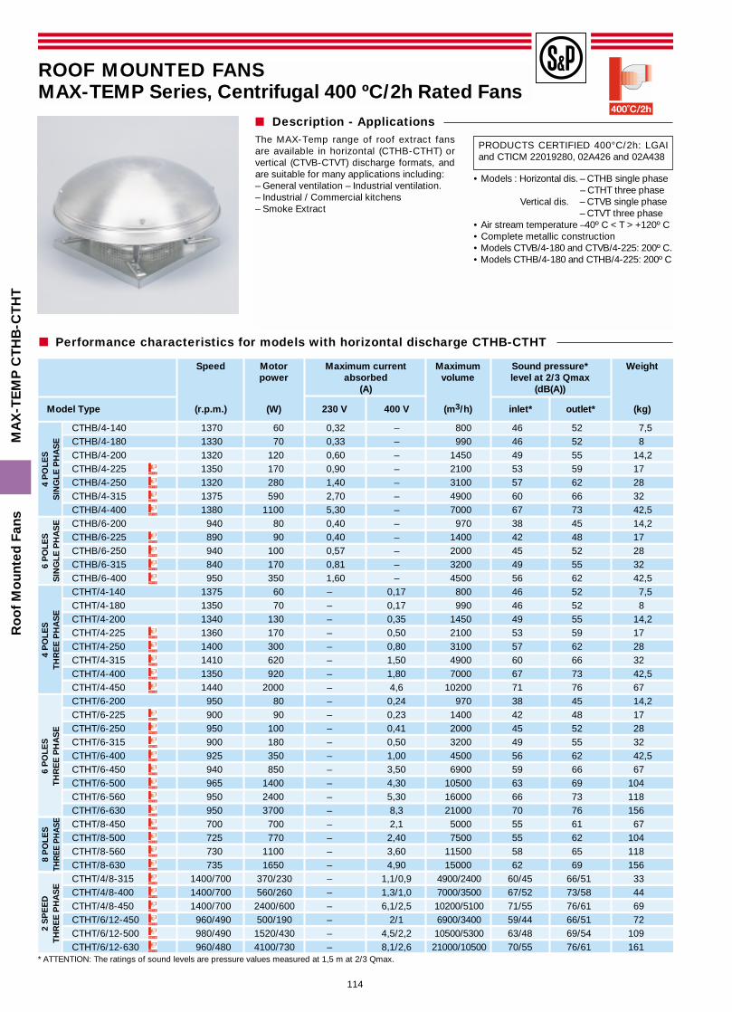
� Description - ApplicationsThe MAX-Temp range of roof extract fansare available in horizontal (CTHB-CTHT) orvertical (CTVB-CTVT) discharge formats, andare suitable for many applications including:– General ventilation – Industrial ventilation.– Industrial / Commercial kitchens– Smoke Extract
• Models : Horizontal dis. – CTHB single phase– CTHT three phase
Vertical dis. – CTVB single phase– CTVT three phase
• Air stream temperature –40º C < T > +120º C• Complete metallic construction• Models CTVB/4-180 and CTVB/4-225: 200º C.• Models CTHB/4-180 and CTHB/4-225: 200º C
ROOF MOUNTED FANSMAX-TEMP Series, Centrifugal 400 ºC/2h Rated Fans
PRODUCTS CERTIFIED 400°C/2h: LGAIand CTICM 22019280, 02A426 and 02A438
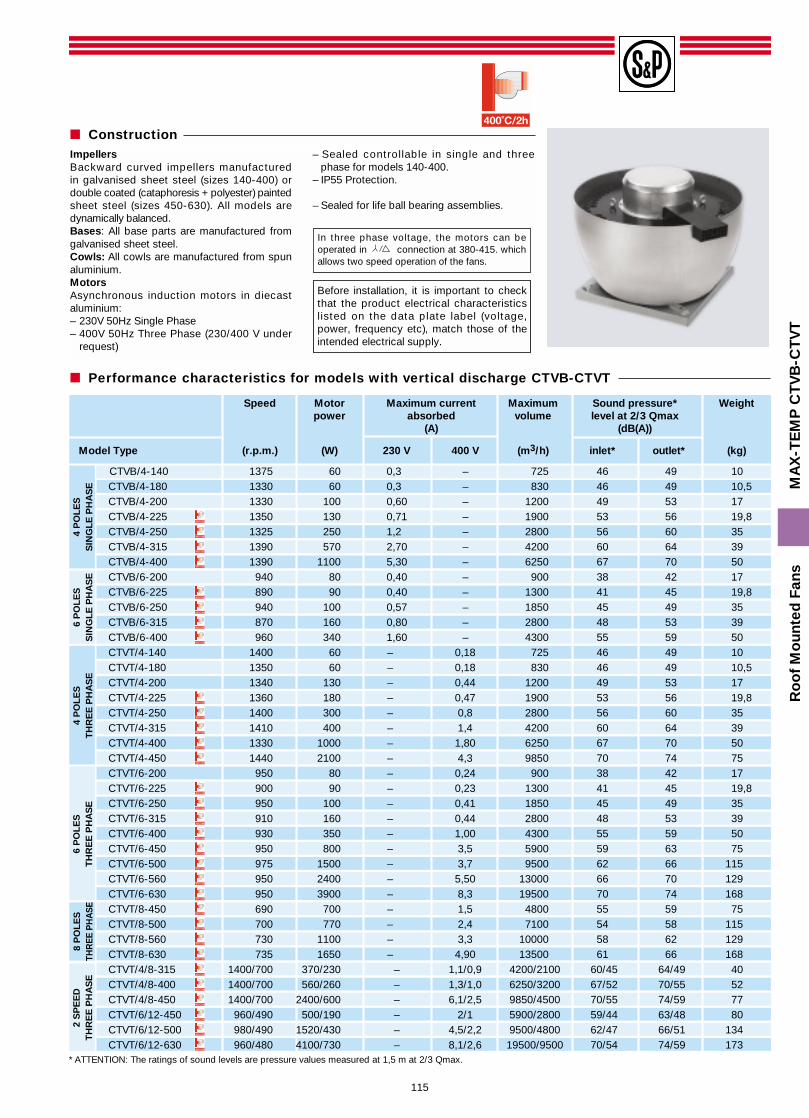
* ATTENTION: The ratings of sound levels are pressure values measured at 1,5 m at 2/3 Qmax.
4 P
OLE
SS
ING
LE P
HA
SE
6 P
OLE
SS
ING
LE P
HA
SE
4 P
OLE
ST
HR
EE
PH
AS
E6
PO
LES
TH
RE
E P
HA
SE
2 S
PE
ED
TH
RE
E P
HA
SE
8 P
OLE
STH
REE
PH
ASE
Performance characteristics for models with horizontal discharge CTHB-CTHT
Speed Motor Maximum current Maximum Sound pressure* Weightpower absorbed volume level at 2/3 Qmax
(A) (dB(A))
Model Type (r.p.m.) (W) 230 V 400 V (m3/h) inlet* outlet* (kg)
CTHB/4-140 1370 60 0,32 – 800 46 52 7,5CTHB/4-180 1330 70 0,33 – 990 46 52 8CTHB/4-200 1320 120 0,60 – 1450 49 55 14,2CTHB/4-225 1350 170 0,90 – 2100 53 59 17CTHB/4-250 1320 280 1,40 – 3100 57 62 28CTHB/4-315 1375 590 2,70 – 4900 60 66 32CTHB/4-400 1380 1100 5,30 – 7000 67 73 42,5CTHB/6-200 940 80 0,40 – 970 38 45 14,2CTHB/6-225 890 90 0,40 – 1400 42 48 17CTHB/6-250 940 100 0,57 – 2000 45 52 28CTHB/6-315 840 170 0,81 – 3200 49 55 32CTHB/6-400 950 350 1,60 – 4500 56 62 42,5CTHT/4-140 1375 60 – 0,17 800 46 52 7,5CTHT/4-180 1350 70 – 0,17 990 46 52 8CTHT/4-200 1340 130 – 0,35 1450 49 55 14,2CTHT/4-225 1360 170 – 0,50 2100 53 59 17CTHT/4-250 1400 300 – 0,80 3100 57 62 28CTHT/4-315 1410 620 – 1,50 4900 60 66 32CTHT/4-400 1350 920 – 1,80 7000 67 73 42,5CTHT/4-450 1440 2000 – 4,6 10200 71 76 67CTHT/6-200 950 80 – 0,24 970 38 45 14,2CTHT/6-225 900 90 – 0,23 1400 42 48 17CTHT/6-250 950 100 – 0,41 2000 45 52 28CTHT/6-315 900 180 – 0,50 3200 49 55 32CTHT/6-400 925 350 – 1,00 4500 56 62 42,5CTHT/6-450 940 850 – 3,50 6900 59 66 67CTHT/6-500 965 1400 – 4,30 10500 63 69 104CTHT/6-560 950 2400 – 5,30 16000 66 73 118CTHT/6-630 950 3700 – 8,3 21000 70 76 156CTHT/8-450 700 700 – 2,1 5000 55 61 67CTHT/8-500 725 770 – 2,40 7500 55 62 104CTHT/8-560 730 1100 – 3,60 11500 58 65 118CTHT/8-630 735 1650 – 4,90 15000 62 69 156CTHT/4/8-315 1400/700 370/230 – 1,1/0,9 4900/2400 60/45 66/51 33CTHT/4/8-400 1400/700 560/260 – 1,3/1,0 7000/3500 67/52 73/58 44CTHT/4/8-450 1400/700 2400/600 – 6,1/2,5 10200/5100 71/55 76/61 69CTHT/6/12-450 960/490 500/190 – 2/1 6900/3400 59/44 66/51 72CTHT/6/12-500 980/490 1520/430 – 4,5/2,2 10500/5300 63/48 69/54 109CTHT/6/12-630 960/480 4100/730 – 8,1/2,6 21000/10500 70/55 76/61 161
115
ImpellersBackward curved impellers manufacturedin galvanised sheet steel (sizes 140-400) ordouble coated (cataphoresis + polyester) paintedsheet steel (sizes 450-630). All models aredynamically balanced.Bases: All base parts are manufactured fromgalvanised sheet steel.Cowls: All cowls are manufactured from spunaluminium.MotorsAsynchronous induction motors in diecastaluminium:– 230V 50Hz Single Phase– 400V 50Hz Three Phase (230/400 V under
request)
– Sealed controllable in single and threephase for models 140-400.
– IP55 Protection.
– Sealed for life ball bearing assemblies.
* ATTENTION: The ratings of sound levels are pressure values measured at 1,5 m at 2/3 Qmax.
Ro
of
Mo
unte
d F
ans
MA
X-T
EM
P C
TV
B-C
TV
T
Speed Motor Maximum current Maximum Sound pressure* Weightpower absorbed volume level at 2/3 Qmax
(A) (dB(A))
Model Type (r.p.m.) (W) 230 V 400 V (m3/h) inlet* outlet* (kg)
CTVB/4-140 1375 60 0,3 – 725 46 49 10CTVB/4-180 1330 60 0,3 – 830 46 49 10,5CTVB/4-200 1330 100 0,60 – 1200 49 53 17CTVB/4-225 1350 130 0,71 – 1900 53 56 19,8CTVB/4-250 1325 250 1,2 – 2800 56 60 35CTVB/4-315 1390 570 2,70 – 4200 60 64 39CTVB/4-400 1390 1100 5,30 – 6250 67 70 50CTVB/6-200 940 80 0,40 – 900 38 42 17CTVB/6-225 890 90 0,40 – 1300 41 45 19,8CTVB/6-250 940 100 0,57 – 1850 45 49 35CTVB/6-315 870 160 0,80 – 2800 48 53 39CTVB/6-400 960 340 1,60 – 4300 55 59 50CTVT/4-140 1400 60 – 0,18 725 46 49 10CTVT/4-180 1350 60 – 0,18 830 46 49 10,5CTVT/4-200 1340 130 – 0,44 1200 49 53 17CTVT/4-225 1360 180 – 0,47 1900 53 56 19,8CTVT/4-250 1400 300 – 0,8 2800 56 60 35CTVT/4-315 1410 400 – 1,4 4200 60 64 39CTVT/4-400 1330 1000 – 1,80 6250 67 70 50CTVT/4-450 1440 2100 – 4,3 9850 70 74 75CTVT/6-200 950 80 – 0,24 900 38 42 17CTVT/6-225 900 90 – 0,23 1300 41 45 19,8CTVT/6-250 950 100 – 0,41 1850 45 49 35CTVT/6-315 910 160 – 0,44 2800 48 53 39CTVT/6-400 930 350 – 1,00 4300 55 59 50CTVT/6-450 950 800 – 3,5 5900 59 63 75CTVT/6-500 975 1500 – 3,7 9500 62 66 115CTVT/6-560 950 2400 – 5,50 13000 66 70 129CTVT/6-630 950 3900 – 8,3 19500 70 74 168CTVT/8-450 690 700 – 1,5 4800 55 59 75CTVT/8-500 700 770 – 2,4 7100 54 58 115CTVT/8-560 730 1100 – 3,3 10000 58 62 129CTVT/8-630 735 1650 – 4,90 13500 61 66 168CTVT/4/8-315 1400/700 370/230 – 1,1/0,9 4200/2100 60/45 64/49 40CTVT/4/8-400 1400/700 560/260 – 1,3/1,0 6250/3200 67/52 70/55 52CTVT/4/8-450 1400/700 2400/600 – 6,1/2,5 9850/4500 70/55 74/59 77CTVT/6/12-450 960/490 500/190 – 2/1 5900/2800 59/44 63/48 80CTVT/6/12-500 980/490 1520/430 – 4,5/2,2 9500/4800 62/47 66/51 134CTVT/6/12-630 960/480 4100/730 – 8,1/2,6 19500/9500 70/54 74/59 173
4 P
OLE
SS
ING
LE P
HA
SE
6 P
OLE
SS
ING
LE P
HA
SE
4 P
OLE
ST
HR
EE
PH
AS
E6
PO
LES
TH
RE
E P
HA
SE
2 S
PE
ED
TH
RE
E P
HA
SE
8 P
OLE
STH
REE
PH
ASE
Performance characteristics for models with vertical discharge CTVB-CTVT
Construction
In three phase voltage, the motors can beoperated in connection at 380-415. whichallows two speed operation of the fans.
Before installation, it is important to checkthat the product electrical characteristicslisted on the data plate label (voltage,power, frequency etc), match those of theintended electrical supply.
116
Ro
of
Mo
unte
d F
ans
MA
X-T
EM
P C
TH
B-C
TH
T
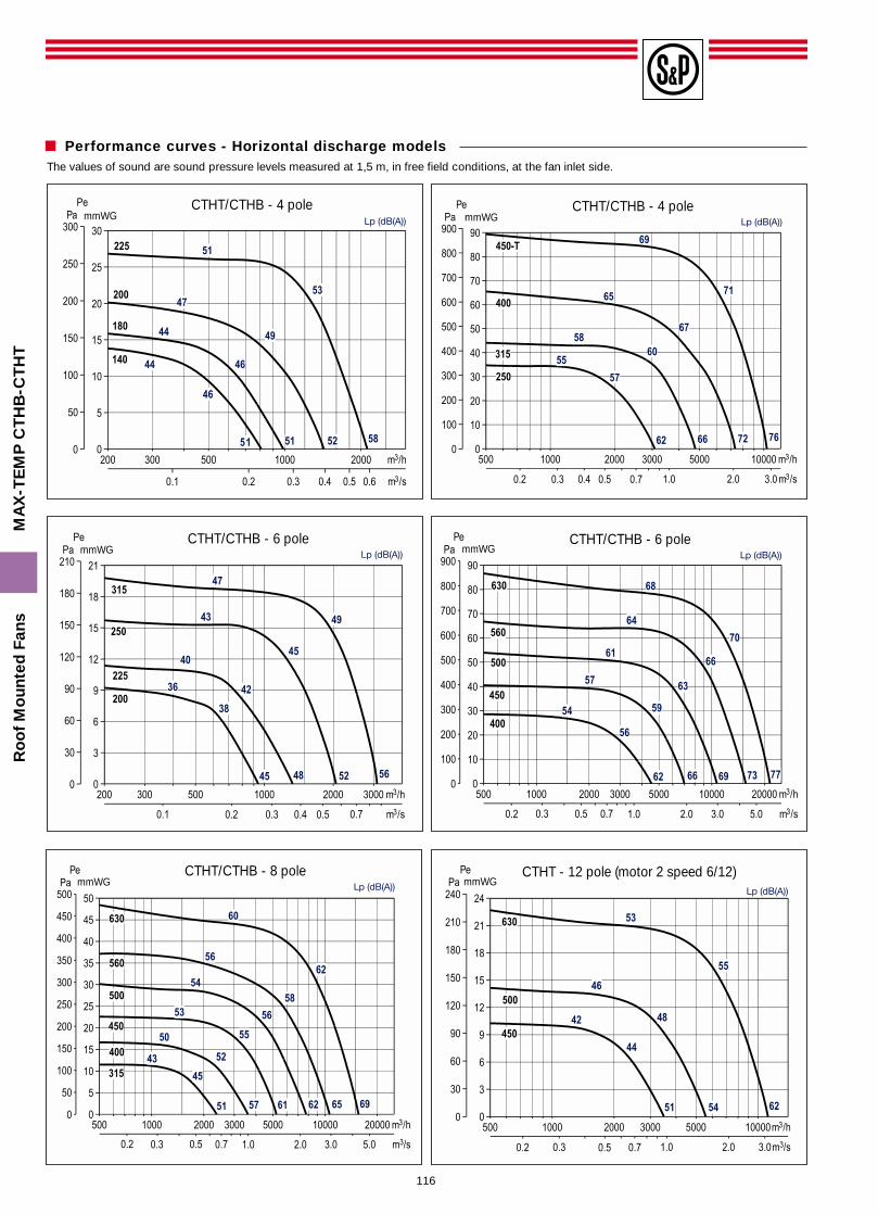
Performance curves - Horizontal discharge modelsThe values of sound are sound pressure levels measured at 1,5 m, in free field conditions, at the fan inlet side.
mmWGCTHT/CTHB - 4 pole
mmWGCTHT/CTHB - 4 pole
mmWGCTHT/CTHB - 6 pole
mmWGCTHT/CTHB - 6 pole
mmWGCTHT/CTHB - 8 pole
mmWGCTHT - 12 pole (motor 2 speed 6/12)
117
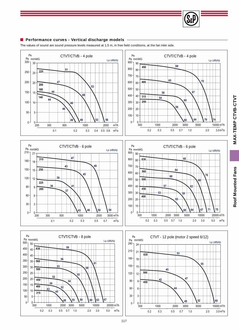
Performance curves - Vertical discharge models
Ro
of
Mo
unte
d F
ans
MA
X-T
EM
P C
TV
B-C
TV
T
The values of sound are sound pressure levels measured at 1,5 m, in free field conditions, at the fan inlet side.
mmWGCTVT/CTVB - 4 pole
mmWGCTVT/CTVB - 4 pole
mmWGCTVT/CTVB - 6 pole
mmWGCTVT/CTVB - 6 pole
mmWGCTVT/CTVB - 8 pole
mmWGCTVT - 12 pole (motor 2 speed 6/12)
118
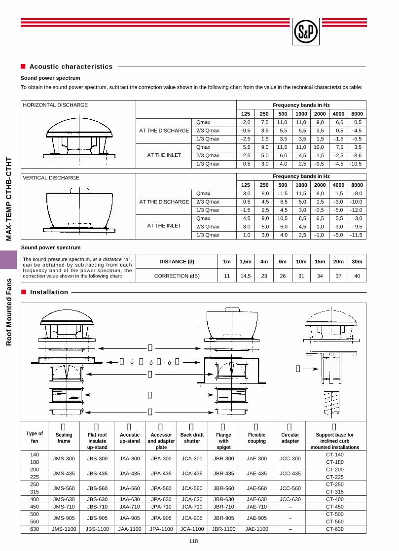
Sound power spectrum
To obtain the sound power spectrum, subtract the correction value shown in the following chart from the value in the technical characteristics table:
HORIZONTAL DISCHARGE Frequency bands in Hz
125 250 500 1000 2000 4000 8000
Qmax 2,0 7,5 11,0 11,0 9,0 6,0 0,5
2/3 Qmax -0,5 3,5 5,5 5,5 3,5 0,5 -4,5
1/3 Qmax -2,5 1,5 3,5 3,5 1,5 -1,5 -6,5
Qmax 5,5 9,0 11,5 11,0 10,0 7,5 3,5
2/3 Qmax 2,5 5,0 6,0 4,5 1,5 -2,5 -8,6
1/3 Qmax 0,5 3,0 4,0 2,5 -0,5 -4,5 -10,5
VERTICAL DISCHARGE Frequency bands in Hz
125 250 500 1000 2000 4000 8000
Qmax 3,0 8,0 11,5 11,5 8,0 1,5 -8,0
2/3 Qmax 0,5 4,5 6,5 5,0 1,5 -3,0 -10,0
1/3 Qmax -1,5 2,5 4,5 3,0 -0,5 -5,0 -12,0
Qmax 4,5 9,0 10,5 8,5 6,5 5,5 3,0
2/3 Qmax 3,0 5,0 6,0 4,5 1,0 -3,0 -9,5
1/3 Qmax 1,0 3,0 4,0 2,5 -1,0 -5,0 -11,5
The sound pressure spectrum, at a distance “d”,can be obtained by subtracting from eachfrequency band of the power spectrum, thecorrection value shown in the following chart:
DISTANCE (d) 1m 1,5m 4m 6m 10m 15m 20m 30m
CORRECTION (dB) 11 14,5 23 26 31 34 37 40
Ro
of
Mo
unte
d F
ans
MA
X-T
EM
P C
TH
B-C
TH
T
Sound power spectrum
Acoustic characteristics
AT THE DISCHARGE
AT THE INLET
AT THE DISCHARGE
AT THE INLET
Installation
➀ ➁ ➂ ➃ ➄ ➅ ➆ ➇ ➈Type of Sealing Flat roof Acoustic Accessor Back draft Flange Flexible Circular Support base for
fan frame insulate up-stand and adapter shutter with couping adapter inclined curbup-stand plate spigot mounted installations
140JMS-300 JBS-300 JAA-300 JPA-300 JCA-300 JBR-300 JAE-300 JCC-300
CT-140180 CT-180200
JMS-435 JBS-435 JAA-435 JPA-435 JCA-435 JBR-435 JAE-435 JCC-435CT-200
225 CT-225250
JMS-560 JBS-560 JAA-560 JPA-560 JCA-560 JBR-560 JAE-560 JCC-560CT-250
315 CT-315400 JMS-630 JBS-630 JAA-630 JPA-630 JCA-630 JBR-630 JAE-630 JCC-630 CT-400450 JMS-710 JBS-710 JAA-710 JPA-710 JCA-710 JBR-710 JAE-710 – CT-450500
JMS-905 JBS-905 JAA-905 JPA-905 JCA-905 JBR-905 JAE-905 –CT-500
560 CT-560630 JMS-1100 JBS-1100 JAA-1100 JPA-1100 JCA-1100 JBR-1100 JAE-1100 – CT-630
➀
➃
➄
➆
➅
ó ó➁ ➂ ó ➈➇
119
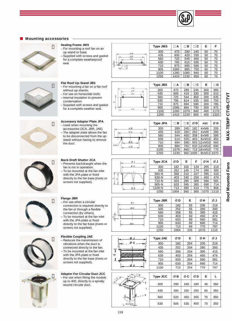
Type JMS � A � B � C E F
300 470 290 245 50 70435 600 420 330 50 70560 725 545 450 50 70630 795 615 535 50 70710 875 695 590 50 70905 1065 885 750 60 70
1100 1260 1080 840 60 701250 1410 1230 950 60 70
Type JBS � A � B � C E � G
300 470 289 245 300 380435 600 419 330 300 510560 725 544 450 300 635630 795 614 535 300 705710 875 694 590 300 785905 1065 884 750 300 9751100 1260 1079 840 400 11701250 1410 1230 950 400 1320
Type JPA � B � C Ø D nxt Ø H
300 289 245 182 4xM6 205435 419 330 252 4xM8 280560 544 450 358 8xM8 395630 614 535 403 8xM10 450710 694 590 503 12xM10 560905 884 750 633 12xM10 690
1100 1079 840 713 16xM10 7701250 1230 950 1000 8xM12 1070
Type JCA Ø D E F Ø H Ø J
300 182 100 124 205 219435 252 145 174 280 300
560-N 358 210 227 395 415630-N 403 240 250 450 474710-N 503 285 300 560 581905-N 633 345 365 690 714
1100-N 713 390 410 770 8061250 1004 560 560 1070 1110
Type JBR Ø D E Ø H Ø J
300 182 55 205 219435 252 55 280 300560 358 55 395 415630 403 63 450 474710 503 69 560 581905 633 69 690 714
1100 713 69 770 7971250 1004 105 1070 1110
Type JAE Ø D E Ø H Ø J
300 182 254 205 219435 252 254 280 300560 358 254 395 415630 403 254 450 474710 503 254 560 581905 633 254 690 714
1100 713 254 770 797
A
B
C
E
F
A
B
C
300
G
B
C
Ø D
Hn x t
Ø J
E
Ø H
Ø D
F
Type JCC Ø B Ø C Ø D E L
300 290 245 180 45 350
435 390 330 250 60 350
560 520 450 355 70 350
630 605 535 400 70 350
Ø J
Ø H
Ø D
E
Ø D NOM.
EB
L
C
Sealing Frame JMS– For mounting a roof fan on an
up-stand or base.– Supplied with screws and gasket
for a complete weatherproofseal.
Flat Roof Up-Stand JBS– For mounting a fan on a flat roof
without up-stands.– For use on horizontal roofs.– Internal insulation to prevent
condensation.– Supplied with screws and gasket
for a complete weather seal.
Accessory Adapter Plate JPA – Used when mounting the
accessories (JCA, JBR, JAE).– The adapter plate allows the fan
to be disconnected from the up-stand without having to removethe duct.
Back-Draft Shutter JCA– Prevents backdraught when the
fan is not in operation.– To be mounted at the fan inlet
with the JPA plate or fixeddirectly to the fan base (rivets orscrews not supplied).
Flange JBR– For use when a circular
connection is required directly tothe fan or through a flexibleconnection (by others).
– To be mounted at the fan inletwith the JPA plate or fixeddirectly to the fan base (rivets orscrews not supplied).
Flexible Coupling JAE– Reduces the transmission of
vibrations when the duct isconnected directly to the fan.
– To be mounted at the fan inletwith the JPA plate or fixeddirectly to the fan base (rivets orscrews not supplied).
Adapter For Circular Duct JCC – For use when fitting the models
up to 400, directly to a spirallywound circular duct.
Ro
of
Mo
unte
d F
ans
MA
X-T
EM
P C
TV
B-C
TV
T
E
Mounting accessories
➀
➃
➄
➆
➅
➁
➇

120
Ro
of
Mo
unte
d F
ans
MA
X-T
EM
P C
TH
B-C
TH
T
Type JAA � A � B � C Ø D (M) H � G
300 470 290 245 13 (MI0) 750 380
435 600 419 330 15 (MI2) 750 510
560 725 545 450 15 (MI2) 750 635
630 795 615 535 15 (MI2) 750 705
710 875 695 590 18 (MI4) 1000 785
905 1065 885 750 18 (MI4) 1000 975
1100 1260 1080 840 18 (MI4) 1000 1170
Type 125 250 500 1000 2000 4000 8000
JAA-300 1 5 13 22 23 16 12
JAA-435 1 7 16 23 25 18 13
JAA-560 2 8 16 29 32 26 17
JAA-630 2 8 14 24 27 19 13
JAA-710 2 8 14 24 28 16 11
JAA-905 2 7 14 26 30 19 12
JAA-1100 2 7 16 27 32 20 13
Acoustic Up-Stand JAA– Reduces in duct and radiated
noise. – For use when mounting a fan
on a flat roof without up-stands– Supplied with screws and
gasket for a complete weatherseal.
Attenuation insertion loss dB at octave average frequencies
Attenuator pressure drops
500 1000 1500 2000 3000 4000 5000 10000 15000 20000 m3/h
15
10
5
mmCE
1100905710630560435300
STANDARD MOUNTING
REVERSE MOUNTING
STANDARD MOUNTINGWITH ACCESSORIES
REVERSE MOUNTINGWITH ACCESSORIES
mmWG
➂
B B
C
50
d
A
AVISTO POR
a
CT and HCT support base for inclined curb mountedinstallations – To ensure the correction installation of the HT product it is
essential to specify the roof pitch angle and the distancebetween the roof beam profiles (as shown).
➈ B C B C
Base CT-140 289 245 Base HCT-315 544 450
Base CT-180 289 245 Base HCT-355 614 535
Base CT-200 419 330 Base HCT-400 614 535
Base CT-225 419 330 Base HCT-450 694 590
Base CT-250 544 450 Base HCT-500 694 590
Base CT-315 544 450 Base HCT-560 884 750
Base CT-400 614 535 Base HCT-630 884 750
Base CT-450 694 590 Base HCT-710 1079 840
Base CT-500 884 750 Base HCT-800 1079 840
Base CT-560 884 750 Base HCT-900 1230 950
Base CT-630 1079 840 Base HCT-1000 1230 950Viewed in A
direction
d: Distance between the roof beam profiles a: Roof pitch angle (curb)
121
Ro
of
Mo
unte
d F
ans
MA
X-T
EM
P C
TV
B-C
TV
T
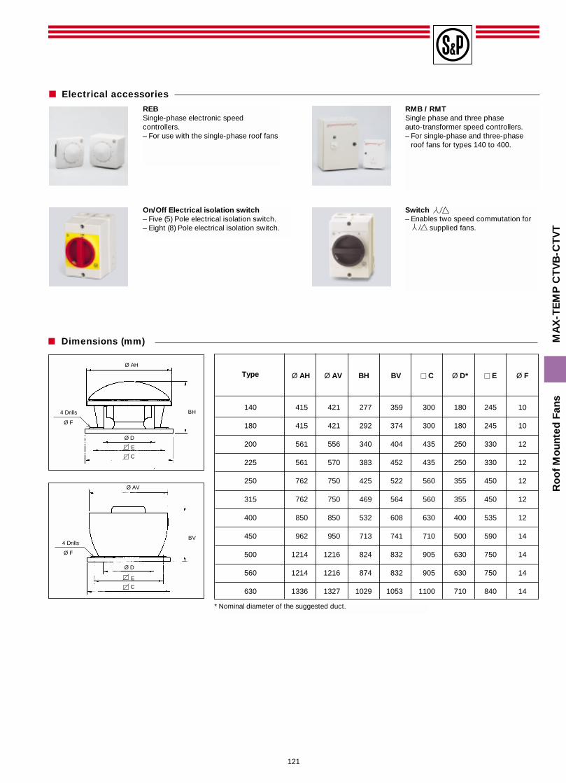
� Dimensions (mm)
REBSingle-phase electronic speedcontrollers.– For use with the single-phase roof fans
RMB / RMTSingle phase and three phaseauto-transformer speed controllers.– For single-phase and three-phase
roof fans for types 140 to 400.
Switch– Enables two speed commutation for
supplied fans.
On/Off Electrical isolation switch– Five (5) Pole electrical isolation switch.– Eight (8) Pole electrical isolation switch.
Ø AH
Ø F
4 Drills BH
E
C
Ø D
Ø AV
Ø F
4 DrillsBV
E
C
Ø D
Type Ø AH Ø AV BH BV � C Ø D* � E Ø F
140 415 421 277 359 300 180 245 10
180 415 421 292 374 300 180 245 10
200 561 556 340 404 435 250 330 12
225 561 570 383 452 435 250 330 12
250 762 750 425 522 560 355 450 12
315 762 750 469 564 560 355 450 12
400 850 850 532 608 630 400 535 12
450 962 950 713 741 710 500 590 14
500 1214 1216 824 832 905 630 750 14
560 1214 1216 874 832 905 630 750 14
630 1336 1327 1029 1053 1100 710 840 14
* Nominal diameter of the suggested duct.
Electrical accessories