Embed Size (px)
Citation preview
Satellite TV AntennasRoof-Mounted Dome Antennas 46
Roof-Mounted Dome Antennas
For up-to-date information on receiver compatibility & programming,
visit www.winegard.com/receivers
Roof-Mounted Dome Antennas | Installation
Satellite TV AntennasRoof-Mounted Dome Antennas47
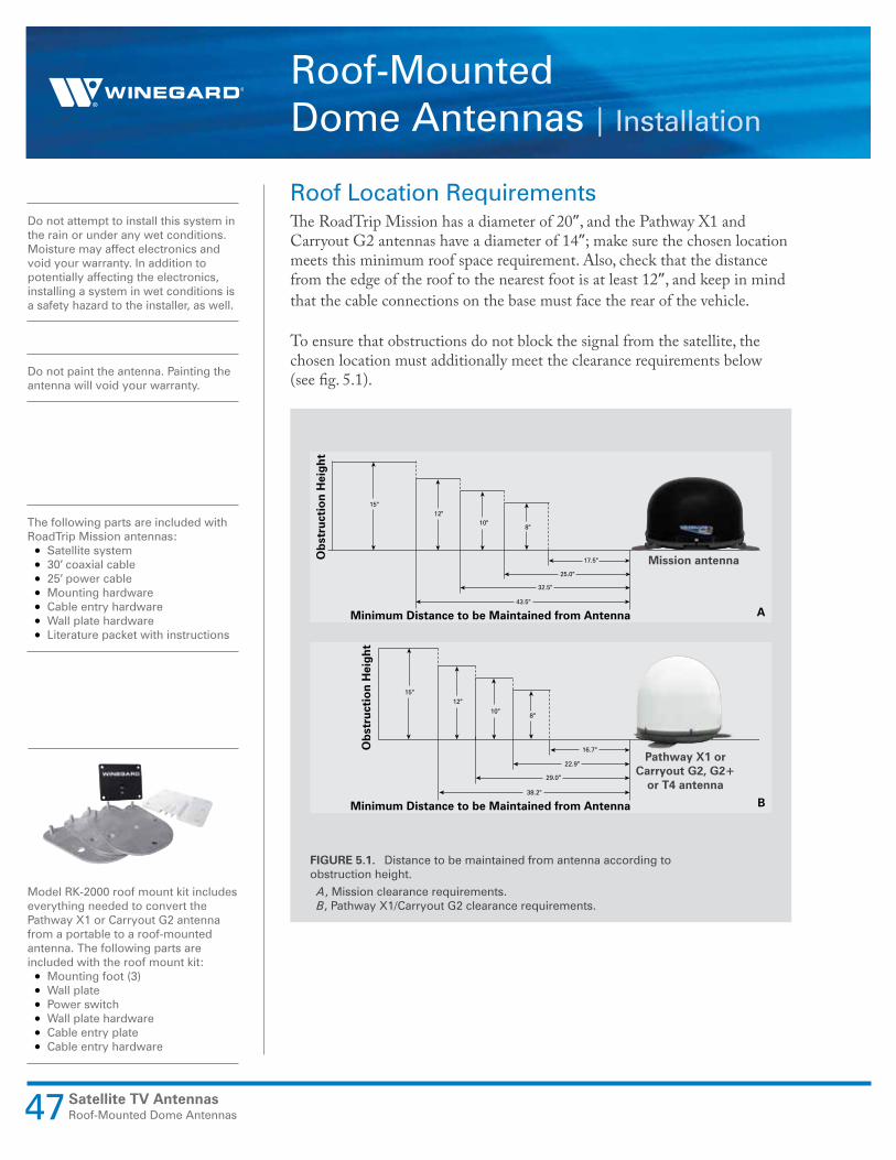
Roof Location RequirementsThe RoadTrip Mission has a diameter of 20”, and the Pathway X1 and Carryout G2 antennas have a diameter of 14”; make sure the chosen location meets this minimum roof space requirement. Also, check that the distance from the edge of the roof to the nearest foot is at least 12”, and keep in mind that the cable connections on the base must face the rear of the vehicle.
To ensure that obstructions do not block the signal from the satellite, the chosen location must additionally meet the clearance requirements below (see fig. 5.1).
8"10"
17.5"
12"15"
25.0"
32.5"
43.5"
Ob
stru
ctio
n H
eigh
t
Minimum Distance to be Maintained from Antenna
Mission antenna
A
8"10"
16.7"
12"15"
22.9"
29.0"
38.2"
Ob
stru
ctio
n H
eigh
t
Minimum Distance to be Maintained from Antenna
Pathway X1 or Carryout G2, G2+
or T4 antenna
B
FIGURE 5.1. Distance to be maintained from antenna according to obstruction height.
A, Mission clearance requirements.B, Pathway X1/Carryout G2 clearance requirements.
The following parts are included with RoadTrip Mission antennas:• Satellite system• 30′ coaxial cable• 25′ power cable• Mounting hardware• Cable entry hardware• Wall plate hardware• Literature packet with instructions
Do not attempt to install this system in the rain or under any wet conditions. Moisture may affect electronics and void your warranty. In addition to potentially affecting the electronics, installing a system in wet conditions is a safety hazard to the installer, as well.
Do not paint the antenna. Painting the antenna will void your warranty.
Model RK-2000 roof mount kit includes everything needed to convert the Pathway X1 or Carryout G2 antenna from a portable to a roof-mounted antenna. The following parts are included with the roof mount kit:• Mounting foot (3)• Wall plate• Power switch• Wall plate hardware• Cable entry plate• Cable entry hardware

Roof-Mounted Dome Antennas | Installation
Satellite TV AntennasRoof-Mounted Dome Antennas 48
For best performance and to reduce signal acquisition time, park the vehicle on a level surface that is free of obstructions such as trees or buildings.
Switch SettingsThe RoadTrip T4, Carryout G2 and G2+ antennas are preset for DIRECTV programming. If using these antennas with DISH or Bell TV™ programming, change the numbered dip switches found on the electronics box.
TABLE 5.1. Switch settings for RoadTrip T4, Carryout G2 and G2+ antennas according to provider
Primary Satellite Alternate Satellite Switch settings
DIRECTV 101° 119°
1 2 3 4 5 6 7 8
DISH 119° 110°/129°
1 2 3 4 5 6 7 8
Bell TV 91° 82°
1 2 3 4 5 6 7 8
To complete a successful search, the antenna must locate the primary satellite but does not need to locate alternate satellites. If the dome was removed to change the switch settings, place the dome back over the base, and insert and tighten the dome screws.
Installing the Antenna on the RoofBefore installing the Pathway X1, Carryout G2 or G2+ antenna, the rubber feet must be removed, and the metal feet must be installed (refer to pg. 4). Then, choose a location to install the roof-mounted satellite TV antenna, and place the antenna in the chosen location. Do not place the antenna upside-down on the roof as this may cause damage to the dome. Rotate the base until the cable connections face the back of the vehicle. Level the base front-to-back and side-to-side. Once the antenna is in the chosen location, trace around each foot. Remove the antenna from the installation area, and apply sealant in the traced area. Carefully place the feet directly onto the sealant. Check with your vehicle manufacturer for any special screw requirements for your vehicle, and screw each foot to the roof.
Switch is up Switch is down
Key for Table 2.5
If the base is not level, the antenna may require more time to locate the correct satellite or may not locate the correct satellite.
The antenna should not be connected to 12 VDC power when changing dip switch settings.
Satellite TV AntennasRoof-Mounted Dome Antennas49
Roof-Mounted Dome Antennas | Installation
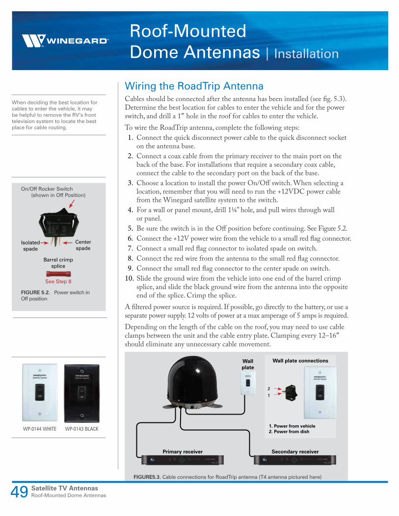
Wiring the RoadTrip AntennaCables should be connected after the antenna has been installed (see fig. 5.3). Determine the best location for cables to enter the vehicle and for the power switch, and drill a 1” hole in the roof for cables to enter the vehicle.To wire the RoadTrip antenna, complete the following steps:1. Connect the quick disconnect power cable to the quick disconnect socket
on the antenna base. 2. Connect a coax cable from the primary receiver to the main port on the
back of the base. For installations that require a secondary coax cable, connect the cable to the secondary port on the back of the base.
3. Choose a location to install the power On/Off switch. When selecting a location, remember that you will need to run the +12VDC power cable from the Winegard satellite system to the switch.
4. For a wall or panel mount, drill 1¼” hole, and pull wires through wall or panel.
5. Be sure the switch is in the Off position before continuing. See Figure 5.2.6. Connect the +12V power wire from the vehicle to a small red flag connector.7. Connect a small red flag connector to isolated spade on switch.8. Connect the red wire from the antenna to the small red flag connector.9. Connect the small red flag connector to the center spade on switch.
10. Slide the ground wire from the vehicle into one end of the barrel crimp splice, and slide the black ground wire from the antenna into the opposite end of the splice. Crimp the splice.
A filtered power source is required. If possible, go directly to the battery, or use a separate power supply. 12 volts of power at a max amperage of 5 amps is required.Depending on the length of the cable on the roof, you may need to use cable clamps between the unit and the cable entry plate. Clamping every 12–16” should eliminate any unnecessary cable movement.
Primary receiver Secondary receiver
Wall plate
Wall plate connections
1. Power from vehicle2. Power from dish
2
1
FIGURE5.3. Cable connections for RoadTrip antenna (T4 antenna pictured here)
When deciding the best location for cables to enter the vehicle, it may be helpful to remove the RV’s front television system to locate the best place for cable routing.
On/Off Rocker Switch (shown in Off Position)
Isolated spade
Center spade
FIGURE 5.2. Power switch in Off position
WP-0144 WHITE WP-0143 BLACK
Barrel crimp splice
See Step 8

Satellite TV AntennasRoof-Mounted Dome Antennas 50
Roof-Mounted Dome Antennas | Installation
Wiring the Pathway X1 or Carryout G2 AntennaBefore wiring the Pathway X1 or Carryout G2 antenna, the roof-mount feet must be installed on the antenna. To install the mounting feet, complete the following steps:1. If the handle has been installed, remove the screws holding the handle to
the antenna with a Phillips screwdriver, and remove the handle.2. Using a Phillips screwdriver, remove the feet from the bottom of the base.3. Remove the dome screws with a Phillips screwdriver. Remove the dome. 4. Remove the two nuts holding the eyelet to the base with a 3/8” socket
wrench. Remove the eyelet. 5. Insert the two threaded posts on a mounting foot through the two holes
from which the eyelet was removed, and thread a hex nut onto each post.6. Locate the other holes for the remaining two mounting feet, keeping in
mind that the feet should be equally spaced around the base. Install the remaining two mounting feet.
7. Using a 3/8” socket wrench, tighten all hex nuts holding the mounting feet to the base.
8. Place the dome back onto the base, and re-install dome screws.
To wire the Pathway X1 or Carryout G2 antenna, complete the following steps:1. Connect a coax cable from the primary receiver to the main port on the
back of the base. For installations that require a secondary coax cable, connect the cable to the secondary port on the back of the base.
2. If there is a power socket on the base, connect one end of the power cable to the power socket on the base. If the antenna requires connection to a 12V power source via a power cable, cut off the power cord 12V plug.
3. Drill a hole in the roof for the cables, and push the wires inside. Install the provided cable entry plate over the hole and cables.
To install the power switch (not used with the Pathway X1 antenna), complete the following steps:1. Choose a location to install the power On/Off switch. When selecting a
location, remember that you will need to run the +12VDC power cable from the Winegard satellite system to the switch.
2. For a wall or panel mount, drill 1¼” hole, and pull wires through wall or panel.
3. Be sure the switch is in the Off position before continuing. See Figure 5.2.4. Connect the +12V power wire from the vehicle to a small red flag connector.5. Connect a small red flag connector to isolated spade on switch.6. Connect the red wire from the antenna to the small red flag connector.7. Connect the small red flag connector to the center spade on switch.8. Slide the ground wire from the vehicle into one end of the barrel crimp
splice, and slide the black ground wire from the antenna into the opposite end of the splice. Crimp the splice.
The power switch and power cable will not be used with the Pathway X1 antenna. The Pathway X1 antenna is powered through the receiver.
The wall plate and power switch provided with the roof mount kit are different from the wall plate and power switch provided with the RoadTrip antennas (see fig. 5.4).
Wall plate
Power switch
FIGURE 5.4. Wall plate and power switch included with roof mount kit

Satellite TV AntennasRoof-Mounted Dome Antennas51
Roof-Mounted Dome Antennas | Installation
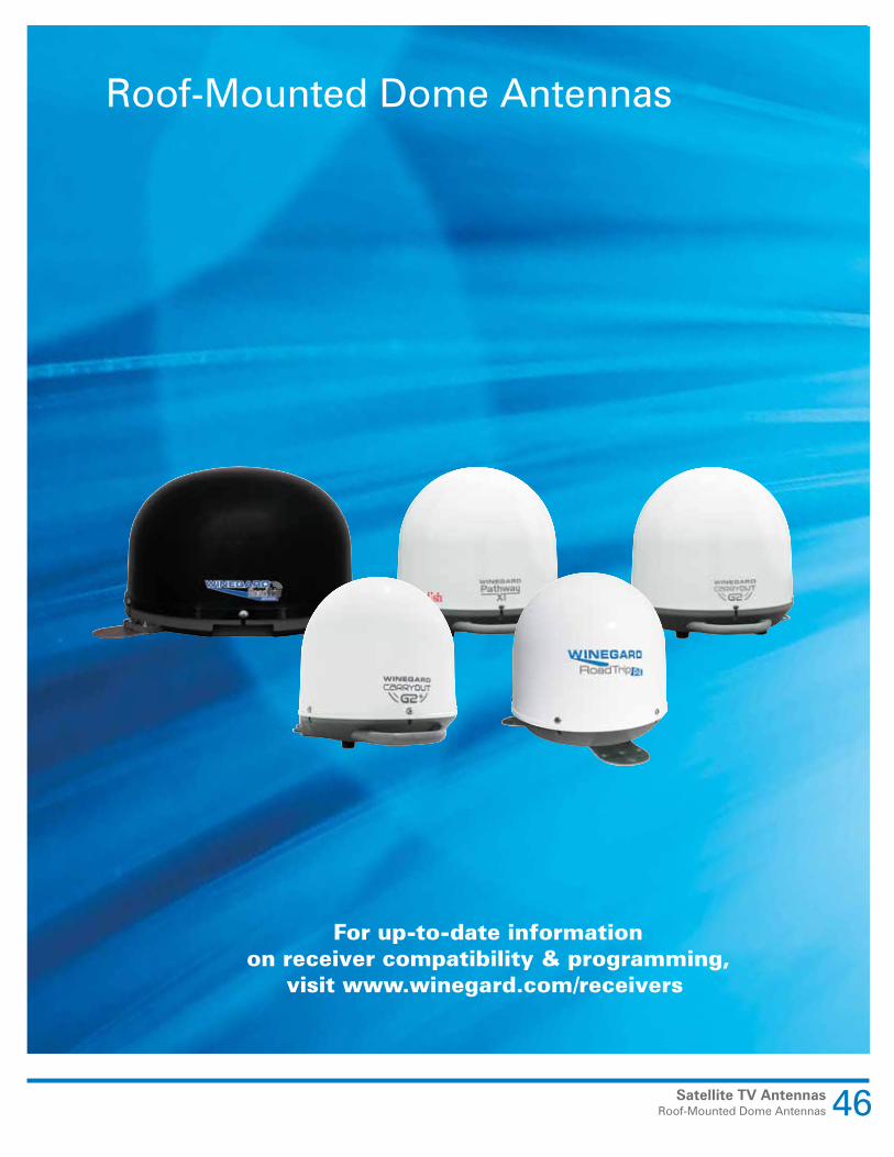
Wiring the Carryout G2+ AntennaWith the power button on the power inserter in the OFF position (not pressed in), connect the primary port of the Carryout G2+ to the ANTENNA port on the power inserter with the 25’ coaxial cable. With your fingers, twist the cable on, and tighten a quarter turn more with a wrench. Do not overtighten.
Connect the “SAT IN” port of your satellite receiver to the RECEIVER port of the power inserter with the 3' coaxial cable. With your fingers, twist the cable on, and tighten a quarter turn more with a wrench. Do not overtighten.
Power Inserter
Receiver
Coax to Antenna
Power Adapter
FIGURE 5.6. Carryout G2+ receiver setup
FIGURE 5.5. Wiring the Carryout G2+ antenna

Satellite TV AntennasRoof-Mounted Dome Antennas 52
Roof-Mounted Dome Antennas | Installation
The DISH Wally or 211z receiver and DIRECTV H24 single tuner receiver are recommended for use with RoadTrip or Carryout G2 antennas (see fig. 5.9). The Pathway X1 is exclusively compatible with DISH Solo HD receivers such as the Wally and 211z receiver.
FIGURE 5.9. Receivers. A, DISH Wally B, DIRECTV H24
A
SealingApply sealant around the edge of feet and over screws (see fig. 5.7). When sealing the RoadTrip antenna, do not apply sealant to the hex nuts on the feet. This way, the antenna can be removed (if necessary) from the roof without breaking the sealant (see fig. 5.8).
After wiring the antenna, seal around the hole where cables enter the vehicle and in-between cables. Fasten the cable entry plate to the roof, and seal around the perimeter of the cable entry plate, especially the point at which cables enter the plate (see fig. 5.8). Allow sealant adequate time to cure.
Receiver RecommendationsWinegard RoadTrip, Carryout G2 and G2+ antennas will operate with most DISH and DIRECTV receivers. Winegard recommends using a single tuner receiver. Recommended models include the DISH Wally, 211z and DIRECTV H24 receivers. Winegard does not recommend using receivers with built-in hard drives not recommended by the manufacturer for mobile applications. These receivers are more susceptible to issues due to excessive heat and/or vibrations found in RV installations. See NOTE at right.The Pathway X1 antenna is exclusively compatible with DISH Solo HD receivers Wally and 211z.
FIGURE 5.7. Sealant applied over RoadTrip antenna foot and screws.
FIGURE 5.8. Sealant applied over cable entry plate and around cable entry hole.
NOTE: The DIRECTV HD programming will not be available with RoadTrip or Carryout G2 antennas even if a DIRECTV HD receiver is used.

Satellite TV AntennasRoof-Mounted Dome Antennas53
Roof-Mounted Dome Antennas | Installation
DISH Receiver Setup—RoadTrip G2 & G2+ Before turning on the antenna, complete the following steps to clear out existing receiver settings in order to set up the RoadTrip, Carryout G2 or G2+ antenna for use with DISH programming (see fig. 5.10 and 5.11). Before starting, disconnect the coax cable from the “Sat In” port on the back of the receiver. If your receiver differs from the options shown, you may need to consult your receiver manual. The wording and display used in your receiver may differ slightly.
Online receiver setup guides are available for Winegard antennas at www.winegard.com/receivers/setupguide.php.
Receiver setup must be completed for each receiver being used with the roof-mounted satellite TV antenna. When setting up a secondary receiver for use with the antenna, connect the secondary receiver to the main port. After receiver setup is complete, re-connect the secondary receiver to the secondary port and the primary receiver to the main port.
Mike’s Note: If 1 DISH receiver will not let you into the menus, try pressing *#*# on the remote (this works about 30% of the time) OR hold the power button in continuously untill the picture goes blank. When the picture comes back on, you need to press the menu within 3 seconds.
Step 1Before starting, make sure the coax cable is disconnected from the “Sat In” port on the back of the receiver. Press Menu on your remote. Select option 6, “System Setup.”
Step 2Select option 1, “Installation.”
Step 3Select option 1, “Point Dish.”
FIGURE 5.10. Steps 1–3 of DISH receiver setup for RoadTrip, Carryout G2 & G2+ antennas
Satellite TV AntennasRoof-Mounted Dome Antennas 54
Roof-Mounted Dome Antennas | Installation
A tracking antenna will be completely silent when in Standby mode unless the dish toggles to a different satellite when a channel is requested by the remote control.
The SW64 switch is a DISH receiver setting (not a physical part).
If the SW64 switch is not installed after completing Step 6 with an older model of receiver, try checking “SuperDISH” or “Alternate” before selecting “Test.” Switch SW42 was used on domes before HD came out.
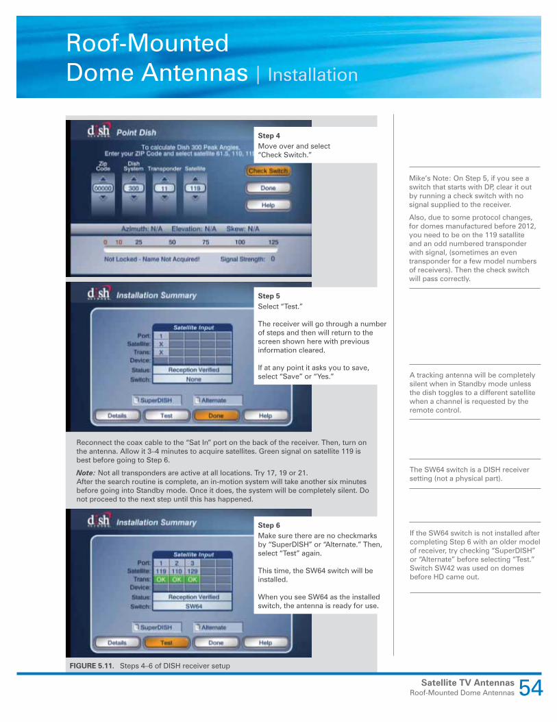
Mike’s Note: On Step 5, if you see a switch that starts with DP, clear it out by running a check switch with no signal supplied to the receiver.
Also, due to some protocol changes, for domes manufactured before 2012, you need to be on the 119 satallite and an odd numbered transponder with signal, (sometimes an even transponder for a few model numbers of receivers). Then the check switch will pass correctly.
Step 4Move over and select “Check Switch.”
Step 5Select “Test.”
The receiver will go through a number of steps and then will return to the screen shown here with previous information cleared.
If at any point it asks you to save, select “Save” or “Yes.”
Step 6Make sure there are no checkmarks by “SuperDISH” or “Alternate.” Then, select “Test” again.
This time, the SW64 switch will be installed.
When you see SW64 as the installed switch, the antenna is ready for use.
Reconnect the coax cable to the “Sat In” port on the back of the receiver. Then, turn on the antenna. Allow it 3–4 minutes to acquire satellites. Green signal on satellite 119 is best before going to Step 6.
Note: Not all transponders are active at all locations. Try 17, 19 or 21.After the search routine is complete, an in-motion system will take another six minutes before going into Standby mode. Once it does, the system will be completely silent. Do not proceed to the next step until this has happened.
FIGURE 5.11. Steps 4–6 of DISH receiver setup
Satellite TV AntennasRoof-Mounted Dome Antennas55
Roof-Mounted Dome Antennas | Installation
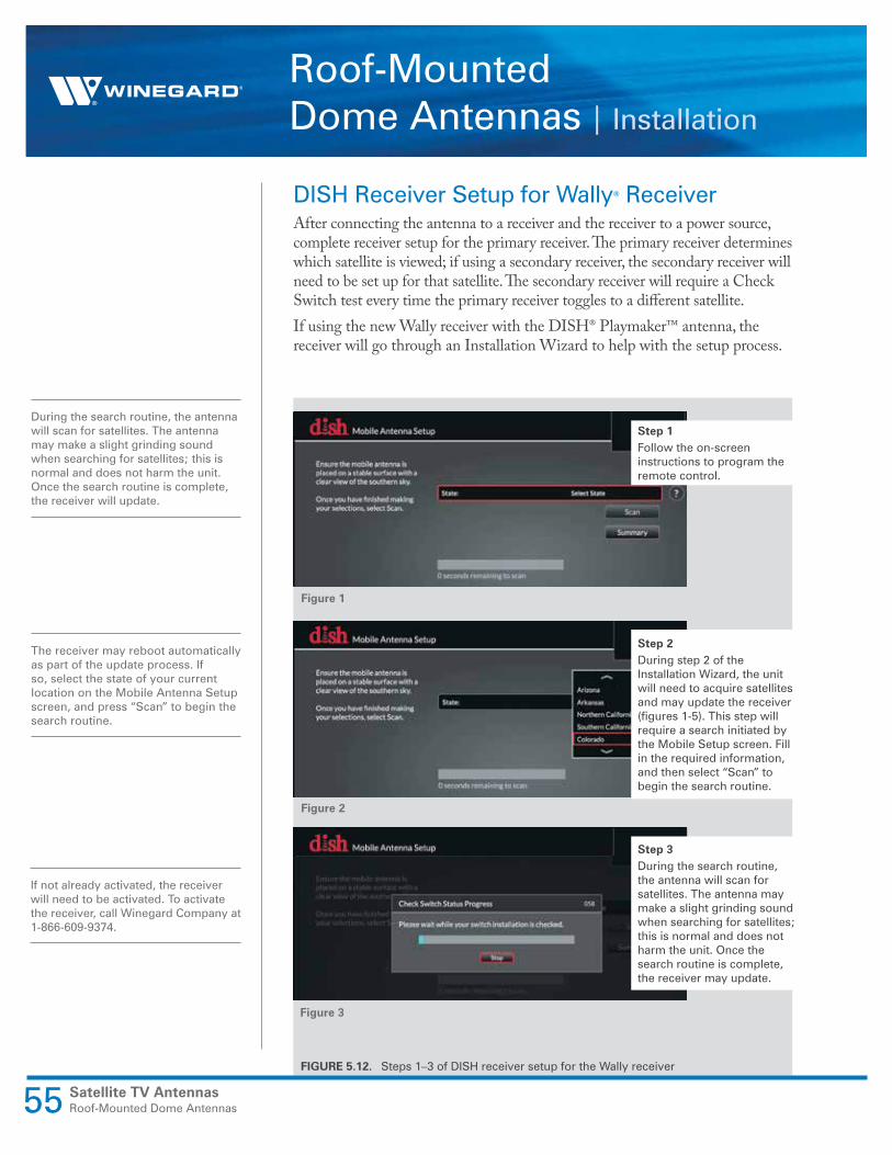
DISH Receiver Setup for Wally® ReceiverAfter connecting the antenna to a receiver and the receiver to a power source, complete receiver setup for the primary receiver. The primary receiver determines which satellite is viewed; if using a secondary receiver, the secondary receiver will need to be set up for that satellite. The secondary receiver will require a Check Switch test every time the primary receiver toggles to a different satellite.If using the new Wally receiver with the DISH® Playmaker™ antenna, the receiver will go through an Installation Wizard to help with the setup process.
During the search routine, the antenna will scan for satellites. The antenna may make a slight grinding sound when searching for satellites; this is normal and does not harm the unit. Once the search routine is complete, the receiver will update.
If not already activated, the receiver will need to be activated. To activate the receiver, call Winegard Company at 1-866-609-9374.
The receiver may reboot automatically as part of the update process. If so, select the state of your current location on the Mobile Antenna Setup screen, and press “Scan” to begin the search routine.
Figure 1
Figure 2
Figure 3
Step 1Follow the on-screen instructions to program the remote control.
Step 2During step 2 of the Installation Wizard, the unit will need to acquire satellites and may update the receiver (figures 1-5). This step will require a search initiated by the Mobile Setup screen. Fill in the required information, and then select “Scan” to begin the search routine.
Step 3During the search routine, the antenna will scan for satellites. The antenna may make a slight grinding sound when searching for satellites; this is normal and does not harm the unit. Once the search routine is complete, the receiver may update.
FIGURE 5.12. Steps 1–3 of DISH receiver setup for the Wally receiver

Satellite TV AntennasRoof-Mounted Dome Antennas 56
Roof-Mounted Dome Antennas | Installation
FIGURE 5.13. Steps 4–8 of DISH receiver setup for the Wally receiver
IF the steps in the Troubleshooting section (page 64) do not resolve the error, re-boot the receiver and start the Mobile Antenna Setup again; often, this will resolve the problem. If the problem persists, contact Winegard Technical Services at [email protected] or 1-800-788-4417.
Figure 5
Figure 6
Figure 7
Figure 8
Figure 4
Step 4 The receiver may reboot automatically as part of the update process. If so, select the state of your current location on the Mobile Antenna Setup screen as in figure 2. Press “Scan” to begin the search routine.The satellite will search for and acquire satellites.
Step 5If not already activated, the receiver will need to be activated (figure 6). To activate the receiver, call Winegard Company at 1-866-593-0348.
Step 6After the receiver has been activated, the receiver will begin acquiring signal (figure 7) and downloading the Electronic Programming Guide (figure 8). Once the download is complete, you can start watching TV.

DIRECTV Receiver Setup—RoadTrip, G2 & G2+ AntennasComplete the following steps to set up the RoadTrip, Carryout G2 or G2+ antenna for use with DIRECTV programming (see fig. 5.14, & 5.15).
If your receiver differs from the options shown, you may need to consult your receiver manual. The wording and display used in your receiver may differ slightly.
Online receiver setup guides are available for Winegard antennas at www.winegard.com/receivers/setupguide.php.
Images shown are from a H24 receiver. HD receiver screens and steps may vary slightly.
Mike’s Note: From the Searching screen, if you cannot get into the menus, you could wait 10 minutes for the receiver to timeout or just continuously hold down the info button on the remote until a menu pops up.
Satellite TV AntennasRoof-Mounted Dome Antennas57
Roof-Mounted Dome Antennas | Installation
Step 1Press the Menu button on your remote. Select “Settings.”
Step 2Select “Satellite.”
Step 3Identify the Satellite menu in the receiver menu. Once there, find the option for satellite setup.
FIGURE 5.14. Steps 1–3 of DIRECTV receiver setup

Satellite TV AntennasRoof-Mounted Dome Antennas 58
Roof-Mounted Dome Antennas | Installation
A tracking antenna will be completely silent when in Standby mode.
If you would like to check signal strengths, choose “Signal Strength” from the menu options before returning to this screen.
After completing receiver setup for DISH or DIRECTV, the process will only need repeated if changed by the user. If the user is using the receiver at home, different settings will be required for home use.
Mike’s Note: On step 6, if the counter to 100% stalls out, the wrong dish type is selected. See the recommended setting in the manual for the antenna you are using.
Step 4Select “3-LNB (18″x20″)” or “3 Satellites.” If given the option of SWM or Multi-switch, select “Multiswitch.”Turn on the antenna. Allow it 3–4 minutes to acquire satellites. An in-motion system will then take another six minutes before going into Standby mode. Do not proceed to the next step until this has happened.
Step 5Errors may be displayed on the Installation Status screen. It is normal to see one or two boxes with an ‘X’ instead of a ‘ .’
Select “Continue.”
Step 6Select “Continue.” The program guide will download. When the status bar reaches 100%, press “Continue.”
FIGURE 5.15. Steps 4–6 of DIRECTV receiver setup
Satellite TV AntennasRoof-Mounted Dome Antennas59
Roof-Mounted Dome Antennas | Receiver Setup
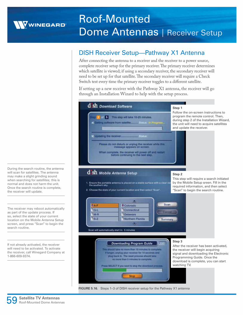
DISH Receiver Setup—Pathway X1 AntennaAfter connecting the antenna to a receiver and the receiver to a power source, complete receiver setup for the primary receiver. The primary receiver determines which satellite is viewed; if using a secondary receiver, the secondary receiver will need to be set up for that satellite. The secondary receiver will require a Check Switch test every time the primary receiver toggles to a different satellite.If setting up a new receiver with the Pathway X1 antenna, the receiver will go through an Installation Wizard to help with the setup process.
During the search routine, the antenna will scan for satellites. The antenna may make a slight grinding sound when searching for satellites; this is normal and does not harm the unit. Once the search routine is complete, the receiver will update.
If not already activated, the receiver will need to be activated. To activate the receiver, call Winegard Company at 1-866-609-9374.
The receiver may reboot automatically as part of the update process. If so, select the state of your current location on the Mobile Antenna Setup screen, and press “Scan” to begin the search routine.
Step 1Follow the on-screen instructions to program the remote control. Then, during step 2 of the Installation Wizard, the unit will need to acquire satellites and update the receiver.
Step 2This step will require a search initiated by the Mobile Setup sreen. Fill in the required information, and then select “Scan” to begin the search routine.
Step 3After the receiver has been activated, the receiver will begin acquiring signal and downloading the Electronic Programming Guide. Once the download is complete, you can start watching TV.
FIGURE 5.16. Steps 1–3 of DISH receiver setup for the Pathway X1 antenna
Satellite TV AntennasRoof-Mounted Dome Antennas 60
Roof-Mounted Dome Antennas | Receiver Setup
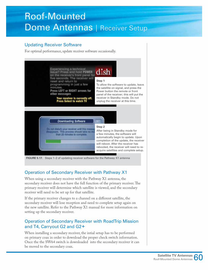
Updating Receiver SoftwareFor optimal performance, update receiver software occasionally.
Operation of Secondary Receiver with Pathway X1When using a secondary receiver with the Pathway X1 antenna, the secondary receiver does not have the full function of the primary receiver. The primary receiver will determine which satellite is viewed, and the secondary receiver will need to be set up for that satellite.If the primary receiver changes to a channel on a different satellite, the secondary receiver will lose reception and need to complete setup again on the new satellite. Refer to the Pathway X1 manual for more information on setting up the secondary receiver.
Operation of Secondary Receiver with RoadTrip Mission and T4, Carryout G2 and G2+When installing a secondary receiver, the intial setup has to be performed on primary coax in order to download the proper check switch information. Once the the SW64 switch is downloaded into the secondary receiver it can be moved to the secondary coax.
FIGURE 5.17. Steps 1–2 of updating receiver software for the Pathway X1 antenna
Step 1To allow the software to update, leave the satellite on signal, and press the Power button the remote or front panel of the receiver; this will put the receiver in Standby mode. Do not unplug the receiver at this time.
Step 2After being in Standby mode for a few minutes, the software will automatically begin to update. Upon completion of the update, the receiver will reboot. After the receiver has rebooted, the receiver will need to re-acquire satellites and complete setup.
Satellite TV AntennasRoof-Mounted Dome Antennas61
Roof-Mounted Dome Antennas | Operation
Five Basic Steps to OperationThere are five basic steps to operation; however, some steps are only used with in-motion systems. The five basic steps are homing, GPS acquisition, searching, tracking, and standby.
HomingAfter turning on the power switch, the roof-mounted satellite TV antenna will make a series of movements to check its rotational limits. As the antenna checks its rotational limits, you may hear a slight grinding sound. This process ensures that the satellite dish knows where it is pointing relative to its mechanical limits.
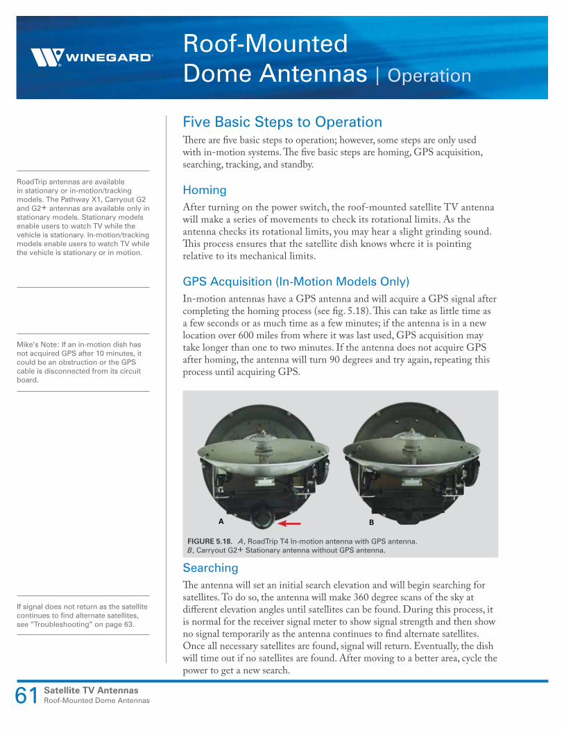
GPS Acquisition (In-Motion Models Only)In-motion antennas have a GPS antenna and will acquire a GPS signal after completing the homing process (see fig. 5.18). This can take as little time as a few seconds or as much time as a few minutes; if the antenna is in a new location over 600 miles from where it was last used, GPS acquisition may take longer than one to two minutes. If the antenna does not acquire GPS after homing, the antenna will turn 90 degrees and try again, repeating this process until acquiring GPS.
SearchingThe antenna will set an initial search elevation and will begin searching for satellites. To do so, the antenna will make 360 degree scans of the sky at different elevation angles until satellites can be found. During this process, it is normal for the receiver signal meter to show signal strength and then show no signal temporarily as the antenna continues to find alternate satellites. Once all necessary satellites are found, signal will return. Eventually, the dish will time out if no satellites are found. After moving to a better area, cycle the power to get a new search.
RoadTrip antennas are available in stationary or in-motion/tracking models. The Pathway X1, Carryout G2 and G2+ antennas are available only in stationary models. Stationary models enable users to watch TV while the vehicle is stationary. In-motion/tracking models enable users to watch TV while the vehicle is stationary or in motion.
If signal does not return as the satellite continues to find alternate satellites, see “Troubleshooting” on page 63.
Mike’s Note: If an in-motion dish has not acquired GPS after 10 minutes, it could be an obstruction or the GPS cable is disconnected from its circuit board.
BA
FIGURE 5.18. A, RoadTrip T4 In-motion antenna with GPS antenna. B, Carryout G2+ Stationary antenna without GPS antenna.
Satellite TV AntennasRoof-Mounted Dome Antennas 62
Roof-Mounted Dome Antennas | Operation
When the antenna changes from standby to tracking, there may be a slight interruption in signal.
Toggling takes less than two seconds and typically does not interrupt viewing.
TrackingWhile tracking, an in-motion RoadTrip antenna will actively follow the satellite while the vehicle is in motion. If the user changes to a channel on an alternate satellite, the system will “toggle” in tracking mode. The tracking process will continue until the vehicle is stationary for six minutes. It is common for the noise level to be greater when the antenna is actively tracking the satellite compared to when the antenna is in standby mode. After six minutes of no movement, the satellite system will stop tracking and go into standby mode.
StandbyDuring standby, the antenna will remain locked onto the required satellite. The satellite system will be completely silent during this mode except when the user initiates a “toggle” by changing to a channel on a different satellite. In-motion antennas will exit standby and return to tracking if the vehicle begins moving at a speed greater than ten miles per hour.
Automatic TogglingWinegard roof-mounted satellite TV systems will look at one satellite at a time. If a satellite provider has programming spread across multiple satellites, the antenna may have to move to a look at a different satellite in order to access the desired channel. This is done automatically as the user changes channels and is often referred to as automatic toggling.
Automatic toggling is controlled by the receiver that is connected to the main coax port on the base. Any other receivers (or DVRs with multiple tuners) will only be able to view channels on the same satellite as the receiver connected to the main port.
If experiencing issues with the antenna, there are two main functions of the antenna to troubleshoot, mechanical operation and signal acquisition. Mechanical operation refers to the unit receiving proper power and mechanically completing all necessary steps for operation. If the antenna does not demonstrate any issues with moving or searching, then troubleshooting would most likely deal with the second function, signal acquisition. Signal acquisition refers to the antenna receiving signal and delivering the signal to the receiver; this function often deals with coax wiring and receiver setup.

Satellite TV AntennasRoof-Mounted Dome Antennas63
Roof-Mounted Dome Antennas | Troubleshooting
Mechanical Operation IssuesAntenna Does Not MoveIf the RoadTrip, Carryout G2 or G2+ antenna does not move at all, check for proper connection to a 12 VDC power source. Measure voltage on the black power plug on the electronics board to ensure that 12 VDC is being supplied to the unit (see fig. 5.19). At times, the antenna may require up to five amps of current; if using a power converter, make sure the converter is rated for such usage. If using a Pathway X1 antenna, check coax connections.
Note: Carryout G2+ uses a power inserter; check for power.Also, check the fuse or circuit breaker on the electronic board.
Antenna Does Not Rotate ProperlyIf the antenna powers on but does not rotate or “home” properly, check all connections and cabling to the main electronics board. If the two motor connections and GPS connection (on in-motion antennas only) are not properly connected, the antenna may not be able to rotate and search correctly.
Signal Acquisition IssuesAntenna Never Pauses on SignalIf the antenna constantly searches without ever pausing on a signal, this typically indicates that the LNB is not receiving power. The LNB is powered by the satellite receiver, which outputs 13–18 VDC to the “Satellite In” port. If the antenna never pauses on a signal, complete the following steps:a. Check for voltage on the coaxial connections to the LNB; if voltage is not
present, trace down from the LNB to the receiver, checking for voltage at all connections.
b. Check that incompatible devices (e.g. video switches, splitters) are not installed between the antenna and receiver. Try running a known good coax cable directly from the electronics board to the receiver.
c. Check that there are not obstructions preventing signal acquisition.d. Make sure the receiver is compatible with the antenna.e. Try a bypass coax from dome to receiver.
If the antenna does not move, measure voltage on the black power plug on the side of the electronics board (see fig. 5.19).
FIGURE 5.19. Black power plug on electronics board inside housing

Satellite TV AntennasRoof-Mounted Dome Antennas 64
Roof-Mounted Dome Antennas | Troubleshooting
Antenna Seems to Find Signal but No Signal on ReceiverIf the antenna appears to find signal and be pointed to the South but there is no signal on the receiver, complete the following steps to troubleshoot the issue:a. Check information inputted during receiver setup to ensure that the
receiver is configured for the antenna. b. Check dipswitch settings to ensure that the RoadTrip, Carryout G2 or
G2+ antenna is programmed for the correct programming provider.c. Check for voltage at the LNB. Some RoadTrip antennas can locate a
signal without receiving power from the receiver; however, after signal acquisition RoadTrip antennas must receive power from the receiver in order to power the LNB and continue to deliver signal.
d. Try a different receiver. Satellite receivers can be faulty, and a new receiver may resolve the issue. Make sure the receiver is receiving proper power, and if possible, plug in to connection with known good AC power. Also, check that the receiver has sufficient ventilation to allow for cooling; an overheated receiver may not function correctly until cooling down.
e. Make sure the receiver is compatible with RoadTrip antennas.
Troubleshooting – Wally Receiver
On Screen Possible Cause SolutionMobile Antenna Setup does not appear
• No communication between receiver and satellite dish
• Check wiring. Verify connection to Main port. Verify good coax.
• Receiver software not compatible
• Ensure a compatible DISH Solo HD receiver is being used.
• Connect receiver to fixed/home satellite dish for software update.
Error Code 150, “All Satellites Not Found”
• Possible obstructions blocking satellite
• Satellite coverage issues in extreme Northeast or Northwest
• Attempt to move the antenna from any blockages or obstructions.
• Attempt a re-scan on the receiver.
Error Code 151, “No Satellites Found”
• Possible obstructions blocking satellite
• Intermittent coax connection
• Attempt to move the antenna from any blockages or obstructions.
• Re-check coax connections to make sure coax did not become loose during scan.
• Attempt a re-scan on the receiver

Troubleshooting – G2+
Issue Possible Cause Solution
Vin indicator unlit on power inserter
• No DC power into power inserter • Ensure power adapter is plugged into outlet and that outlet is providing AC power
• Ensure power adapter is connected to power inserter
Receiver indicator unlit on power inserter
• No communication between receiver and power inserter
• Ensure 3’ coaxial cable between receiver and power inserter’s RECEIVER port is properly connected
• For DIRECTV users, ensure receiver is compatible and configured correctly. See page 3 for configuration instructions
• If cable is connected and receiver is properly configured, try different piece of RG6 coaxial cable
Receiver indicator faintly lit or flickering on power inserter
• Intermittent communication between receiver and power inserter
• Replace 3’ coaxial cable piece with a different piece RG6 coaxial cable
Antenna indicator unlit on power inserter
• No communication between power inserter and Carryout G2+ antenna
• Ensure included 25’ coaxial cable is being used and is properly connected between power inserter’s ANTENNA port and Carryout G2+ PRIMARY port
• Ensure power button on power inserter pushed in ON position
• Replace 25’ coaxial cable with different RG6 coaxial cable
Antenna indicator faintly lit or flickering on power inserter
• Intermittent communication between power inserter and Carryout G2+
• Ensure included 25’ cable is being used and is properly connected between power inserter ANTENNA port and Carryout G2+ PRIMARY port
• Replace 25’ coaxial cable with a different RG6 coaxial cable
The antenna continuously searches and eventually stops without ever acquiring any satellites.
• Possible obstructions are blocking signal from the satellite
• Check to see if the southern sky is clear. Trees, buildings, large signs, or an overpass can block the signal
• Rain, snow, or excessive dew on the dome can interrupt the signal. Brush any snow or dew off of the dome. If heavy rain or snowfall is blocking the signal, it may be necessary to wait until the weather clears.
The antenna appears to lock onto signal, but my receiver does not show a picture or signal reading
• Receiver improperly configured for the Carryout G2+ antenna
• Verify the switch settings are set correctly for the desired provider. See switch settings on page 2
• Reconfigure the receiver according to steps on page 3 or 4
I have switched satellite service providers, and the antenna is no longer working properly
• Switches are not set for the correct provider
• Set the switches to the correct programming provider. See switch settings on page 2
If a problem persists, contact Winegard Technical Services at [email protected] or 1-800-788-4417.
Satellite TV AntennasRoof-Mounted Dome Antennas65
Roof-Mounted Dome Antennas | Troubleshooting
Roof-Mounted Dome Antennas | Troubleshooting
Roof-Mounted Dome Antennas |
Upgrade & Replacement Kits
Upgrade & Replacement KitsModel RT-S02T upgrade kit is available for the RoadTrip Mission antennas, which enables upgrading from a stationary to an in-motion antenna. Additionally, model RK-2000 roof mount kit is available for the Pathway X1 or Carryout G2 antenna; this kit includes everything needed to convert the portable antenna to a roof-mounted antenna.
Kits available for the RoadTrip Mission antenna: • RP40WDS, white dome / RP40BDS, black dome• RP40WDT, in-motion white dome / RP40BDT, in-motion black dome• CL-RT25, 25' 12 power cord• CL-RT50, 50' 12 power cord• RP-GM12, power pigtail
Kits available for the RoadTrip G2 antenna: • RP-G2WD, white dome / RP-G2BD, black dome• RP-G250, 50’ 12 VDC power cord• RP-G2PT, power pigtail
Kits available for the RoadTrip G2+ antenna: • PI-GM60, power inserter, power supply and 36” flex coax cable
Kits available for the RoadTrip T4 antenna: • RP-T4WD, white dome / RP-T4BD, black dome• CL-GM25, power cable• RP-G2PT, power pigtail
Crank-up AntennasThe final type of satellite system offered by Winegard is the crank-up satellite system. These systems use a crank and directional handle to allow the user to point the roof-top satellite from inside the RV. The elevation is determined by counting times it is cranked up or by using a Digital Magic Elevation Sensor. The azimuth is determined by a compass heading and using the directional handle.
Model RT-S02T upgrade kit enables upgrading from a stationary Mission antenna to an in-motion Mission antenna (see fig. 5.21).
FIGURE 5.21. Model RT-S02T electronics upgrade kit
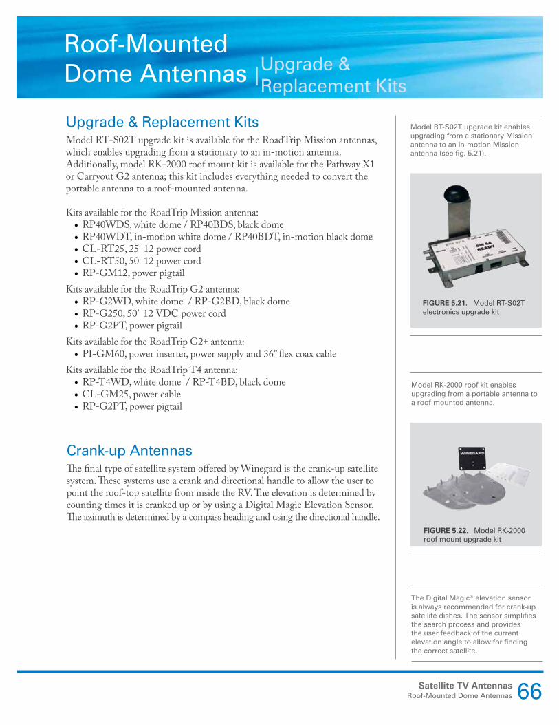
Model RK-2000 roof kit enables upgrading from a portable antenna to a roof-mounted antenna.
FIGURE 5.22. Model RK-2000 roof mount upgrade kit
The Digital Magic® elevation sensor is always recommended for crank-up satellite dishes. The sensor simplifies the search process and provides the user feedback of the current elevation angle to allow for finding the correct satellite.
Satellite TV AntennasRoof-Mounted Dome Antennas 66

Satellite TV AntennasRoof-Mounted Dome Antennas67