Embed Size (px)
Citation preview
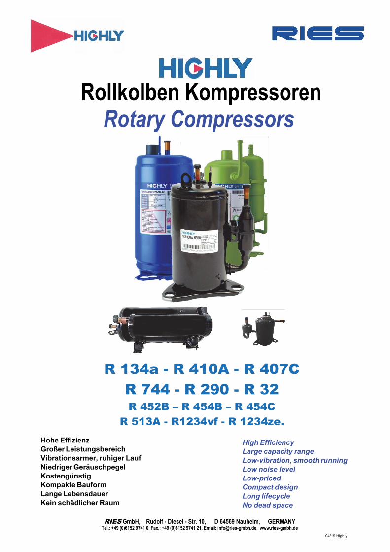
Rollkolben Kompressoren
Rotary Compressors
Hohe Effizienz Großer Leistungsbereich Vibrationsarmer, ruhiger Lauf Niedriger Geräuschpegel Kostengünstig Kompakte Bauform Lange Lebensdauer Kein schädlicher Raum
High Efficiency Large capacity range Low-vibration, smooth running Low noise level Low-priced Compact design Long lifecycle No dead space
RIES GmbH, Rudolf - Diesel - Str. 10, D 64569 Nauheim, GERMANY Tel.: +49 (0)6152 9741 0, Fax.: +49 (0)6152 9741 21, Email: [email protected], www.ries-gmbh.de
04/19 Highly
R 134a - R 410A - R 407C R 744 - R 290 - R 32 R 452B – R 454B – R 454C
R 513A - R1234yf - R 1234ze,

Modell Identifikation
Beispiel /Example A S L 145 S V - C 7L U *
Kältemittel/Verwendung Refrigerant/Use
Anzahl Zylinder Number of Cylinder
Serie / Series
Besondere Spezifikation Special Specification
Winkel φ Dreieckfuß zu Abschei- der / Angle φ of Triangle Base &
Accumulator
Hubvolumen / Displacement
Kompressor Leistungsskala / Compressor performance scale Spannung / Power Start Methode
Abmessung Abscheider Dimension Accumulator
C Standard R 100V/100-110V,50/60Hz Starting Method Kompressor Fußausfg Compressor Base Typ
S Hochleistung / High Efficiency R/U Super Hochlstg / Super High Efficiency G Niedrig Spannungsstart / Low Voltage start M D
W 110/115-120V,60Hz S 200V/200-220V, 50/60Hz N 208-230, 60Hz V 220V 220-240, 50Hz G 220V, 60Hz T 230V, 50/60Hz H 265-277, 60Hz C 380-400, 50/60Hz A AC Inverter D DC Inverter
- KP (1 ᴓ) 1 KT (1 ᴓ) 2 KR (1 ᴓ) 3 K (1 ᴓ) 4 KQ (1 ᴓ) 5 KN ( 1 ᴓ)
Anwendungsbereiche Applications
+ Industrielle Schaltschranktechnik + Entfeuchtung + Medizintechnik + Drucklufttechnik + Bautrocknung + Getränkeautomaten + Wärmepumpen + Klimageräte + Labor-/Prüfgeräte
+ Industrial cabinets + Dehumidification + Medical technology + Compressed air technology + Dehumidification units + Vending maschine + Heat pump + Air conditioners + Laboratory and testing equipment
Inhalt Content Seite/Page
Model Identifikation Model identification------------------------ 2-3
Schnittzeichnung/-modell Cut away view Model…………………. 3
Betriebsbedingungen Operating conditions………………….. 4
Einsatzgrenzen Limitation of use……………………….. 4
Produkt- und LeistungstabelleProduct- and Capacity data
Rotary B R 134a………………………………….. 5-6
Rotary WHP BUV R 134a, R 1234yf, R 513A, R 410A…. 7
Rotary WHP R 134a, R 513A, R 1234yf, R1234ze.. 8
Rotary C R 407C…………………………………. 9
Rotary A R 410A…………………………………. 10
Rotary DC /BLDC (Inverter) R 410A, R 134a, R 513A, R 407C…... 11
Rotary WHP 220/380/DC R 410A…………………………………. 12
Rotary WHP DC/BLDC/(Inv) R410 A, R 452B, R 454B, R 454C …. 13
Rotary WHP R 290 (Propan)………………………… 14
Rotary liegend (horiz) R 290 (Propan)………………………… 14
Rotary WHP DC/BLDC (Inv) R 290 (Propan)………………………… 15
R 290 (Propan)………………………… 16
17
18
19
20
Rotary PDD horizontal
Rotary Y + GS
Rotary D horizontal
Rotary Mini BSW
Zubehör
Drehzahlregler E1045/1145
R 744 (CO2), R 32……………………..
R404A, R407F…………………………
R 134a, R 600………………………….
Accessories ……………………….….
DC-Rotary Drehzahlregelung
Speed Controller E1045/1145..............
BLDC Inverter…………………............. 23
21-22
Highly Die bessere Lösung 1. Gegenüber Hubkolben Kompressoren
Niedrigere Leistungsaufnahme bei gleicher Kälteleistung Höhere Leistungszahl und damit geringere Betriebskosten Braucht eine um 40% geringere Aufstellungsfläche 25% geringeres Gewicht, 40% weniger Bauteile Geringerer Ölwurf Niedrigere Anfälligkeit für Flüssigkeitsschläge durch Accumulator Konstruktiv besser gegen Rückkondensation geschützt
2. Gegenüber anderen Rollkolben KompressorenFür alle Anwendung und Bereiche den passenden Verdichter Auch im Preis überzeugend. Hohe Qualität, Zuverlässigkeit und Akzeptanz was auch durch eine Produktion von 18 Millionen Kompressoren pro Jahr bewiesen wird. Auch für kleinere Serien und für Austausch lieferbar.
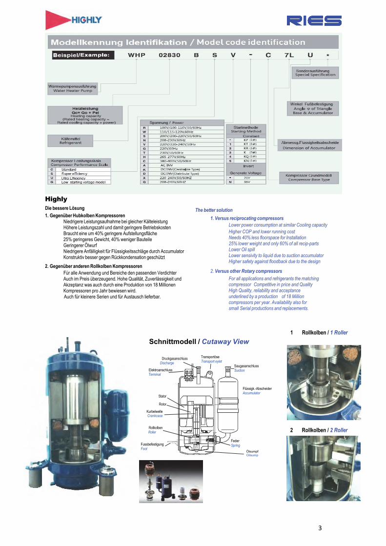
Schnittmodell / Cutaway View 1 Rollkolben / 1 Roller
Druckgasanschluss Discharge
Elektroanschluss Terminal
Stator
Rotor
Kurbelwelle Crankcase
Rollkolben Roller
Transportöse Transport eylet
Saugasanschluss Suction
Flüssigk.-Abscheider Accumulator
2 Rollkolben / 2 Roller
Fussbefestigung Foot
Feder Spring
Ölsumpf Oilsump
The better solution
1. Versus reciprocating compressorsLower power consumption at similar Cooling capacity Higher COP and lower running cost Needs 40% less floorspace for Installation 25% lower weight and only 60% of all recip-parts Lower Oil spill Lower sensivity to liquid due to suction accumulator Higher safety against floodback due to the design
2. Versus other Rotary compressors
For all applications and refrigerants the matching compressor Competitive in price and Quality High Quality, reliability and acceptance underlined by a production of 18 Million compressors per year. Availability also for small Serial productions and replacements.
3
Operation standards and operational limits Refrigerant The HFC-134a (CH2FCF3) refrigerant must be used. Refrigerant R-134a
more than 99.95% in pure should be used for apparatus.
Evaporating temperature range -10°C to +25°C (14°F to 77°F), (1,0 – 5,67 bar ). The lower limit of this temperature may drop to -20°C (-4°F) during the start of a heating operation (2- 3 min) or during the transitional period between cooling/heating selection with the heatp.
Condensing temperatur range The range is 28°C to 70°C (82,4°F to 158°F ) (6,3 -20,2 bar ) Compression ratio This should be 8 or less.
Discharge gas temperature
Not exceed 115°C (239°F), This temperature should be measured at the surf - ace of the heat-insulated discharge pipe at 120 mm distance from the shell surface.
Suction gas temperature The suction gas´s overheat must be over 0°C (32° F) and the gas must be used on condition that discharge gas temperature is satisfied.
Motor wiinding temperature Not exceed 125°C (257°F).
Supply voltage (during operation)
The compressor must be operated on within the range of rated voltage ± 10%. The operating voltage shall be the terminal voltage of the compressor during operation.
Starting Voltage A voltage of 85% or more of the rated voltage shall be supplied at start-up. Provided the rated voltage 208-230V, the regulation must be within -5 % for 208 V +10% for 230V. The operating voltage shall be the terminal voltage of the compressor when the voltage drops due to starting current.
On / OFF cycle The ON/OFF cycle shall be a maximum of 6 times a hour. The OFF period shall extend from Start until the high/low pressure is balanced, and balanced start-up shall be the norm. Running time 3 min– idle 3 min.
Amount of refrigerant Depending on the different Sizes of the compressors (see compressor info) Start/Stop Operation cycle
The refrigeration, air conditioning, heat pump unit should be designed for < 170 000 operation cycles
Pipe connections The piping must be designed so that no damage will result from transporting and the ON/OFF of the compressor. At starting and stopping: 34 N/mm2 (3,5 kg/mm2 or less During operation: 17,7 N/mm2 (1,8kg/mm2) or less
Motorprotection Dome mount type: Connect the wires properly and mount the box on the top of the compressor. Remote type: Connect the wires properly and mount inside the equipment. Max. ambienttemp 60°C (140°F)
Starting/Operation capacitor Use only capacitors with recommended capacity and voltage.
Isolation of compressor The isolation restistance should be >10 MOhm between power terminals and ground (or housing). Also between the terminals itself.
Dielectric Resistance
A 50 or 60 Hz potential like stated below should be existent between the parts with and without voltage. 1000 V for 1 minute or 1200 V for 1 sec (Nominal 100 -110 V) 1500 V for 1 minute or 1800 V for 1 sec (Nominal 200 -240 V) 2000 V for 1 minute or 2400 V for 1 sec (Nominal 346 -486 V)
Density test of compressor Test pressure: 2,74 MPa (28 kg/cm“) -for R134a compressors
Dryness The supplied compressor is dry inside. The remaining humidity, measured by the MELCO operation should be less than 120 mg.
Transport The compressor is secured against vibration and collision during a normal transport
4
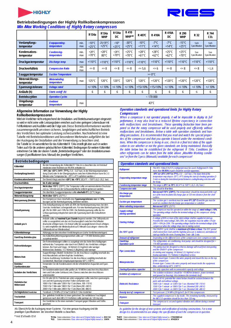
Betriebsbedingungen der Highly Rollkolbenkompressoren Min /Max Working Conditions of Highly Rotary compressors
R134a R134a WHP
R134a DC
R 410 WHP** R 407C R 410A
R 410A DC
R 290 WHP R 32 R 744
CO2
Verdampfungs- temperatur
Evapaporating- temperature
min. max
-10°C +25°C
-25/-30°C +25°C
-10° +25°C
-30°C +25°C
-10°C +11°C
-7°C +14°C
-7°C +14°C
-15°C +25°C
Sieh Spezifikation
Sieh Spezifikation
Kondensations- temperatur
Condensing- temperature
min. max
+28°C +70°C
+28°C 80°C
+28°C +70°C
+25°C +70°C
+28°C +61°C
+28°C +62°C
+25°C +62°C
+25°C +70°C
See Spezification
See Spezification
Druckgastemperatur Discharge temp max +110°C +110°C +110°C +110°C +110°C +110°C +110°C +110°C +110°C +110°C
Druckverhältnis Compression Ratio min max <= 8 <= 8 <= 8 <= 8 <= 5,6 <= 6 <= 8 <= 8 <= 8 >1,8
Sauggastemperatur Suction Temperature >= 0°C Motorwicklungs- temperatur
Motorwinding temperature max 125°C 120°C 120°C 120°C 120°C +120°C +120°C +120°C +120°C +120°C
Spannungstoleranz Voltage rated +/- 10% +/- 10% +/- 10% +/- 10% +15/-10% +15/-10% +/- 10% +/- 10% +/- 10% +/- 10% Anläufe (h) Starts on/off (h) 6 6 6 6 6 6 6 6 6 6 Betriebszyklen Operation Cycles < 170 000 Umgebungs temperatur
Ambient temperature max 43°C
Allgemeine Information zur Verwendung der Highly Rollkolbenkompressoren Wird ein Verdichter nicht entsprechend der Installation- und Betriebsanweisungen eingesetzt so wird er nicht seine volle Leistungsdaten erreichen auch eine geringere Lebensdauer mit Fehlfunktionen und Ausfällen wird die Folge sein. Diese Betriebsinformationen wurden zusammengestellt um einen sicheren, langlebigen und wirtschaftlichen Betrieb des Verdichters bei optimaler Leistung sicherzustellen. Nachstehend ist eine Tabelle mit Betriebskonditionen und besonderen Merkmalen aufgeführt die bei der Auslegung der Installation und der Verwendung zu beachten sind. Die Tabelle ist im wesentlichen für das Kältemittel R 134a erstellt gilt aber auch in weiten Teilen auch für die anderen gebräuchlichen Kältemittel. Bedingungen für weitere Kältemittel entnehmen Sie bitte der oberen Tabelle „Betriebsbedingungen“ oder den Installationsanwei- sungen (Spezifikationen bzw. Manual) des jeweiligen Verdichters.
Operation standards and operational limits for Highly Rotary Compressors When a compressor is not operated properly, it will be impossible to display its full performance, it may also lead to a reduced lifetime expectancy in connection with malfunctions and breakdowns. These operating Instruction have been pre- pared so that the rotary compressor will be used properly and efficiently without malfunctions and breakdowns. Below a table with operation standards and han- dling precautions. It is recommended that you read and watch the special proper- ties of the compressor and that you operate it based under the mentioned condi- tions. When the compressor is being in use, check in a final test data of the appli- cation to see whether or not the given standards are being maintained. Basically the table below has be establlished for the refrigerant R 134a. Conditions for other refrigerants can be taken from the table above „Max/Min Working conditi- ons“ or from the Specs (Manuals) available for each compressor!
Betriebsbedingungen Kältemittel Bei der Verwendung des Kältemittel R 134a ist zu beachten das im Kreislauf
mindesten einer Reinheit von 99,95% enthalten ist
Verdampfungsbereich -10°C bis +25°C (14°F- 77°F), (1,0 – 5,67 bar). In der Wärmepumpenanwen- dung (Start) oder in der Übergangsphase zwischen Kühlen/Heizen kann für 2-3 Minuten eine Temperatur bis - 20°C (-4°F) gefahren werden. /
Kondensationsbereich Der Bereich liegt zwischen +28°C bis +70°C (82,4°F – 158°F) (6,3 -20,2 bar) Druckverhältnis bis 8 oder weniger
Druckgastemperatur Nicht über 115°C (239°F). Die Temperatur sollte am wärmeisolierten Druckstut- zen ca. 120 mm von der Gehäuseoberfläche entfernt gemessen werden
Sauggastemperatur Die überhitzte Sauggastemperatur sollte oberhalb 0°C (32°F) liegen Motorwicklungstemp Nicht über 125°C (257°F) /
Netzspannung (Betrieb) Der Kompressor muss innerhalb einer Spannungstoleranz von +/- 10%, bezogen auf die Nominalspannung, betrieben werden.
Anlaufspannung
Eine Anlaufspannung von mehr als 85% der Nominalspannung muss bei dem Start des Verdichters sichergestellt sein. Für eine Nominalspannung 208-230V gilt -5% für 208V und +10% für 230V. Die Betriebsspannung sollte der An- schlussspannung entsprechen wenn die Spannung durch den Anlaufstrom absinkt.
Anläufe pro h
Anläufe sollte auf maximal 6 pro Stunde begrenzt werden. Die Stillstandszeit sollte so ausgedehnt sein das ein Druckausgleich zwischen Hoch/Nieder druckseite erfolgen kann. Ein Anlauf sollte bei ausgeglichenem Druck erfolgen. Es wird empfohlen die Mindestlaufzeit auf 3 Minuten auszulegen– ebenso die Stillstandszeit vor Wiederanlauf.
Kältemittelmenge Abhängig von den einzelnen Verdichtergrössen (siehe Verdichterunterlagen)
Start/Stop Betriebszylus Die Kälte/Klima/Wärmepumpeneinheit sollte auf < 170 000 Betriebszyklen ausgelegt werden
Rohrverbindungen Die Rohrverbindungen sollten so ausgelegt sein das keine Beschädigungen während des Transportes oder durch ein EIN/AUS des Verdichters erfolgen können. Bei Start und Stopp : 34 N/mm2 (3,5 kg/mm2 oder weniger Während des Betriebs: 17,7 N/mm2 (1,8kg/mm2) oder weniger
Motorschutz Kappenförmiges Modell: Verdrahten Sie die Anschlüsse sorgfältig innerhalb des Anschlussdeckels auf dem Kopf des Verdichters. Externe Ausführung: Verdrahten Sie die Anschlüsse sorgfältig innerhalb der Geräteinheit. Maximale Umgebungstemperatur 60°C (140°F)
Betriebs/ Startkondensator
Verwenden Sie die Kondensatoren mit der erforderlichen Kapazität und Span- nung.
Isolation des Verdichters Der Isolationswiderstand sollte größer als 10 MOhm zwischen Anschlussklem- men und Erde (oder Gehäuse) sein. Ebenso zwischen den Anschlüssen untereinander
Dielektrischer Widerstand
Ein 50 oder 60 Hz Potential wie unten angegeben sollte zwischen spannungslo- sen und mit Spannung versehen Teilen vorhanden sein 1000 V für 1 Min oder 1200 V für 1 Sek (Nom. 100 -110 V) 1500 V für 1 Min oder 1800 V für 1 Sek (Nom.200 -240 V) 2000 V für 1 Min oder 2400 V für 1 Sek (Nom 346 -486 V)
Dichtigkeitstest Verdichter Testdruck: 2,74 MPa (27,4 bar“) Gilt für R 134a Verdichter
Trockenheit Der gelieferte Verdichter ist innen getrocknet. Die verbliebene Feuchtigkeit gemessen nach dem MELCO Verfahren sollte geringer als 120 mg sein.
Transport Der Verdichter ist für einen normalen Transport gegen Vibration und Stöße. gesichert
Als Übersicht für die Auslegung neuer Systeme. Für eine genaue Auslegung sind die jeweiligen Spezifikationen der einzelnen Modelle zu beachten.
As guideline for the design of new systems and verification of existing constructions. For a new design it is recommended to use always the specification of each the compressor in question.
**mit EVI/with EVI *R134a Daten entnommen / Data taken out of Original Highly manual i.e. BSD 122 *R407C Daten entnommen / Data taken out of Original Highly manual i.e. CTHU33WC6-U*R22 Daten entnommen / Data taken out of Original Highly manual i.e. SD074 *R410A Daten entnommen / Data taken out of Original Highly manual i.e. ATH325CV
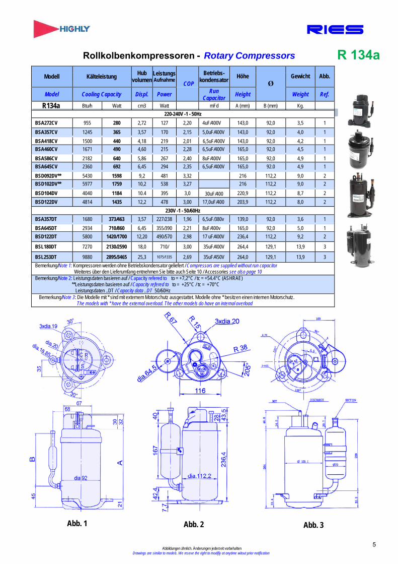
Rollkolbenkompressoren - Rotary Compressors R 134a
Modell Kälteleistung Hub volumen
Leistungs Aufnahme
COP
Betriebs- kondensator Höhe
Ø Gewicht Abb.
Model Cooling Capacity Displ. Power RunCapacitor Height Weight Ref.
R134a Btu/h Watt cm3 Watt mFd A (mm) B (mm) Kg. 220-240V -1 - 50Hz
BSA272CV 955 280 2,72 127 2,20 4uF/400V 143,0 92,0 3,5 1 BSA357CV 1245 365 3,57 170 2,15 5,0uF/400V 143,0 92,0 4,0 1 BSA418CV 1500 440 4,18 219 2,01 6,5uF/400V 143,0 92,0 4,2 1 BSA460CV 1671 490 4,60 215 2,28 6,5uF/400V 165,0 92,0 4,5 1 BSA586CV 2182 640 5,86 267 2,40 8uF/400V 165,0 92,0 4,9 1 BSA645CV 2360 692 6,45 294 2,35 6,5uF/400V 165,0 92.0 4,9 1 BSD092DV** 5430 1598 9,2 481 3,32 216 112,2 9,0 2 BSD102DV** 5977 1759 10,2 538 3,27 216 112,2 9,0 2
BSD104DV 4040 1184 10.4 395 3,0 30uF/400 220,9 112,2 8,7 2 BSD122DV 4814 1435 12,2 478 3,00 17,0uF/400 203,9 112,2 8,0 2
230V -1 - 50/60Hz BSA357DT 1680 373/463 3,57 227/238 1,96 6,5uF/380v 139,0 92,0 3,6 1 BSA645DT 2934 710/860 6,45 355/390 2,21 8uF/400v 165,0 92,0 5,0 1 BSD122DT 5800 1420/1700 12,20 490/570 2,98 17 uF/400V 236,4 112,2 9,2 2
BSL180DT 7270 2130/2590 18,0 710/ 3,00 35uF/400V 264,4 129,1 13,9 3
BSL253DT 9880 2895/3465 25,3 1075/1335 2,69 35uF/450V 264,0 129,1 13,9 3 Bemerkung/Note 1: Kompressoren werden ohne Betriebskondensator geliefert / Compressors are supplied without run capacitor
Weiteres über den Lieferumfang entnehmen Sie bitte auch Seite 10 / Accessories see also page 10 Bemerkung/Note 2: Leistungsdaten basieren auf / Capacity refered to to = +7,2°C / tc = +54.4°C (ASHRAE)
**Leistungsdaten basieren auf / Capacity refered to to = +25°C / tc = +70°C Leistungsdaten ..DT / Capacity data ..DT 50/60Hz
Bemerkung/Note 3: Die Modelle mit * sind mit externem Motorschutz ausgestattet. Modelle ohne * besitzen einen internen Motorschutz. The models with * have the external overload. The other models do have an internal overload
Abb. 1 Abb. 2 Abb. 3
5 Abbildungen ähnlich. Änderungen jederzeit vorbehalten
Drawings are similar to models. We reseve the right to modifiy at anytime witout prior notification
Konden
sationstemp / Conden
sing Te
mp
Verdampfungstemp / Evaporating Temp °C
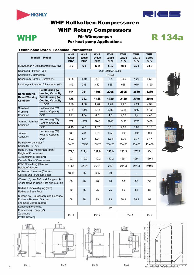
WHP Rollkolben-Kompressoren WHP Rotary Compressors
Für Wärmpumpen For heat pump Applications
R 134a
WHP 00680 BUV
WHP 00930 BUV
WHP 01900 BUV
WHP 02250 BUV
WHP 02830 BUV
WHP 03970 BUV
WHP 05100 BUV
4,6 6,3 12,2 14,5 18,0 25,3 33,6
0,85 1,10 2,2 2,4 3,05 4,20 5,53
189 238 450 525 665 910 1190
Heizleistung (W) Heating Capacity
714 951 1895 2205 2805 3860 5230
Kälteleistung (W) Cooling Capacity
525 713 1445 1680 2140 2950 4040
COP 3,78 4,00 4,20 4,20 4,22 4,24 4,39
Heizleistung (W) Heating Capacity
746 1003 1975 2280 2915 4040 5490
COP 3,91 4,04 4,3 4,3 4,32 4,4 4,46
Heizleistung (W) Heating Capacity
871 1174 2240 2705 3435 4785 6460
COP 4,49 4,7 4,87 5,01 4,99 5,09 5,13
Heizleistung (W) Heating Capacity
538 741 1370 1650 2095 2915 3990
COP 3,02 3,14 3,24 3,33 3,30 3,37 3,47
6/450 10/450 15/420 20/420 25/420 35/450 45/450
172,6 217,4 237,9 242,9 292,5 287,5 304
92 112.2 112.2 112.2 129.1 129.1 139.1
141,1 220,4 265,4 286 241,3 241,3 249,9
18.85 65 60.5 80 – – –
60 90 90 90 88 85 90
60 75 75 75 85 88 88
68 98 93 93 88,9 88,9 94
Pic 1 Pic4ZeichnungProfile Drawing
Pic 2 Pic 3
≤80
Betriebskondensator / Capacitor(uF/V)Höhe (A) des Verdichters (mm)Height of CompressorAußendurchm. (B)(mm)Outside Dia. of Compressor
Höhe Sauleitung (C)(mm)Height of Suction
Außendurchmesser (D)(mm)Outside Dia. of Accumulator
Winkel(°)zw Fuß und SauganschlAngel between Base Foot and Suction
Radius Fußbefestigung (mm)Radius of Base Foot
Distanz zw. Sauganschl und Gehäuse Distance Between Suction and Shell Centre (L)(mm)
Kondensationstemp.Condensing Temp.(℃)
Winter Condition
Technische Daten Technical Parameters
Modell / Model
Hubvolumen / Displacement (CC/rev)
Spannung / Power Type 220~240V/1/50Hz
Kältemittel / Refrigerant R134a
Nennstrom Rated / Current (A)
Leistungsaufnahmen / Rate Input (W)
Nennleistung / Rated Working Condition
Standard Working Condition
Somm / Summer Condition
WHP
6
WHP00930
WHP01900
WHP05100
Kon
dens
aton
stem
p / C
ond.
tenp
. °C
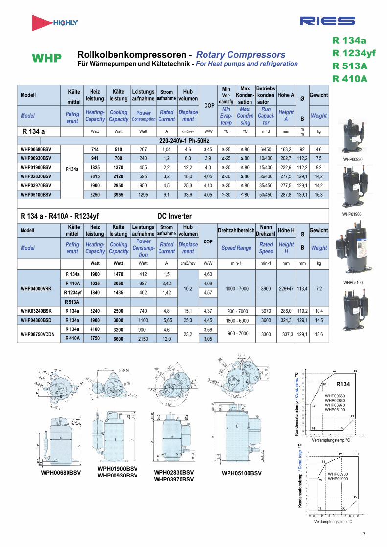
Rollkolbenkompressoren - Rotary Compressors Für Wärmepumpen und Kältetechnik - For Heat pumps and refrigeration
Modell Kälte
mittel
Heiz leistung
Kälte leistung
Leistungs aufnahme
Strom aufnahme
Hub volumen
COP
Min Ver-
dampfg
Max Konden- sation
Betriebs konden sator
Höhe AØ
B
Gewicht
Model Refrig erant
Heating- Capacity
Cooling Capacity
Power Consumption
Rated Current
Displace ment
Min Evap- temp
Max. Conden
sing
Run Capaci-
tor
Height A
Weight
R 134 a Watt Watt Watt A cm3/rev W/W °C °C mFd mm m m
kg
220-240V-1 Ph-50HzWHP00680BSV
R134a
714 510 207 1,04 4,6 3,45 ≥-25 ≤ 80 6/450 163,2 92 4,6
WHP00930BSV 941 700 240 1,2 6,3 3,9 ≥-25 ≤ 80 10/400 202,7 112,2 7,5
WHP01900BSV 1825 1370 455 2,2 12,2 4,0 ≥-30 ≤ 80 15/400 232,9 112,2 9,2
WHP02830BSV 2815 2120 695 3,2 18,0 4,05 ≥-30 ≤ 80 35/400 277,5 129,1 14,2
WHP03970BSV 3900 2950 950 4,5 25,3 4,10 ≥-30 ≤ 80 35/450 277,5 129,1 14,2
WHP05100BSV 5250 3955 1295 6,1 33,6 4,05 ≥-30 ≤ 80 50/450 287,8 139,1 16,3
R 134 a - R410A - R1234yf DC Inverter
ModellKälte
mittel Heiz
leistungKälte
leistungLeistungs aufnahme
Strom aufnahme
Hub volumen
COP
Drehzahlbereich Nenn Drehzahl Höhe H
Ø
B
Gewicht
ModelRefrig erant
Heating- Capacity
Cooling Capacity
Power Consump-
tion
Rated Current
Displace ment
Speed RangeRated Speed
Height H
Weight
Watt Watt Watt A cm3/rev W/W min-1 min-1 mm mm kg
WHP04000VRK
R 134a 1900 1470 412 1,5
10,2
4,60
1000 - 7000 3600 226+47 113,4 7,2R 410A 4035 3050 987 3,42 4,09
R 1234yf 1840 1435 402 1,42 4,57
R 513A
WHK03240BSK R 134a 3240 2500 740 4,8 15,1 4,37
900 - 7000
3970 286,0 119,2 10,4
WHP04860BSD R 134a 4900 3800 1100 5,65 25,3 4,45 3600 324,3 129,1 14,5
WHP08750VCDN R 134a 4100 3200 900 4,6
23,2 3,56
3300 337,3 129,1 13,6 R 410A 8750 6600 2150 12,0 3,05
Kon
dens
aton
stem
p. /
Con
d. te
np. °
C
WHP00930 WHP01900
WHP
WHP00680 WHP02830 WHP03970 WHP05100
Verdampfungstemp.°C
R 134a R 1234yf R 513A R 410A
R134
WPH00680BSV WPH01900BSV WHP00930BSV WPH02830BSV
WHP03970BSV WPH05100BSV
Verdampfungstemp.°C
7
900 - 7000
1800 - 6000
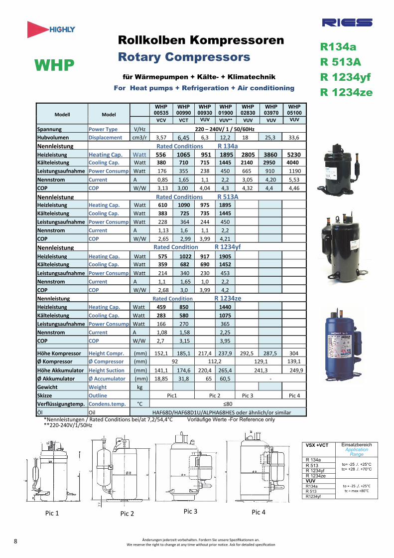
Modell Model
WHP 00535
WHP 00990
WHP 00930
WHP 01900
WHP 02830
WHP 03970
WHP 05100
VCV VCT VUV VUV** VUV VUV VUV
Spannung Power Type V/Hz 220 – 240V/ 1 / 50/60HzHubvolumen Displacement cm3/r 3,57 6,45 6,3 12,2 18 25,3 33,6
Nennleistung Rated Conditions R 134aHeizleistung Heating Cap. Watt 556 1065 951 1895 2805 3860 5230 Kälteleistung Cooling Cap. Watt 380 710 715 1445 2140 2950 4040
Leistungsaufnahme Power Consump Watt 176 355 238 450 665 910 1190
Nennstrom Current A 0,85 1,65 1,1 2,2 3,05 4,20 5,53
COP COP W/W 3,13 3,00 4,04 4,3 4,32 4,4 4,46
Nennleistung Rated Conditions R 513AHeizleistung Heating Cap. Watt 610 1090 975 1895
Kälteleistung Cooling Cap. Watt 383 725 735 1445
Leistungsaufnahme Power Consump Watt 228 364 244 450
Nennstrom Current A 1,13 1,6 1,1 2,2
COP COP W/W 2,65 2,99 3,99 4,21
Nennleistung Rated Condition R 1234yf
Heizleistung Heating Cap. Watt 575 1022 917 1905
Kälteleistung Cooling Cap. Watt 359 682 690 1452
Leistungsaufnahme Power Consump Watt 214 340 230 453
Nennstrom Current A 1,1 1,65 1,0 2,2
COP COP W/W 2,68 3,0 3,99 4,2
Nennleistung Rated Condition R 1234zeHeizleistung Heating Cap. Watt 459 850 1440
Kälteleistung Cooling Cap. Watt 283 580 1075
Leistungsaufnahme Power Consump Watt 166 270 365
Nennstrom Current A 1,08 1,58 2,25
COP COP W/W 2,7 3,15 3,95
Höhe Kompressor Height Compr. (mm) 152,1 185,1 217,4 237,9 292,5 287,5 304
Ø Kompressor Ø Compressor (mm) 92 112,2 129,1 139,1
Höhe Akkumulator Height Suction (mm) 141,1 174,6 220,4 265,4 241,3 249,9
Ø Akkumulator Ø Accumulator (mm) 18,85 31,8 65 60,5 ‐
Gewicht Weight kg
Skizze Outline Pic1 Pic 2 Pic 3 Pic 4
Verflüssigungtemp. Condens.temp. °C ≤80
Öl Oil HAF68D/HAF68D1U/ALPHA68HES oder ähnlich/or similar *Nennleistungen / Rated Conditions bei/at 7,2/54,4°C**220‐240V/1/50Hz
Änderungen jederzeit vorbehalten. Fordern Sie unsere Spezifikationen an. We reserve the right to change at any time without prior notice. Ask for detailed specification
VSX +VCT EinsatzbereichApplication
RangeR 134a
to= -25 ./. +25°C tc= +28 ./. +70°C
R 513 R 1234yf R 1234ze VUV
to = ‐25 ./. +25°C tc = max +80°C
R134a R 513 R1234yf
R134a R 513A R 1234yf R 1234ze
Rollkolben Kompressoren Rotary Compressors WHP
für Wärmepumpen + Kälte- + Klimatechnik For Heat pumps + Refrigeration + Air conditioning
8
Pic 1 Pic 3Pic 2 Pic 4
Vorläufige Werte -For Reference only
9 Abbildungen ähnlich. Änderungen jederzeit vorbehalten Drawings are similar to models. We reserve the right to modify at any time without prior
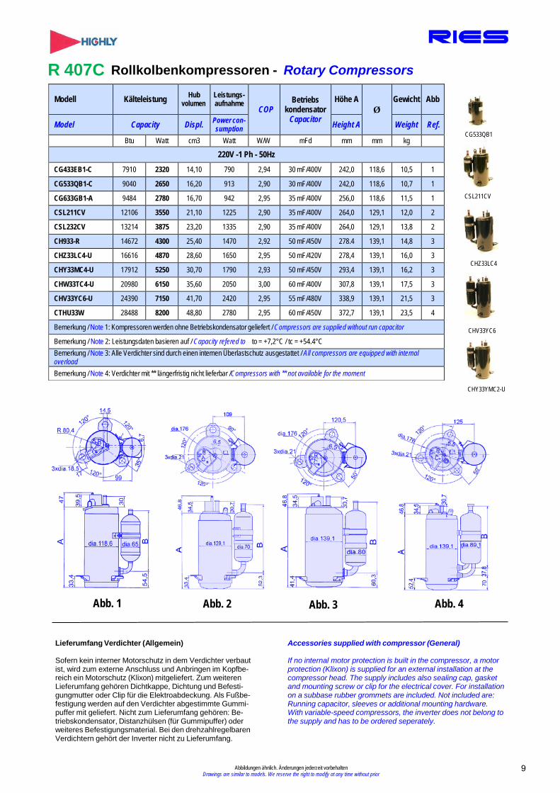
Modell Kälteleistung Hub volumen
Leistungs- aufnahme
COP Betriebs
kondensator Capacitor
Höhe A Ø
Gewicht Abb
Model Capacity Displ. Power con- sumption Height A Weight Ref.
Btu Watt cm3 Watt W/W mFd mm mm kg
220V -1 Ph - 50Hz CG433EB1-C 7910 2320 14,10 790 2,94 30 mF/400V 242,0 118,6 10,5 1
CG533QB1-C 9040 2650 16,20 913 2,90 30 mF/400V 242,0 118,6 10,7 1
CG633GB1-A 9484 2780 16,70 942 2,95 35 mF/400V 256,0 118,6 11,5 1
CSL211CV 12106 3550 21,10 1225 2,90 35 mF/400V 264,0 129,1 12,0 2
CSL232CV 13214 3875 23,20 1335 2,90 35 mF/400V 264,0 129,1 13,8 2
CH933-R 14672 4300 25,40 1470 2,92 50 mF/450V 278.4 139,1 14,8 3
CHZ33LC4-U 16616 4870 28,60 1650 2,95 50 mF/420V 278,4 139,1 16,0 3
CHY33MC4-U 17912 5250 30,70 1790 2,93 50 mF/450V 293,4 139,1 16,2 3
CHW33TC4-U 20980 6150 35,60 2050 3,00 60 mF/400V 307,8 139,1 17,5 3
CHV33YC6-U 24390 7150 41,70 2420 2,95 55 mF/480V 338,9 139,1 21,5 3
CTHU33W 28488 8200 48,80 2780 2,95 60 mF/450V 372,7 139,1 23,5 4
Bemerkung / Note 1: Kompressoren werden ohne Betriebskondensator geliefert / Compressors are supplied without run capacitor
Bemerkung / Note 2: Leistungsdaten basieren auf / Capacity refered to to = +7,2°C / tc = +54.4°C Bemerkung / Note 3: Alle Verdichter sind durch einen internen Überlastschutz ausgestattet / All compressors are equipped with internal overload Bemerkung / Note 4: Verdichter mit ** längerfristig nicht lieferbar /Compressors with ** not available for the moment
R 407C Rollkolbenkompressoren - Rotary Compressors
CG533QB1
CSL211CV
CHZ33LC4
CHV33YC6
CHY33YMC2-U
Abb. 1 Abb. 2 Abb. 3 Abb. 4
Lieferumfang Verdichter (Allgemein)
Sofern kein interner Motorschutz in dem Verdichter verbaut ist, wird zum externe Anschluss und Anbringen im Kopfbe- reich ein Motorschutz (Klixon) mitgeliefert. Zum weiteren Lieferumfang gehören Dichtkappe, Dichtung und Befesti- gungmutter oder Clip für die Elektroabdeckung. Als Fußbe- festigung werden auf den Verdichter abgestimmte Gummi- puffer mit geliefert. Nicht zum Lieferumfang gehören: Be- triebskondensator, Distanzhülsen (für Gummipuffer) oder weiteres Befestigungsmaterial. Bei den drehzahlregelbaren Verdichtern gehört der Inverter nicht zu Lieferumfang.
Accessories supplied with compressor (General)
If no internal motor protection is built in the compressor, a motor protection (Klixon) is supplied for an external installation at the compressor head. The supply includes also sealing cap, gasket and mounting screw or clip for the electrical cover. For installation on a subbase rubber grommets are included. Not included are: Running capacitor, sleeves or additional mounting hardware. With variable-speed compressors, the inverter does not belong to the supply and has to be ordered seperately.

Modell Kälteleistung Leistungs aufnahme
Model Capacity
Btu
Power consump-
tion
Watt Watt
Hub volu- men
Dis-placement
cm 3
COP
W/W 2 2 0 - 2 4 0 V - 1 - 5 0 H z
Bemerkung / Note 1: Kompressoren werden ohne Betriebskondensator geliefert / Compressors are supplied without run capacitor Weiteres über den Lieferumfang entnehmen Sie bitte auch Seite 10 / Accessories see also page 10
Bemerkung / Note 2: Leistungsdaten basieren auf / Capacity refered to to = +7,2°C / tc = +51.4°C
Bemerkung / Note 3: Die Modelle mit * sind mit externem Motorschutz ausgestattet. Modelle ohne * besitzen einen internen Motorschutz. Models with * have the external overload. The other models do have an internal overload.
R 410 A Rollkolbenkompressoren - Rotary Compressors
ASH264SV
Abb. 1 Abb. 2
Abb. 4
Abb. 3
Abbildungen ähnlich. Änderungen jederzeit vorbehalten10Drawings are similar to models. We reserve the right to modify at any time without prior notification
ASG80CV
Betriebs- Höhe H Ge- kondensator wicht Abb
Ø
Run Capacitor Height H Weight Ref
m Fd/V mm mm Kg .
ASG108CV
ASH218SV
ASG080CV* 6278 1840 679 8,0 2,71 30mF/400V 247,0 119,2 11,0 1
ASG108CV* 8701 2550 920 10,8 2,77 35mF/400V 247,0 119,2 11,0 1
ASL145SV 11489 3370 1160 14,0 2,90 35mF/450V 279,0 129,1 10,5 2
ASL155SV 12617 3700 1275 15,5 2,90 35mF/450V 279,0 129,1 10,5 2
ASL180SV 14834 4350 1500 18,0 2.90 35mF/450V 279,0 129,1 12,0 2
ASH201SV 16436 4820 1690 20,1 2,85 60mF/400V 298,5 140,1 13,5 3
ASH218SV 17664 5180 1786 21,8 2,90 60mF/400V 298,5 140,1 14,0 3
ASH264SV 21517 6310 2214 26,4 2,85 50mF/400V 298,5 140,1 15,5 3
ATH280CV 23393 6860 2382 28,0 2,88 60mF/450V 358,0 140,1 22,5 4
ATH290CV 24310 7125 2457 29,0 2,90 60mF/450V 358,0 140,1 22,5 4
ATH325CV 26462 7760 2723 32,5 2,85 60mF/450V 358,0 140,1 22,8 4
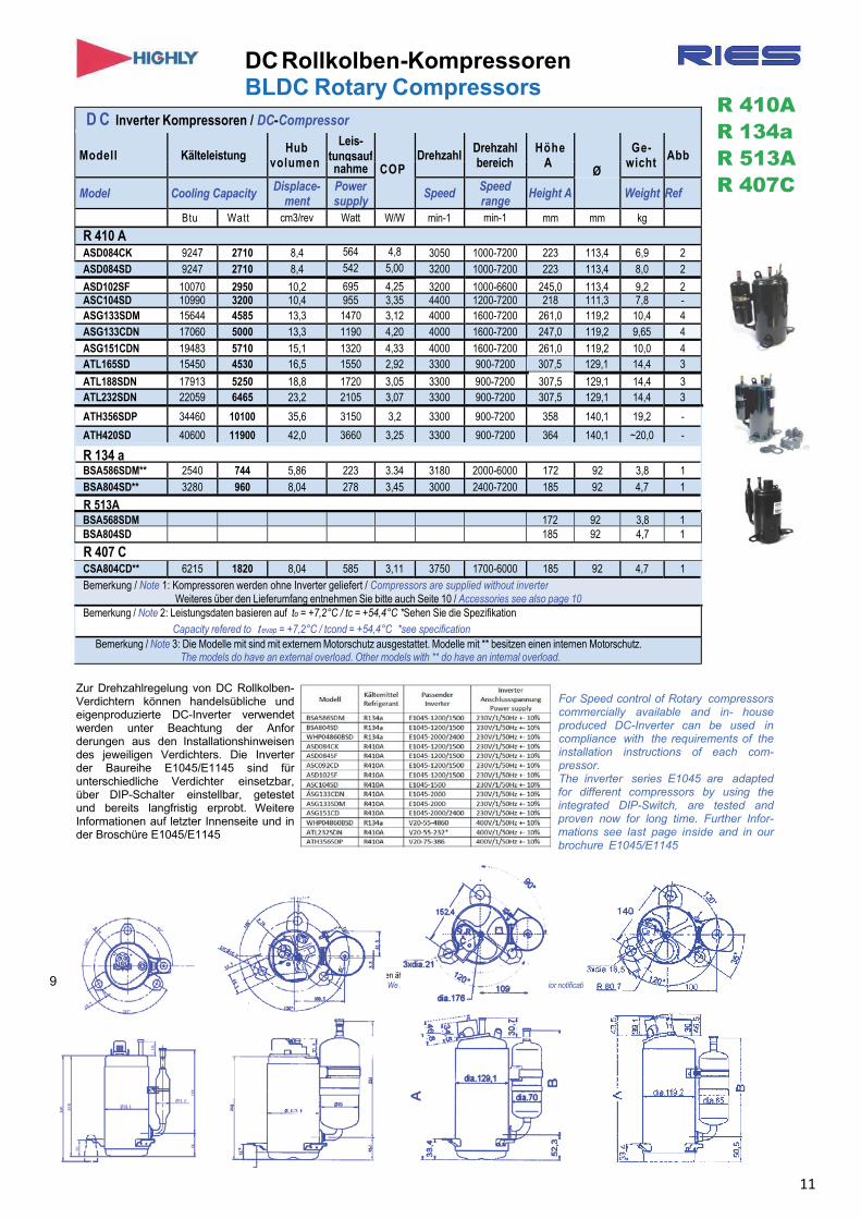
DC Rollkolben-Kompressoren BLDC Rotary Compressors
Zur Drehzahlregelung von DC Rollkolben- Verdichtern können handelsübliche und eigenproduzierte DC-Inverter verwendet werden unter Beachtung der Anfor derungen aus den Installationshinweisen des jeweiligen Verdichters. Die Inverter der Baureihe E1045/E1145 sind für unterschiedliche Verdichter einsetzbar, über DIP-Schalter einstellbar, getestet und bereits langfristig erprobt. Weitere Informationen auf letzter Innenseite und in der Broschüre E1045/E1145
For Speed control of Rotary compressors commercially available and in- house produced DC-Inverter can be used in compliance with the requirements of the installation instructions of each com- pressor. The inverter series E1045 are adapted for different compressors by using the integrated DIP-Switch, are tested and proven now for long time. Further Infor- mations see last page inside and in our brochure E1045/E1145
Abbildungen ähnlich. Änderungen jederzeit vorbehalten Drawings are similar to models. We reserve the right to modify at any time without prior notification
R 410A R 134a R 513A R 407C
9
D C Inverter Kompressoren / DC-Compressor
Modell Kälteleistung Hub
volumen
Leis- tungsauf
Drehzahl
Drehzahl bereich
Höhe A
Ø
Ge- wicht Abb
nahme COP
Model Cooling Capacity Displace- ment
Power supply
Speed Speed range
Height A Weight Ref
Btu Watt cm3/rev Watt W/W min-1 min-1 mm mm kg
R 410 A ASD084CK 9247 2710 8,4 564 4,8 3050 1000-7200 223 113,4 6,9 2 ASD084SD 9247 2710 8,4 542 5,00 3200 1000-7200 223 113,4 8,0 2
ASD102SF 10070 2950 10,2 695 4,25 3200 1000-6600 245,0 113,4 9,2 2 ASC104SD 10990 3200 10,4 955 3,35 4400 1200-7200 218 111,3 7,8 - ASG133SDM 15644 4585 13,3 1470 3,12 4000 1600-7200 261,0 119,2 10,4 4 ASG133CDN 17060 5000 13,3 1190 4,20 4000 1600-7200 247,0 119,2 9,65 4
ASG151CDN 19483 5710 15,1 1320 4,33 4000 1600-7200 261,0 119,2 10,0 4 ATL165SD 15450 4530 16,5 1550 2,92 3300 900-7200 307,5 129,1 14,4 3
ATL188SDN 17913 5250 18,8 1720 3,05 3300 900-7200 307,5 129,1 14,4 3 ATL232SDN 22059 6465 23,2 2105 3,07 3300 900-7200 307,5 129,1 14,4 3
ATH356SDP 34460 10100 35,6 3150 3,2 3300 900-7200 358 140,1 19,2 -
ATH420SD 40600 11900 42,0 3660 3,25 3300 900-7200 364 140,1 ~20,0 -
R 134 a BSA586SDM** 2540 744 5,86 223 3.34 3180 2000-6000 172 92 3,8 1 BSA804SD** 3280 960 8,04 278 3,45 3000 2400-7200 185 92 4,7 1
R 513A BSA568SDM 172 92 3,8 1 BSA804SD 185 92 4,7 1
R 407 C CSA804CD** 6215 1820 8,04 585 3,11 3750 1700-6000 185 92 4,7 1 Bemerkung / Note 1: Kompressoren werden ohne Inverter geliefert / Compressors are supplied without inverter
Weiteres über den Lieferumfang entnehmen Sie bitte auch Seite 10 / Accessories see also page 10 Bemerkung / Note 2: Leistungsdaten basieren auf to = +7,2°C / tc = +54,4°C *Sehen Sie die Spezifikation
Capacity refered to tevap = +7,2°C / tcond = +54,4°C *see specification Bemerkung / Note 3: Die Modelle mit sind mit externem Motorschutz ausgestattet. Modelle mit ** besitzen einen internen Motorschutz.
The models do have an external overload. Other models with ** do have an internal overload.
11
Verdampfungstemperatur /Evaporating Temp. °C
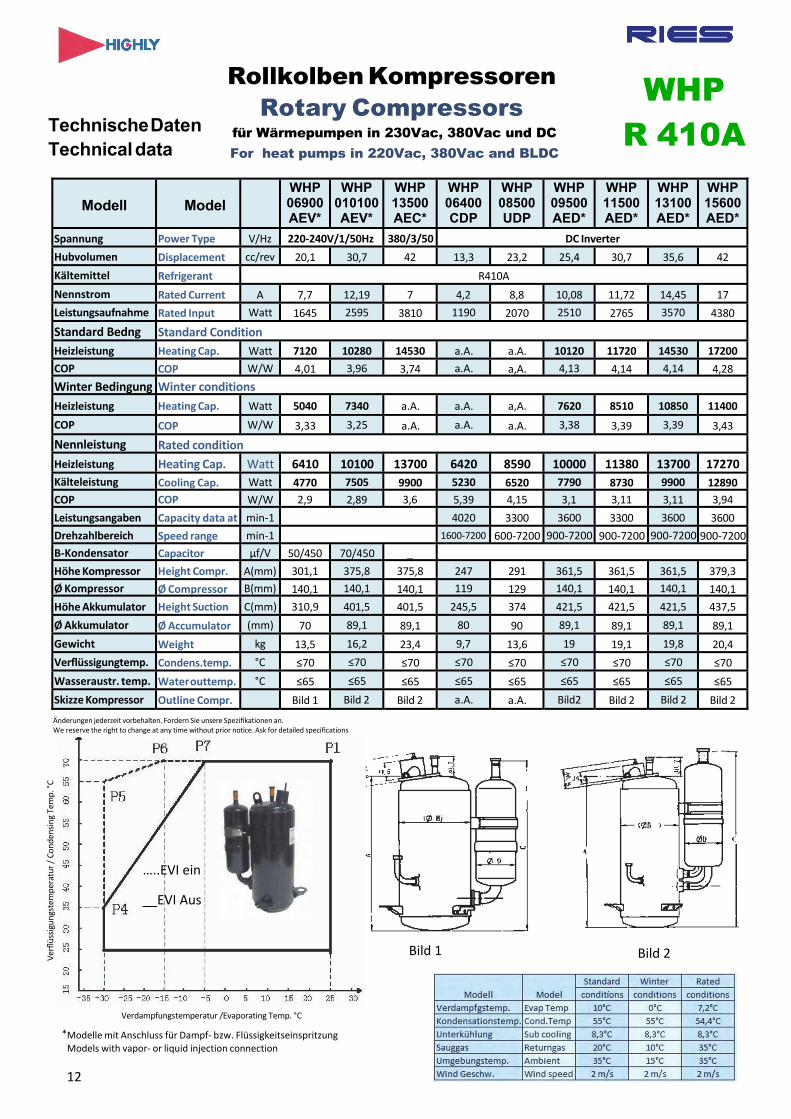
Technische Daten Technical data
Rollkolben Kompressoren Rotary Compressors
für Wärmepumpen in 230Vac, 380Vac und DC For heat pumps in 220Vac, 380Vac and BLDC
WHP R 410A
Modell Model WHP 06900 AEV*
WHP 010100AEV*
WHP 13500AEC*
WHP 06400 CDP
WHP 08500 UDP
WHP 09500 AED*
WHP 11500 AED*
WHP 13100AED*
WHP 15600AED*
Spannung Power Type V/Hz 220‐240V/1/50Hz 380/3/50 DC Inverter
Hubvolumen Displacement cc/rev 20,1 30,7 42 13,3 23,2 25,4 30,7 35,6 42
Kältemittel Refrigerant R410A
Nennstrom Rated Current A 7,7 12,19 7 4,2 8,8 10,08 11,72 14,45 17
Leistungsaufnahme Rated Input Watt 1645 2595 3810 1190 2070 2510 2765 3570 4380
Standard Bedng Standard Condition Heizleistung Heating Cap. Watt 7120 10280 14530 a.A. a.A. 10120 11720 14530 17200
COP COP W/W 4,01 3,96 3,74 a.A. a,A. 4,13 4,14 4,14 4,28
Winter Bedingung Winter conditions Heizleistung Heating Cap. Watt 5040 7340 a.A. a.A. a,A. 7620 8510 10850 11400
COP COP W/W 3,33 3,25 a.A. a.A. a.A. 3,38 3,39 3,39 3,43
Nennleistung Rated condition
Heizleistung Heating Cap. Watt 6410 10100 13700 6420 8590 10000 11380 13700 17270
Kälteleistung Cooling Cap. Watt 4770 7505 9900 5230 6520 7790 8730 9900 12890
COP COP W/W 2,9 2,89 3,6 5,39 4,15 3,1 3,11 3,11 3,94
Leistungsangaben Capacity data at min‐1 4020 3300 3600 3300 3600 3600
Drehzahlbereich Speed range min‐1 1600‐7200 600‐7200 900‐7200 900‐7200 900‐7200 900‐7200
B‐Kondensator Capacitor µf/V 50/450 70/450 _
Höhe Kompressor Height Compr. A(mm) 301,1 375,8 375,8 247 291 361,5 361,5 361,5 379,3
Ø Kompressor Ø Compressor B(mm) 140,1 140,1 140,1 119 129 140,1 140,1 140,1 140,1
Höhe Akkumulator Height Suction C(mm) 310,9 401,5 401,5 245,5 374 421,5 421,5 421,5 437,5
Ø Akkumulator Ø Accumulator (mm) 70 89,1 89,1 80 90 89,1 89,1 89,1 89,1
Gewicht Weight kg 13,5 16,2 23,4 9,7 13,6 19 19,1 19,8 20,4
Verflüssigungtemp. Condens.temp. °C ≤70 ≤70 ≤70 ≤70 ≤70 ≤70 ≤70 ≤70 ≤70
Wasseraustr. temp. Water outtemp. °C ≤65 ≤65 ≤65 ≤65 ≤65 ≤65 ≤65 ≤65 ≤65
Skizze Kompressor Outline Compr. Bild 1 Bild 2 Bild 2 a.A. a.A. Bild2 Bild 2 Bild 2 Bild 2
Verflüssigungstemperatur / Conden
sing Temp. °C
Bild 1 Bild 2
*Modelle mit Anschluss für Dampf‐ bzw. Flüssigkeitseinspritzung Models with vapor‐ or liquid injection connection
Änderungen jederzeit vorbehalten. Fordern Sie unsere Spezifikationen an. We reserve the right to change at any time without prior notice. Ask for detailed specifications
12
…..EVI ein
__EVI Aus
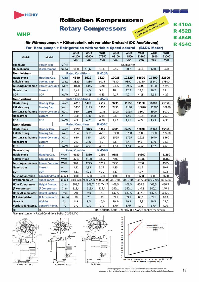
Modell Model
WHP 04200
WHP 05600
WHP 07850
WHP 09100
WHP 11500
WHP 13100
WHP 15600
WHP 23000
VRK VUK VUK VUK VSD VSD VSD VSD
Spannung Power Type V/Hz DC Inverter
Hubvolumen Displacement cm3/r 11,0 18,6 18,6 22,6 30,7 35,6 42,0 54,8
Nennleistung Rated Conditions R 410AHeizleistung Heating Cap. Watt 4340 5622 7820 10035 12320 14620 17400 22600Kälteleistung Cooling Cap. Watt 3320 4280 6015 7630 9390 11120 13240 17300
Leistungsaufnahme Power Consump Watt 1020 1345 1805 2405 2935 3500 4160 5290
Nennstrom Current A 3,45 4,5 5,5 10 12,3 14,2 16,2 21
COP COP W/W 4,25 4,18 4,33 4,17 4,2 4,18 4,18 4,27
Nennleistung Rated Conditions R 452BHeizleistung Heating Cap. Watt 4210 5470 7595 9735 11950 14180 16880 21950
Kälteleistung Cooling Cap. Watt 3230 4125 5860 7430 9140 10820 12900 16880
Leistungsaufnahme Power Consump Watt 980 1193 1735 2305 2815 3360 3990 5070
Nennstrom Current A 3,35 4,36 5,34 9,8 12,0 13,8 15,8 20,5
COP COP W/W 4,3 4,23 4,38 4,22 4,25 4,22 4,23 4,33
Nennleistung Rated Condition R 454C
Heizleistung Heating Cap. Watt 2990 3875 5365 6885 8455 10030 11940 15560
Kälteleistung Cooling Cap. Watt 1640 3020 4215 5360 6730 7800 9300 12200
Leistungsaufnahme Power Consump Watt 650 855 1150 1525 1725 2225 2640 3360
Nennstrom Current A 2,5 3,26 4,0 6,8 8,4 9,6 11,0 14,3
COP COP W/W 4,60 4,53 4,67 4,51 4,54 4,52 4,52 4,63
Nennleistung Rated Condition R 454BHeizleistung Heating Cap. Watt 4180 5380 7530 9855 14360 21150
Kälteleistung Cooling Cap. Watt 3210 4100 5815 7600 11080 16160
Leistungsaufnahme Power Consump Watt 970 1275 1715 2255 3280 4995
Nennstrom Current A 3,32 4,33 5,29 8,85 12,6 20,6
COP COP W/W 4,31 4,21 4,39 4,37 4,37 4,23
Leistungsangaben Capacity data at min‐1 3600 3600 3600 3600 3600 3600 3600 3600
Drehzahlbereich Speed range min‐1 1000‐7200 900‐7200 900‐7200 900‐7200 900‐7200 900‐7200 900‐7200 900‐6000
Höhe Kompressor Height Compr. (mm) 308,7 308,7 261,7+ 47 406,5 406,5 406,5 406,5 450,7
Ø Kompressor Ø Compressor (mm) 113,4 113,4 113,4 140,1 140,1 140,1 140,1 140,1
Höhe Akkumulator Height Suction (mm) 294 294 315 447,5 437,5 437,5 437,5 436,5
Ø Akkumulator Ø Accumulator (mm) 70 70 80 89,1 89,1 89,1 89,1 89,1
Gewicht Weight kg 8,9 9,5 10,0 19,24 19,3 19,3 19,5 22,0
Verflüssigungtemp. Condens.temp. °C ≤70 ≤70 ≤70 ≤70 ≤70 ≤70 ≤70 ≤70
Öl Oil HAF68D/HAF68D1U/ALPHA68HES oder ähnlich/or similar*Nennleistungen / Rated Conditions bei/at 7,2/54,4°C
Änderungen jederzeit vorbehalten. Fordern Sie unsere Spezifikationen an. We reserve the right to change at any time without prior notice. Ask for detailed specification
WHP23000 WHP09500 ‐ 15600 WHP04220 ‐ 07300
Verflüssigungstemperatur / Conden
sing Temp. °C
R 410A R 452B R 454B R 454C
Rollkolben Kompressoren Rotary Compressors
WHPfür Wärmepumpen + Kältetechnik mit variabler Drehzahl (DC Ausführung) For Heat pumps + Refrigeration with variable Speed control – (BLDC Motor)
13
R 410A, R 452B, R 454B
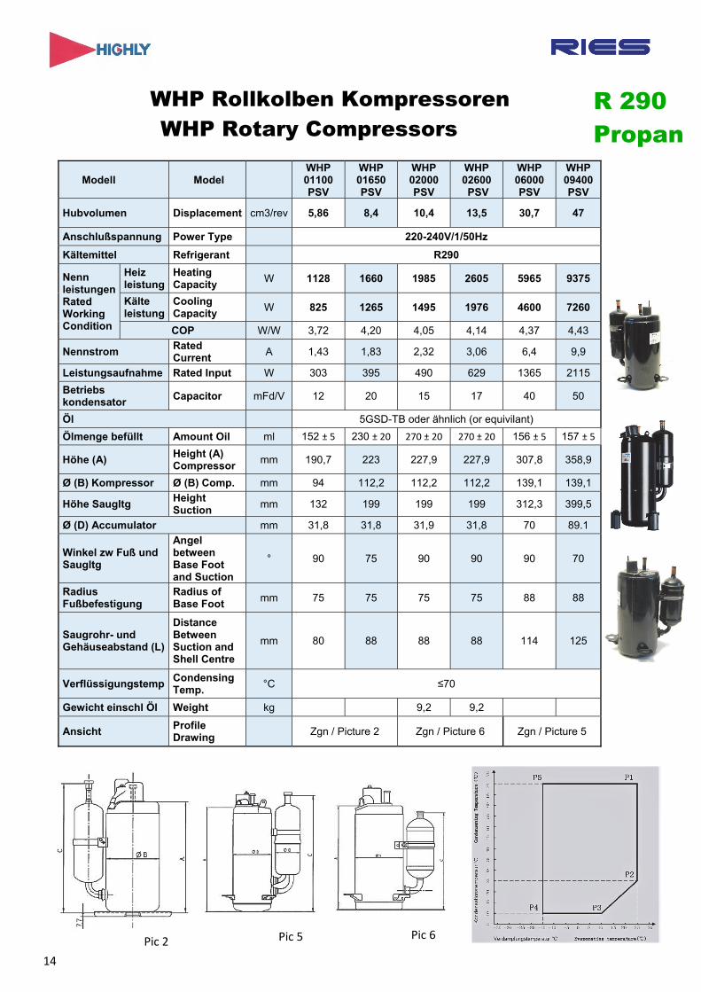
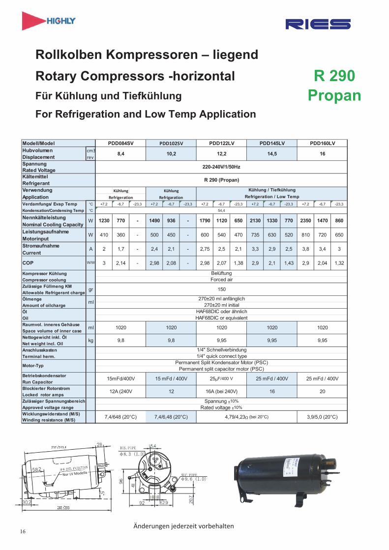
WHP Rollkolben Kompressoren WHP Rotary Compressors
Modell Model WHP 01100 PSV
WHP 01650 PSV
WHP 02000 PSV
WHP 02600 PSV
WHP 06000 PSV
WHP 09400 PSV
Hubvolumen Displacement cm3/rev 5,86 8,4 10,4 13,5 30,7 47
Anschlußspannung Power Type 220-240V/1/50Hz
Kältemittel Refrigerant R290
Nenn leistungen Rated Working Condition
Heiz leistung
Heating Capacity
W 1128 1660 1985 2605 5965 9375
Kälte leistung
Cooling Capacity
W 825 1265 1495 1976 4600 7260
COP W/W 3,72 4,20 4,05 4,14 4,37 4,43
Nennstrom Rated Current
A 1,43 1,83 2,32 3,06 6,4 9,9
Leistungsaufnahme Rated Input W 303 395 490 629 1365 2115
Betriebs kondensator
Capacitor mFd/V 12 20 15 17 40 50
Öl 5GSD-TB oder ähnlich (or equivilant)
Ölmenge befüllt Amount Oil ml 152 ± 5 230 ± 20 270 ± 20 270 ± 20 156 ± 5 157 ± 5
Höhe (A) Height (A) Compressor
mm 190,7 223 227,9 227,9 307,8 358,9
Ø (B) Kompressor Ø (B) Comp. mm 94 112,2 112,2 112,2 139,1 139,1
Höhe Saugltg Height Suction
mm 132 199 199 199 312,3 399,5
Ø (D) Accumulator mm 31,8 31,8 31,9 31,8 70 89.1
Winkel zw Fuß und Saugltg
Angel between Base Foot and Suction
° 90 75 90 90 90 70
Radius Fußbefestigung
Radius of Base Foot
mm 75 75 75 75 88 88
Saugrohr- und Gehäuseabstand (L)
Distance Between Suction and Shell Centre
mm 80 88 88 88 114 125
Verflüssigungstemp Condensing Temp.
°C ≤70
Gewicht einschl Öl Weight kg 9,2 9,2
Ansicht Profile Drawing
Zgn / Picture 2 Zgn / Picture 6 Zgn / Picture 5
R 290 Propan
Pic 2 Pic 5 Pic 6
14
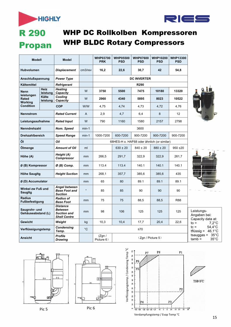
WHP DC Rollkolben Kompressoren WHP BLDC Rotary Compressors
Modell Model WHP03700
PRK WHP05500
PSD WHP07600
PSD WHP10200
PSD WHP13300
PSD
Hubvolumen Displacement cm3/rev 16,2 22,6 30,7 42 54,8
Anschlußspannung Power Type DC INVERTER
Kältemittel Refrigerant R290
Nenn leistungen Rated Working Condition
Heiz leistung
Heating Capacity
W 3750 5500 7475 10180 13320
Kälte leistung
Cooling Capacity
W 2960 4340 5895 8023 10522
COP W/W 4,75 4,74 4,73 4,72 4,76
Nennstrom Rated Current A 2,9 4,7 6,4 8 12
Leistungsaufnahme Rated Input W 790 1160 1580 2157 2798
Nenndrehzahl Nom. Speed min-1 3600
Drehzahlbereich Speed Range min-1 1000-7200 600-7200 900-7200 900-7200 900-7200
Öl Oil 68HES-H o. HAF68 oder ähnlich (or similar)
Ölmenge Amount of Oil ml 630 ± 20 840 ± 20 880 ± 20 950 ±20
Höhe (A) Height (A) Compressor
mm 266,5 291,7 322,9 322,9 261,7
Ø (B) Kompressor Ø (B) Comp. mm 113.4 113.4 140.1 140.1 140.1
Höhe Saugltg Height Suction mm 268,1 357,7 385,6 385,6 435
Ø (D) Accumulator mm 65 80 89.1 89.1 89.1
Winkel zw Fuß und Saugltg
Angel between Base Foot and Suction
° 85 85 90 90 90
Radius Fußbefestigung
Radius of Base Foot
mm 75 75 88,5 88,5 R88
Saugrohr- und Gehäuseabstand (L)
Distance Between Suction and Shell Centre
mm 98 106 125 125 125
Gewicht Weight kg 10,3 10,4 17,7 20,4 22,6
Verflüssigungstemp Condensing Temp.
°C ≤70
Ansicht Profile Drawing
(Zgn / Picture 6)
(Zgn / Picture 5)
Verflüssigungstemp / Conden
sing Te
mp °C
R 290 Propan
Verdampfungstemp / Evap Temp °C
Pic 5 Pic 6
Leistungs- Angaben bei: Capacity data at: to = 7,2°C tc = 54,4°C tflüssig = 46,1°C tsauggas = 35°C tamb = 35°C
15
16
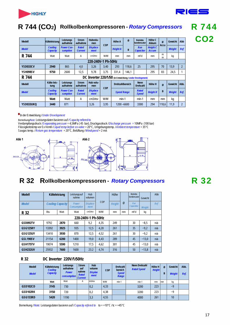
R 744 (CO2) Rollkolbenkompressoren - Rotary Compressors
In der Entwicklung / Under Development Bemerkung/Note: Leistungsdaten basieren auf / Capacity refered to Verdampfungsdruck / Evaporating pressure = 4,5MPa ( 45 bar), Druckgasdruck / Discharge pressure = 10MPa (100 bar) Flüssigkeitstemp vor Ex Ventil / Liquid temp before ex-valve = 20°C, Umgebungstemp. / Ambient temperature = 35°C Saugas temp. / Return gas temperature = 20°C, Belüftung / Windspeed = 2 m/s
Abb 1 Abb 2
R 32 Rollkolbenkompressoren - Rotary Compressors
Modell Kälteleistung Leistungs aufnahme
Strom aufnahme
Hubvolu- men
COP Höhe A Ø
B
Betriebs kondensator
Höhe C Akkum Ø
Accu Gewicht Abb
Model Cooling Capacity
Power Con- sumption
Rated Current
Displace ment Height A Run
Capacitor Height C Accum Weight Ref
R 744 Watt Watt A cm3/rev W/W mm mm mFd mm m m kg
220-240V-1 Ph-50Hz YSD033CV 2940 865 4,0
3 3,26 3,40 293 118,6 25 295 70 13,9 2
YSH098SV 9750 2600 12,5 9,78 3,75 331,4 146,1 295 83 24,5 1
R 744 DC Inverter 220/1/50 (in Entwicklung / under Development)
Modell Kälte leis- tung
Leistungs aufnahme
Strom aufnahme
Hub volu- men
COP Drehzahlbereich Nenn
Drehzahl Höhe H Ø
B
Gewicht Abb.
Model Cooling Capacity
Power Con- sumption
Rated Current
Displace ment Speed Range Rated
Speed Height H Weight Ref.
Watt Watt A cm3/rev W/W min-1 min-1 mm mm kg YSD033UKQ 3440 871 3,26 3,95 1200 –6600 3300 294 118,6 11,9 2
Modell Kälteleistung Leistungsauf nahme
Hub volumen
COP
Höhe
Ø
Betriebs kondensator Gewicht
Abb
Model Cooling Capacity Power Consumption
Displace ment
Height Run Capacititor Weight
Ref
R 32 Btu Watt Watt cm3/rev W/W mm mm mFd kg
220-240V-1 Ph-50Hz GSD092TV 9792 2870 660 9,2 4,35 249 30 ~8,5 n/a GSG125RY 13392 3925 935 12,5 4,20 261 35 ~9,2 n/a GSG125UY 13410 3930 870 12,5 4,52 261 30 ~9,2 n/a GSL190SV 21154 6200 1400 19,0 4,43 289 45 ~13,0 n/a GSH175TV 19074 5590 1210 17,5 4,62 301 45 ~13,0 n/a GSH232UV 25932 7600 1600 23.2 4,74 316 50 ~13,8 n/a
Modell
Model
Kälteleistung Cooling Capacity
Leistungs aufnahme
Power consumption
Strom auf
nahme Rated
Current
Hub volumn Displae
ment
COP Drehzahl bereich
Speed Range
Nenn Drehzahl Rated Speed
Höhe H Height
Ø
B
Gewicht
Weight
Abb.
Ref.
Watt Watt A cm3/rev W/W min-1 min-1 mm mm kg
GSD102CD 3145 730 10,2 4,33 3200 223 ~9
GSD102RK 3150 720 10,2 4,38 3200 223 ~9
GSG133RD 5420 1190 13,3 4,55 4000 261 10
Bemerkung / Note: Leistungsdaten basieren auf / Capacity refered to to = +10°C / tc = +45°C
R 32 DC Inverter 220V/1/50Hz
R 744 CO2
R 32
17
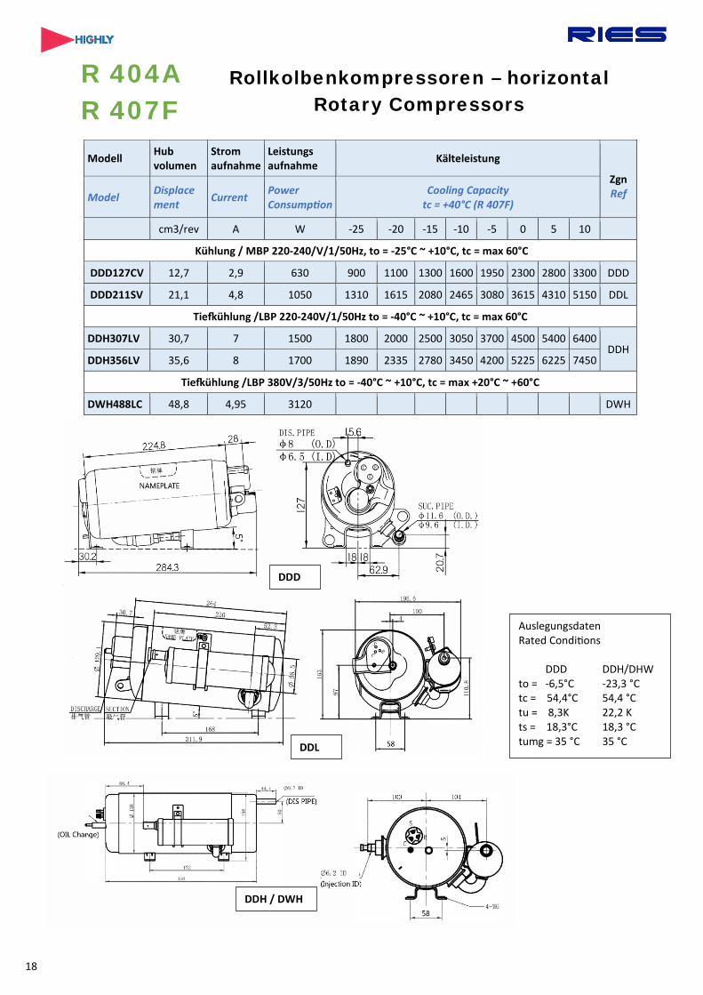
Modell Hub volumen
Strom aufnahme
Leistungs aufnahme Kälteleistung
Zgn Ref Model Displace
ment Current Power Consumption
Cooling Capacity tc = +40°C (R 407F)
cm3/rev A W -25 -20 -15 -10 -5 0 5 10
Kühlung / MBP 220-240/V/1/50Hz, to = -25°C ~ +10°C, tc = max 60°C
DDD127CV 12,7 2,9 630 900 1100 1300 1600 1950 2300 2800 3300 DDD
DDD211SV 21,1 4,8 1050 1310 1615 2080 2465 3080 3615 4310 5150 DDL
Tie�ühlung /LBP 220-240V/1/50Hz to = -40°C ~ +10°C, tc = max 60°C
DDH307LV 30,7 7 1500 1800 2000 2500 3050 3700 4500 5400 6400 DDH
DDH356LV 35,6 8 1700 1890 2335 2780 3450 4200 5225 6225 7450
Tie�ühlung /LBP 380V/3/50Hz to = -40°C ~ +10°C, tc = max +20°C ~ +60°C
DWH488LC 48,8 4,95 3120 DWH
R 404A R 407F
Rollkolbenkompressoren – horizontal Rotary Compressors
Auslegungsdaten Rated Condi�ons
DDD DDH/DHW to = -6,5°C -23,3 °C tc = 54,4°C 54,4 °C tu = 8,3K 22,2 K ts = 18,3°C 18,3 °C tumg = 35 °C 35 °C
DDD
DDL
DDH / DWH
18

MINI ‐Rollkolben Kompressoren MINI Rotary Compressors
Klein ‐ leise ‐ hocheffizient Compact – Quiet - High efficient
Kälteleistungen BSW020SK
Drehzahl Speed min-1 2700 3600 4500 5400
tc/to °C 0 5 10 0 5 10 15 -5 0 5 -5 0 35 W 165 212 259 245 312 379 447 40 W 155 201 249 232 300 367 435 45 W 137 184 231 200 270 335 405 216 281 345 50 W 190 250 310 370 192 256 320 213 275 60 W 137 200 260 323 207 267
Modell Model BSW014KE BSW020SK
Kältemittel Refrigerant R134a / R 1234yf Leistungsbereich Capacity range 100 – 700 W Frequenz Bereich Frequency range 2400-6000Verdampfungstemp. Bereich Evaporating temp. range 25 - +24°CKondensationstemp. Bereich Condensing temp. range 26-76°CHubvolumen Displacement 1,4 2,0 Nenn-Kälteleistung Rated Capacity 235W 346W Nennleistungsaufnahme Rated motor input 96 141 Nennstrom Rated current 3,65 5,06 Nenn Drehzahl Rated speed 4500 Öl Oil POEAbmessungen Outline drawing Zeichnung (Picture) 1 Gewicht Weight 980 gSpannung Power Inverter Eingang (Input) 48Vdc Inverter Drive controller Auslegbar / Configurable
Tragbarer Kühlschrank Portable refrigerator
Medizinische Mobile Kühlung Medical mobile refrigeration
CPU/GPU‐Kühlung CPU/GPU refrigeration
Klimatisierung für Basisstationen von Mobilfunknetzen Communication base station equipment refrigerator
122
59, 42,
ID Ø
ID Ø
85,
79,
88,
106,5
Änderung jederzeit vorbehalten. We reserve the right to modify at any time without prior notice
19
R 134a R 600
R 1234yf

Zubehör / Accessoires
Modell Nenn
spannung Power
Heiz leistung Heating
Passend für Suitable for
Durchmesser Diameter Umfang Girth Bauform
Shape
Thermostatische Regelung
Thermostatic Control Volt Watt Min Max Min Max
CH025 240V 25 Die meisten Rollkolben Verdichter
90mm 150mm 280mm 470mm Rund
Nein/no
CH025-TH 240V 25 Most Rotary
Compressors 90mm 150mm 280mm 470mm Ja/yes
Anschluss Kompressor - Betriebskondensator Wiring Diagram Compressor – Run Capacitor
Bestell Order No
mFd/ Volt
CBB60
1A.287 4,0 / 400/450 1A.213 5,0 / 380/450 1A.600 6,0 / 380/450 1A.267 6,5 / 380/450 1A.209 8,0 / 400/450 1A.215 10,0 / 400/450 1A.150 15,0 / 400/450 1A.359 17,0 / 400/450 1A.088 20,0 / 400/450 1A.089 25,0 / 400/450 1A.090 30,0 / 400/450 1A.091 35,0 / 400/450 1A.092 40,0 / 400/450 1A.093 45,0 / 400/450 1A.201 50,0 / 400/450 1A.211 55,0 / 400/450 1A.219 60,0 / 400/450
Drehzahlregelung / Inverter
Die Auswahl eines passenden Inverters setzt vielzählige Test mit dem Verdichter und dem Inverter voraus um die korrekten Einstellungen für den Verdichter zu ermitteln und festzulegen. Die minimalen und maximalen Drehzahlen eines Verdichters sind wesentlichen durch die maximale Stromaufnahme und den in den Tests ermittelten möglichen Frequenzbereich festgelegt. Unsere Inverter der Baureihe E1045/1145 regeln die Drehzahl herunter wenn die maximale Drehzahl oder Stromaufnahme erreicht ist. Je nach Verwendung eines Verdichters in Kühl-Klima– oder Wärmepumpenbereich ist die Verwendung unterschiedliche Inver- tergrößen erforderlich. Die Einstellung unserer Inverter auf die einzelnen Verdichter erfolgt mittels DIP-Schalteru n d o d e r p e r M o d b u s an dem Inverter. Sehen Sie hierzu auch Seite 20 mit weiteren Informationen über passende Inverter.
Vorteile
GenaueTemperaturregelung:Unwesentliche Temperaturveränderungen aufgrund der Drehzahländerung durch automatisch Anpassung an den Leistungsbedarf.
Hohe Effizienz: Leistet nur was benötigt wird um Kühlung oder Heizungsbedingungen einzuhalten und spart dadurch sowohl Energie wie auch Geld.
Klima: Angenehmeres Klima mit der gewünschten Temperatur und Luftfeuchtigkeit Kompaktere Größe und geringeres Gewicht:
Aufgrund der veränderbaren Dreh- zahl kann der Inverter-Verdichter im Vergleich zur einem mit fester Drehzahl kleiner gewählt werden.
Es besitzt daher um ca. 30% kompakter Abmessungen und geringes Gewicht. Er reduziert damit den Platzbedarf und Investitionskosten
Speed control / Inverter
A selection of a suitable inverter needs numerous test with compressor and inverter to determine and define correct settings for the compressor. The minimum and maximum speed of a compressor is determined by the maximum current and the frequency range of the inverter and compressor. In our Inverter range E1045/1145 the inverter will reduce the speed of the compressor when the maximum current and temperature is reached. Depending of the application of a compressor in refrigeration, air conditioning or heat pump range it is possible to choose different inverter sizes for a compressor but also for different ones. The selection of a compressor and functions is made via DIP-switches and/or Modbus.. See page 20 for further informations about available inverter
Advantages Precise Temperature control: Insignificant temperature changes due to the change in speed by automatically adapting to the power requirements.
High Efficiency: Does just what is needed to comply with cooling or heating conditi- ons, thereby saving both energy as well as money.
Air conditioning : More pleasant air condition at the desired temperature and humidity Compact size and lighter weight: Due to the variable speed of the inverter compressor compared to a fixed speed one a smaller compressor can be chosen. It therefore has more compact dimensions (~30%) and lower weight. Thus it reduces the space requirement and investment cost
Bandheizung mit/ ohne thermostatische Regelung Band heater with/without thermostatic Control
20

Speedline
RIES GmbH, Rudolf‐Diesel‐Str. 10, 64569 Nauheim, GERMANY, Fon +49 6152 9741 0, Fax +49 6152 9741 21, Email: info@ries‐gmbh.de, www ries‐gmbh.de
Beschreibung
Der Speed Controller E1045 ist ein kom-binierter Frequenzumrichter zur Steue-rung von EC, PMSM, BLDC und Standard Asynchronmotoren in drei Leistungsgrö-ßen 1500W (5,5A), 2000W (6,5A) und 5500W (16A) für 3-Phasen-Motoren mit einphasiger bzw. dreiphasiger Stromver-sorgung. Die hier vorgestellte Version E1045/E1002 ist für diverse HITACHI HIGHLY Rotary Kompressoren ausgelegt und programmiert. Weitere nicht aufge-führte Modelle / Fabrikate sind in Vorbe-reitung bzw. können auf Wunsch ergänzt werden. Sprechen Sie uns an bzw. ent-nehmen Sie weitere Einzelheiten und/oder Modelle / Motoren und Kom-pressorenhersteller unserer Homepage www.ries-gmbh.de
Gehäuse / Platine / Sicherheit Der Speed Controller E1045DP wird in einem robusten Metallgehäuse (IP54) für anspruchsvolle Umgebungen geliefert. Die kompakte Bauweise bietet viele Be-festigungsmöglichkeiten auch zusammen mit anderen Motoren. Da das Gehäuse nicht über eine aktive Kühlung verfügt, ist der Geräuschpegel sehr gering und eine Wartung nicht erforderlich. Der Inverter ist auch ohne Gehäuse als Modell E1045R (IP00) lieferbar.
Description
Metalbox / PCB / Security SpeedController E1045DP is supplied in a solid (IP54) metal housing for de-manding environments. The compact construction offers many mounting op-tions also together with or on other mo-tors. The construction does not feature active cooling. Therefore the sound level is very low and no maintenance is required. The Inverter is also available without box as PCB-Model E1045R
(IP00)
Wichtige Merkmale:
Regelung von EC, PMSM, BLDC und Standard-Asynchron-Motoren für bis 1500W (5,5A), 2000W (6,5A) und 5500 Watt
Inverter Anschluss in 230V/1/50Hz und 400/3/50
DP-Ausführung Robuste IP 54 Konstruktion im Metallgehäuse. Farbe: hellgrau
R-Ausführung Platine mit Wärmeleitblech zum Einbau in Geräte oder Schaltschrank: IP00
Leise und wartungsfrei
Benutzerfreundlich: Schneller Anschluss und einfache Montage
Weitere Modelle und Motor/ Verdichterfabrikate auf An-frage
HIGHLIGHTS:
Adjustment of EC, PMSM, BLDC and standard asyn-chronous motors up to 1500W (3 x 5,5A), 2000W (3 x 6,5A) and 5500W (3 x 16A)
Inverter power supply: 230V/1/50Hz for higher capacities up to 5500 W model E1002 for 400V/3/50Hz
DP Version -
Solid IP 54 construction in metal housing. IP54
R-Version PCB with heat sink for installation in units and cabinets. IP00
Both versions are imple-
mented with firmware for various HITACHI HIGHLY Rotary compressors to be choosen by a DIP-Switch. Further models on request
Silent and maintenance free
User friendly Quick and easy mounting
Inverter Drehzahlregler E1045 / E20 für Rotary Kompressoren Inverter SPEED CONTROLLER E1045 / E20 for Rotary Compressors
E1045R
Modell Inverter Motor/Komp
E1045-1500 230V 1500 W 10A 3 x 5,5A
E1045-2000 230 V 2000 W 16A 3 x 6,5A
E20-75-356 400 V 7500 W 16A 3 x 16A
Max. Belastung Inverter Max Usage of Converter
E20-75-356
E1045DP
SpeedController E 1045 is a combined frequency converter for control of EC, PMSM, BLDC and standard asynchro-nous motors in three sizes 1500W (5,5A), 2000W (6,5A), 5500W (16A) for 3 phase motors with single and three phase supply. The versions shown her-e E1045/1002 are programmed for va-rious HITACHI HIGHLY Rotary com-pressors. Other not listed mo-dels/motors/brands are in preparation or can be added on request. Please contact us or refer for further informati-on and models to our website www.ries-gmbh.de
21
*
*
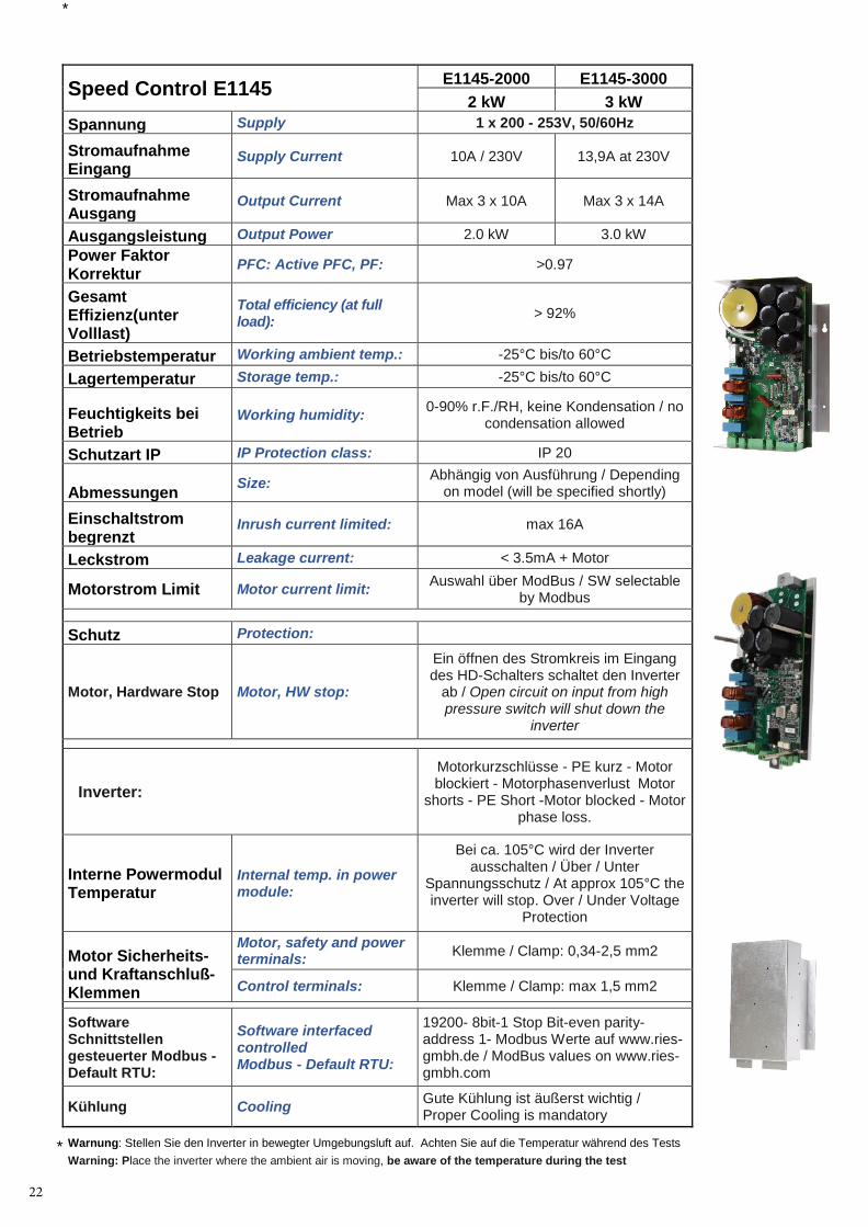
Speed Control E1145 E1145-2000 E1145-3000 2 kW 3 kW
Spannung Supply 1 x 200 - 253V, 50/60Hz
Stromaufnahme Eingang
Supply Current 10A / 230V 13,9A at 230V
Stromaufnahme Ausgang
Output Current Max 3 x 10A Max 3 x 14A
Ausgangsleistung Output Power 2.0 kW 3.0 kW Power Faktor Korrektur PFC: Active PFC, PF: >0.97
Gesamt Effizienz(unter Volllast)
Total efficiency (at full load): > 92%
Betriebstemperatur Working ambient temp.: -25°C bis/to 60°C
Lagertemperatur Storage temp.: -25°C bis/to 60°C
Feuchtigkeits bei Betrieb
Working humidity: 0-90% r.F./RH, keine Kondensation / no condensation allowed
Schutzart IP IP Protection class: IP 20
Abmessungen Size: Abhängig von Ausführung / Depending on model (will be specified shortly)
Einschaltstrom begrenzt
Inrush current limited: max 16A
Leckstrom Leakage current: < 3.5mA + Motor
Motorstrom Limit Motor current limit: Auswahl über ModBus / SW selectable by Modbus
Schutz Protection:
Motor, Hardware Stop Motor, HW stop:
Ein öffnen des Stromkreis im Eingang des HD-Schalters schaltet den Inverter
ab / Open circuit on input from high pressure switch will shut down the
inverter
Inverter: Motorkurzschlüsse - PE kurz - Motor blockiert - Motorphasenverlust Motor
shorts - PE Short -Motor blocked - Motor phase loss.
Interne Powermodul Temperatur
Internal temp. in power module:
Bei ca. 105°C wird der Inverter ausschalten / Über / Unter
Spannungsschutz / At approx 105°C the inverter will stop. Over / Under Voltage
Protection
Motor Sicherheits- und Kraftanschluß-Klemmen
Motor, safety and power terminals: Klemme / Clamp: 0,34-2,5 mm2
Control terminals: Klemme / Clamp: max 1,5 mm2
Software Schnittstellen gesteuerter Modbus - Default RTU:
Software interfaced controlled Modbus - Default RTU:
19200- 8bit-1 Stop Bit-even parity-address 1- Modbus Werte auf www.ries-gmbh.de / ModBus values on www.ries-gmbh.com
Kühlung Cooling Gute Kühlung ist äußerst wichtig / Proper Cooling is mandatory
Warnung: Stellen Sie den Inverter in bewegter Umgebungsluft auf. Achten Sie auf die Temperatur während des Tests Warning: Place the inverter where the ambient air is moving, be aware of the temperature during the test
22
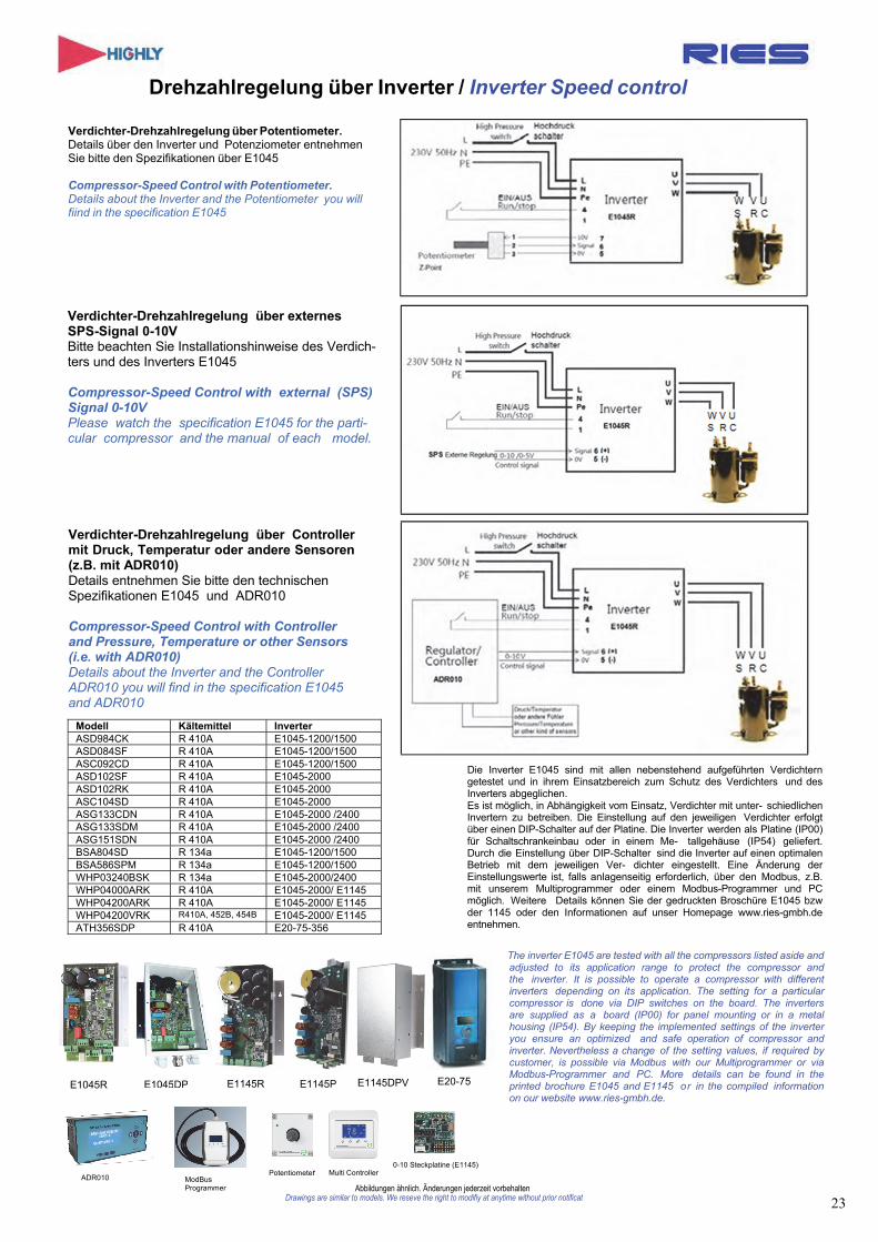
Drehzahlregelung über Inverter / Inverter Speed control
Verdichter-Drehzahlregelung über Potentiometer. Details über den Inverter und Potenziometer entnehmen Sie bitte den Spezifikationen über E1045
Compressor-Speed Control with Potentiometer. Details about the Inverter and the Potentiometer you will fiind in the specification E1045
Verdichter-Drehzahlregelung über externes SPS-Signal 0-10V Bitte beachten Sie Installationshinweise des Verdich- ters und des Inverters E1045
Compressor-Speed Control with external (SPS) Signal 0-10V Please watch the specification E1045 for the parti- cular compressor and the manual of each model.
Verdichter-Drehzahlregelung über Controller mit Druck, Temperatur oder andere Sensoren (z.B. mit ADR010) Details entnehmen Sie bitte den technischen Spezifikationen E1045 und ADR010
Compressor-Speed Control with Controller and Pressure, Temperature or other Sensors (i.e. with ADR010) Details about the Inverter and the Controller ADR010 you will find in the specification E1045 and ADR010
Die Inverter E1045 sind mit allen nebenstehend aufgeführten Verdichtern getestet und in ihrem Einsatzbereich zum Schutz des Verdichters und des Inverters abgeglichen. Es ist möglich, in Abhängigkeit vom Einsatz, Verdichter mit unter- schiedlichen Invertern zu betreiben. Die Einstellung auf den jeweiligen Verdichter erfolgt über einen DIP-Schalter auf der Platine. Die Inverter werden als Platine (IP00) für Schaltschrankeinbau oder in einem Me- tallgehäuse (IP54) geliefert. Durch die Einstellung über DIP-Schalter sind die Inverter auf einen optimalen Betrieb mit dem jeweiligen Ver- dichter eingestellt. Eine Änderung der Einstellungswerte ist, falls anlagenseitig erforderlich, über den Modbus, z.B. mit unserem Multiprogrammer oder einem Modbus-Programmer und PC möglich. Weitere Details können Sie der gedruckten Broschüre E1045 bzw der 1145 oder den Informationen auf unser Homepage www.ries-gmbh.de entnehmen.
The inverter E1045 are tested with all the compressors listed aside and adjusted to its application range to protect the compressor and the inverter. It is possible to operate a compressor with different inverters depending on its application. The setting for a particular compressor is done via DIP switches on the board. The inverters are supplied as a board (IP00) for panel mounting or in a metal housing (IP54). By keeping the implemented settings of the inverter you ensure an optimized and safe operation of compressor and inverter. Nevertheless a change of the setting values, if required by customer, is possible via Modbus with our Multiprogrammer or via Modbus-Programmer and PC. More details can be found in the printed brochure E1045 and E1145 or in the compiled information on our website www.ries-gmbh.de.
Abbildungen ähnlich. Änderungen jederzeit vorbehaltenDrawings are similar to models. We reseve the right to modifiy at anytime without prior notificat
Modell Kältemittel Inverter ASD984CK R 410A E1045-1200/1500 ASD084SF R 410A E1045-1200/1500 ASC092CD R 410A E1045-1200/1500 ASD102SF R 410A E1045-2000 ASD102RK R 410A E1045-2000 ASC104SD R 410A E1045-2000 ASG133CDN R 410A E1045-2000 /2400 ASG133SDM R 410A E1045-2000 /2400 ASG151SDN R 410A E1045-2000 /2400 BSA804SD R 134a E1045-1200/1500 BSA586SPM R 134a E1045-1200/1500 WHP03240BSK R 134a E1045-2000/2400 WHP04000ARK R 410A E1045-2000/ E1145WHP04200ARK R 410A E1045-2000/ E1145WHP04200VRK R410A, 452B, 454B E1045-2000/ E1145ATH356SDP R 410A E20-75-356
E1045R E1045DP E1145R E1145DPV E1145P E20-75
ADR010 ModBus Programmer
Potentiometer Multi Controller0-10 Steckplatine (E1145)
23
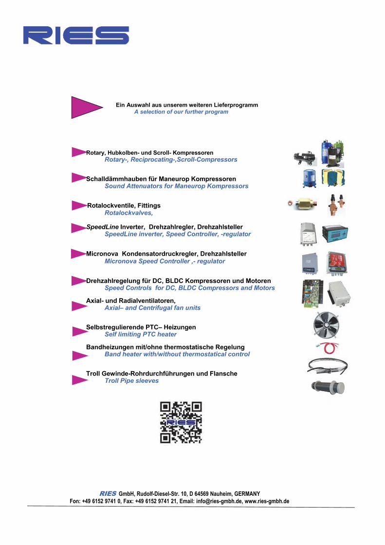
Ein Auswahl aus unserem weiteren Lieferprogramm A selection of our further program
Rotary, Hubkolben- und Scroll- Kompressoren Rotary-, Reciprocating-,Scroll-Compressors
Schalldämmhauben für Maneurop Kompressoren Sound Attenuators for Maneurop Kompressors
Rotalockventile, Fittings Rotalockvalves,
SpeedLine Inverter, Drehzahlregler, Drehzahlsteller SpeedLine inverter, Speed Controller, -regulator
Micronova Kondensatordruckregler, Drehzahlsteller Micronova Speed Controller ,- regulator
Drehzahlregelung für DC, BLDC Kompressoren und Motoren Speed Controls for DC, BLDC Compressors and Motors
Axial- und Radialventilatoren, Axial– and Centrifugal fan units
Selbstregulierende PTC– Heizungen Self limiting PTC heater
Bandheizungen mit/ohne thermostatische Regelung Band heater with/without thermostatical control
Troll Gewinde-Rohrdurchführungen und Flansche Troll Pipe sleeves
RIES GmbH, Rudolf-Diesel-Str. 10, D 64569 Nauheim, GERMANY Fon: +49 6152 9741 0, Fax: +49 6152 9741 21, Email: [email protected], www.ries-gmbh.de


![Fax: E-Mail: Web: BeziFix Anker BS/BSS info@sihga.com Web: TAKE THE BEST BeziFix® Anker BS/BSS Technische Daten Abmessung [mm] BeziFix® Anker BS d 1 DS SW C 10 - 15 60 Abmessung](https://img.dokumen.tips/doc/110x75/5ac931ef7f8b9acb688d30ec/fax-e-mail-web-bezifix-anker-bsbss-infosihgacom-web-take-the-best-bezifix.jpg)


