Embed Size (px)
Citation preview
ROLLED PRODUCTS
ROLLING F L A T STEEL ON THE 250 L I G H T - S E C T I O N MILL
A. A. K u g u s h i n , A. I. P r o k o p ' e v ,
V. N. A s a n o v , a n d V. S. T s e I u i k o v
The 250-2 continuous l ight-section mi l l of the West Siberian metallurgical plant consists of 23 working stands: seven horizontal stands in the roughing group, four horizontal stands in the intermediate miU group, and six a l ternat-
ing vertical and horizontal stands in the two finishing mi l l groups. The roils in the working stands are equipped with
individual controlled dc electric motors working through reducing gear trains and pinion stands. The one exception
is the XIV stand, which lacks a reducing gear train.
i, \ / " , b
I-- cl. I-- 5'
C1. ]Nr
F 56---~ ,,~, I cl.zr
~I I I--- 51,6 - r "---~
49
~ ' ---~ f5 ~ -
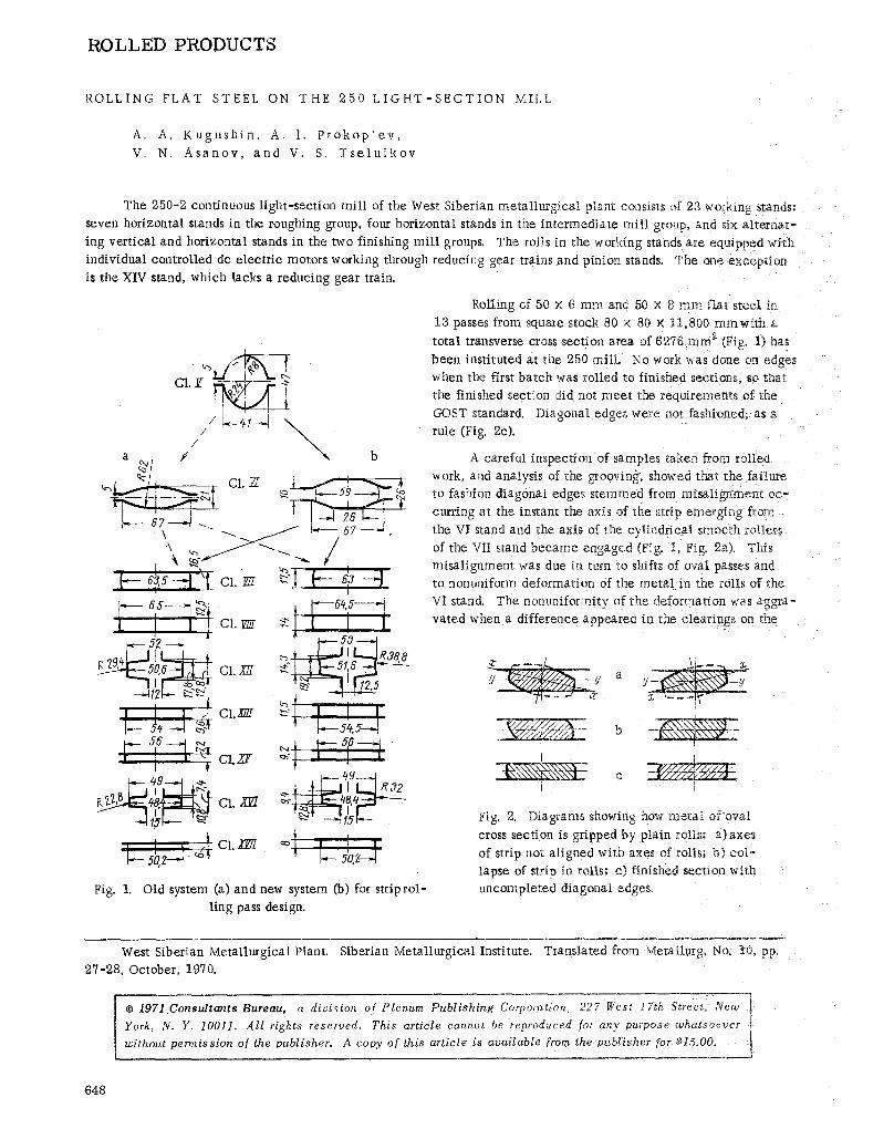
L;A Fig. 1. Old system (a) and new system (b) for striprol-
ling pass design.
Rolling of 50 x 6 mm and 50 x 8 mm Qat stee~ in
13 passes from square stock 80 x 80 x t1,800 mmwfth a
total transverse cross section area of 6276 mm ~ (Fig. 1) has
been instituted at the 250 m i l l No work was done on edges when the first batch was rolled to finished sections, so that
the finished section did not meet the requirements of the
GOST standard. Diagonal edges were not fashioned, as a rule (Fig. 2c).
A careful inspection of samples taken from rolled work, and analysis of the grooving, showed t~hat the failure to fashion diagonal edges stemmed from misal ignment oc-
curring at the instant the axis of the strip emerging from
the VI stand and the axis of the cylindrical smooth rollers
of the VII stand became engaged (Fig. 1, Fig. 2a). This misal ignment was due in turn to shifts of oval passes and
to nonuniform deformation of the metal in the roils of the VI stand. The nonuniformity of the deformation, was aggra- vated when a difference appeared in the clearings on the
Y
Fig. 2. Diagrams showing how metal of oval
cross section is gripped by plain rolls: a)axes
of strip not aligned with axes of roils; b) col- lapse of strip in rolls; c) finished section with uncompleted diagonal edges~
West Siberian Metallurgical Plant. Siberian Metallurgical Institute. Translated from Metallurg, No. I0, pp.
27-28, October, 1970.
�9 1971Consultants Bureau, a division of Plenum Publishing Corporation, 227 West 17th .Street, New 1
York, N. Y. 10011. All rights reserved. This article cannot be reproduced for any purpose whatsoever t I without permission of the publisher. A copy of this article is available from the publisher for $15.00.
___J
648
roll collars re la t ive to the ver t ica l axis of the pass, or whenever the mi l l guide fittings were not properly adjusted,,
etc. Al l these factors were responsible for distortion of the configuration of the work cross section after roiling in
the rolls of the VII stand (Fig. 2b) and the failure to achieve the proper geometry in the finished section.
Subsequent area reduction steps in the plain rolls of the horizontal stands in the in termedia te and finishing mi l l groups fai led to correct the geometry of the strip emerging from the VII stand. Rolling in the ver t icaI stands XII and XVI with strip reduction in width in the edging passes l ikewise fai led to even out the edges because of the difference in the diagonals of the strip. The large.diagonal was worked as a consequence of the fact that the corners were sufficiently f i l led up with meta l , whereas the smal ler diagonal was not worked because the corresponding co t - nets were not sufficiently f i l led up. Increasing the draft in the edging passes fai led to yield the desired results, since the strip bent in that case. This brought about even more severe deviat ions from the rectangular contouring spec i - fled for the edges.
Production of a section with sharp rectangular edges is one of the requirements imposed by the GOST standard for finished strip. This can be achieved only when strip with a minimum difference in diagonals is deformed in edg- ing passes with uniformly distributed total area reduction.
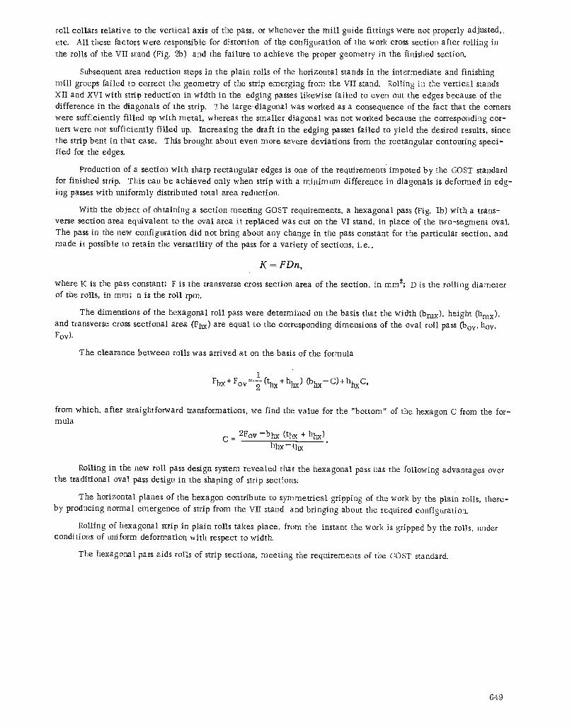
With the object of obtaining a sect ion meet ing GOST requirements, a hexagonal pass (Fig. lb) with a trans- verse section area equivalent to the oval area i t replaced was cut on the VI stand, in place of the two-segment oval.
The pass in the new configuration did not bring about any change in the pass constant for the part icular section, and made it possible to retain the versat i l i ty of the pass for a var ie ty of sections, i .e . ,
K = F D n ,
where K is the pass constant; F is the transverse cross section area of the section, in ram2; D is the roi l ing diameter of the rolls, in ram; n is the roll rpm.
The dimensions of the hexagonal roll pass were determined on the basis that the width (bmx), height (hmx), and transverse cross sect ional area (Fhx) are equal to the corresponding dimensions of the oval roll pass (boy, hov, Fov).
The c learance between rolls was arr ived at on the basis of the formula
1 Fhx + Fov =-~- (thx + hhx) (bhx- C) + hhx C,
from which, after straightforward transformations, we find the value for the "bottom" of the hexagon C from the for- m ula
C = 2Fov - b h x (tbx + hhx) hhx - t h x "
Rolling in the new roll pass design system revealed that the hexagonal pass has the following advantages over the t radi t ional oval pass design in the shaping of strip sections;
The horizontal planes of the hexagon contribute to symmetr ica l gripping of the work by the plain roils, there- by producing normal emergence of strip from the VII stand and bringing about the required configuration.
Rolling of hexagonal strip in plain rolls takes place, from the instant the work is gripped by the rolls, under conditions of uniform deformation with respect to width,
The hexagonal pass aids rolls of strip sections, meet ing the requirements of the CA)ST standard.
649