Embed Size (px)
Citation preview
1
Rolling Contact Fatigue Performance Contrasting Surface Densified, Powder Forged, and
Wrought Materials
William Jandeska GM Powertrain
Pontiac, MI 48340
Richard Slattery Capstan Atlantic
Wrentham, MA 02093
Francis Hanejko, Arthur Rawlings, Patrick King Hoeganaes Corporation
Cinnaminson, NJ 08077
Presented at PM2Tec 2005 Montreal, Canada June 19 - 23
Abstract: Previous experimental work demonstrated that rolling contact fatigue durability of high-density powder metallurgy samples was influenced by depth of surface densification (achieved via roll densification), sintering temperature, and heat treat practice. One observation of the previous work was reduced rolling contact fatigue life at high Hertz stress levels relative to wrought machined steel samples. There were also some questions regards the influence of nickel rich regions and how they affected rolling contact fatigue performance. In an effort to understand the influence of elemental nickel additions, FLN2-4405 samples were sintered at 2050 °F (1120 °C) and 2300 °F (1260 °C) and subsequently powder forged to full density. This experimental work was designed to clarify the effects of elemental nickel additions on rolling contact fatigue durability. Additionally, wrought AISI 8620 carburizing steel was machined into rolling contact fatigue samples, carburized and tested. Additionally, the AISI 8620 was evaluated for tensile, impact and fatigue characteristics in the quench and tempered condition. Introduction: Automotive powertrain requirements necessitate that individual components have mechanical properties adequate to insure system reliability up to 250,000 kilometers. [1] Multiple requirements of high static strength, bending fatigue, and rolling contact fatigue durability led gear designers to utilize forged and machined wrought steels to ensure long-term vehicle reliability. Although P/M offers lower component cost, fatigue limitations of conventional press and sintered components precluded P/M utilization in these demanding applications. Considerable research work is underway to explore the possibility of using high density P/M in applications traditionally fulfilled by wrought steels. [2,3,4,5] Specifically, advanced processing utilizing high core densities combined with selective surface densification may produce

2
components with nearly equivalent surface fatigue durability and core strengths suitable for these high strength applications. Prior experimental work demonstrated rolling contact fatigue life of P/M is dependent upon amount of surface porosity, depth of densification, and microstructural features such as type of martensite formed and secondary phases such as nickel rich areas. [2] Selectively densified P/M materials are strongly affected by the rolling contact fatigue stress level. Specifically, at Hertzian stresses at and below 1900 MPa, selectively densified P/M material exhibit rolling contact fatigue life equivalent to wrought steels. However, at Hertzian stresses approaching 2500 MPa, surface densified P/M materials had lower rolling contact fatigue life compared to wrought steels. In an effort to answer questions concerning influence of surface porosity, depth of carburized layer and effects of nickel rich regions prompted this investigation of full density P/M materials to potentially clarify these issues. As noted earlier, surface densified P/M materials showed equivalent rolling contact fatigue life to wrought steels at contact stresses of 1900 MPa and below. However, increasing demand for higher engine performance and smaller gears sizes place even greater performance demands on gear materials. To understand Hertzian stresses within gears, it useful to go through a typical contact stress calculation of a gear. Assume a gear with a 20° pressure angle and a Modulus of Elasticity of 30 million psi (206,000 MPa); the maximum compressive stress can be calculated according the following equation:
+=
G
Gtc
mm
FdWs 15715 {1} [Reference 6]
In which
! Sc = surface compressive stress in psi ! Wt = driving pressure in pounds = pinion torque/pitch radius ! F = face width in inches ! d = pitch diameter in inches ! mG = ratio of gear teeth to pinion teeth ! Ss = Maximum subsurface shear stress in psi
In addition to surface compressive stresses, there exists a maximum shear stress, which is calculated to be Ss = 0.295 Sc {2} [reference 6]. This maximum compressive shear stress occurs at a depth below the surface equal to approximately 0.40 times the bandwidth of contact. As an example, assume that an engine develops 250 ft-lbs of torque and this torque is transmitted through the pinions (load sharing between two pinions) with a pitch diameter of 1.500 inches, a face width of 1.000 inch and a final reduction ratio of 3.3 to 1, then the calculated stresses from equation {1} and equation {2} are as follows: ! Maximum Hertzian stress, Sc ~180,000 psi (1240 MPa) ! Maximum Sub surface shear stress, Ss ~55,000 psi (380 MPa) ! Depth of maximum shear ~0.009 inches (0.23 mm)

3
However, torque spikes because of adverse driving conditions or higher �mG� values associated with lower gear ratios, these maximum Hertzian and shear stresses can increase to greater than 150% of the values listed. Along with greater surface contact stress, the depth of maximum shear would increase approximately 40%. Thus for P/M to successfully replace wrought steel in these high strength applications, P/M processing must meet or even exceed the performance of current gear materials. Experimental Procedure: Sample Preparation: To understand the effects of nickel rich regions on rolling contact fatigue of P/M materials, an FLN2-4405 premix was prepared and samples were compacted to a nominal 6.8 g/cm³ density (preform dimensions 3.5 inch OD x 1.25 inch tall). Half of these samples were sintered at 2050 °F (1120 °C) and half were sintered at 2300 °F (1260 °C). After sintering, all samples were powder forged to ~100% pore free density (forged dimensions 4.0 inch OD x 1.0 inch tall) using a forging temperature of 1800 °F (980 °C). After forging, rolling contact fatigue samples were machined avoiding any powder-forged surface. Once machined, samples were vacuum carburized at 1700 °F (925 °C) for 3 hours, utilizing a 90 minutes boost cycle and a 90-minute diffuse cycle. Quenching was done with high-pressure nitrogen gas. All samples were then tempered at 400 °F (205°) for 1 hour. Carburizing was targeted to produce a 0.9 to 1.0% surface carbon after the boost phase. After carburizing, grinding of the ID was done to achieve the desired outer diameter to inner diameter concentricity. In order to understand the effects of carburizing practice on rolling contact fatigue life, forging quality AISI 8620 wrought steel was machined into rolling contact fatigue samples. These wrought samples were carburized at the same time as the FLN2-4405 samples. Additionally, the AISI 8620 material was machined into tensile, impact and rotating bending fatigue samples. These test specimens were tested according to MPIF standards. Rolling Contact Fatigue Testing As described in previous reports, rolling contact fatigue testing was performed using a ZF-RCF test bench. [2,7] Benefits of this screening method are as follows: ! Ability to test heat treated surface of component ! Line contact for applied Hertz stresses ! Full elasto-hydrodynamic lubrication thus focusing on material properties without
interference from surface pitting phenomena. ! Ability to incorporate sliding into test regime ! Relatively short test times to accelerate evaluation.
Test conditions for the ZF rolling contact fatigue test bench were as follows: ! Test speed of 3000 RPM, 9000 load cycles per minute ! Two load levels: 1900 / 2000 MPa and 2500 MPa, assuming a Young�s Modulus of 30
million psi (206,000 MPa), loading constant. ! Sliding of �24% between the test sample and load wheels. ! Lubricant: Dextron III, automatic gear box oil provided by General Motors Corporation,
the oil was held at 80 °C ± 2 °C.

4
! Failure during the rolling contact fatigue test was detected using an accelerometer, which detected excessive vibration from the surface spalling of the sample
! Five samples were evaluated at each Hertzian stress level. The probability of survival was calculated according to the following
o Ps = ((3m-1)/(3n+1)) * 100% {3} Results: Rolling Contact Fatigue Testing Rolling contact fatigue test results of powder forged FLN2-4405 and AISI 8620 are presented in Table 1. Test results are shown for Hertzian stress level, B50 life to failure, a ratio of B10 to B90 lives, plus the slope of the S-N curve. These properties are defined as follows: ! B50 50% statistical survival life, based on equation 3 ! B10 10% statistical survival life, based on equation 3 ! B90 90% statistical survival life, based on equation 3 ! Slope of S-N Curve Calculated slope of low cycle fatigue portion of S-N curve
Table 1 Rolling Contact Fatigue Live of Samples Evaluated
Material / Sinter Condition
Hertz Stress Level, MPa
B50 life, x 106 cycles
Ratio of B10 / B90 lives
Slope of S-N Curve
1900 13.0 1 : 1.9 FLN2-4405 / 1120 °C 2500 2.1 1 : 1.9 6.5
2000 13.0 1 : 2.6 FLN2-4405 / 1260 °C 2500 2.1 1 : 1.9 8.0
2000 20.0 1 : 1.8 AISI 8620 2500 4.2 1 : 2.7 7.0
1900 16.0 1 : 1.8 AISI 5120* 2500 6.1 1 : 1.7 3.5
* AISI 5120 was tested in previous study.
A note about the data presented in Table 1. Both AISI 8620 and FLN2-4405 (sintered at 2300 °F [1260 °C]) were evaluated at a lower stress level of 2000 MPa. This deviation in test procedure was done because initial sample testing exceeded 50 million cycles prior to failure (considered a run out). In order to develop meaningful B10, B50 and B90 lives, the contact stress level was increased to 2000 MPa. Data documenting rolling contact fatigue life of AISI 5120 was developed in a separate program. Mechanical Property Data Mechanical property data for AISI 8620 was determined in both the principal working direction (longitudinal) and perpendicular to the principal working direction (transverse). Often data for

5
wrought steels is quoted for the longitudinal direction only. However, depending on the type of gearing, applied gear loading could be completely in the transverse direction (spur gears) or some vector function of both longitudinal and transverse properties (helical gears). All samples were machined from hot rolled round bar stock, austenitized at 1700 °F (925 °C), oil quenched and tempered at 400 °F (205 °C). Table 2 presents the data developed for the AISI 8620 material.
Table 2
Mechanical Properties of Q&T AISI 8620 and FLN2-4405 at 7.40 g/cm³ Core Density
AISI 8620 Property Longitudinal Transverse
P/M at 7.40 @ g/cm³ *
Yield Strength Q&T, 10³ psi (MPa) 156 (1075) 154 (1070) 180 (1240)
Ultimate Tensile Strength Q&T, 10³ psi (MPa) 197 (1355) 193 (1330) 210 (1445)
Tensile Elongation, % 8.0 6.1 1.0 Q&T Hardness, HRa 70.6 69.3 81 Impact Notched, ft.lbf (Joule) 27 (37) 10 (14) N/A
Impact Unnotched, ft.lbf (Joule) 230 (312) 227 (227) 13 (18) 50% Fatigue Endurance Limit Carburized, 10³ psi (MPa) 71 (490) 54 (370) 59 (405)
* Data from MPIF Standard 35 [8] Discussion: Rolling Contact Fatigue Rolling contact fatigue results presented in Table 1 indicate that carburized AISI 8620 evaluated in this summary showed superior rolling contact fatigue performance relative to AISI 5120 at 2000 MPa contact stress. Similarly, powder forged FLN2-4405 sintered at 2300 °F (1260 °C) also showed superior life to the base line AISI 5120 material at 2000 MPa. However, FLN2-4405 sintered at 2050 °F (1120 °C) and subsequently powder forged had rolling contact fatigue life ~20% lower than the base line AISI 5120 material. Rolling contact fatigue performance at 2500 MPa was significantly different; all materials evaluated in this study showed rolling contact fatigue life lower compared to AISI 5120. This result was unexpected because previous testing by Chen etal. showed that AISI 8620 material had rolling contact fatigue life equal to or superior to the AISI 5120 steel. [9] To investigate potential reasons for the difference in rolling contact fatigue behavior at 2500 MPa, all samples were examined metallographically. Case and core microstructures of the three materials are presented as Figure 1 through Figure 3. Total case depth for each material is approximately 800 microns. AISI 8620 has a low carbon martensitic core with a well-defined boundary between case and core microstructure. The carburized case microstructure shows an acicular type martensitic structure with evidence of retained austenite. The core is essentially a low carbon martensitic microstructure. Both powder-forged samples show a case microstructure containing acicular martensitic with evidence of retained austenite. Core microstructures of the powder-forged samples are predominantly lath type martensite. As expect, powder forged

6
samples sintered at 2050 °F (1120 °C) show relatively large islands of nickel rich regions. High temperature sintering completely diffused the elemental nickel addition thus providing a homogeneous microstructure.
1 (a) 1 (b) Figure 1: Case and Core Microstructure of AISI 8620 Rolling Contact Fatigue Samples in
Carburized Condition
2 (a) 2 (b)
Figure 2: Case and Core Microstructure of FLN2-4405 Rolling Contact Fatigue Samples
sintered at 2300 °F (1260 °C) in Carburized Condition

7
3 (a) 3 (b)
Figure 3: Case and Core Microstructure of FLN2-4405 Rolling Contact Fatigue Samples
sintered at 2050 °F (1120 °C) in Carburized Condition Reviewing the metallographic analysis, all microstructures are typical of carburized steel with a ~1.0% surface carbon. There was no decarburization or grain boundary carbides at the surface. What was troublesome about these results was the difference is rolling contact fatigue of AISI 8620 at 2500 MPa compared to previously tested AISI 5120 wrought steel. Differences in rolling contact fatigue performance may relate to the carburizing cycle. All samples in this study were carburized were done via a single boost / diffuse cycle; that is, test samples were held at 1700 °F (925 °C) for 90 minutes in a carburizing gas. Following this carbon boost stage, all samples were then held at 1700 °F (925 °C) for 90 minutes to diffuse the high surface carbon. Recent conversations with gear designers indicated that vacuum carburizing techniques for gearing utilize multiple boost / diffuse cycles. [10] This multiple boost / diffuse processing produces a more uniform carbon distribution through out the carburized case. Having a more uniform carbon distribution in the carburized layer would yield higher strength through out the case and potentially give greater surface compressive stresses deeper in the carburized layer. Testing at high Hertz stresses will produce higher subsurface shear stresses, thus a more uniform carburized layer would produce better performance. Figure 4 shows the micro-hardness traverse of these samples. AISI 8620 shows a defined case / core hardness. Because of the high core carbon of the powder forged FLN2-4405, it behaves more like a through hardening material. These hardness traverses indicate that the AISI 8620 material may possess greater surface compressive stresses relative to the FLN2-4405 materials. This could be a partial explanation for the difference in rolling contact fatigue performance.

8
4 a 4 b
Figure 4: Microhardness Traverses of Samples Evaluated 4 a Carburized AISI 8620 4 b Carburized FLN2-4405 Analysis of the pitting showed differences between the AISI 8620 and the powder forged samples. Generally, pitting of AISI 8620 samples was mostly subsurface originating at the depth of maximum subsurface shear stress (see Figure 5). Both powder forged samples seemed to have a greater tendency for crack initiation at the surface which then proceeded into the core material (Figure 6). There was also evidence of deep subsurface cracking at depths below the depth of maximum shear stress (Figure 7). Differences in microhardness profiles suggest that the powder-forged samples more closely resemble a through-hardened material and therefore should possess lower rolling contact fatigue life. [11]
Figure 5: Subsurface cracking observed in carburized AISI 8620, sample evaluated at 2500
MPa.
Microhardness HC - 8620 -case hardened
0
100
200
300
400
500
600
700
800
900
0.00 0.20 0.40 0.60 0.80 1.00 1.20 1.40 1.60 1.80 2.00
subsurface depth [mm]
HV
100
Microhardness HC -P/F-A
0
100
200
300
400
500
600
700
800
900
0.00 0.20 0.40 0.60 0.80 1.00 1.20 1.40 1.60 1.80 2.00
subsurface depth [mm]
HV 1
00

9
Figure 6: Surface cracking observed in powder forged FLN2-4405 at 2000 MPa, sintered at 2300 °F (1260 °C)
Figure 7: Deep subsurface cracking associated with powder forged FLN2-4405 material, 2500 MPa material sintered at 2300 °F (1260 °C) One objective of this experimental work was to compare the rolling contact fatigue performance of powder forged FLN2-4405 to surface densified FLN2-4405. Data for both processing

10
conditions is shown in Table 3. B50 rolling contact fatigue life for surface densified FLN2-4405 for both sintering conditions are equivalent to powder forged FLN2-4405 at the 1900 / 2000 MPa Hertz contact stress. Surface densified FLN2-4405 sintered at 2050 °F (1120 °C) has greater scatter in test data as noted by the B10/B90 ratio. However, high temperature sintering of FLN-4405 coupled with surface densification reduces test scatter to nearly the same as the powder forged samples and approaching the scatter of the wrought steels. Again, it is that B50 life at 1900 / 2000 MPa of either surface densified or powder forged FLN2-4405 are equal to the AISI 5120 baseline material. Rolling contact fatigue at 2500 MPa is reduced relative to AISI 5120 bales. Reiterating, this reduction in rolling contact fatigue life at 2500 MPa was also noted for AISI 8620. This reduction may result from differences in carburizing practice and subsequent level and depth of residual surface compressive stresses.
Table 3 Results of earlier Rolling contact fatigue Testing of Surface densified FLN2-4405
Material / Sinter Condition
Hertz Stress Level, MPa
B50 life, x 106 cycles
Ratio of B10 / B90 lives
Slope of S-N Curve
1900 17.0 1 : 10 2050 °F (1120 °C) SD 2500 2.6 1 : 4.8 6.5
1900 10.0 1 : 2.0 2300 °F (1260 °C) SD 2500 2.8 1 : 3.2 4.6
1900 19.0 1 : 3.0 2300 °F (1260 °C) SD and annealed 2500 1.7 1 : 2.5 9.0
1900 13.0 1 : 1.9 Powder forged / 1120 °C 2500 2.1 1 : 1.9 6.5
2000 13.0 1 : 2.6 Powder forged / 1260 °C 2500 2.1 1 : 1.9 8.0
2000 20.0 1 : 1.8 AISI 8620 2500 4.2 1 : 2.7 7.0
1900 16.0 1 : 1.8 AISI 5120 2500 6.1 1 : 1.7 3.5
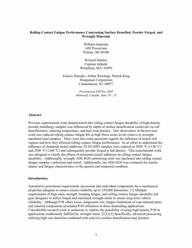
Relative to the effects of nickel rich regions resulting from elemental nickel additions, testing of powder forged FLN2-4405 verified the crack initiation and propagation nature of these microstructural phases. Figure 8 [2] showed cracking emanating from residual porosity within the locally densified surface region. In this earlier work, the effects of elemental nickel are quite dramatic from the failure analysis. In this SEM photomicrograph, the cracking follows areas of nickel rich microstructural features. Residual porosity in these areas occurs because of differences in strength of the various microstructural elements. In regard to the powder-forged samples of FLN2-4405, no evidence of residual porosity adjacent to nickel rich regions was found. Therefore, the assumption that the reduction in rolling contact fatigue life occurs because of these regions is determined empirically. However, nickel rich regions within the microstructure represent areas of areas of lower strength. Because of the subsurface stress characteristics of rolling contact fatigue, these low strength regions can result in potential sites for crack initiation and propagation.
11
Figure 8: Crack propagation through nickel rich regions of surface densified material. Mechanical Property Test Results Mechanical property testing of AISI 8620 showed a marked directionally in both fatigue and impact properties. Tensile testing did not show the same degree of directionality except for the elongation value. All testing was done on machined round samples. The reduction in fatigue and impact from longitudinal to transverse varied from approximately 40% for the carburized fatigues to greater than 50% for the notched impact samples. Un-notched impact testing did not show the degree of reduction from longitudinal to transverse. Directionality is important because many gears (spur gears) are actually loaded perpendicular to the principal working direction. Helical gears are loaded in both directions depending upon the helix angle of the gear (a 20% helical gear has the majority of its loading in the transverse direction). Often in literature databases, mechanical properties cited are longitudinal values with almost no mention of the transverse properties. Unlike wrought steels, P/M components are isotropic. There is some reduction in properties at the neutral axis of the part because of the reduction in density at this zone; however, with advanced part processing the reduction in density at the neutral zone is significantly reduced. Referring to Table 2, P/M offers nearly identical yield and tensile strengths but elongation and impact values are much reduced compared to wrought steels. Nearly equivalent rolling contact fatigue properties can be obtained through proper choice of alloy and processing condition. Fatigue values shown in Table 2 were generated using rotating bending fatigue samples. Modified single gear tooth bending fatigue shown values nearly equivalent to the tensile strength of AISI 8620 material. [12] It is important to note that this disparity is a function of the test bar geometry and test conditions.

12
Conclusions:
1. Rolling contact fatigue testing of powder forged FLN2-4405 demonstrated that elemental nickel additions are detrimental predominantly in surface densified material. Although elemental nickel does not lower the B50 life, the amount of scattering in life is greater. This greater scattering results from the residual porosity inherent with these phases and subsequent crack initiation and propagation tendencies for these phases. High temperature sintering does homogenize the elemental nickel additions thus promoting superior rolling contact fatigue life at lower contact stresses.
2. Rolling contact fatigue testing of AISI 8620 produced superior life at 2000 MPa relative to the baseline AISI 5120 material. However, testing at 2500 MPa showed the baseline material to have superior rolling contact fatigue life. This difference is related to the carburizing cycle employed.
3. It is desirable to use a lower carbon P/M material for gearing applications. A lower core carbon promotes enhanced surface densification and better case / core properties resulting from carburizing.
4. Comparison of powder forged FLN2-4405 to surface densified FLN2-4405 showed nearly identical rolling contact fatigue life at both high and low stress conditions. This indicates that surface densification may be an acceptable method to achieve nearly wrought properties provided subsequent heat treatments are identical.
5. Mechanical property testing of AISI 8620 material showed marked directionality from the longitudinal to the transverse direction. This directionality is greatest in fatigue and impact performance. P/M offers less directionality in properties.
References:
1. M. LeGault and J. Collins, �P/M Components in Heavy Duty H2 Transfer Case�, SAE Paper # 2004-01-0487.
2. William Jandeska, Richard Slattery, etal, �Rolling Contact Fatigue of Surface Densified FLN2-4405�, International Journal of Powder Metallurgy, Volume 41, Issue 3, 2005, pp. 49 �61.
3. R. Shivanath, etal, Vacuum Carburizatin of High Performance Automotive PM Parts, Industrial Heating, August 2003.
4. L. Sigl, G. Rau, M. Krehl, �Properties of Surface Densified P/M Gears� SAE Paper # 2005-01-0711.
5. V. A. Denise, etal, �Surface Densification of PM Materials�, Advances in Powder Metallurgy and Particulate Materials � 2000, Metal Powders Industry Federation, Princeton, NJ 08540 pp. 3-127 to 3-137.
6. Darle Dudley, �Handbook of Practical Gear Design�, p 2-14, McGraw-Hill Book Company, 1984.
7. K. Lipp, G. Hoffmann, �Design for Rolling Contact Fatigue�, Advances in Powder Metallurgy and Particulate Materials � 2002, Metal Powder Industries Federation, Princeton, NJ, 08540 pp.5-28 to 5-51.
8. MPIF Standard 35, 2003 Edition, Metal Powders Industry Federation, Princeton NJ. 9. Joe Chen, John Flynn, Geoff Semrau, �Gear Surface Durability Development to Enhance
Transmission Power Density�, Gear Technology, July / August 2002, pp. 20-25. 10. R. Leachman, Private Communication 11. H. Sanderow, �Final Report, Rolling Contact Fatigue (RCF) Test Program�, Prepared by
the Center for Powder Metal Technology (CPMT), September 2001. 12. www.Mat web.com.