Embed Size (px)
Citation preview

Engineering manual No. 28
Updated: 02/2018
1
Rock slope – rock wedge stability
Program: Rock stability
File: Demo_manual_28.gsk
The aim of the chapter of this engineering manual is to explain a rock slope stability situated in a
tectonically affected semirock to hard rock in a selected excavation.
The evaluated excavation outcrop is formed by a system of tectonic faults and joints arranged into
a 3D mostly unstable rock wedges.
Task Description
The story of the outcrop went through excavation works related to the construction of Votice two
track railway tunnel blasted in Paleozoic ingenuous rock. There are structural joints infilled by micro
granites, aplites and party amphibolite-biotitic granites (the most common rock types).
The evaluated outcrop is a typical one with non-feasible orientation of shear planes, those planes
affects the rock face stability and form sliding rock wedges (Fig 1).
Figure 1: Western slope of the excavation pit, L. Marik photography
The geological investigation found out, that the excavation stability is affected by three to four
systems of faults and joints. The rock mass is fragmented into a wide scale of rock stones and blocks
and wide boulders with a size up to scale of several meters.
The rock faults dip-direction form a sharp angle smaller than 45 degrees with the excavation slope
and the slope dips with 65 to 80 degrees angle to the east (Fig. 2).

2
Figure 2: Lambert orthogonal projection diagram with the most common discontinuities, Z 70/70
(dip-direction/dip) is the orientation of the excavation rock-face.
These not feasible orientations of discontinuities affected the designed excavation works due to
wide unstable rock wedges sliding down the slope (Fig. 3). The not feasible orientations was
unexpected before the excavation.

3
Figure 3: Main shear and joint planes with the excavation pit cross-section
This unfeasible situation of the excavation slope forces a design of some stabilization structures –
design of the rock active-wedges stabilization. The sliding rock wedge stabilization is described in this
engineering manual.
Note: Each natural rock mass (by a human hand) contains at least two main systems of
discontinuities affecting a rock-slope stability. However, when a rock mass was fractured by low
amount of discontinuities system, the system is the keystone for a global stability evaluation of a failure
mechanism and an instability situation.
Settings
A process of the unstable 3D rock wedge stabilization design is described later on the example of a
selected cross-section of an excavation of a tunnel portal. The stabilization is designed for a 100 years
long durability and the required factor of safety is 1.5.
On the base of the geological investigation, the granite and aplite rock samples classified as hard
rock of types R2 and R3 (ČSN 73 6133), have following mechanical properties: c = 15 – 60 MPa, unit
weight = 27 kN/m3 , effective friction angle ' = 32 – 42 °, effective cohesion c‘ = 100 – 150 kPa,
Poisson ratio = 0.20, a deformation modulus 100 – 200 MPa. Hence, here are several mechanical
parameters showing high deformation characteristics of the rock mass measured on a small size rock

4
samples, overall strength of the mass is lower due to high fracturing by shear failures (size effect). The
shear strength on planes can converge to zero.
Hydrogeological background shows only simple conditions and there is no water damping joint of
the rock face there. Random wet springs are related to a higher rain activity and a snow melting. There
is no water table related to the rock face. Rock joints’ orientations were measured by a designer’s
structural geologist. The evaluated rock excavation slope’s orientation is Z 180/15 (dip-direction/dip)
and investigated typical failures’ orientations are 20/80 and 225/70. The shear strength measured on
the shear planes is ‘ = 15 ° and cohesion c‘= 5 kPa.
Solution
The slope stability assessment of the sliding rock wedge in the selected cross-section and its
stabilization is to be tuned with factors of safety (the main reason is a comparison with hand
calculations). Each calculation step of the design is described in the following text.

5
Task’s Settings
Settings of the required computation related to a factor of safety and a rock slope failure
In the frame “Settings“ press the button “Settings List“ and select “Standard – Safety Factors“ and
confirm via “OK“.
“Settings” frame “Settings list“
Here, in the window also set “Earth wedge“ up.
Note: The application Rock Slope can evaluate a broken rock wall by a shear failure (rock slides)
using a planar and/or a polygonal shear plane and a rock wedge.
Basic Geometry of a Surface and a Rock Face
3D geometry of the evaluated rock slope (terrain) and excavation pit (rock face) is to be set up in a
frame named “Geometry“. Input of the slope or the surface of terrain orientation is via a dip-
direction/dip way, those data were measured during the structural geological investigation – inputted
data are placed into a table. The rock face height is 13 m. Inputted planes are shown in Lambert
orthogonal projection and an arc represents a projection (a cross-cut) of a shear plane with Lambert
lower hemisphere.

6
Note: In a situation when a structural geological investigation is not present, the 3D rock face
orientation could be given by a geodetic surveying by the three points for each plane (e.g. 2x bottom
of the slope, top of the slope). Another possibility is by the use of a measuring tape or a
photogrammetry. In a difficult condition, there is an option to evaluate the slope height by a ratio
between a man and the slope face.
Orientation settings (terrain and rock face)
Dip-direction [°] Dip [°]
Rock face 257 76
Terrain (upper face line) 180 15
“Geometry” frame
Shear Failure Orientation Input
3D shear failure orientation (geometry) shall be set in “Sl. Surface” window. Input of the orientation
of the shear failures is via dip-direction/dip and investigated by a structural geological investigation –
there are inputted data in the table there. The input goes through a graphical window showing the

7
orientation data in Lambert orthogonal projection. An arc shows a cross-cut of a plane on a lower
Lambert’s hemisphere.
Rock face and Terrain geometry data
Dip-direction [°] Dip [°]
Slip surface 1 20 80
Slip surface 2 225 70
“Sl. surface” frame

8
It is also possible to see defined earth wedge using “3D view”.
3D show of the rock wedge in 3D window
Note: 3D shear planes orientations are related to geographical coordinates. These coordinates are
related to the orientation of north in a horizontal direction and to the center of gravity in a vertical
direction. The orientation was measured with a help of a geological compass. The main failures could
be described by geophysical measurements.
Input of Rock and Shear Planes Properties
The mechanical properties of rock mass are described in the “Parameters“ frame. Here a unit
weight of the material forming the rock mass and a shape of the rock shear plane are set to Mohr-
Coulomb model up. A granite’s unit weight is = 27 kN/m3 and shear properties obtained by shear
tests on both former discussed shear planes are ’ = 15 ° and c‘‘= 5 kPa.

9
“Parameters” frame
Note: The easiest test of a shear strength on a shear plane is a movement of two rock block taken
from a rock mass (separated by a shear plane). This measurement is feasible just for planar planes
without any peaks or holes (dilatation units). If the shear plane is not planar, properties should be
obtained by a computation in a selected window or by a difficult in situ test.
Underground Water
Unground water table is set up in “Water” window. On the base of the hydrogeological investigation
there is no underground water impact.
Settings of the Design Phase
In “Stage Settings“ window a design phase of the computation is selected. In our situation with the
100 years durability of the rock face stability of the tunnel portal section a permanent stability situation
is chosen.
Computation
Computation process runs a press of an icon of “Analysis“. Basic results and others possible
selections appears in a window of “Analysis“. Detailed results are to be operated by button “In Detail“
or in an application protocol. In our situation 1.32 factor of safety was obtained. The rock wedge’s
stability is not in an accord with safety requirements (F ≥ 1.5). In a large time scale a possibility of local

10
surface instabilities could affect the rock mass. Regarding to this fact some technical solution to
increase the wedge stability shall be designed.
Analysis – stage 1
Stability Increment Solution Design
Increase of the stability of the rock wedge is possible via a change of the slope shape to a lower
slope dip or an excavation of small benches decreases the overall dip. This solution brings a large bulk
of earth works and a larger occupied area requirement, due to these given arguments the discussed
solution is expensive. A second option is to keep the actual rock slope shape and fix stability of the
sliding rock wedge via rock bolts (anchors) or nails. The second option is described in the following
text.
The anchor design is proven in the second phase of the analysis via the “+“ button which is close to
the “Phase“ button.
The next phase addition
11
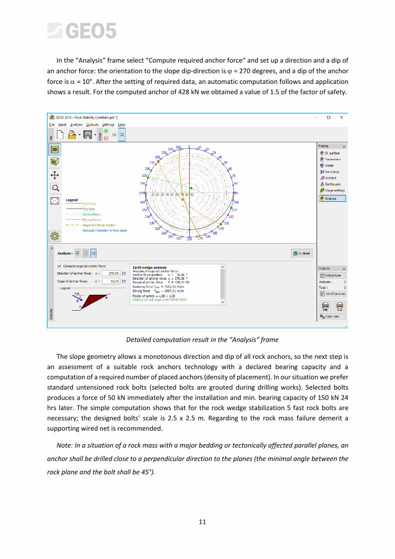
In the “Analysis“ frame select “Compute required anchor force“ and set up a direction and a dip of
an anchor force: the orientation to the slope dip-direction is = 270 degrees, and a dip of the anchor
force is = 10°. After the setting of required data, an automatic computation follows and application
shows a result. For the computed anchor of 428 kN we obtained a value of 1.5 of the factor of safety.
Detailed computation result in the “Analysis“ frame
The slope geometry allows a monotonous direction and dip of all rock anchors, so the next step is
an assessment of a suitable rock anchors technology with a declared bearing capacity and a
computation of a required number of placed anchors (density of placement). In our situation we prefer
standard untensioned rock bolts (selected bolts are grouted during drilling works). Selected bolts
produces a force of 50 kN immediately after the installation and min. bearing capacity of 150 kN 24
hrs later. The simple computation shows that for the rock wedge stabilization 5 fast rock bolts are
necessary; the designed bolts’ scale is 2.5 x 2.5 m. Regarding to the rock mass failure demerit a
supporting wired net is recommended.
Note: In a situation of a rock mass with a major bedding or tectonically affected parallel planes, an
anchor shall be drilled close to a perpendicular direction to the planes (the minimal angle between the
rock plane and the bolt shall be 45°).
12
Conclusion
Our preliminary result of the discussed analysis of the rock wedge shows the factor of safety F=1.32
what is not satisfied value. This result forced the option of the technical solution of the slope stability
increasing. We decided to select the anchor option of the wedge stabilization due to the economic
feasibility. During the second phase of the design the anchor force and the anchor dip were set up.
Due to a necessity of the monotonous bolts’ dip in overall rock mass, the suitable rock bolt type in the
computed density was selected.