Embed Size (px)
Citation preview
RNAV Training for ATC RNAV Training for ATC
© Air Traffic Control Association Japan, All Right Reserved
20072007
Air Traffic Control Association Japan
SAMPLE
Important Notice
• This material is intended for information purpose only.
• ATCAJ and JCAB are exempt from claims for any loss
or damage caused as a result of the use of this material.
• ATC Procedures and other methods indicated in this
material are those applicable in Japan (Fukuoka FIR).
It may be possible to implement other solutions in
other states so far as they are in accordance with
relevant ICAO regulations.
© Air Traffic Control Association Japan, All Right Reserved
Objectives of TrainingObjectives of Training
�� Understand the Principle of RNAVUnderstand the Principle of RNAV
�� Understand the Concept of Procedure Design CriteriaUnderstand the Concept of Procedure Design Criteria
�� Understand the Flight Operation and Performance of AircraftUnderstand the Flight Operation and Performance of Aircraft
�� Understand the ATC Procedures related to Understand the ATC Procedures related to RNAVRNAV Performance Performance
RequirementsRequirements
© Air Traffic Control Association Japan, All Right Reserved
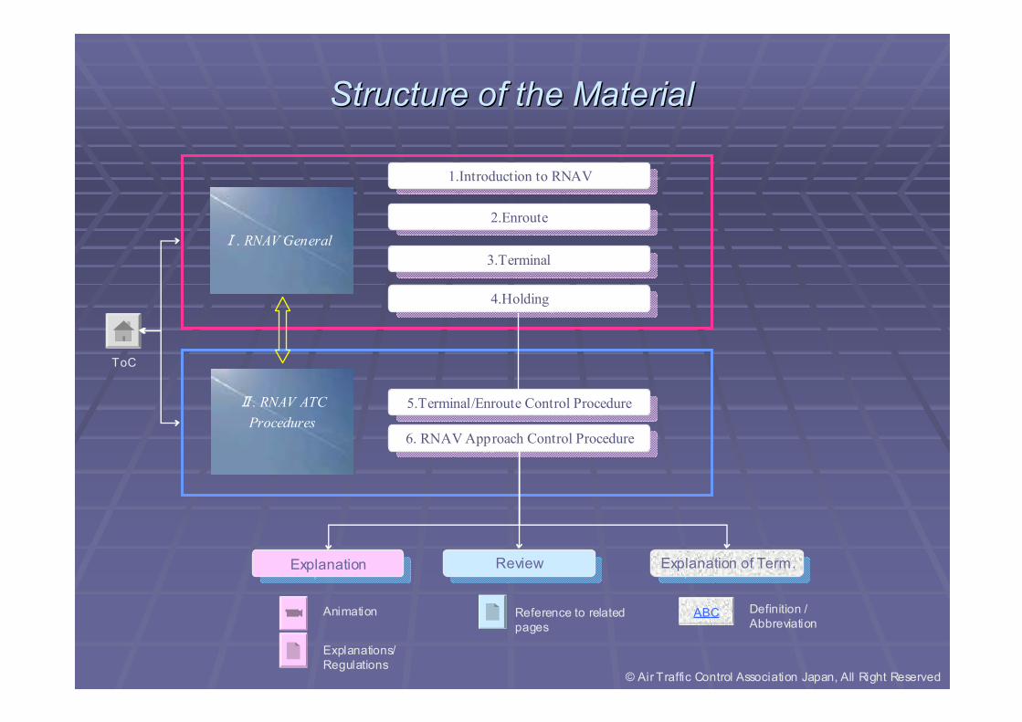
Structure of the MaterialStructure of the Material
ExplanationExplanation
Animation
Explanations/
Regulations
ToC
1.Introduction to RNAV1.Introduction to RNAV
2.Enroute2.Enroute
3.Terminal3.Terminal
4.Holding4.Holding
6. RNAVApproach Control Procedure6. RNAVApproach Control Procedure
5.Terminal/Enroute Control Procedure5.Terminal/Enroute Control Procedure
Ⅰ. RNAV General
RNAVGeneralⅡ. RNAV ATC
Procedures
Explanation of Term.Explanation of Term.
ABC Definition /
Abbreviation
ReviewReview
Reference to related
pages
© Air Traffic Control Association Japan, All Right Reserved
I. I. RNAVRNAV GeneralGeneral
II. RNAV ATC procedures© Air Traffic Control Association Japan, All Right Reserved
3. Terminal
4. Holding2. Enroute
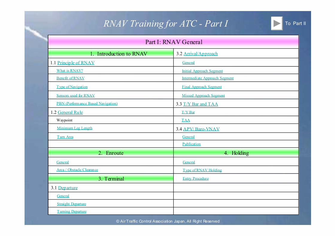
Part I: RNAV General
To Part II
1. Introduction to RNAV
1.1 Principle of RNAV
What is RNAV?
Benefit of RNAV
Type of Navigation
Sensors used for RNAV
PBN (Performance Based Navigation)
1.2 General Rule
Waypoint
Minimum Leg Length
Turn Area
General
Area / Obstacle Clearance
3.1 Departure
General
Straight Departure
Turning Departure
3.2 Arrival/Approach
General
Initial Approach Segment
Intermediate Approach Segment
Final Approach Segment
Missed Approach Segment
3.3 T/Y Bar and TAA
T/Y Bar
TAA
3.4 APV/ Baro-VNAV
General
Publication
General
Type of RNAV Holding
Entry Procedure
RNAV Training for ATC - Part I
© Air Traffic Control Association Japan, All Right Reserved
1.1 Principle of RNAV
1.2 General Rule
1. Introduction to RNAV
© Air Traffic Control Association Japan, All Right Reserved
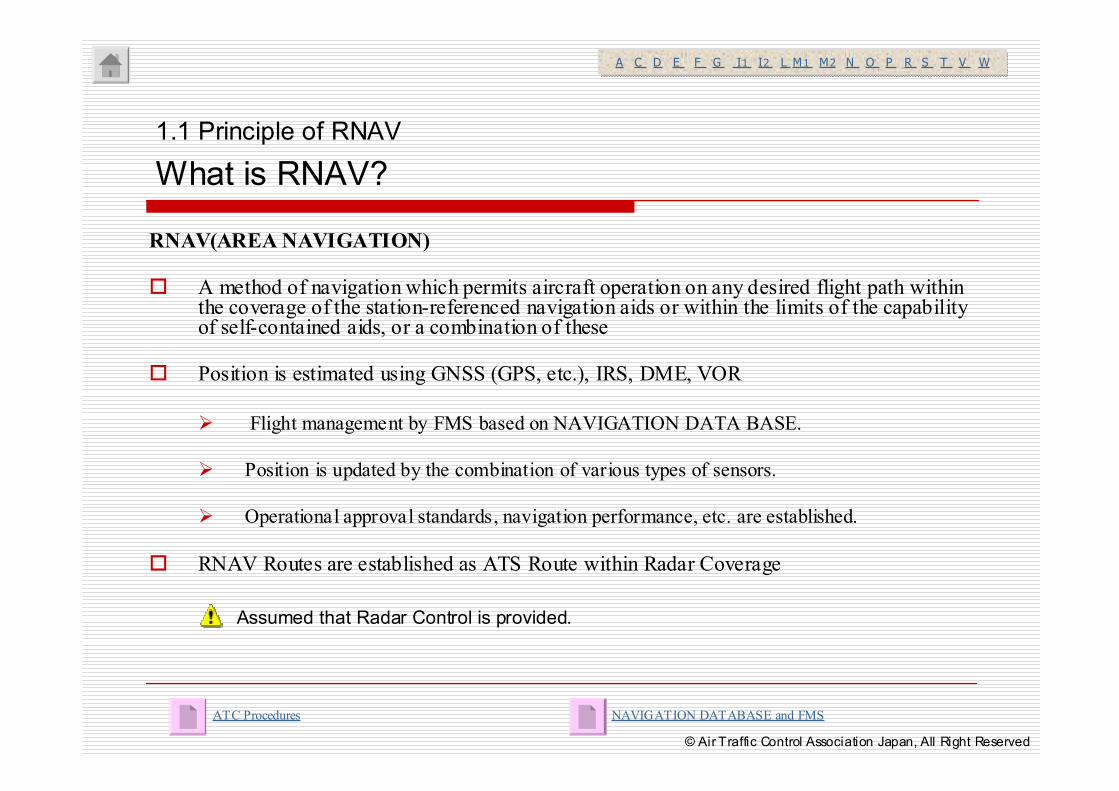
RNAV(AREA NAVIGATION)
� A method of navigation which permits aircraft operation on any desired flight path within the coverage of the station-referenced navigation aids or within the limits of the capability of self-contained aids, or a combination of these
� Position is estimated using GNSS (GPS, etc.), IRS, DME, VOR
� Flight management by FMS based on NAVIGATION DATA BASE.
� Position is updated by the combination of various types of sensors.
� Operational approval standards, navigation performance, etc. are established.
� RNAV Routes are established as ATS Route within Radar Coverage
1.1 Principle of RNAV
What is RNAV?
NAVIGATION DATABASE and FMSATC Procedures
A C D E F G I1 I2 L M1 M2 N O P R S T V WA C D E F G I1 I2 L M1 M2 N O P R S T V W
Assumed that Radar Control is provided.
© Air Traffic Control Association Japan, All Right Reserved
1.1 Principle of RNAV
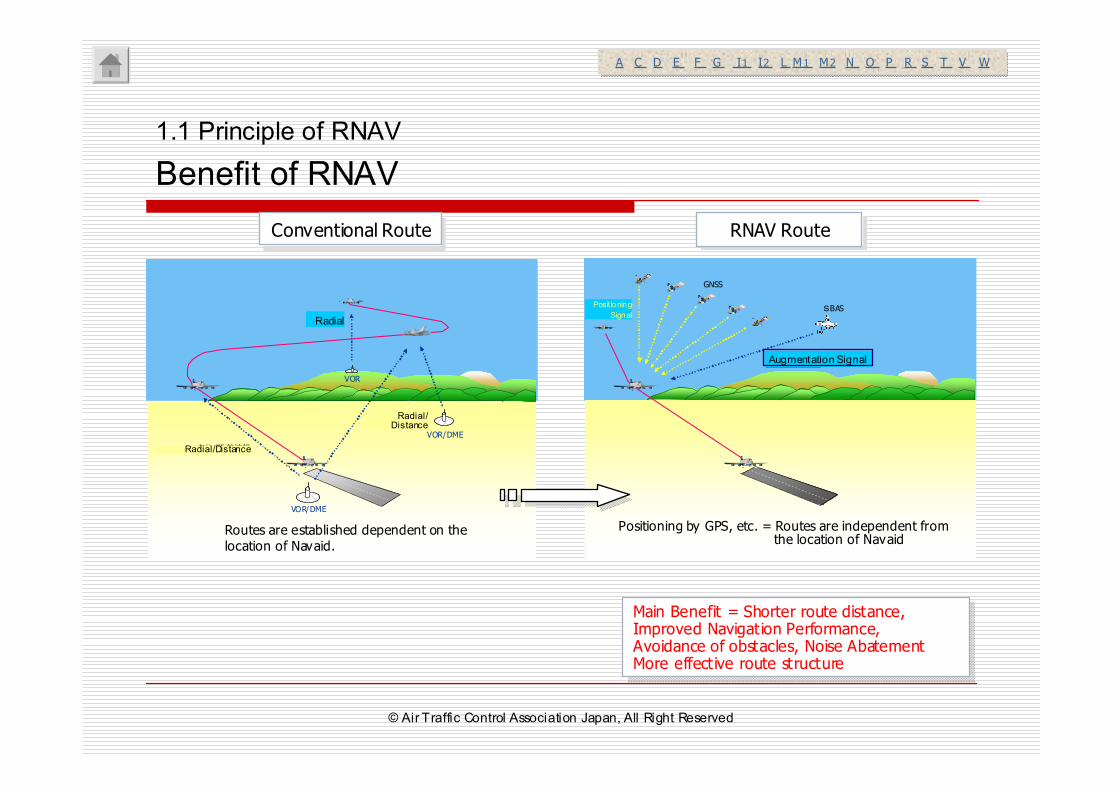
Benefit of RNAV
Main Benefit = Shorter route distance, Improved Navigation Performance, Avoidance of obstacles, Noise AbatementMore effective route structure
Main Benefit = Shorter route distance, Improved Navigation Performance, Avoidance of obstacles, Noise AbatementMore effective route structure
A C D E F G I1 I2 L M1 M2 N O P R S T V WA C D E F G I1 I2 L M1 M2 N O P R S T V W
SBAS
GNSS
補強信号
測位信号 SBAS
GNSS
補強信号
測位信号
Conventional RouteConventional Route RNAV RouteRNAV Route
VOR
VOR/DME
VOR/DME
方位情報
方位/距離情報
方位/距離情報
VOR
VOR/DME
VOR/DME
方位情報
方位/距離情報
方位/距離情報
VOR
VOR/DME
VOR/DME
方位情報
方位/距離情報
方位/距離情報
Routes are established dependent on the location of Navaid.
Positioning by GPS, etc. = Routes are independent from the location of Navaid
Radial
Radial/Distance
Radial/Distance
Augmentation Signal
Positioning
Signal
© Air Traffic Control Association Japan, All Right Reserved
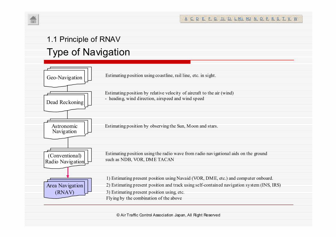
Geo-Navigation Estimating position using coastline, rail line, etc. in sight.
Dead Reckoning
Estimating position by relative velocity of aircraft to the air (wind)
- heading, wind direction, airspeed and wind speed
AstronomicNavigation
Estimating position by observing the Sun, Moon and stars.
(Conventional)Radio Navigation
Estimating position using the radio wave from radio navigational aids on the ground
such as NDB, VOR, DME TACAN
Area Navigation
(RNAV)
1) Estimating present position using Navaid (VOR, DME, etc.) and computer onboard.
2) Estimating present position and track using self-contained navigation system (INS, IRS)
3) Estimating present position using, etc.
Flying by the combination of the above
1.1 Principle of RNAV
Type of Navigation
A C D E F G I1 I2 L M1 M2 N O P R S T V WA C D E F G I1 I2 L M1 M2 N O P R S T V W
© Air Traffic Control Association Japan, All Right Reserved
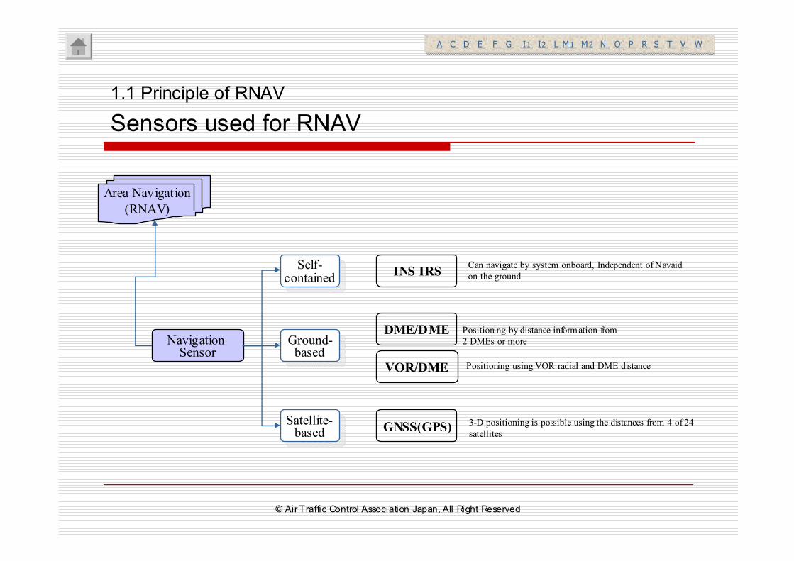
Area Navigation
(RNAV)
1.1 Principle of RNAV
Sensors used for RNAV
DME/DME
INS IRS
VOR/DME
GNSS(GPS)
Self-contained
Self-contained
Ground-based
Ground-based
Satellite-based
Satellite-based
Navigation Sensor
Can navigate by system onboard, Independent of Navaid
on the ground
Positioning by distance information from
2 DMEs or more
Positioning using VOR radial and DME distance
3-D positioning is possible using the distances from 4 of 24
satellites
A C D E F G I1 I2 L M1 M2 N O P R S T V WA C D E F G I1 I2 L M1 M2 N O P R S T V W
© Air Traffic Control Association Japan, All Right Reserved
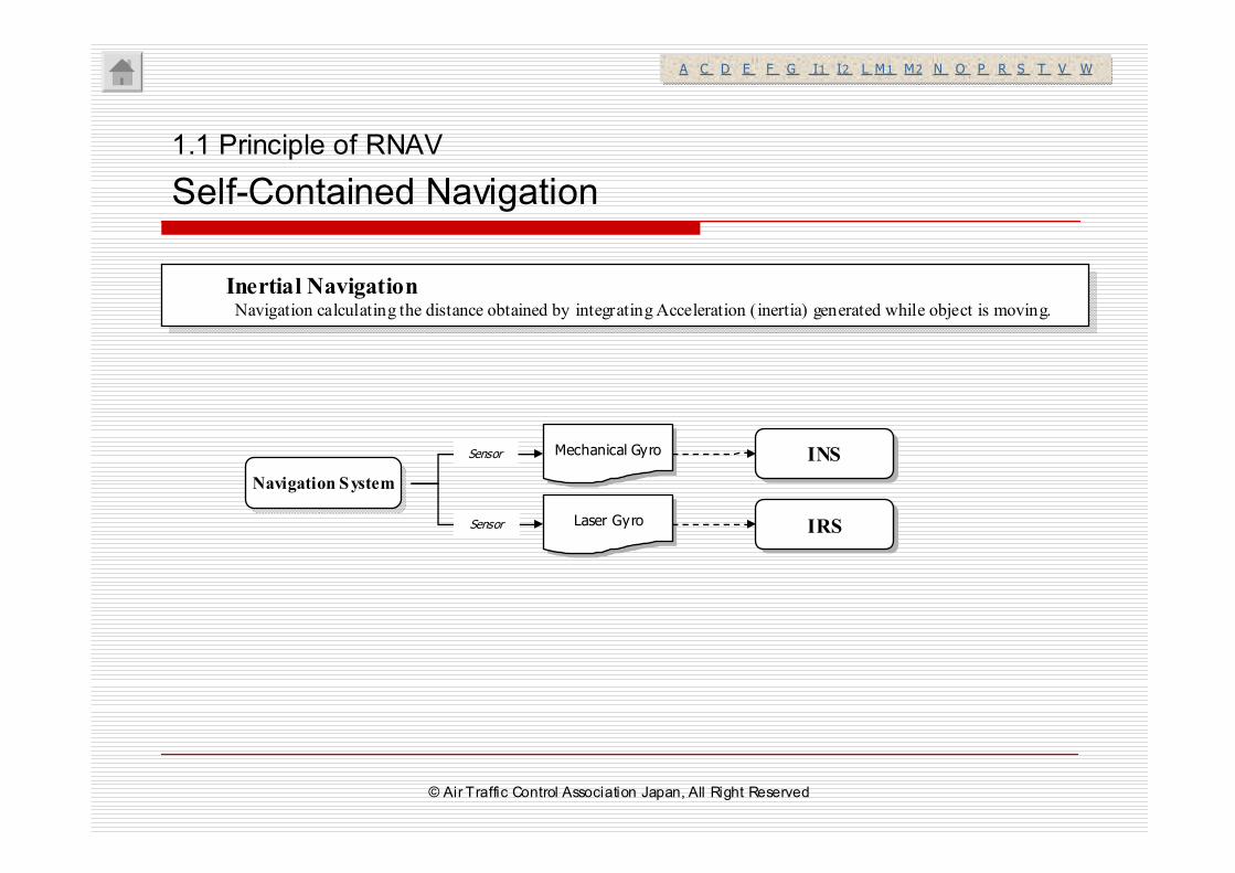
1.1 Principle of RNAV
Self-Contained Navigation
Inertial NavigationNavigation calculating the distance obtained by integrating Acceleration (inertia) generated while object is moving.
Inertial NavigationNavigation calculating the distance obtained by integrating Acceleration (inertia) generated while object is moving.
Navigation SystemNavigation System
IRSIRS
Mechanical GyroMechanical Gyro
Laser GyroLaser Gyro
INSINS
Sensor
Sensor
A C D E F G I1 I2 L M1 M2 N O P R S T V WA C D E F G I1 I2 L M1 M2 N O P R S T V W
© Air Traffic Control Association Japan, All Right Reserved
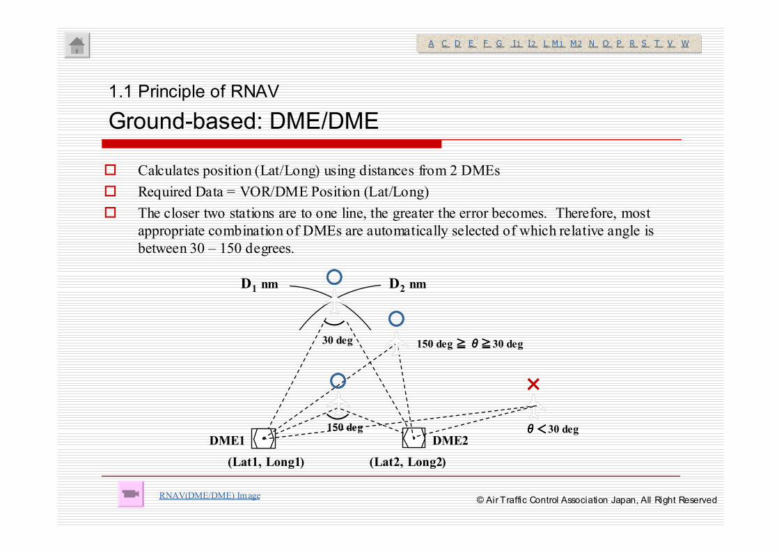
� Calculates position (Lat/Long) using distances from 2 DMEs
� Required Data = VOR/DME Position (Lat/Long)
� The closer two stations are to one line, the greater the error becomes. Therefore, most
appropriate combination of DMEs are automatically selected of which relative angle is
between 30 – 150 degrees.
1.1 Principle of RNAV
Ground-based: DME/DME
RNAV(DME/DME) Image
A C D E F G I1 I2 L M1 M2 N O P R S T V WA C D E F G I1 I2 L M1 M2 N O P R S T V W
DME1 DME2
(Lat1, Long1) (Lat2, Long2)
D1 nm D2 nm
30 deg
150 deg
××××
○○○○
○○○○150 deg ≧≧≧≧ θ≧θ≧θ≧θ≧30 deg
θθθθ<<<<30 deg
○○○○
© Air Traffic Control Association Japan, All Right Reserved
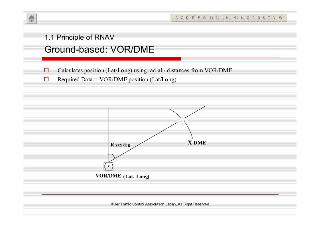
� Calculates position (Lat/Long) using radial / distances from VOR/DME
� Required Data = VOR/DME position (Lat/Long)
VOR/DME (Lat, Long)
R xxx deg X DME
1.1 Principle of RNAV
Ground-based: VOR/DME
A C D E F G I1 I2 L M1 M2 N O P R S T V WA C D E F G I1 I2 L M1 M2 N O P R S T V W
© Air Traffic Control Association Japan, All Right Reserved
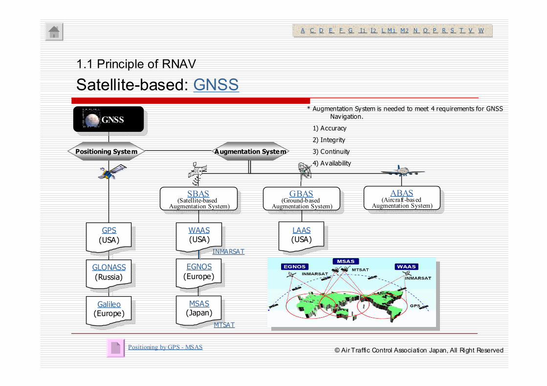
1.1 Principle of RNAV
Satellite-based: GNSS
SBAS(Satellite-based
Augmentation System)
SBAS(Satellite-based
Augmentation System)
GPS
(USA)
GPS
(USA)
GLONASS
(Russia)
GLONASS
(Russia)
Galileo(Europe)
Galileo(Europe)
WAAS(USA)
WAAS(USA)
EGNOS
(Europe)
EGNOS
(Europe)
MSAS(Japan)
MSAS(Japan)
LAAS(USA)
LAAS(USA)
GBAS(Ground-based
Augmentation System)
GBAS(Ground-based
Augmentation System)
Positioning System Augmentation System
ABAS(Aircraft -based
Augmentation System)
ABAS(Aircraft -based
Augmentation System)
GNSSGNSS
INMARSAT
MTSAT
* Augmentation System is needed to meet 4 requirements for GNSS Navigation.
1) Accuracy
2) Integrity
3) Continuity
4) Availability
Positioning by GPS - MSAS
A C D E F G I1 I2 L M1 M2 N O P R S T V WA C D E F G I1 I2 L M1 M2 N O P R S T V W
© Air Traffic Control Association Japan, All Right Reserved
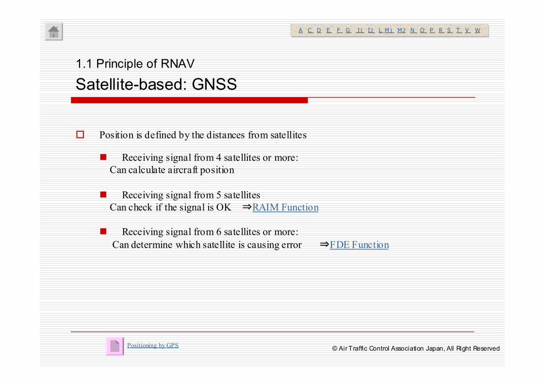
� Position is defined by the distances from satellites
� Receiving signal from 4 satellites or more:
Can calculate aircraft position
� Receiving signal from 5 satellites
Can check if the signal is OK ⇒RAIM Function
� Receiving signal from 6 satellites or more:
Can determine which satellite is causing error ⇒FDE Function
1.1 Principle of RNAV
Satellite-based: GNSS
Positioning by GPS
A C D E F G I1 I2 L M1 M2 N O P R S T V WA C D E F G I1 I2 L M1 M2 N O P R S T V W
© Air Traffic Control Association Japan, All Right Reserved
1.1 Principle of RNAV
Satellite Based: Navigation Requirements
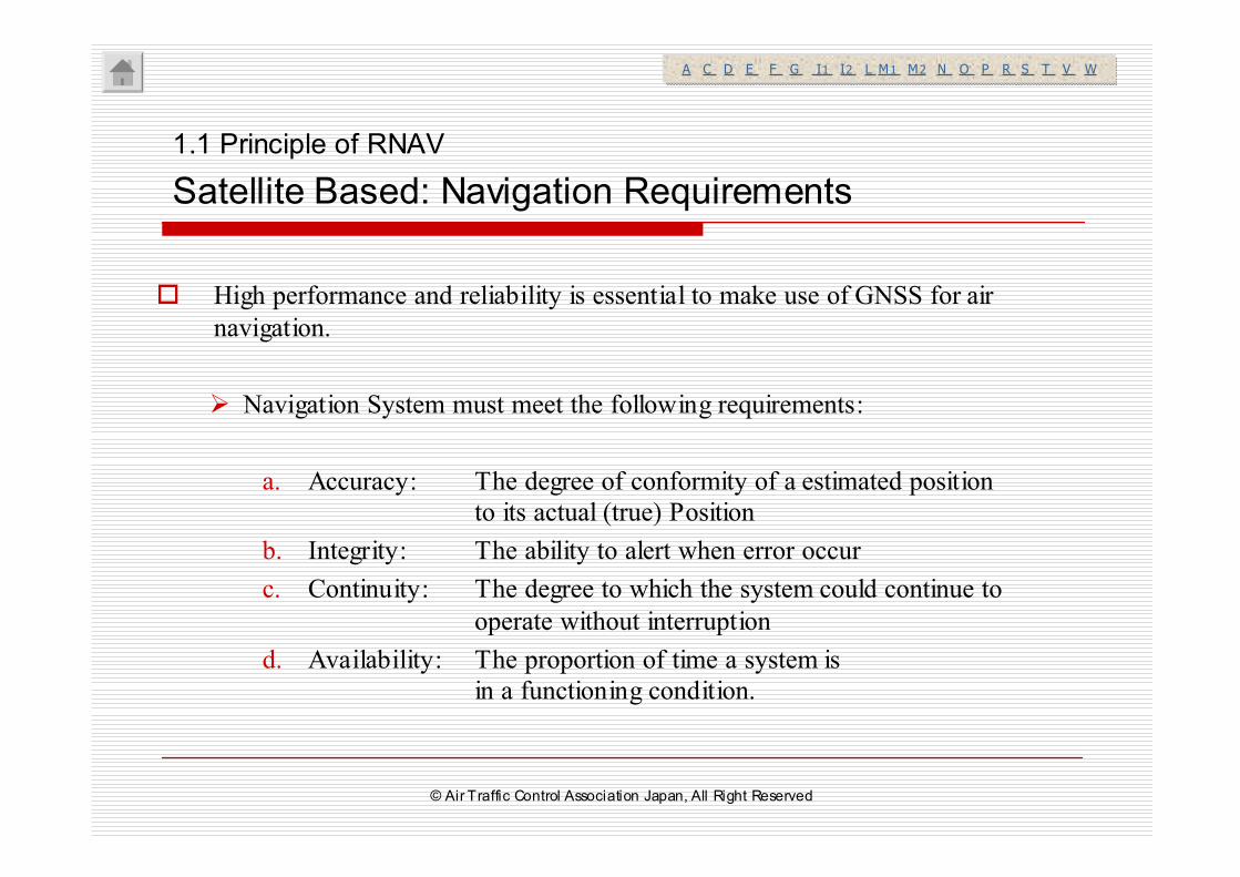
� High performance and reliability is essential to make use of GNSS for air
navigation.
� Navigation System must meet the following requirements:
a. Accuracy: The degree of conformity of a estimated position
to its actual (true) Position
b. Integrity: The ability to alert when error occur
c. Continuity: The degree to which the system could continue to
operate without interruption
d. Availability: The proportion of time a system is
in a functioning condition.
A C D E F G I1 I2 L M1 M2 N O P R S T V WA C D E F G I1 I2 L M1 M2 N O P R S T V W
© Air Traffic Control Association Japan, All Right Reserved
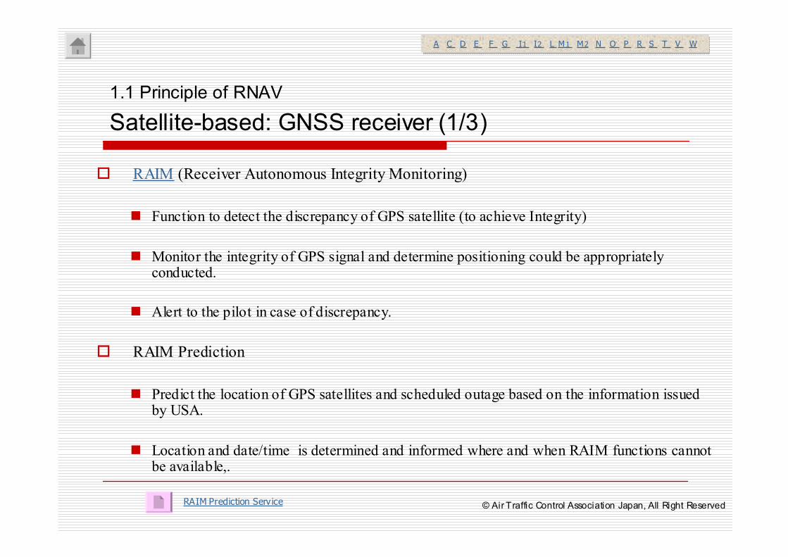
� RAIM (Receiver Autonomous Integrity Monitoring)
� Function to detect the discrepancy of GPS satellite (to achieve Integrity)
� Monitor the integrity of GPS signal and determine positioning could be appropriately conducted.
� Alert to the pilot in case of discrepancy.
� RAIM Prediction
� Predict the location of GPS satellites and scheduled outage based on the information issued by USA.
� Location and date/time is determined and informed where and when RAIM functions cannot be available,.
RAIM Prediction Service
A C D E F G I1 I2 L M1 M2 N O P R S T V WA C D E F G I1 I2 L M1 M2 N O P R S T V W
1.1 Principle of RNAV
Satellite-based: GNSS receiver (1/3)
© Air Traffic Control Association Japan, All Right Reserved
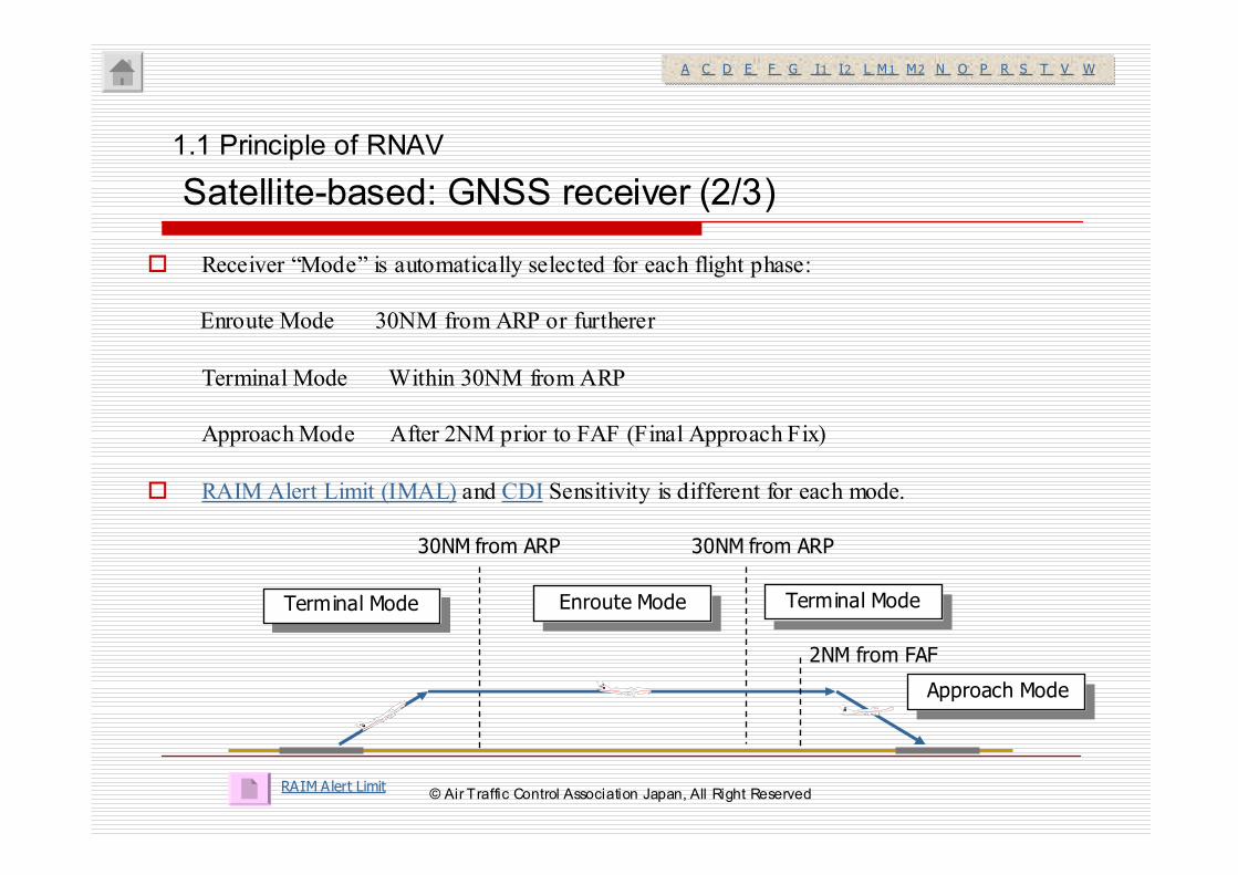
� Receiver “Mode” is automatically selected for each flight phase:
Enroute Mode 30NM from ARP or furtherer
Terminal Mode Within 30NM from ARP
Approach Mode After 2NM prior to FAF (Final Approach Fix)
� RAIM Alert Limit (IMAL) and CDI Sensitivity is different for each mode.
1.1 Principle of RNAV
Satellite-based: GNSS receiver (2/3)
RAIM Alert Limit
A C D E F G I1 I2 L M1 M2 N O P R S T V WA C D E F G I1 I2 L M1 M2 N O P R S T V W
2NM from FAF
Terminal ModeTerminal Mode Enroute ModeEnroute Mode Terminal ModeTerminal Mode
Approach ModeApproach Mode
30NM from ARP30NM from ARP
AT CA J ●AT CA J ●
ATCAJ
●
ATCAJ
●A TC AJ ●A TC AJ ●
© Air Traffic Control Association Japan, All Right Reserved
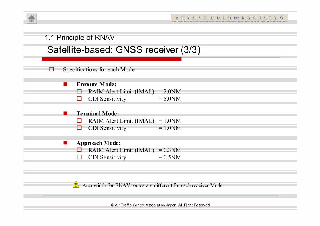
� Specifications for each Mode
� Enroute Mode:
� RAIM Alert Limit (IMAL) = 2.0NM
� CDI Sensitivity = 5.0NM
� Terminal Mode:
� RAIM Alert Limit (IMAL) = 1.0NM
� CDI Sensitivity = 1.0NM
� Approach Mode:
� RAIM Alert Limit (IMAL) = 0.3NM
� CDI Sensitivity = 0.5NM
1.1 Principle of RNAV
Satellite-based: GNSS receiver (3/3)
A C D E F G I1 I2 L M1 M2 N O P R S T V WA C D E F G I1 I2 L M1 M2 N O P R S T V W
Area width for RNAV routes are different for each receiver Mode.
© Air Traffic Control Association Japan, All Right Reserved
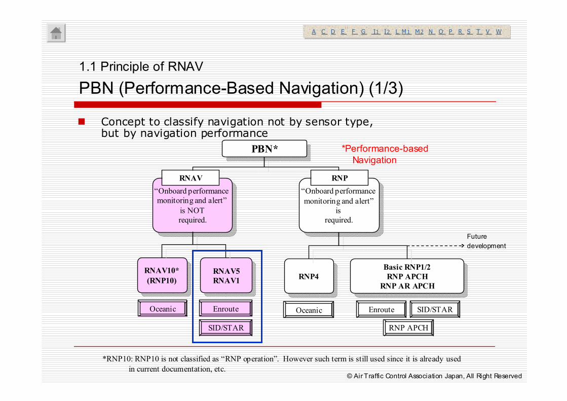
� Concept to classify navigation not by sensor type, but by navigation performance
1.1 Principle of RNAV
PBN (Performance-Based Navigation) (1/3)
A C D E F G I1 I2 L M1 M2 N O P R S T V WA C D E F G I1 I2 L M1 M2 N O P R S T V W
*RNP10: RNP10 is not classified as “RNP operation”. However such term is still used since it is already used
in current documentation, etc.
PBN*PBN*
“Onboard performance
monitoring and alert”
is NOT
required.
“Onboard performance
monitoring and alert”
is NOT
required.
RNAV10*
(RNP10)
RNAV10*
(RNP10)RNAV5
RNAV1
RNAV5
RNAV1 RNP4RNP4
Basic RNP1/2
RNP APCH
RNP AR APCH
Basic RNP1/2
RNP APCH
RNP AR APCH
“Onboard performance
monitoring and alert”
is
required.
“Onboard performance
monitoring and alert”
is
required.
Oceanic Enroute
SID/STAR
Oceanic
RNP APCH
RNAV RNP
Enroute SID/STAR
Future
development
*Performance-based
Navigation
© Air Traffic Control Association Japan, All Right Reserved
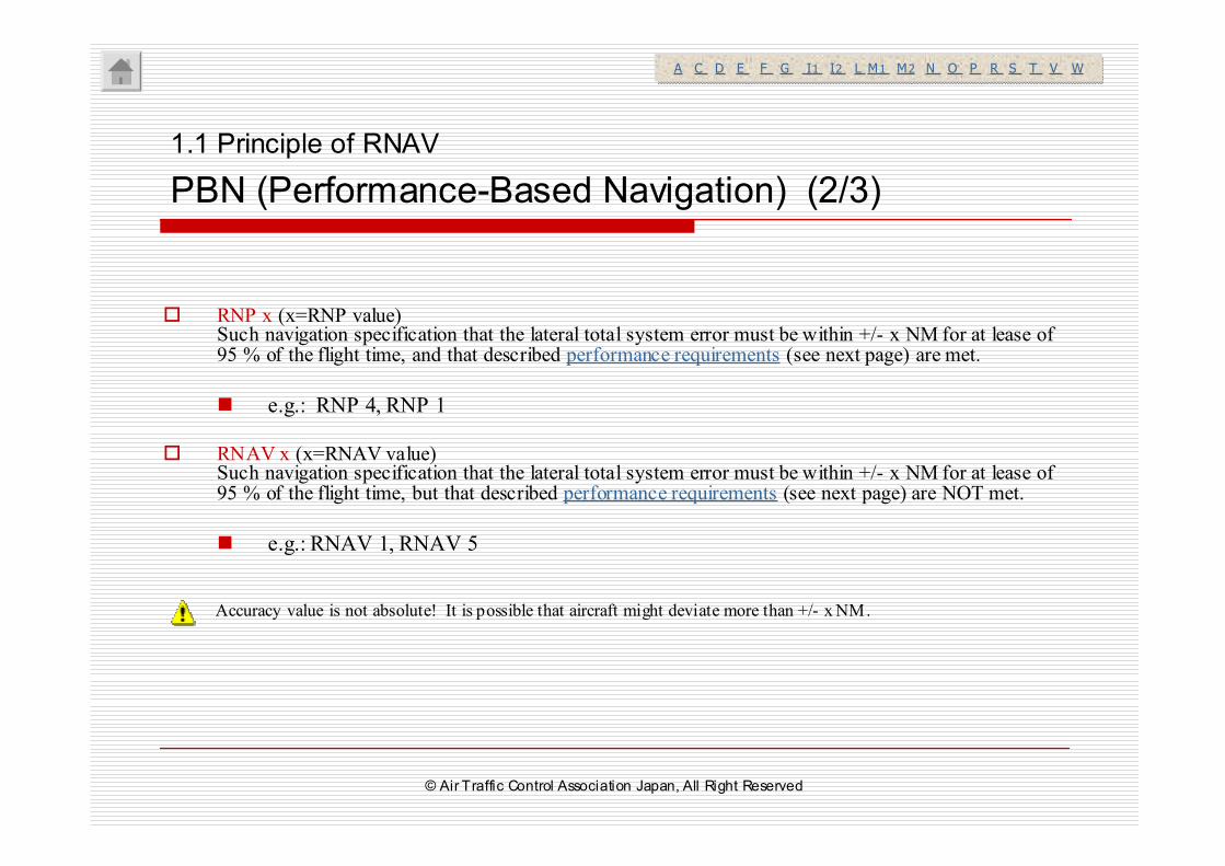
� RNP x (x=RNP value)Such navigation specification that the lateral total system error must be within +/- x NM for at lease of95 % of the flight time, and that described performance requirements (see next page) are met.
� e.g.: RNP 4, RNP 1
� RNAV x (x=RNAV value)Such navigation specification that the lateral total system error must be within +/- x NM for at lease of 95 % of the flight time, but that described performance requirements (see next page) are NOT met.
� e.g.: RNAV 1, RNAV 5
1.1 Principle of RNAV
PBN (Performance-Based Navigation) (2/3)
A C D E F G I1 I2 L M1 M2 N O P R S T V WA C D E F G I1 I2 L M1 M2 N O P R S T V W
Accuracy value is not absolute! It is possible that aircraft might deviate more than +/- x NM.
© Air Traffic Control Association Japan, All Right Reserved
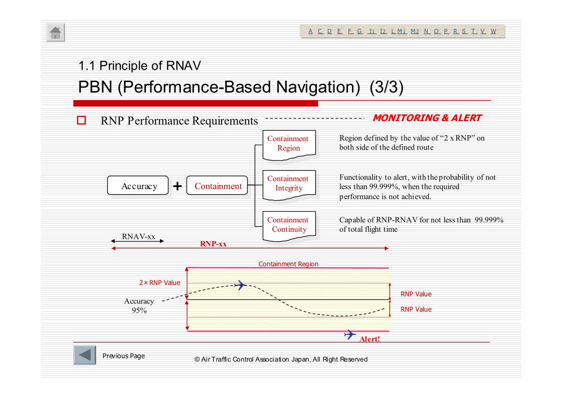
� RNP Performance Requirements
1.1 Principle of RNAV
PBN (Performance-Based Navigation) (3/3)
AccuracyAccuracy ContainmentContainment
Containment
Region
Containment
Region
Containment
Integrity
Containment
Integrity
Containment
Continuity
Containment
Continuity
+
RNAV-xxRNP-xx
Region defined by the value of “2 x RNP” on
both side of the defined route
Functionality to alert, with the probability of not
less than 99.999%, when the required
performance is not achieved.
Capable of RNP-RNAV for not less than 99.999%
of total flight time
Previous Page
MONITORING & ALERT
A C D E F G I1 I2 L M1 M2 N O P R S T V WA C D E F G I1 I2 L M1 M2 N O P R S T V W
2×RNP Value
RNP Value
Alert!
Accuracy
95%
Containment Region
RNP Value
© Air Traffic Control Association Japan, All Right Reserved
1.1 Principle of RNAV
1.2 General Rule
1. Introduction to RNAV
© Air Traffic Control Association Japan, All Right Reserved
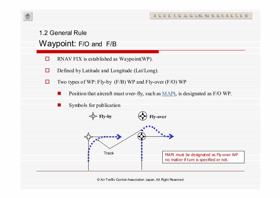
� RNAV FIX is established as Waypoint(WP).
� Defined by Latitude and Longitude (Lat/Long).
� Two types of WP: Fly-by (F/B) WP and Fly-over (F/O) WP
� Position that aircraft must over-fly, such as MAPt, is designated as F/O WP.
� Symbols for publication
1.2 General Rule
Waypoint: F/O and F/B
MAPt must be designated as Fly-over WP
no matter if turn is specified or not.
A C D E F G I1 I2 L M1 M2 N O P R S T V WA C D E F G I1 I2 L M1 M2 N O P R S T V W
Fly-overFly-by
Track
© Air Traffic Control Association Japan, All Right Reserved
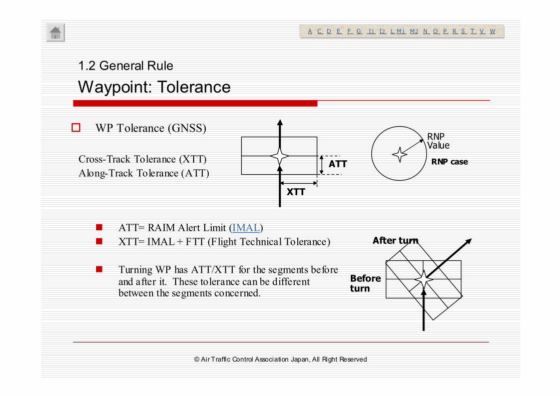
� WP Tolerance (GNSS)
Cross-Track Tolerance (XTT)
Along-Track Tolerance (ATT)
� ATT= RAIM Alert Limit (IMAL)
� XTT= IMAL + FTT (Flight Technical Tolerance)
� Turning WP has ATT/XTT for the segments before and after it. These tolerance can be different between the segments concerned.
After turn
Before turn
ATT
XTT
RNP Value
RNP case
1.2 General Rule
Waypoint: Tolerance
A C D E F G I1 I2 L M1 M2 N O P R S T V WA C D E F G I1 I2 L M1 M2 N O P R S T V W
© Air Traffic Control Association Japan, All Right Reserved
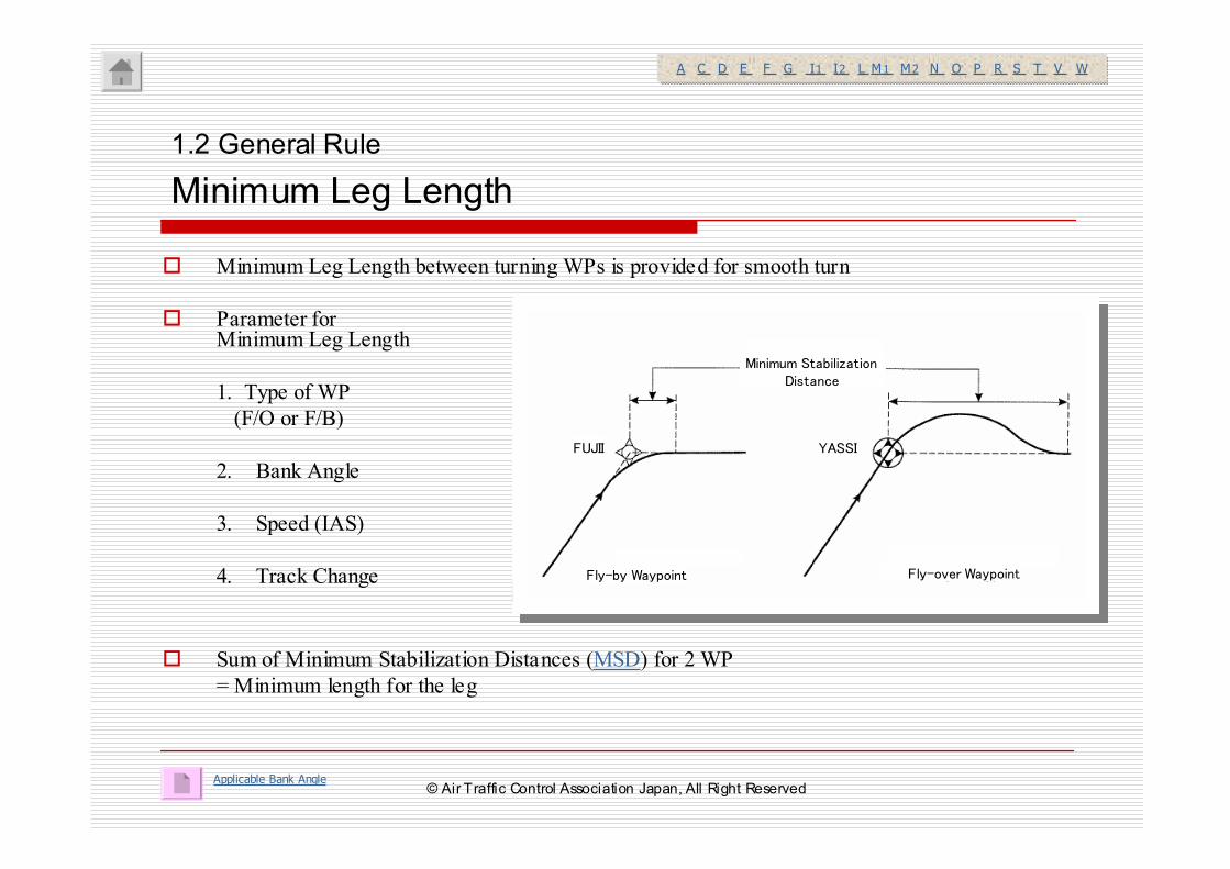
� Minimum Leg Length between turning WPs is provided for smooth turn
� Parameter for Minimum Leg Length
1. Type of WP
(F/O or F/B)
2. Bank Angle
3. Speed (IAS)
4. Track Change
� Sum of Minimum Stabilization Distances (MSD) for 2 WP
= Minimum length for the leg
1.2 General Rule
Minimum Leg Length
Applicable Bank Angle
A C D E F G I1 I2 L M1 M2 N O P R S T V WA C D E F G I1 I2 L M1 M2 N O P R S T V W
Minimum Stabilization Distance
Fly-by Waypoint Fly-over Waypoint
FUJII YASSI
© Air Traffic Control Association Japan, All Right Reserved
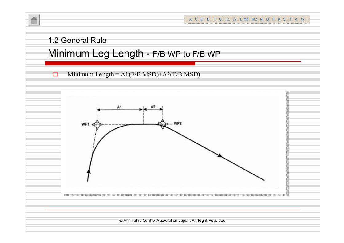
� Minimum Length = A1(F/B MSD)+A2(F/B MSD)
1.2 General Rule
Minimum Leg Length - F/B WP to F/B WP
A C D E F G I1 I2 L M1 M2 N O P R S T V WA C D E F G I1 I2 L M1 M2 N O P R S T V W
© Air Traffic Control Association Japan, All Right Reserved
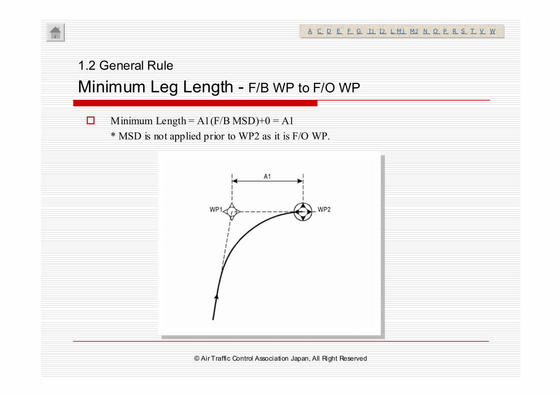
� Minimum Length = A1(F/B MSD)+0 = A1
* MSD is not applied prior to WP2 as it is F/O WP.
1.2 General Rule
Minimum Leg Length - F/B WP to F/O WP
A C D E F G I1 I2 L M1 M2 N O P R S T V WA C D E F G I1 I2 L M1 M2 N O P R S T V W
© Air Traffic Control Association Japan, All Right Reserved
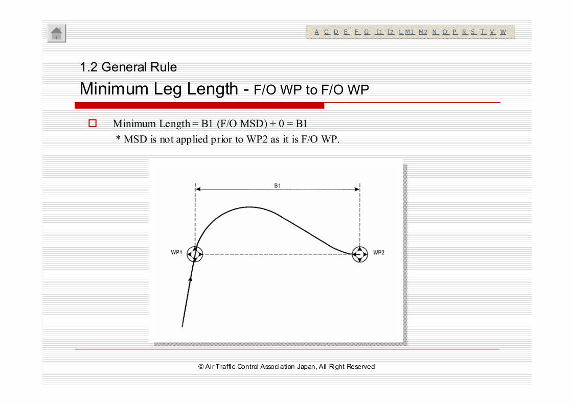
� Minimum Length = B1 (F/O MSD) + 0 = B1
* MSD is not applied prior to WP2 as it is F/O WP.
1.2 General Rule
Minimum Leg Length - F/O WP to F/O WP
A C D E F G I1 I2 L M1 M2 N O P R S T V WA C D E F G I1 I2 L M1 M2 N O P R S T V W
© Air Traffic Control Association Japan, All Right Reserved
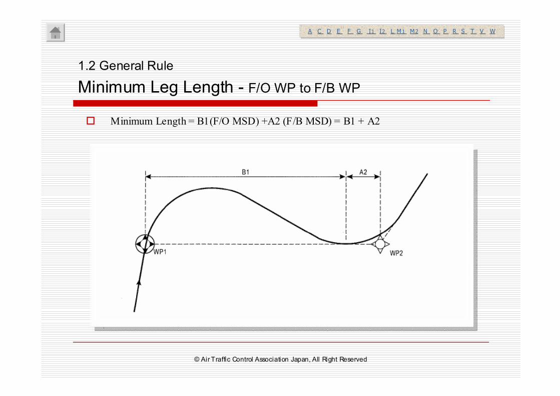
� Minimum Length = B1(F/O MSD) +A2 (F/B MSD) = B1 + A2
1.2 General Rule
Minimum Leg Length - F/O WP to F/B WP
A C D E F G I1 I2 L M1 M2 N O P R S T V WA C D E F G I1 I2 L M1 M2 N O P R S T V W
© Air Traffic Control Association Japan, All Right Reserved
1.2 General Rule
Turn Area
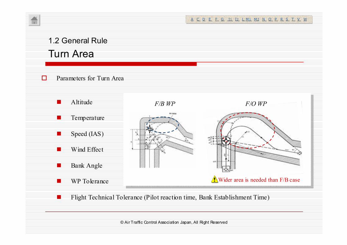
� Parameters for Turn Area
� Altitude
� Temperature
� Speed (IAS)
� Wind Effect
� Bank Angle
� WP Tolerance
� Flight Technical Tolerance (Pilot reaction time, Bank Establishment Time)
A C D E F G I1 I2 L M1 M2 N O P R S T V WA C D E F G I1 I2 L M1 M2 N O P R S T V W
F/B WP F/O WP
Wider area is needed than F/B case
© Air Traffic Control Association Japan, All Right Reserved
2. Enroute
� General
� Area / Obstacle Clearance
© Air Traffic Control Association Japan, All Right Reserved
� RNAV Route
� “VOR/DME”, “DME/DME” and “GNSS” as assumed as sensor.
* It is difficult to specify the sensor for Enroute RNAV.
2. Enroute
General
A C D E F G I1 I2 L M1 M2 N O P R S T V WA C D E F G I1 I2 L M1 M2 N O P R S T V W
Accuracy as “RNAV5” is required.
© Air Traffic Control Association Japan, All Right Reserved
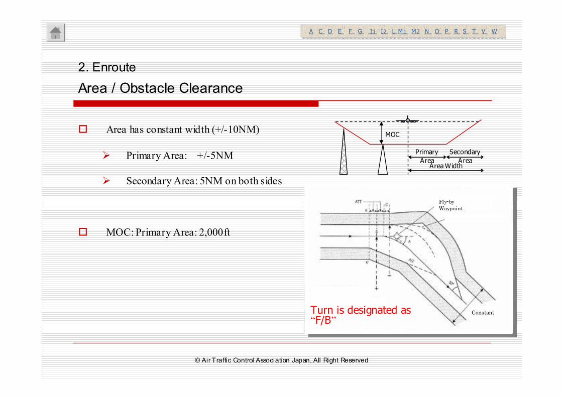
� Area has constant width (+/-10NM)
� Primary Area: +/-5NM
� Secondary Area: 5NM on both sides
� MOC: Primary Area: 2,000ft
Primary
Area
Secondary
AreaArea Width
MOC
2. Enroute
Area / Obstacle Clearance
A C D E F G I1 I2 L M1 M2 N O P R S T V WA C D E F G I1 I2 L M1 M2 N O P R S T V W
Fly-by
Waypoint
ConstantTurn is designated as “F/B”
© Air Traffic Control Association Japan, All Right Reserved
3.1 Departure
3.2 Arrival /Approach
3.3 T/Y Bar and TAA
3.4 APV / Baro-VNAV
3. Terminal
© Air Traffic Control Association Japan, All Right Reserved
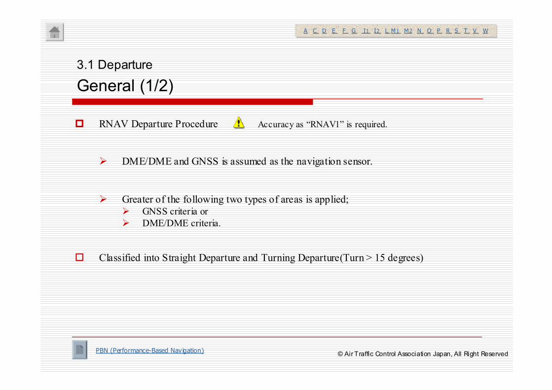
� RNAV Departure Procedure
� DME/DME and GNSS is assumed as the navigation sensor.
� Greater of the following two types of areas is applied; � GNSS criteria or
� DME/DME criteria.
� Classified into Straight Departure and Turning Departure(Turn > 15 degrees)
3.1 Departure
General (1/2)
A C D E F G I1 I2 L M1 M2 N O P R S T V WA C D E F G I1 I2 L M1 M2 N O P R S T V W
Accuracy as “RNAV1” is required.
PBN (Performance-Based Navigation)© Air Traffic Control Association Japan, All Right Reserved
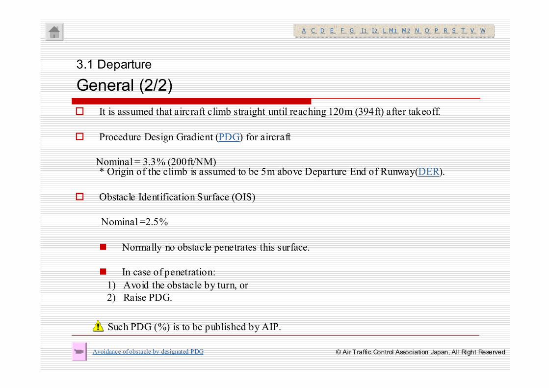
� It is assumed that aircraft climb straight until reaching 120m (394ft) after takeoff.
� Procedure Design Gradient (PDG) for aircraft
Nominal = 3.3% (200ft/NM)* Origin of the climb is assumed to be 5m above Departure End of Runway(DER).
� Obstacle Identification Surface (OIS)
Nominal =2.5%
� Normally no obstacle penetrates this surface.
� In case of penetration:
1) Avoid the obstacle by turn, or
2) Raise PDG.
3.1 Departure
General (2/2)
Avoidance of obstacle by designated PDG
A C D E F G I1 I2 L M1 M2 N O P R S T V WA C D E F G I1 I2 L M1 M2 N O P R S T V W
Such PDG (%) is to be published by AIP.
© Air Traffic Control Association Japan, All Right Reserved
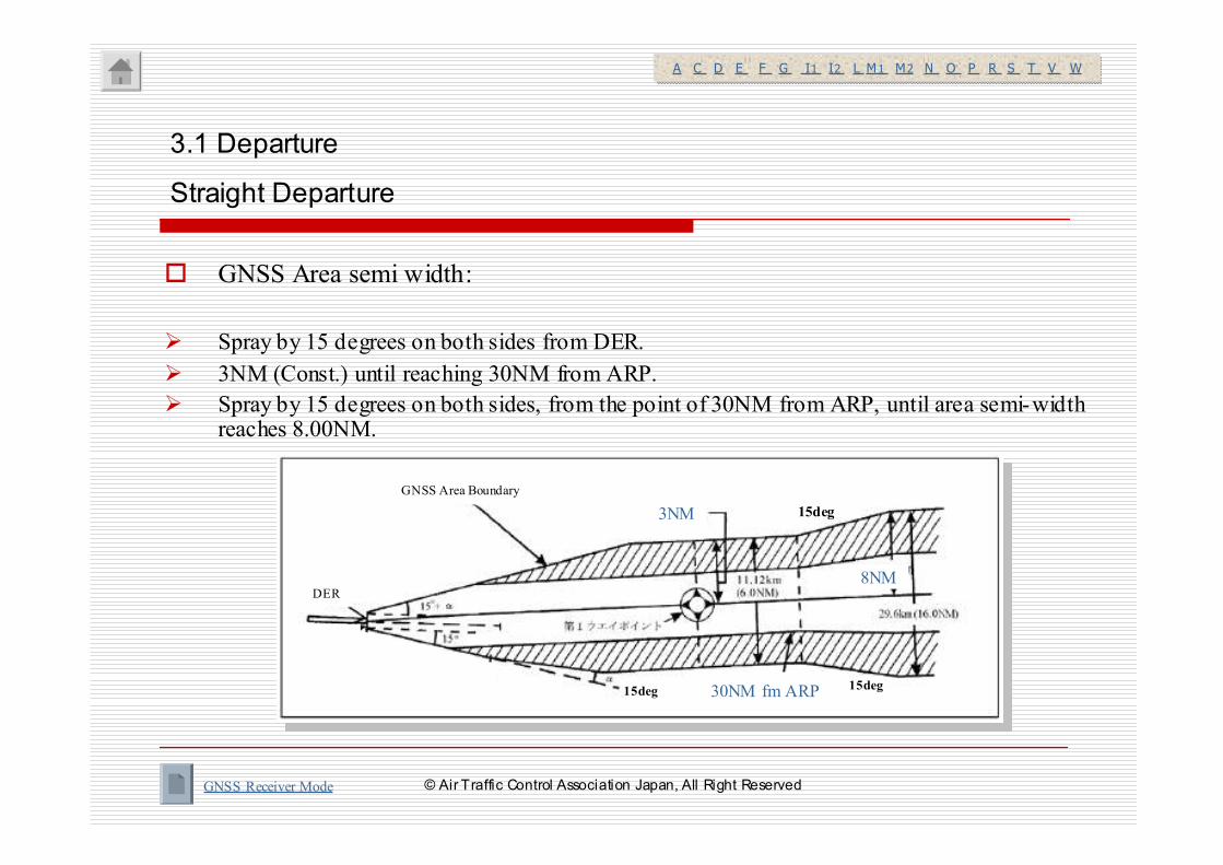
� GNSS Area semi width:
� Spray by 15 degrees on both sides from DER.
� 3NM (Const.) until reaching 30NM from ARP.
� Spray by 15 degrees on both sides, from the point of 30NM from ARP, until area semi-width reaches 8.00NM.
3.1 Departure
Straight Departure
GNSS Receiver Mode
A C D E F G I1 I2 L M1 M2 N O P R S T V WA C D E F G I1 I2 L M1 M2 N O P R S T V W
3NM
30NM fm ARP
GNSS Area Boundary
DER8NM
15deg
15deg15deg
© Air Traffic Control Association Japan, All Right Reserved
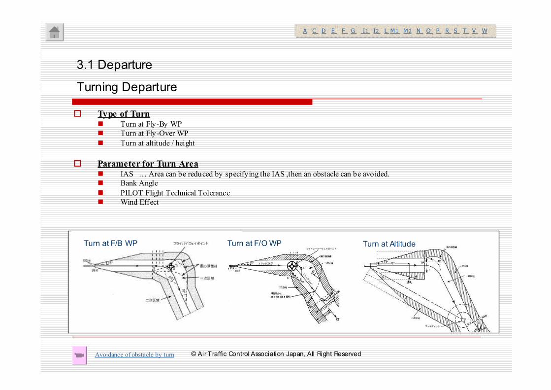
� Type of Turn� Turn at Fly-By WP
� Turn at Fly-Over WP
� Turn at altitude / height
� Parameter for Turn Area� IAS … Area can be reduced by specifying the IAS ,then an obstacle can be avoided.
� Bank Angle
� PILOT Flight Technical Tolerance
� Wind Effect
3.1 Departure
Turning Departure
Turn at F/B WP Turn at F/O WP Turn at Altitude
Avoidance of obstacle by turn
A C D E F G I1 I2 L M1 M2 N O P R S T V WA C D E F G I1 I2 L M1 M2 N O P R S T V W
© Air Traffic Control Association Japan, All Right Reserved
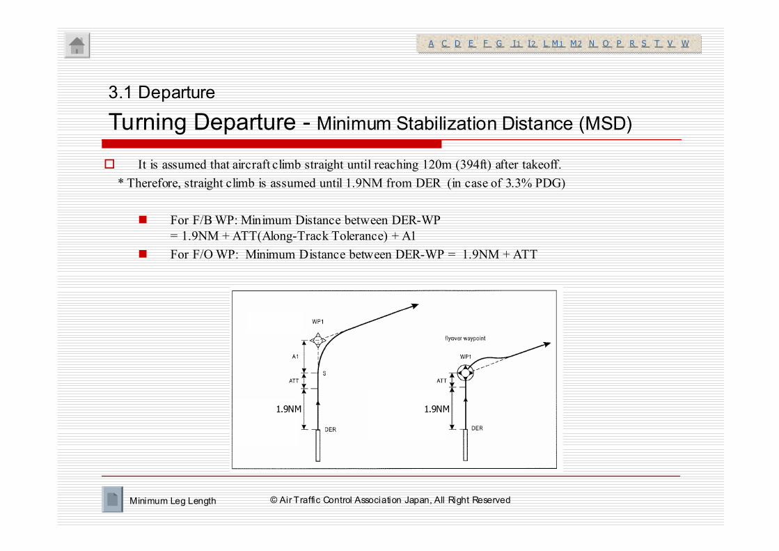
� It is assumed that aircraft climb straight until reaching 120m (394ft) after takeoff.
* Therefore, straight climb is assumed until 1.9NM from DER (in case of 3.3% PDG)
� For F/B WP: Minimum Distance between DER-WP
= 1.9NM + ATT(Along-Track Tolerance) + A1
� For F/O WP: Minimum Distance between DER-WP = 1.9NM + ATT
3.1 Departure
Turning Departure - Minimum Stabilization Distance (MSD)
Minimum Leg Length
A C D E F G I1 I2 L M1 M2 N O P R S T V WA C D E F G I1 I2 L M1 M2 N O P R S T V W
図3-2-1-6
1.9NM 1.9NM
© Air Traffic Control Association Japan, All Right Reserved

3.1 Departure
3.2 Arrival / Approach
3.3 T/Y Bar and TAA
3.4 APV / Baro-VNAV
3. Terminal
© Air Traffic Control Association Japan, All Right Reserved
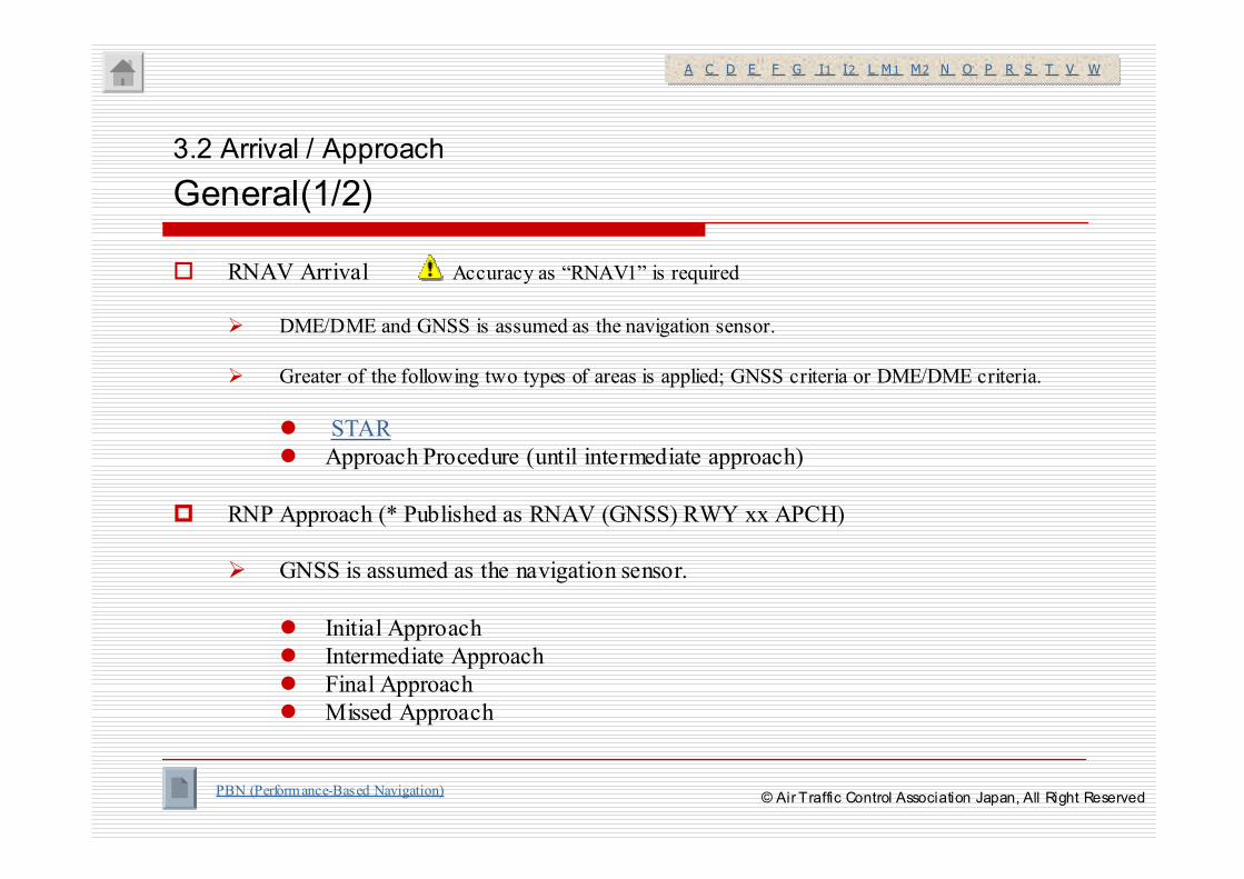
� RNAV Arrival
� DME/DME and GNSS is assumed as the navigation sensor.
� Greater of the following two types of areas is applied; GNSS criteria or DME/DME criteria.
� STAR
� Approach Procedure (until intermediate approach)
� RNP Approach (* Published as RNAV (GNSS) RWY xx APCH)
� GNSS is assumed as the navigation sensor.
� Initial Approach
� Intermediate Approach
� Final Approach
� Missed Approach
3.2 Arrival / Approach
General(1/2)
A C D E F G I1 I2 L M1 M2 N O P R S T V WA C D E F G I1 I2 L M1 M2 N O P R S T V W
Accuracy as “RNAV1” is required
PBN (Performance-Based Navigation)© Air Traffic Control Association Japan, All Right Reserved
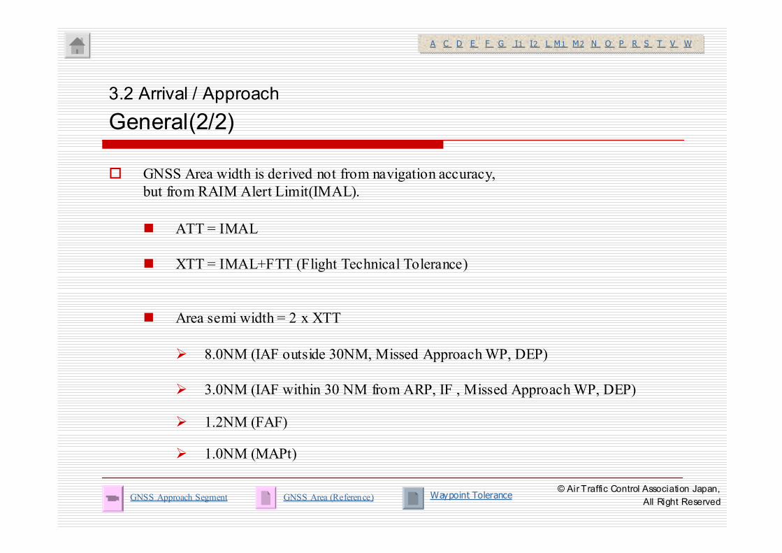
� GNSS Area width is derived not from navigation accuracy,
but from RAIM Alert Limit(IMAL).
� ATT = IMAL
� XTT = IMAL+FTT (Flight Technical Tolerance)
� Area semi width = 2 x XTT
� 8.0NM (IAF outside 30NM, Missed Approach WP, DEP)
� 3.0NM (IAF within 30 NM from ARP, IF , Missed Approach WP, DEP)
� 1.2NM (FAF)
� 1.0NM (MAPt)
3.2 Arrival / Approach
General(2/2)
GNSS Approach Segment
A C D E F G I1 I2 L M1 M2 N O P R S T V WA C D E F G I1 I2 L M1 M2 N O P R S T V W
GNSS Area (Reference) Waypoint Tolerance© Air Traffic Control Association Japan,
All Right Reserved
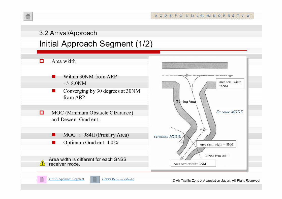
� Area width
� Within 30NM from ARP:
+/- 8.0NM
� Converging by 30 degrees at 30NM
from ARP
� MOC (Minimum Obstacle Clearance)
and Descent Gradient:
� MOC : 984ft (Primary Area)
� Optimum Gradient: 4.0%
3.2 Arrival/Approach
Initial Approach Segment (1/2)
GNSS Approach Segment
A C D E F G I1 I2 L M1 M2 N O P R S T V WA C D E F G I1 I2 L M1 M2 N O P R S T V W
Area width is different for each GNSSreceiver mode.
GNSS Receiver (Mode)
ARPより56km(30NM)ARPより56km(30NM)
Area semi-width= 3NM
Area semi-width = 8NM
30NM from ARP
Turning Area
Area semi width
=8NM
En route MODE
Terminal MODE
© Air Traffic Control Association Japan, All Right Reserved
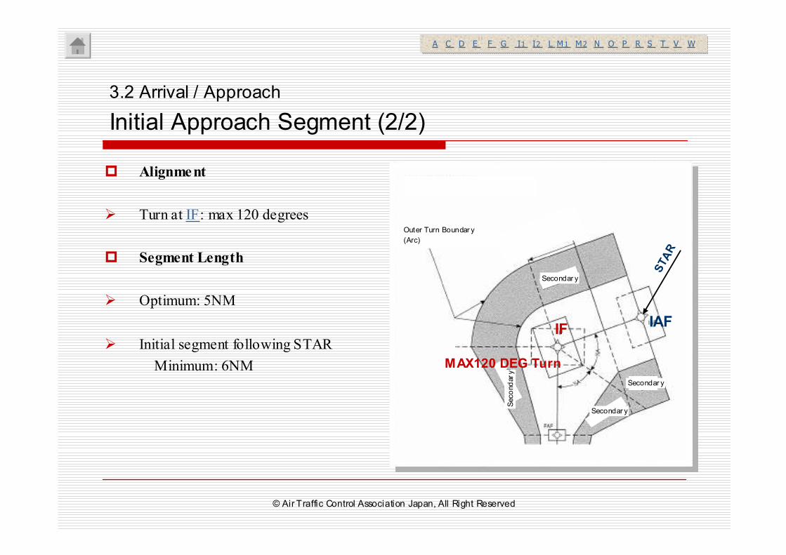
� Alignment
� Turn at IF: max 120 degrees
� Segment Length
� Optimum: 5NM
� Initial segment following STAR
Minimum: 6NM
3.2 Arrival / Approach
Initial Approach Segment (2/2)
A C D E F G I1 I2 L M1 M2 N O P R S T V WA C D E F G I1 I2 L M1 M2 N O P R S T V W
*初期セグメントと中間セグメントの分割―図
Ⅲ-3-2-5参照
外側旋回境界線(円形アーク)
二次区域
二次区域
二次
区域
二次区域
d1(最も手前のTP)図Ⅲ
-3-2-5より
*初期セグメントと中間セグメントの分割―図
Ⅲ-3-2-5参照
外側旋回境界線(円形アーク)
二次区域
二次区域
二次
区域
二次区域
d1(最も手前のTP)図Ⅲ
-3-2-5より
MAX120 DEG Turn
IFIAF
STAR
Outer Turn Boundar y
(Arc)
Secondar y
Secondar y
Secondar y
Secondary
© Air Traffic Control Association Japan, All Right Reserved
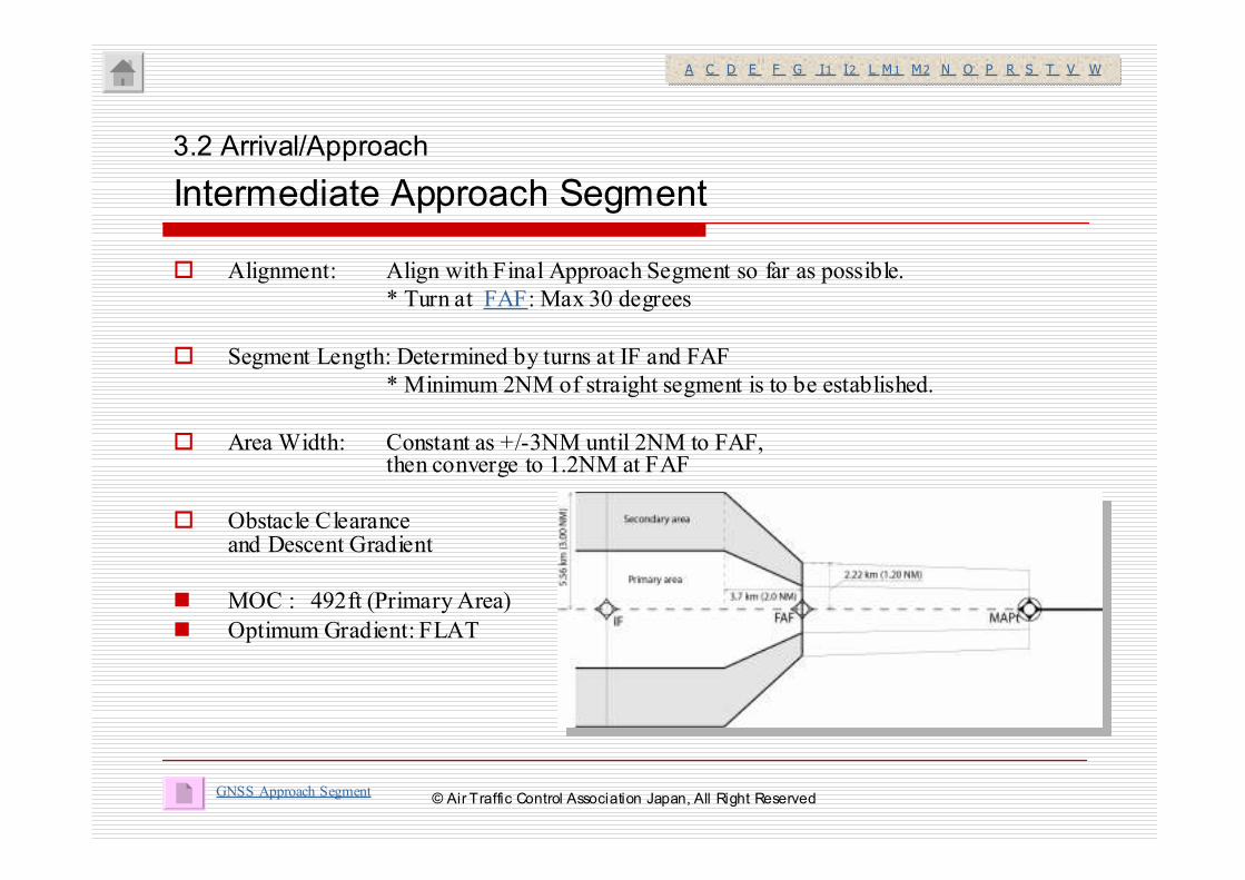
� Alignment: Align with Final Approach Segment so far as possible.
* Turn at FAF: Max 30 degrees
� Segment Length: Determined by turns at IF and FAF
* Minimum 2NM of straight segment is to be established.
� Area Width: Constant as +/-3NM until 2NM to FAF, then converge to 1.2NM at FAF
� Obstacle Clearanceand Descent Gradient
� MOC : 492ft (Primary Area)
� Optimum Gradient: FLAT
3.2 Arrival/Approach
Intermediate Approach Segment
GNSS Approach Segment
A C D E F G I1 I2 L M1 M2 N O P R S T V WA C D E F G I1 I2 L M1 M2 N O P R S T V W
© Air Traffic Control Association Japan, All Right Reserved
� Alignment
� In principle, align with runway centerline.
� Segment Length
� Optimum Length: 5NM
� Area
� Secondary Area is applied.
� Primary Area/Secondary Area widths at FAF and MAPt are combined.
� Obstacle Clearance and Descent Gradient
� MOC : 246ft (Primary Area)
� Optimum Gradient: 5.2% (3degrees)
3.2 Arrival/Approach
Final Approach Segment
GNSS Approach Segment
A C D E F G I1 I2 L M1 M2 N O P R S T V WA C D E F G I1 I2 L M1 M2 N O P R S T V W
© Air Traffic Control Association Japan, All Right Reserved
� MAPt is established as Fly-over WP no matter if turn is specified at MAPt or not.
� Rule for “Minimum Leg Length” is applied to Distance
from MAPt to MATF or MAHF ( F/O to F/O).
3.2 Arrival/Approach
Missed Approach Segment (1/2)
A C D E F G I1 I2 L M1 M2 N O P R S T V WA C D E F G I1 I2 L M1 M2 N O P R S T V W
Minimum Leg Length(F/O to F/O)© Air Traffic Control Association Japan, All Right Reserved
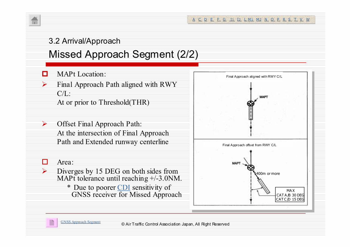
� MAPt Location:
� Final Approach Path aligned with RWY
C/L:
At or prior to Threshold(THR)
� Offset Final Approach Path:
At the intersection of Final Approach
Path and Extended runway centerline
� Area:
� Diverges by 15 DEG on both sides from MAPt tolerance until reaching +/-3.0NM.
* Due to poorer CDI sensitivity of GNSS receiver for Missed Approach
3.2 Arrival/Approach
Missed Approach Segment (2/2)
A C D E F G I1 I2 L M1 M2 N O P R S T V WA C D E F G I1 I2 L M1 M2 N O P R S T V W
GNSS Approach Segment
滑走路にアラインした最終進入
滑走路中心線よりオフセットされた最終進入
第Ⅰ部第4編第5章
に従ったアライメント
滑走路にアラインした最終進入
滑走路中心線よりオフセットされた最終進入
第Ⅰ部第4編第5章
に従ったアライメント
MAX
CAT A /B 30 DEGCAT C /D 15 DEG
1400m or more
Final Approach aligned with RWY C/L
Final Approach offset from RWY C/L
© Air Traffic Control Association Japan, All Right Reserved
3.1 Departure
3.2 Arrival / Approach
3.3 T/Y Bar and TAA
3.4 APV / Baro-VNAV
3. Terminal
© Air Traffic Control Association Japan, All Right Reserved
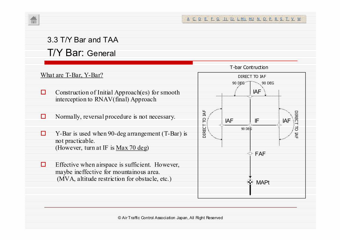
What are T-Bar, Y-Bar?
� Construction of Initial Approach(es) for smooth interception to RNAV(final) Approach
� Normally, reversal procedure is not necessary.
� Y-Bar is used when 90-deg arrangement (T-Bar) is not practicable.(However, turn at IF is Max 70 deg)
� Effective when airspace is sufficient. However, maybe ineffective for mountainous area.(MVA, altitude restriction for obstacle, etc.)
3.3 T/Y Bar and TAA
T/Y Bar: General
T-bar Contruction
IF IAFIAF
IAF
FAF
MAPt
90 DEG90 DEG
90 DEG
DIRECT TO IAF
DIRECT TO IAF D
IRECT TO IA
F
A C D E F G I1 I2 L M1 M2 N O P R S T V WA C D E F G I1 I2 L M1 M2 N O P R S T V W
© Air Traffic Control Association Japan, All Right Reserved
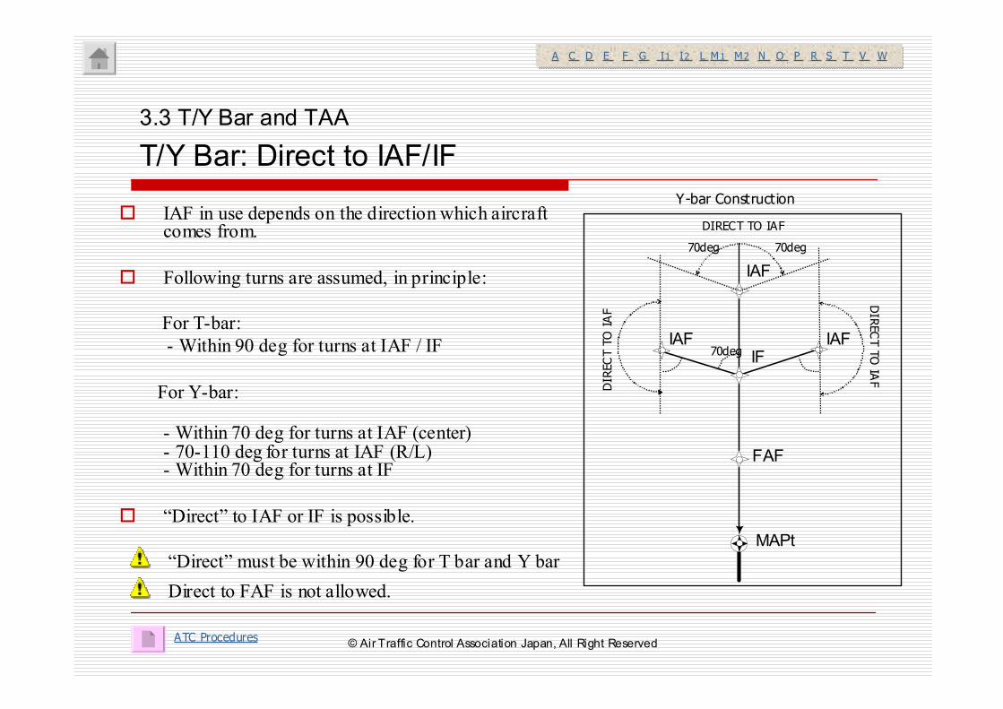
� IAF in use depends on the direction which aircraft comes from.
� Following turns are assumed, in principle:
For T-bar:
- Within 90 deg for turns at IAF / IF
For Y-bar:
- Within 70 deg for turns at IAF (center)- 70-110 deg for turns at IAF (R/L)- Within 70 deg for turns at IF
� “Direct” to IAF or IF is possible.
3.3 T/Y Bar and TAA
T/Y Bar: Direct to IAF/IF
Y-bar Construction
ATC Procedures
IFIAFIAF
IAF
FAF
MAPt
70deg70deg
70deg
DIRECT TO IAF
DIRECT TO IAF
DIRECT TO IA
F
A C D E F G I1 I2 L M1 M2 N O P R S T V WA C D E F G I1 I2 L M1 M2 N O P R S T V W
“Direct” must be within 90 deg for T bar and Y bar
Direct to FAF is not allowed.
© Air Traffic Control Association Japan, All Right Reserved
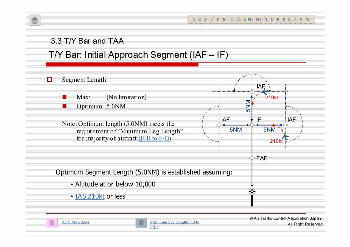
� Segment Length:
� Max: (No limitation)
� Optimum: 5.0NM
Note: Optimum length (5.0NM) meets the requirement of “Minimum Leg Length”for majority of aircraft.(F/B to F/B)
3.3 T/Y Bar and TAA
T/Y Bar: Initial Approach Segment (IAF – IF)
ATC Procedures
IF IAFIAF
IAF
5NM5NM
5NM
210kt
210kt
Optimum Segment Length (5.0NM) is established assuming:
• Altitude at or below 10,000
• IAS 210kt or less
A C D E F G I1 I2 L M1 M2 N O P R S T V WA C D E F G I1 I2 L M1 M2 N O P R S T V W
Minimum Leg Length(F/B to
F/B)
FAF
© Air Traffic Control Association Japan,
All Right Reserved
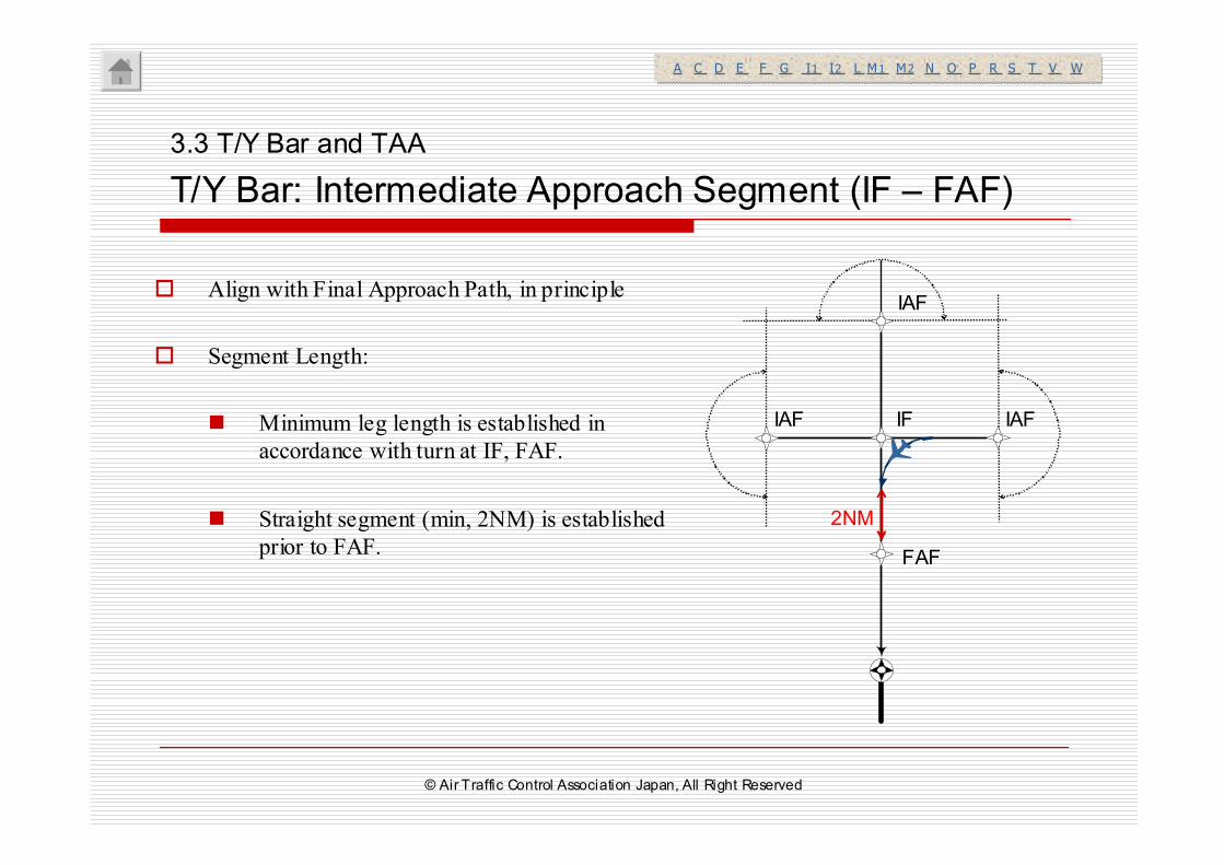
� Align with Final Approach Path, in principle
� Segment Length:
� Minimum leg length is established in
accordance with turn at IF, FAF.
� Straight segment (min, 2NM) is established
prior to FAF.
3.3 T/Y Bar and TAA
T/Y Bar: Intermediate Approach Segment (IF – FAF)
IF IAFIAF
IAF
FAF
2NM
A C D E F G I1 I2 L M1 M2 N O P R S T V WA C D E F G I1 I2 L M1 M2 N O P R S T V W
© Air Traffic Control Association Japan, All Right Reserved
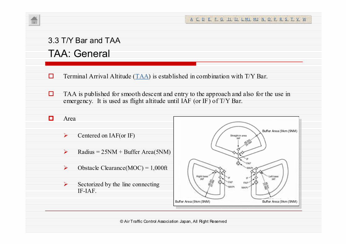
� Terminal Arrival Altitude (TAA) is established in combination with T/Y Bar.
� TAA is published for smooth descent and entry to the approach and also for the use in emergency. It is used as flight altitude until IAF (or IF) of T/Y Bar.
� Area
� Centered on IAF(or IF)
� Radius = 25NM + Buffer Area(5NM)
� Obstacle Clearance(MOC) = 1,000ft
� Sectorized by the line connecting IF-IAF.
3.3 T/Y Bar and TAA
TAA: General
A C D E F G I1 I2 L M1 M2 N O P R S T V WA C D E F G I1 I2 L M1 M2 N O P R S T V W
緩衝区域9km(5NM)
緩衝区域9km(5NM)緩衝区域9km(5NM)
緩衝区域9km(5NM)
緩衝区域9km(5NM)緩衝区域9km(5NM)Buffer Area (9km (5NM) Buffer Area (9km (5NM)
Buffer Area (9km (5NM)
© Air Traffic Control Association Japan, All Right Reserved
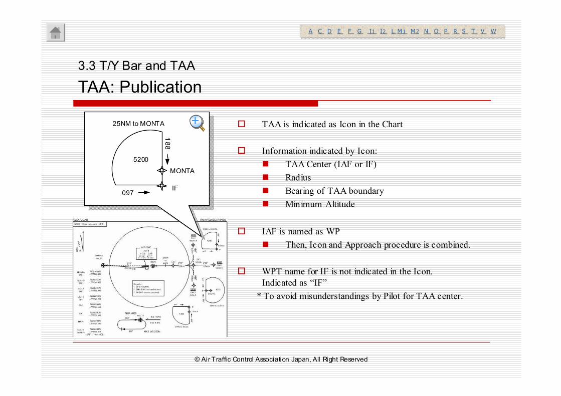
� TAA is indicated as Icon in the Chart
� Information indicated by Icon:
� TAA Center (IAF or IF)
� Radius
� Bearing of TAA boundary
� Minimum Altitude
� IAF is named as WP
� Then, Icon and Approach procedure is combined.
� WPT name for IF is not indicated in the Icon.
Indicated as “IF”
* To avoid misunderstandings by Pilot for TAA center.
3.3 T/Y Bar and TAA
TAA: Publication
MONTA
188
097
5200
IF
25NM to MONTA
A C D E F G I1 I2 L M1 M2 N O P R S T V WA C D E F G I1 I2 L M1 M2 N O P R S T V W
++++++++
© Air Traffic Control Association Japan, All Right Reserved
3.1 Departure
3.2 Arrival / Approach
3.3 T/Y Bar and TAA
3.4 APV / Baro-VNAV
3. Terminal
© Air Traffic Control Association Japan, All Right Reserved
� APV: Approach Procedure with Vertical Guidance
Utilize vertical/lateral guidance, but does not meet the requirements for Precision Approach.Followings fall into APV.
� APV/Baro-VNAV : 3 deg vertical path is generated by pressure altimeter and FMS
� APV-I/ II: APV using SBAS
� DA established instead of MDA.
� FAF and MAPt for LNAVApproach is applied.APV/Baro-VNAV is regarded as another mode of operation of RNAV Approach(RNP APCH), and published in the same approach chart.
� VNAV MINIMA is also published.
3.4 APV / Baro VNAV
General(1/3)
A C D E F G I1 I2 L M1 M2 N O P R S T V WA C D E F G I1 I2 L M1 M2 N O P R S T V W
VNAV is used in combination with RNAV (RNP) Approach Procedure.
© Air Traffic Control Association Japan, All Right Reserved
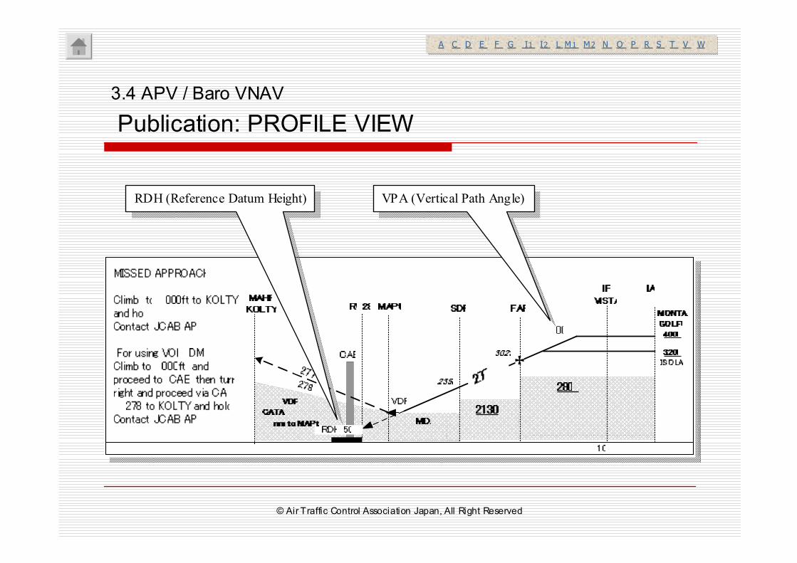
� Published VPA(Vertical Path Angle) : 3deg (Max 3.5 deg)
� THR Crossing Height (RDH: Reference Datum Height): 50ft
� Final Approach Course must align with runway centerline.
3.4 APV / Baro VNAV
General(2/3)
A C D E F G I1 I2 L M1 M2 N O P R S T V WA C D E F G I1 I2 L M1 M2 N O P R S T V W
VNAV not permitted for offset approach
© Air Traffic Control Association Japan, All Right Reserved
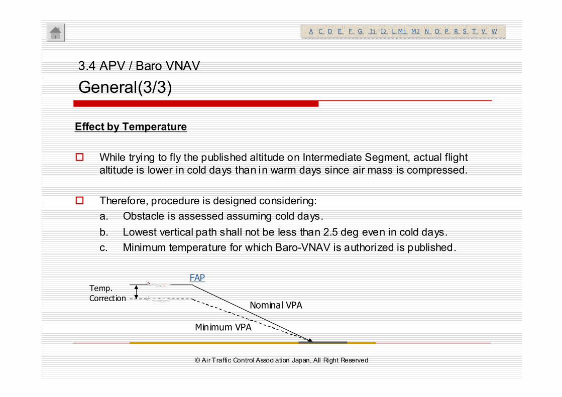
Effect by Temperature
� While trying to fly the published altitude on Intermediate Segment, actual flight
altitude is lower in cold days than in warm days since air mass is compressed.
� Therefore, procedure is designed considering:
a. Obstacle is assessed assuming cold days.
b. Lowest vertical path shall not be less than 2.5 deg even in cold days.
c. Minimum temperature for which Baro-VNAV is authorized is published.
3.4 APV / Baro VNAV
General(3/3)
FAP
Nominal VPA
Minimum VPA
Temp.
Correction
A C D E F G I1 I2 L M1 M2 N O P R S T V WA C D E F G I1 I2 L M1 M2 N O P R S T V W
AT CA J ●AT CA J ●
AT CA J ●AT CA J ●
© Air Traffic Control Association Japan, All Right Reserved
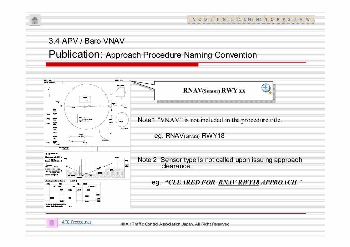
Note1 “VNAV” is not included in the procedure title.
eg. RNAV(GNSS) RWY18
Note 2 Sensor type is not called upon issuing approachclearance.
eg. “CLEARED FOR RNAV RWY18 APPROACH.”
3.4 APV / Baro VNAV
Publication: Approach Procedure Naming Convention
ATC Procedures
RNAV(Sensor) RWY xx
A C D E F G I1 I2 L M1 M2 N O P R S T V WA C D E F G I1 I2 L M1 M2 N O P R S T V W
++++++++
© Air Traffic Control Association Japan, All Right Reserved
3.4 APV / Baro VNAV
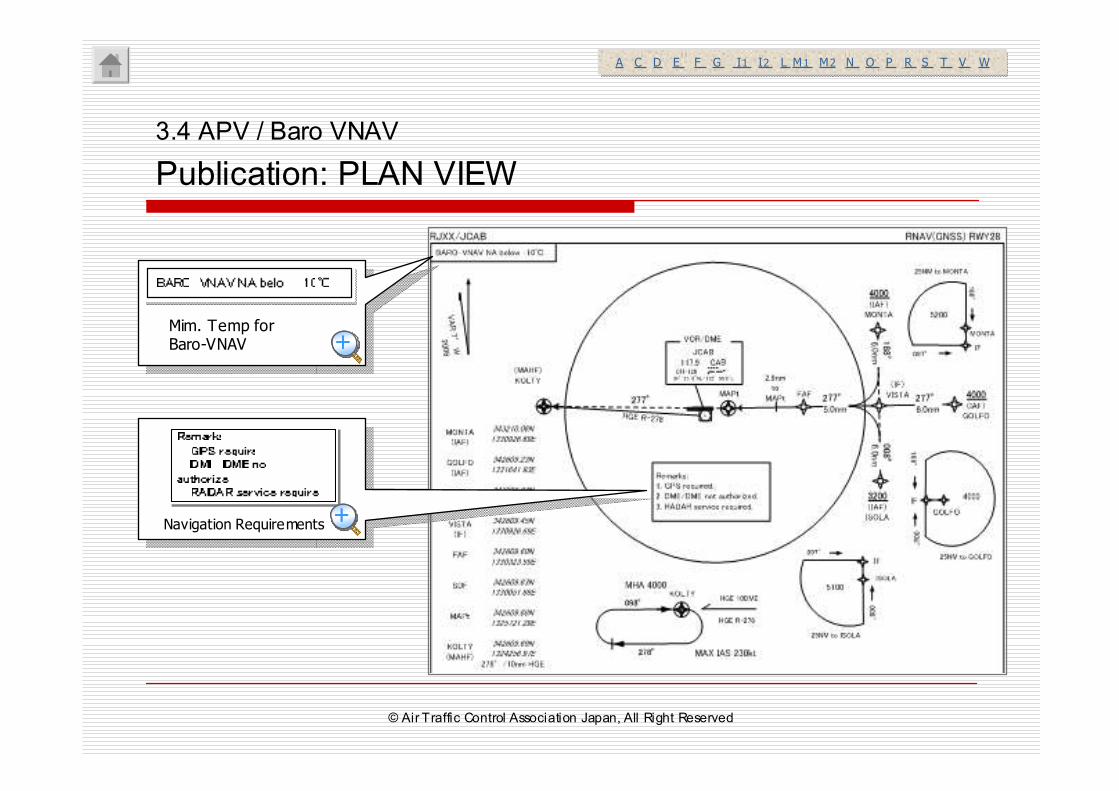
Publication: PLAN VIEW
Navigation Requirements
Mim. Temp for Baro-VNAV
A C D E F G I1 I2 L M1 M2 N O P R S T V WA C D E F G I1 I2 L M1 M2 N O P R S T V W
++++++++
++++++++
© Air Traffic Control Association Japan, All Right Reserved
3.4 APV / Baro VNAV
Publication: PROFILE VIEW
VPA (Vertical Path Angle)VPA (Vertical Path Angle)RDH (Reference Datum Height)RDH (Reference Datum Height)
A C D E F G I1 I2 L M1 M2 N O P R S T V WA C D E F G I1 I2 L M1 M2 N O P R S T V W
© Air Traffic Control Association Japan, All Right Reserved
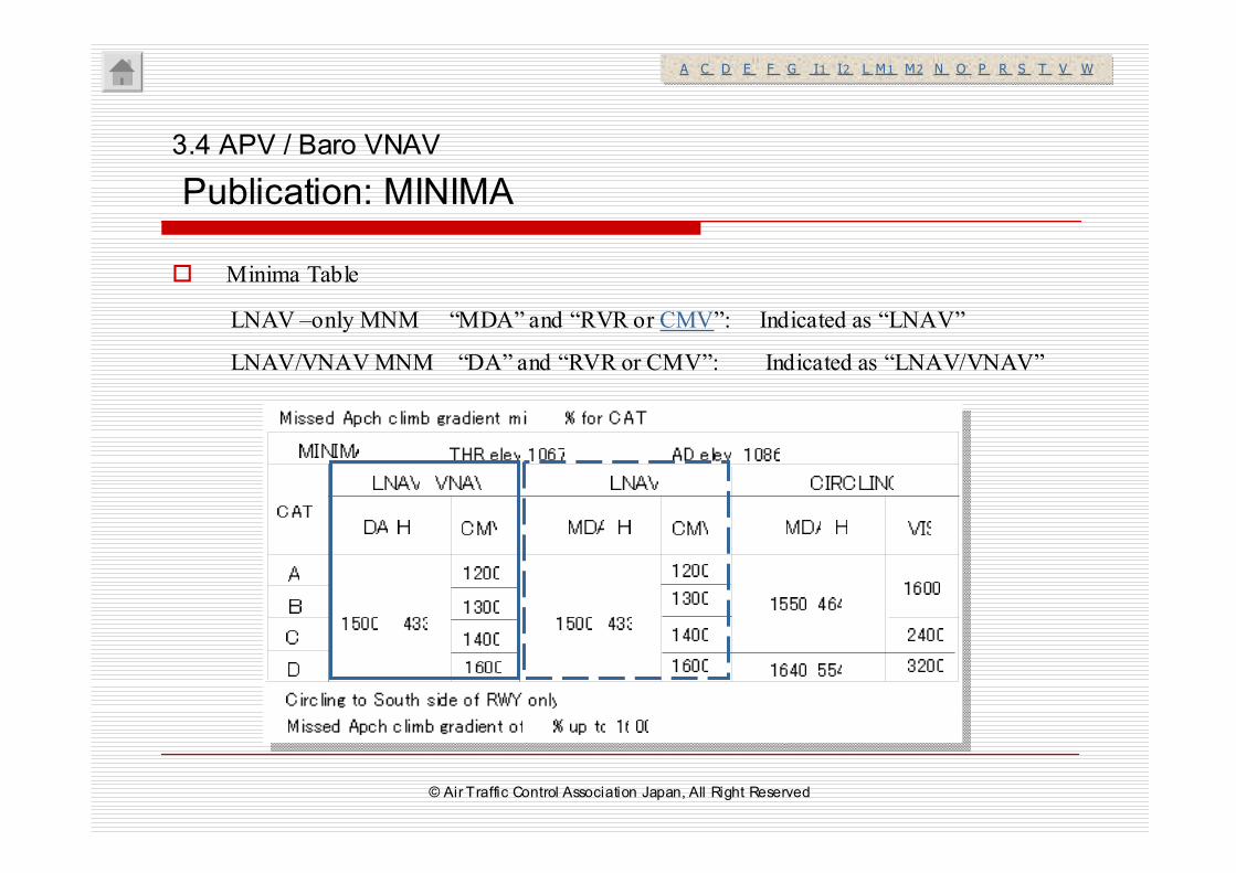
� Minima Table
3.4 APV / Baro VNAV
Publication: MINIMA
A C D E F G I1 I2 L M1 M2 N O P R S T V WA C D E F G I1 I2 L M1 M2 N O P R S T V W
LNAV –only MNM “MDA” and “RVR or CMV”: Indicated as “LNAV”
LNAV/VNAV MNM “DA” and “RVR or CMV”: Indicated as “LNAV/VNAV”
© Air Traffic Control Association Japan, All Right Reserved
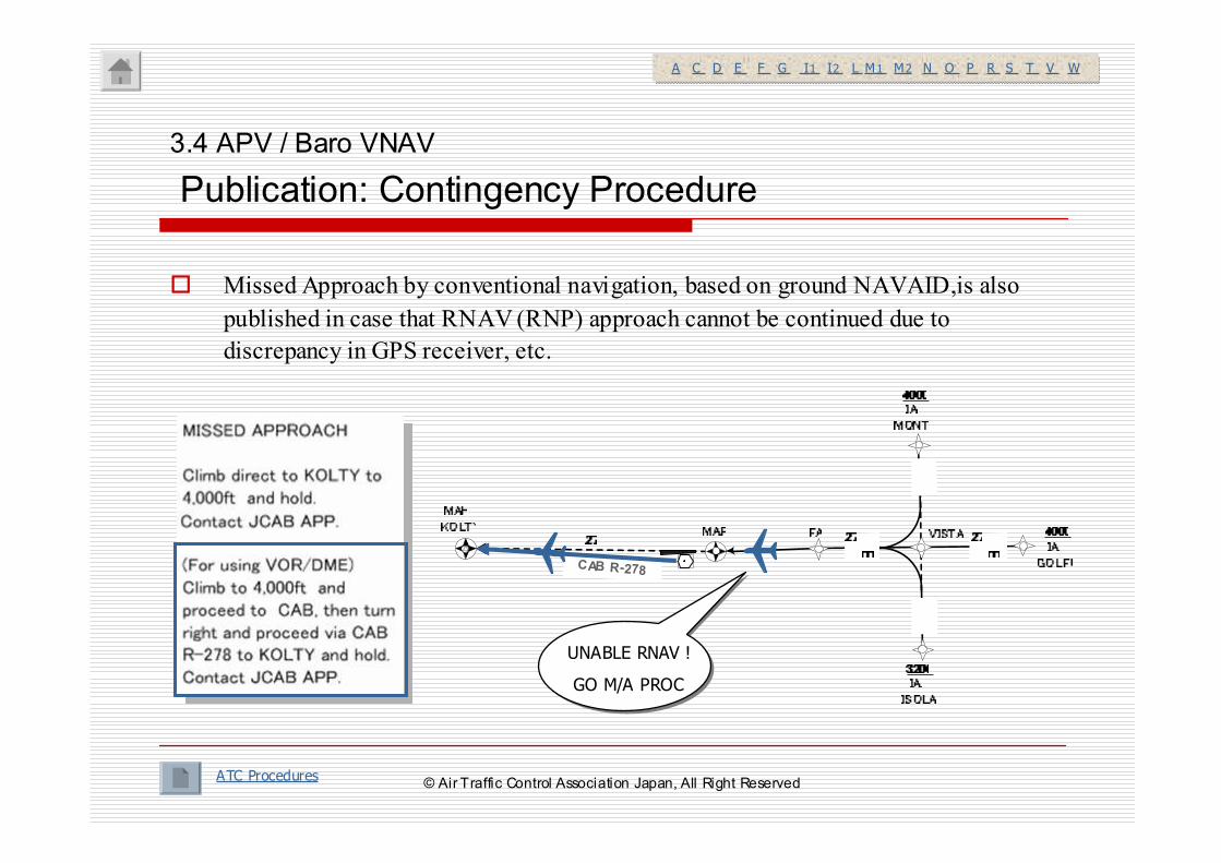
3.4 APV / Baro VNAV
Publication: Contingency Procedure
ATC Procedures
UNABLE RNAV !
GO M/A PROC
CAB R-278
A C D E F G I1 I2 L M1 M2 N O P R S T V WA C D E F G I1 I2 L M1 M2 N O P R S T V W
� Missed Approach by conventional navigation, based on ground NAVAID,is also
published in case that RNAV (RNP) approach cannot be continued due to
discrepancy in GPS receiver, etc.
© Air Traffic Control Association Japan, All Right Reserved
4. Holding
� General
� Type
� Entry Procedure
© Air Traffic Control Association Japan, All Right Reserved
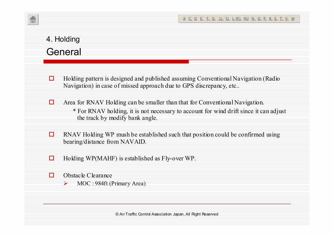
� Holding pattern is designed and published assuming Conventional Navigation (Radio Navigation) in case of missed approach due to GPS discrepancy, etc..
� Area for RNAV Holding can be smaller than that for Conventional Navigation.
* For RNAV holding, it is not necessary to account for wind drift since it can adjust the track by modify bank angle.
� RNAV Holding WP mush be established such that position could be confirmed using bearing/distance from NAVAID.
� Holding WP(MAHF) is established as Fly-over WP.
� Obstacle Clearance
� MOC : 984ft (Primary Area)
4. Holding
General
A C D E F G I1 I2 L M1 M2 N O P R S T V WA C D E F G I1 I2 L M1 M2 N O P R S T V W
© Air Traffic Control Association Japan, All Right Reserved
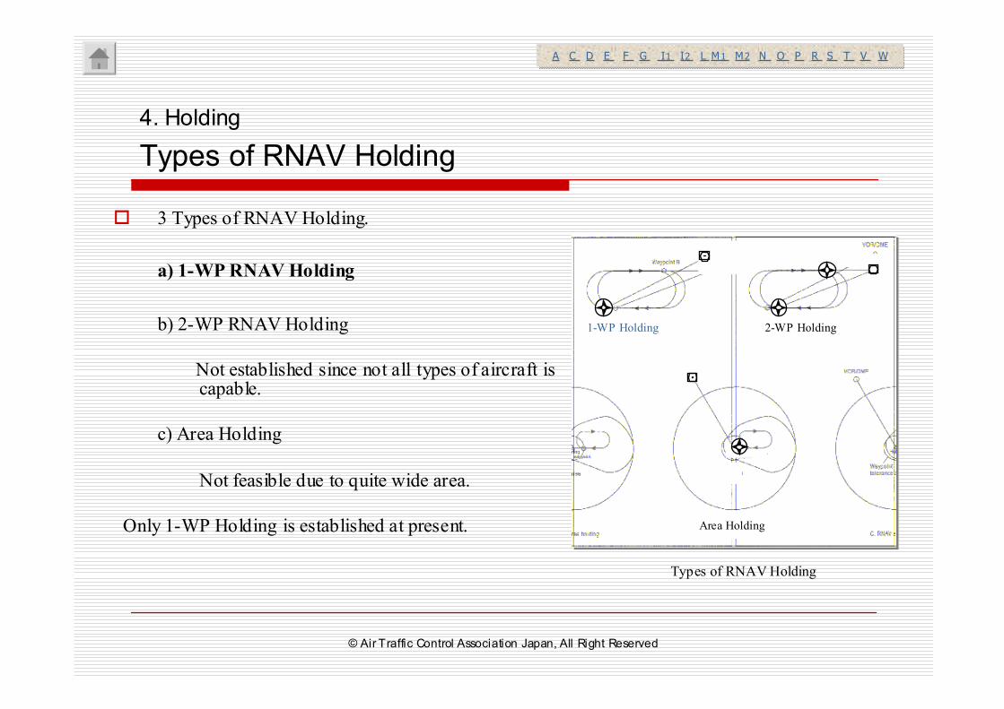
� 3 Types of RNAV Holding.
a) 1-WP RNAV Holding
b) 2-WP RNAV Holding
Not established since not all types of aircraft is capable.
c) Area Holding
Not feasible due to quite wide area.
Only 1-WP Holding is established at present.
ウェイポイント
A. ウェイポイント1つのRNAV待機
ウェイポイントB
ウェイポイント
B. ウェイポイント2つのRNAV待機
ウェ イ ポイ ント
許容誤差区域
C. RNAV区域待機
待機ウェ イポイ ン ト
Types of RNAV Holding
4. Holding
Types of RNAV Holding
A C D E F G I1 I2 L M1 M2 N O P R S T V WA C D E F G I1 I2 L M1 M2 N O P R S T V W
1-WP Holding 2-WP Holding
Area Holding
© Air Traffic Control Association Japan, All Right Reserved
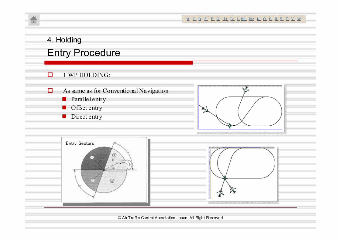
� 1 WP HOLDING:
� As same as for Conventional Navigation
� Parallel entry
� Offset entry
� Direct entry
Entry Sectors
4. Holding
Entry Procedure
A C D E F G I1 I2 L M1 M2 N O P R S T V WA C D E F G I1 I2 L M1 M2 N O P R S T V W
© Air Traffic Control Association Japan, All Right Reserved
II. II. RNAV ATC ProcedureRNAV ATC Proceduress
I. RNAVGeneral© Air Traffic Control Association Japan, All Right Reserved
RNAV Training for ATC - Part II
6. RNAVApproach ATC Procedures
5. Terminal/Enroute ATC Procedures
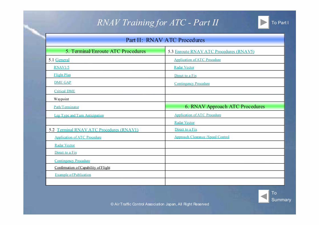
Part II: RNAV ATC Procedures
To Part I
5.3 Enroute RNAV ATC Procedures (RNAV5)
To
Summary
5.1 General
RNAV1/5
Flight Plan
DME GAP
Critical DME
Waypoint
Path/Terminator
Leg Type and Turn Anticipation
5.2 Terminal RNAV ATC Procedures (RNAV1)
Application of ATC Procedure
Radar Vector
Direct to a Fix
Contingency Procedure
Confirmation of Capability of Flight
Application of ATC Procedure
Radar Vector
Direct to a Fix
Contingency Procedure
Application of ATC Procedure
Radar Vector
Direct to a Fix
Approach Clearance /Speed Control
Example of Publication
© Air Traffic Control Association Japan, All Right Reserved
5. Terminal/Enroute ATC Procedures
5.1 General
5.2 Terminal RNAV ATC
Procedures(RNAV1)
5.3 Enroute RNAV ATC Procedures(RNAV5)
Summary
© Air Traffic Control Association Japan, All Right Reserved
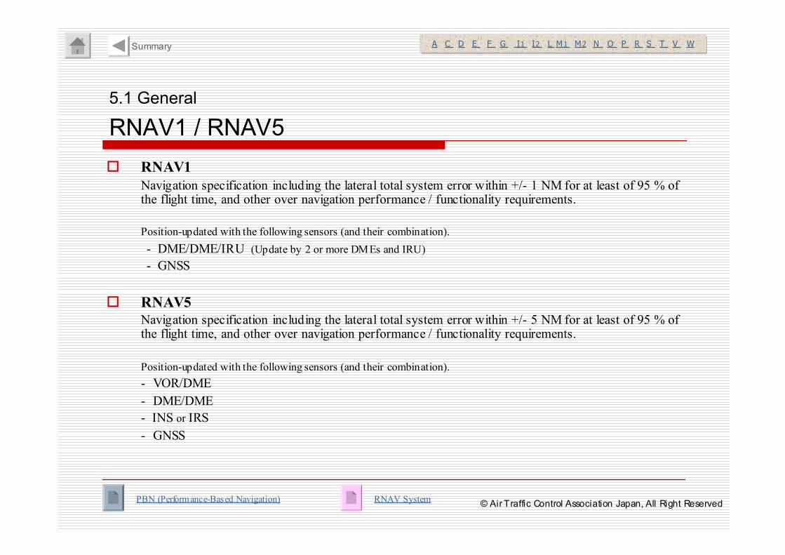
� RNAV1
Navigation specification including the lateral total system error within +/- 1 NM for at least of 95 % of the flight time, and other over navigation performance / functionality requirements.
Position-updated with the following sensors (and their combination).
- DME/DME/IRU (Update by 2 or more DMEs and IRU)
- GNSS
� RNAV5
Navigation specification including the lateral total system error within +/- 5 NM for at least of 95 % of the flight time, and other over navigation performance / functionality requirements.
Position-updated with the following sensors (and their combination).
- VOR/DME
- DME/DME
- INS or IRS
- GNSS
5.1 General
RNAV1 / RNAV5
PBN (Performance-Based Navigation)
A C D E F G I1 I2 L M1 M2 N O P R S T V WA C D E F G I1 I2 L M1 M2 N O P R S T V WSummary
RNAV System© Air Traffic Control Association Japan, All Right Reserved
5.1 General
Flight Plan (1/6): RNAV1 Requirements
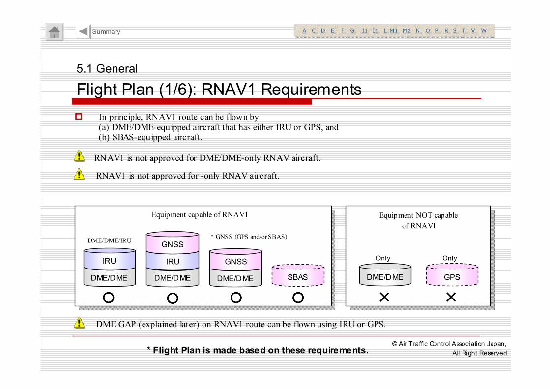
� In principle, RNAV1 route can be flown by
(a) DME/DME-equipped aircraft that has either IRU or GPS, and (b) SBAS-equipped aircraft.
A C D E F G I1 I2 L M1 M2 N O P R S T V WA C D E F G I1 I2 L M1 M2 N O P R S T V WSummary
RNAV1 is not approved for DME/DME-only RNAV aircraft.
RNAV1 is not approved for -only RNAV aircraft.
DME GAP (explained later) on RNAV1 route can be flown using IRU or GPS.
* Flight Plan is made based on these requirements.
DME/DME
IRU
○○○○
DME/DME
IRU
GNSS
○○○○
DME/DME
GNSS
○○○○
DME/DME
×
GPS
×
DME/DME/IRU
Equipment capable of RNAV1 Equipment NOT capable
of RNAV1
Only Only
SBAS
○○○○
* GNSS (GPS and/or SBAS)
© Air Traffic Control Association Japan,
All Right Reserved
5.1 General
Flight Plan(2/6): RNAV5 Requirements
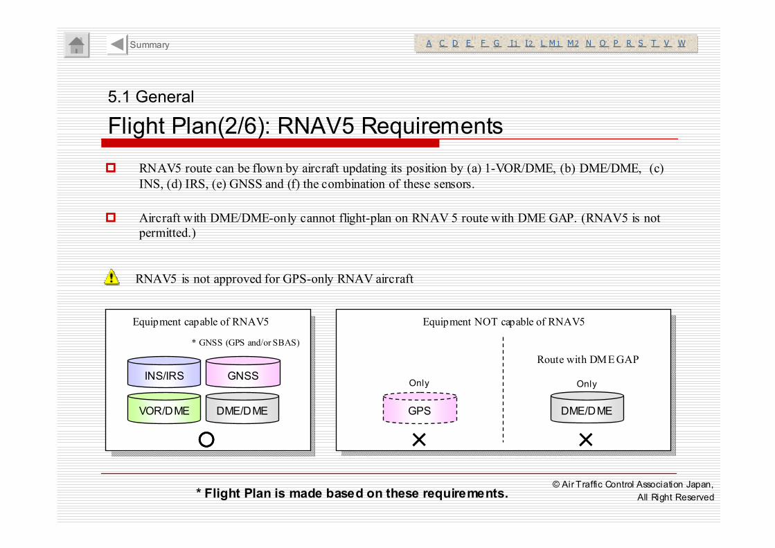
� RNAV5 route can be flown by aircraft updating its position by (a) 1-VOR/DME, (b) DME/DME, (c)
INS, (d) IRS, (e) GNSS and (f) the combination of these sensors.
� Aircraft with DME/DME-only cannot flight-plan on RNAV 5 route with DME GAP. (RNAV5 is not
permitted.)
A C D E F G I1 I2 L M1 M2 N O P R S T V WA C D E F G I1 I2 L M1 M2 N O P R S T V WSummary
RNAV5 is not approved for GPS-only RNAV aircraft
VOR/DME
INS/IRS
○○○○
DME/DME
GNSS
Equipment NOT capable of RNAV5
GPS
×
Only
DME/DME
Only
Equipment capable of RNAV5
Route with DME GAP
×
* Flight Plan is made based on these requirements.
* GNSS (GPS and/or SBAS)
© Air Traffic Control Association Japan,
All Right Reserved
5.1 General
Flight Plan(3/6): Flight Plan File
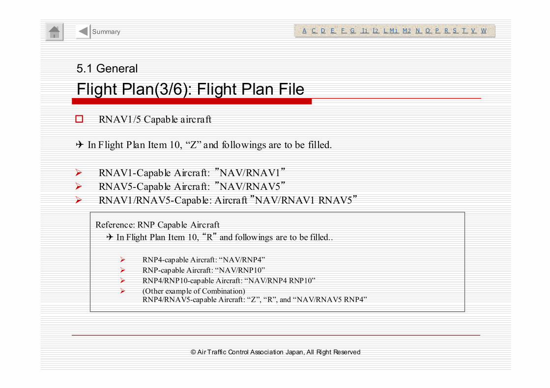
� RNAV1/5 Capable aircraft
✈ In Flight Plan Item 10, “Z” and followings are to be filled.
� RNAV1-Capable Aircraft: ”NAV/RNAV1”
� RNAV5-Capable Aircraft: ”NAV/RNAV5”
� RNAV1/RNAV5-Capable: Aircraft ”NAV/RNAV1 RNAV5”
A C D E F G I1 I2 L M1 M2 N O P R S T V WA C D E F G I1 I2 L M1 M2 N O P R S T V WSummary
Reference: RNP Capable Aircraft
✈ In Flight Plan Item 10, “R” and followings are to be filled..
� RNP4-capable Aircraft: “NAV/RNP4”
� RNP-capable Aircraft: “NAV/RNP10”
� RNP4/RNP10-capable Aircraft: “NAV/RNP4 RNP10”
� (Other example of Combination)RNP4/RNAV5-capable Aircraft: “Z”, “R”, and “NAV/RNAV5 RNP4”
© Air Traffic Control Association Japan, All Right Reserved
5.1 General
Flight Plan(4/6): Indication on Strip
A C D E F G I1 I2 L M1 M2 N O P R S T V WA C D E F G I1 I2 L M1 M2 N O P R S T V WSummary
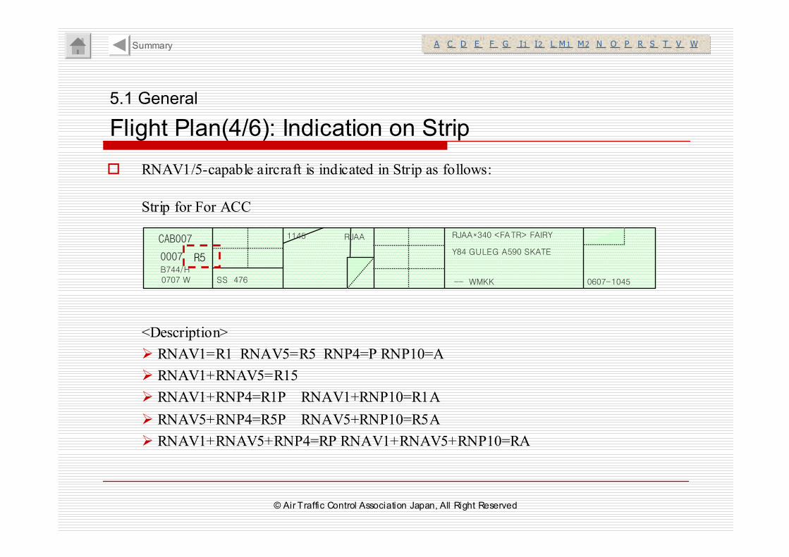
� RNAV1/5-capable aircraft is indicated in Strip as follows:
<Description>
� RNAV1=R1 RNAV5=R5 RNP4=P RNP10=A
� RNAV1+RNAV5=R15
� RNAV1+RNP4=R1P RNAV1+RNP10=R1A
� RNAV5+RNP4=R5P RNAV5+RNP10=R5A
� RNAV1+RNAV5+RNP4=RP RNAV1+RNAV5+RNP10=RA
CAB007
0007B744/H0707 W SS 476
1145 RJAA RJAA*340 <FATR> FAIRY
Y84 GULEG A590 SKATE
-- WMKK 0607-1045
R5
Strip for For ACC
© Air Traffic Control Association Japan, All Right Reserved
5.1 General
Flight Plan(5/6): Indication on Strip (Cont’d)
A C D E F G I1 I2 L M1 M2 N O P R S T V WA C D E F G I1 I2 L M1 M2 N O P R S T V WSummary
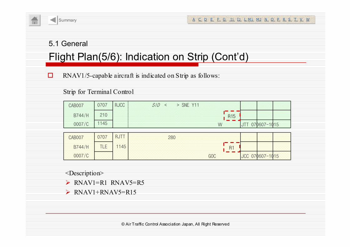
� RNAV1/5-capable aircraft is indicated on Strip as follows:
CAB007
0007/C
B744/H
0707
210
W1145
RJCC SID < > SNE Y11
JTT 070607-1015
280CAB007
0007/C
B744/H
0707
TLE 1145
RJTT
JCC 070607-1015 GOC
R15
R1
Strip for Terminal Control
<Description>
� RNAV1=R1 RNAV5=R5
� RNAV1+RNAV5=R15
© Air Traffic Control Association Japan, All Right Reserved
5.1 General
Flight Plan(6/6): Radar Scope
A C D E F G I1 I2 L M1 M2 N O P R S T V WA C D E F G I1 I2 L M1 M2 N O P R S T V WSummary
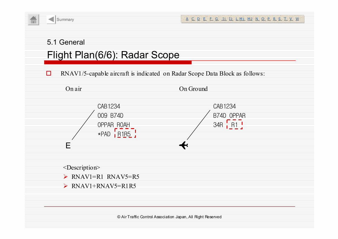
� RNAV1/5-capable aircraft is indicated on Radar Scope Data Block as follows:
CAB1234
B74D OPPAR
34R
CAB1234
009 B74D
OPPAR ROAH
*PAD
E
R1R5
R1
On air On Ground
<Description>
� RNAV1=R1 RNAV5=R5
� RNAV1+RNAV5=R1R5
© Air Traffic Control Association Japan, All Right Reserved
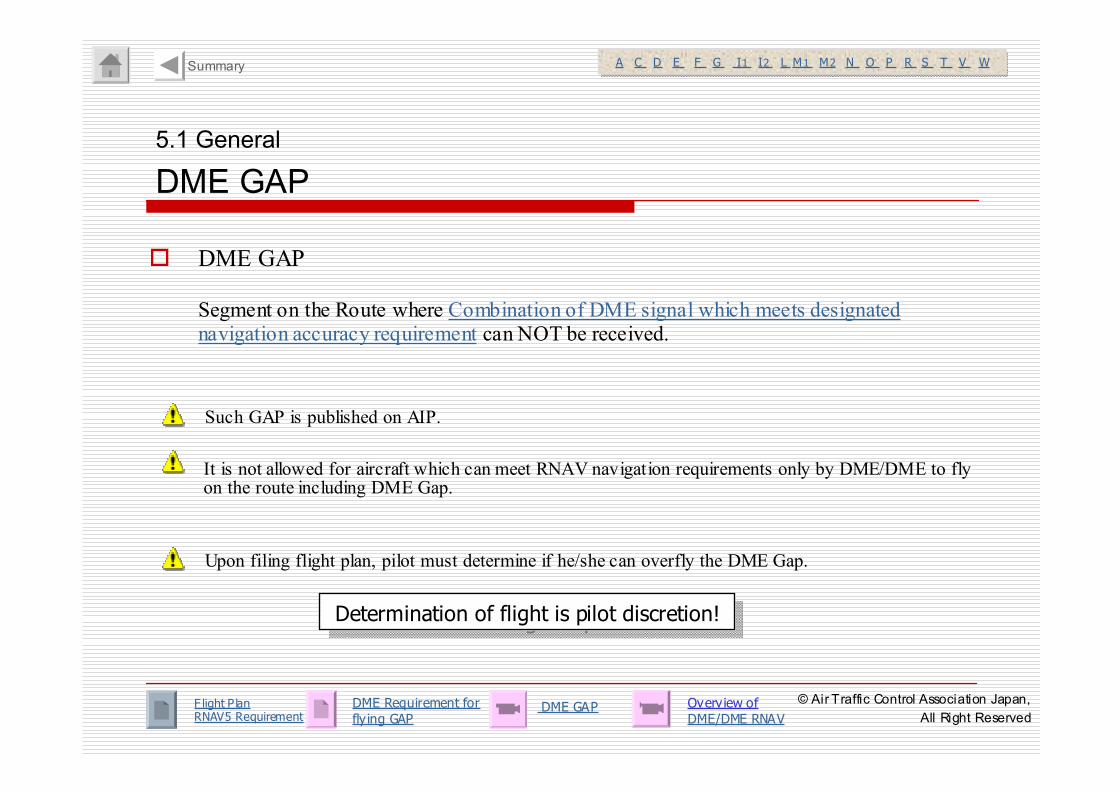
� DME GAP
Segment on the Route where Combination of DME signal which meets designated navigation accuracy requirement can NOT be received.
5.1 General
DME GAP
DME GAP Overview of DME/DME RNAV
Determination of flight is pilot discretion!Determination of flight is pilot discretion!
A C D E F G I1 I2 L M1 M2 N O P R S T V WA C D E F G I1 I2 L M1 M2 N O P R S T V WSummary
Such GAP is published on AIP.
Upon filing flight plan, pilot must determine if he/she can overfly the DME Gap.
It is not allowed for aircraft which can meet RNAV navigation requirements only by DME/DME to fly on the route including DME Gap.
F light P lan RNAV5 Requirement
DME Requirement for fly ing GAP
© Air Traffic Control Association Japan,
All Right Reserved
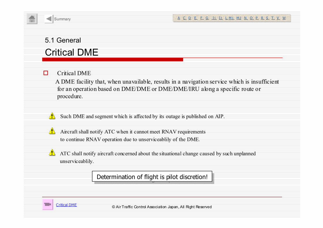
� Critical DME
A DME facility that, when unavailable, results in a navigation service which is insufficient
for an operation based on DME/DME or DME/DME/IRU along a specific route or
procedure.
5.1 General
Critical DME
Critical DME
Determination of flight is pilot discretion!Determination of flight is pilot discretion!
A C D E F G I1 I2 L M1 M2 N O P R S T V WA C D E F G I1 I2 L M1 M2 N O P R S T V WSummary
Such DME and segment which is affected by its outage is published on AIP.
Aircraft shall notify ATC when it cannot meet RNAV requirements
to continue RNAV operation due to unserviceablily of the DME.
ATC shall notify aircraft concerned about the situational change caused by such unplanned
unserviceablily.
© Air Traffic Control Association Japan, All Right Reserved
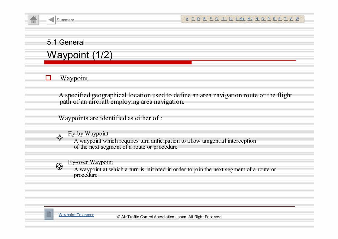
� Waypoint
A specified geographical location used to define an area navigation route or the flight path of an aircraft employing area navigation.
Waypoints are identified as either of :
Fly-by Waypoint
A waypoint which requires turn anticipation to allow tangential interception of the next segment of a route or procedure
Fly-over Waypoint
A waypoint at which a turn is initiated in order to join the next segment of a route or procedure
5.1 General
Waypoint (1/2)
Waypoint Tolerance
A C D E F G I1 I2 L M1 M2 N O P R S T V WA C D E F G I1 I2 L M1 M2 N O P R S T V WSummary
© Air Traffic Control Association Japan, All Right Reserved
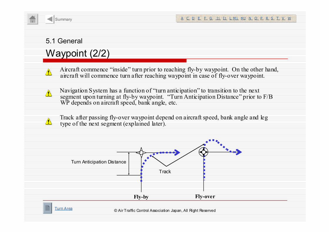
Aircraft commence “inside” turn prior to reaching fly-by waypoint. On the other hand, aircraft will commence turn after reaching waypoint in case of fly-over waypoint.
Navigation System has a function of “turn anticipation” to transition to the next segment upon turning at fly-by waypoint. “Turn Anticipation Distance” prior to F/B WP depends on aircraft speed, bank angle, etc.
Track after passing fly-over waypoint depend on aircraft speed, bank angle and leg type of the next segment (explained later).
Fly-overFly-by
Turn Anticipation Distance
Track
5.1 General
Waypoint (2/2)
Turn Area
A C D E F G I1 I2 L M1 M2 N O P R S T V WA C D E F G I1 I2 L M1 M2 N O P R S T V WSummary
© Air Traffic Control Association Japan, All Right Reserved
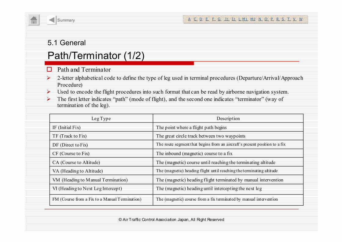
� Path and Terminator
� 2-letter alphabetical code to define the type of leg used in terminal procedures (Departure/Arrival/Approach
Procedure)
� Used to encode the flight procedures into such format that can be read by airborne navigation system.
� The first letter indicates “path” (mode of flight), and the second one indicates “terminator” (way of termination of the leg).
5.1 General
Path/Terminator (1/2)
The point where a flight path beginsIF (Initial Fix)
The (magnetic) course from a fix terminated by manual interventionFM (Course from a Fix to a Manual Termination)
The (magnetic) heading until intercepting the next legVI (Heading to Next Leg Intercept)
The (magnetic) heading flight terminated by manual interventionVM (Heading to Manual Termination)
The (magnetic) heading flight until reaching the terminating altitudeVA (Heading to Altitude)
The (magnetic) course until reaching the terminating altitudeCA (Course to Altitude)
The inbound (magnetic) course to a fixCF (Course to Fix)
The route segment that begins from an aircraft’s present position to a fixDF (Direct to Fix)
The great circle track between two waypointsTF (Track to Fix)
DescriptionLeg Type
A C D E F G I1 I2 L M1 M2 N O P R S T V WA C D E F G I1 I2 L M1 M2 N O P R S T V WSummary
© Air Traffic Control Association Japan, All Right Reserved
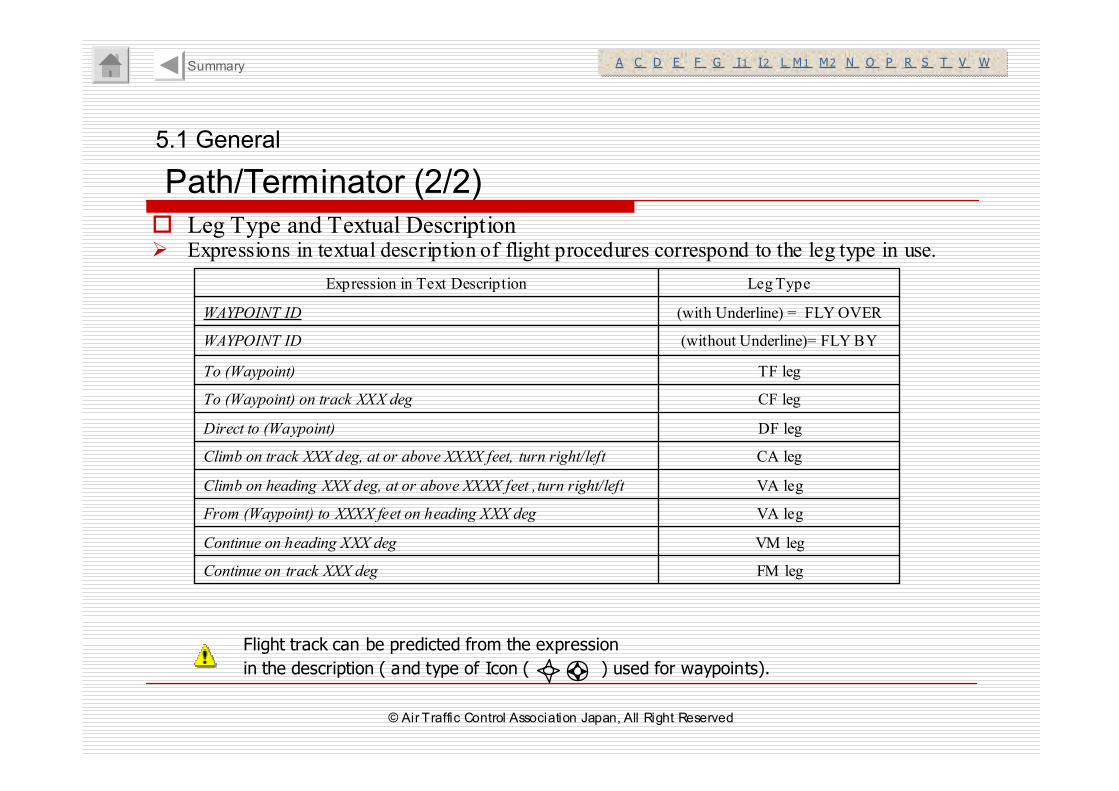
� Leg Type and Textual Description� Expressions in textual description of flight procedures correspond to the leg type in use.
5.1 General
Path/Terminator (2/2)
FM legContinue on track XXX deg
VM legContinue on heading XXX deg
VA legFrom (Waypoint) to XXXX feet on heading XXX deg
VA legClimb on heading XXX deg, at or above XXXX feet , turn right/left
CA legClimb on track XXX deg, at or above XXXX feet, turn right/left
DF legDirect to (Waypoint)
CF legTo (Waypoint) on track XXX deg
TF legTo (Waypoint)
(without Underline)= FLY BYWAYPOINT ID
(with Underline) = FLY OVERWAYPOINT ID
Leg TypeExpression in Text Description
Flight track can be predicted from the expression
in the description ( and type of Icon ( ) used for waypoints).
A C D E F G I1 I2 L M1 M2 N O P R S T V WA C D E F G I1 I2 L M1 M2 N O P R S T V WSummary
© Air Traffic Control Association Japan, All Right Reserved
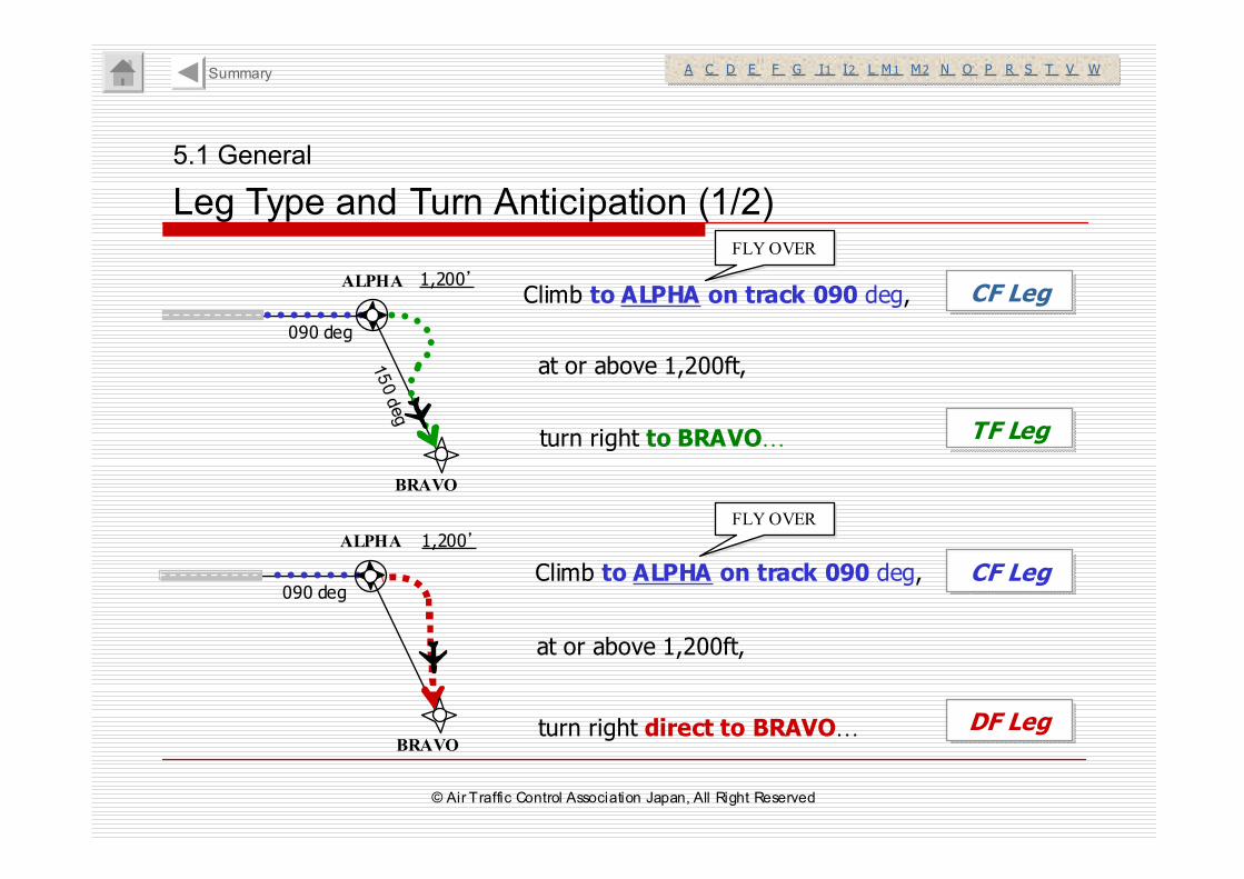
Climb to ALPHA on track 090 deg, ALPHA
BRAVO
090 deg
1,200’
ALPHA
BRAVO
090 deg
1,200’
turn right to BRAVO…
Climb to ALPHA on track 090 deg,
turn right direct to BRAVO…
at or above 1,200ft,
at or above 1,200ft,
CF LegCF Leg
TF LegTF Leg
CF LegCF Leg
DF LegDF Leg
FLY OVERFLY OVER
FLY OVERFLY OVER
150 deg
5.1 General
Leg Type and Turn Anticipation (1/2)
A C D E F G I1 I2 L M1 M2 N O P R S T V WA C D E F G I1 I2 L M1 M2 N O P R S T V WSummary
© Air Traffic Control Association Japan, All Right Reserved
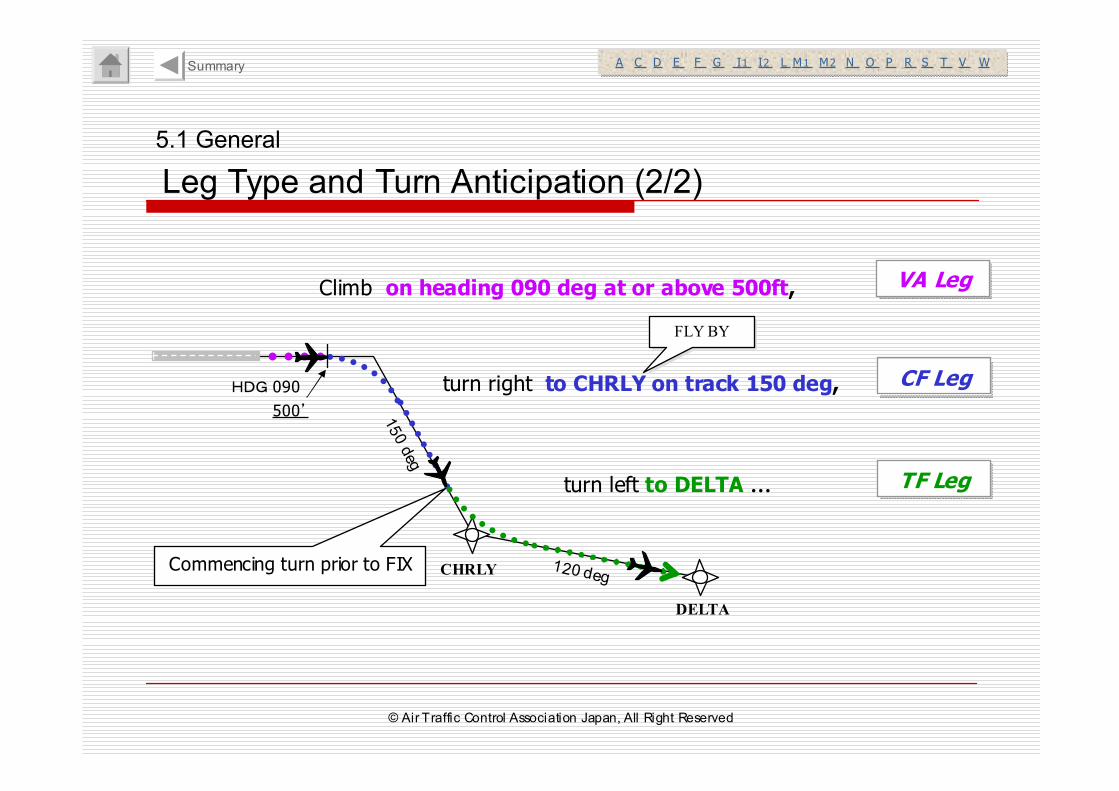
Climb on heading 090 deg at or above 500ft,
turn right to CHRLY on track 150 deg,
turn left to DELTA …
VA LegVA Leg
CF LegCF Leg
TF LegTF Leg
FLY BYFLY BY
CHRLY
DELTA
150 deg
HDG 090
120 deg
500’
Commencing turn prior to FIX
A C D E F G I1 I2 L M1 M2 N O P R S T V WA C D E F G I1 I2 L M1 M2 N O P R S T V W
5.1 General
Leg Type and Turn Anticipation (2/2)
Summary
© Air Traffic Control Association Japan, All Right Reserved

5. Terminal/Enroute ATC Procedures
5.1 General
5.2 Terminal RNAV ATC Procedures
(RNAV1)
5.3 Enroute RNAV ATC Procedures (RNAV5)
Summary
© Air Traffic Control Association Japan, All Right Reserved
5.2 RNAV 1
Application of ATC Procedure
A C D E F G I1 I2 L M1 M2 N O P R S T V WA C D E F G I1 I2 L M1 M2 N O P R S T V W
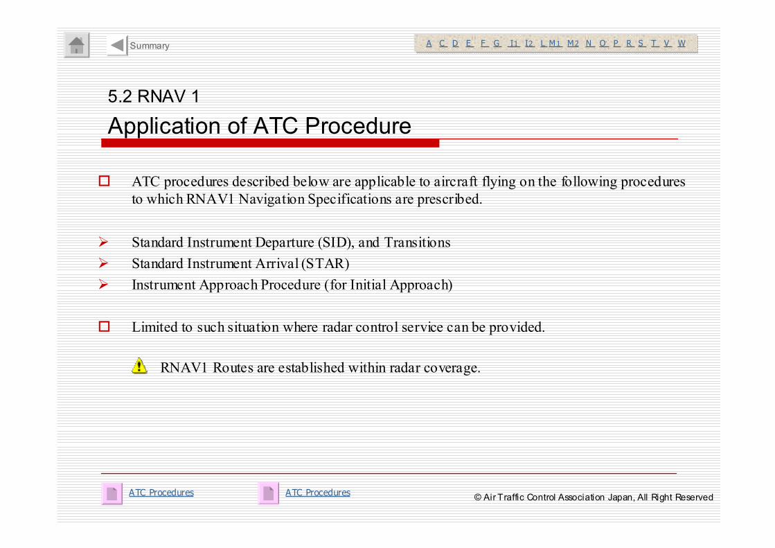
� ATC procedures described below are applicable to aircraft flying on the following procedures
to which RNAV1 Navigation Specifications are prescribed.
� Standard Instrument Departure (SID), and Transitions
� Standard Instrument Arrival (STAR)
� Instrument Approach Procedure (for Initial Approach)
� Limited to such situation where radar control service can be provided.
Summary
RNAV1 Routes are established within radar coverage.
ATC ProceduresATC Procedures© Air Traffic Control Association Japan, All Right Reserved
5.2 RNAV 1
Radar Vector
A C D E F G I1 I2 L M1 M2 N O P R S T V WA C D E F G I1 I2 L M1 M2 N O P R S T V W
� Upon vectoring to RNAV1 Route, vector is to be conducted toward a fix on the route.
� Instruct “Direct to a fix” upon terminating the vector.
e.g. “Fly heading 070 for vector to BRAVO.”
“Resume own navigation direct BRAVO.”
Summary
DIRECT TO WAYPOINT© Air Traffic Control Association Japan, All Right Reserved
5.2 RNAV 1
Direct to a Fix
A C D E F G I1 I2 L M1 M2 N O P R S T V WA C D E F G I1 I2 L M1 M2 N O P R S T V W
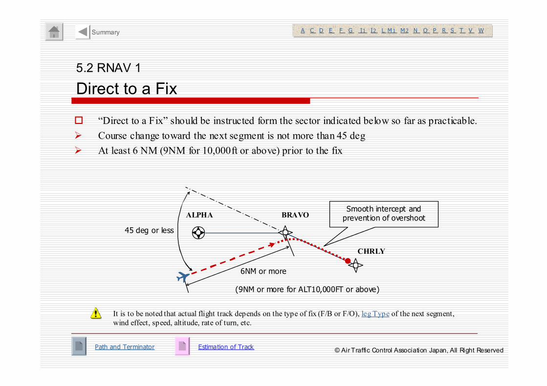
� “Direct to a Fix” should be instructed form the sector indicated below so far as practicable.
� Course change toward the next segment is not more than 45 deg
� At least 6 NM (9NM for 10,000ft or above) prior to the fix
It is to be noted that actual flight track depends on the type of fix (F/B or F/O), leg Type of the next segment,
wind effect, speed, altitude, rate of turn, etc.
ALPHA BRAVO
CHRLY
45 deg or less
6NM or more
(9NM or more for ALT10,000FT or above)
Smooth intercept and prevention of overshoot
Estimation of TrackPath and Terminator
Summary
© Air Traffic Control Association Japan, All Right Reserved
5.2 RNAV 1
Contingency Procedures
A C D E F G I1 I2 L M1 M2 N O P R S T V WA C D E F G I1 I2 L M1 M2 N O P R S T V W
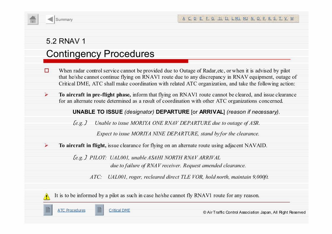
� When radar control service cannot be provided due to Outage of Radar,etc, or when it is advised by pilot
that he/she cannot continue flying on RNAV1 route due to any discrepancy in RNAV equipment, outage of
Critical DME, ATC shall make coordination with related ATC organization, and take the following action:
� To aircraft in pre-flight phase, inform that flying on RNAV1 route cannot be cleared, and issue clearance
for an alternate route determined as a result of coordination with other ATC organizations concerned.
UNABLE TO ISSUE (designator) DEPARTURE [or ARRIVAL] (reason if necessary).
〔e.g.〕 Unable to issue MORIYA ONE RNAV DEPARTURE due to outage of ASR.
Expect to issue MORIYA NINE DEPARTURE, stand by for the clearance.
� To aircraft in flight, issue clearance for flying on an alternate route using adjacent NAVAID.
〔e.g.〕 PILOT: UAL001, unable ASAHI NORTH RNAV ARRIVAL
due to failure of RNAV receiver. Request amended clearance.
ATC: UAL001, roger, recleared direct TLE VOR, hold north, maintain 9,000ft.
It is to be informed by a pilot as such in case he/she cannot fly RNAV1 route for any reason.
ATC Procedures Critical DME
Summary
© Air Traffic Control Association Japan, All Right Reserved
5.2 RNAV 1
Confirmation of Capability of Flight
A C D E F G I1 I2 L M1 M2 N O P R S T V WA C D E F G I1 I2 L M1 M2 N O P R S T V W
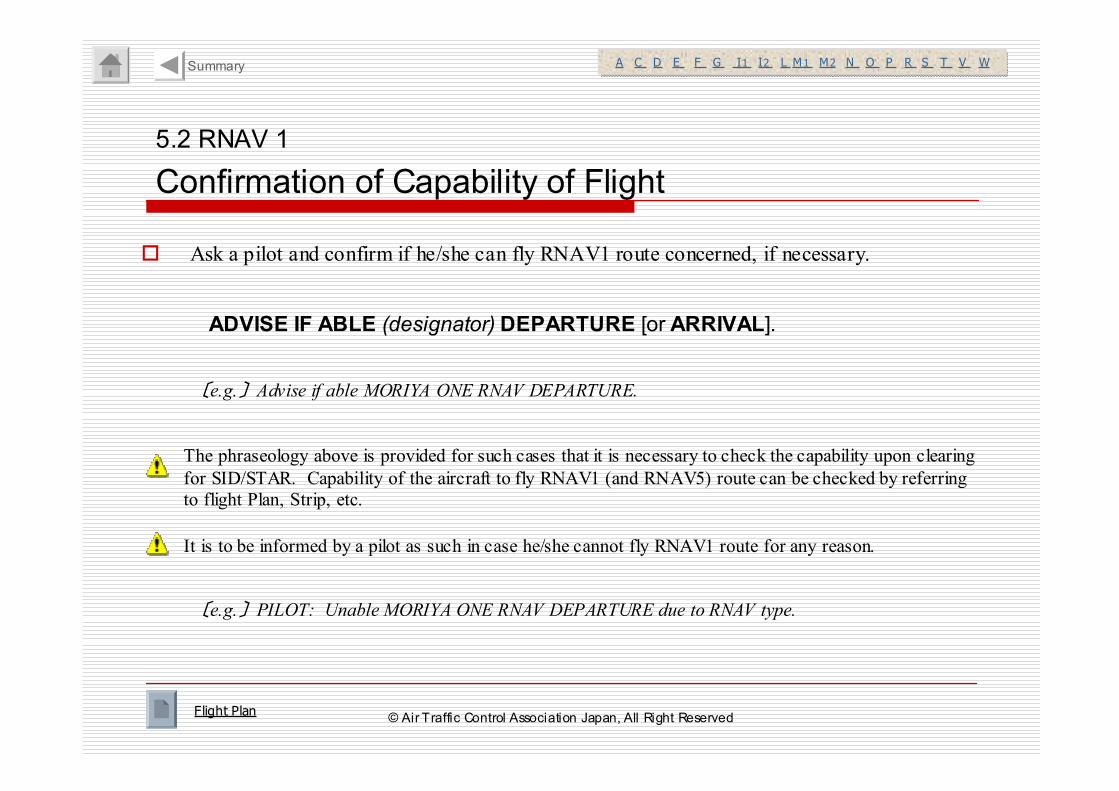
� Ask a pilot and confirm if he/she can fly RNAV1 route concerned, if necessary.
The phraseology above is provided for such cases that it is necessary to check the capability upon clearing
for SID/STAR. Capability of the aircraft to fly RNAV1 (and RNAV5) route can be checked by referring
to flight Plan, Strip, etc.
ADVISE IF ABLE (designator) DEPARTURE [or ARRIVAL].
Flight Plan
〔e.g.〕 Advise if able MORIYA ONE RNAV DEPARTURE.
It is to be informed by a pilot as such in case he/she cannot fly RNAV1 route for any reason.
〔e.g.〕 PILOT: Unable MORIYA ONE RNAV DEPARTURE due to RNAV type.
Summary
© Air Traffic Control Association Japan, All Right Reserved
Note RWY34R: 5.0% climb gradient required up to 520ft.
RWY34L: 5.0% climb gradient required up to 680ft.
Rcmd. Path
Terminator
Fix ID
(Waypoint
Name)
MAG Track
(TRUE Track)
Distance
(NM)
Turn
Direction Altitude(FT)
Speed Limit(kt)
Vertical Angle
Navigation
Performance Fly
Over
----VA ---- ---- 5 00
TF
DF SNE01
SNE02
----
---- 3.8
----
33 7°°°°( 329.9°°°°)
010°°°°(00 3.0°°°°)
---- ----
----
----
----
----
----
----
----
L
----
R RNAV1
RNAV1
RNAV1
TF SNE ---- 15 .8 010°°°°(00 3.0°°°°)
---------------- RNAV1
RWY34R/34L
Not e RWY34R: 5.0% climb gradient required up to 520ft.
RWY34L: 5.0% climb gradient required up to 680ft.
Rcmd. Path
Terminator
Fix ID
(Waypoint
Name)
MAG Track
(TRUE Track)
Distance
(NM)
Turn
Direction Altitude(FT)
Speed Limit(kt)
Vertical Angle
Navigation
Performance Fly
Over
----VA ---- ---- 5 00
TF
DF SNE01
SNE02
----
---- 3.8
----
33 7°°°°( 329.9°°°°)
010°°°°(00 3.0°°°°)
---- ----
----
----
----
----
----
----
----
L
----
R RNAV1
RNAV1
RNAV1
TF SNE ---- 15 .8 010°°°°(00 3.0°°°°)
---------------- RNAV1
RWY34R/34L
+
5.2 RNAV 1
Example of Publication (1/5)
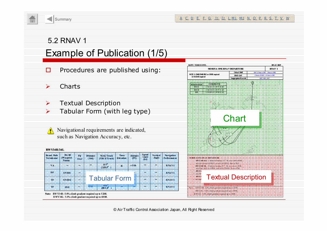
� Procedures are published using:
� Charts
� Textual Description
� Tabular Form (with leg type)
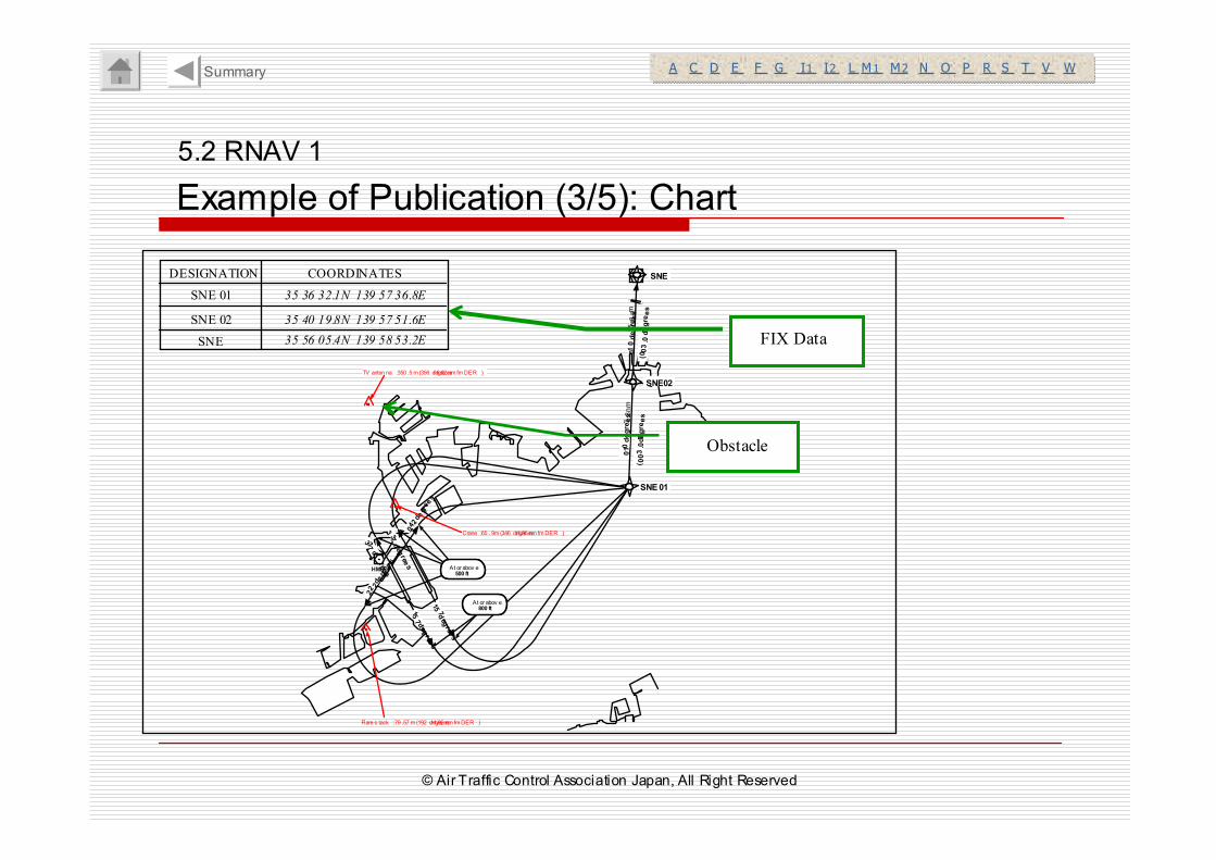
DESIGNATION COORDINATES
SNE 01 3 5 36 32.1 N 1 39 57 36. 8E
SNE 02
SNE
3 5 40 19.8 N 1 39 57 51. 6E
3 5 56 05.4 N 1 39 58 53. 2E
DESIGNATION COORDINATESDESIGNATION COORDINATES
SNE 01 3 5 36 32.1 N 1 39 57 36. 8E
SNE 02
SNE
3 5 40 19.8 N 1 39 57 51. 6E
3 5 56 05.4 N 1 39 58 53. 2E
MORIYA ONE RNAV DEPARTURE
RWY16R/16L:C limb on h eadi ng 157°M, at o r above 800ft,
tu rn left, d irect t o SNE01, t urn le ft to SNE02, then to SNE.
RWY34R/ 34L :Cl imb on hea ding 337°M, at o r above 500ft ,
tu rn ri ght , di rec t to SNE01 , tu rn left t o SNE02 , th en t o SNE.
RWY04: Climb on head ing 042°M , a t or above 500 ft ,
tu rn left, d irect t o SNE01, t urn le ft to SNE02, then to SNE.
RWY22: Climb on head ing 222°M, a t or above 500 ft ,
turn r ig ht, direct to SNE01, turn l eft to SNE02, the n to SNE.
Note : RWY34R: 5. 0% cl imb gradient required up to 520ft .
RWY34L: 5.0% cl imb gradient required up to 680ft .
RWY22 : 5. 0% cl imb gradient required up to 560ft .
MORIYA ONE RNAV DEPARTURE RNAV 1
Criti cal DME
DME GAP
Inappropriat e Navai ds
NOTE 1) DME/DME/IRU or GNSS requi red
2) RADAR required
GOC (5.0nm to SNE – 2.0nm to SNE)
2.0nm to SNE02 –10.8nm to SNE
SHT, YOK, HUT
RJTT / TOKYO INTL RNAV DEP
MORIYA ONE RNAV DEPARTURE RNAV 1
Criti cal DME
DME GAP
Inappropriat e Navai ds
NOTE 1) DME/DME/IRU or GNSS requi red
2) RADAR required
Criti cal DME
DME GAP
Inappropriat e Navai ds
NOTE 1) DME/DME/IRU or GNSS requi red
2) RADAR required
GOC (5.0nm to SNE – 2.0nm to SNE)
2.0nm to SNE02 –10.8nm to SNE
SHT, YOK, HUT
RJTT / TOKYO INTL RNAV DEP
ChartChart
Textual DescriptionTextual Description
Navigational requirements are indicated,
such as Navigation Accuracy, etc.
A C D E F G I1 I2 L M1 M2 N O P R S T V WA C D E F G I1 I2 L M1 M2 N O P R S T V WSummary
Tabular FormTabular Form
© Air Traffic Control Association Japan, All Right Reserved
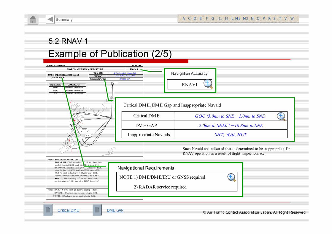
5.2 RNAV 1
Example of Publication (2/5)
A C D E F G I1 I2 L M1 M2 N O P R S T V WA C D E F G I1 I2 L M1 M2 N O P R S T V WSummary
Critical DME DME GAP
DESIGNATION COORDINATES
SNE 01 3 5 36 32.1 N 1 39 57 36. 8E
SNE 02
SNE
3 5 40 19.8 N 1 39 57 51. 6E
3 5 56 05.4 N 1 39 58 53. 2E
DESIGNATION COORDINATESDESIGNATION COORDINATES
SNE 01 3 5 36 32.1 N 1 39 57 36. 8E
SNE 02
SNE
3 5 40 19.8 N 1 39 57 51. 6E
3 5 56 05.4 N 1 39 58 53. 2E
MORIYA ONE RNAV DEPARTURE
RWY16R/16L:C limb on h eadi ng 157°M, at o r above 800ft,
tu rn left, d irect t o SNE01, t urn le ft to SNE02, then to SNE.
RWY34R/ 34L :Cl imb on hea ding 337°M, at o r above 500ft ,
tu rn ri ght , di rec t to SNE01 , tu rn left t o SNE02 , th en t o SNE.
RWY04: Climb on head ing 042°M , a t or above 500 ft ,
tu rn left, d irect t o SNE01, t urn le ft to SNE02, then to SNE.
RWY22: Climb on head ing 222°M, a t or above 500 ft ,
turn r ig ht, direct to SNE01, turn l eft to SNE02, the n to SNE.
Note : RWY34R: 5. 0% cl imb gradient required up to 520ft .
RWY34L: 5.0% cl imb gradient required up to 680ft .
RWY22 : 5. 0% cl imb gradient required up to 560ft .
MORIYA ONE RNAV DEPARTURE RNAV 1
Criti cal DME
DME GAP
Inappropriat e Navai ds
NOTE 1) DME/DME/IRU or GNSS requi red
2) RADAR required
GOC (5.0nm to SNE – 2.0nm to SNE)
2.0nm to SNE02 –10.8nm to SNE
SHT, YOK, HUT
RJTT / TOKYO INTL RNAV DEP
MORIYA ONE RNAV DEPARTURE RNAV 1
Criti cal DME
DME GAP
Inappropriat e Navai ds
NOTE 1) DME/DME/IRU or GNSS requi red
2) RADAR required
Criti cal DME
DME GAP
Inappropriat e Navai ds
NOTE 1) DME/DME/IRU or GNSS requi red
2) RADAR required
GOC (5.0nm to SNE – 2.0nm to SNE)
2.0nm to SNE02 –10.8nm to SNE
SHT, YOK, HUT
RJTT / TOKYO INTL RNAV DEP
RNAV1
Navigation Accuracy
++++++++
Such Navaid are indicat ed that is determined to be inappropriate for
RNAV operation as a result of flight inspection, etc.
Navigational Requirements
NOTE 1) DME/DME/IRU or GNSS required
2) RADAR service required
++++++++
Critical DME, DME Gap and Inappropriate Navaid
++++++++Critical DME
DME GAP
Inappropriate Navaids
GOC (5.0nm to SNE-2.0nm to SNE
2.0nm to SNE02-10.8nm to SNE
SHT, YOK, HUT
© Air Traffic Control Association Japan, All Right Reserved
DESIGNATION COORDINATES
SNE 01 35 36 32.1N 139 57 36.8E
SNE 02
SNE
35 40 19.8N 139 57 51.6E
35 56 05.4N 139 58 53.2E
5.2 RNAV 1
Example of Publication (3/5): Chart
HME
SNE01
SNE
337
degree
s
3 37degree
s
22 2degrees
042degrees
157 degree
s157degree
s
010
degrees
SNE02
010degrees
3.8nm
15.8nm
Flare s tack :79 .57m (192 degre es/ 1.92 nm fm DER )
Crane :65 . 9m (346 degre es/1.95 nm fm DER )
TV anten na :350 .5m (356 degre es/ 6.02 nm fm DER )
(003.0degrees
T)( 003.0degrees
T)
At or abov e800 ft
At or abov e500 ft
FIX Data
A C D E F G I1 I2 L M1 M2 N O P R S T V WA C D E F G I1 I2 L M1 M2 N O P R S T V WSummary
Obstacle
© Air Traffic Control Association Japan, All Right Reserved
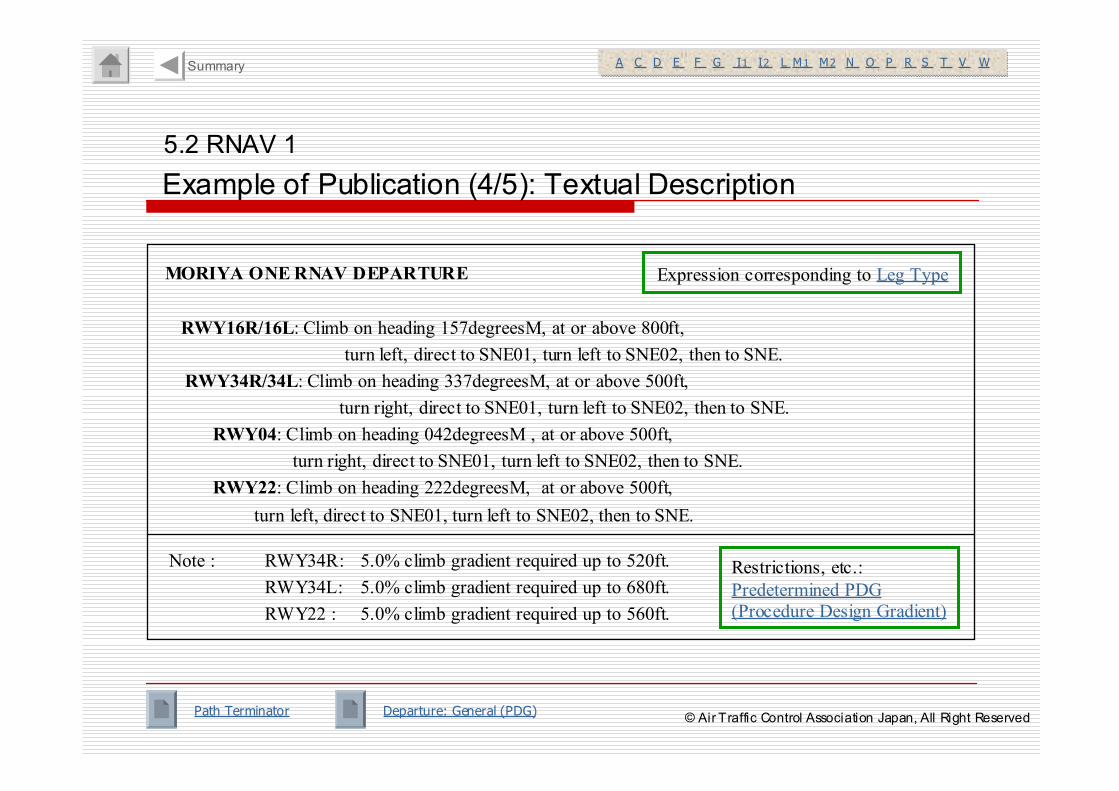
MORIYA ONE RNAV DEPARTURE
RWY16R/16L: Climb on heading 157degreesM, at or above 800ft,
turn left, direct to SNE01, turn left to SNE02, then to SNE.
RWY34R/34L: Climb on heading 337degreesM, at or above 500ft,
turn right, direct to SNE01, turn left to SNE02, then to SNE.
RWY04: Climb on heading 042degreesM , at or above 500ft,
turn right, direct to SNE01, turn left to SNE02, then to SNE.
RWY22: Climb on heading 222degreesM, at or above 500ft,
turn left, direct to SNE01, turn left to SNE02, then to SNE.
Note : RWY34R: 5.0% climb gradient required up to 520ft.
RWY34L: 5.0% climb gradient required up to 680ft.
RWY22 : 5.0% climb gradient required up to 560ft.
5.2 RNAV 1
Example of Publication (4/5): Textual Description
Restrictions, etc.:
Predetermined PDG
(Procedure Design Gradient)
Expression corresponding to Leg Type
A C D E F G I1 I2 L M1 M2 N O P R S T V WA C D E F G I1 I2 L M1 M2 N O P R S T V WSummary
Path Terminator Departure: General (PDG)© Air Traffic Control Association Japan, All Right Reserved
5.2 RNAV 1
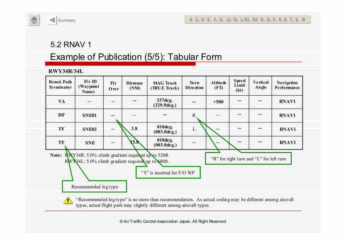
Example of Publication (5/5): Tabular Form
Recommended leg type
“Y” is inserted for F/O WP
“R” for right turn and “L” for left turn
A C D E F G I1 I2 L M1 M2 N O P R S T V WA C D E F G I1 I2 L M1 M2 N O P R S T V WSummary
“Recommended leg type” is no more than recommendation. As actual coding may be different among aircraft
types, actual flight path may slightly different among aircraft types.
Note: RWY34R: 5.0% climb gradient required up to 520ft.
RWY34L: 5.0% climb gradient required up to 680ft.
Rcmd. Path
Terminator
Fix ID(Waypoint
Name)
MAG Track(TRUE Track)
Distance(NM)
Turn Direction
Altitude(FT)
Speed Limit(kt)
Vertical Angle
Navigation Performance
Fly
Over
----VA ---- ---- +500
TF
DF SNE01
SNE02
----
---- 3.8
----
337deg.(329.9deg.)
010deg.(003.0deg.)
---- ----
----
----
----
----
----
----
----
R
L
---- RNAV1
RNAV1
RNAV1
TF SNE ---- 15.8 010deg.(003.0deg.)
---------------- RNAV1
RWY34R/34L
© Air Traffic Control Association Japan, All Right Reserved
5. Terminal/Enroute ATC Procedures
5.1 General
5.2 Terminal RNAV ATC Procedures
(RNAV1)
5.3 Enroute RNAV ATC Procedures (RNAV5)
Summary
© Air Traffic Control Association Japan, All Right Reserved
5.3 RNAV 5
Application of ATC Procedure
A C D E F G I1 I2 L M1 M2 N O P R S T V WA C D E F G I1 I2 L M1 M2 N O P R S T V W
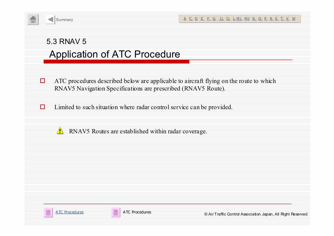
� ATC procedures described below are applicable to aircraft flying on the route to which
RNAV5 Navigation Specifications are prescribed (RNAV5 Route).
� Limited to such situation where radar control service can be provided.
RNAV5 Routes are established within radar coverage.
Summary
ATC ProceduresATC Procedures© Air Traffic Control Association Japan, All Right Reserved
5.3 RNAV 5
Radar Vector
A C D E F G I1 I2 L M1 M2 N O P R S T V WA C D E F G I1 I2 L M1 M2 N O P R S T V W
� Upon vectoring to RNAV5 Route, vector is to be conducted toward the route or
toward a fix on the route.
� Instruct “Direct to a fix” upon terminating the vector.
e.g. “Fly heading 070 for vector to BRAVO.”
“Resume own navigation direct BRAVO.”
Summary
© Air Traffic Control Association Japan, All Right Reserved
5.3 RNAV 5
Direct to a Fix
A C D E F G I1 I2 L M1 M2 N O P R S T V WA C D E F G I1 I2 L M1 M2 N O P R S T V W
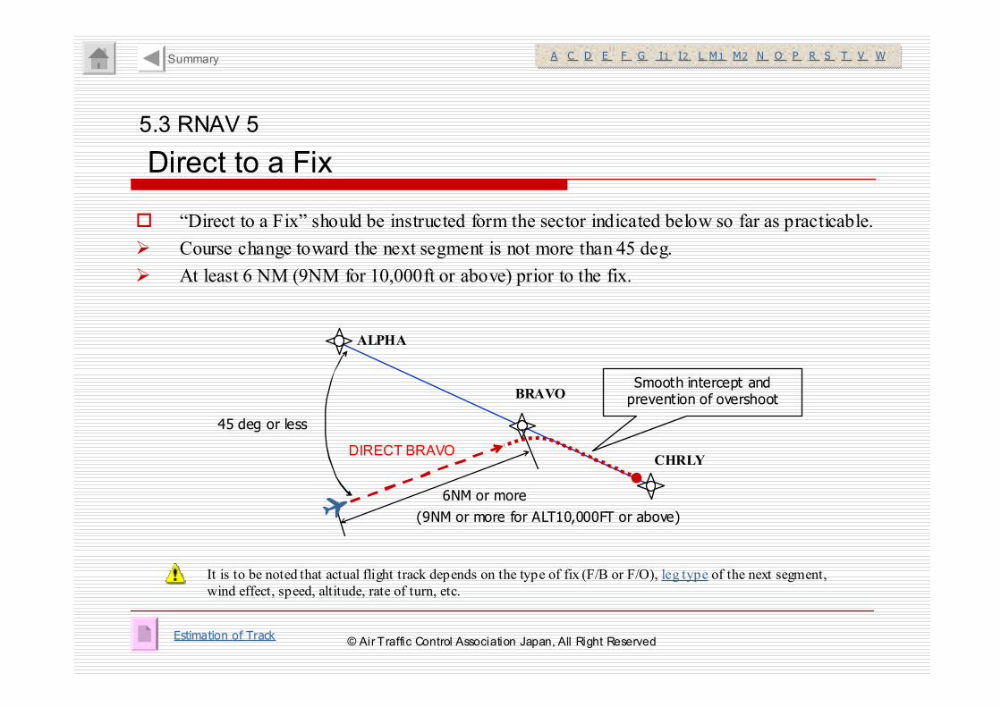
� “Direct to a Fix” should be instructed form the sector indicated below so far as practicable.
� Course change toward the next segment is not more than 45 deg.
� At least 6 NM (9NM for 10,000ft or above) prior to the fix.
It is to be noted that actual flight track depends on the type of fix (F/B or F/O), leg type of the next segment,
wind effect, speed, altitude, rate of turn, etc.
ALPHA
BRAVO
CHRLY
45 deg or less
6NM or more
(9NM or more for ALT10,000FT or above)
Smooth intercept and prevention of overshoot
Estimation of Track
DIRECT BRAVO
Summary
© Air Traffic Control Association Japan, All Right Reserved
5.3 RNAV 5
Contingency Procedures
A C D E F G I1 I2 L M1 M2 N O P R S T V WA C D E F G I1 I2 L M1 M2 N O P R S T V W
� When radar control service cannot be provided due to Outage of Radar,etc, or when it is advised by pilot
that he/she cannot continue flying on RNAV5 route due to any discrepancy in RNAV equipment, outage of
Critical DME, ATC shall make coordination with related ATC organization, and take the following action:
� To aircraft in pre-flight phase, inform that flying on RNAV5 route cannot be cleared, and issue
clearance for an alternate route determined as a result of coordination with other ATC organizations
concerned.
UNABLE TO ISSUE (RNAV route designator), (reason).
� To aircraft in flight, issue clearance for flying on an alternate route using adjacent NAVAID.
〔e.g.〕 PILOT: UAL001, unable Y10 due to failure of RNAV receiver.
Request amended clearance.
ATC: UAL001, roger, recleared direct TLE VOR, hold north, maintain 9,000ft.
It is to be informed by a pilot as such in case he/she cannot fly RNAV5 route for any reason.
Critical DME
Summary
ATC Procedures© Air Traffic Control Association Japan, All Right Reserved
6. RNAV Approach ATC Procedures
� Application of ATC Procedure
� Radar Vector
� Direct to a Fix
� Approach Clearance / Speed Control
Summary
© Air Traffic Control Association Japan, All Right Reserved
6. RNAV Approach
Application of ATC Procedure
A C D E F G I1 I2 L M1 M2 N O P R S T V WA C D E F G I1 I2 L M1 M2 N O P R S T V W
� RNAV(GNSS)Approach Procedures* are established
* Meet Navigation Specification for “RNP APCH”, however, published as “RNAV (GNSS)
RWY XX APCH” considering the current situation that such procedures has already been
published.
� For RNAV(GNSS)Approach, Initial approaches which have T/Y Bar arrangement are
established as well as STAR.
Missed Approach Procedures are designed based on conventional navigation in case that
approach cannot be continued due to discrepancy of GNSS, etc.
Summary
T/Y Bar Publication – Contingency Procedure© Air Traffic Control Association Japan, All Right Reserved
6. RNAV Approach
Radar Vector
A C D E F G I1 I2 L M1 M2 N O P R S T V WA C D E F G I1 I2 L M1 M2 N O P R S T V W
� Upon vectoring to RNAV Approach Procedure, vector is to be conducted toward Initial
Approach Fix (IAF) or Intermediate Approach Fix (IF).
� Instruct “Direct to a fix” upon terminating the vector.
e.g. “Fly heading 070 for vector to PUNCH.”
“Resume own navigation direct ROCCA.”
Summary
© Air Traffic Control Association Japan, All Right Reserved
6. RNAV Approach
Direct to a Fix
A C D E F G I1 I2 L M1 M2 N O P R S T V WA C D E F G I1 I2 L M1 M2 N O P R S T V W
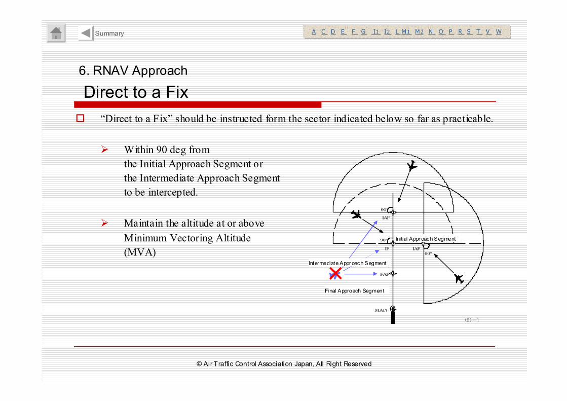
� “Direct to a Fix” should be instructed form the sector indicated below so far as practicable.
� Within 90 deg from
the Initial Approach Segment or
the Intermediate Approach Segment
to be intercepted.
� Maintain the altitude at or above
Minimum Vectoring Altitude
(MVA)
Summary
中間進入セグメント
最終進入セグメント
初期進入セグメント
90°
90°
90°
IAF
IAF
IF
FAF
MAPt
(2)-1
×
Initial Appr oach Segment
Intermediate Appr oach Segment
Final Approach Segment
© Air Traffic Control Association Japan, All Right Reserved
6. RNAV Approach
Approach Clearance/Speed Control
A C D E F G I1 I2 L M1 M2 N O P R S T V WA C D E F G I1 I2 L M1 M2 N O P R S T V W
� Approach clearance is to be issued before the aircraft reaches IAF/IF.
� Approach clearance is to be issued with the distance from the fix.
� IAS over 210kt shall not be instructed upon crossing IAF.
e.g. “10NM south of EMINA. Cleared for RNAV RWY30 approach.”
(Sensor Type) indicated in the bracket in the procedure title
is not included in the clearance.
Approach procedure Title : RNAV (GNSS) RWY30
T/Y bar - Initial Approach Segment
Summary
© Air Traffic Control Association Japan, All Right Reserved
Summary of Summary of RNAV ATC ProcedureRNAV ATC Procedures s
© Air Traffic Control Association Japan, All Right Reserved
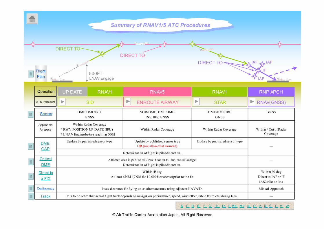
500FT
RNAV1
SID
RNAV5
ENROUTE AIRWAY
RNAV1
STAR
IAF IAF
RNP APCH
RNAV(GNSS)
DIRECT TO
UP DATE
Flight
Plan
DIRECT TO
DIRECT TO
IF
IAFLNAV Engage
―It is to be noted that actual flight track depends on navigation performance, speed, wind effect, rate o f turn etc. during turn.
Determination of flight is pilot discretion.
Missed ApproachIssue clearance for flying on an alternate route using adjacent NAVAID.
Within 90 deg
Direct to IAFor IF
IAS210kt or less
Within 45deg
At least 6 NM (9NM for 10,000ft or above) prior to the fix
―
Update by published sensor typeUpdate by published sensor type
DR (not allowed at moment)
Update by published sensor type
―Affected area is published. / Notification to Unplanned Outage
Determination of flight is pilot discretion.
Within / Out of Radar
Coverage
GNSS
Within Radar Coverage
DME/DME/IRU
GNSS
Within Radar Coverage
VOR/DME, DME/DME
INS, IRS, GNSS
Within Radar Coverage
* RWY POSITION UP DATE (IRU)
* LNAV Engage before reaching 500ft
DME/DME/IRU
GNSS
Applicable
Airspace
Operation
Track
DME
GAP
Sensor
Direct to
a FIX
Critical
DME
Contingency
AT CA J ●AT CA J ●
AT CAJ ●
AT CAJ ●
A TC AJ ●A TC AJ ●
A TC AJ ●A TC AJ ●
AT CA J ●AT CA J ●
Summary of RNAV1/5 ATC Procedures
ATC Procedure
A C D E F G I1 I2 L M1 M2 N O P R S T V WA C D E F G I1 I2 L M1 M2 N O P R S T V W
© Air Traffic Control Association Japan, All Right Reserved
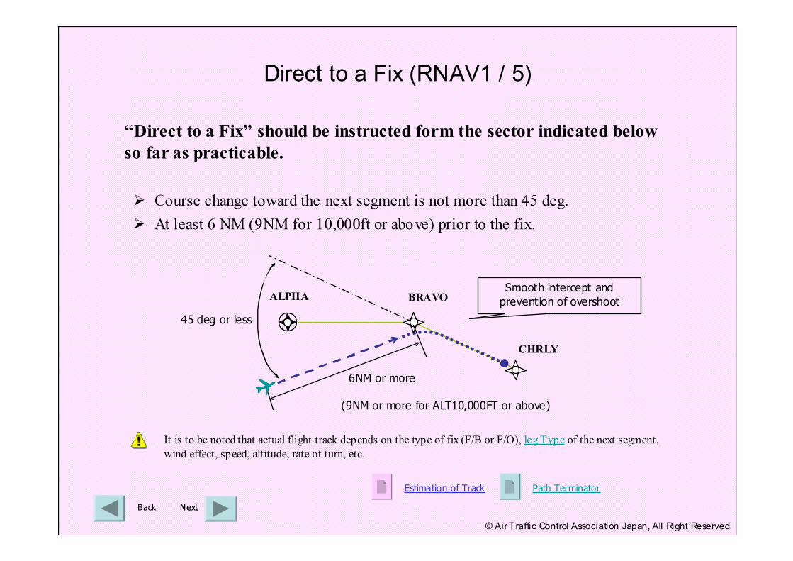
It is to be noted that actual flight track depends on the type of fix (F/B or F/O), leg Type of the next segment,
wind effect, speed, altitude, rate of turn, etc.
ALPHA BRAVO
CHRLY
45 deg or less
6NM or more
(9NM or more for ALT10,000FT or above)
Smooth intercept and
prevention of overshoot
Estimation of Track Path Terminator
Direct to a Fix (RNAV1 / 5)
Back NextNext
“Direct to a Fix” should be instructed form the sector indicated below
so far as practicable.
� Course change toward the next segment is not more than 45 deg.
� At least 6 NM (9NM for 10,000ft or above) prior to the fix.
© Air Traffic Control Association Japan, All Right Reserved
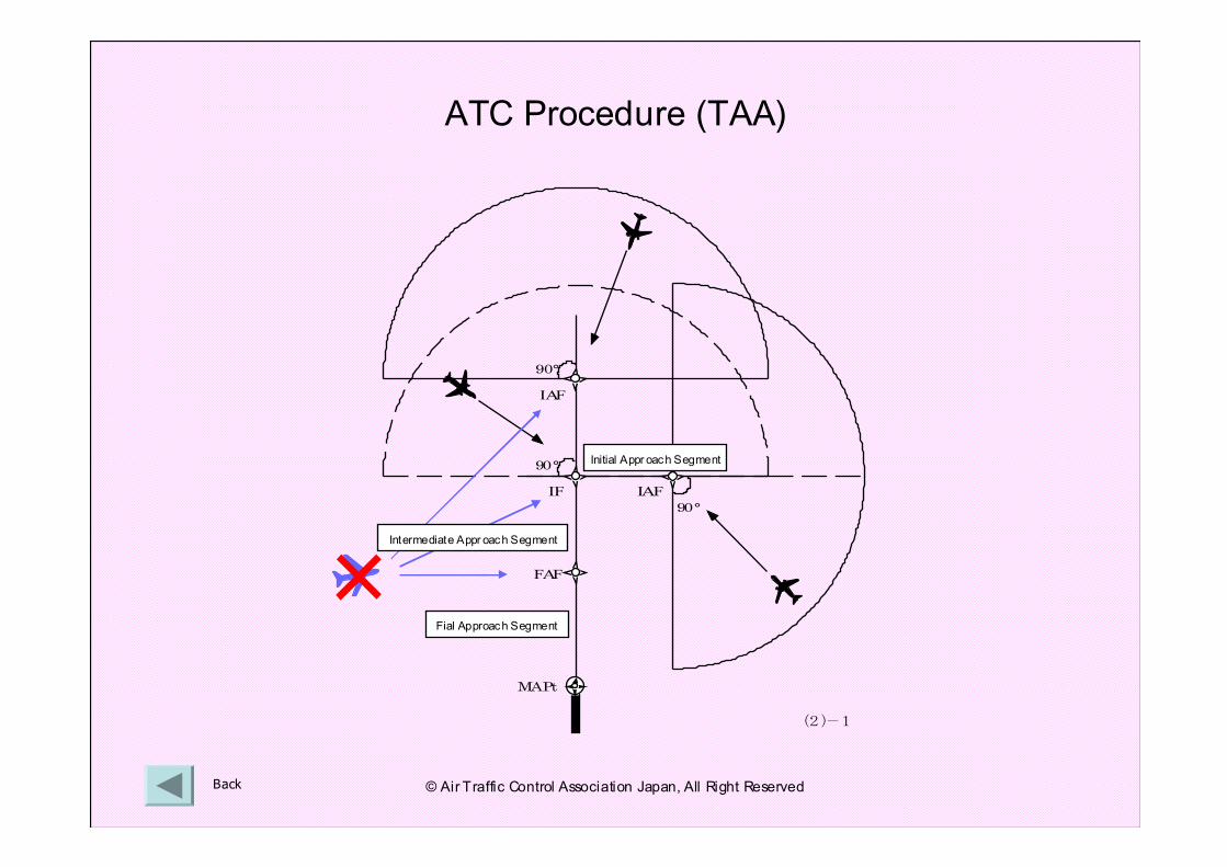
ATC Procedure (TAA)
中間進入セグメント
最終進入セグメント
初期進入セグメント
90°
90°
90°
IAF
IAF
IF
FAF
MAPt
(2)-1
Back
×Intermediate Appr oach Segment
Initial Appr oach Segment
Fial Approach Segment
© Air Traffic Control Association Japan, All Right Reserved
Back
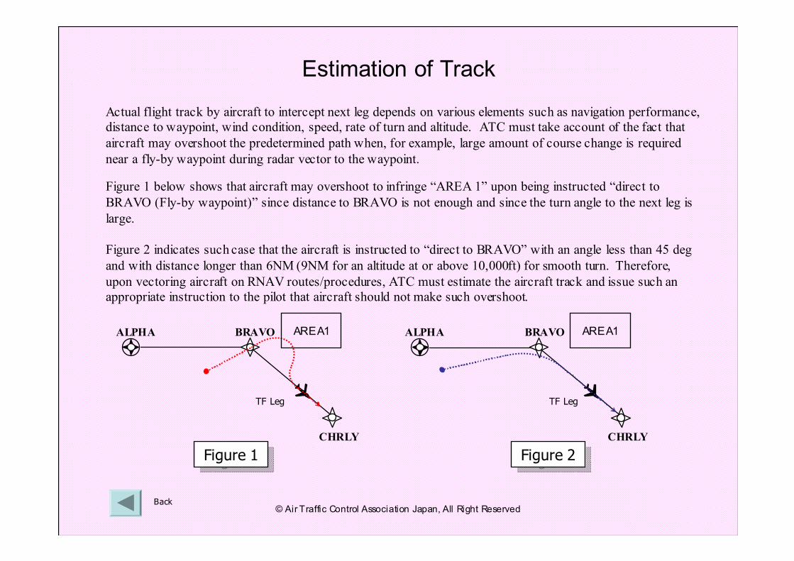
Actual flight track by aircraft to intercept next leg depends on various elements such as navigation performance,
distance to waypoint, wind condition, speed, rate of turn and altitude. ATC must take account of the fact that
aircraft may overshoot the predetermined path when, for example, large amount of course change is required
near a fly-by waypoint during radar vector to the waypoint.
Figure 1 below shows that aircraft may overshoot to infringe “AREA 1” upon being instructed “direct to
BRAVO (Fly-by waypoint)” since distance to BRAVO is not enough and since the turn angle to the next leg is
large.
Figure 2 indicates such case that the aircraft is instructed to “direct to BRAVO” with an angle less than 45 deg
and with distance longer than 6NM (9NM for an altitude at or above 10,000ft) for smooth turn. Therefore,
upon vectoring aircraft on RNAV routes/procedures, ATC must estimate the aircraft track and issue such an
appropriate instruction to the pilot that aircraft should not make such overshoot.
CHRLY
ALPHA BRAVO AREA1
Estimation of Track
Figure 1Figure 1 Figure 2Figure 2
ALPHA BRAVO
CHRLY
AREA1
TF Leg TF Leg
© Air Traffic Control Association Japan, All Right Reserved
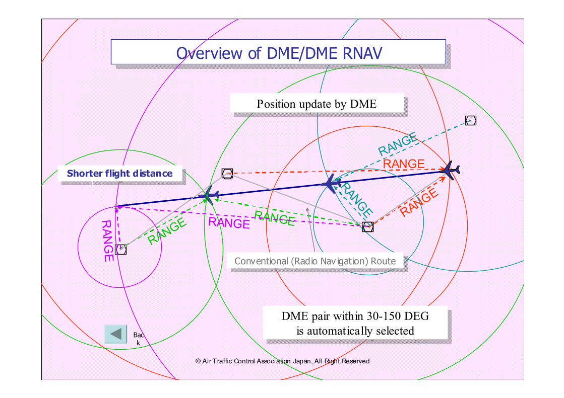
RANGE
RANGE
RANGE
RANGE
RANGE
RANGE
Overview of DME/DME RNAVOverview of DME/DME RNAV
RANGE
RANGE
DME pair within 30-150 DEG
is automatically selected
DME pair within 30-150 DEG
is automatically selected
Conventional (Radio Nav igation) RouteConventional (Radio Nav igation) Route
Shorter flight distanceShorter flight distance
Back
Position update by DMEPosition update by DME
© Air Traffic Control Association Japan, All Right Reserved
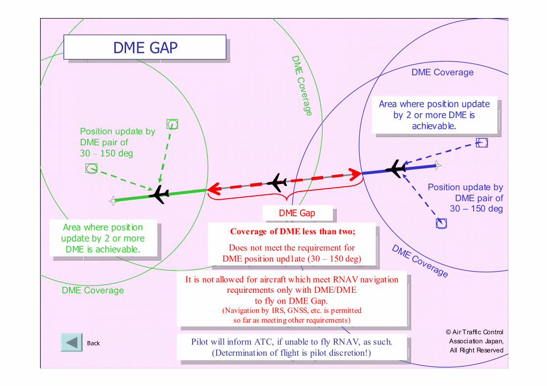
DME Coverage
Back
DME Coverage
DME Coverage
DME Coverage
Position update by
DME pair of
30 – 150 deg
Position update by
DME pair of 30 – 150 deg
Area where posit ion
update by 2 or more
DME is achievable.
Area where posit ion
update by 2 or more
DME is achievable.
Area where posit ion update
by 2 or more DME is
achievable.
Area where posit ion update
by 2 or more DME is
achievable.
DME GapDME Gap
Coverage of DME less than two;
Does not meet the requirement for
DME position upd1ate (30 – 150 deg)
Coverage of DME less than two;
Does not meet the requirement for
DME position upd1ate (30 – 150 deg)
DME GAP DME GAP
It is not allowed for aircraft which meet RNAV navigation
requirements only with DME/DME
to fly on DME Gap.(Navigation by IRS, GNSS, etc. is permitted
so far as meeting other requirements)
It is not allowed for aircraft which meet RNAV navigation
requirements only with DME/DME
to fly on DME Gap.(Navigation by IRS, GNSS, etc. is permitted
so far as meeting other requirements)
Pilot will inform ATC, if unable to fly RNAV, as such.
(Determination of flight is pilot discretion!)
Pilot will inform ATC, if unable to fly RNAV, as such.
(Determination of flight is pilot discretion!)
© Air Traffic Control
Association Japan,
All Right Reserved
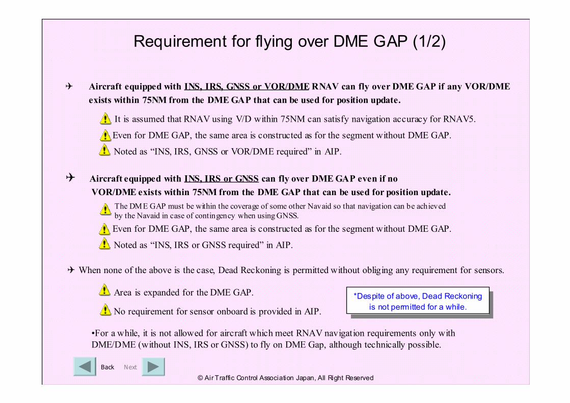
Requirement for flying over DME GAP (1/2)
NextBack
✈ Aircraft equipped with INS, IRS, GNSS or VOR/DMERNAV can fly over DME GAP if any VOR/DME
exists within 75NM from the DME GAP that can be used for position update.
It is assumed that RNAV using V/D within 75NM can satisfy navigation accuracy for RNAV5.
Even for DME GAP, the same area is constructed as for the segment without DME GAP.
Noted as “INS, IRS, GNSS or VOR/DME required” in AIP.
✈ Aircraft equipped with INS, IRS or GNSS can fly over DME GAP even if no
VOR/DME exists within 75NM from the DME GAP that can be used for position update.
✈ When none of the above is the case, Dead Reckoning is permitted without obliging any requirement for sensors.
Noted as “INS, IRS or GNSS required” in AIP.
No requirement for sensor onboard is provided in AIP.
Area is expanded for the DME GAP.
•For a while, it is not allowed for aircraft which meet RNAV navigation requirements only with
DME/DME (without INS, IRS or GNSS) to fly on DME Gap, although technically possible.
The DME GAP must be within the coverage of some other Navaid so that navigation can be achieved
by the Navaid in case of contingency when using GNSS.
Even for DME GAP, the same area is constructed as for the segment without DME GAP.
© Air Traffic Control Association Japan, All Right Reserved
*Despite of above, Dead Reckoning
is not permitted for a while.
*Despite of above, Dead Reckoning
is not permitted for a while.
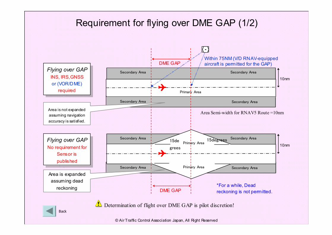
Requirement for flying over DME GAP (1/2)
Back
15de
grees
15degreesSecondary Area Secondary Area
Secondary Area Secondary AreaPrimary Area
Primary Area
DME GAP
Secondary Area Secondary Area
Secondary Area Secondary Area
Primary Area
DME GAP
Flying over GAP
INS, IRS,GNSS
or (VOR/DME)
required
Flying over GAP
INS, IRS,GNSS
or (VOR/DME)
required
Flying over GAP
No requirement for
Sensor is
published
Flying over GAP
No requirement for
Sensor is
published
Area is expanded
assuming dead
reckoning
Area is not expanded
assuming navigation
accuracy is satisfied.
Determination of flight over DME GAP is pilot discretion!
10nm
10nm
Area Semi-width for RNAV5 Route =10nm
*For a while, Dead
reckoning is not permitted.
Within 75NM (V/D RNAV-equipped aircraft is permitted for the GAP)
© Air Traffic Control Association Japan, All Right Reserved
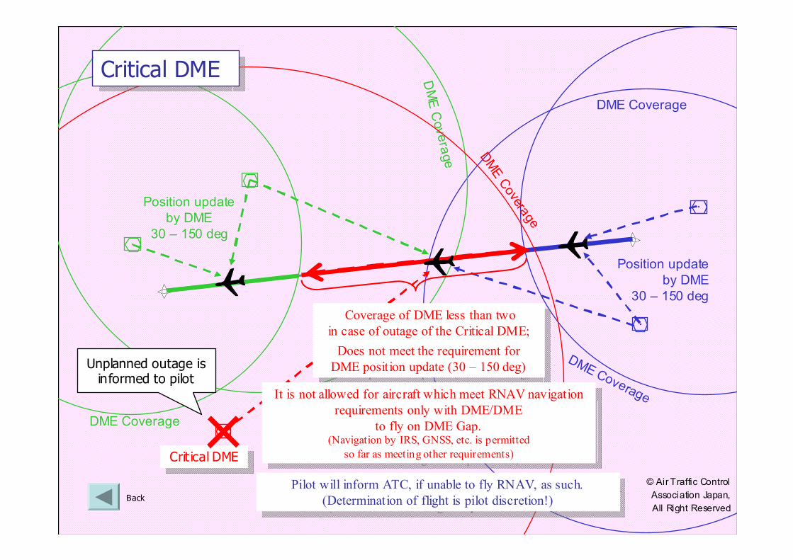
DME Coverage
Back
DME Coverage
DME Coverage
DME Coverage
Position update
by DME
30 – 150 deg
Position update
by DME
30 – 150 deg
Crit ical DMECrit ical DME
2局以上のDMEによる
位置更新可能範囲
2局以上のDMEによる
位置更新可能範囲
×
DME Covera
ge
Critical DMECritical DME
Coverage of DME less than two
in case of outage of the Critical DME;
Does not meet the requirement for
DME position update (30 – 150 deg)
Coverage of DME less than two
in case of outage of the Critical DME;
Does not meet the requirement for
DME position update (30 – 150 deg)Unplanned outage is informed to pilot
It is not allowed for aircraft which meet RNAV navigation
requirements only with DME/DME
to fly on DME Gap.(Navigation by IRS, GNSS, etc. is permitted
so far as meeting other requirements)
It is not allowed for aircraft which meet RNAV navigation
requirements only with DME/DME
to fly on DME Gap.(Navigation by IRS, GNSS, etc. is permitted
so far as meeting other requirements)
Pilot will inform ATC, if unable to fly RNAV, as such.
(Determination of flight is pilot discretion!)
Pilot will inform ATC, if unable to fly RNAV, as such.
(Determination of flight is pilot discretion!)
© Air Traffic Control
Association Japan,
All Right Reserved
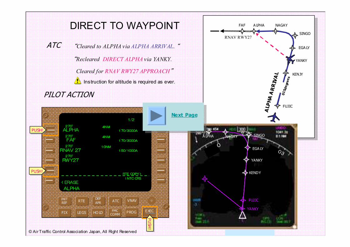
FAF A LPHA NAGAY
SINGO
FUJIC
KENJY
YANKY
ALPHA ARRIVAL
VNAVATCDEP
APRRTE
INITREF
FMCCOMM
HO LDLEGSFIX PROG
“Recleared DIRECT ALPHA via YANKY.
“Cleared to ALPHA via ALPHA ARRIVAL. “
015degre015degre015degre015degreeseseses
4N M4N M4N M4N MYANKYYANKYYANKYYANKY 210/4500A210/4500A210/4500A210/4500A
015degre015degre015degre015degreeseseses
4N M4N M4N M4N MEGALYEGALYEGALYEGALY 210/4500A210/4500A210/4500A210/4500A
015degre015degre015degre015degreeseseses
4N M4N M4N M4N M
SINGOSINGOSINGOSINGO 190/4500A190/4500A190/4500A190/4500A
270degre270degre270degre270degreeseseses
4N M4N M4N M4N M
ALPHAALPHAALPHAALPHA 170/3000A170/3000A170/3000A170/3000A
280degre280degre280degre280degre
eseseses4N M4N M4N M4N M
NAGAYNAGAYNAGAYNAGAY 170/3000A170/3000A170/3000A170/3000A
1/21/21/21/2
ALPHAALPHAALPHAALPHA
270270270270°°°° 4N M4N M4N M4N MALPHAALPHAALPHAALPHA 170/3000A170/3000A170/3000A170/3000A
270270270270°°°° 4N M4N M4N M4N MFAFFAFFAFFAF 170/3000A170/3000A170/3000A170/3000A
270270270270°°°° 10NM10NM10NM10NM
RNAVRNAVRNAVRNAV 27272727 150/1000A150/1000A150/1000A150/1000A
270270270270°°°°
RWY27RWY27RWY27RWY27
< RTE 2 LEGS RTE DATA >< RTE 2 LEGS RTE DATA >< RTE 2 LEGS RTE DATA >< RTE 2 LEGS RTE DATA >< ERASE< ERASE< ERASE< ERASEI NTC CRSI NTC CRSI NTC CRSI NTC CRS
RTE COPY >RTE COPY >RTE COPY >RTE COPY >PUSH!PUSH!
PUSH!PUSH!
DIRECT TO WAYPOINT
PILOT ACTION
ATC
EXECEXEC
PUSH!
PUSH!
O03
A LPHA
YANKY
KENDY
FUJIC
YANKY
Next Page
RNAV RWY27
015degrees
EGA LY
NAGAY SINGO
EGA LY
25
Cleared for RNAV RWY27 APPROACH”
Instruction for altitude is required as ever.
© Air Traffic Control Association Japan, All Right Reserved
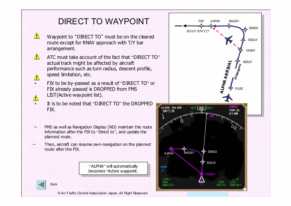
DIRECT TO WAYPOINT
- FMS as well as Navigation Display (ND) maintain the route information after the FIX to “Direct to”, and update the planned route.
- Then, aircraft can resume own-navigation on the planned route after the FIX.
“ALPHA”will automatically becomes “Active waypoint.
“ALPHA”will automatically becomes “Active waypoint.
• Waypoint to “DIRECT TO” must be on the c leared
route except for RNAV approach with T/Y bar
arrangement.
• ATC must take account of the fact that “DIRECT TO”
actual track might be affected by aircraft performance such as turn radius, descent profile,
speed limitat ion, etc.
• FIX to be by-passed as a result of “DIRECT TO” or
FIX already passed is DROPPED from FMS
LIST(Active waypoint list).
• It is to be noted that “DIRECT TO” the DROPPED
FIX.
Back
FAF A LPHA NAGAY
SINGO
FUJIC
KENJY
YANKY
ALPHA ARRIVAL
O03
A LPHA
YANKY
RNAV RWY27
015degrees
EGA LY
NAGAY SINGO
EGA LY
25
© Air Traffic Control Association Japan, All Right Reserved
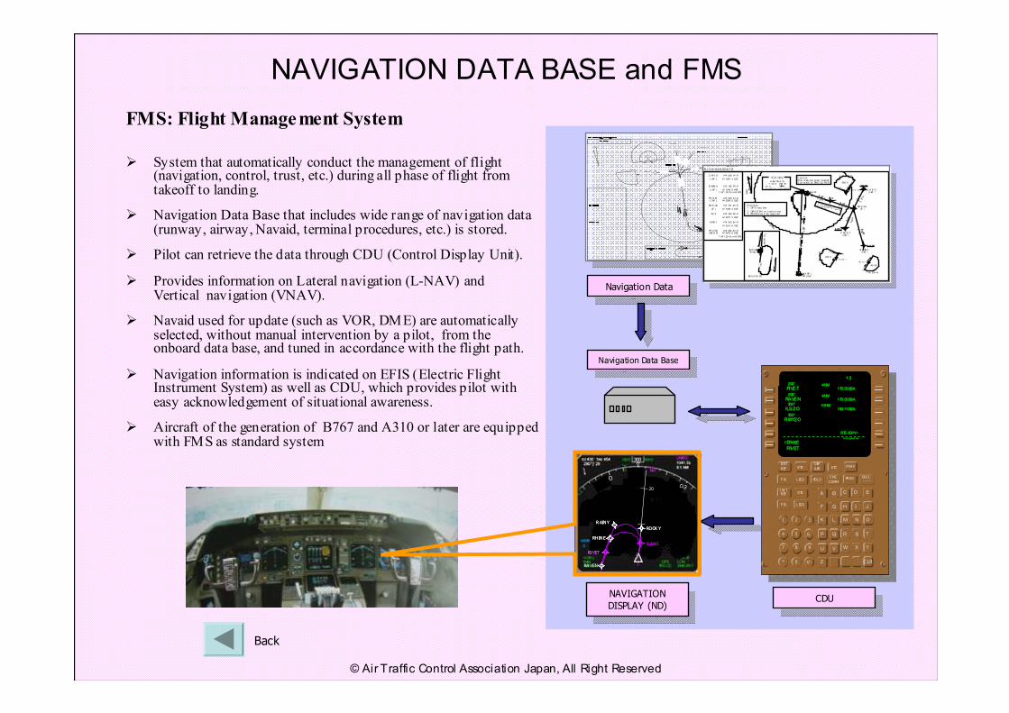
NAVIGATION DATA BASE and FMS
FMS: Flight Management System
� System that automatically conduct the management of flight (navigation, control, trust, etc.) during all phase of flight from takeoff to landing.
� Navigation Data Base that includes wide range of navigation data(runway, airway, Navaid, terminal procedures, etc.) is stored.
� Pilot can retrieve the data through CDU (Control Display Unit).
� Provides information on Lateral navigation (L-NAV) and Vertical navigation (VNAV).
� Navaid used for update (such as VOR, DME) are automatically selected, without manual intervention by a pilot, from the onboard data base, and tuned in accordance with the flight path.
� Navigation information is indicated on EFIS (Electric Flight Instrument System) as well as CDU, which provides pilot with easy acknowledgement of situational awareness.
� Aircraft of the generation of B767 and A310 or later are equipped with FMS as standard system
217 °
5.0nm
0 37 °
5. 0nm
00 4°
9.12nm
3 07 °5 .0n m
(M A HF )YH U KA
(M A HF )YH UK A
HWE 20DME
HWE R-194
HWE 27DME
MH A 40 00
HWE R-194
F AF
4 00 0
35 00
4 0 00
C aut i on:M ou nt ain ous ar ea l ocat ed2. 5n m N E of RWY 30 TH R
M A Pt
3 07 °5. 0nm
037°
217°
40 00
T AA 25N M
1 0NM
C HI Y O
( I AF )
E M IN A
( I AF )
FR O ST( I AF )
RO C CA
( IF )
FA F
MAP t
YH U KA(MA H F)
414 526. 14 N
14 1061 4. 22E
413 155. 78 N
14 1040 9. 44E1 53° / 18. 0n m H WE
413 636. 23 N14 0595 8. 02E
414 101. 23 N
14 1030 5. 91E
414 322. 39 N
14 0571 2. 46E
414 543. 54 N
14 0511 8. 79E
412 632. 43 N14 0472 8. 04E
1 94° / 20. 0n m H WE
Final
approac
h cour s
e
off set
10°
198°
RJ CH/HAKODAT E
VAR 8°56' W
2005
014o
194o
RO C CA(IF )
H AK OD A TE1 12. 3 HW E
CH- 70
41° 46’27”N/ 140° 49 '56 "E
VO R / DME
● ● ●●●
●
FR OS T
127°
037°
370 0
TAA 25NM
R em ar ks:1. GP S r equ ir ed.
2. DM E /D M E no t aut ho ri zed .3. RA DA R se rv ice r equ ir ed .
CH IY O
127°
217°
490 0
T AA 25N M
F RO S T(I AF )
E M IN A(I AF )
C H IY O(I AF )
RO CC A
Navigation Data BaseNavigation Data Base
Navigation DataNavigation Data
CDUCDUNAVIGATION
DISPLAY (ND)
NAVIGATION
DISPLAY (ND)
VNAVATCDEP
APRRTEINIT
REF
FMC
COMMHOL DL EGSF IX PROG
RTEI NI TREF
L EGSF IX
EXEC
1 2 3
4 5 6
7 8 9
* 0 +/ -
A B C D E
F G H I J
K L M N O
P Q R S T
U V W X Y
Z CLR
015015015015 °°°° 4NM4NM4NM4NMS US HIS US HIS US HIS US HI 210/4500A210/4500A210/4500A210/4500A
015015015015 °°°° 4NM4NM4NM4NMR OOKYR OOKYR OOKYR OOKY 210/4500A210/4500A210/4500A210/4500A
109109109109 °°°° 4NM4NM4NM4NMR AINYR AINYR AINYR AINY 190/4500A190/4500A190/4500A190/4500A
200200200200°°°° 4NM4NM4NM4NM
RIVE TRIVE TRIVE TRIVE T 170/ 3000A170/ 3000A170/ 3000A170/ 3000A
200200200200 °°°° 4NM4NM4NM4NMR HINER HINER HINER HINE 170/3000A170/3000A170/3000A170/3000A
1/ 21/ 21/ 21/ 2
015015015015°°°° 4NM4NM4NM4NMS US HIS US HIS US HIS US HI 210/4500A210/4500A210/4500A210/4500A
015015015015°°°° 4NM4NM4NM4NMR OOKYR OOKYR OOKYR OOKY 210/4500A210/4500A210/4500A210/4500A
109109109109°°°° 4NM4NM4NM4NMR AINYR AINYR AINYR AINY 190/4500A190/4500A190/4500A190/4500A
200200200200°°°° 4NM4NM4NM4NM
RIVE TRIVE TRIVE TRIVE T 170/ 3000A170/ 3000A170/ 3000A170/ 3000A
200200200200°°°° 4NM4NM4NM4NMR HINER HINER HINER HINE 170/3000A170/3000A170/3000A170/3000A
1/ 21/ 21/ 21/ 2
R IVETR IVETR IVETR IVET
200200200200°°°° 4NM4NM4NM4NMRIVE TRIVE TRIVE TRIVE T 170/3000A170/3000A170/3000A170/3000A
200200200200°°°° 4NM4NM4NM4NMRAVE NRAVE NRAVE NRAVE N 170/3000A170/3000A170/3000A170/3000A
200200200200°°°° 10NM10NM10NM10NMILS 20ILS 20ILS 20ILS 20 150/1000A150/1000A150/1000A150/1000A
200200200200°°°°
R WY2 0R WY2 0R WY2 0R WY2 0
< ERASE< ERASE< ERASE< ERASE
I NTC CRSI NTC CRSI NTC CRSI NTC CRS
RTE COPY >RTE COPY >RTE COPY >RTE COPY >
< ERASE< ERASE< ERASE< ERASE
I NTC CRSI NTC CRSI NTC CRSI NTC CRS
RTE COPY >RTE COPY >RTE COPY >RTE COPY >
VNAVATCDEP
APRRTEINIT
REF
FMC
COMMHOL DL EGSF IX PROG
RTEI NI TREF
L EGSF IX
EXEC
1 2 3
4 5 6
7 8 9
* 0 +/ -
1 2 3
4 5 6
1 2 31 2 3
4 5 64 5 6
7 8 9
* 0 +/ -
7 8 97 8 9
* 0 +/ -* 0 +/ -
A B C D E
F G H I J
K L M N O
P Q R S T
U V W X Y
Z CLR
A B C D EA B C D E
F G H I JF G H I J
K L M N OK L M N O
P Q R S TP Q R S T
U V W X YU V W X Y
Z CLRZ CLR
015015015015°°°° 4NM4NM4NM4NMS US HIS US HIS US HIS US HI 210/4500A210/4500A210/4500A210/4500A
015015015015°°°° 4NM4NM4NM4NMR OOKYR OOKYR OOKYR OOKY 210/4500A210/4500A210/4500A210/4500A
109109109109°°°° 4NM4NM4NM4NMR AINYR AINYR AINYR AINY 190/4500A190/4500A190/4500A190/4500A
200200200200°°°° 4NM4NM4NM4NM
RIVE TRIVE TRIVE TRIVE T 170/ 3000A170/ 3000A170/ 3000A170/ 3000A
200200200200°°°° 4NM4NM4NM4NMR HINER HINER HINER HINE 170/3000A170/3000A170/3000A170/3000A
1/ 21/ 21/ 21/ 2
R IVETR IVETR IVETR IVET
200200200200°°°° 4NM4NM4NM4NMRIVE TRIVE TRIVE TRIVE T 170/3000A170/3000A170/3000A170/3000A
200200200200°°°° 4NM4NM4NM4NMRAVE NRAVE NRAVE NRAVE N 170/3000A170/3000A170/3000A170/3000A
200200200200°°°° 10NM10NM10NM10NMILS 20ILS 20ILS 20ILS 20 150/1000A150/1000A150/1000A150/1000A
200200200200°°°°
R WY2 0R WY2 0R WY2 0R WY2 0
200200200200°°°° 4NM4NM4NM4NMRIVE TRIVE TRIVE TRIVE T 170/3000A170/3000A170/3000A170/3000A
200200200200°°°° 4NM4NM4NM4NMRAVE NRAVE NRAVE NRAVE N 170/3000A170/3000A170/3000A170/3000A
200200200200°°°° 10NM10NM10NM10NMILS 20ILS 20ILS 20ILS 20 150/1000A150/1000A150/1000A150/1000A
200200200200°°°°
R WY2 0R WY2 0R WY2 0R WY2 0
< ERASE< ERASE< ERASE< ERASE
I NTC CRSI NTC CRSI NTC CRSI NTC CRS
RTE COPY >RTE COPY >RTE COPY >RTE COPY >
< ERASE< ERASE< ERASE< ERASE
I NTC CRSI NTC CRSI NTC CRSI NTC CRS
RTE COPY >RTE COPY >RTE COPY >RTE COPY >
VNAVATCDEP
APRRTEINIT
REF
FMC
COMMHOL DL EGSF IX PROG
RTEI NI TREF
L EGSF IX
EXEC
1 2 3
4 5 6
7 8 9
* 0 +/ -
A B C D E
F G H I J
K L M N O
P Q R S T
U V W X Y
Z CLR
015015015015°°°° 4NM4NM4NM4NMS US HIS US HIS US HIS US HI 210/4500A210/4500A210/4500A210/4500A
015015015015°°°° 4NM4NM4NM4NMR OOKYR OOKYR OOKYR OOKY 210/4500A210/4500A210/4500A210/4500A
109109109109°°°° 4NM4NM4NM4NMR AINYR AINYR AINYR AINY 190/4500A190/4500A190/4500A190/4500A
200200200200°°°° 4NM4NM4NM4NM
RIVE TRIVE TRIVE TRIVE T 170/ 3000A170/ 3000A170/ 3000A170/ 3000A
200200200200°°°° 4NM4NM4NM4NMR HINER HINER HINER HINE 170/3000A170/3000A170/3000A170/3000A
1/ 21/ 21/ 21/ 2
R IVETR IVETR IVETR IVET
200200200200°°°° 4NM4NM4NM4NMRIVE TRIVE TRIVE TRIVE T 170/3000A170/3000A170/3000A170/3000A
200200200200°°°° 4NM4NM4NM4NMRAVE NRAVE NRAVE NRAVE N 170/3000A170/3000A170/3000A170/3000A
200200200200°°°° 10NM10NM10NM10NMILS 2 0ILS 2 0ILS 2 0ILS 2 0 150/1000A150/1000A150/1000A150/1000A
200200200200°°°°
R WY2 0R WY2 0R WY2 0R WY2 0
< ERASE< ERASE< ERASE< ERASE
I NTC CRSI NTC CRSI NTC CRSI NTC CRS
RTE COPY >RTE COPY >RTE COPY >RTE COPY >
< ERASE< ERASE< ERASE< ERASE
I NTC CRSI NTC CRSI NTC CRSI NTC CRS
RTE COPY >RTE COPY >RTE COPY >RTE COPY >
VNAVATCDEP
APRRTEINIT
REF
FMC
COMMHOL DL EGSF IX PROG
RTEI NI TREF
L EGSF IX
EXEC
1 2 3
4 5 6
7 8 9
* 0 +/ -
1 2 3
4 5 6
1 2 31 2 3
4 5 64 5 6
7 8 9
* 0 +/ -
7 8 97 8 9
* 0 +/ -* 0 +/ -
A B C D E
F G H I J
K L M N O
P Q R S T
U V W X Y
Z CLR
A B C D EA B C D E
F G H I JF G H I J
K L M N OK L M N O
P Q R S TP Q R S T
U V W X YU V W X Y
Z CLRZ CLR
015015015015°°°° 4NM4NM4NM4NMS US HIS US HIS US HIS US HI 210/4500A210/4500A210/4500A210/4500A
015015015015°°°° 4NM4NM4NM4NMR OOKYR OOKYR OOKYR OOKY 210/4500A210/4500A210/4500A210/4500A
109109109109°°°° 4NM4NM4NM4NMR AINYR AINYR AINYR AINY 190/4500A190/4500A190/4500A190/4500A
200200200200°°°° 4NM4NM4NM4NM
RIVE TRIVE TRIVE TRIVE T 170/ 3000A170/ 3000A170/ 3000A170/ 3000A
200200200200°°°° 4NM4NM4NM4NMR HINER HINER HINER HINE 170/3000A170/3000A170/3000A170/3000A
1/ 21/ 21/ 21/ 2
015015015015°°°° 4NM4NM4NM4NMS US HIS US HIS US HIS US HI 210/4500A210/4500A210/4500A210/4500A
015015015015°°°° 4NM4NM4NM4NMR OOKYR OOKYR OOKYR OOKY 210/4500A210/4500A210/4500A210/4500A
109109109109°°°° 4NM4NM4NM4NMR AINYR AINYR AINYR AINY 190/4500A190/4500A190/4500A190/4500A
200200200200°°°° 4NM4NM4NM4NM
RIVE TRIVE TRIVE TRIVE T 170/ 3000A170/ 3000A170/ 3000A170/ 3000A
200200200200°°°° 4NM4NM4NM4NMR HINER HINER HINER HINE 170/3000A170/3000A170/3000A170/3000A
1/ 21/ 21/ 21/ 2
R IVETR IVETR IVETR IVET
200200200200°°°° 4NM4NM4NM4NMRIVE TRIVE TRIVE TRIVE T 170/3000A170/3000A170/3000A170/3000A
200200200200°°°° 4NM4NM4NM4NMRAVE NRAVE NRAVE NRAVE N 170/3000A170/3000A170/3000A170/3000A
200200200200°°°° 10NM10NM10NM10NMILS 2 0ILS 2 0ILS 2 0ILS 2 0 150/1000A150/1000A150/1000A150/1000A
200200200200°°°°
R WY2 0R WY2 0R WY2 0R WY2 0
< ERASE< ERASE< ERASE< ERASE
I NTC CRSI NTC CRSI NTC CRSI NTC CRS
RTE COPY >RTE COPY >RTE COPY >RTE COPY >
< ERASE< ERASE< ERASE< ERASE
I NTC CRSI NTC CRSI NTC CRSI NTC CRS
RTE COPY >RTE COPY >RTE COPY >RTE COPY >
O03
20
RA VEN
RI VET
RH INE
R AINY
ROOK Y
SUSH I
RI VET
O03
20
RA VEN
RI VET
RH INE
R AINY
ROOK Y
SUSH I
RH INE
R AINY
ROOK Y
SUSH I
RI VET
Back
© Air Traffic Control Association Japan, All Right Reserved
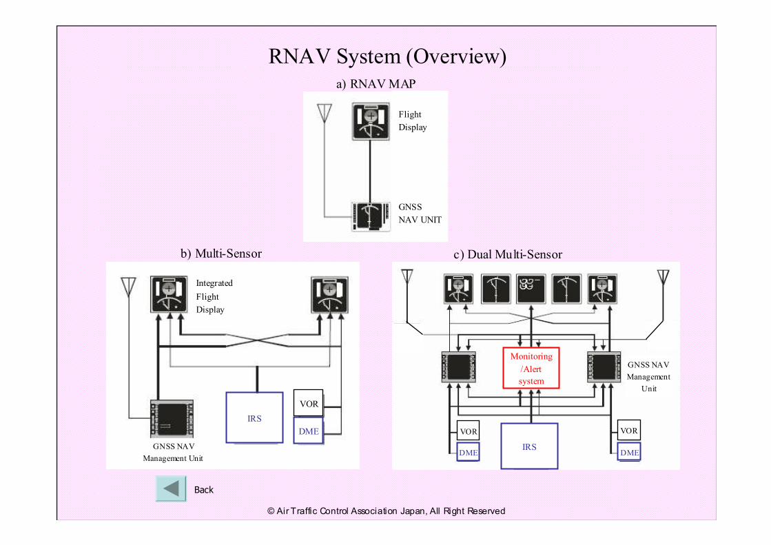
RNAV System (Overview)
Flight
Display
GNSS
NAV UNIT
IRS
Integrated
Flight
Display
GNSS NAV
Management Unit
IRS
Monitoring
/Alert
system
GNSS NAV
Management
Unit
a) RNAV MAP
b) Multi-Sensor c) Dual Multi-Sensor
DME
VOR
DME
VOR
DME
VOR
Back
© Air Traffic Control Association Japan, All Right Reserved
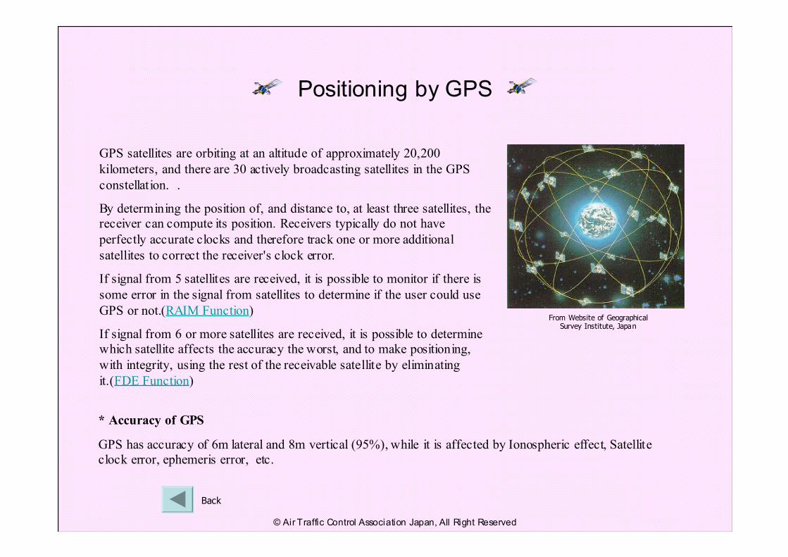
Positioning by GPS
GPS satellites are orbiting at an altitude of approximately 20,200
kilometers, and there are 30 actively broadcasting satellites in the GPS
constellation. .
By determining the position of, and distance to, at least three satellites, the
receiver can compute its position. Receivers typically do not have
perfectly accurate clocks and therefore track one or more additional
satellites to correct the receiver's clock error.
If signal from 5 satellites are received, it is possible to monitor if there is
some error in the signal from satellites to determine if the user could use
GPS or not.(RAIM Function)
If signal from 6 or more satellites are received, it is possible to determine
which satellite affects the accuracy the worst, and to make positioning,
with integrity, using the rest of the receivable satellite by eliminating
it.(FDE Function)
From Website of Geographical Survey Institute, Japan
* Accuracy of GPS
GPS has accuracy of 6m lateral and 8m vertical (95%), while it is affected by Ionospheric effect, Satellite
clock error, ephemeris error, etc.
Back
© Air Traffic Control Association Japan, All Right Reserved
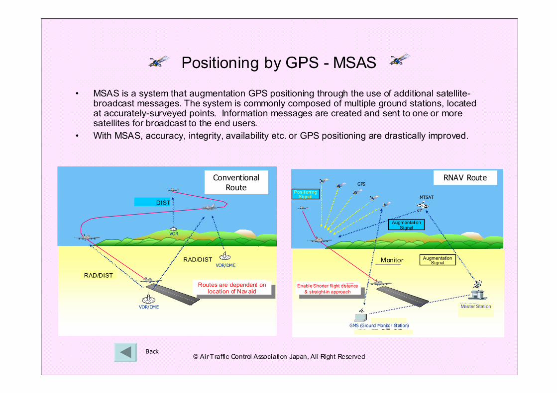
• MSAS is a system that augmentation GPS positioning through the use of additional satellite-broadcast messages. The system is commonly composed of multiple ground stations, located at accurately-surveyed points. Information messages are created and sent to one or more satellites for broadcast to the end users.
• With MSAS, accuracy, integrity, availability etc. or GPS positioning are drastically improved.
Positioning by GPS - MSAS
VOR
VOR/DME
VOR/DME
方位情報
方位/距離情報
方位/距離情報
経路=NAVAIDS設置位置の制約経路=NAVAIDS設置位置の制約
VOR
VOR/DME
VOR/DME
方位情報
方位/距離情報
方位/距離情報
VOR
VOR/DME
VOR/DME
方位情報
方位/距離情報
方位/距離情報
経路=NAVAIDS設置位置の制約経路=NAVAIDS設置位置の制約
Conventional
Route
Back
RAD/DIST
RAD/DIST
DIST
Routes are dependent on location of Nav aid
Routes are dependent on location of Nav aid
監視局GMS (Ground Monitor Station)
MTSAT
GPS
航空衛星センター
東京、福岡、那覇、千歳
神戸、常陸太田
補強信号
補強信号
モニター
測位信号
経路短縮 & 直線進入の実現経路短縮 & 直線進入の実現
監視局GMS (Ground Monitor Station)
MTSAT
GPS
航空衛星センター
東京、福岡、那覇、千歳
神戸、常陸太田
補強信号
補強信号
モニター
測位信号
経路短縮 & 直線進入の実現経路短縮 & 直線進入の実現
RNAV Route
Enable Shorter flight distance
& straight-in approach
Enable Shorter flight distance
& straight-in approach
Monitor
Augmentation Signal
PositioningSignal
Augmentation Signal
Master Station
© Air Traffic Control Association Japan, All Right Reserved
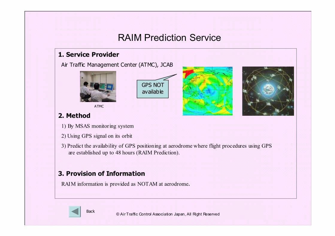
1. Service Provider
Air Traffic Management Center (ATMC), JCAB
2. Method
1) By MSAS monitoring system
2) Using GPS signal on its orbit
3) Predict the availability of GPS positioning at aerodrome where flight procedures using GPS
are established up to 48 hours (RAIM Prediction).
3. Provision of Information
RAIM information is provided as NOTAM at aerodrome.
RAIM Prediction Service
Back
ATMC
GPS NOT
available
© Air Traffic Control Association Japan, All Right Reserved
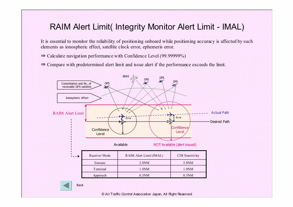
RAIM Alert Limit( Integrity Monitor Alert Limit - IMAL)
It is essential to monitor the reliability of positioning onboard while positioning accuracy is affected by such
elements as ionospheric effect, satellite clock error, ephemeris error.
⇒ Calculate navigation performance with Confidence Level (99.99999%)
⇒ Compare with predetermined alert limit and issue alert if the performance exceeds the limit.
0.3NM0.3NMApproach
1.0NM1.0NMTerminal
5.0NM2.0NMEnroute
CDI SensitivityRAIM Alert Limit (IMAL)Receiver Mode
Actual Path
Desired Path
ErrorError
RAIM Alert Limit
Available NOT Available (alert issued)
Confidence Level
Confidence Level
SBAS
GPSConstellation and No. of receivable GPS satellite
Ionospheric effect
GPS
GPS
GPS
Back
© Air Traffic Control Association Japan, All Right Reserved
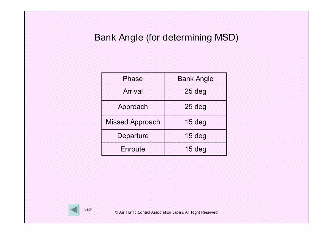
25 degArrival
15 degMissed Approach
15 degEnroute
15 degDeparture
25 degApproach
Bank AnglePhase
Bank Angle (for determining MSD)
Back© Air Traffic Control Association Japan, All Right Reserved
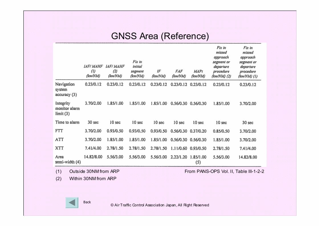
Back
GNSS Area (Reference)
(1) Outside 30NM from ARP
(2) Within 30NM from ARP
From PANS-OPS Vol. II, Table III-1-2-2
© Air Traffic Control Association Japan, All Right Reserved
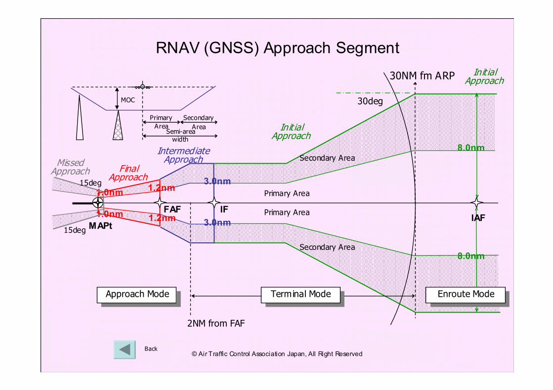
MAPt
1.0nm
1.0nmFAF
1.2nm
1.2nm
30deg
3.0nm
3.0nm
8.0nm
30NM fm ARP
IF
8.0nm
IAF
Approach ModeApproach Mode Enroute ModeEnroute Mode
2NM from FAF
Primary Area
Primary Area
Secondary Area
Secondary Area
RNAV (GNSS) Approach Segment
Back
Primary
Area
Secondary
AreaSemi-area width
MOC
15deg
15deg
Terminal ModeTerminal Mode
Final Approach
Intermediate Approach
Init ial Approach
Missed Approach
Init ial Approach
© Air Traffic Control Association Japan, All Right Reserved
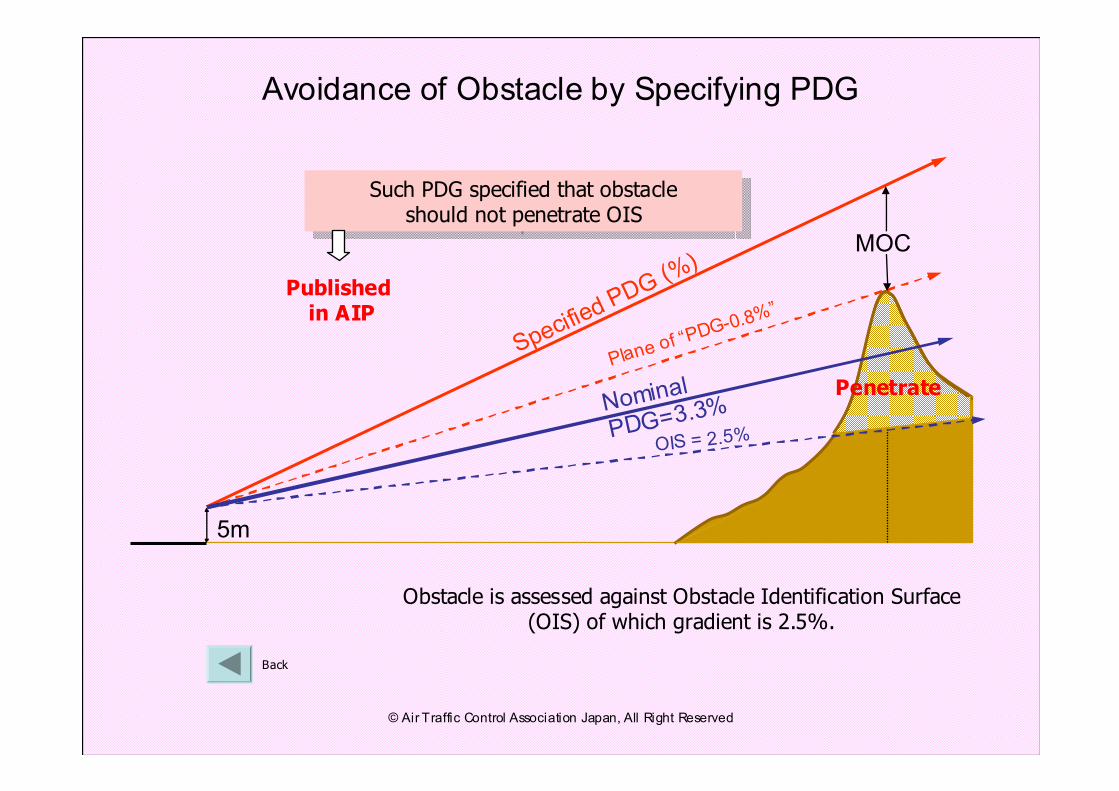
Nominal
PDG=3.3%
MOC
Specified PDG (%)
Plane of
“PDG-0.
8%”
5m
Avoidance of Obstacle by Specifying PDG
OIS = 2.5%
Penetrate
Back
Obstacle is assessed against Obstacle Identification Surface (OIS) of which gradient is 2.5%.
Such PDG specified that obstacle should not penetrate OIS
Such PDG specified that obstacle should not penetrate OIS
Publishedin AIP
© Air Traffic Control Association Japan, All Right Reserved
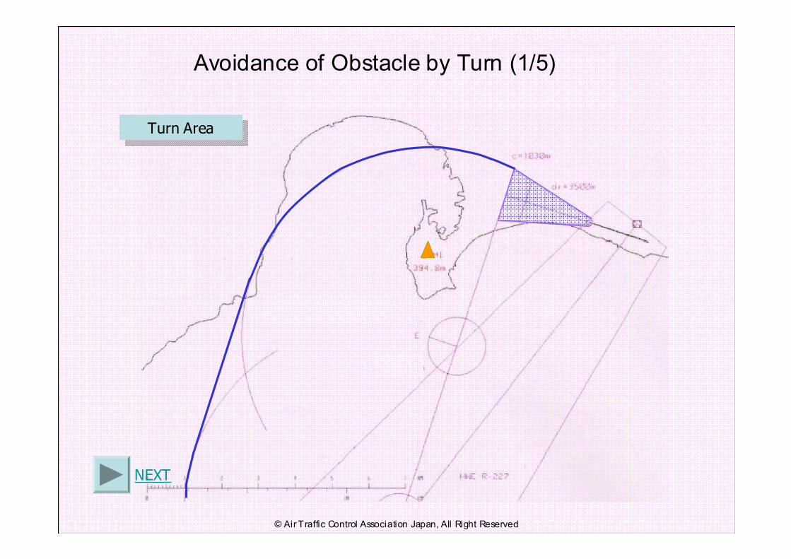
Avoidance of Obstacle by Turn (1/5)
NEXT
Turn AreaTurn Area
© Air Traffic Control Association Japan, All Right Reserved
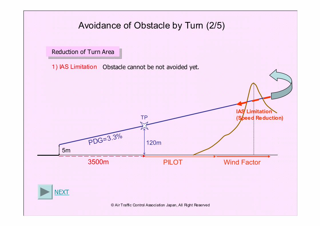
PDG=3.3%
5m
IAS Limitation
(Speed Reduction)TP
120m
PILOT Wind Factor
Avoidance of Obstacle by Turn (2/5)
NEXT
Reduction of Turn AreaReduction of Turn Area
Obstacle cannot be not avoided yet.1) IAS Limitation
3500m
© Air Traffic Control Association Japan, All Right Reserved
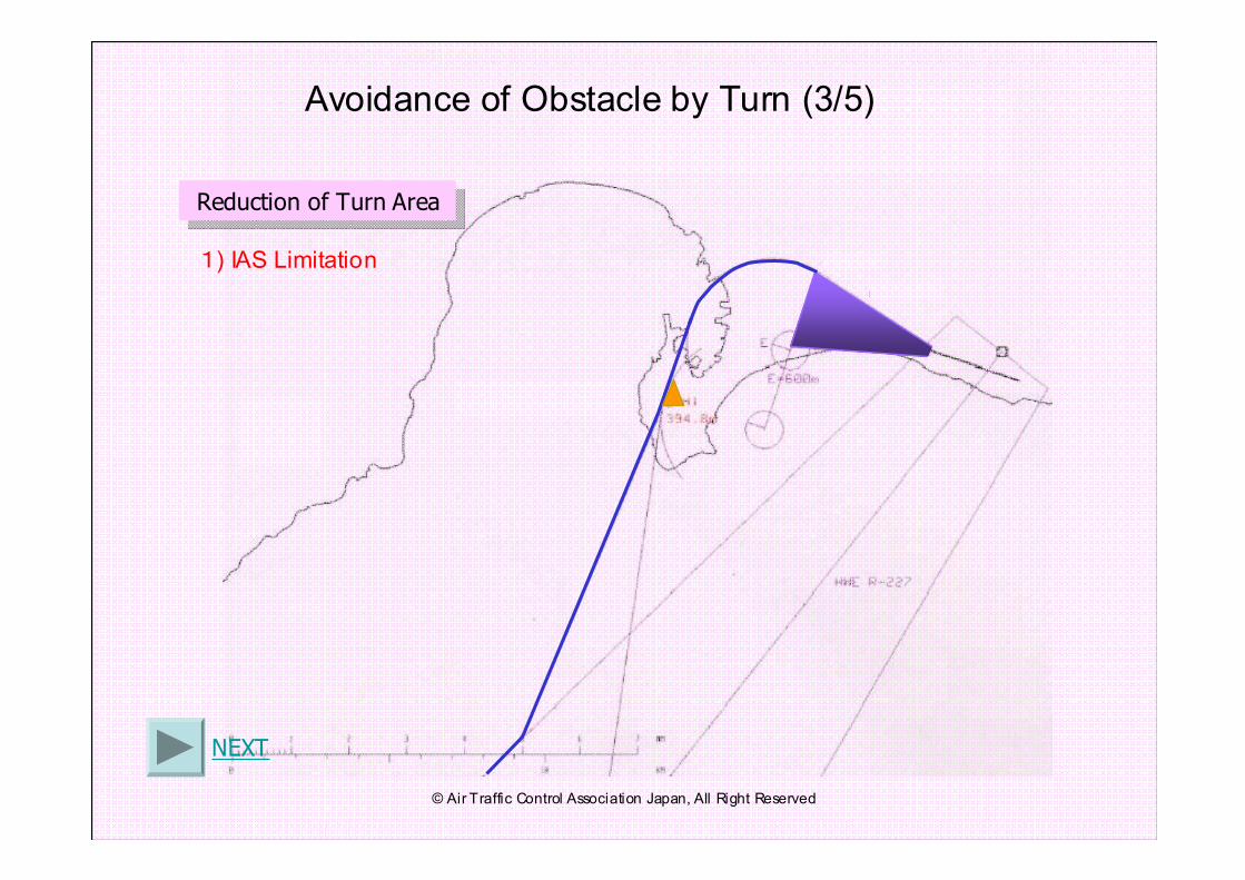
Avoidance of Obstacle by Turn (3/5)
NEXT
Reduction of Turn AreaReduction of Turn Area
1) IAS Limitation
© Air Traffic Control Association Japan, All Right Reserved
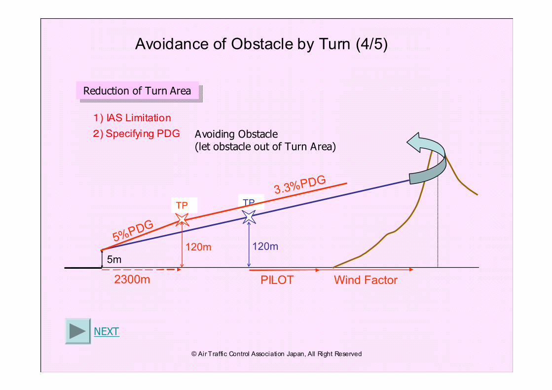
5m
120m
TP
120m5%PDG
2300m
3.3%PDG
PILOT Wind Factor
TP
Avoidance of Obstacle by Turn (4/5)
NEXT
2) Specifying PDG Avoiding Obstacle(let obstacle out of Turn Area)
Reduction of Turn AreaReduction of Turn Area
1) IAS Limitation
© Air Traffic Control Association Japan, All Right Reserved
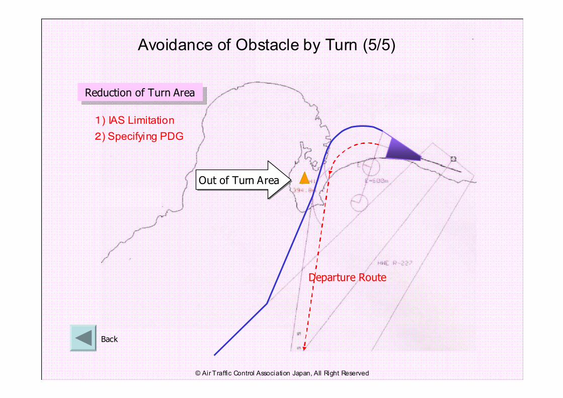
Avoidance of Obstacle by Turn (5/5)
Back
Departure Route
Out of Turn AreaOut of Turn Area
2) Specifying PDG
Reduction of Turn AreaReduction of Turn Area
1) IAS Limitation
© Air Traffic Control Association Japan, All Right Reserved
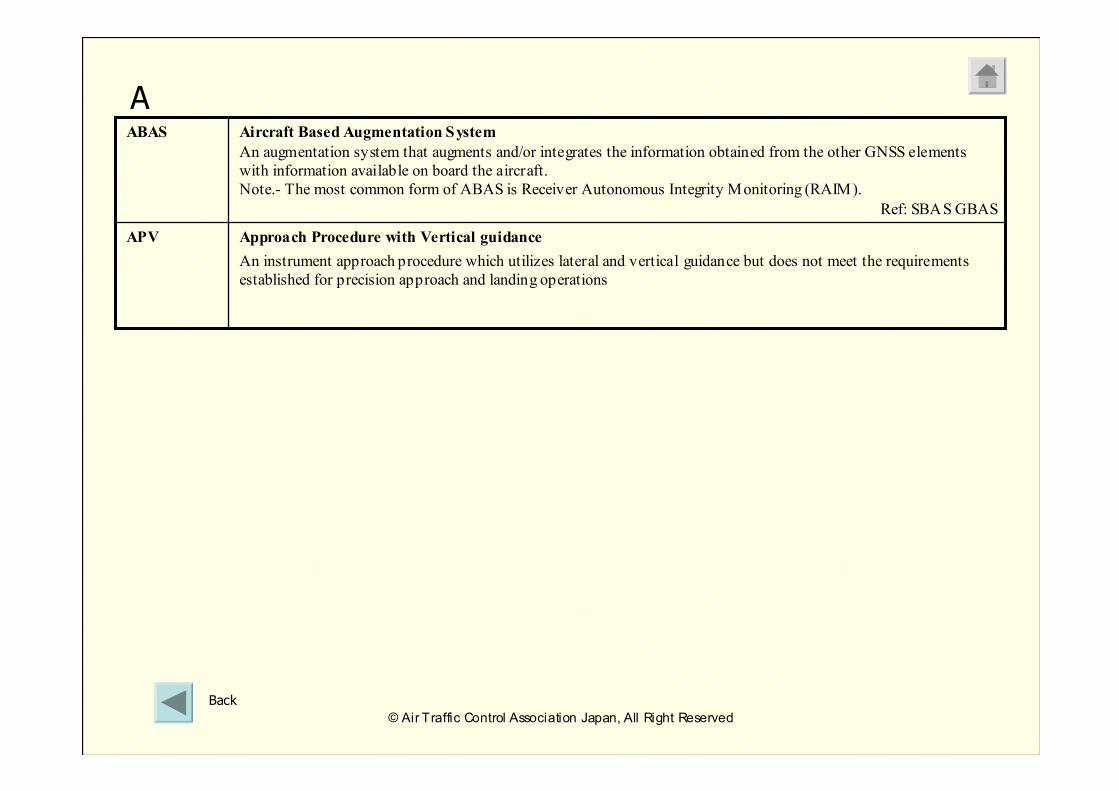
Approach Procedure with Vertical guidance
An instrument approach procedure which utilizes lateral and vertical guidance but does not meet the requirements
established for precision approach and landing operations
APV
Aircraft Based Augmentation System
An augmentation system that augments and/or integrates the information obtained from the other GNSS elements
with information available on board the aircraft.
Note.- The most common form of ABAS is Receiver Autonomous Integrity Monitoring (RAIM).
Ref: SBAS GBAS
ABAS
A
Back
© Air Traffic Control Association Japan, All Right Reserved
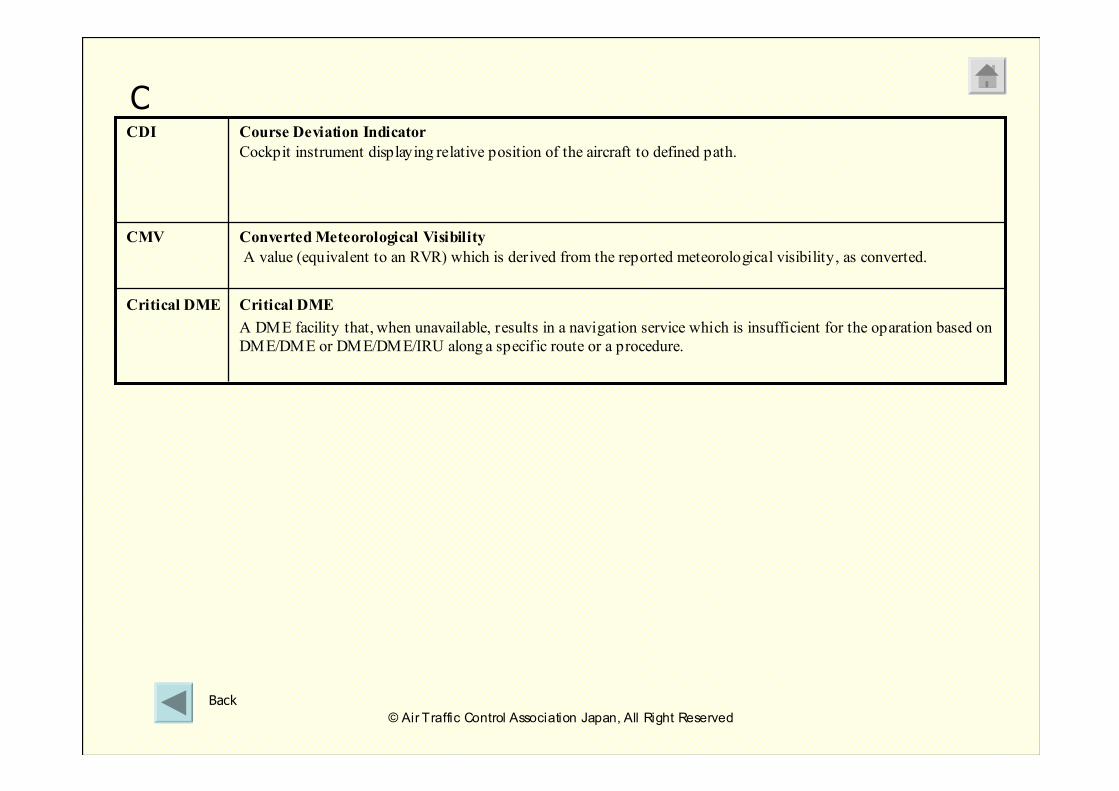
Critical DME
A DME facility that, when unavailable, results in a navigation service which is insufficient for the oparation based on
DME/DME or DME/DME/IRU along a specific route or a procedure.
Critical DME
Converted Meteorological Visibility
A value (equivalent to an RVR) which is derived from the reported meteorological visibility, as converted.
CMV
Course Deviation Indicator
Cockpit instrument displaying relative position of the aircraft to defined path.
CDI
C
Back
© Air Traffic Control Association Japan, All Right Reserved
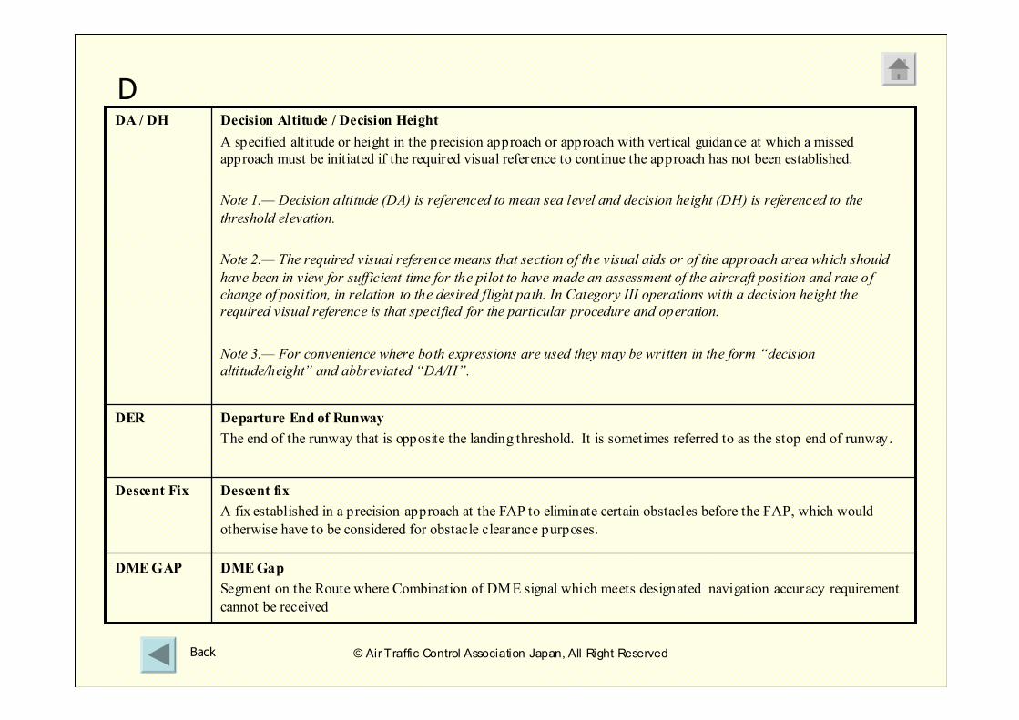
DME Gap
Segment on the Route where Combination of DME signal which meets designated navigation accuracy requirement
cannot be received
DME GAP
Departure End of Runway
The end of the runway that is opposite the landing threshold. It is sometimes referred to as the stop end of runway.
DER
Decision Altitude / Decision Height
A specified altitude or height in the precision approach or approach with vertical guidance at which a missed
approach must be initiated if the required visual reference to continue the approach has not been established.
Note 1.— Decision altitude (DA) is referenced to mean sea level and decision height (DH) is referenced to the
threshold elevation.
Note 2.— The required visual reference means that section of the visual aids or of the approach area which should
have been in view for sufficient time for the pilot to have made an assessment of the aircraft position and rate of
change of position, in relation to the desired flight path. In Category III operations with a decision height the
required visual reference is that specified for the particular procedure and operation.
Note 3.— For convenience where both expressions are used they may be written in the form “decision
altitude/height” and abbreviated “DA/H”.
DA / DH
Descent fix
A fix established in a precision approach at the FAP to eliminate certain obstacles before the FAP, which would
otherwise have to be considered for obstacle clearance purposes.
Descent Fix
D
Back © Air Traffic Control Association Japan, All Right Reserved
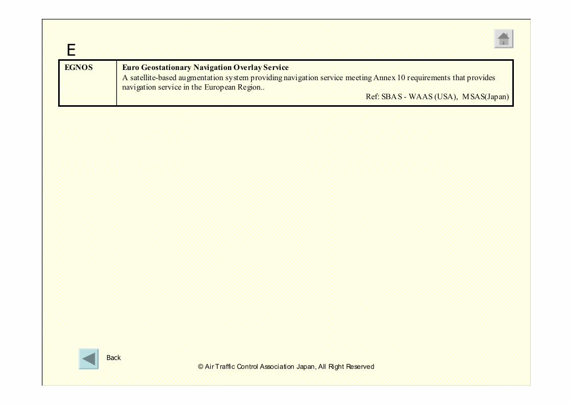
Euro Geostationary Navigation Overlay Service
A satellite-based augmentation system providing navigation service meeting Annex 10 requirements that provides
navigation service in the European Region..
Ref: SBAS - WAAS (USA), MSAS(Japan)
EGNOS
E
Back
© Air Traffic Control Association Japan, All Right Reserved
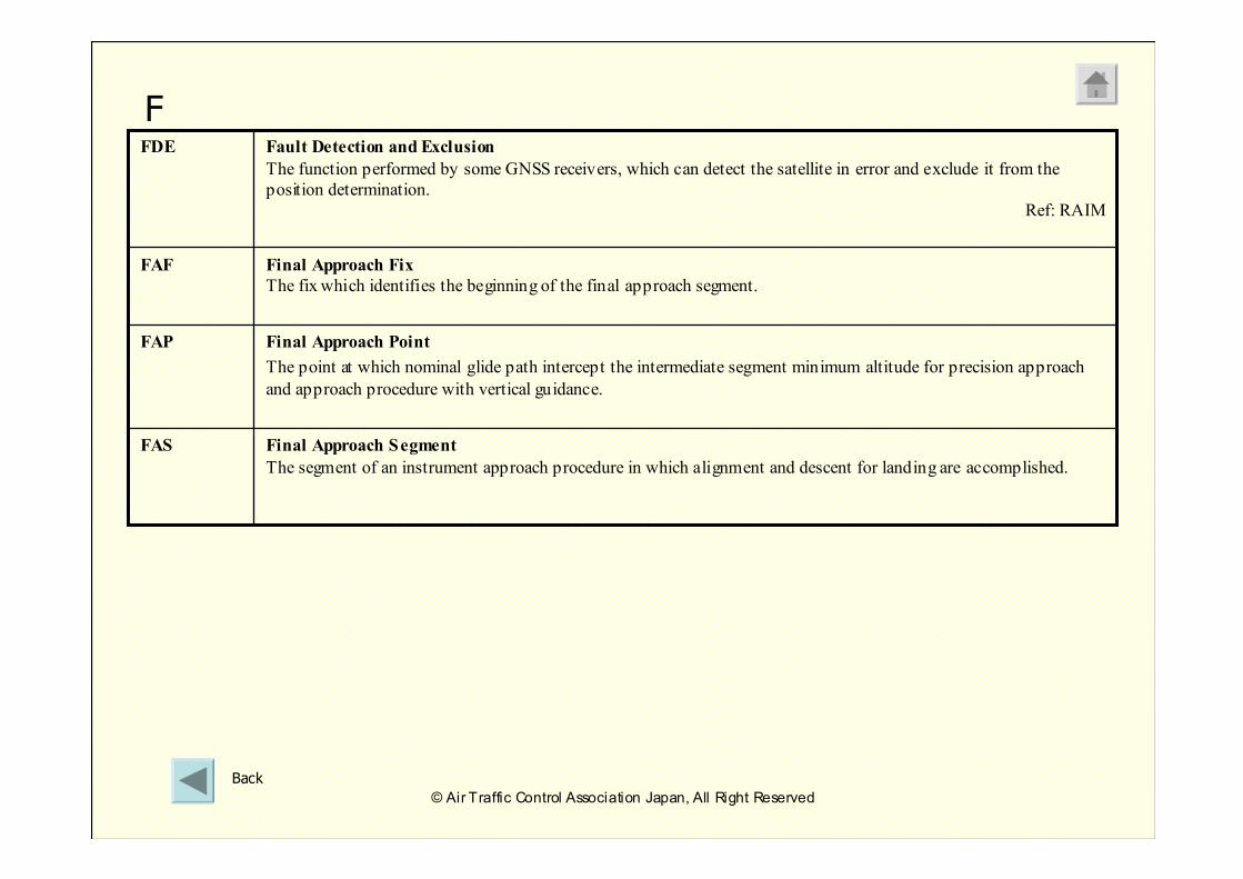
Final Approach Fix
The fix which identifies the beginning of the final approach segment.
FAF
Final Approach Segment
The segment of an instrument approach procedure in which alignment and descent for landing are accomplished.
FAS
Fault Detection and Exclusion
The function performed by some GNSS receivers, which can detect the satellite in error and exclude it from the
position determination.
Ref: RAIM
FDE
Final Approach Point
The point at which nominal glide path intercept the intermediate segment minimum altitude for precision approach
and approach procedure with vertical guidance.
FAP
F
Back
© Air Traffic Control Association Japan, All Right Reserved
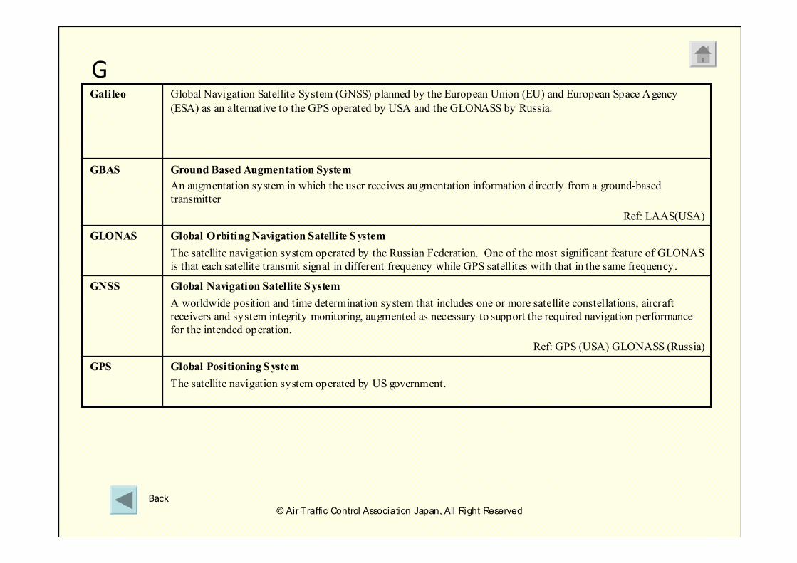
Ground Based Augmentation System
An augmentation system in which the user receives augmentation information directly from a ground-based
transmitter
Ref: LAAS(USA)
GBAS
Global Orbiting Navigation Satellite System
The satellite navigation system operated by the Russian Federation. One of the most significant feature of GLONAS
is that each satellite transmit signal in different frequency while GPS satellites with that in the same frequency.
GLONAS
Global Positioning System
The satellite navigation system operated by US government.
GPS
Global Navigation Satellite System
A worldwide position and time determination system that includes one or more satellite constellations, aircraft
receivers and system integrity monitoring, augmented as necessary to support the required navigation performance
for the intended operation.
Ref: GPS (USA) GLONASS (Russia)
GNSS
Global Navigation Satellite System (GNSS) planned by the European Union (EU) and European Space Agency
(ESA) as an alternative to the GPS operated by USA and the GLONASS by Russia.
Galileo
G
Back
© Air Traffic Control Association Japan, All Right Reserved
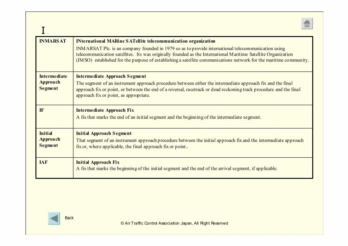
Initial Approach Segment
That segment of an instrument approach procedure between the initial approach fix and the intermediate approach
fix or, where applicable, the final approach fix or point..
Initial
Approach
Segment
Intermediate Approach Segment
The segment of an instrument approach procedure between either the intermediate approach fix and the final
approach fix or point, or between the end of a reversal, racetrack or dead reckoning track procedure and the final
approach fix or point, as appropriate.
Intermediate
Approach
Segment
Intermediate Approach Fix
A fix that marks the end of an initial segment and the beginning of the intermediate segment.
IF
INternational MARine SATellite telecommunication organization
INMARSAT Plc. is an company founded in 1979 so as to provide international telecommunication using
telecommunication satellites. Its was originally founded as the International Maritime Satellite Organization
(IMSO) established for the purpose of establishing a satellite communications network for the maritime community.
INMARSAT
Initial Approach Fix
A fix that marks the beginning of the initial segment and the end of the arrival segment, if applicable.
IAF
I
Back
© Air Traffic Control Association Japan, All Right Reserved
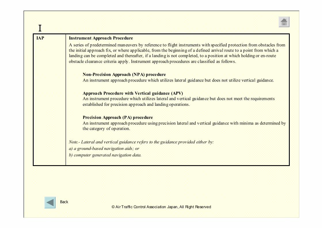
Instrument Approach Procedure
A series of predetermined maneuvers by reference to flight instruments with specified protection from obstacles from
the initial approach fix, or where applicable, from the beginning of a defined arrival route to a point from which a
landing can be completed and thereafter, if a landing is not completed, to a position at which holding or en-route
obstacle clearance criteria apply. Instrument approach procedures are classified as follows.
Non-Precision Approach (NPA) procedure
An instrument approach procedure which utilizes lateral guidance but does not utilize vertical guidance.
Approach Procedure with Vertical guidance (APV)
An instrument procedure which utilizes lateral and vertical guidance but does not meet the requirements
established for precision approach and landing operations.
Precision Approach (PA) procedure
An instrument approach procedure using precision lateral and vertical guidance with minima as determined by
the category of operation.
Note.- Lateral and vertical guidance refers to the guidance provided either by:
a) a ground-based navigation aids; or
b) computer generated navigation data.
IAP
I
Back
© Air Traffic Control Association Japan, All Right Reserved
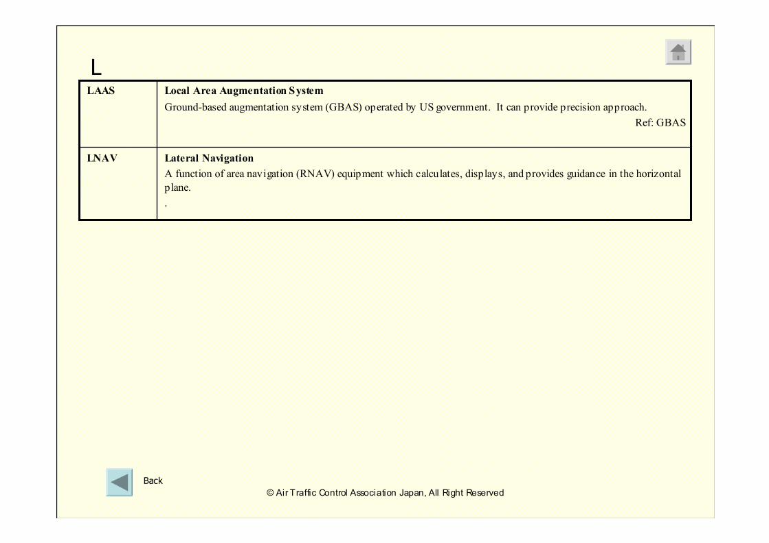
Lateral Navigation
A function of area navigation (RNAV) equipment which calculates, displays, and provides guidance in the horizontal
plane.
.
LNAV
Local Area Augmentation System
Ground-based augmentation system (GBAS) operated by US government. It can provide precision approach.
Ref: GBAS
LAAS
L
Back
© Air Traffic Control Association Japan, All Right Reserved
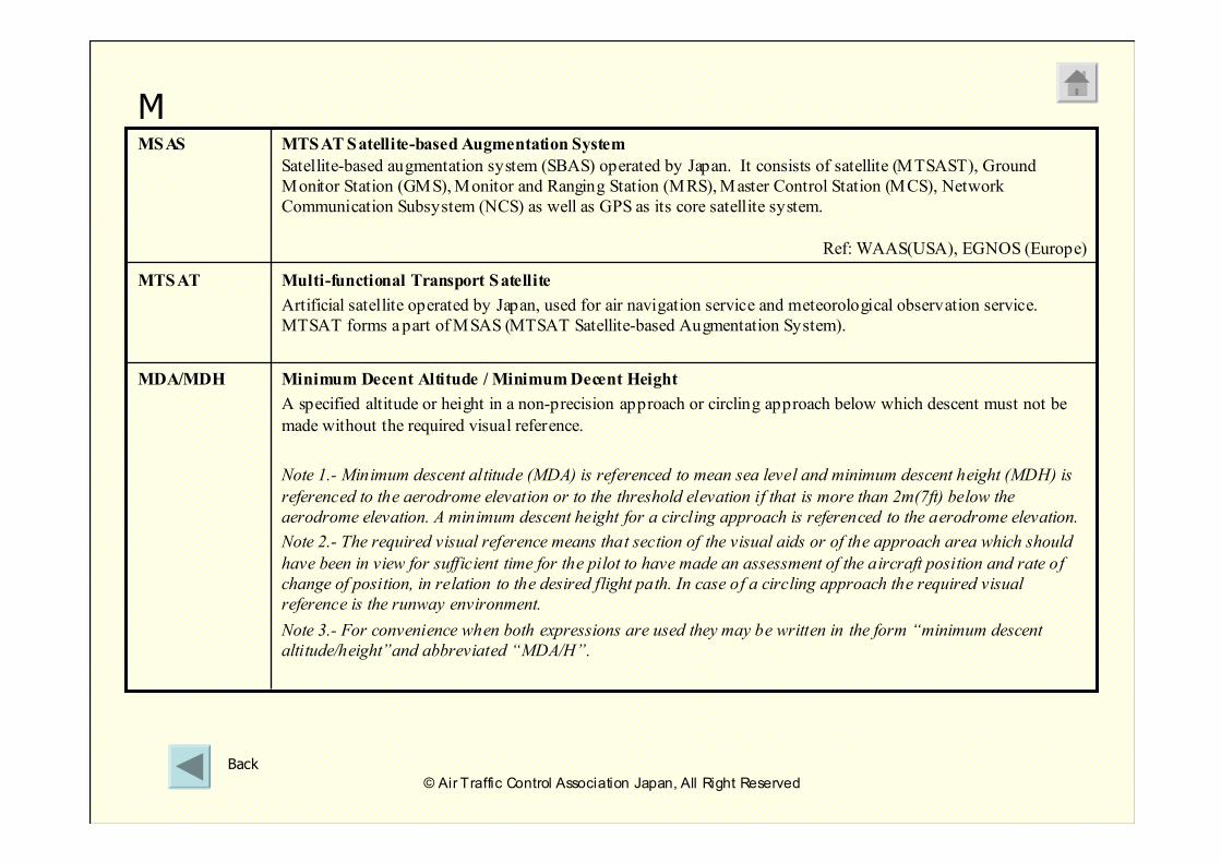
Minimum Decent Altitude / MinimumDecent Height
A specified altitude or height in a non-precision approach or circling approach below which descent must not be
made without the required visual reference.
Note 1.- Minimum descent altitude (MDA) is referenced to mean sea level and minimum descent height (MDH) is
referenced to the aerodrome elevation or to the threshold elevation if that is more than 2m(7ft) below the
aerodrome elevation. A minimum descent height for a circling approach is referenced to the aerodrome elevation.
Note 2.- The required visual reference means that section of the visual aids or of the approach area which should
have been in view for sufficient time for the pilot to have made an assessment of the aircraft position and rate of
change of position, in relation to the desired flight path. In case of a circling approach the required visual
reference is the runway environment.
Note 3.- For convenience when both expressions are used they may be written in the form “minimum descent
altitude/height”and abbreviated “MDA/H”.
MDA/MDH
Multi-functional Transport Satellite
Artificial satellite operated by Japan, used for air navigation service and meteorological observation service.
MTSAT forms a part of MSAS (MTSAT Satellite-based Augmentation System).
MTSAT
MTSATSatellite-based Augmentation System
Satellite-based augmentation system (SBAS) operated by Japan. It consists of satellite (MTSAST), Ground
Monitor Station (GMS), Monitor and Ranging Station (MRS), Master Control Station (MCS), Network
Communication Subsystem (NCS) as well as GPS as its core satellite system.
Ref: WAAS(USA), EGNOS (Europe)
MSAS
M
Back
© Air Traffic Control Association Japan, All Right Reserved
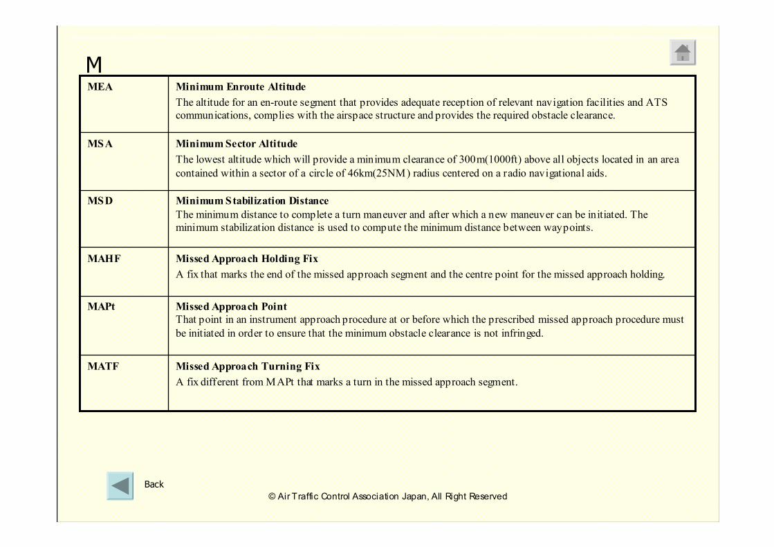
Minimum Enroute Altitude
The altitude for an en-route segment that provides adequate reception of relevant navigation facilities and ATS
communications, complies with the airspace structure and provides the required obstacle clearance.
MEA
Minimum Sector Altitude
The lowest altitude which will provide a minimum clearance of 300m(1000ft) above all objects located in an area
contained within a sector of a circle of 46km(25NM) radius centered on a radio navigational aids.
MSA
Missed Approach Point
That point in an instrument approach procedure at or before which the prescribed missed approach procedure must
be initiated in order to ensure that the minimum obstacle clearance is not infringed.
MAPt
Minimum Stabilization Distance
The minimum distance to complete a turn maneuver and after which a new maneuver can be initiated. The
minimum stabilization distance is used to compute the minimum distance between waypoints.
MSD
Missed Approach Turning Fix
A fix different from MAPt that marks a turn in the missed approach segment.
MATF
Missed Approach Holding Fix
A fix that marks the end of the missed approach segment and the centre point for the missed approach holding.
MAHF
M
Back
© Air Traffic Control Association Japan, All Right Reserved
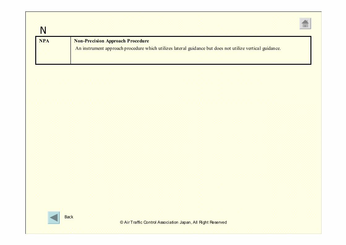
Non-Precision Approach Procedure
An instrument approach procedure which utilizes lateral guidance but does not utilize vertical guidance.
NPA
N
Back
© Air Traffic Control Association Japan, All Right Reserved
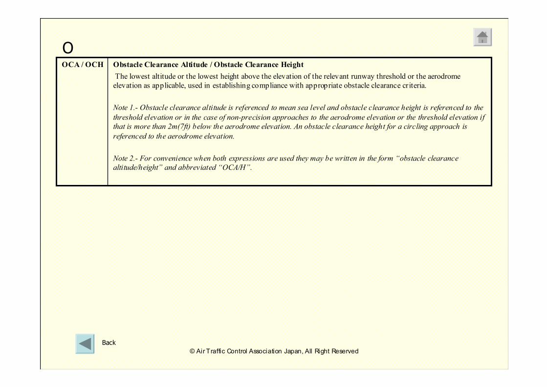
Obstacle Clearance Altitude / Obstacle Clearance Height
The lowest altitude or the lowest height above the elevation of the relevant runway threshold or the aerodrome
elevation as applicable, used in establishing compliance with appropriate obstacle clearance criteria.
Note 1.- Obstacle clearance altitude is referenced to mean sea level and obstacle clearance height is referenced to the
threshold elevation or in the case of non-precision approaches to the aerodrome elevation or the threshold elevation if
that is more than 2m(7ft) below the aerodrome elevation. An obstacle clearance height for a circling approach is
referenced to the aerodrome elevation.
Note 2.- For convenience when both expressions are used they may be written in the form “obstacle clearance
altitude/height” and abbreviated “OCA/H”.
OCA / OCH
O
Back
© Air Traffic Control Association Japan, All Right Reserved
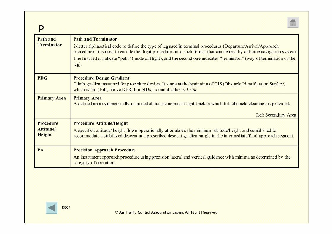
Procedure Design Gradient
Climb gradient assumed for procedure design. It starts at the beginning of OIS (Obstacle Identification Surface)
which is 5m (16ft) above DER. For SIDs, nominal value is 3.3%.
PDG
Path and Terminator
2-letter alphabetical code to define the type of leg used in terminal procedures (Departure/Arrival/Approach
procedure). It is used to encode the flight procedures into such format that can be read by airborne navigation system.
The first letter indicate “path” (mode of flight), and the second one indicates “terminator” (way of termination of the
leg).
Path and
Terminator
Precision Approach Procedure
An instrument approach procedure using precision lateral and vertical guidance with minima as determined by the
category of operation.
PA
Primary Area
A defined area symmetrically disposed about the nominal flight track in which full obstacle clearance is provided.
Ref: Secondary Area
Primary Area
Procedure Altitude/Height
A specified altitude/ height flown operationally at or above the minimum altitude/height and established to
accommodate a stabilized descent at a prescribed descent gradient/angle in the intermediate/final approach segment.
Procedure
Altitude/
Height
P
Back
© Air Traffic Control Association Japan, All Right Reserved
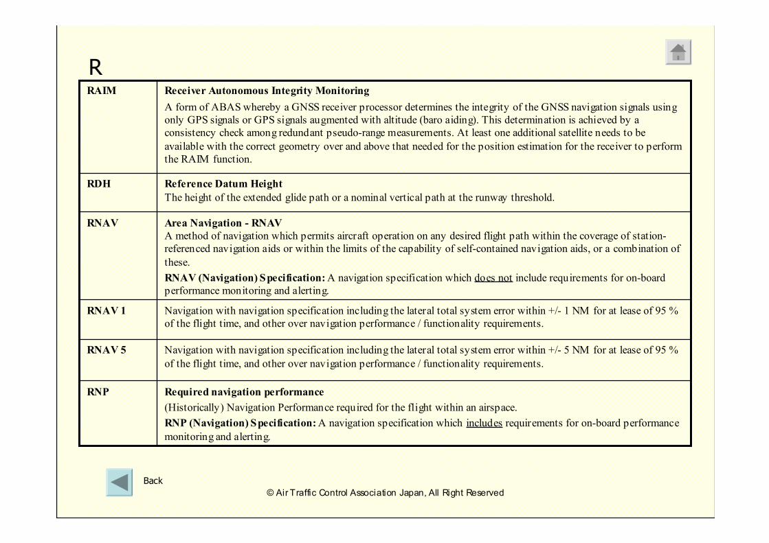
Navigation with navigation specification including the lateral total system error within +/- 5 NM for at lease of 95 %
of the flight time, and other over navigation performance / functionality requirements.
RNAV 5
Navigation with navigation specification including the lateral total system error within +/- 1 NM for at lease of 95 %
of the flight time, and other over navigation performance / functionality requirements.
RNAV 1
Reference Datum Height
The height of the extended glide path or a nominal vertical path at the runway threshold.
RDH
Receiver Autonomous Integrity Monitoring
A form of ABAS whereby a GNSS receiver processor determines the integrity of the GNSS navigation signals using
only GPS signals or GPS signals augmented with altitude (baro aiding). This determination is achieved by a
consistency check among redundant pseudo-range measurements. At least one additional satellite needs to be
available with the correct geometry over and above that needed for the position estimation for the receiver to perform
the RAIM function.
RAIM
Area Navigation - RNAV
A method of navigation which permits aircraft operation on any desired flight path within the coverage of station-
referenced navigation aids or within the limits of the capability of self-contained navigation aids, or a combination of
these.
RNAV (Navigation) Specification:A navigation specification which does not include requirements for on-board
performance monitoring and alerting.
RNAV
Required navigation performance
(Historically) Navigation Performance required for the flight within an airspace.
RNP (Navigation) Specification:A navigation specification which includes requirements for on-board performance
monitoring and alerting.
RNP
R
Back
© Air Traffic Control Association Japan, All Right Reserved
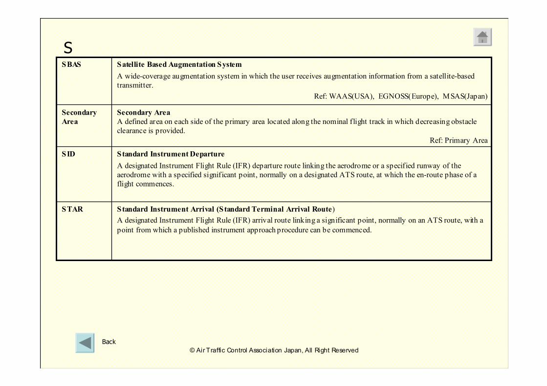
Satellite Based Augmentation System
A wide-coverage augmentation system in which the user receives augmentation information from a satellite-based
transmitter.
Ref: WAAS(USA), EGNOSS(Europe), MSAS(Japan)
SBAS
Standard Instrument Departure
A designated Instrument Flight Rule (IFR) departure route linking the aerodrome or a specified runway of the
aerodrome with a specified significant point, normally on a designated ATS route, at which the en-route phase of a
flight commences.
SID
Standard Instrument Arrival (Standard Terminal Arrival Route)
A designated Instrument Flight Rule (IFR) arrival route linking a significant point, normally on an ATS route, with a
point from which a published instrument approach procedure can be commenced.
STAR
Secondary Area
A defined area on each side of the primary area located along the nominal flight track in which decreasing obstacle
clearance is provided.
Ref: Primary Area
Secondary
Area
S
Back
© Air Traffic Control Association Japan, All Right Reserved
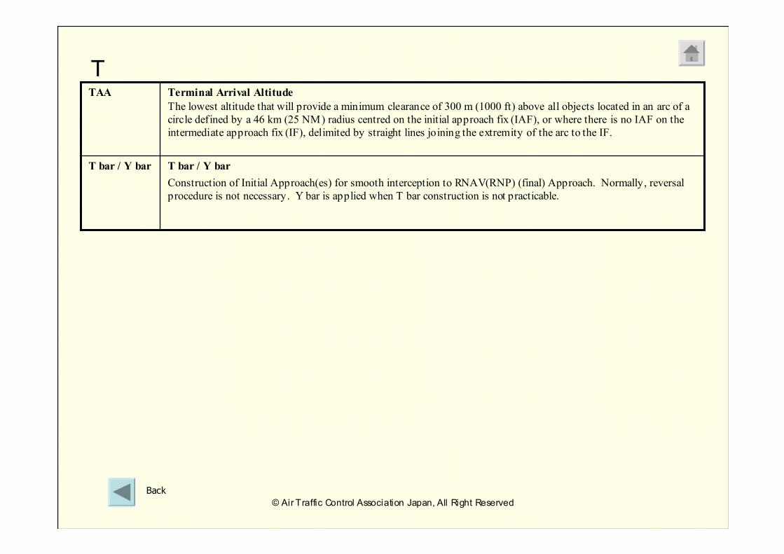
T bar / Y bar
Construction of Initial Approach(es) for smooth interception to RNAV(RNP) (final) Approach. Normally, reversal
procedure is not necessary. Y bar is applied when T bar construction is not practicable.
T bar / Y bar
Terminal Arrival Altitude
The lowest altitude that will provide a minimum clearance of 300 m (1000 ft) above all objects located in an arc of a
circle defined by a 46 km (25 NM) radius centred on the initial approach fix (IAF), or where there is no IAF on the
intermediate approach fix (IF), delimited by straight lines joining the extremity of the arc to the IF.
TAA
T
Back
© Air Traffic Control Association Japan, All Right Reserved
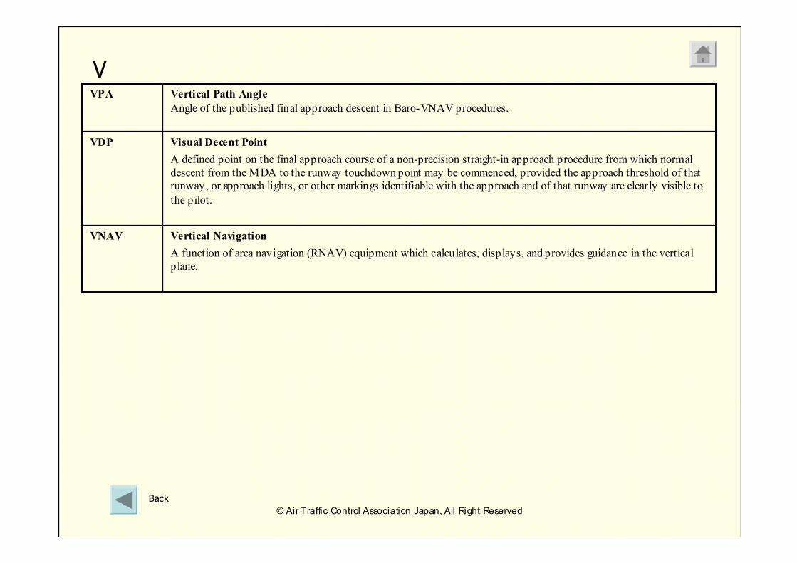
Visual Decent Point
A defined point on the final approach course of a non-precision straight-in approach procedure from which normal
descent from the MDA to the runway touchdown point may be commenced, provided the approach threshold of that
runway, or approach lights, or other markings identifiable with the approach and of that runway are clearly visible to
the pilot.
VDP
Vertical Navigation
A function of area navigation (RNAV) equipment which calculates, displays, and provides guidance in the vertical
plane.
VNAV
Vertical Path Angle
Angle of the published final approach descent in Baro-VNAV procedures.
VPA
V
Back
© Air Traffic Control Association Japan, All Right Reserved
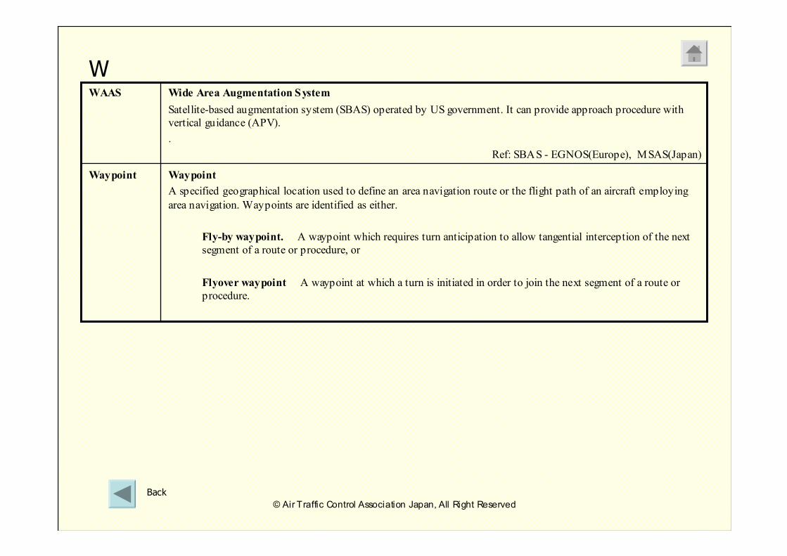
Waypoint
A specified geographical location used to define an area navigation route or the flight path of an aircraft employing
area navigation. Waypoints are identified as either.
Fly-by waypoint. A waypoint which requires turn anticipation to allow tangential interception of the next
segment of a route or procedure, or
Flyover waypoint A waypoint at which a turn is initiated in order to join the next segment of a route or
procedure.
Waypoint
Wide Area Augmentation System
Satellite-based augmentation system (SBAS) operated by US government. It can provide approach procedure with
vertical guidance (APV).
.
Ref: SBAS - EGNOS(Europe), MSAS(Japan)
WAAS
W
Back
© Air Traffic Control Association Japan, All Right Reserved
RNAV Training for ATCRNAV Training for ATC
© Air Traffic Control Association Japan, All Right Reserved
20072007
Air Traffic Control Association Japan
ENDEND