Embed Size (px)
Citation preview
"" RMIS View/Print Document Cover Sheet""
This document was retrieved from the Documentation and Records Manaqement (DRM) ISEARCH System. It is intended for Information only and may not be the most recent or updated version. Contact a Document Sewice Center (see Hanford Info for locations) if you need add it i o n al retrieval i n fo r m at i o n .
Accession #: Dl95064275
Document #: SD-WM-SFR-010
TitlelDesc: SOFWARE REQUIREMENTS SPECIFICATION FOR LOW MOISTURE MONITOR
Pages: 15
Page 1 Of
L
D i s t r i b u t i o n
5 . P r o j ./Prog./Dept./Div. :
75250
Character i za t ion Equipment NA Development 6. cog. Enor.:
GF Vargo tdi4H4F NA 7. Purchase Order Yo.:
5. Originator Remarks: For approval and r e l e a s e
.
9 . Equip./Cnponent No.:
IO. Syst~ lB ldg . lFac i l i ty : NA
[I Disapproved W c m n t s
A-6400-073 ( 0 8 / 9 4 ) yEF124
11. Receiver Renmrks:
ED-7400- 172- 1 10719 1 I
NA
NA 13. Permit/Penit Application Yo.:
NA
11/17/95
12. Major Asm. Dug. No.:
14. Required R e s p s e Date:
WHC-SD-WM-SFR-010, Rev. 0
SOFTWARE REQUIREMENTS SPECIFICATION FOR SURFACE MOISTURE MONITOR
M. GIHERA WHC ( H i L i n e ) , R ich land, WA 99352 U.S. Department o f Energy C o n t r a c t DE-AC06-87RL10930
Org Code: 75250 Charge Code: N4H4F B&R Code: EW3120074 T o t a l Pages: 13
Key Words: SOFTWARE, REQUIREMENTS, MOISTURE TANK FARMS, SURFACE
A b s t r a c t : Measurement System (SMMS) .
EDT/ECN: 602256 uc: 802
Prov ides t h e so f tware requ i remen ts f o r t h e Sur face M o i s t u r e
TRADEMARK DISCLAIMER. t rade name, trademark, manufacturer, or otherwise, does not necessar i ly cons t i t u te or imply i t s endorsement, reconmendation, or favor ing by the United States G o v e r m n t or any agency thereof or i t s contractors or subcontractors.
P r in ted in the Uni ted States of k r i c a . DocMent Control Services, P.O. Box 1970, Mai ls top H6-08. Richland UA 99352, Phone (50% 372-2420; Fax ( 5 0 9 ) 376-4989.
Reference here in t o any s p c i f i c conmercial product, process, or serv ice by
To ob ta in copies o f t h i s d O c m t , contact: UHClBCS
7 . - - , j L~-W,L,L pE!.EA,sE '&'\ 1 i .L I
i. E<\:' 1 v',;tj,s
Approved for Public Release
A-6400-073 (10/95) GEF321

WHC-SD-WM-SFR-010 Rev. 0
Page 1 of 12
SOFTWARE REQUIREMENTS SPECIFICATION FOR
SURFACE MOISTURE MONITOR
IMPACT LEVEL QS
Issued by Michael Gimera
(HiLine Engineering & Fabrication Inc.) November 1995
WHC-SD-Wh4-SFR-010 Rev.0 '
Page 4 of 12
SRS Software Requirements Specification
SDD Software Design Description
WHC Westinghouse Hanford Company
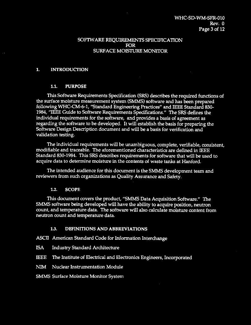
1.4. OVERVIEW
Section Two of this document discusses the general task of measuring moisture in waste tanks at Hanford. Section Three discusses the specific requirements of the software that are to be developed to satisfy the moisture measuring task
2. GENERAL DESCRIPTION
This section of the SRS describes the general factors that affect the product and its requirements. This section does not state specific requirements; it only makes those requirements easier to understand. Specific requirements are discussed in Section Three.
2.1. PRODUCT PERSPECTIVE
The SMMS data acquisition system is an independent system and not a sub part of any other system. For economy, the computer is to be shared with the LOW moisture measurement system. This sharing is practical because these two systems will never be operating simultaneously. Each deployment of the SMMS is to be temporary (less than 15 days in duration), however, repeated deployment is expected.
The SMMS will physically consist of two assemblies that are connected via electrical cable. The first assembly is a deployment system that is comprised of an arm that is lowered into a waste tank through a riser. At the lower end of the arm is a probe that returns neutron counts and temperature data. At the upper end of the arm is an enclosure that houses a winch to lower the probe from the arm to the waste surface. The arm can be rotated with a second winch enabling the probe to be placed as far as six feet from the riser centerline. The angle of rotation can be measured with an inclinometer installed in the arm. The deployment system can be swiveled radially to any compass point. The direction is determined from an electronic compass installed on the enclosure.
The second assembly is a data acquisition system located in a panel van. Among other instrumentation, the van houses an industrial computer and a NIh4 bin with a multichannel analyzer capable of reading four channels. The computer serves as an interface for the operator.
WHC-SD-WM-SFR-010 Rev. 0
Page 5 of 12
2.1.1. Computer
The computer provided for data acquisition and control is an industrial computer with the following features:
3 ISA bus slots.
0 3 PCI bus slots.
1 ISA/PCI slot.
Pentiumm' processor operates at 90 MHz.
40 MBytes of Random Access Memory.
One GByte Hard Disk Drive
3.5 inch 1.4 MByte floppy disk drive.
These features are not the minimum features required to operate the software, but are the features on the computer that is provided for this task.
Two serial ports and one parallel port,
A flat panel active matrix touch screen.
2.1.2. NIM Bin
The NIM bin is a backplane in a chassis. Together with modules it is used to provide instrumentation for nuclear applications. It houses three Preamplifiers (one for each detector) and a multichannel analyzer. The multichannel analyzer communicates with the computer through a ISA bus circuit card that contains dual-ported memory.
The preamplifiers increase the power of the return signals from the neutron probe and the multichannel analyzer processes these return signals.
2.1.3. Neutron Probe
The neutron probe contains a Californium source that emits neutrons. Some of these neutrons travel into the waste and are deflected by the hydrogen atoms in water. With enough deflections a few neutrons will strike the detectors in the probe. These detectors count neutron strikes and return a signal to the modules in the NIM bin.
IPentium@ is a registered trademark of Intel.
WHC-SD-WM-SFR-010 Rev. 0
Page 7 of 12
2.3. USER CHARACTERISTICS
The users of this software will be engineers that will perform the data acquisition tasks. Although the user interface will be simple to operate, it is assumed that the operators will already have a familiarity with the use of computers.
2.4. ASSUMPTIONS AND DEPENDENCIES
The development of this software is based on the assumption that :
development can be performed on National Instrument‘s@ LabVIEWM1 development environment.
this software will depend on TMAD software as described in WHC-SD-WM- CSRS-028, “System Design Description for the Th4AD Code.”
3. SPECIFIC REQUIREMENTS
3.1. FUNCTIONAL REQUIREMENTS
3.1.1. Operator Interface
3.1.1.1. Inputs
Take Measurement
A graphic control will be located on the computer screen. Pressing this control will cause the software to acquire data from the multichannel analyzer for each of the three detectors. The detector X-Y graphs on the computer screen will be updated. Using the data, the software will calculate the moisture for each detector and display it on the computer screen. Finally data and calculation results will be written to a data file as described in Section 3.1.2.
3.1.1.2. Outputs
Probe Position
A plan view of the probe’s direction and radial position from the riser centerline shall be displayed on the computer screen. This display shall be constantly updated, except during the taking of measurement data.
ILabVIEWM is a registered trademark of National Instruments, Austin, Texas.
WHC-SD-WM-SFR-010 Rev. 0
Page 8 of 12
Detector Graphs
A X-Y graph shall be displayed on the computer screen to show the spectrum from each of the three detectors. This display may either be three sets of data on one graph or three separate graphs with one set of data each. If three sets of data are plotted on one graph each set of data shall be plotted in a separate distinct color. The graph information will be updated each time the Take Measurement control is pressed.
Moisture Readout
The results of the moisture concentration calculation shall be displayed on the front panel for each activation of the Take Measurement control. The percentages shall be displayed as three separate numbers. Each of the three numbers will be the weight percent moisture at a different depth.
Status Indicator
During a moisture measurement the status of the measurement will be displayed graphically on the computer screen. This status, or progress, will give the operator an indication of the time left until completion of the measurement.
3.1.2. Data File
The data file will consist of header information and measurement data. The header will contain the filename of the data file, the time and date of the measurement, the version of the software creating the file and the position of the neutron probe (compass direction, distance from riser centerline and depth.
The measurement data consists of an array (spectrum) of integers for each of the three detectors, probe temperatures and the three resulting moisture percentages.
The file will be a disk file in a tabdelimited ASCII format. It will be stored in a subdirectory that has the current date for a name. The directory at the root level will be labeled "DATA" and within that directory will be a directory labeled "SMMS." Finally the file name will be named by the program and not the user. The file name will be the current date with an extension that consists of a sequential three digit number. An example absolute file path for a measurement file run on January 1,1996 is given below:
C\DATA\SMMS\01-01-96\01-01-96.001
The ASCII feature allows the file to be read by any text editor. The tab-deliited format allows the file to be read by most spreadsheet programs, including the ones in use at Hanford. The format of each of these three data elements will be single precision floating point numbers.


WHC-SD-WM-SFR-010 Rev. 0 '
Page 10 of 12
32.4. Error Handling
Any error during software operation shall be trapped and logged to an error file. The file shall be located in directory named "ERROR" located in the root directory of the computer's hard disk drive. The file shall be named "SMMs.LoG" and shall be in ASCII format. Entries shall be appended to this file to keep a running log of any errors. Each entry shall contain the date and time of the error, the unique error number and a text description of the error.
Error messages will be displayed to operator by use of a dialog box. Depending on the severity of the error, the operator may have the choice to continue. If program continuation is not possible the program will terminate after the operator dismisses the dialog box.
3.3. DESIGN CONSTRAINTS
Software constraints due to hardware limitations and system configuration are described in section 2.4 above. Other constraints on the software are dictated by the requirements in this document.
Due to delays involving the updating of the computer screen under WindowsTM, screen updates will be limited to one update per second. The detector graph displays will be updated after measurement data acquisition is completed.
3.4. EXTERNAL INTERFACE REQUIREMENTS
3.4.1. User Interfaces
The user interface will be a graphical interface. For ease of use the screen will mimic an instrument with icons of buttons representing controls and digital readouts depicting current information.
The user can set binary controls with a touch of the screen. Keyboard input, although available, should not be required.
3.4.2. Hardware interfaces
Hardware interfaces shall be through National Instrument's" data acquisition circuit boards, serial ports and a dual ported memory board. The use of National Instrument's@ boards eliminates the need for writing drivers since these boards all work fluently with National Instrument's@ LabVIEWa software development system.
Each input or output will be routed through a signal conditioning module or isolation device. The one exception to this is the digital input from the encoders. The output from the serial-to-parallel converters does not need to be conditioned.