Embed Size (px)
Citation preview

EESS
TTAABB
LLIISSHH
EEDD
IINN11992266
RIFASAMENTOINDUSTRIALE BT,CONDENSATORI 4In, SISTEMI FISSI E AUTOMATICI,FILTRI ATTIVI
LOW VOLTAGE POWER FACTOR CORRECTION 4In CAPACITORSAND EQUIPMENTACTIVE FILTERS
HISTORY DRIVES THE FUTURE

Gamma Prodotti
Ducati Energia Group
Tecnologia dei condensatori
Tecnologia dei condensatori in PPMh
Definizioni
Informazioni Generali sul rifasamento
Scelta e Calcolo del Sistema di Rifasamento
346781114
Product Range
Ducati Energia Group
Capacitors technology
Capacitors technology PPMh/MKPh
Definitions
General information about power factor correction
Choice and sizing of a power factor correction system
CondensatoriCondensatori Monofase
Serie MONO
Serie FLOPPY CAP
Condensatori Trifase
Serie MODULO XD
Serie MODULO XD MINI
19192122232527
CapacitorsSingle-phase Capacitors
MONO Series
FLOPPY CAP Series
Three-phase Capacitors
MODULO XD Series
MODULO XD MINI Series
Apparecchiature di rifasamento fisseDUCATI F50
DUCATI F120
282931
Fixed power factor correction equipmentDUCATI F50
DUCATI F120
Apparecchiature di rifasamento automaticheDUCATI 18-M
DUCATI 200-M
DUCATI 400-M
DUCATI 1600-R
3335394549
Automatic power factor correction equipmentDUCATI 18-M
DUCATI 200-M
DUCATI 400-M
DUCATI 1600-R
Apparecchiature automatiche con sistemi di filtroDUCATI 170-ML
DUCATI 1000-RL
DUCATI 1000-RL/HP
DUCATI 1000-RL/S
5557606366
Automatic equipment with filter systemDUCATI 170-ML
DUCATI 1000-RL
DUCATI 1000-RL/HP
DUCATI 1000-RL/S
Filtri armonici attiviDUCATI ActiSine
6969
Active harmonic filtersDUCATI ActiSine
Cassetti DUCATI C160
DUCATI C160-MINI
DUCATI C200-B
DUCATI C50-L-MINI
DUCATI C100-L
DUCATI C100-LB
73757677787980
ChassisDUCATI C160
DUCATI C160-MINI
DUCATI C200-B
DUCATI C50-L-MINI
DUCATI C100-L
DUCATI C100-LB
Regolatori di Potenza Reattiva REGOReattanze di sbarramento
ContattoriSezionatori
Note di riferimento - Avvertenze
8184878993
REGO Reactive Power ControllersBlocking reactorsContactorsIsolating switchesReference notes - Warnings
INDICE CONTENTS

3
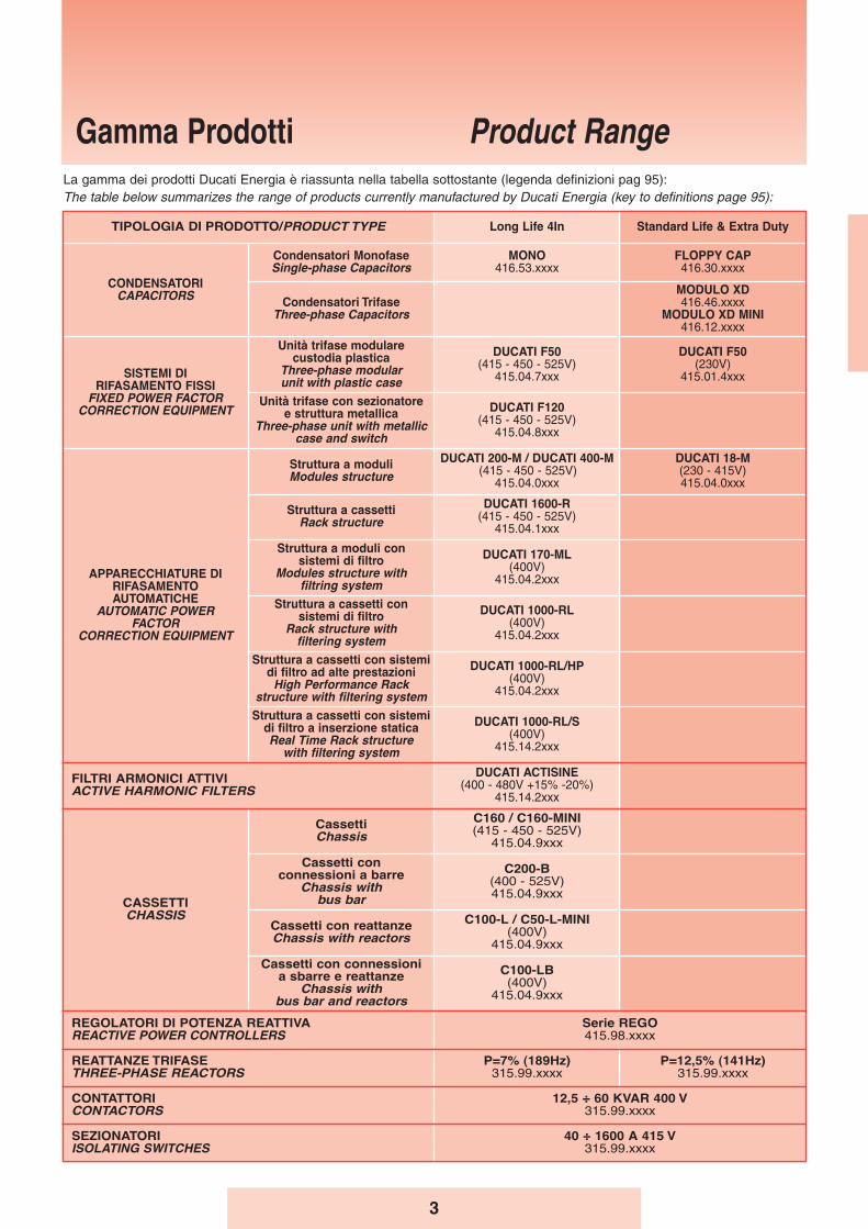
Gamma Prodotti Product RangeLa gamma dei prodotti Ducati Energia è riassunta nella tabella sottostante (legenda definizioni pag 95):The table below summarizes the range of products currently manufactured by Ducati Energia (key to definitions page 95):
TIPOLOGIA DI PRODOTTO/PRODUCT TYPE Long Life 4In Standard Life & Extra Duty
CONDENSATORICAPACITORS
Condensatori MonofaseSingle-phase Capacitors
MONO416.53.xxxx
FLOPPY CAP416.30.xxxx
Condensatori TrifaseThree-phase Capacitors
MODULO XD416.46.xxxx
MODULO XD MINI416.12.xxxx
SISTEMI DIRIFASAMENTO FISSI
FIXED POWER FACTORCORRECTION EQUIPMENT
Unità trifase modularecustodia plastica
Three-phase modularunit with plastic case
DUCATI F50(415 - 450 - 525V)
415.04.7xxx
DUCATI F50(230V)
415.01.4xxx
Unità trifase con sezionatoree struttura metallica
Three-phase unit with metalliccase and switch
DUCATI F120(415 - 450 - 525V)
415.04.8xxx
APPARECCHIATURE DI RIFASAMENTOAUTOMATICHE
AUTOMATIC POWERFACTOR
CORRECTION EQUIPMENT
Struttura a moduliModules structure
DUCATI 200-M / DUCATI 400-M(415 - 450 - 525V)
415.04.0xxx
DUCATI 18-M(230 - 415V)415.04.0xxx
Struttura a cassettiRack structure
DUCATI 1600-R(415 - 450 - 525V)
415.04.1xxx
Struttura a moduli consistemi di filtro
Modules structure withfiltring system
DUCATI 170-ML(400V)
415.04.2xxx
Struttura a cassetti consistemi di filtro
Rack structure with filtering system
DUCATI 1000-RL(400V)
415.04.2xxx
Struttura a cassetti con sistemidi filtro ad alte prestazioni
High Performance Rackstructure with filtering system
DUCATI 1000-RL/HP(400V)
415.04.2xxx
Struttura a cassetti con sistemidi filtro a inserzione staticaReal Time Rack structure
with filtering system
DUCATI 1000-RL/S(400V)
415.14.2xxx
FILTRI ARMONICI ATTIVIACTIVE HARMONIC FILTERS
DUCATI ACTISINE(400 - 480V +15% -20%)
415.14.2xxx
CASSETTI CHASSIS
Cassetti Chassis
C160 / C160-MINI(415 - 450 - 525V)
415.04.9xxx
Cassetti con connessioni a barre
Chassis withbus bar
C200-B(400 - 525V)415.04.9xxx
Cassetti con reattanzeChassis with reactors
C100-L / C50 -L-MINI(400V)
415.04.9xxx
Cassetti con connessioni a sbarre e reattanze
Chassis withbus bar and reactors
C100-LB(400V)
415.04.9xxx
REGOLATORI DI POTENZA REATTIVAREACTIVE POWER CONTROLLERS
Serie REGO415.98.xxxx
REATTANZE TRIFASETHREE-PHASE REACTORS
P=7% (189Hz)315.99.xxxx
P=12,5% (141Hz)315.99.xxxx
CONTATTORICONTACTORS
12,5 ÷ 60 KVAR 400 V315.99.xxxx
SEZIONATORIISOLATING SWITCHES
40 ÷ 1600 A 415 V315.99.xxxx
4
CAPACI TOR EXCELLENCE SINCE 1926CAPACI TOR EXCELLENCE SINCE 1926
DUCATI GROUP
In 1926 Ducati has been among the first to start industrialproduction of capacitors, and has been a market leader eversince.Since its foundation, Ducati Energia has always been in theforefront of technical and industrial development, leading theresearch shaping today’s technology and cooperating to theupgrades and improvements leading to the current IEC and ENStandards for Capacitors.Ducati Energia firstly introduced the Metallised PolypropyleneFilm technology and it’s innovative PPM and PPMh film set thereference for this technology, outclassing the obsolete paper/oiland gas technology in terms of superior performance andreduced dimensions.Constantly driven to quality, environmental engagement andsafety, Ducati Energia is fully certified following ISO 9001:2008,ISO 14001 and OHSAS 18001.
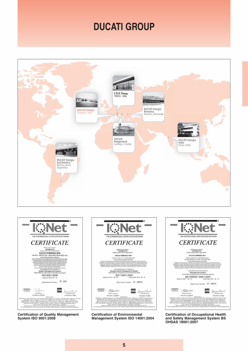
Today the Ducati Energia Group counts approx. 800 employeesworking in 6 plants:
• Ducati Energia (Bologna - Italy)• Ducati Energia Romania (Busteni - Romania)• Ducati Komponenti (Ludbreg - Croatia)• Ducati Energia India (Pune - India)• C.R.D. Centro Ricerche Ducati (Trento - Italy)• Ducati Energia Sud America (Buenos Aires - Argentina)
Ducati Energia Group main fields of activities are:
• Motor Lighting Capacitors• Power Electronics Capacitors• Power Factor Correction Capacitors and Systems (LV and MV)• Alternators and Ignition Systems• Wind Power Generators• Electrical Vehicles and Charging Stations for Electrical Vehicles • Energy Analysers• Control Systems for energy grids• Railways Signalling systems• Ticketing and Transport Automation systems
Quality
Utmost attention to product quality and customer service areconstants in DUCATI’s history and the main factors contributingto its success worldwide.Ducati has always been one of the first companies in its field, inItaly and in Europe, to adopt the most modern standards andprocedures in order to assure the highest level of product qualityand reliability.The QUALITY SYSTEM of Ducati Energia SpA, capacitordivision, as described in the Quality Manual, was one of the firstin Italy to be approved by the BSI in accordance with ISO 9002(EN 29002) procedures: Certificate of Registration N. FM22004.Ducati Energia is fully certified following ISO 9001:2008, ISO14001:2004 and OHSAS 18001:2007. All this has been achieved thanks to fully automated andintegrated production processes, completely new and innovativemachines, production process control methods based onaccurate specifications and the assigning of responsibility tooperators at all levels. Capacitors, systems and relays comply with the requirements setforth in EC Directives 73/23 and 93/68 (“Low Voltage Directive”),89/336 and 92/31 (“Electromagnetic Compatibility Directive”).The harmonized European standards of reference are EN60831-1 and EN 60831-2.Nearly all models are certified by international institutes and allare manufactured in full compliance with the requirements ofsaid standards. The failure rate (for capacitors only) is 300 per109 components x hours (reliability according to DIN 40040).
Già dal 1926 Ducati Energia si è differenziata per essere tra iprimi ad iniziare la produzione industriale di condensatori, econtinua ad essere un leader di mercato da allora.Sin dai primi anni della sua fondazione, Ducati Energia è semprestata in prima linea nello sviluppo tecnico e industriale,espandendo la propria area di ricerca nell’utilizzo delle nuovetecnologie, in costante sviluppo di aggiornamenti e miglioramentiche hanno portato alle attuali norme IEC e EN per condensatori.Ducati Energia ha in primo luogo introdotto la tecnologia a film dipolipropilene metallizzato ed i suoi innovativi film PPM e PPMhsono ad oggi il riferimento per questa tecnologia, surclassandola tecnologia della carta / petrolio e gas obsolete in termini disuperiorità di prestazioni e dimensioni ridotte.Particolarmente attenta alla qualità, all’ambiente e alla sicurezza,Ducati Energia ha ottenuto le certificazioni ISO 9001:2008, ISO 14001 e OHSAS 18001.
Oggi il Gruppo Energia Ducati conta circa 800 dipendenti chelavorano in sei stabilimenti:
• Ducati Energia (Bologna - Italia)• Ducati Energia Romania (Busteni - Romania)• Ducati Komponenti (Ludbreg - Croazia)• Ducati Energia India (Pune - India)• Ducati Energia Sud America (Buenos Aires - Argentina)• C.R.D. Centro Ricerche Ducati (Trento - Italia)
Principali settori di attività del Gruppo Ducati Energia sono:
• Condensatori e sistemi BT e MT per rifasamento industriale• Elettronica di Potenza• Condensatori per motori e condensatori per lampade• Analizzatori Energia• Veicoli elettrici e le colonnine di ricarica per veicoli elettrici• Alternatori e impianti di accensione• Generatori di Energia eolica• Sistemi di controllo per le reti energetiche• Sistemi di segnalazione ferroviaria• Sistemi di automazione di ticketing e trasporti
Qualità
L’attenzione massima alla qualità del prodotto e del servizio alcliente, è una costante nella storia della DUCATI ed è il fattoreprincipale che ne ha reso noto il nome in tutto il mondo.L’azienda è sempre stata fra le prime in Italia e, nel suo campo,in Europa ad adottare le normative e le procedure più moderneper garantire il livello massimo di qualità ed affidabilità deiprodotti.Il SISTEMA QUALITÀ della Ducati Energia spa, sezionecondensatori, descritti nel Manuale della Qualità è stato fra iprimi in Italia ad essere approvato dal BSI secondo le procedureISO 9002 (EN 29002): Certificato di Registrazione N. FM22004.È approvato dal CSQ secondo le norme ISO 9001:2008 -14001:2004 - OHSAS 18001:2007.Tutto ciò è stato ottenuto grazie a processi produttivi fortementeintegrati ed automatizzati, a macchine e tecnologiecompletamente nuove e innovative, a metodologie del controllodel processo produttivo basate su accurate specifiche e sullaresponsabilizzazione degli operatori a tutti i livelli.I condensatori, i sistemi e i regolatori sono conformi alle disposizionidelle Direttive Comunitarie 73/23 e 93/68 (“Direttive sulla BassaTensione”), 89/336 e 92/31 (“Compatibilità Elettromagnetica”).La Norma Armonizzata europea di riferimento è la EN 60831-1e la EN 60831-2.La quasi totalità dei modelli è certificata da istituti internazionali etutti sono costruiti con gli stessi criteri di assoluto rispetto dellenormative indicate. Il tasso di guasto è (solo per i condensatori) 300su 109 componenti x ore (affidabilità secondo le norme DIN 40040).
5
DUCATI GROUP
Certification of Quality ManagementSystem ISO 9001:2008
Certification of EnvironmentalManagement System ISO 14001:2004
Certification of Occupational Healthand Safety Management System BSOHSAS 18001:2007

INTRODUZIONE
Ducati nasce nel 1926 introducendo per prima in Italia, e frale prime al mondo, condensatori per le apparecchiature diradiotrasmissione prodotte da Guglielmo Marconi.Da questa tradizione, che ha sempre visto Ducatiall’avanguardia nella tecnologia di elementi capacitivi, si ègiunti all’utilizzo innovativo del film PPM e PPMh e allanascita del condensatore 4In.Le prestazioni superiori e le dimensioni ridotte rispetto alleormai obsolete soluzioni in carta e olio e in gas, rendono icondensatori prodotti in PPM/PPMh il nuovo standard diriferimento per il rifasamento industriale.
Tutti i condensatori prodotti da Ducati Energia sono dotati diun dispositivo di protezione conforme alle norme EN 60831-1/2. Questa protezione è stata ottenuta attraverso unaparticolare tecnologia costruttiva, che in caso di guastodisconnette i collegamenti per sovra-pressione, lasciandointegro l’isolamento verso la custodia e impedendo che ilcondensatore possa scoppiare o bruciare.Il dispositivo è stato studiato e dimensionato al fine direndere più efficace e tempestivo l’intervento sia con bassesia ad alte correnti di cortocircuito (fino a 10.000 A).
TECNOLOGIA PPMh/MKPh 4In
La continua ricerca nei laboratori Ducati Energia ha portatoallo sviluppo di un film in polipropilene con una specialemetallizzazione, al fine di favorire il processo diautorigenerazione e diminuire le perdite dielettriche. L’innovativa metallizzazione permette al polipropilene unostress minore durante il funzionamento, quindi mantiene lecaratteristiche dielettriche per un tempo notevolmente piùlungo e allo stesso tempo consente prestazioni notevolmentesuperiori sia in termini di corrente 4In che di tensione.
GAMMA LONG LIFE 4InQuesta innovativa gamma di condensatori per il rifasamentoindustriale con elementi avvolti con film PPMh, si impone peraffidabilità, prestazioni e compattezza.La più efficace autorigenerazione e le ridotte perditedielettriche permettono di ottenere durata e prestazioni intensione e corrente paragonabili ai condensatori in carta eolio con ingombri ridotti.Fanno parte di questa tipologia i condensatori appartenentialle famiglie:
➣ condensatori monofase serie MONO 416.53
INTRODUCTION
Ducati was founded in 1926 and was the first company inItaly, and among the first in the world, to introduce capacitorsfor the radiobroadcasting equipment produced by GuglielmoMarconi.Building upon this tradition, which has always seen Ducati inthe forefront of capacitor technology, the company hasdeveloped the innovative PPM and PPMh film with 4Incapacitor.Superior performance and reduced dimensions compared tothe by now obsolete paper and oil and gas solutions makePPM/PPMh capacitors the new standard of reference forindustrial power factor correction systems.
All the capacitors manufactured by Ducati Energia feature aprotection device conforming to standards EN 60831-1/2. Thisprotection has been achieved by means of a specialengineering technology: if a fault occurs the connections will bebroken due to overpressure, leaving the insulation of the caseintact and preventing the capacitor from exploding or burning.The device has been designed and dimensioned to ensuremore efficient, prompt operation with both low and high shortcircuit currents (up to 10,000 A).
TECHNOLOGY PPMh/MKPh 4In
The continuous research conducted in Ducati Energialaboratories has led to the development of a polypropylenefilm with a special metallization, whose purpose is to favourthe self-healing process and reduce dielectric losses. Thanks to this innovative metallization treatment, thepolypropylene is subjected to less stress during operation.Therefore it maintains its dielectric properties for asignificantly longer time while delivering significantly betterperformance in terms of both 4In current and voltage.
LONG LIFE SERIES 4InThis innovative range of industrial power factor correctioncapacitors featuring elements wound with PPMh film setsnew standards of reliability, performance and compactness.More effective self-healing and reduced dielectric lossesmake it possible to obtain a lifespan and performances interms of voltage and current that are comparable to those ofpaper and oil capacitors while reducing size.Capacitors of this type belong to the families:
➣ Series MONO 416.53 single-phase capacitors
Tecnologia dei condensatori
CapacitorsTechnology
6
7
TECNOLOGIA PPM / MKP
La tecnologia del polipropilene metallizzato (PPM / MKP),consiste nel depositare per evaporazione sotto vuoto unsottilissimo strato di metallo su un lato del film dipolipropilene.Gli elementi capacitivi costruiti con questa tecnologia vengonoottenuti avvolgendo due film di polipropilene. Le armature delcondensatore sono costituite dalla metallizzazione dei due filme il dielettrico dal film di polipropilene stesso.Pregio principale dei condensatori con armatura metallizzataè di essere autorigenerabili, di essere capaci cioè, diripristinare le proprietà elettriche al verificarsi di un cortocircuito fra le armature.In conseguenza del ridotto spessore dell’armatura, lacorrente di corto circuito nella zona circostante il guasto, è ingrado di vaporizzare la metallizzazione, estinguendoautomaticamente il corto circuito, senza un’apprezzabileriduzione di capacità o dispendio d'energia.
GAMMA EXTRA DUTY (XD) E STANDARD LIFE (SL)In questi condensatori l’agente impregnante è rappresentatoda un particolare tipo di resina. Ducati Energia ha messo apunto una composizione di resina ecocompatibile ad altastabilità dielettrica, che consente di rimuovere totalmenteogni possibile rischio di presenza di molecole d’aria e acquaall’interno del condensatore. Fanno parte di questa tipologiai condensatori appartenenti alle famiglie:
➣ condensatori trifase serie MODULO XD 416.46 (XD)
➣ condensatori trifase serie MODULO XD Mini 416.12 (XD)
➣ condensatori monofase serie FLOPPY CAP 416.30 (SL)
PPM / MKP TECHNOLOGY
Metallized polypropylene technology (PPM / MKP) utilizes avacuum evaporation technique to deposit an extremely thinlayer of metal on one side of the polypropylene film.The capacitor elements built using this technology areobtained by winding two polypropylene films. The capacitorplates consist in the metallized surface of the two films andthe dielectric is the propylene film itself.The main advantage of capacitors with metallized plates istheir self-healing capacity. This means that they are capableof restoring their electrical properties following theoccurrence of a short circuit between the plates.Due to the reduced thickness of the plates, the short circuitcurrent generated in the area of a fault is capable ofvaporizing the metal coating; the short circuit is therebyautomatically extinguished without an appreciable reductionin capacitance or expenditure of energy.
EXTRA DUTY (XD) AND STANDARD LIFE (SL) SERIESIn these capacitors the impregnating agent is a special typeof resin. Ducati Energia has developed an ecofriendly resincomposition displaying high dielectric stability, whichcompletely eliminates every possible risk of air and watermolecules being present inside the capacitor. This categoryincludes the capacitors belonging to the families:
➣ Series MODULO XD 416.46 three-phase capacitors (XD)
➣ Series MODULO XD Mini 416.12 three-phase capacitors (XD)
➣ Series FLOPPY CAP 416.30 single-phase capacitors (SL)
Tecnologia dei condensatori in PPMh
CapacitorTechnology PPMh/MKPh
Rated voltage (Un)This is the maximum effective value of the alternating sinusoidalvoltage for which the capacitor was designed.
Rated power (Qn)This is the reactive power delivered by the capacitor at the ratedvoltage and frequency applied.
Rated capacitance (Cn)This is the value which permits delivery of the rated powerapplying the rated voltage and frequency to the terminals.
Rated current (In)This is the effective value of the alternating current thatcirculates through the capacitor when the rated voltage andfrequency are applied at the rated capacitance.
OPERATING CONDITIONSUnlike most electrical equipment, power factor correctioncapacitors, each time they are energized, continuously operateat full load or at loads which differ from this value only as aconsequence of variations in voltage and frequency.Overstressing and overheating shorten the lifespan of thecapacitor. For this reason the operating conditions (temperature,voltage and current) must be carefully controlled in order toobtain optimum results as regards the lifespan of the capacitor.
VoltageThe capacitors are produced in accordance with standards EN60831-1/2, which regulate their manufacture, testing, installationand application of capacitors, indicating the following maximumovervoltages:+10% for 8 hours every 24 hours+15% for 30 minutes every 24 hours+20% for 5 minutes +30% for 1 minute.
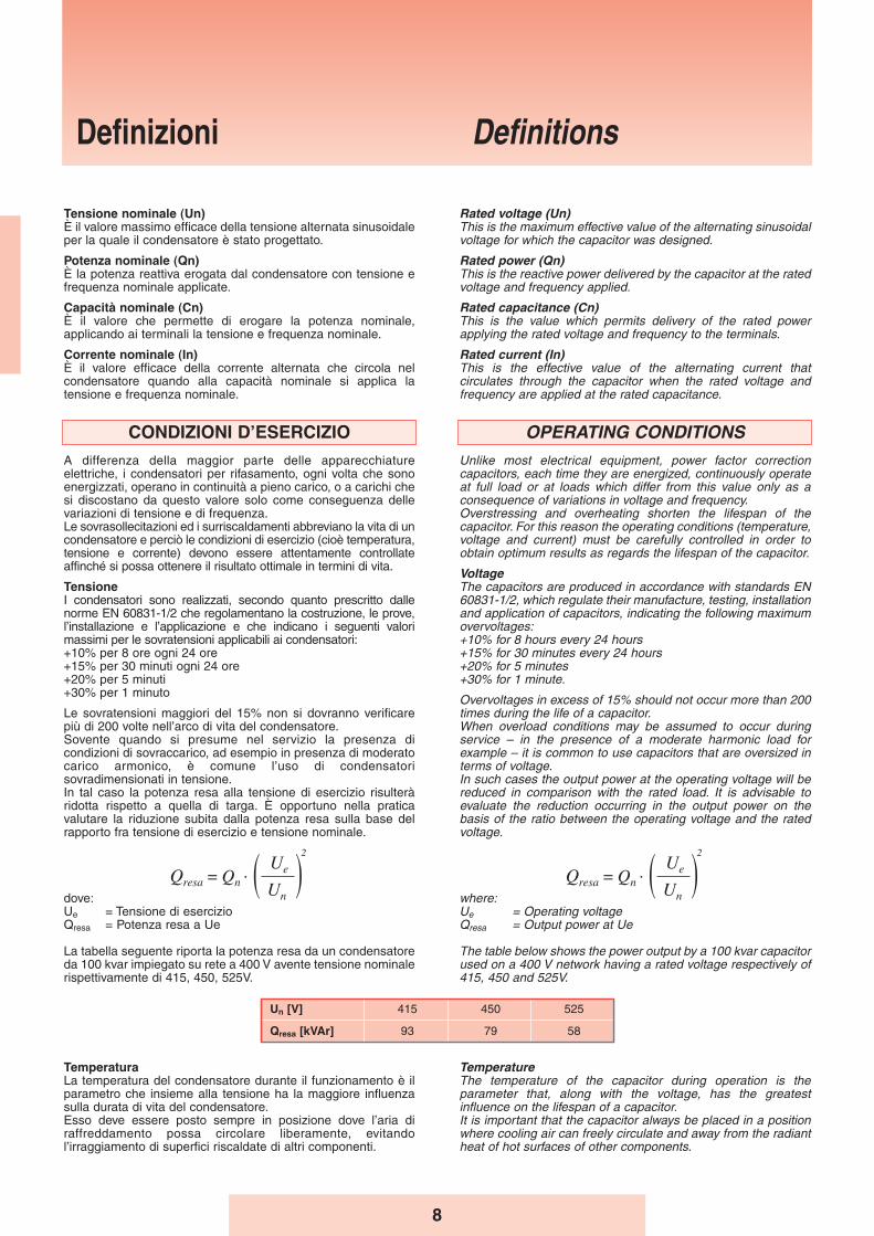
Overvoltages in excess of 15% should not occur more than 200times during the life of a capacitor.When overload conditions may be assumed to occur duringservice – in the presence of a moderate harmonic load forexample – it is common to use capacitors that are oversized interms of voltage.In such cases the output power at the operating voltage will bereduced in comparison with the rated load. It is advisable toevaluate the reduction occurring in the output power on thebasis of the ratio between the operating voltage and the ratedvoltage.
where:Ue = Operating voltageQresa = Output power at Ue
The table below shows the power output by a 100 kvar capacitorused on a 400 V network having a rated voltage respectively of415, 450 and 525V.
Definizioni Definitions
8
Tensione nominale (Un)È il valore massimo efficace della tensione alternata sinusoidaleper la quale il condensatore è stato progettato.
Potenza nominale (Qn)È la potenza reattiva erogata dal condensatore con tensione efrequenza nominale applicate.
Capacità nominale (Cn)È il valore che permette di erogare la potenza nominale,applicando ai terminali la tensione e frequenza nominale.
Corrente nominale (In)È il valore efficace della corrente alternata che circola nelcondensatore quando alla capacità nominale si applica latensione e frequenza nominale.
CONDIZIONI DʼESERCIZIO
A differenza della maggior parte delle apparecchiatureelettriche, i condensatori per rifasamento, ogni volta che sonoenergizzati, operano in continuità a pieno carico, o a carichi chesi discostano da questo valore solo come conseguenza dellevariazioni di tensione e di frequenza.Le sovrasollecitazioni ed i surriscaldamenti abbreviano la vita di uncondensatore e perciò le condizioni di esercizio (cioè temperatura,tensione e corrente) devono essere attentamente controllateaffinché si possa ottenere il risultato ottimale in termini di vita.
TensioneI condensatori sono realizzati, secondo quanto prescritto dallenorme EN 60831-1/2 che regolamentano la costruzione, le prove,l’installazione e l’applicazione e che indicano i seguenti valorimassimi per le sovratensioni applicabili ai condensatori:+10% per 8 ore ogni 24 ore+15% per 30 minuti ogni 24 ore+20% per 5 minuti+30% per 1 minuto
Le sovratensioni maggiori del 15% non si dovranno verificarepiù di 200 volte nell’arco di vita del condensatore.Sovente quando si presume nel servizio la presenza dicondizioni di sovraccarico, ad esempio in presenza di moderatocarico armonico, è comune l’uso di condensatorisovradimensionati in tensione.In tal caso la potenza resa alla tensione di esercizio risulteràridotta rispetto a quella di targa. È opportuno nella praticavalutare la riduzione subita dalla potenza resa sulla base delrapporto fra tensione di esercizio e tensione nominale.
dove:Ue = Tensione di esercizioQresa = Potenza resa a Ue
La tabella seguente riporta la potenza resa da un condensatoreda 100 kvar impiegato su rete a 400 V avente tensione nominalerispettivamente di 415, 450, 525V.
Un [V] 415 450 525
Qresa [kVAr] 93 79 58
TemperaturaLa temperatura del condensatore durante il funzionamento è ilparametro che insieme alla tensione ha la maggiore influenzasulla durata di vita del condensatore.Esso deve essere posto sempre in posizione dove l’aria diraffreddamento possa circolare liberamente, evitandol’irraggiamento di superfici riscaldate di altri componenti.
TemperatureThe temperature of the capacitor during operation is theparameter that, along with the voltage, has the greatestinfluence on the lifespan of a capacitor. It is important that the capacitor always be placed in a positionwhere cooling air can freely circulate and away from the radiantheat of hot surfaces of other components.
9
Temperatura dellʼaria ambiente / Category Ambient air temperatureCategoria / Category
MaxValore medio più alto in un periodo di: / Highest mean over any period of:
24 H 1 ANNO / 1 YEAR-25/A -25 + 40 °C 40 30 20
-25/B -25 + 45 °C 45 35 25
-25/C -25 + 50 °C 50 40 30
-25/D -25 + 55 °C 55 45 35
Quando i condensatori siano posti in armadi chiusi, si devonoprevedere fessure di ventilazione che consentano un facilescambio di aria tra interno ed esterno dell’armadio. Quandoviceversa il grado di protezione dell’armadio non consentaquesto scambio, gli spazi interni devono essere molto più ampie la collocazione dei condensatori deve essere studiataattentamente affinché opportuni canali consentano lacircolazione dell’aria di raffreddamento che deve essere forzatacon opportuni ventilatori. In linea generale la temperaturadell’aria di raffreddamento all’interno dell’armadio non devedifferire di più di 5°C rispetto all’aria esterna al quadro.
Temperatura dellʼaria di raffreddamentoÈ la temperatura dell’aria di raffreddamento misurata nel puntopiù caldo del banco di condensatori, alle condizioni di regime, ametà fra due condensatori o sulla superficie di uno di essi.
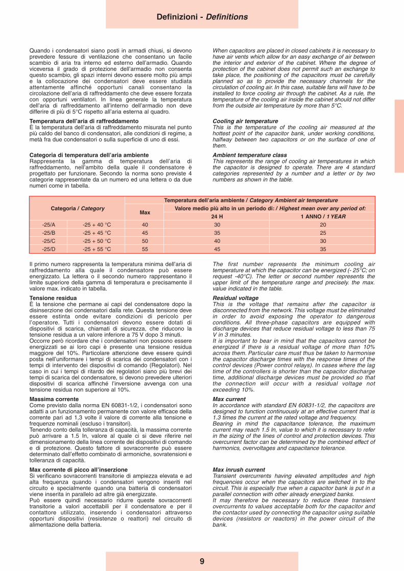
Categoria di temperatura dellʼaria ambienteRappresenta la gamma di temperatura dell’aria diraffreddamento, nell’ambito della quale il condensatore èprogettato per funzionare. Secondo la norma sono previste 4categorie rappresentate da un numero ed una lettera o da duenumeri come in tabella.
Il primo numero rappresenta la temperatura minima dell’aria diraffreddamento alla quale il condensatore può essereenergizzato. La lettera o il secondo numero rappresentano illimite superiore della gamma di temperatura e precisamente ilvalore max. indicato in tabella.
Tensione residuaÈ la tensione che permane ai capi del condensatore dopo ladisinserzione dei condensatori dalla rete. Questa tensione deveessere estinta onde evitare condizioni di pericolo perl’operatore. Tutti i condensatori devono essere dotati didispositivi di scarica, chiamati di sicurezza, che riducono latensione residua a un valore inferiore a 75 V dopo 3 minuti.Occorre però ricordare che i condensatori non possono essereenergizzati se ai loro capi è presente una tensione residuamaggiore del 10%. Particolare attenzione deve essere quindiposta nell’uniformare i tempi di scarica dei condensatori con itempi di intervento dei dispositivi di comando (Regolatori). Nelcaso in cui i tempi di ritardo dei regolatori siano più brevi deitempi di scarica del condensatore, si devono prevedere ulterioridispositivi di scarica affinché l’inversione avvenga con unatensione residua non superiore al 10%.
Massima correnteCome previsto dalla norma EN 60831-1/2, i condensatori sonoadatti a un funzionamento permanente con valore efficace dellacorrente pari ad 1,3 volte il valore di corrente alla tensione efrequenze nominali (escluso i transitori).Tenendo conto della tolleranza di capacità, la massima correntepuò arrivare a 1.5 In, valore al quale ci si deve riferire neldimensionamento della linea corrente dei dispositivi di comandoe di protezione. Questo fattore di sovracorrente può esseredeterminato dall’effetto combinato di armoniche, sovratensioni etolleranza di capacità.
Max corrente di picco allʼinserzioneSi verificano sovracorrenti transitorie di ampiezza elevata e adalta frequenza quando i condensatori vengono inseriti nelcircuito e specialmente quando una batteria di condensatoriviene inserita in parallelo ad altre già energizzate.Può essere quindi necessario ridurre queste sovracorrentitransitorie a valori accettabili per il condensatore e per ilcontattore utilizzato, inserendo i condensatori attraversoopportuni dispositivi (resistenze o reattori) nel circuito dialimentazione della batteria.
When capacitors are placed in closed cabinets it is necessary tohave air vents which allow for an easy exchange of air betweenthe interior and exterior of the cabinet. Where the degree ofprotection of the cabinet does not permit such an exchange totake place, the positioning of the capacitors must be carefullyplanned so as to provide the necessary channels for thecirculation of cooling air. In this case, suitable fans will have to beinstalled to force cooling air through the cabinet. As a rule, thetemperature of the cooling air inside the cabinet should not differfrom the outside air temperature by more than 5°C.
Cooling air temperatureThis is the temperature of the cooling air measured at thehottest point of the capacitor bank, under working conditions,halfway between two capacitors or on the surface of one ofthem.
Ambient temperature classThis represents the range of cooling air temperatures in whichthe capacitor is designed to operate. There are 4 standardcategories represented by a number and a letter or by twonumbers as shown in the table.
The first number represents the minimum cooling airtemperature at which the capacitor can be energized (- 25°C; onrequest -40°C). The letter or second number represents theupper limit of the temperature range and precisely. the max.value indicated in the table.
Residual voltageThis is the voltage that remains after the capacitor isdisconnected from the network. This voltage must be eliminatedin order to avoid exposing the operator to dangerousconditions. All three-phase capacitors are equipped withdischarge devices that reduce residual voltage to less than 75V in 3 minutes.It is important to bear in mind that the capacitors cannot beenergized if there is a residual voltage of more than 10%across them. Particular care must thus be taken to harmonisethe capacitor discharge times with the response times of thecontrol devices (Power control relays). In cases where the lagtime of the controllers is shorter than the capacitor dischargetime, additional discharge devices must be provided so thatthe connection will occur with a residual voltage notexceeding 10%.
Max currentIn accordance with standard EN 60831-1/2, the capacitors aredesigned to function continuously at an effective current that is1.3 times the current at the rated voltage and frequency.Bearing in mind the capacitance tolerance, the maximumcurrent may reach 1.5 ln, value to which it is necessary to referin the sizing of the lines of control and protection devices. Thisovercurrent factor can be determined by the combined effect ofharmonics, overvoltages and capacitance tolerance.
Max inrush current Transient overcurrents having elevated amplitudes and highfrequencies occur when the capacitors are switched in to thecircuit. This is especially true when a capacitor bank is put in aparallel connection with other already energized banks.It may therefore be necessary to reduce these transientovercurrents to values acceptable both for the capacitor andthe contactor used by connecting the capacitor using suitabledevices (resistors or reactors) in the power circuit of thebank.
Definizioni - Definitions
Il valore di picco delle sovracorrenti causate da operazioni dimanovra deve essere limitato al valore massimo di 200 In(valore di cresta del 1° ciclo).
Protezione e sicurezzaPer una sicura protezione, gli elementi capacitivi checostituiscono le unità sono individualmente corredati deldispositivo di sicurezza a sovrappressione.La sua funzione è di interrompere il corto circuito quando, allafine della sua vita il condensatore non riesce più adautorigenerarsi. Il dispositivo sfrutta la pressione che si sviluppainternamente con il deterioramento del film per effetto delsurriscaldamento dovuto al corto circuito, per interrompere icollegamenti del terminale.Da notare che un fusibile esterno non è altrettanto affidabile inquanto la corrente di corto circuito essendo fortemente limitatadalla metallizzazione, è largamente variabile.Tutti condensatori sono costruiti con materiali compatibili conl’ambiente, conformi alle norme EN 60831-1/2.
10
The crest value of overcurrents caused during switchingoperations must be limited to a maximum of 100 ln (crest valueof the 1st cycle).
Protection and safetyTo ensure protection, the capacitor elements making up the unitare individually fitted with an overpressure safety device.The function of this device is to interrupt a short circuit when thecapacitor reaches the end of its useful life and is no longer ableto regenerate itself. This device breaks the connections of theterminal by exploiting the internal pressure that builds during thefilm’s decomposition, which results from the overheating causedby the short circuit.It should be noted that an external fuse is not as reliable sincethe short circuit current, being strongly limited by the metallizedsurface, may vary widely.All the capacitors are built with environmentally friendlymaterials conforming to standards EN 60831-1/2.
Definizioni - Definitions
11
PERCHÉ INSTALLARE UN SISTEMADI RIFASAMENTO
Molti sono gli obiettivi da porsi durante il progetto di un impiantoelettrico: oltre la sicurezza e l’affidabilità di funzionamento èmolto importante il corretto utilizzo dell’energia elettrica. Ognicircuito, ogni apparecchiatura, deve essere concepita per dare ilmassimo rendimento globale nella trasformazione dalla fonte dienergia al lavoro utilizzato.Fra le azioni che consentono di ottimizzare l’utilizzo dell’energiaelettrica, si annovera fra le più importanti il rifasamento degliimpianti elettrici.Quantificando questo aspetto dal punto di vista dell’Entefornitore dell’energia elettrica, portare il fattore di potenza mediodi funzionamento della rete da 0.7 a 0.95 significa:
➣ ridurre i costi di circa il 45% per le perdite ohmiche nella rete;➣ aumentare del 35% la potenzialità degli impianti di
produzione e distribuzione.
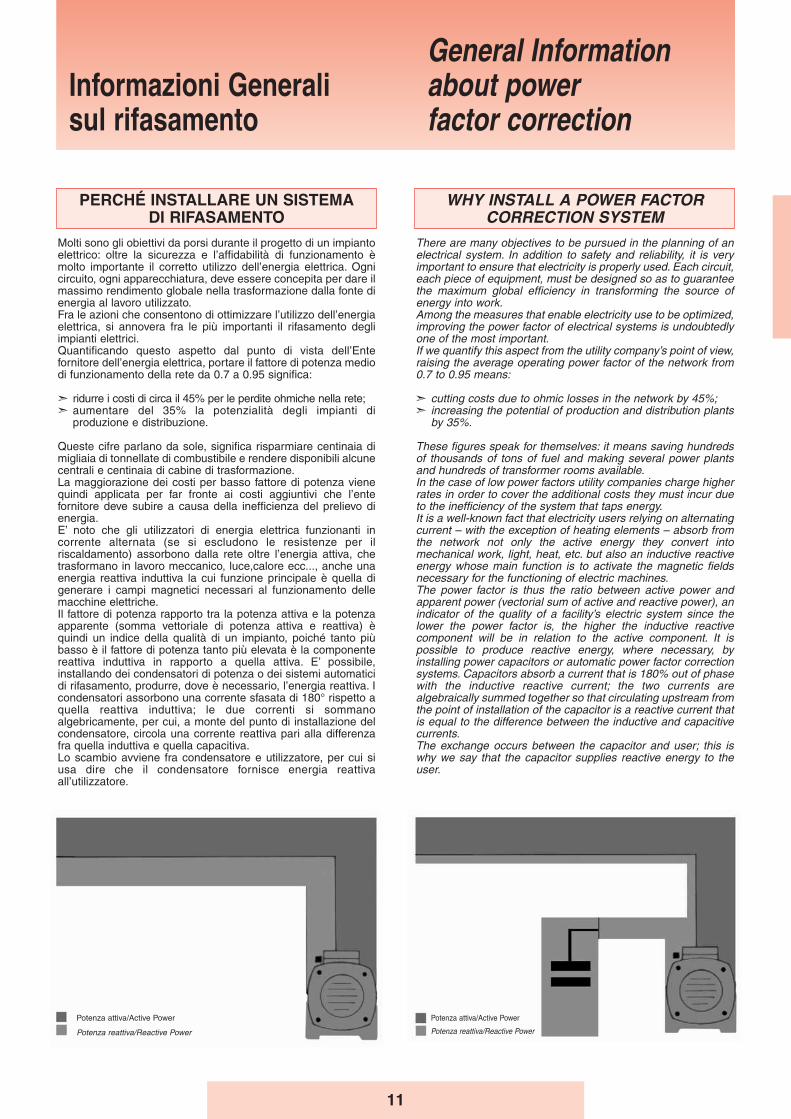
Queste cifre parlano da sole, significa risparmiare centinaia dimigliaia di tonnellate di combustibile e rendere disponibili alcunecentrali e centinaia di cabine di trasformazione.La maggiorazione dei costi per basso fattore di potenza vienequindi applicata per far fronte ai costi aggiuntivi che l’entefornitore deve subire a causa della inefficienza del prelievo dienergia.E’ noto che gli utilizzatori di energia elettrica funzionanti incorrente alternata (se si escludono le resistenze per ilriscaldamento) assorbono dalla rete oltre l’energia attiva, chetrasformano in lavoro meccanico, luce,calore ecc..., anche unaenergia reattiva induttiva la cui funzione principale è quella digenerare i campi magnetici necessari al funzionamento dellemacchine elettriche.Il fattore di potenza rapporto tra la potenza attiva e la potenzaapparente (somma vettoriale di potenza attiva e reattiva) èquindi un indice della qualità di un impianto, poiché tanto piùbasso è il fattore di potenza tanto più elevata è la componentereattiva induttiva in rapporto a quella attiva. E’ possibile,installando dei condensatori di potenza o dei sistemi automaticidi rifasamento, produrre, dove è necessario, l’energia reattiva. Icondensatori assorbono una corrente sfasata di 180° rispetto aquella reattiva induttiva; le due correnti si sommanoalgebricamente, per cui, a monte del punto di installazione delcondensatore, circola una corrente reattiva pari alla differenzafra quella induttiva e quella capacitiva.Lo scambio avviene fra condensatore e utilizzatore, per cui siusa dire che il condensatore fornisce energia reattivaall’utilizzatore.
WHY INSTALL A POWER FACTORCORRECTION SYSTEM
There are many objectives to be pursued in the planning of anelectrical system. In addition to safety and reliability, it is veryimportant to ensure that electricity is properly used. Each circuit,each piece of equipment, must be designed so as to guaranteethe maximum global efficiency in transforming the source ofenergy into work.Among the measures that enable electricity use to be optimized,improving the power factor of electrical systems is undoubtedlyone of the most important.If we quantify this aspect from the utility company’s point of view,raising the average operating power factor of the network from0.7 to 0.95 means:
➣ cutting costs due to ohmic losses in the network by 45%;➣ increasing the potential of production and distribution plants
by 35%.
These figures speak for themselves: it means saving hundredsof thousands of tons of fuel and making several power plantsand hundreds of transformer rooms available.In the case of low power factors utility companies charge higherrates in order to cover the additional costs they must incur dueto the inefficiency of the system that taps energy.It is a well-known fact that electricity users relying on alternatingcurrent – with the exception of heating elements – absorb fromthe network not only the active energy they convert intomechanical work, light, heat, etc. but also an inductive reactiveenergy whose main function is to activate the magnetic fieldsnecessary for the functioning of electric machines.The power factor is thus the ratio between active power andapparent power (vectorial sum of active and reactive power), anindicator of the quality of a facility’s electric system since thelower the power factor is, the higher the inductive reactivecomponent will be in relation to the active component. It ispossible to produce reactive energy, where necessary, byinstalling power capacitors or automatic power factor correctionsystems. Capacitors absorb a current that is 180% out of phasewith the inductive reactive current; the two currents arealgebraically summed together so that circulating upstream fromthe point of installation of the capacitor is a reactive current thatis equal to the difference between the inductive and capacitivecurrents.The exchange occurs between the capacitor and user; this iswhy we say that the capacitor supplies reactive energy to theuser.
Informazioni Generalisul rifasamento
General Informationabout power factor correction
Potenza attiva/Active Power
Potenza reattiva/Reactive Power
Potenza attiva/Active Power
Potenza reattiva/Reactive Power
12
L̓EFFETTO DELLE ARMONICHE NEGLI IMPIANTI ELETTRICI
Si definisce armonica una delle componenti ottenute dallascomposizione nella serie di Fourier di un’onda periodica. Sidefinisce inoltre ordine di unʼarmonica il rapporto tra lafrequenza di un’armonica e la frequenza fondamentaledell’onda periodica considerata
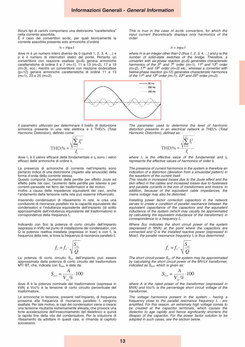
Nel caso di onda con andamento perfettamente sinusoidale(come dovrebbe essere la tensione fornita dagli enti distributori),risulta presente solo l’armonica fondamentale d’ordine 1, che inEuropa ha frequenza di 50 Hz.Applicando una tensione sinusoidale ad un carico, la correntecircolante risulta anche essa sinusoidale solo in presenza dicarichi con “caratteristiche lineari”.In presenza di un carico “non lineare”, l’andamento dellacorrente si discosta dal caso ideale, e una scomposizionesecondo Fourier dell’onda presenterebbe un numero diarmoniche tanto più elevato (in numero e ampiezza), quanto piùè distorta la forma d’onda.L’utilizzo sempre più frequente in ambito industriale di carichinon lineari (inverter, lampade a scarica, saldatrici, alimentatoritipo switching, ecc.) creano elevate distorsioni nella formad’onda della corrente circolante.
THE EFFECT OF HARMONICS IN ELECTRICAL SYSTEMS
A harmonic is defined as one of the components obtained fromthe breakdown of a periodic wave in the Fourier series. Theorder of a harmonic is further defined as the ratio between thefrequency of the harmonic and the fundamental frequency of theperiodic wave considered.
In the case of a perfectly sinusoidal waveform (as shouldcharacterize the voltage supplied by the utility) only thefundamental harmonic of the first order will be present, which inEurope has a frequency of 50 Hz.If a sinusoidal voltage is applied to a load, the circulating currentwill also have a sinusoidal waveform only in the presence ofloads with “linear characteristics”.In the presence of a “non-linear” load the current waveformwill deviate from the ideal pattern and breaking down thewave according to the Fourier theorem will show evidence ofharmonics whose number and amplitude will increase withthe degree of distortion in the current waveform.The increasingly frequent use of non-linear loads inindustrial facilities (inverters, fluorescent lamps, welders,etc.) creates elevated distorsions in the waveform ofcirculating current.
Informazioni Generali - General Information
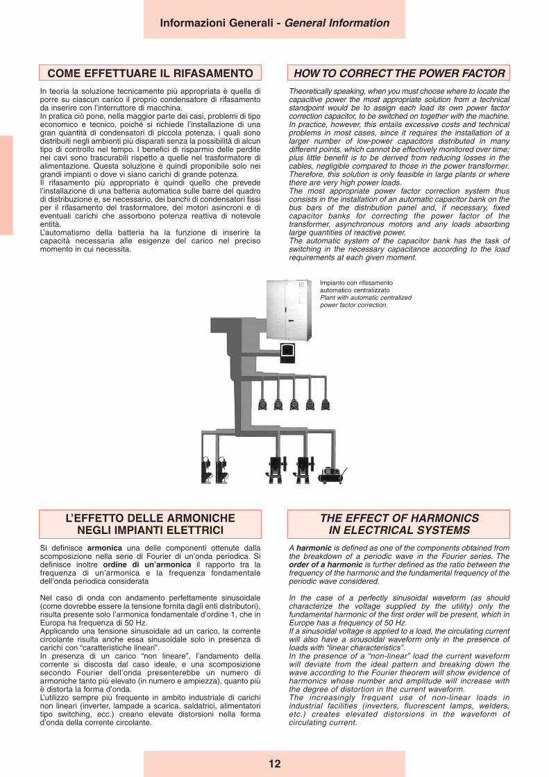
HOW TO CORRECT THE POWER FACTORTheoretically speaking, when you must choose where to locate thecapacitive power the most appropriate solution from a technicalstandpoint would be to assign each load its own power factorcorrection capacitor, to be switched on together with the machine.In practice, however, this entails excessive costs and technicalproblems in most cases, since it requires the installation of alarger number of low-power capacitors distributed in manydifferent points, which cannot be effectively monitored over time;plus little benefit is to be derived from reducing losses in thecables, negligible compared to those in the power transformer.Therefore, this solution is only feasible in large plants or wherethere are very high power loads.The most appropriate power factor correction system thusconsists in the installation of an automatic capacitor bank on thebus bars of the distribution panel and, if necessary, fixedcapacitor banks for correcting the power factor of thetransformer, asynchronous motors and any loads absorbinglarge quantities of reactive power. The automatic system of the capacitor bank has the task ofswitching in the necessary capacitance according to the loadrequirements at each given moment.
COME EFFETTUARE IL RIFASAMENTO
In teoria la soluzione tecnicamente più appropriata è quella diporre su ciascun carico il proprio condensatore di rifasamentoda inserire con l’interruttore di macchina.In pratica ciò pone, nella maggior parte dei casi, problemi di tipoeconomico e tecnico, poiché si richiede l’installazione di unagran quantità di condensatori di piccola potenza, i quali sonodistribuiti negli ambienti più disparati senza la possibilità di alcuntipo di controllo nel tempo. I benefici di risparmio delle perditenei cavi sono trascurabili rispetto a quelle nel trasformatore dialimentazione. Questa soluzione è quindi proponibile solo neigrandi impianti o dove vi siano carichi di grande potenza.Il rifasamento più appropriato è quindi quello che prevedel’installazione di una batteria automatica sulle barre del quadrodi distribuzione e, se necessario, dei banchi di condensatori fissiper il rifasamento del trasformatore, dei motori asincroni e dieventuali carichi che assorbono potenza reattiva di notevoleentità.L’automatismo della batteria ha la funzione di inserire lacapacità necessaria alle esigenze del carico nel precisomomento in cui necessita.
Impianto con rifasamento automatico centralizzatoPlant with automatic centralized power factor correction.
Il parametro utilizzato per determinare il livello di distorsionearmonica presente in una rete elettrica è il THDI% (TotalHarmonic Distorsion), definito come:
dove I1 è il valore efficace della fondamentale e Ik sono i valoriefficaci delle armoniche di ordine k.
La presenza di armoniche di corrente nell’impianto sonopertanto indice di una distorsione (rispetto alla sinusoide) dellaforma d’onda della corrente stessa.Questo comporta l’aumento delle perdite per effetto Joule edeffetto pelle nei cavi, l’aumento delle perdite per isteresi e percorrenti parassite nel ferro dei trasformatori e dei motori.Inoltre a causa delle impedenze equivalenti dei cavi, anchel’andamento della tensione nella rete può esserne influenzato.
Inserendo condensatori di rifasamento in rete, si crea unacondizione di risonanza parallelo tra la capacità equivalente deicondensatori e l’induttanza equivalente dell’impianto (di solitoapprossimabile dall’induttanza equivalente del trasformatore) incorrispondenza della frequenza fr.
Indicando con Scc la potenza di corto circuito dell’impianto(espressa in kVA) nel punto di installazione dei condensatori, conQ la potenza reattiva installata (espressa in kvar) e con f1 lafrequenza della rete, si trova la frequenza di risonanza parallelo fr:
La potenza di corto circuito Scc dell’impianto può essereapprossimata dalla potenza di corto circuito del trasformatoreMT/ BT, che, indicata con Scct, è data da:
dove A è la potenza nominale del trasformatore (espressa inkVA) e Vcc% è la tensione di corto circuito percentuale deltrasformatore.
Le armoniche in tensione, presenti nell’impianto, di frequenzaprossima alla frequenza di risonanza parallelo fr vengonoesaltate. Per tale motivo, ai capi dei condensatori viene a crearsiuna tensione risultante estremamente elevata, che provoca unaforte accelerazione dell’invecchiamento del dielettrico e quindila rapida fine della vita del condensatore. Per la soluzione dirifasamento da adottare in questi casi, si rimanda al capitolosuccessivo.
The parameter used to determine the level of harmonicdistortion presents in an electrical network is THDI% (TotalHarmonic Distortion), defined as:
where I1 is the effective value of the fundamental and Ikrepresents the effective values of harmonics of order k.
The presence of current harmonics in the system is therefore anindication of a distortion (deviation from a sinusoidal pattern) inthe waveform of the current itself.This results in increased losses due to the Joule effect and theskin effect in the cables and increased losses due to hysteresisand parasite currents in the iron of transformers and motors. Inaddition, because of the equivalent cable impedances, themains voltage may also be distorted.
Installing power factor correction capacitors in the networkserves to create a condition of parallel resonance between theequivalent capacitance of the capacitors and the equivalentinductance of the system (which may usually be approximatedby calculating the equivalent inductance of the transformer) incorrespondence to a frequency fr.
Where Scc indicates the short circuit power of the system(expressed in MVA) at the point where the capacitors areconnected and Q is the installed reactive power (expressed inMvar), the parallel resonance frequency fr is thus determined:
The short circuit power Scc of the system may be approximatedby calculating the short circuit power of the MV/LV transformer,indicated as Scct, which is given as:
where A is the rated power of the transformer (expressed inMVA) and Vcc% is the percentage short circuit voltage of thetransformer.
The voltage harmonics present in the system - having afrequency close to the parallel resonance frequency fr - areamplified. For this reason, an extremely high voltage comes tobe created at the capacitor terminals, which causes thedielectric to age rapidly and hence significantly shortens thelifespan of the capacitor. For the power factor solution to beadopted in such cases, see the section below.
13
Alcuni tipi di carichi comportano una distorsione “caratteristica”nella corrente assorbita.È il caso dei convertitori ac/dc, per quali teoricamente lacorrente assorbita presenta solo armoniche d’ordine
h = mp±1
dove m è un numero intero diverso da 0 (quindi 1, 2, 3, 4, ...) ep è il numero di interruttori statici del ponte. Pertanto unconvertitore con reazione esafase (p=6) genera armonichecaratteristiche di ordine 5 e 7 (m=1), 11 e 13 (m=2), 17 e 19(m=3), ecc.; mentre un convertitore con reazione dodecafase(p=12) genera armoniche caratteristiche di ordine 11 e 13(m=1), 23 e 25 (m=2).
This is true in the case of ac/dc converters, for which theinput current theoretically displays only harmonics of theorder
h = mp±1
where m is an integer other than 0 (thus 1, 2, 3, 4, ...) and p is thenumber of solid-state switches of the bridge. Therefore, aconverter with six-phase reaction (p=6) generates characteristicharmonics of the 5th and 7th order (m=1), 11th and 13th order(m=2), 17th and 19th order (m=3) etc., whereas a converter withtwelve-phase reaction (p=12) generates characteristic harmonicsof the 11th and 13th order (m=1), 23rd and 25th order (m=2).
Informazioni Generali - General Information
THDi% THDi%
14
Il calcolo della batteria di condensatori da installare in unimpianto è semplice: noti il cosϕ dell’impianto privo dirifasamento ed il cosϕ che si vuole ottenere, si ricava mediantepochi calcoli la potenza reattiva necessaria al raggiungimentodel fattore di potenza voluto.Il fattore di potenza può essere molto diverso fra due utenze,perché dipende dal tipo di apparecchiature installate e da comesono utilizzate.Ad esempio, i motori asincroni, di gran lunga i più diffusi hannoun fattore di potenza molto variabile in funzione del carico delmotore e del tipo di costruzione dello stesso, fino a valoriestremamente bassi a vuoto.Considerazioni analoghe si possono fare per i trasformatori.Per tutti questi tipi di macchine elettriche si impiega spesso unrifasamento fisso in corrispondenza del motore o deltrasformatore. Altre e notevoli differenze presentano applicazionielettriche come lampade, forni, saldatrici e convertitori.
CALCOLO DELLA POTENZA REATTIVANECESSARIA AL RIFASAMENTO
P = potenza attiva impiantocosϕ0 = cosϕ impianto senza rifasamentocosϕ1 = cosϕ a cui si vuole portare l’impiantoQc = potenza reattiva sistema di rifasamento da installareK = dati cosϕ0 e cosϕ1 si ricava dalla tabella seguente
Qc = P · (tanϕ0 - tanϕ1) = P · K
Qualora non fosse noto il valore di cosϕ che caratterizzal’impianto, si può ricavare tale parametro a partire dai datiriportati sulle fatture di fornitura dell’energia elettrica, oppure lettidirettamente dal contatore.Nota la potenza attiva [kW] P e la potenza reattiva [kVAr] Qdell’impianto, oppure lʼenergia attiva [kWh] e lʼenergia reattiva[kVArh] prelevate, si applica la relazione
Q / P = tanϕ
Il valore di tanϕ così ricavato può essere usato assieme alla tabellaa pagina 15 per calcolare la potenza reattiva del rifasamentonecessario a correggere il fattore di potenza al valore richiesto.
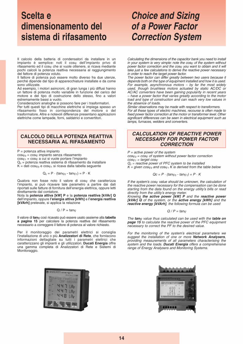
Per il monitoraggio dei parametri elettrici si consiglial’installazione di uno o più Analizzatori di Rete, che fornisconoinformazioni dettagliate su tutti i parametri elettrici checaratterizzano gli impianti e gli utilizzatori. Ducati Energia offreuna gamma completa di Analizzatori di Rete e Sistemi diMonitoraggio.
Calculating the dimensions of the capacitor bank you need to installin your system is very simple: note the cosϕ of the system withoutpower factor correction and the cosϕ you want to obtain and it willtake just a few calculations to derive the reactive power necessaryin order to reach the target power factor.The power factor can differ greatly between two users because itdepends both on the type of equipment installed and how it is used.For example, asynchronous motors – by far the most widelyused, though brushless motors actuated by static AC/DC orAC/AC converters have been gaining popularity in recent years– have a power factor that varies greatly according to the motorload and type of construction and can reach very low values inthe absence of loads. Similar observations may be made with respect to transformers.For all these types of electric machines, recourse is often made tofixed power factor correction at the motor or transformer level. Othersignificant differences can be seen in electrical equipment such aslamps, furnaces, welders and converters.
CALCULATION OF REACTIVE POWERNECESSARY FOR POWER FACTOR
CORRECTIONP = active power of the systemcosϕ0 = cosϕ of system without power factor correctioncosϕ1 = target cosϕQc = reactive power of PFC system to be installedK = given cosϕ0 and cosϕ1 K is derived from the table below
Qc = P · (tanϕ0 - tanϕ1) = P · K
If the system’s cosϕ value should be unknown, the calculation ofthe reactive power necessary for the compensation can be donestarting from the data found on the energy utility’s bills or readdirectly from the utility’s energy meter.Knowing the active power [kW] P and the reactive power[kVAr] Q of the system, or the active energy [kWh] and thereactive energy [kVArh], the following formula can be used
Q / P = tanϕ
The tanϕ value thus calculated can be used with the table onpage 15 to calculate the reactive power of the PFC equipmentnecessary to correct the PF to the desired value.
For the monitoring of the system’s electrical parameters wesuggest the installation of one or more Network Analysers,providing measurements of all parameters characterising thesystem and the loads. Ducati Energia offers a comprehensiverange of Energy Analysers and Monitoring Systems.
Scelta edimensionamento delsistema di rifasamento
Choice and Sizing of a Power FactorCorrection System
15
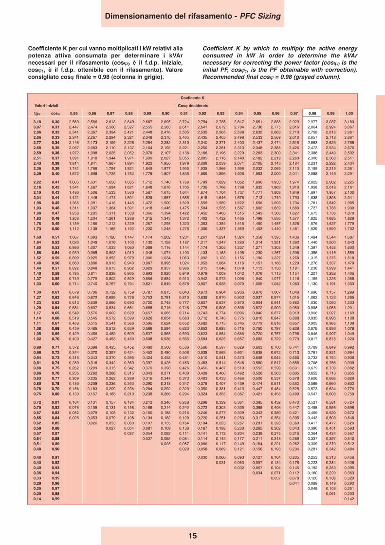
Coefficiente K per cui vanno moltiplicati i kW relativi allapotenza attiva consumata per determinare i kVArnecessari per il rifasamento (cosϕ0 è il f.d.p. iniziale,cosϕ1, è il f.d.p. ottenibile con il rifasamento). Valoreconsigliato cosϕ finale = 0,98 (colonna in grigio).
Coefficient K by which to multiply the active energyconsumed in kW in order to determine the kVArnecessary for correcting the power factor (cosϕ0 is theinitial PF, cosϕ1, is the PF obtainable with correction).Recommended final cosϕ = 0.98 (grayed column).
Coeficente K
Valori iniziali Cosϕ desiderato
tgϕ cosϕ 0,85 0,86 0,87 0,88 0,89 0,90 0,91 0,92 0,93 0,94 0,95 0,96 0,97 0,98 0,99 1,00
3,18 0,30 2,560 2,586 2,613 2,640 2,667 2,695 2,724 2,754 2,785 2,817 2,851 2,888 2,929 2,977 3,037 3,1803,07 0,31 2,447 2,474 2,500 2,527 2,555 2,583 2,611 2,641 2,672 2,704 2,738 2,775 2,816 2,864 2,924 3,0672,96 0,32 2,341 2,367 2,394 2,421 2,448 2,476 2,505 2,535 2,565 2,598 2,632 2,669 2,710 2,758 2,818 2,9612,86 0,33 2,241 2,267 2,294 2,321 2,348 2,376 2,405 2,435 2,465 2,498 2,532 2,569 2,610 2,657 2,718 2,8612,77 0,34 2,146 2,173 2,199 2,226 2,254 2,282 2,310 2,340 2,371 2,403 2,437 2,474 2,515 2,563 2,623 2,7662,68 0,35 2,057 2,083 2,110 2,137 2,164 2,192 2,221 2,250 2,281 2,313 2,348 2,385 2,426 2,473 2,534 2,6762,59 0,36 1,972 1,998 2,025 2,052 2,079 2,107 2,136 2,166 2,196 2,229 2,263 2,300 2,341 2,388 2,449 2,5922,51 0,37 1,891 1,918 1,944 1,971 1,999 2,027 2,055 2,085 2,116 2,148 2,182 2,219 2,260 2,308 2,368 2,5112,43 0,38 1,814 1,841 1,867 1,894 1,922 1,950 1,979 2,008 2,039 2,071 2,105 2,143 2,184 2,231 2,292 2,4342,36 0,39 1,741 1,768 1,794 1,821 1,849 1,877 1,905 1,935 1,966 1,998 2,032 2,069 2,110 2,158 2,219 2,3612,29 0,40 1,672 1,698 1,725 1,752 1,779 1,807 1,836 1,865 1,896 1,928 1,963 2,000 2,041 2,088 2,149 2,291
2,22 0,41 1,605 1,631 1,658 1,685 1,712 1,740 1,769 1,799 1,829 1,862 1,896 1,933 1,974 2,022 2,082 2,2252,16 0,42 1,541 1,567 1,594 1,621 1,648 1,676 1,705 1,735 1,766 1,798 1,832 1,869 1,910 1,958 2,018 2,1612,10 0,43 1,480 1,506 1,533 1,560 1,587 1,615 1,644 1,674 1,704 1,737 1,771 1,808 1,849 1,897 1,957 2,1002,04 0,44 1,421 1,448 1,474 1,501 1,529 1,557 1,585 1,615 1,646 1,678 1,712 1,749 1,790 1,838 1,898 2,0411,98 0,45 1,365 1,391 1,418 1,445 1,472 1,500 1,529 1,559 1,589 1,622 1,656 1,693 1,734 1,781 1,842 1,9851,93 0,46 1,311 1,337 1,364 1,391 1,418 1,446 1,475 1,504 1,535 1,567 1,602 1,639 1,680 1,727 1,788 1,9301,88 0,47 1,258 1,285 1,311 1,338 1,366 1,394 1,422 1,452 1,483 1,515 1,549 1,586 1,627 1,675 1,736 1,8781,83 0,48 1,208 1,234 1,261 1,288 1,315 1,343 1,372 1,402 1,432 1,465 1,499 1,536 1,577 1,625 1,685 1,8281,78 0,49 1,159 1,186 1,212 1,239 1,267 1,295 1,323 1,353 1,384 1,416 1,450 1,487 1,528 1,576 1,637 1,7791,73 0,50 1,112 1,139 1,165 1,192 1,220 1,248 1,276 1,306 1,337 1,369 1,403 1,440 1,481 1,529 1,590 1,732
1,69 0,51 1,067 1,093 1,120 1,147 1,174 1,202 1,231 1,261 1,291 1,324 1,358 1,395 1,436 1,484 1,544 1,6871,64 0,52 1,023 1,049 1,076 1,103 1,130 1,158 1,187 1,217 1,247 1,280 1,314 1,351 1,392 1,440 1,500 1,6431,60 0,53 0,980 1,007 1,033 1,060 1,088 1,116 1,144 1,174 1,205 1,237 1,271 1,308 1,349 1,397 1,458 1,6001,56 0,54 0,939 0,965 0,992 1,019 1,046 1,074 1,103 1,133 1,163 1,196 1,230 1,267 1,308 1,356 1,416 1,5591,52 0,55 0,899 0,925 0,952 0,979 1,006 1,034 1,063 1,092 1,123 1,156 1,190 1,227 1,268 1,315 1,376 1,5181,48 0,56 0,860 0,886 0,913 0,940 0,967 0,995 1,024 1,053 1,084 1,116 1,151 1,188 1,229 1,276 1,337 1,4791,44 0,57 0,822 0,848 0,875 0,902 0,929 0,957 0,986 1,015 1,046 1,079 1,113 1,150 1,191 1,238 1,299 1,4411,40 0,58 0,785 0,811 0,838 0,865 0,892 0,920 0,949 0,979 1,009 1,042 1,076 1,113 1,154 1,201 1,262 1,4051,37 0,59 0,749 0,775 0,802 0,829 0,856 0,884 0,913 0,942 0,973 1,006 1,040 1,077 1,118 1,165 1,226 1,3681,33 0,60 0,714 0,740 0,767 0,794 0,821 0,849 0,878 0,907 0,938 0,970 1,005 1,042 1,083 1,130 1,191 1,333
1,30 0,61 0,679 0,706 0,732 0,759 0,787 0,815 0,843 0,873 0,904 0,936 0,970 1,007 1,048 1,096 1,157 1,2991,27 0,62 0,646 0,672 0,699 0,726 0,753 0,781 0,810 0,839 0,870 0,903 0,937 0,974 1,015 1,062 1,123 1,2651,23 0,63 0,613 0,639 0,666 0,693 0,720 0,748 0,777 0,807 0,837 0,870 0,904 0,941 0,982 1,030 1,090 1,2331,20 0,64 0,581 0,607 0,634 0,661 0,688 0,716 0,745 0,775 0,805 0,838 0,872 0,909 0,950 0,998 1,058 1,2011,17 0,65 0,549 0,576 0,602 0,629 0,657 0,685 0,714 0,743 0,774 0,806 0,840 0,877 0,919 0,966 1,027 1,1691,14 0,66 0,519 0,545 0,572 0,599 0,626 0,654 0,683 0,712 0,743 0,775 0,810 0,847 0,888 0,935 0,996 1,1381,11 0,67 0,488 0,515 0,541 0,568 0,596 0,624 0,652 0,682 0,713 0,745 0,779 0,816 0,857 0,905 0,966 1,1081,08 0,68 0,459 0,485 0,512 0,539 0,566 0,594 0,623 0,652 0,683 0,715 0,750 0,787 0,828 0,875 0,936 1,0781,05 0,69 0,429 0,456 0,482 0,509 0,537 0,565 0,593 0,623 0,654 0,686 0,720 0,757 0,798 0,846 0,907 1,0491,02 0,70 0,400 0,427 0,453 0,480 0,508 0,536 0,565 0,594 0,625 0,657 0,692 0,729 0,770 0,817 0,878 1,020
0,99 0,71 0,372 0,398 0,425 0,452 0,480 0,508 0,536 0,566 0,597 0,629 0,663 0,700 0,741 0,789 0,849 0,9920,96 0,72 0,344 0,370 0,397 0,424 0,452 0,480 0,508 0,538 0,569 0,601 0,635 0,672 0,713 0,761 0,821 0,9640,94 0,73 0,316 0,343 0,370 0,396 0,424 0,452 0,481 0,510 0,541 0,573 0,608 0,645 0,686 0,733 0,794 0,9360,91 0,74 0,289 0,316 0,342 0,369 0,397 0,425 0,453 0,483 0,514 0,546 0,580 0,617 0,658 0,706 0,766 0,9090,88 0,75 0,262 0,289 0,315 0,342 0,370 0,398 0,426 0,456 0,487 0,519 0,553 0,590 0,631 0,679 0,739 0,8820,86 0,76 0,235 0,262 0,288 0,315 0,343 0,371 0,400 0,429 0,460 0,492 0,526 0,563 0,605 0,652 0,713 0,8550,83 0,77 0,209 0,235 0,262 0,289 0,316 0,344 0,373 0,403 0,433 0,466 0,500 0,537 0,578 0,626 0,686 0,8290,80 0,78 0,183 0,209 0,236 0,263 0,290 0,318 0,347 0,376 0,407 0,439 0,474 0,511 0,552 0,599 0,660 0,8020,78 0,79 0,156 0,183 0,209 0,236 0,264 0,292 0,320 0,350 0,381 0,413 0,447 0,484 0,525 0,573 0,634 0,7760,75 0,80 0,130 0,157 0,183 0,210 0,238 0,266 0,294 0,324 0,355 0,387 0,421 0,458 0,499 0,547 0,608 0,750
0,72 0,81 0,104 0,131 0,157 0,184 0,212 0,240 0,268 0,298 0,329 0,361 0,395 0,432 0,473 0,521 0,581 0,7240,70 0,82 0,078 0,105 0,131 0,158 0,186 0,214 0,242 0,272 0,303 0,335 0,369 0,406 0,447 0,495 0,556 0,6980,67 0,83 0,052 0,079 0,105 0,132 0,160 0,188 0,216 0,246 0,277 0,309 0,343 0,380 0,421 0,469 0,530 0,6720,65 0,84 0,026 0,053 0,079 0,106 0,134 0,162 0,190 0,220 0,251 0,283 0,317 0,354 0,395 0,443 0,503 0,6460,62 0,85 0,026 0,053 0,080 0,107 0,135 0,164 0,194 0,225 0,257 0,291 0,328 0,369 0,417 0,477 0,6200,59 0,86 0,027 0,054 0,081 0,109 0,138 0,167 0,198 0,230 0,265 0,302 0,343 0,390 0,451 0,5930,57 0,87 0,027 0,054 0,082 0,111 0,141 0,172 0,204 0,238 0,275 0,316 0,364 0,424 0,5670,54 0,88 0,027 0,055 0,084 0,114 0,145 0,177 0,211 0,248 0,289 0,337 0,397 0,5400,51 0,89 0,028 0,057 0,086 0,117 0,149 0,184 0,221 0,262 0,309 0,370 0,5120,48 0,90 0,029 0,058 0,089 0,121 0,156 0,193 0,234 0,281 0,342 0,484
0,46 0,91 0,030 0,060 0,093 0,127 0,164 0,205 0,253 0,313 0,4560,43 0,92 0,031 0,063 0,097 0,134 0,175 0,223 0,284 0,4260,40 0,93 0,032 0,067 0,104 0,145 0,192 0,253 0,3950,36 0,94 0,034 0,071 0,112 0,160 0,220 0,3630,33 0,95 0,037 0,078 0,126 0,186 0,3290,29 0,96 0,041 0,089 0,149 0,2920,25 0,97 0,048 0,108 0,2510,20 0,98 0,061 0,2030,14 0,99 0,142
Dimensionamento del rifasamento - PFC Sizing
16
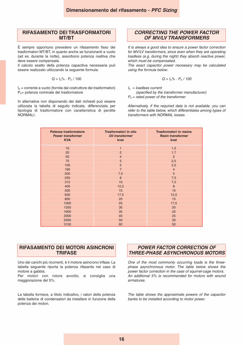
Potenza trasformatore Trasformatori in olio Trasformatori in resinaPower transformer Oil transformer Resin transformer
KVA kvar kvar
10 1 1,520 2 1,750 4 275 5 2,5100 5 2,5160 7 4200 7,5 5250 8 7,5315 10 7,5400 12,5 8500 15 10630 17,5 12,5800 20 151000 25 17,51250 30 201600 35 222000 40 252500 50 353150 60 50
RIFASAMENTO DEI TRASFORMATORIMT/BT
È sempre opportuno prevedere un rifasamento fisso deitrasformatori MT/BT, in quanto anche se funzionanti a vuoto(ad es. durante la notte), assorbono potenza reattiva chedeve essere compensata.Il calcolo esatto della potenza capacitiva necessaria puòessere realizzato utilizzando la seguente formula:
Q = Io% · Pn / 100
Io = corrente a vuoto (fornita dal costruttore dei trasformatori)Pn= potenza nominale del trasformatore
In alternativa non disponendo dei dati richiesti può essereutilizzata la tabella di seguito indicata, differenziata pertipologia di trasformatore con caratteristica di perditeNORMALI.
CORRECTING THE POWER FACTOR OF MV/LV TRANSFORMERS
It is always a good idea to ensure a power factor correctionfor MV/LV transformers, since even when they are operatingloadless (e.g. during the night) they absorb reactive power,which must be compensated.The exact capacitor power necessary may be calculatedusing the formula below:
Q = Io% · Pn / 100
Io = loadless current (specified by the transformer manufacturer)
Pn = rated power of the transformer
Alternatively, if the required data is not available, you canrefer to the table below, which differentiates among types oftransformers with NORMAL losses.
Dimensionamento del rifasamento - PFC Sizing
RIFASAMENTO DEI MOTORI ASINCRONITRIFASE
Uno dei carichi più ricorrenti, è il motore asincrono trifase. Latabella seguente riporta la potenza rifasante nel caso dimotore a gabbia.Per motori con rotore avvolto, si consiglia unamaggiorazione del 5%.
POWER FACTOR CORRECTION OF THREE-PHASE ASYNCHRONOUS MOTORS
One of the most commonly occurring loads is the three-phase asynchronous motor. The table below shows thepower factor correction in the case of squirrel-cage motors.An additional 5% is recommended for motors with woundarmatures.
La tabella fornisce, a titolo indicativo, i valori della potenzadelle batterie di condensatori da installare in funzione dellapotenza dei motori.
The table shows the approximate powers of the capacitorbanks to be installed according to motor power.
17
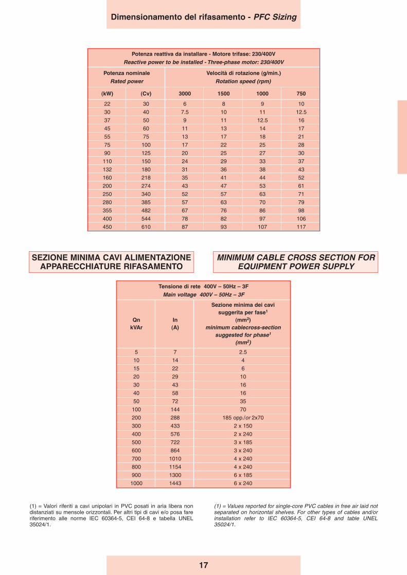
(1) = Valori riferiti a cavi unipolari in PVC posati in aria libera nondistanziati su mensole orizzontali. Per altri tipi di cavi e/o posa fareriferimento alle norme IEC 60364-5, CEI 64-8 e tabella UNEL35024/1.
(1) = Values reported for single-core PVC cables in free air laid notseparated on horizontal shelves. For other types of cables and/orinstallation refer to IEC 60364-5, CEI 64-8 and table UNEL35024/1.
Tensione di rete 400V – 50Hz – 3F
Main voltage 400V – 50Hz – 3F
Sezione minima dei cavisuggerita per fase1
Qn In (mm2)kVAr (A) minimum cablecross-section
suggested for phase1
(mm2)
5 7 2.5
10 14 4
15 22 6
20 29 10
30 43 16
40 58 16
50 72 35
100 144 70
200 288 185 opp./or 2x70
300 433 2 x 150
400 576 2 x 240
500 722 3 x 185
600 864 3 x 240
700 1010 4 x 240
800 1154 4 x 240
900 1300 6 x 185
1000 1443 6 x 240
Dimensionamento del rifasamento - PFC Sizing
Potenza reattiva da installare - Motore trifase: 230/400V
Reactive power to be installed - Three-phase motor: 230/400V
Potenza nominale Velocità di rotazione (g/min.)
Rated power Rotation speed (rpm)
(kW) (Cv) 3000 1500 1000 750
22 30 6 8 9 10
30 40 7.5 10 11 12.5
37 50 9 11 12.5 16
45 60 11 13 14 17
55 75 13 17 18 21
75 100 17 22 25 28
90 125 20 25 27 30
110 150 24 29 33 37
132 180 31 36 38 43
160 218 35 41 44 52
200 274 43 47 53 61
250 340 52 57 63 71
280 385 57 63 70 79
355 482 67 76 86 98
400 544 78 82 97 106
450 610 87 93 107 117
SEZIONE MINIMA CAVI ALIMENTAZIONEAPPARECCHIATURE RIFASAMENTO
MINIMUM CABLE CROSS SECTION FOREQUIPMENT POWER SUPPLY
18
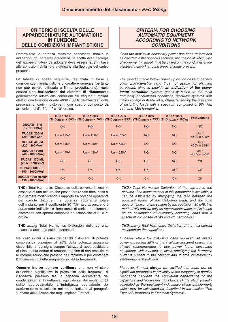
CRITERIO DI SCELTA DELLEAPPARECCHIATURE AUTOMATICHE
IN FUNZIONE DELLE CONDIZIONI IMPIANTISTICHE
Determinata la potenza massima necessaria tramite leindicazioni dei paragrafi precedenti, la scelta della tipologiadell’apparecchiatura da adottare deve essere fatte in basealle condizioni della rete elettrica e alle tipologie del caricopresenti.
La tabella di scelta seguente, realizzata in base aconsiderazioni impiantistiche di carattere generale (pertantonon può essere utilizzata a fini di progettazione), vuoleessere una indicazione del sistema di rifasamentogeneralmente adatto alle condizioni più frequenti: impiantielettrici con tensione di rete 400V - 50Hz caratterizzati dallapresenza di carichi distorcenti con spettro composto daarmoniche di 5°, 7°, 11° e 13° ordine.
CRITERIA FOR CHOOSING AUTOMATIC EQUIPMENT
ACCORDING TO NETWORK CONDITIONS
Once the maximum necessary power has been determinedas directed in the previous sections, the choice of which typeof equipment to adopt must be based on the conditions of theelectrical network and the types of loads present.
The selection table below, drawn up on the basis of generalplant characteristics (and thus not usable for planningpurposes), aims to provide an indication of the powerfactor correction system generally suited to the mostfrequently encountered conditions; electrical systems withmains voltage of 400V-50Hz, characterized by the presenceof distorting loads with a spectrum composed of 5th, 7th,11th and 13th harmonics.
- THDI: Total Harmonics Distorsion della corrente in rete. Inassenza di una misura che possa fornire tale dato, esso sipuò stimare moltiplicando il rapporto tra potenza apparentedei carichi distorcenti e potenza apparente totaledell’impianto per il coefficiente 30 (NB: tale assunzione èpuramente indicativa e tiene conto di carichi mediamentedistorcenti con spettro composto da armoniche di 5° e 7°ordine.
- THDI (MAXC): Total Harmonics Distorsion della correntemassima accettata sui condensatori.
Nel caso in cui vi siano dei carichi distorcenti di potenzacomplessiva superiore al 25% della potenza apparentedisponibile, si consiglia sempre l’utilizzo di apparecchiaturedi rifasamento dotate di reattanze, al fine di non amplificarele correnti armoniche presenti nell’impianto e per contenerel’inquinamento elettromagnetico in bassa frequenza.
Occorre inoltre sempre verificare che non vi sianoarmoniche significative in prossimità della frequenza dirisonanza parallelo tra la capacità equivalente deicondensatori e l’induttanza equivalente dell’impianto (disolito approssimabile all’induttanza equivalente deltrasformatore) calcolabile nel modo indicato al paragrafo“L’effetto delle Armoniche negli Impianti Elettrici”.
- THDI: Total Harmonics Distortion of the current in thenetwork. If no measurement of this parameter is available, itcan be estimated by multiplying the ratio between theapparent power of the distorting loads and the totalapparent power of the system by the coefficient 30 (NB: thismethod will provide only an approximate value and is basedon an assumption of averagely distorting loads with aspectrum composed of 5th and 7th harmonics).
- THDI (MAXC): Total Harmonics Distortion of the max currentaccepted on the capacitors.
In cases where the distorting loads represent an overallpower exceeding 25% of the available apparent power, it isalways recommended to use power factor correctionequipment with reactors to avoid amplifying the harmoniccurrents present in the network and to limit low-frequencyelectromagnetic pollution.
Moreover, it must always be verified that there are nosignificant harmonics in proximity to the frequency of parallelresonance between the equivalent capacitance of thecapacitors and equivalent inductance of the plant (usuallyestimated as the equivalent inductance of the transformer),which may be calculated as described in the section “TheEffect of Harmonics in Electrical Systems”.
Dimensionamento del rifasamento - PFC Sizing
THD < 12%(THDI(MAXC) < 50%)
THD < 20%(THDI(MAXC) < 70%)
THD < 27%(THDI(MAXC) < 85%)
THD < 80%(THDI(MAXC) < 95%)
THD < 100%(THDI (MAXC) < 100%)
Fotovoltaico
DUCATI 18-M(5 - 17,5kVAr)
OK NO NO NO NO NO
DUCATI 200-M(20 - 200kVAr)
Un = 415V Un = 450V Un = 525V NO NOUn =
450V o 525V
DUCATI 400-M(220 - 400kVAr)
Un = 415V Un = 450V Un = 525V NO NOUn =
450V o 525V
DUCATI 1600R(240 - 1600kVAr)
Un = 415V Un = 450V Un = 525V NO NOUn =
450V o 525V
DUCATI 170-ML(25,5 - 170kVAr)
OK OK OK OK NO OK
DUCATI 1000-RL(150 - 1000kVAr)
OK OK OK OK NO OK
DUCATI 1000-RL/HP(150 - 1000kVAr)
OK OK OK OK OK OK
19
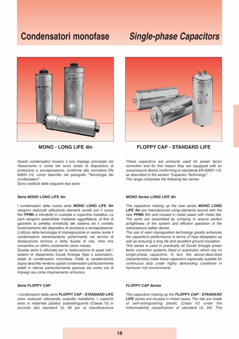
Questi condensatori trovano il loro impiego principale nelrifasamento e come tali sono dotati di dispositivo diprotezione a sovrapressione, conforme alle normative EN60831-1/2, come descritto nel paragrafo “Tecnologia deicondensatori”.Sono costituiti dalle seguenti due serie:
Serie MONO LONG LIFE 4In
I condensatori della nuova serie MONO LONG LIFE 4Invengono realizzati utilizzando elementi avvolti con il nuovofilm PPMh e introdotto in custodie e coperchio metallico. Leparti vengono assemblate mediante aggraffatura, al fine digarantire la perfetta ermeticità del sistema ed il correttofunzionamento del dispositivo di sicurezza a sovrapressione.L’utilizzo della tecnologia di impregnazione in resina rende ilcondensatore estremamente performante nei termini didissipazione termica e della durata di vita, oltre checonsentire un ottimo isolamento verso massa.Questa serie è utilizzata per la realizzazione di quasi tutti isistemi di rifasamento Ducati Energia (fissi o automatici),dotati di condensatori monofase. Infatti le caratteristichesopra descritte rendono questi condensatori particolarmenteadatti in utenze particolarmente gravose sia come ore diimpiego sia come inquinamento armonico.
Serie FLOPPY CAP
I condensatori della serie FLOPPY CAP - STANDARD LIFEsono realizzati utilizzando custodie metalliche. I coperchisono in materiale plastico autoestinguente (Classe V2 inaccordo allo standard UL 94 per la classificazione
These capacitors are primarily used for power factorcorrection and for this reason they are equipped with anoverpressure device conforming to standards EN 60831-1/2,as described in the section “Capacitor Technology”.The range comprises the following two series:
MONO Series LONG LIFE 4In
The capacitors making up the new series MONO LONGLIFE 4In are manufactured using elements wound with thenew PPMh film and housed in metal cases with metal lids.The parts are assembled by crimping to ensure perfectairtightness of the system and efficient operation of theoverpressure safety device.The use of resin impregnation technology greatly enhancesthe capacitor’s performance in terms of heat dissipation aswell as ensuring a long life and excellent ground insulation.This series is used in practically all Ducati Energia powerfactor correction systems (fixed or automatic) which rely onsingle-phase capacitors. In fact, the above-describedcharacteristics make these capacitors especially suitable forcontinuous duty under highly demanding conditions inharmonic rich environments.
FLOPPY CAP Series
The capacitors making up the FLOPPY CAP - STANDARDLIFE series are housed in metal cases. The lids are madeof self-extinguishing plastic (Class V2 under theinflammability classification of standard UL 94). The
Condensatori monofase Single-phase Capacitors
MONO - LONG LIFE 4In FLOPPY CAP - STANDARD LIFE
20
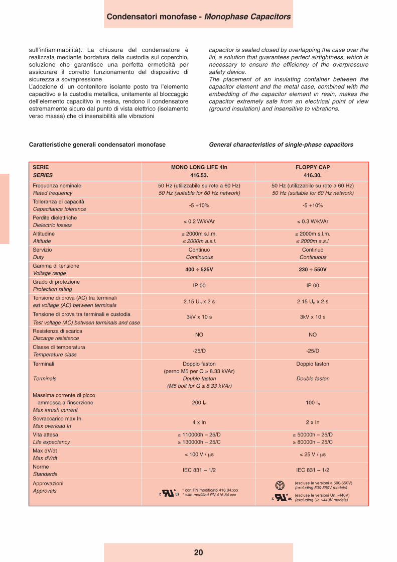
SERIE MONO LONG LIFE 4In FLOPPY CAP
SERIES 416.53. 416.30.
Frequenza nominale 50 Hz (utilizzabile su rete a 60 Hz) 50 Hz (utilizzabile su rete a 60 Hz)Rated frequency 50 Hz (suitable for 60 Hz network) 50 Hz (suitable for 60 Hz network)
Tolleranza di capacità-5 +10% -5 +10%
Capacitance tolerance
Perdite dielettriche≤ 0.2 W/kVAr ≤ 0.3 W/kVAr
Dielectric losses
Altitudine ≤ 2000m s.l.m. ≤ 2000m s.l.m.Altitude ≤ 2000m a.s.l. ≤ 2000m a.s.l.
Servizio Continuo ContinuoDuty Continuous Continuous
Gamma di tensione400 ÷ 525V 230 ÷ 550V
Voltage range
Grado di protezioneIP 00 IP 00
Protection rating
Tensione di prova (AC) tra terminali2.15 Un x 2 s 2.15 Un x 2 s
est voltage (AC) between terminals
Tensione di prova tra terminali e custodia 3kV x 10 s 3kV x 10 sTest voltage (AC) between terminals and case
Resistenza di scaricaNO NO
Discarge resistence
Classe di temperatura-25/D -25/D
Temperature class
Terminali Doppio faston Doppio faston(perno M5 per Q ≥ 8.33 kVAr)
Terminals Double faston Double faston(M5 bolt for Q ≥ 8.33 kVAr)
Massima corrente di piccoammessa all’inserzione 200 In 100 In
Max inrush current
Sovraccarico max In4 x In 2 x In
Max overload In
Vita attesa ≥ 110000h – 25/D ≥ 50000h – 25/DLife expectancy ≥ 130000h – 25/C ≥ 80000h – 25/C
Max dV/dt≤ 100 V / μs ≤ 25 V / μs
Max dV/dt
NormeIEC 831 – 1/2 IEC 831 – 1/2
Standards
ApprovazioniApprovals
(escluse le versioni a 500-550V)(excluding 500-550V models)
(escluse le versioni Un >440V)(excluding Un >440V models)
General characteristics of single-phase capacitorsCaratteristiche generali condensatori monofase
sull’infiammabilità). La chiusura del condensatore èrealizzata mediante bordatura della custodia sul coperchio,soluzione che garantisce una perfetta ermeticità perassicurare il corretto funzionamento del dispositivo disicurezza a sovrapressioneL’adozione di un contenitore isolante posto tra l’elementocapacitivo e la custodia metallica, unitamente al bloccaggiodell’elemento capacitivo in resina, rendono il condensatoreestremamente sicuro dal punto di vista elettrico (isolamentoverso massa) che di insensibilità alle vibrazioni
capacitor is sealed closed by overlapping the case over thelid, a solution that guarantees perfect airtightness, which isnecessary to ensure the efficiency of the overpressuresafety device.The placement of an insulating container between thecapacitor element and the metal case, combined with theembedding of the capacitor element in resin, makes thecapacitor extremely safe from an electrical point of view(ground insulation) and insensitive to vibrations.
Condensatori monofase - Monophase Capacitors
* con PN modificato 416.84.xxx* with modified PN 416.84.xxx
21
MONO LONG LIFE 4In
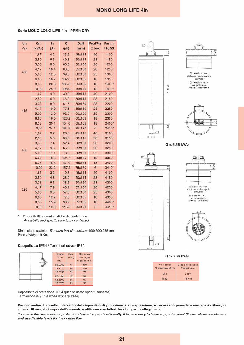
Serie MONO LONG LIFE 4In - PPMh DRY
Per consentire il corretto intervento del dispositivo di protezione a sovrapressione, è necessario prevedere uno spazio libero, dialmeno 30 mm, al di sopra dellʼelemento e utilizzare conduttori flessibili per il collegamento.
To enable the overpressure protection device to operate efficiently, it is necessary to leave a gap of at least 30 mm. above the elementand use flexible leads for the connection.
Q > 6.66 kVAr
Q ≤ 6.66 kVAr
Un Qn In C DxH Pezzi/Pcs Part n.
(V) (kVAr) (A) (μF) (mm) x box 416.53.
1,67 4,2 33,2 45x115 40 1100
2,50 6,3 49,8 50x115 28 1150
3,33 8,3 66,3 50x150 28 1200
4,17 10,4 83,0 55x150 28 1250400
5,00 12,5 99,5 60x150 25 1300
6,66 16,7 132,6 60x165 18 1350
8,33 20,8 165,8 65x165 18 1400*
10,00 25,0 198,9 75x170 12 1410*
1,67 4,0 30,9 45x115 40 2100
2,50 6,0 46,2 50x115 28 2150
3,33 8,0 61,6 50x150 28 2200
4154,17 10,0 77,1 55x150 28 2250
5,00 12,0 92,5 60x150 25 2300
6,66 16,0 123,2 60x165 18 2350
8,33 20,1 154,0 65x165 18 2400*
10,00 24,1 184,8 75x170 6 2410*
1,67 3,7 26,3 45x115 40 3100
2,50 5,6 39,3 50x115 28 3150
3,33 7,4 52,4 50x150 28 3200
4504,17 9,3 65,6 55x150 28 3250
5,00 11,1 78,6 60x150 25 3300
6,66 18,8 104,7 60x165 18 3350
8,33 18,5 131,0 65x165 18 3400*
10,00 22,2 157,2 75x170 6 3410*
1,67 3,2 19,3 45x115 40 4100
2,50 4,8 28,9 50x115 28 4150
3,33 6,3 38,5 50x150 28 4200
5254,17 7,9 48,2 55x150 28 4250
5,00 9,5 57,8 60x150 25 4300
6,66 12,7 77,0 60x165 18 4350
8,33 15,9 96,2 65x165 18 4400*
10,00 19,0 115,5 75x170 6 4410*
* = Disponibilità e caratteristiche da confermareAvailability and specification to be confirmed
Dimensione scatole / Standard box dimensions: 195x390x255 mmPeso / Weight: 9 Kg.
Viti e codoli Coppia di fissaggioScrews and studs Fixing torque
M 5 3 Nm
M 12 11 Nm
Codice diam. ConfezioniCode (mm) Packages316. n. pz. per box
23.0860 45 100
23.1070 50 200
52.3350 55 72
52.3355 60 60
52.3360 65 60
52.3370 75 36
Cappellotto IP54 / Terminal cover IP54
Cappellotto di protezione (IP54 quando usato opportunamente)Terminal cover (IP54 when properly used)

22
FLOPPY CAP
Un Qn In C DxH Pezzi/Pcs Part n. Dim.
(V) (kVAr) (A) (μF) (mm) x box 416.30. box
2300,83 3,6 50,2 45x122 25 0764 A
1,67 7,2 100 60x137 25 0564 A
1,67 4,2 33,2 50x122 25 3964 B
4002,50 6,3 50 55x132 25 4064 A
3,33 8,3 66,3 60x137 25 3764 A
4,17 10,4 83 60x137 25 5064 A
1,67 4,0 30,9 50x122 25 3264 A
4152,50 6,0 46,2 55x132 25 3464 A
3,33 8,0 61,6 60x137 25 3664 A
4,17 10,0 77,1 60x137 25 5264 A
1,67 3,7 26,3 50x132 25 6464 A
4502,50 5,6 39,3 55x132 25 6164 A
3,33 7,4 52,4 60x137 25 6264 A
4,17 9,3 65,6 60x137 25 5364 A
1,67 3,3 21,3 50x132 25 8664 A
5002,50 5 31,8 55x132 25 7664 A
3,33 6,6 42,4 60x137 25 7964 A
4,17 8,3 53,1 60x137 25 5664 A
1,67 3 17,6 45x132 25 8164 B
5502,50 4,5 26,3 55x132 25 7464 A
3,33 6,1 35,1 60x137 25 7764 A
4,17 7,6 43,9 60x137 25 8064 A
Serie FLOPPY CAP - PPM DRY
Per consentire il corretto intervento del dispositivo di protezione a sovrapressione, è necessario prevedere uno spazio libero, dialmeno 20 mm, al di sopra dellʼelemento e utilizzare conduttori flessibili per il collegamento.
To enable the overpressure protection device to operate efficiently, it is necessary to leave a gap of at least 20 mm. above the elementand use flexible leads for the connection.
Dimensione scatole / Standard box dimensions: A = 195 x 390 x 255 mm.B = 195 x 390 x 200 mm.
Peso / Weight: 9 Kg.
Funzionamento del dispositivo a sovrappressione.Operation of the overpressure protection device.
Viti e codoli Coppia di fissaggioScrews and studs Fixing torque
M12 11 Nm
Codice diam. ConfezioniCode (mm) Packages316. n. pz. per box
23.0860 45 100
23.1070 50 200
52.3350 55 72
52.3355 60 60
Cappellotto IP54 / Terminal cover IP54
Cappellotto di protezione (IP54 quando usato opportunamente)Terminal cover (IP54 when properly used)
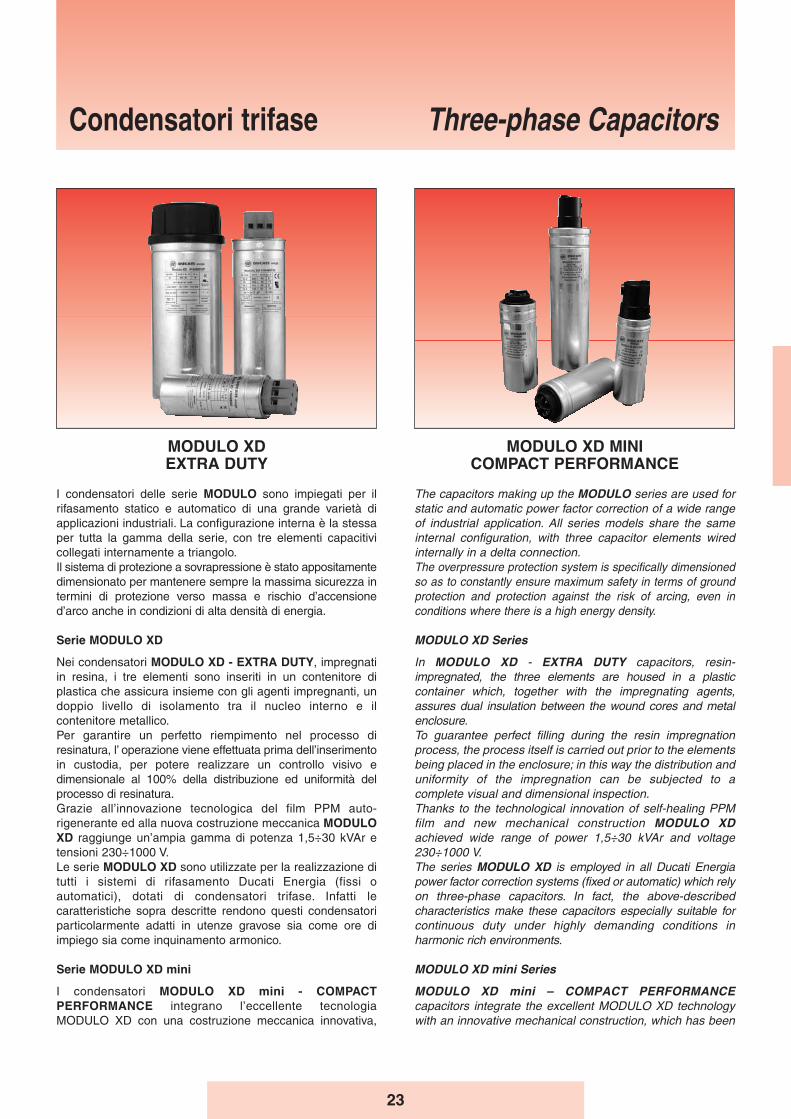
23
Three-phase Capacitors
I condensatori delle serie MODULO sono impiegati per ilrifasamento statico e automatico di una grande varietà diapplicazioni industriali. La configurazione interna è la stessaper tutta la gamma della serie, con tre elementi capacitivicollegati internamente a triangolo.Il sistema di protezione a sovrapressione è stato appositamentedimensionato per mantenere sempre la massima sicurezza intermini di protezione verso massa e rischio d’accensioned’arco anche in condizioni di alta densità di energia.
Serie MODULO XD
Nei condensatori MODULO XD - EXTRA DUTY, impregnatiin resina, i tre elementi sono inseriti in un contenitore diplastica che assicura insieme con gli agenti impregnanti, undoppio livello di isolamento tra il nucleo interno e ilcontenitore metallico.Per garantire un perfetto riempimento nel processo diresinatura, l’ operazione viene effettuata prima dell’inserimentoin custodia, per potere realizzare un controllo visivo edimensionale al 100% della distribuzione ed uniformità delprocesso di resinatura.Grazie all’innovazione tecnologica del film PPM auto-rigenerante ed alla nuova costruzione meccanica MODULOXD raggiunge un’ampia gamma di potenza 1,5÷30 kVAr etensioni 230÷1000 V.Le serie MODULO XD sono utilizzate per la realizzazione ditutti i sistemi di rifasamento Ducati Energia (fissi oautomatici), dotati di condensatori trifase. Infatti lecaratteristiche sopra descritte rendono questi condensatoriparticolarmente adatti in utenze gravose sia come ore diimpiego sia come inquinamento armonico.
Serie MODULO XD mini
I condensatori MODULO XD mini - COMPACTPERFORMANCE integrano l’eccellente tecnologiaMODULO XD con una costruzione meccanica innovativa,
The capacitors making up the MODULO series are used forstatic and automatic power factor correction of a wide rangeof industrial application. All series models share the sameinternal configuration, with three capacitor elements wiredinternally in a delta connection.The overpressure protection system is specifically dimensionedso as to constantly ensure maximum safety in terms of groundprotection and protection against the risk of arcing, even inconditions where there is a high energy density.
MODULO XD Series
In MODULO XD - EXTRA DUTY capacitors, resin-impregnated, the three elements are housed in a plasticcontainer which, together with the impregnating agents,assures dual insulation between the wound cores and metalenclosure.To guarantee perfect filling during the resin impregnationprocess, the process itself is carried out prior to the elementsbeing placed in the enclosure; in this way the distribution anduniformity of the impregnation can be subjected to acomplete visual and dimensional inspection.Thanks to the technological innovation of self-healing PPMfilm and new mechanical construction MODULO XDachieved wide range of power 1,5÷30 kVAr and voltage230÷1000 V.The series MODULO XD is employed in all Ducati Energiapower factor correction systems (fixed or automatic) which relyon three-phase capacitors. In fact, the above-describedcharacteristics make these capacitors especially suitable forcontinuous duty under highly demanding conditions inharmonic rich environments.
MODULO XD mini Series
MODULO XD mini – COMPACT PERFORMANCEcapacitors integrate the excellent MODULO XD technologywith an innovative mechanical construction, which has been
Condensatori trifase
MODULO XDEXTRA DUTY
MODULO XD MINICOMPACT PERFORMANCE
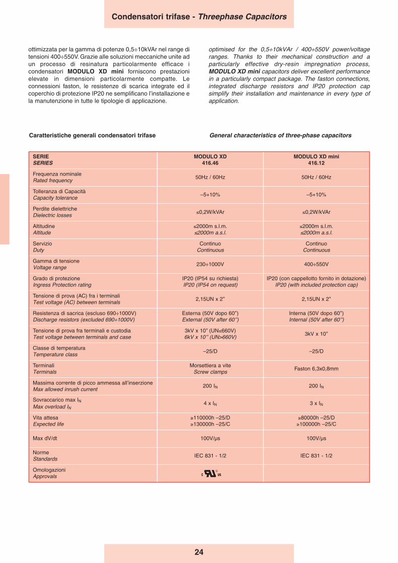
24
Caratteristiche generali condensatori trifase General characteristics of three-phase capacitors
Condensatori trifase - Threephase Capacitors
ottimizzata per la gamma di potenze 0,5÷10kVAr nel range ditensioni 400÷550V. Grazie alle soluzioni meccaniche unite adun processo di resinatura particolarmente efficace icondensatori MODULO XD mini forniscono prestazionielevate in dimensioni particolarmente compatte. Leconnessioni faston, le resistenze di scarica integrate ed ilcoperchio di protezione IP20 ne semplificano l’installazione ela manutenzione in tutte le tipologie di applicazione.
optimised for the 0,5÷10kVAr / 400÷550V power/voltageranges. Thanks to their mechanical construction and aparticularly effective dry-resin impregnation process,MODULO XD mini capacitors deliver excellent performancein a particularly compact package. The faston connections,integrated discharge resistors and IP20 protection capsimplify their installation and maintenance in every type ofapplication.
SERIESERIES
MODULO XD416.46
MODULO XD mini416.12
Frequenza nominaleRated frequency
50Hz / 60Hz 50Hz / 60Hz
Tolleranza di CapacitàCapacity tolerance
–5+10% –5+10%
Perdite dielettricheDielectric losses
≤0,2W/kVAr ≤0,2W/kVAr
AltitudineAltitude
≤2000m s.l.m.≤2000m a.s.l.
≤2000m s.l.m.≤2000m a.s.l.
ServizioDuty
ContinuoContinuous
ContinuoContinuous
Gamma di tensioneVoltage range
230÷1000V 400÷550V
Grado di protezioneIngress Protection rating
IP20 (IP54 su richiesta)IP20 (IP54 on request)
IP20 (con cappellotto fornito in dotazione)IP20 (with included protection cap)
Tensione di prova (AC) fra i terminaliTest voltage (AC) between terminals
2,15UN x 2’’ 2,15UN x 2’’
Resistenza di sacrica (escluso 690÷1000V)Discharge resistors (excluded 690÷1000V)
Esterna (50V dopo 60’’)External (50V after 60ʼʼ)
Interna (50V dopo 60’’)Internal (50V after 60ʼʼ)
Tensione di prova fra terminali e custodiaTest voltage between terminals and case
3kV x 10’’ (UN≤660V)6kV x 10ʼʼ (UN>660V)
3kV x 10’’
Classe di temperaturaTemperature class
–25/D –25/D
TerminaliTerminals
Morsettiera a viteScrew clamps
Faston 6,3x0,8mm
Massima corrente di picco ammessa all’inserzioneMax allowed inrush current
200 IN 200 IN
Sovraccarico max INMax overload IN
4 x IN 3 x IN
Vita attesaExpected life
≥110000h –25/D≥130000h –25/C
≥80000h –25/D≥100000h –25/C
Max dV/dt 100V/μs 100V/μs
NormeStandards
IEC 831 - 1/2 IEC 831 - 1/2
OmologazioniApprovals
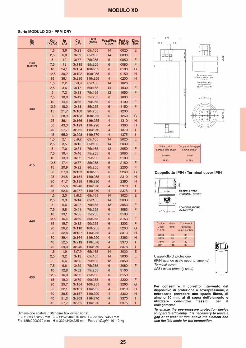
25
Codice diam. ConfezioniCode (mm) Packages
316.52 n. pz. per box
.3338 85 30
.3339 90 30
.3340 100 30
.3341 116 30
CONDENSATORECAPACITOR
CAPPELLOTTOTERMINAL COVER
Cappellotto IP54 / Terminal cover IP54
Cappellotto di protezione (IP54 quando usato opportunamente)Terminal cover (IP54 when properly used)
MODULO XD
Serie MODULO XD - PPM DRY
Per consentire il corretto intervento deldispositivo di protezione a sovrapressione, ènecessario prevedere uno spazio libero, dialmeno 30 mm, al di sopra dellʼelemento eutilizzare conduttori flessibili per ilcollegamento.To enable the overpressure protection deviceto operate efficiently, it is necessary to leave agap of at least 30 mm. above the element anduse flexible leads for the connection.
Viti e codoli Coppia di fissaggioScrews and studs Fixing torque
Screws 1,5 Nm
M 12 11 Nm
Un(V)
Qn(kVAr)
In(A)
Cn(μF)
DxH(mm) Pezzi/Pcs
x boxPart n.416.46.
Dim.Box
240(60Hz)
1,5 3,6 3x23 65x165 14 0020 E2,5 6,0 3x39 65x165 14 0030 E5 12 3x77 75x255 6 0050 F
7,5 18 3x115 85x255 6 0080 F10 24,1 3x154 100x255 6 0100 G
12,5 30,2 3x192 100x255 6 0150 H15 36,1 3x230 116x255 4 0200 H
400
1,5 2,2 3x9,9 65x165 14 1020 E2,5 3,6 3x17 65x165 14 1030 E5 7,2 3x33 75x165 12 1050 F
7,5 10,8 3x49 75x255 6 1080 F10 14,4 3x66 75x255 6 1100 F
12,5 18,0 3x83 85x255 6 1150 F15 21,7 3x100 90x255 6 1200 F20 28,9 3x133 100x255 6 1260 G25 36,1 3x166 116x255 4 1310 H30 43,3 3x199 116x290 4 1360 H40 57,7 3x265 116x370 4 1370 I45 65,0 3x298 116x370 4 1375 I
415
1,5 2,1 3x9,2 65x165 14 2020 E2,5 3,5 3x15 65x165 14 2030 E5 7,0 3x31 75x165 12 2050 F
7,5 10,4 3x46 75x255 6 2080 F10 13,9 3x62 75x255 6 2100 F
12,5 17,4 3x77 85x255 6 2150 F15 20,9 3x92 90x255 6 2200 F20 27,8 3x123 100x255 6 2260 G25 34,8 3x154 116x255 4 2310 H30 41,7 3x185 116x290 4 2360 H40 55,6 3x246 116x370 4 2370 I45 62,6 3x277 116x370 4 2375 I
440
1,5 2,0 3x8,2 65x165 14 3023 E2,5 3,3 3x14 65x165 14 3033 E5 6,6 3x27 75x165 12 3053 F
7,5 9,8 3x41 75x255 6 3083 F10 13,1 3x55 75x255 6 3103 F
12,5 16,4 3x69 85x255 6 3153 F15 19,7 3x82 90x255 6 3203 F20 26,2 3x110 100x255 6 3263 G25 32,8 3x137 116x255 4 3313 H30 39,4 3x164 116x290 4 3363 H40 52,5 3x219 116x370 4 3373 I45 59,0 3x246 116x370 4 3378 I
450
1,5 1,9 3x7,9 65x165 14 3020 E2,5 3,2 3x13 65x165 14 3030 E5 6,4 3x26 75x165 12 3050 F
7,5 9,6 3x39 75x255 6 3080 F10 12,8 3x52 75x255 6 3100 F
12,5 16,0 3x66 85x255 6 3150 F15 19,2 3x79 90x255 6 3200 F20 25,7 3x10⁴ 100x255 6 3260 G25 32,1 3x131 116x255 4 3310 H30 38,5 3x157 116x290 4 3360 H40 51,3 3x209 116x370 4 3370 I45 57,7 3x235 116x370 4 3375 I
Dimensione scatole / Standard box dimensions:E = 195x390x255 mm G = 225x340x270 mm I = 270x270x450 mmF = 185x290x270 mm H = 330x340x225 mm Peso / Weight: 10÷12 kg
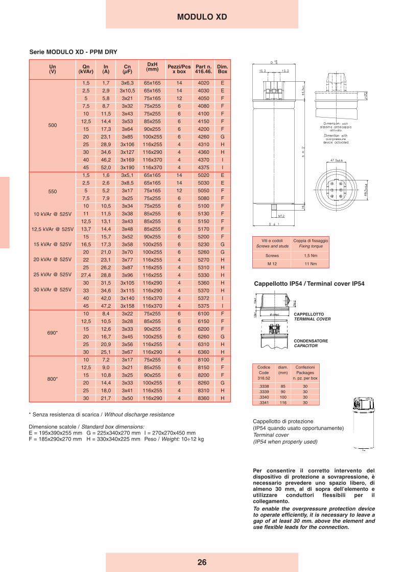
26
MODULO XD
Codice diam. ConfezioniCode (mm) Packages
316.52 n. pz. per box
.3338 85 30
.3339 90 30
.3340 100 30
.3341 116 30
CONDENSATORECAPACITOR
CAPPELLOTTOTERMINAL COVER
Cappellotto IP54 / Terminal cover IP54
Cappellotto di protezione (IP54 quando usato opportunamente)Terminal cover (IP54 when properly used)
Per consentire il corretto intervento deldispositivo di protezione a sovrapressione, ènecessario prevedere uno spazio libero, dialmeno 30 mm, al di sopra dellʼelemento eutilizzare conduttori flessibili per ilcollegamento.To enable the overpressure protection deviceto operate efficiently, it is necessary to leave agap of at least 30 mm. above the element anduse flexible leads for the connection.
Viti e codoli Coppia di fissaggioScrews and studs Fixing torque
Screws 1,5 Nm
M 12 11 Nm
Serie MODULO XD - PPM DRY
Un(V)
Qn(kVAr)
In(A)
Cn(μF)
DxH(mm) Pezzi/Pcs
x boxPart n.416.46.
Dim.Box
500
1,5 1,7 3x6,3 65x165 14 4020 E
2,5 2,9 3x10,5 65x165 14 4030 E
5 5,8 3x21 75x165 12 4050 F
7,5 8,7 3x32 75x255 6 4080 F
10 11,5 3x43 75x255 6 4100 F
12,5 14,4 3x53 85x255 6 4150 F
15 17,3 3x64 90x255 6 4200 F
20 23,1 3x85 100x255 6 4260 G
25 28,9 3x10⁶ 116x255 4 4310 H
30 34,6 3x127 116x290 4 4360 H
40 46,2 3x169 116x370 4 4370 I
45 52,0 3x190 116x370 4 4375 I
550
10 kVAr @ 525V
12,5 kVAr @ 525V
15 kVAr @ 525V
20 kVAr @ 525V
25 kVAr @ 525V
30 kVAr @ 525V
1,5 1,6 3x5,1 65x165 14 5020 E
2,5 2,6 3x8,5 65x165 14 5030 E
5 5,2 3x17 75x165 12 5050 F
7,5 7,9 3x25 75x255 6 5080 F
10 10,5 3x34 75x255 6 5100 F
11 11,5 3x38 85x255 6 5130 F
12,5 13,1 3x43 85x255 6 5150 F
13,7 14,4 3x48 85x255 6 5170 F
15 15,7 3x52 90x255 6 5200 F
16,5 17,3 3x58 100x255 6 5230 G
20 21,0 3x70 100x255 6 5260 G
22 23,1 3x77 116x255 4 5270 H
25 26,2 3x87 116x255 4 5310 H
27,4 28,8 3x96 116x255 4 5330 H
30 31,5 3x10⁵ 116x290 4 5360 H
33 34,6 3x115 116x290 4 5370 H
40 42,0 3x140 116x370 4 5372 I
45 47,2 3x158 116x370 4 5375 I
690*
10 8,4 3x22 75x255 6 6100 F
12,5 10,5 3x28 85x255 6 6150 F
15 12,6 3x33 90x255 6 6200 F
20 16,7 3x45 100x255 6 6260 G
25 20,9 3x56 116x255 4 6310 H
30 25,1 3x67 116x290 4 6360 H
800*
10 7,2 3x17 75x255 6 8100 F
12,5 9,0 3x21 85x255 6 8150 F
15 10,8 3x25 90x255 6 8200 F
20 14,4 3x33 100x255 6 8260 G
25 18,0 3x41 116x255 4 8310 H
30 21,7 3x50 116x290 4 8360 H
* Senza resistenza di scarica / Without discharge resistance
Dimensione scatole / Standard box dimensions:E = 195x390x255 mm G = 225x340x270 mm I = 270x270x450 mmF = 185x290x270 mm H = 330x340x225 mm Peso / Weight: 10÷12 kg
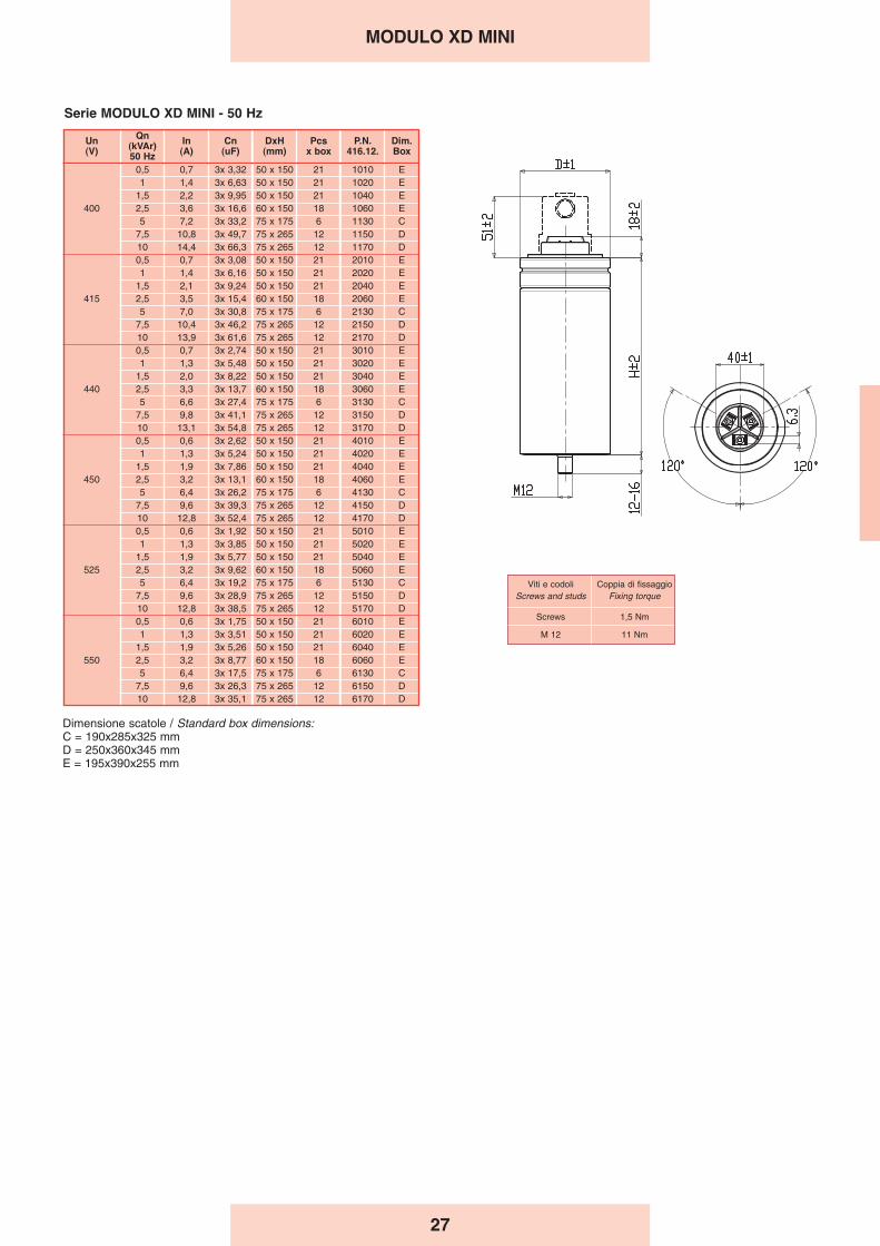
27
MODULO XD MINI
Serie MODULO XD MINI - 50 Hz
Viti e codoli Coppia di fissaggioScrews and studs Fixing torque
Screws 1,5 Nm
M 12 11 Nm
Un(V)
Qn(kVAr)50 Hz
In(A)
Cn(uF)
DxH(mm)
Pcsx box
P.N.416.12.
Dim.Box
400
0,5 0,7 3x 3,32 50 x 150 21 1010 E1 1,4 3x 6,63 50 x 150 21 1020 E
1,5 2,2 3x 9,95 50 x 150 21 1040 E2,5 3,6 3x 16,6 60 x 150 18 1060 E5 7,2 3x 33,2 75 x 175 6 1130 C
7,5 10,8 3x 49,7 75 x 265 12 1150 D10 14,4 3x 66,3 75 x 265 12 1170 D
415
0,5 0,7 3x 3,08 50 x 150 21 2010 E1 1,4 3x 6,16 50 x 150 21 2020 E
1,5 2,1 3x 9,24 50 x 150 21 2040 E2,5 3,5 3x 15,4 60 x 150 18 2060 E5 7,0 3x 30,8 75 x 175 6 2130 C
7,5 10,4 3x 46,2 75 x 265 12 2150 D10 13,9 3x 61,6 75 x 265 12 2170 D
440
0,5 0,7 3x 2,74 50 x 150 21 3010 E1 1,3 3x 5,48 50 x 150 21 3020 E
1,5 2,0 3x 8,22 50 x 150 21 3040 E2,5 3,3 3x 13,7 60 x 150 18 3060 E5 6,6 3x 27,4 75 x 175 6 3130 C
7,5 9,8 3x 41,1 75 x 265 12 3150 D10 13,1 3x 54,8 75 x 265 12 3170 D
450
0,5 0,6 3x 2,62 50 x 150 21 4010 E1 1,3 3x 5,24 50 x 150 21 4020 E
1,5 1,9 3x 7,86 50 x 150 21 4040 E2,5 3,2 3x 13,1 60 x 150 18 4060 E5 6,4 3x 26,2 75 x 175 6 4130 C
7,5 9,6 3x 39,3 75 x 265 12 4150 D10 12,8 3x 52,4 75 x 265 12 4170 D
525
0,5 0,6 3x 1,92 50 x 150 21 5010 E1 1,3 3x 3,85 50 x 150 21 5020 E
1,5 1,9 3x 5,77 50 x 150 21 5040 E2,5 3,2 3x 9,62 60 x 150 18 5060 E5 6,4 3x 19,2 75 x 175 6 5130 C
7,5 9,6 3x 28,9 75 x 265 12 5150 D10 12,8 3x 38,5 75 x 265 12 5170 D
550
0,5 0,6 3x 1,75 50 x 150 21 6010 E1 1,3 3x 3,51 50 x 150 21 6020 E
1,5 1,9 3x 5,26 50 x 150 21 6040 E2,5 3,2 3x 8,77 60 x 150 18 6060 E5 6,4 3x 17,5 75 x 175 6 6130 C
7,5 9,6 3x 26,3 75 x 265 12 6150 D10 12,8 3x 35,1 75 x 265 12 6170 D
Dimensione scatole / Standard box dimensions:C = 190x285x325 mmD = 250x360x345 mmE = 195x390x255 mm
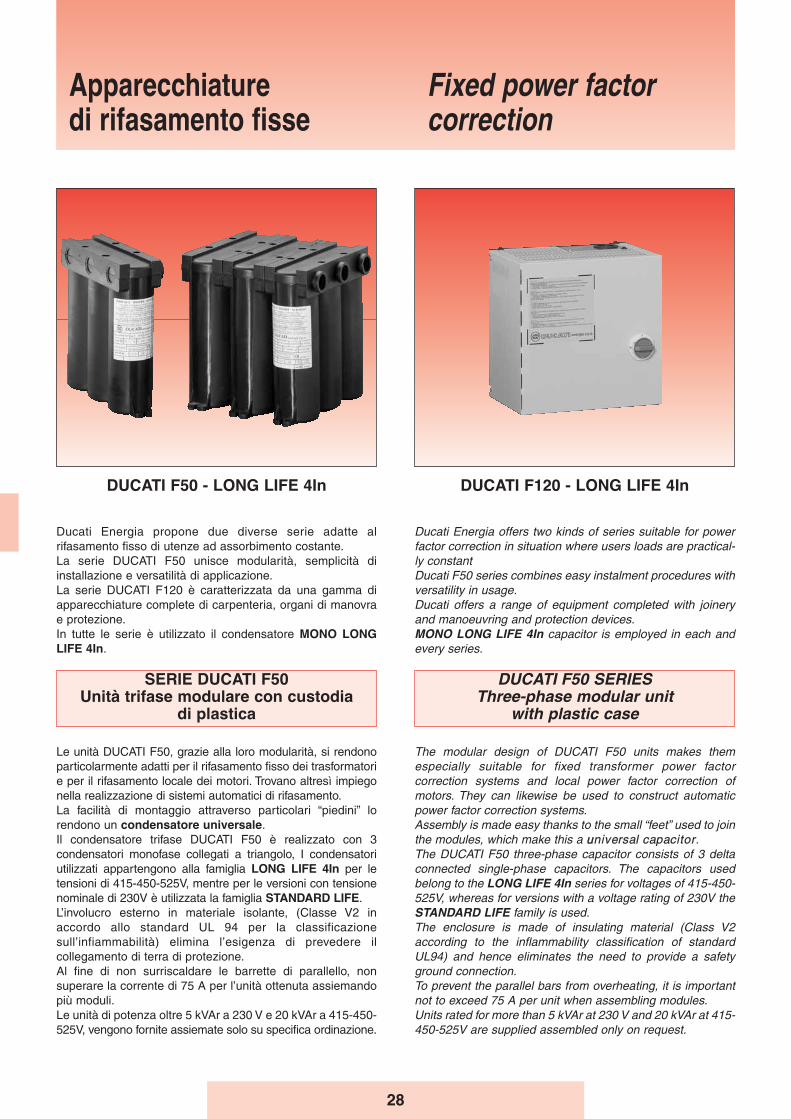
28
Ducati Energia offers two kinds of series suitable for powerfactor correction in situation where users loads are practical-ly constantDucati F50 series combines easy instalment procedures withversatility in usage.Ducati offers a range of equipment completed with joineryand manoeuvring and protection devices.MONO LONG LIFE 4In capacitor is employed in each andevery series.
DUCATI F50 SERIESThree-phase modular unit
with plastic case
The modular design of DUCATI F50 units makes themespecially suitable for fixed transformer power factorcorrection systems and local power factor correction ofmotors. They can likewise be used to construct automaticpower factor correction systems.Assembly is made easy thanks to the small “feet” used to jointhe modules, which make this a uuniversal capacitor.The DUCATI F50 three-phase capacitor consists of 3 deltaconnected single-phase capacitors. The capacitors usedbelong to the LONG LIFE 4In series for voltages of 415-450-525V, whereas for versions with a voltage rating of 230V theSTANDARD LIFE family is used.The enclosure is made of insulating material (Class V2according to the inflammability classification of standardUL94) and hence eliminates the need to provide a safetyground connection.To prevent the parallel bars from overheating, it is importantnot to exceed 75 A per unit when assembling modules.Units rated for more than 5 kVAr at 230 V and 20 kVAr at 415-450-525V are supplied assembled only on request.
Ducati Energia propone due diverse serie adatte alrifasamento fisso di utenze ad assorbimento costante.La serie DUCATI F50 unisce modularità, semplicità diinstallazione e versatilità di applicazione.La serie DUCATI F120 è caratterizzata da una gamma diapparecchiature complete di carpenteria, organi di manovrae protezione.In tutte le serie è utilizzato il condensatore MONO LONGLIFE 4In.
SERIE DUCATI F50Unità trifase modulare con custodia
di plastica
Le unità DUCATI F50, grazie alla loro modularità, si rendonoparticolarmente adatti per il rifasamento fisso dei trasformatorie per il rifasamento locale dei motori. Trovano altresì impiegonella realizzazione di sistemi automatici di rifasamento.La facilità di montaggio attraverso particolari “piedini” lorendono un condensatore universale.Il condensatore trifase DUCATI F50 è realizzato con 3condensatori monofase collegati a triangolo, I condensatoriutilizzati appartengono alla famiglia LONG LIFE 4In per letensioni di 415-450-525V, mentre per le versioni con tensionenominale di 230V è utilizzata la famiglia STANDARD LIFE.L’involucro esterno in materiale isolante, (Classe V2 inaccordo allo standard UL 94 per la classificazionesull’infiammabilità) elimina l’esigenza di prevedere ilcollegamento di terra di protezione.Al fine di non surriscaldare le barrette di parallello, nonsuperare la corrente di 75 A per l’unità ottenuta assiemandopiù moduli.Le unità di potenza oltre 5 kVAr a 230 V e 20 kVAr a 415-450-525V, vengono fornite assiemate solo su specifica ordinazione.
Apparecchiaturedi rifasamento fisse
Fixed power factor correction
DUCATI F50 - LONG LIFE 4In DUCATI F120 - LONG LIFE 4In
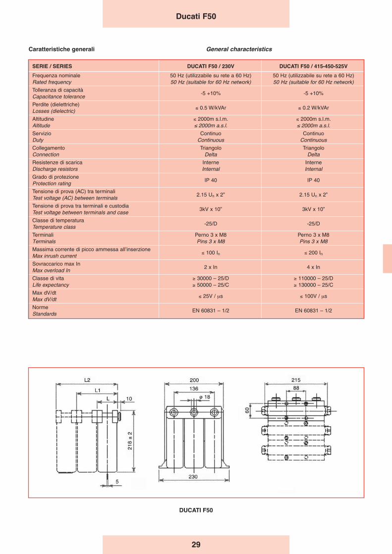
29
DUCATI F50
SERIE / SERIES DUCATI F50 / 230V DUCATI F50 / 415-450-525V
Frequenza nominale 50 Hz (utilizzabile su rete a 60 Hz) 50 Hz (utilizzabile su rete a 60 Hz)Rated frequency 50 Hz (suitable for 60 Hz network) 50 Hz (suitable for 60 Hz network)
Tolleranza di capacità-5 +10% -5 +10%
Capacitance tolerance
Perdite (dielettriche)≤ 0.5 W/kVAr ≤ 0.2 W/kVAr
Losses (dielectric)
Altitudine ≤ 2000m s.l.m. ≤ 2000m s.l.m.Altitude ≤ 2000m a.s.l. ≤ 2000m a.s.l.
Servizio Continuo ContinuoDuty Continuous Continuous
Collegamento Triangolo TriangoloConnection Delta Delta
Resistenze di scarica Interne InterneDischarge resistors Internal Internal
Grado di protezioneIP 40 IP 40
Protection rating
Tensione di prova (AC) tra terminali2.15 Un x 2” 2.15 Un x 2”
Test voltage (AC) between terminals
Tensione di prova tra terminali e custodia3kV x 10” 3kV x 10”
Test voltage between terminals and case
Classe di temperatura-25/D -25/D
Temperature class
Terminali Perno 3 x M8 Perno 3 x M8Terminals Pins 3 x M8 Pins 3 x M8
Massima corrente di picco ammessa all’inserzione≤ 100 In ≤ 200 InMax inrush current
Sovraccarico max In2 x In 4 x In
Max overload In
Classe di vita ≥ 30000 – 25/D ≥ 110000 – 25/DLife expectancy ≥ 50000 – 25/C ≥ 130000 – 25/C
Max dV/dt≤ 25V / μs ≤ 100V / μs
Max dV/dt
NormeEN 60831 – 1/2 EN 60831 – 1/2
Standards
General characteristics Caratteristiche generali
Ducati F50
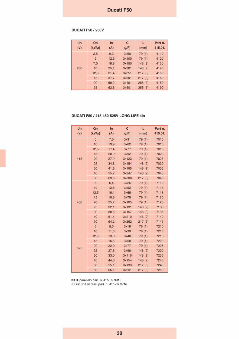
30
Un Qn In C L Part n.
(V) (kVAr) (A) (μF) (mm) 415.01.
2,5 6,3 3x50 79 (1) 4110
5 12,6 3x100 79 (1) 4120
7,5 18,8 3x150 148 (2) 4130
230 10 25,1 3x201 148 (2) 4140
12,5 31,4 3x251 217 (3) 4150
15 37,7 3x301 217 (3) 4160
20 50,2 3x401 286 (4) 4180
25 62,8 3x501 355 (5) 4190
DUCATI F50 / 230V
DUCATI F50 / 415-450-525V LONG LIFE 4In
Un Qn In C L Part n.
(V) (kVAr) (A) (μF) (mm) 415.04.
5 7,0 3x31 79 (1) 7010
10 13,9 3x62 79 (1) 7015
12,5 17,4 3x77 79 (1) 7018
15 20,9 3x92 79 (1) 7020
415 20 27,9 3x123 79 (1) 7025
25 34,8 3x154 148 (2) 7030
30 41,8 3x185 148 (2) 7035
40 55,7 3x247 148 (2) 7040
50 69,6 3x308 217 (3) 7045
5 6,4 3x26 79 (1) 7110
10 12,8 3x52 79 (1) 7115
12,5 16,1 3x66 79 (1) 7118
15 19,3 3x79 79 (1) 7120
450 20 25,7 3x10⁵ 79 (1) 7125
25 32,1 3x131 148 (2) 7130
30 38,5 3x157 148 (2) 7135
40 51,4 3x210 148 (2) 7140
50 64,2 3x262 217 (3) 7145
5 5,5 3x19 79 (1) 7210
10 11,0 3x39 79 (1) 7215
12,5 13,8 3x48 79 (1) 7218
15 16,5 3x58 79 (1) 7220
52520 22,0 3x77 79 (1) 7225
25 27,5 3x96 148 (2) 7230
30 33,0 3x116 148 (2) 7235
40 44,0 3x154 148 (2) 7240
50 55,1 3x193 217 (3) 7245
60 66,1 3x231 217 (3) 7250
Ducati F50
Kit di parallelo part. n. 415.69.9910Kit for unit parallel part. n. 415.69.9910

31
Ducati F120
SERIE DUCATI F120Unità trifase con sezionatore
e struttura metallica
Le unità DUCATI F120 sono progettate e realizzate per ilrifasamento fisso di utenze ad assorbimento costante.
Caratteristiche Generali- Tensione nominale della rete di alimentazione: 400V 50Hz
(altri valori a richiesta)- Alimentazione: trifase + PE- Corrente di cortocircuito (1s): 8÷13kA
(80kA condizionati da fusibile a monte)- Classe di temperatura: –15 +40 °C
– 0 +55 °C su richiesta- Umidità relativa: 70% max. a 20 °C- Ingresso cavi dall’alto direttamente sui morsetti del
sezionatore generale- Norme: CEI EN 61921
Condensatori 4In- Elementi monofase serie MONO - LONG LIFE collegati a
triangolo.- Tensione nominale 415-450-525V
Struttura Meccanica- La struttura di base è realizzata in lamiera di acciaio zincata
bianco dello spessore di 15/10; le piastre di fissaggio deicomponenti hanno spessore di 12/10.
- I componenti interni sono accessibili a mezzo involucrointerbloccato con il sezionatore generale.
- La struttura esterna in carpenteria di lamiera d’acciaio èverniciata con trattamento di pulitura, sgrassaggio, ciclo difosfatazione, vernice dello spessore di 50 μm a base dipolveri epossidiche colore RAL 7032.
- Nella parte inferiore e superiore sono presenti appositeferitoie per agevolare e consentire una facile ventilazionenaturale. Il grado di protezione di tali aperture è IP30.
Modalità dʼinstallazione- Per interno, a muro, in ambiente ventilato e non polveroso,
al riparo dalla luce diretta del sole.- Ingresso cavi dall’alto.
Sezionatore Generale- Sezionatore omnipolare, con blocco porta e del tipo a
velocità indipendente da quella di manovra dell’operatore.- Corrente nominale del sezionatore 1,43 volte la corrente di
esercizio a 400 V.
Collegamenti Interni- Cablaggi realizzati con cavi tipo N07VK.
Fusibili- A valle del sezionatore sono presenti una o più terne di
fusibili, posti a protezione delle batterie di condensatori.- I fusibili sono del tipo NH-00 con caratteristica GL
Dispositivi di protezione- Ogni batteria di condensatori é dotata di dispositivi di scarica
atti a ridurre la tensione residua al di sotto del 10% dellatensione nominale del condensatore in circa 30 secondi.
Collaudo 100%Su ogni apparecchiatura prodotta sono effettuate le seguentiprove e controlli:- Controllo visivo e dimensionale.- Controllo funzionamento meccanico.- Prova di tensione applicata verso massa sui circuiti di
potenza: 3kV per 1 minuto.- Controllo funzionamento elettrico a 400V.
DUCATI F120 SeriesFixed power factor
correction unit
DUCATI F120 units are designed and built for fixed powerfactor improvement in situations where user loads arepractically constant.
General Characteristics- Rated voltage of power mains: 400V 50Hz (other values on
request)- Power supply: three-phase + ground- Short circuit current (1s): 8÷13kA
(80kA fused condional)- Temperature class: –15 +40 °C
– 0 +55 °C on request- Relative humidity: 70% max at 20 °C- Cable inlet from top directly to main disconnecting switch
terminals- Standards: CEI EN 61921
Capacitors 4In- Single-phase elements series MONO - LONG LIFE in delta
connection.- Rated voltage 415-450-525V
Mechanical Structure- The basic structure is made of white galvanized steel sheet
with thickness 15/10; the component fastening plates havethickness 12/10.
- The internal components are accessible through the shellinterlocked with the main disconnecting switch.
- The outer steel structural work is painted with cleaningtreatment, degreasing, phosphating, 50 μm thickness paintwith epoxy powder colour RAL 7032.
- Special slits at the top and bottom assist natural ventilation.The protection rating of these openings is IP30.
Installation- Indoors, wall-mounted, in ventilated, non-dusty environment,
away from direct sunlight.- Cable inlet from top.
Main Disconnecting Switch- Unipolar disconnecting switch, with door lock, speed
independent of operator manoeuvring speed.- Rated current of disconnecting switch 1.43 times the 400V
operating current.
Internal Connections - Wired with N07VK type cables.
Fuses- Downstream of the disconnecting switch are one or more
triads of fuses, installed to protect the capacitor banks.- The fuses are NH-00 type with GL characteristic
Safety devices- Each capacitor bank is equipped with discharge devices for
reducing the residual voltage to less than 10% of the ratedvoltage of the capacitor in approximately 30 seconds.
100% TestingThe following tests and checks are run on every automaticdevice manufactured:- Visual and dimensional check.- Mechanical operation check.- Applied voltage test to earth on power circuits: 3kV for 1
minute.- Electrical operation check at 400V.
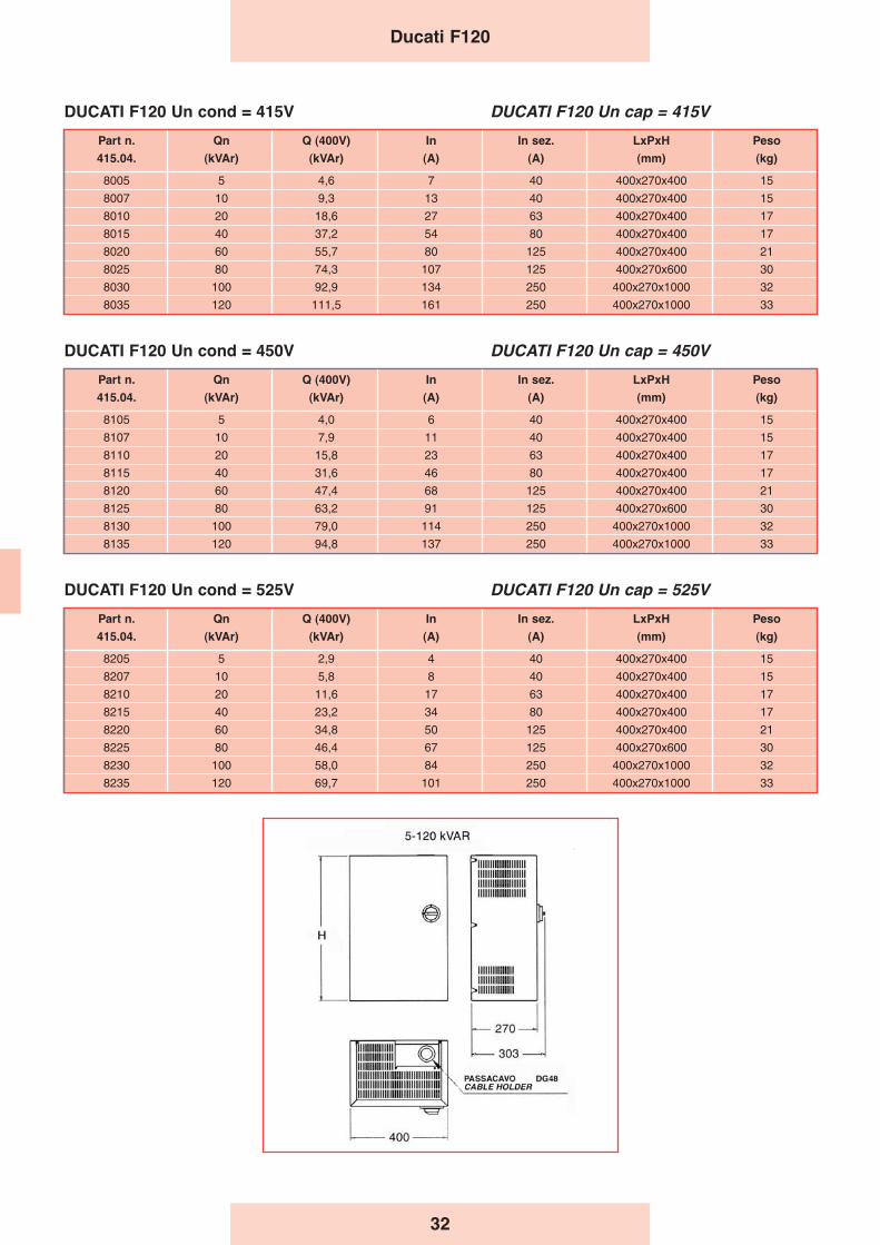
32
Ducati F120
Part n. Qn Q (400V) In In sez. LxPxH Peso
415.04. (kVAr) (kVAr) (A) (A) (mm) (kg)
8005 5 4,6 7 40 400x270x400 15
8007 10 9,3 13 40 400x270x400 15
8010 20 18,6 27 63 400x270x400 17
8015 40 37,2 54 80 400x270x400 17
8020 60 55,7 80 125 400x270x400 21
8025 80 74,3 107 125 400x270x600 30
8030 100 92,9 134 250 400x270x1000 32
8035 120 111,5 161 250 400x270x1000 33
DUCATI F120 Un cond = 415V DUCATI F120 Un cap = 415V
Part n. Qn Q (400V) In In sez. LxPxH Peso
415.04. (kVAr) (kVAr) (A) (A) (mm) (kg)
8105 5 4,0 6 40 400x270x400 15
8107 10 7,9 11 40 400x270x400 15
8110 20 15,8 23 63 400x270x400 17
8115 40 31,6 46 80 400x270x400 17
8120 60 47,4 68 125 400x270x400 21
8125 80 63,2 91 125 400x270x600 30
8130 100 79,0 114 250 400x270x1000 32
8135 120 94,8 137 250 400x270x1000 33
DUCATI F120 Un cond = 450V DUCATI F120 Un cap = 450V
Part n. Qn Q (400V) In In sez. LxPxH Peso
415.04. (kVAr) (kVAr) (A) (A) (mm) (kg)
8205 5 2,9 4 40 400x270x400 15
8207 10 5,8 8 40 400x270x400 15
8210 20 11,6 17 63 400x270x400 17
8215 40 23,2 34 80 400x270x400 17
8220 60 34,8 50 125 400x270x400 21
8225 80 46,4 67 125 400x270x600 30
8230 100 58,0 84 250 400x270x1000 32
8235 120 69,7 101 250 400x270x1000 33
DUCATI F120 Un cond = 525V DUCATI F120 Un cap = 525V

33
DUCATI ENERGIA progetta e realizza apparecchiatureautomatiche per il rifasamento industriale in bassa tensioneda 5kVAr a 1600kVAr, incentrandole sul condensatoreMONO LONG LIFE 4In.Lo staff del R&D Ducati Energia è a disposizione per lostudio di progetti ad hoc a seconda dell’esigenza del cliente.
NOTE PER L̓ INSTALLAZIONE
Come richiesto dalle norme vigenti, occorre prevedere unopportuno mezzo di protezione contro il cortocircuito ed ilsovraccarico (interruttore magnetotermico o terna difusibili) a protezione della linea di alimentazionedell’apparecchiatura di rifasamento. I mezzi di protezionedovranno essere dimensionati per correnti capacitive (circa1,3 volte la corrente nominale dell’apparecchiatura) etenendo conto della corrente di cortocircuito di breve durataprevista nel punto di installazione e sostenibile dalleapparecchiature di rifasamento.
DUCATI ENERGIA designs and realizes automaticequipment specifically for low voltage power factor correctionstarting from 5kVar to 1600 kVar, based in particular onMONO LONG LIFE 4ln capacitor.Ducati Energia R&D staff is available to study adhoc projects, depending on each customerʼs needs.
INSTALLATION NOTE
As required by the regulations in force, it is necessary toensure an appropriate protection against short-circuit andoverload (via magnetic/thermic circuit breaker or fuses) forthe line supplying the PFC equipments. The protectionmust be dimensioned for capacitive currents (approx. 1,3times the equipment’s nominal current) and taking intoaccount the short-time short-circuit current valuesexpected in the point of installation and sustainable by thePFC equipment.
Automatic power factor correction
Apparecchiaturedi rifasamentoautomatiche
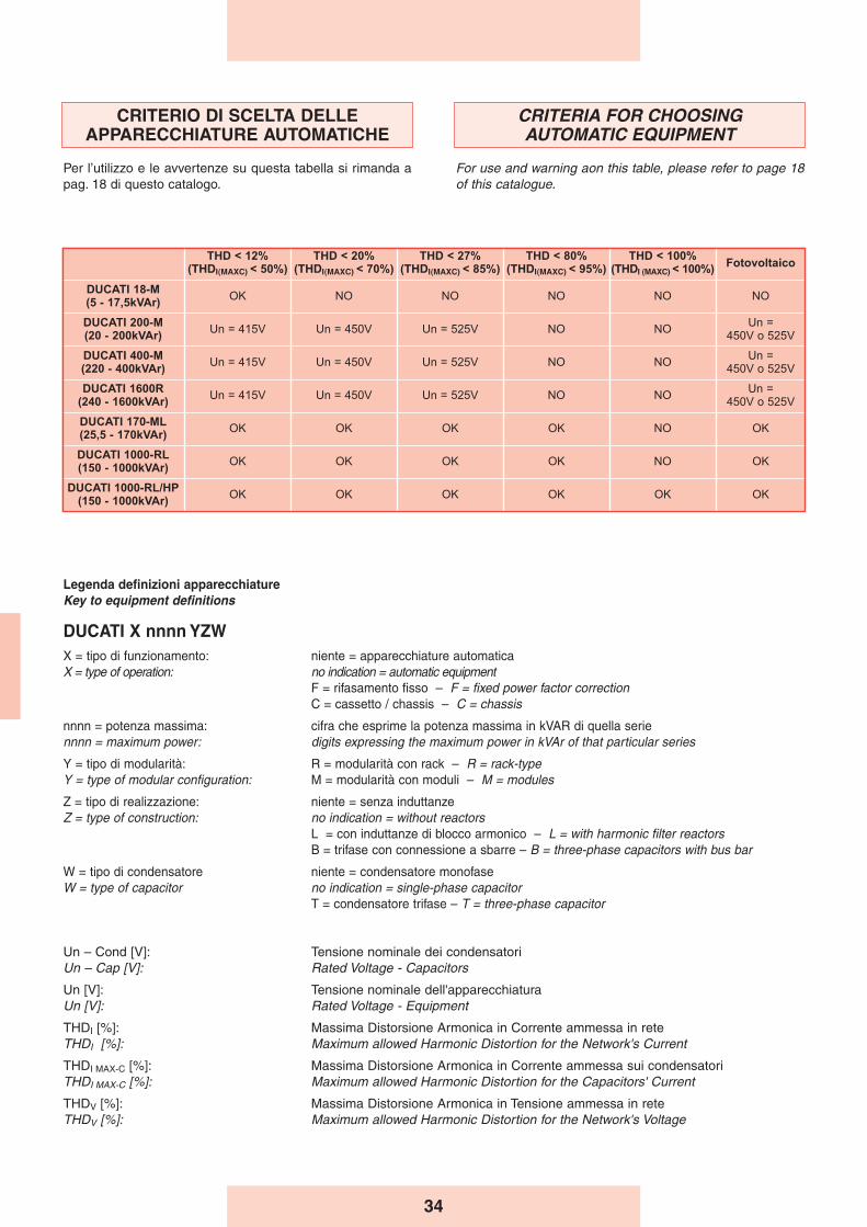
34
CRITERIA FOR CHOOSINGAUTOMATIC EQUIPMENT
For use and warning aon this table, please refer to page 18of this catalogue.
CRITERIO DI SCELTA DELLEAPPARECCHIATURE AUTOMATICHE
Per l’utilizzo e le avvertenze su questa tabella si rimanda apag. 18 di questo catalogo.
Legenda definizioni apparecchiatureKey to equipment definitions
DUCATI X nnnn YZWX = tipo di funzionamento: niente = apparecchiature automaticaX = type of operation: no indication = automatic equipment
F = rifasamento fisso – F = fixed power factor correction C = cassetto / chassis – C = chassis
nnnn = potenza massima: cifra che esprime la potenza massima in kVAR di quella seriennnn = maximum power: digits expressing the maximum power in kVAr of that particular series
Y = tipo di modularità: R = modularità con rack – R = rack-typeY = type of modular configuration: M = modularità con moduli – M = modules
Z = tipo di realizzazione: niente = senza induttanzeZ = type of construction: no indication = without reactors
L = con induttanze di blocco armonico – L = with harmonic filter reactorsB = trifase con connessione a sbarre – B = three-phase capacitors with bus bar
W = tipo di condensatore niente = condensatore monofaseW = type of capacitor no indication = single-phase capacitor
T = condensatore trifase – T = three-phase capacitor
Un – Cond [V]: Tensione nominale dei condensatoriUn – Cap [V]: Rated Voltage - Capacitors
Un [V]: Tensione nominale dell'apparecchiaturaUn [V]: Rated Voltage - Equipment
THDI [%]: Massima Distorsione Armonica in Corrente ammessa in reteTHDI [%]: Maximum allowed Harmonic Distortion for the Network's Current
THDI MAX-C [%]: Massima Distorsione Armonica in Corrente ammessa sui condensatoriTHDI MAX-C [%]: Maximum allowed Harmonic Distortion for the Capacitors' Current
THDV [%]: Massima Distorsione Armonica in Tensione ammessa in reteTHDV [%]: Maximum allowed Harmonic Distortion for the Network's Voltage
THD < 12%(THDI(MAXC) < 50%)
THD < 20%(THDI(MAXC) < 70%)
THD < 27%(THDI(MAXC) < 85%)
THD < 80%(THDI(MAXC) < 95%)
THD < 100%(THDI (MAXC) < 100%)
Fotovoltaico
DUCATI 18-M(5 - 17,5kVAr)
OK NO NO NO NO NO
DUCATI 200-M(20 - 200kVAr)
Un = 415V Un = 450V Un = 525V NO NOUn =
450V o 525V
DUCATI 400-M(220 - 400kVAr)
Un = 415V Un = 450V Un = 525V NO NOUn =
450V o 525V
DUCATI 1600R(240 - 1600kVAr)
Un = 415V Un = 450V Un = 525V NO NOUn =
450V o 525V
DUCATI 170-ML(25,5 - 170kVAr)
OK OK OK OK NO OK
DUCATI 1000-RL(150 - 1000kVAr)
OK OK OK OK NO OK
DUCATI 1000-RL/HP(150 - 1000kVAr)
OK OK OK OK OK OK

35
General Characteristics- Power range: 2.5÷50 kVAr (230V) - 5÷17.5 kVAR (400V).- Mains voltage (working voltage): standard 230-400 V (other
voltages on request).- Rated frequency: 50 Hz (60 Hz on request).- Short circuit current (1s): 0.5÷8kA
(80kA fused condional)- Altitude: ≤ 2000 m a.s.l.- Relative humidity: 70% max. at 20 °C- Duty: continuous.- Ambient temperature class: -5 + 40 °C
(on request + 55 °C)- Standards: CEI EN 61921
Electrical Characteristics- Power supply line: Three-phase + ground
(for 400V mains version only)- Relay current input signal: from CT on line .../5A- Relay voltage input signal: picked up internally.
Capacitors- Single-phase elements series FLOPPY CAP - STANDARD
LIFE in delta connection.- Rated voltage 230-415V.
Mechanical Structure- The basic structure is made of white galvanized steel sheet
with thickness 15/10; the component fastening plates havethickness 12/10.
- The internal components are accessible through the shellinterlocked with the main disconnecting switch.
DUCATI 18-M Seriesautomatic power factor correction unit
Caratteristiche Generali- Gamma di potenza: 2.5÷50 kVAr (230V) -
5÷17.5 kVAR (400V).- Tensione di rete (impiego): standard 230-400 V (altre
tensioni su richiesta).- Frequenza nominale: 50 Hz (60 Hz a richiesta).- Corrente di cortocircuito (1s): 0,5÷8kA
(80kA condizionati da fusibile a monte)- Altitudine: ≤ 2000 m s.l.m.- Umidità relativa: 70% max. a 20 °C- Servizio: continuo.- Classe di temperatura ambiente: -5 + 40 °C
(su richiesta + 55 °C)- Norme: CEI EN 61921
Caratteristiche Elettriche- Linea di alimentazione: Trifase + PE
(solo per la versione per rete a 400V)- Segnale Amperometrico: da TA in linea .../5A- Segnale Voltmetrico: prelevato internamente.
Condensatori- Elementi monofase serie FLOPPY CAP - STANDARD
LIFE collegati a triangolo.- Tensione nominale 230-415V.
Struttura Meccanica- La struttura di base è realizzata in lamiera di acciaio zincata
bianco dello spessore di 15/10; le piastre di fissaggio deicomponenti hanno spessore di 12/10.
- I componenti interni sono accessibili a mezzo involucrointerbloccato con il sezionatore generale.
Serie DUCATI 18-Munità rifasamentoautomatico
DUCATI 18-M - STANDARD LIFE DUCATI 18-M - STANDARD LIFE IP54
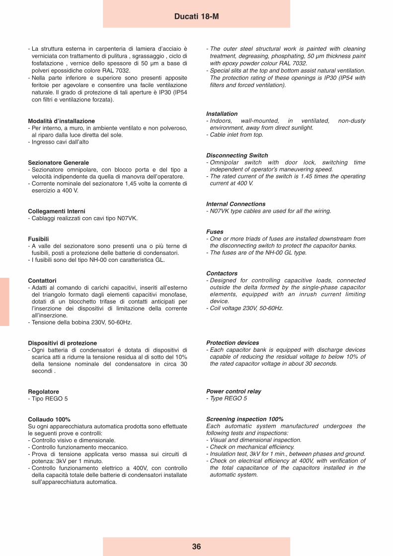
36
- La struttura esterna in carpenteria di lamiera d’acciaio èverniciata con trattamento di pulitura , sgrassaggio , ciclo difosfatazione , vernice dello spessore di 50 μm a base dipolveri epossidiche colore RAL 7032.
- Nella parte inferiore e superiore sono presenti appositeferitoie per agevolare e consentire una facile ventilazionenaturale. Il grado di protezione di tali aperture è IP30 (IP54con filtri e ventilazione forzata).
Modalità dʼinstallazione- Per interno, a muro, in ambiente ventilato e non polveroso,
al riparo dalla luce diretta del sole.- Ingresso cavi dall’alto
Sezionatore Generale- Sezionatore omnipolare, con blocco porta e del tipo a
velocità indipendente da quella di manovra dell’operatore.- Corrente nominale del sezionatore 1,45 volte la corrente di
esercizio a 400 V.
Collegamenti Interni- Cablaggi realizzati con cavi tipo N07VK.
Fusibili- A valle del sezionatore sono presenti una o più terne di
fusibili, posti a protezione delle batterie di condensatori.- I fusibili sono del tipo NH-00 con caratteristica GL.
Contattori- Adatti al comando di carichi capacitivi, inseriti all’esterno
del triangolo formato dagli elementi capacitivi monofase,dotati di un blocchetto trifase di contatti anticipati perl’inserzione dei dispositivi di limitazione della correnteall’inserzione.
- Tensione della bobina 230V, 50-60Hz.
Dispositivi di protezione- Ogni batteria di condensatori é dotata di dispositivi di
scarica atti a ridurre la tensione residua al di sotto del 10%della tensione nominale del condensatore in circa 30secondi .
Regolatore- Tipo REGO 5
Collaudo 100%Su ogni apparecchiatura automatica prodotta sono effettuatele seguenti prove e controlli:- Controllo visivo e dimensionale.- Controllo funzionamento meccanico.- Prova di tensione applicata verso massa sui circuiti di
potenza: 3kV per 1 minuto.- Controllo funzionamento elettrico a 400V, con controllo
della capacità totale delle batterie di condensatori installatesull’apparecchiatura automatica.
- The outer steel structural work is painted with cleaningtreatment, degreasing, phosphating, 50 μm thickness paintwith epoxy powder colour RAL 7032.
- Special slits at the top and bottom assist natural ventilation.The protection rating of these openings is IP30 (IP54 withfilters and forced ventilation).
Installation- Indoors, wall-mounted, in ventilated, non-dusty
environment, away from direct sunlight.- Cable inlet from top.
Disconnecting Switch- Omnipolar switch with door lock, switching time
independent of operator’s maneuvering speed.- The rated current of the switch is 1.45 times the operating
current at 400 V.
Internal Connections- N07VK type cables are used for all the wiring.
Fuses- One or more triads of fuses are installed downstream from
the disconnecting switch to protect the capacitor banks.- The fuses are of the NH-00 GL type.
Contactors- Designed for controlling capacitive loads, connected
outside the delta formed by the single-phase capacitorelements, equipped with an inrush current limitingdevice.
- Coil voltage 230V, 50-60Hz.
Protection devices- Each capacitor bank is equipped with discharge devices
capable of reducing the residual voltage to below 10% ofthe rated capacitor voltage in about 30 seconds.
Power control relay- Type REGO 5
Screening inspection 100%Each automatic system manufactured undergoes thefollowing tests and inspections:- Visual and dimensional inspection.- Check on mechanical efficiency.- Insulation test, 3kV for 1 min., between phases and ground.- Check on electrical efficiency at 400V, with verification of
the total capacitance of the capacitors installed in theautomatic system.
Ducati 18-M
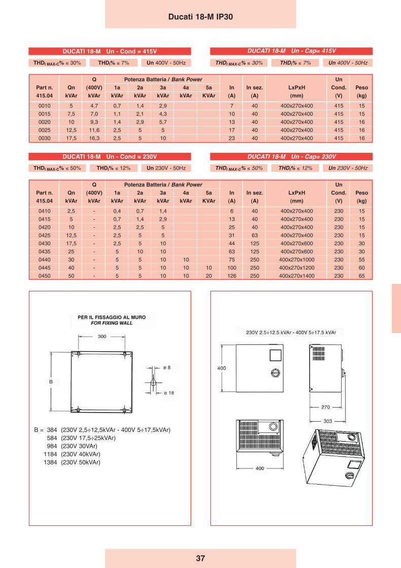
37
Q Potenza Batteria / Bank Power Un
Part n. Qn (400V) 1a 2a 3a 4a 5a In In sez. LxPxH Cond. Peso
415.04 kVAr kVAr kVAr kVAr kVAr kVAr KVAr (A) (A) (mm) (V) (kg)
0410 2,5 - 0,4 0,7 1,4 6 40 400x270x400 230 15
0415 5 - 0,7 1,4 2,9 13 40 400x270x400 230 15
0420 10 - 2,5 2,5 5 25 40 400x270x400 230 15
0425 12,5 - 2,5 5 5 31 63 400x270x400 230 15
0430 17,5 - 2,5 5 10 44 125 400x270x600 230 30
0435 25 - 5 10 10 63 125 400x270x600 230 30
0440 30 - 5 5 10 10 75 250 400x270x1000 230 55
0445 40 - 5 5 10 10 10 100 250 400x270x1200 230 60
0450 50 - 5 5 10 10 20 126 250 400x270x1400 230 65
Ducati 18-M IP30
Q Potenza Batteria / Bank Power Un
Part n. Qn (400V) 1a 2a 3a 4a 5a In In sez. LxPxH Cond. Peso
415.04 kVAr kVAr kVAr kVAr kVAr kVAr KVAr (A) (A) (mm) (V) (kg)
0010 5 4,7 0,7 1,4 2,9 7 40 400x270x400 415 15
0015 7,5 7,0 1,1 2,1 4,3 10 40 400x270x400 415 15
0020 10 9,3 1,4 2,9 5,7 13 40 400x270x400 415 16
0025 12,5 11,6 2,5 5 5 17 40 400x270x400 415 16
0030 17,5 16,3 2,5 5 10 23 40 400x270x400 415 16
B = 384 (230V 2,5÷12,5kVAr - 400V 5÷17,5kVAr)584 (230V 17,5÷25kVAr)984 (230V 30VAr)
1184 (230V 40kVAr)1384 (230V 50kVAr)
DUCATI 18-M Un - Cond = 230V
THDI MAX-C% ≤ 50% THDI% ≤ 12% Un 230V - 50Hz
DUCATI 18-M Un - Cap= 230V
THDI MAX-C% ≤ 50% THDI% ≤ 12% Un 230V - 50Hz
THDI MAX-C% ≤ 30% THDI% ≤ 7% Un 400V - 50Hz
DUCATI 18-M Un - Cond = 415V
THDI MAX-C% ≤ 30% THDI% ≤ 7% Un 400V - 50Hz
DUCATI 18-M Un - Cap= 415V
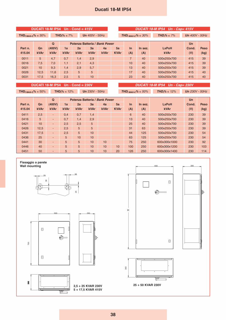
38
Ducati 18-M IP54
Q Potenza Batteria / Bank Power Un
Part n. Qn (400V) 1a 2a 3a 4a 5a In In sez. LxPxH Cond. Peso
415.04 kVAr kVAr kVAr kVAr kVAr kVAr KVAr (A) (A) kVAr (V) (kg)
0011 5 4,7 0,7 1,4 2,9 7 40 500x250x700 415 39
0016 7,5 7,0 1,1 2,1 4,3 10 40 500x250x700 415 39
0021 10 9,3 1,4 2,9 5,7 13 40 500x250x700 415 39
0026 12,5 11,6 2,5 5 5 17 40 500x250x700 415 40
0031 17,5 16,3 2,5 5 10 23 40 500x250x700 415 40
Q Potenza Batteria / Bank Power Un
Part n. Qn (400V) 1a 2a 3a 4a 5a In In sez. LxPxH Cond. Peso
415.04 kVAr kVAr kVAr kVAr kVAr kVAr KVAr (A) (A) kVAr (V) (kg)
0411 2,5 - 0,4 0,7 1,4 6 40 500x250x700 230 39
0416 5 - 0,7 1,4 2,9 13 40 500x250x700 230 39
0421 10 - 2,5 2,5 5 25 40 500x250x700 230 39
0426 12,5 - 2,5 5 5 31 63 500x250x700 230 39
0431 17,5 - 2,5 5 10 44 125 500x250x700 230 54
0436 25 - 5 10 10 63 125 500x250x700 230 54
0441 30 - 5 5 10 10 75 250 600x300x1000 230 92
0446 40 - 5 5 10 10 10 100 250 600x300x1200 230 103
0451 50 - 5 5 10 10 20 126 250 600x300x1400 230 114
Fissaggio a pareteWall mounting
H
25 ÷ 50 KVAR 230V2,5 ÷ 25 KVAR 230V5 ÷ 17,5 KVAR 415V
DUCATI 18-M IP54 Un - Cap= 415V
THDI MAX-C% ≤ 30% THDI% ≤ 7% Un 400V - 50Hz
DUCATI 18-M IP54 Un - Cap= 230V
THDI MAX-C% ≤ 50% THDI% ≤ 12% Un 230V - 50Hz
DUCATI 18-M IP54 Un - Cond = 415V
THDI MAX-C% ≤ 30% THDI% ≤ 7% Un 400V - 50Hz
DUCATI 18-M IP54 Un - Cond = 230V
THDI MAX-C% ≤ 50% THDI% ≤ 12% Un 230V - 50Hz
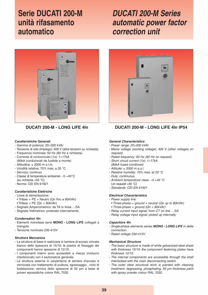
39
General Characteristics- Power range: 20÷200 kVAr - Mains voltage (working voltage): 400 V (other voltages on
request).- Rated frequency: 50 Hz (60 Hz on request).- Short circuit current (1s): 1÷17kA
(80kA fused condional)- Altitude: ≤ 2000 m a.s.l.- Relative humidity: 70% max. at 20 °C- Duty: continuous.- Ambient temperature class: –5 +40 °C
(on request +55 °C)- Standards: CEI EN 61921
Electrical Characteristics- Power supply line:
• Three-phase + ground + neutral (Qn up to 80kVAr)• Three-phase + ground (Qn > 80kVAr)
- Relay current input signal: from CT on line .../5A- Relay voltage input signal: picked up internally.
Capacitors 4In- Single-phase elements series MONO - LONG LIFE in delta
connection.- Rated voltage 230-415V
Mechanical Structure- The basic structure is made of white galvanized steel sheet
with thickness 15/10; the component fastening plates havethickness 12/10.
- The internal components are accessible through the shellinterlocked with the main disconnecting switch.
- The outer steel structural work is painted with cleaningtreatment, degreasing, phosphating, 50 μm thickness paintwith epoxy powder colour RAL 7032.
Caratteristiche Generali- Gamma di potenza: 20÷200 kVAr- Tensione di rete (impiego): 400 V (altre tensioni su richiesta).- Frequenza nominale: 50 Hz (60 Hz a richiesta).- Corrente di cortocircuito (1s): 1÷17kA
(80kA condizionati da fusibile a monte)- Altitudine: ≤ 2000 m s.l.m.- Umidità relativa: 70% max. a 20 °C- Servizio: continuo.- Classe di temperatura ambiente: –5 +40°C
(su richiesta +55 °C)- Norme: CEI EN 61921
Caratteristiche Elettriche- Linea di alimentazione:
• Trifase + PE + Neutro (Qn fino a 80kVAr)• Trifase + PE (Qn > 80kVAr)
- Segnale Amperometrico: da TA in linea .../5A- Segnale Voltmetrico: prelevato internamente.
Condensatori 4In- Elementi monofase serie MONO - LONG LIFE collegati a
triangolo.- Tensione nominale 230-415V
Struttura Meccanica- La struttura di base è realizzata in lamiera di acciaio zincata
bianco dello spessore di 15/10; le piastre di fissaggio deicomponenti hanno spessore di 12/10.
- I componenti interni sono accessibili a mezzo involucrointerbloccato con il sezionatore generale.
- La struttura esterna in carpenteria di lamiera d’acciaio èverniciata con trattamento di pulitura, sgrassaggio , ciclo difosfatazione, vernice dello spessore di 50 μm a base dipolveri epossidiche colore RAL 7032.
Serie DUCATI 200-Munità rifasamentoautomatico
DUCATI 200-M Seriesautomatic power factorcorrection unit
DUCATI 200-M - LONG LIFE 4In DUCATI 200-M - LONG LIFE 4In IP54
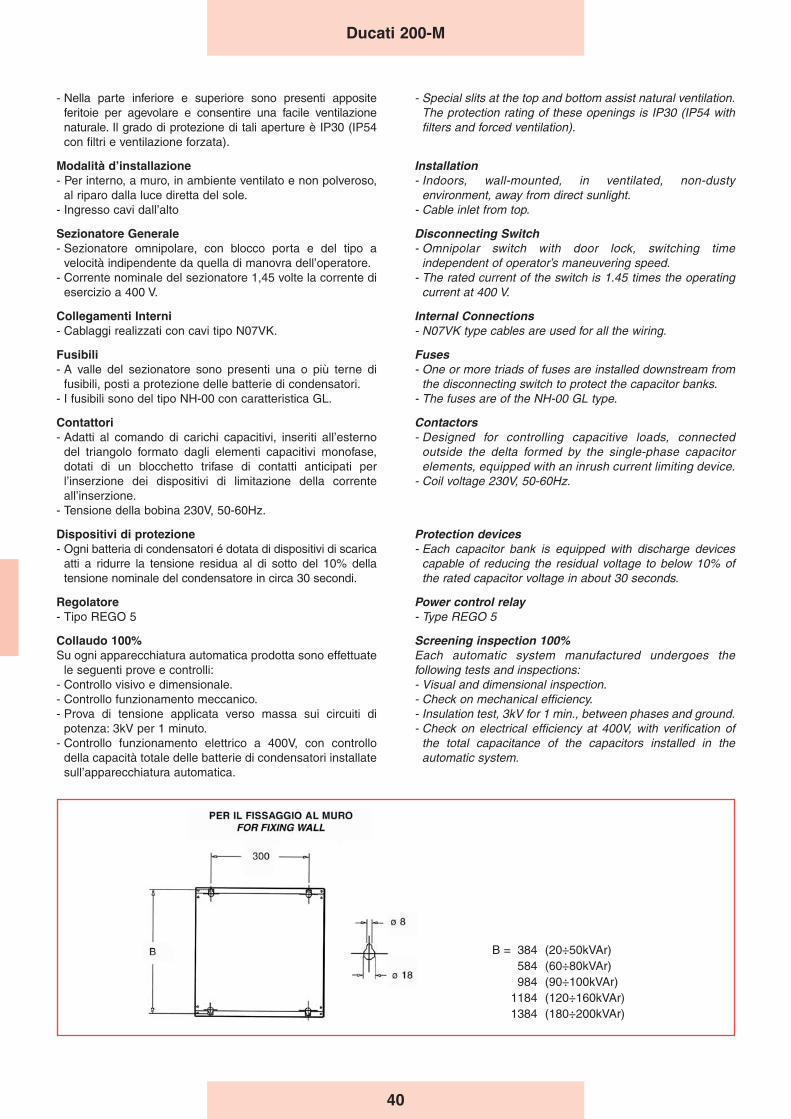
40
- Special slits at the top and bottom assist natural ventilation.The protection rating of these openings is IP30 (IP54 withfilters and forced ventilation).
Installation- Indoors, wall-mounted, in ventilated, non-dusty
environment, away from direct sunlight.- Cable inlet from top.
Disconnecting Switch- Omnipolar switch with door lock, switching time
independent of operator’s maneuvering speed.- The rated current of the switch is 1.45 times the operating
current at 400 V.
Internal Connections- N07VK type cables are used for all the wiring.
Fuses- One or more triads of fuses are installed downstream from
the disconnecting switch to protect the capacitor banks.- The fuses are of the NH-00 GL type.
Contactors- Designed for controlling capacitive loads, connected
outside the delta formed by the single-phase capacitorelements, equipped with an inrush current limiting device.
- Coil voltage 230V, 50-60Hz.
Protection devices- Each capacitor bank is equipped with discharge devices
capable of reducing the residual voltage to below 10% ofthe rated capacitor voltage in about 30 seconds.
Power control relay- Type REGO 5
Screening inspection 100%Each automatic system manufactured undergoes thefollowing tests and inspections:- Visual and dimensional inspection.- Check on mechanical efficiency.- Insulation test, 3kV for 1 min., between phases and ground.- Check on electrical efficiency at 400V, with verification of
the total capacitance of the capacitors installed in theautomatic system.
Ducati 200-M
B = 384 (20÷50kVAr)584 (60÷80kVAr)984 (90÷100kVAr)
1184 (120÷160kVAr)1384 (180÷200kVAr)
- Nella parte inferiore e superiore sono presenti appositeferitoie per agevolare e consentire una facile ventilazionenaturale. Il grado di protezione di tali aperture è IP30 (IP54con filtri e ventilazione forzata).
Modalità dʼinstallazione- Per interno, a muro, in ambiente ventilato e non polveroso,
al riparo dalla luce diretta del sole.- Ingresso cavi dall’alto
Sezionatore Generale- Sezionatore omnipolare, con blocco porta e del tipo a
velocità indipendente da quella di manovra dell’operatore.- Corrente nominale del sezionatore 1,45 volte la corrente di
esercizio a 400 V.
Collegamenti Interni- Cablaggi realizzati con cavi tipo N07VK.
Fusibili- A valle del sezionatore sono presenti una o più terne di
fusibili, posti a protezione delle batterie di condensatori.- I fusibili sono del tipo NH-00 con caratteristica GL.
Contattori- Adatti al comando di carichi capacitivi, inseriti all’esterno
del triangolo formato dagli elementi capacitivi monofase,dotati di un blocchetto trifase di contatti anticipati perl’inserzione dei dispositivi di limitazione della correnteall’inserzione.
- Tensione della bobina 230V, 50-60Hz.
Dispositivi di protezione- Ogni batteria di condensatori é dotata di dispositivi di scarica
atti a ridurre la tensione residua al di sotto del 10% dellatensione nominale del condensatore in circa 30 secondi.
Regolatore- Tipo REGO 5
Collaudo 100%Su ogni apparecchiatura automatica prodotta sono effettuate
le seguenti prove e controlli:- Controllo visivo e dimensionale.- Controllo funzionamento meccanico.- Prova di tensione applicata verso massa sui circuiti di
potenza: 3kV per 1 minuto.- Controllo funzionamento elettrico a 400V, con controllo
della capacità totale delle batterie di condensatori installatesull’apparecchiatura automatica.
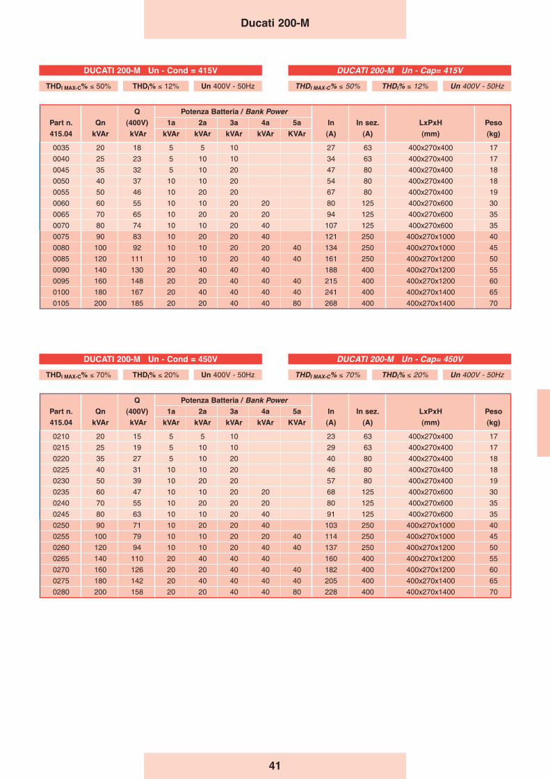
41
Q Potenza Batteria / Bank PowerPart n. Qn (400V) 1a 2a 3a 4a 5a In In sez. LxPxH Peso
415.04 kVAr kVAr kVAr kVAr kVAr kVAr KVAr (A) (A) (mm) (kg)
0035 20 18 5 5 10 27 63 400x270x400 17
0040 25 23 5 10 10 34 63 400x270x400 17
0045 35 32 5 10 20 47 80 400x270x400 18
0050 40 37 10 10 20 54 80 400x270x400 18
0055 50 46 10 20 20 67 80 400x270x400 19
0060 60 55 10 10 20 20 80 125 400x270x600 30
0065 70 65 10 20 20 20 94 125 400x270x600 35
0070 80 74 10 10 20 40 107 125 400x270x600 35
0075 90 83 10 20 20 40 121 250 400x270x1000 40
0080 100 92 10 10 20 20 40 134 250 400x270x1000 45
0085 120 111 10 10 20 40 40 161 250 400x270x1200 50
0090 140 130 20 40 40 40 188 400 400x270x1200 55
0095 160 148 20 20 40 40 40 215 400 400x270x1200 60
0100 180 167 20 40 40 40 40 241 400 400x270x1400 65
0105 200 185 20 20 40 40 80 268 400 400x270x1400 70
Q Potenza Batteria / Bank PowerPart n. Qn (400V) 1a 2a 3a 4a 5a In In sez. LxPxH Peso
415.04 kVAr kVAr kVAr kVAr kVAr kVAr KVAr (A) (A) (mm) (kg)
0210 20 15 5 5 10 23 63 400x270x400 17
0215 25 19 5 10 10 29 63 400x270x400 17
0220 35 27 5 10 20 40 80 400x270x400 18
0225 40 31 10 10 20 46 80 400x270x400 18
0230 50 39 10 20 20 57 80 400x270x400 19
0235 60 47 10 10 20 20 68 125 400x270x600 30
0240 70 55 10 20 20 20 80 125 400x270x600 35
0245 80 63 10 10 20 40 91 125 400x270x600 35
0250 90 71 10 20 20 40 103 250 400x270x1000 40
0255 100 79 10 10 20 20 40 114 250 400x270x1000 45
0260 120 94 10 10 20 40 40 137 250 400x270x1200 50
0265 140 110 20 40 40 40 160 400 400x270x1200 55
0270 160 126 20 20 40 40 40 182 400 400x270x1200 60
0275 180 142 20 40 40 40 40 205 400 400x270x1400 65
0280 200 158 20 20 40 40 80 228 400 400x270x1400 70
Ducati 200-M
DUCATI 200-M Un - Cap= 415V
THDI MAX-C% ≤ 50% THDI% ≤ 12% Un 400V - 50Hz
DUCATI 200-M Un - Cap= 450V
THDI MAX-C% ≤ 70% THDI% ≤ 20% Un 400V - 50Hz
DUCATI 200-M Un - Cond = 415V
THDI MAX-C% ≤ 50% THDI% ≤ 12% Un 400V - 50Hz
DUCATI 200-M Un - Cond = 450V
THDI MAX-C% ≤ 70% THDI% ≤ 20% Un 400V - 50Hz
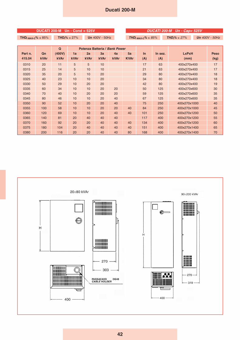
42
Ducati 200-M
Q Potenza Batteria / Bank PowerPart n. Qn (400V) 1a 2a 3a 4a 5a In In sez. LxPxH Peso
415.04 kVAr kVAr kVAr kVAr kVAr kVAr KVAr (A) (A) (mm) (kg)
0310 20 11 5 5 10 17 63 400x270x400 17
0315 25 14 5 10 10 21 63 400x270x400 17
0320 35 20 5 10 20 29 80 400x270x400 18
0325 40 23 10 10 20 34 80 400x270x400 18
0330 50 29 10 20 20 42 80 400x270x400 19
0335 60 34 10 10 20 20 50 125 400x270x600 30
0340 70 40 10 20 20 20 59 125 400x270x600 35
0345 80 46 10 10 20 40 67 125 400x270x600 35
0350 90 52 10 20 20 40 75 250 400x270x1000 40
0355 100 58 10 10 20 20 40 84 250 400x270x1000 45
0360 120 69 10 10 20 40 40 101 250 400x270x1200 50
0365 140 81 20 40 40 40 117 400 400x270x1200 55
0370 160 92 20 20 40 40 40 134 400 400x270x1200 60
0375 180 104 20 40 40 40 40 151 400 400x270x1400 65
0380 200 116 20 20 40 40 80 168 400 400x270x1400 70
DUCATI 200-M Un - Cap= 525V
THDI MAX-C% ≤ 85% THDI% ≤ 27% Un 400V - 50Hz
DUCATI 200-M Un - Cond = 525V
THDI MAX-C% ≤ 85% THDI% ≤ 27% Un 400V - 50Hz
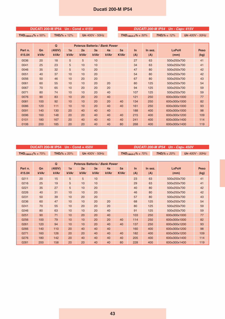
43
Ducati 200-M IP54
Q Potenza Batteria / Bank PowerPart n. Qn (400V) 1a 2a 3a 4a 5a In In sez. LxPxH Peso
415.04 kVAr kVAr kVAr kVAr kVAr kVAr KVAr (A) (A) (mm) (kg)
0211 20 15 5 5 10 23 63 500x250x700 41
0216 25 19 5 10 10 29 63 500x250x700 41
0221 35 27 5 10 20 40 80 500x250x700 42
0226 40 31 10 10 20 46 80 500x250x700 42
0231 50 39 10 20 20 57 80 500x250x700 43
0236 60 47 10 10 20 20 68 125 500x250x700 54
0241 70 55 10 20 20 20 80 125 500x250x700 59
0246 80 63 10 10 20 40 91 125 500x250x700 59
0251 90 71 10 20 20 40 103 250 600x300x1000 77
0256 100 79 10 10 20 20 40 114 250 600x300x1000 82
0261 120 94 10 10 20 40 40 137 250 600x300x1200 93
0266 140 110 20 40 40 40 160 400 600x300x1200 98
0271 160 126 20 20 40 40 40 182 400 600x300x1200 109
0276 180 142 20 40 40 40 40 205 400 600x300x1400 114
0281 200 158 20 20 40 40 80 228 400 600x300x1400 119
Q Potenza Batteria / Bank PowerPart n. Qn (400V) 1a 2a 3a 4a 5a In In sez. LxPxH Peso
415.04 kVAr kVAr kVAr kVAr kVAr kVAr KVAr (A) (A) (mm) (kg)
0036 20 18 5 5 10 27 63 500x250x700 41
0041 25 23 5 10 10 34 63 500x250x700 41
0046 35 32 5 10 20 47 80 500x250x700 42
0051 40 37 10 10 20 54 80 500x250x700 42
0056 50 46 10 20 20 67 80 500x250x700 43
0061 60 55 10 10 20 20 80 125 500x250x700 54
0067 70 65 10 20 20 20 94 125 500x250x700 59
0071 80 74 10 10 20 40 107 125 500x250x700 59
0076 90 83 10 20 20 40 121 250 600x300x1000 77
0081 100 92 10 10 20 20 40 134 250 600x300x1000 82
0086 120 111 10 10 20 40 40 161 250 600x300x1000 93
0091 140 130 20 40 40 40 188 400 600x300x1000 98
0096 160 148 20 20 40 40 40 215 400 600x300x1200 109
0101 180 167 20 40 40 40 40 241 400 600x300x1400 114
0106 200 185 20 20 40 40 80 268 400 600x300x1400 119
DUCATI 200-M IP54 Un - Cap= 415V
THDI MAX-C% ≤ 50% THDI% ≤ 12% Un 400V - 50Hz
DUCATI 200-M IP54 Un - Cap= 450V
THDI MAX-C% ≤ 70% THDI% ≤ 20% Un 400V - 50Hz
DUCATI 200-M IP54 Un - Cond = 415V
THDI MAX-C% ≤ 50% THDI% ≤ 12% Un 400V - 50Hz
DUCATI 200-M IP54 Un - Cond = 450V
THDI MAX-C% ≤ 70% THDI% ≤ 20% Un 400V - 50Hz

44
Ducati 200-M IP54
Q Potenza Batteria / Bank PowerPart n. Qn (400V) 1a 2a 3a 4a 5a In In sez. LxPxH Peso
415.04 kVAr kVAr kVAr kVAr kVAr kVAr KVAr (A) (A) (mm) (kg)
0311 20 11 5 5 10 17 63 500x250x700 41
0316 25 14 5 10 10 21 63 500x250x700 41
0321 35 20 5 10 20 29 80 500x250x700 42
0326 40 23 10 10 20 34 80 500x250x700 42
0331 50 29 10 20 20 42 80 500x250x700 43
0336 60 34 10 10 20 20 50 125 500x250x700 54
0341 70 40 10 20 20 20 59 125 500x250x700 59
0346 80 46 10 10 20 40 67 125 500x250x700 59
0351 90 52 10 20 20 40 75 250 600x300x1000 77
0356 100 58 10 10 20 20 40 84 250 600x300x1000 82
0361 120 69 10 10 20 40 40 101 250 600x300x1200 93
0366 140 81 20 40 40 40 117 400 600x300x1200 98
0371 160 92 20 20 40 40 40 134 400 600x300x1200 109
0376 180 104 20 40 40 40 40 151 400 600x300x1400 114
0381 200 116 20 20 40 40 80 168 400 600x300x1400 119
H
90 ÷ 200 KVAR20 ÷ 80 KVAR
Fissaggio a pareteWall mounting
H
90 ÷ 200 KVAR20 ÷ 80 KVAR
DUCATI 200-M IP54 Un - Cap= 525V
THDI MAX-C% ≤ 85% THDI% ≤ 27% Un 400V - 50Hz
DUCATI 200-M IP54 Un - Cond = 525V
THDI MAX-C% ≤ 85% THDI% ≤ 27% Un 400V - 50Hz
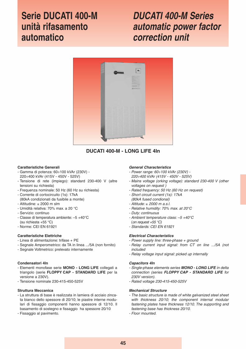
45
General Characteristics- Power range: 60÷100 kVAr (230V) -
220÷400 kVAr (415V - 450V - 525V)- Mains voltage (orking voltage): standard 230-400 V (other
voltages on request )- Rated frequency: 50 Hz (60 Hz on request)- Short circuit current (1s): 17kA
(80kA fused condional)- Altitude: ≤ 2000 m a.s.l.- Relative humidity: 70% max. at 20°C- Duty: continuous- Ambient temperature class: –5 +40°C
(on request +55 °C)- Standards: CEI EN 61921
Electrical Characteristics- Power supply line: three-phase + ground- Relay current input signal: from CT on line .../5A (not
included- Relay voltage input signal: picked up internally
Capacitors 4In- Single-phase elements series MONO - LONG LIFE in delta
connection (series FLOPPY CAP - STANDARD LIFE for230V version).
- Rated voltage 230-415-450-525V
Mechanical Structure- The basic structure is made of white galvanized steel sheet
with thickness 20/10; the component internal modularfastening plates have thickness 12/10. The supporting andfastening base has thickness 20/10.
- Floor mounted.
Caratteristiche Generali- Gamma di potenza: 60÷100 kVAr (230V) -
220÷400 kVAr (415V - 450V - 525V)- Tensione di rete (impiego): standard 230-400 V (altre
tensioni su richiesta)- Frequenza nominale: 50 Hz (60 Hz su richiesta)- Corrente di cortocircuito (1s): 17kA
(80kA condizionati da fusibile a monte)- Altitudine: ≤ 2000 m slm- Umidità relativa: 70% max. a 20 °C- Servizio: continuo- Classe di temperatura ambiente: –5 +40°C
(su richiesta +55 °C)- Norme: CEI EN 61921
Caratteristiche Elettriche- Linea di alimentazione: trifase + PE- Segnale Amperometrico: da TA in linea .../5A (non fornito)- Segnale Voltmetrico: prelevato internamente
Condensatori 4In- Elementi monofase serie MONO - LONG LIFE collegati a
triangolo (serie FLOPPY CAP - STANDARD LIFE per laversione a 230V).
- Tensione nominale 230-415-450-525V
Struttura Meccanica- La struttura di base è realizzata in lamiera di acciaio zinca-
ta bianco dello spessore di 20/10; le piastre interne modu-lari di fissaggio componenti hanno spessore di 12/10. Ilbasamento di sostegno e fissaggio ha spessore 20/10
- Fissaggio al pavimento.
Serie DUCATI 400-Munità rifasamentoautomatico
DUCATI 400-M Seriesautomatic power factorcorrection unit
DUCATI 400-M - LONG LIFE 4In
46
- La struttura esterna in carpenteria di lamiera d’acciaio èverniciata con trattamento di pulitura, sgrassaggio, ciclo difosfatazione, vernice dello spessore di 50 μm a base dipolveri epossidiche colore RAL 7032.
- Interno accessibile tramite portella interbloccata con ilsezionatore generale.
- Ventilazione forzata ottenuta tramite ventola (300m3 ora),posizionata nella parte sulla parte superiore della struttura
- Ingresso cavi dall’alto direttamente sui morsetti delsezionatore
- Grado di protezione è IP30 (IP40 su richiesta).
Modalità dʼinstallazione- Per interno, a pavimento, in ambiente ventilato e non polve-
roso, al riparo dalla luce diretta del sole.- Ingresso cavi dall’alto direttamente sui morsetti dei sezio-
natori
Sezionatore Generale- Sezionatore tripolare, con blocco porta e del tipo a velocità
indipendente da quella di manovra dell’operatore.- Corrente nominale del sezionatore 1,45 volte la corrente di
esercizio a 400 V.
Collegamenti Interni- Sistema di distribuzione interno realizzato con cavo tipo
N07V-K
Fusibili- A valle del sezionatore sono presenti più terne di fusibili,
posti a protezione delle batterie di condensatori.- I fusibili sono del tipo NH-00 con caratteristica GL.
Contattori- Adatti al comando di carichi capacitivi, inseriti all’esterno
del triangolo formato dagli elementi capacitivi monofase,dotati di un blocchetto trifase di contatti anticipati perl’inserzione dei dispositivi di limitazione della correnteall’inserzione.
- Tensione della bobina 230V, 50-60Hz.
Dispositivi di protezione- Ogni batteria di condensatori é dotata di dispositivi di
scarica atti a ridurre la tensione residua al di sotto del 10%della tensione nominale del condensatore in circa 30secondi .
Regolatore- Tipo REGO 5
Collaudo 100%Su ogni apparecchiatura automatica prodotta sono effettuate
le seguenti prove e controlli:- Controllo visivo e dimensionale.- Controllo funzionamento meccanico.- Prova di tensione applicata verso massa sui circuiti di
potenza: 3kV per 1 minuto.- Controllo funzionamento elettrico a 400V, con controllo
della capacità totale delle batterie di condensatori installatesull’apparecchiatura automatica.
- Enclosure made of sheet steel subjected to a cleaning anddegreasing treatment and phosphatizing cycle, 50 μm-thickcoat of epoxy powder paint. Color RAL 7032.
- Internal components accessible through a door interlockedwith the main disconnecting switch.
- Forced ventilation by means of a fan (300 m3/h) positionedon the top part of the structure
- Top cable entry with direct connection to switch terminals.- Protection rating is IP30 (IP40 on request).
Installation- Indoors, on the floor, in a well-ventilated, non-dusty room,
away from direct sunlight.- Cable inlet from top directly to main disconnecting switch
terminals
Disconnecting Switch- Three-pole switche with door lock, switching time
independent of operator’s maneuvering speed.- The rated current of the switch is 1.45 times the operating
current at 400 V.
Internal Connections- Internal distribution system wired with N07V-K type cables.
Fuses- One or more triads of fuses are installed downstream from
the disconnecting switch to protect the capacitor banks.- The fuses are of the NH-00 GL type.
Contactors- Designed for controlling capacitive loads, connected
outside the delta formed by the single-phase capacitorelements, equipped with an inrush current limiting device.
- Coil voltage 230V, 50-60Hz.
Protection devices- Each capacitor bank is equipped with discharge devices
capable of reducing the residual voltage to below 10% ofthe rated capacitor voltage in about 30 seconds.
Power control relay- Type REGO 5
Screening inspection 100%Each automatic system manufactured undergoes thefollowing tests and inspections:- Visual and dimensional inspection.- Check on mechanical efficiency.- Insulation test, 3kV for 1 min., between phases and ground.- Check on electrical efficiency at 400V, with verification of
the total capacitance of the capacitors installed in theautomatic system.
Ducati 400-M

47
Q Potenza Batteria / Bank PowerPart n. Qn (400V) 1a 2a 3a 4a 5a In In sez. LxPxH Peso
415.04 kVAr kVAr kVAr kVAr kVAr kVAr KVAr (A) (A) (mm) (kg)
0510N 220 204 20 40 40 40 80 295 630 800x400x1470 115
0515N 240 223 20 20 40 80 80 322 630 800x400x1470 120
0520N 260 241 20 40 40 80 80 349 630 800x400x1470 125
0525N 280 260 40 40 40 80 80 375 630 800x400x1470 130
0527N 300 278 20 40 80 80 80 402 630 800x400x1470 135
0530N 320 297 40 40 80 80 80 429 800 800x400x1470 140
0535N 360 334 40 80 80 80 80 483 800 800x400x1470 145
0540N 400 371 80 80 80 80 80 536 800 800x400x1470 150
Q Potenza Batteria / Bank PowerPart n. Qn (400V) 1a 2a 3a 4a 5a In In sez. LxPxH Peso
415.04 kVAr kVAr kVAr kVAr kVAr kVAr KVAr (A) (A) (mm) (kg)
0610N 220 173 20 40 40 40 80 251 630 800x400x1470 115
0615N 240 189 20 20 40 80 80 274 630 800x400x1470 120
0620N 260 205 20 40 40 80 80 297 630 800x400x1470 125
0625N 280 221 40 40 40 80 80 319 630 800x400x1470 130
0627N 300 237 20 40 80 80 80 342 630 800x400x1470 135
0630N 320 252 40 40 80 80 80 365 800 800x400x1470 140
0635N 360 284 40 80 80 80 80 411 800 800x400x1470 145
0640N 400 316 80 80 80 80 80 456 800 800x400x1470 150
Q Potenza Batteria / Bank PowerPart n. Qn (400V) 1a 2a 3a 4a 5a In In sez. LxPxH Peso
415.04 kVAr kVAr kVAr kVAr kVAr kVAr KVAr (A) (A) (mm) (kg)
0710N 220 127 20 40 40 40 80 184 630 800x400x1470 115
0715N 240 139 20 20 40 80 80 201 630 800x400x1470 120
0720N 260 150 20 40 40 80 80 218 630 800x400x1470 125
0725N 280 162 40 40 40 80 80 235 630 800x400x1470 130
0727N 300 174 20 40 80 80 80 251 630 800x400x1470 135
0730N 320 185 40 40 80 80 80 268 800 800x400x1470 140
0735N 360 209 40 80 80 80 80 302 800 800x400x1470 145
0740N 400 232 80 80 80 80 80 335 800 800x400x1470 150
Ducati 400-M
DUCATI 400-M Un - Cap= 415V
THDI MAX-C% ≤ 50% THDI% ≤ 12% Un 400V - 50Hz
DUCATI 400-M Un - Cap= 450V
THDI MAX-C% ≤ 70% THDI% ≤ 20% Un 400V - 50Hz
DUCATI 400-M Un - Cap= 525V
THDI MAX-C% ≤ 85% THDI% ≤ 27% Un 400V - 50Hz
DUCATI 400-M Un - Cond = 415V
THDI MAX-C% ≤ 50% THDI% ≤ 12% Un 400V - 50Hz
DUCATI 400-M Un - Cond = 450V
THDI MAX-C% ≤ 70% THDI% ≤ 20% Un 400V - 50Hz
DUCATI 400-M Un - Cond = 525V
THDI MAX-C% ≤ 85% THDI% ≤ 27% Un 400V - 50Hz
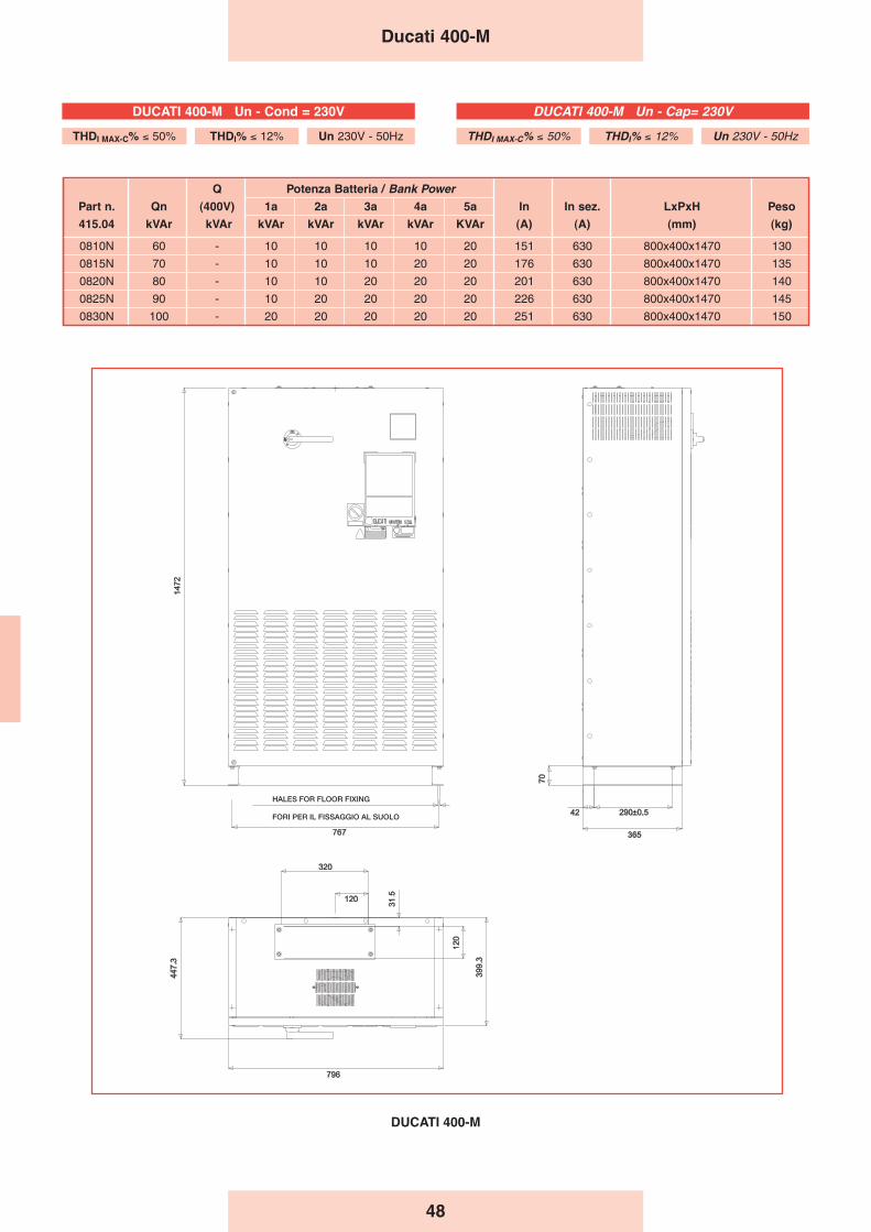
48
Q Potenza Batteria / Bank PowerPart n. Qn (400V) 1a 2a 3a 4a 5a In In sez. LxPxH Peso
415.04 kVAr kVAr kVAr kVAr kVAr kVAr KVAr (A) (A) (mm) (kg)
0810N 60 - 10 10 10 10 20 151 630 800x400x1470 130
0815N 70 - 10 10 10 20 20 176 630 800x400x1470 135
0820N 80 - 10 10 20 20 20 201 630 800x400x1470 140
0825N 90 - 10 20 20 20 20 226 630 800x400x1470 145
0830N 100 - 20 20 20 20 20 251 630 800x400x1470 150
Ducati 400-M
DUCATI 400-M
FORI PER IL FISSAGGIO AL SUOLO
HALES FOR FLOOR FIXING
DUCATI 400-M Un - Cap= 230V
THDI MAX-C% ≤ 50% THDI% ≤ 12% Un 230V - 50Hz
DUCATI 400-M Un - Cond = 230V
THDI MAX-C% ≤ 50% THDI% ≤ 12% Un 230V - 50Hz
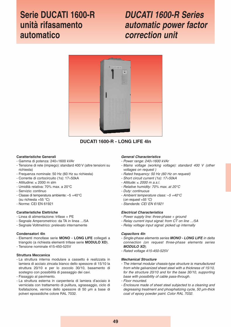
49
General Characteristics- Power range: 240÷1600 kVAr - Mains voltage (working voltage): standard 400 V (other
voltages on request )- Rated frequency: 50 Hz (60 Hz on request)- Short circuit current (1s): 17÷50kA- Altitude: ≤ 2000 m a.s.l.- Relative humidity: 70% max. at 20°C- Duty: continuous- Ambient temperature class: –5 +40°C
(on request +55 °C)- Standards: CEI EN 61921
Electrical Characteristics- Power supply line: three-phase + ground- Relay current input signal: from CT on line .../5A- Relay voltage input signal: picked up internally
Capacitors 4In- Single-phase elements series MONO - LONG LIFE in delta
connection (on request three-phase elements seriesMODULO XD).
- Rated voltage 415-450-525V
Mechanical Structure- The internal modular chassis-type structure is manufactured
from white galvanized sheet steel with a thickness of 15/10,for the structure 20/10 and for the base 30/10, supportingbase with possibility of cable pass-through.
- Floor mounted.- Enclosure made of sheet steel subjected to a cleaning and
degreasing treatment and phosphatizing cycle, 50 μm-thickcoat of epoxy powder paint. Color RAL 7032.
Caratteristiche Generali- Gamma di potenza: 240÷1600 kVAr- Tensione di rete (impiego): standard 400 V (altre tensioni su
richiesta)- Frequenza nominale: 50 Hz (60 Hz su richiesta)- Corrente di cortocircuito (1s): 17÷50kA- Altitudine: ≤ 2000 m slm- Umidità relativa: 70% max. a 20°C- Servizio: continuo- Classe di temperatura ambiente: –5 +40°C
(su richiesta +55 °C)- Norme: CEI EN 61921
Caratteristiche Elettriche- Linea di alimentazione: trifase + PE- Segnale Amperometrico: da TA in linea .../5A- Segnale Voltmetrico: prelevato internamente
Condensatori 4In- Elementi monofase serie MONO - LONG LIFE collegati a
triangolo (a richiesta elementi trifase serie MODULO XD).- Tensione nominale 415-450-525V
Struttura Meccanica- La struttura interna modulare a cassetto è realizzata in
lamiera di acciaio zincata bianco dello spessore di 15/10 lastruttura 20/10 e per lo zoccolo 30/10, basamento disostegno con possibilità di passaggio dei cavi.
- Fissaggio al pavimento.- La struttura esterna in carpenteria di lamiera d’acciaio è
verniciata con trattamento di pulitura, sgrassaggio, ciclo difosfatazione, vernice dello spessore di 50 μm a base dipolveri epossidiche colore RAL 7032.
Serie DUCATI 1600-Runità rifasamentoautomatico
DUCATI 1600-R Seriesautomatic power factorcorrection unit
DUCATI 1600-R - LONG LIFE 4In
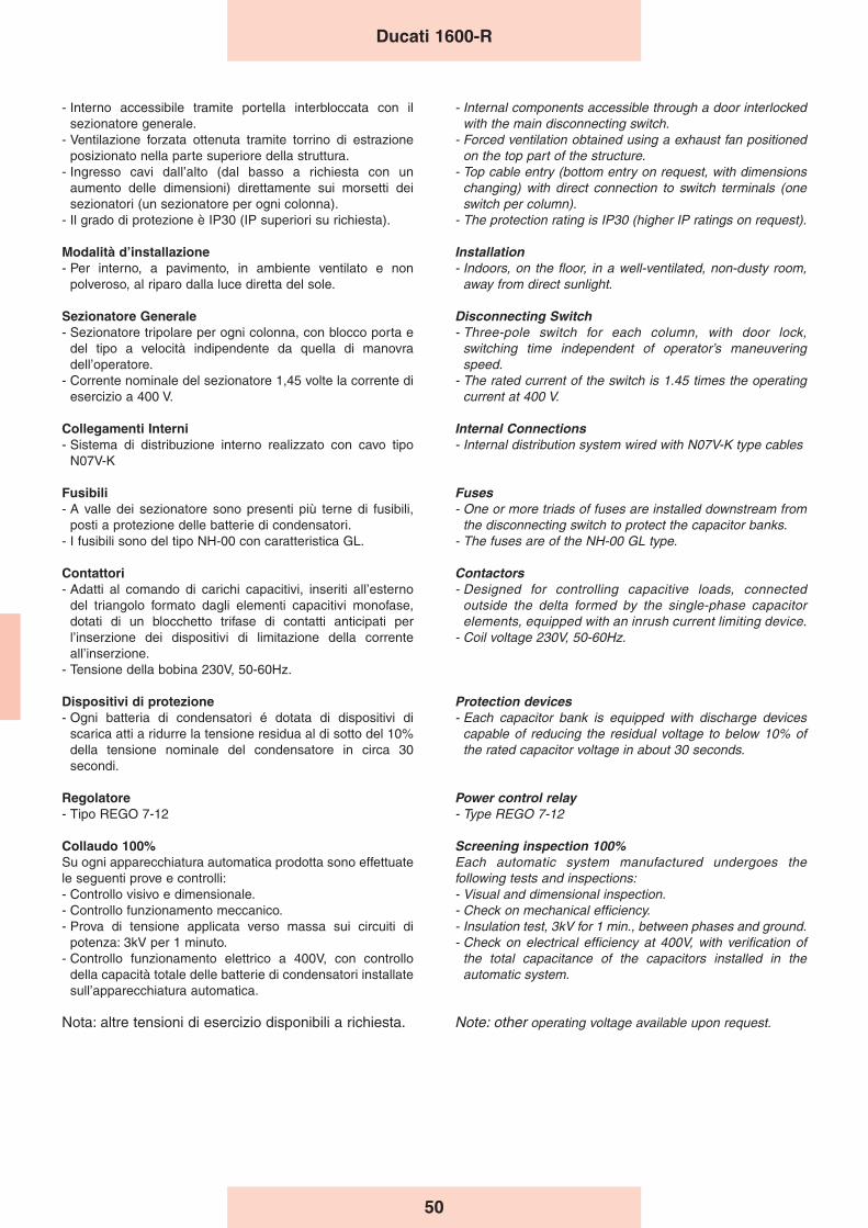
50
- Interno accessibile tramite portella interbloccata con ilsezionatore generale.
- Ventilazione forzata ottenuta tramite torrino di estrazioneposizionato nella parte superiore della struttura.
- Ingresso cavi dall’alto (dal basso a richiesta con unaumento delle dimensioni) direttamente sui morsetti deisezionatori (un sezionatore per ogni colonna).
- Il grado di protezione è IP30 (IP superiori su richiesta).
Modalità dʼinstallazione- Per interno, a pavimento, in ambiente ventilato e non
polveroso, al riparo dalla luce diretta del sole.
Sezionatore Generale- Sezionatore tripolare per ogni colonna, con blocco porta e
del tipo a velocità indipendente da quella di manovradell’operatore.
- Corrente nominale del sezionatore 1,45 volte la corrente diesercizio a 400 V.
Collegamenti Interni- Sistema di distribuzione interno realizzato con cavo tipo
N07V-K
Fusibili- A valle dei sezionatore sono presenti più terne di fusibili,
posti a protezione delle batterie di condensatori.- I fusibili sono del tipo NH-00 con caratteristica GL.
Contattori- Adatti al comando di carichi capacitivi, inseriti all’esterno
del triangolo formato dagli elementi capacitivi monofase,dotati di un blocchetto trifase di contatti anticipati perl’inserzione dei dispositivi di limitazione della correnteall’inserzione.
- Tensione della bobina 230V, 50-60Hz.
Dispositivi di protezione- Ogni batteria di condensatori é dotata di dispositivi di
scarica atti a ridurre la tensione residua al di sotto del 10%della tensione nominale del condensatore in circa 30secondi.
Regolatore- Tipo REGO 7-12
Collaudo 100%Su ogni apparecchiatura automatica prodotta sono effettuatele seguenti prove e controlli:- Controllo visivo e dimensionale.- Controllo funzionamento meccanico.- Prova di tensione applicata verso massa sui circuiti di
potenza: 3kV per 1 minuto.- Controllo funzionamento elettrico a 400V, con controllo
della capacità totale delle batterie di condensatori installatesull’apparecchiatura automatica.
Nota: altre tensioni di esercizio disponibili a richiesta.
- Internal components accessible through a door interlockedwith the main disconnecting switch.
- Forced ventilation obtained using a exhaust fan positionedon the top part of the structure.
- Top cable entry (bottom entry on request, with dimensionschanging) with direct connection to switch terminals (oneswitch per column).
- The protection rating is IP30 (higher IP ratings on request).
Installation- Indoors, on the floor, in a well-ventilated, non-dusty room,
away from direct sunlight.
Disconnecting Switch- Three-pole switch for each column, with door lock,
switching time independent of operator’s maneuveringspeed.
- The rated current of the switch is 1.45 times the operatingcurrent at 400 V.
Internal Connections- Internal distribution system wired with N07V-K type cables
Fuses- One or more triads of fuses are installed downstream from
the disconnecting switch to protect the capacitor banks.- The fuses are of the NH-00 GL type.
Contactors- Designed for controlling capacitive loads, connected
outside the delta formed by the single-phase capacitorelements, equipped with an inrush current limiting device.
- Coil voltage 230V, 50-60Hz.
Protection devices- Each capacitor bank is equipped with discharge devices
capable of reducing the residual voltage to below 10% ofthe rated capacitor voltage in about 30 seconds.
Power control relay- Type REGO 7-12
Screening inspection 100%Each automatic system manufactured undergoes thefollowing tests and inspections:- Visual and dimensional inspection.- Check on mechanical efficiency.- Insulation test, 3kV for 1 min., between phases and ground.- Check on electrical efficiency at 400V, with verification of
the total capacitance of the capacitors installed in theautomatic system.
Note: other operating voltage available upon request.
Ducati 1600-R

51
240 223 40 40 40 40 40 40 322 630 1010 800x600x1600 265 1010B 800x600x1600 265
280 260 40 40 40 40 40 40 40 375 630 1012 800x600x1600 270 1012B 800x600x1600 270
320 297 40 40 40 40 40 40 80 429 630 1015 800x600x1600 275 1015B 800x600x1600 275
360 334 40 40 40 40 40 80 80 483 1000 1017 800x600x1600 285 1017B 800x600x2100 295
400 371 40 40 40 40 80 80 80 536 1000 1020 800x600x1600 290 1020B 800x600x2100 298
440 408 40 40 40 80 80 80 80 590 1000 1022 800x600x1600 295 1022B 800x600x2100 300
480 445 40 40 80 80 80 80 80 644 1000 1025 800x600x1600 300 1025B 800x600x2100 305
520 483 40 40 40 80 80 80 80 80 697 1250 1027 800x600x2100 310 1027B 800x600x2100 310
560 520 40 40 80 80 80 80 80 80 751 1250 1030 800x600x2100 315 1030B 800x600x2100 315
600 557 40 40 40 80 80 80 80 80 80 805 1250 1032 800x600x2100 320 1032B 800x600x2100 320
640 594 40 40 80 80 80 80 80 80 80 858 1250 1035 800x600x2100 325 1035B 800x600x2100 325
680 631 40 40 40 80 80 80 80 80 80 80 912 1600 1037 800x600x2100 335 1037B 1600x600x2100 580
720 668 40 40 80 80 80 80 80 80 80 80 965 1600 1040 800x600x2100 345 1040B 1600x600x2100 582
800 743 40 40 80 80 80 80 80 80 80 80 80 1073 1600 1045 800x600x2100 350 1045B 1600x600x2100 585
880 817 40 40 80 80 80 80 80 80 80 80 80 80 1180 1000+1000 1050 1600x600x2100 580 1050B 1600x600x2100 588
960 891 80 80 80 80 80 80 80 80 80 80 80 80 1287 1000+1000 1055 1600x600x2100 590 1055B 1600x600x2100 590
1040 966 80 80 80 80 80 80 80 80 80 80 80 160 1395 1000+1250 1060 1600x600x2100 605 1060B 1600x600x2100 605
1120 1040 80 80 80 80 80 80 80 80 80 80 160 160 1502 1000+1250 1065 1600x600x2100 615 1065B 1600x600x2100 615
1200 1114 80 80 80 80 80 80 80 80 80 160 160 160 1609 1250+1250 1070 1600x600x2100 630 1070B 1600x600x2100 630
1280 1189 80 80 80 80 80 80 80 80 160 160 160 160 1716 1250+1250 1075 1600x600x2100 635 1075B 1600x600x2100 635
1360 1263 80 80 80 80 80 80 80 160 160 160 160 160 1824 1250+1600 1080 1600x600x2100 650 1080B 2400x600x2100 850
1440 1337 80 80 80 80 80 80 160 160 160 160 160 160 1931 1250+1600 1085 1600x600x2100 665 1085B 2400x600x2100 855
1520 1412 80 80 80 80 80 160 160 160 160 160 160 160 2038 1600+1600 1090 1600x600x2100 680 1090B 2400x600x2100 860
1600 1486 80 80 80 80 160 160 160 160 160 160 160 160 2145 1600+1600 1095 1600x600x2100 700 1095B 2400x600x2100 865
Ingresso cavi dal bassoBottom cable entry
PesoWeight
(kg)
Qn
kVAr
Q
(400)
kVAr
Potenza Batteria kVArBank Power kVAr
1 2 3 4 5 6 7 8 9 10 11 12
In
(A)
In sez.
(A) Part n.
415.04.
Ingresso cavi dallʼaltoTop cable entry
LxPxH (mm)Part n.
415.04.LxPxH (mm)
PesoWeight
(kg)
Ducati 1600-R
Nota: IP54 a richiesta (stesse dimensioni della tabella sopra riportata)Note: IP54 on demand (same dimensions of the above table)
DUCATI 1600-R Un - Cap= 415V
THDI MAX-C% ≤ 50% THDI% ≤ 12% Un 400V - 50Hz
DUCATI 1600-R Un - Cond = 415V
THDI MAX-C% ≤ 50% THDI% ≤ 12% Un 400V - 50Hz
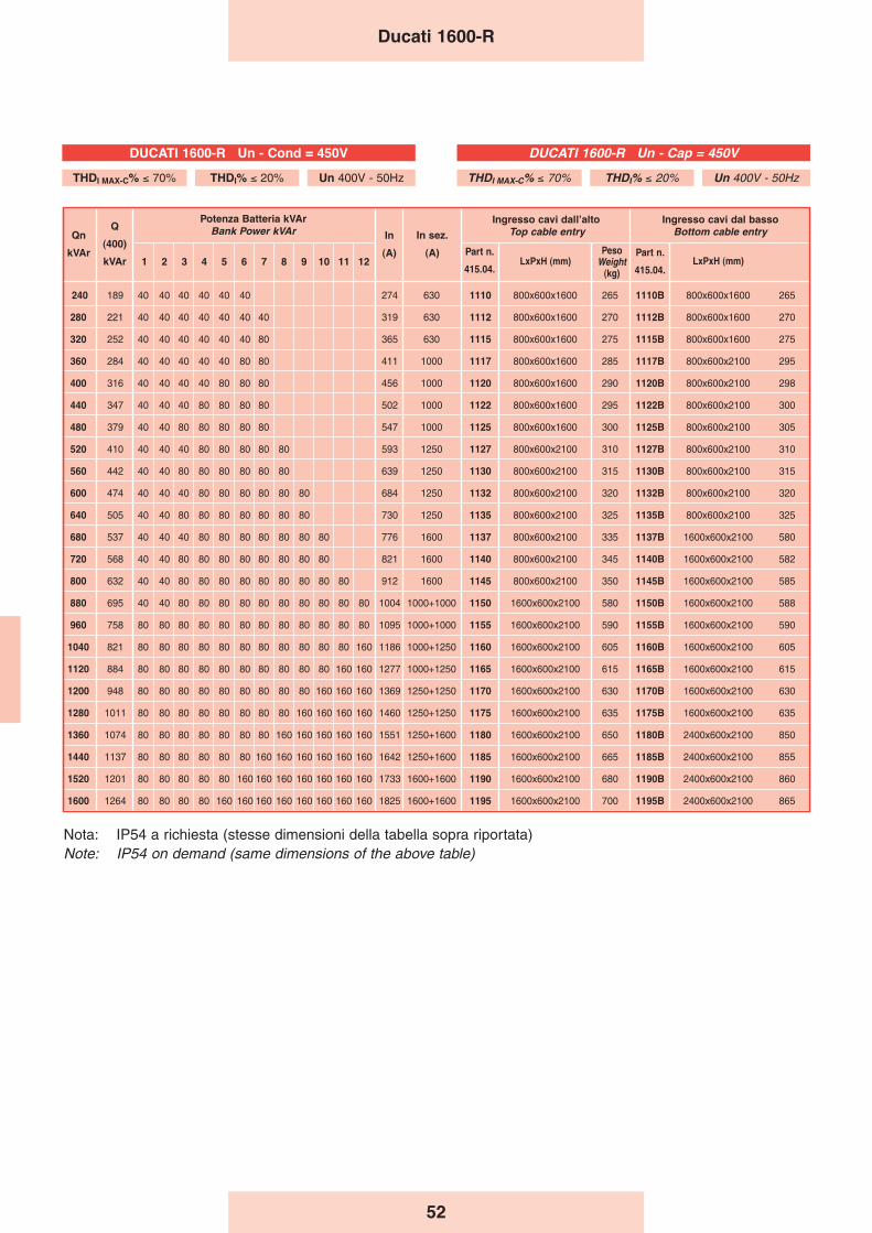
52
Ducati 1600-R
240 189 40 40 40 40 40 40 274 630 1110 800x600x1600 265 1110B 800x600x1600 265
280 221 40 40 40 40 40 40 40 319 630 1112 800x600x1600 270 1112B 800x600x1600 270
320 252 40 40 40 40 40 40 80 365 630 1115 800x600x1600 275 1115B 800x600x1600 275
360 284 40 40 40 40 40 80 80 411 1000 1117 800x600x1600 285 1117B 800x600x2100 295
400 316 40 40 40 40 80 80 80 456 1000 1120 800x600x1600 290 1120B 800x600x2100 298
440 347 40 40 40 80 80 80 80 502 1000 1122 800x600x1600 295 1122B 800x600x2100 300
480 379 40 40 80 80 80 80 80 547 1000 1125 800x600x1600 300 1125B 800x600x2100 305
520 410 40 40 40 80 80 80 80 80 593 1250 1127 800x600x2100 310 1127B 800x600x2100 310
560 442 40 40 80 80 80 80 80 80 639 1250 1130 800x600x2100 315 1130B 800x600x2100 315
600 474 40 40 40 80 80 80 80 80 80 684 1250 1132 800x600x2100 320 1132B 800x600x2100 320
640 505 40 40 80 80 80 80 80 80 80 730 1250 1135 800x600x2100 325 1135B 800x600x2100 325
680 537 40 40 40 80 80 80 80 80 80 80 776 1600 1137 800x600x2100 335 1137B 1600x600x2100 580
720 568 40 40 80 80 80 80 80 80 80 80 821 1600 1140 800x600x2100 345 1140B 1600x600x2100 582
800 632 40 40 80 80 80 80 80 80 80 80 80 912 1600 1145 800x600x2100 350 1145B 1600x600x2100 585
880 695 40 40 80 80 80 80 80 80 80 80 80 80 1004 1000+1000 1150 1600x600x2100 580 1150B 1600x600x2100 588
960 758 80 80 80 80 80 80 80 80 80 80 80 80 1095 1000+1000 1155 1600x600x2100 590 1155B 1600x600x2100 590
1040 821 80 80 80 80 80 80 80 80 80 80 80 160 1186 1000+1250 1160 1600x600x2100 605 1160B 1600x600x2100 605
1120 884 80 80 80 80 80 80 80 80 80 80 160 160 1277 1000+1250 1165 1600x600x2100 615 1165B 1600x600x2100 615
1200 948 80 80 80 80 80 80 80 80 80 160 160 160 1369 1250+1250 1170 1600x600x2100 630 1170B 1600x600x2100 630
1280 1011 80 80 80 80 80 80 80 80 160 160 160 160 1460 1250+1250 1175 1600x600x2100 635 1175B 1600x600x2100 635
1360 1074 80 80 80 80 80 80 80 160 160 160 160 160 1551 1250+1600 1180 1600x600x2100 650 1180B 2400x600x2100 850
1440 1137 80 80 80 80 80 80 160 160 160 160 160 160 1642 1250+1600 1185 1600x600x2100 665 1185B 2400x600x2100 855
1520 1201 80 80 80 80 80 160 160 160 160 160 160 160 1733 1600+1600 1190 1600x600x2100 680 1190B 2400x600x2100 860
1600 1264 80 80 80 80 160 160 160 160 160 160 160 160 1825 1600+1600 1195 1600x600x2100 700 1195B 2400x600x2100 865
Ingresso cavi dal bassoBottom cable entry
PesoWeight
(kg)
Qn
kVAr
Q
(400)
kVAr
Potenza Batteria kVArBank Power kVAr
1 2 3 4 5 6 7 8 9 10 11 12
In
(A)
In sez.
(A) Part n.
415.04.
Ingresso cavi dallʼaltoTop cable entry
LxPxH (mm)Part n.
415.04.LxPxH (mm)
Nota: IP54 a richiesta (stesse dimensioni della tabella sopra riportata)Note: IP54 on demand (same dimensions of the above table)
DUCATI 1600-R Un - Cap = 450V
THDI MAX-C% ≤ 70% THDI% ≤ 20% Un 400V - 50Hz
DUCATI 1600-R Un - Cond = 450V
THDI MAX-C% ≤ 70% THDI% ≤ 20% Un 400V - 50Hz
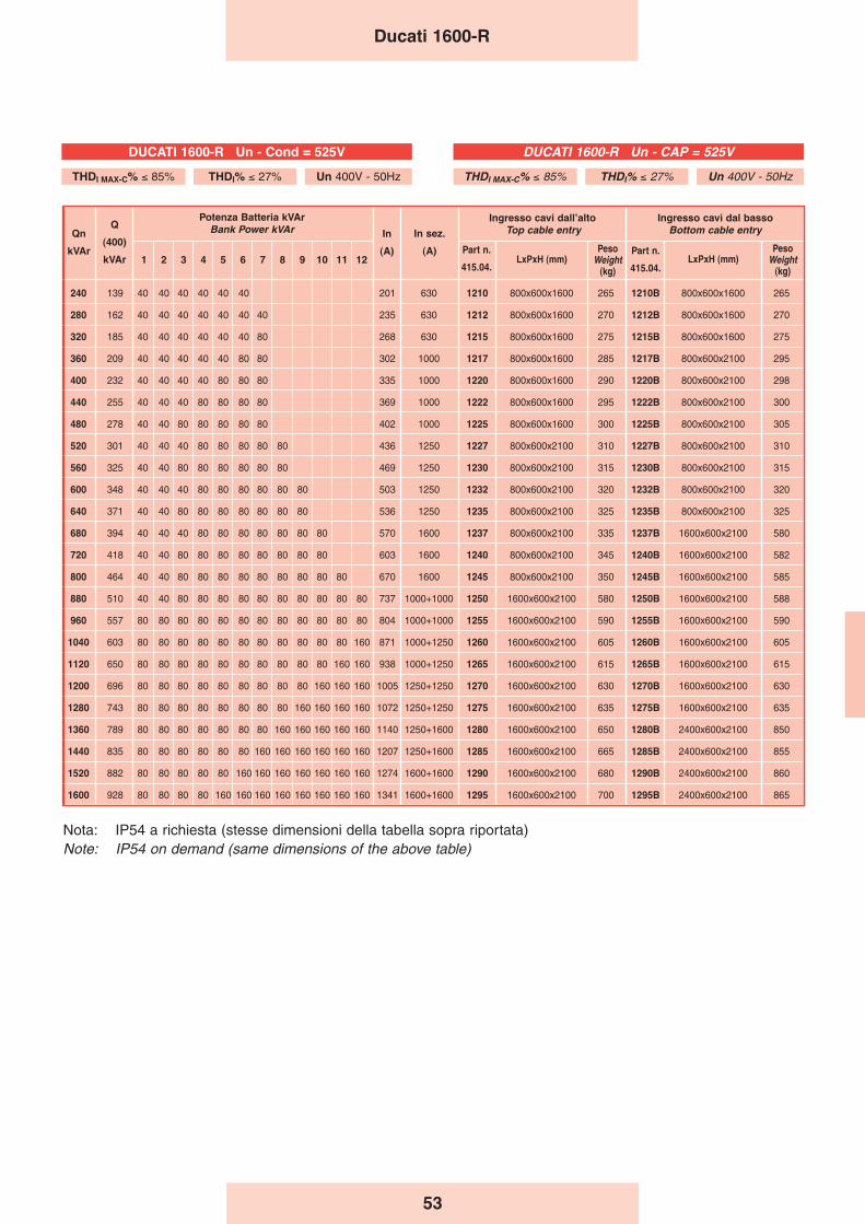
53
PesoWeight
(kg)
Ducati 1600-R
240 139 40 40 40 40 40 40 201 630 1210 800x600x1600 265 1210B 800x600x1600 265
280 162 40 40 40 40 40 40 40 235 630 1212 800x600x1600 270 1212B 800x600x1600 270
320 185 40 40 40 40 40 40 80 268 630 1215 800x600x1600 275 1215B 800x600x1600 275
360 209 40 40 40 40 40 80 80 302 1000 1217 800x600x1600 285 1217B 800x600x2100 295
400 232 40 40 40 40 80 80 80 335 1000 1220 800x600x1600 290 1220B 800x600x2100 298
440 255 40 40 40 80 80 80 80 369 1000 1222 800x600x1600 295 1222B 800x600x2100 300
480 278 40 40 80 80 80 80 80 402 1000 1225 800x600x1600 300 1225B 800x600x2100 305
520 301 40 40 40 80 80 80 80 80 436 1250 1227 800x600x2100 310 1227B 800x600x2100 310
560 325 40 40 80 80 80 80 80 80 469 1250 1230 800x600x2100 315 1230B 800x600x2100 315
600 348 40 40 40 80 80 80 80 80 80 503 1250 1232 800x600x2100 320 1232B 800x600x2100 320
640 371 40 40 80 80 80 80 80 80 80 536 1250 1235 800x600x2100 325 1235B 800x600x2100 325
680 394 40 40 40 80 80 80 80 80 80 80 570 1600 1237 800x600x2100 335 1237B 1600x600x2100 580
720 418 40 40 80 80 80 80 80 80 80 80 603 1600 1240 800x600x2100 345 1240B 1600x600x2100 582
800 464 40 40 80 80 80 80 80 80 80 80 80 670 1600 1245 800x600x2100 350 1245B 1600x600x2100 585
880 510 40 40 80 80 80 80 80 80 80 80 80 80 737 1000+1000 1250 1600x600x2100 580 1250B 1600x600x2100 588
960 557 80 80 80 80 80 80 80 80 80 80 80 80 804 1000+1000 1255 1600x600x2100 590 1255B 1600x600x2100 590
1040 603 80 80 80 80 80 80 80 80 80 80 80 160 871 1000+1250 1260 1600x600x2100 605 1260B 1600x600x2100 605
1120 650 80 80 80 80 80 80 80 80 80 80 160 160 938 1000+1250 1265 1600x600x2100 615 1265B 1600x600x2100 615
1200 696 80 80 80 80 80 80 80 80 80 160 160 160 1005 1250+1250 1270 1600x600x2100 630 1270B 1600x600x2100 630
1280 743 80 80 80 80 80 80 80 80 160 160 160 160 1072 1250+1250 1275 1600x600x2100 635 1275B 1600x600x2100 635
1360 789 80 80 80 80 80 80 80 160 160 160 160 160 1140 1250+1600 1280 1600x600x2100 650 1280B 2400x600x2100 850
1440 835 80 80 80 80 80 80 160 160 160 160 160 160 1207 1250+1600 1285 1600x600x2100 665 1285B 2400x600x2100 855
1520 882 80 80 80 80 80 160 160 160 160 160 160 160 1274 1600+1600 1290 1600x600x2100 680 1290B 2400x600x2100 860
1600 928 80 80 80 80 160 160 160 160 160 160 160 160 1341 1600+1600 1295 1600x600x2100 700 1295B 2400x600x2100 865
Ingresso cavi dal bassoBottom cable entry
PesoWeight
(kg)
Qn
kVAr
Q
(400)
kVAr
Potenza Batteria kVArBank Power kVAr
1 2 3 4 5 6 7 8 9 10 11 12
In
(A)
In sez.
(A) Part n.
415.04.
Ingresso cavi dallʼaltoTop cable entry
LxPxH (mm)Part n.
415.04.LxPxH (mm)
PesoWeight
(kg)
Nota: IP54 a richiesta (stesse dimensioni della tabella sopra riportata)Note: IP54 on demand (same dimensions of the above table)
DUCATI 1600-R Un - CAP = 525V
THDI MAX-C% ≤ 85% THDI% ≤ 27% Un 400V - 50Hz
DUCATI 1600-R Un - Cond = 525V
THDI MAX-C% ≤ 85% THDI% ≤ 27% Un 400V - 50Hz
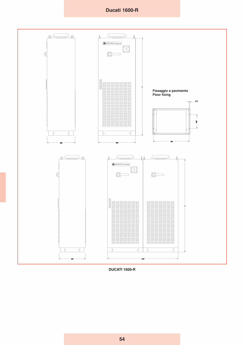
54
Ducati 1600-R
DUCATI 1600-R
Fissaggio a pavimentoFloor fixing

55
Apparecchiatureautomatichecon sistemi di filtro
Automatic equipmentwith filter system
A three-phase iron-core reactor is connected in series withthe various capacitor banks in this equipment. The reactorcontrols the harmonic component circulating, to prevent anyresonance.The unit resonance frequency is 190 Hz. This makes theequipment ideal for use in systems with fully-controlled SCRbridge converters generating 5th - 7th – 11th - 13th etc. levelharmonics.
The equipment must be used after the appropriate tests if thetype of loads suggests that there are 3rd level harmonicspresent. The current rating of the reactor, based on thefundamental component and on the permanent operatingand brief overloads 5th level harmonic component, allowscorrect system operation even under the most difficult mainsharmonic load conditions (30% of the 5th), keeping theinductance within the tolerances.
The harmonic component which will circulate in the LC unitsdepends not just on the load generated by the harmonics, butalso on the short-circuit power at the point where the bank isinstalled. Therefore, check the following:
SCC1––––––––– > 60
Q
PGAKW––––––––– < 3
Q
PGAKVA––––––––– < 4
Q
Alle varie batterie di condensatori di queste apparecchiatureè posto in serie un reattore trifase con nucleo in ferro, la cuifunzione è di controllare la componente armonica circolanteevitando il verificarsi di risonanze.La frequenza propria di risonanza del gruppo è di 189 Hz. Leapparecchiature sono quindi idonee ad essere utilizzatetipicamente negli impianti dove sono presenti convertitori aSCR a ponte totalcontrollato generanti armoniche di 5° - 7° -11° - 13° livello ecc...Devono essere usate dopo opportune verifiche qualora per iltipo di carichi si suppongono presenti armoniche di 3° livello.Il dimensionamento in corrente del reattore, basato sullacomponente fondamentale e sulla componente armonica di5° livello di funzionamento permanente e di sovraccarico perbrevi periodi, è tale da consentire il corretto funzionamentodel sistema anche nelle più gravose condizioni di caricoarmonico in rete (30% di 5ª) senza che il valore di induttanzasubisca variazioni superiori ai limiti di tolleranza.La componente armonica che circolerà nei gruppi LCdipende, oltre che dal carico che genera le armoniche, anchedalla potenza di cortocircuito nel punto di installazione dellabatteria ed è pertanto opportuno, in fase di studio, fare leseguenti verifiche:
SCC1––––––––– > 60
Q
PGAKW––––––––– < 3
Q
PGAKVA––––––––– < 4
Q
56
Where:- SCC1 = short-circuit power in KVA at the bank installation
point. If the value is unknown, the short-circuit power of thetransformers may be used:
where A is the transformer rated power (in kVA) and Vdc%is the transformer’s percentage short-circuit voltage.
- PGAKW = active power of the converter (e.g.: motors)- PGAKVA = apparent power of the converter (e.g.: UPS)- Q = power output of the capacitor bank in kVAr
If the above values are exceeded, more precise evaluationsare required to prevent the reactors from overheating.
Dove:- SCC1 = potenza di cortocircuito in KVA nel punto di
installazione della batteria. Se il valore non è noto, ci si puòriferire approssimativamente alla potenza di cortocircuito ditrasformatori:
dove A è la potenza nominale del trasformatore (espressain kVA) e Vcc% è la tensione di corto circuito percentualedel trasformatore.
- PGAKW = potenza attiva del convertitore (es. motori)- PGAKVA = Potenza apparente del convertitore (es. UPS)- Q = Potenza resa dal banco dei condensatori in kVAr
Qualora i valori suddetti siano superati è opportuno effettuarevalutazioni più precise per evitare il surriscaldamento deireattori.
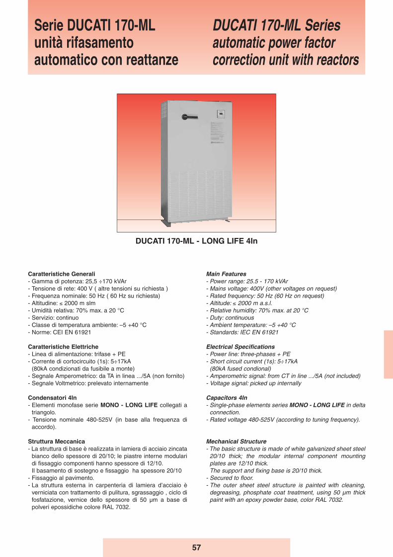
57
Serie DUCATI 170-MLunità rifasamentoautomatico con reattanze
DUCATI 170-ML Seriesautomatic power factorcorrection unit with reactors
DUCATI 170-ML - LONG LIFE 4In
Main Features- Power range: 25.5 - 170 kVAr - Mains voltage: 400V (other voltages on request)- Rated frequency: 50 Hz (60 Hz on request)- Altitude: ≤ 2000 m a.s.l.- Relative humidity: 70% max. at 20 °C- Duty: continuous- Ambient temperature: –5 +40 °C- Standards: IEC EN 61921
Electrical Specifications- Power line: three-phases + PE- Short circuit current (1s): 5÷17kA
(80kA fused condional)- Amperometric signal: from CT in line .../5A (not included)- Voltage signal: picked up internally
Capacitors 4In- Single-phase elements series MONO - LONG LIFE in delta
connection.- Rated voltage 480-525V (according to tuning frequency).
Mechanical Structure- The basic structure is made of white galvanized sheet steel
20/10 thick; the modular internal component mountingplates are 12/10 thick.The support and fixing base is 20/10 thick.
- Secured to floor.- The outer sheet steel structure is painted with cleaning,
degreasing, phosphate coat treatment, using 50 μm thickpaint with an epoxy powder base, color RAL 7032.
Caratteristiche Generali- Gamma di potenza: 25,5 ÷170 kVAr - Tensione di rete: 400 V ( altre tensioni su richiesta )- Frequenza nominale: 50 Hz ( 60 Hz su richiesta)- Altitudine: ≤ 2000 m slm- Umidità relativa: 70% max. a 20 °C- Servizio: continuo- Classe di temperatura ambiente: –5 +40 °C- Norme: CEI EN 61921
Caratteristiche Elettriche- Linea di alimentazione: trifase + PE- Corrente di cortocircuito (1s): 5÷17kA
(80kA condizionati da fusibile a monte)- Segnale Amperometrico: da TA in linea .../5A (non fornito)- Segnale Voltmetrico: prelevato internamente
Condensatori 4In- Elementi monofase serie MONO - LONG LIFE collegati a
triangolo.- Tensione nominale 480-525V (in base alla frequenza di
accordo).
Struttura Meccanica- La struttura di base è realizzata in lamiera di acciaio zincata
bianco dello spessore di 20/10; le piastre interne modularidi fissaggio componenti hanno spessore di 12/10.Il basamento di sostegno e fissaggio ha spessore 20/10
- Fissaggio al pavimento.- La struttura esterna in carpenteria di lamiera d’acciaio è
verniciata con trattamento di pulitura, sgrassaggio , ciclo difosfatazione, vernice dello spessore di 50 μm a base dipolveri epossidiche colore RAL 7032.

58
- Interno accessibile tramite portella interbloccata con ilsezionatore generale.
- Ventilazione forzata ottenuta tramite ventola (300m3 ora),posizionata nella parte sulla parte superiore della struttura
- Il grado di protezione è IP30 (IP superiori su richiesta).
Modalità dʼinstallazione- Per interno, a pavimento, in ambiente ventilato e non
polveroso, al riparo dalla luce diretta del sole.- Ingresso cavi dall’alto direttamente sui morsetti del
sezionatore
Sezionatore Generale- Sezionatore tripolare, con blocco porta e del tipo a velocità
indipendente da quella di manovra dell’operatore.- Corrente nominale del sezionatore 1,45 volte la corrente di
esercizio a 400 V.
Collegamenti Interni- Sistema di distribuzione interno realizzato con cavo tipo
N07V-K
Fusibili- A valle del sezionatore sono presenti più terne di fusibili,
posti a protezione delle batterie di condensatori.- I fusibili sono del tipo NH-00 con caratteristica GL.
Contattori- Adatti al comando di carichi capacitivi , inseriti all’esterno
del triangolo formato dagli elementi capacitivi monofase,dotati di un blocchetto trifase di contatti anticipati perl’inserzione dei dispositivi di limitazione della correnteall’inserzione.
- Tensione della bobina 230V, 50-60Hz.
Dispositivi di protezione- Ogni batteria di condensatori é dotata di dispositivi di scarica
atti a ridurre la tensione residua al di sotto del 10% dellatensione nominale del condensatore in circa 30 secondi.
Regolatore- Tipo REGO 5
Reattori di filtro armonico - frequenza di accordo: 189 Hz- linearità fino a 2 Ip/In- distorsione armonica in corrente ammessa in modo
continuativo: 30% In a 250 Hz; 15% In a 350 Hz- fattore di merito: Q > 20- materiali in classe H- sovratemperatura di funzionamento: 60 °C- protezione termica attraverso termistore con contatto NC.
Collaudo 100%Su ogni apparecchiatura automatica prodotta sono effettuatele seguenti prove e controlli:- Controllo visivo e dimensionale.- Controllo funzionamento meccanico.- Prova di tensione applicata verso massa sui circuiti di
potenza: 3kV per 1 minuto.- Controllo funzionamento elettrico a 400V, con controllo
della capacità totale delle batterie di condensatori installatesull’apparecchiatura automatica.
- Access to the inside is through a door with interlockingconnection to the main disconnecting switch.
- Forced ventilation obtained using a fan (300 m3/hour)located in the upper part of the structure.
- Protection level IP30 (higher IP optional).
Method of Installation- Indoor, on the floor, in a well-ventilated and dust-free
environment, protected from direct sunlight.- Top cable entry with direct connection to the terminals of
the disconnecting switches.
Main Disconnecting Switch- Three-pole disconnecting switch, with door lock and speed
independent of operator movement.- Disconnecting switch rated current 1.45 times the operating
current at 400V.
Internal Connections- Internal distribution system using N07V-K type cable.
Fuses- Downstream of the disconnecting switches there are
several triads of fuses, protecting the capacitor banks.- The fuses are of the NH-00 GL type.
Contactors- Suitable for controlling capacitive loads, inserted outside
the delta connection formed by the single-phase capacitiveelements, having a three-phase advance breaker block forinrush current limiting devices.
- Coil voltage 230V, 50-60Hz.
Protection devices- Each capacitor bank has discharge devices designed to
reduce the residual voltage below 10% of the capacitor’srated voltage in approximately 30 seconds.
Regulator- REGO 5 type.
Harmonic filter reactors- tuning frequency: 189 Hz- linearity up to 2 Ip/In- continuous current harmonic distortion allowed: 30% In at
250 Hz; 15% In at 350 Hz- Q-factor: Q > 20- materials in class H- operating overtemperature: 60 °C- thermal protection using a thermistor with NC contact.
100% TestingAll automatic equipment produced is subject to the followingtests and inspections:- Visual and dimensional inspection.- Mechanical operation test.- Insulation test, 3kV applied between phases and ground for
1 minute.- Test of electrical efficiency at 400V, with a check of total
capacitance of the capacitor banks installed on theautomatic equipment.
Ducati 170-ML
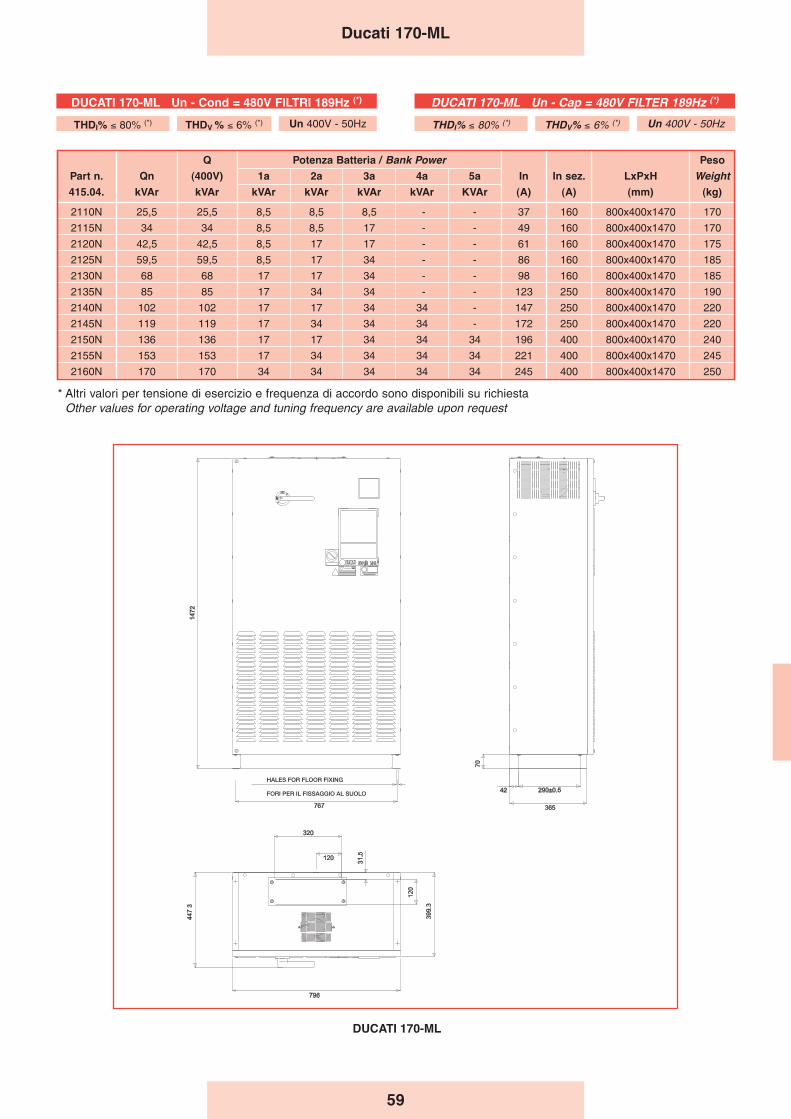
59
Q Potenza Batteria / Bank Power Peso
Part n. Qn (400V) 1a 2a 3a 4a 5a In In sez. LxPxH Weight415.04. kVAr kVAr kVAr kVAr kVAr kVAr KVAr (A) (A) (mm) (kg)
2110N 25,5 25,5 8,5 8,5 8,5 - - 37 160 800x400x1470 170
2115N 34 34 8,5 8,5 17 - - 49 160 800x400x1470 170
2120N 42,5 42,5 8,5 17 17 - - 61 160 800x400x1470 175
2125N 59,5 59,5 8,5 17 34 - - 86 160 800x400x1470 185
2130N 68 68 17 17 34 - - 98 160 800x400x1470 185
2135N 85 85 17 34 34 - - 123 250 800x400x1470 190
2140N 102 102 17 17 34 34 - 147 250 800x400x1470 220
2145N 119 119 17 34 34 34 - 172 250 800x400x1470 220
2150N 136 136 17 17 34 34 34 196 400 800x400x1470 240
2155N 153 153 17 34 34 34 34 221 400 800x400x1470 245
2160N 170 170 34 34 34 34 34 245 400 800x400x1470 250
Ducati 170-ML
DUCATI 170-ML Un - Cap = 480V FILTER 189Hz (*)
THDI% ≤ 80% (*) THDV% ≤ 6% (*) Un 400V - 50Hz
DUCATI 170-ML Un - Cond = 480V FILTRI 189Hz (*)
THDI% ≤ 80% (*) THDV % ≤ 6% (*) Un 400V - 50Hz
* Altri valori per tensione di esercizio e frequenza di accordo sono disponibili su richiesta Other values for operating voltage and tuning frequency are available upon request
DUCATI 170-ML
FORI PER IL FISSAGGIO AL SUOLO
HALES FOR FLOOR FIXING
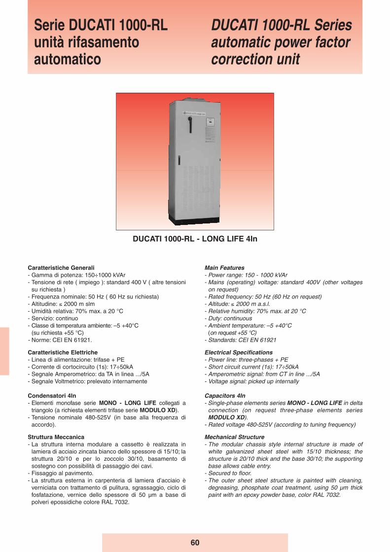
60
Caratteristiche Generali- Gamma di potenza: 150÷1000 kVAr - Tensione di rete ( impiego ): standard 400 V ( altre tensioni
su richiesta )- Frequenza nominale: 50 Hz ( 60 Hz su richiesta)- Altitudine: ≤ 2000 m slm- Umidità relativa: 70% max. a 20 °C- Servizio: continuo- Classe di temperatura ambiente: –5 +40°C
(su richiesta +55 °C)- Norme: CEI EN 61921.
Caratteristiche Elettriche- Linea di alimentazione: trifase + PE- Corrente di cortocircuito (1s): 17÷50kA - Segnale Amperometrico: da TA in linea .../5A- Segnale Voltmetrico: prelevato internamente
Condensatori 4In- Elementi monofase serie MONO - LONG LIFE collegati a
triangolo (a richiesta elementi trifase serie MODULO XD).- Tensione nominale 480-525V (in base alla frequenza di
accordo).
Struttura Meccanica- La struttura interna modulare a cassetto è realizzata in
lamiera di acciaio zincata bianco dello spessore di 15/10; lastruttura 20/10 e per lo zoccolo 30/10, basamento disostegno con possibilità di passaggio dei cavi.
- Fissaggio al pavimento.- La struttura esterna in carpenteria di lamiera d’acciaio è
verniciata con trattamento di pulitura, sgrassaggio, ciclo difosfatazione, vernice dello spessore di 50 μm a base dipolveri epossidiche colore RAL 7032.
Main Features- Power range: 150 - 1000 kVAr - Mains (operating) voltage: standard 400V (other voltages
on request)- Rated frequency: 50 Hz (60 Hz on request)- Altitude: ≤ 2000 m a.s.l.- Relative humidity: 70% max. at 20 °C- Duty: continuous- Ambient temperature: –5 +40°C
(on request +55 °C)- Standards: CEI EN 61921
Electrical Specifications- Power line: three-phases + PE- Short circuit current (1s): 17÷50kA - Amperometric signal: from CT in line .../5A- Voltage signal: picked up internally
Capacitors 4In- Single-phase elements series MONO - LONG LIFE in delta
connection (on request three-phase elements seriesMODULO XD).
- Rated voltage 480-525V (according to tuning frequency)
Mechanical Structure- The modular chassis style internal structure is made of
white galvanized sheet steel with 15/10 thickness; thestructure is 20/10 thick and the base 30/10; the supportingbase allows cable entry.
- Secured to floor.- The outer sheet steel structure is painted with cleaning,
degreasing, phosphate coat treatment, using 50 μm thickpaint with an epoxy powder base, color RAL 7032.
Serie DUCATI 1000-RLunità rifasamentoautomatico
DUCATI 1000-RL Seriesautomatic power factorcorrection unit
DUCATI 1000-RL - LONG LIFE 4In

61
Ducati 1000-RL
- Access to the inside is through a door with interlockingconnection to the main disconnecting switch.
- Forced ventilation obtained using a exhaust fan located inthe upper part of the structure.
- Top cable entry (bottom cable entry optional, withdimensions changing) with direct connection to the terminalsof the disconnecting switches (one switch per column).
- Protection level IP30 (higher IP optional).
Method of Installation- Inside, on the floor, in a well-ventilated and dust-free
environment, protected from direct sunlight.
Main Disconnecting Switch- Three-pole disconnecting switch for each column, with door
lock and speed independent of operator movement.- Disconnecting switch rated current 1.45 times the operating
current at 400 V.
Internal Connections- Internal distribution system using N07V-K type cable.
Fuses- Downstream of the disconnecting switches there are
several triads of fuses, protecting the capacitor banks.- The fuses are of the NH-00 GL type.
Contactors- Suitable for controlling capacitive loads, inserted outside
the delta connection formed by the single-phase capacitiveelements, having a three-phase advance breaker block forinrush current limiting devices.
- Coil voltage 230V, 50-60Hz.
Harmonic filter reactors- tuning frequency: 189 Hz- linearity up to 2 Ip/In- continuous current harmonic distortion allowed: 30% In at
250 Hz; 15% In at 350 Hz- Q-factor: Q > 20- materials in class H- operating overtemperature: 60 °C- thermal protection using a thermistor with NC contact.
Protection devices- Each capacitor bank has discharge devices designed to
reduce the residual voltage below 10% of the capacitor’srated voltage in approximately 30 seconds.
Regulator- REGO 7-12 type
100% TestingAll automatic equipment produced is subject to the followingtests and inspections:- Visual and dimensional inspection.- Mechanical operation test.- Insulation test, 3kV applied between phases and ground for
1 minute.- Test of electrical efficiency at 400V, with a check of total
capacitance of the capacitor banks installed on theautomatic equipment.
- Interno accessibile tramite portella interbloccata con ilsezionatore generale.
- Ventilazione forzata ottenuta tramite torrino di estrazione,posizionate nella parte superiore della struttura.
- Ingresso cavi dall’alto (dal basso a richiesta con aumentodelle dimensioni) direttamente sui morsetti dei sezionatori(un sezionatore per ogni colonna).
- Il grado di protezione è IP30 (IP superiori su richiesta).
Modalità dʼinstallazione- Per interno, a pavimento, in ambiente ventilato e non
polveroso, al riparo dalla luce diretta del sole.
Sezionatore Generale- Sezionatore tripolare per ogni colonna, con blocco porta e
del tipo a velocità indipendente da quella di manovradell’operatore.
- Corrente nominale del sezionatore 1,45 volte la corrente diesercizio a 400 V.
Collegamenti Interni- Sistema di distribuzione interno realizzato con cavo tipo
N07V-K
Fusibili- A valle del sezionatore sono presenti più terne di fusibili,
posti a protezione delle batterie di condensatori.- I fusibili sono del tipo NH-00 con caratteristica GL.
Contattori- Adatti al comando di carichi capacitivi, inseriti all’esterno del
triangolo formato dagli elementi capacitivi monofase, dotati diun blocchetto trifase di contatti anticipati per l’inserzione deidispositivi di limitazione della corrente all’inserzione.
- Tensione della bobina 230V, 50-60Hz.
Reattori di filtro armonico - frequenza di accordo: 189 Hz- linearità fino a 2 Ip/In- distorsione armonica in corrente ammessa in modo
continuativo: 30% In a 250 Hz; 15% In a 350 Hz- fattore di merito: Q > 20- materiali in classe H- sovratemperatura di funzionamento: 60 °C- protezione termica attraverso termistore con contatto NC.
Dispositivi di protezione- Ogni batteria di condensatori é dotata di dispositivi di scarica
atti a ridurre la tensione residua al di sotto del 10% dellatensione nominale del condensatore in circa 30 secondi.
Regolatore- Tipo REGO 7-12
Collaudo 100%Su ogni apparecchiatura automatica prodotta sono effettuatele seguenti prove e controlli:- Controllo visivo e dimensionale.- Controllo funzionamento meccanico.- Prova di tensione applicata verso massa sui circuiti di
potenza: 3kV per 1 minuto.- Controllo funzionamento elettrico a 400V, con controllo
della capacità totale delle batterie di condensatori installatesull’apparecchiatura automatica.
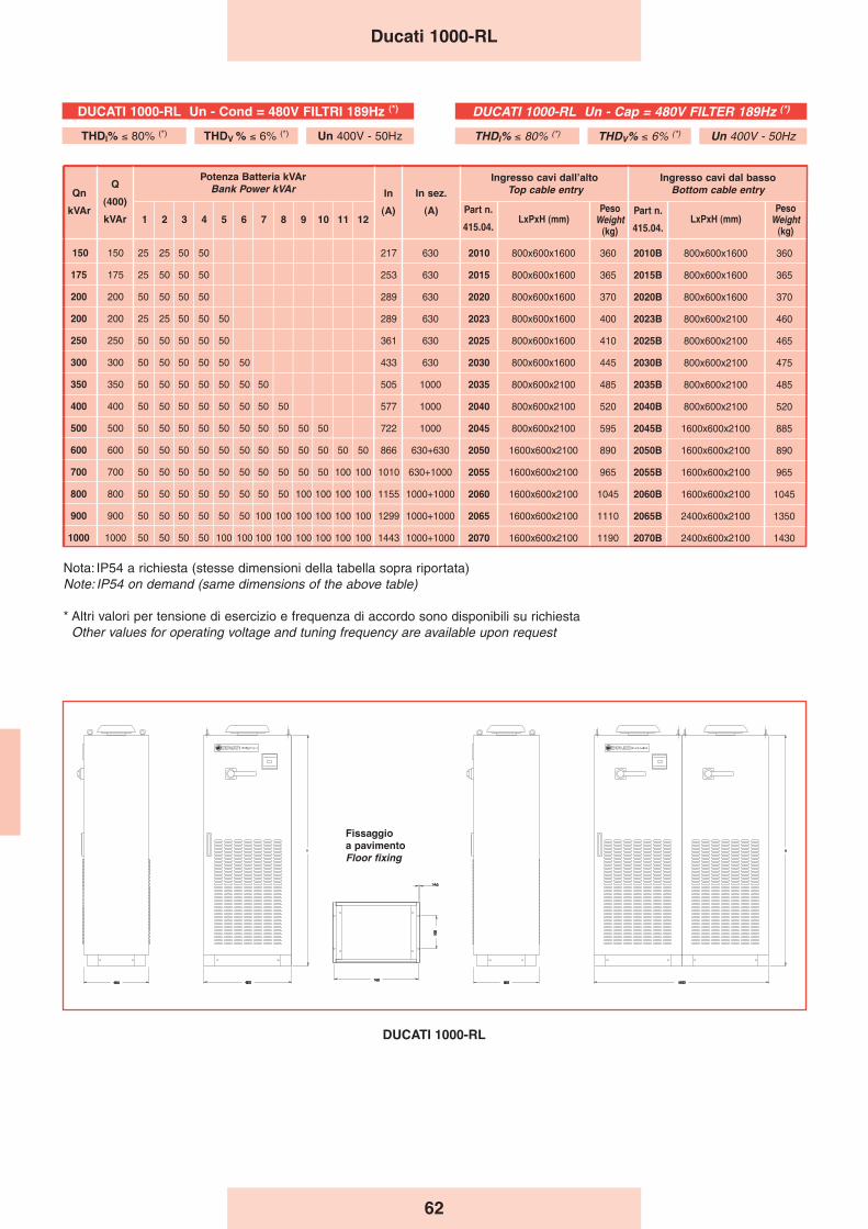
62
Ducati 1000-RL
150 150 25 25 50 50 217 630 2010 800x600x1600 360 2010B 800x600x1600 360
175 175 25 50 50 50 253 630 2015 800x600x1600 365 2015B 800x600x1600 365
200 200 50 50 50 50 289 630 2020 800x600x1600 370 2020B 800x600x1600 370
200 200 25 25 50 50 50 289 630 2023 800x600x1600 400 2023B 800x600x2100 460
250 250 50 50 50 50 50 361 630 2025 800x600x1600 410 2025B 800x600x2100 465
300 300 50 50 50 50 50 50 433 630 2030 800x600x1600 445 2030B 800x600x2100 475
350 350 50 50 50 50 50 50 50 505 1000 2035 800x600x2100 485 2035B 800x600x2100 485
400 400 50 50 50 50 50 50 50 50 577 1000 2040 800x600x2100 520 2040B 800x600x2100 520
500 500 50 50 50 50 50 50 50 50 50 50 722 1000 2045 800x600x2100 595 2045B 1600x600x2100 885
600 600 50 50 50 50 50 50 50 50 50 50 50 50 866 630+630 2050 1600x600x2100 890 2050B 1600x600x2100 890
700 700 50 50 50 50 50 50 50 50 50 50 100 100 1010 630+1000 2055 1600x600x2100 965 2055B 1600x600x2100 965
800 800 50 50 50 50 50 50 50 50 100 100 100 100 1155 1000+1000 2060 1600x600x2100 1045 2060B 1600x600x2100 1045
900 900 50 50 50 50 50 50 100 100 100 100 100 100 1299 1000+1000 2065 1600x600x2100 1110 2065B 2400x600x2100 1350
1000 1000 50 50 50 50 100 100 100 100 100 100 100 100 1443 1000+1000 2070 1600x600x2100 1190 2070B 2400x600x2100 1430
Ingresso cavi dal bassoBottom cable entry
PesoWeight
(kg)
Qn
kVAr
Q
(400)
kVAr
Potenza Batteria kVArBank Power kVAr
1 2 3 4 5 6 7 8 9 10 11 12
In
(A)
In sez.
(A) Part n.
415.04.
Ingresso cavi dallʼaltoTop cable entry
LxPxH (mm)Part n.
415.04.LxPxH (mm)
PesoWeight
(kg)
Nota: IP54 a richiesta (stesse dimensioni della tabella sopra riportata)Note: IP54 on demand (same dimensions of the above table)
* Altri valori per tensione di esercizio e frequenza di accordo sono disponibili su richiesta Other values for operating voltage and tuning frequency are available upon request
DUCATI 1000-RL Un - Cap = 480V FILTER 189Hz (*)
THDI% ≤ 80% (*) THDV% ≤ 6% (*) Un 400V - 50Hz
DUCATI 1000-RL Un - Cond = 480V FILTRI 189Hz (*)
THDI% ≤ 80% (*) THDV % ≤ 6% (*) Un 400V - 50Hz
DUCATI 1000-RL
Fissaggioa pavimentoFloor fixing
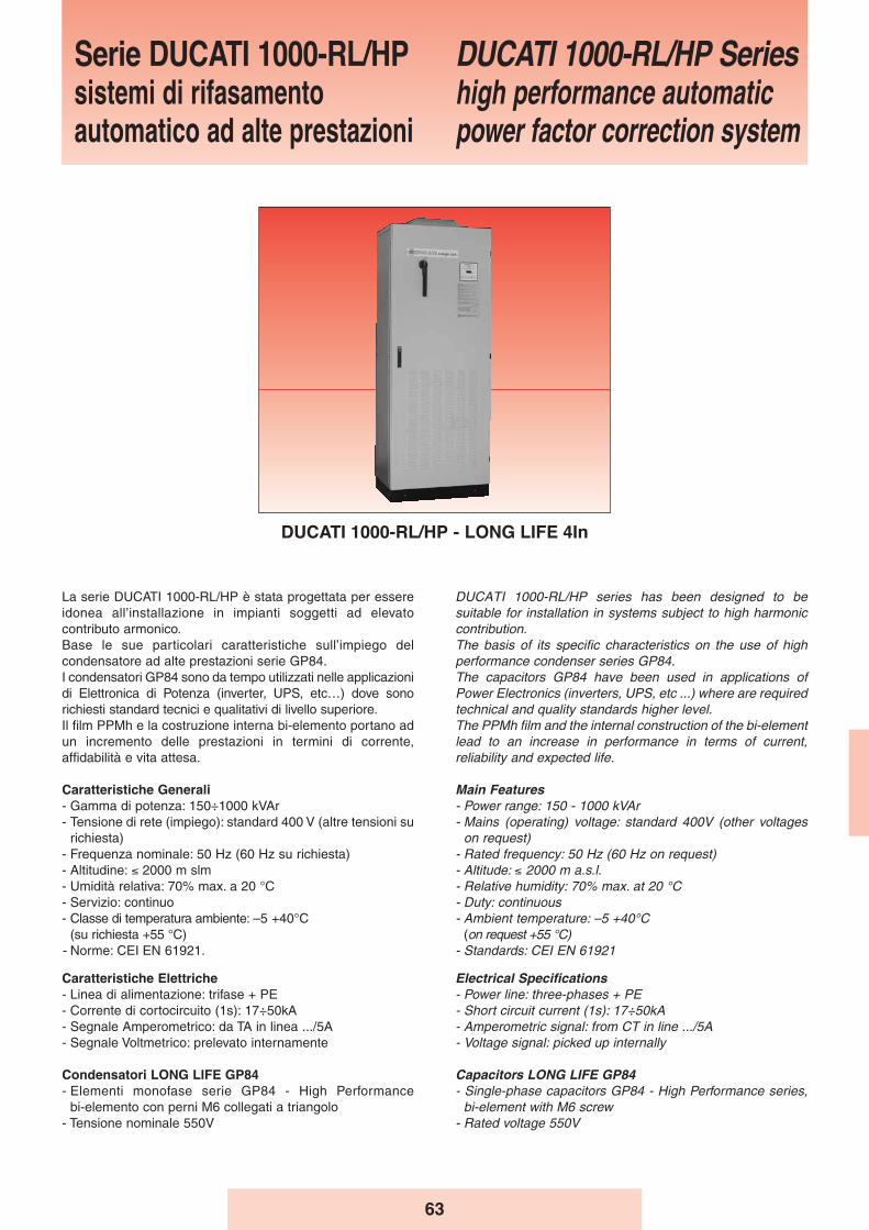
63
La serie DUCATI 1000-RL/HP è stata progettata per essereidonea all’installazione in impianti soggetti ad elevatocontributo armonico.Base le sue particolari caratteristiche sull’impiego delcondensatore ad alte prestazioni serie GP84.I condensatori GP84 sono da tempo utilizzati nelle applicazionidi Elettronica di Potenza (inverter, UPS, etc…) dove sonorichiesti standard tecnici e qualitativi di livello superiore.Il film PPMh e la costruzione interna bi-elemento portano adun incremento delle prestazioni in termini di corrente,affidabilità e vita attesa.
Caratteristiche Generali- Gamma di potenza: 150÷1000 kVAr - Tensione di rete (impiego): standard 400 V (altre tensioni su
richiesta)- Frequenza nominale: 50 Hz (60 Hz su richiesta)- Altitudine: ≤ 2000 m slm- Umidità relativa: 70% max. a 20 °C- Servizio: continuo- Classe di temperatura ambiente: –5 +40°C
(su richiesta +55 °C)- Norme: CEI EN 61921.
Caratteristiche Elettriche- Linea di alimentazione: trifase + PE- Corrente di cortocircuito (1s): 17÷50kA - Segnale Amperometrico: da TA in linea .../5A- Segnale Voltmetrico: prelevato internamente
Condensatori LONG LIFE GP84- Elementi monofase serie GP84 - High Performance
bi-elemento con perni M6 collegati a triangolo- Tensione nominale 550V
DUCATI 1000-RL/HP series has been designed to besuitable for installation in systems subject to high harmoniccontribution.The basis of its specific characteristics on the use of highperformance condenser series GP84.The capacitors GP84 have been used in applications ofPower Electronics (inverters, UPS, etc ...) where are requiredtechnical and quality standards higher level.The PPMh film and the internal construction of the bi-elementlead to an increase in performance in terms of current,reliability and expected life.
Main Features- Power range: 150 - 1000 kVAr - Mains (operating) voltage: standard 400V (other voltages
on request)- Rated frequency: 50 Hz (60 Hz on request)- Altitude: ≤ 2000 m a.s.l.- Relative humidity: 70% max. at 20 °C- Duty: continuous- Ambient temperature: –5 +40°C
(on request +55 °C)- Standards: CEI EN 61921
Electrical Specifications- Power line: three-phases + PE- Short circuit current (1s): 17÷50kA - Amperometric signal: from CT in line .../5A- Voltage signal: picked up internally
Capacitors LONG LIFE GP84- Single-phase capacitors GP84 - High Performance series,
bi-element with M6 screw- Rated voltage 550V
Serie DUCATI 1000-RL/HPsistemi di rifasamentoautomatico ad alte prestazioni
DUCATI 1000-RL/HP Serieshigh performance automaticpower factor correction system
DUCATI 1000-RL/HP - LONG LIFE 4In

64
Ducati 1000-RL/HP
Mechanical Structure- The modular chassis style internal structure is made of
white galvanized sheet steel with 15/10 thickness; thestructure is 20/10 thick and the base 30/10; the supportingbase allows cable entry.
- Secured to floor.- The outer sheet steel structure is painted with cleaning,
degreasing, phosphate coat treatment, using 50 μm thickpaint with an epoxy powder base, color RAL 7032.
- Access to the inside is through a door with interlockingconnection to the main disconnecting switch.
- Forced ventilation obtained using a exhaust fan located inthe upper part of the structure.
- Top cable entry (bottom cable entry optional, withdimensions changing) with direct connection to the terminalsof the disconnecting switches (one switch per column).
- Protection level IP30 (higher IP optional).
Method of Installation- Inside, on the floor, in a well-ventilated and dust-free
environment, protected from direct sunlight.
Main Disconnecting Switch- Three-pole disconnecting switch for each column, with door
lock and speed independent of operator movement.- Disconnecting switch rated current 1.45 times the operating
current at 400 V.
Internal Connections- Internal distribution system using N07V-K type cable.
Fuses- Downstream of the disconnecting switches there are
several triads of fuses, protecting the capacitor banks.- The fuses are of the NH-00 GL type.
Contactors- Suitable for controlling capacitive loads, inserted outside
the delta connection formed by the single-phase capacitiveelements, having a three-phase advance breaker block forinrush current limiting devices.
- Coil voltage 230 V, 50-60 Hz.
Harmonic filter reactors- tuning frequency: 189 Hz- linearity up to 2 Ip/In- continuous current harmonic distortion allowed: 40% In at
250 Hz; 25% In at 350 Hz- Q-factor: Q > 20- materials in class H- operating overtemperature: 60 °C- thermal protection using a thermistor with NC contact.
Protection devices- Each capacitor bank has discharge devices designed to
reduce the residual voltage below 10% of the capacitor’srated voltage in approximately 30 seconds.
Regulator- REGO 7-12 type
Struttura Meccanica- La struttura interna modulare a cassetto è realizzata in
lamiera di acciaio zincata bianco dello spessore di 15/10; lastruttura 20/10 e per lo zoccolo 30/10, basamento disostegno con possibilità di passaggio dei cavi.
- Fissaggio al pavimento.- La struttura esterna in carpenteria di lamiera d’acciaio è
verniciata con trattamento di pulitura, sgrassaggio, ciclo difosfatazione, vernice dello spessore di 50 μm a base dipolveri epossidiche colore RAL 7032.
- Interno accessibile tramite portella interbloccata con ilsezionatore generale.
- Ventilazione forzata ottenuta tramite torrino di estrazione,posizionate nella parte superiore della struttura.
- Ingresso cavi dall’alto (dal basso a richiesta con aumentodelle dimensioni) direttamente sui morsetti dei sezionatori(un sezionatore per ogni colonna).
- Il grado di protezione è IP30 (IP superiori su richiesta).
Modalità dʼinstallazione- Per interno, a pavimento, in ambiente ventilato e non
polveroso, al riparo dalla luce diretta del sole.
Sezionatore Generale- Sezionatore tripolare per ogni colonna, con blocco porta e
del tipo a velocità indipendente da quella di manovradell’operatore.
- Corrente nominale del sezionatore 1,45 volte la corrente diesercizio a 400 V.
Collegamenti Interni- Sistema di distribuzione interno realizzato con cavo tipo
N07V-K
Fusibili- A valle del sezionatore sono presenti più terne di fusibili,
posti a protezione delle batterie di condensatori.- I fusibili sono del tipo NH-00 con caratteristica GL.
Contattori- Adatti al comando di carichi capacitivi, inseriti all’esterno del
triangolo formato dagli elementi capacitivi monofase, dotati diun blocchetto trifase di contatti anticipati per l’inserzione deidispositivi di limitazione della corrente all’inserzione.
- Tensione della bobina 230 V, 50-60 Hz.
Reattori di filtro armonico - frequenza di accordo: 189 Hz- linearità fino a 2 Ip/In- distorsione armonica in corrente ammessa in modo
continuativo: 40% In a 250 Hz; 25% In a 350 Hz- fattore di merito: Q > 20- materiali in classe H- sovratemperatura di funzionamento: 60 °C- protezione termica attraverso termistore con contatto NC.
Dispositivi di protezione- Ogni batteria di condensatori é dotata di dispositivi di scarica
atti a ridurre la tensione residua al di sotto del 10% dellatensione nominale del condensatore in circa 30 secondi.
Regolatore- Tipo REGO 7-12
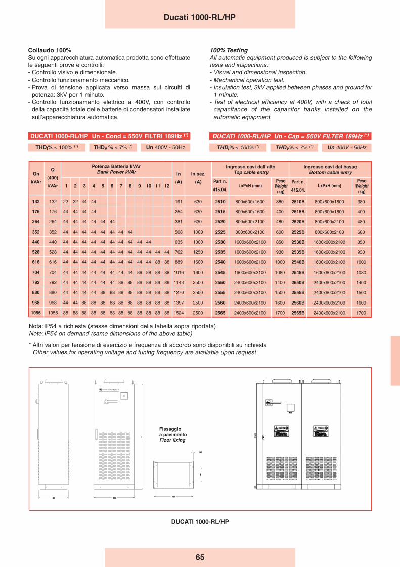
65
Ducati 1000-RL/HP
100% TestingAll automatic equipment produced is subject to the followingtests and inspections:- Visual and dimensional inspection.- Mechanical operation test.- Insulation test, 3kV applied between phases and ground for
1 minute.- Test of electrical efficiency at 400V, with a check of total
capacitance of the capacitor banks installed on theautomatic equipment.
Collaudo 100%Su ogni apparecchiatura automatica prodotta sono effettuatele seguenti prove e controlli:- Controllo visivo e dimensionale.- Controllo funzionamento meccanico.- Prova di tensione applicata verso massa sui circuiti di
potenza: 3kV per 1 minuto.- Controllo funzionamento elettrico a 400V, con controllo
della capacità totale delle batterie di condensatori installatesull’apparecchiatura automatica.
132 132 22 22 44 44 191 630 2510 800x600x1600 380 2510B 800x600x1600 380
176 176 44 44 44 44 254 630 2515 800x600x1600 400 2515B 800x600x1600 400
264 264 44 44 44 44 44 44 381 630 2520 800x600x2100 480 2520B 800x600x2100 480
352 352 44 44 44 44 44 44 44 44 508 1000 2525 800x600x2100 600 2525B 800x600x2100 600
440 440 44 44 44 44 44 44 44 44 44 44 635 1000 2530 1600x600x2100 850 2530B 1600x600x2100 850
528 528 44 44 44 44 44 44 44 44 44 44 44 44 762 1250 2535 1600x600x2100 930 2535B 1600x600x2100 930
616 616 44 44 44 44 44 44 44 44 44 44 88 88 889 1600 2540 1600x600x2100 1000 2540B 1600x600x2100 1000
704 704 44 44 44 44 44 44 44 44 88 88 88 88 1016 1600 2545 1600x600x2100 1080 2545B 1600x600x2100 1080
792 792 44 44 44 44 44 44 88 88 88 88 88 88 1143 2500 2550 2400x600x2100 1400 2550B 2400x600x2100 1400
880 880 44 44 44 44 88 88 88 88 88 88 88 88 1270 2500 2555 2400x600x2100 1500 2555B 2400x600x2100 1500
968 968 44 44 88 88 88 88 88 88 88 88 88 88 1397 2500 2560 2400x600x2100 1600 2560B 2400x600x2100 1600
1056 1056 88 88 88 88 88 88 88 88 88 88 88 88 1524 2500 2565 2400x600x2100 1700 2565B 2400x600x2100 1700
Ingresso cavi dal bassoBottom cable entry
PesoWeight
(kg)
Qn
kVAr
Q
(400)
kVAr
Potenza Batteria kVArBank Power kVAr
1 2 3 4 5 6 7 8 9 10 11 12
In
(A)
In sez.
(A) Part n.
415.04.
Ingresso cavi dallʼaltoTop cable entry
LxPxH (mm)Part n.
415.04.LxPxH (mm)
PesoWeight
(kg)
Nota: IP54 a richiesta (stesse dimensioni della tabella sopra riportata)Note: IP54 on demand (same dimensions of the above table)
* Altri valori per tensione di esercizio e frequenza di accordo sono disponibili su richiesta Other values for operating voltage and tuning frequency are available upon request
DUCATI 1000-RL/HP Un - Cap = 550V FILTER 189Hz (*)
THDI% ≤ 100% (*) THDV% ≤ 7% (*) Un 400V - 50Hz
DUCATI 1000-RL/HP Un - Cond = 550V FILTRI 189Hz (*)
THDI% ≤ 100% (*) THDV % ≤ 7% (*) Un 400V - 50Hz
DUCATI 1000-RL/HP
Fissaggioa pavimentoFloor fixing
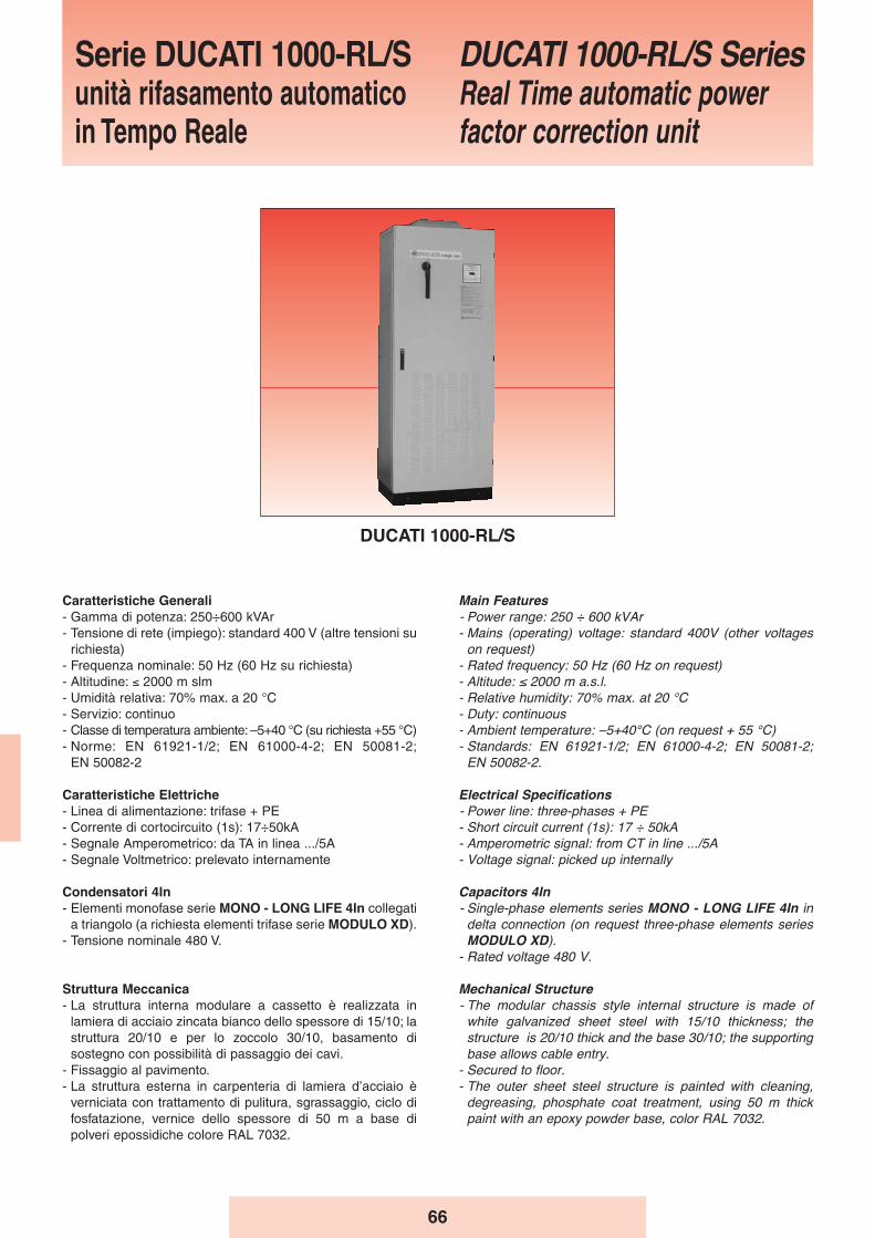
66
Caratteristiche Generali- Gamma di potenza: 250÷600 kVAr- Tensione di rete (impiego): standard 400 V (altre tensioni su
richiesta)- Frequenza nominale: 50 Hz (60 Hz su richiesta)- Altitudine: ≤ 2000 m slm- Umidità relativa: 70% max. a 20 °C- Servizio: continuo- Classe di temperatura ambiente: –5+40 °C (su richiesta +55 °C)- Norme: EN 61921-1/2; EN 61000-4-2; EN 50081-2;
EN 50082-2
Caratteristiche Elettriche- Linea di alimentazione: trifase + PE- Corrente di cortocircuito (1s): 17÷50kA- Segnale Amperometrico: da TA in linea .../5A- Segnale Voltmetrico: prelevato internamente
Condensatori 4In- Elementi monofase serie MONO - LONG LIFE 4In collegati
a triangolo (a richiesta elementi trifase serie MODULO XD).- Tensione nominale 480 V.
Struttura Meccanica- La struttura interna modulare a cassetto è realizzata in
lamiera di acciaio zincata bianco dello spessore di 15/10; lastruttura 20/10 e per lo zoccolo 30/10, basamento disostegno con possibilità di passaggio dei cavi.
- Fissaggio al pavimento.- La struttura esterna in carpenteria di lamiera d’acciaio è
verniciata con trattamento di pulitura, sgrassaggio, ciclo difosfatazione, vernice dello spessore di 50 m a base dipolveri epossidiche colore RAL 7032.
Main Features- Power range: 250 ÷ 600 kVAr- Mains (operating) voltage: standard 400V (other voltages
on request)- Rated frequency: 50 Hz (60 Hz on request)- Altitude: ≤ 2000 m a.s.l.- Relative humidity: 70% max. at 20 °C- Duty: continuous- Ambient temperature: –5+40°C (on request + 55 °C)- Standards: EN 61921-1/2; EN 61000-4-2; EN 50081-2;
EN 50082-2.
Electrical Specifications- Power line: three-phases + PE- Short circuit current (1s): 17 ÷ 50kA- Amperometric signal: from CT in line .../5A- Voltage signal: picked up internally
Capacitors 4In- Single-phase elements series MONO - LONG LIFE 4In in
delta connection (on request three-phase elements seriesMODULO XD).
- Rated voltage 480 V.
Mechanical Structure- The modular chassis style internal structure is made of
white galvanized sheet steel with 15/10 thickness; thestructure is 20/10 thick and the base 30/10; the supportingbase allows cable entry.
- Secured to floor.- The outer sheet steel structure is painted with cleaning,
degreasing, phosphate coat treatment, using 50 m thickpaint with an epoxy powder base, color RAL 7032.
Serie DUCATI 1000-RL/Sunità rifasamento automaticoin Tempo Reale
DUCATI 1000-RL/S SeriesReal Time automatic powerfactor correction unit
DUCATI 1000-RL/S
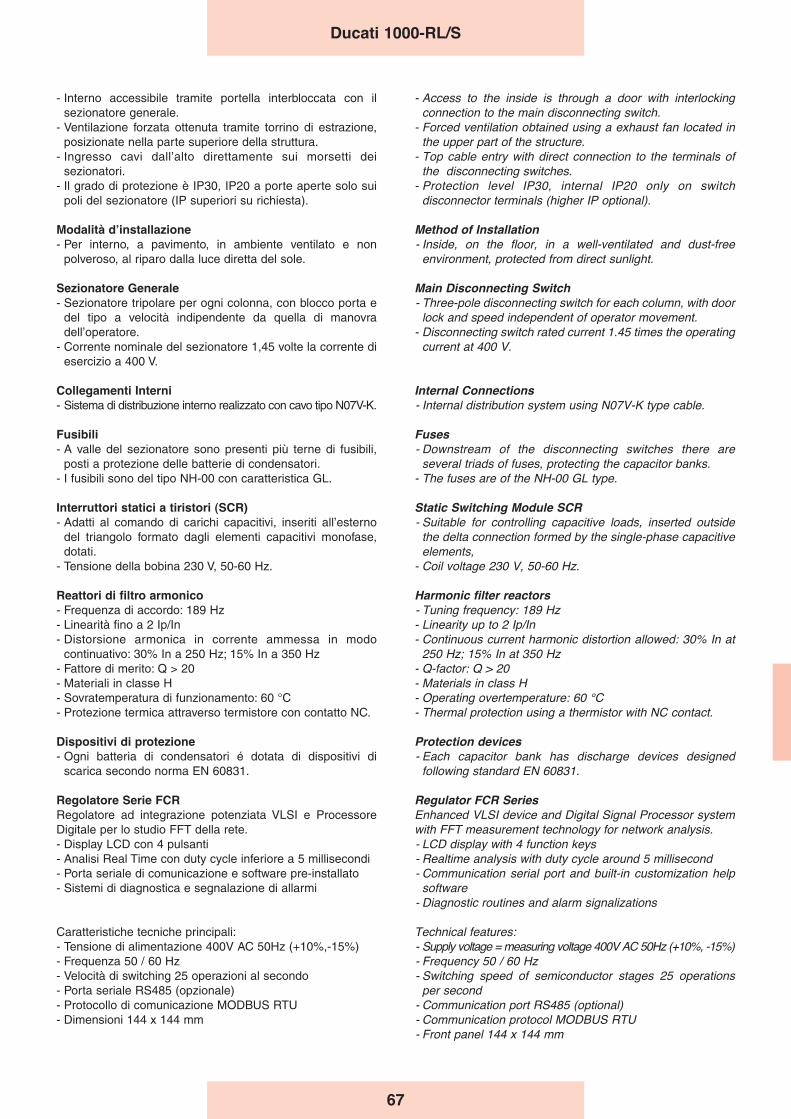
67
- Interno accessibile tramite portella interbloccata con ilsezionatore generale.
- Ventilazione forzata ottenuta tramite torrino di estrazione,posizionate nella parte superiore della struttura.
- Ingresso cavi dall’alto direttamente sui morsetti deisezionatori.
- Il grado di protezione è IP30, IP20 a porte aperte solo suipoli del sezionatore (IP superiori su richiesta).
Modalità dʼinstallazione- Per interno, a pavimento, in ambiente ventilato e non
polveroso, al riparo dalla luce diretta del sole.
Sezionatore Generale- Sezionatore tripolare per ogni colonna, con blocco porta e
del tipo a velocità indipendente da quella di manovradell’operatore.
- Corrente nominale del sezionatore 1,45 volte la corrente diesercizio a 400 V.
Collegamenti Interni- Sistema di distribuzione interno realizzato con cavo tipo N07V-K.
Fusibili- A valle del sezionatore sono presenti più terne di fusibili,
posti a protezione delle batterie di condensatori.- I fusibili sono del tipo NH-00 con caratteristica GL.
Interruttori statici a tiristori (SCR)- Adatti al comando di carichi capacitivi, inseriti all’esterno
del triangolo formato dagli elementi capacitivi monofase,dotati.
- Tensione della bobina 230 V, 50-60 Hz.
Reattori di filtro armonico- Frequenza di accordo: 189 Hz- Linearità fino a 2 Ip/In- Distorsione armonica in corrente ammessa in modo
continuativo: 30% In a 250 Hz; 15% In a 350 Hz- Fattore di merito: Q > 20- Materiali in classe H- Sovratemperatura di funzionamento: 60 °C- Protezione termica attraverso termistore con contatto NC.
Dispositivi di protezione- Ogni batteria di condensatori é dotata di dispositivi di
scarica secondo norma EN 60831.
Regolatore Serie FCRRegolatore ad integrazione potenziata VLSI e ProcessoreDigitale per lo studio FFT della rete.- Display LCD con 4 pulsanti - Analisi Real Time con duty cycle inferiore a 5 millisecondi- Porta seriale di comunicazione e software pre-installato- Sistemi di diagnostica e segnalazione di allarmi
Caratteristiche tecniche principali:- Tensione di alimentazione 400V AC 50Hz (+10%,-15%)- Frequenza 50 / 60 Hz- Velocità di switching 25 operazioni al secondo- Porta seriale RS485 (opzionale)- Protocollo di comunicazione MODBUS RTU- Dimensioni 144 x 144 mm
- Access to the inside is through a door with interlockingconnection to the main disconnecting switch.
- Forced ventilation obtained using a exhaust fan located inthe upper part of the structure.
- Top cable entry with direct connection to the terminals ofthe disconnecting switches.
- Protection level IP30, internal IP20 only on switchdisconnector terminals (higher IP optional).
Method of Installation- Inside, on the floor, in a well-ventilated and dust-free
environment, protected from direct sunlight.
Main Disconnecting Switch- Three-pole disconnecting switch for each column, with door
lock and speed independent of operator movement.- Disconnecting switch rated current 1.45 times the operating
current at 400 V.
Internal Connections- Internal distribution system using N07V-K type cable.
Fuses- Downstream of the disconnecting switches there are
several triads of fuses, protecting the capacitor banks.- The fuses are of the NH-00 GL type.
Static Switching Module SCR- Suitable for controlling capacitive loads, inserted outside
the delta connection formed by the single-phase capacitiveelements,
- Coil voltage 230 V, 50-60 Hz.
Harmonic filter reactors- Tuning frequency: 189 Hz- Linearity up to 2 Ip/In- Continuous current harmonic distortion allowed: 30% In at
250 Hz; 15% In at 350 Hz- Q-factor: Q > 20- Materials in class H- Operating overtemperature: 60 °C- Thermal protection using a thermistor with NC contact.
Protection devices- Each capacitor bank has discharge devices designed
following standard EN 60831.
Regulator FCR SeriesEnhanced VLSI device and Digital Signal Processor systemwith FFT measurement technology for network analysis.- LCD display with 4 function keys- Realtime analysis with duty cycle around 5 millisecond- Communication serial port and built-in customization help
software- Diagnostic routines and alarm signalizations
Technical features:- Supply voltage = measuring voltage 400V AC 50Hz (+10%, -15%)- Frequency 50 / 60 Hz- Switching speed of semiconductor stages 25 operations
per second- Communication port RS485 (optional)- Communication protocol MODBUS RTU- Front panel 144 x 144 mm
Ducati 1000-RL/S
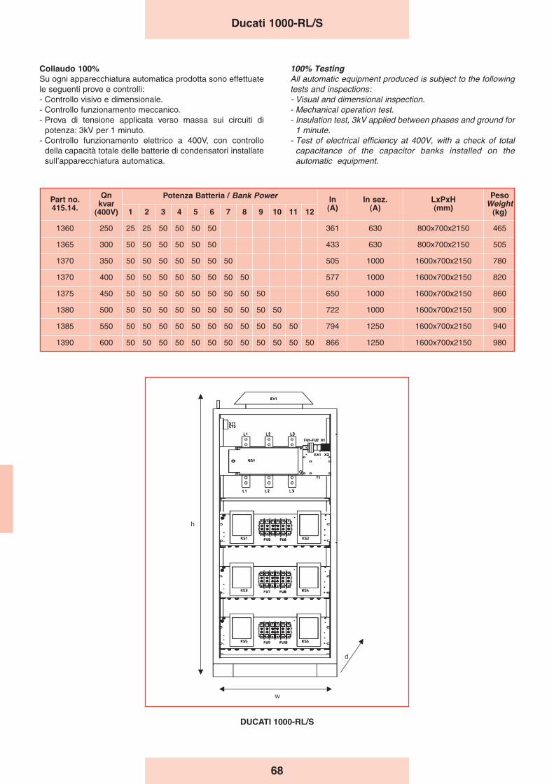
68
Ducati 1000-RL/S
DUCATI 1000-RL/S
h
d
w
Collaudo 100%Su ogni apparecchiatura automatica prodotta sono effettuatele seguenti prove e controlli:- Controllo visivo e dimensionale.- Controllo funzionamento meccanico.- Prova di tensione applicata verso massa sui circuiti di
potenza: 3kV per 1 minuto.- Controllo funzionamento elettrico a 400V, con controllo
della capacità totale delle batterie di condensatori installatesull’apparecchiatura automatica.
100% TestingAll automatic equipment produced is subject to the followingtests and inspections:- Visual and dimensional inspection.- Mechanical operation test.- Insulation test, 3kV applied between phases and ground for
1 minute.- Test of electrical efficiency at 400V, with a check of total
capacitance of the capacitor banks installed on theautomatic equipment.
Part no.415.14.
Qnkvar
(400V)
Potenza Batteria / Bank Power In(A)
In sez.(A)
LxPxH(mm)
PesoWeight
(kg)1 2 3 4 5 6 7 8 9 10 11 12
1360 250 25 25 50 50 50 50 361 630 800x700x2150 465
1365 300 50 50 50 50 50 50 433 630 800x700x2150 505
1370 350 50 50 50 50 50 50 50 505 1000 1600x700x2150 780
1370 400 50 50 50 50 50 50 50 50 577 1000 1600x700x2150 820
1375 450 50 50 50 50 50 50 50 50 50 650 1000 1600x700x2150 860
1380 500 50 50 50 50 50 50 50 50 50 50 722 1000 1600x700x2150 900
1385 550 50 50 50 50 50 50 50 50 50 50 50 794 1250 1600x700x2150 940
1390 600 50 50 50 50 50 50 50 50 50 50 50 50 866 1250 1600x700x2150 980
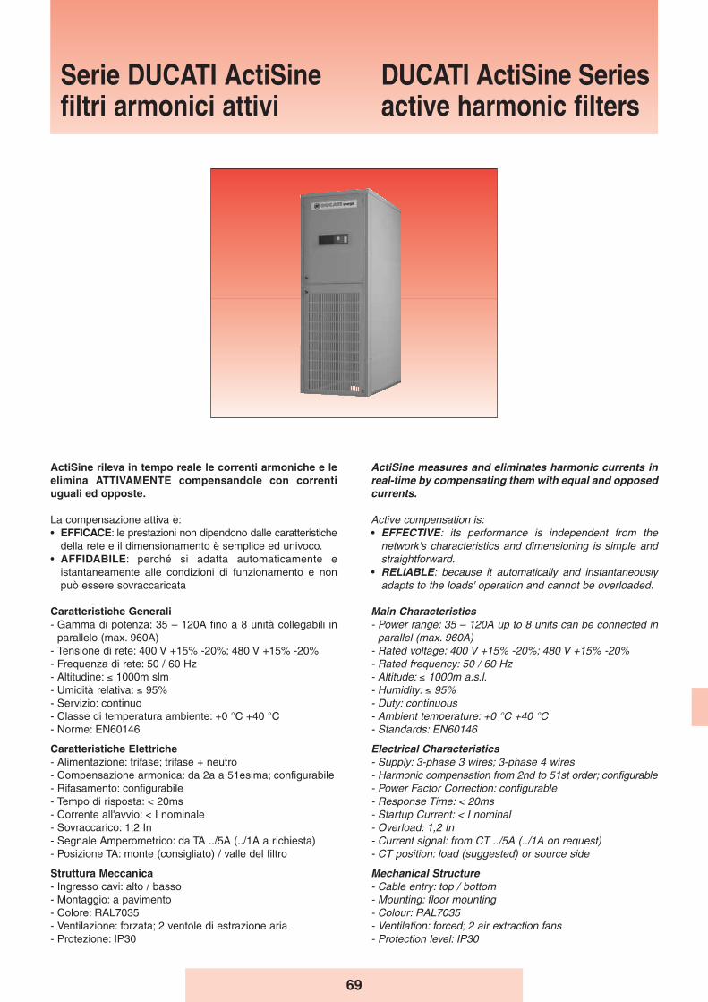
69
ActiSine measures and eliminates harmonic currents inreal-time by compensating them with equal and opposedcurrents.
Active compensation is:• EFFECTIVE: its performance is independent from the
network's characteristics and dimensioning is simple andstraightforward.
• RELIABLE: because it automatically and instantaneouslyadapts to the loads' operation and cannot be overloaded.
Main Characteristics- Power range: 35 – 120A up to 8 units can be connected in
parallel (max. 960A)- Rated voltage: 400 V +15% -20%; 480 V +15% -20%- Rated frequency: 50 / 60 Hz- Altitude: ≤ 1000m a.s.l.- Humidity: ≤ 95%- Duty: continuous- Ambient temperature: +0 °C +40 °C- Standards: EN60146
Electrical Characteristics- Supply: 3-phase 3 wires; 3-phase 4 wires- Harmonic compensation from 2nd to 51st order; configurable- Power Factor Correction: configurable- Response Time: < 20ms- Startup Current: < I nominal- Overload: 1,2 In- Current signal: from CT ../5A (../1A on request) - CT position: load (suggested) or source side
Mechanical Structure- Cable entry: top / bottom- Mounting: floor mounting- Colour: RAL7035- Ventilation: forced; 2 air extraction fans- Protection level: IP30
ActiSine rileva in tempo reale le correnti armoniche e leelimina ATTIVAMENTE compensandole con correntiuguali ed opposte.
La compensazione attiva è:• EFFICACE: le prestazioni non dipendono dalle caratteristiche
della rete e il dimensionamento è semplice ed univoco.• AFFIDABILE: perché si adatta automaticamente e
istantaneamente alle condizioni di funzionamento e nonpuò essere sovraccaricata
Caratteristiche Generali- Gamma di potenza: 35 – 120A fino a 8 unità collegabili in
parallelo (max. 960A)- Tensione di rete: 400 V +15% -20%; 480 V +15% -20%- Frequenza di rete: 50 / 60 Hz- Altitudine: ≤ 1000m slm- Umidità relativa: ≤ 95%- Servizio: continuo- Classe di temperatura ambiente: +0 °C +40 °C- Norme: EN60146
Caratteristiche Elettriche- Alimentazione: trifase; trifase + neutro- Compensazione armonica: da 2a a 51esima; configurabile- Rifasamento: configurabile- Tempo di risposta: < 20ms- Corrente all'avvio: < I nominale- Sovraccarico: 1,2 In- Segnale Amperometrico: da TA ../5A (../1A a richiesta)- Posizione TA: monte (consigliato) / valle del filtro
Struttura Meccanica- Ingresso cavi: alto / basso- Montaggio: a pavimento- Colore: RAL7035- Ventilazione: forzata; 2 ventole di estrazione aria- Protezione: IP30
Serie DUCATI ActiSinefiltri armonici attivi
DUCATI ActiSine Seriesactive harmonic filters
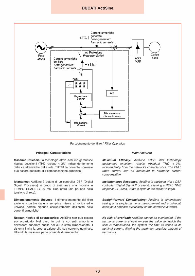
70
Main Features
Maximum Efficacy: ActiSine active filter technologyguarantees excellent results (residual THD < 3%)independently from the network's characteristics. The FULLrated current can be dedicated to harmonic currentcompensation.
Instantaneous Response: ActiSine is equipped with a DSPcontroller (Digital Signal Processor), assuring a REAL TIMEresponse (< 20ms, within a cycle of the mains voltage).
Straightforward Dimensioning: ActiSine is dimensionedbasing on a simple harmonic measurement and is univocal,because it depends exclusively on the harmonic currents.
No risk of overload: ActiSine cannot be overloaded. If theharmonic currents should exceed the value for which thefilter is dimensioned, the system will limit its action to itsnominal current, filtering the maximum possible amount ofharmonics.
Principali Caratteristiche
Massima Efficacia: la tecnologia attiva ActiSine garantiscerisultati eccellenti (THD residuo < 3%) indipendentementedalle caratteristiche della rete. TUTTA la corrente nominalepuò essere dedicata alla compensazione armonica.
Istantaneo: ActiSine è dotato di un controller DSP (DigitalSignal Processor) in grado di assicurare una risposta inTEMPO REALE (< 20 ms, cioè entro una periodo dellatensione di rete).
Dimensionamento Univoco: il dimensionamento del filtroavviene a partire da una semplice misura armonica ed èunivoco, perché dipende esclusivamente dall'entità dellecorrenti armoniche.
Nessun rischio di sovraccarico: ActiSine non può esseresovraccaricato. Nel caso in cui le correnti armonichedovessero superare quelle per cui è stato dimensionato, ilsistema limita la propria azione alla sua corrente nominale,filtrando la massima parte possibile di armoniche.
Funzionamento del filtro / Filter Operation
DUCATI ActiSine
71
Flessibilità e scalabilità: ActiSine abbina una strutturamodulare alla capacità di affiancare fino ad 8 unità inparallelo, per raggiungere potenze molto elevate. Questecaratteristiche assicurano la massima scalabilità in fase diinstallazione e l'espandibilità del sistema.
Filtraggio del Neutro: le armoniche di 3° ordine (e in modominore di ordine 9°, 15°, …, 6n+3) generate da carichidistorcenti mono-fase (PC, fotocopiatrici, ballast elettronici) sisommano nel neutro, sovraccaricandolo. ActiSine èdisponibile in versione trifase + neutro, in grado di filtrareefficacemente anche queste armoniche.
Selettività e Rifasamento: con le impostazioni di fabbrica,ActiSine agisce su tutte le armoniche, fino alla 51esima. Dalmenù utente può però essere impostata l'eliminazioneprioritaria di armoniche selezionate dall'utente (fino a 12),concentrando su di esse l'azione correttiva. ActiSine puòinoltre essere impostato per utilizzare parte della correntenominale per rifasare il carico e può però essere utilizzato incombinazione con i sistemi di rifasamento tradizionali –basati su banchi di condensatori – purché dotati di reattanzeanti-risonanza.
Semplicità di Installazione e Utilizzo: l'installazione diActiSine è semplice e flessibile perché viene collegato inparallelo ai carichi da filtrare e i TA per la misura delle correntipossono essere installati a monte o a valle del filtro (controlload anello chiuso o aperto). La messa in servizio è immediata,grazie alle impostazioni di default ed automatiche.L'interfaccia utente è semplice, immediata e completamentein ITALIANO.
Flexibility and expandability: ActiSine combines a modularstructure with the possibility of connecting up to 8 units inparallel, in order to obtain very high powers. Thesecharacteristics ensure the maximal flexibility duringinstallation and the expandability of the system.
Neutral Filtering: harmonics of 3rd order (and order 9th,15th, …, 6n+3) generated by single-phase distorting loads(PCs, copying machines, electronic ballasts) add up in theneutral cables, overloading them. ActiSine is available asthree-phase + neutral version, capable of effectivelycanceling these harmonics.
Selectivity and Power Factor Correction: with its defaultsettings ActiSine acts on all harmonics up to the 51st. Theuser can also set up to 12 harmonics on which to concentratethe filtering action. Moreover, ActiSine can be set to use partof its current to correct the load's power factor and can beused together with traditional capacitor-based PFCequipment, as long as they are equipped with detuningreactors.
Easy to Install and Operate: the installation is simple andflexible because ActiSine is connected in parallel to the loadsto be filtered and the CTs for the current measurement canbe mounted up- or down-stream (closed- or open-loopcontrol). The startup is immediate thanks to default andautomatic settings. The user interface is simple andstraightforward.
DUCATI ActiSine
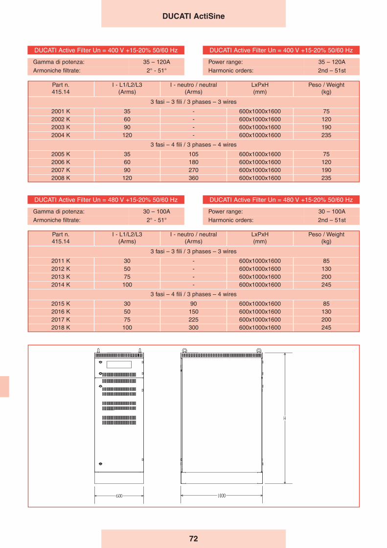
72
DUCATI ActiSine
DUCATI Active Filter Un = 400 V +15-20% 50/60 Hz
Gamma di potenza: 35 – 120A
Armoniche filtrate: 2° - 51°
DUCATI Active Filter Un = 400 V +15-20% 50/60 Hz
Power range: 35 – 120A
Harmonic orders: 2nd – 51st
DUCATI Active Filter Un = 480 V +15-20% 50/60 Hz
Gamma di potenza: 30 – 100A
Armoniche filtrate: 2° - 51°
DUCATI Active Filter Un = 480 V +15-20% 50/60 Hz
Power range: 30 – 100A
Harmonic orders: 2nd – 51st
Part n.415.14
I - L1/L2/L3(Arms)
I - neutro / neutral(Arms)
LxPxH(mm)
Peso / Weight(kg)
3 fasi – 3 fili / 3 phases – 3 wires
2001 K 35 - 600x1000x1600 752002 K 60 - 600x1000x1600 1202003 K 90 - 600x1000x1600 1902004 K 120 - 600x1000x1600 235
3 fasi – 4 fili / 3 phases – 4 wires
2005 K 35 105 600x1000x1600 752006 K 60 180 600x1000x1600 1202007 K 90 270 600x1000x1600 1902008 K 120 360 600x1000x1600 235
Part n.415.14
I - L1/L2/L3(Arms)
I - neutro / neutral(Arms)
LxPxH(mm)
Peso / Weight(kg)
3 fasi – 3 fili / 3 phases – 3 wires
2011 K 30 - 600x1000x1600 852012 K 50 - 600x1000x1600 1302013 K 75 - 600x1000x1600 2002014 K 100 - 600x1000x1600 245
3 fasi – 4 fili / 3 phases – 4 wires
2015 K 30 90 600x1000x1600 852016 K 50 150 600x1000x1600 1302017 K 75 225 600x1000x1600 2002018 K 100 300 600x1000x1600 245
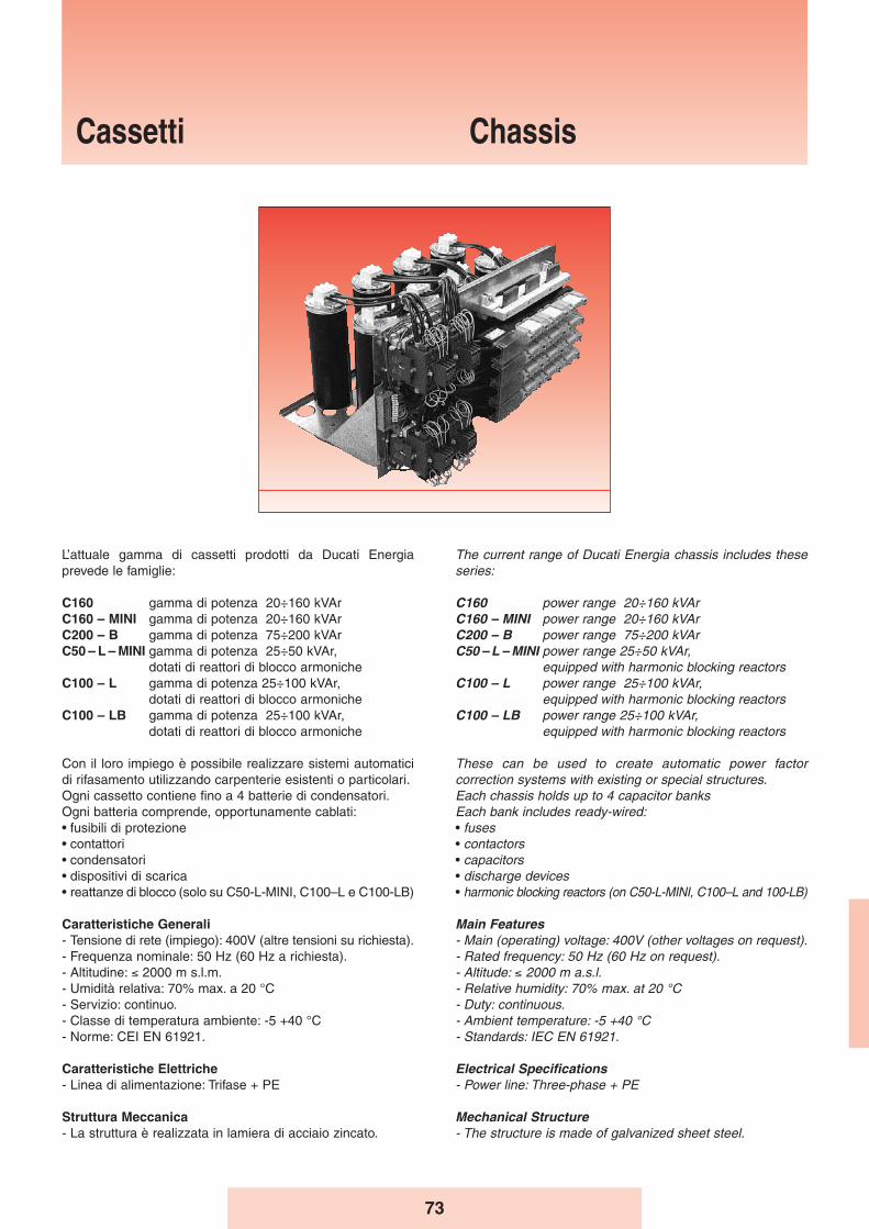
73
Cassetti Chassis
The current range of Ducati Energia chassis includes theseseries:
C160 power range 20÷160 kVAr C160 – MINI power range 20÷160 kVAr C200 – B power range 75÷200 kVAr C50 – L – MINI power range 25÷50 kVAr,
equipped with harmonic blocking reactorsC100 – L power range 25÷100 kVAr,
equipped with harmonic blocking reactorsC100 – LB power range 25÷100 kVAr,
equipped with harmonic blocking reactors
These can be used to create automatic power factorcorrection systems with existing or special structures.Each chassis holds up to 4 capacitor banks Each bank includes ready-wired:• fuses• contactors• capacitors• discharge devices• harmonic blocking reactors (on C50-L-MINI, C100–L and 100-LB)
Main Features- Main (operating) voltage: 400V (other voltages on request).- Rated frequency: 50 Hz (60 Hz on request).- Altitude: ≤ 2000 m a.s.l.- Relative humidity: 70% max. at 20 °C- Duty: continuous.- Ambient temperature: -5 +40 °C- Standards: IEC EN 61921.
Electrical Specifications- Power line: Three-phase + PE
Mechanical Structure- The structure is made of galvanized sheet steel.
L’attuale gamma di cassetti prodotti da Ducati Energiaprevede le famiglie:
C160 gamma di potenza 20÷160 kVAr C160 – MINI gamma di potenza 20÷160 kVAr C200 – B gamma di potenza 75÷200 kVAr C50 – L – MINI gamma di potenza 25÷50 kVAr,
dotati di reattori di blocco armonicheC100 – L gamma di potenza 25÷100 kVAr,
dotati di reattori di blocco armonicheC100 – LB gamma di potenza 25÷100 kVAr,
dotati di reattori di blocco armoniche
Con il loro impiego è possibile realizzare sistemi automaticidi rifasamento utilizzando carpenterie esistenti o particolari.Ogni cassetto contiene fino a 4 batterie di condensatori.Ogni batteria comprende, opportunamente cablati:• fusibili di protezione• contattori• condensatori• dispositivi di scarica• reattanze di blocco (solo su C50-L-MINI, C100–L e C100-LB)
Caratteristiche Generali- Tensione di rete (impiego): 400V (altre tensioni su richiesta).- Frequenza nominale: 50 Hz (60 Hz a richiesta).- Altitudine: ≤ 2000 m s.l.m.- Umidità relativa: 70% max. a 20 °C- Servizio: continuo.- Classe di temperatura ambiente: -5 +40 °C- Norme: CEI EN 61921.
Caratteristiche Elettriche- Linea di alimentazione: Trifase + PE
Struttura Meccanica- La struttura è realizzata in lamiera di acciaio zincato.
74
Capacitors 4In- Single-fase elements series MONO - LONG LIFE in delta
connection for C160, C160-MINI, C50-L-MINI, C100-L- Three-phase elements series MODULO XD for C200-B
and C100-LB (on request they can be supplied also forC160, C160-MINI and C100-L series)
- Rated voltage415-450-525V for C160 family400-525V for C200-B family480-525V for C50-L-MINI, C100-L and C100-LB family (according to the tuning frequency)
Installation method- Indoor, horizontal.
Internal Connections- Connections use N07VK cables.
Fuses- Triads of fuses protect each pair of capacitor banks.- The fuses are of the NH-00 GL type.
Contactors- Suitable for controlling capacitive loads, inserted outside
the delta connection formed by the single-phase capacitiveelements, having a three-phase advance breaker block forinrush current limiting devices.
- Coil voltage 230V, 50-60Hz.
Protection devices- Each capacitor bank has discharge devices designed to
reduce the residual voltage below 10% of the capacitor’srated voltage in approximately 30 seconds.
100% TestingAll automatic equipment produced is subject to the followingtests and inspections:- Visual and dimensional inspection.- Mechanical operation test.- Insulation test, 3kV applied between phases and ground for
1 minute.- Test of electrical efficiency at 400V, with a check of total
capacitance of the capacitor banks installed on theautomatic equipment..
Harmonic filter reactors (only for C50–L-Mini, C100–Land C100–LB)- tuning frequency: 189 Hz- linearity up to 2 Ip/In- continuous current harmonic distortion allowed: 30% In at
250 Hz; 15% In at 350 Hz- Q-factor: Q > 20- materials in class H- operating overtemperature: 60 °C- thermal protection using a thermistor with NC contact.
Cassetti - Chassis
Condensatori 4In- Elementi monofase serie MONO - LONG LIFE collegati a
triangolo per C160, C160-MINI, C50-L-MINI, C100-L- Elementi trifase serie MODULO XD per C200-B e C100-
LB (a richiesta fornibili anche per le serie C160, C160-MINI e C100-L)
- Tensione nominale415-450-525V per famiglia C160400-525V per la famiglia C200-B480-525V per famiglia C50-L-MINI, C100-L e C100-LB (in base alla frequenza di accordo)
Modalità dʼinstallazione- Per interno, orizzontale.
Collegamenti Interni- Cablaggi realizzati con cavi tipo N07VK.
Fusibili- Terne di fusibili poste a protezione di ciascuna coppia di
batterie di condensatori.- Fusibili tipo NH-00 con caratteristica GL.
Contattori- Adatti al comando di carichi capacitivi , inseriti all’esterno del
triangolo formato dagli elementi capacitivi monofase, dotati diun blocchetto trifase di contatti anticipati per l’inserzione deidispositivi di limitazione della corrente all’inserzione.
- Tensione della bobina 230V, 50-60Hz.
Dispositivi di protezione- Ogni batteria di condensatori é dotata di dispositivi di scarica
atti a ridurre la tensione residua al di sotto del 10% dellatensione nominale del condensatore in circa 30 secondi.
Collaudo 100%Su ogni apparecchiatura automatica prodotta sono effettuatele seguenti prove e controlli:- Controllo visivo e dimensionale.- Controllo funzionamento meccanico.- Prova di tensione applicata verso massa sui circuiti di
potenza: 3kV per 1 minuto.- Controllo funzionamento elettrico a 400V, con controllo
della capacità totale delle batterie di condensatori installatesull’apparecchiatura automatica.
Reattori di filtro armonico (solo per C50–L-Mini, C100–Le C100–LB)- frequenza di accordo: 189 Hz- linearità fino a 2 Ip/In- distorsione armonica in corrente ammessa in modo
continuativo: 30% In a 250 Hz; 15% In a 350 Hz- fattore di merito: Q > 20- materiali in classe H- sovratemperatura di funzionamento: 60 °C- protezione termica attraverso termistore con contatto NC.
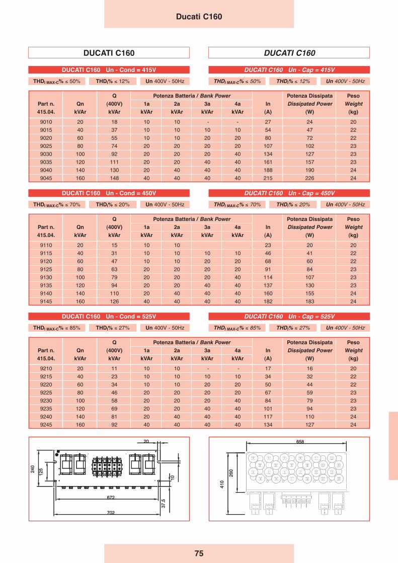
75
Q Potenza Batteria / Bank Power Potenza Dissipata Peso
Part n. Qn (400V) 1a 2a 3a 4a In Dissipated Power Weight
415.04. kVAr kVAr kVAr kVAr kVAr kVAr (A) (W) (kg)
9010 20 18 10 10 - - 27 24 20
9015 40 37 10 10 10 10 54 47 22
9020 60 55 10 10 20 20 80 72 22
9025 80 74 20 20 20 20 107 102 23
9030 100 92 20 20 20 40 134 127 23
9035 120 111 20 20 40 40 161 157 23
9040 140 130 20 40 40 40 188 190 24
9045 160 148 40 40 40 40 215 226 24
Q Potenza Batteria / Bank Power Potenza Dissipata Peso
Part n. Qn (400V) 1a 2a 3a 4a In Dissipated Power Weight
415.04. kVAr kVAr kVAr kVAr kVAr kVAr (A) (W) (kg)
9110 20 15 10 10 23 20 20
9115 40 31 10 10 10 10 46 41 22
9120 60 47 10 10 20 20 68 60 22
9125 80 63 20 20 20 20 91 84 23
9130 100 79 20 20 20 40 114 107 23
9135 120 94 20 20 40 40 137 130 23
9140 140 110 20 40 40 40 160 155 24
9145 160 126 40 40 40 40 182 183 24
Q Potenza Batteria / Bank Power Potenza Dissipata Peso
Part n. Qn (400V) 1a 2a 3a 4a In Dissipated Power Weight
415.04. kVAr kVAr kVAr kVAr kVAr kVAr (A) (W) (kg)
9210 20 11 10 10 - - 17 16 20
9215 40 23 10 10 10 10 34 32 22
9220 60 34 10 10 20 20 50 44 22
9225 80 46 20 20 20 20 67 59 23
9230 100 58 20 20 20 40 84 79 23
9235 120 69 20 20 40 40 101 94 23
9240 140 81 20 40 40 40 117 110 24
9245 160 92 40 40 40 40 134 127 24
DUCATI C160 DUCATI C160
Ducati C160
DUCATI C160 Un - Cap = 415V
THDI MAX-C% ≤ 50% THDI% ≤ 12% Un 400V - 50Hz
DUCATI C160 Un - Cap = 450V
THDI MAX-C% ≤ 70% THDI% ≤ 20% Un 400V - 50Hz
DUCATI C160 Un - Cond = 415V
THDI MAX-C% ≤ 50% THDI% ≤ 12% Un 400V - 50Hz
DUCATI C160 Un - Cond = 450V
THDI MAX-C% ≤ 70% THDI% ≤ 20% Un 400V - 50Hz
DUCATI C160 Un - Cap = 525V
THDI MAX-C% ≤ 85% THDI% ≤ 27% Un 400V - 50Hz
DUCATI C160 Un - Cond = 525V
THDI MAX-C% ≤ 85% THDI% ≤ 27% Un 400V - 50Hz
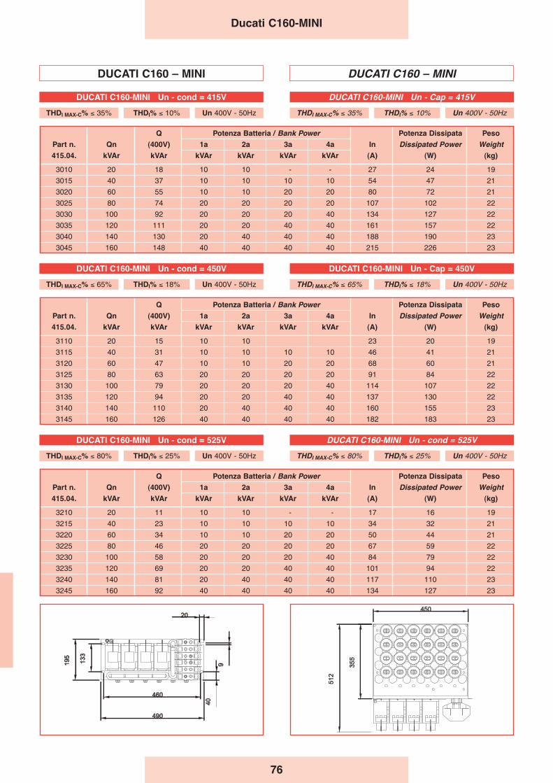
76
Q Potenza Batteria / Bank Power Potenza Dissipata Peso
Part n. Qn (400V) 1a 2a 3a 4a In Dissipated Power Weight
415.04. kVAr kVAr kVAr kVAr kVAr kVAr (A) (W) (kg)
3010 20 18 10 10 - - 27 24 19
3015 40 37 10 10 10 10 54 47 21
3020 60 55 10 10 20 20 80 72 21
3025 80 74 20 20 20 20 107 102 22
3030 100 92 20 20 20 40 134 127 22
3035 120 111 20 20 40 40 161 157 22
3040 140 130 20 40 40 40 188 190 23
3045 160 148 40 40 40 40 215 226 23
Q Potenza Batteria / Bank Power Potenza Dissipata Peso
Part n. Qn (400V) 1a 2a 3a 4a In Dissipated Power Weight
415.04. kVAr kVAr kVAr kVAr kVAr kVAr (A) (W) (kg)
3110 20 15 10 10 23 20 19
3115 40 31 10 10 10 10 46 41 21
3120 60 47 10 10 20 20 68 60 21
3125 80 63 20 20 20 20 91 84 22
3130 100 79 20 20 20 40 114 107 22
3135 120 94 20 20 40 40 137 130 22
3140 140 110 20 40 40 40 160 155 23
3145 160 126 40 40 40 40 182 183 23
Q Potenza Batteria / Bank Power Potenza Dissipata Peso
Part n. Qn (400V) 1a 2a 3a 4a In Dissipated Power Weight
415.04. kVAr kVAr kVAr kVAr kVAr kVAr (A) (W) (kg)
3210 20 11 10 10 - - 17 16 19
3215 40 23 10 10 10 10 34 32 21
3220 60 34 10 10 20 20 50 44 21
3225 80 46 20 20 20 20 67 59 22
3230 100 58 20 20 20 40 84 79 22
3235 120 69 20 20 40 40 101 94 22
3240 140 81 20 40 40 40 117 110 23
3245 160 92 40 40 40 40 134 127 23
DUCATI C160 – MINI DUCATI C160 – MINI
Ducati C160-MINI
DUCATI C160-MINI Un - cond = 415V
THDI MAX-C% ≤ 35% THDI% ≤ 10% Un 400V - 50Hz
DUCATI C160-MINI Un - Cap = 415V
THDI MAX-C% ≤ 35% THDI% ≤ 10% Un 400V - 50Hz
DUCATI C160-MINI Un - cond = 450V
THDI MAX-C% ≤ 65% THDI% ≤ 18% Un 400V - 50Hz
DUCATI C160-MINI Un - Cap = 450V
THDI MAX-C% ≤ 65% THDI% ≤ 18% Un 400V - 50Hz
DUCATI C160-MINI Un - cond = 525V
THDI MAX-C% ≤ 80% THDI% ≤ 25% Un 400V - 50Hz
DUCATI C160-MINI Un - cond = 525V
THDI MAX-C% ≤ 80% THDI% ≤ 25% Un 400V - 50Hz
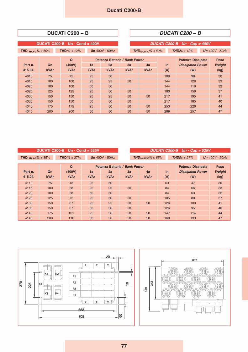
77
DUCATI C200 – B DUCATI C200 – B
Q Potenza Batteria / Bank Power Potenza Dissipata Peso
Part n. Qn (400V) 1a 2a 3a 4a In Dissipated Power Weight
415.04. kVAr kVAr kVAr kVAr kVAr kVAr (A) (W) (kg)
4010 75 75 25 50 108 98 30
4015 100 100 25 25 50 144 128 33
4020 100 100 50 50 144 119 32
4025 125 125 25 50 50 180 159 37
4030 150 150 25 25 50 50 217 195 41
4035 150 150 50 50 50 217 185 40
4040 175 175 25 50 50 50 253 226 44
4045 200 200 50 50 50 50 289 257 47
Q Potenza Batteria / Bank Power Potenza Dissipata Peso
Part n. Qn (400V) 1a 2a 3a 4a In Dissipated Power Weight
415.04. kVAr kVAr kVAr kVAr kVAr kVAr (A) (W) (kg)
4110 75 43 25 50 63 47 30
4115 100 58 25 25 50 84 66 33
4120 100 58 50 50 84 63 32
4125 125 72 25 50 50 105 80 37
4130 150 87 25 25 50 50 126 100 41
4135 150 87 50 50 50 126 95 40
4140 175 101 25 50 50 50 147 114 44
4145 200 116 50 50 50 50 168 133 47
Ducati C200-B
DUCATI C200-B Un - Cap = 400V
THDI MAX-C% ≤ 50% THDI% ≤ 12% Un 400V - 50Hz
DUCATI C200-B Un - Cond = 400V
THDI MAX-C% ≤ 50% THDI% ≤ 12% Un 400V - 50Hz
DUCATI C200-B Un - Cap = 525V
THDI MAX-C% ≤ 85% THDI% ≤ 27% Un 400V - 50Hz
DUCATI C200-B Un - Cond = 525V
THDI MAX-C% ≤ 85% THDI% ≤ 27% Un 400V - 50Hz
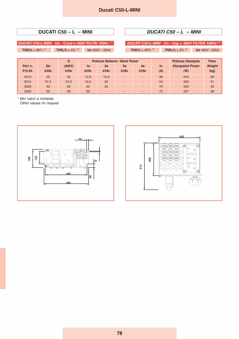
78
DUCATI C50 – L – MINI DUCATI C50 – L – MINI
Q Potenza Batteria / Bank Power Potenza Dissipata Peso
Part n. Qn (400V) 1a 2a 3a 4a In Dissipated Power Weight
415.04. kVAr kVAr kVAr kVAr kVAr kVAr (A) (W) (kg)
3310 25 25 12,5 12,5 - - 36 244 29
3315 37,5 37,5 12,5 25 - - 54 293 31
3320 50 50 25 25 - - 72 342 43
3325 50 50 50 - - - 72 337 38
Ducati C50-L-MINI
DUCATI C50-L-MINI Un - Cap = 480V FILTER 189Hz (*)
THDI% ≤ 80% (*) THDV% ≤ 6% (*) Un 400V - 50Hz
DUCATI C50-L-MINI Un - Cond = 480V FILTRI 189Hz (*)
THDI% ≤ 80% (*) THDV% ≤ 6% (*) Un 400V - 50Hz
* Altri valori a richiestaOther values on request
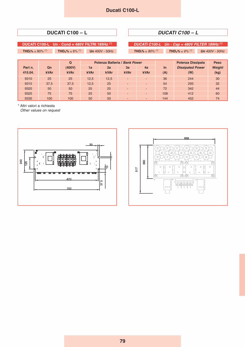
79
DUCATI C100 – L DUCATI C100 – L
Q Potenza Batteria / Bank Power Potenza Dissipata Peso
Part n. Qn (400V) 1a 2a 3a 4a In Dissipated Power Weight
415.04. kVAr kVAr kVAr kVAr kVAr kVAr (A) (W) (kg)
9310 25 25 12,5 12,5 - - 36 244 30
9315 37,5 37,5 12,5 25 - - 54 293 32
9320 50 50 25 25 - - 72 342 44
9325 75 75 25 50 - - 108 412 60
9330 100 100 50 50 - - 144 452 74
Ducati C100-L
DUCATI C100-L Un - Cap = 480V FILTER 189Hz (*)
THDI% ≤ 80% (*) THDV% ≤ 6% (*) Un 400V - 50Hz
DUCATI C100-L Un - Cond = 480V FILTRI 189Hz (*)
THDI% ≤ 80% (*) THDV% ≤ 6% (*) Un 400V - 50Hz
* Altri valori a richiestaOther values on request

80
DUCATI C100 – LB DUCATI C100 – LB
Q Potenza Batteria / Bank Power Potenza Dissipata Peso
Part n. Qn (400V) 1a 2a 3a 4a In Dissipated Power Weight
415.04. kVAr kVAr kVAr kVAr kVAr kVAr (A) (W) (kg)
4210 25 25 12,5 12,5 36 243 65
4215 37,5 37,5 12,5 25 54 293 70
4220 50 50 25 25 72 341 75
4225 62,5 62,5 12,5 50 90 352 85
4230 75 75 25 50 108 411 90
4235 100 100 50 50 144 451 100
Ducati C100-LB
DUCATI C100-LB Un - Cap = 480V FILTER 189Hz (*)
THDI% ≤ 80% (*) THDV% ≤ 6% (*) Un 400V - 50Hz
DUCATI C100-LB Un - Cond = 480V FILTRO 189Hz (*)
THDI% ≤ 80% (*) THDV% ≤ 6% (*) Un 400V - 50Hz
* Altri valori a richiestaOther values on request
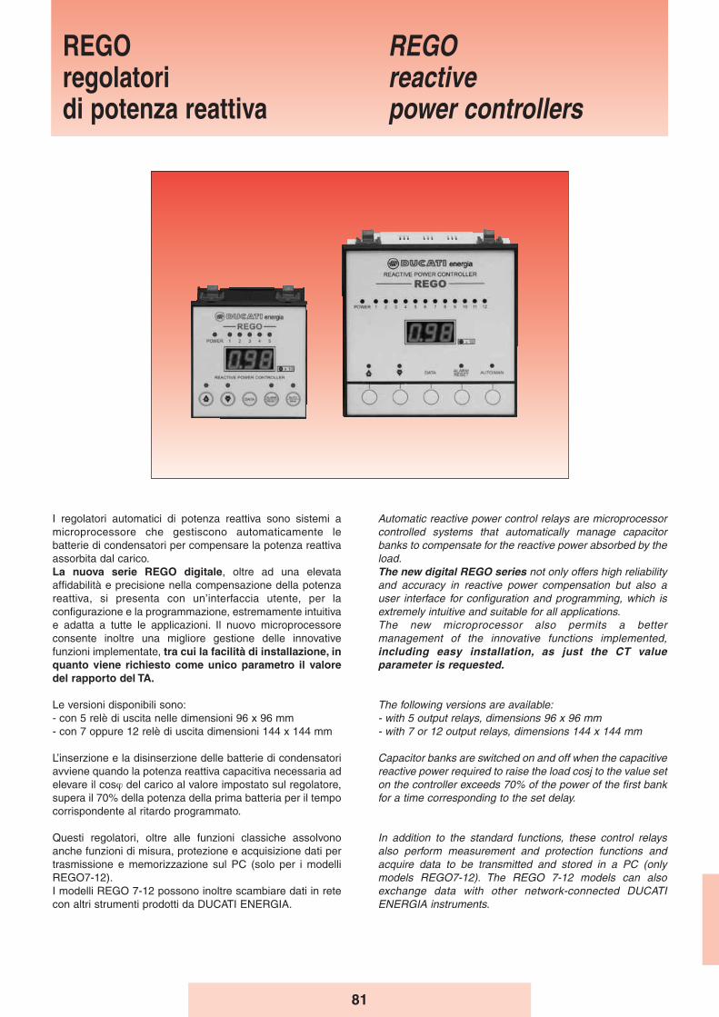
81
I regolatori automatici di potenza reattiva sono sistemi amicroprocessore che gestiscono automaticamente lebatterie di condensatori per compensare la potenza reattivaassorbita dal carico.La nuova serie REGO digitale, oltre ad una elevataaffidabilità e precisione nella compensazione della potenzareattiva, si presenta con un’interfaccia utente, per laconfigurazione e la programmazione, estremamente intuitivae adatta a tutte le applicazioni. Il nuovo microprocessoreconsente inoltre una migliore gestione delle innovativefunzioni implementate, tra cui la facilità di installazione, inquanto viene richiesto come unico parametro il valoredel rapporto del TA.
Le versioni disponibili sono:- con 5 relè di uscita nelle dimensioni 96 x 96 mm- con 7 oppure 12 relè di uscita dimensioni 144 x 144 mm
L’inserzione e la disinserzione delle batterie di condensatoriavviene quando la potenza reattiva capacitiva necessaria adelevare il cosϕ del carico al valore impostato sul regolatore,supera il 70% della potenza della prima batteria per il tempocorrispondente al ritardo programmato.
Questi regolatori, oltre alle funzioni classiche assolvonoanche funzioni di misura, protezione e acquisizione dati pertrasmissione e memorizzazione sul PC (solo per i modelliREGO7-12).I modelli REGO 7-12 possono inoltre scambiare dati in retecon altri strumenti prodotti da DUCATI ENERGIA.
Automatic reactive power control relays are microprocessorcontrolled systems that automatically manage capacitorbanks to compensate for the reactive power absorbed by theload.The new digital REGO series not only offers high reliabilityand accuracy in reactive power compensation but also auser interface for configuration and programming, which isextremely intuitive and suitable for all applications.The new microprocessor also permits a bettermanagement of the innovative functions implemented,including easy installation, as just the CT valueparameter is requested.
The following versions are available:- with 5 output relays, dimensions 96 x 96 mm- with 7 or 12 output relays, dimensions 144 x 144 mm
Capacitor banks are switched on and off when the capacitivereactive power required to raise the load cosj to the value seton the controller exceeds 70% of the power of the first bankfor a time corresponding to the set delay.
In addition to the standard functions, these control relaysalso perform measurement and protection functions andacquire data to be transmitted and stored in a PC (onlymodels REGO7-12). The REGO 7-12 models can alsoexchange data with other network-connected DUCATIENERGIA instruments.
REGOregolatori di potenza reattiva
REGOreactivepower controllers
82
Le caratteristiche più innovative del REGO sono:- Unico parametro da impostare in fase di installazione:
rapporto del TA (esempio 1000/5 : impostare 200).- Verso di corrente del TA automaticamente adattato ai
riferimenti interni del regolatore.- Regolazione lineare del cosϕ da 0,8 induttivo a 0,8
capacitivo.- Regolazione automatica C/k.- Comando Manuale delle batterie in totale indipendenza
della misura effettuata in linea.- Inibizione dei relè di uscita non impiegati.- Impostazione per rifasamento di generatori asincroni.- Impostazione dei tempi di intervento da 0,5 a 300 sec.
Impostazione del tempo di scarica da 5 a 255 sec.
- Nr. 3 logiche di inserzione/disinserzione batterie, conriconoscimento automatico:
- Logica Universale Geometrica (1:2:4), permette di ottenereun numero elevato di gradini minimizzando il numero dibatterie;
- Logica Lineare Circolare (1:1:1), utilizzabile quando lebatterie sono tutte uguali, il comando dei relè di uscitaavviene con sequenza circolare, ottenendo unadistribuzione più uniforme delle manovre sui contattori;
- Logica Lineare Semicircolare (1:2:2), intermedie fra leprecedenti consente di ottenere un numero di gradini piùelevato rispetto alla logica (1:1:1).
I modelli REGO tramite il display sul frontale visualizza-no:- Cosϕ di linea;- Corrente di linea;- Tensione di rete;- Potenza attiva in linea;- Potenza reattiva in linea;- Distorsione della corrente del TA (THDI);- n. di manovre effettuate da ogni contattore;- n. di interventi degli allarmi;- Potenze dei singoli gradini;- Temperatura interna quadro nella zona vicina al
regolatore.
Il SISTEMA DI PROTEZIONE a salvaguardia delrifasamento comprende:- Allarme da sovratensione, attiva anche quando nessuna
batteria è inserita, protegge il regolatore da sovratensionimaggiori di quelle ammesse, di durata superiore ai 30secondi;
- Protezione da sovratemperatura, attiva anche quandonessuna batteria è inserita, interviene quando latemperatura in prossimità del regolatore supera il limiteimpostato per almeno 15 secondi;
- Protezione da sovraccarico armonico, protegge icondensatori da sovraccarico armonico eccessivo;
- Allarme per mancato rifasamento, segnala che il cosϕ èstato inferiore a quello impostato per un tempo maggiore didue ore con tutte le batterie inserite;
- Protezione da mancanza di tensione, diseccita i relèquando la tensione manca per più di due periodi. Al suoritorno il regolatore riprenderà a funzionare sotto il controlloautomatico.
A meno dell’ultima protezione, l’intervento delle protezionipuò essere riportato a distanza per mezzo di un contattopulito. Tutte le protezioni (tranne l'ultima) sono di defaultautoripristinabili (il regolatore riprende il funzionamentodopo 30 minuti di standby in condizione di allarme), epossono essere eventualmente inibite.
The most innovative features of REGO are:- Sole parameter to be set up during installation: CT
ratio (i.e 1000/5 : set 200).- CT circulation direction is automatically adjusted to control
relay internal data.- Cosϕ linear setting from 0.8 IND to 0.8 CAP.- C/k automatic setting.- Banks manual control, regardless of the line value
measured. - Inhibition of the unused output relays.- Setting for power factor correction of asynchronous
generators.- Operating time setting from 0.5 to 300 sec.
Discharge time setting from 5 to 255 sec.
- 3 logics to connect/disconnect banks, with automaticdetection:
- Universal geometric logic (1:2:4), in which it is possible toobtain a high number of steps, while minimising thenumber of banks;
- Circular and linear logic (1:1:1), in which the output relaysare controlled in a circular sequence, thus allowing a moreeven distribution of operations on contacts andconsiderably reducing maintenance required;
- Semicircular and linear logic (1:2:2), in which it is possibleto obtain a higher number of steps than the logic (1:1:1).
The REGO family shows on its front display:- Line Cosϕ;- Line current;- Mains voltage;- Line active power;- Line reactive power;- CT current crest factor (THDI);- Counter of operations performed by each output relay;- Number of alarm conditions;- Powers of individual steps;- Internal panel inside temperature, in the area around
the power control relay.
The PROTECTION SYSTEM of the power factor correctionsystem includes:- Overvoltage alarm activated even when no capacitor bank
is switched on; it protects the control relay from more than30 seconds’ exposure to overvoltages exceeding theallowed limit;
- Overtemperature protection which is active even whenno capacitor bank is switched on; it is tripped when the airtemperature around the control relay exceeds the set limitfor at least 15 seconds;
- Harmonic overload protection, which protects thecapacitors from excessive harmonic overloads;
- Power factor correction fault alarm, which signals thatthe cosϕ has remained below the set value for more thantwo hours with all banks switched on;
- No voltage protection, which cuts out relays when thereis no voltage for more than two periods. When power isrestored, the controller will resume operation underautomatic control.
All protections with the exception of the latter can beremotely controlled through a clean contact.All protections (except the last one) are default self-resettable (the controller will start again after 30 minutes’ standby in a status of alert), and can beinhibited.
REGO
83
Part n. Tipo Sequenza Tensione Frequency Tempo intervento
415.98. Type Sequence Voltage Frequency switching timeV Hz sec.
1:1:1
.5040 REGO 5 1:2:2 220/240-380/415 50/60 0.5÷300”
1:2:4
1:1:1
.7040 REGO 7 1:2:2 220/240-380/415 50/60 0.5÷300”
1:2:4
1:1:1
.9040 REGO 12 1:2:2 220/240-380/415 50/60 0.5÷300”
1:2:4
I modelli REGO 7-12 hanno una porta RS-485 ed utilizzanoil protocollo di comunicazione “Duc Bus”.
INDICAZIONI LUMINOSE sono presenti sul fronte deiregolatori per segnalare:- Presenza tensione;- Batterie inserite;- Necessità di inserimento/disinserimento condensatori;- LED allarme;- Impostazione funzionamento manuale.Le grandezze misurate e l’intervento delle protezioni sonosegnalate dal display.
CARATTERISTICHE GENERALI
Tensione di ingresso: 220/240V - 380/415VTolleranza della tensione di ingresso: ± 10%Frequenza: 50/60 HzPotenza assorbita
REGO 7-12: 15 VA maxREGO 5: 6 VA max
Alimentazione amperometrica (TA): …/5AConsumo amperometrico REGO 7-12: 0,5 VA max
REGO 5: 0,25 VA maxPortata relè di uscita: 1500 VA - 250 VacPortata transistor di uscita: 30mA-24VPortata relè allarme remoto: NC (6 A - 250 Vac)Temperatura ambiente di funzionamento: – 40/+60°CGrado di protezione frontale: IP 40Terminali REGO 7-12: morsetti a molla 2,5 mm2
REGO 5: morsetti a vite estraibile 2,5 mm2
Dimensioni (mm) REGO 5: 96 x 96 x 65 mm.REGO 7-12: 144 x 144 x 60 mm.
Foratura REGO 5: 91 x 89 mm.REGO 7-12: 138 x 138 mm.
Custodia: materiale plastico autoestinguenteFissaggio: con 4 setti di pressioneCollegamento con PC solo REGO 7-12: porta seriale RS 485Peso REGO5: 0.735 kg
REGO7: 0.795 kgREGO12: 0.875 kg
Norme: EN 61010 - 1EN 50081 - 1EN 50082 - 2
Caratteristiche Tecniche e Costruttive
REGO 7-12 versions have an RS-485 serial port and use“DUC BUS” protocol.
DISPLAY LIGHTS on control relays indicate: - Voltage;- Banks on;- Capacitors connection/disconnection required;- Alarm LED.- Setting manual.Measurements and tripped protections are shown on thedisplay.
GENERAL CHARACTERISTICS
Voltage input : 220/240V - 380/415VVoltage tolerance : ± 10%Frequency : 50/60 HzVoltage consumption
REGO 7-12: 15 VA maxREGO 5 : 6 VA max
Current input (by C.T.) : …/5ACurrent consumption REGO 7-12 : 0,5 VA max
REGO 5 : 0,25 VA maxSwitching contacts : 1500 VA - 250 VacSwitching transistor : 30mA-24VContact for remote alarm indication : NC (6 A - 250 Vac)Ambient temperature range : – 40/+60°CFront protection degree : IP 40Connection REGO 7-12: spring terminal blocks 2,5 mm2
REGO 5 : extractible screw connectors 2,5 mm2
Dimensions (mm) REGO 5 : 96 x 96 x 65 mm.REGO 7-12: 144 x 144 x 60 mm.
Drilling REGO 5 : 91 x 89 mm.REGO 7-12: 138 x 138 mm.
Casing : plastic material autoextinguishingFixing : by means of 4 pressure bufflesPC connection REGO 7-12: RS 485 serial portweight: REGO 5: 0,735 Kg
REGO 7: 0,795 KgREGO 12: 0,875 Kg
Standards : EN 61010 - 1EN 50081 - 1EN 50082 - 2
Technical and manufacturing characteristics
REGO
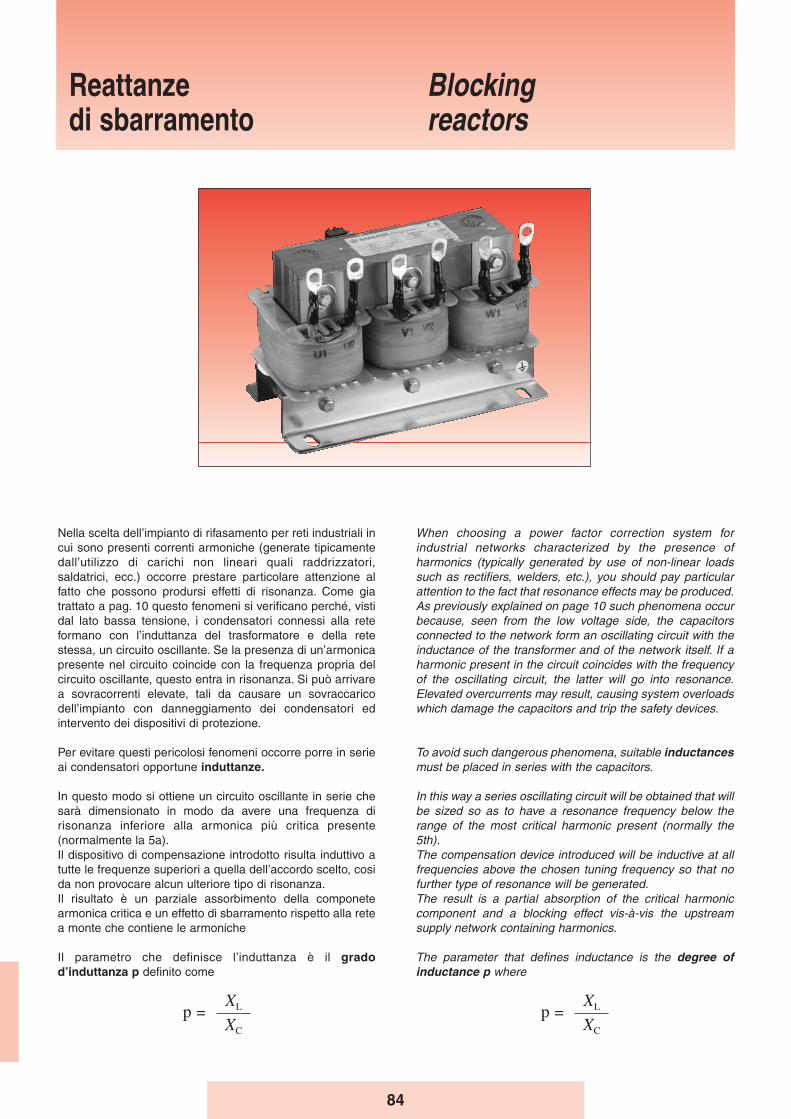
84
Reattanze di sbarramento
Blocking reactors
Nella scelta dell’impianto di rifasamento per reti industriali incui sono presenti correnti armoniche (generate tipicamentedall’utilizzo di carichi non lineari quali raddrizzatori,saldatrici, ecc.) occorre prestare particolare attenzione alfatto che possono prodursi effetti di risonanza. Come giatrattato a pag. 10 questo fenomeni si verificano perché, vistidal lato bassa tensione, i condensatori connessi alla reteformano con l’induttanza del trasformatore e della retestessa, un circuito oscillante. Se la presenza di un’armonicapresente nel circuito coincide con la frequenza propria delcircuito oscillante, questo entra in risonanza. Si può arrivarea sovracorrenti elevate, tali da causare un sovraccaricodell’impianto con danneggiamento dei condensatori edintervento dei dispositivi di protezione.
Per evitare questi pericolosi fenomeni occorre porre in serieai condensatori opportune induttanze.
In questo modo si ottiene un circuito oscillante in serie chesarà dimensionato in modo da avere una frequenza dirisonanza inferiore alla armonica più critica presente(normalmente la 5a).Il dispositivo di compensazione introdotto risulta induttivo atutte le frequenze superiori a quella dell’accordo scelto, cosida non provocare alcun ulteriore tipo di risonanza.Il risultato è un parziale assorbimento della componetearmonica critica e un effetto di sbarramento rispetto alla retea monte che contiene le armoniche
Il parametro che definisce l’induttanza è il gradodʼinduttanza p definito come
When choosing a power factor correction system forindustrial networks characterized by the presence ofharmonics (typically generated by use of non-linear loadssuch as rectifiers, welders, etc.), you should pay particularattention to the fact that resonance effects may be produced.As previously explained on page 10 such phenomena occurbecause, seen from the low voltage side, the capacitorsconnected to the network form an oscillating circuit with theinductance of the transformer and of the network itself. If aharmonic present in the circuit coincides with the frequencyof the oscillating circuit, the latter will go into resonance.Elevated overcurrents may result, causing system overloadswhich damage the capacitors and trip the safety devices.
To avoid such dangerous phenomena, suitable inductancesmust be placed in series with the capacitors.
In this way a series oscillating circuit will be obtained that willbe sized so as to have a resonance frequency below therange of the most critical harmonic present (normally the5th).The compensation device introduced will be inductive at allfrequencies above the chosen tuning frequency so that nofurther type of resonance will be generated.The result is a partial absorption of the critical harmoniccomponent and a blocking effect vis-à-vis the upstreamsupply network containing harmonics.
The parameter that defines inductance is the degree ofinductance p where
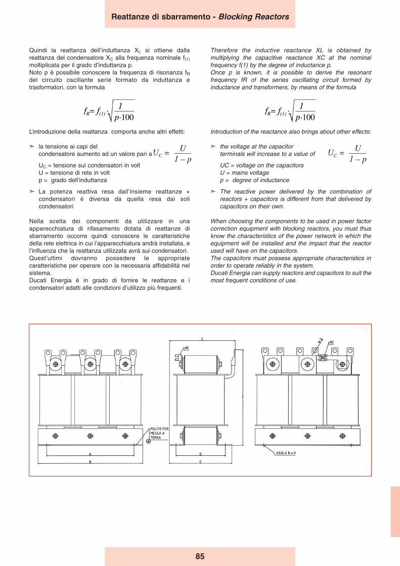
85
Quindi la reattanza dell’induttanza XL si ottiene dallareattanza del condensatore XC alla frequenza nominale f(1)
moltiplicata per il grado d’induttanza p.Noto p è possibile conoscere la frequenza di risonanza fRdel circuito oscillante serie formato da induttanza etrasformatori, con la formula
L’introduzione della reattanza comporta anche altri effetti:
➣ la tensione ai capi del condensatore aumento ad un valore pari a
UC = tensione sui condensatori in voltU = tensione di rete in voltp = grado dell’induttanza
➣ La potenza reattiva resa dall’insieme reattanze +condensatori è diversa da quella resa dai solicondensatori
Nella scelta dei componenti da utilizzare in unaapparecchiatura di rifasamento dotata di reattanze disbarramento occorre quindi conoscere le caratteristichedella rete elettrica in cui l’apparecchiatura andrà installata, el’influenza che la reattanza utilizzata avrà sui condensatori.Quest’ultimi dovranno possedere le appropriatecaratteristiche per operare con la necessaria affidabilità nelsistema.Ducati Energia è in grado di fornire le reattanze e icondensatori adatti alle condizioni d’utilizzo più frequenti.
Therefore the inductive reactance XL is obtained bymultiplying the capacitive reactance XC at the nominalfrequency f(1) by the degree of inductance p.Once p is known, it is possible to derive the resonantfrequency fR of the series oscillating circuit formed byinductance and transformers, by means of the formula
Introduction of the reactance also brings about other effects:
➣ the voltage at the capacitor terminals will increase to a value of
UC = voltage on the capacitorsU = mains voltagep = degree of inductance
➣ The reactive power delivered by the combination ofreactors + capacitors is different from that delivered bycapacitors on their own.
When choosing the components to be used in power factorcorrection equipment with blocking reactors, you must thusknow the characteristics of the power network in which theequipment will be installed and the impact that the reactorused will have on the capacitors.The capacitors must possess appropriate characteristics inorder to operate reliably in the system.Ducati Energia can supply reactors and capacitors to suit themost frequent conditions of use.
1fR= f(1).
p%
Reattanze di sbarramento - Blocking Reactors
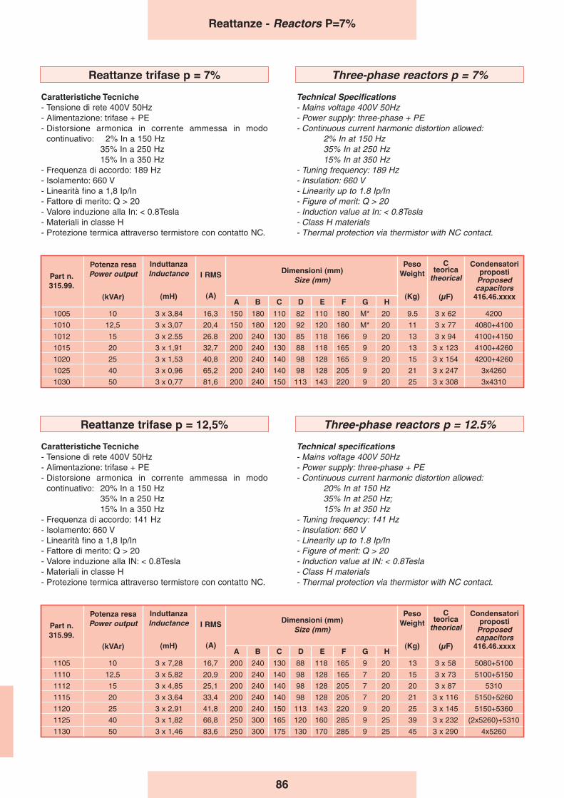
86
1005 10 3 x 3,84 16,3 150 180 110 82 110 180 M* 20 9.5 3 x 62 4200
1010 12,5 3 x 3,07 20,4 150 180 120 92 120 180 M* 20 11 3 x 77 4080+4100
1012 15 3 x 2.55 26.8 200 240 130 85 118 166 9 20 13 3 x 94 4100+4150
1015 20 3 x 1,91 32,7 200 240 130 88 118 165 9 20 13 3 x 123 4100+4260
1020 25 3 x 1,53 40,8 200 240 140 98 128 165 9 20 15 3 x 154 4200+4260
1025 40 3 x 0,96 65,2 200 240 140 98 128 205 9 20 21 3 x 247 3x4260
1030 50 3 x 0,77 81,6 200 240 150 113 143 220 9 20 25 3 x 308 3x4310
A B C D E F G H
PesoWeight
(Kg)
Part n.315.99.
Potenza resaPower output
(kVAr)
InduttanzaInductance
(mH)
I RMS
(A)
Dimensioni (mm)Size (mm)
C teorica
theorical
(μF)
Condensatoriproposti
Proposedcapacitors
416.46.xxxx
Reattanze trifase p = 7%
Caratteristiche Tecniche- Tensione di rete 400V 50Hz- Alimentazione: trifase + PE- Distorsione armonica in corrente ammessa in modo
continuativo: 2% In a 150 Hz35% In a 250 Hz15% In a 350 Hz
- Frequenza di accordo: 189 Hz- Isolamento: 660 V- Linearità fino a 1,8 Ip/In- Fattore di merito: Q > 20- Valore induzione alla In: < 0.8Tesla- Materiali in classe H- Protezione termica attraverso termistore con contatto NC.
Three-phase reactors p = 7%
Technical Specifications- Mains voltage 400V 50Hz- Power supply: three-phase + PE- Continuous current harmonic distortion allowed:
2% In at 150 Hz35% In at 250 Hz15% In at 350 Hz
- Tuning frequency: 189 Hz- Insulation: 660 V- Linearity up to 1.8 Ip/In- Figure of merit: Q > 20- Induction value at In: < 0.8Tesla- Class H materials- Thermal protection via thermistor with NC contact.
Reattanze - Reactors P=7%
Reattanze trifase p = 12,5%
Caratteristiche Tecniche- Tensione di rete 400V 50Hz- Alimentazione: trifase + PE- Distorsione armonica in corrente ammessa in modo
continuativo: 20% In a 150 Hz35% In a 250 Hz15% In a 350 Hz
- Frequenza di accordo: 141 Hz- Isolamento: 660 V- Linearità fino a 1,8 Ip/In- Fattore di merito: Q > 20- Valore induzione alla IN: < 0.8Tesla- Materiali in classe H- Protezione termica attraverso termistore con contatto NC.
Three-phase reactors p = 12.5%
Technical specifications- Mains voltage 400V 50Hz- Power supply: three-phase + PE- Continuous current harmonic distortion allowed:
20% In at 150 Hz35% In at 250 Hz;15% In at 350 Hz
- Tuning frequency: 141 Hz- Insulation: 660 V- Linearity up to 1.8 Ip/In- Figure of merit: Q > 20- Induction value at IN: < 0.8Tesla- Class H materials- Thermal protection via thermistor with NC contact.
1105 10 3 x 7,28 16,7 200 240 130 88 118 165 9 20 13 3 x 58 5080+5100
1110 12,5 3 x 5,82 20,9 200 240 140 98 128 165 7 20 15 3 x 73 5100+5150
1112 15 3 x 4,85 25,1 200 240 140 98 128 205 7 20 20 3 x 87 5310
1115 20 3 x 3,64 33,4 200 240 140 98 128 205 7 20 21 3 x 116 5150+5260
1120 25 3 x 2,91 41,8 200 240 150 113 143 220 9 20 25 3 x 145 5150+5360
1125 40 3 x 1,82 66,8 250 300 165 120 160 285 9 25 39 3 x 232 (2x5260)+5310
1130 50 3 x 1,46 83,6 250 300 175 130 170 285 9 25 45 3 x 290 4x5260
A B C D E F G H
PesoWeight
(Kg)
Part n.315.99.
Potenza resaPower output
(kVAr)
InduttanzaInductance
(mH)
I RMS
(A)
Dimensioni (mm)Size (mm)
C teorica
theorical
(μF)
Condensatoriproposti
Proposedcapacitors
416.46.xxxx
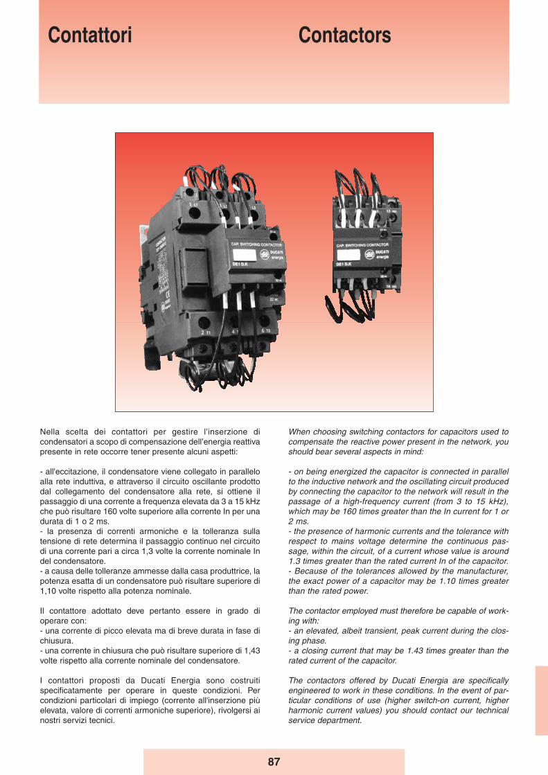
87
Nella scelta dei contattori per gestire l’inserzione dicondensatori a scopo di compensazione dell’energia reattivapresente in rete occorre tener presente alcuni aspetti:
- all'eccitazione, il condensatore viene collegato in paralleloalla rete induttiva, e attraverso il circuito oscillante prodottodal collegamento del condensatore alla rete, si ottiene ilpassaggio di una corrente a frequenza elevata da 3 a 15 kHzche può risultare 160 volte superiore alla corrente In per unadurata di 1 o 2 ms. - la presenza di correnti armoniche e la tolleranza sullatensione di rete determina il passaggio continuo nel circuitodi una corrente pari a circa 1,3 volte la corrente nominale Indel condensatore.- a causa delle tolleranze ammesse dalla casa produttrice, lapotenza esatta di un condensatore può risultare superiore di1,10 volte rispetto alla potenza nominale.
Il contattore adottato deve pertanto essere in grado dioperare con:- una corrente di picco elevata ma di breve durata in fase dichiusura. - una corrente in chiusura che può risultare superiore di 1,43volte rispetto alla corrente nominale del condensatore.
I contattori proposti da Ducati Energia sono costruitispecificatamente per operare in queste condizioni. Percondizioni particolari di impiego (corrente all'inserzione piùelevata, valore di correnti armoniche superiore), rivolgersi ainostri servizi tecnici.
When choosing switching contactors for capacitors used tocompensate the reactive power present in the network, youshould bear several aspects in mind:
- on being energized the capacitor is connected in parallelto the inductive network and the oscillating circuit producedby connecting the capacitor to the network will result in thepassage of a high-frequency current (from 3 to 15 kHz),which may be 160 times greater than the In current for 1 or2 ms. - the presence of harmonic currents and the tolerance withrespect to mains voltage determine the continuous pas-sage, within the circuit, of a current whose value is around1.3 times greater than the rated current In of the capacitor.- Because of the tolerances allowed by the manufacturer,the exact power of a capacitor may be 1.10 times greaterthan the rated power.
The contactor employed must therefore be capable of work-ing with:- an elevated, albeit transient, peak current during the clos-ing phase. - a closing current that may be 1.43 times greater than therated current of the capacitor.
The contactors offered by Ducati Energia are specificallyengineered to work in these conditions. In the event of par-ticular conditions of use (higher switch-on current, higherharmonic current values) you should contact our technicalservice department.
Contattori Contactors
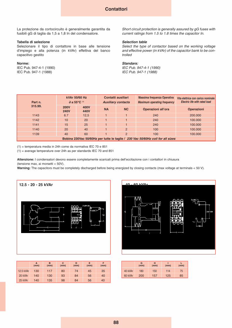
88
La protezione da cortocircuito è generalmente garantita dafusibili gG di taglia da 1,5 a 1,8 In del condensatore.
Tabella di selezioneSelezionare il tipo di contattore in base alle tensioned’impiego e alla potenza (in kVAr) effettiva del bancocapacitivo gestito
Norme:IEC Pub. 947-4-1 (1990)IEC Pub. 947-1 (1988)
Short circuit protection is generally assured by gG fuses withcurrent ratings from 1.5 to 1.8 times the capacitor In.
Selection tableSelect the type of contactor based on the working voltageand effective power (in kVAr) of the capacitor bank to be con-trolled
Standars:IEC Pub. 947-4-1 (1990)IEC Pub. 947-1 (1988)
Contattori
1143 6.7 12,5 1 1 240 200.000
1142 10 20 1 1 240 100.000
1141 15 25 1 1 240 100.000
1140 20 40 1 2 100 100.000
1139 40 60 1 2 100 100.000
Bobina 230Vac 50/60Hz per tutte le taglie / 230 Vac 50/60Hz coil for all sizes
kVAr 50/60 Hz
∂ ≤ 55°C (1)
200V240V
400V440V
NA NC Operazioni allʼora Operazioni
Part n.315.99.
Contatti ausiliari
Auxiliary contactsMassima frequenza Operativa
Maximum operating frequencyVita elettrica con carico nominale
Electric life with rated load
(1) = temperatura media in 24h come da normativa IEC 70 e 851(1) = average temperature over 24h as per standards IEC 70 and 851
Attenzione: I condensatori devono essere completamente scaricati prima dell’eccitazione con i contattori in chiusura (tensione max, ai morsetti < 50V).Warning: The capacitors must be completely discharged before being energized by closing contacts (max voltage at terminals < 50 V).
12.5 - 20 - 25 kVAr 40 - 60 kVAr
A(mm)
B(mm)
C(mm)
D(mm)
E(mm)
F(mm)
12.5 kVAr 130 117 80 74 45 35
20 kVAr 140 130 93 84 56 40
25 kVAr 140 135 98 84 56 40
G(mm)
H(mm)
I(mm)
L(mm)
40 kVAr 180 150 114 75
60 kVAr 200 157 125 85
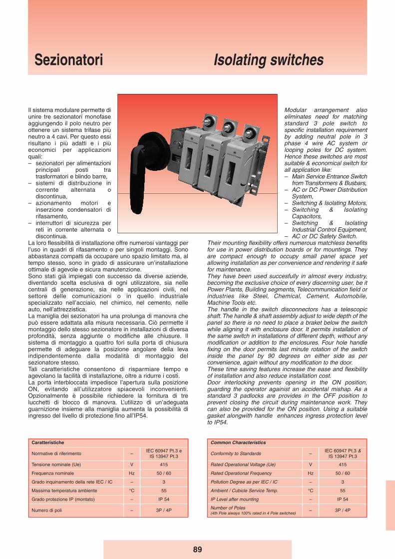
89
Sezionatori Isolating switches
Il sistema modulare permette diunire tre sezionatori monofaseaggiungendo il polo neutro perottenere un sistema trifase piùneutro a 4 cavi. Per questo essirisultano i più adatti e i piùeconomici per applicazioniquali:– sezionatori per alimentazioni
principali posti tratrasformatori e blindo barre,
– sistemi di distribuzione incorrente alternata odiscontinua,
– azionamento motori einserzione condensatori dirifasamento,
– interruttori di sicurezza perreti in corrente alternata odiscontinua.
La loro flessibilità di installazione offre numerosi vantaggi perl’uso in quadri di rifasamento o per singoli montaggi. Sonoabbastanza compatti da occupare uno spazio limitato ma, altempo stesso, sono in grado di assicurare un’installazioneottimale di agevole e sicura manutenzione.Sono stati già impiegati con successo da diverse aziende,diventando scelta esclusiva di ogni utilizzatore, sia nellecentrali di generazione, sia nelle applicazioni civili, nelsettore delle comunicazioni o in quello industrialespecializzato nell’acciaio, nel chimico, nel cemento, nelleauto, nell’attrezzistica.La maniglia dei sezionatori ha una prolunga di manovra chepuò essere adattata alla misura necessaria. Ciò permette ilmontaggio dello stesso sezionatore in installazioni di diversaprofondità, senza aggiunte o modifiche alle chiusure. Ilsistema di montaggio a quattro fori sulla porta di chiusurapermette di adeguare la posizione angolare della levaindipendentemente dalla modalità di montaggio delsezionatore stesso.Tali caratteristiche consentono di risparmiare tempo eagevolano la facilità di installazione, oltre a ridurre i costi.La porta interbloccata impedisce l’apertura sulla posizioneON, evitando all’utilizzatore spiacevoli inconvenienti.Opzionalmente è possibile richiedere la fornitura di trelucchetti di blocco di manovra. L’utilizzo di un’adeguataguarnizione insieme alla maniglia aumenta la possibilità diingresso del livello di protezione fino all’IP54.
Modular arrangement alsoeliminates need for matchingstandard 3 pole switch tospecific installation requirementby adding neutral pole in 3phase 4 wire AC system orlooping poles for DC system.Hence these switches are mostsuitable & economical switch forall application like:– Main Service Entrance Switch
from Transformers & Busbars,– AC or DC Power Distribution
System,– Switching & Isolating Motors,– Switching & Isolating
Capacitors,– Switching & Isolating
Industrial Control Equipment,– AC or DC Safety Switch.
Their mounting flexibility offers numerous matchless benefitsfor use in power distribution boards or for mountings. Theyare compact enough to occupy small panel space yetallowing installation as per convenience and rendering it safefor maintenance.They have been used succesfully in almost every industry,becoming the exclusive choice of every discerning user, be itPower Plants, Building segments, Telecommunication field orindustries like Steel, Chemical, Cement, Automobile,Machine Tools etc.The handle in the switch disconnectors has a telescopicshaft. The handle & shaft assembly adjust to wide depth of thepanel so there is no need to place a braket below the switchwhile aligning it with enclosure door. It permits installation ofthe same switch in installations of different depth, without anymodification or addition to the enclosures. Four hole handlefixing on the door permits last minute rotation of the switchinside the panel by 90 degrees on either side as perconvenience, again without any modification to the door.These time saving features increase the ease and flexibilityof installation and also reduce installation cost.Door interlocking prevents opening in the ON position,guarding the operator againist an accidental mishap. As astandard 3 padlocks are provides in the OFF position toprevent closing the circuit during maintenance work. Theycan also be provided for the ON position. Using a suitablegasket alongwith handle enhances ingress protection levelto IP54.
Common Characteristics
Conformity to Standards –IEC 60947 Pt.3 &
IS 13947 Pt.3
Rated Operational Voltage (Ue) V 415
Rated Operational Frequency Hz 50 / 60
Pollution Degree as per IEC / IC – 3
Ambient / Cubicle Service Temp. °C 55
IP Level after mounting – IP 54
Number of Poles(4th Pole always 100% rated in 4 Pole switches)
– 3P / 4P
Caratteristiche
Normative di riferimento –IEC 60947 Pt.3 e
IS 13947 Pt.3
Tensione nominale (Ue) V 415
Frequenza nominale Hz 50 / 60
Grado inquinamento della rete IEC / IC – 3
Massima temperatura ambiente °C 55
Grado protezione IP (montato) – IP 54
Numero di poli – 3P / 4P
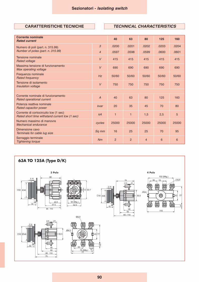
90
Corrente nominaleRated current 40 63 80 125 160
Numero di poli (part. n. 315.99)Number of poles (part. n. 315.99)
3 .0200 .0201 .0202 .0203 .0204
4 .0597 .0598 .0599 .0600 .0601
Tensione nominaleRated voltage
V 415 415 415 415 415
Massima tensione di funzionamentoMax operating voltage
V 690 690 690 690 690
Frequenza nominaleRated frequency
Hz 50/60 50/60 50/60 50/60 50/60
Tensione di isolamentoInsulation voltage
V 750 750 750 750 750
Corrente nominale di funzionamentoRated operational current
A 40 63 80 125 160
Potenza reattiva nominaleRated capacitor power
kvar 20 35 45 70 80
Corrente di cortocircuito lcw (1 sec)Rated short time withstand current lcw (1 sec)
kA 1 1 1,5 2,5 5
Numero massimo di manovreMechanical endurance
cycles 25000 25000 25000 25000 25000
Dimensione cavoTerminals for cable lug size
Sq mm 16 25 25 70 95
Serraggio terminaleTightening torque
Nm 2 2 4 6 6
Sezionatori - Isolating switch
CARATTERISTICHE TECNICHE TECHNICAL CHARACTERISTICS
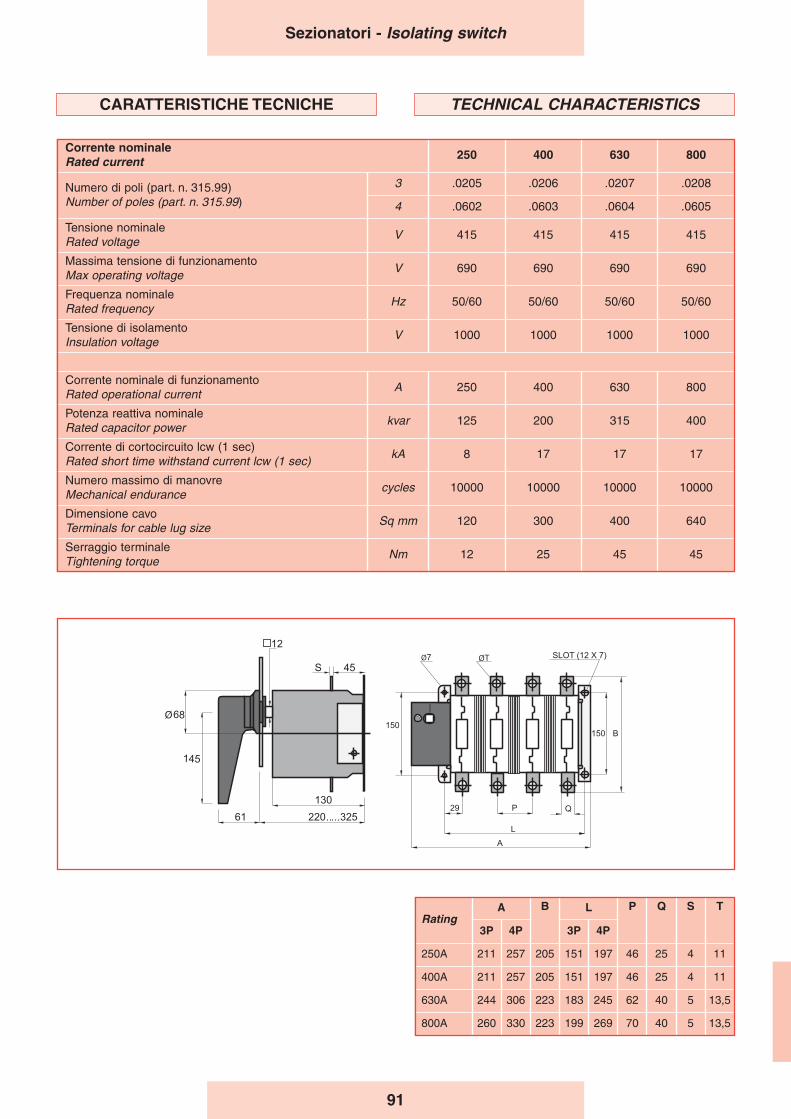
91
Sezionatori - Isolating switch
Corrente nominaleRated current 250 400 630 800
Numero di poli (part. n. 315.99)Number of poles (part. n. 315.99)
3 .0205 .0206 .0207 .0208
4 .0602 .0603 .0604 .0605
Tensione nominaleRated voltage
V 415 415 415 415
Massima tensione di funzionamentoMax operating voltage
V 690 690 690 690
Frequenza nominaleRated frequency
Hz 50/60 50/60 50/60 50/60
Tensione di isolamentoInsulation voltage
V 1000 1000 1000 1000
Corrente nominale di funzionamentoRated operational current
A 250 400 630 800
Potenza reattiva nominaleRated capacitor power
kvar 125 200 315 400
Corrente di cortocircuito lcw (1 sec)Rated short time withstand current lcw (1 sec)
kA 8 17 17 17
Numero massimo di manovreMechanical endurance
cycles 10000 10000 10000 10000
Dimensione cavoTerminals for cable lug size
Sq mm 120 300 400 640
Serraggio terminaleTightening torque
Nm 12 25 45 45
CARATTERISTICHE TECNICHE TECHNICAL CHARACTERISTICS
RatingA B L P Q S T
3P 4P 3P 4P
250A 211 257 205 151 197 46 25 4 11
400A 211 257 205 151 197 46 25 4 11
630A 244 306 223 183 245 62 40 5 13,5
800A 260 330 223 199 269 70 40 5 13,5
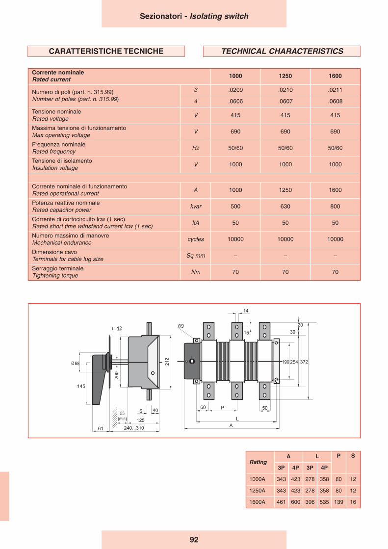
92
Sezionatori - Isolating switch
Corrente nominaleRated current 1000 1250 1600
Numero di poli (part. n. 315.99)Number of poles (part. n. 315.99)
3 .0209 .0210 .0211
4 .0606 .0607 .0608
Tensione nominaleRated voltage
V 415 415 415
Massima tensione di funzionamentoMax operating voltage
V 690 690 690
Frequenza nominaleRated frequency
Hz 50/60 50/60 50/60
Tensione di isolamentoInsulation voltage
V 1000 1000 1000
Corrente nominale di funzionamentoRated operational current
A 1000 1250 1600
Potenza reattiva nominaleRated capacitor power
kvar 500 630 800
Corrente di cortocircuito lcw (1 sec)Rated short time withstand current lcw (1 sec)
kA 50 50 50
Numero massimo di manovreMechanical endurance
cycles 10000 10000 10000
Dimensione cavoTerminals for cable lug size
Sq mm – – –
Serraggio terminaleTightening torque
Nm 70 70 70
CARATTERISTICHE TECNICHE TECHNICAL CHARACTERISTICS
RatingA L P S
3P 4P 3P 4P
1000A 343 423 278 358 80 12
1250A 343 423 278 358 80 12
1600A 461 600 396 535 139 16
93
Reference Notes -Warnings
Note di riferimento -Avvertenze
The capacitors and the automatic power factor correctionequipment must be installed in well-ventilated areas.
The air should be able to circulate freely through the airvents. The ambient temperature must comply with EN60831-1/2 standards.
When the system subject to power factor correction hasAC/DC static conversion systems (e.g. for the operation ofDC motors, uninterrupted power systems, etc.), harmoniccurrents are generated and may cause either current orvoltage overloads which the capacitors are unable towithstand.DUCATI energia can provide properly protected equipmentsuitable for use in such systems as well as filter systemsdesigned to eliminate harmonic components.
When the capacitors are used in automatic equipment, besure to check that the regulator response time is greaterthan the capacitor discharge time. If this is not the case,suitable discharge resistors should be installed.
The use of rigid connections should be avoided withcylindrical capacitors in order to avoid blocking theintervention of the overpressure device. For this reason atleast 3 cm should be left between the terminals and anysurface above the upper capacitor.
In the automatic equipment the integrity of the pre-chargingresistors should be checked every 10.000 operations or atleast once a year.Plan to replace the contactors every 100.000 operations.
The guarantee does not cover problems arising fromoperation:
- in the presence of excessive harmonic overloads (>1.3 In,>1.1 Un.)
- Contactors with worn-out electrical contacts or interruptedpre-charging resistors.
I condensatori e le apparecchiature automatiche dirifasamento devono essere installati in ambiente ben areato.
L’aria deve poter circolare liberamente attraverso le fessuredi ventilazione.La temperatura ambiente deve essere contenuta e conformea quanto specificato dalla normativa CEI EN 60831-1/2.
Quando nell’impianto da rifasare siano presenti sistemi diconversione statica CA/CC, ad esempio per l’azionamento dimotori in corrente continua, gruppi di continuità, ecc., questigenerano correnti armoniche della fondamentale chepossono determinare sovraccarichi sia di corrente che ditensione inammissibili per i condensatori.DUCATI energia è in grado di fornire apparecchiatureadeguatamente protette adatte ad essere utilizzate in questiimpianti oltre che sistemi per l’eliminazione delle componentiarmoniche.
Quando i condensatori vengono utilizzati in apparecchiatureautomatiche, avere cura di verificare che i tempi di interventodel regolatore siano superiori al tempo di scarica deicondensatori. In caso contrario prevedere adatte resistenzedi scarica.
Evitare l’uso di collegamenti rigidi per i condensatori cilindriciin modo che l’intervento del dispositivo a sovrapressionenon sia impedito. Per lo stesso motivo lasciare almeno 3 cmfra i terminali e qualsiasi superficie al di sopra delcondensatore superiore.
Per le apparecchiature automatiche controllare l’integrità deiresistori di precarica ogni 10.000 manovre o almeno unavolta all’anno.Pianificare la sostituzione dei contattori ogni 100.000manovre.
La garanzia decade per gli inconvenienti derivanti dafunzionamento:
- In presenza di eccessivi sovraccarichi armonici (>1.3 In,>1.1 Un).
- Contatti elettrici dei contattori usurati o resistori di precariainterotti.
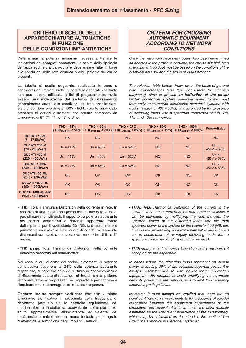
CRITERIO DI SCELTA DELLEAPPARECCHIATURE AUTOMATICHE
IN FUNZIONE DELLE CONDIZIONI IMPIANTISTICHE
Determinata la potenza massima necessaria tramite leindicazioni dei paragrafi precedenti, la scelta della tipologiadell’apparecchiatura da adottare deve essere fatte in basealle condizioni della rete elettrica e alle tipologie del caricopresenti.
La tabella di scelta seguente, realizzata in base aconsiderazioni impiantistiche di carattere generale (pertantonon può essere utilizzata a fini di progettazione), vuoleessere una indicazione del sistema di rifasamentogeneralmente adatto alle condizioni più frequenti: impiantielettrici con tensione di rete 400V - 50Hz caratterizzati dallapresenza di carichi distorcenti con spettro composto daarmoniche di 5°, 7°, 11° e 13° ordine.
CRITERIA FOR CHOOSING AUTOMATIC EQUIPMENT
ACCORDING TO NETWORK CONDITIONS
Once the maximum necessary power has been determinedas directed in the previous sections, the choice of which typeof equipment to adopt must be based on the conditions of theelectrical network and the types of loads present.
The selection table below, drawn up on the basis of generalplant characteristics (and thus not usable for planningpurposes), aims to provide an indication of the powerfactor correction system generally suited to the mostfrequently encountered conditions; electrical systems withmains voltage of 400V-50Hz, characterized by the presenceof distorting loads with a spectrum composed of 5th, 7th,11th and 13th harmonics.
- THDI: Total Harmonics Distorsion della corrente in rete. Inassenza di una misura che possa fornire tale dato, esso sipuò stimare moltiplicando il rapporto tra potenza apparentedei carichi distorcenti e potenza apparente totaledell’impianto per il coefficiente 30 (NB: tale assunzione èpuramente indicativa e tiene conto di carichi mediamentedistorcenti con spettro composto da armoniche di 5° e 7°ordine.
- THDI (MAXC): Total Harmonics Distorsion della correntemassima accettata sui condensatori.
Nel caso in cui vi siano dei carichi distorcenti di potenzacomplessiva superiore al 25% della potenza apparentedisponibile, si consiglia sempre l’utilizzo di apparecchiaturedi rifasamento dotate di reattanze, al fine di non amplificarele correnti armoniche presenti nell’impianto e per contenerel’inquinamento elettromagnetico in bassa frequenza.
Occorre inoltre sempre verificare che non vi sianoarmoniche significative in prossimità della frequenza dirisonanza parallelo tra la capacità equivalente deicondensatori e l’induttanza equivalente dell’impianto (disolito approssimabile all’induttanza equivalente deltrasformatore) calcolabile nel modo indicato al paragrafo“L’effetto delle Armoniche negli Impianti Elettrici”.
- THDI: Total Harmonics Distortion of the current in thenetwork. If no measurement of this parameter is available, itcan be estimated by multiplying the ratio between theapparent power of the distorting loads and the totalapparent power of the system by the coefficient 30 (NB: thismethod will provide only an approximate value and is basedon an assumption of averagely distorting loads with aspectrum composed of 5th and 7th harmonics).
- THDI (MAXC): Total Harmonics Distortion of the max currentaccepted on the capacitors.
In cases where the distorting loads represent an overallpower exceeding 25% of the available apparent power, it isalways recommended to use power factor correctionequipment with reactors to avoid amplifying the harmoniccurrents present in the network and to limit low-frequencyelectromagnetic pollution.
Moreover, it must always be verified that there are nosignificant harmonics in proximity to the frequency of parallelresonance between the equivalent capacitance of thecapacitors and equivalent inductance of the plant (usuallyestimated as the equivalent inductance of the transformer),which may be calculated as described in the section “TheEffect of Harmonics in Electrical Systems”.
Dimensionamento del rifasamento - PFC Sizing
94
THD < 12%(THDI(MAXC) < 50%)
THD < 20%(THDI(MAXC) < 70%)
THD < 27%(THDI(MAXC) < 85%)
THD < 80%(THDI(MAXC) < 95%)
THD < 100%(THDI (MAXC) < 100%)
Fotovoltaico
DUCATI 18-M(5 - 17,5kVAr)
OK NO NO NO NO NO
DUCATI 200-M(20 - 200kVAr)
Un = 415V Un = 450V Un = 525V NO NOUn =
450V o 525V
DUCATI 400-M(220 - 400kVAr)
Un = 415V Un = 450V Un = 525V NO NOUn =
450V o 525V
DUCATI 1600R(240 - 1600kVAr)
Un = 415V Un = 450V Un = 525V NO NOUn =
450V o 525V
DUCATI 170-ML(25,5 - 170kVAr)
OK OK OK OK NO OK
DUCATI 1000-RL(150 - 1000kVAr)
OK OK OK OK NO OK
DUCATI 1000-RL/HP(150 - 1000kVAr)
OK OK OK OK OK OK
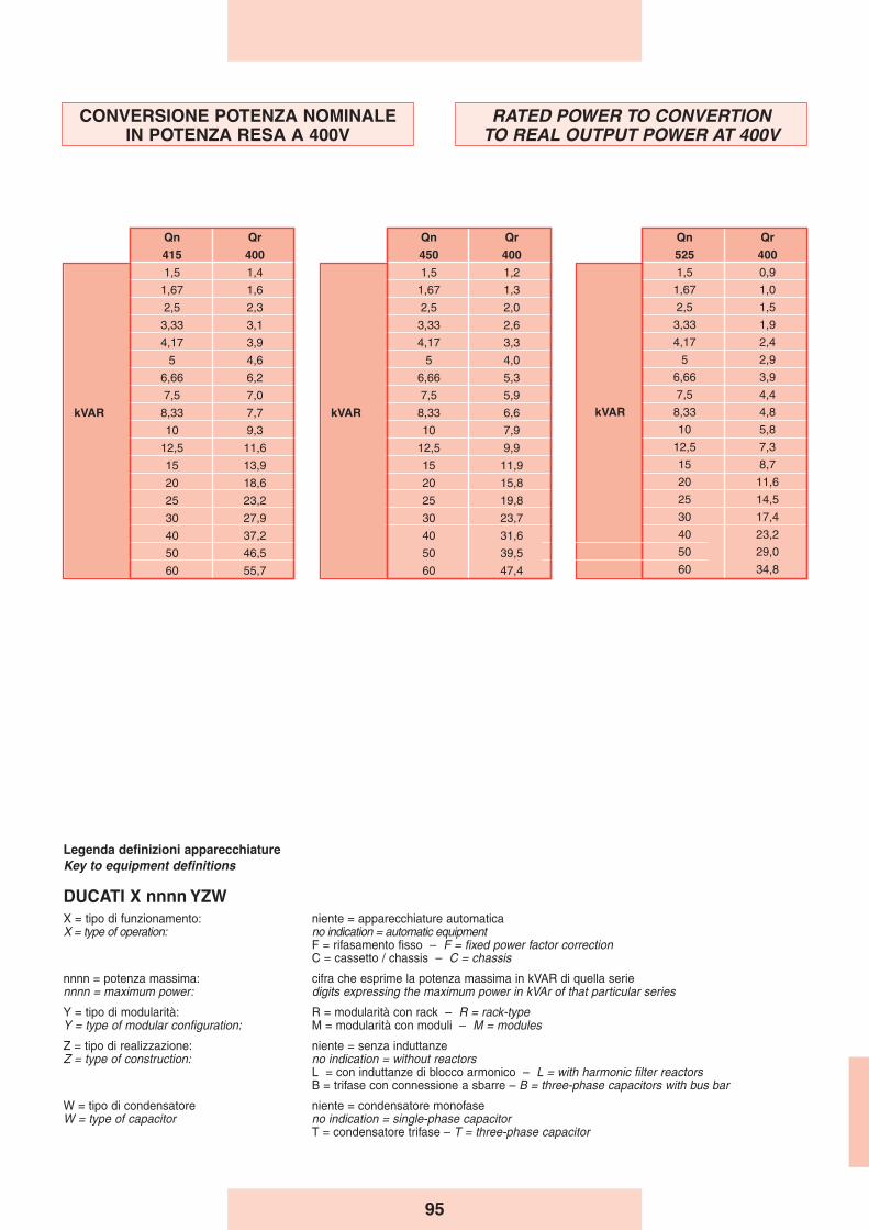
95
CONVERSIONE POTENZA NOMINALEIN POTENZA RESA A 400V
RATED POWER TO CONVERTIONTO REAL OUTPUT POWER AT 400V
Qn Qr
525 400
1,5 0,9
1,67 1,0
2,5 1,5
3,33 1,9
4,17 2,4
5 2,9
6,66 3,9
7,5 4,4
kVAR 8,33 4,8
10 5,8
12,5 7,3
15 8,7
20 11,6
25 14,5
30 17,4
40 23,2
50 29,0
60 34,8
Qn Qr
450 400
1,5 1,2
1,67 1,3
2,5 2,0
3,33 2,6
4,17 3,3
5 4,0
6,66 5,3
7,5 5,9
kVAR 8,33 6,6
10 7,9
12,5 9,9
15 11,9
20 15,8
25 19,8
30 23,7
40 31,6
50 39,5
60 47,4
Qn Qr
415 400
1,5 1,4
1,67 1,6
2,5 2,3
3,33 3,1
4,17 3,9
5 4,6
6,66 6,2
7,5 7,0
kVAR 8,33 7,7
10 9,3
12,5 11,6
15 13,9
20 18,6
25 23,2
30 27,9
40 37,2
50 46,5
60 55,7
Legenda definizioni apparecchiatureKey to equipment definitions
DUCATI X nnnn YZWX = tipo di funzionamento: niente = apparecchiature automaticaX = type of operation: no indication = automatic equipment
F = rifasamento fisso – F = fixed power factor correction C = cassetto / chassis – C = chassis
nnnn = potenza massima: cifra che esprime la potenza massima in kVAR di quella seriennnn = maximum power: digits expressing the maximum power in kVAr of that particular series
Y = tipo di modularità: R = modularità con rack – R = rack-typeY = type of modular configuration: M = modularità con moduli – M = modules
Z = tipo di realizzazione: niente = senza induttanzeZ = type of construction: no indication = without reactors
L = con induttanze di blocco armonico – L = with harmonic filter reactorsB = trifase con connessione a sbarre – B = three-phase capacitors with bus bar
W = tipo di condensatore niente = condensatore monofaseW = type of capacitor no indication = single-phase capacitor
T = condensatore trifase – T = three-phase capacitor
96
Notes

Via M.E. Lepido, 182 - 40132 Bologna - ItalyTel. +39 051 6411511 - Fax +39 051 402040
www.ducatienergia.com - E-mail: [email protected]
Per
la c
ontin
ua e
volu
zion
e de
lla n
ostr
a te
cnol
ogia
, ci r
iser
viam
o il
dirit
to d
i cam
biar
e le
sud
dette
spe
cific
he s
enza
pre
avvi
so.
Due
to th
e co
ntin
ual d
evel
ompe
nt o
f our
tech
nolo
gy, w
e re
serv
e th
e rig
ht to
cha
nge
the
abov
e sp
ecifi
catio
ns.
HISTORY DRIVES THE FUTURE
TIP
OLI
TO
RIG
FH
I 03-
2015
(82
99)