Embed Size (px)
Citation preview

White Paper
RFC 2547bis: BGP/MPLS VPN Fundamentals
Juniper Networks, Inc.1194 North Mathilda AvenueSunnyvale, CA 94089 USA408 745 2001 or 888 JUNIPERwww.juniper.net
Part Number : 200012-001 03/01
Chuck SemeriaMarketing Engineer

Contents
Executive Summary . . . . . . . . . . . . . . . . . . . . . . . . . . . . . . . . . . . . . . . . . . . . . . . . . . . . . . . . . . . . 5BGP/MPLS VPN Overview . . . . . . . . . . . . . . . . . . . . . . . . . . . . . . . . . . . . . . . . . . . . . . . . . . . . . 6
Network Components . . . . . . . . . . . . . . . . . . . . . . . . . . . . . . . . . . . . . . . . . . . . . . . . . . . . . . 6Customer Edge Devices . . . . . . . . . . . . . . . . . . . . . . . . . . . . . . . . . . . . . . . . . . . . . . . . . 7Provider Edge Routers . . . . . . . . . . . . . . . . . . . . . . . . . . . . . . . . . . . . . . . . . . . . . . . . . . . 7Provider Routers . . . . . . . . . . . . . . . . . . . . . . . . . . . . . . . . . . . . . . . . . . . . . . . . . . . . . . . 7
Operational Model . . . . . . . . . . . . . . . . . . . . . . . . . . . . . . . . . . . . . . . . . . . . . . . . . . . . . . . . 7Sample Network Topology . . . . . . . . . . . . . . . . . . . . . . . . . . . . . . . . . . . . . . . . . . . . . . . 7Control Flow . . . . . . . . . . . . . . . . . . . . . . . . . . . . . . . . . . . . . . . . . . . . . . . . . . . . . . . . . . 8Data Flow . . . . . . . . . . . . . . . . . . . . . . . . . . . . . . . . . . . . . . . . . . . . . . . . . . . . . . . . . . . 10
Benefits of BGP/MPLS VPNs . . . . . . . . . . . . . . . . . . . . . . . . . . . . . . . . . . . . . . . . . . . . . . 11Challenges and Solutions . . . . . . . . . . . . . . . . . . . . . . . . . . . . . . . . . . . . . . . . . . . . . . . . . . . . . . 12
Overlapping Customer Address Spaces . . . . . . . . . . . . . . . . . . . . . . . . . . . . . . . . . . . . . 12VPN-IPv4 Address Family . . . . . . . . . . . . . . . . . . . . . . . . . . . . . . . . . . . . . . . . . . . . . . 12Multiprotocol BGP Extensions . . . . . . . . . . . . . . . . . . . . . . . . . . . . . . . . . . . . . . . . . . . 13
Constraining Network Connectivity . . . . . . . . . . . . . . . . . . . . . . . . . . . . . . . . . . . . . . . . 14Multiple Forwarding Tables . . . . . . . . . . . . . . . . . . . . . . . . . . . . . . . . . . . . . . . . . . . . . 14BGP Extended Community Attributes . . . . . . . . . . . . . . . . . . . . . . . . . . . . . . . . . . . . . 15
Maintaining Updated VPN Routing Information . . . . . . . . . . . . . . . . . . . . . . . . . . . . . . 18Conserving Backbone Bandwidth and PE Router Packet Processing Resources . . . . 19
Case Study: A Single Service Provider Backbone . . . . . . . . . . . . . . . . . . . . . . . . . . . . . . . . . . 20Distribution of VPN Routing Information . . . . . . . . . . . . . . . . . . . . . . . . . . . . . . . . . . . . 22
CE Router to Ingress PE Route Distribution . . . . . . . . . . . . . . . . . . . . . . . . . . . . . . . . . 22Ingress PE to Egress PE Route Distribution Across Backbone . . . . . . . . . . . . . . . . . . 24Egress PE Router to CE Route Distribution . . . . . . . . . . . . . . . . . . . . . . . . . . . . . . . . . 28
Forwarding Customer VPN Traffic Across the BGP/MPLS Backbone . . . . . . . . . . . . 29Source CE Router to Ingress PE Router Forwarding . . . . . . . . . . . . . . . . . . . . . . . . . . 30Ingress PE Router Forwarding . . . . . . . . . . . . . . . . . . . . . . . . . . . . . . . . . . . . . . . . . . . 30P Router Forwarding . . . . . . . . . . . . . . . . . . . . . . . . . . . . . . . . . . . . . . . . . . . . . . . . . . . 30PE Router to Destination CE Router Forwarding . . . . . . . . . . . . . . . . . . . . . . . . . . . . . 30Example #1: Forwarding VPN Red Traffic from Site 1 to Site 4 . . . . . . . . . . . . . . . . . 31Example #2: Forwarding VPN Red Traffic from Site 4 to Site 1 . . . . . . . . . . . . . . . . . 32Example #3: Forwarding VPN Green Traffic from Site 6 to Site 7 . . . . . . . . . . . . . . . 33
Accessing the Public Internet from a VPN Site . . . . . . . . . . . . . . . . . . . . . . . . . . . . . . . . . . . . 35Non-VRF Internet Access . . . . . . . . . . . . . . . . . . . . . . . . . . . . . . . . . . . . . . . . . . . . . . . . . . 35
VPN Hosts to Public Internet . . . . . . . . . . . . . . . . . . . . . . . . . . . . . . . . . . . . . . . . . . . . 36Public Internet to VPN Hosts . . . . . . . . . . . . . . . . . . . . . . . . . . . . . . . . . . . . . . . . . . . . 36
Scalability of BGP/MPLS VPNs . . . . . . . . . . . . . . . . . . . . . . . . . . . . . . . . . . . . . . . . . . . . . . . . . 36
Copyright © 2001, Juniper Networks, Inc.

Conclusion . . . . . . . . . . . . . . . . . . . . . . . . . . . . . . . . . . . . . . . . . . . . . . . . . . . . . . . . . . . . . . . . . . . 37References . . . . . . . . . . . . . . . . . . . . . . . . . . . . . . . . . . . . . . . . . . . . . . . . . . . . . . . . . . . . . . . . . . . 38
Internet Drafts . . . . . . . . . . . . . . . . . . . . . . . . . . . . . . . . . . . . . . . . . . . . . . . . . . . . . . . . . . . 38Requests for Comments . . . . . . . . . . . . . . . . . . . . . . . . . . . . . . . . . . . . . . . . . . . . . . . . . . . 38Textbooks . . . . . . . . . . . . . . . . . . . . . . . . . . . . . . . . . . . . . . . . . . . . . . . . . . . . . . . . . . . . . . . 38
Copyright © 2001, Juniper Networks, Inc. . 3

RFC 2547bis: BGP/MPLS VPN Fundamentals
List of Figures
Figure 1: RFC 2547bis Network Components . . . . . . . . . . . . . . . . . . . . . . . . . . . . . . . . . . . . . . 6Figure 2: Sample BGP/MPLS VPN Network Topology . . . . . . . . . . . . . . . . . . . . . . . . . . . . . 8Figure 3: LSPs Between Site 1 and Site 2 . . . . . . . . . . . . . . . . . . . . . . . . . . . . . . . . . . . . . . . . . . 9Figure 4: Data Flow from Site 2 to Site 1 . . . . . . . . . . . . . . . . . . . . . . . . . . . . . . . . . . . . . . . . . 10Figure 5: Encoding of Route Distinguishers and IPv4 Addresses . . . . . . . . . . . . . . . . . . . . 12Figure 6: A PE Router Populates a VPN Routing and Forwarding Table . . . . . . . . . . . . . 15Figure 7: Full-mesh VPN Connectivity . . . . . . . . . . . . . . . . . . . . . . . . . . . . . . . . . . . . . . . . . . . 17Figure 8: Hub-and-spoke VPN Connectivity . . . . . . . . . . . . . . . . . . . . . . . . . . . . . . . . . . . . . 18Figure 9: Case Study: Network Topology . . . . . . . . . . . . . . . . . . . . . . . . . . . . . . . . . . . . . . . . 20Figure 10: Case Study: Label Switched Paths . . . . . . . . . . . . . . . . . . . . . . . . . . . . . . . . . . . . . 21Figure 11: Case Study: Generic Configuration for PE 1 . . . . . . . . . . . . . . . . . . . . . . . . . . . . 21Figure 12: Case Study: Generic Configuration for PE 2 . . . . . . . . . . . . . . . . . . . . . . . . . . . . 22Figure 13: Case Study: Generic Configuration for PE 3 . . . . . . . . . . . . . . . . . . . . . . . . . . . . 22Figure 14: Forwarding VPN Red Traffic from Site 1 to Site 4 . . . . . . . . . . . . . . . . . . . . . . . 31Figure 15: Forwarding VPN Red Traffic from Site 4 to Site 1 . . . . . . . . . . . . . . . . . . . . . . . 32Figure 16: Forwarding VPN Red Traffic from Site 6 to Site 7 . . . . . . . . . . . . . . . . . . . . . . . 34Figure 17: Non-VRF Internet Access . . . . . . . . . . . . . . . . . . . . . . . . . . . . . . . . . . . . . . . . . . . . . 35
4 Copyright © 2001, Juniper Networks, Inc.

Executive Summary
Until recently, there has always been a clear distinction between public and private networks. A public network, like the plain old telephone service (POTS) or the Internet, is a collection of unrelated systems that are allowed to exchange information freely with each other. A private network is composed of computers that are owned and administered by a single organization that share information with each other. Different sites in a private network are interconnected using dedicated leased lines to ensure that inter-site connectivity is always private. An enterprise that deploys a private network is assured that it is the only organization using the network.
While deploying a single VPN service model would simplify network operations, this approach cannot satisfy diverse customer requirements because each subscriber is unique. Each customer has different security concerns, number of sites, number of users, routing complexity, mission-critical applications, traffic patterns, traffic volumes, staff networking expertise, and willingness to outsource network services. To satisfy a broad range of customer requirements, service providers must offer subscribers a portfolio that contains a number of different VPN service delivery models. Over the years, a number of diverse VPN models have been proposed.
■ Traditional VPNs
■ Frame Relay (Layer 2)
■ ATM (Layer 2)
■ CPE-based VPNs
■ L2TP and PPTP (Layer 2)
■ IPSec (Layer 3)
■ Provider Provisioned VPNs (PP-VPNs)
■ MPLS-based Layer 2 VPNs
■ BGP/MPLS VPNs or RFC2547bis (Layer 3)
This paper focuses on developing a detailed understanding of the VPN service model proposed in RFC 2547bis, which is generating a tremendous amount of interest in the service provider community. It provides a mechanism that simplifies WAN operations for a diverse set of customers that have limited IP routing expertise. RFC 2547bis is a way to efficiently scale the network while delivering revenue-generating, value-added services.
Copyright © 2001, Juniper Networks, Inc. . 5

RFC 2547bis: BGP/MPLS VPN Fundamentals
BGP/MPLS VPN Overview
RFC 2547bis defines a mechanism that allows service providers to use their IP backbone to provide VPN services to their customers. RFC 2547bis VPNs are also known as BGP/MPLS VPNs because BGP is used to distribute VPN routing information across the provider's backbone and because MPLS is used to forward VPN traffic from one VPN site to another.
The primary objectives of this approach are as follows.
■ Make the service very simple for customers to use even if they lack experience in IP routing.
■ Make the service very scalable and flexible to facilitate large-scale deployment.
■ Allow the policies that are used to create a VPN to be implemented by the service provider alone, or by the service provider working together with the customer.
■ Allow the service provider to deliver a critical value-added service that galvanizes customer loyalty.
Network Components
In the context of RFC 2547bis, a VPN is a collection of policies, and these policies control connectivity among a set of sites. A customer site is connected to the service provider network by one or more ports, where the service provider associates each port with a VPN routing table. In RFC 2547bis terms, the VPN routing table is called a VPN routing and forwarding (VRF) table. Figure 1 illustrates the fundamental building blocks of a BGP/MPLS VPN.
Figure 1: RFC 2547bis Network Components
CE = Customer EdgeP = Provider RoutersPE = Provider Edge
Site 2Red VPN
Site 1Red VPN
CE
PEP
P
P
Provider Network
Site 3Blue VPN
Site 4Blue VPN
CE
CE
PE
CE
M40
M40
M20M10
M160
6 Copyright © 2001, Juniper Networks, Inc.

RFC 2547bis: BGP/MPLS VPN Fundamentals
Customer Edge Devices
A customer edge (CE) device provides customer access to the service provider network over a data link to one or more provider edge (PE) routers. While the CE device can be a host or a Layer 2 switch, typically the CE device is an IP router that establishes an adjacency with its directly connected PE routers. After the adjacency is established, the CE router advertises the site’s local VPN routes to the PE router and learns remote VPN routes from the PE router.
Provider Edge Routers
PE routers exchange routing information with CE routers using static routing, RIPv2, OSPF, or EBGP. While a PE router maintains VPN routing information, it is only required to maintain VPN routes for those VPNs to which it is directly attached. This design enhances the scalability of RFC 2547bis model because it eliminates the need for PE routers to maintain all of the service provider's VPN routes.
Each PE router maintains a VRF for each of its directly connected sites. Each customer connection (such as Frame Relay PVC, ATM PVC, and VLAN) is mapped to a specific VRF. Thus, it is a port on the PE router and not a site that is associated with a VRF. Note that multiple ports on a PE router can be associated with a single VRF. It is the ability of PE routers to maintain multiple forwarding tables that supports the per-VPN segregation of routing information.
After learning local VPN routes from CE routers, a PE router exchanges VPN routing information with other PE routers using IBGP. PE routers can maintain IBGP sessions to route reflectors as an alternative to a full mesh of IBGP sessions. Deploying multiple route reflectors enhances the scalability of the RFC 2547bis model because it eliminates the need for any single network component to maintain all VPN routes.
Finally, when using MPLS to forward VPN data traffic across the provider’s backbone, the ingress PE router functions as the ingress LSR and the egress PE router functions as the egress LSR.
Provider Routers
A provider (P) router is any router in the provider's network that does not attach to CE devices. P routers function as MPLS transit LSRs when forwarding VPN data traffic between PE routers. Since traffic is forwarded across the MPLS backbone using a two layer label stack, P routers are only required to maintain routes to the provider’s PE routers; they are not required to maintain specific VPN routing information for each customer site.
Operational Model
Two fundamental traffic flows occur in a BGP/MPLS VPN.
■ A control flow that is used for VPN route distribution and label switched path (LSP) establishment
■ A data flow that is used to forward customer data traffic
Sample Network Topology
Figure 2 provides a sample network topology where a single service provider delivers a BGP/MPLS VPN service to different enterprises customers. In this network there are two PE routers connected to four different customer sites.
Copyright © 2001, Juniper Networks, Inc. . 7

RFC 2547bis: BGP/MPLS VPN Fundamentals
Figure 2: Sample BGP/MPLS VPN Network Topology
The inter-site connectivity can be described by the following policies.
■ Any host in Site 1 can communicate with any host in Site 2.
■ Any host in Site 2 can communicate with any host in Site 1.
■ Any host in Site 3 can communicate with any host in Site 4.
■ Any host in Site 4 can communicate with any host in Site 3.
Control Flow
In a BGP/MPLS VPN, the control flow consists of two subflows.
■ The first control subflow is responsible for the exchange of routing information between the CE and PE routers at the edges of the provider's backbone and between the PE routers across the provider's backbone.
■ The second control subflow is responsible for the establishment of LSPs across the provider’s backbone between PE routers.
Exchange of Routing Information
In this example, PE 1 is configured to associate VRF Red with the interface or subinterface over which it learns routes from CE 1. When CE 1 advertises the route for prefix 10.1/16 to PE 1, PE 1 installs a local route to 10.1/16 in VRF Red.
PE 1 advertises the route for 10.1/16 to PE 2 using IBGP. Before advertising the route, PE 1 selects an MPLS label (for this example, 222) to advertise with the route and assigns its loopback address as the BGP next hop for the route.
RFC 2547bis supports overlapping address spaces (private addressing defined in RFC 1918) by the use of route distinguishers (RDs) and the VPN-IPv4 address family.
CE = Customer EdgeP = Provider RoutersPE = Provider EdgeVRF = VPN Routing and Forwarding Table
Site 210.2/16
Site 110.1/16
CE 1
PE 1P
P
P
Provider Network
Site 310.2/16
Site 410.1/16
CE 4
CE 2
PE 2
CE 3
M40
M40
M20M10
M160
VRF
VRF
VRF
VRF
8 Copyright © 2001, Juniper Networks, Inc.

RFC 2547bis: BGP/MPLS VPN Fundamentals
RFC 2547bis constrains the distribution of routing information among PE routers by the use of route filtering based on BGP extended community attributes (route targets).
When PE 2 receives PE 1's route advertisement, it determines if it should install the route to prefix 10.1/16 into VRF Red by performing route filtering based on the BGP extended community attributes carried with the route. If PE 2 decides to install the route in VRF Red, it then advertises the route to prefix 10.1/16 to CE 2.
LSP Establishment
In order to use MPLS to forward VPN traffic across the provider's backbone, LSPs must be established between the PE router that learns the route and the PE router that advertises the route (Figure 3).
Figure 3: LSPs Between Site 1 and Site 2
LSPs can be established and maintained across the service provider's network using either Label Distribution Protocol (LDP) or Resource Reservation Protocol (RSVP).
■ The provider uses LDP if it wants to establish a best-effort LSP between two PE routers. In this case, the LSP follows the same route as best-effort traffic.
■ The provider uses RSVP if it wants to either assign bandwidth to the LSP or use traffic engineering to select an explicit path for the LSP. RSVP-based LSPs support specific quality of service (QoS) guarantees and/or specific traffic engineering objectives.
To ensure multivendor interoperability, all PE and P routers are required to support LDP at a minimum.
■ If the provider elects to use LDP, a full mesh of best-effort LSPs is established across the backbone to support PE-to-PE connectivity.
■ If the provider elects to use RSVP, RSVP-based LSPs have a higher priority than LDP-based LSPs. Both an LDP-based and an RSVP-based LSP exist between a pair of PE routers, the ingress label switching router (LSR) selects the RSVP-based LSP instead of the LDP-based LSP. This model supports the incremental configuration of RSV-based LSPs across the service provider ’s backbone.
Site 210.2/16
Site 110.1/16
CE 1
PE 1
Provider Network
Site 310.2/16
Site 410.1/16
CE 4
CE 2
PE 2
CE 3
M40
M40
M20M10
M160
VRF
VRF
VRF
VRF
LSP
LSP
Copyright © 2001, Juniper Networks, Inc. . 9

RFC 2547bis: BGP/MPLS VPN Fundamentals
Note that there can be a single LSP or several parallel LSPs (perhaps with different QoS capabilities) established between PE routers. Also, a route reflector simply acts as server that reflects routes from an ingress PE router to egress PE routers. If a provider uses route reflection, it is still required to establish LSPs between PE routers because route reflectors are not necessarily part of the transit path between PE routers.
Data Flow
Figure 4 shows the flow of VPN data traffic across the service provider’s backbone from one customer site to another customer site. Assume that Host 10.2.3.4 at Site 2 wants to communicate with Server 10.1.3.8 at Site 1.
Figure 4: Data Flow from Site 2 to Site 1
Host 10.2.3.4 forwards all data packets for Server 10.1.3.8 to its default gateway. When a packet arrives at CE 2, it performs a longest-match route lookup and forwards the IPv4 packet to PE 2.
PE 2 receives the packet, performs a route lookup in VRF Red, and obtains the following information.
■ The MPLS label that was advertised by PE 1 with the route (label = 222)
■ The BGP next hop for the route (the loopback address of PE 1)
■ The outgoing subinterface for the LSP from PE 2 to PE 1
■ The initial MPLS label for the LSP from PE 2 to PE 1
User traffic is forwarded from PE 2 to PE 1 using MPLS with a label stack containing two labels. For this data flow, PE 2 is the ingress LSR for the LSP and PE 1 is the egress LSR for the LSP. Before transmitting a packet, PE 2 pushes the label 222 onto the label stack making it the bottom (or inner) label. This label is originally installed in VRF Red when PE 2 receives PE 1's IBGP advertisement for the route to 10.1/16. Next, PE 2 pushes the label associated with the LDP or RSVP-based LSP to PE 1 (the route’s BGP next hop) onto the label stack making it the top (or outer) label.
After creating the label stack, PE 2 forwards the MPLS packet on the outgoing interface to the first P router along the LSP from PE 2 to PE 1. P routers switch packets across the core of the provider's backbone network based on the top label. The penultimate router to PE 1 pops the top label (exposing the bottom or inner label) and forwards the packet to PE 1.
Site 2Host10.2.3.4
Site 1Server10.1.3.8
CE 1
PE 1
Provider Network
Site 310.2/16
Site 410.1/16
CE 4
CE 2
PE 2
CE 3
M40
M40
M20M10
M160
VRF
VRF
VRF
VRF
LSP
10 Copyright © 2001, Juniper Networks, Inc.

RFC 2547bis: BGP/MPLS VPN Fundamentals
When PE 1 receives the packet, it pops the label creating a native IPv4 packet. PE 1 uses the bottom label (222) to identify the directly attached CE that is the next hop to 10.1/16. Finally, PE 1 forwards the native IPv4 packet to CE 1, which forwards the packet to Server 10.1.3.8 at Site 1.
Benefits of BGP/MPLS VPNs
The major objective of BGP/MPLS VPNs is to simplify network operations for customers while allowing the service provider to offer scalable, revenue-generating, value-added services. BGP/MPLS VPNs has many benefits, including the following.
■ There are no constraints on the address plan used by each VPN customer. The customer can use either globally unique or private IP address spaces. From the service provider's perspective, different customers can have overlapping address spaces.
■ The CE router at each customer site does not directly exchange routing information with other CE routers. Customers do not have to deal with inter-site routing issues because inter-site routing issues are the responsibility of the service provider.
■ VPN customers do not have a backbone or a virtual backbone to administer. Thus, customers do not need management access to PE or P routers.
■ Providers do not have a separate backbone or virtual backbone to administer for each customer VPN. Thus, providers do not require management access to CE routers.
■ The policies that determine whether a specific site is a member of a particular VPN are the policies of the customer. The administrative model for RFC 2547bis VPNs allows customer policies to be implemented by the provider alone or by the service provider working together with the customer.
■ The VPN can span multiple service providers. While this capability of BGP/MPLS VPNs is important, this paper does not describe inter-provider VPN solutions.
■ Without the use of cryptographic techniques, security is equivalent to that supported by existing Layer 2 (ATM or Frame Relay) backbone networks.
■ Service providers can use a common infrastructure to deliver both VPN and Internet connectivity services.
■ Flexible and scalable QoS for customer VPN services is supported through the use of the experimental bits in the MPLS shim header or by the use of traffic engineered LSPs (signaled by RSVP).
■ The RFC 2547bis model is link layer (Layer 2) independent.
Copyright © 2001, Juniper Networks, Inc. . 11

RFC 2547bis: BGP/MPLS VPN Fundamentals
Challenges and Solutions
RFC 2547bis uses several mechanisms to enhance the scalability of the approach and solve specific VPN operational issues. These challenges include the following.
■ Supporting overlapping customer address spaces
■ Constraining network connectivity
■ Maintaining updated VPN routing information
■ Conserving backbone bandwidth and PE router packet processing resources
Overlapping Customer Address Spaces
VPN customers often manage their own networks and use the RFC 1918 private address space. If customers do not use globally unique IP addresses, the same 32-bit IPv4 address can be used to identify different systems in different VPNs. The result can be routing difficulties because BGP assumes that each IPv4 address it carries is globally unique. To solve this problem, BGP/MPLS VPNs support a mechanism that converts nonunique IP addresses into globally unique addresses by combining the use of the VPN-IPv4 address family with the deployment of Multiprotocol BGP Extensions (MP-BGP).
VPN-IPv4 Address Family
One challenge posed by overlapping address spaces is that if conventional BGP sees two different routes to the same IPv4 address prefix (where the prefix is assigned to systems in different VPNs), BGP treats the prefixes as if they are equivalent and installs only one route. As a result, the other system is unreachable. Eliminating this problem requires a mechanism that allows BGP to disambiguate the prefixes so that it is possible to install two completely different routes to that address, one for each VPN. RFC 2547bis supports this capability by defining the VPN-IPv4 address family.
A VPN-IPv4 address is a 12-byte quantity composed of an 8-byte RD followed by a 4-byte IPv4 address prefix. Figure 5 shows the structure of a VPN-IPv4 address.
Figure 5: Encoding of Route Distinguishers and IPv4 Addresses
The 8-byte RD is composed of a 2-byte Type field and a 6-byte Value field. The Type field determines the lengths of the Value field’s two subfields (Administrator and Assigned Number), as well as the semantics of the Administrator field. Currently, there are two values defined for the Type field: 0 and 1.
4-Byte IPv4 Address8-Byte Route Distinguisher
TypeField
AdministratorSubfield
Assigned NumberSubfield
IPv4 AddressPrefix
2-ByteType Field
6-Byte Value Field
12 Copyright © 2001, Juniper Networks, Inc.

RFC 2547bis: BGP/MPLS VPN Fundamentals
■ For Type 0, the Administrator subfield contains 2 bytes and the Assigned Number subfield contains 4 bytes. The Administrator subfield holds an autonomous system number (ASN). The use of an ASN from the private ASN space is strongly discouraged. The Assigned Number subfield holds a value from the numbering space administered by the service provider that offers the VPN service and to which the ASN has been assigned.
■ For Type 1, the Administrator subfield contains 4 bytes and the Assigned Number subfield contains 2 bytes. The Administrator subfield holds an IPv4 address. The use of an IP address from the private IP address space is strongly discouraged. The Assigned Number subfield holds a value from the numbering space administered by the service provider that offers the VPN service and to which the ASN has been assigned. A configuration option for Type 1 RDs is to use the loopback address of the PE router that originates the route for the 4-byte Administrator subfield and to select a number that is local to that PE router for the 2-byte Assigned Number subfield.
When configuring RDs on PE routers, RFC 2547bis does not require that all the routes within a VPN use the same RD, and in fact, each VRF within a VPN can use its own RD. However, the service provider must ensure that each RD is globally unique. For this reason, the use of the private ASN space or the private IP address space when defining RDs is strongly discouraged. The use of the public ASN space or the public IP address space guarantees that each RD is globally unique. Globally unique RDs provide a mechanism that allows each service provider to administer its own address space and create globally unique VPN-IPv4 addresses without conflicting with the RD assignments made by other service providers. The use of globally unique RDs supports the following.
■ The creation of distinct routes to a common IPv4 prefix.
■ The creation of multiple, globally unique routes to the same system.
■ The use of policy to decide which packets use which route.
Finally, note these few observations to help avoid confusion concerning how VPN-IPv4 addresses are used in a BGP/MPLS VPN.
■ VPN-IPv4 addresses are used only within the service provider network.
■ VPN customers are not aware of the use of VPN-IPv4 addresses.
■ VPN-IPv4 addresses are carried only in routing protocols that run across the provider's backbone.
■ VPN-IPv4 addresses are not carried in the packet headers of VPN data traffic as it crosses the provider's backbone.
Multiprotocol BGP Extensions
Another limitation of using conventional BGP4 to support BGP/MPLS VPNs is that it was originally designed to carry routing information only for the IPv4 address family. Realizing this limitation, the IETF is working to standardize the Multiprotocol Extensions for BGP4. These extensions were originally defined in RFC 2283 (February 1998) and later updated in RFC 2858 (June 2000). The extensions allow BGP4 to carry routing information for multiple Network Layer protocols (IPv6, IPX, VPN-IPv4, etc.). Therefore, to deploy BGP/MPLS VPNs and support the distribution of VPN-IPv4 routes, PE routers are required to support the MP-BGP extensions and not just conventional BGP.
Before exchanging VPN-IPv4 routing information, RFC 2547bis requires that BGP capabilities negotiation take place to ensure that the BGP peers are both capable of processing the VPN-IPv4 address family. Note that the MP-BGP extensions are backwards compatible so a
Copyright © 2001, Juniper Networks, Inc. . 13

RFC 2547bis: BGP/MPLS VPN Fundamentals
router that supports these extensions can still interoperate with a router that does not support these extensions using conventional BGP4 (however, conventional BGP4 does not support RFC 2547bis VPNs).
Constraining Network Connectivity
Assuming a routing table does not contain a default route, a basic assumption of IP routing is that if the route to a specific network is not installed in a router's forwarding table, the network is unreachable from that router. By constraining the flow of routing information, service providers can efficiently control the flow of customer VPN data traffic. The BGP/MPLS VPN model constrains the flow of routing information using two mechanisms.
■ Multiple forwarding tables
■ BGP extended community attributes
Multiple Forwarding Tables
Each PE router maintains one or more per-site forwarding tables known as VRFs. When a PE router is configured, each of its VRFs is associated with one or more ports (interfaces/subinterfaces) on the PE router that connects directly to the service provider’s customers. If a given site contains hosts that are members of multiple VPNs, the VRF associated with the customer site contains routes for all VPNs of which the site is a member.
When receiving an outbound customer data packet from a directly attached CE router, the PE router performs a route lookup in the VRF that is associated with that site. The specific VRF is determined by the subinterface over which the data packet is received. Support for multiple forwarding tables makes it easy for the PE router to provide the per-VPN segregation of routing information.
Figure 6 illustrates how PE 1 populates VRF Red.
■ PE 1 learns Site 1’s VPN Red routes from CE 1 and installs them into VRF Red.
■ Remote routes are learned via MP-IBGP from other PE routers that are directly connected to sites with hosts that are members of VPN Red. PE 1 learns Site 2’s VPN Red routes from CE 2 and installs them into VRF Red. The import of remote routes into VRF Red is managed by the use of BGP extended community route target attributes.
■ Local VPN Blue routes at Site 4 and remote VPN Blue routes at Site 3 are not associated with VPN Red and are not imported into VRF Red.
14 Copyright © 2001, Juniper Networks, Inc.

RFC 2547bis: BGP/MPLS VPN Fundamentals
Figure 6: A PE Router Populates a VPN Routing and Forwarding Table
There are a number of benefits derived from having PE routers support multiple forwarding tables.
■ Different VPN sites served by the same PE router can use overlapping address spaces.
■ Selection of the specific forwarding table for data traffic is determined by policy (the mapping of a router subinterface to a VRF), and not by the user content of the packet.
■ Multiple forwarding tables prevent communication between sites that have no VPNs in common.
■ Scalability is enhanced because PE routers are not required to maintain a dedicated VRF for all of the VPNs supported by the provider's network. Each PE router is only required to maintain a VRF for each of its directly connected sites.
■ Finally, the backbone network can support multiple different routes to the same system where the route for a specific packet is determined by the site from which the packet enters the provider's backbone.
BGP Extended Community Attributes
The distribution of VPN routing information is constrained through the use of BGP extended community attributes. Extended community attributes are carried in BGP messages as attributes of the route. They identify the route as belonging to a specific collection of routes, all of which are treated the same with respect to routing policy. Each BGP extended community must be globally unique (contains either a public IP address or ASN) and can be used by only one VPN. However, a given customer VPN can make use of multiple globally unique BGP extended communities to help control the distribution of routing information.
BGP/MPLS VPNs use 32-bit BGP extended community attributes instead of conventional 16-bit BGP community attributes. The use of 32-bit extended community attributes enhances
scalability because a single service provider can support a maximum of 232 communities
(not just 216). Since each community attribute contains the provider’s globally unique autonomous system (AS) number, the service provider can control local assignment while also maintaining the global uniqueness of that assignment.
M10
Site 210.2/16
Site 110.1/16
CE 1
PE 1
Provider Network
Site 310.2/16
Site 410.1/16
CE 4
CE 2
PE 2
CE 3
M40
M20
M160
VRF
VRF
LocalRoutes
Remote Routes
VRF
VRF
M40
Copyright © 2001, Juniper Networks, Inc. . 15

RFC 2547bis: BGP/MPLS VPN Fundamentals
RFC 2547bis VPNs can use up to three different types of BGP extended community attributes.
■ The route target attribute identifies a collection of sites (VRFs) to which a PE router distributes routes. A PE router uses this attribute to constrain the import of remote routes into its VRFs.
■ The VPN-of-origin attribute identifies a collection of sites and establishes the associated route as coming from one of the sites in that set.
■ The site-of-origin attribute identifies the specific site from which a PE router learns a route. It is encoded as a route origin extended community attribute, which can be used to prevent routing loops
Operational Model
Before distributing local routes to other PE routers, the ingress PE router attaches a route target attribute to each route learned from directly connected sites. The route target attached to the route is based on the value of the VRFs configured export target policy. This approach provides a tremendous amount of flexibility in the way that a PE router can assign a route target attribute to a route.
■ The ingress PE router can be configured to assign a single route target attribute to all routes learned from a given site.
■ The ingress PE router can be configured to assign one route target attribute to a set of routes learned from a site and other route target attributes to other sets of routes learned from a site.
■ If the CE router communicates with the PE router via EBGP, the CE router can specify one or more route targets for each route. This approach shifts the control of implementing VPN policies from the service provider to the customer.
Before installing remote routes that have been distributed by another PE router, each VRF on an egress PE router is configured with an import target policy. A PE router can only install a VPN-IPv4 route in a VRF if the route target attribute carried with the route matches one of the PE router VRFs import targets.
This approach allows a service provider to use a single mechanism to support VPN customers that have a wide range of inter-site connectivity policies. By careful configuration of export target and import target policies, service providers can construct different types of VPN topologies. The mechanisms that implement the VPN topologies can be completely restricted to the service provider so VPN customers are not aware of this process.
16 Copyright © 2001, Juniper Networks, Inc.

RFC 2547bis: BGP/MPLS VPN Fundamentals
Example 1: Full-mesh VPN Topology
Assume that Corporation Red wants its BGP/MPLS VPN service provider to create a VPN that supports full-mesh site connectivity (Figure 7). Each of the Corporation Red’s sites can send traffic directly to another Corporation Red site, but sites of Corporation Blue receiving BGP/MPLS VPN service from the same service provider cannot send traffic to or receive traffic from Corporation Red sites.
Figure 7: Full-mesh VPN Connectivity
Each Corporation Red site is associated with VRF Red on its PE router. A single globally unique route target (Red) is configured for each VRF Red as both the import target and the export target. This route target (Red) is not assigned to any other VRF as the import or the export target. The result is full-mesh connectivity among Corporation Red sites.
Example 2: Hub-and-spoke VPN Topology
Assume that Corporation Red wants its BGP/MPLS VPN service provider to create a VPN that supports hub-and-spoke site connectivity (Figure 8). The inter-site connectivity for Corporation Red can be described by the following policies.
■ Site 1 can communicate directly with Site 5, but not directly with Site 2. If Site 1 wants to communicate with Site 2, it must sent traffic by way of Site 5.
■ Site 2 can communicate directly with Site 5, but not directly with Site 1. If Site 2 wants to communicate with Site 1, it must sent traffic by way of Site 5.
■ Site 5 can communicate directly with Site 1 and Site 2.
Of course, privacy requires that Corporation Red sites and Corporation Blue sites cannot send traffic to or receive traffic from each other.
Site 2Corp Red
Site 1Corp Red
Site 5Corp Red
Site 4Corp Blue
CE 1
PE 1
Provider Network
Site 3Corp Blue
Site 6Corp Blue
CE 6
CE 4CE 5
CE 2
PE 2
PE 3
CE 3
M20M10
VRF
VRF
M10VRF VRF
VRF
VRF
Exp Target = RedImp Target = Red
Exp Target = RedImp Target = Red
Exp Target = Red Imp Target = RedExp Target = Red Imp Target = Red
Copyright © 2001, Juniper Networks, Inc. . 17

RFC 2547bis: BGP/MPLS VPN Fundamentals
Figure 8: Hub-and-spoke VPN Connectivity
A hub-and-spoke topology is created using two globally unique route target values: hub and spoke.
■ The hub site’s VRF is configured with an export target = hub and an import target = spoke. The VRF at the hub site distributes all of the routes in its VRF with a hub attribute that causes the routes to be imported by the spoke sites. The VRF at the hub site imports all remote routes with a spoke attribute
■ The VRF at each spoke site is configured with an export target = spoke and an import target = hub. The VRF at each spoke site distributes its routes with a spoke attribute, which causes the routes to be imported by the hub site, but dropped by other spoke sites. The VRF at a spoke site imports only routes with a hub attribute, which causes its VRF to be populated only with routes advertised by the hub site.
Maintaining Updated VPN Routing Information
When the configuration of a PE router is changed by creating a new VRF or by adding one or more new import target policies to an existing VRF, the PE router might need to obtain VPN-IPv4 routes that it previously discarded. The speed of delivering updated routing information can present a problem with conventional BGP4 because it is a stateful protocol and does not support the exchange of route refresh request messages and the subsequent re-advertisement of routes. Once BGP peers synchronize their routing tables, they do not exchange routing information until there is a change in that routing information.
A solution to this design feature is provided by the BGP route refresh capability. During the establishment of an MP-IBGP session, a BGP speaker that wants to receive a route refresh message from its peer or route reflector advertises the BGP route refresh capability using a BGP capabilities advertisement. The BGP route refresh capability states that a BGP speaker can send a route refresh message to a peer or route reflector only if it has received a route refresh
Site 2Corp Red
Site 1Corp Red
Site 5Corp Red
Site 4Corp Blue
CE 1
PE 1
Provider Network
Hub
SpokeSpoke
Site 3Corp Blue
Site 6Corp Blue
CE 6
CE 4CE 5
CE 2
PE 2
CE 3
M20M10
VRF
VRF
M10VRF VRF
VRF
VRF
Exp Target = SpokeImp Target = Hub
Exp Target = SpokeImp Target = Hub
Exp Target = Red Imp Target = SpokeExp Target = Hub Imp Target = Spoke
PE 3
18 Copyright © 2001, Juniper Networks, Inc.

RFC 2547bis: BGP/MPLS VPN Fundamentals
capabilities advertisement from that peer or route reflector. Whenever the configuration of a PE router is changed, the PE router can request the retransmission of routing information from its MP-IBGP peers to obtain routing information it previously discarded. When the routes are re-advertised, the updated import target policy is applied as the PE router populates its VRFs.
Conserving Backbone Bandwidth and PE Router Packet Processing Resources
During the process of populating its VRFs, a BGP speaker often receives and then filters unwanted routes from peers based on each VRF’s import target policy. Since the generation, transmission, and processing of routing updates consumes backbone bandwidth and router packet processing resources, these assets can be conserved by eliminating the transmission of unnecessary routing updates.
The number of BGP routing updates can be reduced by enabling the new BGP cooperative route filtering capability. During the establishment of the MP-IBGP session, a BGP speaker that wants to send or receive outbound route filters (ORFs) to or from its peer or route reflector advertises the cooperative route filtering capability using a BGP capabilities advertisement. The BGP speaker sends its peer a set of ORFs that are expressed in terms of BGP communities. The ORF entries are carried in BGP route refresh messages. The peer applies the received ORFs in addition to its locally configured export target policy, to constrain and filter outbound routing updates to the BGP speaker. Note that a BGP peer might or might not honor the ORFs received from a BGP speaker. By implementing this mechanism, BGP cooperative route filtering can be used to conserve service provider backbone bandwidth and PE router packet processing resources.
Copyright © 2001, Juniper Networks, Inc. . 19

RFC 2547bis: BGP/MPLS VPN Fundamentals
Case Study: A Single Service Provider Backbone
Assume a single service provider has an IP backbone to deliver BGP/MPLS VPN services to different enterprises. There are three PE routers in the network connected to seven different customer sites (Figure 9).
Figure 9: Case Study: Network Topology
The following policies describe the desired inter-site connectivity for this case study.
■ Any host in Site 1 can communicate with any host in Site 4.
■ Any host in Site 2 can communicate with any host in Site 5.
■ Any host in Site 3 can communicate with any host in Site 6 and Site 7.
■ Any host in Site 4 can communicate with any host in Site 1.
■ Any host in Site 5 can communicate with any host in Site 2.
■ Any host in Site 6 can communicate with any host in Site 3 and Site 7.
■ Any host in Site 7 can communicate with any host in Site 3 and Site 6.
Assume that the service provider uses RSVP to establish the following LSPs across its backbone (Figure 10). The label displayed at the ingress of each LSP is the label that the PE router associates with the route that it uses to forward traffic to the remote PE router. Note that if the provider uses LDP to establish the LSPs, then the LSPs might not look like point-to-point connections, but rather as multipoint-to-point connections.
PE 1
Provider Network
PE 2
PE 3
Site 210.1/16
CE 2
M40
M40
M20
M10
M160
M160VRF
VRF
VRF
M20
VRF
VRF
VRFSite 510.2/16
CE 5
Site 410.2/16
CE 4
Site 310.1/16
CE 3
Site 110.1/16
CE 1
Site 610.2/16
CE 6Site 710.3/16 CE 7
20 Copyright © 2001, Juniper Networks, Inc.

RFC 2547bis: BGP/MPLS VPN Fundamentals
Figure 10: Case Study: Label Switched Paths
The generic configuration for PE 1 is shown in Figure 11.
Figure 11: Case Study: Generic Configuration for PE 1
Provider Network
PE 2
PE 3
Site 210.1/16
CE 2
Site 510.2/16
CE 5
Site 410.2/16
CE 4
Site 310.1/16
CE 3
Site 110.1/16
CE 1
Site 610.2/16
CE 6Site 710.2/16
CE 7
22
11
5566
LSP
LSP
LSPLSP
PE 1M10
M20
M20
if_4
if_z
if_z
if_x
if_z
if_x
if_1
if_3
if_2
VRF Red Interface: if_1 RD = RD_Red Export Target = Red Import Target = Red
VRF Green Interface: if_3 RD = RD_Green Export Target = Green Import Target = Green
VRF Blue Interface: if_4 RD = RD_Blue Export Target = Blue Import Target = Blue
CE 2
Site 310.1/16
CE 3
Site 110.1/16
CE 1
PE 1
M10VRFSite 210.1/16
if_xVRF
VRF
Copyright © 2001, Juniper Networks, Inc. . 21
RFC 2547bis: BGP/MPLS VPN Fundamentals
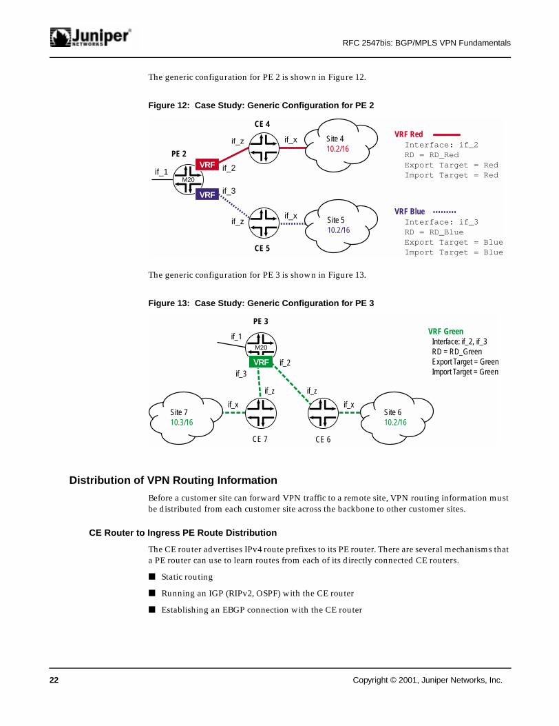
The generic configuration for PE 2 is shown in Figure 12.
Figure 12: Case Study: Generic Configuration for PE 2
The generic configuration for PE 3 is shown in Figure 13.
Figure 13: Case Study: Generic Configuration for PE 3
Distribution of VPN Routing Information
Before a customer site can forward VPN traffic to a remote site, VPN routing information must be distributed from each customer site across the backbone to other customer sites.
CE Router to Ingress PE Route Distribution
The CE router advertises IPv4 route prefixes to its PE router. There are several mechanisms that a PE router can use to learn routes from each of its directly connected CE routers.
■ Static routing
■ Running an IGP (RIPv2, OSPF) with the CE router
■ Establishing an EBGP connection with the CE router
VRF Blue Interface: if_3 RD = RD_Blue Export Target = Blue Import Target = Blue
VRF Red Interface: if_2 RD = RD_Red Export Target = Red Import Target = Red
if_3
if_2if_1
if_x
if_x
if_z
if_z
PE 2
M20
VRF
VRF
Site 510.2/16
CE 5
Site 410.2/16
CE 4
if_1
if_2if_3
VRF Green Interface: if_2, if_3 RD = RD_Green Export Target = Green Import Target = Green
if_x
if_z if_z
if_x
PE 3
M20
VRF
Site 610.2/16
CE 6
Site 710.3/16
CE 7
22 Copyright © 2001, Juniper Networks, Inc.

RFC 2547bis: BGP/MPLS VPN Fundamentals
In the CE-to-ingress PE flow of routing information, the PE router performs a number of functions. It creates and maintains a VRF for each of its directly connected sites. Note that in this example, PE 3 is configured to associate multiple sites (Site 6 and Site 7) with a single VRF.
The PE checks all routes against the locally configured import policy for the routing protocol running between the PE router and the CE router. If the route passes the import policy, the prefix is installed in the VRF as an IPv4 route. The PE must be careful that the routes that it learns from each CE (via an IGP connection) are not leaked into the provider's backbone IGP.
Before advertising a route, the PE assigns an MPLS label to the route.
■ If the route is learned over a point-to-point link, the label is assigned based on the incoming logical interface. In the case of a point-to-point link, all routes are assigned the same label.
■ If the route is learned over a shared media interface such as Fast Ethernet, the label is assigned based on the specific CE router that advertises the prefix. In the case of a shared media interface, all routes learned from a given CE router are assigned the same label while all routes learned from another CE router are assigned a different label.
PE 1
Assume that PE 1 assigns the label 1001 to the routes learned from Site 1, the label 1002 to routes learned from Site 2, and the label 1003 to routes learned from Site 3. PE 1 installs three MPLS routes such that when a packet with a label 1001, 1002, or 1003 is received from the backbone, it can simply pop the label and forward the IPv4 packet directly to CE 1, CE 2, or CE 3 based on the packet's label.
MPLS Forwarding Table (PE 1)
Input OutputInterface Label Action Interface
If_2 1001 Pop if_1If_2 1002 Pop if_4If_2 1003 Pop if_3
As a result of these operations, the VRFs in PE 1 contain the following local routes.
VRF RedBGP Bottom Top
Destination Next-Hop Interface Label Label10.1/16 Direct if_1 1001 -
VRF BlueBGP Bottom Top
Destination Next-Hop Interface Label Label10.1/16 Direct if_4 1002 -
VRF GreenBGP Bottom Top
Destination Next-Hop Interface Label Label10.1/16 Direct if_3 1003 -
PE 2
Assume that PE 2 assigns the label 1004 to routes learned from Site 4, and the label 1005 to routes learned from Site 5. PE 2 installs two MPLS routes such that when a packet with a label 1004 or 1005 is received from the backbone, it can simply pop the label and send the IPv4 packet directly to CE 4 or CE 5 based on the packet's label.
Copyright © 2001, Juniper Networks, Inc. . 23

RFC 2547bis: BGP/MPLS VPN Fundamentals
MPLS Forwarding Table (PE 2)
Input OutputInterface Label Action Interface
If_1 1004 Pop if_2If_1 1005 Pop if_3
As a result of these operations, the VRFs in PE 2 contain the following local routes.
VRF RedBGP Bottom Top
Destination Next-Hop Interface Label Label10.2/16 Direct if_2 1004 -
VRF BlueBGP Bottom Top
Destination Next-Hop Interface Label Label10.2/16 Direct if_3 1005 -
PE 3
Assume that PE 3 assigns the label 1006 to routes learned from Site 6 and the label 1007 to routes learned from Site 7. PE 3 installs two MPLS routes such that when a packet with a label 1006 or 1007 is received from the backbone, it can simply pop the label and forward the IPv4 packet directly to CE 6 or CE 7 based on the packet's label.
MPLS Forwarding Table (PE 3)
Input OutputInterface Label Action Interface
If_1 1006 Pop if_2If_1 1007 Pop if_3
As a result of these operations, the VRF Green in PE 3 contains the following local routes.
VRF GreenBGP Bottom Top
Destination Next-Hop Interface Label Label10.2/16 Direct if_2 1006 -10.3/16 Direct if_3 1007 -
Ingress PE to Egress PE Route Distribution Across Backbone
Ingress PE routers use MP-IBGP to distribute routes received from directly connected sites to egress PE routers. PE routers are required to maintain an MP-IBGP mesh or use route reflectors to ensure that routing information can be distributed to all PE routers.
Before the ingress PE router distributes local VPN routes to its MP-IBGP peers, it converts each IPv4 prefix into a VPN-IPv4 prefix using the RDs configured for the VRF that contains the route. The advertisement for each route contains the following.
■ The VPN-IPv4 address prefix for the route.
■ A BGP next hop that contains the loopback address of the ingress PE router. The address is encoded as a VPN-IPv4 address with a RD = 0 since MP-BGP requires that the next hop be a member of the same address family as the route being advertised.
■ The MPLS label that was assigned to the route by the ingress PE router when it learned the local route from the directly attached CE router.
24 Copyright © 2001, Juniper Networks, Inc.

RFC 2547bis: BGP/MPLS VPN Fundamentals
■ A route target attribute based on the locally configured export target policy for the VRF containing the local route. Recall that all of the PE routers in this example have been configured to assign a route target = Red when advertising VPN Red routes, a route target = Blue when advertising VPN Blue routes, and a route target = Green when advertising VPN Green routes.
■ Optionally, the site-of-origin attribute could be encoded as a route origin extended community.
When an ingress PE router advertises its local VPN-IPv4 routes to its MP-IBGP peers, it can either send all of the routes in its VRFs to all of its MP-IBGP peers or it can construct a distinct advertisement for each peer that excludes the specific VPN routes that it does not share with a given peer. This is accomplished by the use of ORFs that allow a BGP speaker to announce to its peer or route reflector the set of routes that can be imported into one or more VRFs maintained by the PE router.
When an egress PE router receives a VPN-IPv4 route from a peer, it compares the route to all of the VRF import policies for all of the VPNs that are directly attached to the egress PE router. If the route target carried with the route matches the import target policy of at least one of the egress PE's VRFs, the VPN-IPv4 route is installed in its VPN_IPv4.RIB table.
The VPN_IPv4.RIB is a large routing information base (RIB) that contains all routes that satisfy the import policy of at least one of the egress PE router's VRFs. This table is the only one that relies on the RD to disambiguate routes because it is the only table that contains all of the routes from all of the VPNs directly connected to the given PE router. The routes in this table should be globally unique because overlapping IPv4 addresses will have been assigned globally unique RDs.
BGP path selection occurs in this table before routes are exported to their target VRF. Note that user errors when configuring RDs can cause VPN-IPv4 routes in this table to have the same structure when they should be different. If this situation occurs, the BGP path selection is executed and only one of these routes is installed in its VRF. For this reason, RFC 2547bis recommends the use of globally unique public ASNs and IPv4 addresses when a service provider defines its RDs, which is critical if the BGP/MPLS VPN spans multiple service providers. The best route is selected for each VPN-IPv4 prefix and (based on the route target stored with the route) installed in the target VRF as an IPv4 route.
Copyright © 2001, Juniper Networks, Inc. . 25
RFC 2547bis: BGP/MPLS VPN Fundamentals
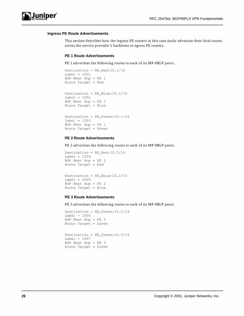
Ingress PE Route Advertisements
This section describes how the ingress PE routers in this case study advertise their local routes across the service provider’s backbone to egress PE routers.
PE 1 Route Advertisements
PE 1 advertises the following routes to each of its MP-IBGP peers.
Destination = RD_Red:10.1/16Label = 1001BGP Next Hop = PE 1Route Target = Red
Destination = RD_Blue:10.1/16Label = 1002BGP Next Hop = PE 1Route Target = Blue
Destination = RD_Green:10.1/16Label = 1003BGP Next Hop = PE 1Route Target = Green
PE 2 Route Advertisements
PE 2 advertises the following routes to each of its MP-IBGP peers.
Destination = RD_Red:10.2/16Label = 1004BGP Next Hop = PE 2Route Target = Red
Destination = RD_Blue:10.2/16Label = 1005BGP Next Hop = PE 2Route Target = Blue
PE 3 Route Advertisements
PE 3 advertises the following routes to each of its MP-IBGP peers.
Destination = RD_Green:10.2/16Label = 1006BGP Next Hop = PE 3Route Target = Green
Destination = RD_Green:10.3/16Label = 1007BGP Next Hop = PE 3Route Target = Green
26 Copyright © 2001, Juniper Networks, Inc.

RFC 2547bis: BGP/MPLS VPN Fundamentals
Egress PE Route Installation
This section describes how the egress PE routers in this case study filter and then install remote routes received from ingress PE routers.
PE 1 Route Installation
PE 1 installs the following route from peer PE 2 into VRF Red.
Destination = RD_Red:10.2/16Label = 1004BGP Next Hop = PE 2Route Target = Red
PE 1 installs the following route from peer PE 2 into VRF Blue.
Destination = RD_Blue:10.2/16Label = 1005BGP Next Hop = PE 2Route Target = Blue
PE 1 installs the following routes from peer PE 3 into VRF Green.
Destination = RD_Green:10.2/16Label = 1006BGP Next Hop = PE 3Route Target = Green
Destination = RD_Green:10.3/16Label = 1007BGP Next Hop = PE 3Route Target = Green
After all routes are exchanged, the contents of PE 1's VRFs are as follows.
VRF RedBGP Bottom Top
Destination Next-Hop Interface Label Label10.1/16 Direct if_1 1001 -10.2/16 PE-2 if_2 1004 11
VRF BlueBGP Bottom Top
Destination Next-Hop Interface Label Label10.1/16 Direct if_4 1002 -10.2/16 PE-2 if_2 1005 11
VRF GreenBGP Bottom Top
Destination Next-Hop Interface Label Label10.1/16 Direct if_3 1003 -10.2/16 PE-3 if_2 1006 1110.3/16 PE-3 if_2 1007 66
Copyright © 2001, Juniper Networks, Inc. . 27

RFC 2547bis: BGP/MPLS VPN Fundamentals
PE 2 Route Installation
PE 2 installs the following route from peer PE 1 into VRF Red.
Destination = RD_Red:10.1/16Label = 1001BGP Next Hop = PE 1Route Target = Red
PE 2 installs the following route from peer PE 1 into VRF Blue.
Destination = RS_Blue:10.1/16Label = 1002BGP Next Hop = PE 1Route Target = Blue
After all routes are exchanged, the contents of PE 2's VRFs are as follows.
VRF RedBGP Bottom Top
Destination Next-Hop Interface Label Label10.1/16 PE-1 if_1 1001 2210.2/16 Direct if_2 1004 -
VRF BlueBGP Bottom Top
Destination Next-Hop Interface Label Label10.1/16 PE 1 if_1 1002 2210.2/16 Direct if_2 1005 -
PE 3 Route Installation
PE 3 installs the following route from peer PE 1 into VRF Green.
Destination = RD_Green:10.1/16Label = 1003BGP Next Hop = PE 1Route Target = Green
After all routes are exchanged, the content of PE 3's VRF is as follows.
VRF GreenBGP Bottom Top
Destination Next-Hop Interface Label Label10.1/16 PE-1 if_1 1003 5510.2/16 Direct if_2 1006 -10.3/16 Direct if_3 1007 -
Egress PE Router to CE Route Distribution
If the egress PE router installs a route in the VRF used to route packets received from a directly connected CE router, the PE router can distribute that route to the CE router. There are several mechanisms that a CE router can use to learn VPN routes from its directly connected PE router.
■ Run an IGP (RIPv2, OSPF) with the PE router.
■ Establish an EBGP connection with the PE router.
Alternatively, the PE router can simply do the following.
■ The PE-to-CE routing protocol can distribute a default route pointing to the PE router.
28 Copyright © 2001, Juniper Networks, Inc.

RFC 2547bis: BGP/MPLS VPN Fundamentals
■ The CE can be configured with a static default route pointing to the PE router.
After all routes are distributed from the egress PE routers to CE routers, the CE routing tables contain the following information.
CE 1 Routing TableDestination Next-Hop Interface10.1/16 Direct if_x10.2/16 PE 1 if_z
CE 2 Routing TableDestination Next-Hop Interface10.1/16 Direct if_x10.2/16 PE 1 if_z
CE 3 Routing TableDestination Next-Hop Interface10.1/16 Direct if_x10.2/16 PE 1 if_z10.3/16 PE 1 if_z
CE 4 Routing TableDestination Next-Hop Interface10.1/16 PE 2 if_z10.2/16 Direct if_x
CE 5 Routing TableDestination Next-Hop Interface10.1/16 PE 2 if_z10.2/16 Direct if_x
CE 6 Routing TableDestination Next-Hop Interface10.1/16 PE 3 if_z10.2/16 Direct if_x10.3/16 PE 3 if_z
CE 7 Routing TableDestination Next-Hop Interface10.1/16 PE 3 if_z10.2/16 PE 3 if_z10.3/16 Direct if_x
Forwarding Customer VPN Traffic Across the BGP/MPLS Backbone
Transmitting customer traffic from one VPN site to another VPN site involves a number of different forwarding decisions.
■ The source CE router to ingress PE router forwarding decision
■ The ingress PE router forwarding decision
■ The forwarding decision at each P router
■ Egress PE router to destination CE router forwarding decision
Copyright © 2001, Juniper Networks, Inc. . 29

RFC 2547bis: BGP/MPLS VPN Fundamentals
Source CE Router to Ingress PE Router Forwarding
When a CE router receives an outbound IPv4 data packet from a system in its site, the CE router performs a traditional longest-match route lookup and forwards the native IPv4 packet to its directly attached PE router.
Ingress PE Router Forwarding
When a PE router receives an IPv4 data packet from a CE router, the PE router performs a route lookup in the VRF for the site based on the packet's incoming subinterface. The packet's destination address is matched against the IPv4 prefix. If a match is found in the VRF, the route lookup returns a next hop and an outgoing subinterface.
If the packet's outgoing subinterface is associated with the same VRF as the incoming packet, the next hop is either another CE device located at the same site or a CE from a different directly connected site that is a member of the same VPN. Recall that a single VRF in a PE router maintains the routes from all directly connected sites of a given VPN.
If the packet's outgoing subinterface and incoming subinterface are associated with two different VRFs, they are directly attached sites that have at least one VPN in common and that each site has a separate forwarding table. To forward the packet, it might be necessary to lookup the packet's destination address in the VRF associated with the outgoing interface.
If the packet's outgoing subinterface is not associated with a VRF, then the packet must travel at least one hop across the provider's backbone to reach a remote PE router. If the packet must cross the provider's backbone then it has two next hops: a BGP next hop and an IGP next hop.
■ The BGP next hop is the ingress PE router that initially advertises the VPN-IPv4 route. The BGP next hop assigns and distributes a label with the route via MP-IBGP that it subsequently uses to identify the directly connected site that advertised the route. The PE router pushes this label onto the packet’s label stack, and it becomes the bottom (or inner) label.
■ The IGP next hop is the first hop in the LPS to the BGP next hop. The IGP next hop will have assigned a label (via LDP or RSVP) for the LSP that leads to the BGP next-hop router. This label is pushed onto the packet's label stack and becomes the top (or outer) label.
For this case, the PE router that receives the packet from the CE and creates the label stack is the ingress LSR, and the BGP next hop is the egress LSR for the LSP across the service provider's network. If the BGP next hop and the IGP next hop are the same routers, and if penultimate hop popping is used, the packet can be transmitted with only the BGP-supplied bottom (or inner) label.
P Router Forwarding
The MPLS backbone switches the labeled packet, swapping the top label at each hop until it reaches the penultimate router to the PE router to which the packet is sent. At the penultimate router, the top label is popped and the packet is sent to the target PE router.
PE Router to Destination CE Router Forwarding
When the PE router receives the packet, it looks for a matching MPLS route (label, subinterface) for the bottom label. If there is a match, the bottom label is popped and a native IPv4 packet is sent directly to the CE router associated with the label. Note that the VRF for the directly connected site does not have to be consulted.
30 Copyright © 2001, Juniper Networks, Inc.

RFC 2547bis: BGP/MPLS VPN Fundamentals
Example #1: Forwarding VPN Red Traffic from Site 1 to Site 4
Assume that Host 10.1.2.3 at Site 1 wants to transmit a packet to Server 10.2.9.3 at Site 4 (Figure 14).
Figure 14: Forwarding VPN Red Traffic from Site 1 to Site 4
When the native IPv4 packet arrives at CE 1, it performs a longest-match route lookup in its IP forwarding table. The entry in CE 1's forwarding table that best matches the packet's destination address is as follows.
Destination Next-Hop Interface10.2/16 PE 1 if_z
As a result of this lookup, CE 1 forwards the native IPv4 packet on if_z to PE 1.
PE 1 receives the native IPv4 packet on if_1. Since all packets that arrive on if_1 are associated with VRF Red, PE 1 performs a longest-match route lookup in VRF Red. The entry in VRF Red that best matches the packet's destination address is as follows.
BGP Bottom TopDestination Next-Hop Interface Label Label10.2/16 PE 2 if_2 1004 11
Since the packet's outgoing subinterface (if_2) is not associated with a local VRF, the packet must travel at least one hop across the provider's MPLS backbone. PE 1 creates an MPLS header for the packet and then pushes the label 1004 (assigned by PE 2 when it originally advertised the route to 10.2/16) onto the packet's label stack, making it the bottom label. PE 1 then pushes the first label (11) for the LSP from PE 1 to PE 2 onto the packet's label stack, making it the top label.
The packet is then forwarded to the first transit router in the LSP from PE 1 to PE 2. The MPLS backbone switches the labeled packet along the LSP, swapping the top label at each hop, until it reaches the penultimate router to PE 2. At the penultimate router, the top label is popped and the packet with a single label (1004) is sent to PE 2.
10.2.9.3 10.2.9.310.2.9.3
100411
10.2.9.3
1004
10.2.9.310.2.9.3
Swap
10.2.9.3
1004
CE 1(Longest- match Lookup)
CE 4(Longest- match Lookup)
PE 2(Pop)
Provider Network
Penultimate(Pop Top)
PE_1(Push 1004 Push 11)
PE 1(Push 1004 Push 11)
Transit LSR(Swap Top)
if_1 if_2 if_1 if_2if_x if_z if_z if_x
11 M40M20 M20M160
VRF
Site 1Host10.1.2.3
Site 4Server10.2.9.3
Copyright © 2001, Juniper Networks, Inc. . 31

RFC 2547bis: BGP/MPLS VPN Fundamentals
When PE 2 receives the labeled packet on if_1, it performs an exact match lookup in its MPLS forwarding table. The entry in the MPLS forwarding table that matches the packet's label is as follows.
Input OutputInterface Label Action Interface
if_1 1004 Pop if_2
As a result of this lookup, PE 2 pops the label and forwards the native IPv4 packet over if_2 to CE 4.
When the native IPv4 packet arrives at CE 4, it performs a longest-match route lookup in its IP forwarding table. The entry in CE 4's forwarding table that best matches the packet's destination address is as follows.
Destination Next-Hop Interface10.2/16 Direct if_x
As a result of this lookup, CE 4 forwards the packet across if_x to Server 10.2.9.3 at Site 4.
Example #2: Forwarding VPN Red Traffic from Site 4 to Site 1
Assume that Server 10.2.9.3 at Site 4 wants to transmit a response packet to Host 10.1.2.3 at Site 1 (Figure 15).
Figure 15: Forwarding VPN Red Traffic from Site 4 to Site 1
When the native IPv4 packet arrives at CE 4, it performs a longest-match route lookup in its IP forwarding table. The entry in CE 4's forwarding table that best matches the packet's destination address is as follows.
Destination Next-Hop Interface10.1/16 PE 2 if_z
As a result of this lookup, CE 4 forwards the native IPv4 packet to PE 2.
10.1.2.3 10.1.2.310.1.2.3
100122
10.1.2.3
1001
10.1.2.310.1.2.3
Swap
10.1.2.3
1001
Provider Network
if_1 if_2 if_1 if_2if_x if_z if_z if_x
M40M20 M20M160
VRF
Site 1Host10.1.2.3
Site 4Server10.2.9.3
CE 1(Longest-match Lookup)
CE 4(Longest-match Lookup)
Penultimate(Pop Top)
PE 2(Push 1001 Push 22)
Transit LSR(Swap Top)
PE 1(Pop)
22
32 Copyright © 2001, Juniper Networks, Inc.

RFC 2547bis: BGP/MPLS VPN Fundamentals
PE 2 receives the native IPv4 packet on if_2. Since all packets that arrive on if_2 are associated with VRF Red, PE 2 performs a longest-match route lookup in VRF Red. The entry in VRF Red that best matches the packet's destination address is as follows.
BGP Bottom TopDestination Next-Hop Interface Label Label10.1/16 PE 1 if_1 1001 22
Since the packet's outgoing subinterface (if_1) is not associated with a local VRF, the packet must travel at least one hop across the provider's MPLS backbone. PE 2 creates an MPLS header for the packet and then pushes the label 1001 (assigned by PE 1 when it originally advertised the route to 10.1/16) onto the packet's label stack, making it the bottom label. PE 2 then pushes the first label (22) for the LSP from PE 2 to PE 1 onto the packet's label stack, making it the top label.
The packet is then forwarded to the first transit router in the LSP from PE 2 to PE 1. The MPLS backbone switches the labeled packet along the LSP, swapping the top label at each hop, until it reaches the penultimate router to PE 1. At the penultimate router, the top label is popped and the packet with a single label (1001) is sent to PE 1.
When PE 1 receives the labeled packet on if_2, it performs an exact match lookup in its MPLS forwarding table. The entry in the MPLS forwarding table that matches the packet's label is as follows.
Input OutputInterface Label Action Interface
if_2 1001 Pop if_1
As a result of this lookup, PE 1 pops the label and forwards the native IPv4 packet over if_1 to CE 1.
When the native IPv4 packet arrives at CE 1, it performs a longest-match route lookup in its IP forwarding table. The entry in CE 1's forwarding table that best matches the packet's destination address is as follows.
Destination Next-Hop Interface10.1/16 Direct if_x
As a result of this lookup, CE 1 forwards the packet across if_x to Host 10.1.2.3 at Site 1.
Example #3: Forwarding VPN Green Traffic from Site 6 to Site 7
Assume that Host 10.2.3.4 at Site 6 wants to transmit a packet to Host 10.3.2.5 at Site 7 (Figure 16).
Copyright © 2001, Juniper Networks, Inc. . 33

RFC 2547bis: BGP/MPLS VPN Fundamentals
Figure 16: Forwarding VPN Red Traffic from Site 6 to Site 7
When the native IPv4 packet arrives at CE 6 on if_x, it performs a longest-match route lookup in its IP forwarding table. The entry in CE 6's forwarding table that best matches the packet's destination address is as follows.
Destination Next-Hop Interface10.3/16 PE 3 if_z
As a result of this lookup, CE 6 forwards the native IPv4 packet across if_z to PE 3.
PE 3 receives the native IPv4 packet on if_2. Since all packets that arrive on if_2 are associated with VRF Green, PE 3 performs a longest-match route lookup in VRF Green. The entry in VRF Green that best matches the packet's destination address is as follows.
BGP Bottom TopDestination Next-Hop Interface Label Label10.3/16 Direct if_3 1008 -
Since the packet's outgoing subinterface is associated with VRF Green, the destination site is directly attached to PE 3, the next hop is a CE router, and the packet does not have to travel across the provider's MPLS backbone. As a result of this lookup, PE 3 forwards the IPv4 packet across if_3 to CE 7.
When the native IPv4 packet arrives at CE 7 on if_z, it performs a longest-match route lookup in its IP forwarding table. The entry in CE 7's forwarding table that best matches the packet's destination address is as follows.
Destination Next-Hop Interface10.3/16 Direct if_x
As a result of this lookup, CE 7 forwards the packet across if_x to Host 10.3.2.5 at Site 7.
if_1
if_2if_3
if_x if_z if_z if_x
PE 3
M20
VRF
Site 6Host10.2.3.4
CE 6
Site 7Host10.3.2.5
CE 7
10.3
.2.5
10.3.2.5
34 Copyright © 2001, Juniper Networks, Inc.

RFC 2547bis: BGP/MPLS VPN Fundamentals
Accessing the Public Internet from a VPN Site
Many hosts at VPN sites need to access the public Internet, as well as other VPN sites. In many cases, the private network can use the private IP address space. Generally, there are three ways that a host in the VPN can obtain a globally unique address to communicate with hosts on the public Internet.
■ All systems in the private network can use globally unique IP addresses.
■ If only a small number of systems in the private network access the public Internet, those few systems can be given globally unique Internet addresses. It is common for systems in a private network to use private IP addresses at the same time that a few systems in the same private network are using public IP addresses.
■ A Network Address Translator (NAT) server within the private network can be used to allow systems in the VPN that are assigned private IP addresses to access the public Internet.
There are a number of approaches within the BGP/MPLS VPN model that can be used to achieve this goal. One such way is the non-VRF Internet access mechanism.
Non-VRF Internet Access
Typically, one or more customer VPN sites can provide direct Internet access to a service provider through an Internet gateway. The service provider might or might not be the same service provider that delivers the VPN service. Also, the Internet gateway service can run on a non-VRF interface of a CE router or on another router at the customer site. The router interface that delivers Internet access is configured to function as an Internet firewall and a NAT. In Figure 17, Internet access for VPN Red is provided by a non-VRF interface on CE 1.
Figure 17: Non-VRF Internet Access
VRFNAT
VRF VRFNAT
Site 1Red VPN
Site 2Red VPN
Site 3Red VPN
CE 3PE 1 VPN Provider
DefaultRoute
Default Route
InternetAccess Provider
Non-VRFInterface
Globally UniqueIP Prefix
CE 2
DefaultRoute
PE 2
CE 1 DefaultRoute
Copyright © 2001, Juniper Networks, Inc. . 35

RFC 2547bis: BGP/MPLS VPN Fundamentals
VPN Hosts to Public Internet
To allow hosts at VPN Red sites to access the public Internet, CE 1 at Site 1 distributes the default route to PE 1, which installs it in VRF Red (Figure 17). PE 1 then distributes the default route by way of MP-IBGP to PE 2, which installs it into VRF Red. Finally, PE 2 distributes the default route to CE 2 at Site 2 and CE 3 at Site 3. As a result of this announcement, hosts at any VPN Red site forward public Internet traffic to CE 1 at Site 1, which routes the traffic out its NAT interface to the public Internet. The NAT service translates each private source address to public source address.
Public Internet to VPN Hosts
To allow hosts or servers in the public Internet to respond to hosts at VPN Red sites, CE 1 advertises a public IP prefix into the Internet routing table (Figure 17). Routers in the Internet forward traffic to CE 1 based on this public prefix. When a packet arrives on CE 1’s NAT interface, the NAT service translates the public destination address back to a private destination address. If the destination host is located at Site 1, CE 1 simply forwards the packet directly to the host. If the destination host is located at Site 2 or Site 3, CE 1 forwards the packet to PE 1, which in turn, forwards the packet to PE 2.
While sites without direct Internet access are required to use a VRF interface to access the public Internet, all packets entering or leaving the VPN must eventually traverse a non-VRF/NAT interface at the site that provides direct Internet access.
Scalability of BGP/MPLS VPNs
This section provides a brief summary of the architectural elements that RFC 2547bis defines to enhance the scalability of BGP/MPLS VPNs.
■ BGP/MPLS VPNs are not constructed as an overlay network that sits on top of the service provider's network. Hence, the n-squared scalability issues typically associated with the overlay model do not exist.
■ If there are multiple attachments between a customer site and a PE router, all of the attachments are mapped to a single forwarding table to conserve PE router resources.
■ Overlapping address spaces are supported, thus allowing customers to efficiently use the private IP address space.
■ PE routers are required to maintain VPN routes, but only for those VPNs to which they are directly attached.
■ Route targets constrain the distribution of routing information.
■ PE routers do not maintain routes to remote CE routers, only to other PE routers.
■ P routers do not maintain any VPN routing information due to the use of a two-level label stack.
■ No single system in the provider's backbone is required to maintain routing information for all of the VPNs supported by the service provider.
■ Network management is simplified because service providers do not have a backbone or virtual backbone to administer for each customer VPN.
■ RDs are structured to ensure that every service provider can administer its own numbering space and create globally unique RDs that do not conflict with the RDs assigned by any other service provider.
36 Copyright © 2001, Juniper Networks, Inc.

RFC 2547bis: BGP/MPLS VPN Fundamentals
■ ORFs reduce the amount of routing information distributed across the provider's backbone and conserve PE router packet processing resources.
■ The challenge of maintaining a full mesh of MP-IBGP connections is eliminated through the use of route reflectors.
■ Route reflectors are the only systems in the network that are required to maintain VPN routing information for sites to which they are not directly connected. Segmented route reflection enhances scalability because no single route reflector has to maintain routing information for all VPN-IPv4 routes deployed across the provider’s network.
■ RSVP-based traffic engineered LSPs optimize connectivity between PE routers.
■ The public Internet can be accessed without requiring that Internet routes be replicated into VRFs.
Conclusion
Though the operational details described in RFC 2547bis VPNs are appropriate for a large number of customer applications, they cannot meet all customers’ end-user requirements and business objectives.
A BGP/MPLS VPN is well suited for customers that have relatively simple networks. It allows customers to outsource the complexity of routing management to their VPN service provider, shifts the complexities of managing full-mesh inter-site connectivity from the subscriber CPE router to the PE router where it can be piggybacked over the provider’s IBGP, and allows providers to use a shared MPLS infrastructure to transport both private and public data traffic.
However, the BGP/MPLS VPN approach is not without its limitations.
■ It might have difficulty handling complex routing situations because it is based on a relatively simple routing relationship between CE and PE routers.
■ The management of potentially hundreds of forwarding tables in a single PE router is not well understood.
■ There is no support for IP Multicast.
■ Multiprovider environments present a number of formidable problems when trying to support end-to-end class of service or QoS.
■ The interworking of network management and other operational support tools becomes extremely complex in multiprovider environments.
All VPN architectures have a number of benefits and limitations. Service providers should perform a careful analysis of customer requirements and then select the best solution for each customer from a portfolio of VPN service delivery models. BGP/MPLS VPNs is likely to play a central role in any set of VPN service models offered.
Copyright © 2001, Juniper Networks, Inc. . 37

RFC 2547bis: BGP/MPLS VPN Fundamentals
References
Internet Drafts
Chen and Rekhter, Cooperative Route Filtering Capability for BGP4, <draft-ietf-idr-route-filter-02.txt>, November 2000.
Ramachandra, Tappan, and Rekhter, BGP Extended Communities Attribute, <draft-ramachandra-bgp-ext-communities-08.txt>, January 2001.
Rosen, Rekhter, Bogovic, Brannon, Carugi, Chase, Chung, Dean, De Clercq, Hitchen, Leelanivas, Marshall, Martini, Morrow, Vaidyanathan, Smith, Srinivasan, and Vedrenne, BGP/MPLS VPNs, <draft-rosen-rfc2547bis-02.txt>, July 2000.
Requests for Comments
RFC 1771, A Border Gateway Protocol 4 (BGP4), Rekhter and Li, March 1995.
RFC 1997, BGP Communities Attribute, Chandra, Traina, and Li, August 1996.
RFC 2283, Multiprotocol Extensions for BGP4, Bates, Chandra, Katz, and Rekhter, February 1998.
RFC 2547, BGP/MPLS VPNs, Rosen and Rekhter, March 1999.
RFC 2796, BGP Route Reflection: An Alternative to Full Mesh IBGP, Bates, Chandra, and Chen, April 2000.
RFC 2842, Capabilities Advertisement with BGP4, Chandra, and Scudder, May 2000.
RFC 2858, Multiprotocol Extensions for BGP4, Bates, Chandra, Katz, and Rekhter, June 2000.
RFC 2918, Route Refresh Capability for BGP4, Chen, September 2000.
Textbooks
Davie, Bruce S. and Yakov Rekhter, MPLS: Technology and Applications, Morgan Kaufmann Publishers, San Francisco, 2000, (ISBN 1-55860-656-4-4).
Huston, Geoff, ISP Survival Guide: Strategies for Running a Competitive ISP, John Wiley & Sons Inc., New York, 1999, (ISBN 0-471-31499-4).
Scott, Charles, Paul Wolfe, and Mike Erwin, Virtual Private Networks (Second Edition), O’Reilly & Associates, Inc., California 1999, (ISBN 1-56592-527-7).
Copyright © 2001, Juniper Networks, Inc. All rights reserved. Juniper Networks is a registered trademark of Juniper Networks, Inc. Internet Processor, Internet Processor II, JUNOS, JUNOScript, M5, M10, M20, M40, and M160 are trademarks of Juniper Networks, Inc. All other trademarks, service marks, registered trademarks, or registered service marks may be the property of their respective owners. All specifications are subject to change without notice. Printed in USA.
38 Copyright © 2001, Juniper Networks, Inc.