Embed Size (px)
Citation preview
Review of Federal Motor Vehicle Safety Standards (FMVSS) for Automated Vehicles Identifying potential barriers and challenges for the
certification of automated vehicles using existing FMVSS
Preliminary Report – March 2016
Anita Kim, David Perlman, Dan Bogard and Ryan Harrington Technology Innovation and Policy Division
Prepared for:
Intelligent Transportation Systems Joint Program Office (ITS JPO) National Highway Traffic Safety Administration (NHTSA) U.S. Department of Transportation 1200 New Jersey Avenue, S.E. Washington, DC 20590
Review of Federal Motor Vehicle Safety Standards i
Notice This document is disseminated under the sponsorship of the United States Department of
Transportation in the interest of information exchange. The United States Government assumes
no liability for the contents or use thereof.
The United States Government does not endorse products or manufacturers. Trade or
manufacturers’ names appear herein solely because they are considered essential to the
objective of this report.
Review of Federal Motor Vehicle Safety Standards ii
REPORT DOCUMENTATION PAGE Form Approved OMB No. 0704-0188
Public reporting burden for this collection of information is estimated to average 1 hour per response, including the time for reviewing instructions, searching existing data sources, gathering and maintaining the data needed, and completing and reviewing the collection of information. Send comments regarding this burden estimate or any other aspect of this collection of information, including suggestions for reducing this burden, to Washington Headquarters Services, Directorate for Information Operations and Reports, 1215 Jefferson Davis Highway, Suite 1204, Arlington, VA 22202-4302, and to the Office of Management and Budget, Paperwork Reduction Project (0704-0188), Washington, DC 20503.
1. AGENCY USE ONLY (Leave blank)
2. REPORT DATE
March 2016
3. REPORT TYPE AND DATES COVERED
Preliminary report, August 2015 -
March 2016
4. TITLE AND SUBTITLE
Review of Federal Motor Vehicle Safety Standards (FMVSS) for Automated Vehicles: Identifying potential barriers and challenges for the certification of automated vehicles using existing FMVSS
5a. FUNDING NUMBERS
Inter-Agency Agreement DTFH61-13-
V-0020 HW56A1
6. AUTHOR(S)
Anita Kim, Dan Bogard, David Perlman, Ryan Harrington
5b. CONTRACT NUMBER
7. PERFORMING ORGANIZATION NAME(S) AND ADDRESS(ES)
U.S. Department of Transportation John A. Volpe National Transportation Systems Center, Technology Innovation and Policy Division 55 Broadway, Cambridge, MA 02142
8. PERFORMING ORGANIZATION REPORT
NUMBER
DOT-VNTSC-OSTR-16-03
9. SPONSORING/MONITORING AGENCY NAME(S) AND ADDRESS(ES)
U.S. Department of Transportation Intelligent Transportation Systems Joint Program Office and National Highway Traffic Safety Administration 1200 New Jersey Ave, SE Washington, DC 20590
10. SPONSORING/MONITORING
AGENCY REPORT NUMBER
11. SUPPLEMENTARY NOTES
The agreement Officers Representative for this study was Kevin Dopart, Vehicle Safety and Automation Manager at ITS JPO.
12a. DISTRIBUTION/AVAILABILITY STATEMENT
This document is available to the public at the Volpe website
12b. DISTRIBUTION CODE
13. ABSTRACT (Maximum 200 words)
The purpose of this work is to identify instances where the existing Federal Motor Vehicle Safety Standards may pose challenges to the introduction of automated vehicles. It identifies standards requiring further review - both to ensure that existing regulations do not unduly stifle innovation and to help ensure that automated vehicles perform their functions safely. The Volpe team conducted two reviews of the FMVSS: a driver reference scan to identify which standards include an explicit or implicit reference to a human driver and an automated vehicle concepts scan to identify which standards could pose a challenge for a wide range of automated vehicle capabilities and concepts. In summary, the review revealed that there are few barriers for automated vehicles to comply with FMVSS, as long as the vehicle does not significantly diverge from a conventional vehicle design. Yet, automated vehicles that begin to push the boundaries of conventional design (e.g. alternative cabin layouts, omission of manual controls) would be constrained by the current FMVSS or may not fully meet the objectives of the FMVSS. Many standards, as currently written, are based on assumptions of conventional vehicle designs and thus pose challenges for certain design concepts, particularly for ‘driverless’ concepts where human occupants have no way of driving the vehicle. Some constraints, of course, may be warranted; this work does not assess the merits of potential future requirements for such vehicles.
14. SUBJECT TERMS
Automated vehicles, autonomous vehicles, Federal Motor Vehicle Safety Standards, motor vehicles, regulation, standards
15. NUMBER OF PAGES
16. PRICE CODE
17. SECURITY CLASSIFICATION
OF REPORT
Unclassified
18. SECURITY CLASSIFICATION
OF THIS PAGE
Unclassified
19. SECURITY CLASSIFICATION
OF ABSTRACT
Unclassified
20. LIMITATION OF ABSTRACT
Unlimited
NSN 7540-01-280-5500 Standard Form 298 (Rev. 2-89) Prescribed by ANSI Std. 239-18
298-102
Review of Federal Motor Vehicle Safety Standards iii
Acknowledgments
The U.S. Department of Transportation John A. Volpe National Transportation Systems Center (Volpe
Center), in Cambridge, Massachusetts, prepared this report for the U.S. Department of Transportation
Intelligent Transportation Systems Joint Program Office (ITS JPO). The project team consisted of Anita
Kim, David Perlman, Dan Bogard and Ryan Harrington of Volpe’s Technology Innovation and Policy
division. Kevin Dopart of the ITS JPO provided project oversight.
This project was funded by the ITS JPO and conducted in coordination with the National Highway Traffic
Safety Administration (NHTSA). It benefited significantly from insights and comments offered by
representatives from the NHTSA Office of Chief Counsel and Office of Vehicle Safety Research. In
particular, the project team would like to thank Rebecca Yoon, Tim Johnson, Jesse Chang, and Cem
Hatipoglu, for their valuable technical insight and guidance.
Review of Federal Motor Vehicle Safety Standards iv
Contents
List of Tables ......................................................................................................................... v
List of Abbreviations ............................................................................................................. vii
Executive Summary ............................................................................................................. viii
Introduction ................................................................................................................... 1 1.
FMVSS Scan Approach .................................................................................................... 3 2.
2.1 Overview ..................................................................................................................................... 3
2.2 Driver Reference Categories ....................................................................................................... 3
2.3 Vehicle Concept Descriptions ..................................................................................................... 4
Summary of Findings ...................................................................................................... 8 3.
3.1 Driver Reference Scan ................................................................................................................. 8
3.2 Automated Vehicle Concepts Scan ............................................................................................. 9
3.2.1 Conventional Vehicle Concepts ..................................................................................... 9
3.2.2 Advanced Concepts ...................................................................................................... 10
3.2.3 Low-Speed Vehicles ..................................................................................................... 11
3.2.4 Aftermarket Systems ................................................................................................... 11
3.2.5 FMVSS Definitions ........................................................................................................ 12
3.3 Table Summaries of Standards by Series .................................................................................. 12
3.3.1 Driver References and AV Issues by Standard, 100 series ........................................... 14
3.3.3 Driver References and AV Issues by Standard, 200 series ........................................... 17
3.3.4 Driver References and AV Issues by Standard, 300-500 series.................................... 19
Summary and Areas for Further Discussion ................................................................... 20 4.
Appendix A: Automated Vehicle Concept Descriptions ......................................................... 22
Appendix B: Reference Language – Excerpts from FMVSS ..................................................... 26
Review of Federal Motor Vehicle Safety Standards v
List of Tables
Table 1 Driver Reference Categories and Descriptions ................................................................................ 3
Table 2 Automated Vehicle Concepts by Category ....................................................................................... 7
Table 3 Summary of Driver Reference Scan and Advanced Vehicle Concepts Scan, 100 Series ................ 14
Table 4 Summary of Driver Reference Scan and Advanced Vehicle Concepts Scan, 200 Series ................ 17
Table 5 Summary of Driver Reference Scan and Advanced Vehicle Concepts Scan, 300-500 series ......... 19
Table 6 Types of Conflicts and Numerical Identifier ................................................................................... 26
Table 7 Overview of Concepts with Standard 101; Controls and Displays. ................................................ 32
Table 8 Overview of Concepts with Standard 102; Transmission Shift Position Sequence, Starter
Interlock, and Transmission Braking Effect. ................................................................................... 36
Table 9 Overview of Concepts with Standard 103; Windshield Defrosting and Defogging Systems. ........ 38
Table 10 Overview of Concepts with Standard 104; Windshield Wiping and Washing Systems. .............. 39
Table 11 Overview of Concepts with Standard 105; Hydraulic and Electric Brake Systems. ..................... 40
Table 12 Overview of Concepts with Standard 108; Lamps, Reflective Devices, and Associated
Equipment. ..................................................................................................................................... 45
Table 13 Overview of Concepts with Standard 110; Tire Selection and Rims and Motor Home/Recreation
Vehicle Trailer Load Carrying Capacity Information for Motor Vehicles with a GVWR of 4,536
kilograms (10,000 pounds) or less. ................................................................................................ 50
Table 14 Overview of Concepts with Standard 111; Rear Visibility. ........................................................... 51
Table 15 Overview of Concepts with Standard 113; Hood Latch System. .................................................. 59
Table 16 Overview of Concepts with Standard 114; Theft Protection and Rollaway Prevention. ............. 60
Table 17 Overview of Concepts with Standard 118; Power-operated Window, Partition, and Roof Panel
Systems. ......................................................................................................................................... 63
Table 18 Overview of Concepts with Standard 121; Air Brake Systems. .................................................... 64
Table 19 Overview of Concepts with Standard 122; Motorcycle Brake Systems. ...................................... 67
Table 20 Overview of Concepts with Standard 122; Motorcycle Brake Systems. ...................................... 76
Table 21 Overview of Concepts with Standard 123; Motorcycle Controls and Displays. ........................... 77
Table 22 Overview of Concepts with Standard 124; Accelerator Control Systems. ................................... 79
Table 23 Overview of Concepts with Standard 125; Warning Devices. ...................................................... 80
Table 24 Overview of Concepts with Standard 126; Electronic Stability Control Systems for Light Vehicles.
....................................................................................................................................................... 81
Review of Federal Motor Vehicle Safety Standards vi
Table 25 Overview of Concepts with Standard 131; School Bus Pedestrian Safety Devices. ..................... 87
Table 27 Overview of Concepts with Standard 135; Light Vehicle Brake Systems. .................................... 88
Table 27 Overview of Concepts with Standard 138; Tire Pressure Monitoring Systems. .......................... 97
Table 28 Overview of Concepts with Standard 201; Occupant Protection in Interior Impact. ................ 100
Table 29 Overview of Concepts with Standard 202a; Head Restraints; Mandatory Applicability Begins of
September 1, 2009. ...................................................................................................................... 102
Table 30 Overview of Concepts with Standard 203; Impact Protection for the Driver from the Steering
Control System. ............................................................................................................................ 103
Table 31 Overview of Concepts with Standard 204; Steering Control Rearward Displacement. ............. 104
Table 32 Overview of Concepts with Standard 205; Glazing Materials. ................................................... 105
Table 33 Overview of Concepts with Standard 206; Door Locks and Door Retention Components. ...... 106
Table 34 Overview of Concepts with Standard 207; Seating Systems. ..................................................... 108
Table 35 Overview of Concepts with Standard 208; Occupant Crash Protection. ................................... 109
Table 36 Overview of Concepts with Standard 210; Seat Belt Assembly Anchorages. ............................ 120
Table 37 Overview of Concepts with Standard 214; Side Impact Protection. .......................................... 121
Table 38 Overview of Concepts with Standard 216; Roof Crush Resistance. ........................................... 127
Table 39 Overview of Concepts with Standard 216a; Roof Crush Resistance; Upgraded Standard. ....... 128
Table 40 Overview of Concepts with Standard 219; Windshield Zone Intrusion. .................................... 129
Table 41 Overview of Concepts with Standard 222; School Bus Passenger Seating and Crash Protection.
..................................................................................................................................................... 130
Table 42 Overview of Concepts with Standard 225; Child Restraint Anchorage Systems. ...................... 131
Table 43 Overview of Concepts with Standard 226; Ejection Mitigation. ................................................ 132
Table 44 Overview of Concepts with Standard 302; Flammability of Interior Materials. ........................ 133
Table 45 Overview of Concepts with Standard 401; Interior Trunk Release. ........................................... 134
Table 46 Overview of Concepts with Standard 500; Low-Speed Vehicles. ............................................... 135
Review of Federal Motor Vehicle Safety Standards vii
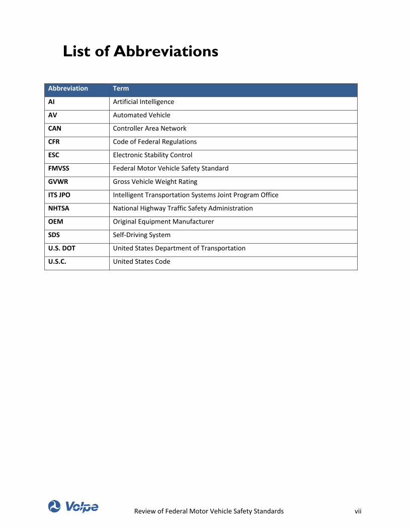
List of Abbreviations
Abbreviation Term
AI Artificial Intelligence
AV Automated Vehicle
CAN Controller Area Network
CFR Code of Federal Regulations
ESC Electronic Stability Control
FMVSS Federal Motor Vehicle Safety Standard
GVWR Gross Vehicle Weight Rating
ITS JPO Intelligent Transportation Systems Joint Program Office
NHTSA National Highway Traffic Safety Administration
OEM Original Equipment Manufacturer
SDS Self-Driving System
U.S. DOT United States Department of Transportation
U.S.C. United States Code
Review of Federal Motor Vehicle Safety Standards viii
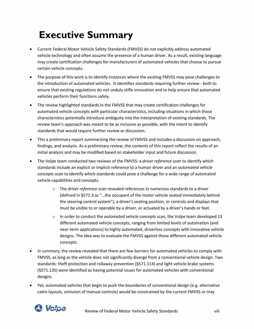
Executive Summary
Current Federal Motor Vehicle Safety Standards (FMVSS) do not explicitly address automated
vehicle technology and often assume the presence of a human driver. As a result, existing language
may create certification challenges for manufacturers of automated vehicles that choose to pursue
certain vehicle concepts.
The purpose of this work is to identify instances where the existing FMVSS may pose challenges to
the introduction of automated vehicles. It identifies standards requiring further review - both to
ensure that existing regulations do not unduly stifle innovation and to help ensure that automated
vehicles perform their functions safely.
The review highlighted standards in the FMVSS that may create certification challenges for
automated vehicle concepts with particular characteristics, including situations in which those
characteristics potentially introduce ambiguity into the interpretation of existing standards. The
review team’s approach was meant to be as inclusive as possible, with the intent to identify
standards that would require further review or discussion.
This a preliminary report summarizing the review of FMVSS and includes a discussion on approach,
findings, and analysis. As a preliminary review, the contents of this report reflect the results of an
initial analysis and may be modified based on stakeholder input and future discussion.
The Volpe team conducted two reviews of the FMVSS: a driver reference scan to identify which
standards include an explicit or implicit reference to a human driver and an automated vehicle
concepts scan to identify which standards could pose a challenge for a wide range of automated
vehicle capabilities and concepts.
o The driver reference scan revealed references in numerous standards to a driver
(defined in §571.3 as “…the occupant of the motor vehicle seated immediately behind
the steering control system”), a driver’s seating position, or controls and displays that
must be visible to or operable by a driver, or actuated by a driver’s hands or feet.
o In order to conduct the automated vehicle concepts scan, the Volpe team developed 13
different automated vehicle concepts, ranging from limited levels of automation (and
near-term applications) to highly automated, driverless concepts with innovative vehicle
designs. The idea was to evaluate the FMVSS against these different automated vehicle
concepts.
In summary, the review revealed that there are few barriers for automated vehicles to comply with
FMVSS, as long as the vehicle does not significantly diverge from a conventional vehicle design. Two
standards: theft protection and rollaway prevention (§571.114) and light vehicle brake systems
(§571.135) were identified as having potential issues for automated vehicles with conventional
designs.
Yet, automated vehicles that begin to push the boundaries of conventional design (e.g. alternative
cabin layouts, omission of manual controls) would be constrained by the current FMVSS or may
Review of Federal Motor Vehicle Safety Standards ix
conflict with policy objectives of the FMVSS. Many standards, as currently written, are based on
assumptions of conventional vehicle designs and thus pose challenges for certain design concepts,
particularly for ‘driverless’ concepts where human occupants have no way of driving the vehicle (e.g.
§571.101, controls and displays, §571.111, rear visibility, §571.208, occupant crash protection
represent a few examples).
Subsequent to the Volpe Center’s review of the FMVSS, but prior to the publication of this report,
NHTSA released interpretations to BMW of North America and Google, Inc. in response to questions
about how to interpret certain FMVSS requirements in the context of automated vehicles. The full
text of these interpretations are available in NHTSA’s repository of interpretation files at the
website: isearch.nhtsa.gov.
Review of Federal Motor Vehicle Safety Standards 1
Introduction 1.
In order to sell a motor vehicle in the U.S. market, a vehicle manufacturer must certify that the vehicle
meets performance requirements specified in the Federal Motor Vehicle Safety Standards, or FMVSS.1
The FMVSS are codified at 49 C.F.R. Part 571, and encompass 73 separate standards that generally focus
on crash avoidance, crashworthiness, and post-crash survivability. Various safety standards apply to
different vehicle types, including motorcycles, low-speed vehicles,2 passenger cars, multipurpose
passenger vehicles (such as vans and sport-utility vehicles), trucks, trailers, and buses (including school
buses).
First introduced through the National Traffic and Motor Vehicle Safety Act of 1966, the FMVSS have
generally developed with the assumption that vehicles subject to them would be driven by a human
driver. However, the pace of advancement in automated vehicle technology over the last ten years
suggests a need to consider how automated vehicles, in which both the vehicle and the human may
share in the driving task (or the vehicle itself is the only driver) might fit into the regulatory context of
FMVSS. Though significant uncertainty still exists around when commercially-viable automated vehicles
will become available, the extent of industry activity indicates that commercialization of automated
vehicles – at least in limited form – is imminent.
In light of this expectation that automated vehicles in some form may be production-ready in the near
future, the United States Department of Transportation (U.S. DOT) Volpe Center, in support of the
Intelligent Transportation Systems (ITS) Joint Program Office’s (JPO) Automated Vehicle Program and in
coordination with the National Highway Traffic Safety Administration (NHTSA), recently completed a
review of the FMVSS to understand how the existing standards might create certification challenges for
manufacturers producing increasingly automated vehicle technologies. This review focused on
identifying FMVSS sections where the mechanism(s) by which certain automated vehicle designs would
certify compliance are unclear or prohibitive.
The Volpe team conducted two full reviews of the FMVSS. The first review identified explicit and implicit
references to a human driver contained in the FMVSS. The second review was much broader and
inclusive; reviewers assessed whether and to what extent the FMVSS might make it difficult to certify
the compliance of an automated vehicle. This later review evaluated how the FMVSS language could
become challenging, especially as industry moves towards higher levels of automation, including new
vehicle concepts and designs.
In summary, the Volpe Center’s review revealed a few barriers in the FMVSS to the certification of an
automated vehicle that conforms to conventional vehicle design practices. These barriers could pose
challenges to the certification of automated vehicles in the near future if not revised. However,
1 49 U.S.C. 30115.
2 §571.3 defines low-speed vehicles as four-wheeled vehicles having a GVWR of no more than 3,000 pounds and capable of
achieving no more than 25 miles per hour
Review of Federal Motor Vehicle Safety Standards 2
advanced automated vehicle designs that attempt to take advantage of the opportunities presented by
full automation (e.g., reconfigured cabin layouts and omission of manual control, if the vehicle literally
cannot be driven by a human occupant) may face significant challenges to certification under the
existing standards.
This report documents the Volpe Center’s approach and findings through its review of the FMVSS to
identify potential challenges with certifying a range of automated vehicles concepts. The document also
includes an appendix that captures all the FMVSS language identified for further review.
Review of Federal Motor Vehicle Safety Standards 3
FMVSS Scan Approach 2.
2.1 Overview
The Volpe Center team reviewed the entirety of the FMVSS (contained in 49 CFR Part 571; using version
of FMVSS downloaded from http://www.ecfr.gov/ on August 10, 2015) in two phases or scans – a “driver
reference scan” and an “automated vehicle concepts scan.”
The Driver Reference Scan (primary scan) identified both explicit and implicit references to a human
driver. The reviewers flagged each standard that includes a driver reference or assumption of a driver.
The driver references were categorized by reference types and are summarized in Section 2.2 below.
The Automated Vehicle Concepts Scan (advanced scan) determined if a portfolio of automated vehicle
concepts (described in Section 2.3), ranging from likely near-term features to advanced yet plausible
“driverless” concepts, could likely be certified under the current FMVSS. The advanced scan assessed
how existing FMVSS may pose challenges for the spectrum of automated capabilities and vehicle
concepts that could emerge in the future.
2.2 Driver Reference Categories
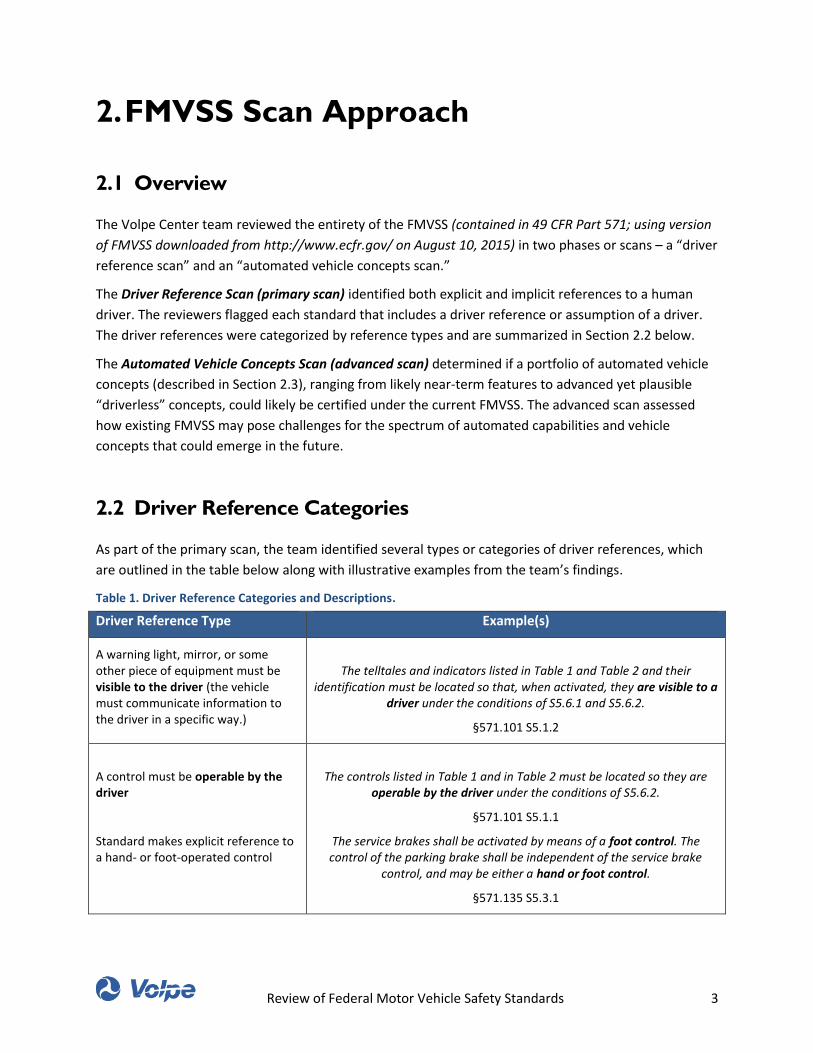
As part of the primary scan, the team identified several types or categories of driver references, which
are outlined in the table below along with illustrative examples from the team’s findings.
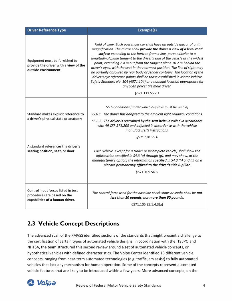
Table 1. Driver Reference Categories and Descriptions.
Driver Reference Type Example(s)
A warning light, mirror, or some other piece of equipment must be visible to the driver (the vehicle must communicate information to the driver in a specific way.)
The telltales and indicators listed in Table 1 and Table 2 and their identification must be located so that, when activated, they are visible to a
driver under the conditions of S5.6.1 and S5.6.2.
§571.101 S5.1.2
A control must be operable by the driver
Standard makes explicit reference to a hand- or foot-operated control
The controls listed in Table 1 and in Table 2 must be located so they are operable by the driver under the conditions of S5.6.2.
§571.101 S5.1.1
The service brakes shall be activated by means of a foot control. The control of the parking brake shall be independent of the service brake
control, and may be either a hand or foot control.
§571.135 S5.3.1
Review of Federal Motor Vehicle Safety Standards 4
Driver Reference Type Example(s)
Equipment must be furnished to provide the driver with a view of the outside environment
Field of view. Each passenger car shall have an outside mirror of unit magnification. The mirror shall provide the driver a view of a level road
surface extending to the horizon from a line, perpendicular to a longitudinal plane tangent to the driver's side of the vehicle at the widest
point, extending 2.4 m out from the tangent plane 10.7 m behind the driver's eyes, with the seat in the rearmost position. The line of sight may be partially obscured by rear body or fender contours. The location of the driver's eye reference points shall be those established in Motor Vehicle
Safety Standard No. 104 (§571.104) or a nominal location appropriate for any 95th percentile male driver.
§571.111 S5.2.1
Standard makes explicit reference to a driver’s physical state or anatomy
A standard references the driver’s seating position, seat, or door
S5.6 Conditions [under which displays must be visible]
S5.6.1 The driver has adapted to the ambient light roadway conditions.
S5.6.2 The driver is restrained by the seat belts installed in accordance with 49 CFR 571.208 and adjusted in accordance with the vehicle
manufacturer's instructions.
§571.101 S5.6
Each vehicle, except for a trailer or incomplete vehicle, shall show the information specified in S4.3 (a) through (g), and may show, at the
manufacturer's option, the information specified in S4.3 (h) and (i), on a placard permanently affixed to the driver's side B-pillar.
§571.109 S4.3
Control input forces listed in test procedures are based on the capabilities of a human driver.
The control force used for the baseline check stops or snubs shall be not less than 10 pounds, nor more than 60 pounds.
§571.105 S5.1.4.3(a)
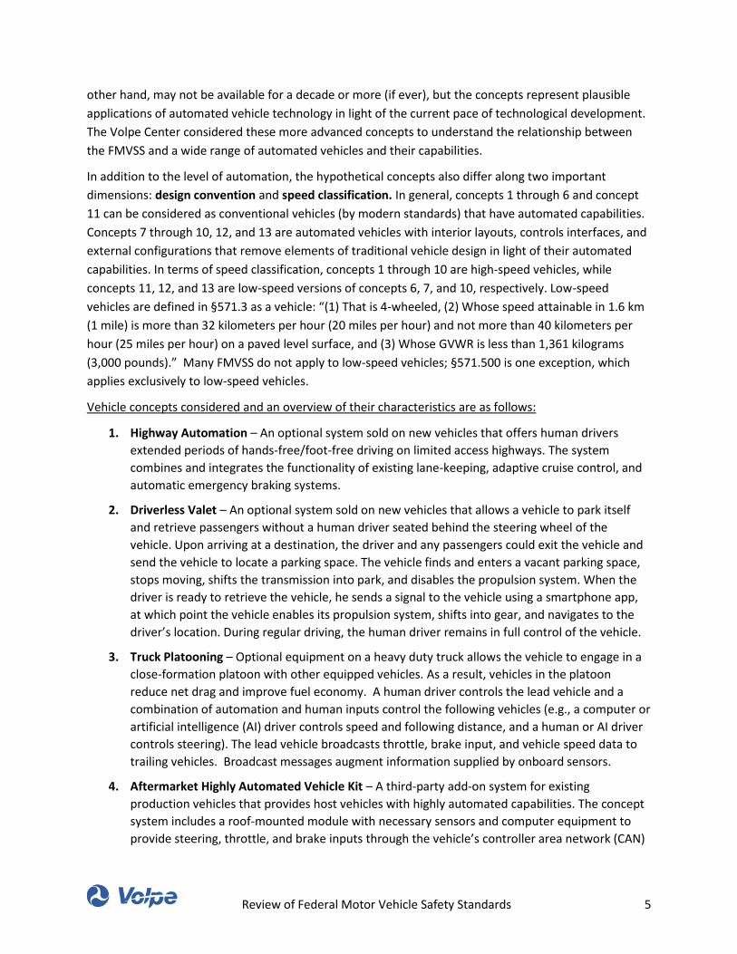
2.3 Vehicle Concept Descriptions
The advanced scan of the FMVSS identified sections of the standards that might present a challenge to
the certification of certain types of automated vehicle designs. In coordination with the ITS JPO and
NHTSA, the team structured this second review around a set of automated vehicle concepts, or
hypothetical vehicles with defined characteristics. The Volpe Center identified 13 different vehicle
concepts, ranging from near-term automated technologies (e.g. traffic jam assist) to fully automated
vehicles that lack any mechanism for human operation. Some of the concepts represent automated
vehicle features that are likely to be introduced within a few years. More advanced concepts, on the
Review of Federal Motor Vehicle Safety Standards 5
other hand, may not be available for a decade or more (if ever), but the concepts represent plausible
applications of automated vehicle technology in light of the current pace of technological development.
The Volpe Center considered these more advanced concepts to understand the relationship between
the FMVSS and a wide range of automated vehicles and their capabilities.
In addition to the level of automation, the hypothetical concepts also differ along two important
dimensions: design convention and speed classification. In general, concepts 1 through 6 and concept
11 can be considered as conventional vehicles (by modern standards) that have automated capabilities.
Concepts 7 through 10, 12, and 13 are automated vehicles with interior layouts, controls interfaces, and
external configurations that remove elements of traditional vehicle design in light of their automated
capabilities. In terms of speed classification, concepts 1 through 10 are high-speed vehicles, while
concepts 11, 12, and 13 are low-speed versions of concepts 6, 7, and 10, respectively. Low-speed
vehicles are defined in §571.3 as a vehicle: “(1) That is 4-wheeled, (2) Whose speed attainable in 1.6 km
(1 mile) is more than 32 kilometers per hour (20 miles per hour) and not more than 40 kilometers per
hour (25 miles per hour) on a paved level surface, and (3) Whose GVWR is less than 1,361 kilograms
(3,000 pounds).” Many FMVSS do not apply to low-speed vehicles; §571.500 is one exception, which
applies exclusively to low-speed vehicles.
Vehicle concepts considered and an overview of their characteristics are as follows:
1. Highway Automation – An optional system sold on new vehicles that offers human drivers
extended periods of hands-free/foot-free driving on limited access highways. The system
combines and integrates the functionality of existing lane-keeping, adaptive cruise control, and
automatic emergency braking systems.
2. Driverless Valet – An optional system sold on new vehicles that allows a vehicle to park itself
and retrieve passengers without a human driver seated behind the steering wheel of the
vehicle. Upon arriving at a destination, the driver and any passengers could exit the vehicle and
send the vehicle to locate a parking space. The vehicle finds and enters a vacant parking space,
stops moving, shifts the transmission into park, and disables the propulsion system. When the
driver is ready to retrieve the vehicle, he sends a signal to the vehicle using a smartphone app,
at which point the vehicle enables its propulsion system, shifts into gear, and navigates to the
driver’s location. During regular driving, the human driver remains in full control of the vehicle.
3. Truck Platooning – Optional equipment on a heavy duty truck allows the vehicle to engage in a
close-formation platoon with other equipped vehicles. As a result, vehicles in the platoon
reduce net drag and improve fuel economy. A human driver controls the lead vehicle and a
combination of automation and human inputs control the following vehicles (e.g., a computer or
artificial intelligence (AI) driver controls speed and following distance, and a human or AI driver
controls steering). The lead vehicle broadcasts throttle, brake input, and vehicle speed data to
trailing vehicles. Broadcast messages augment information supplied by onboard sensors.
4. Aftermarket Highly Automated Vehicle Kit – A third-party add-on system for existing
production vehicles that provides host vehicles with highly automated capabilities. The concept
system includes a roof-mounted module with necessary sensors and computer equipment to
provide steering, throttle, and brake inputs through the vehicle’s controller area network (CAN)
Review of Federal Motor Vehicle Safety Standards 6
bus. As an aftermarket system, vehicles are equipped sometime after the original purchase of
the vehicle.
5. Conventional Vehicle with Highly Automated OEM Add-on Kit – This concept is similar to the
aftermarket kit, but represents a vehicle equipped at the time of sale with an OEM-provided
add-on system to provide automation capabilities.
6. Highly Automated, Conventionally Designed Vehicle – This concept represents a vehicle that
conforms with legacy design conventions generally assumed in the FMVSS, which is capable of
fully-automated driving in most or all conditions. The vehicle can be operated from origin to
destination with no direct input from a driver, or can be operated using conventional manual
controls.
7. Highly Automated Vehicle with Advanced Design – The Advanced Design concept is capable of
truly “driverless” operation and does not provide manual controls that would permit human
driver operation. Not only does the vehicle not come equipped with a steering wheel, shifter, or
pedals, but the design omits driver aids such as rear-view mirrors and cameras. The front seats
can rotate 180 degrees. The vehicle retains a conventional windshield, equipment to aid in
visibility (e.g., windshield wipers, defog/defrost, and exterior lighting), and telltales allowing the
occupants of the vehicle (specifically, the person seated in the front left position) to monitor
vehicle systems.
8. Highly Automated Vehicle with Novel Design – The ultimate incarnation of a driverless
passenger vehicle, this concept omits any equipment that would otherwise be provided to allow
for manual control or visibility outside the vehicle (mirrors, sun visors, windshield, windshield
wipers, defog/defrost, headlights). Instead, the design emphasizes passenger comfort and
convenience, providing a flexible, unconventional seating arrangement (making the designation
of a “driver’s seat” ambiguous).
9. Riderless Delivery Motorcycle – A two or three-wheel vehicle with a small cargo compartment.
The motorcycle operates without a rider along a programmed delivery route. The vehicle does
not provide accommodation for driver control or seating and instead receives destination/route
instructions remotely and operates using built-in automation capabilities.
10. Driverless Delivery Vehicle (Light Duty and Heavy Duty) – A four–wheel light- or heavy-duty
vehicle designed exclusively for freight delivery. Like the riderless delivery motorcycle, this
vehicle can navigate itself along a programmed delivery route without human control. The
vehicle has no provisions for a human occupant or driver.
11. Low Speed Highly Automated Vehicle with Conventional Design – This concept is equivalent to
the highly automated conventional vehicle described above, but is limited to 25 miles per hour.
12. Low Speed Highly Automated Vehicle with Advanced Design – This concept is equivalent to the
highly automated vehicle with advanced design described above, but is limited to 25 miles per
hour.
13. Low Speed Driverless Delivery Vehicle – This concept is equivalent to the light- and heavy-duty
driverless delivery vehicle described above, but is limited to 25 miles per hour.
Review of Federal Motor Vehicle Safety Standards 7
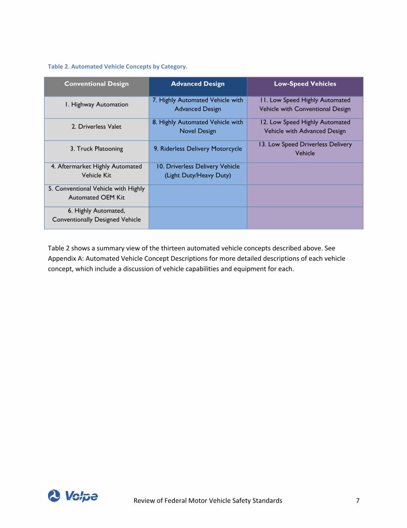
Table 2. Automated Vehicle Concepts by Category.
Conventional Design Advanced Design Low-Speed Vehicles
1. Highway Automation 7. Highly Automated Vehicle with
Advanced Design
11. Low Speed Highly Automated
Vehicle with Conventional Design
2. Driverless Valet 8. Highly Automated Vehicle with
Novel Design
12. Low Speed Highly Automated
Vehicle with Advanced Design
3. Truck Platooning 9. Riderless Delivery Motorcycle 13. Low Speed Driverless Delivery
Vehicle
4. Aftermarket Highly Automated
Vehicle Kit
10. Driverless Delivery Vehicle
(Light Duty/Heavy Duty)
5. Conventional Vehicle with Highly
Automated OEM Kit
6. Highly Automated,
Conventionally Designed Vehicle
Table 2 shows a summary view of the thirteen automated vehicle concepts described above. See
Appendix A: Automated Vehicle Concept Descriptions for more detailed descriptions of each vehicle
concept, which include a discussion of vehicle capabilities and equipment for each.
Review of Federal Motor Vehicle Safety Standards 8
Summary of Findings 3.
3.1 Driver Reference Scan
Two general findings emerged from the scan of FMVSS focused on references to a driver:
First, most references to a driver do not preclude certifying a vehicle with automated capabilities, as
long as that vehicle design allows a human driver to operate the vehicle with a wheel and pedals. Even
with advanced automated vehicle concepts, if the automated vehicle reserves a seating position for a
human driver, and the human driver is actually able to drive the vehicle, few, if any, of the documented
driver references present a conflict in and of themselves.
Second, the FMVSS provide a definition for a driver (“Driver means the occupant of the motor vehicle
seated immediately behind the steering control system” – §571.3) and uses the term “operator” or the
passive voice in some sections. The terms “driver” and “operator” are used interchangeably. As a
general observation, language throughout the FMVSS is clear in a world where all vehicles require a
human driver for manual control, but the meaning of the term “driver” could become less certain or
different when considered in the context of vehicles with increasingly automated capabilities.
Subsequent to the Volpe Center’s review of the FMVSS, NHTSA issued an interpretation letter to Google,
Inc. regarding the definition of driver in the context of a self-driving vehicle. In requesting an
interpretation from NHTSA, Google argues that its self-driving system (SDS) (an artificial intelligence
computer designed into the motor vehicle to control all aspects of driving by perceiving its environment
and responding to it) could be interpreted as the driver and operator of the vehicle. In response, NHTSA
interprets the concept of a driver, in the context of Google’s described motor vehicle design, as referring
to the SDS. However, the agency also cautions that this interpretation does not “end the inquiry or
determine the result,” suggesting that questions remain to be answered about whether and how Google
could certify that the SDS meets performance standards elsewhere in the FMVSS that were developed
and designed to apply to a vehicle with a human driver.3
It is important to note that the Volpe Center completed this review prior to the release of the NHTSA
interpretation letter to Google and, therefore, its findings do not reflect this subsequent development.
3 For the full text of NHTSA’s interpretation letter, see: http://isearch.nhtsa.gov/files/Google%20--
%20compiled%20response%20to%2012%20Nov%20%2015%20interp%20request%20--%204%20Feb%2016%20final.htm

Review of Federal Motor Vehicle Safety Standards 9
3.2 Automated Vehicle Concepts Scan
3.2.1 Conventional Vehicle Concepts
For selected concepts, the review of the FMVSS revealed few requirements that may interfere with a
manufacturer’s ability to certify an automated vehicle, particularly for concepts one through six and
eleven. The Volpe Center found that ‘Theft Protection and Rollaway Prevention, and ‘Light Vehicle Brake
Systems’ pose the most significant challenges for conventionally designed highly automated vehicle
concepts.
3.2.1.1 Theft Protection and Rollaway Prevention (571.114)
Section S5.2.2 specifies the following: “Except as specified in S5.2.4, the vehicle must be designed such
that the transmission or gear selection control cannot move from the “park” position, unless the key is
in the starting system.” This requirement may present a challenge to the certification of a vehicle
equipped with a driverless valet system, which would likely be controlled via a smartphone application
or other remote device (BMW’s Remote Park Assist system, for example, has been demonstrated using a
smartwatch). Section S4 of the standard defines a key as”…a physical device or an electronic code which,
when inserted into the starting system (by physical or electronic means), enables the vehicle operator to
activate the engine or motor.” The reference to an electronic code has historically been applied to the
use of keyless ignition systems, which rely on a wireless transponder that drivers must possess, but do
not need to be physically inserted into the car. Electronic keys establish a direct wireless connection
with the car to activate the ignition. Though it is possible that NHTSA could interpret a signal from an
authorized smartphone as an electronic code as defined in the standard, this form of an electronic key
transmitted via cellular signal and not directly to the car reflects a fundamentally different form of
electronic key. If NHTSA does not believe it can interpret a signal transmitted from a smartphone
application to a vehicle as an electronic key, then vehicles equipped with a driverless valet system (and
other automated vehicles that are capable of driverless operation and being summoned remotely) could
face a challenge in certifying to this standard.
Section S5.3 specifies “Each motor vehicle…with an automatic transmission that includes a ‘park’
position shall be equipped with a system that requires the service brake to be depressed before the
transmission can be shifted out of ‘park.’ This system shall function in any starting system key position in
which the transmission can be shifted out of ‘park.’” Though an automated vehicle could be
programmed to activate the service brakes prior to shifting out of park, the Volpe Center team viewed
the word “depressed” as applying the brake pedal. Interpreted in this way, a driverless valet system, for
Review of Federal Motor Vehicle Safety Standards 10
example, would not be able to certify compliance with this standard if it was designed to shift the
vehicle’s transmission out of park without depressing the brake pedal.4
Sections S5.2.3 and S5.2.4 specify key removal and gear selection override requirements, respectively.
That is, S5.2.3 specifies conditions under which a vehicle’s key can be removed when its transmission is
not in park, while S5.2.4 specifies conditions under which a vehicle’s transmission can be shifted out of
park when its key is not in the ignition. With the exception of cases of electrical failure, both subsections
require that forward mobility and/or steering are disabled. Based on the interpretations as described
above, certain highly automated vehicle concepts may be precluded from shifting out of park and into a
driving mode.
3.2.1.2 Light Vehicle Brake Systems (571.135)
Section S5.3.1 specifies “The service brakes shall be activated by means of a foot control.” An
interpretation of this requirement is that the only way the service brakes can be activated is by a foot
control. Although additional means of applying the service brakes are permissible, those means are not
a substitute for meeting this provision. Under this interpretation, most automated vehicle systems,
including near-term systems like highway autopilot, may have trouble certifying to this standard.5
3.2.2 Advanced Concepts
The more advanced automation concepts that the Volpe team considered are likely to face greater
challenges in certifying to the current version of FMVSS, particularly as provisions for driver control are
4 Subsequent to the Volpe Center’s review of the FMVSS, NHTSA issued an interpretation letter to BMW of North
America regarding its Park Assistant Plus system. The system in question allows a driver to place their vehicle in park, turn off the propulsion system, exit the vehicle, and then use the vehicle’s key fob to initiate a parking maneuver from outside the vehicle. As part of the parking maneuver, the vehicle propulsion system is activated and its brakes are applied using the electronic stability control (ESC) pump, allowing the transmission to be shifted out of park. In its interpretation, NHTSA indicates that the phrase “service brake to be depressed” is ambiguous and leaves room for interpretation. Because the standard does not specify that the service brake must be pressed or applied by a particular object or function, NHTSA interprets the application of the service brakes using the ESC pump, prior to shifting the transmission out of park, as achieving the goal of Section 5.3. For the full text of NHTSA’s interpretation letter, see: http://isearch.nhtsa.gov/files/15-005347%20BMW%20Brake%20Transmission%20Shift%20Interlock%20v5.htm 5 Subsequent to the Volpe Center’s review of the FMVSS, NHTSA issued an interpretation letter to Google, Inc. in
response to several questions about a self-driving vehicle it is in the process of developing and testing. In describing its self-driving vehicle Google indicated their intent to produce a vehicle that does not include conventional manual controls, including a steering wheel, accelerator, or brake pedal. One of Google’s questions pertained to the applicability of FMVSS No. 135 and the requirement for a foot-actuated service brake control stated in S5.3.1. NHTSA’s response letter indicates that, while the SDS that controls Google’s vehicle could be programmed to satisfy the performance requirements of FMVSS No. 135, this capability does not overcome the plain language stated in S5.3.1 requiring a foot-actuated service brake control. For the full text of NHTSA’s interpretation letter, see: http://isearch.nhtsa.gov/files/Google%20--%20compiled%20response%20to%2012%20Nov%20%2015%20interp%20request%20--%204%20Feb%2016%20final.htm
Review of Federal Motor Vehicle Safety Standards 11
removed. If manufacturers want to sell vehicles only intended for automated operation, with no way for
human occupants to drive the vehicle, they are likely to have difficulty certifying to requirements for a
foot-actuated service brake control (517.135), a designated seating position for the driver (571.207), a
steering wheel (a requirement for completing tests specified in 571.126), and certain controls and
displays. As manufacturers consider rearranging seating positions and changing other aspects of vehicle
design to take advantage of highly automated capabilities, requirements for rear visibility (571.111),
occupant protection (571.208), and other equipment may pose barriers to certification.
3.2.3 Low-Speed Vehicles
Low speed vehicles (designed to not exceed 25 miles per hour) face significantly fewer requirements
than conventional light and heavy duty vehicles, and therefore, may present an easier path through
which manufacturers might try to certify an automated vehicle, depending on the design choices that
the manufacturer wishes to make. Per FMVSS No. 500, low-speed vehicles must be equipped with
headlights, taillights, stop lamps, rear-view mirrors, and seatbelts, and must conform to the rear
visibility requirements established in 571.111. Low-speed vehicles must also comply with S5.3 of
571.114, which requires that any motor vehicle equipped with an automatic transmission that includes a
“park” position, must also be equipped with a system that “…requires the service brake to be depressed
before the transmission can be shifted out of ‘park’.” In order to comply with this requirement, low-
speed vehicles also need to be equipped with a gear shift mechanism. A low-speed vehicle may also
need to be equipped with a pedal to activate the service brakes in order to comply with this standard,
but the explicit requirement for a brake pedal contained in 571.135 does not apply to low-speed
vehicles.
3.2.4 Aftermarket Systems
The Volpe Center considered as part of its FMVSS review a concept in which a third-party automation
system is added to a production vehicle after it has been sold to an individual. Third-party automation
systems would be motor vehicle equipment, and as such, able to be regulated by NHTSA. Even without
a specific FMVSS applicable to a third-party automation system, there are a number of mechanisms by
which NHTSA could regulate its use. 49 CFR 567 contains a provision for vehicles that are altered after
they are certified by their original manufacturer but before they are sold. If such alterations are
performed “…in such a manner as may affect the conformity of the vehicle with one or more Federal
Motor Vehicle Safety Standard(s)…” then the person performing the alterations is responsible for
determining whether the vehicle continues to conform with FMVSS. Additionally, if installation causes
any part of the vehicle to be removed from compliance with the FMVSS, NHTSA could pursue
enforcement action (see 49 U.S.C. 30122), and NHTSA has additional enforcement authority to pursue
safety defects associated with motor vehicle equipment.
Review of Federal Motor Vehicle Safety Standards 12
3.2.5 FMVSS Definitions
The review revealed some concerns related to how such vehicles might be classified within the existing
definitions contained within FMVSS. For example, within §571.3 “Definitions”, a motorcycle is defined
as “…a motor vehicle with motive power having a seat or saddle for the use of the rider and designed to
travel on not more than three wheels in contact with the ground.” Given the plain language of this
definition, if the delivery motorcycle concept proposed in the review were not equipped with “a seat or
saddle for the use of the rider” (needing none), it may not be considered a motorcycle and, therefore,
might be subject to standards that do not typically apply to conventional motorcycles. Instead, it could
potentially be classified as a passenger car, defined as “…a motor vehicle with motive power, except a
low-speed vehicle, multipurpose passenger vehicle, motorcycle, or trailer, designed for carrying 10
persons or less.” After all, it is a motor vehicle with motive power designed to carry 10 people or less
(more specifically, zero people).
This is not to suggest that such a vehicle could be certified to the requirements of FMVSS as a passenger
car. Not only would a motorcycle (in form, if not in legal classification) have trouble meeting many of the
requirements to which passenger vehicles are subject (e.g., occupant protection), but many of the
requirements and test procedures would make little sense when applied to a vehicle resembling a
motorcycle (any reference to a door, for example, would become difficult to interpret). This observation
is important to consider in light of the ways in which perverse incentives have induced unusual (but
legitimate in the context of relevant definitions) vehicle classifications by manufacturers. It is possible
that definitions, including that of “motorcycle” among others, may warrant revisiting or supplementing
in order to avoid stifling innovation while still ensuring safety to the greatest extent possible.
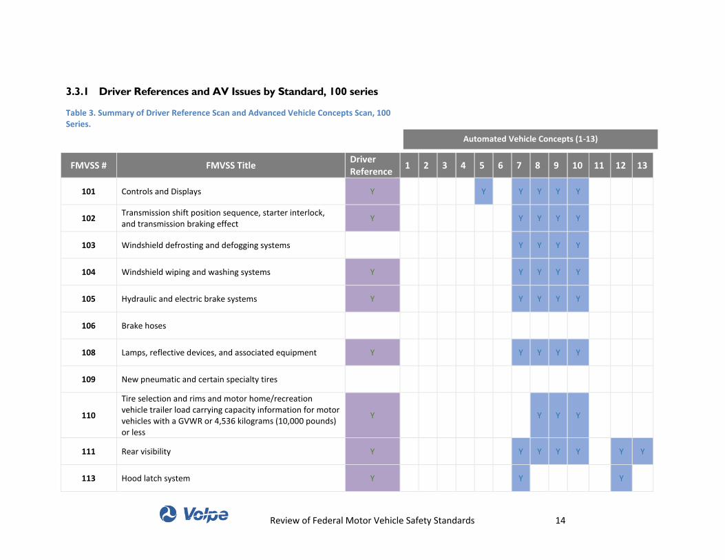
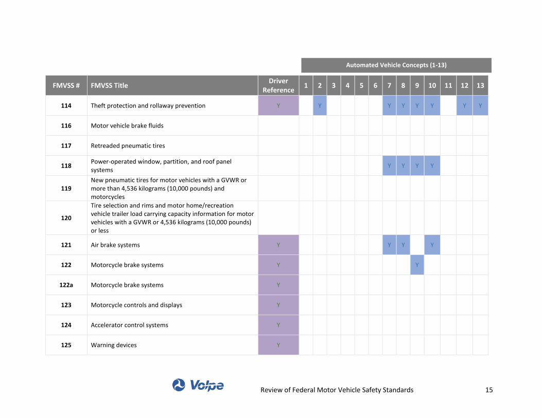
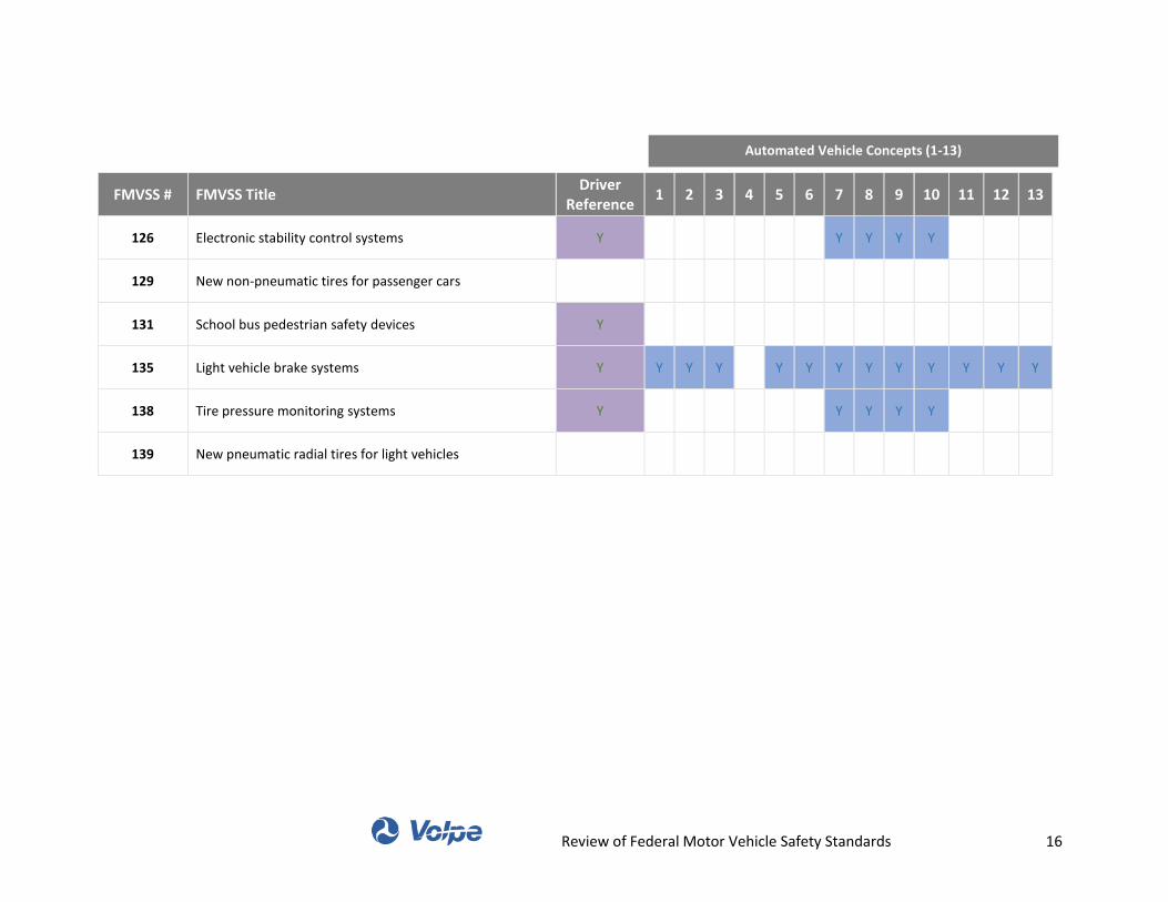
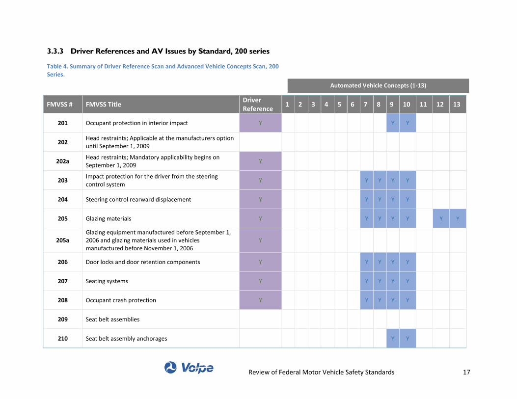
3.3 Table Summaries of Standards by Series
This section lists all 73 standards specified in the FMVSS and provides table summaries of the overall
results from both scans. The tables show which standards were identified as having driver references as
well as which standards were identified as part of the advanced vehicle concepts scan. In summary, the
two scans resulted in the following:
Driver Reference Scan: 33 of 73 FMVSS’s may present certification challenges for certain types of automated vehicles because they contain references to a driver.
Automated Vehicle Concepts Scan: 32 of 73 FMVSS’s may present certification challenges for certain types of automated vehicles because they contain performance specifications, test procedures, or equipment requirements that present potential barriers to the certification of one or more AV concepts.
The two reviews identified two distinct groups of standards.
The tables below provide a high-level summary of the standards identified through each scan. In the
context of the automated vehicle concepts, standards marked with a “Y” suggest the presence of
language, test procedures, or other content that might create certification challenges for the relevant

Review of Federal Motor Vehicle Safety Standards 13
concept. The table lists the following automated vehicle concepts by number (additional detail for each
concept is available in Appendix A):
1. Highway Automation
2. Driverless Valet
3. Truck Platooning
4. Aftermarket Highly Automated Vehicle Kit
5. Conventional Vehicle with Highly
Automated OEM Add-on Kit
6. Highly Automated, Conventionally
Designed Vehicle
7. Highly Automated Vehicle with Advanced
Design
8. Highly Automated Vehicle with Novel
Design
9. Riderless Delivery Motorcycle
10. Driverless Delivery Vehicle (Light Duty and
Heavy Duty)
11. Low-Speed Highly Automated Vehicle with
Conventional Design
12. Low-Speed Highly Automated Vehicle with
Advanced Design
13. Low-Speed Driverless Delivery Vehicle
Review of Federal Motor Vehicle Safety Standards 14
3.3.1 Driver References and AV Issues by Standard, 100 series
Table 3. Summary of Driver Reference Scan and Advanced Vehicle Concepts Scan, 100 Series.
FMVSS # FMVSS Title Driver Reference
1 2 3 4 5 6 7 8 9 10 11 12 13
101 Controls and Displays Y
Y
Y Y Y Y
102 Transmission shift position sequence, starter interlock, and transmission braking effect
Y
Y Y Y Y
103 Windshield defrosting and defogging systems
Y Y Y Y
104 Windshield wiping and washing systems Y
Y Y Y Y
105 Hydraulic and electric brake systems Y
Y Y Y Y
106 Brake hoses
108 Lamps, reflective devices, and associated equipment Y
Y Y Y Y
109 New pneumatic and certain specialty tires
110
Tire selection and rims and motor home/recreation vehicle trailer load carrying capacity information for motor vehicles with a GVWR or 4,536 kilograms (10,000 pounds) or less
Y
Y Y Y
111 Rear visibility Y
Y Y Y Y
Y Y
113 Hood latch system Y
Y
Y
Automated Vehicle Concepts (1-13)
Review of Federal Motor Vehicle Safety Standards 15
FMVSS # FMVSS Title Driver
Reference 1 2 3 4 5 6 7 8 9 10 11 12 13
114 Theft protection and rollaway prevention Y
Y
Y Y Y Y
Y Y
116 Motor vehicle brake fluids
117 Retreaded pneumatic tires
118 Power-operated window, partition, and roof panel systems
Y Y Y Y
119 New pneumatic tires for motor vehicles with a GVWR or more than 4,536 kilograms (10,000 pounds) and motorcycles
120
Tire selection and rims and motor home/recreation vehicle trailer load carrying capacity information for motor vehicles with a GVWR or 4,536 kilograms (10,000 pounds) or less
121 Air brake systems Y
Y Y
Y
122 Motorcycle brake systems Y
Y
122a Motorcycle brake systems Y
123 Motorcycle controls and displays Y
124 Accelerator control systems Y
125 Warning devices Y
Automated Vehicle Concepts (1-13)
Review of Federal Motor Vehicle Safety Standards 16
FMVSS # FMVSS Title Driver
Reference 1 2 3 4 5 6 7 8 9 10 11 12 13
126 Electronic stability control systems Y
Y Y Y Y
129 New non-pneumatic tires for passenger cars
131 School bus pedestrian safety devices Y
135 Light vehicle brake systems Y Y Y Y
Y Y Y Y Y Y Y Y Y
138 Tire pressure monitoring systems Y
Y Y Y Y
139 New pneumatic radial tires for light vehicles
Automated Vehicle Concepts (1-13)
Review of Federal Motor Vehicle Safety Standards 17
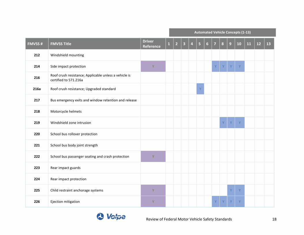
3.3.3 Driver References and AV Issues by Standard, 200 series
Table 4. Summary of Driver Reference Scan and Advanced Vehicle Concepts Scan, 200 Series.
FMVSS # FMVSS Title Driver Reference
1 2 3 4 5 6 7 8 9 10 11 12 13
201 Occupant protection in interior impact Y
Y Y
202 Head restraints; Applicable at the manufacturers option until September 1, 2009
202a Head restraints; Mandatory applicability begins on September 1, 2009
Y
203 Impact protection for the driver from the steering control system
Y
Y Y Y Y
204 Steering control rearward displacement Y
Y Y Y Y
205 Glazing materials Y
Y Y Y Y
Y Y
205a Glazing equipment manufactured before September 1, 2006 and glazing materials used in vehicles manufactured before November 1, 2006
Y
206 Door locks and door retention components Y
Y Y Y Y
207 Seating systems Y
Y Y Y Y
208 Occupant crash protection Y
Y Y Y Y
209 Seat belt assemblies
210 Seat belt assembly anchorages
Y Y
Automated Vehicle Concepts (1-13)
Review of Federal Motor Vehicle Safety Standards 18
FMVSS # FMVSS Title Driver Reference
1 2 3 4 5 6 7 8 9 10 11 12 13
212 Windshield mounting
214 Side impact protection Y
Y Y Y Y
216 Roof crush resistance; Applicable unless a vehicle is certified to 571.216a
216a Roof crush resistance; Upgraded standard
Y
217 Bus emergency exits and window retention and release
218 Motorcycle helmets
219 Windshield zone intrusion
Y Y Y
220 School bus rollover protection
221 School bus body joint strength
222 School bus passenger seating and crash protection Y
223 Rear impact guards
224 Rear impact protection
225 Child restraint anchorage systems Y
Y Y
226 Ejection mitigation Y
Y Y Y Y
Automated Vehicle Concepts (1-13)
Review of Federal Motor Vehicle Safety Standards 19
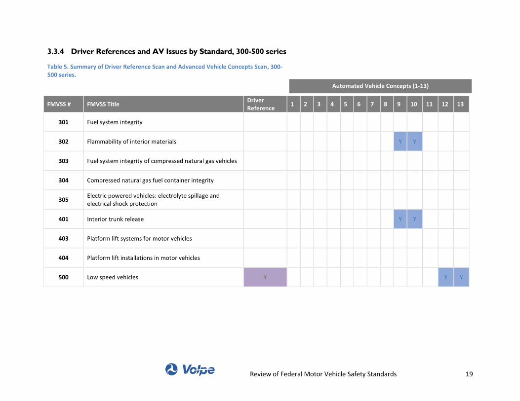
3.3.4 Driver References and AV Issues by Standard, 300-500 series
Table 5. Summary of Driver Reference Scan and Advanced Vehicle Concepts Scan, 300-500 series.
FMVSS # FMVSS Title Driver Reference
1 2 3 4 5 6 7 8 9 10 11 12 13
301 Fuel system integrity
302 Flammability of interior materials
Y Y
303 Fuel system integrity of compressed natural gas vehicles
304 Compressed natural gas fuel container integrity
305 Electric powered vehicles: electrolyte spillage and electrical shock protection
401 Interior trunk release
Y Y
403 Platform lift systems for motor vehicles
404 Platform lift installations in motor vehicles
500 Low speed vehicles Y
Y Y
Automated Vehicle Concepts (1-13)
Review of Federal Motor Vehicle Safety Standards 20
Summary and Areas for Further 4.
Discussion
The Federal Motor Vehicle Safety Standards (FMVSS) play a significant role in ensuring the safety of
vehicles and the people who use them. Manufacturers of new motor vehicles and items of motor vehicle
equipment must self-certify that their vehicle or equipment conforms and complies with the minimum
safety performance requirements outlined in the FMVSS.
With the introduction of highly automated vehicles, including self-driving systems, there is the question
as to whether the existing vehicle safety standards create unforeseen and unwarranted challenges for
these innovative technologies. The FMVSS were developed at a time where it was reasonable to assume
that all vehicles would be operated by a human driver and therefore also include a steering wheel,
accelerator pedal, and brake pedal, almost always located in the front left seating position. As a result,
many of the FMVSS include references to a human driver and/or assumes the presence of one.
This preliminary report identifies instances where the existing FMVSS may pose challenges to the
introduction of a range of automated vehicles. It identifies standards requiring further review – both to
ensure that existing regulations do not unduly stifle innovation and to help ensure that automated
vehicles are able to perform their functions safely. The review did not identify where there may need to
be new vehicle safety standards and regulations and was limited to only assessing the existing
standards. The review also did not assess whether the identified (or other) constraints may, in fact,
serve a safety need; this work does not assess the merits of the requirements for automated vehicles.
The Volpe team conducted two reviews of the FMVSS: a driver reference scan to identify which
standards include an explicit or implicit reference to a human driver and an automated vehicle concepts
scan to identify which standards could pose a challenge for a wide range of automated vehicle
capabilities and concepts. For the automated vehicle concepts scan, the team developed thirteen
automated vehicle concepts covering a wide range of plausible applications of automated vehicle
technology. This range included limited automation applications and highly automated, driverless
concepts with innovative vehicle designs.
The driver reference scan revealed reference to a human driver in 33 of the FMVSS. Yet, most references
to a driver do not – in and of themselves – preclude certifying a vehicle with automated capabilities as
long as that vehicle design enables a human to operate the vehicle with a wheel and pedals. In addition,
the definition of the term “driver” would require further interpretation in the context of a vehicle that is
occasionally or exclusively controlled by advanced software. Currently, the definition of a “driver”
means the occupant of the motor vehicle seated immediately behind the steering control system” –
§571.3), but how this definition is interpreted could become less clear as highly automated vehicles take
over more of the driving function.
The automated vehicle concepts scan showed just a few standards present challenges for certifying an
automated vehicle to FMVSS as long as the vehicle does not significantly differ from conventional
vehicle design. Two standards: theft protection and rollaway prevention (§571.114) and light vehicle
Review of Federal Motor Vehicle Safety Standards 21
brake systems (§571.135) were identified as having potential issues for automated vehicles with
conventional designs.
As automated vehicle concepts begin to push the boundaries of conventional design, the number of
FMVSS that could pose a challenge significantly increases. For example, automated vehicle concepts that
include alternative cabin layouts and omit human controls would face numerous constraints in the
current FMVSS. For driverless concepts, where human occupants have no way of driving the vehicle, the
standards for controls and displays (§571.101), rear visibility (§571.111) and occupant crash protection
(§571.208) could become problematic and require further review.
In summary, the review of current FMVSS revealed that a few standards present barriers to the
introduction of vehicles that have automated capabilities but retain the overall design, seating
arrangement, and human-machine interfaces of a conventional passenger car. However, as
manufacturers seek to translate the capabilities of increasing levels of automation into novel designs,
control interfaces, and other characteristics, the existing regulatory framework could constrain the
evolution of such vehicle designs, and new vehicle designs may create new safety issues that need
evaluation, and which this report does not address. The agency will have to consider what regulatory
changes may be needed to continue to ensure safety while not unduly stifling innovation. Continual
assessment of the FMVSS will likely be needed to balance the need for public safety with both the near
and long term development of these rapidly advancing technologies.
Review of Federal Motor Vehicle Safety Standards 22
Appendix A: Automated Vehicle
Concept Descriptions
This section provides detailed descriptions for each of the hypothetical vehicle concepts developed as part of the Automated Vehicle Concept Scan. In developing each vehicle concept, the team specified technical capabilities, vehicle equipment, and other characteristics that help to define the concept.
1. Highway Automation
Sold as an option on new equipment.
Offers a hands-free/foot-free highway vehicle control system.
System maintains lateral lane position and following distance to lead car based on input from
onboard sensors.
System usage is restricted to limited-access, divided highways.
System is not capable of global navigation, emergency evasive maneuvers (with the exception of
emergency braking), navigating intersections, or operating the vehicle’s transmission.
Vehicle retains all manual controls (i.e. brake and throttle pedals, steering wheel, transmission gear
selector).
2. Driverless valet
Sold as an option on new equipment.
Driver and other occupants exit vehicle while the vehicle is in park, with the engine running.
Driver tells the vehicle to go find a parking spot via smartphone.
Vehicle locks doors and uses an arrangement of sensors to locate a vacant parking space and navigate
to it.
Vehicle enters the space, stops moving, shifts to park, and disables the propulsion system.
When ready, the driver sends a pick-up signal to the vehicle via smart-phone.
Vehicle receives signal, enables the propulsion system, shifts into gear, returns to the drop-off
location, stops motions, and shifts to park, and unlocks doors when prompted.
Driver and occupants enter the vehicle.
Driver signals to the vehicle via smartphone or in-vehicle button, and regains full control.
3. Truck platooning
Sold as option on new equipment.
The optional equipment enables following vehicles to trail behind lead vehicle at close distance. The
lead vehicle is driven by a human. The trailing vehicles are controlled by a combination of human and
machine.
Lead vehicle broadcasts brake input and vehicle speed to trailing vehicles. Trailing vehicles use the
broadcast message as a system input to control following distance with throttle and brakes. By
following closely, the vehicle platoon has lower net drag and better real world fuel economy.
Trailing vehicles broadcast telltale indicators to lead vehicle.
Trailing vehicles broadcast video of road surroundings to lead vehicle.
A dashboard indicator light confirms engaged or disengaged platoon links.
Vehicles use cameras and dashboard mounted display instead of mirrors.
Following vehicles may also automate steering inputs.
Review of Federal Motor Vehicle Safety Standards 23
4. Aftermarket highly automated vehicle kit
Smart phone input and/or in vehicle button activate/deactivate highly automated capability.
Destination programmed via smartphone.
Roof based aftermarket module enables highly automated functionality.
Sensing via lidar and image detection.
On kit computer interprets inputs and directs vehicle via CAN-Bus.
Closed loop control of throttle, steering, brakes, and signals via CAN-Bus.
5. Conventional Vehicle with Highly Automated OEM Add-on Kit
Vehicle may be operated with key and driven traditionally, or vehicle may be programmed via
authorized smartphone with destination(s) and deployed with or without occupants.
If operated via smartphone, the operator interface is similar to that of the “driverless valet” concept,
but the operator may deploy the vehicle on roadways at high speeds.
6. Highly automated, conventionally designed vehicle
Driver may operate the vehicle with traditional controls, including steering wheel, pedals, signal
inputs, and shifter – or the vehicle may be enabled to start and move with zero driver inputs.
Sensors survey the external operating environment and provide inputs for computer control.
Vehicle has all equipment that is required today to pass FMVSS, arranged in a conventional manner.
7. Highly automated vehicle with advanced vehicle design
Operator provides destination inputs via smartphone.
Vehicle has no steering wheel, no brake pedals, and no shifter, so that human occupants cannot drive
the vehicle. There is a panic button that may be depressed in case of an emergency.
Vehicle has no side view mirrors and no back-up camera display.
Vehicle does have windshield, windshield wipers, windows, and defog / defrost, though vision angles
may not conform to FMVSS guidance.
Vehicle does have headlights, tail lights, and turn signals. These indicators would be able to be
interpreted by non-automated vehicles and human drivers.
Vehicle does have telltales visible to the front left occupant when the occupant is facing forward.
Seats are arranged in a conventional manner, but occupants can spin front seats to face rearward.
8. Highly automated vehicle with novel design
Operator provides destination inputs via smartphone.
Vehicle has no steering wheel, no brake pedals, and no shifter, so that human occupants cannot drive
the vehicle. There is a panic button that may be depressed in case of an emergency.
Vehicle has no park brake system.
Vehicle has no side view mirrors and no back-up camera display.
Vehicle has no sun visors.
Vehicle does not have windshield, windshield wipers, and defog / defrost.
Vehicle has small side windows that may be raised and lowered via control from an authorized smart
phone.
Vehicle has large video display devices mounted on the interior where the windshield / rear window
would be. These can display video of outside captured via cameras, or video of other media.
The vehicle does not have headlights, but the vehicle is illuminated while driving in the dark.
Review of Federal Motor Vehicle Safety Standards 24
Vehicle does not have telltales in the vehicle, but vehicle information is available via smartphone
interface.
Vehicle does not have tail lights or turn signals, but rather could wirelessly communicate braking and
turn signal indications to other vehicles.
Seats are arranged in a new manner; “driver’s seat” designation is no longer clear.
Vehicle has no hood. All service is done on modules that may be removed from a lifted car.
Vehicle is all electric and has no fluid fuel system.
Climate control systems are operated by authorized occupants via smartphone.
9. Riderless delivery motorcycle
Vehicle operates independently from shipping depot to drop-off location.
Vehicle has 2 or 3 wheels.
Vehicle is programmed with one or more delivery destinations.
After the vehicle is loaded, the vehicle is activated via electronic signal.
Vehicle enables the propulsion system, shifts gear, and begins driving.
Upon reaching a drop off location, the vehicle stops motion, shifts to park, and sends a signal to the
receiver of the delivery that the package is available for pick-up.
Upon receiving signal that the package has been removed from the vehicle, the vehicle enables the
propulsion system, shifts to drive, and proceeds.
The vehicle has no provision for driver seating or driver controls, including turn signals, brakes,
throttle, and steering input.
The vehicle automatically illuminates turn signals and brake signals as appropriate.
The vehicle does not have headlights, but the vehicle is illuminated while driving in the dark.
The vehicle does not have gauges for speed and RPM, nor does the vehicle have telltales.
The vehicle only has an on/off indicator light, and diagnostic information is available via controller’s
smartphone or via on-board diagnostic plug in port.
10. Driverless delivery vehicle (Light Duty and Heavy Duty)
Vehicle operates independently from shipping depot to drop-off location.
Vehicle has 4 wheels.
Vehicle is programmed with one or more delivery destinations.
After the vehicle is loaded, the vehicle is enabled via electronic signal.
Vehicle enables the propulsion system, shifts gear, and begins driving.
Upon reaching a drop off location, the vehicle stops motion, shifts to park, and sends a signal to the
receiver of the delivery that the package is available for pick-up.
Upon receiving signal that the package has been removed from the vehicle, the vehicle enables the
propulsion system, shifts to drive, and proceeds.
The vehicle has no provision for human driver seating or driver controls, including turn signals,
brakes, throttle, and steering input.
The vehicle has no provision for seating of any kind.
The vehicle has no windows of any kind.
The vehicle has no mirrors of any kind.
The vehicle has no windshield wipers or defog / defrost of any kind.
The vehicle has a basic door to access the loading bays of the vehicle.
The vehicle automatically illuminates turn signals and brake signals as appropriate.
The vehicle does not have headlights, but the vehicle is illuminated while driving in the dark.
The vehicle does not have gauges for speed and RPM, nor does the vehicle have telltales.
Review of Federal Motor Vehicle Safety Standards 25
The vehicle only has an on/off indicator light, and diagnostic information is available via controller’s
smartphone or via on-board diagnostic plug in port.
11. Low speed highly automated vehicle with conventional design
Vehicle operates at speeds of less than 25mph.
Human driver may operate the vehicle with traditional controls, including steering wheel, pedals,
signal inputs, and shifter – or the vehicle may be enabled to start and move with only AI driver inputs.
Sensors survey the external operating environment and provide inputs for computer control.
Vehicle has all equipment that is required today to pass FMVSS, arranged in a conventional manner.
12. Low speed highly automated vehicle with advanced design
Operator provides destination inputs via smartphone.
Vehicle has no steering wheel, no brake pedals, and no shifter, so that human occupants cannot drive
the vehicle. There is a panic button that may be depressed in case of an emergency.
Vehicle has no side view mirrors and no back-up camera display.
Vehicle does have windshield, windshield wipers, windows, and defog / defrost, though vision angles
may not conform to FMVSS guidance.
Vehicle does have tail lights, and turn signals.
The vehicle does not have headlights, but the vehicle is illuminated while driving in the dark.
Vehicle does have telltales visible to the front left occupant when the occupant is facing forward.
Seats are arranged in a conventional manner, but occupants can spin front seats to face rearward.
13. Low speed driverless delivery vehicle
Vehicle operates at speeds of less than 25mph.
Vehicle operates independently from shipping depot to drop-off location.
Vehicle has 4 wheels.
Vehicle is programmed with one or more delivery destinations.
After the vehicle is loaded, the vehicle is enabled via electronic signal.
Vehicle enables the propulsion system, shifts gear, and begins driving.
Upon reaching a drop off location, the vehicle stops motion, shifts to park, and sends a signal to the
receiver of the delivery that the package is available for pick-up.
Upon receiving signal that the package has been removed from the vehicle, the vehicle enables the
propulsion system, shifts to drive, and proceeds.
The vehicle has no provision for human driver seating or driver controls, including turn signals,
brakes, throttle, and steering input.
The vehicle has no provision for seating of any kind.
The vehicle has no windows of any kind.
The vehicle has no mirrors of any kind.
The vehicle has no windshield wipers or defog / defrost of any kind.
The vehicle has a basic door to access the loading bays of the vehicle.
The vehicle automatically illuminates turn signals and brake signals as appropriate.
The vehicle does not have headlights, but the vehicle is illuminated while driving in the dark.
The vehicle does not have gauges for speed and RPM, nor does the vehicle have telltales.
The vehicle only has an on/off indicator light, and diagnostic information is available via controller’s
smartphone or via on-board diagnostic plug in port.
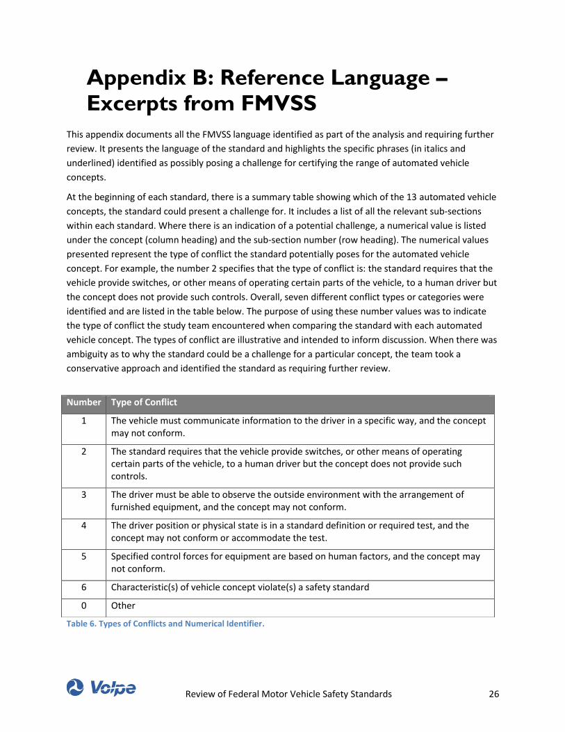
Review of Federal Motor Vehicle Safety Standards 26
Appendix B: Reference Language –
Excerpts from FMVSS
This appendix documents all the FMVSS language identified as part of the analysis and requiring further
review. It presents the language of the standard and highlights the specific phrases (in italics and
underlined) identified as possibly posing a challenge for certifying the range of automated vehicle
concepts.
At the beginning of each standard, there is a summary table showing which of the 13 automated vehicle
concepts, the standard could present a challenge for. It includes a list of all the relevant sub-sections
within each standard. Where there is an indication of a potential challenge, a numerical value is listed
under the concept (column heading) and the sub-section number (row heading). The numerical values
presented represent the type of conflict the standard potentially poses for the automated vehicle
concept. For example, the number 2 specifies that the type of conflict is: the standard requires that the
vehicle provide switches, or other means of operating certain parts of the vehicle, to a human driver but
the concept does not provide such controls. Overall, seven different conflict types or categories were
identified and are listed in the table below. The purpose of using these number values was to indicate
the type of conflict the study team encountered when comparing the standard with each automated
vehicle concept. The types of conflict are illustrative and intended to inform discussion. When there was
ambiguity as to why the standard could be a challenge for a particular concept, the team took a
conservative approach and identified the standard as requiring further review.
Table 6. Types of Conflicts and Numerical Identifier.
Number Type of Conflict
1 The vehicle must communicate information to the driver in a specific way, and the concept may not conform.
2 The standard requires that the vehicle provide switches, or other means of operating certain parts of the vehicle, to a human driver but the concept does not provide such controls.
3 The driver must be able to observe the outside environment with the arrangement of furnished equipment, and the concept may not conform.
4 The driver position or physical state is in a standard definition or required test, and the concept may not conform or accommodate the test.
5 Specified control forces for equipment are based on human factors, and the concept may not conform.
6 Characteristic(s) of vehicle concept violate(s) a safety standard
0 Other

Review of Federal Motor Vehicle Safety Standards 27
Table of Contents for FMVSS Reference Language
§571.3 Definitions. ............................................................................................................. 29
§571.7 Applicability. .......................................................................................................... 30
§571.10 Designation of seating positions. .......................................................................... 31
§571.101 Standard No. 101; Controls and displays. ............................................................ 32
§571.102 Standard No. 102; Transmission shift position sequence, starter interlock, and
transmission braking effect. ................................................................................................ 36
§571.103 Standard No. 103; Windshield defrosting and defogging systems. ....................... 38
§571.104 Standard No. 104; Windshield wiping and washing systems. ............................... 39
§571.105 Standard No. 105; Hydraulic and electric brake systems. ..................................... 40
§571.108 Standard No. 108; Lamps, reflective devices, and associated equipment. ............ 45
§571.110 Tire selection and rims and motor home/recreation vehicle trailer load carrying
capacity information for motor vehicles with a GVWR of 4,536 kilograms (10,000 pounds) or
less. 50
§571.111 Standard No. 111; Rear visibility. ........................................................................ 51
§571.113 Standard No. 113; Hood latch system. ................................................................. 59
§571.114 Standard No. 114; Theft protection and rollaway prevention. ............................. 60
§571.118 Standard No. 118; Power-operated window, partition, and roof panel systems. .. 63
§571.121 Standard No. 121; Air brake systems. .................................................................. 64
§571.122 Standard No. 122; Motorcycle brake systems. ..................................................... 67
§571.122a Standard No. 122; Motorcycle brake systems. ................................................... 76
§571.123 Standard No. 123; Motorcycle controls and displays............................................ 77
§571.124 Standard No. 124; Accelerator control systems. .................................................. 79
§571.125 Standard No. 125; Warning devices. .................................................................... 80
§571.126 Standard No. 126; Electronic stability control systems for light vehicles. .............. 81
§571.131 Standard No. 131; School bus pedestrian safety devices. ..................................... 87
Review of Federal Motor Vehicle Safety Standards 28
§571.135 Standard No. 135; Light vehicle brake systems. ................................................... 88
§571.138 Standard No. 138; Tire pressure monitoring systems. .......................................... 97
§571.201 Standard No. 201; Occupant protection in interior impact. ................................. 100
§571.202a Standard No. 202a; Head restraints; Mandatory applicability begins on
September 1, 2009. ............................................................................................................ 102
§571.203 Standard No. 203; Impact protection for the driver from the steering control
system. .............................................................................................................................. 103
§571.204 Standard No. 204; Steering control rearward displacement. ............................... 104
§571.205 Standard No. 205, Glazing materials. .................................................................. 105
§571.206 Standard No. 206; Door locks and door retention components. .......................... 106
§571.207 Standard No. 207; Seating systems. .................................................................... 108
§571.208 Standard No. 208; Occupant crash protection. ................................................... 109
§571.210 Standard No. 210; Seat belt assembly anchorages. ............................................. 120
§571.214 Standard No. 214; Side impact protection. ......................................................... 121
§571.216 Standard No. 216; Roof crush resistance; Applicable unless a vehicle is certified to
§571.216a. ......................................................................................................................... 127
§571.216a Standard No. 216a; Roof crush resistance; Upgraded standard. ........................ 128
§571.219 Standard No. 219; Windshield zone intrusion. .................................................... 129
§571.222 Standard No. 222; School bus passenger seating and crash protection. ............... 130
§571.225 Standard No. 225; Child restraint anchorage systems. ........................................ 131
§571.226 Standard No. 226; Ejection Mitigation. ............................................................... 132
§571.302 Standard No. 302; Flammability of interior materials. ........................................ 133
§571.401 Standard No. 401; Interior trunk release. ........................................................... 134
§571.500 Standard No. 500; Low-speed vehicles. .............................................................. 135
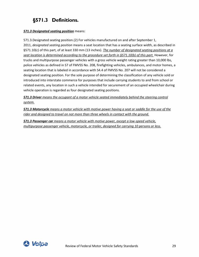
Review of Federal Motor Vehicle Safety Standards 29
§571.3 Definitions.
571.3 Designated seating position means:
571.3.Designated seating position.(2) For vehicles manufactured on and after September 1,
2011, designated seating position means a seat location that has a seating surface width, as described in
§571.10(c) of this part, of at least 330 mm (13 inches). The number of designated seating positions at a
seat location is determined according to the procedure set forth in §571.10(b) of this part. However, for
trucks and multipurpose passenger vehicles with a gross vehicle weight rating greater than 10,000 lbs,
police vehicles as defined in S7 of FMVSS No. 208, firefighting vehicles, ambulances, and motor homes, a
seating location that is labeled in accordance with S4.4 of FMVSS No. 207 will not be considered a
designated seating position. For the sole purpose of determining the classification of any vehicle sold or
introduced into interstate commerce for purposes that include carrying students to and from school or
related events, any location in such a vehicle intended for securement of an occupied wheelchair during
vehicle operation is regarded as four designated seating positions.
571.3 Driver means the occupant of a motor vehicle seated immediately behind the steering control
system.
571.3 Motorcycle means a motor vehicle with motive power having a seat or saddle for the use of the
rider and designed to travel on not more than three wheels in contact with the ground.
571.3 Passenger car means a motor vehicle with motive power, except a low-speed vehicle,
multipurpose passenger vehicle, motorcycle, or trailer, designed for carrying 10 persons or less.
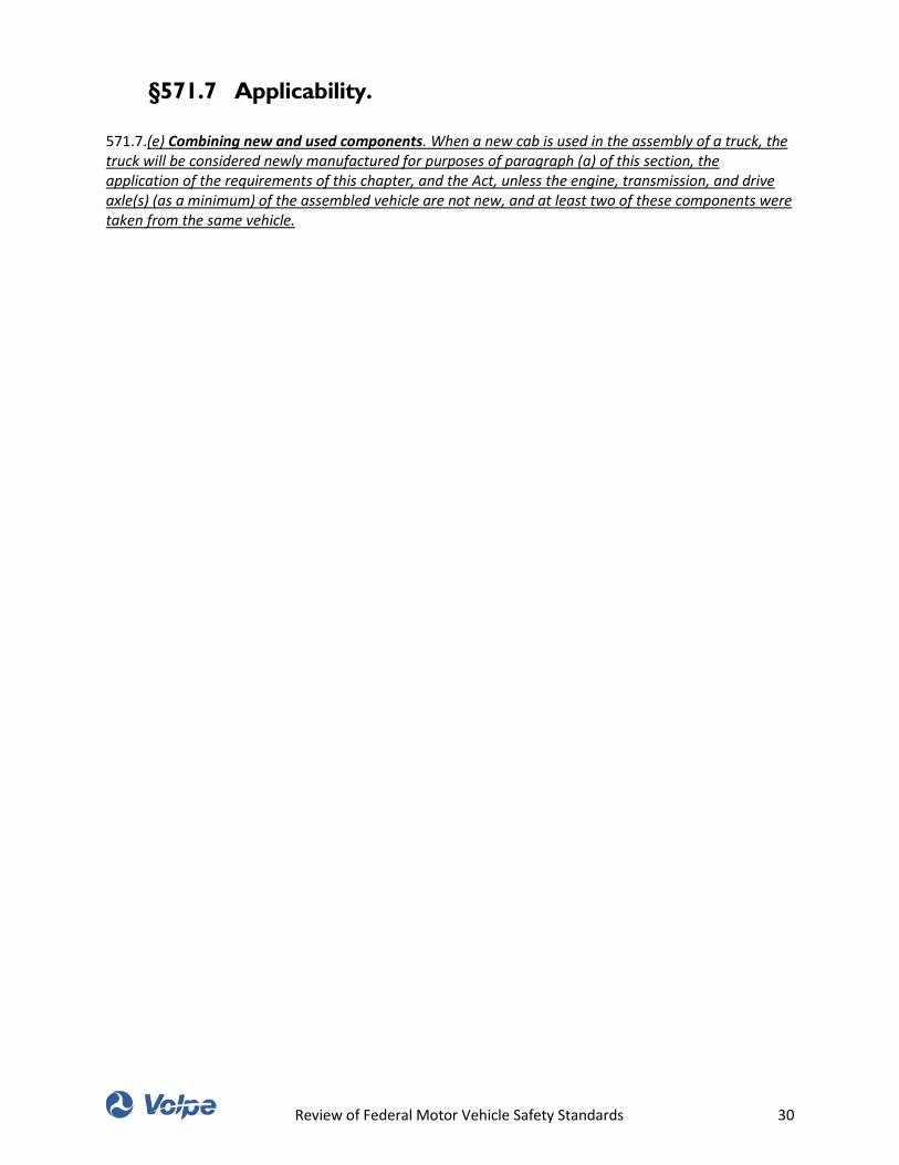
Review of Federal Motor Vehicle Safety Standards 30
§571.7 Applicability.
571.7.(e) Combining new and used components. When a new cab is used in the assembly of a truck, the truck will be considered newly manufactured for purposes of paragraph (a) of this section, the application of the requirements of this chapter, and the Act, unless the engine, transmission, and drive axle(s) (as a minimum) of the assembled vehicle are not new, and at least two of these components were taken from the same vehicle.
Review of Federal Motor Vehicle Safety Standards 31
§571.10 Designation of seating positions.
571.10 (a) Application. This section applies to passenger cars, trucks, multipurpose passenger vehicles, and buses manufactured on or after September 1, 2010. However, paragraph (b) of this section does not apply to trucks and multipurpose passenger vehicles with a gross vehicle weight rating greater than 10,000 lbs, school buses, police vehicles as defined in S7 of Standard No. 208 (49 CFR 571.208), firefighting vehicles, ambulances, or motor homes. To determine the number of passenger seating positions in school buses, see S4.1 of Standard No. 222 (49 CFR 571.222).
571.10 (b) Number of designated seating positions. The formula for calculating the number of designated seating positions (N) for any seat location with a seating surface width greater than 330 mm (13 inches) is as follows:
571.10.b.(1) For seat locations with a seating surface width, as described in paragraph (c), of less than 1400 mm (55.2 inches): N = The greater of 1 or [seating surface width (in mm)/350] rounded down to the nearest whole number;
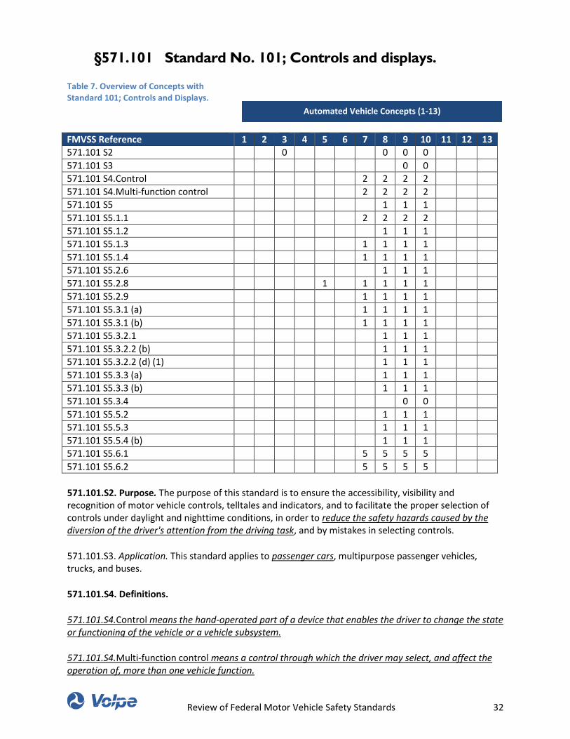
Review of Federal Motor Vehicle Safety Standards 32
§571.101 Standard No. 101; Controls and displays.
Table 7. Overview of Concepts with Standard 101; Controls and Displays.
FMVSS Reference 1 2 3 4 5 6 7 8 9 10 11 12 13
571.101 S2 0 0 0 0
571.101 S3 0 0
571.101 S4.Control 2 2 2 2
571.101 S4.Multi-function control 2 2 2 2
571.101 S5 1 1 1
571.101 S5.1.1 2 2 2 2
571.101 S5.1.2 1 1 1
571.101 S5.1.3 1 1 1 1
571.101 S5.1.4 1 1 1 1
571.101 S5.2.6 1 1 1
571.101 S5.2.8 1 1 1 1 1
571.101 S5.2.9 1 1 1 1
571.101 S5.3.1 (a) 1 1 1 1
571.101 S5.3.1 (b) 1 1 1 1
571.101 S5.3.2.1 1 1 1
571.101 S5.3.2.2 (b) 1 1 1
571.101 S5.3.2.2 (d) (1) 1 1 1
571.101 S5.3.3 (a) 1 1 1
571.101 S5.3.3 (b) 1 1 1
571.101 S5.3.4 0 0
571.101 S5.5.2 1 1 1
571.101 S5.5.3 1 1 1
571.101 S5.5.4 (b) 1 1 1
571.101 S5.6.1 5 5 5 5
571.101 S5.6.2 5 5 5 5
571.101.S2. Purpose. The purpose of this standard is to ensure the accessibility, visibility and recognition of motor vehicle controls, telltales and indicators, and to facilitate the proper selection of controls under daylight and nighttime conditions, in order to reduce the safety hazards caused by the diversion of the driver's attention from the driving task, and by mistakes in selecting controls.
571.101.S3. Application. This standard applies to passenger cars, multipurpose passenger vehicles, trucks, and buses.
571.101.S4. Definitions.
571.101.S4.Control means the hand-operated part of a device that enables the driver to change the state or functioning of the vehicle or a vehicle subsystem.
571.101.S4.Multi-function control means a control through which the driver may select, and affect the operation of, more than one vehicle function.
Automated Vehicle Concepts (1-13)
Review of Federal Motor Vehicle Safety Standards 33
571.101.S5. Requirements
571.101.S5. Requirements. Each passenger car, multipurpose passenger vehicle, truck and bus that is
fitted with a control, a telltale or an indicator listed in Table 1 or Table 2 must meet the requirements of
this standard for the location, identification, color, and illumination of that control, telltale or indicator.
However, the requirements for telltales and indicators do not apply to vehicles with GVWRs of 4,536 kg
or greater if these specified vehicles are manufactured before September 1, 2013.
571.101.S5.1 Location
571.101 S5.1.1 The controls listed in Table 1 and in Table 2 must be located so they are operable by the
driver under the conditions of S5.6.2.
571.101 S5.1.2 The telltales and indicators listed in Table 1 and Table 2 and their identification must be
located so that, when activated, they are visible to a driver under the conditions of S5.6.1 and S5.6.2.
571.101 S5.1.3 Except as provided in S5.1.4, the identification for controls, telltales and indicators must
be placed on or adjacent to the telltale, indicator or control that it identifies.
571.101 S5.1.4 The requirement of S5.1.3 does not apply to a multi-function control, provided the
multi-function control is associated with a multi-task display that:
571.101 S5.1.4 (a) Is visible to the driver under the conditions of S5.6.1 and S5.6.2,
571.101 S5.2 Identification
571.101 S5.2.6 Except as provided in S5.2.7, all identifications of telltales, indicators and controls listed
in Table 1 or Table 2 must appear to the driver to be perceptually upright. A rotating control that has an
“off” position shall appear to the driver perceptually upright when the rotating control is in the “off”
position.
571.101 S5.2.8 Each control for an automatic vehicle speed system (cruise control) and each control for heating and air conditioning systems must have identification provided for each function of each such system. 571.101 S5.2.9 Each control that regulates a system function over a continuous range must have identification provided for the limits of the adjustment range of that function. 571.101 S5.3 Illumination 571.101 S5.3.1 Timing of Illumination 571.101 S5.3.1 (a) Except as provided in S5.3.1(c), the identifications of controls for which the word “Yes” is specified in column 5 of Table 1 must be capable of being illuminated whenever the headlamps are activated.
Review of Federal Motor Vehicle Safety Standards 34
571.101 S5.3.1 (b) Except as provided in S5.3.1(c), the indicators and their identifications for which the word “Yes” is specified in column 5 of Table 1 must be illuminated whenever the vehicle's propulsion system and headlamps are activated. 571.101 S5.3.2 Brightness of illumination of controls and indicators 571.101 S5.3.2.1 Means must be provided for illuminating the indicators, identifications of indicators and identifications of controls listed in Table 1 to make them visible to the driver under daylight and nighttime driving conditions. 571.101 S5.3.2.2 The means of providing the visibility required by S5.3.2.1: 571.101 S5.3.2.2 (b) At a level of brightness other than the highest level, the identification of controls and indicators must be barely discernible to the driver who has adapted to dark ambient roadway condition; 571.101 S5.3.2.2 (d) May have levels of brightness, other than the two required visible levels of brightness, at which those items and identification are not visible. 571.101 S5.3.2.2 (d) (1) If the level of brightness is adjusted by automatic means to a point where those items or their identification are not visible to the driver, means shall be provided to enable the driver to restore visibility. 571.101 S5.3.3 Brightness of telltale illumination 571.101 S5.3.3 (a) Means must be provided for illuminating telltales and their identification sufficiently to make them visible to the driver under daylight and nighttime driving conditions. 571.101 S5.3.3 (b) The means for providing the required visibility may be adjustable manually or automatically, except that the telltales and identification for brakes, highbeams, turn signals, and safety belts may not be adjustable under any driving condition to a level that is invisible. 571.101 S5.3.4 Brightness of interior lamps. (a) Any source of illumination within the passenger compartment which is forward of a transverse vertical plane 110 mm rearward of the manikin “H” point with the driver's seat in its rearmost driving position, which is not used for the controls and displays regulated by this standard, which is not a telltale, and which is capable of being illuminated while the vehicle is in motion, shall have either: (1) Light intensity which is manually or automatically adjustable to provide at least two levels of brightness; (2) A single intensity that is barely discernible to a driver who has adapted to dark ambient roadway conditions; or (3) A means of being turned off. 571.101 S5.4 Color 571.101 S5.4.2 Any indicator or telltale not listed in Table 1 and any identification of that indicator or telltale must not be a color that masks the driver's ability to recognize any telltale, control, or indicator listed in Table 1. 571.101 S5.5 Common space for displaying multiple messages 571.101 S5.5.2 The telltales for any brake system malfunction required by Table 1 to be red, air bag malfunction, low tire pressure, electronic stability control malfunction (as of September 1, 2011), passenger air bag off, high beam, turn signal, and seat belt must not be shown in the same common space. 571.101 S5.5.3 The telltales and indicators that are listed in Table 1 and are shown in the common space must illuminate at the initiation of any underlying condition. 571.101 S5.5.4 Except as provided in S5.5.5, when the underlying conditions exist for actuation of two or
Review of Federal Motor Vehicle Safety Standards 35
more telltales, the messages must be either: (a) Repeated automatically in sequence, or (b) Indicated by visible means and capable of being selected for viewing by the driver under the conditions of S5.6.2. 571.101 S5.5.6 (a) Except as provided in S5.5.6(b), messages displayed in a common space may be cancelable automatically or by the driver. 571.101 S5.6 Conditions 571.101 S5.6.1 The driver has adapted to the ambient light roadway conditions. 571.101 S5.6.2 The driver is restrained by the seat belts installed in accordance with 49 CFR 571.208 and adjusted in accordance with the vehicle manufacturer’s instructions.
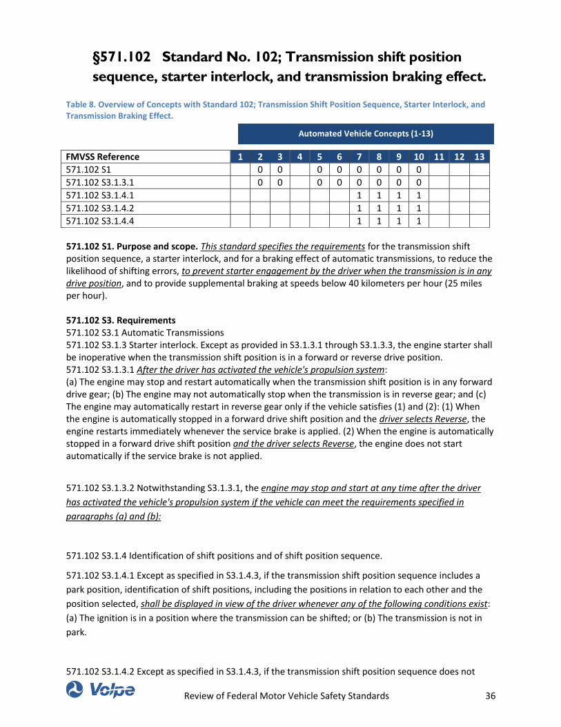
Review of Federal Motor Vehicle Safety Standards 36
§571.102 Standard No. 102; Transmission shift position
sequence, starter interlock, and transmission braking effect.
Table 8. Overview of Concepts with Standard 102; Transmission Shift Position Sequence, Starter Interlock, and Transmission Braking Effect.
FMVSS Reference 1 2 3 4 5 6 7 8 9 10 11 12 13
571.102 S1 0 0 0 0 0 0 0 0
571.102 S3.1.3.1 0 0 0 0 0 0 0 0
571.102 S3.1.4.1 1 1 1 1
571.102 S3.1.4.2 1 1 1 1
571.102 S3.1.4.4 1 1 1 1
571.102 S1. Purpose and scope. This standard specifies the requirements for the transmission shift position sequence, a starter interlock, and for a braking effect of automatic transmissions, to reduce the likelihood of shifting errors, to prevent starter engagement by the driver when the transmission is in any drive position, and to provide supplemental braking at speeds below 40 kilometers per hour (25 miles per hour). 571.102 S3. Requirements 571.102 S3.1 Automatic Transmissions 571.102 S3.1.3 Starter interlock. Except as provided in S3.1.3.1 through S3.1.3.3, the engine starter shall be inoperative when the transmission shift position is in a forward or reverse drive position. 571.102 S3.1.3.1 After the driver has activated the vehicle's propulsion system: (a) The engine may stop and restart automatically when the transmission shift position is in any forward drive gear; (b) The engine may not automatically stop when the transmission is in reverse gear; and (c) The engine may automatically restart in reverse gear only if the vehicle satisfies (1) and (2): (1) When the engine is automatically stopped in a forward drive shift position and the driver selects Reverse, the engine restarts immediately whenever the service brake is applied. (2) When the engine is automatically stopped in a forward drive shift position and the driver selects Reverse, the engine does not start automatically if the service brake is not applied.
571.102 S3.1.3.2 Notwithstanding S3.1.3.1, the engine may stop and start at any time after the driver
has activated the vehicle's propulsion system if the vehicle can meet the requirements specified in
paragraphs (a) and (b):
571.102 S3.1.4 Identification of shift positions and of shift position sequence.
571.102 S3.1.4.1 Except as specified in S3.1.4.3, if the transmission shift position sequence includes a
park position, identification of shift positions, including the positions in relation to each other and the
position selected, shall be displayed in view of the driver whenever any of the following conditions exist:
(a) The ignition is in a position where the transmission can be shifted; or (b) The transmission is not in
park.
571.102 S3.1.4.2 Except as specified in S3.1.4.3, if the transmission shift position sequence does not
Automated Vehicle Concepts (1-13)
Review of Federal Motor Vehicle Safety Standards 37
include a park position, identification of shift positions, including the positions in relation to each other
and the position selected, shall be displayed in view of the driver whenever the ignition is in a position in
which the engine is capable of operation.
571.102 S3.1.4.4 All of the information required to be displayed by S3.1.4.1 or S3.1.4.2 shall be displayed
in view of the driver in a single location. At the option of the manufacturer, redundant displays providing
some or all of the information may be provided.
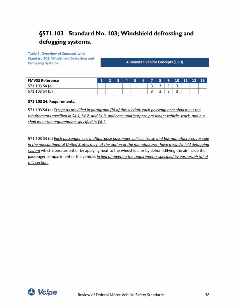
Review of Federal Motor Vehicle Safety Standards 38
§571.103 Standard No. 103; Windshield defrosting and
defogging systems.
Table 9. Overview of Concepts with Standard 103; Windshield Defrosting and Defogging Systems.
FMVSS Reference 1 2 3 4 5 6 7 8 9 10 11 12 13
571.103 S4 (a) 3 3 3 3
571.103 S4 (b) 3 3 3 3
571.103 S4. Requirements.
571.103 S4 (a) Except as provided in paragraph (b) of this section, each passenger car shall meet the
requirements specified in S4.1, S4.2, and S4.3, and each multipurpose passenger vehicle, truck, and bus
shall meet the requirements specified in §4.1.
571.103 S4 (b) Each passenger car, multipurpose passenger vehicle, truck, and bus manufactured for sale
in the noncontinental United States may, at the option of the manufacturer, have a windshield defogging
system which operates either by applying heat to the windshield or by dehumidifying the air inside the
passenger compartment of the vehicle, in lieu of meeting the requirements specified by paragraph (a) of
this section.
Automated Vehicle Concepts (1-13)
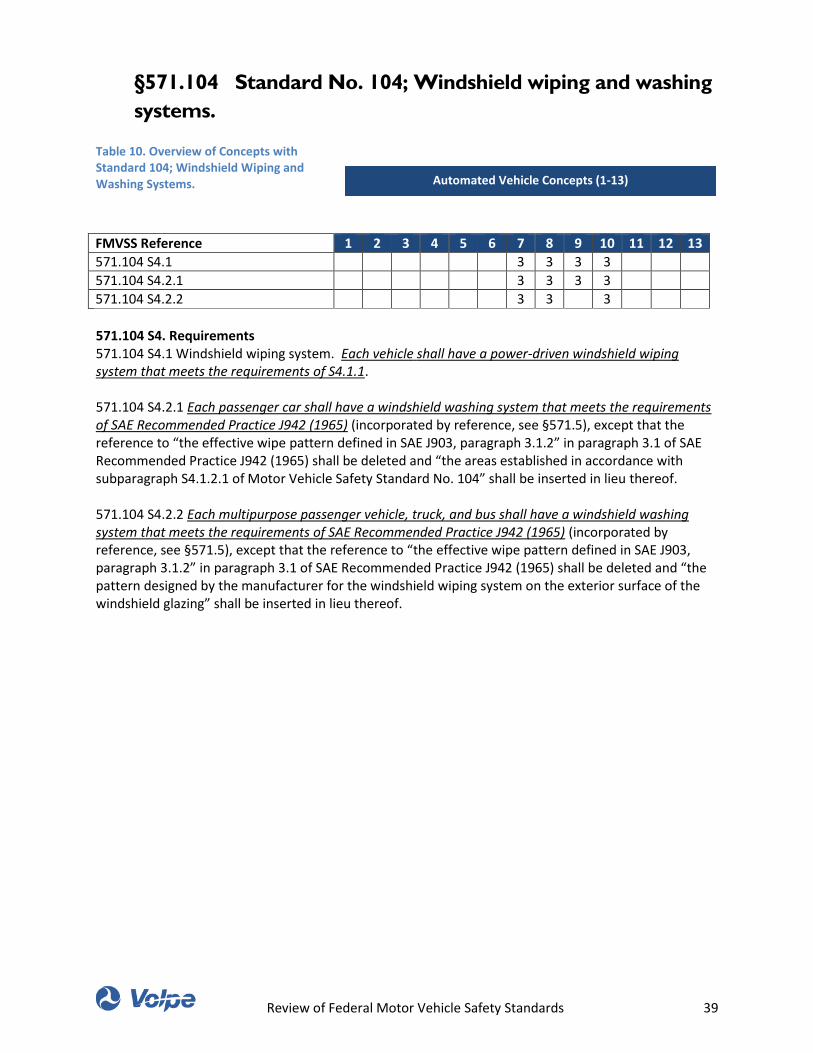
Review of Federal Motor Vehicle Safety Standards 39
§571.104 Standard No. 104; Windshield wiping and washing
systems.
Table 10. Overview of Concepts with Standard 104; Windshield Wiping and Washing Systems.
FMVSS Reference 1 2 3 4 5 6 7 8 9 10 11 12 13
571.104 S4.1 3 3 3 3
571.104 S4.2.1 3 3 3 3
571.104 S4.2.2 3 3 3
571.104 S4. Requirements 571.104 S4.1 Windshield wiping system. Each vehicle shall have a power-driven windshield wiping system that meets the requirements of S4.1.1. 571.104 S4.2.1 Each passenger car shall have a windshield washing system that meets the requirements of SAE Recommended Practice J942 (1965) (incorporated by reference, see §571.5), except that the reference to “the effective wipe pattern defined in SAE J903, paragraph 3.1.2” in paragraph 3.1 of SAE Recommended Practice J942 (1965) shall be deleted and “the areas established in accordance with subparagraph S4.1.2.1 of Motor Vehicle Safety Standard No. 104” shall be inserted in lieu thereof. 571.104 S4.2.2 Each multipurpose passenger vehicle, truck, and bus shall have a windshield washing system that meets the requirements of SAE Recommended Practice J942 (1965) (incorporated by reference, see §571.5), except that the reference to “the effective wipe pattern defined in SAE J903, paragraph 3.1.2” in paragraph 3.1 of SAE Recommended Practice J942 (1965) shall be deleted and “the pattern designed by the manufacturer for the windshield wiping system on the exterior surface of the windshield glazing” shall be inserted in lieu thereof.
Automated Vehicle Concepts (1-13)
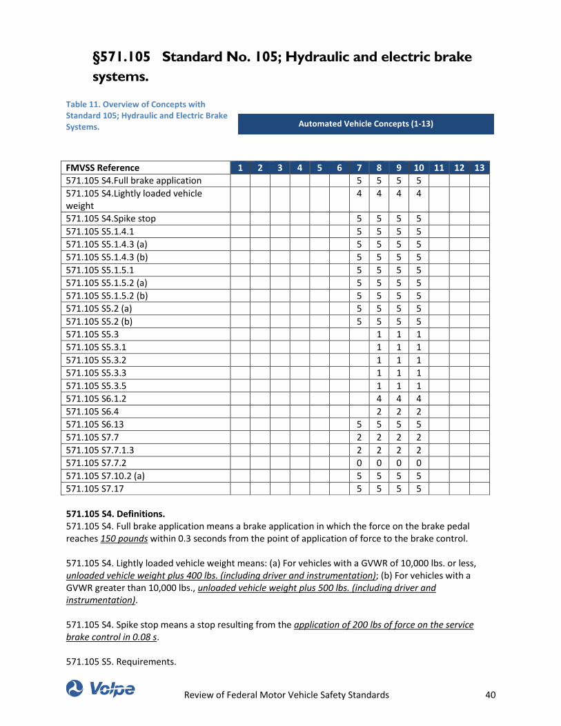
Review of Federal Motor Vehicle Safety Standards 40
§571.105 Standard No. 105; Hydraulic and electric brake
systems.
Table 11. Overview of Concepts with Standard 105; Hydraulic and Electric Brake Systems.
FMVSS Reference 1 2 3 4 5 6 7 8 9 10 11 12 13
571.105 S4.Full brake application 5 5 5 5
571.105 S4.Lightly loaded vehicle weight
4 4 4 4
571.105 S4.Spike stop 5 5 5 5
571.105 S5.1.4.1 5 5 5 5
571.105 S5.1.4.3 (a) 5 5 5 5
571.105 S5.1.4.3 (b) 5 5 5 5
571.105 S5.1.5.1 5 5 5 5
571.105 S5.1.5.2 (a) 5 5 5 5
571.105 S5.1.5.2 (b) 5 5 5 5
571.105 S5.2 (a) 5 5 5 5
571.105 S5.2 (b) 5 5 5 5
571.105 S5.3 1 1 1
571.105 S5.3.1 1 1 1
571.105 S5.3.2 1 1 1
571.105 S5.3.3 1 1 1
571.105 S5.3.5 1 1 1
571.105 S6.1.2 4 4 4
571.105 S6.4 2 2 2
571.105 S6.13 5 5 5 5
571.105 S7.7 2 2 2 2
571.105 S7.7.1.3 2 2 2 2
571.105 S7.7.2 0 0 0 0
571.105 S7.10.2 (a) 5 5 5 5
571.105 S7.17 5 5 5 5
571.105 S4. Definitions. 571.105 S4. Full brake application means a brake application in which the force on the brake pedal reaches 150 pounds within 0.3 seconds from the point of application of force to the brake control. 571.105 S4. Lightly loaded vehicle weight means: (a) For vehicles with a GVWR of 10,000 lbs. or less, unloaded vehicle weight plus 400 lbs. (including driver and instrumentation); (b) For vehicles with a GVWR greater than 10,000 lbs., unloaded vehicle weight plus 500 lbs. (including driver and instrumentation). 571.105 S4. Spike stop means a stop resulting from the application of 200 lbs of force on the service brake control in 0.08 s. 571.105 S5. Requirements.
Automated Vehicle Concepts (1-13)
Review of Federal Motor Vehicle Safety Standards 41
571.105 S5.1 Service brake systems. 571.105 S5.1.4 Fade and recovery. The service brakes shall be capable of stopping each vehicle in two fade and recovery tests as specified below. 571.105 S5.1.4.1 The control force used for the baseline check stops or snubs shall be not less than 10 pounds, nor more than 60 pounds, except that the control force for a vehicle with a GVWR of 10,000 pounds or more may be between 10 pounds and 90 pounds. 571.105 S1.4.3 (a) Each vehicle with a GVWR of 10,000 pounds or less shall be capable of making five recovery stops from 30 mph at 10 fpsps for each stop, with a control force application that falls within the following maximum and minimum limits: (1) A maximum for the first four recovery stops of 150 pounds, and for the fifth stop, of 20 pounds more than the average control force for the baseline check; and (2) A minimum of— (A) The average control force for the baseline check minus 10 pounds, or (B) The average control force for the baseline check times 0.60, whichever is lower (but in no case lower than 5 pounds). 571.105 S1.4.3 (b) Each vehicle with a GVWR of more than 10,000 pounds shall be capable of making five recovery snubs from 40 mph to 20 mph at 10 fpsps for each snub, with a control force application that falls within the following maximum and minimum limits: (1) A maximum for the first four recovery snubs of 150 pounds, and for the fifth snub, of 20 pounds more than the average control force for the baseline check (but in no case more than 100 pounds); and (2) A minimum of— (A) The average control force for the baseline check minus 10 pounds, or (B) The average control force for the baseline check times 0.60, whichever is lower (but in no case lower than 5 pounds). 571.105 S5.1.5 Water recovery. 571.105 S5.1.5.1 The control force used for the baseline check stops or snubs shall be not less than 10 pounds, nor more than 60 pounds, except that the control force for a vehicle with a GVWR of 10,000 pounds or more may be between 10 and 90 pounds. 571.105 S1.5.2 (a) After being driven for 2 minutes at a speed of 5 mph in any combination of forward and reverse directions through a trough having a water dept of 6 inches, each vehicle with a GVWR of 10,000 pounds or less shall be capable of making five recovery stops from 30 mph at ten fpsps for each stop with a control force application that falls within the following maximum and minimum limits: (1) A maximum for the first four recovery stops of 150 pounds, and for the fifth stop, of 45 pounds more than the average control force for the baseline check (but in no case more than 90 pounds, except that the maximum control force for the fifth stop in the case of a vehicle manufactured before September 1, 1976, shall be not more than plus 60 pounds of the average control force for the baseline check (but in no case more than 110 pounds). (2) A minimum of— (A) The average control force for the baseline check minus 10 pounds, or (B) The average control force for the baseline check times 0.60, whichever is lower (but in no case lower than 5 pounds). 571.105 S1.5.2 (b) After being driven for 2 minutes at a speed of 5 mph in any combination of forward and reverse directions through a trough having a water depth of 6 inches, each vehicle with a GVWR of more than 10,000 pounds shall be capable of making five recovery stops from 30 mph at 10 fpsps for each stop with a control force application that falls within the following maximum and minimum limits: (1) A maximum for the first four recovery stops of 150 pounds, and for the fifth stop, of 60 pounds more than the average control force for the baseline check (but in no case more than 110 pounds); and (2) A minimum of— (A) The average control force for the baseline check minus 10 pounds, or (B) The average control force for the baseline check times 0.60, whichever is lower (but in no case lower than 5 pounds). 571.105 S5.2 Parking Brake System
Review of Federal Motor Vehicle Safety Standards 42
571.105 S5.2 (a) In the case of a vehicle with a GVWR of 4,536 kilograms (10,000 pounds) or less, with a force applied to the control not to exceed 125 pounds for a foot-operated system and 90 pounds for a hand-operated system; and 571.105 S5.2 (b) In the case of a vehicle with a GVWR greater than 4,536 kilograms (10,000 pounds), with a force applied to the control not to exceed 150 pounds for a foot-operated system and 125 pounds for a hand-operated system. 571.105 S5.2.1 Except as provided in §5.2.2, the parking brake system on a passenger car and on a school bus with a GVWR of 10,000 pounds or less shall be capable of holding the vehicle stationary (to the limit of traction on the braked wheels) for 5 minutes in both a forward and reverse direction on a 30 percent grade. 571.105 S5.2.2 A vehicle of a type described in S5.2.1 at the option of the manufacturer may meet the requirements of S5.2.2.1, S5.2.2.2, and S5.2.2.3 instead of the requirements of S5.2.1 if: (a) The vehicle has a transmission or transmission control which incorporates a parking mechanism, and (b) The parking mechanism must be engaged before the ignition key can be removed. 571.105 S5.3 Brake system indicator lamp. Each vehicle shall have a brake system indicator lamp or lamps, mounted in front of and in clear view of the driver, which meet the requirements of S5.3.1 through S5.3.5. 571.105 S5.3.1 An indicator lamp shall be activated when the ignition (start) switch is in the “on” (“run”) position and whenever any of the conditions (a) or (b), (c), (d), (e), (f), and (g) occur: (a) A gross loss of pressure (such as caused by rupture of a brake line but not by a structural failure of a housing that is common to two or more subsystems) due to one of the following conditions (chosen at the option of the manufacturer): (1) Before or upon application of a differential pressure of not more than 225 lb/in2 between the active and failed brake system measured at a master cylinder outlet or a slave cylinder outlet. (2) Before or upon application of 50 pounds of control force upon a fully manual service brake. (3) Before or upon application of 25 pounds of control force upon a service brake with a brake power assist unit. (4) When the supply pressure in a brake power unit drops to a level not less than one-half of the normal system pressure. (b) A drop in the level of brake fluid in any master cylinder reservoir compartment to less than the recommended safe level specified by the manufacturer or to one-fourth of the fluid capacity of that reservoir compartment, whichever is greater. (c) A malfunction that affects the generation or transmission of response or control signals in an antilock brake system, or a total functional electrical failure in a variable proportioning brake system. (d) Application of the parking brake. (e) For a vehicle with electrically-actuated service brakes, failure of the source of electric power to the brakes, or diminution of state of charge of the batteries to less than a level specified by the manufacturer for the purpose of warning a driver of degraded brake performance. (f) For a vehicle with electric transmission of the service brake control signal, failure of a brake control circuit. (g) For an EV with RBS that is part of the service brake system, failure of the RBS. 571.105 S5.3.2 (a) Except as provided in paragraph (b) of this section, all indicator lamps shall be activated as a check of lamp function either when the ignition (start) switch is turned to the “on” (run) position when the engine is not running, or when the ignition (start) switch is in a position between “on” (run) and “start” that is designated by the manufacturer as a check position. (b) The indicator lamps need not be activated when a starter interlock is in operation. 571.105 S5.3.3 (a) Each indicator lamp activated due to a condition specified in S5.3.1 shall remain activated as long as the malfunction exists, whenever the ignition (start) switch is in the “on” (run) position, whether or not the engine is running. (b) For vehicles manufactured on and after September 1,
Review of Federal Motor Vehicle Safety Standards 43
1999 with GVWRs greater than 10,000 lbs, each message about the existence of a malfunction, as described in S5.3.1(c), shall be stored in the antilock brake system after the ignition switch is turned to the “off” position and the indicator lamp shall be automatically reactivated when the ignition switch is again turned to the “on” position. The indicator lamp shall also be activated as a check of lamp function whenever the ignition is turned to the “on” (run) position. The indicator lamp shall be deactivated at the end of the check of lamp function unless there is a malfunction or a message about a malfunction that existed when the key switch was last turned to the “off” position. 571.105 S5.3.5 (a) Each indicator lamp shall display word, words or abbreviation, in accordance with the requirements of Standard No. 101 (49 CFR 571.101) and/or this section, which shall have letters not less than 1⁄8 -inch high and be legible to the driver in daylight when lighted. Words in addition to those required by Standard No. 101 and/or this section and symbols may be provided for purposes of clarity. (b) If a single common indicator is used, the lamp shall display the word “Brake”. The letters and background of a single common indicator shall be of contrasting colors, one of which is red. (c)(1) If separate indicators are used for one or more of the conditions described in S5.3.1(a) through S5.3.1(g) of this standard, the indicator display shall include the word “Brake” and appropriate additional labeling, except as provided in (c)(1) (A) through (D) of this paragraph. (A) If a separate indicator lamp is provided for gross loss of pressure, the words “Brake Pressure” shall be used for S5.3.1(a). (B) If a separate indicator lamp is provided for low brake fluid, the words “Brake Fluid” shall be used for S5.3.1(b), except for vehicles using hydraulic system mineral oil. (C) If a separate indicator lamp is provided for an anti-lock system, the single word “Antilock” or “Anti-lock”, or the abbreviation “ABS”, may be used for S5.3.1(c). (D) If a separate indicator lamp is provided for application of the parking brake, the single word “Park” may be used for S5.3.1(d). (E) If a separate indicator is used for the regenerative brake system, the symbol “RBS” may be used. RBS failure may also be indicated by a lamp displaying the symbol “ABS/RBS.” (2) Except for a separate indicator lamp for an anti-lock system, a regenerative system, or an indicator for both anti-lock and regenerative system, the letters and background of each separate indicator lamp shall be of contrasting colors, one of which is red. The letters and background of a separate lamp for an anti-lock system, a regenerative system, or a lamp displaying both an anti-lock and a regenerative system shall be of contrasting colors, one of which is yellow. 571.105 S6 Test conditions. 571.105 S6.1 Vehicle weight. 571.105 S6.1.2 For applicable tests specified in S7.5(a), S7.7, S7.8, and S7.9, vehicle weight is lightly loaded vehicle weight, with the added weight, except for the roll bar structure allowed for trucks and buses with a GVWR greater than 10,000 pounds, distributed in the front passenger seat area in passenger cars, multipurpose passenger vehicles, and trucks, and in the area adjacent to the driver's seat in buses. 571.105 S6.2.5 For tests conducted “in neutral,” the operator of an EV with no “neutral” position (or other means such as a clutch for disconnecting the drive train from the propulsion motor(s)) does not apply any electromotive force to the propulsion motor(s). Any electromotive force that is applied to the propulsion motor(s) automatically remains in effect unless otherwise specified by the test procedure. 571.105 S6.4 Transmission selector control. For S7.3, S7.5, S7.8, S7.15, S7.17, S7.11.1.2, S7.11.2.2, S7.11.3.2, and as required for S7.13, the transmission selector control is in neutral for all decelerations. For all other tests during all decelerations, the transmission selector is in the control position, other than overdrive, recommended by the manufacturer for driving on a level surface at the applicable test speed. To avoid engine stall during tests required to be run in gear a manual transmission may be shifted to neutral (or the clutch disengaged) when the vehicle speed decreases to 20 mph. 571.105 S6.13 Control forces. Unless otherwise specified, the force applied to a brake control is not less than 15 lb and not more than 150 lb.
Review of Federal Motor Vehicle Safety Standards 44
571.105 S6.14 Special drive conditions. A vehicle with a GVWR greater than 10,000 pounds equipped with an interlocking axle system or a front wheel drive system that is engaged and disengaged by the driver is tested with the system disengaged. 571.105 S7. Test procedure and sequence. 571.105 S7.7 Parking brake test. The parking brake tests for any vehicle on different grades, in different directions, and for different loads may be conducted in any order. The force required for actuation of a hand-operated brake system shall be measured at the center of the hand grip area or at a distance of 11⁄2 inches from the end of the actuation lever, as illustrated in Figure II. 571.105 S7.1 Test procedure for requirements of S5.2.1 and S5.2.3. 571.105 S7.1.3 With the vehicle held stationary by means of the service brake control, apply the parking brake by a single application of the force specified in (a), (b), or (c) of this paragraph, except that a series of applications to achieve the specified force may be made in the case of a parking brake system design that does not allow the application of the specified force in a single application: (a) In the case of a passenger car or other vehicle with a GVWR of 10,000 lbs. or less, not more than 125 pounds for a foot-operated system, and not more than 90 pounds for a hand-operated system; and (b) In the case of a vehicle with a GVWR greater than 4,536 kilograms (10,000 pounds) not more than 150 pounds for a foot-operated system, and not more than 125 pounds for a hand-operated system. (c) For a vehicle using an electrically-activated parking brake, apply the parking brake by activating the parking brake control. 571.105 S7.7.2 Test procedure for requirements of S5.2.2 (a) Check that transmission must be placed in park position to release key; (b) Test as in S7.7.1, except in addition place the transmission control to engage the parking mechanism; and (c) Test as in S7.7.1 except on a 20 percent grade, with the parking mechanism not engaged. 571.105 S7.10 Service brake system 571.105 S7.10.2 Optional Procedures 571.105 S7.10.2 (a) (For vehicles with brake power assist units.) Disconnect the primary source of power. Make six stops each from 60 mph, to achieve the average deceleration for each stop as specified in table III. Apply the brake control as quickly as possible. Maintain control force until vehicle has stopped. At the completion of the stops specified above, deplete the system of any residual brake power reserve capability. Make one stop from 60 mph at an average deceleration of not lower than 7 fpsps for passenger cars (equivalent stopping distance 554 feet), or 6 fpsps for vehicles other than passenger cars (equivalent stopping distance 646 feet) and determine whether the control force exceeds 150 pounds. 571.105 S7.15 Service brake system—fourth effectiveness test. Repeat S7.5. Then (for passenger cars) make four stops from either 95 mph if the speed attainable in 2 mi is 99 to (but not including) 104 mph, or 100 mph if the speed attainable in 2 mi is 104 mph or greater. 571.105 S7.17 Spike stops. Make 10 successive spike stops from 30 mph with the transmission in neutral, with no reverse stops. Make spike stops by applying a control force of 200 lb while recording control force versus time. Maintain control force until vehicle has stopped. At completion of 10 spike stops, make six effectiveness stops from 60 mph.
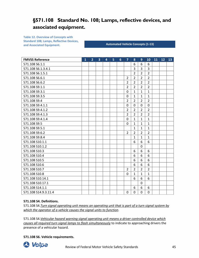
Review of Federal Motor Vehicle Safety Standards 45
§571.108 Standard No. 108; Lamps, reflective devices, and
associated equipment.
Table 12. Overview of Concepts with Standard 108; Lamps, Reflective Devices, and Associated Equipment.
FMVSS Reference 1 2 3 4 5 6 7 8 9 10 11 12 13
571.108 S6.1.1 6 6 6
571.108 S6.1.3.4.1 3 3 3
571.108 S6.1.5.1 2 2 2
571.108 S6.6.1 2 2 2 2
571.108 S6.6.2 2 2 2 2
571.108 S9.1.1 2 2 2 2
571.108 S9.3.1 0 1 1 1
571.108 S9.3.5 0 1 1 1
571.108 S9.4 2 2 2 2
571.108 S9.4.1.1 0 0 0 0
571.108 S9.4.1.2 2 2 2 2
571.108 S9.4.1.3 2 2 2 2
571.108 S9.4.1.4 0 1 1 1
571.108 S9.5 0 1 1 1
571.108 S9.5.1 1 1 1
571.108 S9.6.2 2 2 2 2
571.108 S9.8.4 1 1 1
571.108 S10.1.1 6 6 6
571.108 S10.1.2 0
571.108 S10.3 6 6 6
571.108 S10.4 6 6 6
571.108 S10.5 6 6 6
571.108 S10.6 6 6 6
571.108 S10.7 2 2 2 2
571.108 S10.8 0 1 1 1
571.108 S10.14.1 6 6 6
571.108 S10.17.1 0
571.108 S14.1.1 6 6 6
571.108 S14.9.3.11.4 0 0 0 0
571.108 S4. Definitions. 571.108 S4.Turn signal operating unit means an operating unit that is part of a turn signal system by which the operator of a vehicle causes the signal units to function. 571.108 S4.Vehicular hazard warning signal operating unit means a driver controlled device which causes all required turn signal lamps to flash simultaneously to indicate to approaching drivers the presence of a vehicular hazard.
571.108 S6. Vehicle requirements.
Automated Vehicle Concepts (1-13)
Review of Federal Motor Vehicle Safety Standards 46
571.108 S6.1 Required lamps, reflective devices, and associated equipment by vehicle type.
571.108 S6.1.1 Quantity. Except as provided in succeeding paragraphs of this S6.1.1 each vehicle must
be equipped with at least the number of lamps, reflective devices, and items of associated equipment
specified for that vehicle type and size in Table I and Section 6.6, designed to conform to the
requirements of this standard. Multiple license plate lamps and backup lamps may be used to fulfill
photometric requirements for those functions.
571.108 S6.1.3 Mounting location.
571.108 S6.1.3.4 High mounted stop lamps.
571.108 S6.1.3.4.1 Interior mounting. A high-mounted stop lamp mounted inside the vehicle must have
means provided to minimize reflections from the light of the lamp upon the rear window glazing that
might be visible to the driver when viewed directly, or indirectly in the rearview mirror.
571.108 S6.1.5.1 Hazard warning signal. In all passenger cars, multipurpose passenger vehicles, trucks,
and buses, the activation of the vehicular hazard warning signal operating unit must cause to flash
simultaneously sufficient turn signal lamps to meet, as a minimum, the turn signal photometric
requirements of this standard.
571.108 S6.6 Associated equipment.
571.108 S6.6.1 All vehicles to which this standard applies, except trailers, must be equipped with a turn
signal operating unit, a turn signal flasher, a turn signal pilot indicator, a headlamp beam switching
device, and an upper beam headlamp indicator meeting the requirements of S9.
571.108 S6.6.2 All vehicles to which this standard applies except trailers and motorcycles must be
equipped with a vehicular hazard warning operating unit, a vehicular hazard warning signal flasher, and
a vehicular hazard warning signal pilot indicator meeting the requirements of S9.
571.108 S9. Associated equipment requirements.
571.108 S9.1 Turn signal operating units.
571.108 S9.1.1 The turn signal operating unit installed on passenger cars, multipurpose passenger
vehicles, trucks, and buses less than 2032 mm in overall width must be self-canceling by steering wheel
rotation and capable of cancellation by a manually operated control.
571.108 S9.3 Turn signal pilot indicator.
571.108 S9.3.1 Each vehicle equipped with a turn signal operating unit where any turn signal lamp is not
visible to the driver must also have an illuminated pilot indicator to provide a clear and unmistakable
indication that the turn signal system is activated.
571.108 S9.3.5 The minimum required illuminated area of the indicator must be visible to any tangent on
the 95th eyellipse as defined in SAE Recommended Practice J941b (1969) (incorporated by reference, see
§571.5), with the steering wheel turned to a straight ahead driving position and in the design location for
an adjustable wheel or column.
571.108 S9.4 Headlamp beam switching device. Each vehicle must have a means of switching between
Review of Federal Motor Vehicle Safety Standards 47
lower and upper beams designed and located so that it may be operated conveniently by a simple
movement of the driver's hand or foot. The switch must have no dead point and, except as provided by
S6.1.5.2, the lower and upper beams must not be energized simultaneously except momentarily for
temporary signaling purposes or during switching between beams.
571.108 S9.4.1 Semi-automatic headlamp beam switching device. As an alternative to S9.4, a vehicle
may be equipped with a semi-automatic means of switching between lower and upper beams.
571.108 S9.4.1.1 Operating instructions. Each semi-automatic headlamp switching device must include
operating instructions to permit a driver to operate the device correctly including; how to turn the
automatic control on and off, how to adjust the provided sensitivity control, and any other specific
instructions applicable to the particular device.
571.108 S9.4.1.2 Manual override. The device must include a means convenient to the driver for
switching to the opposite beam from the one provided.
571.108 S9.4.1.3 Fail safe operation. A failure of the automatic control portion of the device must not
result in the loss of manual operation of both upper and lower beams.
571.108 S9.4.1.4 Automatic dimming indicator. There must be a convenient means of informing the
driver when the device is controlling the headlamps automatically. The device shall not affect the
function of the upper beam indicator light.
571.108 S9.5 Upper beam headlamp indicator. Each vehicle must have a means for indicating to the
driver when the upper beams of the headlighting system are activated.
571.108 S9.5.1 Indicator size and location. The upper beam headlamp indicator must have a minimum
area equivalent to that of a 3⁄16 in diameter circle, and be plainly visible to drivers of all heights under
normal driving conditions when headlamps are required.
571.108 S9.6 Vehicular hazard warning signal operating unit.
571.108 S9.6.2 Operating unit switch. The unit must operate independently of the ignition or equivalent
switch. If the actuation of the hazard function requires the operation of more than one switch, a means
must be provided for actuating all switches simultaneously by a single driver action.
571.108 S9.8 Vehicular hazard warning signal pilot indicator.
571.108 S9.8.4 Indicator size and color. If the vehicular hazard warning signal pilot indicator is not
combined with the turn signal pilot indicator, it must emit a red color and have a minimum area
equivalent to a 0.5 in diameter circle.
571.108 S10 Headlight system requirements.
571.108 S10.1 Vehicle headlighting systems.
571.108 S10.1.1 Each passenger car, multipurpose passenger vehicle, truck and bus must be equipped
with a headlighting system conforming to the requirements of Table II and this standard.
Review of Federal Motor Vehicle Safety Standards 48
571.108 S10.1.2 Each motorcycle must be equipped with a headlighting system conforming to S10.17 of
this standard.
571.108 S10.3 Number. See Tables I-a and I-c.
571.108 S10.4 Color of light. See Tables I-a and I-c.
571.108 S10.5 Mounting location. See Tables I-a and I-c and S6.1.3.5.
571.108 S10.6 Mounting height. See Tables I-a and I-c.
571.108 S10.7 Activation. See Tables I-a and I-c, Table II, and S6.1.5.
571.108 S10.10 Indicator. See S9.5.
571.108 S10.14 Integral beam headlighting systems. All integral beam headlighting systems must be of a
type designated in Table II-c.
571.108 S10.14.1 Installation. An integral beam headlighting system must consist of the correct number
of designated headlamp units as specified for the applicable system in Table II-c. The units must have
their beams activated as specified in Table II-c. A system must provide in total not more than two upper
beams and two lower beams.
571.108 S10.17 Motorcycle headlighting systems.
571.108 S10.17.1 Installation. The headlighting system installed on a motorcycle must consist of one of
the system types specified in this paragraph, and must be located on the front.
571.108 S10.17.1.1 Single headlamp.
571.108 S10.17.1.2 Two headlamps with both beams.
571.108 S10.17.1.3 Two headlamps, upper beam and lower beam.
571.108 S12 Headlamp concealment device requirements.
571.108 S12.5 Except for cases of malfunction covered by S12.2, each headlamp concealment device
must, within an ambient temperature range of −20 °F to +120 °F, be capable of being fully opened in not
more than 3 seconds after the actuation of a driver-operated control.
571.108 S14. Physical and photometry test procedures and performance requirements.
571.108 S14.1 General test procedures and performance requirements.
571.108 S14.1.1 Each lamp, reflective device, item of conspicuity treatment, and item of associated
equipment required or permitted by this standard must be designed to conform to all applicable physical
test performance requirements specified for it.
571.108 S14.9.3.11 Semiautomatic headlamp beam switching device tests.
571.108 S14.9.3.11.4 Manual override test. 571.108 S14.9.3.11.4.1.3 The manufacturer's instructions are
Review of Federal Motor Vehicle Safety Standards 49
followed to cause the device to override the test light and switch to upper beam. 571.108
S14.9.3.11.4.1.4 In a similar manner, the test light is extinguished to cause the device to switch to the
upper beam mode. 571.108 S14.9.3.11.4.1.5 Again the manufacturer's instructions are followed to
cause the device to switch to lower beam.
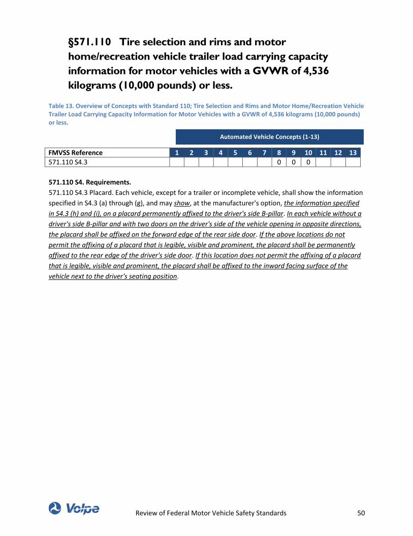
Review of Federal Motor Vehicle Safety Standards 50
§571.110 Tire selection and rims and motor
home/recreation vehicle trailer load carrying capacity
information for motor vehicles with a GVWR of 4,536
kilograms (10,000 pounds) or less.
Table 13. Overview of Concepts with Standard 110; Tire Selection and Rims and Motor Home/Recreation Vehicle Trailer Load Carrying Capacity Information for Motor Vehicles with a GVWR of 4,536 kilograms (10,000 pounds) or less.
FMVSS Reference 1 2 3 4 5 6 7 8 9 10 11 12 13
571.110 S4.3 0 0 0
571.110 S4. Requirements.
571.110 S4.3 Placard. Each vehicle, except for a trailer or incomplete vehicle, shall show the information
specified in S4.3 (a) through (g), and may show, at the manufacturer's option, the information specified
in S4.3 (h) and (i), on a placard permanently affixed to the driver's side B-pillar. In each vehicle without a
driver's side B-pillar and with two doors on the driver's side of the vehicle opening in opposite directions,
the placard shall be affixed on the forward edge of the rear side door. If the above locations do not
permit the affixing of a placard that is legible, visible and prominent, the placard shall be permanently
affixed to the rear edge of the driver's side door. If this location does not permit the affixing of a placard
that is legible, visible and prominent, the placard shall be affixed to the inward facing surface of the
vehicle next to the driver's seating position.
Automated Vehicle Concepts (1-13)
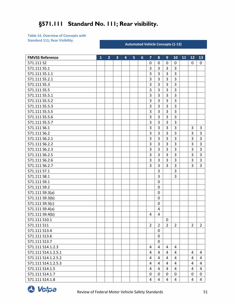
Review of Federal Motor Vehicle Safety Standards 51
§571.111 Standard No. 111; Rear visibility.
Table 14. Overview of Concepts with Standard 111; Rear Visibility.
FMVSS Reference 1 2 3 4 5 6 7 8 9 10 11 12 13
571.111 S2 0 0 0 0 0 0
571.111 S5.1 3 3 3 3
571.111 S5.1.1 3 3 3 3
571.111 S5.2.1 3 3 3 3
571.111 S5.3 3 3 3 3
571.111 S5.5 3 3 3 3
571.111 S5.5.1 3 3 3 3
571.111 S5.5.2 3 3 3 3
571.111 S5.5.3 3 3 3 3
571.111 S5.5.5 3 3 3 3
571.111 S5.5.6 3 3 3 3
571.111 S5.5.7 3 3 3 3
571.111 S6.1 3 3 3 3 3 3
571.111 S6.2 3 3 3 3 3 3
571.111 S6.2.1 3 3 3 3 3 3
571.111 S6.2.2 3 3 3 3 3 3
571.111 S6.2.3 3 3 3 3 3 3
571.111 S6.2.5 3 3 3 3 3 3
571.111 S6.2.6 3 3 3 3 3 3
571.111 S6.2.7 3 3 3 3 3 3
571.111 S7.1 3 3
571.111 S8.1 3 3
571.111 S9.1 0
571.111 S9.2 0
571.111 S9.3(a) 0
571.111 S9.3(b) 0
571.111 S9.3(c) 0
571.111 S9.4(a) 4
571.111 S9.4(b) 4 4
571.111 S10.1 0
571.111 S11 2 2 2 2 2 2
571.111 S13.4 0
571.111 S13.6 0
571.111 S13.7 0
571.111 S14.1.2.3 4 4 4 4
571.111 S14.1.2.5.1 4 4 4 4 4 4
571.111 S14.1.2.5.2 4 4 4 4 4 4
571.111 S14.1.2.5.3 4 4 4 4 4 4
571.111 S14.1.5 4 4 4 4 4 4
571.111 S14.1.7 0 0 0 0 0 0
571.111 S14.1.8 4 4 4 4 4 4
Automated Vehicle Concepts (1-13)
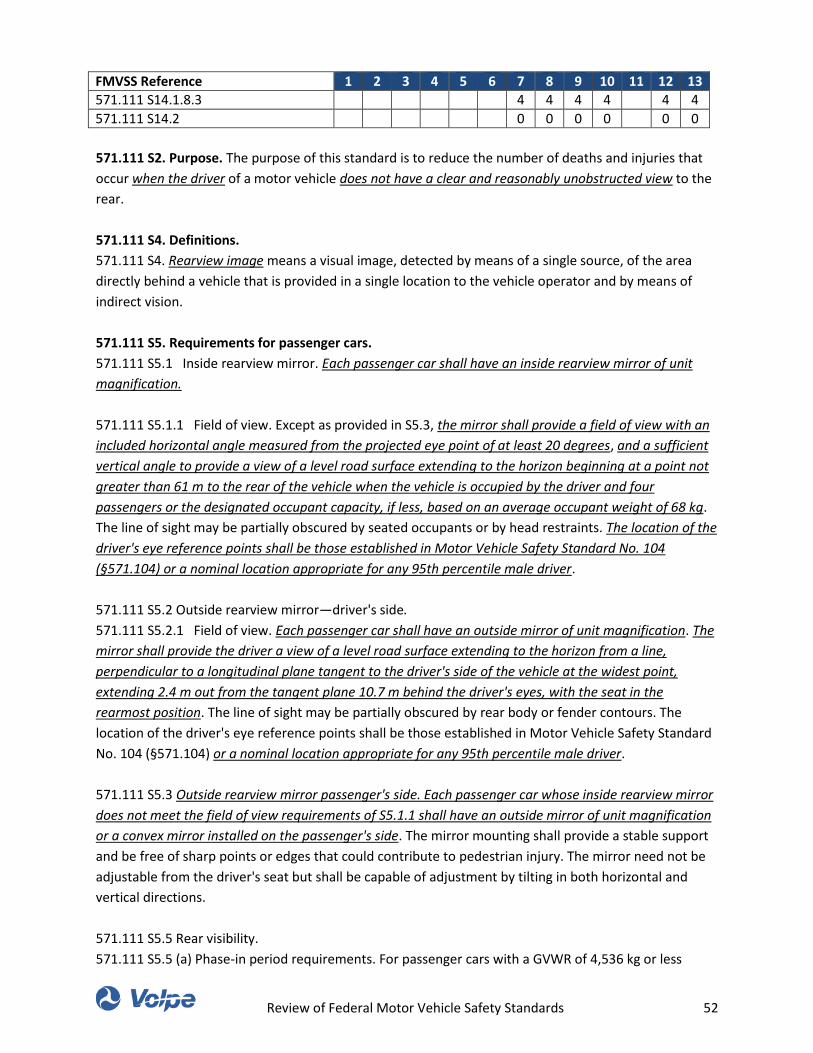
Review of Federal Motor Vehicle Safety Standards 52
FMVSS Reference 1 2 3 4 5 6 7 8 9 10 11 12 13
571.111 S14.1.8.3 4 4 4 4 4 4
571.111 S14.2 0 0 0 0 0 0
571.111 S2. Purpose. The purpose of this standard is to reduce the number of deaths and injuries that
occur when the driver of a motor vehicle does not have a clear and reasonably unobstructed view to the
rear.
571.111 S4. Definitions.
571.111 S4. Rearview image means a visual image, detected by means of a single source, of the area
directly behind a vehicle that is provided in a single location to the vehicle operator and by means of
indirect vision.
571.111 S5. Requirements for passenger cars.
571.111 S5.1 Inside rearview mirror. Each passenger car shall have an inside rearview mirror of unit
magnification.
571.111 S5.1.1 Field of view. Except as provided in S5.3, the mirror shall provide a field of view with an
included horizontal angle measured from the projected eye point of at least 20 degrees, and a sufficient
vertical angle to provide a view of a level road surface extending to the horizon beginning at a point not
greater than 61 m to the rear of the vehicle when the vehicle is occupied by the driver and four
passengers or the designated occupant capacity, if less, based on an average occupant weight of 68 kg.
The line of sight may be partially obscured by seated occupants or by head restraints. The location of the
driver's eye reference points shall be those established in Motor Vehicle Safety Standard No. 104
(§571.104) or a nominal location appropriate for any 95th percentile male driver.
571.111 S5.2 Outside rearview mirror—driver's side.
571.111 S5.2.1 Field of view. Each passenger car shall have an outside mirror of unit magnification. The
mirror shall provide the driver a view of a level road surface extending to the horizon from a line,
perpendicular to a longitudinal plane tangent to the driver's side of the vehicle at the widest point,
extending 2.4 m out from the tangent plane 10.7 m behind the driver's eyes, with the seat in the
rearmost position. The line of sight may be partially obscured by rear body or fender contours. The
location of the driver's eye reference points shall be those established in Motor Vehicle Safety Standard
No. 104 (§571.104) or a nominal location appropriate for any 95th percentile male driver.
571.111 S5.3 Outside rearview mirror passenger's side. Each passenger car whose inside rearview mirror
does not meet the field of view requirements of S5.1.1 shall have an outside mirror of unit magnification
or a convex mirror installed on the passenger's side. The mirror mounting shall provide a stable support
and be free of sharp points or edges that could contribute to pedestrian injury. The mirror need not be
adjustable from the driver's seat but shall be capable of adjustment by tilting in both horizontal and
vertical directions.
571.111 S5.5 Rear visibility.
571.111 S5.5 (a) Phase-in period requirements. For passenger cars with a GVWR of 4,536 kg or less
Review of Federal Motor Vehicle Safety Standards 53
manufactured on or after May 1, 2016, but not later than April 30, 2018, a percentage of each
manufacturer's production, as specified in S15, shall display a rearview image meeting the requirements
of S5.5.1. (b) Final requirements. Each passenger car with a GVWR of 4,536 kg or less manufactured on
or after May 1, 2018, shall display a rearview image meeting the requirements of S5.5.1 through S5.5.7.
571.111 S5.5.1 Field of view. When tested in accordance with the procedures in S14.1, the rearview
image shall include: (a) A minimum of a 150-mm wide portion along the circumference of each test
object located at positions F and G specified in S14.1.4; and (b) The full width and height of each test
object located at positions A through E specified in S14.1.4.
571.111 S5.5.2 Size. When the rearview image is measured in accordance with the procedures in S14.1,
the calculated visual angle subtended by the horizontal width of (a) All three test objects located at
positions A, B, and C specified in S14.1.4 shall average not less than 5 minutes of arc; and (b) Each
individual test object (A, B, and C) shall not be less than 3 minutes of arc.
571.111 S5.5.3 Response time. The rearview image meeting the requirements of S5.5.1 and S5.5.2, when
tested in accordance with S14.2, shall be displayed within 2.0 seconds of the start of a backing event.
571.111 S5.5.5 Deactivation. The rearview image meeting the requirements of S5.5.1 and S5.5.2 shall
remain visible during the backing event until either, the driver modifies the view, or the vehicle direction
selector is removed from the reverse position.
571.111 S5.5.6 Default view. The rear visibility system must default to the rearview image meeting the
requirements of S5.5.1 and S5.5.2 at the beginning of each backing event regardless of any modifications
to the field of view the driver has previously selected.
571.111 S5.5.7 Durability. The rear visibility system shall meet the field of view and image size
requirements of S5.5.1 and S5.5.2 after each durability test specified in S14.3.1, S14.3.2, and S14.3.3.
571.111 S6. Requirements for multipurpose passenger vehicles, low-speed vehicles, trucks, buses, and
school buses with GVWR of 4,536 kg or less.
571.111 S6.1. Each multipurpose passenger vehicle, truck and bus, other than a school bus, with a
GVWR of 4,536 kg or less shall have either—(a) Mirrors that conform to the requirements of S5.; or (b)
Outside mirrors of unit magnification, each with not less than 126 cm2 of reflective surface, installed
with stable supports on both sides of the vehicle, located so as to provide the driver a view to the rear
along both sides of the vehicle, and adjustable in both the horizontal and vertical directions to view the
rearward scene.
571.111 S6.2 Rear visibility. (a) Phase-in period requirements. For multipurpose passenger vehicles, low-
speed vehicles, trucks, buses, and school buses with a GVWR of 4,536 kg or less manufactured on or
after May 1, 2016, but not later than April 30, 2018, a percentage of each manufacturer's production, as
specified in S15, shall display a rearview image meeting the requirements of S6.2.1. (b) Final
requirements. Each multipurpose passenger vehicle, low-speed vehicle, truck, bus, and school bus with a
GVWR of 4,536 kg or less manufactured on or after May 1, 2018, shall display a rearview image meeting
Review of Federal Motor Vehicle Safety Standards 54
the requirements of S6.2.1 through S6.2.7.
571.111 S6.2.1 Field of view. When tested in accordance with the procedures in S14.1, the rearview
image shall include: (a) A minimum of a 150-mm wide portion along the circumference of each test
object located at positions F and G specified in S14.1.4; and (b) The full width and height of each test
object located at positions A through E specified in S14.1.4.
571.111 S6.2.2 Size. When the rearview image is measured in accordance with the procedures in S14.1,
the calculated visual angle subtended by the horizontal width of (a) All three test objects located at
positions A, B, and C specified in S14.1.4 shall average not less than 5 minutes of arc; and (b) Each
individual test object (A, B, and C) shall not be less than 3 minutes of arc.
571.111 S6.2.3 Response time. The rearview image meeting the requirements of S6.2.1 and S6.2.2, when
tested in accordance with S14.2, shall be displayed within 2.0 seconds of the start of a backing event.
571.111 S6.2.5 Deactivation. The rearview image meeting the requirements of S6.2.1 and S6.2.2 shall
remain visible during the backing event until either, the driver modifies the view, or the vehicle direction
selector is removed from the reverse position.
571.111 S6.2.6 Default view. The rear visibility system must default to the rearview image meeting the
requirements of S6.2.1 and S6.2.2 at the beginning of each backing event regardless of any modifications
to the field of view the driver has previously selected.
571.111 S6.2.7 Durability. The rear visibility system shall meet the field of view and image size
requirements of S6.2.1 and S6.2.2 after each durability test specified in S14.3.1, S14.3.2, and S14.3.3.
571.111 S7. Requirements for multipurpose passenger vehicles and trucks with a GVWR of more than
4,536 kg and less than 11,340 kg and buses, other than school buses, with a GVWR of more than 4,536
kg.
571.111 S7.1 Each multipurpose passenger vehicle and truck with a GVWR of more than 4,536 kg and
less than 11,340 kg and each bus, other than a school bus, with a GVWR of more than 4,536 kg shall
have outside mirrors of unit magnification, each with not less than 323 cm2 of reflective surface,
installed with stable supports on both sides of the vehicle. The mirrors shall be located so as to provide
the driver a view to the rear along both sides of the vehicle and shall be adjustable both in the horizontal
and vertical directions to view the rearward scene.
571.111 S8. Requirements for multipurpose passenger vehicles and trucks with a GVWR of 11,340 kg
or more.
571.111 S8.1 Each multipurpose passenger vehicle and truck with a GVWR of 11,340 kg or more shall
have outside mirrors of unit magnification, each with not less than 323 cm2 of reflective surface, installed
with stable supports on both sides of the vehicle. The mirrors shall be located so as to provide the driver
a view to the rear along both sides of the vehicle and shall be adjustable both in the horizontal and
vertical directions to view the rearward scene.
Review of Federal Motor Vehicle Safety Standards 55
571.111 S9. Requirements for School Buses. When a school bus is tested in accordance with the
procedures of S13, it shall meet the requirements of S9.1 through S9.4.
571.111 S9.1 Outside Rearview Mirrors. Each school bus shall have two outside rearview mirror
systems: System A and System B.
571.111 S9.2 System A shall be located with stable supports so that the portion of the system on the
bus's left side, and the portion on its right side, each: (a) Includes at least one mirror of unit
magnification with not less than 323 cm2 of reflective surface; and (b) Includes one or more mirrors
which together provide, at the driver's eye location, a view of: (1) For the mirror system on the right side
of the bus, the entire top surface of cylinder N in Figure 2, and that area of the ground which extends
rearward from cylinder N to a point not less than 61 meters from the mirror surface. (2) For the mirror
system on the left side of the bus, the entire top surface of cylinder M in Figure 2, and that area of the
ground which extends rearward from cylinder M to a point not less than 61 meters from the mirror
surface.
571.111 S9.3(a) For each of the cylinders A through P whose entire top surface is not directly visible
from the driver's eye location, System B shall provide, at that location: (1) A view of the entire top
surface of that cylinder. (2) A view of the ground that overlaps with the view of the ground provided by
System A.
571.111 S9.3(b) Each mirror installed in compliance with S9.3(a) shall meet the following requirements:
(1) Each mirror shall have a projected area of at least 258 cm2, as measured on a plane at a right angle
to the mirror's axis. (2) Each mirror shall be located such that the distance from the center point of the
eye location of a 25th percentile adult female seated in the driver's seat to the center of the mirror shall
be at least 95 cm. (3) Each mirror shall have no discontinuities in the slope of the surface of the mirror.
(4) Each mirror shall be installed with a stable support.
571.111 S9.3(c) Each school bus which has a mirror installed in compliance with S9.3(a) that has an
average radius of curvature of less than 889 mm, as determined under S12, shall have a label visible to
the seated driver. The label shall be printed in a type face and color that are clear and conspicuous. The
label shall state the following: “USE CROSS VIEW MIRRORS TO VIEW PEDESTRIANS WHILE BUS IS
STOPPED. DO NOT USE THESE MIRRORS TO VIEW TRAFFIC WHILE BUS IS MOVING. IMAGES IN SUCH
MIRRORS DO NOT ACCURATELY SHOW ANOTHER VEHICLE'S LOCATION.”
571.111 S9.4(a) Each image required by S9.3(a)(1) to be visible at the driver's eye location shall be
separated from the edge of the effective mirror surface of the mirror providing that image by a distance
of not less than 3 minutes of arc.
571.111 S9.4(b) The image required by S9.3(a)(1) of cylinder P shall meet the following requirements: (1)
The angular size of the shortest dimension of that cylinder's image shall be not less than 3 minutes of
arc; and (2) The angular size of the longest dimension of that cylinder's image shall be not less than 9
minutes of arc.
571.111 S10. Requirements for motorcycles.
Review of Federal Motor Vehicle Safety Standards 56
571.111 S10.1 Each motorcycle shall have either a mirror of unit magnification with not less than 8065
mm2 of reflective surface, or a convex mirror with not less than 6450 mm2 of reflective surface and an
average radius of curvature not less than 508 mm and not greater than 1524 mm, installed with a stable
support, and mounted so that the horizontal center of the reflective surface is at least 279 mm outward
of the longitudinal centerline of the motorcycle. The mirror shall be adjustable by tilting in both the
horizontal and vertical directions.
571.111 S11. Mirror Construction. The average reflectance of any mirror required by this standard shall
be determined in accordance with SAE Standard J964 OCT84 (incorporated by reference, see §571.5). All
single reflectance mirrors shall have an average reflectance of at least 35 percent. If a mirror is capable
of multiple reflectance levels, the minimum reflectance level in the day mode shall be at least 35
percent and the minimum reflectance level in the night mode shall be at least 4 percent. A multiple
reflectance mirror shall either be equipped with a means for the driver to adjust the mirror to a
reflectance level of at least 35 percent in the event of electrical failure, or achieve such reflectance level
automatically in the event of electrical failure.
571.111 S13. School bus mirror test procedures. The requirements of S9.1 through S9.4 shall be met
when the vehicle is tested in accordance with the following conditions.
571.111 S13.4 The driver's eye location is the eye location of a 25th percentile adult female, when
seated in the driver's seat as follows: (a) The center point of the driver's eye location is the point located
68.58 centimeters (27 inches) vertically above the intersection of the seat cushion and the seat back at
the longitudinal centerline of the seat. (b) Adjust the driver's seat to the midway point between the
forward-most and rear-most positions, and if separately adjustable in the vertical direction, adjust to the
lowest position. If an adjustment position does not exist at the midway point, use the closest
adjustment position to the rear of the midpoint. If a seat back is adjustable, adjust the seat back angle to
the manufacturer's nominal design riding position in accordance with the manufacturer's
recommendations.
571.111 S13.6 Place a 35 mm or larger format camera, or video camera, so that its image plane is
located at the center point of the driver's eye location or at any single point within a semicircular area
established by a 15.24 centimeter (6 inch) radius parallel to and forward of the center point (see figure
3). With the camera at any single location on or within that semicircle look through the camera and the
windows of the bus and determine whether the entire top surface of each cylinder is directly visible.
571.111 S13.7 For each cylinder whose entire top surface is determined under paragraph 13.4 of this
section not to be directly visible at the driver's eye location, (a) Place a comparison chart (see figure 4)
above the mirror that provides the fullest view of the cylinder in situations where a cylinder is partially
visible through more than one mirror. The width of the bars in Figure 4 indicating three minutes of arc
and nine minutes of arc are derived from the following formula: For 3 minutes of arc: X=D×0.000873,
Where: X=the width of a line, in the unit of measurement D, representing 3 minutes of arc; D=distance
from center point of driver's eye location to the center of the mirror's surface; and 0.000873=tangent of 3
minutes of arc. For 9 minutes of arc: X=D×0.002618, Where: X=the width of a line, in the unit of
measurement D, representing 9 minutes of arc; D=distance from center point of driver's eye location to
the center of the mirror's surface; and 0.002618=tangent of 9 minutes of arc.
Review of Federal Motor Vehicle Safety Standards 57
571.111 S14. Rear visibility test procedure.
571.111 S14.1 Field of view and image size test procedure.
571.111 S14.1.2 Vehicle conditions.
571.111 S14.1.2.3 Vehicle load. The vehicle is loaded to simulate the weight of the driver and four
passengers or the designated occupant capacity, if less. The weight of each occupant is represented by
45 kg resting on the seat pan and 23 kg resting on the vehicle floorboard placed in the driver's
designated seating position and any other available designated seating position.
571.111 S14.1.2.5 Driver’s seat positioning.
571.111 S14.1.2.5.1 Adjust the driver's seat to the midpoint of the longitudinal adjustment range. If the
seat cannot be adjusted to the midpoint of the longitudinal adjustment range, the closest adjustment
position to the rear of the midpoint shall be used.
571.111 S14.1.2.5.2 Adjust the driver's seat to the lowest point of all vertical adjustment ranges present.
571.111 S14.1.2.5.3 Using the three dimensional SAE Standard J826 JUL95 (incorporated by reference,
see §571.5) manikin, adjust the driver's seat back angle at the vertical portion of the H-point machine's
torso weight hanger to 25 degrees. If this adjustment setting is not available, adjust the seat-back angle
to the positional detent setting closest to 25 degrees in the direction of the manufacturer's nominal
design riding position.
571.111 S14.1.5 Test reference point. Obtain the test reference point using the following procedure. (a)
Locate the center of the forward-looking eye midpoint (Mf) illustrated in Figure 6 so that it is 635 mm
vertically above the H point (H) and 96 mm aft of the H point. (b) Locate the head/neck joint center (J)
illustrated in Figure 6 so that it is 100 mm rearward of Mf and 588 mm vertically above the H point. (c)
Draw an imaginary horizontal line between Mf and a point vertically above J, defined as J2. (d) Rotate
the imaginary line about J2 in the direction of the rearview image until the straight-line distance
between Mf and the center of the display used to present the rearview image required in this standard
reaches the shortest possible value. (e) Define this new, rotated location of Mf to be Mr (eye midpoint
rotated).
571.111 S14.1.7 Steering wheel adjustment. The steering wheel is adjusted to the position where the
longitudinal centerline of all vehicle tires are parallel to the longitudinal centerline of the vehicle. If no
such position exists, adjust the steering wheel to the position where the longitudinal centerline of all
vehicle tires are closest to parallel to the longitudinal centerline of the vehicle.
571.111 S14.1.8 Measurement procedure. (a) Locate a 35 mm or larger format still camera, video
camera, or digital equivalent such that the center of the camera's image plane is located at Mr and the
camera lens is directed at the center of the display's rearview image. (b) Affix a ruler at the base of the
rearview image in an orientation perpendicular with a test object cylinder centerline. If the vehicle head
restraints obstruct the camera's view of the display, they may be adjusted or removed. (c) Photograph
the image of the visual display with the ruler included in the frame and the rearview image displayed.
Review of Federal Motor Vehicle Safety Standards 58
571.111 S14.1.8.3 Determine viewing distance. Determine the actual distance from the rotated eye
midpoint location (Mr) to the center of the rearview image. Define this viewing distance as aeye.
571.111 S14.2 Image response time test procedure. The temperature inside the vehicle during this test
is any temperature between 15 °C and 25 °C. Immediately prior to commencing the actions listed in
subparagraphs (a)-(c) of this paragraph, all components of the rear visibility system are in a powered off
state. Then: (a) Open the driver's door to any width, (b) Close the driver's door (c) Activate the starting
system using the key, and (d) Select the vehicle's reverse direction at any time not less than 4.0 seconds
and not more than 6.0 seconds after the driver's door is opened. The driver door is open when the edge
of the driver's door opposite of the door's hinge is no longer flush with the exterior body panel.
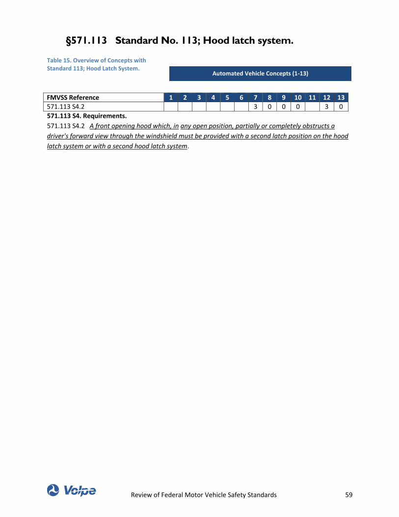
Review of Federal Motor Vehicle Safety Standards 59
§571.113 Standard No. 113; Hood latch system.
Table 15. Overview of Concepts with Standard 113; Hood Latch System.
FMVSS Reference 1 2 3 4 5 6 7 8 9 10 11 12 13
571.113 S4.2 3 0 0 0 3 0
571.113 S4. Requirements.
571.113 S4.2 A front opening hood which, in any open position, partially or completely obstructs a
driver's forward view through the windshield must be provided with a second latch position on the hood
latch system or with a second hood latch system.
Automated Vehicle Concepts (1-13)

Review of Federal Motor Vehicle Safety Standards 60
§571.114 Standard No. 114; Theft protection and rollaway
prevention.
Table 16. Overview of Concepts with Standard 114; Theft Protection and Rollaway Prevention.
FMVSS Reference 1 2 3 4 5 6 7 8 9 10 11 12 13
571.114 S4 0 0 0 0 0 0
571.114 S5.1.1 0 0 0 0
571.114 S5.1.3 1 1 1 1
571.114 S5.2.1 3 3 3 3
571.114 S5.2.2 6 6 6 6 6
571.114 S5.2.3 6 6 6 6 6
571.114 S5.2.4 6 6 6 6 6
571.114 S5.3 4 4 4 4 4 4 4
571.114 S6.1.1 4 4 4
571.114 S6.1.2 4 4 4 4 4 4
571.114 S6.2.2 4 4 4 4 4 4
571.114 S4. Definitions.
571.114 S4. Key means a physical device or an electronic code which, when inserted into the starting
system (by physical or electronic means), enables the vehicle operator to activate the engine or motor.
571.114 S5. Requirements.
Each vehicle subject to this standard must meet the requirements of S5.1, S5.2, and S5.3. Open-body
type vehicles are not required to comply with S5.1.3.
571.114 S5.1. Theft protection.
571.114 S5.1.1. Each vehicle must have a starting system which, whenever the key is removed from the
starting system prevents: (a) The normal activation of the vehicle's engine or motor; and (b) Either
steering, or forward self-mobility, of the vehicle, or both.
571.114 S5.1.3 Except as specified below, an audible warning to the vehicle operator must be activated
whenever the key is in the starting system and the door located closest to the driver's designated seating
position is opened. An audible warning to the vehicle operator need not activate: (a) After the key has
been inserted into the starting system, and before the driver takes further action; or (b) If the key is in
the starting system in a manner or position that allows the engine or motor to be started or to continue
operating; or (c) For mechanical keys and starting systems, after the key has been withdrawn to a
position from which it may not be turned.
571.114 S5.2 Rollaway prevention in vehicles equipped with transmissions with a “park” position.
571.114 S5.2.1 Except as specified in S5.2.3, the starting system required by S5.1 must prevent key
removal when tested according to the procedures in S6, unless the transmission or gear selection control
is locked in “park” or becomes locked in “park” as a direct result of key removal.
Automated Vehicle Concepts (1-13)
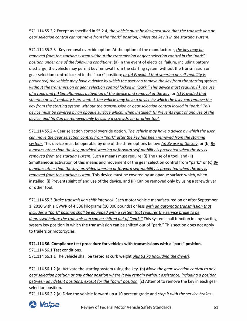
Review of Federal Motor Vehicle Safety Standards 61
571.114 S5.2.2 Except as specified in S5.2.4, the vehicle must be designed such that the transmission or
gear selection control cannot move from the “park” position, unless the key is in the starting system.
571.114 S5.2.3 Key removal override option. At the option of the manufacturer, the key may be
removed from the starting system without the transmission or gear selection control in the “park”
position under one of the following conditions: (a) In the event of electrical failure, including battery
discharge, the vehicle may permit key removal from the starting system without the transmission or
gear selection control locked in the “park” position; or (b) Provided that steering or self-mobility is
prevented, the vehicle may have a device by which the user can remove the key from the starting system
without the transmission or gear selection control locked in “park.” This device must require: (i) The use
of a tool, and (ii) Simultaneous activation of the device and removal of the key; or (c) Provided that
steering or self-mobility is prevented, the vehicle may have a device by which the user can remove the
key from the starting system without the transmission or gear selection control locked in “park.” This
device must be covered by an opaque surface which, when installed: (i) Prevents sight of and use of the
device, and (ii) Can be removed only by using a screwdriver or other tool.
571.114 S5.2.4 Gear selection control override option. The vehicle may have a device by which the user
can move the gear selection control from “park” after the key has been removed from the starting
system. This device must be operable by one of the three options below: (a) By use of the key; or (b) By
a means other than the key, provided steering or forward self-mobility is prevented when the key is
removed from the starting system. Such a means must require: (i) The use of a tool, and (ii)
Simultaneous activation of this means and movement of the gear selection control from “park;” or (c) By
a means other than the key, provided steering or forward self-mobility is prevented when the key is
removed from the starting system. This device must be covered by an opaque surface which, when
installed: (i) Prevents sight of and use of the device, and (ii) Can be removed only by using a screwdriver
or other tool.
571.114 S5.3 Brake transmission shift interlock. Each motor vehicle manufactured on or after September
1, 2010 with a GVWR of 4,536 kilograms (10,000 pounds) or less with an automatic transmission that
includes a “park” position shall be equipped with a system that requires the service brake to be
depressed before the transmission can be shifted out of “park.” This system shall function in any starting
system key position in which the transmission can be shifted out of “park.” This section does not apply
to trailers or motorcycles.
571.114 S6. Compliance test procedure for vehicles with transmissions with a “park” position.
571.114 S6.1 Test conditions.
571.114 S6.1.1 The vehicle shall be tested at curb weight plus 91 kg (including the driver).
571.114 S6.1.2 (a) Activate the starting system using the key. (b) Move the gear selection control to any
gear selection position or any other position where it will remain without assistance, including a position
between any detent positions, except for the “park” position. (c) Attempt to remove the key in each gear
selection position.
571.114 S6.2.2 (a) Drive the vehicle forward up a 10 percent grade and stop it with the service brakes.
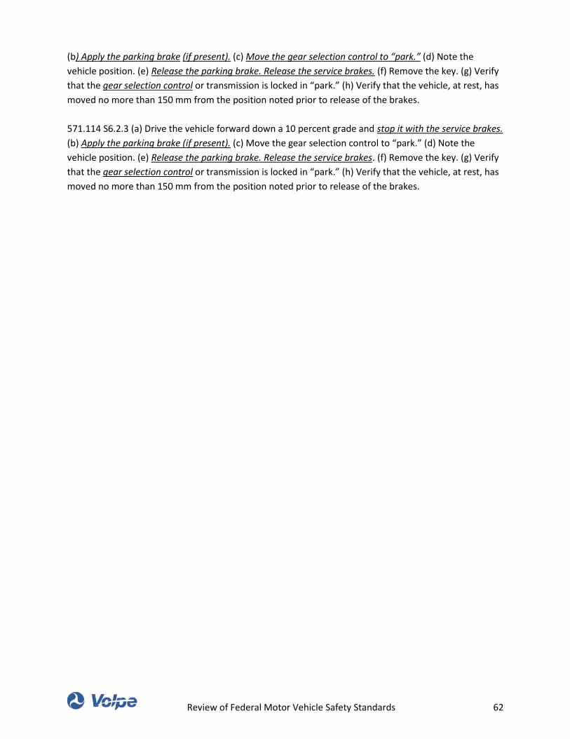
Review of Federal Motor Vehicle Safety Standards 62
(b) Apply the parking brake (if present). (c) Move the gear selection control to “park.” (d) Note the
vehicle position. (e) Release the parking brake. Release the service brakes. (f) Remove the key. (g) Verify
that the gear selection control or transmission is locked in “park.” (h) Verify that the vehicle, at rest, has
moved no more than 150 mm from the position noted prior to release of the brakes.
571.114 S6.2.3 (a) Drive the vehicle forward down a 10 percent grade and stop it with the service brakes.
(b) Apply the parking brake (if present). (c) Move the gear selection control to “park.” (d) Note the
vehicle position. (e) Release the parking brake. Release the service brakes. (f) Remove the key. (g) Verify
that the gear selection control or transmission is locked in “park.” (h) Verify that the vehicle, at rest, has
moved no more than 150 mm from the position noted prior to release of the brakes.
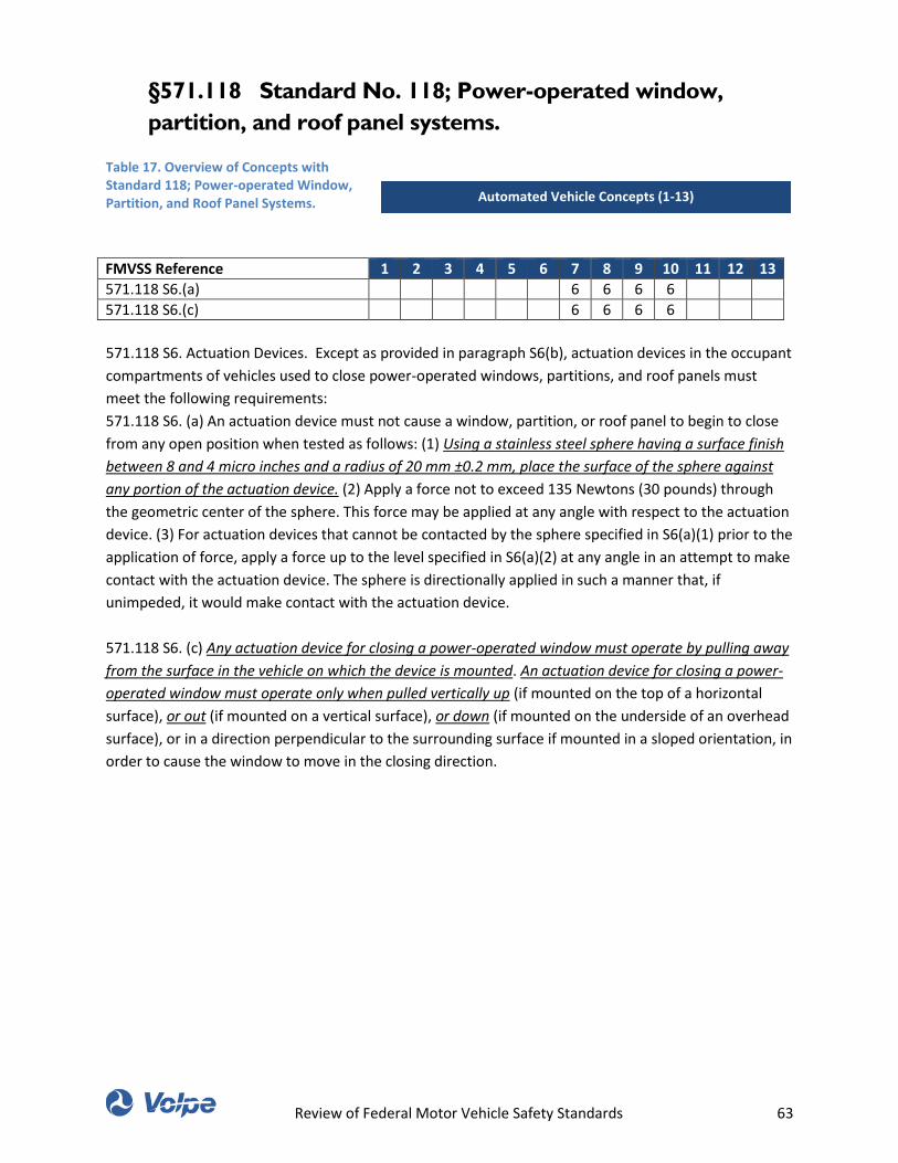
Review of Federal Motor Vehicle Safety Standards 63
§571.118 Standard No. 118; Power-operated window,
partition, and roof panel systems.
Table 17. Overview of Concepts with Standard 118; Power-operated Window, Partition, and Roof Panel Systems.
FMVSS Reference 1 2 3 4 5 6 7 8 9 10 11 12 13
571.118 S6.(a) 6 6 6 6
571.118 S6.(c) 6 6 6 6
571.118 S6. Actuation Devices. Except as provided in paragraph S6(b), actuation devices in the occupant
compartments of vehicles used to close power-operated windows, partitions, and roof panels must
meet the following requirements:
571.118 S6. (a) An actuation device must not cause a window, partition, or roof panel to begin to close
from any open position when tested as follows: (1) Using a stainless steel sphere having a surface finish
between 8 and 4 micro inches and a radius of 20 mm ±0.2 mm, place the surface of the sphere against
any portion of the actuation device. (2) Apply a force not to exceed 135 Newtons (30 pounds) through
the geometric center of the sphere. This force may be applied at any angle with respect to the actuation
device. (3) For actuation devices that cannot be contacted by the sphere specified in S6(a)(1) prior to the
application of force, apply a force up to the level specified in S6(a)(2) at any angle in an attempt to make
contact with the actuation device. The sphere is directionally applied in such a manner that, if
unimpeded, it would make contact with the actuation device.
571.118 S6. (c) Any actuation device for closing a power-operated window must operate by pulling away
from the surface in the vehicle on which the device is mounted. An actuation device for closing a power-
operated window must operate only when pulled vertically up (if mounted on the top of a horizontal
surface), or out (if mounted on a vertical surface), or down (if mounted on the underside of an overhead
surface), or in a direction perpendicular to the surrounding surface if mounted in a sloped orientation, in
order to cause the window to move in the closing direction.
Automated Vehicle Concepts (1-13)
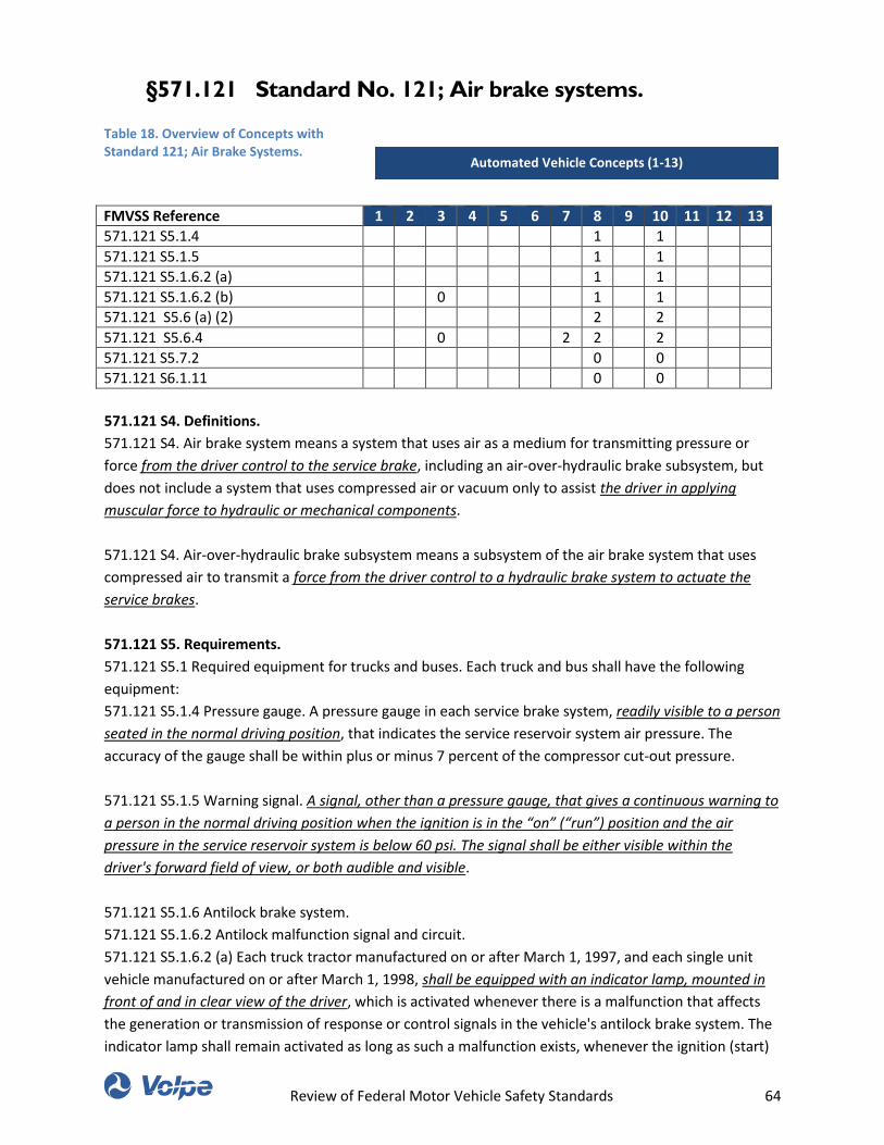
Review of Federal Motor Vehicle Safety Standards 64
§571.121 Standard No. 121; Air brake systems.
Table 18. Overview of Concepts with Standard 121; Air Brake Systems.
FMVSS Reference 1 2 3 4 5 6 7 8 9 10 11 12 13
571.121 S5.1.4 1 1
571.121 S5.1.5 1 1
571.121 S5.1.6.2 (a) 1 1
571.121 S5.1.6.2 (b) 0 1 1
571.121 S5.6 (a) (2) 2 2
571.121 S5.6.4 0 2 2 2
571.121 S5.7.2 0 0
571.121 S6.1.11 0 0
571.121 S4. Definitions.
571.121 S4. Air brake system means a system that uses air as a medium for transmitting pressure or
force from the driver control to the service brake, including an air-over-hydraulic brake subsystem, but
does not include a system that uses compressed air or vacuum only to assist the driver in applying
muscular force to hydraulic or mechanical components.
571.121 S4. Air-over-hydraulic brake subsystem means a subsystem of the air brake system that uses
compressed air to transmit a force from the driver control to a hydraulic brake system to actuate the
service brakes.
571.121 S5. Requirements.
571.121 S5.1 Required equipment for trucks and buses. Each truck and bus shall have the following
equipment:
571.121 S5.1.4 Pressure gauge. A pressure gauge in each service brake system, readily visible to a person
seated in the normal driving position, that indicates the service reservoir system air pressure. The
accuracy of the gauge shall be within plus or minus 7 percent of the compressor cut-out pressure.
571.121 S5.1.5 Warning signal. A signal, other than a pressure gauge, that gives a continuous warning to
a person in the normal driving position when the ignition is in the “on” (“run”) position and the air
pressure in the service reservoir system is below 60 psi. The signal shall be either visible within the
driver's forward field of view, or both audible and visible.
571.121 S5.1.6 Antilock brake system.
571.121 S5.1.6.2 Antilock malfunction signal and circuit.
571.121 S5.1.6.2 (a) Each truck tractor manufactured on or after March 1, 1997, and each single unit
vehicle manufactured on or after March 1, 1998, shall be equipped with an indicator lamp, mounted in
front of and in clear view of the driver, which is activated whenever there is a malfunction that affects
the generation or transmission of response or control signals in the vehicle's antilock brake system. The
indicator lamp shall remain activated as long as such a malfunction exists, whenever the ignition (start)
Automated Vehicle Concepts (1-13)
Review of Federal Motor Vehicle Safety Standards 65
switch is in the “on” (“run”) position, whether or not the engine is running. Each message about the
existence of such a malfunction shall be stored in the antilock brake system after the ignition switch is
turned to the “off” position and automatically reactivated when the ignition switch is again turned to
the “on” (“run”) position. The indicator lamp shall also be activated as a check of lamp function
whenever the ignition is turned to the “on” (“run”) position. The indicator lamp shall be deactivated at
the end of the check of lamp function unless there is a malfunction or a message about a malfunction
that existed when the key switch was last turned to the “off” position.
571.121 S5.1.6.2 (b) Each truck tractor manufactured on or after March 1, 2001, and each single unit
vehicle manufactured on or after March 1, 2001, that is equipped to tow another air-braked vehicle,
shall be equipped with an electrical circuit that is capable of transmitting a malfunction signal from the
antilock brake system(s) on one or more towed vehicle(s) (e.g., trailer(s) and dolly(ies)) to the trailer ABS
malfunction lamp in the cab of the towing vehicle, and shall have the means for connection of this
electrical circuit to the towed vehicle. Each such truck tractor and single unit vehicle shall also be
equipped with an indicator lamp, separate from the lamp required in S5.1.6.2(a), mounted in front of and
in clear view of the driver, which is activated whenever the malfunction signal circuit described above
receives a signal indicating an ABS malfunction on one or more towed vehicle(s). The indicator lamp shall
remain activated as long as an ABS malfunction signal from one or more towed vehicle(s) is present,
whenever the ignition (start) switch is in the “on” (“run”) position, whether or not the engine is running.
The indicator lamp shall also be activated as a check of lamp function whenever the ignition is turned to
the “on” (“run”) position. The indicator lamp shall be deactivated at the end of the check of lamp
function unless a trailer ABS malfunction signal is present.
571.121 S5.3 Service brakes
571.121 S5.3.1 Stopping distance – trucks and buses.
571.121 S5.3.1.1 Stop the vehicle from 60 mph on a surface with a peak friction coefficient of 0.9 with
the vehicle loaded as follows: (a) Loaded to its GVWR so that the load on each axle, measured at the
tire-ground interface, is most nearly proportional to the axles' respective GAWRs, without exceeding the
GAWR of any axle. (b) In the truck tractor only configuration plus up to 500 lbs. or, at the manufacturer's
option, at its unloaded weight plus up to 500 lbs. (including driver and instrumentation) and plus not
more than an additional 1,000 lbs. for a roll bar structure on the vehicle, and (c) At its unloaded vehicle
weight (except for truck tractors) plus up to 500 lbs. (including driver and instrumentation) or, at the
manufacturer's option, at its unloaded weight plus up to 500 lbs. (including driver and instrumentation)
plus not more than an additional 1,000 lbs. for a roll bar structure on the vehicle. If the speed attainable
in two miles is less than 60 mph, the vehicle shall stop from a speed in Table II that is four to eight mph
less than the speed attainable in two miles.
571.121 S5.3.6 Stability and control during braking – trucks and buses.
571.121 S5.3.6.2 Stop the vehicle, with the vehicle: (a) Loaded to its GVWR, for a truck tractor, and (b)
At its unloaded weight plus up to 500 pounds (including driver and instrumentation), or at the
manufacturer's option, at its unloaded weight plus up to 500 pounds (including driver and
instrumentation) and plus not more than an additional 1000 pounds for a roll bar structure on the
vehicle, for a truck, bus, or truck tractor.
571.121 S5.6 Parking brakes.
Review of Federal Motor Vehicle Safety Standards 66
571.121 S5.6.1 (a) Except as provided in S5.6(b) and S5.6(c), each vehicle other than a trailer converter
dolly shall have a parking brake system that under the conditions of S6.1 meets the requirements of: (1)
S5.6.1 or S5.6.2, at the manufacturer's option, and (2) S5.6.3, S5.6.4, S5.6.5, and S5.6.6.
571.121 S5.6.4 Parking brake control—trucks and buses. The parking brake control shall be separate
from the service brake control. It shall be operable by a person seated in the normal driving position. The
control shall be identified in a manner that specifies the method of control operation. The parking brake
control shall control the parking brakes of the vehicle and of any air braked vehicle that it is designed to
tow.
571.121 S5.7 Emergency brake system for trucks and buses.
571.121 S5.7.2 Emergency brake system operation. The emergency brake system shall be applied and
released, and be capable of modulation, by means of the service brake control.
571.121 S6. Conditions.
571.121 S6.1 Road test conditions.
571.121 S6.1.11 Special drive conditions. A vehicle equipped with an interlocking axle system or a front
wheel drive system that is engaged and disengaged by the driver is tested with the system disengaged.

Review of Federal Motor Vehicle Safety Standards 67
§571.122 Standard No. 122; Motorcycle brake systems.
Table 19. Overview of Concepts with Standard 122; Motorcycle Brake Systems.
FMVSS Reference 1 2 3 4 5 6 7 8 9 10 11 12 13
571.122 S5.1.1 2 0
571.122 S5.1.2 2 0
571.122 S5.1.3 2 0
571.122 S5.1.4 2 0
571.122 S5.1.5 2 0
571.122 S5.1.6 2 0
571.122 S5.1.7 2 0
571.122 S5.1.10 1 0
571.122 S5.1.10.1 1 0
571.122 S5.1.10.2 1 0
571.122 S5.3.2 4 0
571.122 S6.2.3 2 0
571.122 S6.3.3 2 0
571.122 S6.2.5.2 2 0
571.122 S6.3.2 2 0
571.122 S6.4.2 2 0
571.122 S6.4.3 2 0
571.122 S6.5.2 2 0
571.122 S6.5.3 2 0
571.122 S6.6.1 2 0
571.122 S6.6.3 2 0
571.122 S6.6.4 2 0
571.122 S6.6.5 2 0
571.122 S6.7.1 2 0
571.122 S6.7.2.2 5 0
571.122 S6.7.4 2 0
571.122 S6.8.2 5 0
571.122 S6.8.3 5 0
571.122 S6.9.3.1 2 0
571.122 S6.9.4.1 2 0
571.122 S6.9.4.2 0 0
571.122 S6.9.5.1 5 0
571.122 S6.9.5.2 2 0
571.122 S6.9.6.1 2 0
571.122 S6.9.6.2 2 0
571.122 S6.9.7.1 2 0
571.122 S6.9.7.2 2 0
571.122 S6.9.8.1 2 0
571.122 S6.9.8.2 2 0
571.122 S6.10.3 5 0
571.122 S6.11.2 2 0
Automated Vehicle Concepts (1-13)
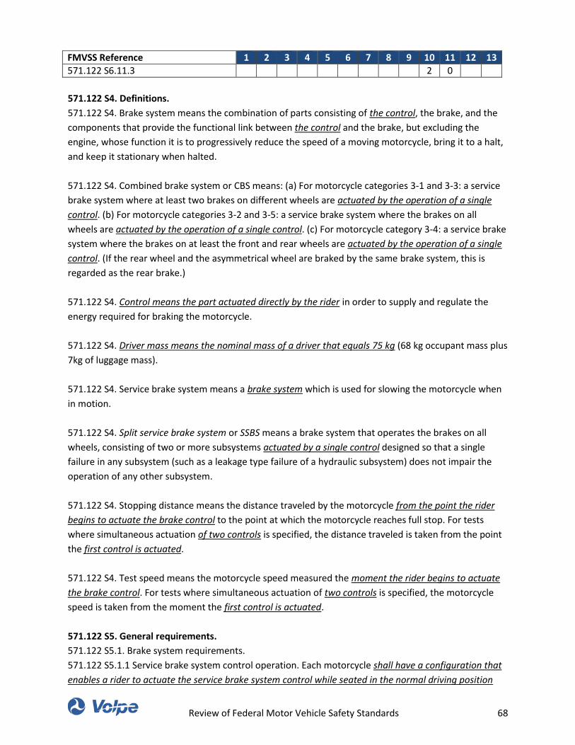
Review of Federal Motor Vehicle Safety Standards 68
FMVSS Reference 1 2 3 4 5 6 7 8 9 10 11 12 13
571.122 S6.11.3 2 0
571.122 S4. Definitions.
571.122 S4. Brake system means the combination of parts consisting of the control, the brake, and the
components that provide the functional link between the control and the brake, but excluding the
engine, whose function it is to progressively reduce the speed of a moving motorcycle, bring it to a halt,
and keep it stationary when halted.
571.122 S4. Combined brake system or CBS means: (a) For motorcycle categories 3-1 and 3-3: a service
brake system where at least two brakes on different wheels are actuated by the operation of a single
control. (b) For motorcycle categories 3-2 and 3-5: a service brake system where the brakes on all
wheels are actuated by the operation of a single control. (c) For motorcycle category 3-4: a service brake
system where the brakes on at least the front and rear wheels are actuated by the operation of a single
control. (If the rear wheel and the asymmetrical wheel are braked by the same brake system, this is
regarded as the rear brake.)
571.122 S4. Control means the part actuated directly by the rider in order to supply and regulate the
energy required for braking the motorcycle.
571.122 S4. Driver mass means the nominal mass of a driver that equals 75 kg (68 kg occupant mass plus
7kg of luggage mass).
571.122 S4. Service brake system means a brake system which is used for slowing the motorcycle when
in motion.
571.122 S4. Split service brake system or SSBS means a brake system that operates the brakes on all
wheels, consisting of two or more subsystems actuated by a single control designed so that a single
failure in any subsystem (such as a leakage type failure of a hydraulic subsystem) does not impair the
operation of any other subsystem.
571.122 S4. Stopping distance means the distance traveled by the motorcycle from the point the rider
begins to actuate the brake control to the point at which the motorcycle reaches full stop. For tests
where simultaneous actuation of two controls is specified, the distance traveled is taken from the point
the first control is actuated.
571.122 S4. Test speed means the motorcycle speed measured the moment the rider begins to actuate
the brake control. For tests where simultaneous actuation of two controls is specified, the motorcycle
speed is taken from the moment the first control is actuated.
571.122 S5. General requirements.
571.122 S5.1. Brake system requirements.
571.122 S5.1.1 Service brake system control operation. Each motorcycle shall have a configuration that
enables a rider to actuate the service brake system control while seated in the normal driving position
Review of Federal Motor Vehicle Safety Standards 69
and with both hands on the steering control.
571.122 S5.1.2 Secondary brake system control operation. Each motorcycle shall have a configuration
that enables a rider to actuate the secondary brake system control while seated in the normal driving
position and with at least one hand on the steering control.
571.122 S5.1.3 Parking brake system. (a) If a parking brake system is fitted, it shall hold the motorcycle
stationary on the slope prescribed in S6.8.2. The parking brake system shall: (1) have a control which is
separate from the service brake system controls; and (2) be held in the locked position by solely
mechanical means. (b) Each motorcycle equipped with a parking brake shall have a configuration that
enables a rider to be able to actuate the parking brake system while seated in the normal driving
position.
571.122 S5.1.4 Two-wheeled motorcycles of categories 3-1 and 3-3. Each category 3-1 and 3-3 two-
wheeled motorcycle shall be equipped with either two separate service brake systems, or a split service
brake system, with at least one brake operating on the front wheel and at least one brake operating on
the rear wheel.
571.122 S5.1.5 Three-wheeled motorcycles of category 3-4. Each category 3-4 motorcycle shall comply
with the brake system requirements in S5.1.4. A brake on the asymmetric wheel (with respect to the
longitudinal axis) is not required.
571.122 S5.1.6 Three-wheeled motorcycles of category 3-2. Each category 3-2 motorcycle shall be
equipped with a parking brake system plus one of the following service brake systems: (a) Two separate
service brake systems, except CBS, which, when applied together, operate the brakes on all wheels; or
(b) A split service brake system; or (c) A CBS that operates the brake on all wheels and a secondary brake
system which may be the parking brake system.
571.122 S5.1.7 Three-wheeled motorcycles of categories 3-5. Each category 3-5 motorcycle shall be
equipped with: (a) A parking brake system; and (b) A foot actuated service brake system which operates
the brakes on all wheels by way of either: (1) A split service brake system; or (2) A CBS and a secondary
brake system, which may be the parking brake system.
571.122 S5.1.10 Warning lamps. All warning lamps shall be mounted in the rider's view.
571.122 S5.1.10.1 Split service brake system warning lamps.
571.122 S5.1.10.1 (a) Each motorcycle that is equipped with a split service brake system shall be fitted
with a red warning lamp, which shall be activated: (1) When there is a hydraulic failure on the
application of a force of ≤90 N on the control; or (2) Without actuation of the brake control, when the
brake fluid level in the master cylinder reservoir falls below the greater of: (i) That which is specified by
the manufacturer; or (ii) That which is less than or equal to half of the fluid reservoir capacity.
571.122 S5.1.10.1 (b) To permit function checking, the warning lamp shall be illuminated by the
activation of the ignition switch and shall be extinguished when the check has been completed. The
warning lamp shall remain on while a failure condition exists whenever the ignition switch is in the “on”
Review of Federal Motor Vehicle Safety Standards 70
position.
571.122 S5.1.10.1 (c) Each indicator lamp shall have the legend “Brake Failure” on or adjacent to it in
letters not less than 3/32 of an inch high that shall be legible to the driver in daylight when lighted.
571.122 S5.1.10.2 Antilock brake system warning lamps.
571.122 S5.1.10.2 (a) Each motorcycle equipped with an ABS system shall be fitted with a yellow
warning lamp. The lamp shall be activated whenever there is a malfunction that affects the generation
or transmission of signals in the motorcycle's ABS system.
571.122 S5.1.10.2 (b) To permit function checking, the warning lamp shall be illuminated by the
activation of the ignition switch and extinguished when the check has been completed. The warning lamp
shall remain on while a failure condition exists whenever the ignition switch is in the “on” position.
571.122 S5.1.10.2 (c) The indicator shall be labeled in letters at least 3/32 of an inch high with the words
“Antilock” or “Anti-lock” or “ABS” in accordance with Table 1 of Standard No. 101 (49 CFR 571.101).
571.122 S5.3 Measurement of dynamic performance.
571.122 S5.3.2 Continuous deceleration recording. The other method used to measure performance is
the continuous recording of the vehicle instantaneous deceleration from the moment a force is applied
to the brake control until the end of the stop.
571.122 S6. Test conditions, procedures and performance requirements.
571.122 S6.2. Preparation.
571.122 S6.2.3. Control application points and direction. For a hand control lever, the input force (F) is
applied on the control lever's forward surface perpendicular to the axis of the lever fulcrum and its
outermost point on the plane along which the control lever rotates (see Figure 1). The input force is
applied to a point located 50 millimeters (mm) from the outermost point of the control lever, measured
along the axis between the central axis of the fulcrum of the lever and its outermost point. For a foot
control pedal, the input force is applied to the center of, and at right angles to, the control pedal.
571.122 S6.2.5. Burnishing procedure.
571.122 S6.2.5.2. Conditions and procedure. (a) Initial brake temperature. Initial brake temperature
before each brake application is ≤100 °C. (b) Test speed. (1) Initial speed: 50 km/h or 0.8 Vmax,
whichever is lower. (2) Final speed = 5 to 10 km/h. (c) Brake application. Each service brake system
control actuated separately. (d) Vehicle deceleration. (1) Single front brake system only: (i) 3.0-3.5
meters per second squared (m/s2) for motorcycle categories 3-3 and 3-4 (ii) 1.5-2.0 m/s2 for motorcycle
categories 3-1 and 3-2 (2) Single rear brake system only: 1.5-2.0 m/s2 (3) CBS or split service brake
system, and category 3-5: 3.5-4.0 m/s2 (e) Number of decelerations. There shall be 100 decelerations
per brake system. (f) For the first stop, accelerate the vehicle to the initial speed and then actuate the
brake control under the conditions specified until the final speed is reached. Then reaccelerate to the
initial speed and maintain that speed until the brake temperature falls to the specified initial value.
When these conditions are met, reapply the brake as specified. Repeat this procedure for the number of
specified decelerations. After burnishing, adjust the brakes in accordance with the manufacturer's
Review of Federal Motor Vehicle Safety Standards 71
recommendations.
571.122 S6.3. Dry stop test – single brake control actuated.
571.122 S6.3.2. Test conditions and procedure. (a) Initial brake temperature. Initial brake temperature is
≥55 °C and ≤100 °C. (b) Test speed. (1) Motorcycle categories 3-1 and 3-2: 40 km/h or 0.9 Vmax,
whichever is lower. (2) Motorcycle categories 3-3, 3-4 and 3-5: 60 km/h or 0.9 Vmax, whichever is lower.
(c) Brake application. Each service brake system control actuated separately. (d) Brake actuation force.
(1) Hand control: ≤200 N. (2) Foot control: (i) ≤350 N for motorcycle categories 3-1, 3-2, 3-3 and 3-5. (ii)
≤500 N for motorcycle category 3-4. (e) Number of stops: until the vehicle meets the performance
requirements, with a maximum of 6 stops. (f) For each stop, accelerate the vehicle to the test speed and
then actuate the brake control under the conditions specified in this paragraph.
571.122 S6.3.3. Performance requirements. When the brakes are tested in accordance with the test
procedure set out in paragraph S6.3.2., the stopping distance shall be as specified in column 2 of Table
2.
571.122 S6.4. Dry stop test – all service brake controls actuated.
571.122 S6.4.2. Test conditions and procedure. (a) Initial brake temperature. Initial brake temperature is
≥55 °C and ≤100 °C. (b) Test speed. Test speed is 100 km/h or 0.9 Vmax, whichever is lower. (c) Brake
application. Simultaneous actuation of both service brake system controls, if so equipped, or of the single
service brake system control in the case of a service brake system that operates on all wheels. (d) Brake
actuation force. (1) Hand control: ≤250 N. (2) Foot control: (i) ≤400 N for motorcycle categories 3-3 and
3-4. (ii) ≤500 N for motorcycle category 3-5. (e) Number of stops: until the vehicle meets the
performance requirements, with a maximum of 6 stops. (f) For each stop, accelerate the vehicle to the
test speed and then actuate the brake control under the conditions specified in this paragraph.
571.122 S6.4.3. Performance requirements. When the brakes are tested in accordance with the test
procedure set out in paragraph S6.4.2., the stopping distance (S) shall be S ≤0.0060 V2 (where V is the
specified test speed in km/h and S is the required stopping distance in meters).
571.122 S6.5. High speed test.
571.122 S6.5.2. Test conditions and procedure. (a) Initial brake temperature. Initial brake temperature
is ≥55 °C and ≤100 °C. (b) Test speed. (1) Test speed is 0.8 Vmax for motorcycles with Vmax >125 km/h
and <200 km/h. (2) Test speed is 160 km/h for motorcycles with Vmax ≥200 km/h. (c) Brake application.
Simultaneous actuation of both service brake system controls, if so equipped, or of the single service
brake system control in the case of a service brake system that operates on all wheels. (d) Brake
actuation force. (1) Hand control: ≤200 N. (2) Foot control: (i) ≤350 N for motorcycle categories 3-3 and
3-4. (ii) ≤500 N for motorcycle category 3-5. (e) Number of stops: until the vehicle meets the
performance requirements, with a maximum of 6 stops. (f) For each stop, accelerate the vehicle to the
test speed and then actuate the brake control(s) under the conditions specified in this paragraph.
571.122 S6.5.3 Performance requirements. When the brakes are tested in accordance with the test
procedure set out in paragraph S6.5.2, the stopping distance (S) shall be ≤0.1 V + 0.0067 V2 (where V is
the specified test speed in km/h and S is the required stopping distance in meters).
Review of Federal Motor Vehicle Safety Standards 72
571.122 S6.6. Wet brake test.
571.122 S6.6.1. General information. (a) The test is comprised of two parts that are carried out
consecutively for each brake system: (1) A baseline test based on the dry stop test—single brake control
actuated (S6.3). (2) A single wet brake stop using the same test parameters as in (1), but with the
brake(s) being continuously sprayed with water while the test is conducted in order to measure the
brakes' performance in wet conditions.
571.122 S6.6.3. Baseline test – test conditions and procedure. (a) The test in paragraph S6.3 (dry stop
test—single brake control actuated) is carried out for each brake system but with the brake control force
that results in a vehicle deceleration of 2.5-3.0 m/s2, and the following is determined: (1) The average
brake control force measured when the vehicle is traveling between 80 percent and 10 percent of the
specified test speed. (2) The average vehicle deceleration in the period 0.5 to 1.0 seconds after the point
of actuation of the brake control. (3) The maximum vehicle deceleration during the complete stop but
excluding the final 0.5 seconds. (b) Conduct 3 baseline stops and average the values obtained in (1), (2),
and (3).
571.122 S6.6.4. Wet brake test – test conditions and procedure. (a) The vehicle is ridden at the test
speed used in the baseline test set out in S6.6.3 with the water spray equipment operating on the
brake(s) to be tested and with no application of the brake system. (b) After a distance of ≥500 m, apply
the average brake control force determined in the baseline test for the brake system being tested. (c)
Measure the average vehicle deceleration in the period 0.5 to 1.0 seconds after the point of actuation of
the brake control. (d) Measure the maximum vehicle deceleration during the complete stop but
excluding the final 0.5 seconds.
571.122 S6.6.5. Performance requirements. When the brakes are tested in accordance with the test
procedure set out in paragraph S6.6.4, the wet brake deceleration performance shall be: (a) The value
measured in paragraph S6.6.4(c) shall be ≥60 percent of the average deceleration values recorded in the
baseline test in paragraph S6.6.3(a)(2), i.e., in the period 0.5 to 1.0 seconds after the point of actuation
of the brake control; and (b) The value measured in S6.6.4(d) shall be ≤120 percent of the average
deceleration values recorded in the baseline test S6.6.3(a)(3), i.e., during the complete stop but
excluding the final 0.5 seconds.
571.122 S6.7 Heat fade test.
571.122 S6.7.1. General information. (a) The test comprises three parts that are carried out
consecutively for each brake system: (1) A baseline test using the dry stop test—single brake control
actuated (S6.3). (2) A heating procedure which consists of a series of repeated stops in order to heat the
brake(s). (3) A hot brake stop using the dry stop test—single brake control actuated (S6.3), to measure
the brake's performance after the heating procedure. (b) The test is applicable to motorcycle categories
3-3, 3-4 and 3-5. (c) The test is not applicable to parking brake systems and secondary service brake
systems. (d) All stops are carried out with the motorcycle laden. (e) The heating procedure requires the
motorcycle to be fitted with instrumentation that gives a continuous recording of brake control force
and vehicle deceleration.
571.122 S6.7.2. Baseline test.
Review of Federal Motor Vehicle Safety Standards 73
571.122 S6.7.2.2. Test conditions and procedure – baseline test. (a) Initial brake temperature. Initial
brake temperature is ≥55 °C and ≤100 °C. (b) Test speed. Test speed is 60 km/h or 0.9 Vmax, whichever
is the lower. (c) Brake application. Each service brake system control is actuated separately. (d) Brake
actuation force. (1) Hand control: ≤200 N. (2) Foot control: (i) ≤350 N for motorcycle categories 3-3 and
3-4. (ii) ≤500 N for motorcycle category 3-5. (e) Accelerate the vehicle to the test speed, actuate the
brake control under the conditions specified and record the control force required to achieve the vehicle
braking performance specified in the table to S6.3.3 (Table 2).
571.122 S6.7.4 Hot brake stop—test conditions and procedure. Perform a single stop under the
conditions used in the baseline test (S6.7.2) for the brake system that has been heated during the
procedure in accordance with S6.7.3. This stop is carried out within one minute of the completion of the
procedure set out in S6.7.3 with a brake control application force less than or equal to the force used
during the test set out in S6.7.2.
571.122 S6.8 Parking brake system test – for motorcycles with parking brakes.
571.122 S6.8.2 Test conditions and procedure. (a) Initial brake temperature. Initial brake temperature is
≤100 °C. (b) Test surface gradient. Test surface gradient is equal to 18 percent. (c) Brake actuation force.
(1) Hand control: ≤400 N. (2) Foot control: ≤500 N. (d) For the first part of the test, park the vehicle on
the test surface gradient facing up the slope by applying the parking brake system under the conditions
specified in this paragraph. If the vehicle remains stationary, start the measurement of the test period.
(e) The vehicle must remain stationary to the limits of traction of the braked wheels. (f) On completion
of the test with vehicle facing up the gradient, repeat the same test procedure with the vehicle facing
down the gradient.
571.122 S6.8.3 Performance requirements. When tested in accordance with the test procedure set out in
S6.8.2, the parking brake system shall hold the vehicle stationary for 5 minutes when the vehicle is both
facing up and facing down the gradient.
571.122 S6.9 ABS tests.
571.122 S6.9.3 Stops on a high friction surface.
571.122 S6.9.3.1 Test conditions and procedure. (a) Initial brake temperature. Initial brake temperature
is ≥55 °C and ≤100 °C. (b) Test speed. Test speed is 60 km/h or 0.9 Vmax, whichever is lower. (c) Brake
application. Simultaneous actuation of both service brake system controls, if so equipped, or of the
single service brake control in the case of a service brake system that operates on all wheels. (d) Brake
actuation force. The force applied is that which is necessary to ensure that the ABS will cycle fully
throughout each stop, down to 10 km/h. (e) If one wheel is not equipped with ABS, the control for the
service brake on that wheel is actuated with a force that is lower than the force that will cause the wheel
to lock. (f) Number of stops: until the vehicle meets the performance requirements, with a maximum of
6 stops. (g) For each stop, accelerate the vehicle to the test speed and then actuate the brake control
under the conditions specified in this paragraph.
571.122 S6.9.4 Stops on a low friction surface.
571.122 S6.9.4.1 Test conditions and procedure. As set out in S6.9.3.1, but using the low friction
surface instead of the high friction one.
Review of Federal Motor Vehicle Safety Standards 74
571.122 S6.9.4.2 Performance requirements. When the brakes are tested in accordance with the test
procedures set out in S6.9.4.1: (a) the stopping distance (S) shall be ≤0.0056 V2/P (where V is the
specified test speed in km/h, P is the peak braking coefficient and S is the required stopping distance in
meters); and (b) there shall be no wheel lock beyond that allowed for in paragraph S6.9.1(d), and the
vehicle wheels shall stay within the test lane.
571.122 S6.9.5 Wheel lock checks on high and low friction surfaces.
571.122 S6.9.5.1 Test conditions and procedure. (a) Test surfaces. High friction or low friction surface, as
applicable. (b) Initial brake temperature. Initial brake temperature is ≥55 °C and ≤100 °C. (c) Test speed.
(1) On the high friction surface: 80 km/h or 0.8 Vmax, whichever is lower. (2) On the low friction surface:
60 km/h or 0.8 Vmax, whichever is lower. (d) Brake application. (1) Each service brake system control
actuated separately. (2) Where ABS is fitted to both brake systems, simultaneous actuation of both
brake controls in addition to (1). (e) Brake actuation force. The force applied is that which is necessary to
ensure that the ABS will cycle fully throughout each stop, down to 10 km/h. (f) Brake application rate.
The brake control actuation force is applied in 0.2-0.5 seconds. (g) Number of stops: until the vehicle
meets the performance requirements, with a maximum of 3 stops. (h) For each stop, accelerate the
vehicle to the test speed and then actuate the brake control under the conditions specified in this
paragraph.
571.122 S6.9.5.2 Performance requirements. When the brakes are tested in accordance with the test
procedures set out in S6.9.5.1, there shall be no wheel lock beyond that allowed for in paragraph
S6.9.1(d), and the vehicle wheels shall stay within the test lane.
571.122 S6.9.6 Wheel lock check—high to low friction surface transition.
571.122 S6.9.6.1 Test conditions and procedure. (a) Test surfaces. A high friction surface immediately
followed by a low friction surface. (b) Initial brake temperature. Initial brake temperature is ≥55 °C and
≤100 °C. (c) Test speed. The speed that will result in 50 km/h or 0.5 Vmax, whichever is the lower, at the
point where the vehicle passes from the high friction to the low friction surface. (d) Brake application.
(1) Each service brake system control actuated separately. (2) Where ABS is fitted to both brake systems,
simultaneous actuation of both brake controls in addition to (1). (e) Brake actuation force. The force
applied is that which is necessary to ensure that the ABS will cycle fully throughout each stop, down to
10 km/h. (f) Number of stops: until the vehicle meets the performance requirements, with a maximum
of 3 stops. (g) For each stop, accelerate the vehicle to the test speed and then actuate the brake control
before the vehicle reaches the transition from one friction surface to the other.
571.122 S6.9.6.2 Performance requirements. When the brakes are tested in accordance with the test
procedures set out in S6.9.6.1, there shall be no wheel lock beyond that allowed for in paragraph
S6.9.1(d), and the vehicle wheels shall stay within the test lane.
571.122 S6.9.7 Wheel lock check – low to high friction surface transition.
571.122 S6.9.7.1 Test conditions and procedure. (a) Test surfaces. A low friction surface immediately
followed by a high friction surface with a PBC ≥0.8. (b) Initial brake temperature. Initial brake
temperature is ≥55 °C and ≤100 °C. (c) Test speed. The speed that will result in 50 km/h or 0.5 Vmax,
Review of Federal Motor Vehicle Safety Standards 75
whichever is the lower, at the point where the vehicle passes from the low friction to the high friction
surface. (d) Brake application. (1) Each service brake system control applied separately. (2) Where ABS is
fitted to both brake systems, simultaneous application of both brake controls in addition to (1). (e) Brake
actuation force. The force applied is that which is necessary to ensure that the ABS will cycle fully
throughout each stop, down to 10 km/h. (f) Number of stops: until the vehicle meets the performance
requirements, with a maximum of 3 stops. (g) For each stop, accelerate the vehicle to the test speed and
then actuate the brake control before the vehicle reaches the transition from one friction surface to the
other. (h) Record the vehicle's continuous deceleration.
571.122 S6.9.7.2 Performance requirements. When the brakes are tested in accordance with the test
procedures set out in S6.9.7.1: (a) There shall be no wheel lock beyond that allowed for in paragraph
S6.9.1(d), and the vehicle wheels shall stay within the test lane, and (b) within 1 second of the rear
wheel passing the transition point between the low and high friction surfaces, the vehicle deceleration
shall increase.
571.122 S6.9.8 Stops with an ABS electrical failure.
571.122 S6.9.8.1 Test conditions and procedure. With the ABS electrical system disabled, carry out the
test set out in S6.3 (dry stop test—single brake control actuated) applying the conditions relevant to the
brake system and vehicle being tested.
571.122 S6.9.8.2 Performance requirements. When the brakes are tested in accordance with the test
procedure set out in S6.9.8.1: (a) The system shall comply with the failure warning requirements of
S5.1.10.2; and (b) the minimum requirements for stopping distance shall be as specified in column 2
under the heading “Single brake system, rear wheel(s) braking only” in Table 2.
571.122 S6.10 Partial failure test – for split service brake systems.
571.122 S6.10.3 Test conditions and procedure. (a) Initial brake temperature. Initial brake temperature
is ≥55 °C and ≤100 °C. (b) Test speed. Test speed is 50 km/h and 100 km/h or 0.8 Vmax, whichever is
lower. (c) Brake actuation force. (1) Hand control: ≤250 N. (2) Foot control: ≤400 N. (d) Number of stops:
until the vehicle meets the performance requirements, with a maximum of 6 stops for each test speed.
(e) Alter the service brake system to induce a complete loss of braking in any one subsystem. Then, for
each stop, accelerate the vehicle to the test speed and then actuate the brake control under the
conditions specified in this paragraph. (f) Repeat the test for each subsystem.
571.122 S6.11 Power-assisted braking system failure test.
571.122 S6.11.2 Test conditions and procedure. Carry out the test set out in S6.3.3 (dry stop test—single
brake control actuated) for each service brake system with the power assistance disabled.
571.122 S6.11.3 Performance requirements. When the brakes are tested in accordance with the test
procedure set out in S6.11.2, the stopping distance shall be as specified in column 2 of Table 4. Note
that if the power assistance may be activated by more than one control, the above performance shall be
achieved when each control is actuated separately.
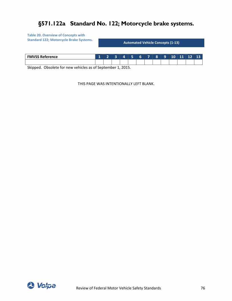
Review of Federal Motor Vehicle Safety Standards 76
§571.122a Standard No. 122; Motorcycle brake systems.
Table 20. Overview of Concepts with Standard 122; Motorcycle Brake Systems.
FMVSS Reference 1 2 3 4 5 6 7 8 9 10 11 12 13
Skipped. Obsolete for new vehicles as of September 1, 2015.
THIS PAGE WAS INTENTIONALLY LEFT BLANK.
Automated Vehicle Concepts (1-13)
Review of Federal Motor Vehicle Safety Standards 77
§571.123 Standard No. 123; Motorcycle controls and
displays.
Table 21. Overview of Concepts with Standard 123; Motorcycle Controls and Displays.
FMVSS Reference 1 2 3 4 5 6 7 8 9 10 11 12 13
This table was intentionally left blank. No automated vehicle concepts under consideration are
automated motorcycles with handlebars.
571.123 S3. Application.
This standard applies to motorcycles equipped with handlebars, except for motorcycles that are
designed, and sold exclusively for use by law enforcement agencies.
571.123 S4. Definitions.
571.123 S4. Clockwise and counterclockwise mean opposing directions of rotation around the following
axes, as applicable. (a) The operational axis of the ignition control, viewed from in front of the ignition
lock opening; (b) The axis of the right handlebar on which the twist-grip throttle is located, viewed from
the end of that handlebar; (c) The axis perpendicular to the center of the speedometer, viewed from the
operator's normal eye position.
571.123 S4. Scooter means a motorcycle that: (1) Has a platform for the operator's feet or has
integrated footrests, and (2) Has a step-through architecture, meaning that the part of the vehicle
forward of the operator's seat and between the legs of an operator seated in the riding position, is lower
in height than the operator's seat.
571.123 S5. Requirements.
571.123 S5.1. Each motorcycle shall be equipped with a supplemental engine stop control, located and
operable as specified in Table 1.
571.123 S5.2 Each motorcycle to which this standard applies shall meet the following requirements:
571.123 S5.2.1 Control location and operation. If any item of equipment listed in Table 1, Column 1, is
provided, the control for such item shall be located as specified in Column 2, and operable as specified in
Column 3. Each control located on a right handlebar shall be operable by the operator's right hand
throughout its full range without removal of the operator's right hand from the throttle. Each control
located on a left handlebar shall be operable by the operator's left hand throughout its full range
without removal of the operator's left hand from the handgrip. If a motorcycle with an automatic clutch
other than a scooter is equipped with a supplemental rear brake control, the control shall be located on
the left handlebar. If a scooter with an automatic clutch is equipped with a supplemental rear brake
control, the control shall be on the right side and operable by the operator's right foot. A supplemental
control shall provide brake actuation identical to that provided by the required control of Table 1, Item
Automated Vehicle Concepts (1-13)
Review of Federal Motor Vehicle Safety Standards 78
11, of this Standard. If a motorcycle is equipped with self-proportioning or antilock braking devices
utilizing a single control for front and rear brakes, the control shall be located and operable in the same
manner as a rear brake control, as specified in Table 1, Item 11, and in this paragraph.
571.123 S5.2.2 Display illumination and operation. If an item of equipment listed in Table 2, Column 1, is
provided, the display for such item shall be visible to a seated operator under daylight conditions, shall
illuminate as specified in Column 2, and shall operate as specified in Column 3.
571.123 S5.2.3 Control and display identification. If an item of equipment in Table 3, Column 1, is
provided, the item and its operational function shall be identified by: (a) A symbol substantially in the
form shown in Column 3; or (b) Wording shown in both Column 2 and Column 4; or (c) A symbol
substantially in the form shown in Column 3 and wording shown in both Column 2 and Column 4. (d) The
abbreviations “M.P.H.”, “km/h”, “r/min”, “Hi”, “Lo”, “L”, “R”, and “Res” appearing in Column 2 and
Column 4 may be spelled in full. Symbols and words may be provided for equipment items where none
are shown in Column 2, Column 3, and Column 4. Any identification provided shall be placed on or
adjacent to the control or display position, and shall appear upright to the operator.
Review of Federal Motor Vehicle Safety Standards 79
§571.124 Standard No. 124; Accelerator control systems.
Table 22. Overview of Concepts with Standard 124; Accelerator Control Systems.
FMVSS Reference 1 2 3 4 5 6 7 8 9 10 11 12 13
This table was intentionally left blank.
571.124 S1. Scope. This standard establishes requirements for the return of a vehicle's throttle to the
idle position when the driver removes the actuating force from the accelerator control, or in the event of
a severance or disconnection in the accelerator control system.
571.124 S4. Definitions.
571.124 S4.1. Driver-operated accelerator control system means all vehicle components, except the fuel
metering device, that regulate engine speed in direct response to movement of the driver-operated
control and that return the throttle to the idle position upon release of the actuating force.
571.124 S4.1. Throttle means the component of the fuel metering device that connects to the driver-
operated accelerator control system and that by input from the driver-operated accelerator control
system controls the engine speed.
571.124 S5. Requirements.
571.124 S5.1 There shall be at least two sources of energy capable of returning the throttle to the idle
position within the time limit specified by S5.3 from any accelerator position or speed whenever the
driver removes the opposing actuating force. In the event of failure of one source of energy by a single
severance or disconnection, the throttle shall return to the idle position within the time limits specified
by S5.3, from any accelerator position or speed whenever the driver removes the opposing actuating
force.
571.124 S5.2 The throttle shall return to the idle position from any accelerator position or any speed of
which the engine is capable whenever any one component of the accelerator control system is
disconnected or severed at a single point. The return to idle shall occur within the time limit specified by
S5.3, measured either from the time of severance or disconnection or from the first removal of the
opposing actuating force by the driver.
Automated Vehicle Concepts (1-13)
Review of Federal Motor Vehicle Safety Standards 80
§571.125 Standard No. 125; Warning devices.
Table 23. Overview of Concepts with Standard 125; Warning Devices.
FMVSS Reference 1 2 3 4 5 6 7 8 9 10 11 12 13
This table was intentionally left blank.
571.125 S5. Requirements.
571.125 S5.1.5 Each warning device shall have instructions for its erection and display. (a) The
instructions shall be either indelibly printed on the warning device or attached in such a manner that
they cannot be easily removed. (b) Instructions for each warning device shall include a recommendation
that the driver activate the vehicular hazard warning signal lamps before leaving the vehicle to erect the
warning device. (c) Instructions shall include the illustration depicted in Figure 3 indicating
recommended positioning.
Automated Vehicle Concepts (1-13)
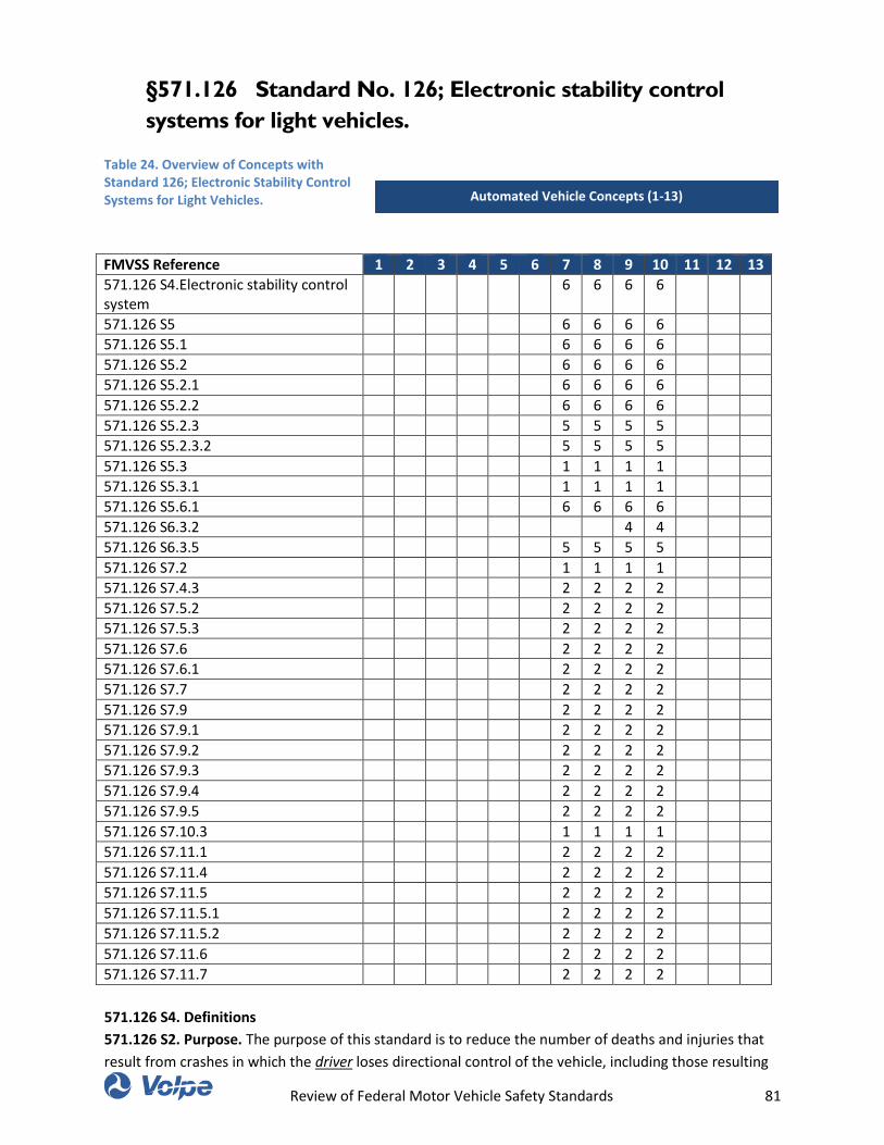
Review of Federal Motor Vehicle Safety Standards 81
§571.126 Standard No. 126; Electronic stability control
systems for light vehicles.
Table 24. Overview of Concepts with Standard 126; Electronic Stability Control Systems for Light Vehicles.
FMVSS Reference 1 2 3 4 5 6 7 8 9 10 11 12 13
571.126 S4.Electronic stability control system
6 6 6 6
571.126 S5 6 6 6 6
571.126 S5.1 6 6 6 6
571.126 S5.2 6 6 6 6
571.126 S5.2.1 6 6 6 6
571.126 S5.2.2 6 6 6 6
571.126 S5.2.3 5 5 5 5
571.126 S5.2.3.2 5 5 5 5
571.126 S5.3 1 1 1 1
571.126 S5.3.1 1 1 1 1
571.126 S5.6.1 6 6 6 6
571.126 S6.3.2 4 4
571.126 S6.3.5 5 5 5 5
571.126 S7.2 1 1 1 1
571.126 S7.4.3 2 2 2 2
571.126 S7.5.2 2 2 2 2
571.126 S7.5.3 2 2 2 2
571.126 S7.6 2 2 2 2
571.126 S7.6.1 2 2 2 2
571.126 S7.7 2 2 2 2
571.126 S7.9 2 2 2 2
571.126 S7.9.1 2 2 2 2
571.126 S7.9.2 2 2 2 2
571.126 S7.9.3 2 2 2 2
571.126 S7.9.4 2 2 2 2
571.126 S7.9.5 2 2 2 2
571.126 S7.10.3 1 1 1 1
571.126 S7.11.1 2 2 2 2
571.126 S7.11.4 2 2 2 2
571.126 S7.11.5 2 2 2 2
571.126 S7.11.5.1 2 2 2 2
571.126 S7.11.5.2 2 2 2 2
571.126 S7.11.6 2 2 2 2
571.126 S7.11.7 2 2 2 2
571.126 S4. Definitions
571.126 S2. Purpose. The purpose of this standard is to reduce the number of deaths and injuries that
result from crashes in which the driver loses directional control of the vehicle, including those resulting
Automated Vehicle Concepts (1-13)
Review of Federal Motor Vehicle Safety Standards 82
in vehicle rollover.
571.126 S4. Drive configuration means the driver-selected, or default, condition for distributing power
from the engine to the drive wheels (examples include, but are not limited to, 2-wheel drive, front-
wheel drive, rear-wheel drive, all-wheel drive, 4-wheel drive high gear with locked differential, and 4-
wheel drive low gear).
571.126 S4. Electronic stability control system or ESC system means a system that has all of the following
attributes: (1) That augments vehicle directional stability by applying and adjusting the vehicle brake
torques individually to induce a correcting yaw moment to a vehicle; (2) That is computer-controlled
with the computer using a closed-loop algorithm to limit vehicle oversteer and to limit vehicle
understeer; (3) That has a means to determine the vehicle's yaw rate and to estimate its side slip or side
slip derivative with respect to time; (4) That has a means to monitor driver steering inputs; (5) That has
an algorithm to determine the need, and a means to modify engine torque, as necessary, to assist the
driver in maintaining control of the vehicle; and (6) That is operational over the full speed range of the
vehicle (except at vehicle speeds less than 20 km/h (12.4 mph), when being driven in reverse, or during
system initialization).
571.126 S5. Mode means an ESC performance algorithm, whether driver-selected or not (examples
include, but are not limited to, standard (default) mode, performance mode, snow or slippery road
mode, or Off mode).
571.126 S5. Requirements. Subject to the phase-in set forth in S8, each vehicle must be equipped with
an ESC system that meets the requirements specified in S5 under the test conditions specified in S6 and
the test procedures specified in S7 of this standard.
571.126 S5.1. Required Equipment. Vehicles to which this standard applies must be equipped with an
electronic stability control system that:
571.126 S5.1.2 Is operational during all phases of driving including acceleration, coasting, and
deceleration (including braking), except when the driver has disabled ESC, the vehicle speed is below 20
km/h (12.4 mph), the vehicle is being driven in reverse, or during system initialization
571.126 S5.2 Performance Requirements. During each test performed under the test conditions of S6
and the test procedure of S7.9, the vehicle with the ESC system engaged must satisfy the stability
criteria of S5.2.1 and S5.2.2, and it must satisfy the responsiveness criterion of S5.2.3 during each of
those tests conducted with a commanded steering wheel angle of 5A or greater, where A is the steering
wheel angle computed in S7.6.1.
571.126 S5.2.1 The yaw rate measured one second after completion of the sine with dwell steering input
(time T0 + 1 in Figure 1) must not exceed 35 percent of the first peak value of yaw rate recorded after the
steering wheel angle changes sign (between first and second peaks) (åPeak in Figure 1) during the same
test run, and
571.126 S5.2.2 The yaw rate measured 1.75 seconds after completion of the sine with dwell steering
Review of Federal Motor Vehicle Safety Standards 83
input must not exceed 20 percent of the first peak value of yaw rate recorded after the steering wheel
angle changes sign (between first and second peaks) during the same test run.
571.126 S5.2.3 The lateral displacement of the vehicle center of gravity with respect to its initial
straight path must be at least 1.83 m (6 feet) for vehicles with a GVWR of 3,500kg (7,716 lb) or less, and
1.52 m (5 feet) for vehicles with a GVWR greater than 3,500 kg (7,716 lb) when computed 1.07 seconds
after the Beginning of Steer (BOS). BOS is defined in S7.11.6.
571.126 S5.2.3.2 Time t = 0 for the integration operation is the instant of steering initiation, known as
the Beginning of Steer (BOS). BOS is defined in S7.11.6.
571.126 S5.3 ESC Malfunction. The vehicle must be equipped with a telltale that provides a warning to
the driver of the occurrence of one or more malfunctions that affect the generation or transmission of
control or response signals in the vehicle's electronic stability control system. When tested according to
S7.10, the ESC malfunction telltale:
571.126 S5.3.1. As of September 1, 2011, must be mounted inside the occupant compartment in front of
and in clear view of the driver;
571.126 S5.4 ESC Off and Other System Controls.
571.126 S5.4.1 The vehicle's ESC system must always return to the manufacturer's original default ESC
mode that satisfies the requirements of S5.1 and S5.2 at the initiation of each new ignition cycle,
regardless of what ESC mode the driver had previously selected, unless (a) the vehicle is in a low-range
four-wheel drive configuration selected by the driver on the previous ignition cycle that is designed for
low-speed, off-road driving, or (b) the vehicle is in a four-wheel drive configuration selected by the driver
on the previous ignition cycle that is designed for operation at higher speeds on snow-, sand-, or dirt-
packed roads and that has the effect of locking the drive gears at the front and rear axles together,
provided that the vehicle meets the stability performance requirements of S5.2.1 and S5.2.2 in this
mode.
571.126 S5.5 ESC Off Telltale
571.126 S5.5.1 Except as provided in S5.5.10, the vehicle manufacturer must provide a telltale indicating
that the vehicle has been put into a mode that renders it unable to satisfy the requirements of S5.2.1,
S5.2.2 and S5.2.3, if such a mode is provided.
571.126 S5.5.3 As of September 1, 2011, the “ESC Off” telltale must be mounted inside the occupant
compartment in front of and in clear view of the driver.
571.126 S5.6 ESC System Technical Documentation. To ensure a vehicle is equipped with an ESC system
that meets the definition of “ESC System” in S4, the vehicle manufacturer must make available to the
agency, upon request, the following documentation:
571.126 S5.6.1 A system diagram that identifies all ESC system hardware. The diagram must identify
what components are used to generate brake torques at each wheel, determine vehicle yaw rate,
estimated side slip or the side slip derivative and driver steering inputs.
571.126 S6. Test Conditions.
571.126 S6.3 Vehicle conditions.
Review of Federal Motor Vehicle Safety Standards 84
571.126 S6.3.2 Test Weight. The vehicle is loaded with the fuel tank filled to at least 75 percent of
capacity, and total interior load of 168 kg (370 lbs) comprised of the test driver, approximately 59 kg (130
lbs) of test equipment (automated steering machine, data acquisition system and the power supply for
the steering machine), and ballast as required by differences in the weight of test drivers and test
equipment. Where required, ballast shall be placed on the floor behind the passenger front seat or if
necessary in the front passenger foot well area. All ballast shall be secured in a way that prevents it from
becoming dislodged during test conduct.
571.126 S6.3.4 Outriggers. Outriggers are used for testing trucks, multipurpose passenger vehicles, and
buses. Vehicles with a baseline weight less than 1,588 kg (3,500 lbs) are equipped with “light”
outriggers. Vehicles with a baseline weight equal to or greater than 1,588 kg (3,500 lbs) and less than
2,722 kg (6,000 lbs) are equipped with “standard” outriggers. Vehicles with a baseline weight equal to or
greater than 2,722 kg (6,000 lbs) are equipped with “heavy” outriggers. A vehicle's baseline weight is the
weight of the vehicle delivered from the dealer, fully fueled, with a 73 kg (160 lb) driver. Light outriggers
are designed with a maximum weight of 27 kg (59.5 lb) and a maximum roll moment of inertia of 27 kg-
m2(19.9 ft-lb-sec2). Standard outriggers are designed with a maximum weight of 32 kg (70 lb) and a
maximum roll moment of inertia of 35.9 kg-m2 (26.5 ft-lb-sec2). Heavy outriggers are designed with a
maximum weight of 39 kg (86 lb) and a maximum roll moment of inertia of 40.7 kg-m2 (30.0 ft-lb-sec2).
571.126 S6.3.5 Automated steering machine. A steering machine programmed to execute the required
steering pattern must be used in S7.5.2, S7.5.3, S7.6 and S7.9. The steering machine shall be capable of
supplying steering torques between 40 to 60 Nm (29.5 to 44.3 lb-ft). The steering machine must be able
to apply these torques when operating with steering wheel velocities up to 1200 degrees per second.
S7. Test Procedure.
571.126 S7.2 Telltale bulb check. With the vehicle stationary and the ignition locking system in the
“Lock” or “Off” position, activate the ignition locking system to the “On” (“Run”) position or, where
applicable, the appropriate position for the lamp check. The ESC malfunction telltale must be activated
as a check of lamp function, as specified in S5.3.4, and if equipped, the “ESC Off” telltale must also be
activated as a check of lamp function, as specified in S5.5.6. The telltale bulb check is not required for a
telltale shown in a common space as specified in S5.3.6 and S5.5.8.
571.126 S7.4 Brake Conditioning.
571.126 S7.4.3 When executing the stops in S7.4.2, sufficient force is applied to the brake pedal to
activate the vehicle's antilock brake system (ABS) for a majority of each braking event.
571.126 S7.5 Tire Conditioning.
571.126 S7.5.2 Using a sinusoidal steering pattern at a frequency of 1 Hz, a peak steering wheel angle
amplitude corresponding to a peak lateral acceleration of 0.5-0.6 g, and a vehicle speed of 56 km/h (35
mph), the vehicle is driven through four passes performing 10 cycles of sinusoidal steering during each
pass.
571.126 S7.5.3 The steering wheel angle amplitude of the final cycle of the final pass is twice that of the
other cycles. The maximum time permitted between all laps and passes is five minutes.
Review of Federal Motor Vehicle Safety Standards 85
571.126 S7.6 Slowly Increasing Steer Test. The vehicle is subjected to two series of runs of the Slowly
Increasing Steer Test using a constant vehicle speed of 80 ±2 km/h (50 ±1 mph) and a steering pattern
that increases by 13.5 degrees per second until a lateral acceleration of approximately 0.5 g is obtained.
Three repetitions are performed for each test series. One series uses counterclockwise steering, and the
other series uses clockwise steering. The maximum time permitted between each test run is five
minutes.
571.126 S7.6.1 From the Slowly Increasing Steer tests, the quantity “A” is determined. “A” is the steering
wheel angle in degrees that produces a steady state lateral acceleration (corrected using the methods
specified in S7.11.3) of 0.3 g for the test vehicle. Utilizing linear regression, A is calculated, to the nearest
0.1 degrees, from each of the six Slowly Increasing Steer tests. The absolute value of the six A's
calculated is averaged and rounded to the nearest 0.1 degrees to produce the final quantity, A, used
below.
571.126 S7.7 After the quantity A has been determined, without replacing the tires, the tire conditioning
procedure described in S7.5 is performed immediately prior to conducting the Sine with Dwell Test of
S7.9. Initiation of the first Sine with Dwell test series shall begin within two hours after completion of
the Slowly Increasing Steer tests of S7.6.
571.126 S7.9 Sine with Dwell Test of Oversteer Intervention and Responsiveness. The vehicle is
subjected to two series of test runs using a steering pattern of a sine wave at 0.7 Hz frequency with a 500
ms delay beginning at the second peak amplitude as shown in Figure 2 (the Sine with Dwell tests). One
series uses counterclockwise steering for the first half cycle, and the other series uses clockwise steering
for the first half cycle. The vehicle is provided a cool-down period between each test run of 90 seconds
to five minutes, with the vehicle stationary.
571.126 S7.9.1 The steering motion is initiated with the vehicle coasting in high gear at 80 ±2 km/h (50
±1 mph).
571.126 S7.9.2 In each series of test runs, the steering amplitude is increased from run to run, by 0.5A,
provided that no such run will result in a steering amplitude greater than that of the final run specified in
S7.9.4.
571.126 S7.9.3 The steering amplitude for the initial run of each series is 1.5A where A is the steering
wheel angle determined in S7.6.1.
571.126 S7.9.4 The steering amplitude of the final run in each series is the greater of 6.5A or 270
degrees, provided the calculated magnitude of 6.5A is less than or equal to 300 degrees. If any 0.5A
increment, up to 6.5A, is greater than 300 degrees, the steering amplitude of the final run shall be 300
degrees.
571.126 S7.9.5 Upon completion of the two series of test runs, post processing of yaw rate and lateral
acceleration data is done as specified in S7.11.
571.126 S7.10 ESC Malfunction Detection.
Review of Federal Motor Vehicle Safety Standards 86
571.126 S7.10.3 As of September 1, 2011, stop the vehicle, deactivate the ignition locking system to the
“Off” or “Lock” position. After a five-minute period, activate the vehicle's ignition locking system to the
“Start” position and start the engine. Verify that the ESC malfunction indicator again illuminates to
signal a malfunction and remains illuminated as long as the engine is running or until the fault is
corrected.
571.126 S7.11 Post Data Processing.
571.126 S7.11.1 Raw steering wheel angle data is filtered with a 12-pole phaseless Butterworth filter
and a cutoff frequency of 10Hz. The filtered data is then zeroed to remove sensor offset utilizing static
pretest data.
571.126 S7.11.4 Steering wheel velocity is determined by differentiating the filtered steering wheel angle
data. The steering wheel velocity data is then filtered with a moving 0.1 second running average filter.
571.126 S7.11.5 Lateral acceleration, yaw rate and steering wheel angle data channels are zeroed
utilizing a defined “zeroing range.” The methods used to establish the zeroing range are defined in
S7.11.5.1 and S7.11.5.2.
571.126 S7.11.5.1 Using the steering wheel rate data calculated using the methods described in S7.11.4,
the first instant steering wheel rate exceeds 75 deg/sec is identified. From this point, steering wheel rate
must remain greater than 75 deg/sec for at least 200 ms. If the second condition is not met, the next
instant steering wheel rate exceeds 75 deg/sec is identified and the 200 ms validity check applied. This
iterative process continues until both conditions are ultimately satisfied.
571.126 S7.11.5.2 The “zeroing range” is defined as the 1.0 second time period prior to the instant the
steering wheel rate exceeds 75 deg/sec (i.e., the instant the steering wheel velocity exceeds 75 deg/sec
defines the end of the “zeroing range”).
571.126 S7.11.6 The Beginning of Steer (BOS) is defined as the first instance filtered and zeroed steering
wheel angle data reaches −5 degrees (when the initial steering input is counterclockwise) or +5 degrees
(when the initial steering input is clockwise) after time defining the end of the “zeroing range.” The value
for time at the BOS is interpolated.
571.126 S7.11.7 The Completion of Steer (COS) is defined as the time the steering wheel angle returns
to zero at the completion of the Sine with Dwell steering maneuver. The value for time at the zero degree
steering wheel angle is interpolated.
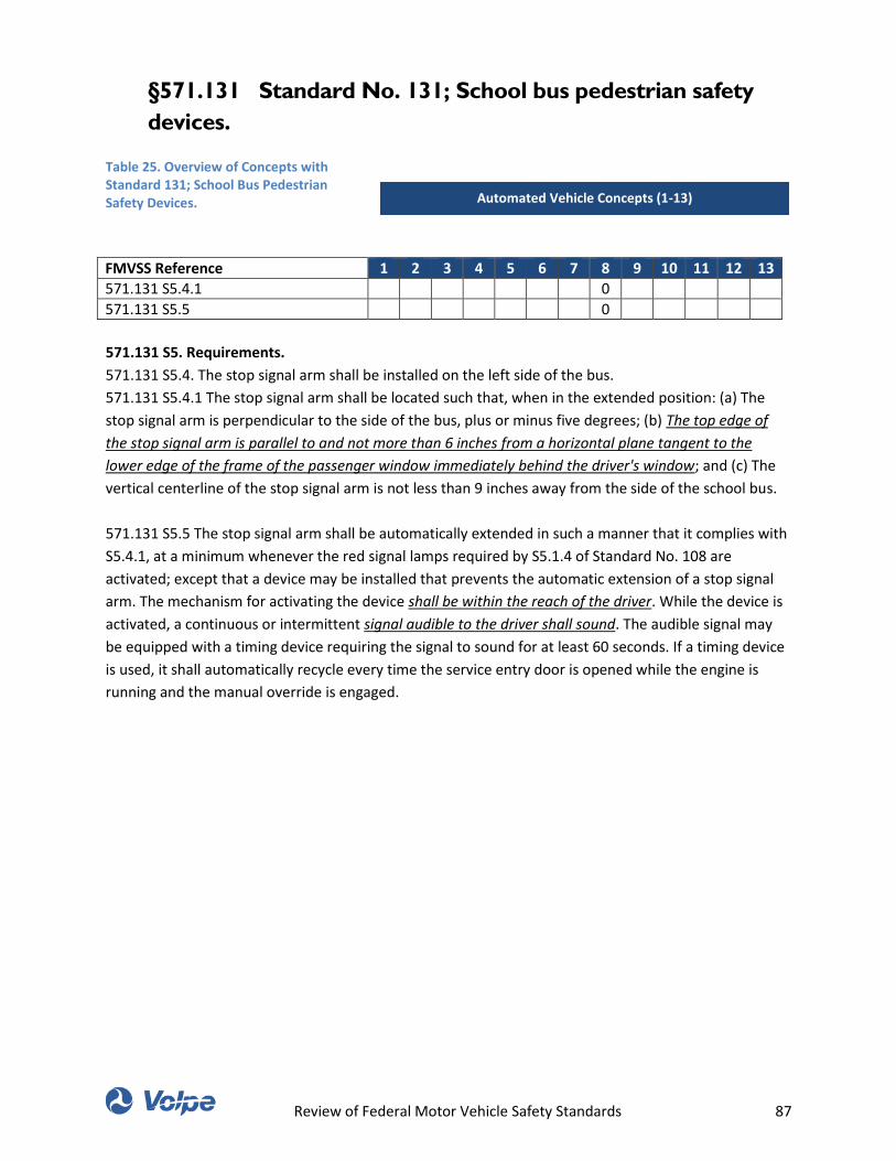
Review of Federal Motor Vehicle Safety Standards 87
§571.131 Standard No. 131; School bus pedestrian safety
devices.
Table 25. Overview of Concepts with Standard 131; School Bus Pedestrian Safety Devices.
FMVSS Reference 1 2 3 4 5 6 7 8 9 10 11 12 13
571.131 S5.4.1 0
571.131 S5.5 0
571.131 S5. Requirements.
571.131 S5.4. The stop signal arm shall be installed on the left side of the bus.
571.131 S5.4.1 The stop signal arm shall be located such that, when in the extended position: (a) The
stop signal arm is perpendicular to the side of the bus, plus or minus five degrees; (b) The top edge of
the stop signal arm is parallel to and not more than 6 inches from a horizontal plane tangent to the
lower edge of the frame of the passenger window immediately behind the driver's window; and (c) The
vertical centerline of the stop signal arm is not less than 9 inches away from the side of the school bus.
571.131 S5.5 The stop signal arm shall be automatically extended in such a manner that it complies with
S5.4.1, at a minimum whenever the red signal lamps required by S5.1.4 of Standard No. 108 are
activated; except that a device may be installed that prevents the automatic extension of a stop signal
arm. The mechanism for activating the device shall be within the reach of the driver. While the device is
activated, a continuous or intermittent signal audible to the driver shall sound. The audible signal may
be equipped with a timing device requiring the signal to sound for at least 60 seconds. If a timing device
is used, it shall automatically recycle every time the service entry door is opened while the engine is
running and the manual override is engaged.
Automated Vehicle Concepts (1-13)
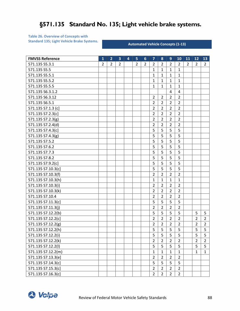
Review of Federal Motor Vehicle Safety Standards 88
§571.135 Standard No. 135; Light vehicle brake systems.
Table 26. Overview of Concepts with Standard 135; Light Vehicle Brake Systems.
FMVSS Reference 1 2 3 4 5 6 7 8 9 10 11 12 13
571.135 S5.3.1 2 2 2 2 2 2 2 2 2 2 2 2
571.135 S5.5 1 1 1 1
571.135 S5.5.1 1 1 1 1
571.135 S5.5.2 1 1 1 1
571.135 S5.5.5 1 1 1 1
571.135 S6.3.1.2 4 4
571.135 S6.3.12 2 2 2 2
571.135 S6.5.1 2 2 2 2
571.135 S7.1.3 (c] 2 2 2 2
571.135 S7.2.3(c] 2 2 2 2
571.135 S7.2.3(g) 2 2 2 2
571.135 S7.2.4(d) 2 2 2 2
571.135 S7.4.3(c] 5 5 5 5
571.135 S7.4.3(g) 5 5 5 5
571.135 S7.5.2 5 5 5 5
571.135 S7.6.2 5 5 5 5
571.135 S7.7.3 5 5 5 5
571.135 S7.8.2 5 5 5 5
571.135 S7.9.2(c] 5 5 5 5
571.135 S7.10.3(c] 5 5 5 5
571.135 S7.10.3(f) 2 2 2 2
571.135 S7.10.3(h) 1 1 1 1
571.135 S7.10.3(i) 2 2 2 2
571.135 S7.10.3(k) 2 2 2 2
571.135 S7.10.4 2 2 2 2
571.135 S7.11.3(c] 5 5 5 5
571.135 S7.11.3(j) 2 2 2 2
571.135 S7.12.2(b) 5 5 5 5 5 5
571.135 S7.12.2(c] 2 2 2 2 2 2
571.135 S7.12.2(g) 2 2 2 2 2 2
571.135 S7.12.2(h) 5 5 5 5 5 5
571.135 S7.12.2(i) 5 5 5 5 5 5
571.135 S7.12.2(k) 2 2 2 2 2 2
571.135 S7.12.2(l) 5 5 5 5 5 5
571.135 S7.12.2(m) 1 1 1 1 1 1
571.135 S7.13.3(e] 2 2 2 2
571.135 S7.14.3(c] 5 5 5 5
571.135 S7.15.3(c] 2 2 2 2
571.135 S7.16.3(c] 2 2 2 2
Automated Vehicle Concepts (1-13)
Review of Federal Motor Vehicle Safety Standards 89
571.135 S4. Definitions.
571.135 S4. Brake power assist unit means a device installed in a hydraulic brake system that reduces
the amount of muscular force that a driver must apply to actuate the system, and that, if inoperative,
does not prevent the driver from braking the vehicle by a continued application of muscular force on the
service brake control.
571.135 S4. Lightly loaded vehicle weight or LLVW means unloaded vehicle weight plus the weight of a
mass of 180 kg (396 pounds), including driver and instrumentation.
571.135 S5. Equipment requirements.
571.135 S5.1 Service brake system. Each vehicle shall be equipped with a service brake system acting on
all wheels.
571.135 S5.1.2. Wear status. The wear condition of all service brakes shall be indicated by either: (a)
Acoustic or optical devices warning the driver at his or her driving position when lining replacement is
necessary, or (b) A means of visually checking the degree of brake lining wear, from the outside or
underside of the vehicle, utilizing only the tools or equipment normally supplied with the vehicle. The
removal of wheels is permitted for this purpose.
571.135 S5.1.3 Regenerative braking system. (a) For an EV equipped with RBS, the RBS is considered to
be part of the service brake system if it is automatically activated by an application of the service brake
control, if there is no means provided for the driver to disconnect or otherwise deactivate it, and if it is
activated in all transmission positions, including neutral. (b) For an EV that is equipped with both ABS
and RBS that is part of the service brake system, the ABS must control the RBS.
571.135 S5.3 Controls.
571.135 S5.3.1 The service brakes shall be activated by means of a foot control. The control of the
parking brake shall be independent of the service brake control, and may be either a hand or foot
control.
571.135 S5.5 Brake system warning indicator. Each vehicle shall have one or more visual brake system
warning indicators, mounted in front of and in clear view of the driver, which meet the requirements of
S5.5.1 through S5.5.5. In addition, a vehicle manufactured without a split service brake system shall be
equipped with an audible warning signal that activates under the conditions specified in S5.5.1(a).
571.135 S5.5.1 Activation. An indicator shall be activated when the ignition (start) switch is in the “on”
(“run”) position and whenever any of conditions (a) through (g) occur: (a) A gross loss of fluid or fluid
pressure (such as caused by rupture of a brake line but not by a structural failure of a housing that is
common to two or more subsystems) as indicated by one of the following conditions (chosen at the
option of the manufacturer): (1) A drop in the level of the brake fluid in any master cylinder reservoir
compartment to less than the recommended safe level specified by the manufacturer or to one-fourth
of the fluid capacity of that reservoir compartment, whichever is greater. (2) For vehicles equipped with
a split service brake system, a differential pressure of 1.5 MPa (218 psi) between the intact and failed
brake subsystems measured at a master cylinder outlet or a slave cylinder outlet. (3) A drop in the
Review of Federal Motor Vehicle Safety Standards 90
supply pressure in a brake power unit to one-half of the normal system pressure. (b) Any electrical
functional failure in an antilock or variable brake proportioning system. (c) Application of the parking
brake. (d) Brake lining wear-out, if the manufacturer has elected to use an electrical device to provide an
optical warning to meet the requirements of S5.1.2(a). (e) For a vehicle with electrically-actuated service
brakes, failure of the source of electric power to those brakes, or diminution of state of charge of the
batteries to less than a level specified by the manufacturer for the purpose of warning a driver of
degraded brake performance. (f) For a vehicle with electric transmission of the service brake control
signal, failure of a brake control circuit. (g) For an EV with a regenerative braking system that is part of
the service brake system, failure of the RBS.
571.135 S5.5.2. Function check. (a) All indicators shall be activated as a check function by either: (1)
Automatic activation when the ignition (start) switch is turned to the “on” (“run”) position when the
engine is not running, or when the ignition (“start”) switch is in a position between “on” (“run”) and
“start” that is designated by the manufacturer as a check position, or (2) A single manual action by the
driver, such as momentary activation of a test button or switch mounted on the instrument panel in front
of and in clear view of the driver, or, in the case of an indicator for application of the parking brake, by
applying the parking brake when the ignition is in the “on” (“run”) position. (b) In the case of a vehicle
that has an interlock device that prevents the engine from being started under one or more conditions,
check functions meeting the requirements of S5.5.2(a) need not be operational under any condition in
which the engine cannot be started. (c) The manufacturer shall explain the brake check function test
procedure in the owner's manual.
571.135 S5.5.5. Labeling. (a) Each visual indicator shall display a word or words in accordance with the
requirements of Standard No. 101 (49 CFR 571.101) and this section, which shall be legible to the driver
under all daytime and nighttime conditions when activated. Unless otherwise specified, the words shall
have letters not less than 3.2 mm ( 1⁄8 inch) high and the letters and background shall be of contrasting
colors, one of which is red. Words or symbols in addition to those required by Standard No. 101 and this
section may be provided for purposes of clarity.
571.135 S6. General test conditions.
571.135 S6.3. Vehicle conditions.
571.135 S6.3.1. Vehicle weight.
571.135 S6.3.1.2 For the test at LLVW, the vehicle is loaded to its LLVW such that the added weight is
distributed in the front passenger seat area.
571.135 S6.3.12 State of charge of batteries for electrically-actuated service brakes. A vehicle equipped
with electrically-actuated service brakes also performs the following test series. Conduct 10 stopping
tests from a speed of 100 kph or the maximum vehicle speed, whichever is less. At least two of the 10
stopping distances must be less than or equal to 70 meters. The vehicle is loaded to GVWR and the
transmission is in the neutral position when the service brake control is actuated and throughout the
remainder of the test. Each battery providing power to the electrically-actuated service brakes, shall be
in a depleted state of charge for conditions (a), (b), or (c) of this paragraph as appropriate. An auxiliary
means may be used to accelerate an EV to test speed.
571.135 S6.5 Procedural conditions.
Review of Federal Motor Vehicle Safety Standards 91
571.135 S6.5.1 Brake control. All service brake system performance requirements, including the partial
system requirements of S7.7, S7.10 and S7.11, must be met solely by use of the service brake control.
571.135 S7. Road test procedures and performance requirements.
571.135 S7.1 Burnish.
571.135 S7.1.3 Test conditions and procedures. The road test surface conditions specified in S6.2 do not
apply to the burnish procedure. (a) IBT: ≤100 °C (212 °F). (b) Test speed: 80 km/h (49.7 mph). (c) Pedal
force: Adjust as necessary to maintain specified constant deceleration rate. (d) Deceleration rate:
Maintain a constant deceleration rate of 3.0 m/s2 (9.8 fps2). (e) Wheel lockup: No lockup of any wheel
allowed for longer than 0.1 seconds at speeds greater than 15 km/h (9.3 mph). (f) Number of runs: 200
stops. (g) Interval between runs: The interval from the start of one service brake application to the start
of the next is either the time necessary to reduce the IBT to 100 °C (212 °F) or less, or the distance of 2
km (1.24 miles), whichever occurs first. (h) Accelerate to 80 km/h (49.7 mph) after each stop and
maintain that speed until making the next stop. (i) After burnishing, adjust the brakes as specified in
S6.3.4.
571.135 S7.2 Wheel lockup sequence.
571.135 S7.2.3 Test Conditions and Procedures. (a) IBT: ≤65 °C (149 °F), ≤100 °C (212 °F). (b) Test speed:
65 km/h (40.4 mph) for a braking ratio ≤0.50; 100 km/h (62.1 mph) for a braking ratio >0.50. (c) Pedal
force: (1) Pedal force is applied and controlled by the vehicle driver or by a mechanical brake pedal
actuator. (2) Pedal force is increased at a linear rate such that the first axle lockup occurs no less than
one-half (0.5) second and no more than one and one-half (1.5) seconds after the initial application of the
pedal. (3) The pedal is released when the second axle locks, or when the pedal force reaches 1kN (225
lbs), or 0.1 seconds after first axle lockup, whichever occurs first. (d) Wheel lockup: Only wheel lockups
above a vehicle speed of 15 km/h (9.3 mph) are considered in determining the results of this test. (e)
Test surfaces: This test is conducted, for each loading condition, on two different test surfaces that will
result in a braking ratio of between 0.15 and 0.80, inclusive. NHTSA reserves the right to choose the test
surfaces to be used based on adhesion utilization curves or any other method of determining “worst
case” conditions. (f) The data recording equipment shall have a minimum sampling rate of 40 Hz. (g)
Data to be recorded. The following information must be automatically recorded in phase continuously
throughout each test run such that values of the variables can be cross referenced in real time. (1)
Vehicle speed. (2) Brake pedal force. (3) Angular velocity at each wheel. (4) Actual instantaneous vehicle
deceleration or the deceleration calculated by differentiation of the vehicle speed. (h) Speed channel
filtration. For analog instrumentation, the speed channel shall be filtered by using a low-pass filter
having a cut-off frequency of less than one fourth the sampling rate. (i) Test procedure. For each test
surface, three runs meeting the pedal force application and time for wheel lockup requirements shall be
made. Up to a total of six runs will be allowed to obtain three valid runs. Only the first three valid runs
obtained shall be used for data analysis purposes.
571.135 S7.2.4. Performance requirements. (a) In order to pass this test a vehicle shall be capable of
meeting the test requirements on all test surfaces that will result in a braking ratio of between 0.15 and
0.80, inclusive. (b) If all three valid runs on each surface result in the front axle locking before or
simultaneously with the rear axle, or the front axle locks up with only one or no wheels locking on the
rear axle, the torque wheel procedure need not be run, and the vehicle is considered to meet the
Review of Federal Motor Vehicle Safety Standards 92
adhesion utilization requirements of this Standard. This performance requirement shall be met for all
vehicle braking ratios between 0.15 and 0.80. (c) If any one of the three valid runs on any surface results
in the rear axle locking before the front axle or the rear axle locks up with only one or no wheels locking
on the front axle the torque wheel procedure shall be performed. This performance requirement shall
be met for all vehicle braking ratios between 0.15 and 0.80. (d) If any one of the three valid runs on any
surface results in neither axle locking (i.e., only one or no wheels locked on each axle) before a pedal
force of 1kN (225 lbs) is reached, the vehicle shall be tested to the torque wheel procedure. (e) If the
conditions listed in paragraph (c) or (d) of this section occur, vehicle compliance shall be determined
from the results of a torquesults of a torque wheel test performed in accordance with S7.4. (f) An EV
with RBS that is part of the service brake system shall meet the performance requirements over the
entire normal operating range of the RBS.
571.135 S7.4 Adhesion utilization (Torque Wheel Method).
571.135 S7.4.3 Test conditions and procedures. (a) IBT: ≤65 °C (149 °F), ≤100 °C (212 °F). (b) Test speeds:
100 km/h (62.1 mph), and 50 km/h (31.1 mph). (c) Pedal force: Pedal force is increased at a linear rate
between 100 and 150 N/sec (22.5 and 33.7 lbs/sec) for the 100 km/h test speed, or between 100 and 200
N/sec (22.5 and 45.0 lbs/sec) for the 50 km/h test speed, until the first axle locks or until a pedal force of
1 kN (225 lbs) is reached, whichever occurs first. (d) Cooling: Between brake applications, the vehicle is
driven at speeds up to 100 km/h (62.1 mph) until the IBT specified in S7.4.3(a) is reached. (e) Number of
runs: With the vehicle at LLVW, run five stops from a speed of 100 km/h (62.1 mph) and five stops from
a speed of 50 km/h (31.1 mph), while alternating between the two test speeds after each stop. With the
vehicle at GVWR, repeat the five stops at each test speed while alternating between the two test
speeds. (f) Test surface: PFC of at least 0.9. (g) Data to be recorded. The following information must be
automatically recorded in phase continuously throughout each test run such that values of the variables
can be cross referenced in real time: (1) Vehicle speed. (2) Brake pedal force. (3) Angular velocity at each
wheel. (4) Brake torque at each wheel. (5) Hydraulic brake line pressure in each brake circuit.
Hydraulically proportioned circuits shall be fitted with transducers on at least one front wheel and one
rear wheel downstream of the operative proportioning or pressure limiting valve(s). (6) Vehicle
deceleration. (h) Sample rate: All data acquisition and recording equipment shall support a minimum
sample rate of 40 Hz on all channels. (i) Determination of front versus rear brake pressure. Determine
the front versus rear brake pressure relationship over the entire range of line pressures. Unless the
vehicle has a variable brake proportioning system, this determination is made by static test. If the
vehicle has a variable brake proportioning system, dynamic tests are run with the vehicle both empty
and loaded. 15 snubs from 50 km/h (31.1 mph) are made for each of the two load conditions, using the
same initial conditions specified in this section.
571.135 S7.5 Cold effectiveness.
571.135 S7.5.2. Test conditions and procedures. (a) IBT: ≤65 °C (149 °F), ≤100 °C (212 °F). (b) Test speed:
100 km/h (62.1 mph). (c) Pedal force: ≤65N (14.6 lbs), ≤500N (112.4 lbs). (d) Wheel lockup: No lockup of
any wheel for longer than 0.1 seconds allowed at speeds greater than 15 km/h (9.3 mph). (e) Number of
runs: 6 stops. (f) Test surface: PFC of 0.9. (g) For each stop, bring the vehicle to test speed and then stop
the vehicle in the shortest possible distance under the specified conditions.
571.135 S7.6 High speed effectiveness.
Review of Federal Motor Vehicle Safety Standards 93
571.135 S7.6.2. Test conditions and procedures. (a) IBT: ≤65 °C (149 °F), ≤100 °C (212 °F). (b) Test speed:
80% of vehicle maximum speed if 125 km/h (77.7 mph) <vehicle maximum speed <200 km/h (124.3
mph), or 160 km/h (99.4 mph) if vehicle maximum speed ≤200 km/h (124.3 mph). (c) Pedal force: ≤65N
(14.6 lbs), ≤500N (112.4 lbs). (d) Wheel lockup: No lockup of any wheel for longer than 0.1 seconds
allowed at speeds greater than 15 km/h (9.3 mph). (e) Number of runs: 6 stops. (f) Test surface: PFC of
0.9.
571.135 S7.7 Stops with Engine off.
571.135 S7.7.3. Test conditions and procedures. (a) IBT: ≤65 °C (149 °F), ≤100 °C (212 °F). (b) Test speed:
100 km/h (62.1 mph). (c) Pedal force: ≤65N (14.6 lbs), ≤500N (112.4 lbs). (d) Wheel lockup: No lockup of
any wheel allowed for longer than 0.1 seconds at speeds greater than 15 km/h (9.3 mph). (e) Number of
runs: 6 stops. (f) Test surface: PFC of 0.9. (g) All system reservoirs (brake power and/or assist units) are
fully charged and the vehicle's engine is off (not running) at the beginning of each stop. (h) For an EV,
this test is conducted with no electrical power supplied to the vehicle's propulsion motor(s), but with
the RBS and brake power or power assist still operating, unless cutting off the supply of electrical power
to the propulsion motor(s) also disables those systems.
571.135 S7.8 Antilock function failure.
571.135 S7.8.2 Test conditions and procedures. (a) IBT: ≤65 °C (149 °F), ≤100 °C (212 °F). (b) Test speed:
100 km/h (62.1 mph). (c) Pedal force: ≤65 N (14.6 lbs), ≤500 N (112.4 lbs). (d) Wheel lockup: No lockup
of any wheel for more than 0.1 seconds allowed at speeds greater than 15 km/h (9.3 mph). (e) Number
of runs: 6 stops. (f) Test surface: PFC of 0.9. (g) Functional failure simulation: (1) Disconnect the
functional power source, or any other electrical connector that creates a functional failure. (2)
Determine whether the brake system indicator is activated when any electrical functional failure of the
antilock system is created. (3) Restore the system to normal at the completion of this test. (h) If more
than one antilock brake subsystem is provided, repeat test for each subsystem.
571.135 S7.9 Variable brake proportioning system functional failure.
571.135 S7.9.2. Test conditions and procedures. (a) IBT: ≤65 °C (149 °F), ≤100 °C (212 °F). (b) Test speed:
100 km/h (62.1 mph). (c) Pedal force: ≤65 N (14.6 lbs), ≤500 N (112.4 lbs). (d) Wheel lockup: No lockup
of any wheel for longer than 0.1 seconds allowed at speeds greater than 15 km/h (9.3 mph). (e) Number
of runs: 6 stops. (f) Test surface: PFC of 0.9. (g) Functional failure simulation: (1) Disconnect the
functional power source or mechanical linkage to render the variable brake proportioning system
inoperative. (2) If the system utilizes electrical components, determine whether the brake system
indicator is activated when any electrical functional failure of the variable proportioning system is
created. (3) Restore the system to normal at the completion of this test. (h) If more than one variable
brake proportioning subsystem is provided, repeat the test for each subsystem.
571.135 S7.10 Hydraulic circuit failure.
571.135 S7.10.3 Test conditions and procedures. (a) IBT: ≤65 °C (149 °F), ≤100 °C (212 °F). (b) Test speed:
100 km/h (62.1 mph). (c) Pedal force: ≤65N (14.6 lbs), ≤500 N (112.4 lbs). (d) Wheel lockup: No lockup of
any wheel for longer than 0.1 seconds allowed at speeds greater than 15 km/h (9.3 mph). (e) Test
surface: PFC of 0.9. (f) Alter the service brake system to produce any single failure. For a hydraulic
circuit, this may be any single rupture or leakage type failure, other than a structural failure of a housing
Review of Federal Motor Vehicle Safety Standards 94
that is common to two or more subsystems. For a vehicle in which the brake signal is transmitted
electrically between the brake pedal and some or all of the foundation brakes, regardless of the means
of actuation of the foundation brakes, this may be any single failure in any circuit that electrically
transmits the brake signal. For an EV with RBS that is part of the service brake system, this may be any
single failure in the RBS. (g) Determine the control force pressure level or fluid level (as appropriate for
the indicator being tested) necessary to activate the brake warning indicator. (h) Number of runs: After
the brake warning indicator has been activated, make the following stops depending on the type of
brake system: (1) 4 stops for a split service brake system. (2) 10 consecutive stops for a non-split service
brake system. (i) Each stop is made by a continuous application of the service brake control. (j) Restore
the service brake system to normal at the completion of this test. (k) Repeat the entire sequence for
each of the other subsystems.
571.135 S7.10.4 Performance requirements. For vehicles manufactured with a split service brake
system, in the event of any failure in a single subsystem, as specified in S7.10.3(f) of this standard, and
after activation of the brake system indicator as specified in S5.5.1, the remaining portions of the service
brake system shall continue to operate and shall stop the vehicle as specified in S7.10.4(a) or S7.10.4(b).
For vehicles not manufactured with a split service brake system, in the event of any failure in any
component of the service brake system, as specified in S7.10.3(f), and after activation of the brake
system indicator as specified in S5.5.1 of this standard, the vehicle shall, by operation of the service brake
control, stop 10 times consecutively as specified in S7.10.4(a) or S7.10.4(b). (a) Stopping distance from
100 km/h test speed: ≤168 m (551 ft). (b) Stopping distance for reduced test speed: S ≤0.10V +
0.0158V2.
571.135 S7.11. Brake power unit or brake power assist unit inoperative (System depleted).
571.135 S7.11.3. Test conditions and procedures. (a) IBT: ≤65 °C (149 °F), ≤100 °C (212 °F). (b) Test
speed: 100 km/h (62.1 mph). (c) Pedal force: ≤65 N (14.6 lbs), ≤500 N (112.4 lbs). (d) Wheel lockup: No
lockup of any wheel for longer than 0.1 seconds allowed at speeds greater than 15 km/h (9.3 mph). (e)
Number of runs: 6 stops. (f) Test surface: PFC of 0.9. (g) Disconnect the primary source of power for one
brake power assist unit or brake power unit, or one of the brake power unit or brake power assist unit
subsystems if two or more subsystems are provided. (h) If the brake power unit or power assist unit
operates in conjunction with a backup system and the backup system is automatically activated in the
event of a primary power service failure, the backup system is operative during this test. (i) Exhaust any
residual brake power reserve capability of the disconnected system. (j) Make each of the 6 stops by a
continuous application of the service brake control. (k) Restore the system to normal at completion of
this test. (l) For vehicles equipped with more than one brake power unit or brake power assist unit,
conduct tests for each in turn. (m) For vehicles with electrically-actuated service brakes (brake power
unit), this test is conducted with any single electrical failure in the electrically-actuated service brakes
instead of a failure of any other brake power or brake power assist unit, and all other systems intact.
571.135 S7.12. Parking brake.
571.135 S7.12.2. Test conditions and procedures. (a) IBT: (1) Parking brake systems utilizing service
brake friction materials shall be tested with the IBT ≤100 °C (212 °F) and shall have no additional
burnishing or artificial heating prior to the start of the parking brake test. (2) Parking brake systems
utilizing non-service brake friction materials shall be tested with the friction materials at ambient
temperature at the start of the test. The friction materials shall have no additional burnishing or artificial
Review of Federal Motor Vehicle Safety Standards 95
heating prior to or during the parking brake test. (b) Parking brake control force: Hand control ≤400 N
(89.9 lbs); foot control ≤500 N (112.4 lbs). (c) Hand force measurement locations: The force required for
actuation of a hand-operated brake system is measured at the center of the hand grip area or at a
distance of 40 mm (1.57 in) from the end of the actuation lever as illustrated in Figure 3. (d) Parking
brake applications: 1 application and up to 2 reapplications, if necessary. (e) Test surface gradient: 20%
grade. (f) Drive the vehicle onto the grade with the longitudinal axis of the vehicle in the direction of the
slope of the grade. (g) Stop the vehicle and hold it stationary by applying the service brake control and
place the transmission in neutral. (h) With the service brake applied sufficiently to just keep the vehicle
from rolling, apply the parking brake as specified in S7.12.2(i) or S7.12.2(j). (i) For a vehicle equipped with
mechanically-applied parking brakes, make a single application of the parking brake control with a force
not exceeding the limits specified in S7.12.2(b). For a vehicle using an electrically-activated parking
brake, apply the parking brake by activating the parking brake control. (j) In the case of a parking brake
system that does not allow application of the specified force in a single application, a series of
applications may be made to achieve the specified force. (k) Following the application of the parking
brakes, release all force on the service brake control and, if the vehicle remains stationary, start the
measurement of time. (l) If the vehicle does not remain stationary, reapplication of a force to the parking
brake control at the level specified in S7.12.2(b) as appropriate for the vehicle being tested (without
release of the ratcheting or other holding mechanism of the parking brake) is used up to two times to
attain a stationary position. (m) Verify the operation of the parking brake application indicator. (n)
Following observation of the vehicle in a stationary condition for the specified time in one direction,
repeat the same test procedure with the vehicle orientation in the opposite direction on the same
grade.
571.135 S7.13. Heating Snubs.
571.135 S7.13.3. Test conditions and procedures. (a) IBT: (1) Establish an IBT before the first brake
application (snub) of ≤55 °C (131 °F), ≤65 °C (149 °F). (2) IBT before subsequent snubs are those
occurring at the distance intervals. (b) Number of snubs: 15. (c) Test speeds: The initial speed for each
snub is 120 km/h (74.6 mph) or 80% of Vmax, whichever is slower. Each snub is terminated at one-half
the initial speed. (d) Deceleration rate: (1) Maintain a constant deceleration rate of 3.0 m/s2 (9.8 fps2).
(2) Attain the specified deceleration within one second and maintain it for the remainder of the snub. (e)
Pedal force: Adjust as necessary to maintain the specified constant deceleration rate. (f) Time interval:
Maintain an interval of 45 seconds between the start of brake applications (snubs). (g) Accelerate as
rapidly as possible to the initial test speed immediately after each snub. (h) Immediately after the 15th
snub, accelerate to 100 km/h (62.1 mph) and commence the hot performance test.
571.135 S7.14. Hot performance.
571.135 S7.14.3 Test conditions and procedures. (a) IBT: Temperature achieved at completion of heating
snubs. (b) Test speed: 100 km/h (62.1 mph). (c) Pedal force: (1) The first stop is done with an average
pedal force not greater than the average pedal force recorded during the shortest GVWR cold
effectiveness stop. (2) The second stop is done with a pedal force not greater than 500 N (112.4 lbs). (d)
Wheel lockup: No lockup of any wheel for longer than 0.1 seconds allowed at speeds greater than 15
km/h (9.3 mph). (e) Number of runs: 2 stops. (f) Immediately after the 15th heating snub, accelerate to
100 km/h (62.1 mph) and commence the first stop of the hot performance test. (g) If the vehicle is
incapable of attaining 100 km/h, it is tested at the same speed used for the GVWR cold effectiveness
Review of Federal Motor Vehicle Safety Standards 96
test. (h) Immediately after completion of the first hot performance stop, accelerate as rapidly as
possible to the specified test speed and conduct the second hot performance stop. (i) Immediately after
completion of the second hot performance stop, drive 1.5 km (0.93 mi) at 50 km/h (31.1 mph) before
the first cooling stop.
571.135 S7.15. Brake cooling stops.
571.135 S7.15.3. Test conditions and procedures. (a) IBT: Temperature achieved at completion of hot
performance. (b) Test speed: 50 km/h (31.1 mph). (c) Pedal force: Adjust as necessary to maintain
specified constant deceleration rate. (d) Deceleration rate: Maintain a constant deceleration rate of 3.0
m/s2 (9.8 fps2). (e) Wheel lockup: No lockup of any wheel for longer than 0.1 seconds allowed at speeds
greater than 15 km/h (9.3 mph). (f) Number of runs: 4 stops. (g) Immediately after the hot performance
stops drive 1.5 km (0.93 mi) at 50 km/h (31.1 mph) before the first cooling stop. (h) For the first through
the third cooling stops: (1) After each stop, immediately accelerate at the maximum rate to 50 km/h
(31.1 mph). (2) Maintain that speed until beginning the next stop at a distance of 1.5 km (0.93 mi) from
the beginning of the previous stop. (i) For the fourth cooling stop: (1) Immediately after the fourth stop,
accelerate at the maximum rate to 100 km/h (62.1 mph). (2) Maintain that speed until beginning the
recovery performance stops at a distance of 1.5 km (0.93 mi) after the beginning of the fourth cooling
stop.
571.135 S7.16. Recovery performance.
571.135 S7.16.3. Test conditions and procedures. (a) IBT: Temperature achieved at completion of
cooling stops. (b) Test speed: 100 km/h (62.1 mph). (c) Pedal force: The average pedal force shall not be
greater than the average pedal force recorded during the shortest GVWR cold effectiveness stop. (d)
Wheel lockup: No lockup of any wheel for longer than 0.1 seconds allowed at speeds greater than 15
km/h (9.3 mph). (e) Number of runs: 2 stops. (f) Immediately after the fourth cooling stop, accelerate at
the maximum rate to 100 km/h (62.1 mph). (g) Maintain that speed until beginning the first recovery
performance stop at a distance of 1.5 km (0.93 mi) after the beginning of the fourth cooling stop. (h) If
the vehicle is incapable of attaining 100 km/h, it is tested at the same speed used for the GVWR cold
effectiveness test. (i) Immediately after completion of the first recovery performance stop accelerate as
rapidly as possible to the specified test speed and conduct the second recovery performance stop.
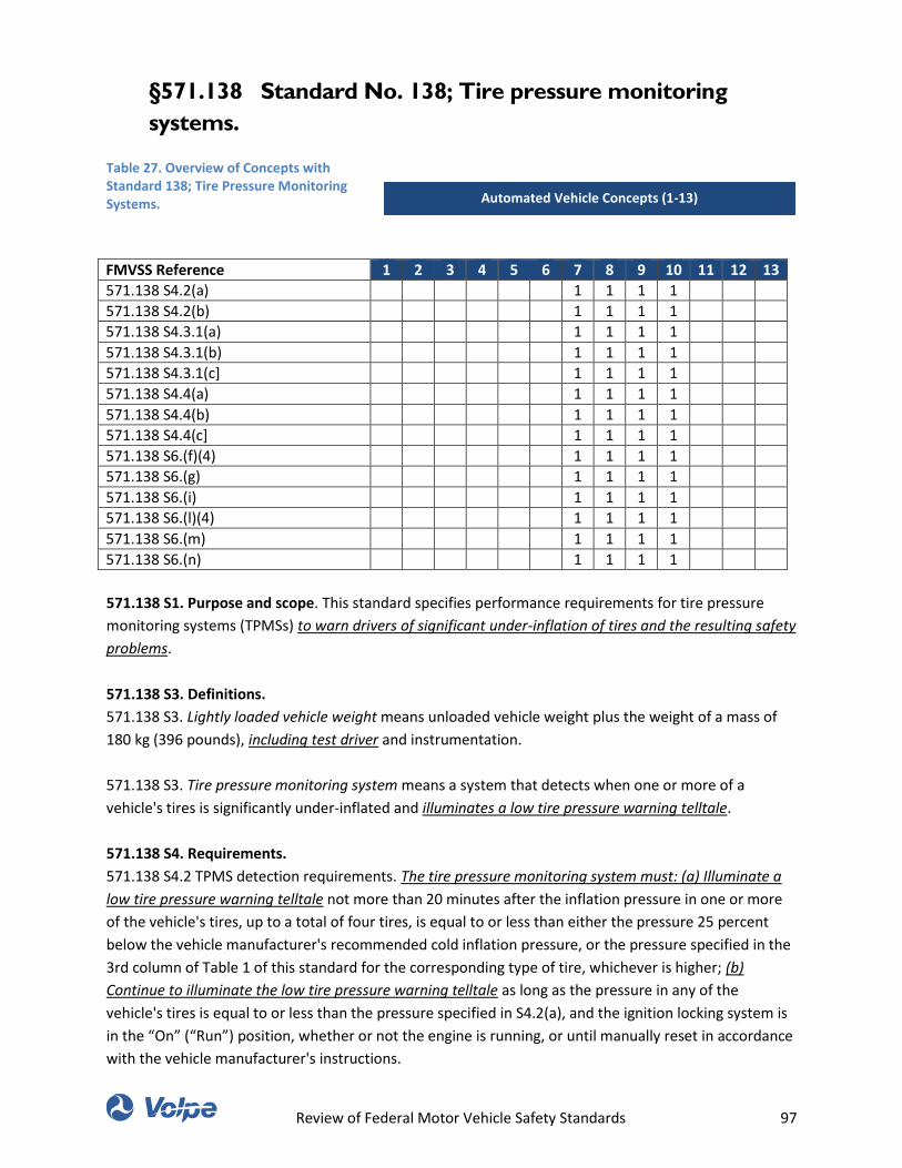
Review of Federal Motor Vehicle Safety Standards 97
§571.138 Standard No. 138; Tire pressure monitoring
systems.
Table 27. Overview of Concepts with Standard 138; Tire Pressure Monitoring Systems.
FMVSS Reference 1 2 3 4 5 6 7 8 9 10 11 12 13
571.138 S4.2(a) 1 1 1 1
571.138 S4.2(b) 1 1 1 1
571.138 S4.3.1(a) 1 1 1 1
571.138 S4.3.1(b) 1 1 1 1
571.138 S4.3.1(c] 1 1 1 1
571.138 S4.4(a) 1 1 1 1
571.138 S4.4(b) 1 1 1 1
571.138 S4.4(c] 1 1 1 1
571.138 S6.(f)(4) 1 1 1 1
571.138 S6.(g) 1 1 1 1
571.138 S6.(i) 1 1 1 1
571.138 S6.(l)(4) 1 1 1 1
571.138 S6.(m) 1 1 1 1
571.138 S6.(n) 1 1 1 1
571.138 S1. Purpose and scope. This standard specifies performance requirements for tire pressure
monitoring systems (TPMSs) to warn drivers of significant under-inflation of tires and the resulting safety
problems.
571.138 S3. Definitions.
571.138 S3. Lightly loaded vehicle weight means unloaded vehicle weight plus the weight of a mass of
180 kg (396 pounds), including test driver and instrumentation.
571.138 S3. Tire pressure monitoring system means a system that detects when one or more of a
vehicle's tires is significantly under-inflated and illuminates a low tire pressure warning telltale.
571.138 S4. Requirements.
571.138 S4.2 TPMS detection requirements. The tire pressure monitoring system must: (a) Illuminate a
low tire pressure warning telltale not more than 20 minutes after the inflation pressure in one or more
of the vehicle's tires, up to a total of four tires, is equal to or less than either the pressure 25 percent
below the vehicle manufacturer's recommended cold inflation pressure, or the pressure specified in the
3rd column of Table 1 of this standard for the corresponding type of tire, whichever is higher; (b)
Continue to illuminate the low tire pressure warning telltale as long as the pressure in any of the
vehicle's tires is equal to or less than the pressure specified in S4.2(a), and the ignition locking system is
in the “On” (“Run”) position, whether or not the engine is running, or until manually reset in accordance
with the vehicle manufacturer's instructions.
Automated Vehicle Concepts (1-13)
Review of Federal Motor Vehicle Safety Standards 98
571.138 S4.3 Low tire pressure warning telltale.
571.138 S4.3.1 Each tire pressure monitoring system must include a low tire pressure warning telltale
that: (a) Is mounted inside the occupant compartment in front of and in clear view of the driver; (b) Is
identified by one of the symbols shown for the “Low Tire Pressure” Telltale in Table 1 of Standard No. 101
(49 CFR 571.101); and (c) Is illuminated under the conditions specified in S4.2.
571.138 S4.4 TPMS malfunction. (a) The vehicle shall be equipped with a tire pressure monitoring system
that includes a telltale that provides a warning to the driver not more than 20 minutes after the
occurrence of a malfunction that affects the generation or transmission of control or response signals in
the vehicle's tire pressure monitoring system. The vehicle's TPMS malfunction indicator shall meet the
requirements of either S4.4(b) or S4.4(c). (b) Dedicated TPMS malfunction telltale. The vehicle meets the
requirements of S4.4(a) when equipped with a dedicated TPMS malfunction telltale that: (1) Is mounted
inside the occupant compartment in front of and in clear view of the driver; (2) Is identified by the word
“TPMS” as described under the “Tire Pressure Monitoring System Malfunction” Telltale in Table 1 of
Standard No. 101 (49 CFR 571.101); (3) Continues to illuminate the TPMS malfunction telltale under the
conditions specified in S4.4(a) for as long as the malfunction exists, whenever the ignition locking system
is in the “On” (“Run”) position; and (4) (i) Except as provided in paragraph (ii), each dedicated TPMS
malfunction telltale must be activated as a check of lamp function either when the ignition locking
system is activated to the “On” (“Run”) position when the engine is not running, or when the ignition
locking system is in a position between “On” (“Run”) and “Start” that is designated by the manufacturer
as a check position. (ii) The dedicated TPMS malfunction telltale need not be activated when a starter
interlock is in operation. (c) Combination low tire pressure/TPMS malfunction telltale. The vehicle meets
the requirements of S4.4(a) when equipped with a combined Low Tire Pressure/TPMS malfunction
telltale that: (1) Meets the requirements of S4.2 and S4.3; and (2) Flashes for a period of at least 60
seconds but no longer than 90 seconds upon detection of any condition specified in S4.4(a) after the
ignition locking system is activated to the “On” (“Run”) position. After each period of prescribed flashing,
the telltale must remain continuously illuminated as long as a malfunction exists and the ignition locking
system is in the “On” (“Run”) position. This flashing and illumination sequence must be repeated each
time the ignition locking system is placed in the “On” (“Run”) position until the situation causing the
malfunction has been corrected. Multiple malfunctions occurring during any ignition cycle may, but are
not required to, reinitiate the prescribed flashing sequence.
571.138 S6. Test Procedures. (a) Inflate the vehicle's tires to the cold tire inflation pressure(s) provided
on the vehicle placard or the tire inflation pressure label. (b) With the vehicle stationary and the ignition
locking system in the “Lock” or “Off” position, activate the ignition locking system to the “On” (“Run”)
position or, where applicable, the appropriate position for the lamp check. The tire pressure monitoring
system must perform a check of lamp function for the low tire pressure telltale as specified in paragraph
S4.3.3 of this standard. If the vehicle is equipped with a separate TPMS malfunction telltale, the tire
pressure monitoring system also must perform a check of lamp function as specified in paragraph
S4.4(b)(4) of this standard. (c) If applicable, set or reset the tire pressure monitoring system in
accordance with the instructions in the vehicle owner's manual. (d) System calibration/learning phase.
(1) Drive the vehicle for up to 15 minutes of cumulative time (not necessarily continuously) along any
portion of the test course. (2) Reverse direction on the course and drive the vehicle for an additional
period of time for a total cumulative time of 20 minutes (including the time in S6(d)(1), and not
Review of Federal Motor Vehicle Safety Standards 99
necessarily continuously). (e) Stop the vehicle and deflate any combination of one to four tires until the
deflated tire(s) is (are) at 7 kPa (1 psi) below the inflation pressure at which the tire pressure monitoring
system is required to illuminate the low tire pressure warning telltale. (f) System detection phase. (1)
Within 5 minutes of reducing the inflation pressure in the tire(s), drive the vehicle for up to 10-15
minutes of cumulative time (not necessarily continuously) along any portion of the test course. (2)
Reverse direction on the course and drive the vehicle for an additional period of time for a total
cumulative time of 20 minutes (including the time in S6(f)(1), and not necessarily continuously). (3) The
sum of the total cumulative drive time under paragraphs S6(f)(1) and (2) shall be the lesser of 20
minutes or the time at which the low tire pressure telltale illuminates. (4) If the low tire pressure telltale
did not illuminate, discontinue the test. (g) If the low tire pressure telltale illuminated during the
procedure in paragraph S6(f), deactivate the ignition locking system to the “Off” or “Lock” position. After
a 5-minute period, activate the vehicle's ignition locking system to the “On” (“Run”) position. The telltale
must illuminate and remain illuminated as long as the ignition locking system is in the “On” (“Run”)
position. (h) Keep the vehicle stationary for a period of up to one hour with the engine off. (i) Inflate all
of the vehicle's tires to the same inflation pressure used in paragraph S6(a). If the vehicle's tire pressure
monitoring system has a manual reset feature, reset the system in accordance with the instructions
specified in the vehicle owner's manual. Determine whether the telltale has extinguished. If necessary,
drive the vehicle until the telltale has been extinguished. (j) The test may be repeated, using the test
procedures in paragraphs S6(a)-(b) and S6(d)-(i), with any one, two, three, or four of the tires on the
vehicle under-inflated. (k) Simulate one TPMS malfunction by disconnecting the power source to any
TPMS component, disconnecting any electrical connection between TPMS components, or installing a
tire or wheel on the vehicle that is incompatible with the TPMS. When simulating a TPMS malfunction,
the electrical connections for the telltale lamps are not to be disconnected. (l) TPMS malfunction
detection. (1) Drive the vehicle for up to 15 minutes of cumulative time (not necessarily continuously)
along any portion of the test course. (2) Reverse direction on the course and drive the vehicle for an
additional period of time for a total cumulative time of 20 minutes (including the time in S6(l)(1), and
not necessarily continuously). (3) The sum of the total cumulative drive time under paragraphs S6(l)(1)
and (2) shall be the lesser of 20 minutes or the time at which the TPMS malfunction telltale illuminates.
(4) If the TPMS malfunction indicator did not illuminate in accordance with paragraph S4.4, as required,
discontinue the test. (m) If the TPMS malfunction indicator illuminated during the procedure in
paragraph S6(l), deactivate the ignition locking system to the “Off” or “Lock” position. After a 5-minute
period, activate the vehicle's ignition locking system to the “On” (“Run”) position. The TPMS malfunction
indicator must again signal a malfunction and remain illuminated as long as the ignition locking system is
in the “On” (“Run”) position. (n) Restore the TPMS to normal operation. If necessary, drive the vehicle
until the telltale has extinguished. (o) The test may be repeated using the test procedures in paragraphs
S6(k)-(n), with each such test limited to simulation of a single malfunction.
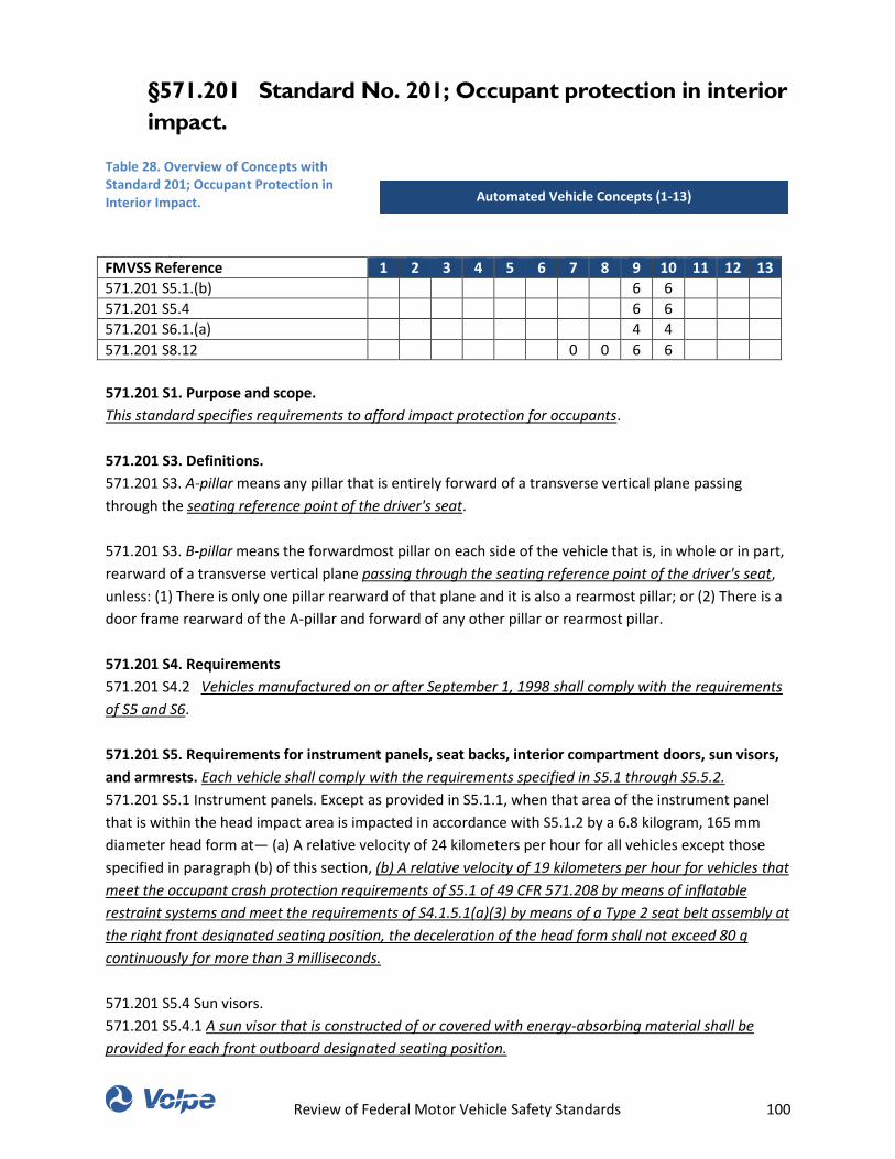
Review of Federal Motor Vehicle Safety Standards 100
§571.201 Standard No. 201; Occupant protection in interior
impact.
Table 28. Overview of Concepts with Standard 201; Occupant Protection in Interior Impact.
FMVSS Reference 1 2 3 4 5 6 7 8 9 10 11 12 13
571.201 S5.1.(b) 6 6
571.201 S5.4 6 6
571.201 S6.1.(a) 4 4
571.201 S8.12 0 0 6 6
571.201 S1. Purpose and scope.
This standard specifies requirements to afford impact protection for occupants.
571.201 S3. Definitions.
571.201 S3. A-pillar means any pillar that is entirely forward of a transverse vertical plane passing
through the seating reference point of the driver's seat.
571.201 S3. B-pillar means the forwardmost pillar on each side of the vehicle that is, in whole or in part,
rearward of a transverse vertical plane passing through the seating reference point of the driver's seat,
unless: (1) There is only one pillar rearward of that plane and it is also a rearmost pillar; or (2) There is a
door frame rearward of the A-pillar and forward of any other pillar or rearmost pillar.
571.201 S4. Requirements
571.201 S4.2 Vehicles manufactured on or after September 1, 1998 shall comply with the requirements
of S5 and S6.
571.201 S5. Requirements for instrument panels, seat backs, interior compartment doors, sun visors,
and armrests. Each vehicle shall comply with the requirements specified in S5.1 through S5.5.2.
571.201 S5.1 Instrument panels. Except as provided in S5.1.1, when that area of the instrument panel
that is within the head impact area is impacted in accordance with S5.1.2 by a 6.8 kilogram, 165 mm
diameter head form at— (a) A relative velocity of 24 kilometers per hour for all vehicles except those
specified in paragraph (b) of this section, (b) A relative velocity of 19 kilometers per hour for vehicles that
meet the occupant crash protection requirements of S5.1 of 49 CFR 571.208 by means of inflatable
restraint systems and meet the requirements of S4.1.5.1(a)(3) by means of a Type 2 seat belt assembly at
the right front designated seating position, the deceleration of the head form shall not exceed 80 g
continuously for more than 3 milliseconds.
571.201 S5.4 Sun visors.
571.201 S5.4.1 A sun visor that is constructed of or covered with energy-absorbing material shall be
provided for each front outboard designated seating position.
Automated Vehicle Concepts (1-13)
Review of Federal Motor Vehicle Safety Standards 101
571.201 S6 Requirements for upper interior components.
571.201 S6.1 Vehicles manufactured on or after September 1, 1998.
571.201 S6.1.(a) When tested under the conditions of S8, comply with the requirements specified in S7 at
the target locations specified in S10 when impacted by the free motion headform specified in S8.9 at any
speed up to and including 24 km/h (15 mph). The requirements do not apply to any target that cannot be
located using the procedures of S10.
571.201 S8 Target location and test conditions.
The vehicle shall be tested and the targets specified in S10 located under the following conditions.
571.201 S8.12 Location of head center of gravity. (a) Location of head center of gravity for front
outboard designated seating positions (CG-F). For determination of head center of gravity, all directions
are in reference to the seat orientation. (1) Location of rearmost CG-F (CG-F2). For front outboard
designated seating positions, the head center of gravity with the seat in its rearmost normal design
driving or riding position (CG-F2) is located 160 mm rearward and 660 mm upward from the seating
reference point. (2) Location of forwardmost CG-F (CG-F1). For front outboard designated seating
positions, the head center of gravity with the seat in its forwardmost adjustment position (CG-F1) is
located horizontally forward of CG-F2 by the distance equal to the fore-aft distance of the seat track. (b)
Location of head center of gravity for rear outboard designated seating positions (CG-R). For rear
outboard designated seating positions, the head center of gravity (CG-R) is located 160 mm rearward,
relative to the seat orientation, and 660 mm upward from the seating reference point.
Review of Federal Motor Vehicle Safety Standards 102
§571.202a Standard No. 202a; Head restraints; Mandatory
applicability begins on September 1, 2009.
Table 29. Overview of Concepts with Standard 202a; Head Restraints; Mandatory Applicability Begins of September 1, 2009.
FMVSS Reference 1 2 3 4 5 6 7 8 9 10 11 12 13
This table was intentionally left blank.
571.202a S4. Requirements.
571.202a S4.1 Performance levels. In each vehicle other than a school bus, a head restraint that
conforms to either S4.2 or S4.3 of this section must be provided at each front outboard designated
seating position. In each equipped with rear outboard head restraints, the rear head restraint must
conform to either S4.2 or S4.3 of this section. In each school bus, a head restraint that conforms to
either S4.2 or S4.3 of this section must be provided for the driver's seating position. At each designated
seating position incapable of seating a 50th percentile male Hybrid III test dummy specified in 49 CFR
part 572, subpart E, the applicable head restraint must conform to S4.2 of this section.
571.202a S4.7 Information in owner’s manual.
571.202a S4.7.1 The owner's manual for each vehicle must emphasize that all occupants, including the
driver, should not operate a vehicle or sit in a vehicle's seat until the head restraints are placed in their
proper positions in order to minimize the risk of neck injury in the event of a crash.
Automated Vehicle Concepts (1-13)
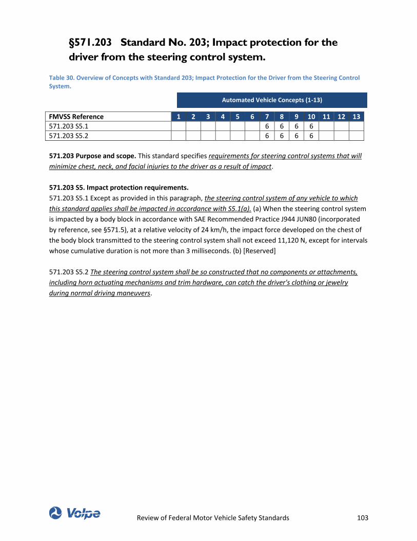
Review of Federal Motor Vehicle Safety Standards 103
§571.203 Standard No. 203; Impact protection for the
driver from the steering control system.
Table 30. Overview of Concepts with Standard 203; Impact Protection for the Driver from the Steering Control System.
FMVSS Reference 1 2 3 4 5 6 7 8 9 10 11 12 13
571.203 S5.1 6 6 6 6
571.203 S5.2 6 6 6 6
571.203 Purpose and scope. This standard specifies requirements for steering control systems that will
minimize chest, neck, and facial injuries to the driver as a result of impact.
571.203 S5. Impact protection requirements.
571.203 S5.1 Except as provided in this paragraph, the steering control system of any vehicle to which
this standard applies shall be impacted in accordance with S5.1(a). (a) When the steering control system
is impacted by a body block in accordance with SAE Recommended Practice J944 JUN80 (incorporated
by reference, see §571.5), at a relative velocity of 24 km/h, the impact force developed on the chest of
the body block transmitted to the steering control system shall not exceed 11,120 N, except for intervals
whose cumulative duration is not more than 3 milliseconds. (b) [Reserved]
571.203 S5.2 The steering control system shall be so constructed that no components or attachments,
including horn actuating mechanisms and trim hardware, can catch the driver's clothing or jewelry
during normal driving maneuvers.
Automated Vehicle Concepts (1-13)
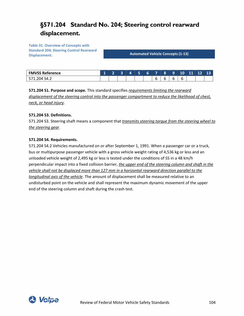
Review of Federal Motor Vehicle Safety Standards 104
§571.204 Standard No. 204; Steering control rearward
displacement.
Table 31. Overview of Concepts with Standard 204; Steering Control Rearward Displacement.
FMVSS Reference 1 2 3 4 5 6 7 8 9 10 11 12 13
571.204 S4.2 6 6 6 6
571.204 S1. Purpose and scope. This standard specifies requirements limiting the rearward
displacement of the steering control into the passenger compartment to reduce the likelihood of chest,
neck, or head injury.
571.204 S3. Definitions.
571.204 S3. Steering shaft means a component that transmits steering torque from the steering wheel to
the steering gear.
571.204 S4. Requirements.
571.204 S4.2 Vehicles manufactured on or after September 1, 1991. When a passenger car or a truck,
bus or multipurpose passenger vehicle with a gross vehicle weight rating of 4,536 kg or less and an
unloaded vehicle weight of 2,495 kg or less is tested under the conditions of S5 in a 48 km/h
perpendicular impact into a fixed collision barrier, the upper end of the steering column and shaft in the
vehicle shall not be displaced more than 127 mm in a horizontal rearward direction parallel to the
longitudinal axis of the vehicle. The amount of displacement shall be measured relative to an
undisturbed point on the vehicle and shall represent the maximum dynamic movement of the upper
end of the steering column and shaft during the crash test.
Automated Vehicle Concepts (1-13)
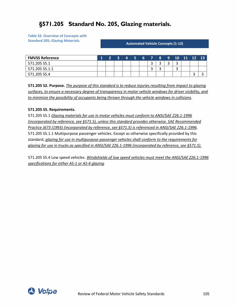
Review of Federal Motor Vehicle Safety Standards 105
§571.205 Standard No. 205, Glazing materials.
Table 32. Overview of Concepts with Standard 205; Glazing Materials.
FMVSS Reference 1 2 3 4 5 6 7 8 9 10 11 12 13
571.205 S5.1 3 3 3 3
571.205 S5.1.1 3 3 3
571.205 S5.4 3 3
571.205 S2. Purpose. The purpose of this standard is to reduce injuries resulting from impact to glazing
surfaces, to ensure a necessary degree of transparency in motor vehicle windows for driver visibility, and
to minimize the possibility of occupants being thrown through the vehicle windows in collisions.
571.205 S5. Requirements.
571.205 S5.1 Glazing materials for use in motor vehicles must conform to ANSI/SAE Z26.1-1996
(incorporated by reference, see §571.5), unless this standard provides otherwise. SAE Recommended
Practice J673 (1993) (incorporated by reference, see §571.5) is referenced in ANSI/SAE Z26.1-1996.
571.205 S5.1.1 Multipurpose passenger vehicles. Except as otherwise specifically provided by this
standard, glazing for use in multipurpose passenger vehicles shall conform to the requirements for
glazing for use in trucks as specified in ANSI/SAE Z26.1-1996 (incorporated by reference, see §571.5).
571.205 S5.4 Low speed vehicles. Windshields of low speed vehicles must meet the ANSI/SAE Z26.1-1996
specifications for either AS-1 or AS-4 glazing.
Automated Vehicle Concepts (1-13)

Review of Federal Motor Vehicle Safety Standards 106
§571.206 Standard No. 206; Door locks and door retention
components.
Table 33. Overview of Concepts with Standard 206; Door Locks and Door Retention Components.
FMVSS Reference 1 2 3 4 5 6 7 8 9 10 11 12 13
571.206 S3.Door closure warning system
1 1 1 1
571.206 S4 0
571.206 S4.1.2.3.(b) 1 1 1 1
571.206 S4.2.1.(b) 1 1 1 1
571.206 S4.3.1 2 2
571.206 S1. Scope and Purpose. This standard specifies requirements for vehicle door locks and door
retention components, including latches, hinges, and other supporting means, to minimize the likelihood
of occupants being ejected from a vehicle as a result of impact.
571.206 S3. Definitions.
571.206 S3. Door Closure Warning System is a system that will activate a visual signal when a door latch
system is not in its fully latched position and the vehicle ignition is activated.
571.206 S4. Requirements.
571.206 S4. The requirements apply to all side and back doors, that lead directly into a compartment
that contains one or more seating accommodations and the associated door components, except for
those on folding doors, roll-up doors, detachable doors, bus doors used only for emergency egress
purposes and labeled accordingly and on bus doors to accommodate a permanently attached
wheelchair lift system that when the device is in the retracted position, the lift platform retracts to a
vertical orientation parallel to and in close proximity with the interior surface of the lift door and in that
position, the platform completely covers the doorway opening, has fixed attachments to the vehicle and
provides a barricade to the doorway. The bus wheelchair lift door must be linked to an alarm system
consisting of either a flashing visible signal located in the driver's compartment or an alarm audible to
the driver that is activated when the door is not fully closed and the vehicle ignition is activated.
571.206 S4.1 Hinged doors.
571.206 S4.1.2 Door hinges.
571.206 S4.1.2.3 On side doors with rear mounted hinges that can be operated independently of other
doors, (a) The interior door handle shall be inoperative when the speed of the vehicle is greater than or
equal to 4 km/h, and (b) A door closure warning system shall be provided for those doors. The door
closure warning system shall be located where it can be clearly seen by the driver.
571.206 S4.2 Sliding Side Doors.
571.206 S4.2.1 Latch System. Each sliding door system shall be equipped with either: (a) At least one
Automated Vehicle Concepts (1-13)
Review of Federal Motor Vehicle Safety Standards 107
primary door latch system, or (b) A door latch system with a fully latched position and a door closure
warning system. The door closure warning system shall be located where it can be clearly seen by the
driver. Upon certification a manufacturer may not thereafter alter the designation of a primary latch.
Each manufacturer shall, upon request from the National Highway Traffic Safety Administration, provide
information regarding such designation.
571.206 S4.3 Door locks. Each door shall be equipped with at least one locking device which, when
engaged, shall prevent operation of the exterior door handle or other exterior latch release control and
which has an operating means and a lock release/engagement device located within the interior of the
vehicle.
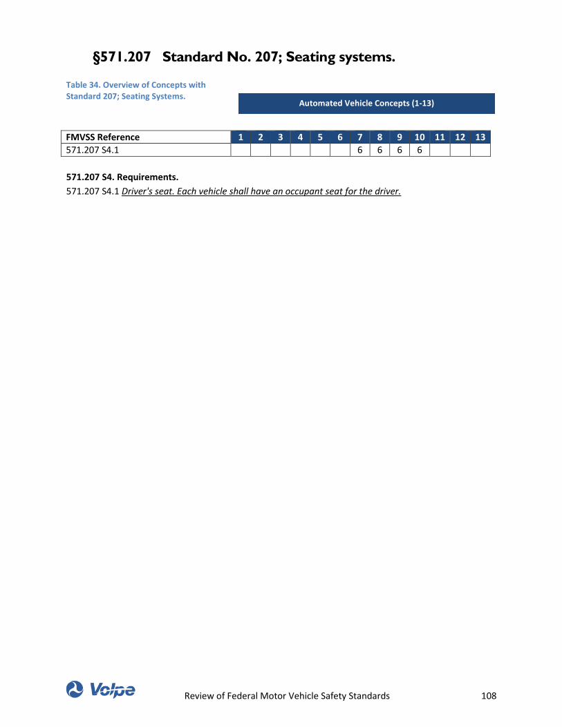
Review of Federal Motor Vehicle Safety Standards 108
§571.207 Standard No. 207; Seating systems.
Table 34. Overview of Concepts with Standard 207; Seating Systems.
FMVSS Reference 1 2 3 4 5 6 7 8 9 10 11 12 13
571.207 S4.1 6 6 6 6
571.207 S4. Requirements.
571.207 S4.1 Driver's seat. Each vehicle shall have an occupant seat for the driver.
Automated Vehicle Concepts (1-13)
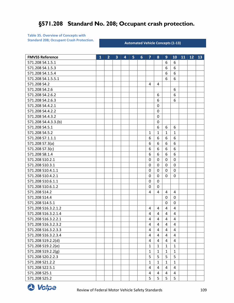
Review of Federal Motor Vehicle Safety Standards 109
§571.208 Standard No. 208; Occupant crash protection.
Table 35. Overview of Concepts with Standard 208; Occupant Crash Protection.
FMVSS Reference 1 2 3 4 5 6 7 8 9 10 11 12 13
571.208 S4.1.5.1 6 6
571.208 S4.1.5.3 6 6
571.208 S4.1.5.4 6 6
571.208 S4.1.5.5.1 6 6
571.208 S4.2 4 4
571.208 S4.2.6 6
571.208 S4.2.6.2 6 6
571.208 S4.2.6.3 6 6
571.208 S4.4.2.1 0
571.208 S4.4.2.2 0
571.208 S4.4.3.2 0
571.208 S4.4.3.3.(b) 0
571.208 S4.5.1 6 6 6
571.208 S4.5.2 1 1 1 1
571.208 S7.1.1.1 6 6 6 6
571.208 S7.3(a) 6 6 6 6
571.208 S7.3(c) 6 6 6 6
571.208 S8.1.4 6 6 6 6
571.208 S10.2.1 0 0 0 0
571.208 S10.3.1 0 0 0 0
571.208 S10.4.1.1 0 0 0 0
571.208 S10.4.2.1 0 0 0 0
571.208 S10.6.1.1 0 0
571.208 S10.6.1.2 0 0
571.208 S14.2 4 4 4 4
571.208 S14.4 0 0
571.208 S14.5.1 0 0
571.208 S16.3.2.1.2 4 4 4 4
571.208 S16.3.2.1.4 4 4 4 4
571.208 S16.3.2.2.1 4 4 4 4
571.208 S16.3.2.3.2 4 4 4 4
571.208 S16.3.2.3.3 4 4 4 4
571.208 S16.3.2.3.4 4 4 4 4
571.208 S19.2.2(d) 4 4 4 4
571.208 S19.2.2(e) 1 1 1 1
571.208 S19.2.2(g) 1 1 1 1
571.208 S20.2.2.3 5 5 5 5
571.208 S21.2.2 1 1 1 1
571.208 S22.5.1 4 4 4 4
571.208 S25.1 4 4 4 4
571.208 S25.2 5 5 5 5
Automated Vehicle Concepts (1-13)
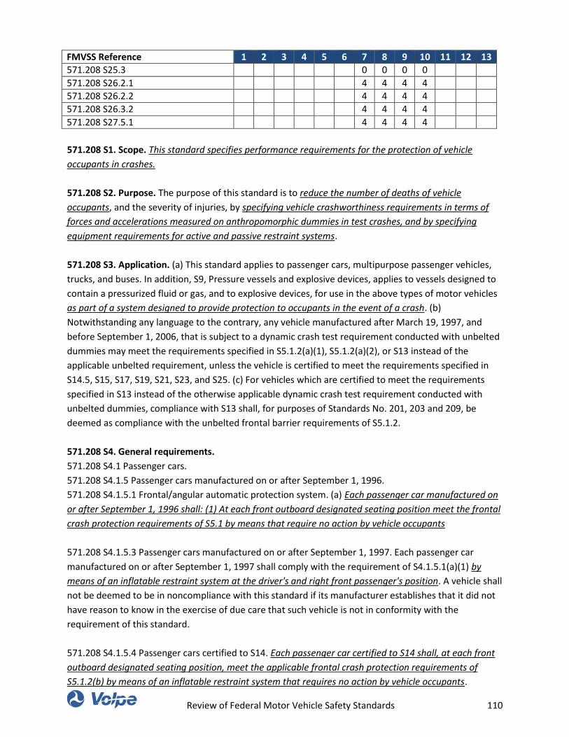
Review of Federal Motor Vehicle Safety Standards 110
FMVSS Reference 1 2 3 4 5 6 7 8 9 10 11 12 13
571.208 S25.3 0 0 0 0
571.208 S26.2.1 4 4 4 4
571.208 S26.2.2 4 4 4 4
571.208 S26.3.2 4 4 4 4
571.208 S27.5.1 4 4 4 4
571.208 S1. Scope. This standard specifies performance requirements for the protection of vehicle
occupants in crashes.
571.208 S2. Purpose. The purpose of this standard is to reduce the number of deaths of vehicle
occupants, and the severity of injuries, by specifying vehicle crashworthiness requirements in terms of
forces and accelerations measured on anthropomorphic dummies in test crashes, and by specifying
equipment requirements for active and passive restraint systems.
571.208 S3. Application. (a) This standard applies to passenger cars, multipurpose passenger vehicles,
trucks, and buses. In addition, S9, Pressure vessels and explosive devices, applies to vessels designed to
contain a pressurized fluid or gas, and to explosive devices, for use in the above types of motor vehicles
as part of a system designed to provide protection to occupants in the event of a crash. (b)
Notwithstanding any language to the contrary, any vehicle manufactured after March 19, 1997, and
before September 1, 2006, that is subject to a dynamic crash test requirement conducted with unbelted
dummies may meet the requirements specified in S5.1.2(a)(1), S5.1.2(a)(2), or S13 instead of the
applicable unbelted requirement, unless the vehicle is certified to meet the requirements specified in
S14.5, S15, S17, S19, S21, S23, and S25. (c) For vehicles which are certified to meet the requirements
specified in S13 instead of the otherwise applicable dynamic crash test requirement conducted with
unbelted dummies, compliance with S13 shall, for purposes of Standards No. 201, 203 and 209, be
deemed as compliance with the unbelted frontal barrier requirements of S5.1.2.
571.208 S4. General requirements.
571.208 S4.1 Passenger cars.
571.208 S4.1.5 Passenger cars manufactured on or after September 1, 1996.
571.208 S4.1.5.1 Frontal/angular automatic protection system. (a) Each passenger car manufactured on
or after September 1, 1996 shall: (1) At each front outboard designated seating position meet the frontal
crash protection requirements of S5.1 by means that require no action by vehicle occupants
571.208 S4.1.5.3 Passenger cars manufactured on or after September 1, 1997. Each passenger car
manufactured on or after September 1, 1997 shall comply with the requirement of S4.1.5.1(a)(1) by
means of an inflatable restraint system at the driver's and right front passenger's position. A vehicle shall
not be deemed to be in noncompliance with this standard if its manufacturer establishes that it did not
have reason to know in the exercise of due care that such vehicle is not in conformity with the
requirement of this standard.
571.208 S4.1.5.4 Passenger cars certified to S14. Each passenger car certified to S14 shall, at each front
outboard designated seating position, meet the applicable frontal crash protection requirements of
S5.1.2(b) by means of an inflatable restraint system that requires no action by vehicle occupants.
Review of Federal Motor Vehicle Safety Standards 111
571.208 S4.1.5.5 Passenger cars manufactured on or after September 1, 2007.
571.208 S4.1.5.5.1 Except as provided in S4.1.5.5.2, each passenger car shall have a Type 2 seat belt
assembly that conforms to Standard No. 209 and to S7.1 and S7.2 of this standard at each rear
designated seating position, except that side-facing designated seating positions shall have a Type 1 or
Type 2 seat belt assembly that conforms to Standard No. 209 and to S7.1 and S7.2 of this standard.
571.208 S4.2 Trucks and multipurpose passenger vehicles with a GVWR of 10,000 pounds or less. As
used in this section, vehicles manufactured for operation by persons with disabilities means vehicles
that incorporate a level change device (e.g., a wheelchair lift or a ramp) for onloading or offloading an
occupant in a wheelchair, an interior element of design intended to provide the vertical clearance
necessary to permit a person in a wheelchair to move between the lift or ramp and the driver's position
or to occupy that position, and either an adaptive control or special driver seating accommodation to
enable persons who have limited use of their arms or legs to operate a vehicle. For purposes of this
definition, special driver seating accommodations include a driver's seat easily removable with means
installed for that purpose or with simple tools, or a driver's seat with extended adjustment capability to
allow a person to easily transfer from a wheelchair to the driver's seat.
571.208 S4.2.6 Trucks, buses, and multipurpose passenger vehicles with a GVWR of 8,500 pounds or less
and an unloaded vehicle weight of 5,500 pounds or less manufactured on or after September 1, 1997.
Each truck, bus, and multipurpose passenger vehicle with a GVWR of 8,500 pounds or less and an
unloaded vehicle weight of 5,500 pounds or less, which is manufactured on or after September 1, 1997,
shall comply with the requirements of S4.1.5.1 of this standard (as specified for passenger cars), except
that walk-in van-type trucks and vehicles designed to be sold exclusively to the U.S. Postal Service may
meet the requirements of S4.2.1.1 or S4.2.1.2 of this standard instead of the requirements of S4.1.5.1.
571.208 S4.2.6.2 Trucks, buses, and multipurpose passenger vehicles with a GVWR of 8,500 pounds or
less and an unloaded vehicle weight of 5,500 pounds or less manufactured on or after September 1,
1998. Each truck, bus, or multipurpose vehicle with a GVWR of 8,500 pounds or less and an unloaded
vehicle weight of 5,500 pounds or less manufactured on or after September 1, 1998 shall comply with the
requirement of S4.1.5.1(a)(1) by means of an inflatable restraint system at the driver's and right front
passenger's position. A vehicle shall not be deemed to be in noncompliance with this standard if its
manufacturer establishes that it did not have reason to know in the exercise of due care that such
vehicle is not in conformity with the requirement of this standard.
571.208 S4.2.6.3 Trucks, buses, and multipurpose passenger vehicles certified to S14. Each truck, bus, or
multipurpose passenger vehicle with a GVWR of 3,855 kg (8,500 lb) or less and an unloaded vehicle
weight of 2,495 kg (5,500 lb) or less certified to S14 shall, at each front outboard designated seating
position, meet the applicable frontal crash protection requirements of S5.1.2(b) by means of an inflatable
restraint system that requires no action by vehicle occupants.
571.208 S4.4 Buses.
571.208 S4.4.2 Buses manufactured on or after September 1, 1990. Each bus manufactured on or after
September 1, 1990, shall meet the requirements of S4.4.2.1 or S4.4.2.2.
Review of Federal Motor Vehicle Safety Standards 112
571.208 S4.4.2.1 First option—complete passenger protection system—driver only. The vehicle shall
meet the crash protection requirements of S5, with respect to an anthropomorphic test dummy in the
driver's designated seating position, by means that require no action by vehicle occupants.
571.208 S4.4.2.2 Second option—belt system—driver only. The vehicle shall, at the driver's designated
seating position, have either a Type 1 or a Type 2 seat belt assembly that conforms to §571.209 of this
part and S7.2 of this Standard. A Type 1 belt assembly or the pelvic portion of a dual retractor Type 2 belt
assembly installed at the driver's seating position shall include either an emergency locking retractor or
an automatic locking retractor. If a seat belt assembly installed at the driver's seating position includes
an automatic locking retractor for the lap belt or the lap belt portion, that seat belt assembly shall
comply with the following: (a) An automatic locking retractor used at a driver's seating position that has
some type of suspension system for the seat shall be attached to the seat structure that moves as the
suspension system functions. (b) The lap belt or lap belt portion of a seat belt assembly equipped with
an automatic locking retractor that is installed at the driver's seating position must allow at least 3⁄4
inch, but less than 3 inches, of webbing movement before retracting webbing to the next locking
position.
571.208 S4.4.3 Buses manufactured on or after September 1, 1991.
571.208 S4.4.3.2 Except as provided in S4.4.3.2.2 and S4.4.3.2.3, each bus with a gross vehicle weight
rating of 10,000 pounds or less, except a school bus, shall be equipped with an integral Type 2 seat belt
assembly at the driver's designated seating position and at the front and every rear forward-facing
outboard designated seating position, and with a Type 1 or Type 2 seat belt assembly at all other
designated seating positions. Type 2 seat belt assemblies installed in compliance with this requirement
shall comply with Standard No. 209 (49 CFR 571.209) and with S7.1 and S7.2 of this standard. If a Type 2
seat belt assembly installed in compliance with this requirement incorporates any webbing tension-
relieving device, the vehicle owner's manual shall include the information specified in S7.4.2(b) of this
standard for the tension relieving device, and the vehicle shall comply with S7.4.2(c) of this standard.
571.208 S4.4.3.3 School buses with a gross vehicle weight rating of 4,536 kg (10,000 pounds) or less. (a)
Each school bus with a gross vehicle weight rating of 4,536 kg (10,000 pounds) or less manufactured
before October 21, 2011 must be equipped with an integral Type 2 seat belt assembly at the driver's
designated seating position and at the right front passenger's designated seating position (if any), and
with a Type 1 or Type 2 seat belt assembly at all other seating positions. Type 2 seat belt assemblies
installed in compliance with this requirement must comply with Standard No. 209 (49 CFR 571.209) and
with S7.1 and S7.2 of this standard. The lap belt portion of a Type 2 seat belt assembly installed at the
driver's designated seating position and at the right front passenger's designated seating position (if
any) must meet the requirements specified in S4.4.3.3(c). (b) Each school bus with a gross vehicle weight
rating of 4,536 kg (10,000 pounds) or less manufactured on or after October 21, 2011 must be equipped
with an integral Type 2 seat belt assembly at all seating positions. The seat belt assembly at the driver's
designated seating position and at the right front passenger's designated seating position (if any) shall
comply with Standard No. 209 (49 CFR 571.209) and with S7.1 and S7.2 of this standard. The lap belt
portion of a Type 2 seat belt assembly installed at the driver's designated seating position and at the
right front passenger's designated seating position (if any) shall meet the requirements specified in
S4.4.3.3 (c). Type 2 seat belt assemblies installed on the rear seats of school buses must meet the
requirements of S7.1.1.5, S7.1.5 and S7.2 of this standard. (c) The lap belt portion of a Type 2 seat belt
Review of Federal Motor Vehicle Safety Standards 113
assembly installed at the driver's designated seating position and at the right front passenger's
designated seating position (if any) shall include either an emergency locking retractor or an automatic
locking retractor, which retractor shall not retract webbing to the next locking position until at least 3⁄4
inch of webbing has moved into the retractor. In determining whether an automatic locking retractor
complies with this requirement, the webbing is extended to 75 percent of its length and the retractor is
locked after the initial adjustment. If a Type 2 seat belt assembly installed in compliance with this
requirement incorporates any webbing tension-relieving device, the vehicle owner's manual shall
include the information specified in S7.4.2(b) of this standard for the tension-relieving device, and the
vehicle shall comply with S7.4.2(c) of this standard.
571.208 S4.5 Other general requirements.
571.208 S4.5.1 Labeling and owner's manual information.
571.208 S4.5.2 Readiness indicator. An occupant protection system that deploys in the event of a crash
shall have a monitoring system with a readiness indicator. The indicator shall monitor its own readiness
and shall be clearly visible from the driver's designated seating position. If the vehicle is equipped with a
single readiness indicator for both a driver and passenger air bag, and if the vehicle is equipped with an
on-off switch permitted by S4.5.4 of this standard, the readiness indicator shall monitor the readiness of
the driver air bag when the passenger air bag has been deactivated by means of the on-off switch, and
shall not illuminate solely because the passenger air bag has been deactivated by the manual on-off
switch. A list of the elements of the system being monitored by the indicator shall be included with the
information furnished in accordance with S4.5.1 but need not be included on the label.
571.208 S7. Seat belt assembly requirements.
571.208 S7.1 Adjustment.
571.208 S7.1.1 Except as specified in S7.1.1.1 and S7.1.1.2, the lap belt of any seat belt assembly
furnished in accordance with S4.1.2 shall adjust by means of any emergency-locking or automatic-
locking retractor that conforms to §571.209 to fit persons whose dimensions range from those of a 50th
percentile 6-year-old child to those of a 95th percentile adult male and the upper torso restraint shall
adjust by means of an emergency-locking retractor or a manual adjusting device that conforms to
§571.209 to fit persons whose dimensions range from those of a 5th percentile adult female to those of
a 95th percentile adult male, with the seat in any position, the seat back in the manufacturer's nominal
design riding position, and any adjustable anchorages adjusted to the manufacturer's nominal design
position for a 50th percentile adult male occupant. However, an upper torso restraint furnished in
accordance with S4.1.2.3.1(a) shall adjust by means of an emergency-locking retractor that conforms to
§571.209.
571.208 S7.1.1.1 A seat belt assembly installed at the driver's seating position shall adjust to fit persons
whose dimensions range from those of a 5th-percentile adult female to those of a 95th-percentile adult
male.
571.208 S7.3 (a) A seat belt assembly provided at the driver's seating position shall be equipped with a
warning system that, at the option of the manufacturer, either— (1) Activates a continuous or
intermittent audible signal for a period of not less than 4 seconds and not more than 8 seconds and that
activates a continuous or flashing warning light visible to the driver displaying the identifying symbol for
Review of Federal Motor Vehicle Safety Standards 114
the seat belt telltale shown in Table 2 of FMVSS 101 or, at the option of the manufacturer if permitted by
FMVSS 101, displaying the words “Fasten Seat Belts” or “Fasten Belts”, for not less than 60 seconds
(beginning when the vehicle ignition switch is moved to the “on” or the “start” position) when condition
(b) exists simultaneously with condition (c), or that (2) Activates, for a period of not less than 4 seconds
and not more than 8 seconds (beginning when the vehicle ignition switch is moved to the “on” or the
“start” position), a continuous or flashing warning light visible to the driver, displaying the identifying
symbol of the seat belt telltale shown in Table 2 of FMVSS 101 or, at the option of the manufacturer if
permitted by FMVSS 101, displaying the words “Fasten Seat Belts” or “Fasten Belts”, when condition (b)
exists, and a continuous or intermittent audible signal when condition (b) exists simultaneously with
condition (c). (b) The vehicle's ignition switch is moved to the “on” position or to the “start” position. (c)
The driver's lap belt is not in use, as determined, at the option of the manufacturer, either by the belt
latch mechanism not being fastened, or by the belt not being extended at least 4 inches from its stowed
position.
571.208 S8. Test Conditions.
571.208 S8.1 General Conditions.
571.208 S8.1.4 Adjustable steering controls are adjusted so that the steering wheel hub is at the
geometric center of the locus it describes when it is moved through its full range of driving positions.
571.208 S10. Test dummy positioning procedures.
571.208 S10.2 Upper Arms.
571.208 S10.2.1 The driver's upper arms shall be adjacent to the torso with the centerlines as close to a
vertical plane as possible.
571.208 S10.3 Hands.
571.208 S10.3.1 The palms of the drivers test dummy shall be in contact with the outer part of the
steering wheel rim at the rim's horizontal centerline. The thumbs shall be over the steering wheel rim and
shall be lightly taped to the steering wheel rim so that if the hand of the test dummy is pushed upward
by a force of not less than 2 pounds and not more than 5 pounds, the tape shall release the hand from
the steering wheel rim.
571.208 S10.4 Torso.
571.208 S10.4.1 Upper Torso.
571.208 S10.4.1.1 In vehicles equipped with bench seats, the upper torso of the driver and passenger
test dummies shall rest against the seat back. The midsagittal plane of the driver dummy shall be vertical
and parallel to the vehicle's longitudinal centerline, and pass through the center of the steering wheel
rim. The midsagittal plane of the passenger dummy shall be vertical and parallel to the vehicle's
longitudinal centerline and the same distance from the vehicle's longitudinal centerline as the
midsagittal plane of the driver dummy.
571.208 S10.4.2 Lower Torso.
571.208 S10.4.2.1 H-point. The H-points of the driver and passenger test dummies shall coincide within
1⁄2 inch in the vertical dimension and 1⁄2 inch in the horizontal dimension of a point 1⁄4 inch below the
position of the H-point determined by using the equipment and procedures specified in SAE Standard
J826-1980 (incorporated by reference, see §571.5), except that the length of the lower leg and thigh
Review of Federal Motor Vehicle Safety Standards 115
segments of the H-point machine shall be adjusted to 16.3 and 15.8 inches, respectively, instead of the
50th percentile values specified in Table 1 of SAE Standard J826-1980.
571.208 S10.5 Legs. The upper legs of the driver and passenger test dummies shall rest against the seat
cushion to the extent permitted by placement of the feet. The initial distance between the outboard
knee clevis flange surfaces shall be 10.6 inches. To the extent practicable, the left leg of the driver
dummy and both legs of the passenger dummy shall be in vertical longitudinal planes. To the extent
practicable, the right leg of the driver dummy shall be in a vertical plane. Final adjustment to
accommodate the placement of feet in accordance with S10.6 for various passenger compartment
configurations is permitted.
571.208 S10.6 Feet.
571.208 S10.6.1 Driver’s position.
571.208 S10.6.1.1 If the vehicle has an adjustable accelerator pedal, adjust it to the full forward position.
Rest the right foot of the test dummy on the undepressed accelerator pedal with the rearmost point of
the heel on the floor pan in the plane of the pedal. If the foot cannot be placed on the accelerator pedal,
set it initially perpendicular to the lower leg and then place it as far forward as possible in the direction
of the pedal centerline with the rearmost point of the heel resting on the floor pan. If the vehicle has an
adjustable accelerator pedal and the right foot is not touching the accelerator pedal when positioned as
above, move the pedal rearward until it touches the right foot. If the accelerator pedal still does not
touch the foot in the full rearward position, leave the pedal in that position.
571.208 S10.6.1.2 Place the left foot on the toeboard with the rearmost point of the heel resting on the
floor pan as close as possible to the point of intersection of the planes described by the toeboard and
the floor pan and not on the wheelwell projection. If the foot cannot be positioned on the toeboard, set
it initially perpendicular to the lower leg and place it as far forward as possible with the heel resting on
the floor pan. If necessary to avoid contact with the vehicle's brake or clutch pedal, rotate the test
dummy's left foot about the lower leg. If there is still pedal interference, rotate the left leg outboard
about the hip the minimum distance necessary to avoid the pedal interference. For vehicles with a foot
rest that does not elevate the left foot above the level of the right foot, place the left foot on the foot rest
so that the upper and lower leg centerlines fall in a vertical plane.
571.208 S14 Advanced air bag requirements for passenger cars and for trucks, buses, and
multipurpose passenger vehicles with a GVWR of 3,855 kg (8500 pounds) or less and an unloaded
vehicle weight of 2,495 kg (5500 pounds) or less, except for walk-in van-type trucks or vehicles
designed to be sold exclusively to the U.S. Postal Service.
571.208 S14.2 Vehicles manufactured on or after September 1, 2006. Each vehicle shall meet the
requirements specified in S14.5.1(a), S14.5.2, S15.1, S15.2, S17, S19, S21, S23, and S25 (in addition to
the other requirements specified in this standard).
571.208 S14.4 Vehicles manufactured on or after September 1, 2010. Each vehicle shall meet the
requirements specified in S14.5.1(b), S14.5.2, S15.1, S15.2, S17, S19, S21, S23, and S25 (in addition to
the other requirements specified in this standard).
Review of Federal Motor Vehicle Safety Standards 116
571.208 S14.5 Barrier test requirements using 50th percentile adult male dummies.
571.208 S14.5.1 Rigid barrier belted test. (a) Each vehicle that is certified as complying with S14.1 or
S14.2 shall, at each front outboard designated seating position, meet the injury criteria specified in S6.1,
S6.2(b), S6.3, S6.4(b), S6.5, and S6.6 when tested under S5.1.1(b)(1). (b) Each vehicle that is certified as
complying with S14.3 or S14.4 shall, at each front outboard designated seating position, meet the injury
criteria specified in S6.1, S6.2(b), S6.3, S6.4(b), S6.5, and S6.6 when tested under S5.1.1(b)(2).
571.208 S16. Test procedures for rigid barrier test requirements using 5th percentile adult female
dummies.
571.208 S16.3 Dummy seating positioning procedures
571.208 S16.3.2 Driver dummy positioning.
571.208 S16.3.2.1 Driver torso/head/seat back angle positioning.
571.208 S16.3.2.1.2 Fully recline the seat back, if adjustable. Install the dummy into the driver's seat,
such that when the legs are positioned 120 degrees to the thighs, the calves of the legs are not touching
the seat cushion.
571.208 S16.3.2.1.4 Bench seats. Position the midsagittal plane of the dummy vertical and parallel to the
vehicle's longitudinal centerline and aligned within ±10 mm (±0.4 in) of the center of the steering wheel
rim.
571.208 S16.3.2.2 Driver foot positioning.
571.208 S16.3.2.2.1 If the vehicle has an adjustable accelerator pedal, adjust it to the full forward
position. If the heel of the right foot can contact the floor pan, follow the positioning procedure in (a). If
not, follow the positioning procedure in (b). (a) Rest the right foot of the test dummy on the
undepressed accelerator pedal with the rearmost point of the heel on the floor pan in the plane of the
pedal. If the foot cannot be placed on the accelerator pedal, set it initially perpendicular to the leg and
then place it as far forward as possible in the direction of the pedal centerline with the rearmost point of
the heel resting on the floor pan. If the vehicle has an adjustable accelerator pedal and the right foot is
not touching the accelerator pedal when positioned as above, move the pedal rearward until it touches
the right foot. If the accelerator pedal in the full rearward position still does not touch the foot, leave
the pedal in that position. Extend the foot and lower leg by decreasing the knee flexion angle until any
part of the foot contacts the undepressed accelerator pedal. If the foot does not contact the pedal,
place the highest part of the foot at the same height as the highest part of the pedal. (b) Extend the foot
and lower leg by decreasing the knee flexion angle until any part of the foot contacts the undepressed
accelerator pedal or the highest part of the foot is at the same height as the highest part of the pedal. If
the vehicle has an adjustable accelerator pedal and the right foot is not touching the accelerator pedal
when positioned as above, move the pedal rearward until it touches the right foot.
571.208 S16.3.2.3 Driver arm/hand positioning.
571.208 S16.3.2.3.2 Place the palms of the dummy in contact with the outer part of the steering wheel
rim at its horizontal centerline with the thumbs over the steering wheel rim.
571.208 S16.3.2.3.3 If it is not possible to position the thumbs inside the steering wheel rim at its
horizontal centerline, then position them above and as close to the horizontal centerline of the steering
wheel rim as possible.
Review of Federal Motor Vehicle Safety Standards 117
571.208 S16.3.2.3.4 Lightly tape the hands to the steering wheel rim so that if the hand of the test
dummy is pushed upward by a force of not less than 9 N (2 lb) and not more than 22 N (5 lb), the tape
releases the hand from the steering wheel rim.
571.208 S19 Requirements to provide protection for infants in rear facing and convertible child
restraints and car beds.
571.208 S19.2 Option 1—Automatic suppression feature. Each vehicle shall meet the requirements
specified in S19.2.1 through S19.2.3.
571.208 S19.2.2 The vehicle shall be equipped with at least one telltale which emits light whenever the
passenger air bag system is deactivated and does not emit light whenever the passenger air bag system
is activated, except that the telltale(s) need not illuminate when the passenger seat is unoccupied. Each
telltale: (a) Shall emit yellow light; (b) Shall have the identifying words “PASSENGER AIR BAG OFF” or
“PASS AIR BAG OFF” on the telltale or within 25 mm (1.0 in) of the telltale; and (c) Shall not be combined
with the readiness indicator required by S4.5.2 of this standard. (d) Shall be located within the interior of
the vehicle and forward of and above the design H-point of both the driver's and the right front
passenger's seat in their forwardmost seating positions and shall not be located on or adjacent to a
surface that can be used for temporary or permanent storage of objects that could obscure the telltale
from either the driver's or right front passenger's view, or located where the telltale would be obscured
from the driver's view if a rear-facing child restraint listed in appendix A or A-1, as appropriate, is
installed in the right front passenger's seat. (e) Shall be visible and recognizable to a driver and right
front passenger during night and day when the occupants have adapted to the ambient light roadway
conditions. (f) Telltales need not be visible or recognizable when not activated. (g) Means shall be
provided for making telltales visible and recognizable to the driver and right front passenger under all
driving conditions. The means for providing the required visibility may be adjustable manually or
automatically, except that the telltales may not be adjustable under any driving conditions to a level that
they become invisible or not recognizable to the driver and right front passenger. (h) The telltale must
not emit light except when the passenger air bag is turned off or during a bulb check upon vehicle
starting.
571.208 S20 Test procedure for S19.
571.208 S20.2 Static tests of automatic suppression feature which shall result in deactivation of the
passenger air bag. Each vehicle that is certified as complying with S19.2 shall meet the following test
requirements.
571.208 S20.2.2 Unbelted rear facing and convertible child restraints.
571.208 S20.2.2.3 For bucket seats, “Plane B” refers to a vertical plane parallel to the vehicle longitudinal
centerline through the longitudinal centerline of the front outboard passenger vehicle seat cushion. For
bench seats, “Plane B” refers to a vertical plane through the front outboard passenger seat parallel to
the vehicle longitudinal centerline the same distance from the longitudinal centerline of the vehicle as
the center of the steering wheel.
571.208 S21 Requirements using 3-year-old child dummies.
571.208 S21.2 Option 1 – Automatic suppression feature. Each vehicle shall meet the requirements
specified in S21.2.1 through S21.2.3.
571.208 S21.2.2 The vehicle shall be equipped with a telltale light meeting the requirements specified in
Review of Federal Motor Vehicle Safety Standards 118
S19.2.2.
571.208 S22 Test procedure for S21.
571.208 S22.5 Test procedure for determining stages of air bag systems subject to low risk deployment
(low speed crashes) test requirement.
571.208 S22.5.1 The test described in S22.5.2 shall be conducted with an unbelted 50th percentile adult
male test dummy in the driver seating position according to S8 as it applies to that seating position and
an unbelted 5th percentile adult female test dummy either in the front outboard passenger vehicle
seating position according to S16 as it applies to that seating position or at any fore-aft seat position on
the passenger side.
571.208 S25 Requirements using an out-of-position 5th percentile adult female dummy at the driver
position.
571.208 S25.1 Each vehicle certified as complying with S14 shall, at the option of the manufacturer,
meet the requirements specified in S25.2 or S25.3 under the test procedures specified in S26 or S28, as
appropriate.
571.208 S25.2 Option 1—Dynamic automatic suppression system that suppresses the air bag when the driver is out of position. (This option is available under the conditions set forth in S27.1.) The vehicle shall be equipped with a dynamic automatic suppression system for the driver air bag which meets the requirements specified in S27. 571.208 S25.3 Option 2—Low risk deployment. Each vehicle shall meet the injury criteria specified by S15.3 of this standard, except as modified in S25.4, when the driver air bag is statically deployed in accordance with both of the low risk deployment test procedures specified in S26. 571.208 S26 Procedure for low risk deployment test of driver air bag. 571.208 S26.2 Driver position 1 (chin on module). 571.208 S26.2.1 Adjust the steering controls so that the steering wheel hub is at the geometric center of the locus it describes when it is moved through its full range of driving positions. If there is no setting at the geometric center, position it one setting lower than the geometric center. Set the rotation of the steering wheel so that the vehicle wheels are pointed straight ahead. 571.208 S26.2.2 Mark a point on the steering wheel cover that is longitudinally and transversely, as measured along the surface of the steering wheel cover, within ±6 mm (±0.2 in) of the point that is defined by the intersection of the steering wheel cover and a line between the volumetric center of the smallest volume that can encompass the folded undeployed air bag and the volumetric center of the static fully inflated air bag. Locate the vertical plane parallel to the vehicle longitudinal centerline through the point located on the steering wheel cover. This is referred to as “Plane E.” 571.208 S26.3 Driver position 2 (chin on rim). 571.208 S26.3.2 Adjust the steering controls so that the steering wheel hub is at the geometric center of the locus it describes when it is moved through its full range of driving positions. If there is no setting at the geometric center, position it one setting lower than the geometric center. Set the rotation of the steering wheel so that the vehicle wheels are pointed straight ahead.

Review of Federal Motor Vehicle Safety Standards 119
571.208 S27 Option for dynamic automatic suppression system that suppresses the air bag when an occupant is out-of-position. 571.208 S27.5 Static test requirement (low risk deployment for occupants outside the ASZ). 571.208 S27.5.1 Driver (49 CFR part 572 subpart O 5th percentile female dummy). Each vehicle shall meet the injury criteria specified in S15.3 of this standard when the driver air bag is deployed in accordance with the procedures specified in S28.1. 571.208 S28 Test procedure for S27 of this standard. [Reserved] 571.208 S28.1 Driver suppression zone verification test (49 CFR part 572 Subpart O 5th percentile female dummy).[Reserved] 571.208 S28.3 Driver dynamic test procedure for DASS requirements. [Reserved]
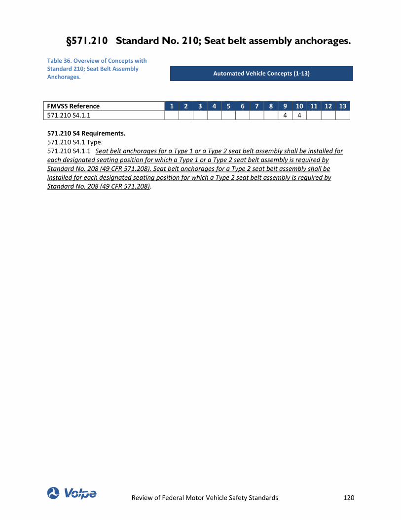
Review of Federal Motor Vehicle Safety Standards 120
§571.210 Standard No. 210; Seat belt assembly anchorages.
Table 36. Overview of Concepts with Standard 210; Seat Belt Assembly Anchorages.
FMVSS Reference 1 2 3 4 5 6 7 8 9 10 11 12 13
571.210 S4.1.1 4 4
571.210 S4 Requirements. 571.210 S4.1 Type. 571.210 S4.1.1 Seat belt anchorages for a Type 1 or a Type 2 seat belt assembly shall be installed for each designated seating position for which a Type 1 or a Type 2 seat belt assembly is required by Standard No. 208 (49 CFR 571.208). Seat belt anchorages for a Type 2 seat belt assembly shall be installed for each designated seating position for which a Type 2 seat belt assembly is required by Standard No. 208 (49 CFR 571.208).
Automated Vehicle Concepts (1-13)
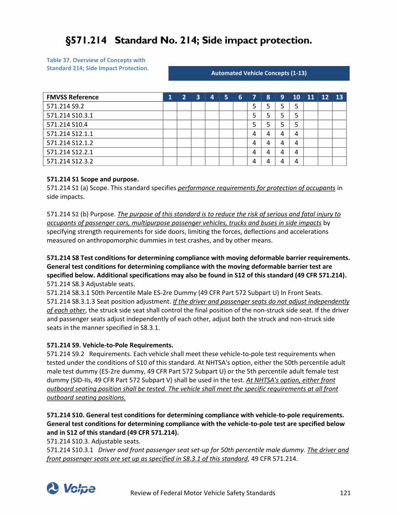
Review of Federal Motor Vehicle Safety Standards 121
§571.214 Standard No. 214; Side impact protection.
Table 37. Overview of Concepts with Standard 214; Side Impact Protection.
FMVSS Reference 1 2 3 4 5 6 7 8 9 10 11 12 13
571.214 S9.2 5 5 5 5
571.214 S10.3.1 5 5 5 5
571.214 S10.4 5 5 5 5
571.214 S12.1.1 4 4 4 4
571.214 S12.1.2 4 4 4 4
571.214 S12.2.1 4 4 4 4
571.214 S12.3.2 4 4 4 4
571.214 S1 Scope and purpose. 571.214 S1 (a) Scope. This standard specifies performance requirements for protection of occupants in side impacts. 571.214 S1 (b) Purpose. The purpose of this standard is to reduce the risk of serious and fatal injury to occupants of passenger cars, multipurpose passenger vehicles, trucks and buses in side impacts by specifying strength requirements for side doors, limiting the forces, deflections and accelerations measured on anthropomorphic dummies in test crashes, and by other means. 571.214 S8 Test conditions for determining compliance with moving deformable barrier requirements. General test conditions for determining compliance with the moving deformable barrier test are specified below. Additional specifications may also be found in S12 of this standard (49 CFR 571.214). 571.214 S8.3 Adjustable seats. 571.214 S8.3.1 50th Percentile Male ES-2re Dummy (49 CFR Part 572 Subpart U) In Front Seats. 571.214 S8.3.1.3 Seat position adjustment. If the driver and passenger seats do not adjust independently of each other, the struck side seat shall control the final position of the non-struck side seat. If the driver and passenger seats adjust independently of each other, adjust both the struck and non-struck side seats in the manner specified in S8.3.1. 571.214 S9. Vehicle-to-Pole Requirements. 571.214 S9.2 Requirements. Each vehicle shall meet these vehicle-to-pole test requirements when tested under the conditions of S10 of this standard. At NHTSA's option, either the 50th percentile adult male test dummy (ES-2re dummy, 49 CFR Part 572 Subpart U) or the 5th percentile adult female test dummy (SID-IIs, 49 CFR Part 572 Subpart V) shall be used in the test. At NHTSA's option, either front outboard seating position shall be tested. The vehicle shall meet the specific requirements at all front outboard seating positions. 571.214 S10. General test conditions for determining compliance with vehicle-to-pole requirements. General test conditions for determining compliance with the vehicle-to-pole test are specified below and in S12 of this standard (49 CFR 571.214). 571.214 S10.3. Adjustable seats. 571.214 S10.3.1 Driver and front passenger seat set-up for 50th percentile male dummy. The driver and front passenger seats are set up as specified in S8.3.1 of this standard, 49 CFR 571.214.
Automated Vehicle Concepts (1-13)
Review of Federal Motor Vehicle Safety Standards 122
571.214 S10.4 Positioning dummies for the vehicle-to-pole test. (a) 50th percentile male test dummy (49 CFR Part 572 Subpart U ES-2re dummy). The 50th percentile male test dummy is positioned in the front outboard seating position on the struck side of the vehicle in accordance with the provisions of S12.2 of this standard, 49 CFR 571.214. (b) 5th percentile female test dummy (49 CFR Part 572 Subpart V SID-IIs dummy). The 5th percentile female test dummy is positioned in the front outboard seating positions on the struck side of the vehicle in accordance with the provisions of S12.3 of this standard, 49 CFR 571.214 571.214 S12 Positioning procedures for the anthropomorphic test dummies. 571.214 S12.1 50th percentile male test dummy—49 CFR part 572 subpart F (SID). 571.214 S12.1.1 Positioning a Part 572 Subpart F (SID) dummy in the driver position. (a) Torso. Hold the dummy's head in place and push laterally on the non-impacted side of the upper torso in a single stroke with a force of 66.7-89.0 N (15-20 lb) towards the impacted side. (1) For a bench seat. The upper torso of the test dummy rests against the seat back. The midsagittal plane of the test dummy is vertical and parallel to the vehicle's longitudinal centerline, and passes through the center of the steering wheel. (2) For a bucket seat. The upper torso of the test dummy rests against the seat back. The midsagittal plane of the test dummy is vertical and parallel to the vehicle's longitudinal centerline, and coincides with the longitudinal centerline of the bucket seat. (b) Pelvis. (1) H-point. The H-points of each test dummy coincide within 12.7 mm ( 1⁄2 inch) in the vertical dimension and 12.7 mm ( 1⁄2 inch) in the horizontal dimension of a point that is located 6.4 mm ( 1⁄4 inch) below the position of the H-point determined by using the equipment for the 50th percentile and procedures specified in SAE Standard J826-1980 (incorporated by reference, see §571.5), except that Table 1 of SAE Standard J826-1980 is not applicable. The length of the lower leg and thigh segments of the H-point machine are adjusted to 414 and 401 mm (16.3 and 15.8 inches), respectively. (2) Pelvic angle. As determined using the pelvic angle gauge (GM drawing 78051-532 incorporated by reference in part 572, Subpart E of this chapter) which is inserted into the H-point gauging hole of the dummy, the angle of the plane of the surface on the lumbar-pelvic adaptor on which the lumbar spine attaches is 23 to 25 degrees from the horizontal, sloping upward toward the front of the vehicle. (3) Legs. The upper legs of each test dummy rest against the seat cushion to the extent permitted by placement of the feet. The left knee of the dummy is positioned such that the distance from the outer surface of the knee pivot bolt to the dummy's midsagittal plane is 152.4 mm (6.0 inches). To the extent practicable, the left leg of the test dummy is in a vertical longitudinal plane. (4) Feet. The right foot of the test dummy rests on the undepressed accelerator with the heel resting as far forward as possible on the floorpan. The left foot is set perpendicular to the lower leg with the heel resting on the floorpan in the same lateral line as the right heel. 571.214 S12.1.2 Positioning a Part 572 Subpart F (SID) dummy in the front outboard seating position. (a) Torso. Hold the dummy's head in place and push laterally on the non-impacted side of the upper torso in a single stroke with a force of 66.7-89.0 N (15-20 lb) towards the impacted side. (1) For a bench seat. The upper torso of the test dummy rests against the seat back. The midsagittal plane of the test dummy is vertical and parallel to the vehicle's longitudinal centerline, and the same distance from the vehicle's longitudinal centerline as would be the midsagittal plane of a test dummy positioned in the driver position under S12.1.1(a)(1). (2) For a bucket seat. The upper torso of the test dummy rests against the seat back. The midsagittal plane of the test dummy is vertical and parallel to the vehicle's longitudinal centerline, and coincides with the longitudinal centerline of the bucket seat. (b) Pelvis. (1) H-point. The H-points of each test dummy coincide within 12.7 mm ( 1⁄2 inch) in the vertical dimension and 12.7 mm ( 1⁄2 inch) in the horizontal dimension of a point that is located 6.4 mm ( 1⁄4 inch) below the position of the H-point determined by using the equipment for the 50th percentile and procedures specified in SAE Standard J826-1980 (incorporated by reference, see §571.5), except that Table 1 of SAE J826-1980 is not applicable. The length of the lower leg and thigh segments of the H-point machine are adjusted to 414 and 401 mm (16.3 and 15.8 inches), respectively. (2) Pelvic angle. As determined using the pelvic angle gauge (GM drawing 78051-532 incorporated by reference in part 572, Subpart E of this chapter) which is
Review of Federal Motor Vehicle Safety Standards 123
inserted into the H-point gauging hole of the dummy, the angle of the plane of the surface on the lumbar-pelvic adaptor on which the lumbar spine attaches is 23 to 25 degrees from the horizontal, sloping upward toward the front of the vehicle. (c) Legs. The upper legs of each test dummy rest against the seat cushion to the extent permitted by placement of the feet. The initial distance between the outboard knee clevis flange surfaces is 292 mm (11.5 inches). To the extent practicable, both legs of the test dummies in outboard passenger positions are in vertical longitudinal planes. Final adjustment to accommodate placement of feet in accordance with S12.1.2(d) for various passenger compartment configurations is permitted. (d) Feet. The feet of the test dummy are placed on the vehicle's toeboard with the heels resting on the floorpan as close as possible to the intersection of the toeboard and floorpan. If the feet cannot be placed flat on the toeboard, they are set perpendicular to the lower legs and placed as far forward as possible so that the heels rest on the floorpan. 571.214.12.2 Positioning an ES-2re dummy in all seating positions. 571.214.12.2.1 Positioning an ES-2re dummy in all seating positions. Position a correctly configured ES-2re test dummy, conforming to the applicable requirements of part 572 of this chapter, in the front outboard seating position on the side of the test vehicle to be struck by the moving deformable barrier or pole. Restrain the test dummy using all available belt systems in the seating positions where the belt restraints are provided. Place any adjustable anchorages at the manufacturer's nominal design position for a 50th percentile adult male occupant. Retract any folding armrest. (a) Upper torso. (1) The plane of symmetry of the dummy coincides with the vertical median plane of the specified seating position. (2) Bend the upper torso forward and then lay it back against the seat back. Set the shoulders of the dummy fully rearward. (b) Pelvis. Position the pelvis of the dummy according to the following: (1) Position the pelvis of the dummy such that a lateral line passing through the dummy H-points is perpendicular to the longitudinal center plane of the seat. The line through the dummy H-points is horizontal with a maximum inclination of ±2 degrees. The dummy may be equipped with tilt sensors in the thorax and the pelvis. These instruments can help to obtain the desired position. (2) The correct position of the dummy pelvis may be checked relative to the H-point of the H-point Manikin by using the M3 holes in the H-point back plates at each side of the ES-2re pelvis. Position the dummy such that the M3 holes are located within a circle of radius 10 mm (0.39 in.) around the H-point of the H-point Manikin. (c) Arms. For the driver seating position and for the front outboard passenger seating position, place the dummy's upper arms such that the angle between the projection of the arm centerline on the mid-sagittal plane of the dummy and the torso reference line is 40° ±5°. The torso reference line is defined as the thoracic spine centerline. The shoulder-arm joint allows for discrete arm positions at 0, 40, and 90 degree settings forward of the spine. (d) Legs and Feet. Position the legs and feet of the dummy according to the following: (1) For the driver's seating position, without inducing pelvis or torso movement, place the right foot of the dummy on the un-pressed accelerator pedal with the heel resting as far forward as possible on the floor pan. Set the left foot perpendicular to the lower leg with the heel resting on the floor pan in the same lateral line as the right heel. Set the knees of the dummy such that their outside surfaces are 150 ±10 mm (5.9 ±0.4 inches) from the plane of symmetry of the dummy. If possible within these constraints, place the thighs of the dummy in contact with the seat cushion. (2) For other seating positions, without inducing pelvis or torso movement, place the heels of the dummy as far forward as possible on the floor pan without compressing the seat cushion more than the compression due to the weight of the leg. Set the knees of the dummy such that their outside surfaces are 150 ±10 mm (5.9 ±0.4 inches) from the plane of symmetry of the dummy. 571.214 S12.3 5th percentile female test dummy—49 CFR Part 572 Subpart V (SID-IIs). 571.214 S12.3.2 5th percentile female driver dummy positioning. 5th percentile female driver dummy positioning. (a) Driver torso/head/seat back angle positioning. (1) With the seat in the position determined in S10.3.2, use only the control that moves the seat fore and aft to place the seat in the rearmost position. If the seat cushion reference line angle automatically changes as the seat is moved from the full forward position, maintain, as closely as possible, the seat cushion reference line angle
Review of Federal Motor Vehicle Safety Standards 124
determined in S10.3.2.3.3, for the final forward position when measuring the pelvic angle as specified in S12.3.2(a)(11). The seat cushion reference line angle position may be achieved through the use of any seat or seat cushion adjustments other than that which primarily moves the seat or seat cushion fore-aft. (2) Fully recline the seat back, if adjustable. Install the dummy into the driver's seat, such that when the legs are positioned 120 degrees to the thighs, the calves of the legs are not touching the seat cushion. (3) Bucket seats. Center the dummy on the seat cushion so that its midsagittal plane is vertical and passes through the SgRP within ±10 mm (±0.4 in). (4) Bench seats. Position the midsagittal plane of the dummy vertical and parallel to the vehicle's longitudinal centerline and aligned within ±10 mm (±0.4 in) of the center of the steering wheel rim. (5) Hold the dummy's thighs down and push rearward on the upper torso to maximize the dummy's pelvic angle. (6) Place the legs at 120 degrees to the thighs. Set the initial transverse distance between the longitudinal centerlines at the front of the dummy's knees at 160 to 170 mm (6.3 to 6.7 in), with the thighs and legs of the dummy in vertical planes. Push rearward on the dummy's knees to force the pelvis into the seat so there is no gap between the pelvis and the seat back or until contact occurs between the back of the dummy's calves and the front of the seat cushion. (7) Gently rock the upper torso relative to the lower torso laterally in a side to side motion three times through a ±5 degree arc (approximately 51 mm (2 in) side to side). (8) If needed, extend the legs slightly so that the feet are not in contact with the floor pan. Let the thighs rest on the seat cushion to the extent permitted by the foot movement. Keeping the leg and the thigh in a vertical plane, place the foot in the vertical longitudinal plane that passes through the centerline of the accelerator pedal. Rotate the left thigh outboard about the hip until the center of the knee is the same distance from the midsagittal plane of the dummy as the right knee ±5 mm (±0.2 in). Using only the control that moves the seat fore and aft, attempt to return the seat to the full forward position. If either of the dummy's legs first contacts the steering wheel, then adjust the steering wheel, if adjustable, upward until contact with the steering wheel is avoided. If the steering wheel is not adjustable, separate the knees enough to avoid steering wheel contact. Proceed with moving the seat forward until either the leg contacts the vehicle interior or the seat reaches the full forward position. (The right foot may contact and depress the accelerator and/or change the angle of the foot with respect to the leg during seat movement.) If necessary to avoid contact with the vehicle's brake or clutch pedal, rotate the test dummy's left foot about the leg. If there is still interference, rotate the left thigh outboard about the hip the minimum distance necessary to avoid pedal interference. If a dummy leg contacts the vehicle interior before the full forward position is attained, position the seat at the next detent where there is no contact. If the seat is a power seat, move the seat fore and aft to avoid contact while assuring that there is a maximum of 5 mm (0.2 in) distance between the vehicle interior and the point on the dummy that would first contact the vehicle interior. If the steering wheel was moved, return it to the position described in S10.5. If the steering wheel contacts the dummy's leg(s) prior to attaining this position, adjust it to the next higher detent, or if infinitely adjustable, until there is 5 mm (0.2 in) clearance between the wheel and the dummy's leg(s). (9) Head leveling. (i) Vehicles with fixed seat backs. Adjust the lower neck bracket to level the transverse instrumentation platform angle of the head to within ±0.5 degrees. If it is not possible to level the transverse instrumentation platform to within ±0.5 degrees, select the neck bracket adjustment position that minimizes the difference between the transverse instrumentation platform angle and level. (ii) Vehicles with adjustable seat backs. While holding the thighs in place, rotate the seat back forward until the transverse instrumentation platform angle of the head is level to within ±0.5 degrees, making sure that the pelvis does not interfere with the seat bight. (If the torso contacts the steering wheel, use S12.3.2(a)(10) before proceeding with the remaining portion of this paragraph.) If it is not possible to level the transverse instrumentation platform to within ±0.5 degrees, select the seat back adjustment position that minimizes the difference between the transverse instrumentation platform angle and level, then adjust the neck bracket to level the transverse instrumentation platform angle to within ±0.5 degrees if possible. If it is still not possible to level the transverse instrumentation platform to within ±0.5 degrees, select the neck bracket angle position that minimizes the difference between the transverse instrumentation platform angle and level. (10) If the torso contacts the steering wheel, adjust the steering wheel in the following order until there is no
Review of Federal Motor Vehicle Safety Standards 125
contact: telescoping adjustment, lowering adjustment, raising adjustment. If the vehicle has no adjustments or contact with the steering wheel cannot be eliminated by adjustment, position the seat at the next detent where there is no contact with the steering wheel as adjusted in S10.5. If the seat is a power seat, position the seat to avoid contact while assuring that there is a maximum of 5 mm (0.2 in) distance between the steering wheel as adjusted in S10.5 and the point of contact on the dummy. (11) Measure and set the dummy's pelvic angle using the pelvic angle gage. The angle is set to 20.0 degrees ±2.5 degrees. If this is not possible, adjust the pelvic angle as close to 20.0 degrees as possible while keeping the transverse instrumentation platform of the head as level as possible by adjustments specified in S12.3.2(a)(9). (12) If the dummy is contacting the vehicle interior after these adjustments, move the seat rearward until there is a maximum of 5 mm (0.2 in) between the contact point of the dummy and the interior of the vehicle or if it has a manual seat adjustment, to the next rearward detent position. If after these adjustments, the dummy contact point is more than 5 mm (0.2 in) from the vehicle interior and the seat is still not in its forwardmost position, move the seat forward until the contact point is 5 mm (0.2 in) or less from the vehicle interior, or if it has a manual seat adjustment, move the seat to the closest detent position without making contact, or until the seat reaches its forwardmost position, whichever occurs first. (b) Driver foot positioning. (1) If the vehicle has an adjustable accelerator pedal, adjust it to the full forward position. If the heel of the right foot can contact the floor pan, follow the positioning procedure in S12.3.2(b)(1)(i). If not, follow the positioning procedure in S12.3.2(b)(1)(ii). (i) Rest the right foot of the test dummy on the un-depressed accelerator pedal with the rearmost point of the heel on the floor pan in the plane of the pedal. If the foot cannot be placed on the accelerator pedal, set it initially perpendicular to the leg and then place it as far forward as possible in the direction of the pedal centerline with the rearmost point of the heel resting on the floor pan. If the vehicle has an adjustable accelerator pedal and the right foot is not touching the accelerator pedal when positioned as above, move the pedal rearward until it touches the right foot. If the accelerator pedal in the full rearward position still does not touch the foot, leave the pedal in that position. (ii) Extend the foot and lower leg by decreasing the knee flexion angle until any part of the foot contacts the un-depressed accelerator pedal or the highest part of the foot is at the same height as the highest part of the pedal. If the vehicle has an adjustable accelerator pedal and the right foot is not touching the accelerator pedal when positioned as above, move the pedal rearward until it touches the right foot. (2) If the ball of the foot does not contact the pedal, increase the ankle plantar flexion angle such that the toe of the foot contacts or is as close as possible to contact with the un-depressed accelerator pedal. (3) If, in its final position, the heel is off of the vehicle floor, a spacer block is used under the heel to support the final foot position. The surface of the block in contact with the heel has an inclination of 30 degrees, measured from the horizontal, with the highest surface towards the rear of the vehicle. (4) Place the left foot on the toe-board with the rearmost point of the heel resting on the floor pan as close as possible to the point of intersection of the planes described by the toe-board and floor pan, and not on or in contact with the vehicle's brake pedal, clutch pedal, wheel-well projection or foot rest, except as provided in S12.3.2(b)(6). (5) If the left foot cannot be positioned on the toe board, place the foot perpendicular to the lower leg centerline as far forward as possible with the heel resting on the floor pan. (6) If the left foot does not contact the floor pan, place the foot parallel to the floor and place the leg as perpendicular to the thigh as possible. If necessary to avoid contact with the vehicle's brake pedal, clutch pedal, wheel-well, or foot rest, use the three foot position adjustments listed in S12.3.2(b)(6)(i) through (iii). The adjustment options are listed in priority order, with each subsequent option incorporating the previous. In making each adjustment, move the foot the minimum distance necessary to avoid contact. If it is not possible to avoid all prohibited foot contact, priority is given to avoiding brake or clutch pedal contact: (i) Rotate (abduction/adduction) the test dummy's left foot about the lower leg; (ii) Planar flex the foot; (iii) Rotate the left leg outboard about the hip. (c) Driver arm/hand positioning. Place the dummy's upper arm such that the angle between the projection of the arm centerline on the midsagittal plane of the dummy and the torso reference line is 45° ±5°. The torso reference line is defined as the thoracic spine centerline. The shoulder-arm joint allows for discrete arm positions at 0, ±45, ±90, ±135, and 180 degree settings where positive is forward of the spine.

Review of Federal Motor Vehicle Safety Standards 126
Review of Federal Motor Vehicle Safety Standards 127
§571.216 Standard No. 216; Roof crush resistance;
Applicable unless a vehicle is certified to §571.216a.
Table 38. Overview of Concepts with Standard 216; Roof Crush Resistance.
FMVSS Reference 1 2 3 4 5 6 7 8 9 10 11 12 13
571.216 S4.Altered roof 0
571.216 S4.Raised roof 0
571.216 S1. Scope. This standard establishes strength requirements for the passenger compartment roof. 571.216 S2. Purpose. The purpose of this standard is to reduce deaths and injuries due to the crushing of the roof into the occupant compartment in rollover crashes. 571.216 S4. Definitions. Altered roof means the replacement roof on a motor vehicle whose original roof has been removed, in part or in total, and replaced by a roof that is higher than the original roof. The replacement roof on a motor vehicle whose original roof has been replaced, in whole or in part, by a roof that consists of glazing materials, such as those in T-tops and sunroofs, and is located at the level of the original roof, is not considered to be an altered roof. 571.216 S4. Definitions. Raised roof means, with respect to a roof which includes an area that protrudes above the surrounding exterior roof structure, that protruding area of the roof. 571.216 S5. Requirements. 571.216 S5.1 Subject to S5.1, when the test device described in S6 is used to apply a force to either side of the forward edge of a vehicle's roof in accordance with the procedures of S7, the lower surface of the test device must not move more than 127 millimeters. The applied force in Newtons is equal to 1.5 times the unloaded vehicle weight of the vehicle, measured in kilograms and multiplied by 9.8, but does not exceed 22,240 Newtons for passenger cars. Both the left and right front portions of the vehicle's roof structure must be capable of meeting the requirements. A particular vehicle need not meet further requirements after being tested at one location.
Automated Vehicle Concepts (1-13)
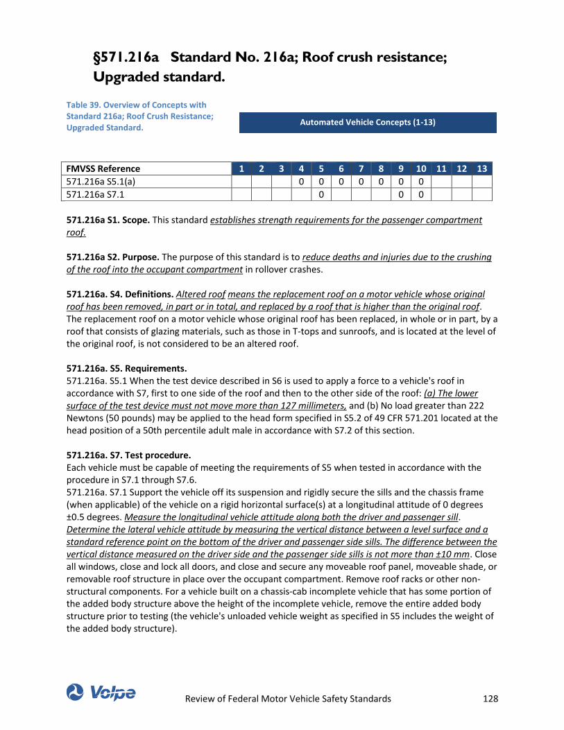
Review of Federal Motor Vehicle Safety Standards 128
§571.216a Standard No. 216a; Roof crush resistance;
Upgraded standard.
Table 39. Overview of Concepts with Standard 216a; Roof Crush Resistance; Upgraded Standard.
FMVSS Reference 1 2 3 4 5 6 7 8 9 10 11 12 13
571.216a S5.1(a) 0 0 0 0 0 0 0
571.216a S7.1 0 0 0
571.216a S1. Scope. This standard establishes strength requirements for the passenger compartment roof. 571.216a S2. Purpose. The purpose of this standard is to reduce deaths and injuries due to the crushing of the roof into the occupant compartment in rollover crashes. 571.216a. S4. Definitions. Altered roof means the replacement roof on a motor vehicle whose original roof has been removed, in part or in total, and replaced by a roof that is higher than the original roof. The replacement roof on a motor vehicle whose original roof has been replaced, in whole or in part, by a roof that consists of glazing materials, such as those in T-tops and sunroofs, and is located at the level of the original roof, is not considered to be an altered roof. 571.216a. S5. Requirements. 571.216a. S5.1 When the test device described in S6 is used to apply a force to a vehicle's roof in accordance with S7, first to one side of the roof and then to the other side of the roof: (a) The lower surface of the test device must not move more than 127 millimeters, and (b) No load greater than 222 Newtons (50 pounds) may be applied to the head form specified in S5.2 of 49 CFR 571.201 located at the head position of a 50th percentile adult male in accordance with S7.2 of this section. 571.216a. S7. Test procedure. Each vehicle must be capable of meeting the requirements of S5 when tested in accordance with the procedure in S7.1 through S7.6. 571.216a. S7.1 Support the vehicle off its suspension and rigidly secure the sills and the chassis frame (when applicable) of the vehicle on a rigid horizontal surface(s) at a longitudinal attitude of 0 degrees ±0.5 degrees. Measure the longitudinal vehicle attitude along both the driver and passenger sill. Determine the lateral vehicle attitude by measuring the vertical distance between a level surface and a standard reference point on the bottom of the driver and passenger side sills. The difference between the vertical distance measured on the driver side and the passenger side sills is not more than ±10 mm. Close all windows, close and lock all doors, and close and secure any moveable roof panel, moveable shade, or removable roof structure in place over the occupant compartment. Remove roof racks or other non-structural components. For a vehicle built on a chassis-cab incomplete vehicle that has some portion of the added body structure above the height of the incomplete vehicle, remove the entire added body structure prior to testing (the vehicle's unloaded vehicle weight as specified in S5 includes the weight of the added body structure).
Automated Vehicle Concepts (1-13)
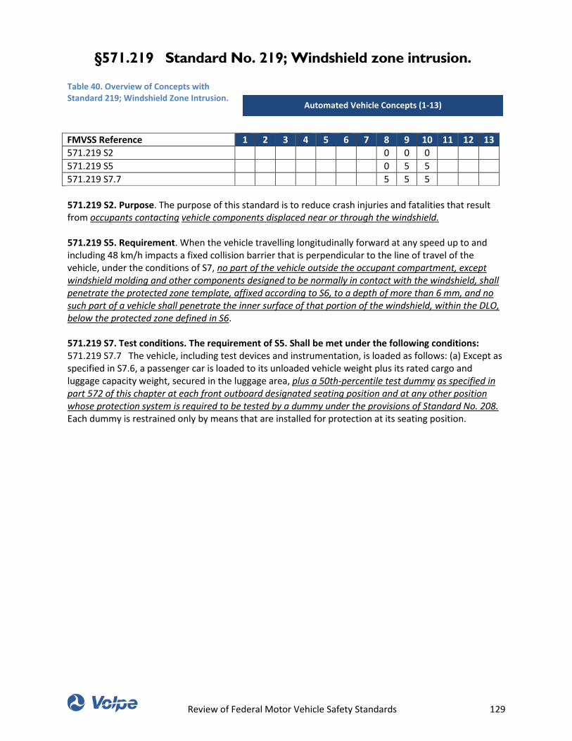
Review of Federal Motor Vehicle Safety Standards 129
§571.219 Standard No. 219; Windshield zone intrusion.
Table 40. Overview of Concepts with Standard 219; Windshield Zone Intrusion.
FMVSS Reference 1 2 3 4 5 6 7 8 9 10 11 12 13
571.219 S2 0 0 0
571.219 S5 0 5 5
571.219 S7.7 5 5 5
571.219 S2. Purpose. The purpose of this standard is to reduce crash injuries and fatalities that result from occupants contacting vehicle components displaced near or through the windshield. 571.219 S5. Requirement. When the vehicle travelling longitudinally forward at any speed up to and including 48 km/h impacts a fixed collision barrier that is perpendicular to the line of travel of the vehicle, under the conditions of S7, no part of the vehicle outside the occupant compartment, except windshield molding and other components designed to be normally in contact with the windshield, shall penetrate the protected zone template, affixed according to S6, to a depth of more than 6 mm, and no such part of a vehicle shall penetrate the inner surface of that portion of the windshield, within the DLO, below the protected zone defined in S6. 571.219 S7. Test conditions. The requirement of S5. Shall be met under the following conditions: 571.219 S7.7 The vehicle, including test devices and instrumentation, is loaded as follows: (a) Except as specified in S7.6, a passenger car is loaded to its unloaded vehicle weight plus its rated cargo and luggage capacity weight, secured in the luggage area, plus a 50th-percentile test dummy as specified in part 572 of this chapter at each front outboard designated seating position and at any other position whose protection system is required to be tested by a dummy under the provisions of Standard No. 208. Each dummy is restrained only by means that are installed for protection at its seating position.
Automated Vehicle Concepts (1-13)
Review of Federal Motor Vehicle Safety Standards 130
§571.222 Standard No. 222; School bus passenger seating
and crash protection.
Table 41. Overview of Concepts with Standard 222; School Bus Passenger Seating and Crash Protection.
FMVSS Reference 1 2 3 4 5 6 7 8 9 10 11 12 13
This table was intentionally left blank. 571.222 S4 Definitions. School bus passenger seat means a seat in a school bus, other than the driver's seat.
Automated Vehicle Concepts (1-13)
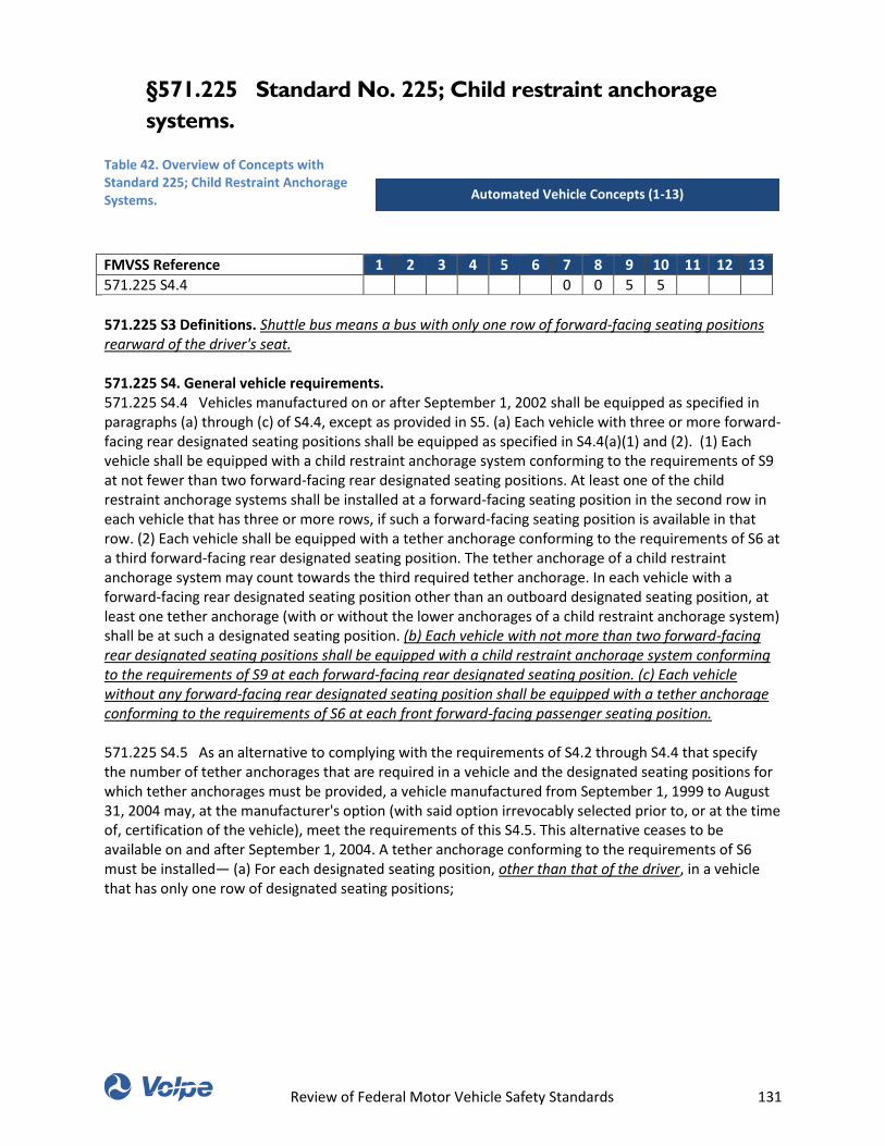
Review of Federal Motor Vehicle Safety Standards 131
§571.225 Standard No. 225; Child restraint anchorage
systems.
Table 42. Overview of Concepts with Standard 225; Child Restraint Anchorage Systems.
FMVSS Reference 1 2 3 4 5 6 7 8 9 10 11 12 13
571.225 S4.4 0 0 5 5
571.225 S3 Definitions. Shuttle bus means a bus with only one row of forward-facing seating positions rearward of the driver's seat. 571.225 S4. General vehicle requirements. 571.225 S4.4 Vehicles manufactured on or after September 1, 2002 shall be equipped as specified in paragraphs (a) through (c) of S4.4, except as provided in S5. (a) Each vehicle with three or more forward-facing rear designated seating positions shall be equipped as specified in S4.4(a)(1) and (2). (1) Each vehicle shall be equipped with a child restraint anchorage system conforming to the requirements of S9 at not fewer than two forward-facing rear designated seating positions. At least one of the child restraint anchorage systems shall be installed at a forward-facing seating position in the second row in each vehicle that has three or more rows, if such a forward-facing seating position is available in that row. (2) Each vehicle shall be equipped with a tether anchorage conforming to the requirements of S6 at a third forward-facing rear designated seating position. The tether anchorage of a child restraint anchorage system may count towards the third required tether anchorage. In each vehicle with a forward-facing rear designated seating position other than an outboard designated seating position, at least one tether anchorage (with or without the lower anchorages of a child restraint anchorage system) shall be at such a designated seating position. (b) Each vehicle with not more than two forward-facing rear designated seating positions shall be equipped with a child restraint anchorage system conforming to the requirements of S9 at each forward-facing rear designated seating position. (c) Each vehicle without any forward-facing rear designated seating position shall be equipped with a tether anchorage conforming to the requirements of S6 at each front forward-facing passenger seating position. 571.225 S4.5 As an alternative to complying with the requirements of S4.2 through S4.4 that specify the number of tether anchorages that are required in a vehicle and the designated seating positions for which tether anchorages must be provided, a vehicle manufactured from September 1, 1999 to August 31, 2004 may, at the manufacturer's option (with said option irrevocably selected prior to, or at the time of, certification of the vehicle), meet the requirements of this S4.5. This alternative ceases to be available on and after September 1, 2004. A tether anchorage conforming to the requirements of S6 must be installed— (a) For each designated seating position, other than that of the driver, in a vehicle that has only one row of designated seating positions;
Automated Vehicle Concepts (1-13)
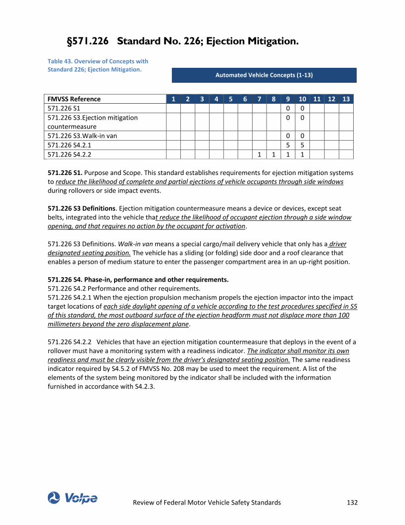
Review of Federal Motor Vehicle Safety Standards 132
§571.226 Standard No. 226; Ejection Mitigation.
Table 43. Overview of Concepts with Standard 226; Ejection Mitigation.
FMVSS Reference 1 2 3 4 5 6 7 8 9 10 11 12 13
571.226 S1 0 0
571.226 S3.Ejection mitigation countermeasure
0 0
571.226 S3.Walk-in van 0 0
571.226 S4.2.1 5 5
571.226 S4.2.2 1 1 1 1
571.226 S1. Purpose and Scope. This standard establishes requirements for ejection mitigation systems to reduce the likelihood of complete and partial ejections of vehicle occupants through side windows during rollovers or side impact events. 571.226 S3 Definitions. Ejection mitigation countermeasure means a device or devices, except seat belts, integrated into the vehicle that reduce the likelihood of occupant ejection through a side window opening, and that requires no action by the occupant for activation. 571.226 S3 Definitions. Walk-in van means a special cargo/mail delivery vehicle that only has a driver designated seating position. The vehicle has a sliding (or folding) side door and a roof clearance that enables a person of medium stature to enter the passenger compartment area in an up-right position. 571.226 S4. Phase-in, performance and other requirements. 571.226 S4.2 Performance and other requirements. 571.226 S4.2.1 When the ejection propulsion mechanism propels the ejection impactor into the impact target locations of each side daylight opening of a vehicle according to the test procedures specified in S5 of this standard, the most outboard surface of the ejection headform must not displace more than 100 millimeters beyond the zero displacement plane. 571.226 S4.2.2 Vehicles that have an ejection mitigation countermeasure that deploys in the event of a rollover must have a monitoring system with a readiness indicator. The indicator shall monitor its own readiness and must be clearly visible from the driver's designated seating position. The same readiness indicator required by S4.5.2 of FMVSS No. 208 may be used to meet the requirement. A list of the elements of the system being monitored by the indicator shall be included with the information furnished in accordance with S4.2.3.
Automated Vehicle Concepts (1-13)
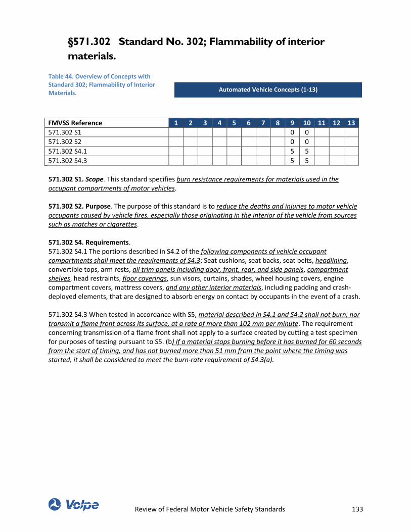
Review of Federal Motor Vehicle Safety Standards 133
§571.302 Standard No. 302; Flammability of interior
materials.
Table 44. Overview of Concepts with Standard 302; Flammability of Interior Materials.
FMVSS Reference 1 2 3 4 5 6 7 8 9 10 11 12 13
571.302 S1 0 0
571.302 S2 0 0
571.302 S4.1 5 5
571.302 S4.3 5 5
571.302 S1. Scope. This standard specifies burn resistance requirements for materials used in the occupant compartments of motor vehicles. 571.302 S2. Purpose. The purpose of this standard is to reduce the deaths and injuries to motor vehicle occupants caused by vehicle fires, especially those originating in the interior of the vehicle from sources such as matches or cigarettes. 571.302 S4. Requirements. 571.302 S4.1 The portions described in S4.2 of the following components of vehicle occupant compartments shall meet the requirements of S4.3: Seat cushions, seat backs, seat belts, headlining, convertible tops, arm rests, all trim panels including door, front, rear, and side panels, compartment shelves, head restraints, floor coverings, sun visors, curtains, shades, wheel housing covers, engine compartment covers, mattress covers, and any other interior materials, including padding and crash-deployed elements, that are designed to absorb energy on contact by occupants in the event of a crash. 571.302 S4.3 When tested in accordance with S5, material described in S4.1 and S4.2 shall not burn, nor transmit a flame front across its surface, at a rate of more than 102 mm per minute. The requirement concerning transmission of a flame front shall not apply to a surface created by cutting a test specimen for purposes of testing pursuant to S5. (b) If a material stops burning before it has burned for 60 seconds from the start of timing, and has not burned more than 51 mm from the point where the timing was started, it shall be considered to meet the burn-rate requirement of S4.3(a).
Automated Vehicle Concepts (1-13)
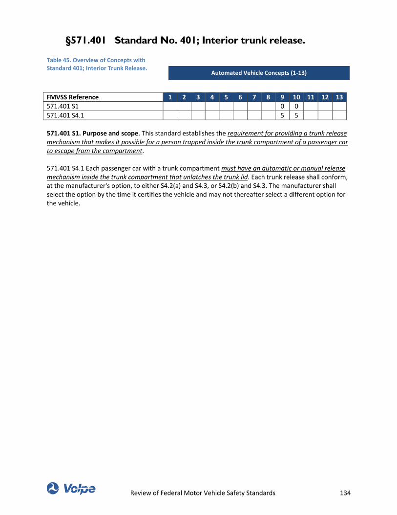
Review of Federal Motor Vehicle Safety Standards 134
§571.401 Standard No. 401; Interior trunk release.
Table 45. Overview of Concepts with Standard 401; Interior Trunk Release.
FMVSS Reference 1 2 3 4 5 6 7 8 9 10 11 12 13
571.401 S1 0 0
571.401 S4.1 5 5
571.401 S1. Purpose and scope. This standard establishes the requirement for providing a trunk release mechanism that makes it possible for a person trapped inside the trunk compartment of a passenger car to escape from the compartment. 571.401 S4.1 Each passenger car with a trunk compartment must have an automatic or manual release mechanism inside the trunk compartment that unlatches the trunk lid. Each trunk release shall conform, at the manufacturer's option, to either S4.2(a) and S4.3, or S4.2(b) and S4.3. The manufacturer shall select the option by the time it certifies the vehicle and may not thereafter select a different option for the vehicle.
Automated Vehicle Concepts (1-13)
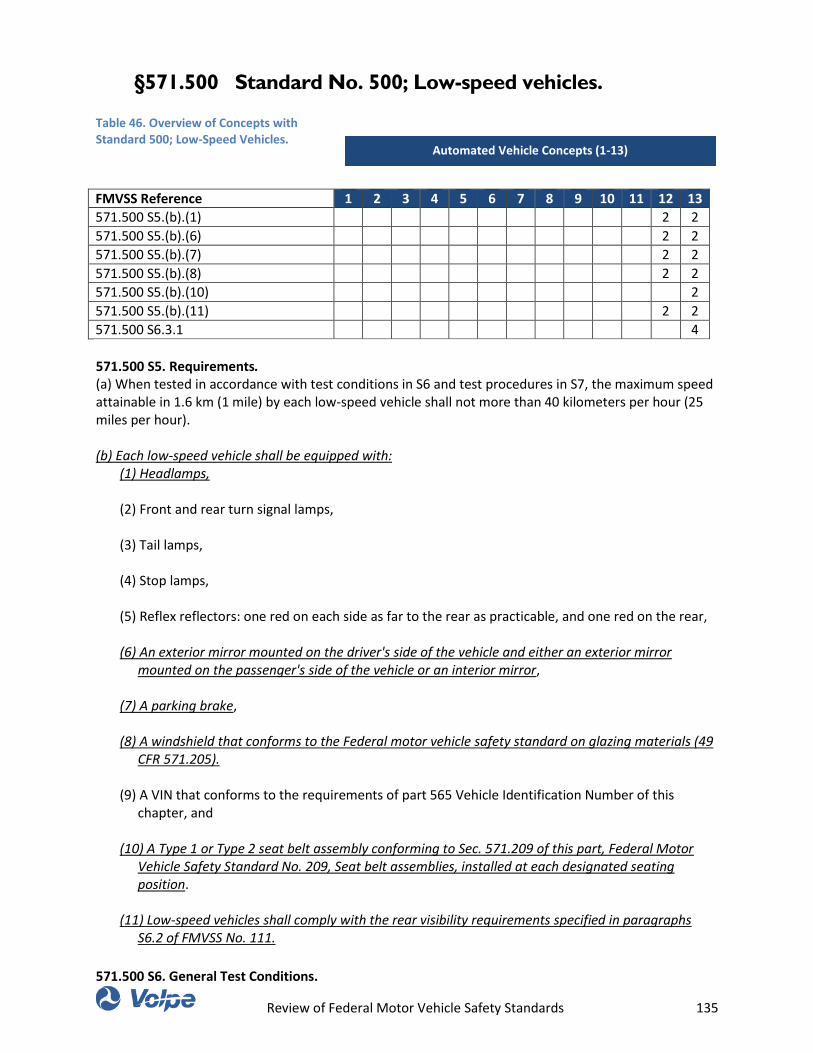
Review of Federal Motor Vehicle Safety Standards 135
§571.500 Standard No. 500; Low-speed vehicles.
Table 46. Overview of Concepts with Standard 500; Low-Speed Vehicles.
FMVSS Reference 1 2 3 4 5 6 7 8 9 10 11 12 13
571.500 S5.(b).(1) 2 2
571.500 S5.(b).(6) 2 2
571.500 S5.(b).(7) 2 2
571.500 S5.(b).(8) 2 2
571.500 S5.(b).(10) 2
571.500 S5.(b).(11) 2 2
571.500 S6.3.1 4
571.500 S5. Requirements. (a) When tested in accordance with test conditions in S6 and test procedures in S7, the maximum speed attainable in 1.6 km (1 mile) by each low-speed vehicle shall not more than 40 kilometers per hour (25 miles per hour). (b) Each low-speed vehicle shall be equipped with:
(1) Headlamps, (2) Front and rear turn signal lamps, (3) Tail lamps, (4) Stop lamps, (5) Reflex reflectors: one red on each side as far to the rear as practicable, and one red on the rear, (6) An exterior mirror mounted on the driver's side of the vehicle and either an exterior mirror
mounted on the passenger's side of the vehicle or an interior mirror, (7) A parking brake, (8) A windshield that conforms to the Federal motor vehicle safety standard on glazing materials (49
CFR 571.205). (9) A VIN that conforms to the requirements of part 565 Vehicle Identification Number of this
chapter, and (10) A Type 1 or Type 2 seat belt assembly conforming to Sec. 571.209 of this part, Federal Motor
Vehicle Safety Standard No. 209, Seat belt assemblies, installed at each designated seating position.
(11) Low-speed vehicles shall comply with the rear visibility requirements specified in paragraphs
S6.2 of FMVSS No. 111.
571.500 S6. General Test Conditions.
Automated Vehicle Concepts (1-13)
Review of Federal Motor Vehicle Safety Standards 136
571.500 S6.3 Vehicle conditions.
571.500 S6.3.1. The test weight for maximum speed is unloaded vehicle weight plus a mass of 78 kg
(170 pounds), including driver and instrumentation.
Review of Federal Motor Vehicle Safety Standards 137
THIS PAGE WAS INTENTIONALLY LEFT BLANK.
Review of Federal Motor Vehicle Safety Standards 138
U.S. Department of Transportation
John A. Volpe National Transportation Systems Center
55 Broadway
Cambridge, MA 02142-1093
617-494-2000 www.volpe.dot.gov