Embed Size (px)
Citation preview

IM3102 04/2019 REV01
POWERTEC i380C ADVANCED
OPERATOR’S MANUAL
ENGLISH
Lincoln Electric Bester Sp. z o.o. ul. Jana III Sobieskiego 19A, 58-263 Bielawa, Poland
www.lincolnelectric.eu

English English I
12/05
THANKS! For having choosen the QUALITY of the Lincoln Electric products. Please Examine Package and Equipment for Damage. Claims for material damaged in shipment must be notified
immediately to the dealer. For future reference record in the table below your equipment identification information. Model Name, Code &
Serial Number can be found on the machine rating plate.
Model Name:
………………...…………………………….………………………………………………………………………………………….. Code & Serial number:
………………….……………………………………………….. …………………………………………………….……………..
Date & Where Purchased:
…………………………………………………………………... ……………………….…………………………………………..
ENGLISH INDEX Technical Specifications .................................................................................................................................................. 1 Electromagnetic Compatibility (EMC) .............................................................................................................................. 2 Safety .............................................................................................................................................................................. 3 Introduction ...................................................................................................................................................................... 4 Installation and Operator Instructions .............................................................................................................................. 4 WEEE ............................................................................................................................................................................ 29 Spare Parts .................................................................................................................................................................... 29 Authorized Service Shops Location ............................................................................................................................... 29 Electrical Schematic ...................................................................................................................................................... 29 Accessories ................................................................................................................................................................... 30
English 1 English
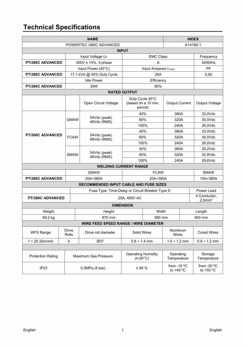
Technical Specifications
NAME INDEX
POWERTEC i380C ADVANCED K14180-1
INPUT
Input Voltage U1 EMC Class Frequency
PTi380C ADVANCED 400V ± 15%, 3-phase A 50/60Hz
Input Power (40°C) Input Amperes I1max PF
PTi380C ADVANCED 17,1 kVA @ 40% Duty Cycle 26A 0,92
Idle Power Efficiency
PTi380C ADVANCED 30W 85%
RATED OUTPUT
Open Circuit Voltage Duty Cycle 40°C
(based on a 10 min. period)
Output Current Output Voltage
PTi380C ADVANCED
54Vdc (peak) 48Vdc (RMS)
40% 380A 33,0Vdc
GMAW 60% 320A 30,0Vdc
100% 240A 26,0Vdc
54Vdc (peak) 48Vdc (RMS)
40% 380A 33.0Vdc
FCAW 60% 320A 30,0Vdc
100% 240A 26,0Vdc
54Vdc (peak) 48Vdc (RMS)
40% 380A 35,2Vdc
SMAW 60% 320A 32,8Vdc
100% 240A 29,6Vdc
WELDING CURRENT RANGE
GMAW FCAW SMAW
PTi380C ADVANCED 20A÷380A 20A÷380A 10A÷380A
RECOMMENDED INPUT CABLE AND FUSE SIZES
Fuse Type: Time-Delay or Circuit Breaker Type D Power Lead
PTi380C ADVANCED 25A, 400V AC 4 Conductor,
2,5mm2
DIMENSION
Weight Height Width Length
69,2 kg 870 mm 560 mm 900 mm
WIRE FEED SPEED RANGE / WIRE DIAMETER
WFS Range Drive Rolls
Drive roll diameter Solid Wires Aluminum
Wires Cored Wires
1 ÷ 20,32m/min 4 Ø37 0.8 ÷ 1.4 mm 1.0 ÷ 1.2 mm 0.9 ÷ 1.2 mm
Protection Rating Maximum Gas Pressure Operating Humidity
(t=20°C) Operating
Temperature Storage
Temperature
IP23 0,5MPa (5 bar) ≤ 90 % from -10 ºC to +40 ºC
from -20 ºC to +55 ºC
English 2 English
Electromagnetic Compatibility (EMC) 11/04
This machine has been designed in accordance with all relevant directives and standards. However, it may still generate electromagnetic disturbances that can affect other systems like telecommunications (telephone, radio, and television) or other safety systems. These disturbances can cause safety problems in the affected systems. Read and understand this section to eliminate or reduce the amount of electromagnetic disturbance generated by this machine.
WARNING Provided that the public low voltage system impedance at the point of common coupling is lower than: 56,4 mΩ for the Powertec i380. This equipment is compliant with IEC 61000-3-11 and IEC-3-12 and can be connected to public lowvoltage systems. It is the responsibility of the installer or user of the equipment to ensure, by consultation with the distribution network operator if necessary, that the system impedance complies with the impedance restrictions. Consider the following guidelines to reduce electromagnetic emissions from the machine. Connect the machine to the input supply according to this manual. If disturbances occur if may be necessary to take
additional precautions such as filtering the input supply. The output cables should be kept as short as possible and should be positioned together. If possible connect the
work piece to ground in order to reduce the electromagnetic emissions. The operator must check that connecting the work piece to ground does not cause problems or unsafe operating conditions for personnel and equipment.
Shielding of cables in the work area can reduce electromagnetic emissions. This may be necessary for special applications.
WARNING The Class A equipment is not intended for use in residential locations where the electrical power is provided by the public low-voltage supply system. There may be potential difficulties in ensuring electromagnetic compatibility in those locations, due to conducted as well as radiated disturbances.
WARNING While a high electromagnetic field occurs, a welding current can fluctuate.
English 3 English
Safety 01/11
WARNING This equipment must be used by qualified personnel. Be sure that all installation, operation, maintenance and repair procedures are performed only by qualified person. Read and understand this manual before operating this equipment. Failure to follow the instructions in this manual could cause serious personal injury, loss of life, or damage to this equipment. Read and understand the following explanations of the warning symbols. Lincoln Electric is not responsible for damages caused by improper installation, improper care or abnormal operation.
WARNING: This symbol indicates that instructions must be followed to avoid serious personal injury, loss of life, or damage to this equipment. Protect yourself and others from possible serious injury or death.
READ AND UNDERSTAND INSTRUCTIONS: Read and understand this manual before operating this equipment. Arc welding can be hazardous. Failure to follow the instructions in this manual could cause serious personal injury, loss of life, or damage to this equipment.
ELECTRIC SHOCK CAN KILL: Welding equipment generates high voltages. Do not touch the electrode, work clamp, or connected work pieces when this equipment is on. Insulate yourself from the electrode, work clamp, and connected work pieces.
ELECTRICALLY POWERED EQUIPMENT: Turn off input power using the disconnect switch at the fuse box before working on this equipment. Ground this equipment in accordance with local electrical regulations.
ELECTRICALLY POWERED EQUIPMENT: Regularly inspect the input, electrode, and work clamp cables. If any insulation damage exists replace the cable immediately. Do not place the electrode holder directly on the welding table or any other surface in contact with the work clamp to avoid the risk of accidental arc ignition.
ELECTRIC AND MAGNETIC FIELDS MAY BE DANGEROUS: Electric current flowing through any conductor creates electric and magnetic fields (EMF). EMF fields may interfere with some pacemakers, and welders having a pacemaker shall consult their physician before operating this equipment.
CE COMPLIANCE: This equipment complies with the European Community Directives.
ARTIFICIAL OPTICAL RADIATION: According with the requirements in 2006/25/EC Directive and EN 12198 Standard, the equipment is a category 2. It makes mandatory the adoption of Personal Protective Equipments (PPE) having filter with a protection degree up to a maximum of 15, as required by EN169 Standard.
FUMES AND GASES CAN BE DANGEROUS: Welding may produce fumes and gases hazardous to health. Avoid breathing these fumes and gases. To avoid these dangers the operator must use enough ventilation or exhaust to keep fumes and gases away from the breathing zone.
ARC RAYS CAN BURN: Use a shield with the proper filter and cover plates to protect your eyes from sparks and the rays of the arc when welding or observing. Use suitable clothing made from durable flame-resistant material to protect you skin and that of your helpers. Protect other nearby personnel with suitable, non-flammable screening and warn them not to watch the arc nor expose themselves to the arc.
WELDING SPARKS CAN CAUSE FIRE OR EXPLOSION: Remove fire hazards from the welding area and have a fire extinguisher readily available. Welding sparks and hot materials from the welding process can easily go through small cracks and openings to adjacent areas. Do not weld on any tanks, drums, containers, or material until the proper steps have been taken to insure that no flammable or toxic vapors will be present. Never operate this equipment when flammable gases, vapors or liquid combustibles are present.
WELDED MATERIALS CAN BURN: Welding generates a large amount of heat. Hot surfaces and materials in work area can cause serious burns. Use gloves and pliers when touching or moving materials in the work area.
SAFETY MARK: This equipment is suitable for supplying power for welding operations carried out in an environment with increased hazard of electric shock.
English 4 English
CYLINDER MAY EXPLODE IF DAMAGED: Use only compressed gas cylinders containing the correct shielding gas for the process used and properly operating regulators designed for the gas and pressure used. Always keep cylinders in an upright position securely chained to a fixed support. Do not move or transport gas cylinders with the protection cap removed. Do not allow the electrode, electrode holder, work clamp or any other electrically live part to touch a gas cylinder. Gas cylinders must be located away from areas where they may be subjected to physical damage or the welding process including sparks and heat sources.
MOVING PARTS ARE DANGEROUS: There are moving mechanical parts in this machine, which can cause serious injury. Keep your hands, body and clothing away from those parts during machine starting, operating and servicing.
The manufacturer reserves the Right to make changes and/or improvements in design without upgrade at the same time the operator’s manual.
Introduction
General Description The welding machines POWERTEC i380C ADVANCED enables welding: GMAW (MIG/MAG), FCAW (Flux-Cored), SMAW (MMA),
The following equipment has been added to POWERTEC i380C ADVANCED Work lead – 3m, Gas hose – 2m, Driving roll V1.0/V1.2 for solid wire (mounted in the
wire feeder). Recommended equipment, which can be bought by user, was mentioned in the chapter "Accessories".
Installation and Operator Instructions Read this entire section before installation or operation of the machine.
Location and Environment This machine will operate in harsh environments. However, it is important that simple preventative measures are followed to assure long life and reliable operation. Do not place or operate this machine on a surface
with an incline greater than 15° from horizontal. Do not use this machine for pipe thawing. This machine must be located where there is free
circulation of clean air without restrictions for air movement to and from the air vents. Do not cover the machine with paper, cloth or rags when switched on.
Dirt and dust that can be drawn into the machine should be kept to a minimum.
This machine has a protection rating of IP23. Keep it dry when possible and do not place it on wet ground or in puddles.
Locate the machine away from radio controlled machinery. Normal operation may adversely affect the operation of nearby radio controlled machinery, which may result in injury or equipment damage. Read the section on electromagnetic compatibility in this manual.
Do not operate in areas with an ambient temperature greater than 40°C.
Duty cycle and Overheating The duty cycle of a welding machine is the percentage of time in a 10 minute cycle at which the welder can operate the machine at rated welding current. Example: 60% duty cycle
Welding for 6 minutes. Break for 4 minutes.
Excessive extension of the duty cycle will cause the thermal protection circuit to activate.
Minutes or decrease
Duty Cycle
English 5 English
Input Supply Connection
WARNING Only a qualified electrician can connect the welding machine to the supply network. Installation had to be made in accordance with the appropriate National Electrical Code and local regulations. Check the input voltage, phase and frequency supplied to this machine before turning it on. Verify the connection of ground wires from the machine to the input source. The welding machine POWERTEC i380C ADVANCED must be connected to a correctly installed plug-in socket with an earth pin. Input voltage is 400 Vac 50/60Hz. For more information about input supply refer to the technical specification section of this manual and to the rating plate of the machine. Make sure that the amount of mains power available from the input supply is adequate for normal operation of the machine. The necessary delayed fuse or circuit breaker and cable sizes are indicated in the technical specification section of this manual.
WARNING The welding machine can be supplied from a power generator of output power at least 30% larger than input power of the welding machine.
WARNING When powering the machine from a generator be sure to turn off welder first, before generator is shut down, in order to prevent damage to welder!
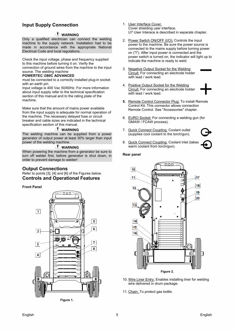
Output Connections Refer to points [3], [4] and [6] of the Figures below.
Controls and Operational Features Front Panel
Figure 1.
1. User Interface Cover. Cover shielding user interface. U7 User Interace is described in separate chapter.
2. Power Switch ON/OFF (I/O): Controls the input power to the machine. Be sure the power source is connected to the mains supply before turning power on ("I"). After input power is connected and the power switch is turned on, the indicator will light up to indicate the machine is ready to weld.
3. Negative Output Socket for the Welding Circuit: For connecting an electrode holder with lead / work lead.
4. Positive Output Socket for the Welding Circuit: For connecting an electrode holder with lead / work lead.
5. Remote Control Connector Plug: To install Remote
Control Kit. This connector allows connection Remote Control. See "Accessories" chapter.
6. EURO Socket: For connecting a welding gun (for
GMAW / FCAW process).
7. Quick Connect Coupling: Coolant outlet (supplies cool coolant to the torch/gun).
8. Quick Connect Coupling: Coolant inlet (takes warm coolant from torch/gun).
Rear panel
Figure 2.
10. Wire Liner Entry: Enables installing liner for welding
wire delivered in drum package. 11. Chain: To protect gas bottle.
English 6 English
12. Gas hose. 13. Work Lead. 14. Cover bracket: To intall cooler cable holder bracket. 15. Quick Connect Coupling: Coolant inlet
(supplies cool coolant to the torch/gun). 16. Quick Connect Coupling: Coolant outlet
(takes warm coolant from torch/gun). 17. Supply Plug: For CO2 gas heater kit (see
“Accessories” chapter). 18. Power Lead (5m): Connect the supply plug to the
existing input cable that is rated for the machine as indicated in this manual, and conforms to all applicable standards. This connection shall be performed by a qualified person only.
19. Gas Connector: Connection for gas line. 20. Gas Flow Regulator Plug: Gas flow regulator can be
purchased separately (see “Accessories” chapter).
Internal Controls
Figure 3.
21. Cold Inch/ Gas Purge Switch: This switch enables
wire feeding or gas flow without turning on output voltage.
22. USB Receptacle Type A:
For USB memory stick connection. For machine software update and service purpose.
23. Spooled Wire (for GMAW / FCAW): The machine
does not include a spooled wire. 24. Fuse F1: Use the 2A/400V (6,3x32mm) low blow
fuse 25. Wire drive feeding system: 4-Roll wire drive
mechanisms with quick-change feed rolls. 26. Terminal Block of Changing Polarity Plug (for GMAW
/ FCAW-SS process): This terminal block enables to set the welding polarity (+ ; -), which will be given at the welding gun
27. Wire Spool Support: Maximum 16kg spools. Accepts
plastic, steel and fiber spools onto 51 mm spindle. Note: Plastic Brake Nut has a Left-hand thread.
English 7 English
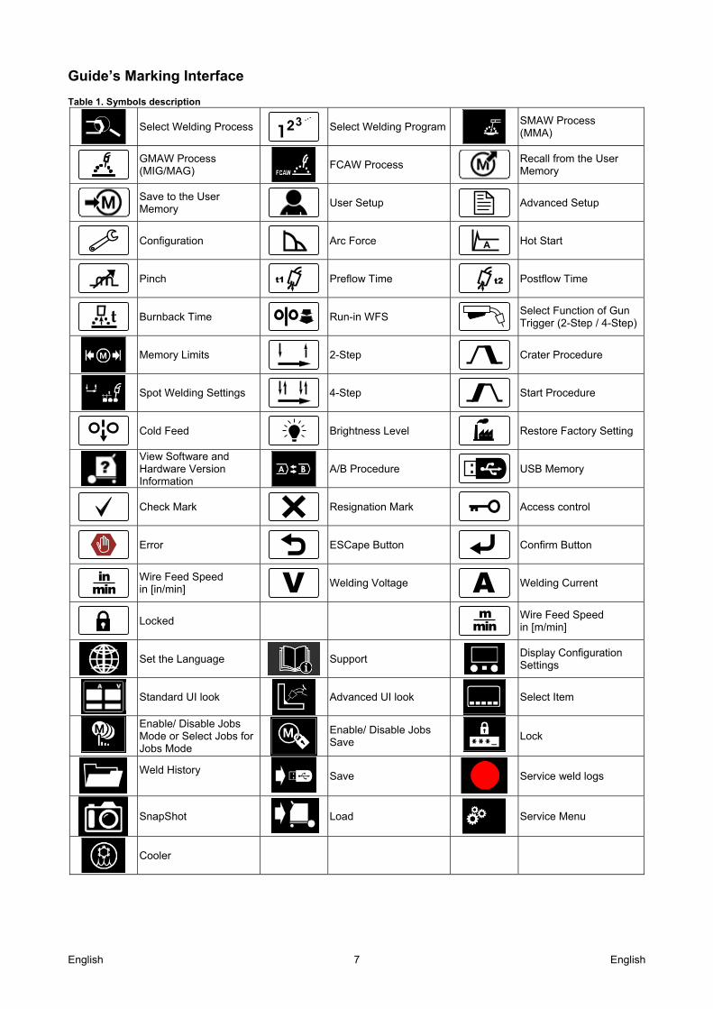
Guide’s Marking Interface Table 1. Symbols description
Select Welding Process 3 ...
Select Welding Program
SMAW Process (MMA)
GMAW Process (MIG/MAG)
FCAW Process
Recall from the User Memory
Save to the User Memory
User Setup
Advanced Setup
Configuration
Arc Force A
Hot Start
Pinch t1
Preflow Time t2
Postflow Time
Burnback Time
Run-in WFS
Select Function of Gun Trigger (2-Step / 4-Step)
Memory Limits
2-Step
Crater Procedure
Spot Welding Settings
4-Step
Start Procedure
Cold Feed
Brightness Level
Restore Factory Setting
View Software and Hardware Version Information
A/B Procedure
USB Memory
Check Mark
Resignation Mark
Access control
Error
ESCape Button
Confirm Button
minin
Wire Feed Speed in [in/min] V
Welding Voltage A Welding Current
Locked min
m
Wire Feed Speed in [m/min]
Set the Language
Support
Display Configuration Settings
Standard UI look
Advanced UI look
Select Item
Enable/ Disable Jobs Mode or Select Jobs for Jobs Mode
Enable/ Disable Jobs Save
Lock
Weld History
Save
Service weld logs
SnapShot
Load
Service Menu
Cooler
English 8 English
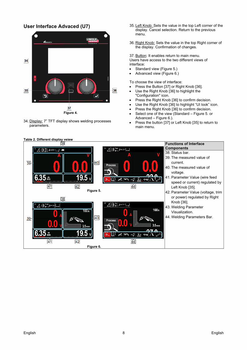
User Interface Advaced (U7)
Figure 4.
34. Display: 7” TFT display shows welding processes
parameters.
35. Left Knob: Sets the value in the top Left corner of the display. Cancel selection. Return to the previous menu.
36. Right Knob: Sets the value in the top Right corner of
the display. Confirmation of changes. 37. Button: It enables return to main menu. Users have access to the two different views of interface: Standard view (Figure 5.) Advanced view (Figure 6.) To choose the view of interface: Press the Button [37] or Right Knob [36]. Use the Right Knob [36] to highlight the
"Configuration" icon. Press the Right Knob [36] to confirm decision. Use the Right Knob [36] to highlight “UI look” icon. Press the Right Knob [36] to confirm decision. Select one of the view (Standard – Figure 5. or
Advanced – Figure 6.). Press the button [37] or Left Knob [35] to return to
main menu.
Table 2. Different display veiew
Figure 5.
Figure 6.
Functions of Interface Components 38. Status bar. 39. The measured value of
current. 40. The measured value of
voltage. 41. Parameter Value (wire feed
speed or current) regulated by Left Knob [35].
42. Parameter Value (voltage, trim or power) regulated by Right Knob [36].
43. Welding Parameter Visualization.
44. Welding Parameters Bar.
English 9 English
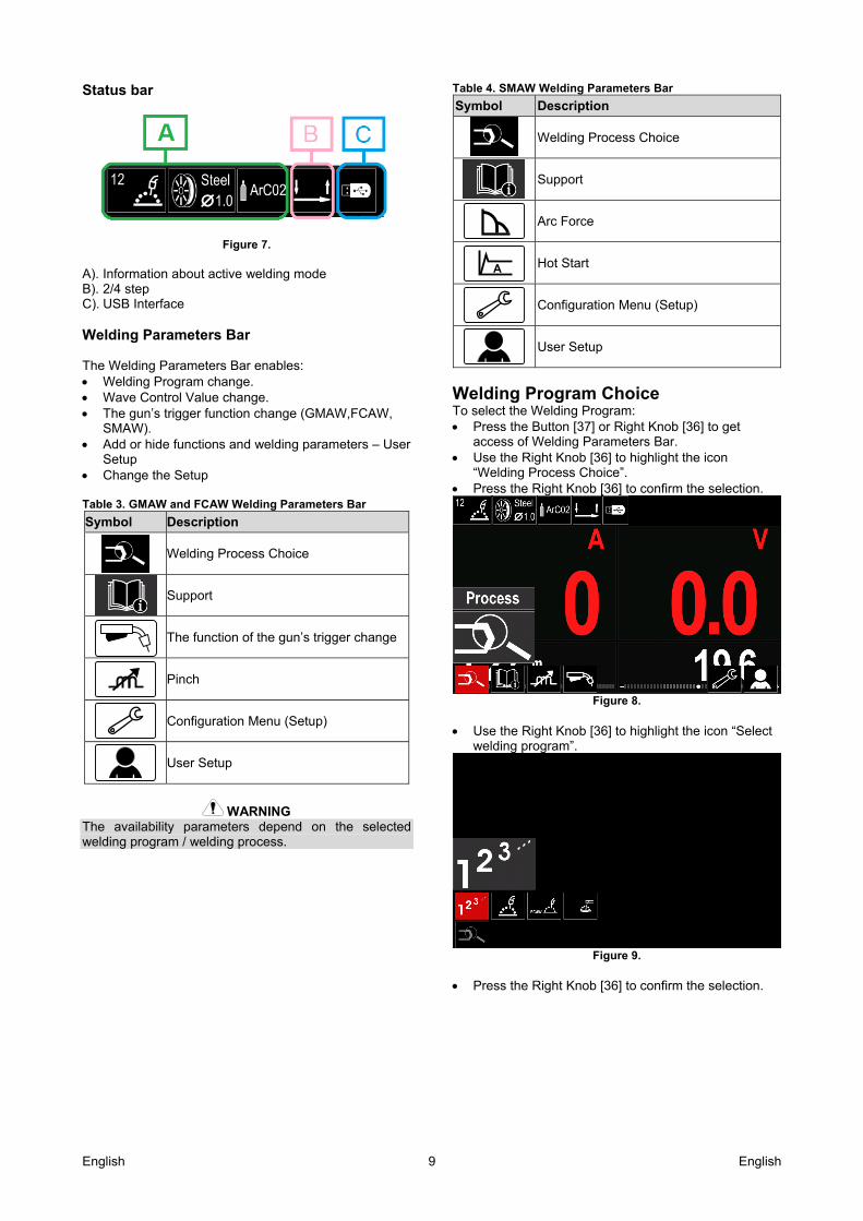
Status bar
Figure 7.
A). Information about active welding mode B). 2/4 step C). USB Interface Welding Parameters Bar The Welding Parameters Bar enables: Welding Program change. Wave Control Value change. The gun’s trigger function change (GMAW,FCAW,
SMAW). Add or hide functions and welding parameters – User
Setup Change the Setup Table 3. GMAW and FCAW Welding Parameters Bar
Symbol Description
Welding Process Choice
Support
The function of the gun’s trigger change
Pinch
Configuration Menu (Setup)
User Setup
WARNING The availability parameters depend on the selected welding program / welding process.
Table 4. SMAW Welding Parameters Bar
Symbol Description
Welding Process Choice
Support
Arc Force
A
Hot Start
Configuration Menu (Setup)
User Setup
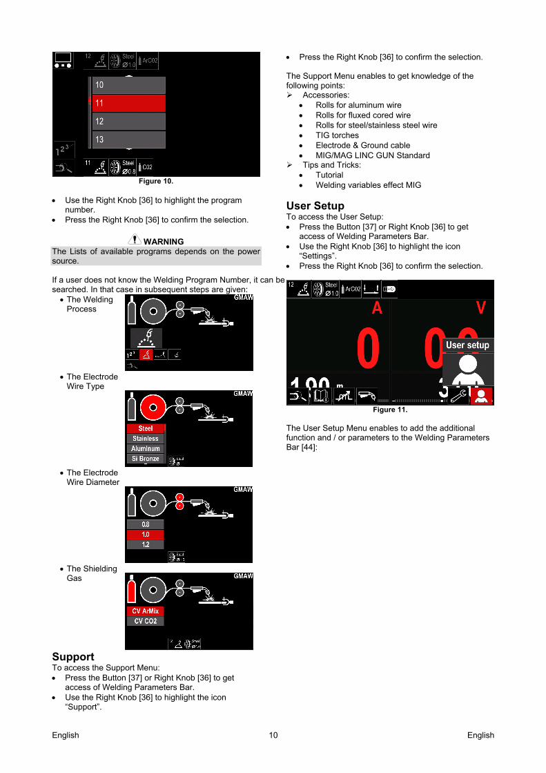
Welding Program Choice To select the Welding Program: Press the Button [37] or Right Knob [36] to get
access of Welding Parameters Bar. Use the Right Knob [36] to highlight the icon
“Welding Process Choice”. Press the Right Knob [36] to confirm the selection.
Figure 8.
Use the Right Knob [36] to highlight the icon “Select
welding program”.
Figure 9.
Press the Right Knob [36] to confirm the selection.
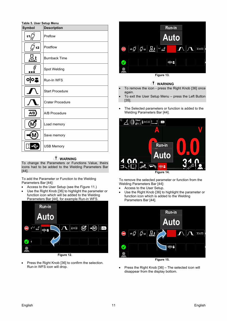
English 10 English
Figure 10.
Use the Right Knob [36] to highlight the program
number. Press the Right Knob [36] to confirm the selection.
WARNING The Lists of available programs depends on the power source. If a user does not know the Welding Program Number, it can be searched. In that case in subsequent steps are given: The Welding
Process
The Electrode
Wire Type
The Electrode
Wire Diameter
The Shielding
Gas
Support To access the Support Menu: Press the Button [37] or Right Knob [36] to get
access of Welding Parameters Bar. Use the Right Knob [36] to highlight the icon
“Support”.
Press the Right Knob [36] to confirm the selection. The Support Menu enables to get knowledge of the following points: Accessories:
Rolls for aluminum wire Rolls for fluxed cored wire Rolls for steel/stainless steel wire TIG torches Electrode & Ground cable MIG/MAG LINC GUN Standard
Tips and Tricks: Tutorial Welding variables effect MIG
User Setup To access the User Setup: Press the Button [37] or Right Knob [36] to get
access of Welding Parameters Bar. Use the Right Knob [36] to highlight the icon
“Settings”. Press the Right Knob [36] to confirm the selection.
Figure 11.
The User Setup Menu enables to add the additional function and / or parameters to the Welding Parameters Bar [44]:
English 11 English
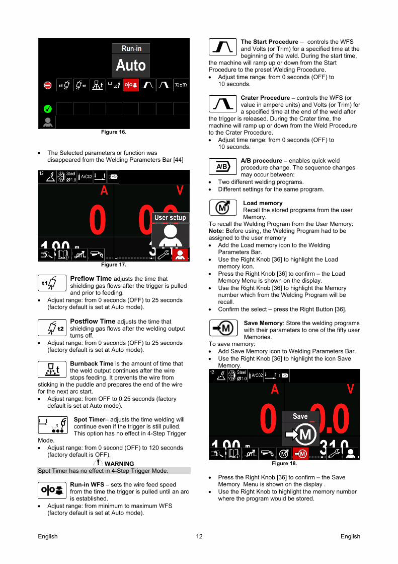
Table 5. User Setup Menu
Symbol Description
t1
Preflow
t2
Postflow
Burnback Time
Spot Welding
Run-In WFS
Start Procedure
Crater Procedure
A/B
A/B Procedure
Load memory
Save memory
USB Memory
WARNING To change the Parameters or Functions Value, theirs icons had to be added to the Welding Parameters Bar [44]. To add the Parameter or Function to the Welding Parameters Bar [44]: Access to the User Setup (see the Figure 11.) Use the Right Knob [36] to highlight the parameter or
function icon which will be added to the Welding Parameters Bar [44], for example Run-in WFS.
Figure 12.
Press the Right Knob [36] to confirm the selection.
Run-in WFS icon will drop.
Figure 13.
WARNING To remove the icon - press the Right Knob [36] once
again. To exit the User Setup Menu – press the Left Button
[35]. The Selected parameters or function is added to the
Welding Parameters Bar [44].
Figure 14.
To remove the selected parameter or function from the Welding Parameters Bar [44]: Access to the User Setup. Use the Right Knob [36] to highlight the parameter or
function icon which is added to the Welding Parameters Bar [44].
Figure 15.
Press the Right Knob [36] – The selected icon will
disappear from the display bottom.
English 12 English
Figure 16.
The Selected parameters or function was
disappeared from the Welding Parameters Bar [44]
Figure 17.
Preflow Time adjusts the time that shielding gas flows after the trigger is pulled and prior to feeding.
Adjust range: from 0 seconds (OFF) to 25 seconds (factory default is set at Auto mode).
Postflow Time adjusts the time that shielding gas flows after the welding output turns off.
Adjust range: from 0 seconds (OFF) to 25 seconds (factory default is set at Auto mode).
Burnback Time is the amount of time that the weld output continues after the wire stops feeding. It prevents the wire from
sticking in the puddle and prepares the end of the wire for the next arc start. Adjust range: from OFF to 0.25 seconds (factory
default is set at Auto mode).
Spot Timer– adjusts the time welding will continue even if the trigger is still pulled. This option has no effect in 4-Step Trigger
Mode. Adjust range: from 0 second (OFF) to 120 seconds
(factory default is OFF).
WARNING Spot Timer has no effect in 4-Step Trigger Mode.
Run-in WFS – sets the wire feed speed from the time the trigger is pulled until an arc is established.
Adjust range: from minimum to maximum WFS (factory default is set at Auto mode).
The Start Procedure – controls the WFS and Volts (or Trim) for a specified time at the beginning of the weld. During the start time,
the machine will ramp up or down from the Start Procedure to the preset Welding Procedure. Adjust time range: from 0 seconds (OFF) to
10 seconds.
Crater Procedure – controls the WFS (or value in ampere units) and Volts (or Trim) for a specified time at the end of the weld after
the trigger is released. During the Crater time, the machine will ramp up or down from the Weld Procedure to the Crater Procedure. Adjust time range: from 0 seconds (OFF) to
10 seconds.
A/B procedure – enables quick weld procedure change. The sequence changes may occur between:
Two different welding programs. Different settings for the same program.
Load memory Recall the stored programs from the user Memory.
To recall the Welding Program from the User Memory: Note: Before using, the Welding Program had to be assigned to the user memory Add the Load memory icon to the Welding
Parameters Bar. Use the Right Knob [36] to highlight the Load
memory icon. Press the Right Knob [36] to confirm – the Load
Memory Menu is shown on the display. Use the Right Knob [36] to highlight the Memory
number which from the Welding Program will be recall.
Confirm the select – press the Right Button [36]. Save Memory: Store the welding programs with their parameters to one of the fifty user Memories.
To save memory: Add Save Memory icon to Welding Parameters Bar. Use the Right Knob [36] to highlight the icon Save
Memory.
Figure 18.
Press the Right Knob [36] to confirm – the Save
Memory Menu is shown on the display . Use the Right Knob to highlight the memory number
where the program would be stored.
A/B
t2
t1
English 13 English
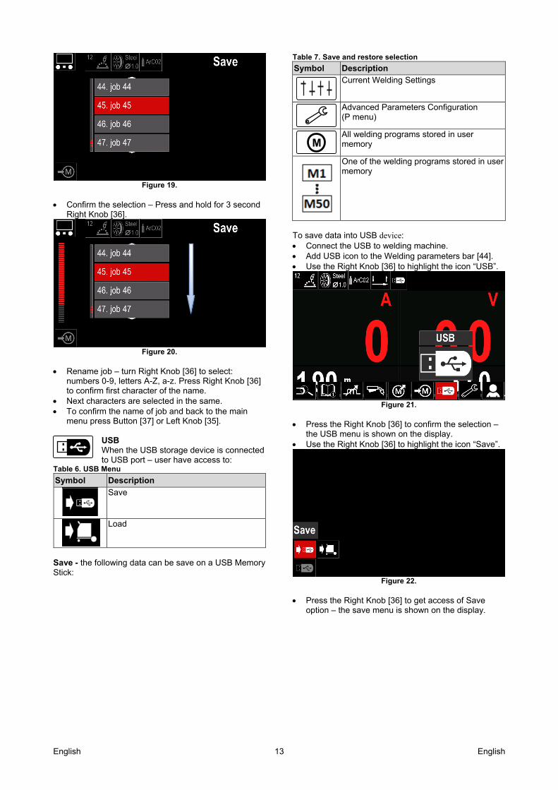
Figure 19.
Confirm the selection – Press and hold for 3 second
Right Knob [36].
Figure 20.
Rename job – turn Right Knob [36] to select:
numbers 0-9, letters A-Z, a-z. Press Right Knob [36] to confirm first character of the name.
Next characters are selected in the same. To confirm the name of job and back to the main
menu press Button [37] or Left Knob [35].
USB When the USB storage device is connected to USB port – user have access to:
Table 6. USB Menu
Symbol Description
Save
Load
Save - the following data can be save on a USB Memory Stick:
Table 7. Save and restore selection
Symbol Description
Current Welding Settings
Advanced Parameters Configuration (P menu)
M
All welding programs stored in user memory
One of the welding programs stored in user memory
To save data into USB device: Connect the USB to welding machine. Add USB icon to the Welding parameters bar [44]. Use the Right Knob [36] to highlight the icon “USB”.
Figure 21.
Press the Right Knob [36] to confirm the selection –
the USB menu is shown on the display. Use the Right Knob [36] to highlight the icon “Save”.
Figure 22.
Press the Right Knob [36] to get access of Save
option – the save menu is shown on the display.
English 14 English
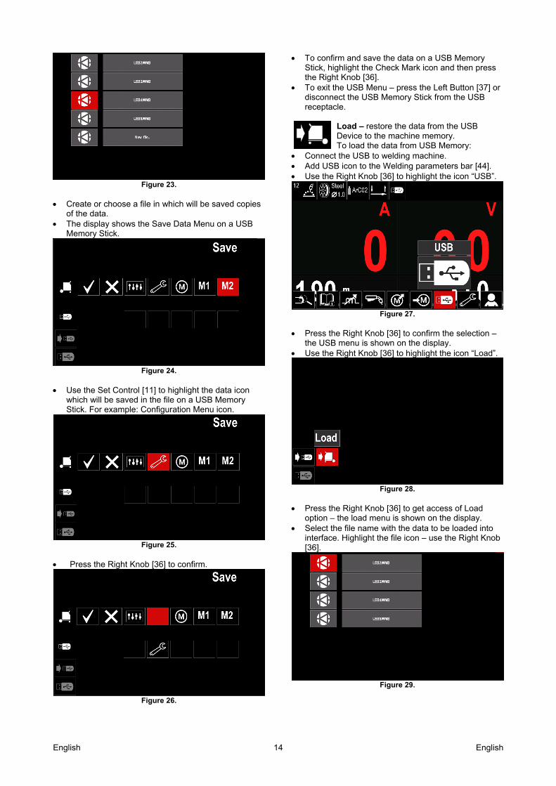
Figure 23.
Create or choose a file in which will be saved copies
of the data. The display shows the Save Data Menu on a USB
Memory Stick.
Figure 24.
Use the Set Control [11] to highlight the data icon
which will be saved in the file on a USB Memory Stick. For example: Configuration Menu icon.
Figure 25.
Press the Right Knob [36] to confirm.
Figure 26.
To confirm and save the data on a USB Memory Stick, highlight the Check Mark icon and then press the Right Knob [36].
To exit the USB Menu – press the Left Button [37] or disconnect the USB Memory Stick from the USB receptacle.
Load – restore the data from the USB Device to the machine memory. To load the data from USB Memory:
Connect the USB to welding machine. Add USB icon to the Welding parameters bar [44]. Use the Right Knob [36] to highlight the icon “USB”.
Figure 27.
Press the Right Knob [36] to confirm the selection –
the USB menu is shown on the display. Use the Right Knob [36] to highlight the icon “Load”.
Figure 28.
Press the Right Knob [36] to get access of Load
option – the load menu is shown on the display. Select the file name with the data to be loaded into
interface. Highlight the file icon – use the Right Knob [36].
Figure 29.
English 15 English
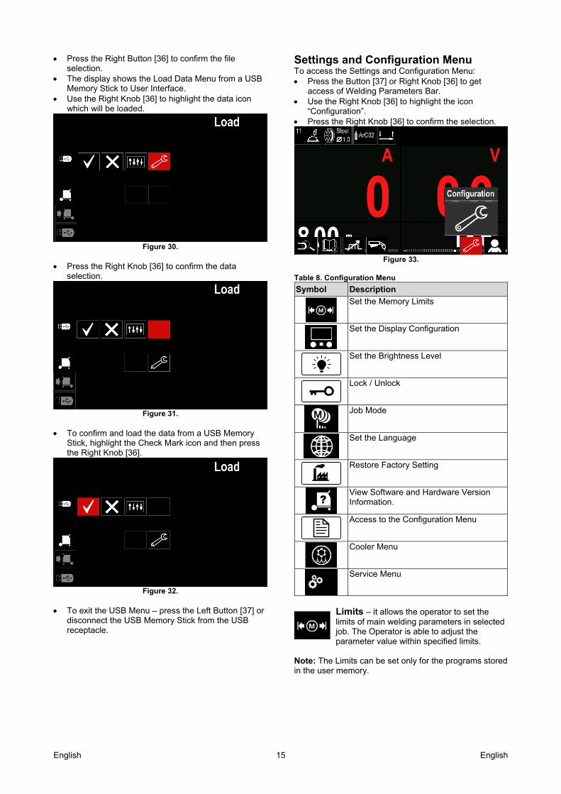
Press the Right Button [36] to confirm the file selection.
The display shows the Load Data Menu from a USB Memory Stick to User Interface.
Use the Right Knob [36] to highlight the data icon which will be loaded.
Figure 30.
Press the Right Knob [36] to confirm the data
selection.
Figure 31.
To confirm and load the data from a USB Memory
Stick, highlight the Check Mark icon and then press the Right Knob [36].
Figure 32.
To exit the USB Menu – press the Left Button [37] or
disconnect the USB Memory Stick from the USB receptacle.
Settings and Configuration Menu To access the Settings and Configuration Menu: Press the Button [37] or Right Knob [36] to get
access of Welding Parameters Bar. Use the Right Knob [36] to highlight the icon
“Configuration”. Press the Right Knob [36] to confirm the selection.
Figure 33.
Table 8. Configuration Menu
Symbol Description
Set the Memory Limits
Set the Display Configuration
Set the Brightness Level
Lock / Unlock
Job Mode
Set the Language
Restore Factory Setting
View Software and Hardware Version Information.
Access to the Configuration Menu
Cooler Menu
Service Menu
Limits – it allows the operator to set the limits of main welding parameters in selected job. The Operator is able to adjust the parameter value within specified limits.
Note: The Limits can be set only for the programs stored in the user memory.
English 16 English
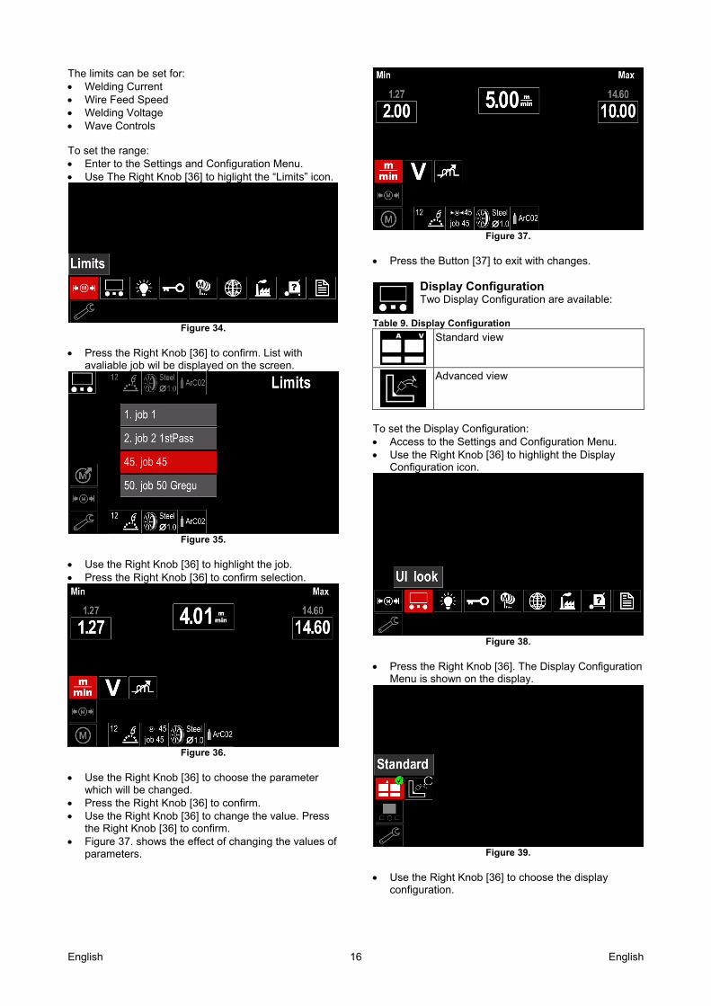
The limits can be set for: Welding Current Wire Feed Speed Welding Voltage Wave Controls To set the range: Enter to the Settings and Configuration Menu. Use The Right Knob [36] to higlight the “Limits” icon.
Figure 34.
Press the Right Knob [36] to confirm. List with
avaliable job wil be displayed on the screen.
Figure 35.
Use the Right Knob [36] to highlight the job. Press the Right Knob [36] to confirm selection.
Figure 36.
Use the Right Knob [36] to choose the parameter
which will be changed. Press the Right Knob [36] to confirm. Use the Right Knob [36] to change the value. Press
the Right Knob [36] to confirm. Figure 37. shows the effect of changing the values of
parameters.
Figure 37.
Press the Button [37] to exit with changes.
Display Configuration Two Display Configuration are available:
Table 9. Display Configuration
Standard view
Advanced view
To set the Display Configuration: Access to the Settings and Configuration Menu. Use the Right Knob [36] to highlight the Display
Configuration icon.
Figure 38.
Press the Right Knob [36]. The Display Configuration
Menu is shown on the display.
Figure 39.
Use the Right Knob [36] to choose the display
configuration.
English 17 English
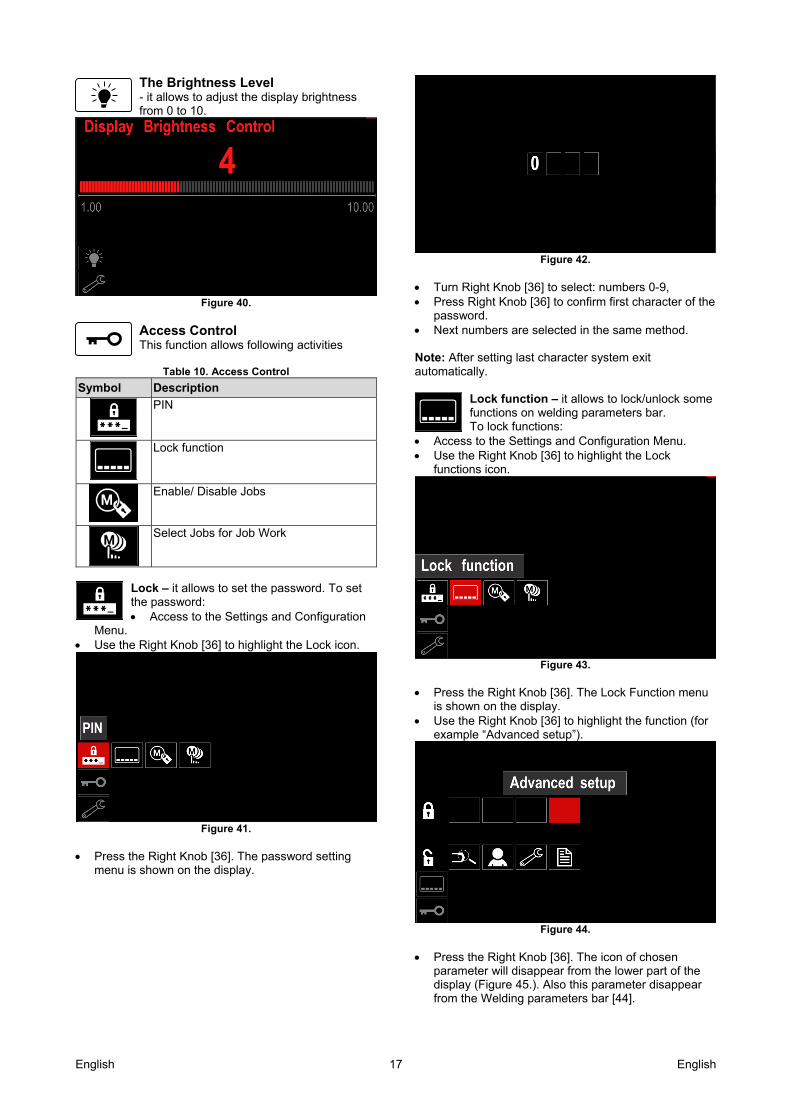
The Brightness Level - it allows to adjust the display brightness from 0 to 10.
Figure 40.
Access Control This function allows following activities
Table 10. Access Control
Symbol Description
PIN
Lock function
Enable/ Disable Jobs
Select Jobs for Job Work
Lock – it allows to set the password. To set the password: Access to the Settings and Configuration
Menu. Use the Right Knob [36] to highlight the Lock icon.
Figure 41.
Press the Right Knob [36]. The password setting
menu is shown on the display.
Figure 42.
Turn Right Knob [36] to select: numbers 0-9, Press Right Knob [36] to confirm first character of the
password. Next numbers are selected in the same method. Note: After setting last character system exit automatically.
Lock function – it allows to lock/unlock some functions on welding parameters bar. To lock functions:
Access to the Settings and Configuration Menu. Use the Right Knob [36] to highlight the Lock
functions icon.
Figure 43.
Press the Right Knob [36]. The Lock Function menu
is shown on the display. Use the Right Knob [36] to highlight the function (for
example “Advanced setup”).
Figure 44.
Press the Right Knob [36]. The icon of chosen
parameter will disappear from the lower part of the display (Figure 45.). Also this parameter disappear from the Welding parameters bar [44].
English 18 English
Figure 45.
Note: To unlock function user have to do the same steps as steps to lock function.
Enable/ Disable Jobs – it allows to switch off/on jobs to function Save Memory. To enable/ disable jobs:
Access to the Settings and Configuration Menu. Use the Right Knob [36] to highlight the icon:
Figure 46.
Press the Right Knob [36] to confirm. The
Enable/Disable Jobs menu is shown on the display.
Figure 47.
Use the Right Knob [36] to highlight the job number.
The icon of chosen job will disappear from the lower part of the display.
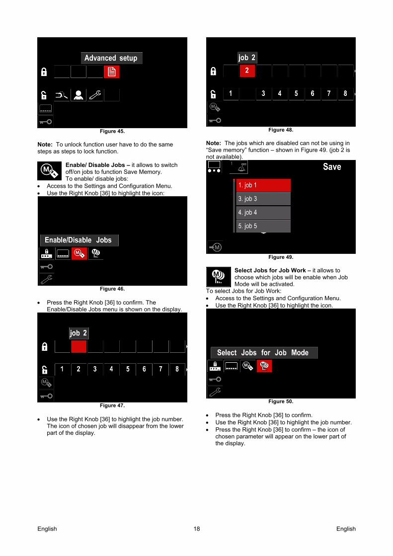
Figure 48.
Note: The jobs which are disabled can not be using in “Save memory” function – shown in Figure 49. (job 2 is not available).
Figure 49.
Select Jobs for Job Work – it allows to choose which jobs will be enable when Job Mode will be activated.
To select Jobs for Job Work: Access to the Settings and Configuration Menu. Use the Right Knob [36] to highlight the icon.
Figure 50.
Press the Right Knob [36] to confirm. Use the Right Knob [36] to highlight the job number. Press the Right Knob [36] to confirm – the icon of
chosen parameter will appear on the lower part of the display.

English 19 English
Figure 51.
Press Button [37] to return to main menu.
Job Mode – user has access to operate only with selected jobs. Note: First of all user have to select jobs
which can be used in Job Mode (Access Control -> Select Jobs for Job Work) To activate Job Mode: Access to the Settings and Configuration Menu. Use the Right Knob [36] to highlight the Job Mode
icon.
Figure 52.
Press the Right Knob [36]. The Job Mode Menu is
shown on the display. Use the Right Knob [36] to highlight one of the option
shown on the figure below. X - Cancel Job Mode - Activate Job Mode
Figure 53.
Press Right Knob [36] to confirm the selection. Note: After activated Job Mode the icon of this function will be displayed on the Welding Parameters Bar. Also the Load Memory and Save Memory options will be blocked in this mode.
Set the Language – user can choose interface language (English, Polish, Finnish, French, German, Spanish, Italian, Dutch,
Romanian). To set the language: Access to the Settings and Configuration Menu. Use the Right Knob [36] to highlight the Set the
Language icon.
Figure 54.
Press the Right Knob [36]. The Language Menu is
shown on the display.
Figure 55.
Use the Right Knob [36] to choose the Language. Confirm the select – press the Right Knob [36].
Restore Factory Settings Note: After Factory Settings restore, the settings stored in user memory are deleted.
To restore Factory Settings: Access to the Settings and Configuration Menu. Use the Right Knob [36] to highlight the Restore
Factory Settings icon.
Figure 56.
Press the Right Knob [36]. The Restore Factory
Settings Menu is shown on the display. Use the Right Knob [36] to highlight the Check Mark.
English 20 English
Figure 57.
Confirm the select – press the Right Button [36]. The
factory settings are restored.
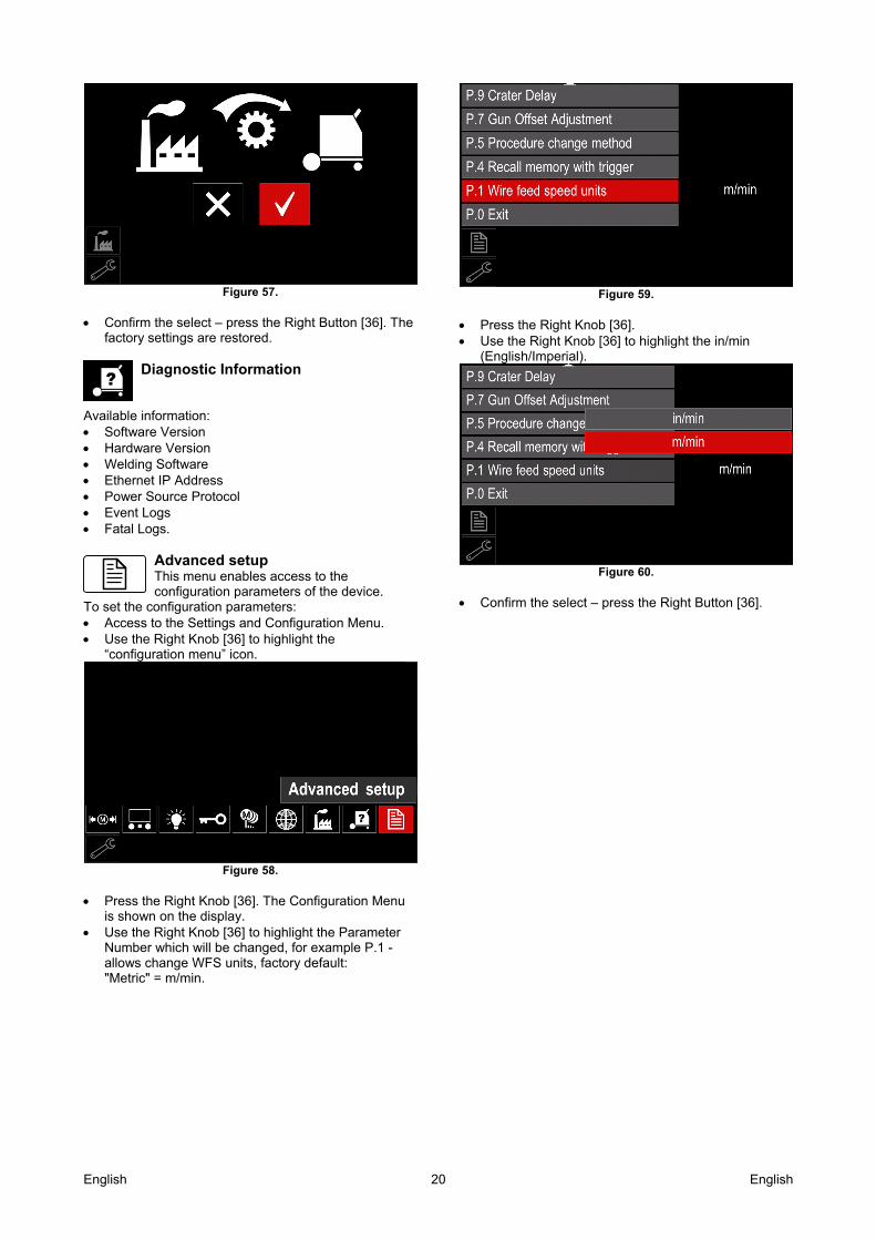
Diagnostic Information
Available information: Software Version Hardware Version Welding Software Ethernet IP Address Power Source Protocol Event Logs Fatal Logs.
Advanced setup This menu enables access to the configuration parameters of the device.
To set the configuration parameters: Access to the Settings and Configuration Menu. Use the Right Knob [36] to highlight the
“configuration menu” icon.
Figure 58.
Press the Right Knob [36]. The Configuration Menu
is shown on the display. Use the Right Knob [36] to highlight the Parameter
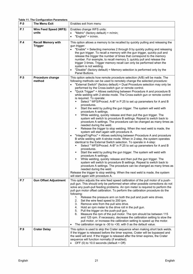
Number which will be changed, for example P.1 - allows change WFS units, factory default: "Metric" = m/min.
Figure 59.
Press the Right Knob [36]. Use the Right Knob [36] to highlight the in/min
(English/Imperial).
Figure 60.
Confirm the select – press the Right Button [36].
English 21 English
Table 11. The Configuration Parameters
P.0 The Menu Exit Enables exit from menu
P.1 Wire Feed Speed (WFS) units
Enables change WFS units: "Metric" (factory default) = m/min; "English" = in/min.
P.4 Recall Memory with Trigger
This option allows a memory to be recalled by quickly pulling and releasing the gun trigger: "Enable" = Selecting memories 2 through 9 by quickly pulling and releasing
the gun trigger. To recall a memory with the gun trigger, quickly pull and release the trigger the number of times that correspond to the memory number. For example, to recall memory 3, quickly pull and release the trigger 3 times. Trigger memory recall can only be performed when the system is not welding.
"Disable" (factory default) = Memory selection is performed only by the Panel Buttons.
P.5 Procedure change method
This option selects how remote procedure selection (A/B) will be made. The following methods can be used to remotely change the selected procedure: "External Switch" (factory default) = Dual Procedure selection may only be
performed by the Cross-switch gun or remote control. "Quick Trigger" = Allows switching between Procedure A and procedure B
while welding with 2-stroke mode. The Cross-switch gun or remote control is required. To operate: Select " WFS/Proced. A-B" in P.25 to set up parameters for A and B
procedures. Start the weld by pulling the gun trigger. The system will weld with
procedure A settings. While welding, quickly release and then pull the gun trigger. The
system will switch to procedure B settings. Repeat to switch back to procedure A settings. The procedure can be changed as many times as needed during the weld.
Release the trigger to stop welding. When the next weld is made, the system will start again with procedure A.
"IntegralTrigProc" = Allows switching between Procedure A and procedure B while welding with 4-stroke mode. When in 2-step, the system operates identical to the External Switch selection. To operate in 4-step: Select " WFS/Proced. A-B" in P.25 to set up parameters for A and B
procedures. Start the weld by pulling the gun trigger. The system will weld with
procedure A settings. While welding, quickly release and then pull the gun trigger. The
system will switch to procedure B settings. Repeat to switch back to procedure A settings. The procedure can be changed as many times as needed during the weld.
Release the trigger to stop welding. When the next weld is made, the system will start again with procedure A.
P.7 Gun Offset Adjustment This option adjusts the wire feed speed calibration of the pull motor of a push-pull gun. This should only be performed when other possible corrections do not solve any push-pull feeding problems. An rpm meter is required to perform the pull gun motor offset calibration. To perform the calibration procedure do the following:
1. Release the pressure arm on both the pull and push wire drives. 2. Set the wire feed speed to 200 ipm. 3. Remove wire from the pull wire drive. 4. Hold an rpm meter to the drive roll in the pull gun. 5. Pull the trigger on the push-pull gun. 6. Measure the rpm of the pull motor. The rpm should be between 115
and 125 rpm. If necessary, decrease the calibration setting to slow the pull motor, or increase the calibration setting to speed up the motor.
The calibration range is -30 to +30, with 0 as the default value.
P.9 Crater Delay This option is used to skip the Crater sequence when making short tack welds. If the trigger is released before the timer expires, Crater will be bypassed and the weld will end. If the trigger is released after the timer expires, the Crater sequence will function normally (if enabled). OFF (0) to 10.0 seconds (default = Off)
English 22 English
P.17 Remote Control Type This option selects the type of analog remote control being used. Digital remote control devices (those with a digital display) are configured automatically. "Push-Pull Gun" = Use this setting while MIG welding with a push-pull gun
that uses a potentiometer for wire feed speed control (this setting is backward compatible with "P.17 Gun Selection" = PushPull).
"TIG Amp Control" = Use this setting while TIG welding with a foot or hand current control device (Amptrol). While TIG welding, the upper left Control on the User Interface sets the maximum current obtained when the TIG amp control is at its maximum setting.
"Stick/Gouge Rem." = Use this setting while stick welding or gouging with a remote output control device. While stick welding, the upper left Control on the User Interface sets the maximum current obtained when the stick remote is at its maximum setting. While gouging, the upper left Control is disabled and the gouging current is set on the remote control.
"All Mode Remote" = This setting allows the remote control to function in all weld modes which is how most machines with 6-pin and 7-pin remote control connections operate.
"Joystick MIG Gun" (European default) = Use this setting while MIG welding with a push MIG gun with a joystick control. Stick, TIG and gouge welding currents are set at the User Interface. Note: On machines that do not have a 12-pin connector, the "Joystick MIG Gun" settings will not appear.
P.20 Display Trim as Volts Option
Determines how trim is displayed "No" (factory default) = The trim is displayed in the format defined in the
weld set. "Yes" = All trim values are displayed as a voltage. Note: This option may not be available on all machines. The power source must support this functionality, or this option will not appear in the menu.
P.22 Arc Start/Loss Error Time
This option can be used to optionally shut off output if an arc is not established, or is lost for a specified amount of time. Error 269 will be displayed if the machine times out. If the value is set to OFF, machine output will not be turned off if an arc is not established nor will output be turned off if an arc is lost. The trigger can be used to hot feed the wire (default). If a value is set, the machine output will shut off if an arc is not established within the specified amount of time after the trigger is pulled or if the trigger remains pulled after an arc is lost. To prevent nuisance errors, set Arc Start/Loss Error Time to an appropriate value after considering all welding parameters (run-in wire feed speed, weld wire feed speed, electrical stick out, etc.). To prevent subsequent changes to Arc Start/Loss Error Time, the setup menu should be locked out by setting Preference Lock = Yes using the Power Wave Manager software. Note: This parameter is disabled while welding in Stick, TIG or Gouge.
P.25 Joystick Configuration This option can be used to change the behavior of the left and right joystick positions: "Disable Joystick" = The joystick does not function. "WFS/Trim" = The left and right joystick positions will adjust Arc Length
Trim, Arc Voltage, Power or STT® Background Current based on the selected weld mode. For example, when a non-synergic STT® weld mode is selected, the left and right joystick positions will adjust Background Current. When a Power mode is selected, the left and right joystick positions will adjust the Power (kW).
"WFS/Job"(memory) = The left and right joystick positions will: Select a user memory while not welding. Adjust Trim/Voltage/Power/STT Background Current while welding.
"WFS/Proced. A-B" = The left and right joystick positions will be used to select procedure A and B, while welding and while not welding. The left joystick position selects procedure A, the right joystick position selects procedure B.
Note: In all configurations other than "Disable Joystick", the up and down joystick positions will adjust the wire feed speed, while welding and while not welding.
P.28 Display Workpoint as Amps Option
Determines how workpoint is displayed: "No" (factory default) = The workpoint is displayed in the format defined in
the weld set. "Yes" = All workpoint values are displayed as an amperage. Note: This option may not be available on all machines. The power source must support this functionality, or this option will not appear in the menu

English 23 English
P.80 Sense From Studs Use this option for diagnostic purposes only. When power is cycled, this option is automatically reset to False. "False" (default) = Voltage sensing is automatically determined by the
selected weld mode and other machine settings. "True" = Voltage sensing is forced to "studs" of the power source.
P.81 Electrode Polarity Used in place of DIP switches for configuration of the work and electrode sense leads "Positive" (default) = Most GMAW welding procedures use Electrode
Positive welding. "Negative" = Most GTAW and some inner shield procedures use Electrode
Negative welding.
P.99 Show Test Modes Uses for calibration and tests. "No" (factory default) = Turned off; "Yes" = Allows to selection test modes. Note: After the device has been restarted the P.99 is "NO".
P.323 System Update This parameter is active only when the USB Memory Stick (with upgrade file) is connected to USB socket. Cancel – goes back to Configuration Parameters menu Accept – starts updating process
English 24 English
Cooler menu
WARNING Cooler Menu is available when cooler is connected.
Figure 61.
Table 12. Cooler Menu
Symbol Description
Settings
Filling
Settings of the cooler – This function allows following cooler modes:
Table 13. Settings of the cooler modes
Symbol Description
Automatic
Off
On
Refer cooler instruction manual for more details.
Service Menu It allows the access to special service functions.
WARNING Service Menu is available when USB storage device is connected.
Figure 62.
Table 14. Service Menu
Symbol Description
Service weld logs
Weld History
SnapShot
Service weld logs – allows recording welding parameters which were using during the welding.
To access the menu: Make sure that USB device is connected to welding
machine Access to the Settings and Configuration Menu. Use the Right Knob [36] to highlight the Service
Menu icon Press the Right Knob [36] – the recording process
will started.
Figure 63.
Press the Right Knob [36] to continue.
Figure 64.
English 25 English
Press the Left Knob [35] or Button [37] to exit Recording icon will appear on the Status
bar [38]. Note: To stop the recording go to Service Menu and press the Service weld logs icon again
Weld history – after recording, welding parameters are saved into the USB device folder.To access the Welding history:
Make sure that USB device is connected. Access to the Settings and Configuration Menu. Go to Service Menu → Weld History
Figure 65.
Press the Right Knob [36] to get access of Weld
history – the list of used parameters: - Weld number - Average WFS - Average current [A] - Average voltage [V] - Arc time [s] - Welding program number - Job number/name
SnapShot - create a file that contains detailed configuration and debugging information collected from each module in the Powertec i380C Advanced.
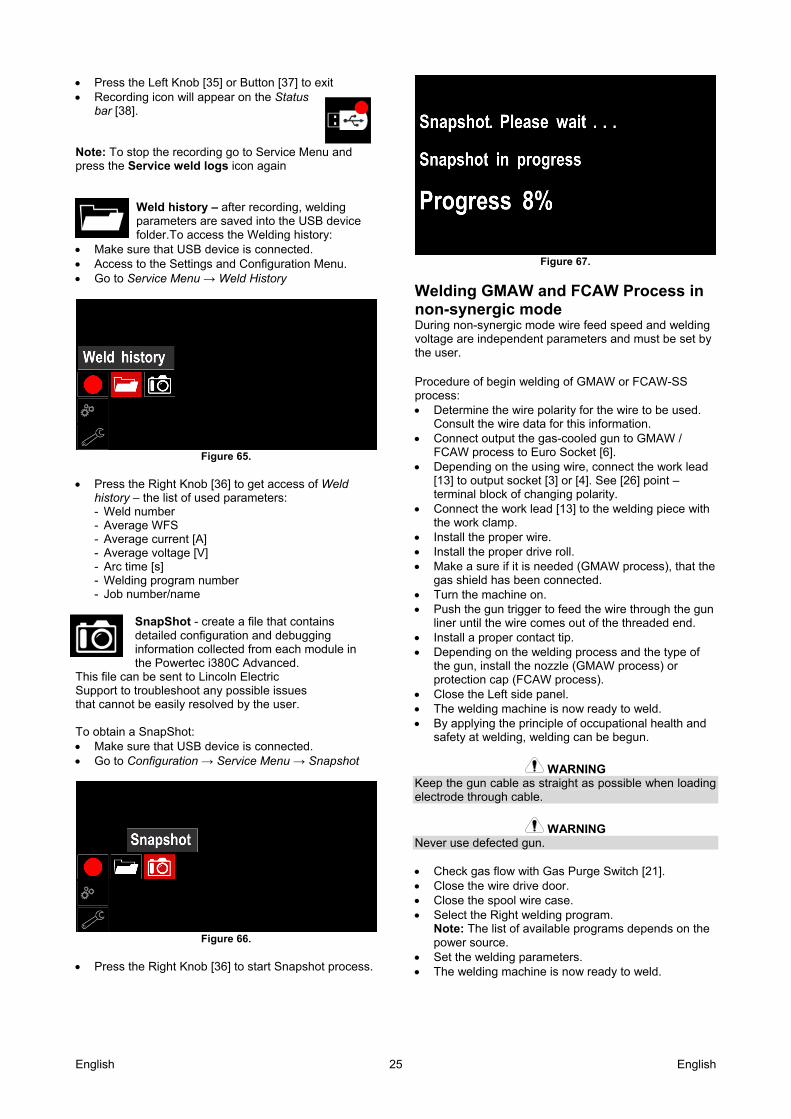
This file can be sent to Lincoln Electric Support to troubleshoot any possible issues that cannot be easily resolved by the user. To obtain a SnapShot: Make sure that USB device is connected. Go to Configuration → Service Menu → Snapshot
Figure 66.
Press the Right Knob [36] to start Snapshot process.
Figure 67.
Welding GMAW and FCAW Process in non-synergic mode During non-synergic mode wire feed speed and welding voltage are independent parameters and must be set by the user. Procedure of begin welding of GMAW or FCAW-SS process: Determine the wire polarity for the wire to be used.
Consult the wire data for this information. Connect output the gas-cooled gun to GMAW /
FCAW process to Euro Socket [6]. Depending on the using wire, connect the work lead
[13] to output socket [3] or [4]. See [26] point – terminal block of changing polarity.
Connect the work lead [13] to the welding piece with the work clamp.
Install the proper wire. Install the proper drive roll. Make a sure if it is needed (GMAW process), that the
gas shield has been connected. Turn the machine on. Push the gun trigger to feed the wire through the gun
liner until the wire comes out of the threaded end. Install a proper contact tip. Depending on the welding process and the type of
the gun, install the nozzle (GMAW process) or protection cap (FCAW process).
Close the Left side panel. The welding machine is now ready to weld. By applying the principle of occupational health and
safety at welding, welding can be begun.
WARNING Keep the gun cable as straight as possible when loading electrode through cable.
WARNING Never use defected gun. Check gas flow with Gas Purge Switch [21]. Close the wire drive door. Close the spool wire case. Select the Right welding program.
Note: The list of available programs depends on the power source.
Set the welding parameters. The welding machine is now ready to weld.
English 26 English
WARNING The wire drive door and wire spool case have to be completely closed during welding.
WARNING Keep the gun cable as straight as possible when welding or loading electrode through cable.
WARNING Do not kink or pull cable around sharp corners. By applying the principle of occupational health and
safety at welding, welding can be begun. For non-synergic mode can set: Wire Feed Speed, WFS The welding voltage Burnback Time Run-in WFS Preflow Time/ Postflow Time Spot Time 2-Step/4-Step Start Procedure Crater Procedure Wave Control:
Pinch
Welding GMAW and FCAW Process in synergic mode CV In synergic mode, the welding voltage is not set by user. The correct welding voltage will set by the machine’s software. This value was recalled on the basis of data (input data) had been loaded: Wire Feed Speed, WFS. If it is needed, the welding voltage can be adjusted by the Right Control [36]. When the Right Control is rotated, the display will show a positive or negative bar indicates if the voltage is above or below the ideal voltage. Additionally can manually set: Burnback Run-In WFS Preflow Time/ Postflow Time Spot Time 2-Step/4-Step Start Procedure Crater Procedure Wave Control:
Pinch
Welding SMAW Process POWERTEC i380 ADVANCED does not include the electrode holder with lead necessary for SMAW welding, but the one can be purchased separately. Procedure of begin welding of SMAW process: First turn the machine off. Determine the electrode polarity for the electrode to
be used. Consult the electrode data for this information.
Depending on the polarity of using electrode, connect the work lead [13] and the electrode holder with lead to output socket [3] or [4] and lock them. See the Table 15.
Table 15. Polarity
Output Socket
PO
LA
RIT
Y
DC
(+
) The electrode holder with lead to SMAW
[4]
Work lead [3]
DC
(+
)
The electrode holder with lead to SMAW
[3]
Work lead [4]
Connect the work lead to the welding piece with the
work clamp. Install the proper electrode in the electrode holder. Turn the input power ON. Set the SMAW welding program. Set the welding parameters. The welding machine is now ready to weld. By applying the principle of occupational health and
safety at welding, welding can be begun. For SMAW program can set: Welding current Switch on / switch off the output voltage on the
output lead Wave Controls:
ARC FORCE HOT START
Loading the Electrode Wire Turn the machine off. Open the Right panel of the machine. Unscrew the locking nut of the sleeve. Load the spool with the wire on the sleeve such that
the spool turns anticlockwise when the wire is fed into the wire feeder.
Make sure that the spool locating pin goes into the fitting hole on the spool.
Screw in the fastening cap of the sleeve. Put on the wire roll using the correct groove
corresponding to the wire diameter. Free the end of the wire and cut off the bent end
making sure it has no burr.
WARNING Sharp end of the wire can hurt. Rotate the wire spool anticlockwise and thread the
end of the wire into the wire feeder as far as the Euro socket.
Adjust force of pressure roll of the wire feeder properly.
Adjustments of Brake Torque of Sleeve To avoid spontaneous unrolling of the welding wire the sleeve is fitted with a brake. Adjustment is carried by rotation of its Allen screw M8, which is placed inside of the sleeve frame after unscrewing the fastening cap of the sleeve.
English 27 English
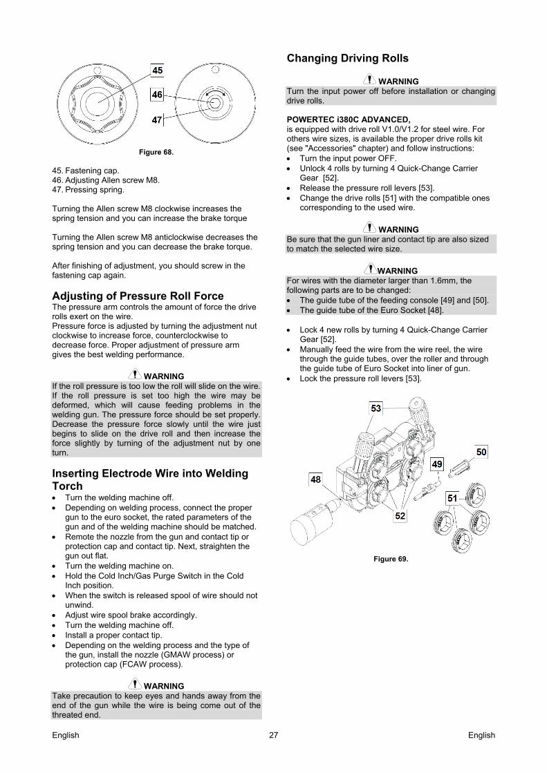
Figure 68.
45. Fastening cap. 46. Adjusting Allen screw M8. 47. Pressing spring. Turning the Allen screw M8 clockwise increases the spring tension and you can increase the brake torque Turning the Allen screw M8 anticlockwise decreases the spring tension and you can decrease the brake torque. After finishing of adjustment, you should screw in the fastening cap again.
Adjusting of Pressure Roll Force The pressure arm controls the amount of force the drive rolls exert on the wire. Pressure force is adjusted by turning the adjustment nut clockwise to increase force, counterclockwise to decrease force. Proper adjustment of pressure arm gives the best welding performance.
WARNING If the roll pressure is too low the roll will slide on the wire. If the roll pressure is set too high the wire may be deformed, which will cause feeding problems in the welding gun. The pressure force should be set properly. Decrease the pressure force slowly until the wire just begins to slide on the drive roll and then increase the force slightly by turning of the adjustment nut by one turn.
Inserting Electrode Wire into Welding Torch Turn the welding machine off. Depending on welding process, connect the proper
gun to the euro socket, the rated parameters of the gun and of the welding machine should be matched.
Remote the nozzle from the gun and contact tip or protection cap and contact tip. Next, straighten the gun out flat.
Turn the welding machine on. Hold the Cold Inch/Gas Purge Switch in the Cold
Inch position. When the switch is released spool of wire should not
unwind. Adjust wire spool brake accordingly. Turn the welding machine off. Install a proper contact tip. Depending on the welding process and the type of
the gun, install the nozzle (GMAW process) or protection cap (FCAW process).
WARNING Take precaution to keep eyes and hands away from the end of the gun while the wire is being come out of the threated end.
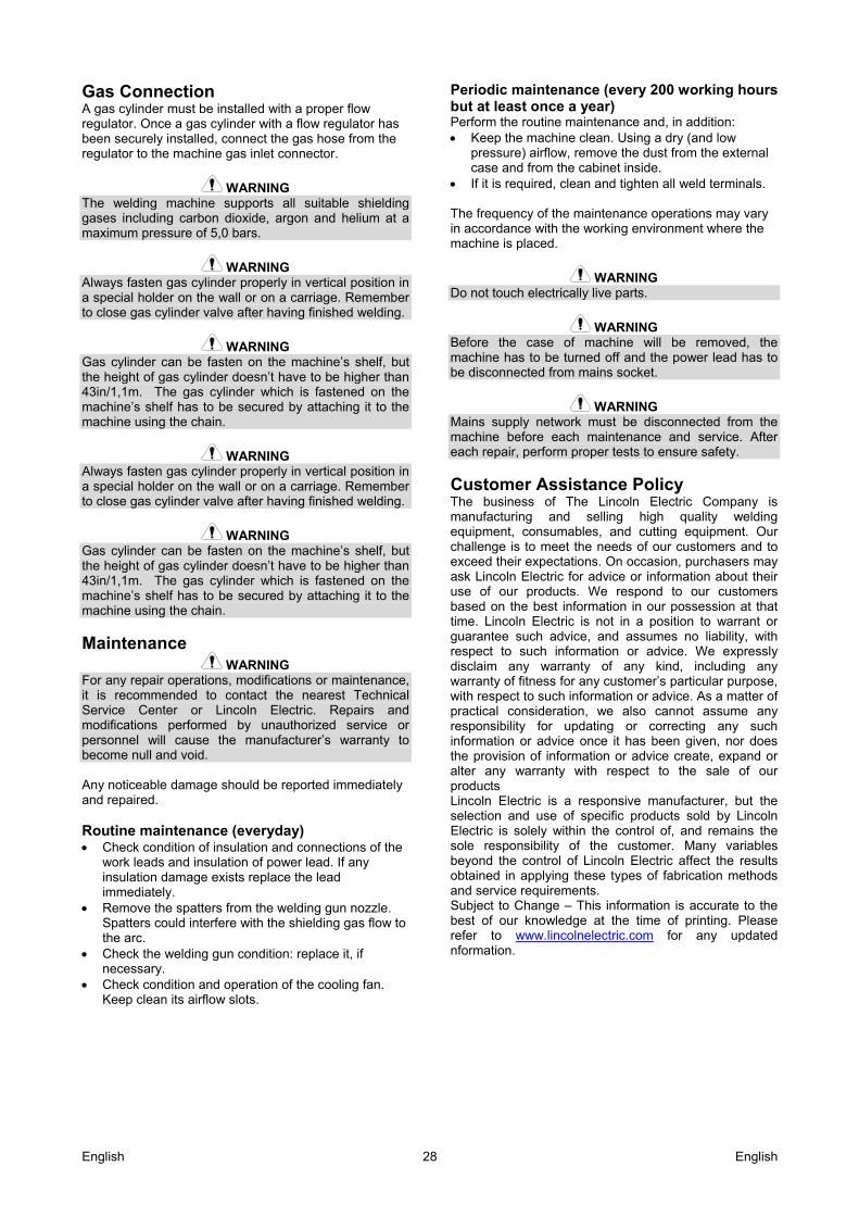
Changing Driving Rolls
WARNING Turn the input power off before installation or changing drive rolls. POWERTEC i380C ADVANCED, is equipped with drive roll V1.0/V1.2 for steel wire. For others wire sizes, is available the proper drive rolls kit (see "Accessories" chapter) and follow instructions: Turn the input power OFF. Unlock 4 rolls by turning 4 Quick-Change Carrier
Gear [52]. Release the pressure roll levers [53]. Change the drive rolls [51] with the compatible ones
corresponding to the used wire.
WARNING Be sure that the gun liner and contact tip are also sized to match the selected wire size.
WARNING For wires with the diameter larger than 1.6mm, the following parts are to be changed: The guide tube of the feeding console [49] and [50]. The guide tube of the Euro Socket [48]. Lock 4 new rolls by turning 4 Quick-Change Carrier
Gear [52]. Manually feed the wire from the wire reel, the wire
through the guide tubes, over the roller and through the guide tube of Euro Socket into liner of gun.
Lock the pressure roll levers [53].
Figure 69.
English 28 English
Gas Connection A gas cylinder must be installed with a proper flow regulator. Once a gas cylinder with a flow regulator has been securely installed, connect the gas hose from the regulator to the machine gas inlet connector.
WARNING The welding machine supports all suitable shielding gases including carbon dioxide, argon and helium at a maximum pressure of 5,0 bars.
WARNING Always fasten gas cylinder properly in vertical position in a special holder on the wall or on a carriage. Remember to close gas cylinder valve after having finished welding.
WARNING Gas cylinder can be fasten on the machine’s shelf, but the height of gas cylinder doesn’t have to be higher than 43in/1,1m. The gas cylinder which is fastened on the machine’s shelf has to be secured by attaching it to the machine using the chain.
Maintenance WARNING
For any repair operations, modifications or maintenance, it is recommended to contact the nearest Technical Service Center or Lincoln Electric. Repairs and modifications performed by unauthorized service or personnel will cause the manufacturer’s warranty to become null and void. Any noticeable damage should be reported immediately and repaired. Routine maintenance (everyday) Check condition of insulation and connections of the
work leads and insulation of power lead. If any insulation damage exists replace the lead immediately.
Remove the spatters from the welding gun nozzle. Spatters could interfere with the shielding gas flow to the arc.
Check the welding gun condition: replace it, if necessary.
Check condition and operation of the cooling fan. Keep clean its airflow slots.
Periodic maintenance (every 200 working hours but at least once a year) Perform the routine maintenance and, in addition: Keep the machine clean. Using a dry (and low
pressure) airflow, remove the dust from the external case and from the cabinet inside.
If it is required, clean and tighten all weld terminals. The frequency of the maintenance operations may vary in accordance with the working environment where the machine is placed.
WARNING Do not touch electrically live parts.
WARNING Before the case of machine will be removed, the machine has to be turned off and the power lead has to be disconnected from mains socket.
WARNING Mains supply network must be disconnected from the machine before each maintenance and service. After each repair, perform proper tests to ensure safety.
Customer Assistance Policy The business of The Lincoln Electric Company is manufacturing and selling high quality welding equipment, consumables, and cutting equipment. Our challenge is to meet the needs of our customers and to exceed their expectations. On occasion, purchasers may ask Lincoln Electric for advice or information about their use of our products. We respond to our customers based on the best information in our possession at that time. Lincoln Electric is not in a position to warrant or guarantee such advice, and assumes no liability, with respect to such information or advice. We expressly disclaim any warranty of any kind, including any warranty of fitness for any customer’s particular purpose, with respect to such information or advice. As a matter of practical consideration, we also cannot assume any responsibility for updating or correcting any such information or advice once it has been given, nor does the provision of information or advice create, expand or alter any warranty with respect to the sale of our products Lincoln Electric is a responsive manufacturer, but the selection and use of specific products sold by Lincoln Electric is solely within the control of, and remains the sole responsibility of the customer. Many variables beyond the control of Lincoln Electric affect the results obtained in applying these types of fabrication methods and service requirements. Subject to Change – This information is accurate to the best of our knowledge at the time of printing. Please refer to www.lincolnelectric.com for any updated nformation.

English 29 English
WEEE 07/06
En
gli
sh
Do not dispose of electrical equipment together with normal waste! In observance of European Directive 2012/19/EC on Waste Electrical and Electronic Equipment (WEEE) and its implementation in accordance with national law, electrical equipment that has reached the end of its life must be collected separately and returned to an environmentally compatible recycling facility. As the owner of the equipment, you should get information on approved collection systems from our local representative. By applying this European Directive you will protect the environment and human health!
Spare Parts 12/05
Part List reading instructions Do not use this part list for a machine if its code number is not listed. Contact the Lincoln Electric Service
Department for any code number not listed. Use the illustration of assembly page and the table below to determine where the part is located for your particular
code machine. Use only the parts marked "X" in the column under the heading number called for in the assembly page (# indicate
a change in this printing).
First, read the Part List reading instructions above, then refer to the "Spare Part" manual supplied with the machine, that contains a picture-descriptive part number cross-reference.
Authorized Service Shops Location 09/16
The purchaser must contact a Lincoln Authorized Service Facility (LASF) about any defect claimed under Lincoln's warranty period.
Contact your local Lincoln Sales Representative for assistance in locating a LASF or go to www.lincolnelectric.com/en-gb/Support/Locator.
Electrical Schematic Refer to the "Spare Part" manual supplied with the machine.
English 30 English
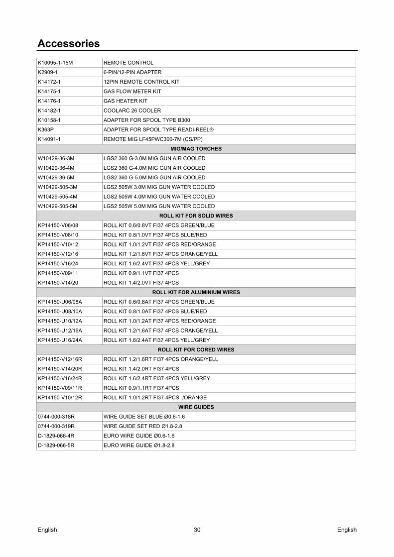
Accessories K10095-1-15M REMOTE CONTROL
K2909-1 6-PIN/12-PIN ADAPTER
K14172-1 12PIN REMOTE CONTROL KIT
K14175-1 GAS FLOW METER KIT
K14176-1 GAS HEATER KIT
K14182-1 COOLARC 26 COOLER
K10158-1 ADAPTER FOR SPOOL TYPE B300
K363P ADAPTER FOR SPOOL TYPE READI-REEL®
K14091-1 REMOTE MIG LF45PWC300-7M (CS/PP)
MIG/MAG TORCHES
W10429-36-3M LGS2 360 G-3.0M MIG GUN AIR COOLED
W10429-36-4M LGS2 360 G-4.0M MIG GUN AIR COOLED
W10429-36-5M LGS2 360 G-5.0M MIG GUN AIR COOLED
W10429-505-3M LGS2 505W 3.0M MIG GUN WATER COOLED
W10429-505-4M LGS2 505W 4.0M MIG GUN WATER COOLED
W10429-505-5M LGS2 505W 5.0M MIG GUN WATER COOLED
ROLL KIT FOR SOLID WIRES
KP14150-V06/08 ROLL KIT 0.6/0.8VT FI37 4PCS GREEN/BLUE
KP14150-V08/10 ROLL KIT 0.8/1.0VT FI37 4PCS BLUE/RED
KP14150-V10/12 ROLL KIT 1.0/1.2VT FI37 4PCS RED/ORANGE
KP14150-V12/16 ROLL KIT 1.2/1.6VT FI37 4PCS ORANGE/YELL
KP14150-V16/24 ROLL KIT 1.6/2.4VT FI37 4PCS YELL/GREY
KP14150-V09/11 ROLL KIT 0.9/1.1VT FI37 4PCS
KP14150-V14/20 ROLL KIT 1.4/2.0VT FI37 4PCS
ROLL KIT FOR ALUMINIUM WIRES
KP14150-U06/08A ROLL KIT 0.6/0.8AT FI37 4PCS GREEN/BLUE
KP14150-U08/10A ROLL KIT 0.8/1.0AT FI37 4PCS BLUE/RED
KP14150-U10/12A ROLL KIT 1.0/1.2AT FI37 4PCS RED/ORANGE
KP14150-U12/16A ROLL KIT 1.2/1.6AT FI37 4PCS ORANGE/YELL
KP14150-U16/24A ROLL KIT 1.6/2.4AT FI37 4PCS YELL/GREY
ROLL KIT FOR CORED WIRES
KP14150-V12/16R ROLL KIT 1.2/1.6RT FI37 4PCS ORANGE/YELL
KP14150-V14/20R ROLL KIT 1.4/2.0RT FI37 4PCS
KP14150-V16/24R ROLL KIT 1.6/2.4RT FI37 4PCS YELL/GREY
KP14150-V09/11R ROLL KIT 0.9/1.1RT FI37 4PCS
KP14150-V10/12R ROLL KIT 1.0/1.2RT FI37 4PCS -/ORANGE
WIRE GUIDES
0744-000-318R WIRE GUIDE SET BLUE Ø0.6-1.6
0744-000-319R WIRE GUIDE SET RED Ø1.8-2.8
D-1829-066-4R EURO WIRE GUIDE Ø0.6-1.6
D-1829-066-5R EURO WIRE GUIDE Ø1.8-2.8