Embed Size (px)
Citation preview
RETRACTABLE AWNINGSFor Technical Support visit us at www.sunsetter.com/ownerscorner
or Call Toll Free 800-670-7071 • Fax 877-224-4944
©SunSetter Products, a Massachusetts Limited Partnership, 184 Charles Street, Malden, MA 02148
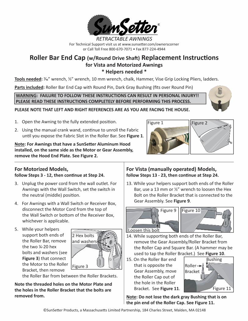
Roller Bar End Cap (w/Round Drive Shaft) Replacement Instructions for Vista and Motorized Awnings
* Helpers needed *Tools needed: 7/16” wrench, 1/2” wrench, 10 mm wrench, chalk, Hammer, Vise Grip Locking Pliers, ladders.
Parts included: Roller Bar End Cap with Round Pin, Dark Gray Bushing (fits over Round Pin)
WARNING: FAILURE TO FOLLOW THESE INSTRUCTIONS CAN RESULT IN PERSONAL INJURY!! PLEASE READ THESE INSTRUCTIONS COMPLETELY BEFORE PERFORMING THIS PROCESS.
PLEASE NOTE THAT LEFT AND RIGHT REFERENCES ARE AS YOU ARE FACING THE HOUSE.
1. Open the Awning to the fully extended position.
2. Using the manual crank wand, continue to unroll the Fabric until you expose the Fabric Slot in the Roller Bar. See Figure 1.
Note: For Awnings that have a SunSetter Aluminum Hood installed, on the same side as the Motor or Gear Assembly, remove the Hood End Plate. See Figure 2.
For Motorized Models, follow Steps 3 - 12, then continue at Step 24.
3. Unplug the power cord from the wall outlet. For Awnings with the Wall Switch, set the switch in the neutral (middle) position.
4. For Awnings with a Wall Switch or Receiver Box, disconnect the Motor Cord from the top of the Wall Switch or bottom of the Receiver Box, whichever is applicable.
5. While your helpers support both ends of the Roller Bar, remove the two ¼-20 hex bolts and washers (see Figure 3) that connect the Motor to the Roller Bracket, then remove the Roller Bar from between the Roller Brackets.
Note the threaded holes on the Motor Plate and the holes in the Roller Bracket that the bolts are removed from.
For Vista (manually operated) Models, follow Steps 13 - 23, then continue at Step 24.
13. While your helpers support both ends of the Roller Bar, use a 13 mm or 1/2” wrench to loosen the Hex Bolt on the Roller Bracket that is connected to the Gear Assembly. See Figure 9.
14. While supporting both ends of the Roller Bar, remove the Gear Assembly/Roller Bracket from the Roller Cap and Square Bar. (A hammer may be used to tap the Roller Bracket.) See Figure 10.
Roller Bracket
Bushing15. On the Roller Bar end that is opposite the Gear Assembly, move the Roller Cap out of the hole in the Roller Bracket. See Figure 11.
Note: Do not lose the dark gray Bushing that is on the pin end of the Roller Cap. See Figure 11.
Figure 1 Figure 2
Figure 3
2 Hex bolts and washers
Figure 9 Figure 10
Figure 11
Loosen this bolt
2
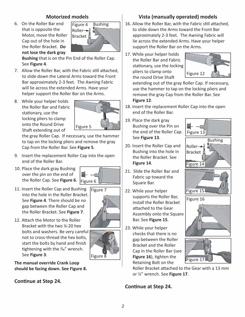
6. On the Roller Bar end that is opposite the Motor, move the Roller Cap out of the hole in the Roller Bracket. Do not lose the dark gray Bushing that is on the Pin End of the Roller Cap. See Figure 4.
16. Allow the Roller Bar, with the Fabric still attached, to slide down the Arms toward the Front Bar approximately 2-3 feet. The Awning Fabric will lie across the extended Arms. Have your helper support the Roller Bar on the Arms.
7. Allow the Roller Bar, with the Fabric still attached, to slide down the Lateral Arms toward the Front Bar approximately 2-3 feet. The Awning Fabric will lie across the extended Arms. Have your helper support the Roller Bar on the Arms.
Roller Bracket
Bushing
8. While your helper holds the Roller Bar and Fabric stationary, use the locking pliers to clamp onto the Round Drive Shaft extending out of the gray Roller Cap. If necessary, use the hammer to tap on the locking pliers and remove the gray Cap from the Roller Bar. See Figure 5.
9. Insert the replacement Roller Cap into the open end of the Roller Bar.
10. Place the dark gray Bushing over the pin on the end of the Roller Cap. See Figure 6.
11. Insert the Roller Cap and Bushing into the hole in the Roller Bracket. See Figure 4. There should be no gap between the Roller Cap and the Roller Bracket. See Figure 7.
12. Attach the Motor to the Roller Bracket with the two ¼-20 hex bolts and washers. Be very careful not to cross-thread the hex bolts, start the bolts by hand and finish tightening with the 7/16” wrench. See Figure 3.
The manual override Crank Loop should be facing down. See Figure 8.
Continue at Step 24.
Motorized models Vista (manually operated) models
17. While your helper holds the Roller Bar and Fabric stationary, use the locking pliers to clamp onto the round Drive Shaft extending out of the gray Roller Cap. If necessary, use the hammer to tap on the locking pliers and remove the gray Cap from the Roller Bar. See Figure 12.
18. Insert the replacement Roller Cap into the open end of the Roller Bar.
19. Place the dark gray Bushing over the Pin on the end of the Roller Cap. See Figure 13.
20. Insert the Roller Cap and Bushing into the hole in the Roller Bracket. See Figure 14.
21. Slide the Roller Bar and Fabric up toward the Square Bar.
22. While your helper supports the Roller Bar, install the Roller Bracket attached to the Gear Assembly onto the Square Bar. See Figure 15.
23. While your helper checks that there is no gap between the Roller Bracket and the Roller Cap in the Roller Bar (see Figure 16), tighten the Retaining Bolt on the Roller Bracket attached to the Gear with a 13 mm or ½” wrench. See Figure 17.
Continue at Step 24.
Roller Bracket
Bushing
Figure 4
Figure 5
Figure 6
Figure 8
Figure 12
Figure 13
Figure 14
Figure 15
Figure 17
Figure 7
Figure 16
3
Continue here for all models:
24. Center the Fabric on the Front Bar and Roller Bar.
25. While keeping the Fabric reasonably stretched on the Roller Bar, use the manual Crank Wand to slowly roll the Fabric onto the Roller Bar, until both Arms start to close.
26. Reinstall the Hood End Plate, if removed. See Figure 2.
27. If applicable: reconnect the Motor Cable to the Wall Switch or Receiver Box and make sure that the Wall Switch is set in the neutral (middle) position.
28. Plug the power cord back into the wall outlet.
29. Test the Awning for proper operation.
Note: IF NEEDED, reset the motor stops using the supplied instructions.
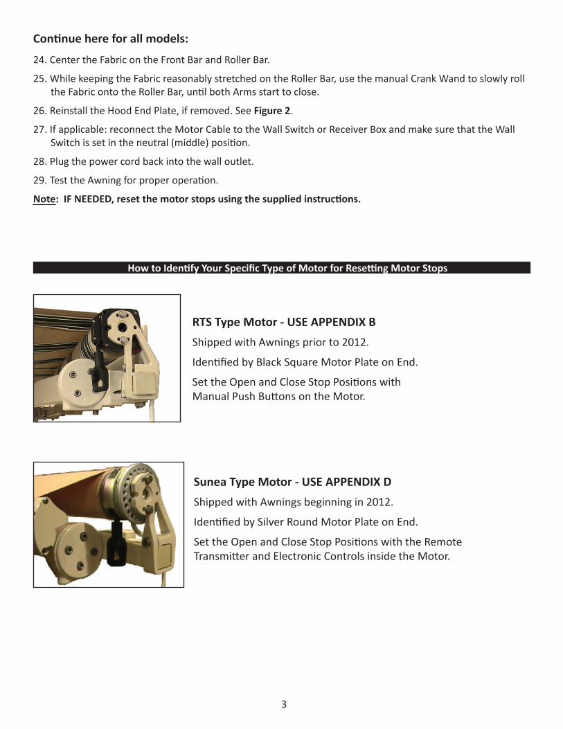
RTS Type Motor - USE APPENDIX BShipped with Awnings prior to 2012.
Identified by Black Square Motor Plate on End.
Set the Open and Close Stop Positions with Manual Push Buttons on the Motor.
Sunea Type Motor - USE APPENDIX DShipped with Awnings beginning in 2012.
Identified by Silver Round Motor Plate on End.
Set the Open and Close Stop Positions with the Remote Transmitter and Electronic Controls inside the Motor.
How to Identify Your Specific Type of Motor for Resetting Motor Stops
17
RESETTING THE LIMIT PUSH BUTTONSOF THE SUNSETTER MOTOR
Awnings with Motors installed on the Right as you face the house
APPENDIX B
2. Press the Neutral/Stop button on the remote.
3. Unplug the power cord from the electrical outlet on thewall.
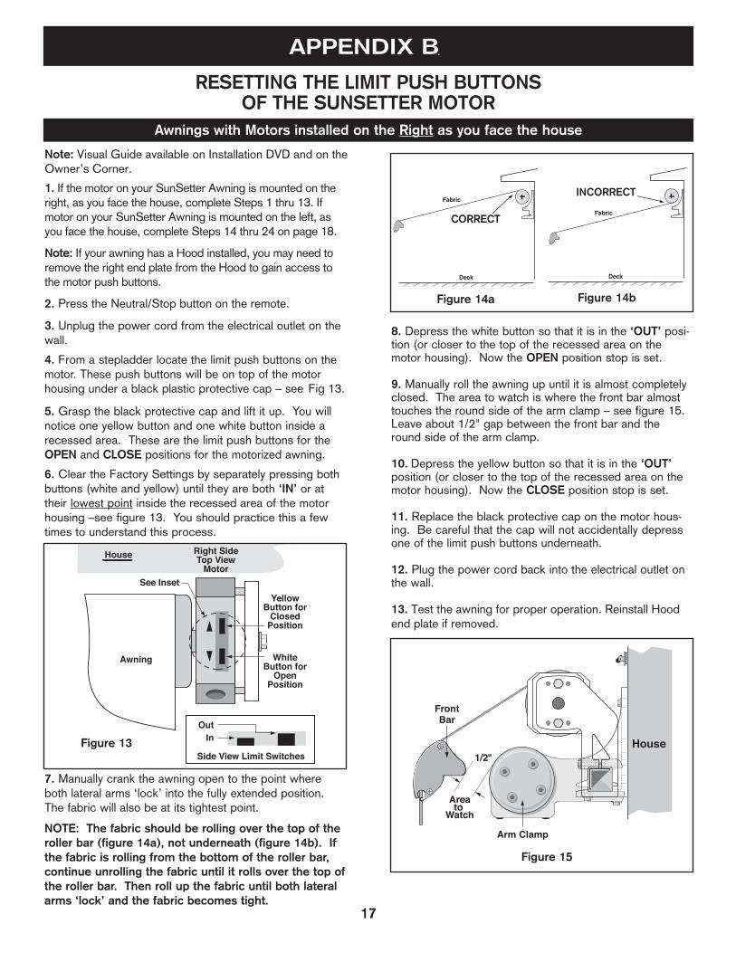
4. From a stepladder locate the limit push buttons on themotor. These push buttons will be on top of the motorhousing under a black plastic protective cap – see Fig 13.
5. Grasp the black protective cap and lift it up. You willnotice one yellow button and one white button inside arecessed area. These are the limit push buttons for theOPEN and CLOSE positions for the motorized awning.
6. Clear the Factory Settings by separately pressing bothbuttons (white and yellow) until they are both ‘IN’ or attheir lowest point inside the recessed area of the motorhousing –see figure 13. You should practice this a fewtimes to understand this process.
7. Manually crank the awning open to the point whereboth lateral arms ‘lock’ into the fully extended position.The fabric will also be at its tightest point.
NOTE: The fabric should be rolling over the top of theroller bar (figure 14a), not underneath (figure 14b). Ifthe fabric is rolling from the bottom of the roller bar,continue unrolling the fabric until it rolls over the top ofthe roller bar. Then roll up the fabric until both lateralarms ‘lock’ and the fabric becomes tight.
8. Depress the white button so that it is in the ‘OUT’ posi-tion (or closer to the top of the recessed area on themotor housing). Now the OPEN position stop is set.
9. Manually roll the awning up until it is almost completelyclosed. The area to watch is where the front bar almosttouches the round side of the arm clamp – see figure 15.Leave about 1/2" gap between the front bar and theround side of the arm clamp.
10. Depress the yellow button so that it is in the ‘OUT’position (or closer to the top of the recessed area on themotor housing). Now the CLOSE position stop is set.
11. Replace the black protective cap on the motor hous-ing. Be careful that the cap will not accidentally depressone of the limit push buttons underneath.
12. Plug the power cord back into the electrical outlet onthe wall.
13. Test the awning for proper operation. Reinstall Hood end plate if removed.
House Right SideTop View
Motor
Side View Limit Switches
Awning
See InsetYellow
Button forClosed
Position
WhiteButton for
OpenPosition
OutIn
Deck
Fabric
House
Arm Clamp
Areato
Watch
FrontBar
1/2"
Deck
Fabric
Figure 14a Figure 14b
CORRECT
INCORRECT
Figure 15
Figure 13
Note: Visual Guide available on Installation DVD and on the Owner’s Corner.
1. If the motor on your SunSetter Awning is mounted on the right, as you face the house, complete Steps 1 thru 13. If motor on your SunSetter Awning is mounted on the left, as you face the house, complete Steps 14 thru 24 on page 18.
Note: If your awning has a Hood installed, you may need to remove the right end plate from the Hood to gain access to the motor push buttons.
18
HouseLeft SideBottom View
Motor
Side View Limit Switches
Awning
Roller
See InsetYellow
Button forOpen
Position
WhiteButton for
ClosedPosition
OutIn
House
Arm Clamp
Areato
Watch
1/2"
FrontBar
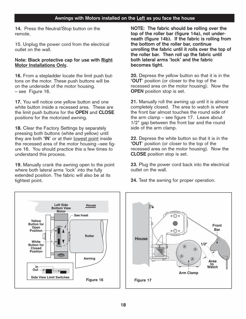
Figure 16 Figure 17
14. Press the Neutral/Stop button on the remote.
15. Unplug the power cord from the electricaloutlet on the wall.
Note: Black protective cap for use with RightMotor Installations Only.
16. From a stepladder locate the limit push but-tons on the motor. These push buttons will beon the underside of the motor housing.– see Figure 16.
17. You will notice one yellow button and onewhite button inside a recessed area. These arethe limit push buttons for the OPEN and CLOSEpositions for the motorized awning.
18. Clear the Factory Settings by separatelypressing both buttons (white and yellow) untilthey are both ‘IN’ or at their lowest point insidethe recessed area of the motor housing –see fig-ure 16. You should practice this a few times tounderstand this process.
19. Manually crank the awning open to the pointwhere both lateral arms ‘lock’ into the fullyextended position. The fabric will also be at itstightest point.
NOTE: The fabric should be rolling over thetop of the roller bar (figure 14a), not under-neath (figure 14b). If the fabric is rolling fromthe bottom of the roller bar, continueunrolling the fabric until it rolls over the top ofthe roller bar. Then roll up the fabric untilboth lateral arms ‘lock’ and the fabricbecomes tight.
20. Depress the yellow button so that it is in the‘OUT’ position (or closer to the top of therecessed area on the motor housing). Now theOPEN position stop is set.
21. Manually roll the awning up until it is almostcompletely closed. The area to watch is wherethe front bar almost touches the round side ofthe arm clamp – see figure 17. Leave about1/2" gap between the front bar and the roundside of the arm clamp.
22. Depress the white button so that it is in the‘OUT’ position (or closer to the top of therecessed area on the motor housing). Now theCLOSE position stop is set.
23. Plug the power cord back into the electricaloutlet on the wall.
24. Test the awning for proper operation.
Awnings with Motors installed on the Left as you face the house
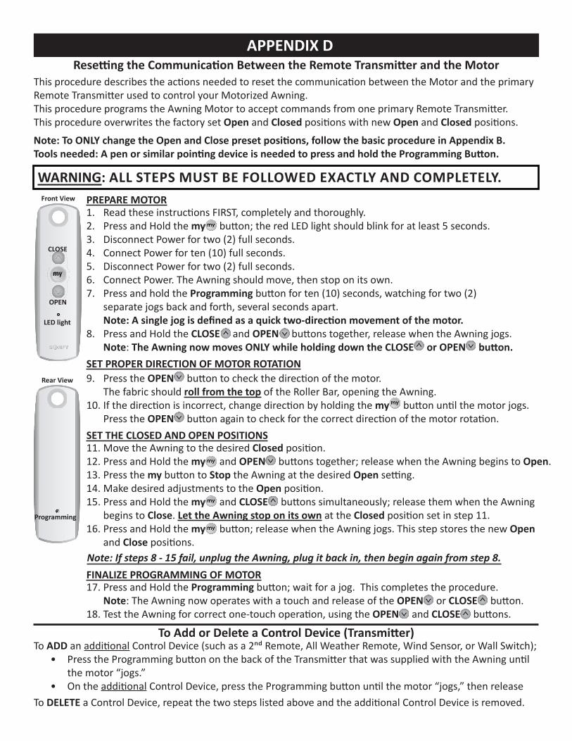
APPENDIX DResetting the Communication Between the Remote Transmitter and the Motor
This procedure describes the actions needed to reset the communication between the Motor and the primary Remote Transmitter used to control your Motorized Awning. This procedure programs the Awning Motor to accept commands from one primary Remote Transmitter.This procedure overwrites the factory set Open and Closed positions with new Open and Closed positions.
Note: To ONLY change the Open and Close preset positions, follow the basic procedure in Appendix B.Tools needed: A pen or similar pointing device is needed to press and hold the Programming Button.
Programming
Rear View
To ADD an additional Control Device (such as a 2nd Remote, All Weather Remote, Wind Sensor, or Wall Switch);• Press the Programming button on the back of the Transmitter that was supplied with the Awning until
the motor “jogs.”• On the additional Control Device, press the Programming button until the motor “jogs,” then release
To DELETE a Control Device, repeat the two steps listed above and the additional Control Device is removed.
To Add or Delete a Control Device (Transmitter)
WARNING: ALL STEPS MUST BE FOLLOWED EXACTLY AND COMPLETELY.
OPEN
Front View
my
CLOSE
LED light
1. Read these instructions FIRST, completely and thoroughly.2. Press and Hold the my button; the red LED light should blink for at least 5 seconds.3. Disconnect Power for two (2) full seconds.4. Connect Power for ten (10) full seconds.5. Disconnect Power for two (2) full seconds.6. Connect Power. The Awning should move, then stop on its own.7. Press and hold the Programming button for ten (10) seconds, watching for two (2)
separate jogs back and forth, several seconds apart. Note: A single jog is defined as a quick two-direction movement of the motor.
8. Press and Hold the CLOSE and OPEN buttons together, release when the Awning jogs. Note: The Awning now moves ONLY while holding down the CLOSE or OPEN button.
9. Press the OPEN button to check the direction of the motor. The fabric should roll from the top of the Roller Bar, opening the Awning.
10. If the direction is incorrect, change direction by holding the my button until the motor jogs. Press the OPEN button again to check for the correct direction of the motor rotation.
11. Move the Awning to the desired Closed position.12. Press and Hold the my and OPEN buttons together; release when the Awning begins to Open.13. Press the my button to Stop the Awning at the desired Open setting. 14. Make desired adjustments to the Open position.15. Press and Hold the my and CLOSE buttons simultaneously; release them when the Awning
begins to Close. Let the Awning stop on its own at the Closed position set in step 11.16. Press and Hold the my button; release when the Awning jogs. This step stores the new Open
and Close positions.
SET PROPER DIRECTION OF MOTOR ROTATION
SET THE CLOSED AND OPEN POSITIONS
PREPARE MOTOR
17. Press and Hold the Programming button; wait for a jog. This completes the procedure. Note: The Awning now operates with a touch and release of the OPEN or CLOSE button.
18. Test the Awning for correct one-touch operation, using the OPEN and CLOSE buttons.
FINALIZE PROGRAMMING OF MOTORNote: If steps 8 - 15 fail, unplug the Awning, plug it back in, then begin again from step 8.