Embed Size (px)
Citation preview

RESILIENT MPLS RINGS Kireeti Kompella draft-kompella-mpls-rmr-01
2 Copyright © 2015 Juniper Networks, Inc. www.juniper.net
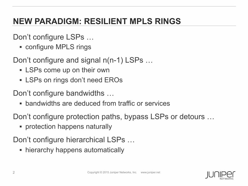
NEW PARADIGM: RESILIENT MPLS RINGS
Don’t configure LSPs … § configure MPLS rings
Don’t configure and signal n(n-1) LSPs … § LSPs come up on their own § LSPs on rings don’t need EROs
Don’t configure bandwidths … § bandwidths are deduced from traffic or services
Don’t configure protection paths, bypass LSPs or detours … § protection happens naturally
Don’t configure hierarchical LSPs … § hierarchy happens automatically
3 Copyright © 2015 Juniper Networks, Inc. www.juniper.net
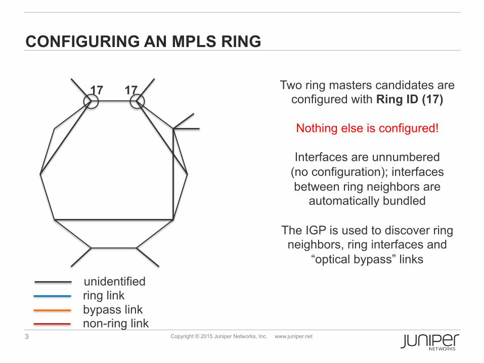
CONFIGURING AN MPLS RING
17 17 Two ring masters candidates are configured with Ring ID (17)
Nothing else is configured!
Interfaces are unnumbered
(no configuration); interfaces between ring neighbors are
automatically bundled
The IGP is used to discover ring neighbors, ring interfaces and
“optical bypass” links
ring link bypass link non-ring link
unidentified
4 Copyright © 2015 Juniper Networks, Inc. www.juniper.net
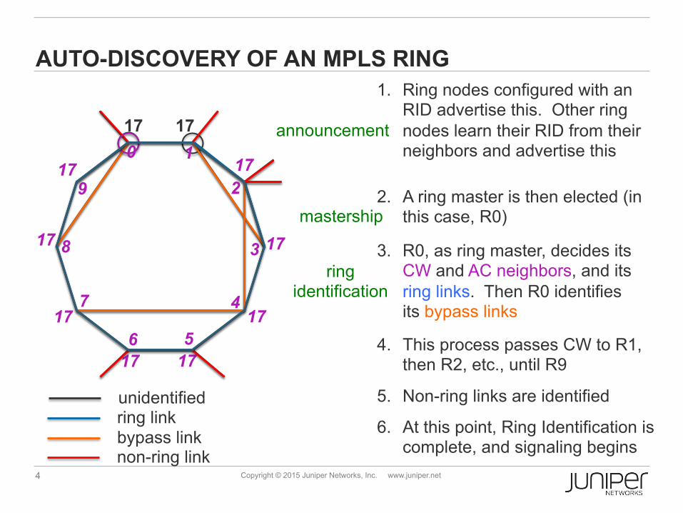
AUTO-DISCOVERY OF AN MPLS RING
17 17
17
17
17
17
17
17
17
17
1. Ring nodes configured with an RID advertise this. Other ring nodes learn their RID from their neighbors and advertise this 0 1
9 2
3
4 7
6 5
8
6. At this point, Ring Identification is complete, and signaling begins
5. Non-ring links are identified
4. This process passes CW to R1, then R2, etc., until R9
3. R0, as ring master, decides its CW and AC neighbors, and its ring links. Then R0 identifies its bypass links
2. A ring master is then elected (in this case, R0)
ring link bypass link non-ring link
unidentified
announcement
mastership
ring identification
5 Copyright © 2015 Juniper Networks, Inc. www.juniper.net
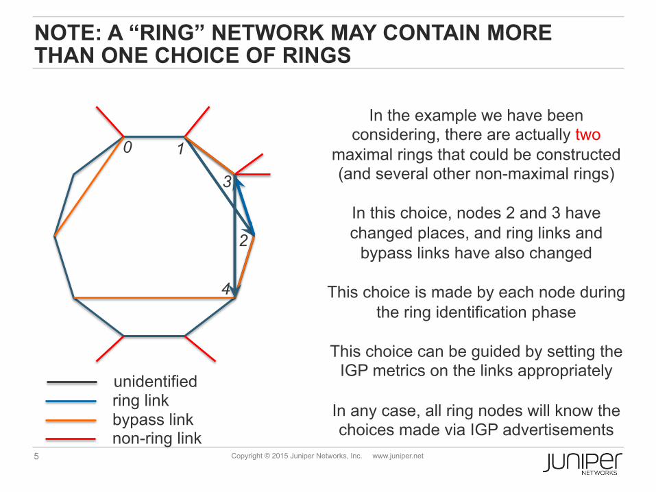
NOTE: A “RING” NETWORK MAY CONTAIN MORE THAN ONE CHOICE OF RINGS
In the example we have been considering, there are actually two
maximal rings that could be constructed (and several other non-maximal rings)
In this choice, nodes 2 and 3 have changed places, and ring links and
bypass links have also changed
This choice is made by each node during the ring identification phase
This choice can be guided by setting the
IGP metrics on the links appropriately
In any case, all ring nodes will know the choices made via IGP advertisements
ring link bypass link non-ring link
unidentified
0 1
2
3
4
6 Copyright © 2015 Juniper Networks, Inc. www.juniper.net
RING LSPs: Basics
17 0
17 1
17 2
17 5
17 9
17 3
17 4
17 6
17 7
17 8
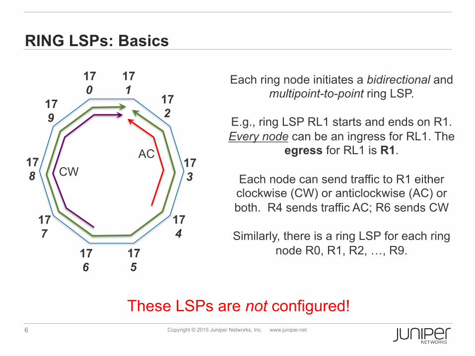
Each ring node initiates a bidirectional and multipoint-to-point ring LSP.
E.g., ring LSP RL1 starts and ends on R1. Every node can be an ingress for RL1. The
egress for RL1 is R1.
Each node can send traffic to R1 either clockwise (CW) or anticlockwise (AC) or both. R4 sends traffic AC; R6 sends CW
Similarly, there is a ring LSP for each ring
node R0, R1, R2, …, R9.
These LSPs are not configured!
CW AC
7 Copyright © 2015 Juniper Networks, Inc. www.juniper.net
RING LSPs: Signaling
17 10
17 1
17 2
17 5
17 9
17 3
17 4
17 6
17 7
17 8
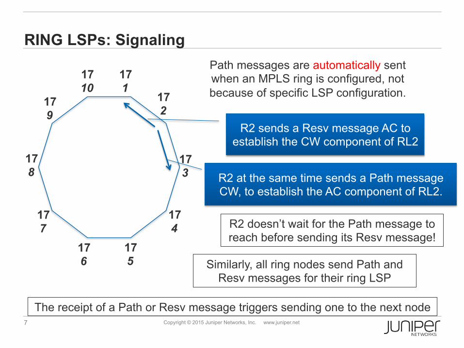
R2 sends a Resv message AC to establish the CW component of RL2
Path messages are automatically sent when an MPLS ring is configured, not because of specific LSP configuration.
R2 at the same time sends a Path message CW, to establish the AC component of RL2.
R2 doesn’t wait for the Path message to reach before sending its Resv message!
Similarly, all ring nodes send Path and Resv messages for their ring LSP
The receipt of a Path or Resv message triggers sending one to the next node
8 Copyright © 2015 Juniper Networks, Inc. www.juniper.net
RING LSPs: PROTECTION
17 10
17 1
17 2
17 5
17 9
17 3
17 4
17 6
17 7
17 8
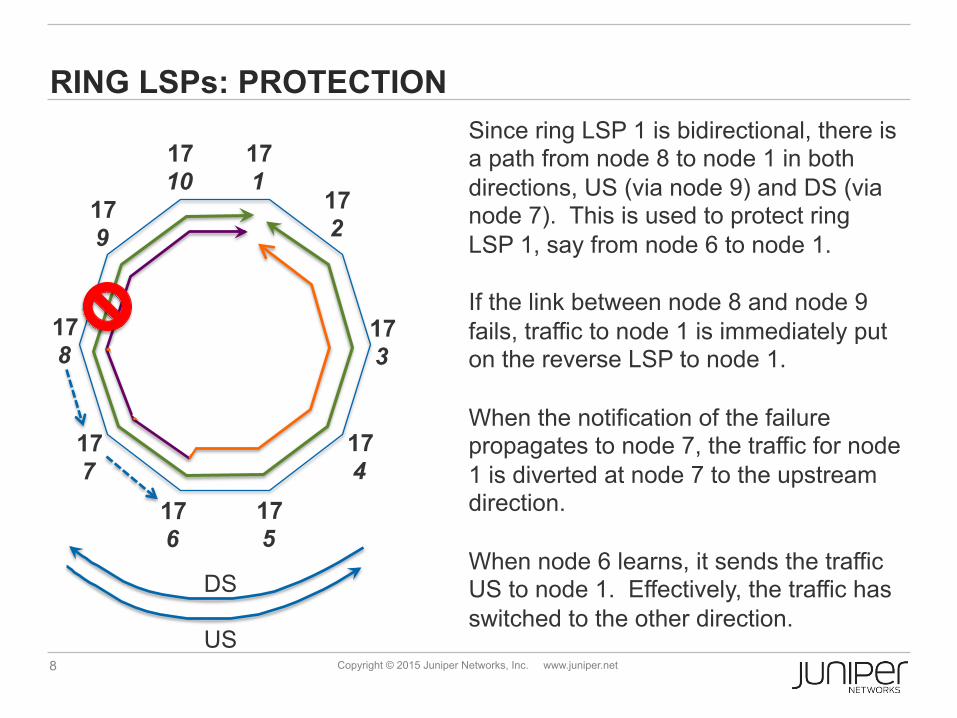
Since ring LSP 1 is bidirectional, there is a path from node 8 to node 1 in both directions, US (via node 9) and DS (via node 7). This is used to protect ring LSP 1, say from node 6 to node 1. If the link between node 8 and node 9 fails, traffic to node 1 is immediately put on the reverse LSP to node 1. When the notification of the failure propagates to node 7, the traffic for node 1 is diverted at node 7 to the upstream direction. When node 6 learns, it sends the traffic US to node 1. Effectively, the traffic has switched to the other direction.
DS
US
9 Copyright © 2015 Juniper Networks, Inc. www.juniper.net
PROTECTION (2)
For RL1, failure of the link between R8 and R9 is equivalent to the failure of node R8 or node R9
However, the failure of node R1 for RL1 is very different 1. The egress node is down. Recovery has to be via an alternative
node that with the same connectivity or service 2. Recovery as described in the previous slide will lead to a packet
loop. Some solutions for this have been suggested in the draft
Details of egress node protection will be given later
10 Copyright © 2015 Juniper Networks, Inc. www.juniper.net
OAM
To ensure fast detection of failures, OAM is run automatically on each ring link and bypass link
Each node advertises the OAM protocols it supports § On each ring link and bypass link, the OAM protocol used is one
that both nodes agree to, with a default hello time of 3.3ms § Each ring node sends an OAM message over its own ring LSP in
both the CW and AC directions, with a default hello time of 1 sec
11 Copyright © 2015 Juniper Networks, Inc. www.juniper.net
STATUS
Added an author – Luis Contreras/Telefonica
Lots of discussion on mailing list
Mail from Loa on whether MPLS WG should work on rings § Response: yes, MPLS should work on rings § Response: no, draft-cheng and RMR should not be merged
Request: make draft-kompella-mpls-rmr a WG document


![[MPLS Configuration Guide] - D-Link Academyacademy.dlink.com/temp/exam_Issue/230/MPLS Configuration Guide… · MPLS Configuration Guide Multiprotocol Label Switching (MPLS) MPLS](https://img.dokumen.tips/doc/110x75/5a815ac47f8b9ada388cfeea/mpls-configuration-guide-d-link-configuration-guidempls-configuration-guide.jpg)