Embed Size (px)
Citation preview

Residential insulated sheathing – installatiOn guide
Residential Insulated Sheathing – Installation GuideROXUL® COmfORtbOaRd™ IS

Contentsintroduction – how to use this guide .........................................................................................1
split-insulation Wall assembly ..................................................................................................2Insulation .......................................................................................................................................3
nominal and effective R-Values for split insulation Wall Configurations ..............................4Cladding Attachment and Support ..................................................................................................5
Critical Barriers and Control layers ...........................................................................................9Example of Critical Barriers within a Typical Wall Assembly......................................................... 10Water-Shedding Surface and Rainscreen ..................................................................................... 11Water-Resistive Barrier ............................................................................................................... 11Vapour Retarder ........................................................................................................................... 12Air Barrier .................................................................................................................................... 12Thermal Insulation ....................................................................................................................... 12
detailing and Other Considerations .......................................................................................... 13
single Family installation details ............................................................................................ 14 sequential details ...................................................................................................................... 15

1
Introduction – How to Use this Guidethis Single family Residential builder’s Guide covers the use of ROXUL COmfORtbOaRd™ IS within a split-insulation or exterior insulation wall assembly.
the use of split-insulation (also referred to as continuous insulation) wall assemblies is becoming more common in the residential building industry due to more stringent building and energy code requirements for the thermal performance (effective R-value) of exterior walls. the advantages of the split-insulation wall assembly over other types make it an excellent choice for the residential market.
Recent developments in enclosure design have shown the advantages of the inclusion of a ventilated wall cavity (rainscreen) into the wall assembly and an exterior membrane air barrier approach. In some jurisdictions, a rainscreen wall cavity is required within the building code for exterior walls.
Special considerations must be taken in detailing this type of wall assembly to maintain:• air barrier continuity,• water resistant barrier (moisture barrier) continuity,• thermal continuity and minimizing thermal bridges,• cladding attachment and detailing, and• adequate drainage and ventilation of the wall cavity.
the ROXul COMFORtBOaRd™ is – Residential insulated sheathing – installatiOn guide is designed to provide residential home builders and contractors with clear, detailed steps for the construction of a split-insulation wall assembly. the special considerations mentioned above are clearly addressed in each detail to ensure consistency and performance of the design.
additionally, a short building science primer explaining the functions of the various components of the wall assembly is provided.
It is important to note the information provided in this guide provides one method of detailing a split-insulation, exterior air barrier wall assembly; however, subtle changes at interface locations could be made to achieve the same intent. Review the building code requirements for your jurisdiction to ensure that all wall assembly detailing is in general conformity. The details provided here are in general conformity with Part 9 of the National Building Code of Canada, though they may exceed the minimum requirements as set out by the code.

2
split-insulation Wall assembly
the split-insulation wall assembly consists of rigid or semi-rigid insulation installed on the exterior of an above-grade, conventional 2x4 or 2x6 insulated wood-frame wall. In some areas, this wall may also be referred to as an exterior insulated wall assembly, or a wall with insulated sheathing. Rigid ROXUL COmfORtbOaRd™ IS insulation is installed on the exterior side of the sheathing membrane, attached with vertical strapping or other attachment strategy, which provides a cladding attachment surface and drained/ventilated cavity behind the cladding. a significant advantage of the split-insulation wall assembly is high effective R-values due to the continuous insulation outside of the structural framing, thereby minimizing thermal bridging. for this reason the continuous exterior insulation provides more effective R-value for the thickness installed than conventional stud cavity insulation. In addition, the interior wood elements of the assembly are kept warmer as a result of the exterior layer of insulation, thereby reducing the risk for condensation in these moisture-sensitive layers.
EXtERIOR tO INtERIOR
• Cladding• drained/vented cavity• Wood strapping, screwed through insulation• ROXUL COmfORtbOaRd™ IS rigid insulation
(thickness to meet R-value requirement)• Vapour-permeable sheathing membrane
(air-barrier)• Sheathing (plywood or OSb)• 2x4 or 2x6 wood framing with ROXUL
COmfORtbatt® insulation• Polyethylene sheet vapour barrier
(cold climates only)• Gypsum board and interior finish

3
insulation
there are many potential insulation combinations for a split-insulation wall assembly; however, the most common scenario is batt insulation installed within the stud cavity and rigid insulation installed on the exterior of the sheathing, or as the sheathing.
ROXUL COmfORtbatt® makes an ideal choice for stud cavity insulation due to its ease of installation and compatibility with split insulation wall assemblies.
ROXUL COmfORtbOaRd™ IS is an ideal choice for the exterior rigid insulation due to its ease of use, dimensional stability, noncombustibility, retained R-value over a variety of temperatures, and high vapour permeability.
Hygrothermal simulations and field experience have shown that the use of vapour permeable mineral wool insulation provides improved durability for the wood frame wall in all climate zones. alternate exterior insulation types such as vapour-impermeable foam insulation (XPS, EPS or Polyiso) can increase the risk of trapping moisture within the sheathing in the event of exterior moisture penetration or built-in construction moisture. the use of vapour-permeable ROXUL COmfORtbOaRd™ IS alleviates this concern.
the amount of exterior insulation required in the assembly will depend predominantly on three factors: the stud framing configuration (depth and spacing), the cladding attachment system, and the target R-value. for the purposes of this guide the above grade wall assembly is constructed of the following elements and provides an effective R-value of R-23.7, though is easily scalable using the same details to R-30 to R-40 or higher depending on the project needs.
• 2X6 wood studs installed at 16" O.C. (on-centre),• ROXUL COmfORtbatt® insulation (R-22) installed within the stud cavity, and• 1.5" ROXUL COmfORtbOaRd™ IS insulation (R-6) installed on the exterior of the sheathing
the following table shows the effective insulation values of different split-insulation wall assembly configurations utilizing ROXUL products.

4
Nominal and Effective R-Values for Split Insulation Wall Configurations
ROXul® COMFORtBatt® ROXul® COMFORtBatt®
16" On Centre 24" On Centre
3.5" (2X4) 5.5" (2X6) 3.5" (2X4) 5.5" (2X6)
R-14 R-22 R-14 R-22
ROXul® COMFORtBOaRd™ is 1.25" R-5
R-23.0RSI-4.04
R-31.0RSI-5.45
R-23.0RSI-4.04
R-31.0RSI-5.45
NominalR-Value
R-18.2RSI-3.2
R-23.4RSI-4.13
R-18.6RSI-3.28
R-24.1RSI-4.25
effectiveR-Value
ROXul® COMFORtBOaRd™ is 1.5" R-6
R-24.0RSI-4.22
R-32.0RSI-5.63
R-24.0RSI-4.22
R-32.0RSI-5.63
NominalR-Value
R-19.2RSI-3.38
R-24.4RSI-4.31
R-19.6RSI-3.46
R-25.1RSI-4.43
effectiveR-Value
ROXul® COMFORtBOaRd™ is 2.0" R-8
R-26.0RSI-4.57
R-34.0RSI-5.98
R-26.0RSI-4.57
R-34.0RSI-5.98
NominalR-Value
R-21.2RSI-3.73
R-26.4RSI-4.66
R-21.6RSI-3.81
R-27.1RSI-4.78
effectiveR-Value
ROXul® COMFORtBOaRd™ is 3.0" R-12
R-30.0RSI-5.27
R-38.0RSI-6.68
R-30.0RSI-5.27
R-38.0RSI-6.68
NominalR-Value
R-25.2RSI-4.43
R-30.4RSI-5.36
R-25.6RSI-4.51
R-31.1RSI-5.48
effectiveR-Value
the above table takes into account the associated elements of the wall assembly. Wall assemblies will differ in their construction and it is imperative to understand the elements of the wall and how they contribute to its thermal resistance. for the values above, a basic wall assembly was selected, including:
• exterior air film
• ¾" ventilated cavity
• ¾" lightweight wood cladding
• ½" plywood sheathing
• ½" gypsum
• interior air film
the contributing R-value of the assembly (other than insulation) is R-4.0 (RSI-0.699). Values for differentassemblies can be calculated using the thermal conductance values contained in the NbC part 9.36 tables. It is important to note that the effect of fasteners is not required for calculating NbC wall assembly R-values.

5
all types of cladding can be used with ROXUL COmfORtbOaRd™ IS in the split-insulation wall assembly. the strategy to attach the cladding will depend on the weight and support requirements for the cladding. most residential claddings can be attached directly to the vertical strapping, which is in turn attached through the insulation to the primary structure. Vertical strapping will typically consist of 1x3 or 1x4 lumber or ripped strips of ¾"plywood. 3/8" plywood would be the minimum thickness per requirements for rainscreen walls; however, it may not provide a sufficient nail base or structural rigidity for some claddings. Some builders may also wish to use 2x3 or 2x4 lumber for increased stiffness of the
cladding attachment base. When selecting the strapping material and thickness, attention should be paid to local building code requirements for ventilated cavity/capillary break openness and gap depth in your jurisdiction.
a ventilated wall cavity outboard of the rigid insulation is recommended in all climate zones. the ventilated cavity allows air flow behind the cladding on the exterior side of the insulation preventing inward vapour drive and meeting the requirements of a rainscreen assembly. Ventilated wall cavities are strongly recommended where vapour-open exterior insulations are used in conjunction with absorptive claddings like brick and in warmer climates where the predominant vapour flow is inwards. the benefits of ventilation also include reduced cladding temperatures in warm climates, which helps reduce heat gain.
the following diagrams depict the layers of a typical wall assembly for three assembly types:• Light-weight Cladding (Lap Siding)• Heavy-weight Cladding (Stucco)• Self-supported Cladding (brick Veneer)
Cladding attachment and Support

6
light-weight Cladding (lap siding) Wall assembly
Exterior to Interior:1. Light-weight cladding (WSS)2. Wood strapping (16" or 24" on centre)3. ROXUL COmfORtbOaRd™ IS rigid insulation4. Sheathing membrane (ab/WRb)5. Sheathing (OSb or Plywood)6. 2x6 stud framing with ROXUL COmfORtbatt® insulation7. Polyethylene sheet (where required)8. Gypsum wall board
12
3 4
67
5
8

7
heavy-weight Cladding (stucco or Cultured stone Veneer) Wall assembly
Exterior to Interior:1. Heavy-weight Cladding (WSS)2. Wood strapping (16" or 24" on centre)3. ROXUL CaVItYROCK® md/dd rigid insulation4. thermally broken fastener support5. Sheathing membrane (ab/WRb)6. Sheathing (OSb or Plywood)7. 2x6 stud framing with ROXUL COmfORtbatt® insulation8. Polyethylene sheet (where required)9. Gypsum wall board
1 2
3
4
5
7
6
8
9

8
self-supported Cladding (Brick Veneer) Wall assembly
Exterior to Interior:1. brick veneer (WSS)2. ROXUL CaVItYROCK® md/dd rigid insulation with stick pin fastener3. brick tie4. Sheathing membrane (ab/WRb)5. Sheathing (OSb or plywood)6. 2x6 stud framing with ROXUL COmfORtbatt® insulation7. Polyethylene sheet (where required)8. Gypsum wall board
12
3
4
76
8
5
9
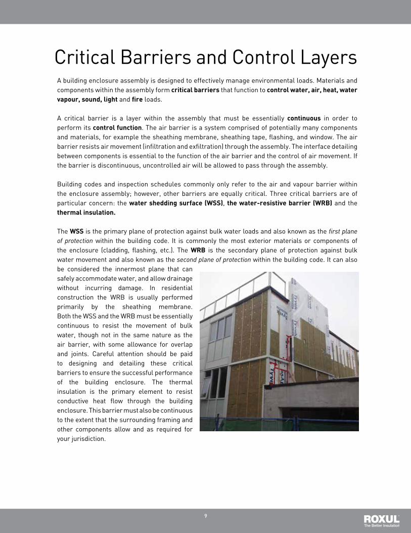
Critical barriers and Control Layersa building enclosure assembly is designed to effectively manage environmental loads. materials and components within the assembly form critical barriers that function to control water, air, heat, water vapour, sound, light and fire loads.
a critical barrier is a layer within the assembly that must be essentially continuous in order to perform its control function. the air barrier is a system comprised of potentially many components and materials, for example the sheathing membrane, sheathing tape, flashing, and window. the air barrier resists air movement (infiltration and exfiltration) through the assembly. the interface detailing between components is essential to the function of the air barrier and the control of air movement. If the barrier is discontinuous, uncontrolled air will be allowed to pass through the assembly.
building codes and inspection schedules commonly only refer to the air and vapour barrier within the enclosure assembly; however, other barriers are equally critical. three critical barriers are of particular concern: the water shedding surface (Wss), the water-resistive barrier (WRB) and the thermal insulation.
the Wss is the primary plane of protection against bulk water loads and also known as the first plane of protection within the building code. It is commonly the most exterior materials or components of the enclosure (cladding, flashing, etc.). the WRB is the secondary plane of protection against bulk water movement and also known as the second plane of protection within the building code. It can also be considered the innermost plane that can safely accommodate water, and allow drainage without incurring damage. In residential construction the WRb is usually performed primarily by the sheathing membrane. both the WSS and the WRb must be essentially continuous to resist the movement of bulk water, though not in the same nature as the air barrier, with some allowance for overlap and joints. Careful attention should be paid to designing and detailing these critical barriers to ensure the successful performance of the building enclosure. the thermal insulation is the primary element to resist conductive heat flow through the building enclosure. this barrier must also be continuous to the extent that the surrounding framing and other components allow and as required for your jurisdiction.

10
example of Critical Barriers within a typical Wall assembly
light-weight Cladding (lap siding)Wall assembly
Exterior to Interior:• Light-weight cladding• 1x3 treated wood strapping• ROXUL COmfORtbOaRd™ IS rigid insulation• thermally broken fastener support• Sheathing membrane• Sheathing (OSb or Plywood)• 2x6 stud framing with COmfORtbatt® insulation• Polyethylene sheet• Gypsum wall board
Water Shedding Surface
thermal barrier
Water Resistive barrier and air barrier
Vapour Retarder

11
Generally, the water shedding surface (WSS) is the outer surface of the wall assembly and is designed to manage bulk water in the system. a rainscreen approach assumes that some incidental moisture will likely penetrate behind the WSS and must be allowed to drain through the rainscreen cavity and out of the assembly at cross-cavity flashing locations. Water removal in the ventilated wall cavity also occurs through evaporation and is facilitated by ventilation.In the case of the split-insulation wall
assembly in this guide, the WSS is the outermost layer of the wall assembly, such as lap siding, stucco or brick veneer. the exterior rigid insulation is intended to be a secondary drainage plain, not as the primary water resistive barrier. In a rainscreen system, ROXUL COmfORtbOaRd™ IS must be installed such that an open cavity for air movement and drainage behind the cladding is provided. the ventilated wall cavity is most commonly achieved by using vertically oriented strapping onto which the cladding is fastened. the ventilated wall cavity also aids in drying out water absorptive cladding by allowing a drying surface on the backside of the cladding and reduces the inward vapour drive from solar radiation.
the water-resistive barrier (WRb) is the innermost plane that can safely accommodate water, and allow drainage without incurring damage.
In the case of the split-insulation wall assembly, the vapour-permeable sheathing membrane behind the exterior insulation functions as the WRb. the sheathing membrane must be vapour permeable to allow for some outward migration of vapour, thereby minimizing the risk of condensation within the wall assembly. there are a variety of loose and self-adhered sheet products that can be used, as well as some liquid-applied products. ROXUL COmfORtbOaRd™ IS placed outboard of the sheathing membrane will also create a supplemental drainage surface to reduce water penetration further into the assembly.
the WRb can also serve as the air barrier membrane in an exterior membrane air barrier approach. the sheathing membrane must be detailed to stop liquid moisture from the outside, as well as air infiltration and exfiltration, while still allowing outward vapour diffusion drying from the inside. the sheathing membrane is taped/sealed and sandwiched between the sheathing and the exterior insulation in this assembly.
Water-shedding surface and Rainscreen
Water-Resistive Barrier

12
In most split-insulation wall assemblies, the interior polyethylene sheet provides the primary vapour control layer. Increasingly, however, poly has been phased out in some states in favour of other methods. Review the requirements for a vapour barrier in your jurisdiction. In most of Canada, which consists of heating climates (Zones 4-7), the vapour retarder should be placed inboard of the insulation layers to limit the outward vapour drive into the wall assembly. adding insulation to the exterior of the sheathing keeps the moisture-sensitive sheathing and framing warmer and reduces the risk of condensation from interior moisture and shifts the dew point outside of the stud cavity. In cooling climates, the vapour retarding sheet typically goes outboard of the insulation.
Vapour Retarder
air Barrier
thermal insulation
the split insulation wall assembly can accommodate several air-barrier strategies. the simplest and most robust approach is to use the vapour-permeable sheathing membrane (taped and sealed) as the primary air-barrier material, though other materials may also be used. the sheathing membrane is sandwiched between the sheathing and the exterior insulation and is therefore adequately supported and relatively safe from puncture from incidental damage. Continuity of the air barrier is important and is covered by the details contained in this guide.
the thermal insulation, while not usually considered a critical barrier, performs an important control function and is useful to identify. It consists of the thermal insulation and other low-conductivity elements of the wall assembly. Proper identification of the materials used in the thermal barrier helps to minimize thermal gapping and thermal bridging. In a split-insulation wall assembly the primary thermal barrier will be the ROXUL
COmfORtbOaRd™ IS rigid insulation on the exterior and the ROXUL COmfORtbatt® insulation in the stud cavities. Other important elements to consider are thermally broken cladding supports, window frames and doors and windows.
13
detailing and Other ConsiderationsSplit-insulation wall assemblies using ROXUL COmfORtbOaRd™ IS require some simplemodifications to standard wood-frame construction practices at key interfaces and penetrations.
• the water shedding details are important in order to limit the amount of water that reaches beyond the exterior cladding.
• Cross-cavity flashings, complete with end dams and adequate sloping, will provide the most effective water shedding component at joints and interfaces in the exterior cladding.
• Where more robust support is needed at the plane of insulation, use continuous framing,
provided that it does not significantly affect the thermal performance of the wall assembly or significantly disturb drainage and ventilation of the ventilated wall cavity.
• If a heavier cladding is being used that cannot be supported by the strapping, shear blocks should be used at intermittent spacing, and its effect on the thermal performance of the wall should be included in overall thermal calculations.
• Insect control should be used at all cladding and insulation terminations to stop pests from entering behind the cladding into the ventilated wall cavity, and into the mineral wool insulation.
the split-insulation wall assembly details in this guide are designed to provide the building industry with simple, easy-to-follow instructions for detailing an external air barrier, split-insulation wall assembly that effectively controls vapour, moisture and air flow. ROXUL COmfORtbatt® and ROXUL COmfORtbOaRd™ IS insulation are ideal choices for the effective and efficient construction of such a wall assembly.
alternativesthis guide is intended to provide industry best practice guidelines for the design and construction of split-insulation wall assemblies for the residential market in all climate zones. However, it is noted that there are equally robust alternatives to the details presented here. alternative details are considered robust as long as the design and fabrication intent to maintain air and moisture barrier continuity in an effective and durable way is upheld.
many building codes in Canada require rainscreen designs for wall assemblies. In areas that do not require a rainscreen, strapping may be omitted for wall assemblies with 1.5" of exterior rigid insulation or less. Wall assemblies with exterior insulation greater than 1.5" in thickness should include strapping to ensure effective support of the cladding. Pressure treated strapping is only required in high rain areas, though it is recommended in all jurisdictions. Review the building code or your jurisdiction for more information.

14
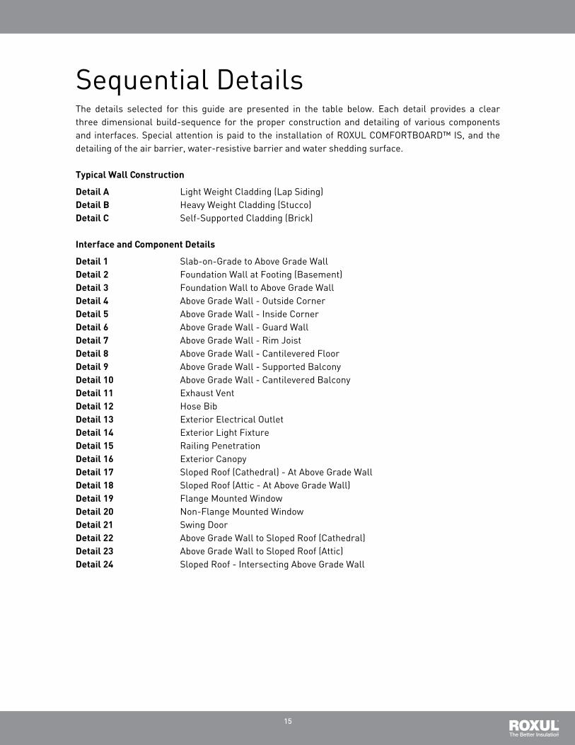
Single family Residential Installation detailsthe following section presents the list of important details typically found in a Single family dwelling (Sfd). the details provide three dimensional build-sequence drawings for the construction and detailing of the enclosure assembly at various locations on the building. Special attention is paid to correct detailing of the exterior air barrier, water-resistive barrier and water shedding surface.
the detail locations are shown graphically on the figure below. the details are numbered and correlated with the numbering system presented on the Sfd figure below, thus allowing the figure to function as cross-reference. a list of details is also provided for ease of location within the guide.
15
the details selected for this guide are presented in the table below. Each detail provides a clear three dimensional build-sequence for the proper construction and detailing of various components and interfaces. Special attention is paid to the installation of ROXUL COmfORtbOaRd™ IS, and the detailing of the air barrier, water-resistive barrier and water shedding surface.
typical Wall Construction
detail a Light Weight Cladding (Lap Siding)detail B Heavy Weight Cladding (Stucco)detail C Self-Supported Cladding (brick)
interface and Component details
detail 1 Slab-on-Grade to above Grade Walldetail 2 foundation Wall at footing (basement)detail 3 foundation Wall to above Grade Walldetail 4 above Grade Wall - Outside Cornerdetail 5 above Grade Wall - Inside Cornerdetail 6 above Grade Wall - Guard Walldetail 7 above Grade Wall - Rim Joistdetail 8 above Grade Wall - Cantilevered floordetail 9 above Grade Wall - Supported balconydetail 10 above Grade Wall - Cantilevered balconydetail 11 Exhaust Ventdetail 12 Hose bibdetail 13 Exterior Electrical Outletdetail 14 Exterior Light fixturedetail 15 Railing Penetrationdetail 16 Exterior Canopydetail 17 Sloped Roof (Cathedral) - at above Grade Walldetail 18 Sloped Roof (attic - at above Grade Wall)detail 19 flange mounted Windowdetail 20 Non-flange mounted Windowdetail 21 Swing doordetail 22 above Grade Wall to Sloped Roof (Cathedral)detail 23 above Grade Wall to Sloped Roof (attic)detail 24 Sloped Roof - Intersecting above Grade Wall
Sequential details

16
watch now at roxul.com
LIGHT WEIGHT CLADDING (LAP SIDING) – ROXUL® COMFORTBOARD™ IS EXTERIOR MEMBRANE AIR BARRIER
3.��Install�sheathing�membrane.
1.��Typical�2x6�wood�frame�construction�with�ROXUL®�COMFORTBATT®�installed�in�the�stud�cavities.��
2.��Install�sheathing.������������
1
2 3
Light�Weight�Cladding�(Lap�Siding)
1

17
LIGHT WEIGHT CLADDING (LAP SIDING) – ROXUL® COMFORTBOARD™ IS EXTERIOR MEMBRANE AIR BARRIER
4.��Install�ROXUL®�COMFORTBOARDTM�IS�and�secure�with�strapping.
5.��Install�cladding�(lap�siding).
4 5

18
HEAVY WEIGHT CLADDING (STUCCO) – ROXUL® COMFORTBOARD™ IS EXTERIOR MEMBRANE AIR BARRIER
3.��Install�sheathing�membrane.
1.��Typical�2x6�wood�frame�construction�with�ROXUL®�COMFORTBATT®�installed�in�the�stud�cavities.��
2.��Install�sheathing.������������
1
2 3
Heavy�Weight�Cladding�(Stucco)
1
watch now at roxul.com

19
4.��Install�thermally�broken�strapping�supports.� 5.��Install�CAVITYROCK®�MD/DD�and�secure�with�strapping.����
6.��Install�backer�board.� 7.�Install�wire�support�mesh.��
8.��Install�stucco�finish.�����������
8
4 5
6 7

20
watch now at roxul.com
SELF-SUPPORTED CLADDING (BRICK) – ROXUL® COMFORTBOARD™ IS EXTERIOR MEMBRANE AIR BARRIER
3.��Install�sheathing�membrane.
1.��Typical�2x6�wood�frame�construction�with�ROXUL®�COMFORTBATT®�installed�in�the�stud�cavities.��
2.��Install�sheathing.������������
1
2
3
Self-Supported�Cladding�(Brick)
1

21
SELF-SUPPORTED CLADDING (BRICK) – ROXUL® COMFORTBOARD™ IS EXTERIOR MEMBRANE AIR BARRIER
4.��Install�ROXUL®�COMFORTBOARD™�IS�and�secure�with�strapping.�Provide�brick�ties�as�required�to�provide�lateral�resistance.�
5.��Install�brick.����
45

1
SLAB-ON-GRADE TO ABOVE GRADE WALL – ROXUL® COMFORTBOARD™ IS EXTERIOR MEMBRANE AIR BARRIER
1. Typical wood frame construction at sheathing installation.
4. Install sheathing membrane and seal leading edge with sheathing tape to complete air barrier continuity. Provide a ¾" vision line on the flashing backleg.
2. Install waterproofing membrane. Ensure a minimum of 2" overlap of waterproofing membrane onto sheathing.
3. Install prefinished metal flashing and seal leading edge to the underlying waterproofing membrane with sheathing tape to provide for air barrier continuity.
1
2
3 4
Slab-on-grade to Above Grade Wall
watch now at roxul.com

2
SLAB-ON-GRADE TO ABOVE GRADE WALL – ROXUL® COMFORTBOARD™ IS EXTERIOR MEMBRANE AIR BARRIER
7. Install perforated pipe and filter fabric at the base of the footing. Surround with drain rock.
9. Install ROXUL® COMFORTBOARD™ IS. Use strapping to hold the insulation in place. Fasten the strapping to the wall. Provide bugscreens at the top and bottom of the strapping.
5. Install ROXUL® rigid board insulation over foundation waterproofing and up tight to the underside of the flashing. Spot adhere the insulation to the foundation wall to avoid puncture of the waterproofing membrane.
10. Install cladding.
6. Install concrete protection board over below-grade insulation.
8. Backfill against the foundation wall. Ensure finished grade height is a minimum of 8" below the top of the foundation wall and slopes away from the building.
7
65
8
9
10

3
watch now at roxul.com
Foundation Wall at Footing (Basement)
FOUNDATION WALL AT FOOTING (BASEMENT) – ROXUL® COMFORTBOARD™ IS EXTERIOR MEMBRANE AIR BARRIER
1. Intersection of the concrete foundation wall with the footing.
4. Install ROXUL® rigid board insulation against foundation wall. Spot adhere the insulation to prevent puncture of the waterproofing membrane.
2. Install the below-grade waterproofing membrane. Ensure the membrane wraps over the footing and terminates on the vertical.
3. Install perforated pipe with filter fabric at the base of the footing and fill around with drain rock.
1 2
34
FOUNDATION WALL AT FOOTING (BASE-MENT) – ROXUL® COMFORTBOARD™ IS EXTERIOR MEMBRANE AIR BARRIER

4
FOUNDATION WALL AT FOOTING (BASEMENT) – ROXUL® COMFORTBOARD™ IS EXTERIOR MEMBRANE AIR BARRIER
7. Install ROXUL® rigid board insulation in a strip the height of the slab along the base of the foundation wall. The insulation absorbs differential movement between the slab and foundation and provides a thermal break.
5. Install ROXUL® rigid board insulation at grade. Ensure the insulation is installed tight to the foundation wall.
6. Install poly over the insulation and seal the leading edge to the foundation wall with acoustical sealant to maintain air barrier continuity. Seal laps in the poly with acoustical sealant and sheathing tape on the leading edge.
8. Place reinforcing and pour slab-on-grade concrete.
7
6
5
8
5
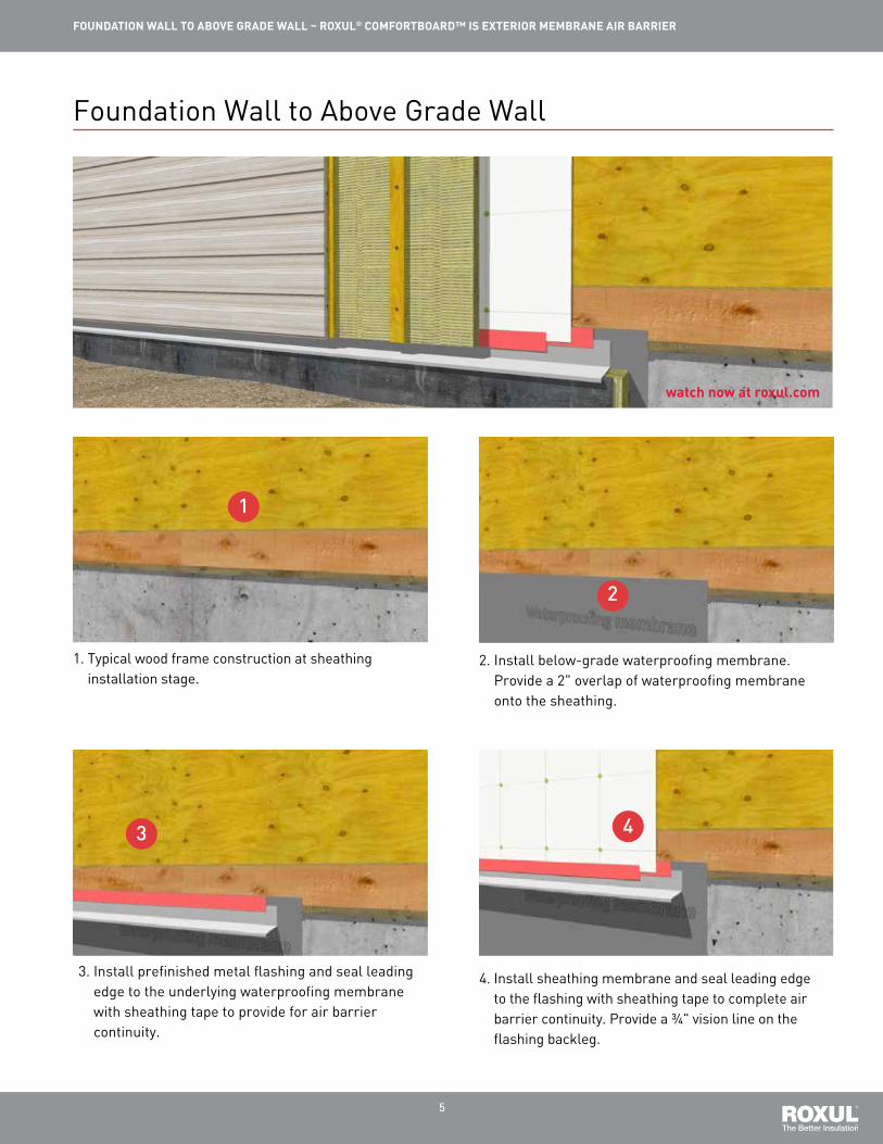
FOUNDATION WALL TO ABOVE GRADE WALL – ROXUL® COMFORTBOARD™ IS EXTERIOR MEMBRANE AIR BARRIER
1. Typical wood frame construction at sheathing installation stage.
4. Install sheathing membrane and seal leading edge to the flashing with sheathing tape to complete air barrier continuity. Provide a ¾" vision line on the flashing backleg.
2. Install below-grade waterproofing membrane. Provide a 2" overlap of waterproofing membrane onto the sheathing.
3. Install prefinished metal flashing and seal leading edge to the underlying waterproofing membrane with sheathing tape to provide for air barrier continuity.
1
2
3 4
FOUNDATION WALL AT FOOTING (BASE-MENT) – ROXUL® COMFORTBOARD™ IS EXTERIOR MEMBRANE AIR BARRIER
Foundation Wall to Above Grade Wall
watch now at roxul.com

6
FOUNDATION WALL TO ABOVE GRADE WALL – ROXUL® COMFORTBOARD™ IS EXTERIOR MEMBRANE AIR BARRIER
7. Install ROXUL® COMFORTBOARD™ IS. Use strapping to hold the insulation; secure in place with recommended fasteners. Provide bugscreens at the top and bottom of the strapping.
5. Install ROXUL® rigid board insulation over foundation waterproofing and up tight to the underside of flashing. Spot adhere the insulation to the foundation wall to avoid puncture of the waterproofing membrane.
6. Install concrete protection board over insulation. Back fill dirt around the foundation wall.
8. Install cladding.
7
65
8

7
ABOVE GRADE WALL AT OUTSIDE CORNER – ROXUL® COMFORTBOARD™ IS EXTERIOR MEMBRANE AIR BARRIER
1. Typical wood frame construction at sheathing installation stage.
4. The corner trim boards must be nailed together as well as to the strapping to form the corner.
2. Install ROXUL® COMFORTBOARD™ IS. Use the strapping to support the insulation and secure in place with recommended fasteners. Provide bugscreens at the top and bottom of the strapping.
3. Install strapping as required to support the corner trim boards and cladding. Install corner trim boards.
1
2
34
FOUNDATION WALL AT FOOTING (BASE-MENT) – ROXUL® COMFORTBOARD™ IS EXTERIOR MEMBRANE AIR BARRIER
Above Grade Wall at Outside Corner
watch now at roxul.com

8
ABOVE GRADE WALL AT OUTSIDE CORNER – ROXUL® COMFORTBOARD™ IS EXTERIOR MEMBRANE AIR BARRIER
5. Install cladding.
5

9
ABOVE GRADE WALL AT INSIDE CORNER – ROXUL® COMFORTBOARD™ IS EXTERIOR MEMBRANE AIR BARRIER
1. After installation of the sheathing membrane, install a strip of sheathing tape on either side of the corner to provide reinforcement.
4. Install corner trim boards.
2. Install ROXUL® COMFORTBOARD™ IS. Use strapping to secure the insulation in place with recommended fasteners. Provide bugscreens at the top and bottom of the strapping.
3. Prepare corner trim boards by nailing them together before installation.
1
2
34
FOUNDATION WALL AT FOOTING (BASE-MENT) – ROXUL® COMFORTBOARD™ IS EXTERIOR MEMBRANE AIR BARRIER
Above Grade Wall at Inside Corner
watch now at roxul.com

10
5. Install cladding.
5
ABOVE GRADE WALL AT INSIDE CORNER – ROXUL® COMFORTBOARD™ IS EXTERIOR MEMBRANE AIR BARRIER

11
watch now at roxul.com
ABOVE GRADE WALL AT GUARD WALL – ROXUL® COMFORTBOARD™ IS EXTERIOR MEMBRANE AIR BARRIER
1. Install the first stud for the guard wall. Bed the stud in sealant and apply sealant to each short side to seal the plywood on the guard wall.
4. Install sheathing membrane to the above grade wall. Seal the leading edges to the deck membrane with sheathing tape to maintain air barrier continuity.
2. Frame the vented guard wall and slide into place over the first stud.
3. Install waterproof deck membrane. Return the deck membrane up the adjacent walls a minimum of 8".
12
34
reverse side
Above Grade Wall at Guard Wall

12
ABOVE GRADE WALL AT GUARD WALL – ROXUL® COMFORTBOARD™ IS EXTERIOR MEMBRANE AIR BARRIER
7. Seal the leading edge of the sheathing membrane with sheathing tape. Do not seal the bottom edge as the membrane is designed as a part of the moisture barrier, not the air barrier.
9. Install gussets constructed from self-adhered membrane at the corners of the guard wall to the above grade wall interface.
5. Install non-bitumious self-adhered membrane in the corner. Ensure the flashing adheres to the plywood on the guard wall and the adjacent sheathing membrane to provide for air barrier continuity.
10. Install a shoulder flashing constructed from self-adhered membrane to provide for air barrier continuity. Extend the flashing 2" onto the guard wall and 2" down the face of the above grade wall.
6. Install sheathing membrane on the guard wall. Notch out the corner of the sheathing membrane to expose a 2" portion of the self-adhered corner flashing. This is necessary to maintain air barrier continuity in subsequent steps.
8. Install self-adhered membrane over the guard wall and extend to the adjacent above grade wall. Provide a minimum 4" return up the wall and a minimum of 2" return on the sides.
7
6
5
8
910

13
ABOVE GRADE WALL AT GUARD WALL – ROXUL® COMFORTBOARD™ IS EXTERIOR MEMBRANE AIR BARRIER
13. Install ROXUL® COMFORTBOARD™ IS and secure in place with strapping. Provide bugscreens at the top and bottom of the strapping.
15. Install cladding. Leave a gap around the flashing to allow for sealant.
11. Install sheathing membrane on the above grade wall. Notch out around the guard wall. Ensure the membrane laps over all other membranes.
16. Install backer rod and sealant at the gap between the flashing and the cladding.
12. Seal the leading edge of the sheathing membrane with sheathing tape to maintain air barrier continuity.
14. Install prefinished metal flashing to the top of the guard wall. Fasten the flashing to the strapping.
1112
13 14
1516

14
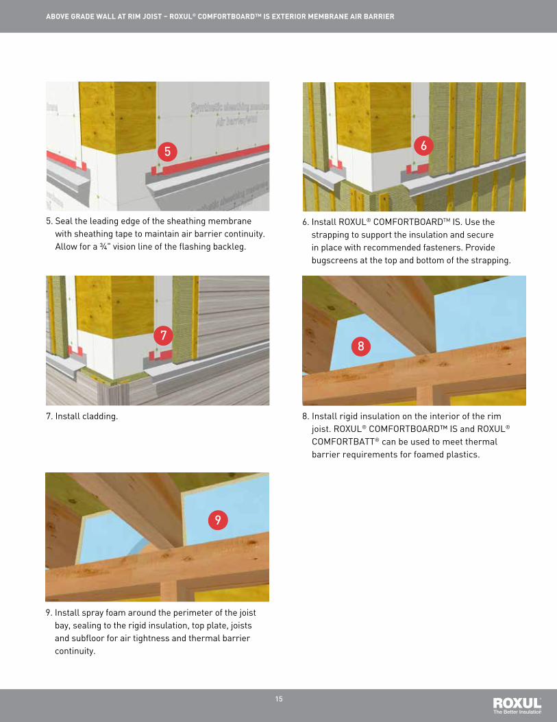
ABOVE GRADE WALL AT RIM JOIST – ROXUL® COMFORTBOARD™ IS EXTERIOR MEMBRANE AIR BARRIER
1. Typical wood frame construction at sheathing installation stage.
4. Install upper layer of sheathing membrane. Lap the membrane over the flashing.
2. Install sheathing membrane and flashing.
3. Seal the leading edge of the flashing with sheathing tape to provide for air barrier continuity.
12
3 4
Above Grade Wall at Rim Joist
watch now at roxul.com
15
ABOVE GRADE WALL AT RIM JOIST – ROXUL® COMFORTBOARD™ IS EXTERIOR MEMBRANE AIR BARRIER
7. Install cladding.
9. Install spray foam around the perimeter of the joist bay, sealing to the rigid insulation, top plate, joists and subfloor for air tightness and thermal barrier continuity.
5. Seal the leading edge of the sheathing membrane with sheathing tape to maintain air barrier continuity. Allow for a ¾" vision line of the flashing backleg.
6. Install ROXUL® COMFORTBOARDTM IS. Use the strapping to support the insulation and secure in place with recommended fasteners. Provide bugscreens at the top and bottom of the strapping.
8. Install rigid insulation on the interior of the rim joist. ROXUL® COMFORTBOARD™ IS and ROXUL® COMFORTBATT® can be used to meet thermal barrier requirements for foamed plastics.
7
65
8
9

16
watch now at roxul.com
ABOVE GRADE WALL AT CANTILEVERED FLOOR – ROXUL® COMFORTBOARD™ IS EXTERIOR MEMBRANE AIR BARRIER
1. Typical wood frame construction at sheathing stage.
4. Install sheathing membrane along the cantilevered floor joists. Seal all leading edges with sheathing tape to maintain air barrier continuity. Fold corners on the upturn and seal the fold with sheathing tape.
2. Install ROXUL® COMFORTBATT® in the cantilevered floor joist cavities. Ensure insulation extends through to the interior plane of the wall assembly to maintain thermal continuity.
3. Install sheathing membrane. Cut to allow the membrane beside the cantilevered floor to extend up the wall 8".
1
2
34
Above Grade Wall at Cantilevered Floor

17
ABOVE GRADE WALL AT CANTILEVERED FLOOR – ROXUL® COMFORTBOARD™ IS EXTERIOR MEMBRANE AIR BARRIER
7. Seal the leading edge of the flashing backleg with sheathing tape to provide for air barrier continuity.
9. Seal the leading edge of the sheathing membrane with sheathing tape to maintain air barrier continuity.
10. Install ROXUL® COMFORTBOARD™ IS and strapping. Provide bugscreens at the top and bottom of the strapping. Optional: Install ROXUL® COMFORTBOARD™ IS and strapping to the underside of the cantilevered floor.
5. Install gussets constructed of sheathing tape to cover the pinholes at the inside corners.
6. Install prefinished metal flashing around the base of the cantilevered section.
8. Lap sheathing membrane over the flashing.
7
65
8
9
10

18
ABOVE GRADE WALL AT CANTILEVERED FLOOR – ROXUL® COMFORTBOARD™ IS EXTERIOR MEMBRANE AIR BARRIER
11. Install cladding and vented soffit material.
11
19
watch now at roxul.com
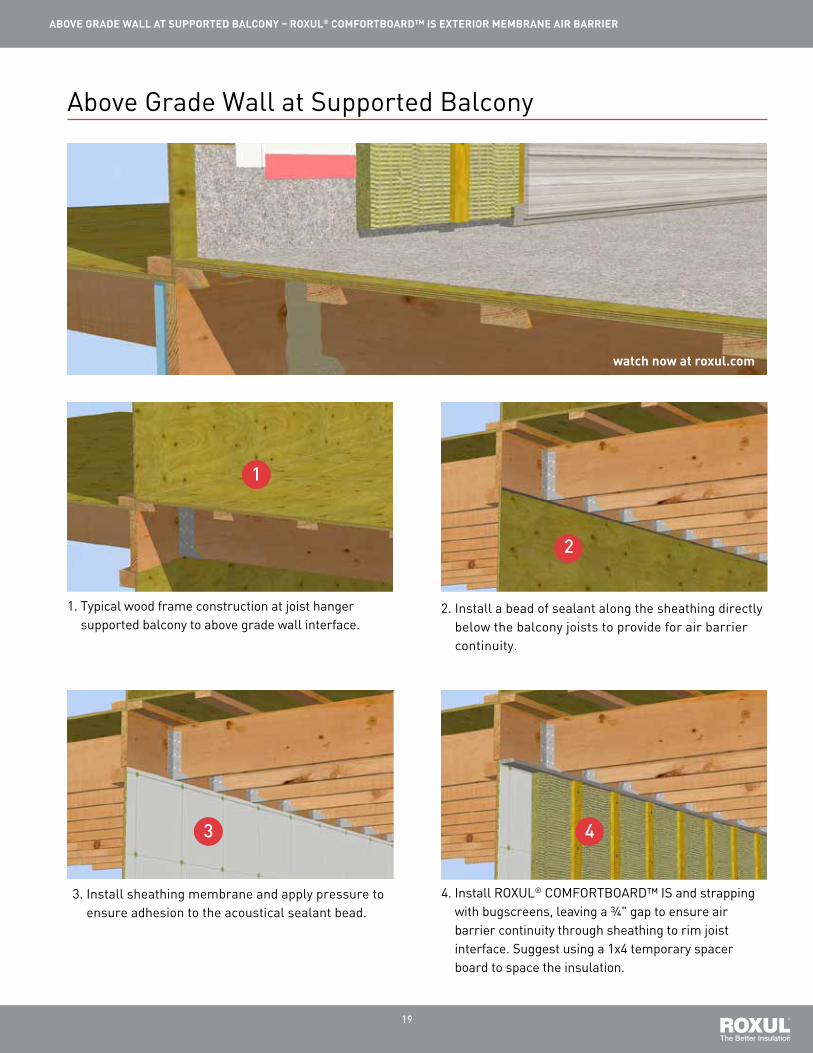
ABOVE GRADE WALL AT SUPPORTED BALCONY – ROXUL® COMFORTBOARD™ IS EXTERIOR MEMBRANE AIR BARRIER
1. Typical wood frame construction at joist hanger supported balcony to above grade wall interface.
4. Install ROXUL® COMFORTBOARD™ IS and strapping with bugscreens, leaving a ¾" gap to ensure air barrier continuity through sheathing to rim joist interface. Suggest using a 1x4 temporary spacer board to space the insulation.
2. Install a bead of sealant along the sheathing directly below the balcony joists to provide for air barrier continuity.
3. Install sheathing membrane and apply pressure to ensure adhesion to the acoustical sealant bead.
1
2
3 4
Above Grade Wall at Supported Balcony

20
ABOVE GRADE WALL AT SUPPORTED BALCONY – ROXUL® COMFORTBOARD™ IS EXTERIOR MEMBRANE AIR BARRIER
7. Install sheathing membrane and seal the leading edge to the balcony membrane with sheathing tape to maintain air barrier continuity.
9. Install cladding. 10. Install ROXUL® COMFORTBATT® in the interior stud cavities.
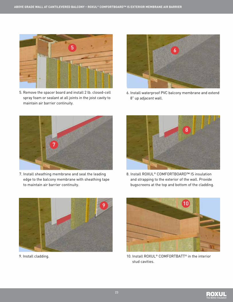
5. Remove the spacer board and install 2 lb. closed-cell spray foam or sealant at all joints in the joist cavity to maintain air barrier continuity.
6. Install waterproof PVC balcony membrane and extend 8" up adjacent wall.
8. Install ROXUL® COMFORTBOARD™ IS insulation and strapping to the exterior of the wall. Provide bugscreens at the top and bottom of the cladding.
7
65
8
910

21
ABOVE GRADE WALL AT SUPPORTED BALCONY – ROXUL® COMFORTBOARD™ IS EXTERIOR MEMBRANE AIR BARRIER
11. Install 3" rigid insulation in joist cavities. ROXUL® COMFORTBOARD™ IS and ROXUL® COMFORTBATT® can be used to meet thermal barrier protection requirements for foamed plastics.
12. Install 2 lb. closed-cell spray or sealant around the perimeter of the rigid insulation to ensure air tightness and thermal barrier continuity.
1112
13. Install cladding and vented soffit panels below balcony.
13

22
watch now at roxul.com
ABOVE GRADE WALL AT CANTILEVERED BALCONY – ROXUL® COMFORTBOARD™ IS EXTERIOR MEMBRANE AIR BARRIER
1. Typical wood frame construction at cantilevered balcony to above grade wall interface.
4. Install ROXUL® COMFORTBOARD™ IS and strapping with bugscreens, leaving a ¾" gap between the insulation and the top of the wall. Suggest using a 1x4 temporary spacer board to space the insulation.
2. Install a bead of sealant along the sheathing directly below the balcony joists to provide for air barrier continuity.
3. Install sheathing membrane and apply pressure to ensure adhesion to the sealant bead.
1
2
3 4
Above Grade Wall at Cantilevered Balcony
23
ABOVE GRADE WALL AT CANTILEVERED BALCONY – ROXUL® COMFORTBOARD™ IS EXTERIOR MEMBRANE AIR BARRIER
7. Install sheathing membrane and seal the leading edge to the balcony membrane with sheathing tape to maintain air barrier continuity.
9. Install cladding. 10. Install ROXUL® COMFORTBATT® in the interior stud cavities.
5. Remove the spacer board and install 2 lb. closed-cell spray foam or sealant at all joints in the joist cavity to maintain air barrier continuity.
6. Install waterproof PVC balcony membrane and extend 8" up adjacent wall.
8. Install ROXUL® COMFORTBOARD™ IS insulation and strapping to the exterior of the wall. Provide bugscreens at the top and bottom of the cladding.
7
65
8
9 10

24
ABOVE GRADE WALL AT CANTILEVERED BALCONY – ROXUL® COMFORTBOARD™ IS EXTERIOR MEMBRANE AIR BARRIER
11. Install rigid insulation in joist cavities. ROXUL® COMFORTBOARD™ IS and ROXUL® COMFORTBATT® can be used to meet thermal barrier protection requirements for foamed plastics.
12. Install 2 lb. closed-cell spray or sealant around the perimeter of the rigid insulation to ensure air tightness and thermal barrier continuity.
11 12
13. Install cladding and vented soffit panels to the underside of the balcony.
13

25
watch now at roxul.com
EXHAUST VENT – ROXUL® COMFORTBOARD™ IS EXTERIOR MEMBRANE AIR BARRIER
1. Install exhaust vent duct into an appropriately sized penetration in the sheathing and sheathing membrane. Place blocking/support on the interior side of the wall if required to secure the duct in place.
4. Seal the leading edge of the foil-faced membrane with mastic or another compatible sealant.
2. Install horseshoe-shaped self-adhered membrane below the exhaust vent.
3. Install horseshoe-shaped self-adhered membrane above the exhaust vent. Taper the top of the membrane to facilitate water drainage.
12
3
4
FOUNDATION WALL AT FOOTING (BASE-MENT) – ROXUL® COMFORTBOARD™ IS EXTERIOR MEMBRANE AIR BARRIER
Exhaust Vent

26
EXHAUST VENT – ROXUL® COMFORTBOARD™ IS EXTERIOR MEMBRANE AIR BARRIER
7. Install adaptor flange and secure to the support strapping.
10. Install prefinished metal flashing below the exhaust vent hood.
5. Apply sealant between the exhaust vent and the self-adhered membrane to maintain air barrier continuity.
6. Install ROXUL® COMFORTBOARD™ IS and strapping. Provide bugscreens at the top and bottom of the strapping. Provide strapping around penetration to support the adaptor flange.
8. Apply backer rod and sealant between the duct and the adaptor flange to avoid air leakage into the wall cavity.
9. Install exhaust vent hood, bedded in sealant to the adaptor flange.
910
7
65
8

27
EXHAUST VENT – ROXUL® COMFORTBOARD™ IS EXTERIOR MEMBRANE AIR BARRIER
11. Install cladding and trim boards around the exhaust vent hood.
14. Install cladding.
12. Apply a bead of sealant between the exhaust vent hood and the trim boards (top and sides).
13. Install prefinished metal flashing above the vent hood trim.
12
13
14
FOUNDATION WALL AT FOOTING (BASE-MENT) – ROXUL® COMFORTBOARD™ IS EXTERIOR MEMBRANE AIR BARRIER
11

28
watch now at roxul.com
HOSE BIB – ROXUL® COMFORTBOARD™ IS EXTERIOR MEMBRANE AIR BARRIER
1. Install sheathing membrane at the proposed penetration for the hose bib.
4. Install the bottom sheet of foil-faced, self-adhered membrane, ensuring a tight fit to the underside of the hose bib.
2. Install frost-free hose bib through an appropriately sized penetration.
3. Construct a two-part backing of foil-faced, self-adhered membrane as shown above.
12
3 4
FOUNDATION WALL AT FOOTING (BASE-MENT) – ROXUL® COMFORTBOARD™ IS EXTERIOR MEMBRANE AIR BARRIER
Hose Bib

29
HOSE BIB – ROXUL® COMFORTBOARD™ IS EXTERIOR MEMBRANE AIR BARRIER
7. Apply a bead of sealant around the perimeter of the hose bib, ensuring good adhesion to the foil-faced membrane to maintain air barrier continuity.
10. Install sheathing membrane and seal the leading edge with sheathing tape to maintain air barrier continuity. Ensure the membrane positively laps over other membranes and flashing.
5. Install top sheet of foil-faced membrane. Positively lap the top sheet over the bottom sheet a minimum of 2".
6. Apply mastic or other compatible sealant at the leading edge of the foil-faced membrane.
8. Install blocking to support the hose bib and onto which the face plate will be attached.
9. Install prefinished metal flashing above the hose bib and seal the leading edge with sheathing tape to provide for air barrier continuity.
910
7
65
8

30
HOSE BIB – ROXUL® COMFORTBOARD™ IS EXTERIOR MEMBRANE AIR BARRIER
11. Install ROXUL® COMFORTBOARDTM IS and strapping. Provide bugscreens at the top and bottom of the strapping.
14. Install the bottom block and sill flashing. The sill flashing is fastened to the back of the bottom block.
12. Create the wood face plate from dimensional lumber. The diameter of the hole in the center is equal to the diameter of pipe on the hose bib.
13. Install the top piece of the wood face plate and secure in place.
12
1314
FOUNDATION WALL AT FOOTING (BASE-MENT) – ROXUL® COMFORTBOARD™ IS EXTERIOR MEMBRANE AIR BARRIER
11
16. Apply sealant around the perimeter of the face plate and sill flashing (bottom and sides).
15. Install the cladding.
15 16

31
watch now at roxul.com
EXTERIOR ELECTRICAL OUTLET – ROXUL® COMFORTBOARD™ IS EXTERIOR MEMBRANE AIR BARRIER
1. Install sheathing membrane starter strip under proposed electrical outlet installation site.
4. Seal around the perimeter of the electrical wire housing to the foil-faced, self-adhered membrane to maintain air barrier continuity.
2. Install foil-faced, self-adhered membrane at the location of the electrical outlet.
3. Pull the electrical wire through the wall and foil-faced, self-adhered membrane.
12
34
FOUNDATION WALL AT FOOTING (BASE-MENT) – ROXUL® COMFORTBOARD™ IS EXTERIOR MEMBRANE AIR BARRIER
Exterior Electrical Outlet

32
EXTERIOR ELECTRICAL OUTLET – ROXUL® COMFORTBOARD™ IS EXTERIOR MEMBRANE AIR BARRIER
7. Install ROXUL® COMFORTBOARD™ IS and strapping. Provide bugscreens at the top and bottom of the strapping.
10. Install sealant around the perimeter of the electrical box (top and sides).
5. Install prefinished metal flashing over the penetration and seal with sheathing tape to provide for air barrier continuity.
6. Install second layer of sheathing membrane and lap over the metal flashing. Seal the leading edge with sheathing tape to maintain air barrier continuity.
8. Install electrical box.
9. Install cladding.
9 10
7
65
8

33
watch now at roxul.com
EXTERIOR LIGHT FIXTURE – ROXUL® COMFORTBOARD™ IS EXTERIOR MEMBRANE AIR BARRIER
1. Install sheathing membrane at proposed electrical outlet installation site.
4. Seal around the perimeter of the electrical cable to maintain air barrier continuity.
2. Install a piece of foil-faced, self-adhered membrane over the sheathing membrane. Taper top edge to facilitate drainage and install sealant.
3. Pull wire through both membranes.
12
3 4
FOUNDATION WALL AT FOOTING (BASE-MENT) – ROXUL® COMFORTBOARD™ IS EXTERIOR MEMBRANE AIR BARRIER
Exterior Light Fixture

34
EXTERIOR LIGHT FIXTURE – ROXUL® COMFORTBOARD™ IS EXTERIOR MEMBRANE AIR BARRIER
7. Install watertight, exterior light fixture box.
5. Install sheathing membrane and seal the leading edge with sheathing tape to maintain air barrier continuity. Ensure a positive lap over the preceding membranes.
6. Install ROXUL® COMFORTBOARD™ IS and secure in place with strapping. Provide strapping at the site of the exterior light penetration and pull the electrical wire through it. Provide bugscreens at the top and bottom of the strapping.
8. Install cladding and provide backer rod and sealant around the perimeter of the exterior light fixture box.
9. Install light fixture per manufacturer’s specifications.
9
7
65
8

35
watch now at roxul.com
RAILING PENETRATION – ROXUL® COMFORTBOARD™ IS EXTERIOR MEMBRANE AIR BARRIER
1. Install two blocks between interior studs where railing penetration will occur. This will provide structural support for the engineered railing attachment.
4. Install treated wood blocking on the self-adhered membrane. Install self-adhered membrane over top of the blocking to aid in water diversion.
2. Install starter sheathing membrane under area where railing will meet the wall.
3. Install a backing of self-adhered membrane over the starter sheathing membrane. Install sealant at the top and sides of the self-adhered membrane.
12
3 4
FOUNDATION WALL AT FOOTING (BASE-MENT) – ROXUL® COMFORTBOARD™ IS EXTERIOR MEMBRANE AIR BARRIER
Railing Penetration

36
RAILING PENETRATION – ROXUL® COMFORTBOARD™ IS EXTERIOR MEMBRANE AIR BARRIER
7. Install the cladding.
5. Install sheathing membrane and seal the leading edge to maintain air barrier continuity. Ensure the sheathing membrane laps over all previous membranes.
6. Install ROXUL® COMFORTBOARD™ IS and strapping. Provide bugscreens at the top and bottom of the strapping.
8. Install the railing. Fasteners must be sized to reach the blocking placed in the stud wall.
9. Install backer rod and sealant between the railing support flange and the cladding.
9
7
65
8

37
watch now at roxul.com
EXTERIOR CANOPY – ROXUL® COMFORTBOARD™ IS EXTERIOR MEMBRANE AIR BARRIER
1. Install starter sheathing membrane under area where canopy will meet the wall.
4. Install waterproof canopy deck membrane. Return the membrane 8" up the adjacent wall.
2. Install canopy framing.
3. Install canopy roof deck material.
1 2
3 4
Exterior Canopy

38
7. Install sheathing membrane. Lap the membrane over the closure flashing and seal the leading edge with sheathing tape to maintain air barrier continuity.
5. Install shingles. 6. Install prefinished metal closure flashing and seal the leading edge with sheathing tape to provide for air barrier continuity.
8. Install ROXUL® COMFORTBOARD™ IS and secure in place with strapping. Provide bugscreens at the top and bottom of the strapping.
9. Install cladding and closure flashing. 10. Install ROXUL® COMFORTBOARD™ IS on the exterior of the wall between canopy ledger boards with recommended fasteners.
9 10
7
65
8
EXTERIOR CANOPY – ROXUL® COMFORTBOARD™ IS EXTERIOR MEMBRANE AIR BARRIER

39
13. Install cladding.
11. Install sheathing membrane below the canopy. Ensure the membrane laps under the starter strip. Seal the leading edge of the starter strip membrane with sheathing tape to maintain air barrier continuity.
14. Install vented soffit material.
12. Install ROXUL® COMFORTBOARD™ IS and secure in place with strapping. Provide bugscreens at the top and bottom of the strapping.
13
11
14
12
EXTERIOR CANOPY – ROXUL® COMFORTBOARD™ IS EXTERIOR MEMBRANE AIR BARRIER

40
watch now at roxul.com
SLOPED ROOF (CATHEDRAL) TO ABOVE GRADE WALL – ROXUL® COMFORTBOARD™ IS EXTERIOR MEMBRANE AIR BARRIER
1. Install a starter strip of sheathing membrane to extend above and below the roof plane. This will allow for air-barrier transition to be completed later.
4. Install shingles and provide venting at the top of the roof.
2. Attach a ledger board and roof framing.
3. Install waterproof membrane. Extend the roof membrane 8" up the wall.
12
3
4
Sloped Roof (Cathedral) to Above Grade Wall

41
SLOPED ROOF (CATHEDRAL) TO ABOVE GRADE WALL – ROXUL® COMFORTBOARD™ IS EXTERIOR MEMBRANE AIR BARRIER
7. Install ROXUL® COMFORTBOARD™ IS and secure with strapping. Provide bugscreens at the top and bottom of the strapping.
5. Install a metal closure flashing and seal the leading edge with sheathing tape to the waterproof membrane, to provide for air barrier continuity.
6. Install sheathing membrane and lap over the metal flashing. Seal the leading edge with sheathing tape to complete air barrier transition.
8. Install cladding.
9. Install ROXUL® COMFORTBATT® in the rafter cavities. 10. Apply a bead of sealant between the sheathing and sheathing membrane below the roof to increase air tightness.
9
10
7
65
8

42
SLOPED ROOF (CATHEDRAL) TO ABOVE GRADE WALL – ROXUL® COMFORTBOARD™ IS EXTERIOR MEMBRANE AIR BARRIER
13. Install interior finishes.
11. Apply a bead of sealant to the exterior of the sheathing membrane for air barrier continuity.
12. Install poly and seal the leading edge to the sheathing membrane with staples through the poly at the sealant bead to complete the air barrier transition.
13
11
12

43
watch now at roxul.com
SLOPED ROOF (ATTIC) TO ABOVE GRADE WALL – ROXUL® COMFORTBOARD™ IS EXTERIOR MEMBRANE AIR BARRIER
1. Install a starter strip of sheathing membrane to extend above and below the roof plane. This will allow for air-barrier transition to be completed later.
4. Install shingles and provide venting at the top of the roof.
2. Attach joist hangers and roof framing.
3. Install roof deck and waterproof membrane. Extend the waterproof membrane 8" up the wall.
1
2
3
4
Sloped Roof (Attic) to Above Grade Wall

44
SLOPED ROOF (ATTIC) TO ABOVE GRADE WALL – ROXUL® COMFORTBOARD™ IS EXTERIOR MEMBRANE AIR BARRIER
7. Install ROXUL® COMFORTBOARD™ IS and secure with strapping. Provide bugscreens at the top and bottom of the strapping.
5. Install a metal closure flashing and seal the leading edge with sheathing tape to the waterproof membrane, to provide for air barrier continuity.
6. Install sheathing membrane and lap over the metal flashing. Seal the leading edge with sheathing tape to complete the air barrier continuity.
8. Install cladding.
9. Apply a bead of sealant between the sheathing and sheathing membrane below the roof to increase air tightness.
10. Apply a bead of sealant to the exterior of the sheathing membrane to provide for air barrier continuity.
9
10
7
65
8

45
SLOPED ROOF (ATTIC) TO ABOVE GRADE WALL – ROXUL® COMFORTBOARD™ IS EXTERIOR MEMBRANE AIR BARRIER
13. Install ROXUL® COMFORTBATT® in the attic space. Insulate wall adjoining attic space and occupied space with ROXUL® COMFORTBATT®.
11. Install poly and seal the leading edge to the sheathing membrane with staples through the poly at the sealant bead to complete the air barrier continuity.
12. Install interior finishes.
13
11 12

46
watch now at roxul.com
FLANGE MOUNTED WINDOW – ROXUL® COMFORTBOARD™ IS EXTERIOR MEMBRANE AIR BARRIER
1. Typical wood frame construction at sheathing stage.
4. Install self-adhered membrane gussets at lower corners.
2. Install starter strip of sheathing membrane below the window rough opening. Seal the leading edge with sheathing tape.
3. Install self-adhered sill membrane. Extend membrane up the jambs and onto the face of the wall.
12
3 4
Flange Mounted Window
6"

47
FLANGE MOUNTED WINDOW – ROXUL® COMFORTBOARD™ IS EXTERIOR MEMBRANE AIR BARRIER
7. Install sheathing membrane pre-strips at the jambs and extend onto face of wall a minimum of 8". Seal the leading edges with sheathing tape.
6. Install self-adhered subsidiary sill membrane to aid in water diversion. Leave backer on unsupported portion of the membrane until after exterior insulation is installed.
5. Install self-adhered membrane at sill corners, extending up the jamb to the height of the sheathing membrane. Finish the self-adhered membrane 2" onto the face of the wall.
8. Install sheathing membrane at the head of the rough opening, extending a minimum of 12" up the face of the wall. Seal the leading edges with sheathing tape.
9. Install 3/8" furring strips around the jambs and head and intermittently at the sill to allow for drainage. The nailing flange will be mounted onto the furring strips.1
10. Install and structurally attach the window per manufacturer’s specifications.
9 10
7
65
8
2"
1The furring strips keep the window in place, while providing good sub-sill drainage. The furring strips are not required for window installation, but are included here as an alternative best practice to conventional window installations.
8" 12"

48
FLANGE MOUNTED WINDOW – ROXUL® COMFORTBOARD™ IS EXTERIOR MEMBRANE AIR BARRIER
13. Install metal flashing at the head of the window. Seal the leading edge of the flashing with sheathing tape.
14. Install sheathing membrane. Ensure positive laps over all other layers. Seal the leading edge with sheathing tape.
11. Install backer rod and sealant around the interior perimeter of the window to complete air barrier continuity.
12. Install sheathing tape along the jambs of the window frame and extend to the face of the wall.
1314
11
12
16. Install prefinished metal sill flashing. Attach the sill flashing to the nailing flange under the window sill.
15. Install ROXUL® COMFORTBOARD™ IS and secure with strapping. Provide bugscreens at the top and bottom of the strapping.
2"
15
16

49
FLANGE MOUNTED WINDOW – ROXUL® COMFORTBOARD™ IS EXTERIOR MEMBRANE AIR BARRIER
19. Install metal flashing to the strapping over the top window trim board.
17. Apply sealant between the metal flashing and the window sill.
18. Install window trim boards.
20. Install cladding.
21. Apply sealant around the perimeter of the window (top and sides) between the frame and the window trim boards.
1718
1920
21

50
watch now at roxul.com
NON-FLANGE MOUNTED WINDOW – ROXUL® COMFORTBOARD™ IS EXTERIOR MEMBRANE AIR BARRIER
1. Typical wood frame construction at sheathing stage.
4. Install secondary self-adhered sill membrane to aid in diverting water outboard of the exterior insulation. Leave the facer on the unsupported portion of the membrane until insulation is installed.
2. Install starter strip of sheathing membrane below the window rough opening. Seal the leading edge with sheathing tape.
3. Install self-adhered sill membrane. Extend membrane up the jambs and onto the face of the wall.
12
3 4
Non-Flange Mounted Window
1.5"

51
NON-FLANGE MOUNTED WINDOW – ROXUL® COMFORTBOARD™ IS EXTERIOR MEMBRANE AIR BARRIER
7. Install sheathing membrane pre-strips at the jambs and extend onto face of wall a minimum of 8". Lap the sheathing membrane over the self-adhered membrane at the corners and seal the leading edges with sheathing tape.
5. Install self-adhered membrane gussets at lower corners.
6. Install self-adhered membrane at sill corners, extending up the jamb to the height of the sheathing membrane. Finish the self-adhered membrane 2" onto the face of the wall.
8. Install sheathing membrane at the head of the rough opening, extending a minimum of 12" up the face of the wall. Seal the leading edges with sheathing tape.
9. Install and structurally attach window per manufacturer’s specifications.
10. Install backer rod and sealant around the jamb and head of the window to aid in water diversion.
9 10
7
65
88" 12"
2"

52
NON-FLANGE MOUNTED WINDOW – ROXUL® COMFORTBOARD™ IS EXTERIOR MEMBRANE AIR BARRIER
13. Install self-adhesive membrane over the prefinished metal flashing and extend 2" up the face of the wall.
14. Install sheathing membrane. Ensure positive laps over all other layers. Seal the leading edge with sheathing tape.
11. Install backer rod and sealant around the interior perimeter of the window to complete air barrier continuity.
12. Install head flashing using wood blocks to space it beyond the insulation layer.
13 14
11
12
16. Install prefinished metal sill flashing. Refer to window manufacturer’s specifications for more information.
15. Install ROXUL® COMFORTBOARD™ IS and secure with strapping. Provide bugscreens at the top and bottom of the strapping.
2"
1516

53
NON-FLANGE MOUNTED WINDOW – ROXUL® COMFORTBOARD™ IS EXTERIOR MEMBRANE AIR BARRIER
19. Install window trim.
17. Apply sealant between the metal flashing and the window sill.
18. The window trim boards (face and returns) must be nailed together either before or during installation.
20. Install cladding.
21. Install sealant around the perimeter of the window between the trim boards and the window frame (top and sides).
1718
19 20
21
54
watch now at roxul.com
SWING DOOR – ROXUL® COMFORTBOARD™ IS EXTERIOR MEMBRANE AIR BARRIER
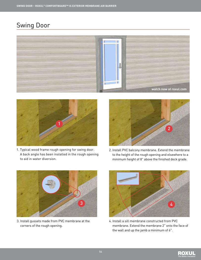
1. Typical wood frame rough opening for swing door. A back angle has been installed in the rough opening to aid in water diversion.
4. Install a sill membrane constructed from PVC membrane. Extend the membrane 2" onto the face of the wall and up the jamb a minimum of 6".
2. Install PVC balcony membrane. Extend the membrane to the height of the rough opening and elsewhere to a minimum height of 8" above the finished deck grade.
3. Install gussets made from PVC membrane at the corners of the rough opening.
12
3 4
Swing Door

55
SWING DOOR – ROXUL® COMFORTBOARD™ IS EXTERIOR MEMBRANE AIR BARRIER
7. Install sheathing membrane at the head. Return the sheathing membrane into the rough opening.
5. Install sheathing membrane at the jambs and seal the leading edge with sheathing tape. Extend the membrane into the rough opening.
6. Install gussets constructed from sheathing tape at the upper corners of the rough opening.
8. Install sheathing tape at the leading edges of the sheathing membrane to maintain air barrier continuity.
9. Install sub-sill prefinished metal flashing. Adhere to the PVC deck membrane to avoid puncture of the membrane.
10. Install and structurally attach swing door per manufacturer’s specifications.
910
7
65
8

56
SWING DOOR – ROXUL® COMFORTBOARD™ IS EXTERIOR MEMBRANE AIR BARRIER
13. Install prefinished metal flashing above the swing door head. Block the flashing out beyond the plane of insulation using treated wood blocking.
14. Install self-adhered membrane over the wood blocking. Extend the membrane onto the adjacent wall and the prefinished metal flashing.
11. Install backer rod and sealant around the exterior perimeter of the door frame.
12. Install backer rod and sealant around the interior perimeter of the door frame to maintain air barrier continuity.
13 14
11
12
16. Install sheathing membrane from above and seal the leading edge with sheathing tape to maintain air barrier continuity. Ensure the sheathing membrane laps over membrane layers below.
15. Install sheathing membrane to the rest of the wall. Seal the vertical leading edge with sheathing tape to maintain air barrier continuity.
1516
57
SWING DOOR – ROXUL® COMFORTBOARD™ IS EXTERIOR MEMBRANE AIR BARRIER
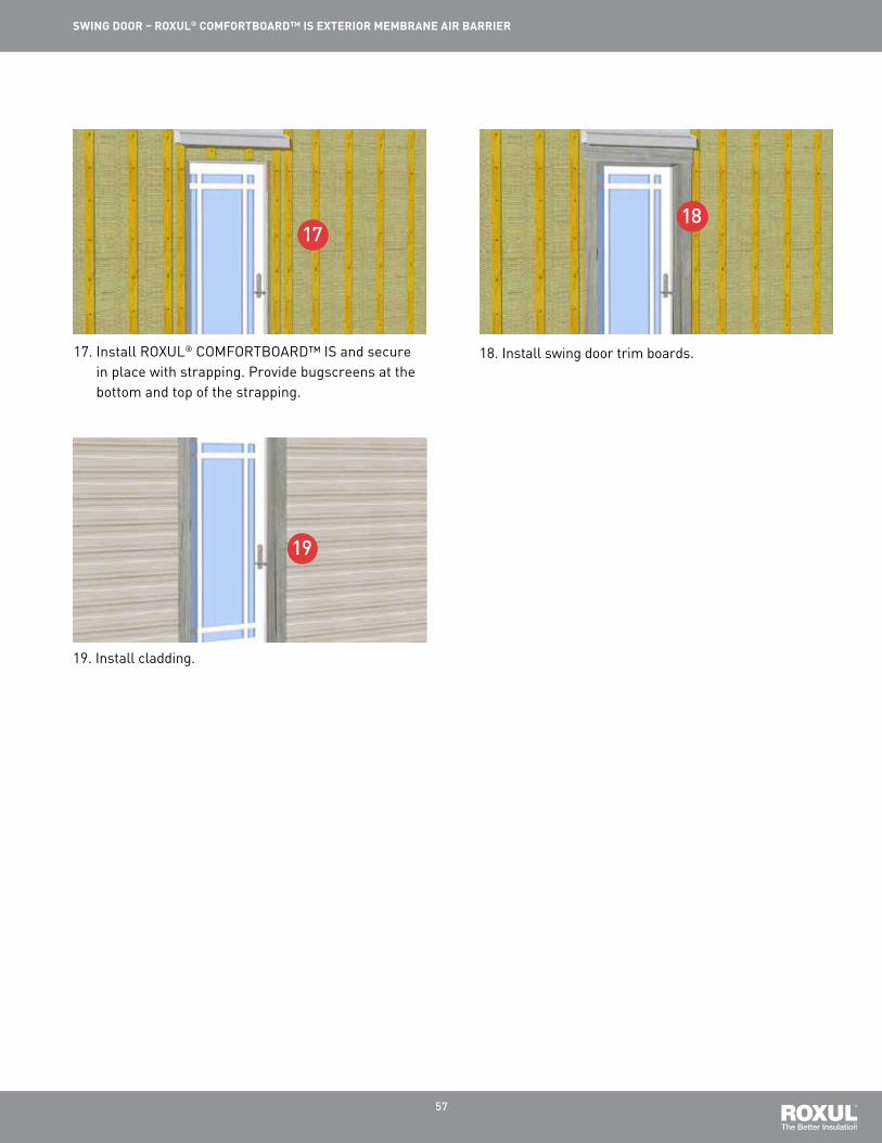
19. Install cladding.
17. Install ROXUL® COMFORTBOARD™ IS and secure in place with strapping. Provide bugscreens at the bottom and top of the strapping.
18. Install swing door trim boards.
1718
19

58
watch now at roxul.com
ABOVE GRADE WALL TO SLOPED ROOF (CATHEDRAL) – ROXUL® COMFORTBOARD™ IS EXTERIOR MEMBRANE AIR BARRIER
1. Install a starter strip of sheathing membrane between the top plates of the exterior walls. This will allow the air barrier to transition from the exterior sheathing membrane to the interior poly.
4. Seal the leading edge of the starter strip sheathing membrane with sheathing tape to maintain air barrier continuity.
2. Install roof framing and roofing.
3. Install lower sheathing membrane. Make sure to lap under the starter strip.
1
2
3
4
Above Grade Wall to Sloped Roof (Cathedral)

59
ABOVE GRADE WALL TO SLOPED ROOF (CATHEDRAL) – ROXUL® COMFORTBOARD™ IS EXTERIOR MEMBRANE AIR BARRIER
7. Install cladding. Allow for venting of the wall cavity at the top of the cladding underside of the soffit.
5. Install soffit material and vents. 6. Install ROXUL® COMFORTBOARD™ IS and strapping to the exterior of the wall. Provide bugscreens at the top and bottom of the strapping.
8. Install ROXUL® COMFORTBATT® in the stud cavities and roof cavity. Provide venting per building code requirements.
9. Install the poly sheet on the interior face of the wall. Fasten the poly to the sheathing membrane with staples at each stud.
10. Install a bead of acoustical sealant on the sheathing membrane at the lower top plate to transition the air barrier from the wall to the ceiling.
9 10
7
6
5
8

60
ABOVE GRADE WALL TO SLOPED ROOF (CATHEDRAL) – ROXUL® COMFORTBOARD™ IS EXTERIOR MEMBRANE AIR BARRIER
11. Install the poly sheet to the underside of the roof rafters. Fasten the poly sheet to the sheathing membrane with staples at the sealant bead to complete the air seal and seal the leading edge with sheathing tape.
12. Install interior finishes.
11 12

61
watch now at roxul.com
ABOVE GRADE WALL TO SLOPED ROOF (ATTIC) – ROXUL® COMFORTBOARD™ IS EXTERIOR MEMBRANE AIR BARRIER
1. Install a starter strip of sheathing membrane between the top plates of the exterior walls. This will allow the air barrier to transition from the exterior sheathing membrane to the interior poly.
4. Install sheathing tape at the leading edge of the sheathing membrane to complete air barrier continuity.
2. Install roof framing and roofing.
3. Install lower sheathing membrane. Make sure to lap under the starter strip.
1
2
34
Above Grade Wall to Sloped Roof (Attic)

62
ABOVE GRADE WALL TO SLOPED ROOF (ATTIC) – ROXUL® COMFORTBOARD™ IS EXTERIOR MEMBRANE AIR BARRIER
7. Install soffit materials and venting.
5. Install a 2x4 ledger board to support the soffit material and venting.
6. Install ROXUL® COMFORTBOARD™ IS and secure with recommended fasteners.
8. Install ROXUL® COMFORTBOARD™ IS and strapping. Provide bugscreens at the top and bottom of the strapping.
9. Install cladding. Provide venting at the top of the wall to allow for the free movement of air through the wall cavity. It is not recommended to vent the wall cavity into the roof.
10. Install ROXUL® COMFORTBATT® within the interior stud cavities.
9
10
7
6
5
8

63
ABOVE GRADE WALL TO SLOPED ROOF (ATTIC) – ROXUL® COMFORTBOARD™ IS EXTERIOR MEMBRANE AIR BARRIER
11. Install poly and fasten to the sheathing membrane at each stud with staples.
12. Install a bead of acoustical sealant to the sheathing membrane at the lower top plate to transition the air barrier from the wall to the ceiling.
11 12
13. Install poly to the underside of the roof rafters and fasten with staples at the sealant bead to complete the air seal. Seal the leading edge of the poly with sheathing tape to maintain vapour barrier continuity.
14. Install interior finishes.
15. Install ROXUL® COMFORTBATT® and/or ROXUL® ROCKFILL® in the attic space.
13
14
15

64
watch now at roxul.com
SLOPED ROOF AT INTERSECTING WALL – ROXUL® COMFORTBOARD™ IS EXTERIOR MEMBRANE AIR BARRIER
1. Install a starter strip of sheathing membrane that will extend beyond the framing of the roof.
4. Install roof framing and deck material.
2. Construct the exterior load bearing wall. The wall must be bedded in sealant to the extent of the starter strip of sheathing membrane. See next step.
3. Bed the wall in sealant to ensure air barrier continuity.
1 2
3 4
Sloped Roof at Intersecting Wall

65
SLOPED ROOF AT INTERSECTING WALL – ROXUL® COMFORTBOARD™ IS EXTERIOR MEMBRANE AIR BARRIER
11. Seal all edges of the sheathing membrane with sheathing tape.
12. Install ROXUL® COMFORTBOARD™ IS and secure in place with strapping. Provide bugscreens at the top and bottom of the strapping.
11 12
13. Install cladding and trim. 14. Install poly on the walls and fasten to the sheathing membrane with staples.
15. Install a bead of acoustical sealant along the sheathing membrane in line with the lower top plate of the exterior wall.
16. Install poly to the underside of the roof framing and fasten with staples at the sealant bead to complete the air seal. Seal the leading edge with sheathing tape.
13
14
15 16

66
SLOPED ROOF AT INTERSECTING WALL – ROXUL® COMFORTBOARD™ IS EXTERIOR MEMBRANE AIR BARRIER
17. Install interior finishes. 18. Install ROXUL® COMFORTBATT® in the attic to the depth necessary to achieve desired R-value.
17
18

ROXul inC.420 Bronte st. s. suite 105Milton, Ontario l9t 0h9Phone: 1-800-265-6878Fax: [email protected]
13a76 ROXUL COmfORtbOaRd IS Installation Guide September 15 2014Comfortboard™ is a trademark of ROXUL Inc. ®/tm: US - owner ROCKWOOL International a/S used under license; Canada - owner ROXUL Inc.
a Global Leader
ROXUL Inc. is part of ROCKWOOL International, the largest producer of stone wool insulation, which is made from natural basalt rock and recycled material. ROCKWOOL International was founded in 1909 and today operates worldwide with more than 9,800 employees, with 27 factories across three continents. ROCKWOOL has over 75 years in the insulation business and for 25 years ROXUL® has been serving the North american market, manufacturing stone wool insulation products for residential, commercial, industrial and OEm applications.
ROXUL is the better Insulation
ROXUL insulation is innovative, offering a world of green features. When ROXUL is the specified insulation, green building developers can earn a variety of LEEd® (Leadership in Energy and Environmental design) points across four key categories toward sustainable development.
Environmentally Sustainable
Our stone wool production process utilizes some of the most advanced technology available. the last decade has seen a new generation of ROXUL manufacturing facilities that are designed to lower our environmental footprint. these endeavors have included the capture and recycle rainwater, reduction in energy consumption, and zero waste to landfill by the recycling of raw materials back into the production process. ROXUL facilities also use natural lighting and re-purpose water used during the manufacturing process to minimize the impact on the environment and surrounding community resources.
ROXUL insulation is created using naturally occurring, inorganic raw materials and reuses waste from other manufacturers as well as from our plants. Stone wool insulation is noncombustible and achieves its thermal performance without the use of blowing agents. the products therefore do not off-gas over time, contributing to a sustainable environment.
Each ROXUL plant uses a varying combination of new and recycled content in order to remain efficient and environmentally friendly. ROXUL is committed to improving our overall efficiencies which further solidifies our commitment to environmental stewardship within the organization.
for further details contact your ROXUL sales representative. Please visit roxul.com for the latest information.
dISCLaImER aNd LImItatION Of LIabILItY: the statements and data contained in this brochure are for general information purposes ONLY. they are NOt specific technical recommendations as to any particular design or application and the ultimate determination as to product suitability is the sole responsibility of the installer or end user. although the information contained herein, including ROXUL product descriptions, is believed to be correct at the time of publication, accuracy cannot be guaranteed. ROXUL fully reserves the right to make product specification changes, without notice or obligation, and to modify or discontinue any of its products at any time. In no event shall ROXUL be liable for any direct, indirect, or conse-quential damages of any kind arising from information contained in this brochure, including, but not limited to, claims for loss of profits, business interruption, or damages to business reputation. this limitation of liability shall apply to all claims whether those claims are based in contract, tort, or any legal cause of action. SURfaCE bURNING CHaRaCtERIStICS: ULC Listed to Canadian Standard CaN/ULC S102 ; UL Classified to UL 723.