Embed Size (px)
Citation preview

,
4
RESEARCH AT HIGHER SUPERSONIC SPEEDS
by
SUPERSONIC FREE-FLIGHT WIND TUNNEL
• -
In the last few years, interest in supersonic aerodynamics
at speeds well beyond the speed of sound has grown tremendously.
.. This growth has been stimulated by the large-scale effort to
develop missiles for military use. The supersonic free-flight
wind tunnel which you see on your right is one outgrowth of
this interest in very high-speed aerodynamics. It is a new
piece of research equipment developed to allow experimentation
at and beyond the highest speeds considered practical at the
present time. .,
Tests have been made in this tunnel at eight times the
speed of sound, that is, a Mach number of 8. At an altitude of<"
20 miles this corresponds to a speed of 5,500 miles per hour.
The equipment is believed to be capable of testing models at a
Mach number of 15, but the major research effort is being
focused on important problems in the Mach number range from
3 to 8 rather than on achieving the maximum test speed. An
important feature of the tunnel is its ability to test at any
speed below the maximum, and tests have been made at less than
the speed of sound.
Missile designers must know the magnitude, direction, and
point of application of the forces exerted on bodies in super
"' sonic flight. The purpose of this wind tunnel is to permit
measurement of these forces. Specifically, some of the

• •
measurements needed are: The drag force, which is the air
resistance to forward motion of a body; the lift force, which
is the aerodynamic force available for supporting the body'
against gravity and for executing turns; and the point of
application of the lift force, which determines the stability
of a missile in flight. These forces, and several others, are
being studied in this wind tunnel, and some of the results of
the tests will be shown by the next speaker.
The distinctive feature of this wind tunnel is the manner
in which the high Mach number is obtained, and can be explained
with the aid of this model of the wind tunnel. First, a supe~
sonic air flow at Mach number 2 is established in the test
section, with the air moving from left to right at 1600 ft./sec.
Then, the model is shot at high speed from a gun, and moves
from right to left, upstream through the air flow. The velocity
of the model through the air is the sum of the air velocity
and the model velocity. The high Mach number is due partly to t
this high velocity, and partly to the fact that the speed of
sound in the test section is reduced due to cooling of the air
in expanding through the nozzle. Because the speed of sound
in the test section is reduced from 1120 to 830 ft./sec., the
Mach number is increased by 1/3.
The test Mach number is varied by controlling the velocity
of the model, through selection of proper powder charges. Mach
numbers below 4 can be obtained by firing with no air flow in
the tunnel, the Mach number being altogether due to the speed of
the model.

------
... The test models used, in common with full-scale missiles
and projectiles, must be stable in flight. That is, they must
not tumble, but must move through the test section nose forward
and with only moderate angles of attack. Some models are
naturally stable and tend to line up with the wind. Models
with fins are in this class. Others are naturally unstable
and must be stabilized gyroscopically by spinning, as is done ..
in conventional rifles.
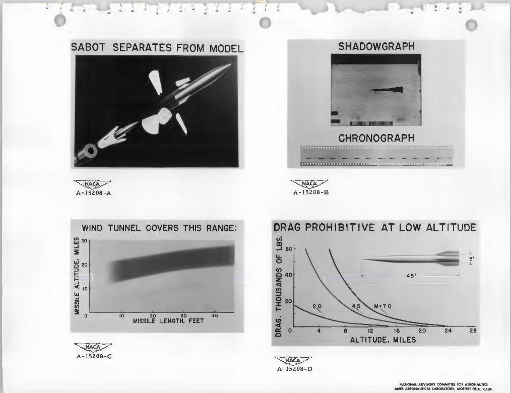
Most of the models used in this wind tunnel are fired in
plastic carriers called sabots. These sabots provide support
for the model while in the gun and make possible the use of
models with fins. Since the sabot must break away from the
model just after it leaves the gun, it is constructed in such
a manner that the aerodynamic forces acting on the fingers
cause them to break off and fall away.
There, the model and sabot are shown close to the gun, as
yet unseparated. Here, the sabot fingers may be seen in the
process of falling away.
The methods used to obtain aerodynamic data in this tunnel
will now be explained by Mr.
The fact that the model is in motion during the test
requires the use of new techniques to obtain the desired aero
dynamic data. In general, the forces are computed from the 1' ..
observed behavior of the model in flight, as is done in ballistic
ranges. For example: The drag force decelerates the model and
if the deceleration is known the drag force can be calculated.

••
·•
The deceleration can be computed if the times required to cover
successive distance intervals are known. Therefore, instruments
are used to record accurately the length of three consecutive
distance intervals and the times required by the model to cover
these intervals. The manner in which this is done is illus
trated in the model of the wind tunnel, in which some of the
important elements of the instrumentation are represented. All
of the elements shown below the wind tunnel here, are actually
located in an 8-foot pit beneath the real wind tunnel.
As the model moves through the wind-tunnel test section,
four shadowgraph pictures of it are made, at stations which are
5 feet apart. As the model approaches each station it partially
interrupts a light beam which falls on a phototube. This
interruption causes a spark to be fired when the model is in
the center of the shadowgraph station. Light from the spark is
made parallel by reflection from a spherical mirror, and then
passes through optical windows in the tunnel walls and past the
model to expose a glass photographic plate just above the tunnel.
An invar scale, which serves as the basis for distance
measurement, extends through all four stations. It is mounted
above the tunnel a few inches below the photographic plates
and is not represented on the schematic model. The image of the
scale may be seen at the top of this typical shadowgraph of a
fin stabilized model in flight. The model position, and details
of the air flow and shock wave system are permanently recorded
as shown. Distance intervals, accurate to a few thousandths of
an inch, can be measured with this system.

>
•
The standard used for measurement of time is a piezo ..
electric crystal, which controls the flashing of a mercury arc
lamp. Light pulses are produced by the lamp at precisely
" . uniform time intervals. Several hundred light pulses are
. produced while the projectile moves from station 1 to station 4.
These pulses are directed by an optical system of lenses .and
mirrors to a strip of 35 mm film placed at the circumference of
a 5-foot-diameter film drum. At the center of this drum is a
mirror, which reflects the vertical incident light over to the
film. In operation, the mirror is rotated at high speed such
that it makes one revolution as the projectile moves from
station 1 to station 4, spacing the light pulses uniformly
along the film. This is a small section of a chronograph film
and in this case the time interval between pips is 1/50,000 of
a second.
When a spark fires in a shadowgraph station, a part of the
light is allowed to escape from the side of the gap. This light
is directed along the same path used by the mercury lamp pulses,
and a spot image of the spark light is formed on the 35 mm film.
Thus, the complete time record consists of a 15-foot length of
film with several hundred uniformly spaced mercury lamp pips,
and four station pips, located at the approximate quarter points
-" of the length. The time elapsed between any two spark firings
can be determined by counting whole intervals and interpolating
the intervals where the station pip occurs. Times measured
using this apparatus are believed to be correct within

one ten millionth of a second. A physical feeling for the ..
amount of time represented by one ten millionth of a second
can be acquired when it is realized that light, traveling at
186,000 miles per second, travels only 100 feet in this time.
This ext~eme accuracy in time and distance measurement is
necessary for accurate measurement of drag in this wind tunnel.
In order that a connected picture of the fUnction of the
various parts may be obtained, the model of the wind tunnel
will now be operated.
(1) The projectile, on leaving the gun, moves through the
wind:-tunnel diffuser. During this phase, separation of the sabot
takes place.
(2) As the model enters station l photobeam, the photo
tube signal opens a quick-acting shutter called the optical
gate and the mercury arc lamp pulses begin to expose the film.
After the proper time delay, spark No. 1 fires, producing
shadowgraph No. l and a station pip on the time film.
(3) Light pulses from the mercury lamp and the spark gaps
can be seen reaching the chronograph film.
(4) The firing of the spark in station 4 automatically
turns off the mercury lamp.
(5) The model proceeds through the nozzle into the model
catcher, ending the test. The elapsed time since the model left
the gun is only a few hundredths of a second.
Testing in the real wind tunnel will now be demonstrated.
The model used will be a commercial bullet, fired in a

------
. .,. 220 Swift rifle at a muzzle velocity of 4100 ft/sec. In order ....
to avoid the terrific noise developed by air flow in the wind
tunnel, this test will be made without air flow. Even so, the
Mach number will be 3.7. A shadowgraph picture will be made
in station 1. The film holder tab is now being pulled to uncover
the film. Three electronic instruments are grouped together
beside the wind tunnel. The Potter counter will indicate the ., '
elapsed time between spark firings in stations 1 and 4. The
error of measurement with this instrument is six times that of
the tunnel chronograph, but is still exceedingly small. Neon
•• indicating lights will blink in order as sparks 1, 2, 3, and 4
fire. The entire process takes place so fast that the four
lights will appear to blink simultaneously.
The firing sequence is now under way. The pulsing mercury
lamp must be preheated to suitable light intensity before the
round is fired. The intensity of the light pulses is indicated
by the height of the peaks on this oscilloscope. When the
intensity reaches the necessary level, the round will automati
cally fire. There will be a moderately loud explosion.
Remember, at the instant of firing to watch either the Potter
chronograph or the spark indicator lights. (Round is fired.)
The Potter chronograph shows 3,750 microsecond. This
corresponds to a velocity of about 4,ooo ft./sec.
Some of the shadowgraphs which have been made during these
demonstrations are on display at the table on the right.
Now, Mr. will discuss some of the measurements
that have been made in this wind tunnel.

..
The range of altitudes and missile sizes which can be
represented by tests in the supersonic free-flight wind tunnel
is shown on this chart. Altitude is plotted on this axis, and
the missile length on this one. Although the models used in
this wind turmel are relatively small, the results can be
directly applied to full-scale missiles of these lengths flyir:g
at the altitudes represented in the shaded area of the chart.
This border of the chart does not represent the limit of the
test range. The chart can be extended in the direction of
longer missiles at slightly higher altitudes if desired•
•• The importance of the drag force on missiles is demonstrated
in the next chart, which shows, for a 3-foot-diameter missile,
the variation of drag force with altitude at Mach numbers of 2,
' ' 4.5, and 7. Forces in the order of 501 000 pounds can easily
be developed. The decrease in drag at high altitude is very
striking, and substantial benefits result from high-altitude
flight. Referring back to the previous chart, it is seen that
the altitudes represented by wind-tunnel models, in general
between 13 and 27 miles, are very practical altitudes.
Another point demonstrated in this chart is that the drag
can be a limiting factor in missile design. It determines the
size of engine required and the range of the missile, and thus,
it is very important to pare it to the minimum consistent with
other requirements.
Results will now be presented of some drag measurements
that have been made in this wind tunnel. Results are presented

, ' in coefficient form. The drag force varies directly with the
drag coefficient, the Mach number squared, the size of the
body, and the pressure of the surrounding air. The advantage
of using this coefficient is that it makes the results more
general, over a range of altitudes and missile sizes, within
the limits of the scale effect.
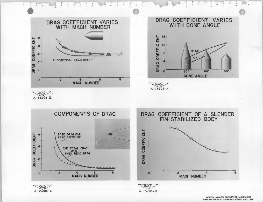
In this chart, test results are presented for a conical
nosed body, the included angle of the cone being 60°. The drag
coefficient is plotted against Mach number. The circles repre
~) sent data points. The average scatter of these points off the
••I
fared curve is about o.8 percent. The drag coefficient
decreases as the Mach number increases. However, it will be
remembered that the drag force is increasing rapidly with Mach
number due to the fact that the coefficient must be multiplied
by the Mach number squared.
The drag of a simple body of this type may be considered
as made up of three contributing parts: The head drag, which
is due to high pressures acting on the nose; the base drag,
which is due to low pressures behind the body; and the skin
friction, which is the frictional effect of the air on the body
surface.
The red curve represents the head drag for this cone
cylinder, and is computed from theory. To this, the base drag
and the skin friction must be added to get the total drag. It
is seen that head drag is the biggest part of the total drag
and that it largely determines the shape of the total drag curve.

-· ... This result is not general. It is true only for very blunt
nosed bodies. In this case, the head drag is such a large part
of the total that it would be expected that major reduction of
the drag coefficient could be brought about by changing head
shape. This is borne out experimentally as shown on the next
chart, where drag coefficient is plotted against cone angle.
It is seen that a radical reduction in drag coefficient results
from changing the cone angle. For example, at Mach number 3.7,
the 30° cone has less than one-fourth the drag of the 90° cone.
The base drag is a very important part of the drag of most
missile bodies, particularly at Mach numbers between 1 and 4.
The skin friction is also important in the case of long slender
bodies, because of the large amount of surface area over which
' ' the friction acts. In the case of the 60° cone cylinder the
base drag and skin friction are small parts of the total drag
but this is largely due to the fact that the 60° conical nose
is very inefficient and overshadows the other drag components.
The base drag and skin friction of this model can best be
examined on the next chart, where the difference between total
drag and head drag is plotted in coefficient form against Mach
number. Within the limits of errors in theory and experiment,
this curve represents the sum of the base drag and skin friction• . ...
The red curve is a plot of the maximum possible value of base
_,. drag, computed for zero pressure at the base, The actual value
of base drag must be less than this, and mu.at, in fact fall .,
below both curves. Estimates of the base drag of this model,
obtained by two different methods, are shown as points.

... A shadowgraph picture of a 60° cone cylinder moving at a
Mach number of 7 is included on this chart. The model image •
is somewhat distorted by the strong density gradients in the
air stream. The system of waves associated with the model,
and the wake of' the model can be seen• .. (
The next chart shows drag results f'or a slender, f'in
stabilized body. Again, drag coef'f'icient is plotted against .. ,_ Mach number. This curve, in which drag coefficient decreases
strongly with rising Mach number, is typical of bodies with
efficient noses, and represents a case where the base drag is
a controlling factor.
In summary, the supersonic free-flight wind tunnel is a
new piece of research equipment, capable of testing at Mach
numbers f'rom 1 to 15, at good scale.
Drag measurements have been presented on cone cylindrical' r
bodies and on a slender, fin-stabilized body, and an effort has
been made to break down the drag into its component parts.
This concludes our demonstration.
As you go to the bus, there may be a very loud noise due
to a demonstration of the l by 3 blowdown tunnel which is next
to the free-flight tunnel. Although this noise is very alarming,
there is no actual danger.

I
" •.(
-" l. ~ ~ • ... -4
"'
Display for Presentation of "Research at Higher Supersonic Speeds" by Supersonic Free-Flight Tunnel
NATIONAL ADVISORY COMMITTEE FOR AERONAUTICS AMES AcRONAUTICAl LABORATORY, MOFFETT FIELD, CALIF.
I ( _, I < ~ .. ~
.... .. ....... ... A ~ .... ,..
'
SABOT SEPARATES FROM MODEL SHADOWGRAPH
CHRONOGRAPH
~ ~ A-15208-A A- 15208-B
WIND TUNNEL COVERS THIS RANGE: DRAG PROHIBITIVE AT LOW ALTITUDE en~ 30 m...J _J 60
3'LLi 0
~
"'" 0 20 :::> (/) I- 0 40 z~ <( <( 10 (/) LL.I =>...J (i'j 0 20 (/) :c
~:i 0 10 20 30 40 .
MISSILE LENGTH. FEET C> <( 0::: 0 4 8 12 16 20 24 28 0
ALTITUDE. MILES
~
A-152 08-D
NATIONAL ADVISORY COMMITIEE FOR AERONAUTICS AMES AERONAUTICAL LABORATORY, MOFFETI FIELD, CALIF.
l r ,._ ,,_ " ~
DRAG COEFFICIENT VARIES WITH MACH NUMBER
I- 1.0 z I.LI 0 .8 ii: ' LL ~ -I.LI .6 ~- - , " - - - "-"' JI•
0 0 THEORETICAL HEAD DRAG.4 C> ct ~ .2
0 2 4 6 8 MACH NUMBER
COMPONENTS OF DRAG
1 BASE DRAG FOR ZERO PRESSURE
z .6 !:!:! /2 LLLL .4 I.I.I 0 0
~ .2
IX c
0 2 4 6 8 MACH NUMBER
~
'
DRAG COEFFICIENT VARIES WI TH CONE ANGLE
I- 1.6 z I.LI
0 1.2 LL LLI.LI .8 0 0 .4 C> ct IX c 0 30° so• 90°
CONE ANGLE
~ A-15208-F
DRAG COEFFICIENT OF A SLENDER FIN-STABILIZED BODY
1-
" -z I.I.I 0 ii: LL I.I.I
0 0 ~ -· ~ IX c
0 2 4 6 MACH NUMBER
NATIONAL ADVISORY COMMITTEE FOR AERONAUTICS AMES AERONAUTICAL LABORATORY, MOFFETT FIELD, CALIF.
~~ A-15208-G A-15208-H

... .
..
• >
.... >
.. .... .

y
•
' )
We will now illustrate this reduction in shock intensity
with a water channel which has a shape similar to this type of
nozzle.
The waves on the surface of the water are analogous to the
shock waves that occur in flow with supersonic velocity, These
waves that now occur at the test-section velocity correspond to
the terminal shock waves in a supersonic wind tunnel. As the
channel is adjusted to allow these waves to pass downstream of
the second throat the strength of the waves decreases.
The power required to operate a wind tunnel with this type
of diffuser is much less than that required when a straight
diverging diffuser is employed. To illustrate, for a wind tunnel
designed to operate at seven times the speed of sound, the power
required is cut in half.
This is the same type of diffUser and nozzle configuration
as employed in the 10- by 14-inch supersonic wind tunnel.
Mr. will now discuss the operation of this wind ~~~~~~
tunnel.

B. Description of the 10- by 14-inch Supersonic Wind Tunnel
... . The need for equipment to conduct research at high supei
sonic airspeeds has been emphasized by the recent development
of rocket-propelled missiles capable of flying at these speeds.
The German V-2 is a familiar missile of this type. As was
pointed out in the previous talk, many new problems are
encountered at high supersonic speeds. The wind tunnel is the
most efficient means of solving these problems experimentally.
For this reason, the Ames Laboratory has recently placed in
operation two wind tunnels - one is the supersonic free-flight
tunnel, and the other is the 10- by ll-1-inch supersonic wind
tunnel. I would now like to describe the latter tunnel to you.
This chart is a schematic diagram of the 10- by 14-inch
supersonic wind-tunnel building. You are now located in this
area facing toward the control panel. At the top is seen a
cutaway view of the wind tunnel. This tunnel is of the closed
throat, continuous-flow type. It can be operated at all speeds
from three to seven times the speed of sound. Centrifugal
compressors, located in the building at your left, supply air
to the tunnel through this pipe line. After passing through
the tunnel the air exhausts into either the boundary-layer scoo];B
or the main diffUser. The boundary-layer-scoop air passes
through these pipes and is drawn off by the rotary vacuum pumps
shown here. It is then discharged to the atmosphere. The air
in the main diffuser exhausts directly to the atmosphere through
this pipe at low test speeds. At high test speeds, the air is

directed through these centrifugal evacuators and then dis
charged to the atmosphere. You can see the main diffuser and
boundary-layer-scoop piping at your right. The maximum total
power required to operate the tunnel is 5700 horsepower.
From the control panel the tunnel operator has control of
all components of the tunnel and auxiliary equipment. Models
located in the test section are supported from the rear. Forces
and moments acting on them are measured with a conventional
strain-gage balance system. A sensitive optical system is used
to observe and photograph flow patterns about the models. The
mirrors in this system are shown here along with the path the
light beam follows. The image of the model and the flow about it
are observed on this screen.
This chart is a photograph of the 10- by lli-inch wind tunnel.
One side wall has been removed in order that the pertinent
features of the tunnel may be pointed out. The 10-inch dimension
refers to the width of the tunnel, which is constant; and the
lli-inch dimension refers to the nominal depth of the test section.
The tunnel is composed of a nozzle, a test section, and a
converging--diverging diffuser. You will remember from the pre
vious discussion of channel flows that this type of diffuser
was the more efficient for high supersonic speeds. The upper
and lower movable sections, referred to as nozzle blocks, are
identical and of rigid construction. The stationary side walls
are flat and parallel. The position of each block is controlled
by means of two independent sets of motor-driven jacks, one set

.. .
,. .
located at the first throat and the other at the second throat.
The jacks are rigidly attached to the side walls and pin
connected to the blocks. Each set is driven by a single motor
through identical drives to ensure symmetry of the blocks at
all times. By this means the blocks may be either translated
or rotated with respect to each other. With this mechanism,
the speed in the test section may be varied by changing the
ratio of first throat area to test area. As previously mentioned,
each block has a boundary-layer scoop at the second throat. The
purpose of these scoops is to stabilize the flow in the main
diffuser by removing the low-energy boundary--layer air. This
improves the main diffuser efficiency. The scoops are indepen
dently driven by small motors attached to the blocks to allow
for adjustments necessary with changes in tunnel speed.
Each nozzle bloc~including the scoop, is sealed from the
atmosphere by inflated seals adjacent to the air passage.
It may be of interest to mention the change in the first
throat and test.-section heights over the range of tunnel opera
tion. At the minimum test speed the first throat height is
~ inches and at the maximum speed it is 1/20 of an inch. The
corresponding test-section heights are 15 inches and 10 inches.
Instrumentation of the wind tunnel is, in general, of
conventional design. However, due to the high supersonic speeds
attained in the test section, very low pressures are encountered.
For example, the pressure drops to as low as 1/1000 of an atmos
phere. Conventional pressure measuring devices are inadequate

- .
r
- .. f
for measuring pressures of this magnitude. A special low-
pressure gage called the McLeod gage, was adopted for this
reason.
The air passing through the tunnel test section is also at
a very low density. Special X-ray equipment is being investi
gated for the purpose of determining this property of the air
stream.
The next chart compares the operating range of the 10- by
lli-inch wind tunnel with the conditions encountered by a V-2
rocket in flight. In the lower figure, the vertical scale is
altitude in miles. The horizontal scale is distance traveled
by the V-2, in miles. The solid line is the combat trajectory
of the V-2 from take-off to landing. The test conditions in
the wind tunnel are represented by the shaded area. In the
darkly shaded area the wind tunnel accurately duplicates the
aerodynamic conditions to which this rocket is subjected. In
the lightly shaded area the wind tunnel duplicates these con
ditions sufficiently well for most practical purposes since
the corresponding speeds are the same.
In the upper figure, you will notice that the horizontal
scale is unchanged. The vertical scale is now speed in miles
per hour. The solid line here shows the speeds attained by the
V-2 from take-off to landing. The speed range of the wind tunnel,
which is independent of distance, is shown by the rectangular
shaded area. You can see that except for a short distance just
after take-off, the flight of the V-2 takes place in the lower
speed range of the wind tunnel.

• •
In conclusion, it may be pointed out that the definite
advantage of this wind tunnel is its ability to operate at all
\ . speeds ranging from intermediate to high supersonic speeds.
This feature, coupled with the fact that conditions at typical
altitudes can be duplicated, makes the tunnel particularly
suited as an instrument for basic research - that is, research
on wings and bodies. It should also be pointed out, however,
that due to the small size of the tunnel, and, consequently,l •
the small size of the models that can be tested, this tunnel
is somewhat unsuited for development work.
Our program will conclude with a short motion picture
showing the changes with speed that occur in the flow field
about a typical model mounted in the 10- by 14-inch wind tunnel.
This next chart, which is a picture of the flow about this
model at three times the speed of sound or a Mach number of 31
will show you some of the points to be followed in the motion
picture. The speed of the wind tunnel at any instant can be
determined by noting where the bow shock wave crosses the
superimposed scales. You will notice that the lower scale
is the equivalent sea-level airspeed in miles per hour. The
upper scale denotes the Mach number. other points of interest
will be covered while the movie is in progress.
Movie.
This concludes the program of the 10- by 14-inch supersonic
wind tunnel. Thank you for your interest and attention.
_, ~ ... 4 .... "
"'(_ • ..~ ~ "' ( ~
•
PERFORMANCE OF IO"x 14" W. T. ::i: 6000. 0..,. ~ :3000.., 0.. V>
..; 0 ::>V>>- ..,i=_J ,.::::!
"'
IQ 'X .U illCtl c;ml.~•WJ• wnL!:> ~JurnI!.!.
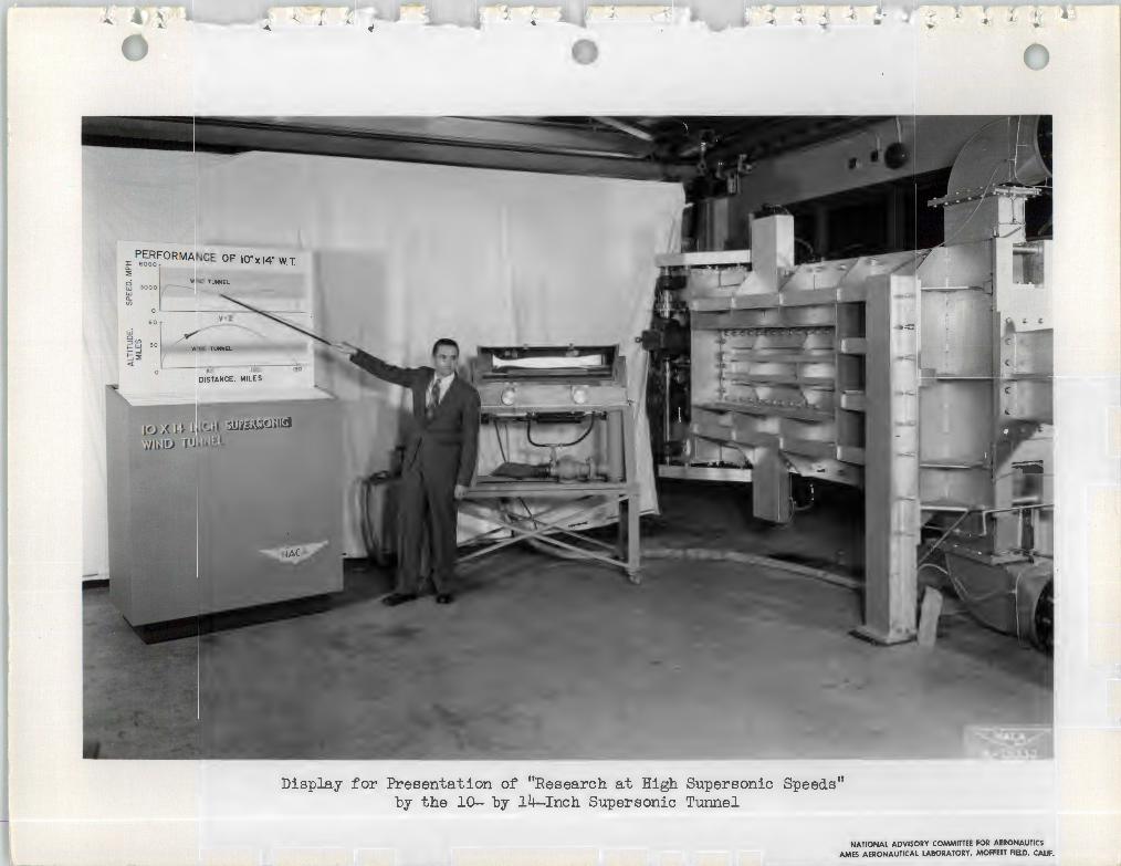
Display for Presentation of "Research at High Supersonic Speed.s" by the 10- by 14-Inch Supersonic Tunnel
NATIONAL ADVISORY COMMITTEE FOR AERONAUTICS AMES AERONAUTICAL LABORATORY, MOFFETT FIELD, CALIF.

-----
I ... ...; A ' A ....
FLOW CHANGES WITH SPEED STREAMLINES~
LOW SUBSONIC
SPEEDS
INTERMEDIATE .. ·-~>"-- ~- ..SUBSONIC - .... ~
SPEEDS
HIGH SUBSONIC
SPEEDS
~ A- 15 199-A
FRICTION REDUCES EFFICIENCY A** EXPERIMENTAL - - - - · THEORY WITHOUT FRICTION
LOW HIGH SUPERSONIC SUPERSONIC
(!) SPEED SPEED
<[a:: c
~
~1 ' _J /.
ANGLE OF ATTACK
~
, ,_ .. -< ..._. . .,,;. ....,
,,•
FLOW CHANGES WITH SPEED
LOW SUPERSONIC
SPEEDS
INTERMEDIATt.~ - ··. = SUPERSONIC~ s~~---:_,, ·~
SPEEDS -- · BOUNDARY L.AYER
HIGH SUPERSONIC NEAR VACUUM<HYPERSONIC)
SPEEDS HYPERSONIC BOUNDARY LAYER
~ A- 15 199-B
NOZZLE SHAPE CHANGES ~H SPEED
SUBSONIC ~ SPEEDS
LOW _ SUPERSONIC ~
SPEEDS (- I"" \
TERMINAL SHOCK WAVES
HIGH SUPERSONIC '-../ ~
SPEEDS --~____:_~~---------
~
A-15199- D
A-15199-C NATIONAL ADVISORY COMMITTEE FOR AERONAUTICS
AMES AERONAUTICAL LABORATORY, MOFFETI FIELD, CALIF.

.( ... J.~ A .\ _. • .. ' i).
-< ... ......._ l • .., .,, ... "'
~ A-15199-F
PERFORMANCE OF 1o·x 14· wt ~ 6000 MODEL IN WIND TUNNEL 0.. :E
~ 3000 w 0.. (/) ~.__~~~~v~-~2/-~~~~_J-w Cl :::> (/)1--W 30__. WIND TUNNllP • 1 T ) d. ~ ::?! <t
0 60 120 180
DISTANCE. MILES
NATIONAL ADVISORY COMMITTEE FOR AERONAUTICS AMES AERONAUTICAL LABORATORY, MOFFETI FIELD, CALIF.

----
.'
... INSIDE YOUR PRESS PACKET-
n,,_ .,..,. -• *'..,. ,_.....-1..i __,,_,. •r - .... ..--la___1..,. ......... ·-···lcllr. ....,, ... _l.o~o.u_.._. .. , ...._.nri..,.,._,. ________.-i--·--.i.. ---- ....."'·-rau.-.-...--1""" .,._,_ non.411'1" --....-"'.. _,....,
llATIC&\t==-=~i.:::-=.,,,.,. Pl!IUl,~Wr.
Ml'•,tllli!lllif.l ~
o.,ui.."" ~----.. - - vt... ._"" ~.1' .. -..ia.T•'- ..... ""-·•---1•-l0-"'1.._~-1.•--11•-la_.,._.,_
- -•.U ~...,. Olf - •t1-1 M.ot_,- -u.. '
-tloo. ----1·0,...10...,.U.,oopl~"'
(lot .. -1.coor .....1---.. ~ ................__.., ·-·
- ~- .... la'-\ -1-... u.-.i..-...- -
- - _,.w., ""1<1111 rill~ ..H u.r-U• - ,_
.....lpWl'!.<-.iaiH11M-a1......n.. -·.C\lt.lo-a.\a
,, 19'0•~~"' -.-ur'ICAL~-.t1'n<11o!JI, Cal•'-"'
hl;rllO-ll
"1!:' '"" ....., .... - .......... 1-11 u ..... "" ._ ~ M <lllo<- la to,.r .C A..!1141"1•.
,,,, ~~i!"~':..": :!.~!!:.' "
r ~,_____,_ ... __.._.... .,._. lll....&ldllk
~- .ii.... :c...Jillllll.,
"'-"'-l'W~r-.,n•.,,..._,.
._.....,..,,, . -·-·--· ~
A-15310
•n-.L,,.:i.=.m.~W::.,:-""lllll IO"ITl'!rmlll,O.UF,
rM•o,ICal!O.T J"1Jflll,l"°
A -- -..i. tn-ot wallll •-l to ....1<111-1"..,. n,.ir...--·--·....,.··-"-•--•0<&ll-........."'7
V1r>0-•-1.~ -u.. tor"""-"'"'"• •-1 ~-...-t-•-oa. ... otolf'<••-•U.O-v
-. --·· ~.<Xlll•U..•,..,. - •• - i....1.
,h,...,,.o ot._,.1-1 - 19'0 lao1190U• ot -· ~"'''7 ot
11ort.n J'ldol.,.... tolA t11n ...,., ..,. .,._,,It. t..ll•t.T, a.- ..
- _.,.,,,u 1-U-.t vllld •-1, will n••t •!4 M «pot.l<
., _..lac •• 1, ··-· _,. .............~ ... u.ooo ot - 1-lol. I• h<t, ..._lt1-l °"w1-t U ""lolc -- Whwa
•-t..~~t-llo.......U,""lolc-to
~ - -Int.. 0# aiuu...-cn- ..,.1-"'l- ot kltlll
... __i.r.•-otu.-•-11ou. -· ... ...,,,..
U.-lo-oal,l'ohY....,looot..~, .. .,.1t.1tlll\eo\ ..J901'1.o-··Oft -1-llJ.o, -lac - NMVok N""1•o ._...l,e t<>
ti..0ttort..-l&r•r-Jo. ri.tollooNl.o\1 ...l;j'k\.....M!tJof
...,. ur i. u.11 """' •-1, • u .... i.., -1 "''""' ••, _, ..-.
•n-.i. wn~ OOllln"mS..., -.naa
-~Cl<L~IO"ITl'!nzul,~
-----u.·~·ot--»-•l~
-.,.. ............... -- ... -c,.._"'"'"°
(i) Launchlnc;i QUn
@ Model In fllc;iht
@ Tlme-dlttance recording 1tollon1
@ Supersonic nozzle
@ Model cotcher
@Direction of olrstreom
~~-1o-lalaol-•_,.._...,u_..tM, ....o
---..u~~--i··--· _,Ml~....,--aa.. 11-tt-..-·•-
.... .............
a.--......-........ ""·--llor .... 1........
-·""1-ornci..q - ._-'- ... n,.,, _..""tt-.._,1 'IQ).U.•...---............ .....,n--0
"-..-••u-.i. "°-""7""..,. ••u..i. ...,_,. ~· rcr
,.._ .....,_.i ni.M, -·~· ,.....,,. - UOl,..l.rJ'
-1-o - "-" "'>1'11•- "" - la.,,,_.,.. •nreu<a
n..t.... - ............,.....- •• --·~""7--CA~-'-1~1a•u·clate, ...11 ......
- ..--. -""11'-7 ..... l ___u._
- -·· 1-iaJ. - .. _,.,.. -... ··-1.ao1-· W...1.8f7•• lll'JID '-"''• .....,_, , .... - ..... -·
...- ...-·.-~ ....-., ._.. la_u..r. rwn'- ""-- ..loo·--·_ ....,......,••....._ ... Ml.._-· hnlon reui._ Of .. _.,ftllloo - - UalU-·~·- .,..__. .....--·-·
""" - -• ''--"-'•lo - "-.I' ol --t Of
•l'hr<• •o .... --k - - ., ....,.u-~. U..,....tM ou,
Board, 36-. by 40-inches, di splayed in temporary press room on opening day (July 10) of 1950 Inspection .
NATIONAL ADVISORY COMMITTEE FOR AER0NAUT1 f"5 AMES At.RONAUTICAl lABORATOPY, MOFFETT FIELD r Al IJ