Embed Size (px)
Citation preview
Research ArticleSensor Module Based on the Wireless Sensor Network for theDynamic Stress on the Flexible Object with Large Deformation
Jinhui Zhao, Yi Zhuang, Jingjing Gu, Yan Xu, and Jian Sun
College of Computer Science and Technology, Nanjing University of Aeronautics and Astronautics, Nanjing 210016, China
Correspondence should be addressed to Yi Zhuang; [email protected]
Received 14 December 2015; Revised 1 April 2016; Accepted 19 April 2016
Academic Editor: Alberto J. Palma
Copyright © 2016 Jinhui Zhao et al. This is an open access article distributed under the Creative Commons Attribution License,which permits unrestricted use, distribution, and reproduction in any medium, provided the original work is properly cited.
When we are measuring the dynamic stress on flexible objects with large deformation, for example, the parachute, the morphologicstructure of the tested objects changes rapidly and sharply, and the measurement is conducted in a poor and variable environment.Traditional measuring methods cannot ensure credibility, repeatability, and high precision of the test. This paper introduces stresssensor module based on the wireless sensor network for the flexible objects with large deformation. In this paper, the wirelesssensor network works as the signal transmitting carrier and the Ω sensor is improved. In addition, the paper further studies theeffect of module deployment on the flexible objects with large deformation and the effect of experiment environment on the sensortest. Finally, the compensation method is proposed and measurement reliability is improved. The performance experiments of thesensor verify the availability and repeatability of the dynamic sensor module. The drop experiment of the small parachute and thewind tunnel experiment prove that the sensormodule can effectivelymeasure the stress on the flexible object with large deformationand the results accord with the parachute canopy stress rule.
1. Introduction
With the development of modern industrial technology, theflexible fabric with large deformation has been widely used.However, it is difficult to measure and analyze its stress whenit is working. Deformation of the flexible object happensinstantly at a high speed. During this process, the materialshape changes dramatically. The mechanical distributioncharacteristics, material strength, and elongation are quitedifferent from those in the static state. At present, no methodcan calculate the exact stress in the deformation process.The analysis and verification in the designing process of theparachute mainly depend on experiments [1–5]. However,current measurement methods are not suitable for largedeformation and can be used only for qualitative analyses [6].
Current measurement methods mainly use the wiredtransmit of signals.The wire deployment will affect the shapeof the flexible object. In particular, for big-size flexible objects,the deployment becomesmore difficult and the overlongwiremay weaken the signals and affect the measure effects. Asa distributed sensor network, the terminal of the wireless
sensor network (WSN) is a type of sensor that can perceiveand inspect the outside world. As sensors in the WSNcommunicate in the wireless mode, the network settings areflexible and device positions can be changed at any time.Using theWSNas the transmitting carrier of signals can effec-tively reduce the sensor layout impact on the tested object inthe wired mode [7]. Besides, the signal transmitting distancein the WSN can reach thousands of meters, which can dealwith the distance restrictions during the wired transmission.
Against these problems, this paper proposes Ω-type sen-sor module and conducts an in-depth study and analysis ofvarious factors in the measurement. Besides, a compensationmethod is proposed to accurately measure the workingprocess of the flexible fabric with large deformation.
2. Related Work
Over the past years, researchers have studied the dynamicstress on the flexible objects with large deformation. In the1960s, the US army measured the pressure on the parachutecanopy surface with a strain pressure sensor [8, 9]. However,
Hindawi Publishing CorporationJournal of SensorsVolume 2016, Article ID 1368309, 11 pageshttp://dx.doi.org/10.1155/2016/1368309
2 Journal of Sensors
Table 1: Comparisons among current test methods.
Sensor type Weight (g) Core idea Influence of layouttechnique
Influence oftemperature Experiment type
Strain pressuresensor [8] 5.67 Stress change on the
fabric surfaceGreat but not
handled
Temperatureinfluence considered
and half-bridgetemperaturecompensated
Low-speed windtunnel experiment
and dropexperiment
Ω-type sensor[10] 2.7 Good structure for
stress transmittingRelatively great but
not handled
Temperatureinfluence consideredand strain gaugecompensated
Drop experimentand low-speedwind tunnelexperiment
CPC compositematerial sensor[1, 11]
≤1.2The storage device isdeployed on thesurface of theparachuteWeight: 10 g
Stress change on thefabric surface
Limited andcompensated on
the coatingthickness
Not compensated;subzero temperature
not analyzedDrop experiment
Fiber sensor[12, 13] Uncertain
Stress change testedby fiber deformation
level
Limited and nothandled
Temperatureinfluence consideredand strain gaugecompensated
Drop experiment
Improved Ωtype sensormodule (IOS)
2.2Compensation on theinfluencing during
the test
There is influencebut it is
compensated
Temperatureinfluence considered
and full-bridgetemperaturecompensated
Drop experimentand low-speedwind tunnelexperiment
limited by the sensor deployment and sensor capabilities,the experimental result could not satisfy the requirement ofaccuracy. In the 1970s, for the first time, NASA proposedthat the parachute canopy stress could be measured usingthe wired sensor. During the experiment, Ω sensor wasadopted to measure the parachute canopy fabric. However,due to technology limitations, the experiment just conducteda qualitative analysis of deployment of the parachute canopyunder the air flow [10].
Since 2007, French Textile Materials and EngineeringLaboratory proposed a CPC composite material sensor tomeasure flexible objects. This method provided a new idea.However, because of the unsatisfactory ductility of the mate-rial, they just conducted the static test [11]. Till 2010, thelaboratory made some improvements in the CPC compositematerial sensor, analyzed the temperature influence, sensoraging, and repeatability, and implemented a small-scale droptest. However, material ductility was still a problem [1].
Since 2009, NASA has been using the fiber sensor tomeasure the parachute canopy stress. However, due to thelimited ductility of fiber materials, the experiment can onlymeasure small deformation. In 2010, Beijing Institute of SpaceMachinery and Electronics (BISME) improved the fibersensor and applied it to the test of parachute canopy.However,due to the problems of cross sensitivity of temperature andstrain and poor antishear ability, the fiber sensor could notsatisfy the requirement of wind tunnel experiment [12].
In conclusion, current researches have provided multiplesolutions to the measurement of stress on the flexible objectwith large deformation and made some progress. However,
problems of limited ductility and layout technique as wellas environmental factors which can affect the experimentstill exist. On account of all the mentioned difficulties anddeficiencies of technology, this paper proposes a sensormodule based on the wireless sensor network for the stresson the flexible object with large deformation. Through theimproved Ω-type sensor, the fabric stress change can be welldetected and the data can be transmitted through the wirelesssensor network. Therefore, the data will be compensated andstudied.The parachute is taken as a typical application for theexperiment and verification. The performance comparisonamong current methods and the sensor module is shownin Table 1. In the table, the “drop experiment” means realopening from the bag to stabilized descent.
3. Design of the Sensor Module
The measurement of the stress on the flexible object withlarge deformation can be represented by the convertingprocess from the stress signal to electrical signal. To ensurecorrectness and accuracy, the sensor should possess a goodstress transmitting structure to reduce stress loss during thetransmitting process. Then the sensor will convert the stresssignal and eliminate the external influence and interferenceon the sensor and try to amplify the signal to make iteasier to be received, processed, and delivered. Hence, thesensor module for the flexible object with large deformationis proposed. The model consists of the Ω sensor part andauxiliary circuit part. The Ω sensor part comprises thestress transmitting structure, which is the Ω-type media and
Journal of Sensors 3
1/4
5/8
Nylon cloth tabs, MIL-C-7020,type IAdhesive Duco cement
Curved beam
Strain gauges
Force
Temp comp
Parachute gore
Gore centerline
Σ
Σ
Σ
Σ
(a)
Full-bridge temperaturecompensation strain gauge
Welding point
Sensor placement hole
Ω-type media
(b)
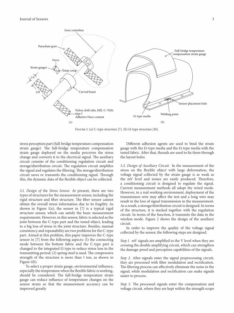
Figure 1: (a) C-type structure [7]. (b)Ω-type structure [10].
stress perception part (full-bridge temperature compensationstrain gauge). The full-bridge temperature compensationstrain gauge deployed on the media perceives the stresschange and converts it to the electrical signal. The auxiliarycircuit consists of the conditioning regulation circuit andstorage/distribution circuit. The regulation circuit amplifiesthe signal and regulates the filtering.The storage/distributioncircuit saves or transmits the conditioning signal. Throughthis, the dynamic data of the flexible object can be collected.
3.1. Design of the Stress Sensor. At present, there are twotypes of structures for the measurement sensor, including therigid structure and fiber structure. The fiber sensor cannotobtain the overall stress information due to its fragility. Asshown in Figure 1(a), the sensor in [7] is a typical rigidstructure sensor, which can satisfy the basic measurementrequirements. However, in this sensor, fabric is selected as thejoint between the C-type part and the tested object, leadingto a big loss of stress in the joint structure. Besides, manualconsistency and repeatability are two problems for the C-typepart. Aimed at this problem, this paper improves the C-typesensor in [7] from the following aspects: (1) the connectingmode between the bottom fabric and the C-type part ischanged to the integrated Ω type to reduce stress loss in thetransmitting period; (2) spring steel is used. The compressivestrength of the structure is more than 1 ton, as shown inFigure 1(b).
To select a proper strain gauge, environmental influence,especially the temperaturewhen the flexible fabric is working,should be considered. The full-bridge temperature straingauge can reduce influence of temperature changes on thesensor strain so that the measurement accuracy can beimproved greatly.
Different adhesion agents are used to bind the straingauge with theΩ-type media and the Ω-type media with thetested fabric. After that, threads are used to fix them throughthe layout holes.
3.2. Design of Auxiliary Circuit. In the measurement of thestress on the flexible object with large deformation, thevoltage signal collected by the strain gauge is as weak asthe mV level and noises are easily produced. Therefore,a conditioning circuit is designed to regulate the signal.Current measurement methods all adopt the wired mode.However, in a real working environment, deployment of thetransmission wire may affect the test and a long wire mayresult in the loss of signal transmission in the measurement.As a result, a storage/distribution circuit is designed. In termsof the structure, it is stacked together with the regulationcircuit. In terms of the function, it transmits the data in thewireless mode. Figure 2 shows the design of the auxiliarycircuit.
In order to improve the quality of the voltage signalcollected by the sensor, the following steps are designed.
Step 1. mV signals are amplified to the V level when they arecrossing the double amplifying circuit, which can strengthenthe damage-proof and perception capabilities of the signals.
Step 2. After signals enter the signal preprocessing circuit,they are processed with filter modulation and rectification.The filtering process can effectively eliminate the noise in thesignal, while modulation and rectification can make signalseasier to process.
Step 3. The processed signals enter the compensation andvoltage circuit, where they are kept within the strength scope
4 Journal of Sensors
Primaryamplification
Secondaryamplification
Signalpreprocessing
A/Dconverter
Storage/distributioncircuit
Power supplier
VoltagefollowerRegulate
circuit
SignalΩ sensor
Figure 2: Auxiliary circuit of the sensor module.
set at the A/D convert circuit. Through this step, the loss inthe transmitting process will be effectively compensated for.
Step 4. The simulated signals are converted to digital signalsthrough the A/D converter and saved or delivered accordingto the final demand.
The signal auxiliary circuit mentioned above can effec-tively improve the quality of signals, reduce the loss of signalsduring the transmitting process, and make it easier to get theprocessed signals in subsequent circuits.
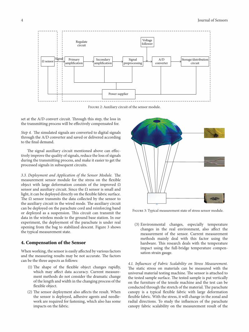
3.3. Deployment and Application of the Sensor Module. Themeasurement sensor module for the stress on the flexibleobject with large deformation consists of the improved Ωsensor and auxiliary circuit. Since the Ω sensor is small andlight, it can be deployed directly on the flexible fabric surface.The Ω sensor transmits the data collected by the sensor tothe auxiliary circuit in the wired mode. The auxiliary circuitcan be deployed on the parachute cord and reinforcing bandor deployed as a suspension. This circuit can transmit thedata in the wireless mode to the ground base station. In ourexperiment, the deployment of the parachute is under realopening from the bag to stabilized descent. Figure 3 showsthe typical measurement state.
4. Compensation of the Sensor
Whenworking, the sensor is easily affected by various factorsand the measuring results may be not accurate. The factorscan be the three aspects as follows:
(1) The shape of the flexible object changes rapidly,which may affect data accuracy. Current measure-ment methods do not consider the dramatic changeof the length and width in the changing process of theflexible object.
(2) The sensor deployment also affects the result. Whenthe sensor is deployed, adhesive agents and needle-work are required for fastening, which also has someimpacts on the fabric.
Figure 3: Typical measurement state of stress sensor module.
(3) Environmental changes, especially temperaturechanges in the real environment, also affect themeasurement of the sensor. Current measurementmethods mainly deal with this factor using thehardware. This research deals with the temperatureimpact using the full-bridge temperature compen-sation strain gauge.
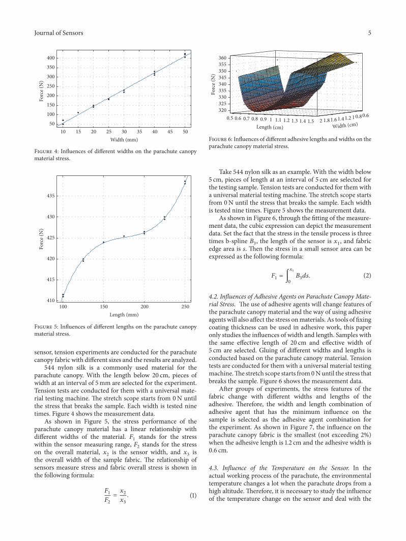
4.1. Influences of Fabric Scalability on Stress Measurement.The static stress on materials can be measured with theuniversal material testing machine. The sensor is attached tothe tested sample surface. The tested sample is put verticallyon the furniture of the tensile machine and the test can beconducted through the stretch of the material. The parachutecanopy is a typical flexible fabric with large deformationflexible fabric. With the stress, it will change in the zonal andradial directions. To study the influences of the parachutecanopy fabric scalability on the measurement result of the
Journal of Sensors 5
10 15 20 25 30 35 40 45 50Width (mm)
50
100
150
200
250
300
350
400
Forc
e (N
)
Figure 4: Influences of different widths on the parachute canopymaterial stress.
100 150 200 250Length (mm)
410
415
420
425
430
435
Forc
e (N
)
Figure 5: Influences of different lengths on the parachute canopymaterial stress.
sensor, tension experiments are conducted for the parachutecanopy fabric with different sizes and the results are analyzed.
544 nylon silk is a commonly used material for theparachute canopy. With the length below 20 cm, pieces ofwidth at an interval of 5mm are selected for the experiment.Tension tests are conducted for them with a universal mate-rial testing machine. The stretch scope starts from 0N untilthe stress that breaks the sample. Each width is tested ninetimes. Figure 4 shows the measurement data.
As shown in Figure 5, the stress performance of theparachute canopy material has a linear relationship withdifferent widths of the material. 𝐹
1stands for the stress
within the sensor measuring range, 𝐹2stands for the stress
on the overall material, 𝑥2is the sensor width, and 𝑥
3is
the overall width of the sample fabric. The relationship ofsensors measure stress and fabric overall stress is shown inthe following formula:
𝐹1
𝐹2
=𝑥2
𝑥3
. (1)
0.60.811.21.41.61.820.5 0.6 0.7 0.8 0.9 1 1.1 1.2 1.3 1.4 1.5
320325330335340345350355360
Width (cm)Length (cm)
Forc
e (N
)
Figure 6: Influences of different adhesive lengths and widths on theparachute canopy material stress.
Take 544 nylon silk as an example. With the width below5 cm, pieces of length at an interval of 5 cm are selected forthe testing sample. Tension tests are conducted for them witha universal material testing machine. The stretch scope startsfrom 0N until the stress that breaks the sample. Each widthis tested nine times. Figure 5 shows the measurement data.
As shown in Figure 6, through the fitting of the measure-ment data, the cubic expression can depict the measurementdata. Set the fact that the stress in the tensile process is threetimes b-spline 𝐵
3, the length of the sensor is 𝑥
1, and fabric
edge area is 𝑠. Then the stress in a small sensor area can beexpressed as the following formula:
𝐹1= ∫
𝑥1
0
𝐵3𝑑𝑠. (2)
4.2. Influences of Adhesive Agents on Parachute Canopy Mate-rial Stress. The use of adhesive agents will change features ofthe parachute canopy material and the way of using adhesiveagents will also affect the stress onmaterials. As tools of fixingcoating thickness can be used in adhesive work, this paperonly studies the influences of width and length. Samples withthe same effective length of 20 cm and effective width of5 cm are selected. Gluing of different widths and lengths isconducted based on the parachute canopy material. Tensiontests are conducted for them with a universal material testingmachine.The stretch scope starts from0Nuntil the stress thatbreaks the sample. Figure 6 shows the measurement data.
After groups of experiments, the stress features of thefabric change with different widths and lengths of theadhesive. Therefore, the width and length combination ofadhesive agent that has the minimum influence on thesample is selected as the adhesive agent combination forthe experiment. As shown in Figure 7, the influence on theparachute canopy fabric is the smallest (not exceeding 2%)when the adhesive length is 1.2 cm and the adhesive width is0.6 cm.
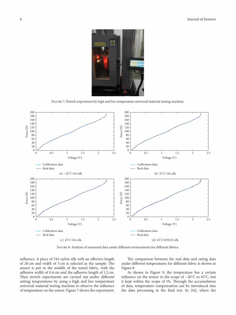
4.3. Influence of the Temperature on the Sensor. In theactual working process of the parachute, the environmentaltemperature changes a lot when the parachute drops from ahigh altitude. Therefore, it is necessary to study the influenceof the temperature change on the sensor and deal with the
6 Journal of Sensors
Figure 7: Stretch experiment by high and low temperature universal material testing machine.
0.5 1 1.5 2 2.50Voltage (V)
020406080
100120140160180200
Forc
e (N
)
Calibration dataReal data
(a) −10∘C 544 silk
0.5 1 1.5 2 2.50Voltage (V)
020406080
100120140160180200
Forc
e (N
)
Calibration dataReal data
(b) 25∘C 544 silk
020406080
100120140160180200
Forc
e (N
)
0.5 1 1.5 2 2.50Voltage (V)
Calibration dataReal data
(c) 45∘C 544 silk
0.5 1 1.5 2 2.50Voltage (V)
020406080
100120140160180200
Forc
e (N
)
Calibration dataReal data
(d) 65∘C K59225 silk
Figure 8: Analysis of measured data under different environments for different fabrics.
influence. A piece of 544 nylon silk with an effective lengthof 20 cm and width of 5 cm is selected as the sample. Thesensor is put in the middle of the tested fabric, with theadhesive width of 0.6 cm and the adhesive length of 1.2 cm.Then stretch experiments are carried out under differentsetting temperatures by using a high and low temperatureuniversal material testing machine to observe the influenceof temperature on the sensor. Figure 7 shows the experiment.
The comparison between the real data and rating dataunder different temperatures for different fabric is shown inFigure 8.
As shown in Figure 9, the temperature has a certaininfluence on the sensor in the scope of −20∘C to 65∘C, butit kept within the scope of 1%. Through the accumulationof data, temperature compensation can be introduced intothe data processing in the final test. In [14], where the
Journal of Sensors 7
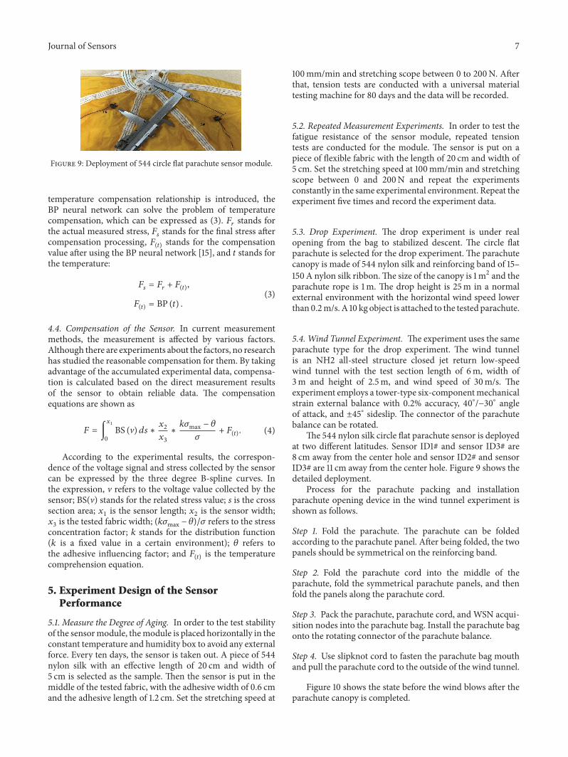
Figure 9: Deployment of 544 circle flat parachute sensor module.
temperature compensation relationship is introduced, theBP neural network can solve the problem of temperaturecompensation, which can be expressed as (3). 𝐹
𝑟stands for
the actual measured stress, 𝐹𝑠stands for the final stress after
compensation processing, 𝐹(𝑡)
stands for the compensationvalue after using the BP neural network [15], and 𝑡 stands forthe temperature:
𝐹𝑠= 𝐹𝑟+ 𝐹(𝑡),
𝐹(𝑡)= BP (𝑡) .
(3)
4.4. Compensation of the Sensor. In current measurementmethods, the measurement is affected by various factors.Although there are experiments about the factors, no researchhas studied the reasonable compensation for them. By takingadvantage of the accumulated experimental data, compensa-tion is calculated based on the direct measurement resultsof the sensor to obtain reliable data. The compensationequations are shown as
𝐹 = ∫
𝑥1
0
BS (V) 𝑑𝑠 ∗𝑥2
𝑥3
∗𝑘𝜎max − 𝜃
𝜎+ 𝐹(𝑡). (4)
According to the experimental results, the correspon-dence of the voltage signal and stress collected by the sensorcan be expressed by the three degree B-spline curves. Inthe expression, V refers to the voltage value collected by thesensor; BS(V) stands for the related stress value; 𝑠 is the crosssection area; 𝑥
1is the sensor length; 𝑥
2is the sensor width;
𝑥3is the tested fabric width; (𝑘𝜎max − 𝜃)/𝜎 refers to the stress
concentration factor; 𝑘 stands for the distribution function(𝑘 is a fixed value in a certain environment); 𝜃 refers tothe adhesive influencing factor; and 𝐹
(𝑡)is the temperature
comprehension equation.
5. Experiment Design of the SensorPerformance
5.1. Measure the Degree of Aging. In order to the test stabilityof the sensormodule, themodule is placed horizontally in theconstant temperature and humidity box to avoid any externalforce. Every ten days, the sensor is taken out. A piece of 544nylon silk with an effective length of 20 cm and width of5 cm is selected as the sample. Then the sensor is put in themiddle of the tested fabric, with the adhesive width of 0.6 cmand the adhesive length of 1.2 cm. Set the stretching speed at
100mm/min and stretching scope between 0 to 200N. Afterthat, tension tests are conducted with a universal materialtesting machine for 80 days and the data will be recorded.
5.2. Repeated Measurement Experiments. In order to test thefatigue resistance of the sensor module, repeated tensiontests are conducted for the module. The sensor is put on apiece of flexible fabric with the length of 20 cm and width of5 cm. Set the stretching speed at 100mm/min and stretchingscope between 0 and 200N and repeat the experimentsconstantly in the same experimental environment. Repeat theexperiment five times and record the experiment data.
5.3. Drop Experiment. The drop experiment is under realopening from the bag to stabilized descent. The circle flatparachute is selected for the drop experiment. The parachutecanopy is made of 544 nylon silk and reinforcing band of 15–150A nylon silk ribbon.The size of the canopy is 1m2 and theparachute rope is 1m. The drop height is 25m in a normalexternal environment with the horizontal wind speed lowerthan 0.2m/s. A 10 kg object is attached to the tested parachute.
5.4. Wind Tunnel Experiment. The experiment uses the sameparachute type for the drop experiment. The wind tunnelis an NH2 all-steel structure closed jet return low-speedwind tunnel with the test section length of 6m, width of3m and height of 2.5m, and wind speed of 30m/s. Theexperiment employs a tower-type six-componentmechanicalstrain external balance with 0.2% accuracy, 40∘/−30∘ angleof attack, and ±45∘ sideslip. The connector of the parachutebalance can be rotated.
The 544 nylon silk circle flat parachute sensor is deployedat two different latitudes. Sensor ID1# and sensor ID3# are8 cm away from the center hole and sensor ID2# and sensorID3# are 11 cm away from the center hole. Figure 9 shows thedetailed deployment.
Process for the parachute packing and installationparachute opening device in the wind tunnel experiment isshown as follows.
Step 1. Fold the parachute. The parachute can be foldedaccording to the parachute panel. After being folded, the twopanels should be symmetrical on the reinforcing band.
Step 2. Fold the parachute cord into the middle of theparachute, fold the symmetrical parachute panels, and thenfold the panels along the parachute cord.
Step 3. Pack the parachute, parachute cord, and WSN acqui-sition nodes into the parachute bag. Install the parachute bagonto the rotating connector of the parachute balance.
Step 4. Use slipknot cord to fasten the parachute bag mouthand pull the parachute cord to the outside of the wind tunnel.
Figure 10 shows the state before the wind blows after theparachute canopy is completed.
8 Journal of Sensors
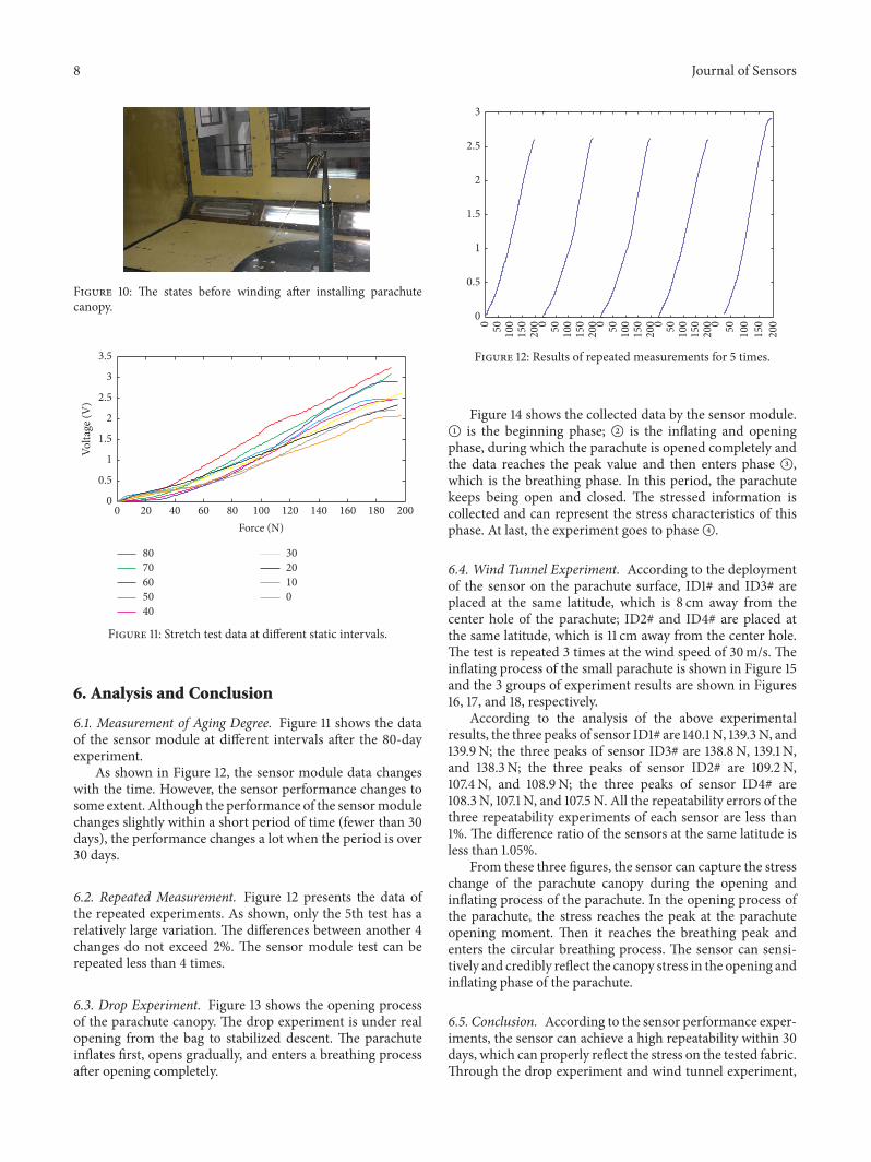
Figure 10: The states before winding after installing parachutecanopy.
8070605040
3020100
20 40 60 80 100 120 140 160 180 2000Force (N)
0
0.5
1
1.5
2
2.5
3
3.5
Volta
ge (V
)
Figure 11: Stretch test data at different static intervals.
6. Analysis and Conclusion
6.1. Measurement of Aging Degree. Figure 11 shows the dataof the sensor module at different intervals after the 80-dayexperiment.
As shown in Figure 12, the sensor module data changeswith the time. However, the sensor performance changes tosome extent. Although the performance of the sensormodulechanges slightly within a short period of time (fewer than 30days), the performance changes a lot when the period is over30 days.
6.2. Repeated Measurement. Figure 12 presents the data ofthe repeated experiments. As shown, only the 5th test has arelatively large variation. The differences between another 4changes do not exceed 2%. The sensor module test can berepeated less than 4 times.
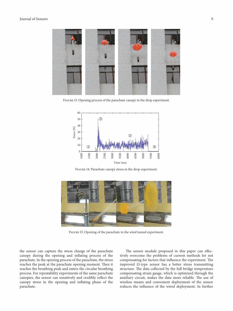
6.3. Drop Experiment. Figure 13 shows the opening processof the parachute canopy. The drop experiment is under realopening from the bag to stabilized descent. The parachuteinflates first, opens gradually, and enters a breathing processafter opening completely.
0 50 100
150
200 0 50 100
150
200 0 50 100
150
200 0 50 100
150
200 0 50 100
150
2000
0.5
1
1.5
2
2.5
3
Figure 12: Results of repeated measurements for 5 times.
Figure 14 shows the collected data by the sensor module.A is the beginning phase; B is the inflating and openingphase, during which the parachute is opened completely andthe data reaches the peak value and then enters phase C,which is the breathing phase. In this period, the parachutekeeps being open and closed. The stressed information iscollected and can represent the stress characteristics of thisphase. At last, the experiment goes to phaseD.
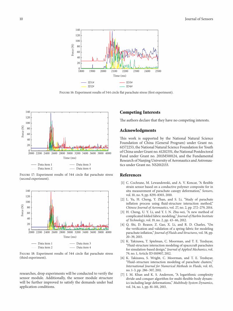
6.4. Wind Tunnel Experiment. According to the deploymentof the sensor on the parachute surface, ID1# and ID3# areplaced at the same latitude, which is 8 cm away from thecenter hole of the parachute; ID2# and ID4# are placed atthe same latitude, which is 11 cm away from the center hole.The test is repeated 3 times at the wind speed of 30m/s. Theinflating process of the small parachute is shown in Figure 15and the 3 groups of experiment results are shown in Figures16, 17, and 18, respectively.
According to the analysis of the above experimentalresults, the three peaks of sensor ID1# are 140.1 N, 139.3N, and139.9N; the three peaks of sensor ID3# are 138.8N, 139.1 N,and 138.3N; the three peaks of sensor ID2# are 109.2N,107.4N, and 108.9N; the three peaks of sensor ID4# are108.3N, 107.1 N, and 107.5N. All the repeatability errors of thethree repeatability experiments of each sensor are less than1%. The difference ratio of the sensors at the same latitude isless than 1.05%.
From these three figures, the sensor can capture the stresschange of the parachute canopy during the opening andinflating process of the parachute. In the opening process ofthe parachute, the stress reaches the peak at the parachuteopening moment. Then it reaches the breathing peak andenters the circular breathing process. The sensor can sensi-tively and credibly reflect the canopy stress in the opening andinflating phase of the parachute.
6.5. Conclusion. According to the sensor performance exper-iments, the sensor can achieve a high repeatability within 30days, which can properly reflect the stress on the tested fabric.Through the drop experiment and wind tunnel experiment,
Journal of Sensors 9
Figure 13: Opening process of the parachute canopy in the drop experiment.
1000
1500
2000
2500
3000
3500
4000
4500
5000
5500
6000
Time (ms)
0
10
20
30
40
50
60
Forc
e (N
)
1 4
2
3
Figure 14: Parachute canopy stress in the drop experiment.
Figure 15: Opening of the parachute in the wind tunnel experiment.
the sensor can capture the stress change of the parachutecanopy during the opening and inflating process of theparachute. In the opening process of the parachute, the stressreaches the peak at the parachute opening moment. Then itreaches the breathing peak and enters the circular breathingprocess. For repeatability experiments of the same parachutecanopies, the sensor can sensitively and credibly reflect thecanopy stress in the opening and inflating phase of theparachute.
The sensor module proposed in this paper can effec-tively overcome the problems of current methods for notcompensating for factors that influence the experiment. Theimproved Ω-type sensor has a better stress transmittingstructure. The data collected by the full-bridge temperaturecompensating strain gauge, which is optimized through theauxiliary circuit, makes the data more reliable. The use ofwireless means and convenient deployment of the sensorreduces the influence of the wired deployment. In further
10 Journal of Sensors
0
20
40
60
80
100
120
140
Forc
e (N
)
ID1#ID2#
ID3#ID4#
1900 2000 2100 2200 2300 2400 25001800Time (ms)
Figure 16: Experiment results of 544 circle flat parachute stress (first experiment).
0
20
40
60
80
100
120
140
Forc
e (N
)
Data item 4Data item 3
Data item 2Data item 1
2200 2400 2600 2800 3000 3200 3400 3600 3800 40002000Time (ms)
Figure 17: Experiment results of 544 circle flat parachute stress(second experiment).
2200 2400 2600 2800 3000 3200 3400 3600 3800 40002000Time (ms)
0
20
40
60
80
100
120
140
Forc
e (N
)
Data item 4Data item 3
Data item 2Data item 1
Figure 18: Experiment results of 544 circle flat parachute stress(third experiment).
researches, drop experiments will be conducted to verify thesensor module. Additionally, the sensor module structurewill be further improved to satisfy the demands under badapplication conditions.
Competing Interests
The authors declare that they have no competing interests.
Acknowledgments
This work is supported by the National Natural ScienceFoundation of China (General Program) under Grant no.61572253, the National Natural Science Foundation for Youthof China under Grant no. 61202351, theNational PostdoctoralFund under Grant no. 2011M500124, and the FundamentalResearch of NanjingUniversity of Aeronautics andAstronau-tics under Grant no. NS2012133.
References
[1] C. Cochrane, M. Lewandowski, and A. V. Koncar, “A flexiblestrain sensor based on a conductive polymer composite for insitu measurement of parachute canopy deformation,” Sensors,vol. 10, no. 9, pp. 8291–8303, 2010.
[2] L. Yu, H. Cheng, Y. Zhan, and S. Li, “Study of parachuteinflation process using fluid-structure interaction method,”Chinese Journal of Aeronautics, vol. 27, no. 2, pp. 272–279, 2014.
[3] H. Cheng, U. Y. Li, and Y. I. N. Zhu-wei, “A new method ofcomplicated folded fabric modeling,” Journal of Harbin Instituteof Technology, vol. 19, no. 2, pp. 43–46, 2012.
[4] Q. Shi, D. Reasor, Z. Gao, X. Li, and R. D. Charles, “Onthe verification and validation of a spring fabric for modelingparachute inflation,” Journal of Fluids and Structures, vol. 58, pp.20–39, 2015.
[5] K. Takizawa, T. Spielman, C. Moorman, and T. E. Tezduyar,“Fluid-structure interaction modeling of spacecraft parachutesfor simulation-based design,” Journal of Applied Mechanics, vol.79, no. 1, Article ID 010907, 2012.
[6] K. Takizawa, S. Wright, C. Moorman, and T. E. Tezduyar,“Fluid–structure interaction modeling of parachute clusters,”International Journal for Numerical Methods in Fluids, vol. 65,no. 1–3, pp. 286–307, 2011.
[7] I. M. Khan and K. S. Anderson, “A logarithmic complexitydivide-and-conquer algorithm for multi-flexible-body dynam-ics including large deformations,”Multibody System Dynamics,vol. 34, no. 1, pp. 81–101, 2015.
Journal of Sensors 11
[8] I. M. Khan, W. Ahn, K. S. Anderson, and S. De, “A logarithmiccomplexity floating frame of reference formulation with inter-polating splines for articulated multi-flexible-body dynamics,”International Journal of Non-Linear Mechanics, vol. 57, pp. 146–153, 2013.
[9] T. Zheng and D.-G. Zhang, “Limitations of MSC. ADAMS forhigh-speed and large deformation problems of rigid-flexiblecoupling systems,” Journal of Nanjing University of Science andTechnology, vol. 36, no. 6, pp. 993–998, 2012.
[10] H. G. Heinrich and D. P. Saari, “Parachute canopy stressmeasurements at steady state and during inflation,” Journal ofAircraft, vol. 15, no. 8, pp. 534–539, 1978.
[11] C. Cochrane, V. Koncar, M. Lewandowski, and C. Dufour,“Design and development of a flexible strain sensor for textilestructures based on a conductive polymer composite,” Sensors,vol. 7, no. 4, pp. 473–492, 2007.
[12] M. Tang andM. Zhu, “Ameasurement of flexible filled structurestress and strain of new type of sensor system,” in 23th NationalSpace Exploration Abstract Set of Academic Exchange, 2010.
[13] J. Bazin and T. D. Fields, “Validation and flight testing of awireless load distribution measuring system,” in Proceedingsof the 23rd AIAA Aerodynamic Decelerator Systems TechnologyConference, Aerodynamic Decelerator Systems Technology Con-ferences, AIAA 2015-2120, Daytona Beach, Fla, USA, 2015.
[14] S. A. Khan, T. Islam, and G. Husain, “Artificial neural networkbased online sensor calibration and compensation,” Interna-tional Journal of Computing, vol. 6, no. 3, pp. 74–78, 2014.
[15] R. Song, X. Chen, C. Shen, and H. Zhang, “Modeling FOG driftusing back-propagation neural network optimized by artificialfish swarm algorithm,” Journal of Sensors, vol. 2014, Article ID273043, 6 pages, 2014.

International Journal of
AerospaceEngineeringHindawi Publishing Corporationhttp://www.hindawi.com Volume 2014
RoboticsJournal of
Hindawi Publishing Corporationhttp://www.hindawi.com Volume 2014
Hindawi Publishing Corporationhttp://www.hindawi.com Volume 2014
Active and Passive Electronic Components
Control Scienceand Engineering
Journal of
Hindawi Publishing Corporationhttp://www.hindawi.com Volume 2014
International Journal of
RotatingMachinery
Hindawi Publishing Corporationhttp://www.hindawi.com Volume 2014
Hindawi Publishing Corporation http://www.hindawi.com
Journal ofEngineeringVolume 2014
Submit your manuscripts athttp://www.hindawi.com
VLSI Design
Hindawi Publishing Corporationhttp://www.hindawi.com Volume 2014
Hindawi Publishing Corporationhttp://www.hindawi.com Volume 2014
Shock and Vibration
Hindawi Publishing Corporationhttp://www.hindawi.com Volume 2014
Civil EngineeringAdvances in
Acoustics and VibrationAdvances in
Hindawi Publishing Corporationhttp://www.hindawi.com Volume 2014
Hindawi Publishing Corporationhttp://www.hindawi.com Volume 2014
Electrical and Computer Engineering
Journal of
Advances inOptoElectronics
Hindawi Publishing Corporation http://www.hindawi.com
Volume 2014
The Scientific World JournalHindawi Publishing Corporation http://www.hindawi.com Volume 2014
SensorsJournal of
Hindawi Publishing Corporationhttp://www.hindawi.com Volume 2014
Modelling & Simulation in EngineeringHindawi Publishing Corporation http://www.hindawi.com Volume 2014
Hindawi Publishing Corporationhttp://www.hindawi.com Volume 2014
Chemical EngineeringInternational Journal of Antennas and
Propagation
International Journal of
Hindawi Publishing Corporationhttp://www.hindawi.com Volume 2014
Hindawi Publishing Corporationhttp://www.hindawi.com Volume 2014
Navigation and Observation
International Journal of
Hindawi Publishing Corporationhttp://www.hindawi.com Volume 2014
DistributedSensor Networks
International Journal of