Embed Size (px)
Citation preview

Hindawi Publishing CorporationJournal of StructuresVolume 2013, Article ID 628759, 10 pageshttp://dx.doi.org/10.1155/2013/628759
Research ArticleInvestigations on Efficiently Interfaced Steel ConcreteComposite Deck Slabs
K. N. Lakshmikandhan,1 P. Sivakumar,1 R. Ravichandran,1 and S. Arul Jayachandran2
1 Structural Engineering Research Centre, Council for Scientific and Industrial Research, Taramani, Chennai 600113, India2 Indian Institute of Technology, Chennai 600036, India
Correspondence should be addressed to K. N. Lakshmikandhan; [email protected]
Received 19 February 2013; Revised 5 June 2013; Accepted 24 June 2013
Academic Editor: Francis Collombet
Copyright © 2013 K. N. Lakshmikandhan et al. This is an open access article distributed under the Creative Commons AttributionLicense, which permits unrestricted use, distribution, and reproduction in any medium, provided the original work is properlycited.
The strength of the composite deck slab dependsmainly on the longitudinal shear transfer mechanism at the interface between steeland concrete. The bond strength developed by the cement paste is weak and causes premature failure of composite deck slab. Thisdeficiency is effectively overcame by a shear transferring mechanism in the form of mechanical interlock through indentations,embossments, or fastening studs. Development of embossment patterns requires an advanced technology which makes the deckprofile expensive. Fastening studs by welding weakens the joint strength and also escalates the cost. The present investigationis attempted to arrive at a better, simple interface mechanism. Three types of mechanical connector schemes are identified andinvestigated experimentally. All of the three shear connector schemes exhibited full shear interaction with negligible slip. Thestrength and stiffness of the composite slabs with shear connectors are superior about one and half time compared to these of theconventional reinforced concrete slabs and about twice compared to these of composite slabs without mechanical shear connectors.The scheme2 and scheme3 shear connector mechanisms integrate deck webs and improve strength and stiffness of the deck, whichcan effectively reduce the cost of formworks and supports efficiently.
1. Introduction
Cold formed profiled steel sheets with embossments arewidely used for composite floor decking systems in mul-tistoried steel buildings wherein they remain permanentlyplaced as an integral part of the floor system.Themetal sheetperforms as the formwork for concreting and as the primarytension reinforcement. The composite deck flooring resultsin faster construction and lighter floors. It also performsas a good ceiling surface and a convenient ducting forrouting. Additional steel in the form of reinforcing bars orwelded wire fabric needs to be provided for taking care ofshrinkage, temperature, and the negative bending moment atsupports. In composite slabs, the composite action betweentwo dissimilar materials like concrete and steel is developedby bonding at the interface of two materials. The cementpaste develops weak surface bonding and it is not sufficient to
retain the composite behaviour. In addition surface bondingbetween concrete and metal deck requires shear connectorsat the interface of the two materials. These shear connectorsare normally the embossments in the deck sheets. Theseembossments are in typical pattern unique to each profile.These embossments develop friction as well as mechani-cal interlock between the concrete and steel deck. Theseembossment patterns carry the longitudinal shear developedat the interface of the concrete and steel sheet. The interlockprevents slip thereby enabling the two materials to act as asingle entity of composite deck.Themechanical interlock canalso be achieved by the use of welded stud connectors, andother local means of connection are in practice to develop theinterfacial shear resistance.
The mechanical interlocking system in the deck profileprovides the resistance to vertical separation and horizontalslippage between steel and concrete. From the numerous
2 Journal of Structures
Reinforcement welded on sheet
(a) Trapezoidal deck (b) Reentrant type
Figures (a) to (d) from Marimuthu et al. (2007)
(c) Trapezoidal deck (d) Trapezoidal deckMetal deck with
embossments/dimples
(e) Alphalock (Mullett, 1992)
(f) Super Holorib (Mullett, 1992)
Figure 1: Transverse shear transferring mechanism (see [1, 2]).
shear transferring mechanisms, few methods to providetransverse shear strength in composite steel deck slab areshown in Figure 1.
2. Review of Literature
Profiled steel sheets are widely accepted in recent times forfast track construction. It has been established as a pragmaticsolution for the construction of tall steel buildings at mini-mumduration.The overall weight of structure is considerablyreduced by these composite deck floors. The strength ofthe composite slab mainly depends on the interface bondbetween the steel and concrete. The steel deck and concreteare then essentially free from slip relative to one another andthis resistance is provided by mechanical interlock, normallyby embossments. As an alternative to these embossmentpatterns, the interface strength was enhanced by weldingshear studs, rods, and wires on the metal decking top flangesurface.The interface shear behaviour of composite deck slabis a complex phenomenon and several research works werecarried out in the past four decades. In early 1976, Porter et al.[3] carried out a large number of experimental investigationson the composite deck slabs. The full-scale cold formed steeldeck one-way composite floor slabs are tested to failure andestablished shear-bond failure mechanism. The shear-bondfailure is defined as the formation of a diagonal tensioncrack in the concrete which results in slippage betweenthe concrete and deck which is observed at the end ofthe span. Further, Porter and Ekberg [4] have conductedexperimental studies on the shear-bond failure characteristicsof one-way composite slabs and reported several observationson the significant parameters which are influencing the
composite behaviour. They also recommended the designequations for the shear-bond capacity which is derived fromthe data collected from a series of performance tests on theslabs and establishing the linear regression relationship. Thisperformance testing involves a series of tests which needmore time and cost. In view of this, Seleim and Schuster[5] came with a solution to reduce the number of tests forthe performance testing. From the experimental work carriedout on composite deck slabs, they developed an ultimateshear-bond equation for composite deck slabs, in which theequation considered steel deck thickness as an importantparameter.The number of laboratory tests required for earliershear-bond equations decreased by about 75 percent. Seleimand Schuster concluded that neither the reinforcement rationor the compressive strength of concrete has a significantinfluence on the shear-bond resistance, but deck thicknesswas a governing parameter.
Calixto et al. [6] and Tenhovuori and Leskela [7] carriedout an experimental investigation on one-way single spancomposite slabs with ribbed decking. Several aspects werestudied including different steel deck thickness, total slabheight, and the shear span length. The effect of stud bolttype connectors on the end anchorage was also investigatedand found to have better performance of the composite slab.Chen [8] presented the test results of simply supported-single span composite slabs and two continuous compositeslabs using different end restraints. The slabs with endanchorage with steel studs carry higher load due to highershear-bond strength. The authors found that the shear-bondslip at the sheet-concrete interface governs the shear-bondfailure of composite slabs rather than the strength of the endconstraints.Marimuthu et al. [1] investigated their indigenousembossment pattern.They carried out experimental work on18 slabs to get the shear-bond strength.
The review of literature clearly indicates that the loadcarrying capacity of the composite slab is mainly affected bythe interfacial shear interaction.The interfacial shear dependsonmany parameters, such as height, shape, orientation of theembossment pattern, and the mechanical shear connector.The parameters that affect the shear-bond capacity need aseries of tests and linear regression analysis. The compositestrength of composite deck varies with the capacity ofhorizontal shear transfer between the concrete slab and steeldeck. It is found that the interface shear strength dependson the embossment patterns. These embossments patternsare unique in character which requires separate performanceevaluation tests even for a slight change in the geometry.
In addition to the interfacial shear forces, the flexure alsoleads to vertical separation between the steel and the concrete.Resistance to vertical separation needs to be examinedwith these embossments. The production of dimples andembossments leads to a cost escalation of about 25 to 50percent of the decking profile cost. Any change in the existingembossments again needs a series of testing and this makesthe analysis of composite deck slab complex.
The studs fastened at the deck end for the anchorageperform better. But the shear-bond slip at the sheet-concreteinterface governs the strength rather than the strength of endconstraints. Welding studs or rods over the deck top flange
Journal of Structures 3
can modify the shear-bond failure of composite slabs. Butthe welding of shear connectors is not a successful concept.The metal decking sheet is generally about 1mm thick, andwelding the studs on the metal surface weakens the metalsheet strength. The welding heat induces voids, cracks, anderupts out of molten metal which weaken the bond strengthof joints. The welding of studs also considerably escalates thecost [9–11]. The screw type shear studs were found successfulthen the welded studs for the end anchorage between steelbeam and concrete with higher plasticization. In view of theforementioned, it is necessary to obtain shear interactionwithout the cost escalation and without weakening the metalstrength by welding.
In addition to the performance, the analysis and design ofcomposite deck slab behaviour is complex due to the partialinteraction between metal deck and concrete. Full compositeinteraction between metal deck and concrete makes thedesign procedure of composite deck system become simpleand straight forward. Suitable mechanism is the necessity ofpresent days to overcome the above difficulties and deficien-cies. Composite slab with a full shear interaction can reducethe rigid procedures. The bolted studs seem to be a betteroption for the interfacemechanismwith higher plasticity andoverall ductility. These studs should mandatorily be efficientto control slip and uplifting of concrete. This enlightened usto develop amechanism to control slip and uplifting forces foreffective interface. In the present paper, three types of sheartransferring mechanisms are developed using mechanicalshear connectors. The bolts and/or steel rods are fastenedin the metal deck to control the debonding forces at theinterface.The holes are created to affix the shear connectors atthe appropriate locations of web and flange of the metal deck.The metal sheet having enough resistance against the metaltearing and the process of creating the holes do not affectthe metal strength. Series of experimental investigations arecarried out to evaluate the efficiency of these three shearconnector mechanisms on better interface strength.
3. Development of Deck and Composite Slab
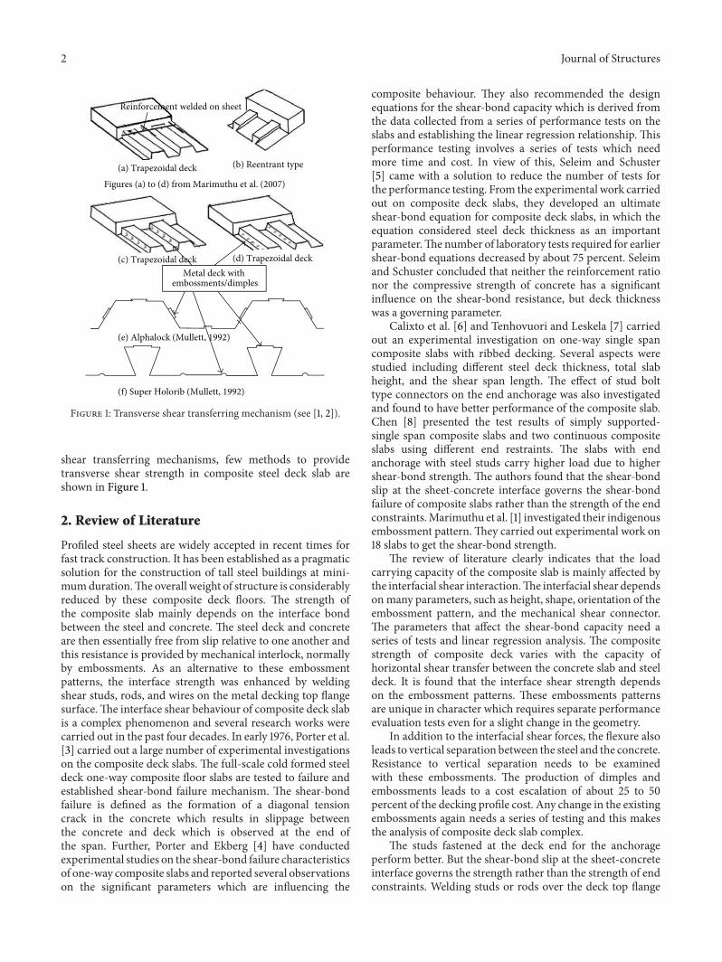
The shear connectors present in the composite deck slabseffectively transfer interfacial shear. The embossment patterntype shear connectors have their own difficulties in termsof uniqueness in character and their cost escalation forproduction. The mechanical shear connectors are simple toimplement with a negligible cost escalation. These mechani-cal shear connectors are fastened withmetal deck by welding,bolting, or screwing into the surface. The welding of studswith deck sheet is categorical due to its tough measures.The present investigation is carried out experimentally withmechanical shear connectors withoutwelding.Onemm thickmild steel sheets are used in this investigation.The plain steelsheets are pressed into trough shape with a size measuring750mm width, 1830mm length, and 75mm depth, and theyare developed as shown in Figure 2.
Themetal deck profile was fabricated with a press breakermachine. It is a high precisionmachine which presses, bends,folds, and accurately forms the deck profile. The holes are
1830 mm
75 mm
50 mm 100 mm
750 mm
Figure 2: Schematic view of metal deck sheet.
produced by punching with relevant equipment fitted withthese press breaker machines. The holes in the deck areformed with aminimum edge distance of 75mmbetween thehole and sheet edge accurately. The centre to centre distancebetween the individual holes in a line along the length of sheetis kept as 300mm. The holes are formed at the appropriatelocations of the deck flange and web. The shear connectorsare positioned through these holes. Three types of shearconnector schemes are derived based on the position of shearconnector assemblies.
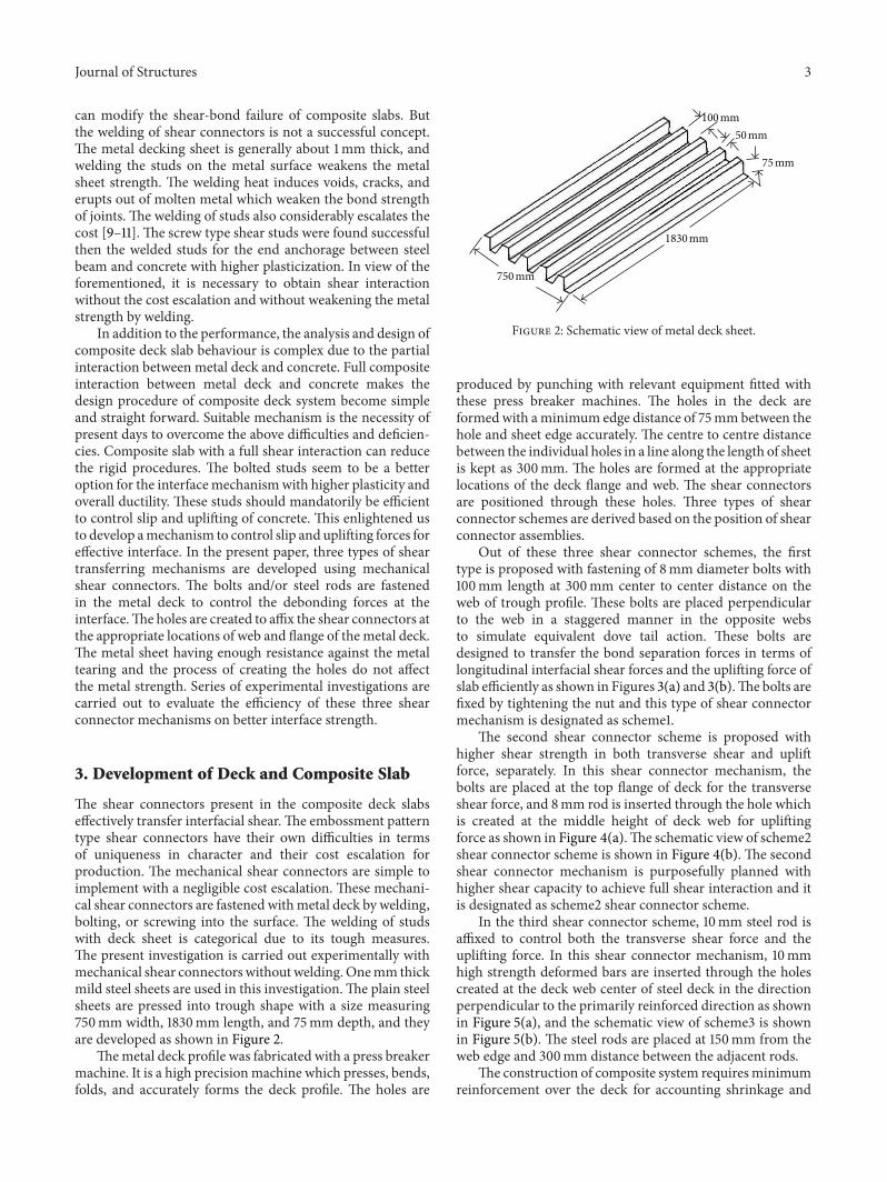
Out of these three shear connector schemes, the firsttype is proposed with fastening of 8mm diameter bolts with100mm length at 300mm center to center distance on theweb of trough profile. These bolts are placed perpendicularto the web in a staggered manner in the opposite websto simulate equivalent dove tail action. These bolts aredesigned to transfer the bond separation forces in terms oflongitudinal interfacial shear forces and the uplifting force ofslab efficiently as shown in Figures 3(a) and 3(b).The bolts arefixed by tightening the nut and this type of shear connectormechanism is designated as scheme1.
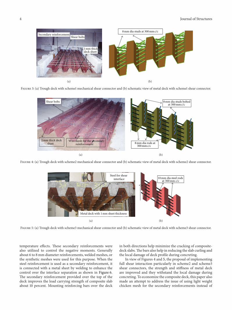
The second shear connector scheme is proposed withhigher shear strength in both transverse shear and upliftforce, separately. In this shear connector mechanism, thebolts are placed at the top flange of deck for the transverseshear force, and 8mm rod is inserted through the hole whichis created at the middle height of deck web for upliftingforce as shown in Figure 4(a).The schematic view of scheme2shear connector scheme is shown in Figure 4(b). The secondshear connector mechanism is purposefully planned withhigher shear capacity to achieve full shear interaction and itis designated as scheme2 shear connector scheme.
In the third shear connector scheme, 10mm steel rod isaffixed to control both the transverse shear force and theuplifting force. In this shear connector mechanism, 10mmhigh strength deformed bars are inserted through the holescreated at the deck web center of steel deck in the directionperpendicular to the primarily reinforced direction as shownin Figure 5(a), and the schematic view of scheme3 is shownin Figure 5(b). The steel rods are placed at 150mm from theweb edge and 300mm distance between the adjacent rods.
The construction of composite system requiresminimumreinforcement over the deck for accounting shrinkage and
4 Journal of Structures
Secondary reinforcementShear bolts
1 mm thick deck sheet
(a)
8 mm dia studs at 300 mm c/c
(b)
Figure 3: (a) Trough deck with scheme1 mechanical shear connector and (b) schematic view of metal deck with scheme1 shear connector.
Shear bolts
Wire mesh for the secondary reinforcement
1 mm thick deck sheet
(a)
8 mm dia studs bolted at 300 mm c/c
300 mm c/c8 mm dia rods at
(b)
Figure 4: (a) Trough deck with scheme2 mechanical shear connector and (b) schematic view of metal deck with scheme2 shear connector.
Steel for shear interface
Metal deck with 1 mm sheet thickness
(a)
at 300 mm c/c 10 mm dia steel rods
(b)
Figure 5: (a) Trough deck with scheme3 mechanical shear connector and (b) schematic view of metal deck with scheme3 shear connector.
temperature effects. These secondary reinforcements werealso utilized to control the negative moments. Generallyabout 6 to 8mm diameter reinforcements, welded meshes, orthe synthetic meshes were used for this purpose. When thesteel reinforcement is used as a secondary reinforcement, itis connected with a metal sheet by welding to enhance thecontrol over the interface separation as shown in Figure 6.The secondary reinforcement provided over the top of thedeck improves the load carrying strength of composite slababout 10 percent. Mounting reinforcing bars over the deck
in both directions help minimize the cracking of composite-deck slabs.The bars also help in reducing the slab curling andthe local damage of deck profile during concreting.
In view of Figures 4 and 5, the proposal of implementingfull shear interaction particularly in scheme2 and scheme3shear connectors, the strength and stiffness of metal deckare improved and they withstand the local damage duringconcreting. To economize the composite deck, this paper alsomade an attempt to address the issue of using light weightchicken mesh for the secondary reinforcements instead of

Journal of Structures 5
Figure 6: Typical view of secondary steel reinforcements [12].
steel reinforcement mat at the top of the composite slab.The use of chicken mesh is very simple to handle andpractise due to its flexible steel wires. The chicken mesh canefficiently control the temperature and shrinkage stresses.Three composite slab specimens are cast for each shearconnector scheme. Out of three composite slab specimens,one slab was examined with 8mm diameter bar and theother two slabs are with chicken mesh for secondary rein-forcements. The selection of 8mm steel reinforcement is anarbitrary choice mainly to evolve the possibilities in strengthreduction due to chicken mesh. The concrete is placed overthe steel deck and the overall depth of 120mm is preciselymaintained in all slab castings. To assess the performanceof composite slabs with mechanical shear connecters, testingof composite slabs without mechanical shear connecter iscarried out. Since the reinforced concrete is engaged in themajor portion of construction industry, the composite deckslab performance is also compared with the test results ofreinforced concrete slabs for better perceptive. The M25concrete ofmix proportion 1 : 1.5 : 3 : 4.8with 28th day averagecompressive strength of 33.25N/mm2 is used for concreting.The trough deck profile was produced from the mild steelsheet of 1mm thickness with modulus elasticity of 2.1 ∗105N/mm2 and Poisson’s ratio of 0.3. The readily available
steel studs and rods are used as shear connectors. Moduluselasticity of steel studs and steel rods is 2.1 ∗ 105N/mm2 andPoisson’s ratio is 0.3.
4. Load Setup and Testing Method
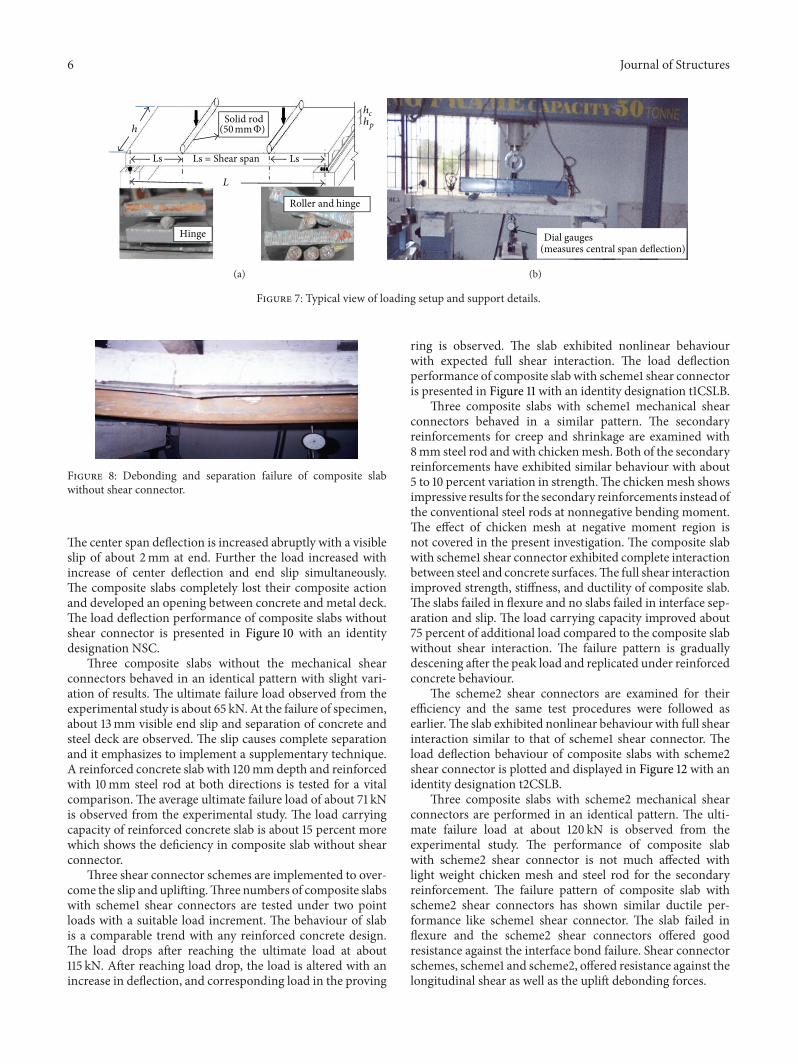
The composite slabs are prepared to be tested under two-point loading condition. The schematic view of the exper-imental setup and the photographs of the hinge and rollersupports are shown in Figure 7. Twomild steel rods of 50mmdiameter are placed over the slab to apply a perfect line load.The rods are placed at a distance of L/4 from the supports.A standard I section ISMB 200 is placed over the rods in thetransverse direction. A 30 ton hydraulic jack is fixed in theloading frame for applying load. The load is measured witha proving ring which is kept between the hydraulic jack andthe ISMB 200 section.The dial gauges are used tomeasure themid span deflection and end slip.Themid span deflection and
the end slip are noted down at specific load intervals.The testseries is started with testing of composite slab without anymechanical shear connector. The two-point load is appliedon slabs and corresponding deflections are observed. Thesteel deck and concrete are separated due to the lack of bondbetween the steel deck and concrete as shown in Figure 8.The load carrying capacity and stiffness are reduced due tothe loss of composite action between concrete and metaldeck. The composite slab without shear interaction carringa maximum average load at about 65 kN is observed from thetest. The metal deck and concrete completely debonded fromeach other and that makes the two parts act separately. Theloss of composite action is evidenced from the metal sheetbuckling at the web top. The results showed the necessityof efficient interface bonding between steel and concreteof composite deck system. The mechanical shear studs androds are necessary to modify the performance of compositesystemby controlling the slip and uplifting forces.Three shearconnector schemes are implemented to control the interfacebehaviour.
The composite slabs with different mechanical shearconnector schemes are tested to failure. The load is increasedand corresponding deflections at three points along the centerline of slab are noted. Until the load reaches ultimum, it isapplied as a load control increment and after that the loadis altered with a displacement control, in which the jackhead movement is controlled with the deflection incrementin the central deflection. During the test, no sudden drop inload is observed up to ultimate load. In the entire testing ofcomposite slab withmechanical shear connectors, no slip wasobserved. Also it is found that the secondary reinforcementin the form of chicken mesh or the 8mm rod is not muchaffecting the performance of composite deck slabs. The com-posite slabs are performed in a ductile manner. The ultimateload carrying capacity of the composite slab with mechanicalshear connector increased considerably and attained about100 to 120 kN. The failure patterns of composite slab withmechanical shear connector are showing in Figure 9. Thecomposite slab initially shown several microcracks and fewcracks is widened after ultimate failure without showing anyslip at the end.
From the experimental investigations, all three types ofmechanical shear connectors performed well and no slip noruplifting between concrete and deck sheet was observed. Thecomposite slabs with shear connectors exhibited full shearinteraction with remarkable increase in the load carryingcapacity.
5. Results and Discussion
Three numbers of composite slabs without any shear con-nectors (NSC) are tested under two-point loads. The loadis increased in steps, and corresponding center span deflec-tions of slabs are measured up to peak. Furthermore afterreaching the peak load, the load is altered for the increaseof deflection and corresponding load is observed. The slabexhibited merely a linear behaviour till the load reachesabout 38 kN and suddenly the load dropped to about 30 kN.
6 Journal of Structures
L
Solid rod
Roller and hinge
Hinge
LsLs Ls = Shear span
(50 mmΦ)hp
h
h
c
(a)
Dial gauges(measures central span deflection)
(b)
Figure 7: Typical view of loading setup and support details.
Figure 8: Debonding and separation failure of composite slabwithout shear connector.
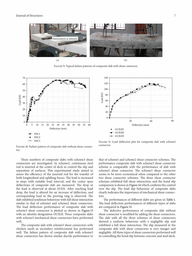
The center span deflection is increased abruptly with a visibleslip of about 2mm at end. Further the load increased withincrease of center deflection and end slip simultaneously.The composite slabs completely lost their composite actionand developed an opening between concrete and metal deck.The load deflection performance of composite slabs withoutshear connector is presented in Figure 10 with an identitydesignation NSC.
Three composite slabs without the mechanical shearconnectors behaved in an identical pattern with slight vari-ation of results. The ultimate failure load observed from theexperimental study is about 65 kN. At the failure of specimen,about 13mm visible end slip and separation of concrete andsteel deck are observed. The slip causes complete separationand it emphasizes to implement a supplementary technique.A reinforced concrete slab with 120mmdepth and reinforcedwith 10mm steel rod at both directions is tested for a vitalcomparison. The average ultimate failure load of about 71 kNis observed from the experimental study. The load carryingcapacity of reinforced concrete slab is about 15 percent morewhich shows the deficiency in composite slab without shearconnector.
Three shear connector schemes are implemented to over-come the slip and uplifting.Three numbers of composite slabswith scheme1 shear connectors are tested under two pointloads with a suitable load increment. The behaviour of slabis a comparable trend with any reinforced concrete design.The load drops after reaching the ultimate load at about115 kN. After reaching load drop, the load is altered with anincrease in deflection, and corresponding load in the proving
ring is observed. The slab exhibited nonlinear behaviourwith expected full shear interaction. The load deflectionperformance of composite slab with scheme1 shear connectoris presented in Figure 11 with an identity designation t1CSLB.
Three composite slabs with scheme1 mechanical shearconnectors behaved in a similar pattern. The secondaryreinforcements for creep and shrinkage are examined with8mm steel rod andwith chickenmesh. Both of the secondaryreinforcements have exhibited similar behaviour with about5 to 10 percent variation in strength.The chickenmesh showsimpressive results for the secondary reinforcements instead ofthe conventional steel rods at nonnegative bending moment.The effect of chicken mesh at negative moment region isnot covered in the present investigation. The composite slabwith scheme1 shear connector exhibited complete interactionbetween steel and concrete surfaces.The full shear interactionimproved strength, stiffness, and ductility of composite slab.The slabs failed in flexure and no slabs failed in interface sep-aration and slip. The load carrying capacity improved about75 percent of additional load compared to the composite slabwithout shear interaction. The failure pattern is graduallydescening after the peak load and replicated under reinforcedconcrete behaviour.
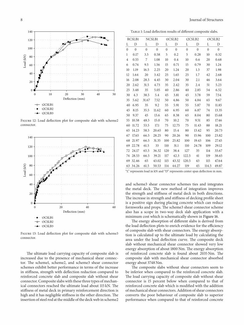
The scheme2 shear connectors are examined for theirefficiency and the same test procedures were followed asearlier.The slab exhibited nonlinear behaviour with full shearinteraction similar to that of scheme1 shear connector. Theload deflection behaviour of composite slabs with scheme2shear connector is plotted and displayed in Figure 12 with anidentity designation t2CSLB.
Three composite slabs with scheme2 mechanical shearconnectors are performed in an identical pattern. The ulti-mate failure load at about 120 kN is observed from theexperimental study. The performance of composite slabwith scheme2 shear connector is not much affected withlight weight chicken mesh and steel rod for the secondaryreinforcement. The failure pattern of composite slab withscheme2 shear connectors has shown similar ductile per-formance like scheme1 shear connector. The slab failed inflexure and the scheme2 shear connectors offered goodresistance against the interface bond failure. Shear connectorschemes, scheme1 and scheme2, offered resistance against thelongitudinal shear as well as the uplift debonding forces.
Journal of Structures 7
Deformation at ultimate
(a) (b)
Figure 9: Typical failure patterns of composite slab with shear connector.
0
10
20
30
40
50
60
70
0 5 10 15 20 25 30 35 40 45 50 55 60Deflection (mm)
Load
(kN
)
NSC1NSC2NSC3
Figure 10: Failure pattern of composite slab without shear connec-tor.
Three numbers of composite slabs with scheme3 shearconnectors are investigated. In scheme3, continuous steelrod is inserted at the center of deck to control the slip andseparation of surfaces. This experimental study aimed toassess the efficiency of the inserted rod for the transfer ofboth longitudinal and uplifting forces. The load is increasedin steps with suitable load interval, and the center spandeflections of composite slab are measured. The drop inthe load is observed at about 115 kN. After reaching loaddrop, the load is altered for an increase of deflection, andcorresponding load in the proving ring is observed. Theslab exhibited nonlinear behaviour with full shear interactionsimilar to that of scheme1 and scheme2 shear connectors.The load deflection performance of composite slab withscheme3 shear connector is plotted as shown in Figure 13with an identity designation t3CSLB. Three composite slabswith scheme3 mechanical shear connectors have performedwell.
The composite slab with scheme3 shear connectors withchicken mesh as secondary reinforcement has performedwell. The failure pattern of composite slab with scheme3shear connectors has shown similar ductile performance to
0
20
40
60
80
100
120
140
20 40 60
Load
(kN
)
Deflection (mm)
t1CSLB1t1CSLB2t1CSLB3
Figure 11: Load deflection plot for composite slab with scheme1connector.
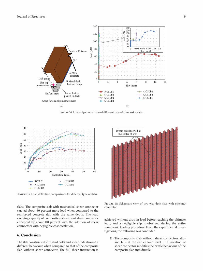
that of scheme1 and scheme2 shear connector schemes. Theperformance composite slab with scheme3 shear connectorscheme is comparable with the performance of slab withscheme2 shear connector. The scheme3 shear connectorseems to be more economical when compared to the othertwo shear connector schemes. The three shear connectorschemes exhibited full shear interaction, and the bond slipcomparison is shown in Figure 14 which confirms the controlover the slip. The load slip behaviour of composite slabsclearly indicates the importance of mechanical shear connec-tors.
The performances of different slabs are given in Table 1.The load deflection performances of different types of slabsare compared in Figure 15.
The defective performance of composite slab withoutshear connector is modified by adding the shear connectors.The slab with all the three schemes of shear connectorsshowed a uniform behaviour with a negligible slip andexhibited a full shear interaction. The slip measured in thecomposite slab with shear connectors is very meager andnegligible. All three types of shear connectors performedwellin controlling the bond slip between concrete and steel deck.
8 Journal of Structures
0 10 20 30 40 500
20
40
60
80
100
120
140
Load
(kN
)
Deflection (mm)
t2CSLB1t2CSLB2t2CSLB3
Figure 12: Load deflection plot for composite slab with scheme2connector.
0 20 40 600
20
40
60
80
100
120
140
Load
(kN
)
Deflection (mm)
t3CSLB1t3CSLB2t3CSLB3
Figure 13: Load deflection plot for composite slab with scheme3connector.
The ultimate load carrying capacity of composite slab isincreased due to the presence of mechanical shear connec-tor. The scheme1, scheme2, and scheme3 shear connectorschemes exhibit better performance in terms of the increasein stiffness, strength with deflection reduction compared toreinforced concrete slab and composite slab without shearconnector. Composite slabswith these three types ofmechan-ical connectors reached the ultimate load about 115 kN. Thestiffness of metal deck in primary reinforcement direction ishigh and it has negligible stiffness in the other direction. Theinsertion of steel rod at themiddle of the deckweb in scheme2
Table 1: Load deflection results of different composite slabs.
RCSLB1 NCSLB1 t1CSLB2 t2CSLB2 t3CSLB2L D L D L D L D L D0 0 0 0 0 0 0 0 0 01 0.17 3.5 0.58 5 0.2 5 0.28 10 0.324 0.55 7 1.08 10 0.4 10 0.6 20 0.686 0.74 9.5 1.56 15 0.71 15 0.79 30 1.2410 1.19 16.5 2.25 20 1.24 20 1.3 37 1.9812 1.64 20 3.42 25 1.65 25 1.7 42 2.6816 2.08 28.5 4.45 30 2.04 30 2.1 46 3.6420 2.62 31.5 4.73 35 2.42 35 2.4 51 5.2325 3.48 35 5.05 40 2.86 40 2.85 54 6.5230 4.3 38.5 5.4 45 3.81 45 3.78 59 7.5435 5.62 31.67 7.52 50 4.86 50 4.84 65 9.6740 6.95 35 9.2 55 5.91 55 5.87 70 11.8545 8.15 35.5 11.62 60 6.95 60 6.87 74 13.3550 9.37 45 13.6 65 8.38 65 8.04 80 15.6855 10.58 48.5 15.0 70 10.2 70 9.51 85 17.4660 11.72 53.5 17.1 75 12.75 75 11.43 88 18.2165 14.23 58.5 20.65 80 15.4 80 13.42 95 20.7367 17.65 66.5 28.25 90 20.26 90 15.96 100 23.8268 21.97 66.5 31.35 100 25.82 100 19.43 106 27.4569 22.78 61.5 33 110 31.1 110 24.78 109 29.1272 24.17 65.5 36.32 120 38.4 127 35 114 33.6774 28.53 66.5 39.21 117 42.3 122.5 41 119 38.6569 32.46 65 43.02 115 43.32 120.5 43 115 47.6463 34.26 61.5 50.53 114 44.27 119 45 114.5 49.87“L” represents load in kN and “D” represents center span deflection in mm.
and scheme3 shear connector schemes ties and integratesthe metal deck. The new method of integration improvesthe strength and stiffness of metal deck in both directions.The increase in strength and stiffness of decking profile sheetis a positive sign during placing concrete which can reduceformworks and props. The scheme3 shear connector schemealso has a scope in two-way deck slab application with aminimum cost which is schematically shown in Figure 16.
The energy absorption of different slabs is derived fromthe load deflection plots to enrich evidence for the efficiencyof composite slab with shear connectors. The energy absorp-tion is calculated up to the ultimate load by calculating thearea under the load deflection curve. The composite deckslab without mechanical shear connector showed very lowenergy absorption of about 1800Nm. The energy absorptionof reinforced concrete slab is found about 2035Nm. Thecomposite slab with mechanical shear connector absorbedenergy about 3748Nm.
The composite slabs without shear connectors seem tobe inferior when compared to the reinforced concrete slab.The load carrying capacity of composite slab without shearconnector is 15 percent below when compared to that ofreinforced concrete slab which is modified with the additionofmechanical shear connectors. Addition of shear connectorsconverts the poor behaviour of composite slab to superiorperformance when compared to that of reinforced concrete
Journal of Structures 9
Dial gauge(for slip
measurement)
Setup for end slip measurement
pasted in deck
Metal deck bottom flange
M25concrete
Half cut view
Depth = 120 mm
Metal L strip
(a)
0 2 4 6 8 10 12 14Slip (mm)
NCSLB1t1CSLB2t2CSLB2t3CSLB2
020406080
100120140
0 0.02 0.04 0.06 0.08 0.1
t1CSLB2t2CSLB2t3CSLB1
Slip (mm)
0
20
40
60
80
100
120
140
Load
(kN
)
Load
(kN
)
(b)
Figure 14: Load-slip comparison of different type of composite slabs.
0 10 20 30 40 50 60
RCSLB1NSCSLB1t1CSLB2
t2CSLB2t3CSLB2
0
20
40
60
80
100
120
140
Load
(kN
)
Deflection (mm)
Figure 15: Load deflection comparisons for different type of slabs.
slabs. The composite slab with mechanical shear connectorcarried about 60 percent more load when compared to thereinforced concrete slab with the same depth. The loadcarrying capacity of composite slab without shear connectorenhanced by about 110 percent with the addition of shearconnectors with negligible cost escalation.
6. Conclusion
The slab constructed with stud bolts and shear rods showed adifferent behaviour when compared to that of the compositeslab without shear connector. The full shear interaction is
10 mm rods inserted at the center of web
Figure 16: Schematic view of two-way deck slab with scheme3connector.
achieved without drop in load before reaching the ultimateload, and a negligible slip is observed during the entiremonotonic loading procedure. From the experimental inves-tigations, the following was conduded.
(1) The composite slab without shear connectors slipsand fails at the earlier load level. The insertion ofshear connector modifies the brittle behaviour of thecomposite slab into ductile.

10 Journal of Structures
(2) Three mechanical shear connector schemes developfull shear interaction and do not show any visibledelamination and slip.
(3) The insertion of steel rods at the middle of thedeck web in scheme2 and scheme3 shear connectorschemes ties and integrates the metal deck. Theintegration improves the strength and stiffness ofmetal deck and reduces formworks and temporarysupports.
(4) Steel rods present in the deck web can be efficientlytied and showcased for the two-way composite decksystem.
(5) The inclusion of shear connector enhances the flexu-ral capacity, stiffness, ductility, and energy absorptionof composite deck system.
(6) The load carrying capacity is improved by about 110percent when compared to that of the compositeslab without mechanical shear connector with min-imum/negligible cost escalation. The composite slabwith mechanical shear connector carried about 60percent additional load when compared to that of thereinforced concrete slab with same depth.
(7) The flexural capacity of composite deck slab withwire mesh is found competitive for shrinkage andtemperature effects.
Acknowledgment
This paper is being published with the kind permission ofDirector of CSIR-SERC, Chennai.
References
[1] V. Marimuthu, S. Seetharaman, S. Arul Jayachandran, A. Chel-lappan, T. K. Bandyopadhyay, and D. Dutta, “Experimentalstudies on composite deck slabs to determine the shear-bondcharacteristic (m-k) values of the embossed profiled sheet,”Journal of Constructional Steel Research, vol. 63, no. 6, pp. 791–803, 2007.
[2] D. L. Mullett, Slim Floor Design and Construction, SCI-P-110,Steel Construction Institute Publication, Berkshire, UK, 1992.
[3] M. L. Porter, C. E. Ekberg Jr., L. F. Greimann, and H. A. Elleby,“Shear bond analysis of steel deck reinforced slabs,” ASCEJournal of the Structural Division, vol. 102, no. 12, pp. 2255–2268,1976.
[4] M. L. Porter and C. E. J. Ekberg, “Design recommendations forsteel deck floor slabs,” ASCE Journal of the Structural Division,vol. 103, no. 11, pp. 2121–2136, 1976.
[5] S. S. Seleim and R. M. Schuster, “Shear-Bond Resistance ofComposite Deck-Slabs,” Canadian Journal of Civil Engineering,vol. 12, no. 2, pp. 316–324, 1985.
[6] J. M. Calixto, A. C. Lavall, C. B. Melo, R. J. Pimenta, and R.C. Monteiro, “Behaviour and strength of composite slabs withribbed decking,” Journal of Constructional Steel Research, vol.46, no. 1–3, pp. 211–212, 1998.
[7] A. I. Tenhovuori and M. V. Leskela, “Longitudinal shearresistance of composite slabs,” Journal of Constructional SteelResearch, vol. 46, no. 1–3, p. 228, 1998.
[8] S. Chen, “Load carrying capacity of composite slabs with var-ious end constraints,” Journal of Constructional Steel Research,vol. 59, no. 3, pp. 385–403, 2003.
[9] W. S. Easterling and C. S. Young, “Strength of composite slabs,”Journal of Structural Engineering, vol. 118, no. 9, pp. 2370–2389,1992.
[10] S. Aslanlar, A. Ogur, U. Ozsarac, E. Ilhan, and Z. Demir, “Effectof welding current on mechanical properties of galvanizedchromided steel sheets in electrical resistance spot welding,”Materials and Design, vol. 28, no. 1, pp. 2–7, 2007.
[11] J. R. UbejdMujagic,W. S. Easterling, and T.M.Murray, “Drilledstandoff screws for shear connection in light composite steel-concrete trusses,” Journal of Constructional Steel Research, vol.63, no. 10, pp. 1404–1414, 2007.
[12] J. W. Rackham, G. H. Couchman, and S. J. Hicks, “Compositeslabs and beams using steel decking: best practice for design andconstruction,” MCRMA Technical Paper 13, SCI Publication,2009.

International Journal of
AerospaceEngineeringHindawi Publishing Corporationhttp://www.hindawi.com Volume 2014
RoboticsJournal of
Hindawi Publishing Corporationhttp://www.hindawi.com Volume 2014
Hindawi Publishing Corporationhttp://www.hindawi.com Volume 2014
Active and Passive Electronic Components
Control Scienceand Engineering
Journal of
Hindawi Publishing Corporationhttp://www.hindawi.com Volume 2014
International Journal of
RotatingMachinery
Hindawi Publishing Corporationhttp://www.hindawi.com Volume 2014
Hindawi Publishing Corporation http://www.hindawi.com
Journal ofEngineeringVolume 2014
Submit your manuscripts athttp://www.hindawi.com
VLSI Design
Hindawi Publishing Corporationhttp://www.hindawi.com Volume 2014
Hindawi Publishing Corporationhttp://www.hindawi.com Volume 2014
Shock and Vibration
Hindawi Publishing Corporationhttp://www.hindawi.com Volume 2014
Civil EngineeringAdvances in
Acoustics and VibrationAdvances in
Hindawi Publishing Corporationhttp://www.hindawi.com Volume 2014
Hindawi Publishing Corporationhttp://www.hindawi.com Volume 2014
Electrical and Computer Engineering
Journal of
Advances inOptoElectronics
Hindawi Publishing Corporation http://www.hindawi.com
Volume 2014
The Scientific World JournalHindawi Publishing Corporation http://www.hindawi.com Volume 2014
SensorsJournal of
Hindawi Publishing Corporationhttp://www.hindawi.com Volume 2014
Modelling & Simulation in EngineeringHindawi Publishing Corporation http://www.hindawi.com Volume 2014
Hindawi Publishing Corporationhttp://www.hindawi.com Volume 2014
Chemical EngineeringInternational Journal of Antennas and
Propagation
International Journal of
Hindawi Publishing Corporationhttp://www.hindawi.com Volume 2014
Hindawi Publishing Corporationhttp://www.hindawi.com Volume 2014
Navigation and Observation
International Journal of
Hindawi Publishing Corporationhttp://www.hindawi.com Volume 2014
DistributedSensor Networks
International Journal of