Embed Size (px)
Citation preview
Hindawi Publishing CorporationMathematical Problems in EngineeringVolume 2013, Article ID 137427, 14 pageshttp://dx.doi.org/10.1155/2013/137427
Research ArticleContact Problem for an Elastic Layer on an Elastic Half PlaneLoaded by Means of Three Rigid Flat Punches
T. S. Ozsahin and O. TaskJner
Civil Engineering Department, Karadeniz Technical University, 61080 Trabzon, Turkey
Correspondence should be addressed to T. S. Ozsahin; [email protected]
Received 21 December 2012; Revised 27 February 2013; Accepted 13 March 2013
Academic Editor: Safa Bozkurt Coskun
Copyright © 2013 T. S. Ozsahin and O. Taskıner.This is an open access article distributed under theCreative CommonsAttributionLicense, which permits unrestricted use, distribution, and reproduction in anymedium, provided the originalwork is properly cited.
The frictionless contact problem for an elastic layer resting on an elastic half plane is considered. The problem is solved by usingthe theory of elasticity and integral transformation technique. The compressive loads P and Q (per unit thickness in 𝑧 direction)are applied to the layer through three rigid flat punches. The elastic layer is also subjected to uniform vertical body force due toeffect of gravity. The contact along the interface between elastic layer and half plane is continuous, if the value of the load factor, 𝜆,is less than a critical value, 𝜆cr. In this case, initial separation loads, 𝜆cr and initial separation points, 𝑥cr are determined. Also therequired distance between the punches to avoid any separation between the punches and the elastic layer is studied and the limitdistance between punches that ends interaction of punches is investigated for various dimensionless quantities. However, if tensiletractions are not allowed on the interface, for 𝜆 > 𝜆cr the layer separates from the interface along a certain finite region. Numericalresults for distance determining the separation area, vertical displacement in the separation zone, contact stress distribution alongthe interface between elastic layer and half plane are given for this discontinuous contact case.
1. Introduction
Contact between deformable bodies abounds in industryand everyday life. Because of the industrial importance ofthe physical processes that take place during contact, aconsiderable effort has beenmade in theirmodeling, analysis,and numerical simulations.
The range of application in contact mechanics startswith problems like foundations in civil engineering, wherethe lift off the foundation from soil due to eccentric forcesacting on a building, railway ballasts, foundation grillages,continuous foundation beams, runaways, liquid tanks restingon the ground, and grain silos is considered. Furthermore,foundation including piles as supporting members or thedriving of piles into the soil is of interest. Also classicalbearing problem of steel constructions and the connectionof structural members by bolts or screws are areas in whichcontact analysis enters the design process in civil engineering[1].
A complete analysis of the interaction problem for elasticbodies generally requires the determination of stresses andstrain within the individual bodies in contact, together with
information regarding the distribution of displacements andstresses at the contact regions.
The contact problem for an elastic layer has attractedconsiderable attention in the past because of its possibleapplication to a variety of structures of practical interest.The layer usually rests on a foundation which may be eitherelastic or rigid and the body force due to gravity may beneglected [2–27] or effect of gravitymay be taken into account[28–35]. Studies regarding the frictionless contact along theinterface may be found in [2–15]. Also contact region mayexhibit frictional characteristics, giving rise to normal andshear traction at the contact surface [16–27].
While initial contact is determined by the geometricfeatures of the bodies, the extent of the contact generallychanges not only by the particular loads applied to the bodiesbut also with the elastic constants of the materials. Due tothe bending of the layer under local compressive loads, inthe absence of gravity effects, the contact area would decreaseto a finite size which is independent of the magnitude ofthe applied load [2–7]. If the effect of gravity was taken intoaccount, the normal stress along the layer subspace interfacewill be compressive and the contact is maintained through
2 Mathematical Problems in Engineering
2
1 I IIII𝑎𝑎𝑏𝑏𝑐𝑐
𝑑𝑑
𝑄𝑄 𝑃
𝑦
𝑥
ℎ
𝑒𝑒
𝜅1, 𝜇1, �1
𝜅2, 𝜇2, �2
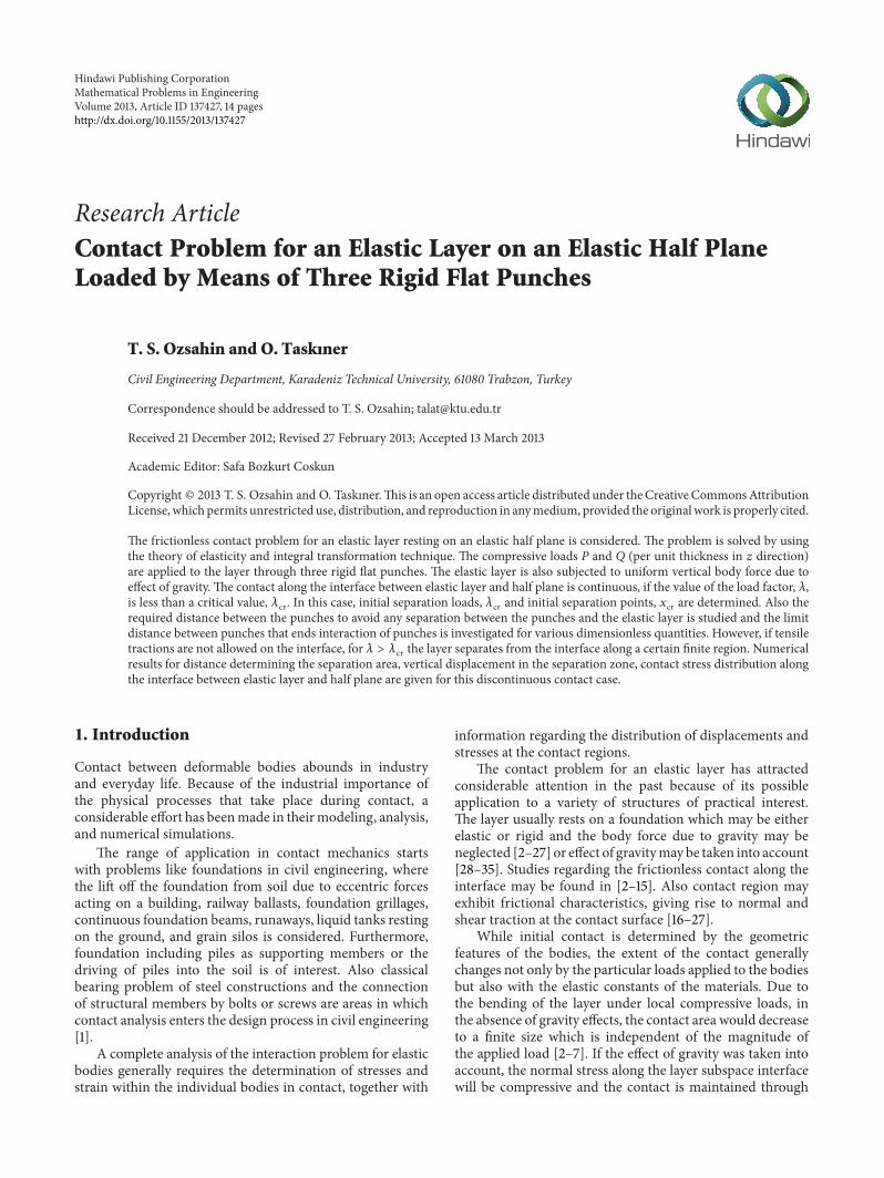
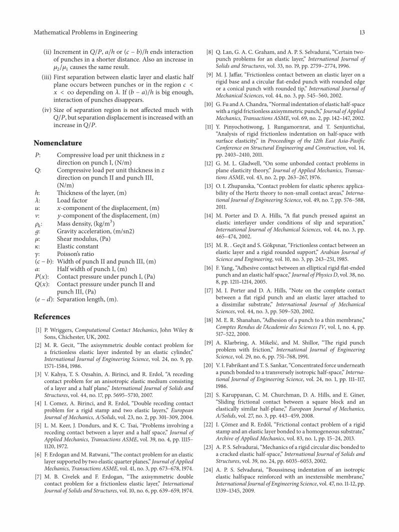
Figure 1: Elastic layer resting on an elastic half plane loaded bymeans of three rigid flat punches.
the frictionless interface unless the compressive applied loadexceeds a certain critical value. When the magnitude of thecompressive external load exceeds a certain value, a separa-tion will take place between the layer and the foundation.Thelength of separation region along the interface is unknown,and the problem becomes a discontinuous contact problem[28–35].
Interaction between an elastic medium and a rigid punchforms another group of contact problems. Rigid punchesmay be structural elements such as foundations, beams, andplates of finite or infinite extent resting on idealized linearlydeformable elastic media. Here, the shape of the contactregion may be known a priori and remains constant, or con-tact region may be changed due to the shape of punch profile[8–27]. The problem of flat-ended rigid punch has importantapplications in soil mechanics, particularly in estimating thesafety of foundations. The application of the three punchesfor an elastic layer resting on an elastic half plane in soilmechanics is obvious; for example, the punches can be takenas foundations placed on layered soil. When the foundationsare placed on soil, there is a possibility of pressure isobarsof adjacent foundations overlapping each other. The soil ishighly stressed in the zones of overlapping, or the differenceof settlement between two adjacent foundations, commonlyreferred to as differential settlement may cause damage tothe structure. It is possible to avoid overlapping of pressuresor differential settlement by installing the foundations atconsiderable distance apart from each other.
In this study, contact problem of the three punches foran elastic layer resting on an elastic half plane is consideredaccording to the theory of elasticity with integral transfor-mation technique. The compressive loads 𝑃 and 𝑄 (per unitthickness in 𝑧 direction) are applied to the layer throughthree rigid flat punches. The width of midmost punch canbe different from the other two punches and thickness of thelayer is constant, ℎ. The layer is subjected to homogeneousvertical body force due to gravity, 𝜌
1𝑔. All surfaces are
frictionless. The layer remains in contact with the elastichalf plane where the magnitude of the load factor 𝜆 is lessthan a critical value, 𝜆cr (𝜆 = 𝑃/𝜌
1𝑔ℎ2). If 𝜆 > 𝜆cr,
the contact is discontinuous and a separation takes placebetween the layer and the half plane. A numerical integration
procedure is performed for the solution of the problems, anddifferent parameters are researched for various dimensionlessquantities for both continuous and discontinuous contactcases. Finally, numerical results are analyzed and conclusionsare drawn.
2. General Expressions for Stresses andDisplacements
Consider a frictionless elastic layer of thickness h lying on anelastic half plane. The geometry and coordinate system areshown in Figure 1. The governing equations are
𝜇𝑘∇2𝑢𝑘+
2𝜇𝑘
(𝜅𝑘− 1)
𝜕
𝜕𝑥
(
𝜕𝑢𝑘
𝜕𝑥
+
𝜕V𝑘
𝜕𝑦
) = 0, (1a)
𝜇𝑘∇2V𝑘+
2𝜇𝑘
(𝜅𝑘− 1)
𝜕
𝜕𝑦
(
𝜕𝑢𝑘
𝜕𝑥
+
𝜕V𝑘
𝜕𝑦
) = 𝜌𝑘𝑔,
(𝑘 = 1, 2)
(1b)
where 𝜌𝑘𝑔 is the intensity of the body force acting vertically in
which 𝜌𝑘and 𝑔 are mass density and gravity acceleration. 𝑢
𝑘
and V𝑘are the𝑥 and𝑦 components of the displacement vector,
𝜇𝑘and 𝜅𝑘represent shear modulus and elastic constant of the
layer and the half plane, respectively. 𝜅𝑘= (3 − 𝛾
𝑘)/(1 + 𝛾
𝑘)
for plane stress and 𝜅𝑘= (3 − 4𝛾
𝑘) for plane strain. 𝛾
𝑘is the
Poisson ratio (𝑘 = 1, 2). Subscript 1 indicates the elastic layerand subscript 2 indicates the elastic half plane.
𝑢𝑝and V
𝑝represent the displacements for the case in
which gravity forces are considered. 𝑢ℎand V
ℎare the
displacements when the gravity forces are ignored, and totalfield of displacements may be expressed as
𝑢 = 𝑢𝑝+ 𝑢ℎ, (2a)
V = V𝑝+ Vℎ. (2b)
Observing that𝑥 = 0 is a plane of symmetry, it is sufficientto consider the problem in the region 0 ≤ 𝑥 ≤ ∞ only. Usingthe symmetry consideration, the following expressions maybe written:
𝑢1(𝑥, 𝑦) = −𝑢
1(−𝑥, 𝑦) , (3a)
V1(𝑥, 𝑦) = V
1(−𝑥, 𝑦) , (3b)
𝑢1(𝑥, 𝑦) =
2
𝜋
∫
∞
0
𝜙1(𝛼, 𝑦) sin (𝛼𝑥) 𝑑𝛼, (3c)
V1(𝑥, 𝑦) =
2
𝜋
∫
∞
0
Ψ1(𝛼, 𝑦) cos (𝛼𝑥) 𝑑𝛼, (3d)
where 𝜙1and Ψ
1functions are inverse Fourier transforms
of 𝑢1and V1respectively. Taking necessary derivatives of (3c)
and (3d), substituting them into (1a) and (1b), and solving the
Mathematical Problems in Engineering 3
second-order differential equations, the following equationsmay be obtained for displacements:
𝑢1ℎ(𝑥, 𝑦) =
2
𝜋
∫
∞
0
[(𝐴 + 𝐵𝑦) 𝑒−𝛼𝑦
+ (𝐶 + 𝐷𝑦) 𝑒𝛼𝑦] sin (𝛼𝑥) 𝑑𝛼,
(4a)
V1ℎ(𝑥, 𝑦) =
2
𝜋
∫
∞
0
[[𝐴 + (
𝜅1
𝛼
𝜅 + 𝑦)𝐵] 𝑒−𝛼𝑦
+ [−𝐶 + (
𝜅1
𝛼
− 𝑦)𝐷] 𝑒𝛼𝑦] cos (𝛼𝑥) 𝑑𝛼.
(4b)
Using Hooke’s law and (4a) and (4b), stress componentswhich do not include the gravity force may be expressed asfollows:
𝜎𝑥1ℎ
(𝑥, 𝑦) =
4𝜇1
𝜋
∫
∞
0
[[𝛼 (𝐴 + 𝐵𝑦) − (
3 − 𝜅1
2
)𝐵] 𝑒−𝛼𝑦
+ [𝛼 (𝐶 + 𝐷𝑦) + (
3 − 𝜅𝑖
2
)𝐷] 𝑒𝛼𝑦]
× cos (𝛼𝑥) 𝑑𝛼,(5a)
𝜎𝑦1ℎ
(𝑥, 𝑦) =
4𝜇1
𝜋
∫
∞
0
[− [𝛼 (𝐴 + 𝐵𝑦) + (
𝜅1+ 1
2
)𝐵] 𝑒−𝛼𝑦
+[−𝛼 (𝐶 + 𝐷𝑦) +(
𝜅1+ 1
2
)𝐷] 𝑒𝛼𝑦]
× cos (𝛼𝑥) 𝑑𝛼,(5b)
𝜏𝑥𝑦1ℎ
(𝑥, 𝑦) =
4𝜇1
𝜋
∫
∞
0
[− [𝛼 (𝐴 + 𝐵𝑦) + (
𝜅𝑖− 1
2
)𝐵] 𝑒−𝛼𝑦
+ [𝛼 (𝐶 + 𝐷𝑦) − (
𝜅𝑖− 1
2
)𝐷] 𝑒𝛼𝑦]
× sin (𝛼𝑥) 𝑑𝛼.(5c)
For the case in which gravity force exist, particular partof the displacement components corresponding to 𝜌
1𝑔, the
following expressions are obtained, that is, special solution ofthe Navier equations for a layer with a height ℎ:
𝑢1𝑝=
3 − 𝜅1
8𝜇1
𝜌1𝑔ℎ
2
𝑥, (6a)
V1𝑝=
𝜌1𝑔𝑦
2𝜇1
[
(𝜅1− 1)
(𝜅1+ 1)
(𝑦 − ℎ) −
(𝜅1+ 1)
8
ℎ] , (6b)
𝜎𝑦1𝑝
= 𝜌1𝑔 (𝑦 − ℎ) , (6c)
𝜎𝑥1𝑝
= 𝜌1𝑔(𝑦 −
ℎ
2
)
(1 + 𝜅2)
(1 + 𝜅2) + 2𝜇
2(1 + 𝜅
1)
, (6d)
𝜏𝑥𝑦1𝑝
= 0. (6e)
Considering the orthogonal axes shown in Figure 1,displacements will be zero for 𝑦 = −∞, and if 𝜇
2, ]2are the
elastic constants of the half plane, then the homogenous fieldof displacements and stresses of the elastic half plane may beobtained as
𝑢2ℎ(𝑥, 𝑦) =
2
𝜋
∫
∞
0
[(𝐸 + 𝐹𝑦) 𝑒𝛼𝑦] sin (𝛼𝑥) 𝑑𝛼, (7a)
V2ℎ(𝑥, 𝑦) =
2
𝜋
∫
∞
0
[[−𝐸 + (
𝜅2
𝛼
− 𝑦)𝐹] 𝑒𝛼𝑦] cos (𝛼𝑥) 𝑑𝛼,
(7b)
𝜎𝑥2ℎ
(𝑥, 𝑦) =
4𝜇2
𝜋
∫
∞
0
[[𝛼 (𝐸 + 𝐹𝑦) + (
3 − 𝜅2
2
)𝐹] 𝑒𝛼𝑦]
× cos (𝛼𝑥) 𝑑𝛼,(7c)
𝜎𝑦2ℎ
(𝑥, 𝑦) =
4𝜇2
𝜋
∫
∞
0
[[ − 𝛼 (𝐸 + 𝐹𝑦)
+ (
𝜅2+ 1
2
)𝐹] 𝑒𝛼𝑦] cos (𝛼𝑥) 𝑑𝛼,
(7d)
𝜏𝑥𝑦2ℎ
(𝑥, 𝑦) =
4𝜇2
𝜋
∫
∞
0
[[𝛼 (𝐸 + 𝐹𝑦) − (
𝜅2− 1
2
)𝐹] 𝑒𝛼𝑦]
× sin (𝛼𝑥) 𝑑𝛼,(7e)
subscript 2 indicates the elastic half plane. Note that the bodyforce acting in the foundation is neglected since it does notdisturb the contact pressure distribution. A, B, C, D, E, and Fare the unknown constants, which will be determined fromthe boundary and continuity conditions at 𝑦 = 0 and 𝑦 = ℎ.
3. Case of Continuous Contact
An elastic layer with a height of ℎ resting on an elastic halfplane, shown in Figure 1, is analyzed for unit thickness in𝑧 direction. Widths of punches at both sides are similar,(𝑐−𝑏)/ℎ, and each of these punches transmits a concentratedload of 𝑄 to the elastic layer. The width of the midmostpunch is different, 2𝑎/ℎ and it is subjected to a concen-trated load, 𝑃. All surfaces are frictionless. Particularly, theinitial separation load (𝜆cr) and point (𝑥cr) where the layerseparated from the elastic half plane and the variation ofthe stress distribution between elastic layer and elastic halfplane is examined depending on material properties, widthof punches, and magnitude of the external loads, 𝑃 and 𝑄.Due to the different settlement of punches, a separation takesplace between punch I and elastic layer, if punches are closeenough. Therefore, the critical distance between the punchesindicating the initiation of separation between the punch Iand the elastic layer is researched and also limit distancebetween the punches where the interaction of punches endsis investigated.
If load factor (𝜆) is sufficiently small, then the contactalong the layer-subspace, 𝑦 = 0, 0 < 𝑥 < ∞, will be
4 Mathematical Problems in Engineering
continuous, andA, B, C, D, E, and Fmust be determined fromthe following boundary and continuity conditions:
𝜎𝑦1(𝑥, ℎ) =
{{
{{
{
−𝑃 (𝑥) , 0 < 𝑥 < 𝑎
−𝑄 (𝑥) , 𝑏 < 𝑥 < 𝑐
0, 𝑎 < 𝑥 < 𝑏, 𝑐 < 𝑥 < ∞,
(8a)
𝜏𝑥𝑦1(𝑥, ℎ) = 0, 0 < 𝑥 < ∞, (8b)
𝜏𝑥𝑦1(𝑥, 0) = 0, 0 < 𝑥 < ∞, (8c)
𝜏𝑥𝑦2(𝑥, 0) = 0, 0 < 𝑥 < ∞, (8d)
𝜎𝑦1(𝑥, 0) = 𝜎
𝑦2(𝑥, 0) , 0 < 𝑥 < ∞, (8e)
𝜕
𝜕𝑥
[V2(𝑥, 0) − V
1(𝑥, 0)] = 0, 0 < 𝑥 < ∞, (8f)
𝜕
𝜕𝑥
[V1(𝑥, ℎ)] = 0, 0 < 𝑥 < 𝑎, (8g)
𝜕
𝜕𝑥
[V1(𝑥, ℎ)] = 0, 𝑏 < 𝑥 < 𝑐, (8h)
in which subscripts 1 and 2 indicate relation to the elasticlayer and the elastic half plane, respectively. 𝑃(𝑥) is theunknown contact pressure under punch I and 𝑄(𝑥) is theunknown contact pressure under punch II, which have notbeen determined yet. If a separation occurs between theelastic layer and elastic half plane, this will give rise to adiscontinuous contact position and the following results forformer solution will no longer be valid and new solution willbe attained for the latter case.
Equilibrium conditions of the problem may be expressedas
∫
𝑎
0
𝑃 (𝑥) 𝑑𝑥 =
𝑃
2
, (9a)
∫
𝑐
𝑏
𝑄 (𝑥) 𝑑𝑥 = 𝑄. (9b)
Displacement and stress expressions (4a), (4b), (5a)–(5c), (6a)–(6e), and (7a)–(7e) are substituted into boundaryconditions (8a)–(8f), and unknown constants A, B, C, D, E,and F are determined in terms of unknown functions 𝑃(𝑥)and 𝑄(𝑥). By making use of (8g) and (8h), after some simplemanipulations, onemay obtain the following singular integralequations for 𝑃(𝑥) and 𝑄(𝑥) [36, 37]:
−
1
𝜋𝜇1
∫
𝑎
0
[𝑘1(𝑥, 𝑡) +
(1 + 𝜅1)
4
(
1
𝑡 + 𝑥
+
1
𝑡 − 𝑥
)]𝑃 (𝑡) 𝑑𝑡
−
1
𝜋𝜇1
∫
𝑐
𝑏
[𝑘1(𝑥, 𝑡) +
(1 + 𝜅1)
4
(
1
𝑡 + 𝑥
+
1
𝑡 − 𝑥
)]
× 𝑄 (𝑡) 𝑑𝑡 = 0, 0 < 𝑥 < 𝑎,
(10a)
−
1
𝜋𝜇1
∫
𝑎
0
[𝑘1(𝑥, 𝑡) +
(1 + 𝜅1)
4
(
1
𝑡 + 𝑥
+
1
𝑡 − 𝑥
)]𝑃 (𝑡) 𝑑𝑡
−
1
𝜋𝜇1
∫
𝑐
𝑏
[𝑘1(𝑥, 𝑡) +
(1 + 𝜅1)
4
(
1
𝑡 + 𝑥
+
1
𝑡 − 𝑥
)]
× 𝑄 (𝑡) 𝑑𝑡 = 0, 𝑏 < 𝑥 < 𝑐,
(10b)
where
𝑘1(𝑥, 𝑡) = ∫
∞
0
{{
𝛼3
8 (1 + 𝜅1)
× [[(1 + 𝜅2) +
𝜇2
𝜇1(1 + 𝜅
1)
]
+ 𝑒−2𝛼ℎ
[4𝛼ℎ (1 + 𝜅2) −
2𝜇2
𝜇1(1 + 𝜅
1)
]
+ 𝑒−4𝛼ℎ
[−1 − 𝜅2+
𝜇2
𝜇1(1 + 𝜅
1)
]]}(Δ)−1
−
(1 + 𝜅1)
4
}
× {sin𝛼 (𝑡 + 𝑥) − sin𝛼 (𝑡 − 𝑥)}𝑑𝛼,(11)
in which
Δ = 𝛼3(2{(−1 − 𝜅
2−
𝜇2
𝜇1(1 + 𝜅
1)
)
+ 𝑒−4𝛼ℎ
[−1 − 𝜅2+
𝜇2
𝜇1(1 + 𝜅
1)
]
+ 𝑒−2𝛼ℎ
[ (1 + 𝜅2) (2 + 4𝛼
2ℎ2)
+
4𝛼ℎ𝜇2
𝜇1(−1 − 𝜅
1)
]})
−1
.
(12)
If evaluated values of A, B, C, and D in terms of 𝑃(𝑥) and𝑄(𝑥) are substituted into (5b), the expression of the contactstress between elastic layer and half plane may be obtained as
𝜎𝑦1(𝑥, 0) =− 𝜌
1𝑔ℎ −
1
𝜋
∫
𝑎
0
𝑘2(𝑥, 𝑡) 𝑃 (𝑡) 𝑑𝑡
−
1
𝜋
∫
𝑐
𝑏
𝑘2(𝑥, 𝑡) 𝑄 (𝑡) 𝑑𝑡, 0 < 𝑥 < ∞,
(13)
Mathematical Problems in Engineering 5
in which 𝜌1and 𝑔 are mass density and gravity acceleration,
respectively, where
𝑘2(𝑥, 𝑡) = ∫
∞
0
{
𝛼3𝜇2
𝜇1(1 + 𝜅
1)
× [𝑒−3𝛼ℎ
(−1 + 𝛼ℎ) + 𝑒−𝛼ℎ
(1 + 𝛼ℎ)] } (Δ)−1
× {cos𝛼 (𝑡 + 𝑥) + cos𝛼 (𝑡 − 𝑥)}𝑑𝛼.(14)
To simplify the numerical analysis, the following dimen-sionless quantities are introduced:
𝑥1= 𝑎𝑟1, (15a)
𝑡1= 𝑎𝑠1, (15b)
𝑥2=
𝑐 − 𝑏
2
𝑟2+
𝑐 + 𝑏
2
, (15c)
𝑡2=
𝑐 − 𝑏
2
𝑠2+
𝑐 + 𝑏
2
, (15d)
𝑔1(𝑠1) =
𝑃 (𝑎𝑠1)
𝑃/ℎ
, (15e)
𝑔2(𝑠2) =
𝑄 (((𝑐 − 𝑏) /2) 𝑠2+ (𝑐 + 𝑏) /2)
𝑃/ℎ
, (15f)
𝛼 = 𝑤ℎ, (15g)
𝜆 =
𝑃
𝜌1𝑔ℎ2. (15h)
Substituting from (15a)–(15h), (9a), (9b) and (10a), (10b) maybe expressed as
∫
1
0
𝑔1(𝑠1)
𝑎
ℎ
𝑑𝑠1=
1
2
, (16a)
∫
1
−1
𝑔2(𝑠2)
𝑐 − 𝑏
2ℎ
𝑑𝑠2=
𝑄
𝑃
, (16b)
−
1
𝜋
∫
1
0
𝑔1(𝑠1)
𝑎
ℎ
𝑑𝑠1[𝑚1(𝑟1, 𝑠1) +
(1 + 𝜅1)
4
× (
1
𝑎 (𝑠1+ 𝑟1)
−
1
𝑎 (𝑠1− 𝑟1)
)]
−
1
𝜋
∫
1
−1
𝑔2(𝑠2)
𝑐 − 𝑏
2ℎ
𝑑𝑠2
× [𝑚2(𝑟1, 𝑠2) +
(1 + 𝜅1)
4
× (
1
(((𝑐 − 𝑏) /2) 𝑠2+ (𝑐 + 𝑏) /2) + 𝑎𝑟
1
−
1
(((𝑐 − 𝑏) /2) 𝑠2+(𝑐 + 𝑏) /2) − 𝑎𝑟
1
)]= 0,
0 < 𝑟1< 1,
(16c)
−
1
𝜋
∫
1
0
𝑔1(𝑠1)
𝑎
ℎ
𝑑𝑠1
× [𝑚3(𝑟2, 𝑠1) +
(1 + 𝜅1)
4
× (
1
𝑎𝑠1+ (((𝑐 − 𝑏) /2) 𝑟
2+ (𝑐 + 𝑏) /2)
−
1
𝑎𝑠1− (((𝑐 − 𝑏) /2) 𝑟
2+ (𝑐 + 𝑏) /2)
)]
−
1
𝜋
∫
1
−1
𝑔2(𝑠2)
𝑐 − 𝑏
2
𝑑𝑠2
× [𝑚4(𝑟2, 𝑠2) +
(1 + 𝜅1)
4
× (
1
((𝑐 − 𝑏) /2) (𝑠2+ 𝑟2) + (𝑐 + 𝑏)
−
1
((𝑐 − 𝑏) /2) (𝑠2− 𝑟2)
)] = 0,
− 1 < 𝑟2< 1,
(16d)
𝜎𝑦1(𝑥, 0)
𝑃/ℎ
= −
1
𝜆
−
1
𝜋
∫
1
0
𝑚5(𝑟1, 𝑠1) 𝑔1(𝑠1)
𝑎
ℎ
𝑑𝑠1
−
1
𝜋
∫
1
−1
𝑚6(𝑟2, 𝑠2) 𝑔2(𝑠2)
𝑐 − 𝑏
2ℎ
𝑑𝑠2,
(16e)
where
𝑚1(𝑟1, 𝑠1) = 𝑘1(𝑥1, 𝑡1) , (17a)
𝑚2(𝑟1, 𝑠2) = 𝑘1(𝑥1, 𝑡2) , (17b)
𝑚3(𝑟2, 𝑠1) = 𝑘1(𝑥2, 𝑡1) , (17c)
𝑚4(𝑟2, 𝑠2) = 𝑘1(𝑥2, 𝑡2) , (17d)
𝑚5(𝑟1, 𝑠1) = 𝑘2(𝑥1, 𝑡1) , (17e)
𝑚6(𝑟2, 𝑠2) = 𝑘2(𝑥2, 𝑡2) . (17f)
The index of the integral equations in (16a)–(16e) is +1;so the functions 𝑔
1(𝑠1) and 𝑔
2(𝑠2) may be expressed in the
following forms:
𝑔1(𝑠1) = 𝐺1(𝑠1) (1 − 𝑠
2
1)
−1/2
, (0 < 𝑠1< 1) , (18a)
𝑔2(𝑠2) = 𝐺2(𝑠2) (1 − 𝑠
2
2)
−1/2
, (−1 < 𝑠2< 1) , (18b)
where 𝐺1(𝑠1) is bounded in [0, 1] and 𝐺
2(𝑠2) is bounded in
[−1, 1].Then using appropriate Gauss-Chebyshev integrationformula given in [36], (16a)–(16d) are replaced by the follow-ing algebraic equations:
𝑛
∑
𝑖=1
𝜋𝑊𝑖
𝑎
ℎ
𝐺1(𝑠1𝑖) =
1
2
, (19a)
6 Mathematical Problems in Engineering
𝑛
∑
𝑖=1
𝜋𝑊𝑖
𝑐 − 𝑏
2ℎ
𝐺2(𝑠2𝑖) =
𝑄
𝑃
, (19b)
−
𝑛
∑
𝑖=1
𝑊𝑖𝐺1(𝑠1𝑖)
𝑎
ℎ
[
[
𝑚1(𝑟1𝑗, 𝑠1𝑖) +
(1 + 𝜅1)
4
× (
1
𝑎 (𝑠1𝑖+ 𝑟1𝑗)
−
1
𝑎 (𝑠1𝑖− 𝑟1𝑗)
)]
]
−
𝑛
∑
𝑖=1
𝑊𝑖𝐺2(𝑠2𝑖)
𝑐 − 𝑏
2ℎ
× [
[
𝑚2(𝑟1𝑗, 𝑠2𝑖) +
(1 + 𝜅1)
4
× (
1
(((𝑐 − 𝑏) /2) 𝑠2𝑖+ (𝑐 + 𝑏) /2) + 𝑎𝑟
1𝑗
−
1
(((𝑐 − 𝑏) /2) 𝑠2𝑖+(𝑐 + 𝑏) /2) − 𝑎𝑟
1𝑗
)]
]
= 0,
(𝑗 = 1, . . . , 𝑛 − 1) ,
(19c)
−
𝑛
∑
𝑖=1
𝑊𝑖𝐺1(𝑠1𝑖)
𝑎
ℎ
× [
[
𝑚3(𝑟2𝑗, 𝑠1𝑖) +
(1 + 𝜅1)
4
× (
1
𝑎𝑠1𝑖+ (((𝑐 − 𝑏) /2) 𝑟
2𝑗+ (𝑐 + 𝑏) /2)
−
1
𝑎𝑠1𝑖− (((𝑐 − 𝑏) /2) 𝑟
2𝑗+ (𝑐 + 𝑏) /2)
)]
]
−
𝑛
∑
𝑖=1
𝑊𝑖𝐺2(𝑠2𝑖)
𝑐 − 𝑏
2ℎ
× [
[
𝑚4(𝑟2𝑗, 𝑠2𝑖) +
(1 + 𝜅1)
4
× (
1
((𝑐 − 𝑏) /2) (𝑠2𝑖+ 𝑟2𝑗) + (𝑐 + 𝑏)
−
1
((𝑐 − 𝑏) /2) (𝑠2𝑖− 𝑟2𝑗)
)]
]
= 0,
(𝑗 = 1, . . . , 𝑛 − 1) ,
(19d)
𝑊1= 𝑊𝑛=
1
2𝑛 − 2
, 𝑊𝑖=
1
𝑛 − 1
,
(𝑖 = 2, . . . , 𝑛 − 1) ,
(19e)
𝑠1𝑖= cos( 𝑖 − 1
2𝑛 − 1
𝜋) , 𝑠2𝑖= cos( 𝑖 − 1
𝑛 − 1
𝜋) ,
(𝑖 = 1, . . . , 𝑛) ,
(19f)
𝑟1𝑗= cos(
2𝑗 − 1
4𝑛 − 2
𝜋) , 𝑟2𝑗= cos(
2𝑗 − 1
2𝑛 − 2
𝜋) ,
(𝑗 = 1, . . . , 𝑛 − 1) .
(19g)
The unknowns𝐺1(𝑠1𝑖) and𝐺
2(𝑠2𝑖) (𝑖 = 1, . . . , 𝑛) are deter-
mined from the system (19a)–(19d). By using (18a), (18b), sub-stituting the results into (16e), and using Gauss-Chebyshevintegration formula, the contact stress 𝜎
𝑦1(𝑥, 0)ℎ/𝑃 is evalu-
ated. It should be observed that the integral equations (16c)and (16d) are valid provided the contact stress 𝜎
𝑦1(𝑥, 0)ℎ/𝑃
is compressive everywhere; that is, 0 < 𝑥 < ∞. The criticalload factor, 𝜆cr and the corresponding location of interfaceseparation, 𝑥cr can be determined through the use of thefollowing condition for various dimensionless quantities:
𝜎𝑦1(𝑥, 0)
𝑃/ℎ
= 0. (20)
4. Case of Discontinuous Contact
Since the interface cannot carry tensile tractions for 𝜆 > 𝜆cr,there will be separation between the elastic layer and theelastic half plane in the neighborhood of 𝑥 = 𝑥cr on thecontact plane 𝑦 = 0, as shown in Figure 1. Assuming thatthe separation region is described by 𝑑 < 𝑥 < 𝑒, 𝑦 = 0,where 𝑑 and 𝑒 are unknowns and functions of 𝜆, boundaryand continuity conditions for the discontinuous contact caseare defined as follows:
𝜎𝑦1(𝑥, ℎ) =
{{
{{
{
−𝑃 (𝑥) , 0 < 𝑥 < 𝑎
−𝑄 (𝑥) , 𝑏 < 𝑥 < 𝑐
0, 𝑎 < 𝑥 < 𝑏, 𝑐 < 𝑥 < ∞,
(21a)
𝜏𝑥𝑦1(𝑥, ℎ) = 0, 0 < 𝑥 < ∞, (21b)
𝜏𝑥𝑦1(𝑥, 0) = 0, 0 < 𝑥 < ∞, (21c)
𝜏𝑥𝑦2(𝑥, 0) = 0, 0 < 𝑥 < ∞, (21d)
𝜎𝑦1(𝑥, 0) = 𝜎
𝑦2(𝑥, 0) , 0 < 𝑥 < ∞, (21e)
𝜕
𝜕𝑥
[V2(𝑥, 0) − V
1(𝑥, 0)] = {
𝜑 (𝑥) , 𝑑 < 𝑥 < 𝑒
0, 0 < 𝑥 < 𝑑, 𝑒 < 𝑥 < ∞,
(21f)
𝜎𝑦1(𝑥, 0) = 𝜎
𝑦2(𝑥, 0) = 0, 𝑑 < 𝑥 < 𝑒, (21g)
Mathematical Problems in Engineering 7
𝜕
𝜕𝑥
[V1(𝑥, ℎ)] = 0, 0 < 𝑥 < 𝑎, (21h)
𝜕
𝜕𝑥
[V1(𝑥, ℎ)] = 0, 𝑐 < 𝑥 < 𝑏. (21i)
After utilizing the boundary and continuity conditionsdefined in (21a)–(21f), new values for the constantsA, B, C, D,E, and F which appear in (4a), (4b), (5a)–(5c), and (7a)–(7e)may be obtained in terms of new unknown functions 𝑃(𝑥),𝑄(𝑥), and 𝜑(𝑥). Unknown functions are then determinedfrom the conditions (21h)-(21i) which have not yet beensatisfied. These conditions give the following system ofsingular integral equations:
−
1
𝜋𝜇1
∫
𝑎
0
[𝑘1(𝑥, 𝑡) +
(1 + 𝜅1)
4
(
1
𝑡 + 𝑥
−
1
𝑡 − 𝑥
)]𝑃 (𝑡) 𝑑𝑡
−
1
𝜋𝜇1
∫
𝑐
𝑏
[𝑘1(𝑥, 𝑡) +
(1 + 𝜅1)
4
(
1
𝑡 + 𝑥
−
1
𝑡 − 𝑥
)]𝑄 (𝑡) 𝑑𝑡
+
1
𝜋
∫
𝑒
𝑑
𝑘2(𝑥, 𝑡) 𝜑 (𝑡) 𝑑𝑡 = 0, 0 < 𝑥 < 𝑎,
(22a)
−
1
𝜋𝜇1
∫
𝑎
0
[𝑘1(𝑥, 𝑡) +
(1 + 𝜅1)
4
(
1
𝑡 + 𝑥
−
1
𝑡 − 𝑥
)]𝑃 (𝑡) 𝑑𝑡
−
1
𝜋𝜇1
∫
𝑐
𝑏
[𝑘1(𝑥, 𝑡) +
(1 + 𝜅1)
4
(
1
𝑡 + 𝑥
−
1
𝑡 − 𝑥
)]𝑄 (𝑡) 𝑑𝑡
+
1
𝜋
∫
𝑒
𝑑
𝑘2(𝑥, 𝑡) 𝜑 (𝑡) 𝑑𝑡 = 0, 𝑏 < 𝑥 < 𝑐,
(22b)
1
𝜋
∫
𝑎
0
𝑘2(𝑥, 𝑡) 𝑃 (𝑡) 𝑑𝑡 +
1
𝜋
∫
𝑐
𝑏
𝑘2(𝑥, 𝑡) 𝑄 (𝑡) 𝑑𝑡
−
𝜇1
𝜋
∫
𝑒
𝑑
[𝑘3(𝑥, 𝑡) −
4𝜇2/𝜇1
(1 + 𝜅2) + 𝜇2/𝜇1(1 + 𝜅
1)
× (
1
𝑡 + 𝑥
+
1
𝑡 − 𝑥
)]𝜑 (𝑡) 𝑑𝑡 − 𝜌1𝑔ℎ = 0,
𝑑 < 𝑥 < 𝑒,
(22c)
where kernels 𝑘1(𝑥, 𝑡) and 𝑘
2(𝑥, 𝑡) are given by (11) and (14)
and
𝑘3(𝑥, 𝑡) = ∫
∞
0
{{−
2𝛼3𝜇2
𝜇1
{𝑒−2𝛼ℎ
(2 + 4𝛼2ℎ2) − 𝑒−4𝛼ℎ
− 1}}
× (Δ)−1+
4𝜇2/𝜇1
(1 + 𝜅2) + 𝜇2/𝜇1(1 + 𝜅
1)
}
× {sin𝛼 (𝑡 + 𝑥) + sin𝛼 (𝑡 − 𝑥)} 𝑑𝛼,(23)
in which Δ is given by (12).The index of integral equations (22a) and (22b) is +1. On
the other hand, the index of the singular integral equation(22c) is −1 due to the physical requirement of smooth contact
at the end points 𝑑 and 𝑒 [37]. Thus, in solving the problemthe two conditions which would account for the unknowns 𝑑and 𝑒 are the consistency condition of integral equation (22c)and the single-valuedness condition
∫
𝑒
𝑑
𝜑 (𝑥) 𝑑𝑥 = 0. (24)
Defining the following dimensionless quantities
𝑥3=
𝑒 − 𝑑
2
𝑟3+
𝑒 + 𝑑
2
, 𝑡3=
𝑒 − 𝑑
2
𝑠3+
𝑒 + 𝑑
2
, (25a)
𝑔3(𝑠3) =
𝜇1𝜑 (((𝑒 − 𝑑) /2) 𝑠
3+ (𝑒 + 𝑑) /2)
𝑃/ℎ
; (25b)
by making use of (15a)–(15h), the integral equations (22a)–(22c) may be expressed as follows:
−
1
𝜋
∫
1
0
𝑔1(𝑠1)
𝑎
ℎ
𝑑𝑠1[𝑚∗
1(𝑟1, 𝑠1) +
(1 + 𝜅1)
4
× (
1
𝑎 (𝑠1+ 𝑟1)
−
1
𝑎 (𝑠1− 𝑟1)
)]
−
1
𝜋
∫
1
−1
𝑔2(𝑠2)
𝑐 − 𝑏
2ℎ
𝑑𝑠2
× [𝑚∗
2(𝑟1, 𝑠2) +
(1 + 𝜅1)
4
× (
1
(((𝑐 − 𝑏) /2) 𝑠2+ (𝑐 + 𝑏) /2) + 𝑎𝑟
1
−
1
(((𝑐 − 𝑏) /2) 𝑠2+ (𝑐 + 𝑏) /2) − 𝑎𝑟
1
)]
+
1
𝜋
∫
1
−1
𝑔3(𝑠3)𝑚∗
3(𝑟1, 𝑠3)
𝑒 − 𝑑
2ℎ
𝑑𝑠3= 0,
0 < 𝑟1< 1,
(26a)
−
1
𝜋
∫
1
−1
𝑔1(𝑠1)
𝑎
ℎ
𝑑𝑠1
× [𝑚∗
4(𝑟2, 𝑠1) +
(1 + 𝜅1)
4
× (
1
𝑎𝑠1+ (((𝑐 − 𝑏) /2) 𝑟
2+ (𝑐 + 𝑏) /2)
−
1
𝑎𝑠1− (((𝑐 − 𝑏) /2) 𝑟
2+ (𝑐 + 𝑏) /2)
)]
−
1
𝜋
∫
1
−1
𝑔2(𝑠2)
𝑐 − 𝑏
2ℎ
𝑑𝑠2[𝑚∗
5(𝑟2, 𝑠2) +
(1 + 𝜅1)
4
× (
1
((𝑐−𝑏) /2) (𝑠2+𝑟2)+(𝑐+𝑏)
−
1
((𝑐 − 𝑏) /2) (𝑠2− 𝑟2)
)]
+
1
𝜋
∫
1
−1
𝑔3(𝑠3)𝑚∗
6(𝑟2, 𝑠3)
𝑒 − 𝑑
2ℎ
𝑑𝑠3= 0,
− 1 < 𝑟2< 1,
(26b)
8 Mathematical Problems in Engineering
−
1
𝜋
∫
1
−1
𝑔1(𝑠1)𝑚∗
7(𝑟3, 𝑠1)
𝑎
ℎ
𝑑𝑠1
−
1
𝜋
∫
1
−1
𝑔2(𝑠2)𝑚∗
8(𝑟3, 𝑠2)
𝑐 − 𝑏
2ℎ
𝑑𝑠2
−
1
𝜋
∫
1
−1
𝑔3(𝑠3)
𝑒 − 𝑑
2ℎ
𝑑𝑠3
× [𝑚∗
9(𝑟3, 𝑠3) −
4𝜇2/𝜇1
(1 + 𝜅2) + 𝜇2/𝜇1(1 + 𝜅
1)
× (
1
((𝑒 − 𝑑) /2) (𝑠3+ 𝑟3) + (𝑒 + 𝑑)
+
1
((𝑒 − 𝑑) /2) (𝑠3− 𝑟3)
)] −
1
𝜆
= 0,
− 1 < 𝑟3< 1,
(26c)
where
𝑚∗
1(𝑟1, 𝑠1) = 𝑘1(𝑥1, 𝑡1) , (27a)
𝑚∗
2(𝑟1, 𝑠2) = 𝑘1(𝑥1, 𝑡2) , (27b)
𝑚∗
3(𝑟1, 𝑠3) = 𝑘2(𝑥1, 𝑡3) , (27c)
𝑚∗
4(𝑟2, 𝑠1) = 𝑘1(𝑥2, 𝑡1) , (27d)
𝑚∗
5(𝑟2, 𝑠2) = 𝑘1(𝑥2, 𝑡2) , (27e)
𝑚∗
6(𝑟2, 𝑠3) = 𝑘2(𝑥2, 𝑡3) , (27f)
𝑚∗
7(𝑟3, 𝑠1) = 𝑘2(𝑥3, 𝑡1) , (27g)
𝑚∗
8(𝑟3, 𝑠2) = 𝑘2(𝑥3, 𝑡2) , (27h)
𝑚∗
9(𝑟3, 𝑠3) = 𝑘3(𝑥3, 𝑡3) . (27i)
Similar to (16a), (16b), additional condition (24) may beexpressed as
∫
1
−1
𝑔3(𝑠3) 𝑑𝑠3= 0. (28)
To solve the system of integral equations, it is found tobe more convenient to assume that (26c) as well as (26a) and(26b) has an index +1 [29]; consequently, the function 𝑔
𝑖(𝑠𝑖)
(𝑖 = 1, . . . , 3)may be expressed in the form
𝑔1(𝑠1) = 𝐺1(𝑠1) (1 − 𝑠
2
1)
−1/2
, 0 < 𝑠1< 1, (29a)
𝑔𝑖(𝑠𝑖) = 𝐺𝑖(𝑠𝑖) (1 − 𝑠
2
𝑖)
−1/2
,
− 1 < 𝑠𝑖< 1, (𝑖 = 2, 3) ,
(29b)
where𝐺𝑖(𝑠𝑖) is a bounded function. In order to insure smooth
contact at the end points of the separation region, we thenimpose the following conditions on 𝐺
3(𝑠3):
𝐺3(−1) = 0, 𝐺
3(1) = 0. (30)
Equations (26a)–(26c), (16a), (16b), and (28) can easily bereduced to the following system of linear algebraic equationsby employing the appropriate Gauss-Chebyshev integrationformula [36]:
−
𝑛
∑
𝑖=1
𝑊𝑖𝐺1(𝑠1𝑖)
𝑎
ℎ
[
[
𝑚∗
1(𝑟1𝑗, 𝑠1𝑖) +
(1 + 𝜅1)
4
×
1
𝑎 (𝑠1𝑖+ 𝑟1𝑗)
−
1
𝑎 (𝑠1𝑖− 𝑟1𝑗)
]
]
−
𝑛
∑
𝑖=1
𝑊𝑖𝐺2(𝑠2𝑖)
𝑐 − 𝑏
2ℎ
× [
[
𝑚∗
2(𝑟1𝑗, 𝑠2𝑖) +
(1 + 𝜅1)
4
× (
1
(((𝑐 − 𝑏) /2) 𝑠2𝑖+ (𝑐 + 𝑏) /2) + 𝑎𝑟
1𝑗
−
1
(((𝑐 − 𝑏) /2) 𝑠2𝑖+ (𝑐 + 𝑏) /2) − 𝑎𝑟
1𝑗
)]
]
+
𝑛−1
∑
𝑖=2
𝑊𝑖𝐺3(𝑠3𝑖)
𝑒 − 𝑑
2ℎ
𝑚∗
3(𝑟1𝑗, 𝑠3𝑖) = 0,
(𝑗 = 1, . . . , 𝑛 − 1) ,
(31a)
−
𝑛
∑
𝑖=1
𝑊𝑖𝐺1(𝑠1𝑖)
𝑎
ℎ
× [
[
𝑚∗
4(𝑟2𝑗, 𝑠1𝑖) +
(1 + 𝜅1)
4
× (
1
𝑎𝑠1𝑖+ (((𝑐 − 𝑏) /2) 𝑟
2𝑗+ (𝑐 + 𝑏) /2)
−
1
𝑎𝑠1𝑖− (((𝑐 − 𝑏) /2) 𝑟
2𝑗+ (𝑐 + 𝑏) /2)
)]
]
−
𝑛
∑
𝑖=1
𝑊𝑖𝐺2(𝑠2𝑖)
𝑐 − 𝑏
2ℎ
[
[
𝑚∗
5(𝑟2𝑗, 𝑠2𝑖) +
(1 + 𝜅1)
4
× (
1
((𝑐−𝑏) /2) (𝑠2𝑖−𝑟2𝑗)+(𝑐+𝑏)
±
1
((𝑐 − 𝑏) /2) (𝑠2𝑖− 𝑟2𝑗)
)]
]
+
𝑛−1
∑
𝑖=2
𝑊𝑖𝐺3(𝑠3𝑖)
𝑒 − 𝑑
2ℎ
𝑚∗
6(𝑟2𝑗, 𝑠3𝑖) = 0
(𝑗 = 1, . . . , 𝑛 − 1) ,
(31b)
Mathematical Problems in Engineering 9
−
𝑛
∑
𝑖=1
𝑊𝑖𝐺1(𝑠1𝑖)
𝑎
ℎ
𝑚∗
7(𝑟3𝑗, 𝑠1𝑖)
−
𝑛
∑
𝑖=1
𝑊𝑖𝐺2(𝑠2𝑖)
𝑐 − 𝑏
2ℎ
𝑚∗
8(𝑟3𝑗, 𝑠2𝑖)
−
𝑛−1
∑
𝑖=2
𝑊𝑖𝐺3(𝑠3𝑖)
𝑒 − 𝑑
2ℎ
× [
[
𝑚∗
9(𝑟3𝑗, 𝑠3𝑖) −
4𝜇2/𝜇1
(1 + 𝜅2) + 𝜇2/𝜇1(1 + 𝜅
1)
× (
1
((𝑒 − 𝑑) /2) (𝑠3𝑖− 𝑟3𝑗) + (𝑒 + 𝑑)
+
1
((𝑒 − 𝑑) /2) (𝑠3𝑖− 𝑟3𝑗)
)]
]
−
1
𝜆
= 0,
(𝑗 = 1, . . . , 𝑛 − 1) ,
(31c)
𝑛
∑
𝑖=1
𝜋𝑊𝑖
𝑎
ℎ
𝐺1(𝑠1𝑖) =
1
2
, (31d)
𝑛
∑
𝑖=1
𝜋𝑊𝑖
𝑐 − 𝑏
2ℎ
𝐺2(𝑠2𝑖) =
𝑄
𝑃
, (31e)
𝑛−1
∑
𝑖=2
𝜋𝑊𝑖𝐺3(𝑠3𝑖) = 0, (31f)
where 𝑊𝑖, 𝑠𝑖, and 𝑟
𝑗are given by (19e)–(19g) (𝑟
2= 𝑟3, 𝑠2=
𝑠3). It was shown in [36] that the consistency condition is
automatically satisfied if the Gauss-Chebyshev integrationformula is used for solving integral equations. Thus, (31a)–(31d) and (31e)-(31f) give 3𝑛 equation for 3𝑛 unknowns𝐺
1(𝑠𝑖),
𝐺2(𝑠𝑖), 𝐺3(𝑠𝑗) (𝑖 = 1, . . . , 𝑛), (𝑗 = 2, . . . , 𝑛 − 1), 𝑑 and 𝑒. The
equation system is nonlinear in 𝑑 and 𝑒; so an interpolationscheme is required for the solution. Selected values of 𝑑 and𝑒 are substituted into (31a)–(31d), and 𝐺
1(𝑠), 𝐺2(𝑠), and 𝐺
3(𝑠)
are obtained which must satisfy (31e), (31f) at the same timefor known 𝜆 > 𝜆cr. If (31e), (31f) are not satisfied, thensolution must be repeated with new values of 𝑑 and 𝑒 untilthe (31e), (31f) are satisfied at the same time.
It should be noted that (22c) gives the 𝜎𝑦1(𝑥, 0)ℎ/𝑃
outside as well as inside the separation region (𝑒, 𝑓). Thus,once the functions 𝐺
1(𝑠), 𝐺2(𝑠), and 𝐺
3(𝑠) and the constants
𝑑 and 𝑒 are determined, contact stress 𝜎𝑦1(𝑥, 0)ℎ/𝑃 may be
easily evaluated.The displacement component V∗(𝑥, 0) in theseparation region (𝑑, 𝑒), referring to (21f) and (25b), may beobtained from
V∗(𝑥, 0) = V
2(𝑥, 0) − V
1(𝑥, 0) = ∫
𝑥
𝑑
𝑔3(𝑡) 𝑑𝑡,
𝑑 < 𝑥 < 𝑒
(32a)
Table 1: Variation of minimum value of distance between twopunches (𝑏 − 𝑎)/ℎ to avoid separation under first punch with 𝑎/ℎand (𝑐 − 𝑏)/ℎ for various values of 𝑄/𝑃 (𝜇
2/𝜇1= 6.48).
(𝑐 − 𝑏)/ℎ 𝑎/ℎ(𝑏 − 𝑎)/ℎ
2𝑃 4𝑃 6𝑃 8𝑃 10𝑃 12𝑃
0.250.5 0.2773 0.5465 0.7263 0.8564 0.9569 1.03830.75 0.4645 0.7676 0.9485 1.075 1.1716 1.2501.0 0.603 0.9107 1.089 1.2138 1.3105 1.3893
0.50.5 0.185 0.4403 0.617 0.7466 0.8474 0.92910.75 0.3617 0.6597 0.8405 0.9675 1.065 1.1441.0 0.4983 0.8035 0.983 1.1086 1.206 1.2856
0.750.5 0.108 0.3432 0.516 0.645 0.746 0.82850.75 0.2715 0.5613 0.742 0.8699 0.9685 1.04851.0 0.4045 0.7073 0.8875 1.015 1.1134 1.4445
1.00.5 0.0357 0.2504 0.4195 0.548 0.6497 0.73320.75 0.191 0.4694 0.6502 0.7797 0.8798 0.96131.0 0.320 0.6188 0.8005 0.930 1.030 1.1123
or
𝜇1
𝑃/ℎ
V∗(𝑥, 0) =
𝑒 − 𝑑
2ℎ
∫
𝑟3
−1
𝐺3(𝑠3) 𝑑𝑠3,
− 1 < 𝑟3< 1,
(32b)
where
𝑥 =
𝑒 − 𝑑
2
𝑟3+
𝑒 + 𝑑
2
. (32c)
Also using appropriate Gauss-Chebyshev integration for-mula and taking +1 as the index of (32b), the followingexpressionmay be written for the vertical displacement in theseparation region:
𝜇1
𝑃/ℎ
V∗(𝑥, 0) =
𝑒 − 𝑑
2ℎ
𝑘−1
∑
𝑖=2
𝑊𝑖𝐺3(𝑠3𝑖) ,
(𝑘 = 2, . . . , 𝑛 − 1) ,
(33)
where𝑊𝑖and 𝑠𝑖are given by (19e)–(19g).
5. Results and Discussion
Some of the calculated results obtained from the solutionof the continuous and discontinuous contact problems forvarious dimensionless quantities such as 𝜇
2/𝜇1, 𝑎/ℎ, (𝑐−𝑏)/ℎ,
𝑄/𝑃, 𝜆, and (𝑏 − 𝑎)/ℎ are presented in Figures 2, 3, 4, 5, and6 and Tables 1, 2, 3, 4, and 5. First separation point betweenelastic layer and elastic half plane is determined and first sep-aration region is investigated. Contact pressure𝜎
𝑦1(𝑥, 0)ℎ/𝑃 is
presented. Depending on load factor 𝜆, possibilities of otherseparation regions between elastic layer and elastic half planeare determined. Also possibility of separation between firstpunch and elastic layer is researched. Besides, the distance(𝑏 −𝑎)/ℎ, that ends the interaction of punches is examined. Itis assumed that 𝑄/ℎ ≥ 𝑃/ℎ.
10 Mathematical Problems in Engineering
Table 2: Variation of distance between two punches (𝑏 − 𝑎)/ℎ that ends interaction of punches with 𝑄/𝑃 (𝜇2/𝜇1= 2.75, 𝑎/ℎ = 0.25, and
(𝑐 − 𝑏)/ℎ = 0.5).
𝑄 (𝑏 − 𝑎)/ℎPunch I Punch II
𝜆crright (𝑥crright − 𝑎)/ℎ 𝜆crleft = 𝜆crright (𝑏 − 𝑥crleft )/ℎ = (𝑥crright − 𝑐)/ℎ
𝑃 10.5585 96.6748 2.091 96.6175 2.0922𝑃 9.5874 96.0544 2.091 48.3612 2.0924𝑃 8.6032 94.2026 2.094 24.1974 2.0926𝑃 8.1313 91.6959 2.100 16.1360 2.0928𝑃 7.8582 88.6769 2.111 12.1037 2.09110𝑃 7.6742 85.2495 2.128 9.6838 2.09112𝑃 7.5378 81.4924 2.153 8.0704 2.09114𝑃 7.4308 81.4924 2.192 6.9178 2.090
Table 3: Variation of distance between two punches (𝑏 − 𝑎)/ℎ that ends interaction of punches with 𝜇2/𝜇1(𝑄 = 6𝑃, 𝑎/ℎ = 0.25, and
(𝑐 − 𝑏)/ℎ = 0.5).
𝜇2/𝜇1
(𝑏 − 𝑎)/ℎPunch I Punch II
𝜆crright (𝑥crright − 𝑎)/ℎ 𝜆crleft = 𝜆crright (𝑏 − 𝑥crleft )/ℎ = (𝑥crright − 𝑐)/ℎ
0.15 14.8404 164.5971 5.309 36.6977 4.7950.36 12.1858 156.6651 3.678 30.6651 3.5960.61 10.8897 143.5372 3.066 26.8566 3.0271.65 9.2688 114.5372 2.418 20.5185 2.4022.75 8.1313 91.6959 2.100 16.1360 2.0926.48 6.4981 65.5235 1.812 11.4136 1.793
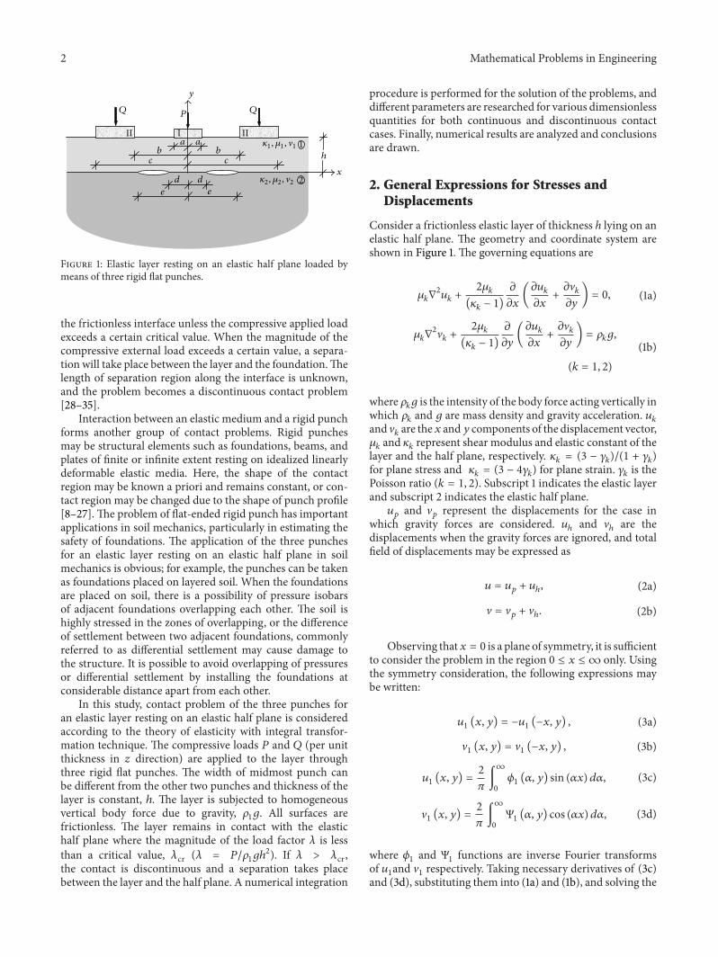
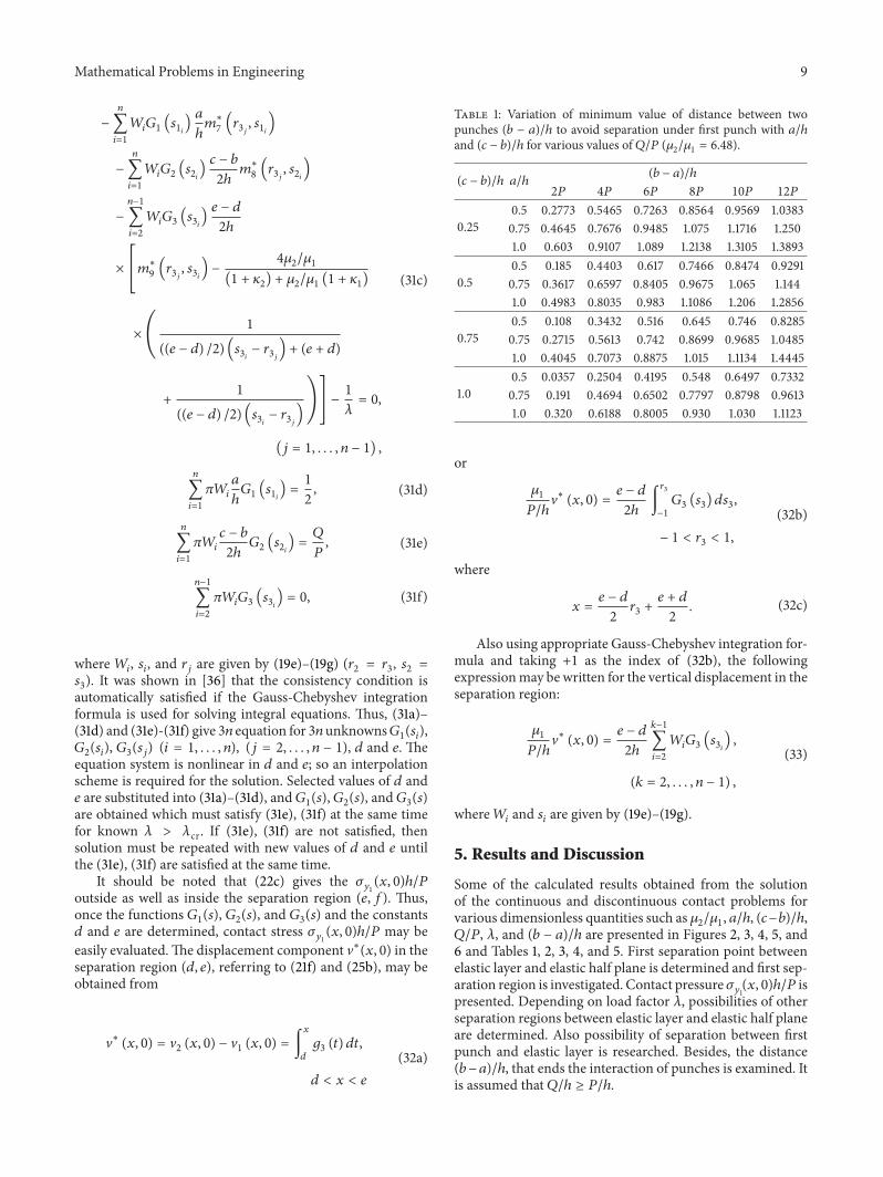
Figure 2 shows limit distance between punches that initi-ates separation under first punch for various values of mate-rial constant,𝜇
2/𝜇1with𝑄/𝑃.Thedistance (𝑏−𝑎)/ℎ increases,
maintaining continuous contact between first punch andelastic layer with 𝑄/𝑃. Besides, for bigger values of 𝜇
2/𝜇1,
limit distance that initiates separation under first punchdecreases. In such a case, elastic half plane gets stiffer and itbecomes easy to separate first punch from the elastic layer.
Variation of critical distance between punches with 𝑎/ℎand (𝑐 − 𝑏)/ℎ for various values of 𝑄/𝑃 is presented inTable 1. For fixed values of second punch width, (𝑐 − 𝑏)/ℎ,an increase in first punch width requires longer distancebetween punches to avoid separation under first punch. Onthe contrary, for fixed values of first punch width, 𝑎/ℎ,an increase in second punch width decreases (𝑏 − 𝑎)/ℎ
and punches can be placed closer to each other withoutseparation.
Interaction between punches ends for a definite value of(𝑏 − 𝑎)/ℎ. Tables 2–4 show the critical value of the distancethat ends interaction between punches with dimensionlessquantities 𝜇
2/𝜇1, 𝑎/ℎ, (𝑐 − 𝑏)/ℎ, and 𝑄/𝑃. In such a case,
there is no need to consider punches together. Also thesetables show the values of the load factor that cause separationbetween elastic layer and elastic half plane, 𝜆cr. For 𝜆 = 𝜆cr,𝜎𝑦1(𝑥, 0)ℎ/𝑃 is zero. Contact between punches and elastic
layer is continuous.Table 3 shows the critical distance between punches that
ends interaction of punches with elastic constant, 𝜇2/𝜇1. For
small values of 𝜇2/𝜇1; that is, it is easy to bend elastic layer,
interaction between punches ends in a longer distance. Initialseparation point 𝑥cr between elastic layer and elastic halfplane from the origin 𝑥 = 0 decreases with an increase in𝜇2/𝜇1. Critical load factor also decreases in this situation.
Distance (𝑏−𝑎)/ℎ that ends interaction between punchesincreases with a decrease in second punch width while firstpunch width is fixed. If both first and second widths areincreased, interaction of punches ends in a shorter distance.This situation is presented in Table 4. In this case, critical loadfactor, 𝜆cr increases but initial separation point, 𝑥cr decreaseswith increment in punchwidths. Separation also occurs at theright-hand side of the second punch.
For fixed values of 𝑎/ℎ = 0.5, (𝑐 − 𝑏)/ℎ = 1, 𝑄 = 2𝑃,and 𝜇
2/𝜇1= 1.65, variations of critical load factor, 𝜆cr and
initial separation point, 𝑥cr are given in Table 5. For smallvalues of (𝑏 − 𝑎)/ℎ, initial separation point between elasticlayer and elastic half plane appears at the right-hand side ofsecond punch. If (𝑏 − 𝑎)/ℎ increases, in this case separationtakes place between two punches. Keeping on increasing,the distance (𝑏 − 𝑎)/ℎ ends the interaction of punches. For(𝑏 − 𝑎)/ℎ = 7.9446, there is no need to consider punchestogether.
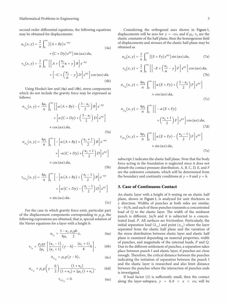
In Figures 3–5, the normalized contact stress distribution𝜎𝑦1(𝑥, 0)ℎ/𝑃 at the interface of elastic layer and elastic half
plane is given for the problems described in Section 3, andSection 4. Different scales have been used for continuous anddiscontinuous contact cases in order to include the entirepressure distribution and to give sufficient details in compactforms.
Mathematical Problems in Engineering 11
Table 4: Variation of distance between two punches (𝑏−𝑎)/ℎ that ends interaction of punches with 𝑎/ℎ and (𝑐−𝑏)/ℎ (𝑄 = 4𝑃, 𝜇2/𝜇1= 0.36).
𝑎/ℎ (𝑐 − 𝑏)/ℎ (𝑏 − 𝑎)/ℎPunch I Punch II
𝜆crright (𝑥crright − 𝑎)/ℎ 𝜆crleft = 𝜆crright (𝑏 − 𝑥crleft )/ℎ = (𝑥crright − 𝑐)/ℎ
0.25 1.5 10.8345 150.2590 3.775 54.1240 3.38160.25 1.0 11.8775 164.4214 3.655 49.0259 3.44950.25 0.5 12.7008 169.3000 3.628 45.9626 3.59680.50 1.0 11.6754 173.4645 3.523 49.0235 3.44940.75 1.5 10.4960 176.6011 3.421 54.1289 3.3810
0
0.6
1.2
1.8
2.4
0.3
0.9
1.5
2.1(1)
(2)
(3)
(4)
(𝑏−𝑎)/ℎ
𝑄/𝑃
5 10 15 207.5 12.5 17.5
(3) 𝜇2/𝜇1 = 2.75(1) 𝜇2/𝜇1 = 0.61(2) 𝜇2/𝜇1 = 1.65 (4) 𝜇2/𝜇1 = 6.48
Figure 2: Variation of minimum value of distance between twopunches (𝑏 − 𝑎)/ℎ to avoid separation under first punch with 𝑄/𝑃for various values of 𝜇
2/𝜇1(𝑎/ℎ = 0.5, (𝑐 − 𝑏)/ℎ = 1).
Table 5: Variation of load factor values with distance between twopunches (𝑏 − 𝑎)/ℎ (𝑄 = 2𝑃, 𝜇
2/𝜇1= 1.65, 𝑎/ℎ = 0.5, and (𝑐 − 𝑏)/ℎ =
1).
(𝑏 − 𝑎)/ℎPunch I Punch II
𝜆crright 𝑥crright 𝜆crleft 𝑥crleft 𝜆crright 𝑥crright
0.5 30.6814 4.2941 32.4279 4.8063 34.0783 6.8085 28.4331 3.167 28.4331 3.167 34.2756 8.8036 32.0727 4.184 32.0727 4.184 34.3055 9.8017 33.8531 5.211 33.8531 5.211 34.3175 10.8007.9446 123.1714 2.835 34.3182 6.148 34.3182 11.743
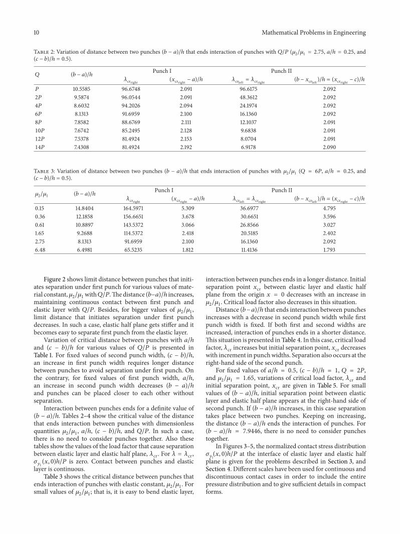
Variation of the contact stress distribution 𝜎𝑦1(𝑥, 0)ℎ/𝑃
with load factor 𝜆 = 𝑃/𝜌1𝑔ℎ2 for fixed values of 𝑄 = 2𝑃,
(1)
(3) (3) (2)
0 1.5 3 4.5 6 7.5 9 10.5 12𝑥/ℎ
0−0.011−0.022−0.05
−0.4
−0.6
−0.8
−1
−1.2
−1.4
−1.6(1), (2), (3)
(2) 𝜆 = 𝜆cr = 45.894 (𝑥cr = 4.327)(𝑑/ℎ = 3.66, 𝑒/ℎ = 5.926)(1) 𝜆 = 90 > 𝜆cr
(3) 𝜆 = 20 < 𝜆cr
(𝜎𝑦1(𝑥,0))/(𝑃/ℎ)
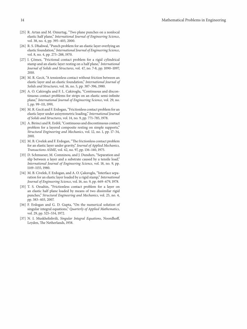
Figure 3: Contact stress distribution between elastic layer andelastic half plane for the cases of continuous (𝜆 < 𝜆cr) anddiscontinuous contact (𝜆 > 𝜆cr) (𝑄 = 2𝑃, 𝜇
2/𝜇1= 2.75, 𝑎/ℎ = 0.25,
(𝑏 − 𝑎)/ℎ = 1.5, and (𝑐 − 𝑏)/ℎ = 0.5).
𝜇2/𝜇1= 2.75, 𝑎/ℎ = 0.25, (𝑏−𝑎)/ℎ = 1.5, and (𝑐−𝑏)/ℎ = 0.5 is
presented in Figure 3, 𝜆 < 𝜆cr and 𝜆 > 𝜆cr show contact stressdistribution for the continuous and discontinuous contactcases, respectively. It can be seen from the figure that anotherseparation region is possible if distance between punches(𝑏 − 𝑎)/ℎ or load factor 𝜆 is increased. Contact pressure haspeaks around the edges of the rigid punches.
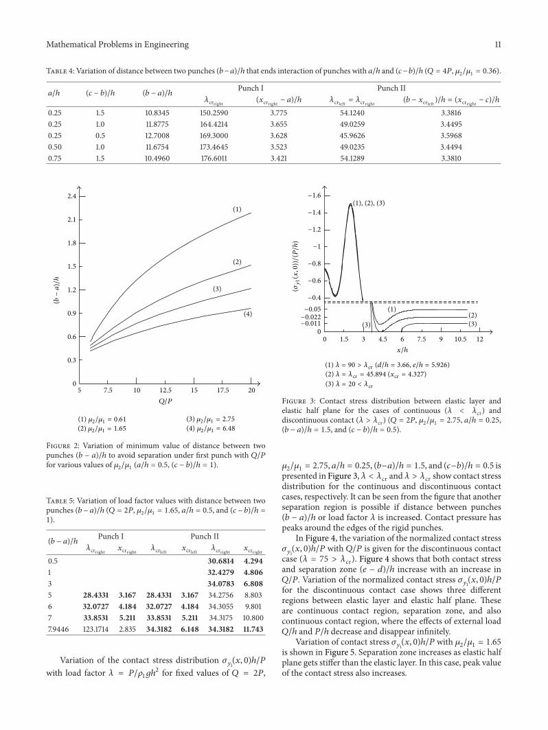
In Figure 4, the variation of the normalized contact stress𝜎𝑦1(𝑥, 0)ℎ/𝑃 with 𝑄/𝑃 is given for the discontinuous contact
case (𝜆 = 75 > 𝜆cr). Figure 4 shows that both contact stressand separation zone (𝑒 − 𝑑)/ℎ increase with an increase in𝑄/𝑃. Variation of the normalized contact stress 𝜎
𝑦1(𝑥, 0)ℎ/𝑃
for the discontinuous contact case shows three differentregions between elastic layer and elastic half plane. Theseare continuous contact region, separation zone, and alsocontinuous contact region, where the effects of external load𝑄/ℎ and 𝑃/ℎ decrease and disappear infinitely.
Variation of contact stress 𝜎𝑦1(𝑥, 0)ℎ/𝑃 with 𝜇
2/𝜇1= 1.65
is shown in Figure 5. Separation zone increases as elastic halfplane gets stiffer than the elastic layer. In this case, peak valueof the contact stress also increases.
12 Mathematical Problems in Engineering
(3)
(2)
(1)
(3) (1)
(2) (1) (3)
(2)
0 2 4 6 8 10 12 14 16𝑥/ℎ
0
−0.013
−1
−1.5
−2
−2.5
−3
(2) 𝑄 = 3𝑃(3) 𝑄 = 4𝑃
(1) 𝑄 = 2𝑃 (𝑑ℎ = 3.634, 𝑒/ℎ = 6.085)(𝑑ℎ = 3.396, 𝑒/ℎ = 7.245)(𝑑ℎ = 3.27, 𝑒/ℎ = 8.153)
(𝜎𝑦1(𝑥,0))/(𝑃/ℎ)
Figure 4: Contact stress distribution between elastic layer andelastic half plane for the case of discontinuous contact (𝜇
2/𝜇1= 0.36,
𝑎/ℎ = 0.125, (𝑏 − 𝑎)/ℎ = 0.5, (𝑐 − 𝑏)/ℎ = 0.5, and 𝜆 = 75 > 𝜆cr).
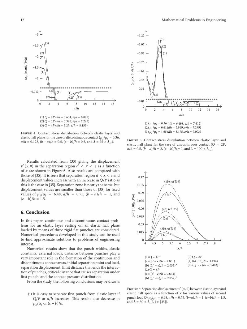
Results calculated from (33) giving the displacementV∗(𝑥, 0) in the separation region 𝑑 < 𝑥 < 𝑒 as a functionof 𝑥 are shown in Figure 6. Also results are compared withthose of [35]. It is seen that separation region 𝑑 < 𝑥 < 𝑒 anddisplacement values increase with an increase in𝑄/𝑃 ratio asthis is the case in [35]. Separation zone is nearly the same, butdisplacement values are smaller than those of [35] for fixedvalues of 𝜇
2/𝜇1= 6.48, 𝑎/ℎ = 0.75, (𝑏 − 𝑎)/ℎ = 1, and
(𝑐 − 𝑏)/ℎ = 1.5.
6. Conclusion
In this paper, continuous and discontinuous contact prob-lems for an elastic layer resting on an elastic half planeloaded by means of three rigid flat punches are considered.Numerical procedures developed in this study can be usedto find approximate solutions to problems of engineeringinterest.
Numerical results show that the punch widths, elasticconstants, external loads, distance between punches play avery important role in the formation of the continuous anddiscontinuous contact areas, initial separation point and load,separation displacement, limit distance that ends the interac-tion of punches, critical distance that causes separation underfirst punch, and the contact pressure distribution.
From the study, the following conclusions may be drawn:
(i) it is easy to separate first punch from elastic layer if𝑄/𝑃 or 𝑎/ℎ increases. This results also decrease in𝜇2/𝜇1or (𝑐 − 𝑏)/ℎ.
(3)
(2) (3) (2)
(3)
(2)
(1)
(1)
(1) (3) 0 2 4 6 8 10 12 14 16
0−0.01
−0.31
−0.46
−0.61
−0.76
−0.92
−1.07
−1.22
(1) 𝜇2/𝜇1 = 0.36(2) 𝜇2/𝜇1 = 0.61(3) 𝜇2/𝜇1 = 1.65
(𝑑ℎ = 6.498, 𝑒/ℎ = 7.612)(𝑑ℎ = 5.869, 𝑒/ℎ = 7.299)(𝑑ℎ = 5.175, 𝑒/ℎ = 7.003)
𝑥/ℎ
(𝜎𝑦1(𝑥,0))/(𝑃/ℎ)
Figure 5: Contact stress distribution between elastic layer andelastic half plane for the case of discontinuous contact (𝑄 = 2𝑃,𝑎/ℎ = 0.5, (𝑏 − 𝑎)/ℎ = 2, (𝑐 − 𝑏)/ℎ = 1, and 𝜆 = 100 > 𝜆cr).
(1b) ref [35]
(1a)
(2b) ref [35]
(2a)
(3b) ref [35]
(3a) 0
0.03
0.06
0.09
0.105
0.12
0.075
0.045
0.015
4 4.5 5 5.5 6 6.5 7 7.5 8𝑥/ℎ
(1) 𝑄 = 4𝑃(a) ((𝑑 − 𝑒)/ℎ = 2.001)(b) ((𝑓 − 𝑒)/ℎ = 2.033)∗
(2) 𝑄 = 6𝑃(a) ((𝑑 − 𝑒)/ℎ = 2.854)(b) ((𝑓 − 𝑒)/ℎ = 2.857)∗
(3) 𝑄 = 8𝑃(a) ((𝑑 − 𝑒)/ℎ = 3.494)(b) ((𝑓 − 𝑒)/ℎ = 3.483)∗
(𝜇�∗(𝑥,0))/(𝑃/ℎ)
Figure 6: Separation displacement V∗(𝑥, 0) between elastic layer andelastic half space as a function of 𝑥 for various values of secondpunch load𝑄 (𝜇
2/𝜇1= 6.48, 𝑎/ℎ = 0.75, (𝑏−𝑎)/ℎ = 1, (𝑐−𝑏)/ℎ = 1.5,
and 𝜆 = 50 > 𝜆cr), (∗: [35]).
Mathematical Problems in Engineering 13
(ii) Increment in 𝑄/𝑃, 𝑎/ℎ or (𝑐 − 𝑏)/ℎ ends interactionof punches in a shorter distance. Also an increase in𝜇2/𝜇1causes the same result.
(iii) First separation between elastic layer and elastic halfplane occurs between punches or in the region 𝑐 <
𝑥 < ∞ depending on 𝜆. If (𝑏 − 𝑎)/ℎ is big enough,interaction of punches disappears.
(iv) Size of separation region is not affected much with𝑄/𝑃, but separation displacement is increasedwith anincrease in 𝑄/𝑃.
Nomenclature
𝑃: Compressive load per unit thickness in 𝑧direction on punch I, (N/m)
𝑄: Compressive load per unit thickness in 𝑧direction on punch II and punch III,(N/m)
ℎ: Thickness of the layer, (m)𝜆: Load factor𝑢: 𝑥-component of the displacement, (m)V: 𝑦-component of the displacement, (m)𝜌𝑘: Mass density, (kg/m3)
𝑔: Gravity acceleration, (m/sn2)𝜇: Shear modulus, (Pa)𝜅: Elastic constant𝛾: Poisson’s ratio(𝑐 − 𝑏): Width of punch II and punch III, (m)𝑎: Half width of punch I, (m)𝑃(𝑥): Contact pressure under punch I, (Pa)𝑄(𝑥): Contact pressure under punch II and
punch III, (Pa)(𝑒 − 𝑑): Separation length, (m).
References
[1] P. Wriggers, Computational Contact Mechanics, John Wiley &Sons, Chichester, UK, 2002.
[2] M. R. Gecit, “The axisymmetric double contact problem fora frictionless elastic layer indented by an elastic cylinder,”International Journal of Engineering Science, vol. 24, no. 9, pp.1571–1584, 1986.
[3] V. Kahya, T. S. Ozsahin, A. Birinci, and R. Erdol, “A recedingcontact problem for an anisotropic elastic medium consistingof a layer and a half plane,” International Journal of Solids andStructures, vol. 44, no. 17, pp. 5695–5710, 2007.
[4] I. Comez, A. Birinci, and R. Erdol, “Double receding contactproblem for a rigid stamp and two elastic layers,” EuropeanJournal of Mechanics, A/Solids, vol. 23, no. 2, pp. 301–309, 2004.
[5] L. M. Keer, J. Dondurs, and K. C. Tsai, “Problems involving areceding contact between a layer and a half space,” Journal ofApplied Mechanics, Transactions ASME, vol. 39, no. 4, pp. 1115–1120, 1972.
[6] F. Erdogan andM. Ratwani, “The contact problem for an elasticlayer supported by two elastic quarter planes,” Journal of AppliedMechanics, Transactions ASME, vol. 41, no. 3, pp. 673–678, 1974.
[7] M. B. Civelek and F. Erdogan, “The axisymmetric doublecontact problem for a frictionless elastic layer,” InternationalJournal of Solids and Structures, vol. 10, no. 6, pp. 639–659, 1974.
[8] Q. Lan, G. A. C. Graham, and A. P. S. Selvadurai, “Certain two-punch problems for an elastic layer,” International Journal ofSolids and Structures, vol. 33, no. 19, pp. 2759–2774, 1996.
[9] M. J. Jaffar, “Frictionless contact between an elastic layer on arigid base and a circular flat-ended punch with rounded edgeor a conical punch with rounded tip,” International Journal ofMechanical Sciences, vol. 44, no. 3, pp. 545–560, 2002.
[10] G. Fu andA.Chandra, “Normal indentation of elastic half-spacewith a rigid frictionless axisymmetric punch,” Journal of AppliedMechanics, Transactions ASME, vol. 69, no. 2, pp. 142–147, 2002.
[11] Y. Pinyochotiwong, J. Rungamornrat, and T. Senjuntichai,“Analysis of rigid frictionless indentation on half-space withsurface elasticity,” in Proceedings of the 12th East Asia-PasificConference on Structural Engineering and Construction, vol. 14,pp. 2403–2410, 2011.
[12] G. M. L. Gladwell, “On some unbonded contact problems inplane elasticity theory,” Journal of Applied Mechanics, Transac-tions ASME, vol. 43, no. 2, pp. 263–267, 1976.
[13] O. I. Zhupanska, “Contact problem for elastic spheres: applica-bility of the Hertz theory to non-small contact areas,” Interna-tional Journal of Engineering Science, vol. 49, no. 7, pp. 576–588,2011.
[14] M. Porter and D. A. Hills, “A flat punch pressed against anelastic interlayer under conditions of slip and separation,”International Journal of Mechanical Sciences, vol. 44, no. 3, pp.465–474, 2002.
[15] M. R. . Gecit and S. Gokpınar, “Frictionless contact between anelastic layer and a rigid rounded support,” Arabian Journal ofScience and Engineering, vol. 10, no. 3, pp. 243–251, 1985.
[16] F. Yang, “Adhesive contact between an elliptical rigid flat-endedpunch and an elastic half space,” Journal of Physics D, vol. 38, no.8, pp. 1211–1214, 2005.
[17] M. I. Porter and D. A. Hills, “Note on the complete contactbetween a flat rigid punch and an elastic layer attached toa dissimilar substrate,” International Journal of MechanicalSciences, vol. 44, no. 3, pp. 509–520, 2002.
[18] M. E. R. Shanahan, “Adhesion of a punch to a thin membrane,”Comptes Rendus de l’Academie des Sciences IV, vol. 1, no. 4, pp.517–522, 2000.
[19] A. Klarbring, A. Mikelic, and M. Shillor, “The rigid punchproblem with friction,” International Journal of EngineeringScience, vol. 29, no. 6, pp. 751–768, 1991.
[20] V. I. Fabrikant andT. S. Sankar, “Concentrated force underneatha punch bonded to a transversely isotropic half-space,” Interna-tional Journal of Engineering Science, vol. 24, no. 1, pp. 111–117,1986.
[21] S. Karuppanan, C. M. Churchman, D. A. Hills, and E. Giner,“Sliding frictional contact between a square block and anelastically similar half-plane,” European Journal of Mechanics,A/Solids, vol. 27, no. 3, pp. 443–459, 2008.
[22] I. Comez and R. Erdol, “Frictional contact problem of a rigidstamp and an elastic layer bonded to a homogeneous substrate,”Archive of Applied Mechanics, vol. 83, no. 1, pp. 15–24, 2013.
[23] A. P. S. Selvadurai, “Mechanics of a rigid circular disc bonded toa cracked elastic half-space,” International Journal of Solids andStructures, vol. 39, no. 24, pp. 6035–6053, 2002.
[24] A. P. S. Selvadurai, “Boussinesq indentation of an isotropicelastic halfspace reinforced with an inextensible membrane,”International Journal of Engineering Science, vol. 47, no. 11-12, pp.1339–1345, 2009.
14 Mathematical Problems in Engineering
[25] R. Artan and M. Omurtag, “Two plane punches on a nonlocalelastic half plane,” International Journal of Engineering Science,vol. 38, no. 4, pp. 395–403, 2000.
[26] R. S. Dhaliwal, “Punch problem for an elastic layer overlying anelastic foundation,” International Journal of Engineering Science,vol. 8, no. 4, pp. 273–288, 1970.
[27] I. Comez, “Frictional contact problem for a rigid cylindricalstamp and an elastic layer resting on a half plane,” InternationalJournal of Solids and Structures, vol. 47, no. 7-8, pp. 1090–1097,2010.
[28] M. R. Gecit, “A tensionless contact without friction between anelastic layer and an elastic foundation,” International Journal ofSolids and Structures, vol. 16, no. 5, pp. 387–396, 1980.
[29] A. O. Cakiroglu and F. L. Cakiroglu, “Continuous and discon-tinuous contact problems for strips on an elastic semi-infiniteplane,” International Journal of Engineering Science, vol. 29, no.1, pp. 99–111, 1991.
[30] M. R. Gecit and F. Erdogan, “Frictionless contact problem for anelastic layer under axisymmetric loading,” International Journalof Solids and Structures, vol. 14, no. 9, pp. 771–785, 1978.
[31] A. Birinci and R. Erdol, “Continuous and discontinuous contactproblem for a layered composite resting on simple supports,”Structural Engineering and Mechanics, vol. 12, no. 1, pp. 17–34,2001.
[32] M. B. Civelek and F. Erdogan, “The frictionless contact problemfor an elastic layer under gravity,” Journal of Applied Mechanics,Transactions ASME, vol. 42, no. 97, pp. 136–140, 1975.
[33] D. Schmueser, M. Comninou, and J. Dundurs, “Separation andslip between a layer and a substrate caused by a tensile load,”International Journal of Engineering Science, vol. 18, no. 9, pp.1149–1155, 1980.
[34] M. B. Civelek, F. Erdogan, and A. O. Cakıroglu, “Interface sepa-ration for an elastic layer loaded by a rigid stamp,” InternationalJournal of Engineering Science, vol. 16, no. 9, pp. 669–679, 1978.
[35] T. S. Ozsahin, “Frictionless contact problem for a layer onan elastic half plane loaded by means of two dissimilar rigidpunches,” Structural Engineering and Mechanics, vol. 25, no. 4,pp. 383–403, 2007.
[36] F. Erdogan and G. D. Gupta, “On the numerical solution ofsingular integral equations,” Quarterly of Applied Mathematics,vol. 29, pp. 525–534, 1972.
[37] N. I. Muskhelishvili, Singular Integral Equations, Noordhoff,Leyden, The Netherlands, 1958.

Submit your manuscripts athttp://www.hindawi.com
Hindawi Publishing Corporationhttp://www.hindawi.com Volume 2014
MathematicsJournal of
Hindawi Publishing Corporationhttp://www.hindawi.com Volume 2014
Mathematical Problems in Engineering
Hindawi Publishing Corporationhttp://www.hindawi.com
Differential EquationsInternational Journal of
Volume 2014
Applied MathematicsJournal of
Hindawi Publishing Corporationhttp://www.hindawi.com Volume 2014
Probability and StatisticsHindawi Publishing Corporationhttp://www.hindawi.com Volume 2014
Journal of
Hindawi Publishing Corporationhttp://www.hindawi.com Volume 2014
Mathematical PhysicsAdvances in
Complex AnalysisJournal of
Hindawi Publishing Corporationhttp://www.hindawi.com Volume 2014
OptimizationJournal of
Hindawi Publishing Corporationhttp://www.hindawi.com Volume 2014
CombinatoricsHindawi Publishing Corporationhttp://www.hindawi.com Volume 2014
International Journal of
Hindawi Publishing Corporationhttp://www.hindawi.com Volume 2014
Operations ResearchAdvances in
Journal of
Hindawi Publishing Corporationhttp://www.hindawi.com Volume 2014
Function Spaces
Abstract and Applied AnalysisHindawi Publishing Corporationhttp://www.hindawi.com Volume 2014
International Journal of Mathematics and Mathematical Sciences
Hindawi Publishing Corporationhttp://www.hindawi.com Volume 2014
The Scientific World JournalHindawi Publishing Corporation http://www.hindawi.com Volume 2014
Hindawi Publishing Corporationhttp://www.hindawi.com Volume 2014
Algebra
Discrete Dynamics in Nature and Society
Hindawi Publishing Corporationhttp://www.hindawi.com Volume 2014
Hindawi Publishing Corporationhttp://www.hindawi.com Volume 2014
Decision SciencesAdvances in
Discrete MathematicsJournal of
Hindawi Publishing Corporationhttp://www.hindawi.com
Volume 2014 Hindawi Publishing Corporationhttp://www.hindawi.com Volume 2014
Stochastic AnalysisInternational Journal of
![arXiv:math-ph/0203017v2 12 Mar 2002 · ing converts a boundary-layer problem, which is a singular perturbation problem, into a regular perturbation problem [10–12]. A boundary-layer](https://img.dokumen.tips/doc/110x75/5e1f6122db782747ad5d989a/arxivmath-ph0203017v2-12-mar-2002-ing-converts-a-boundary-layer-problem-which.jpg)


![THE ELASTIC TORSION PROBLEM: SOLUTIONS IN ...harder problems like elastic-plastic torsion problem (e.g. [Fri]), and as a function against which solutions of harder problems are compared](https://img.dokumen.tips/doc/110x75/61447e3db5d1170afb43e8dd/the-elastic-torsion-problem-solutions-in-harder-problems-like-elastic-plastic.jpg)
![Beam stability on an elastic foundation subjected to ... · An elastic stability problem of non-conservative ... ported Timoshenko's beam [8]. Recently, Maurizi and Bambill verified](https://img.dokumen.tips/doc/110x75/5acb28367f8b9a73128b4fe2/beam-stability-on-an-elastic-foundation-subjected-to-elastic-stability-problem.jpg)