Embed Size (px)
Citation preview
Research ArticleA Study on the Rheological Properties of RecycledRubber-Modified Asphalt Mixtures
Murat Karacasu,1 Volkan Okur,1 and Arzu Er2
1Department of Civil Engineering, Eskisehir Osmangazi University, 26480 Meselik, Eskisehir, Turkey2Department of Civil Engineering, Akdeniz University, 07058 Antalya, Turkey
Correspondence should be addressed to Volkan Okur; [email protected]
Received 14 August 2014; Accepted 17 September 2014
Academic Editor: Turhan Bilir
Copyright © 2015 Murat Karacasu et al.This is an open access article distributed under the Creative CommonsAttribution License,which permits unrestricted use, distribution, and reproduction in any medium, provided the original work is properly cited.
Using waste rubber in asphalt mixes has become a common practice in road construction. This paper presents the results of astudy on the rheological characteristics of rubber-modified asphalt (RMA) concrete under static and dynamic loading conditions.A number of static and dynamic creep tests were conducted on RMAmix specimens with different rubber sizes and contents, anda series of resonant column tests were conducted to evaluate the shear modulus and damping values. To simulate the stress-strainresponse of traffic-induced loading, the measurements were taken for different confining pressures and strain levels. The results ofthe study indicated that rubber modification increases stiffness and damping ratio, making it a very attractive material for use inroad construction. However the grain size of the rubber is very important. Although RMAmay cost up to 100% more than regularasphalt, the advantages it brings, such as an increased service life of the road and proper waste utilization contributing to a moresustainable infrastructure, may justify the added cost.
1. Introduction
Asphalt concrete is the leading paving material for roadsand runways. Understanding the characteristics of the asphaltbeing used in a project is important to ensure long-termperformance and stability. Various environmental conditionsand traffic-induced loadings must be taken into account inthe design stage. Sometimes the design does not result inacceptable, safe, and sound usability due to early deterio-ration. Several factors contribute to deterioration, such asthe quality of materials and construction, traffic loading onthe road, road geometry, and environmental conditions. Ingeneral, most of the deterioration is due to rutting or bottomup fatigue and thermal cracking. Enhancing the pavement lifeis possible with somemodifications if possible factors causingdeteriorations are taken into consideration during the designstage.
Plastomeric polymeric materials, such as polyethylene(PE) andpolypropylene (PP), have evoked considerable inter-est among engineers and manufacturers for use in roadpaving modification because of their viscoelastic properties
and good adhesion to mineral aggregates [1–4]. The mainpurpose of using polymers in asphalt concrete is to increasebinder stiffness at high service temperatures and reducestiffness at low service temperatures [5–7]. Polymers whichare used for the modification of asphalt concrete can bedivided into three main categories: thermoplastic elastomers,plastomers, and reactive polymers.Thermoplastic elastomersare apparently capable of high elastic response characteristicsand therefore resist permanent deformation by stretching andrecovering their initial shape on the modified binder layer,whereas plastomers and reactive polymers modify asphaltby forming a tough, rigid, three-dimensional network toincrease stiffness and decrease deformations [8, 9]. Because ofits suitability in these conditions, one of the leading polymermodifiers for bitumen among the larger group of copolymersis styrene-butadiene-styrene (SBS) block. SBS is a synthetichard rubber copolymer that is used in applications wheredurability is important and is often substituted in part fornatural rubber based on the comparative raw materials’ costs[10–15]. It belongs to the group of copolymers called blockcopolymers, in which the backbone chain is made up of three
Hindawi Publishing Corporatione Scientific World JournalVolume 2015, Article ID 258586, 9 pageshttp://dx.doi.org/10.1155/2015/258586
2 The Scientific World Journal
segments.Thefirst is a long chain of polystyrene, themiddle isa long chain of polybutadiene, and the last segment is anotherlong section of polystyrene.
SBS is a cost-effective material that is used to stretchdwindling natural rubber resources, especially in tire man-ufacturing. However the disposal of used automobile tireshas causedmany environmental and economic problems.Theannual global production of used tires estimated 17 milliontonnes in which China, European Union Countries, USA,Japan, and India lead the way to produce the largest amountsof tyre [16]. A small percentage of these tires are recappedor reused as lower-quality rubber, but around 80% of thesetires are accumulated in dumps, posing health hazards andadversely impacting the environment [17].
Due to its elastic nature, crumb rubber can be used inroad construction to improve deformation resistance. Rub-ber-modified asphalt (RMA) is a bituminous mix consistingof blended aggregates, recycled crumb rubber, and bitumen.It is found out that rubber structure is themost important fac-tor affecting elastic properties. Crumb rubber has a granulartexture and ranges in size from a very fine powder (<0.1mm)to coarse particles (>5mm). Choubane et al. [18] publishedthe findings from a ten-year study of RMA surfaces andconcluded that crumb rubber increases overall strength andreduces surface rutting. RMA has been known to improvethe rheological properties at low and high temperatures andprovides a lifespan that is up to three times longer thanconventional asphalt [19]. There are also other reasons whyrubber is useful in both highways and railways, such asdecreasing thermal instability, increasing resistance to low-temperature cracking, reduction of noise levels, and reduc-tion of vibrations generated by heavy axle loads [20, 21].
The focus of the test program was to examine the per-formance of asphalt concrete whenmixedwith crumb rubberas aggregate. Same type rubber in different sizes and shapeswas added to the mix without any modification to the bitu-men content. The study concentrated on the behavior ofadmixture under cyclic loadings. The digestion mechanismof the rubber sizes is not evaluated in this paper but shouldbe considered in the future research.
2. Experimental Procedure
The appropriate aggregate gradation for hot-mix bitumenwas designed according to the technical specifications of theGeneral Directorate of TurkishHighways (GDTH) 2006 [22].The aggregates have a mean grain size (𝐷
50) between 0.30
and 3.0mm and a coefficient of uniformity (𝐶𝑢) between 2.0
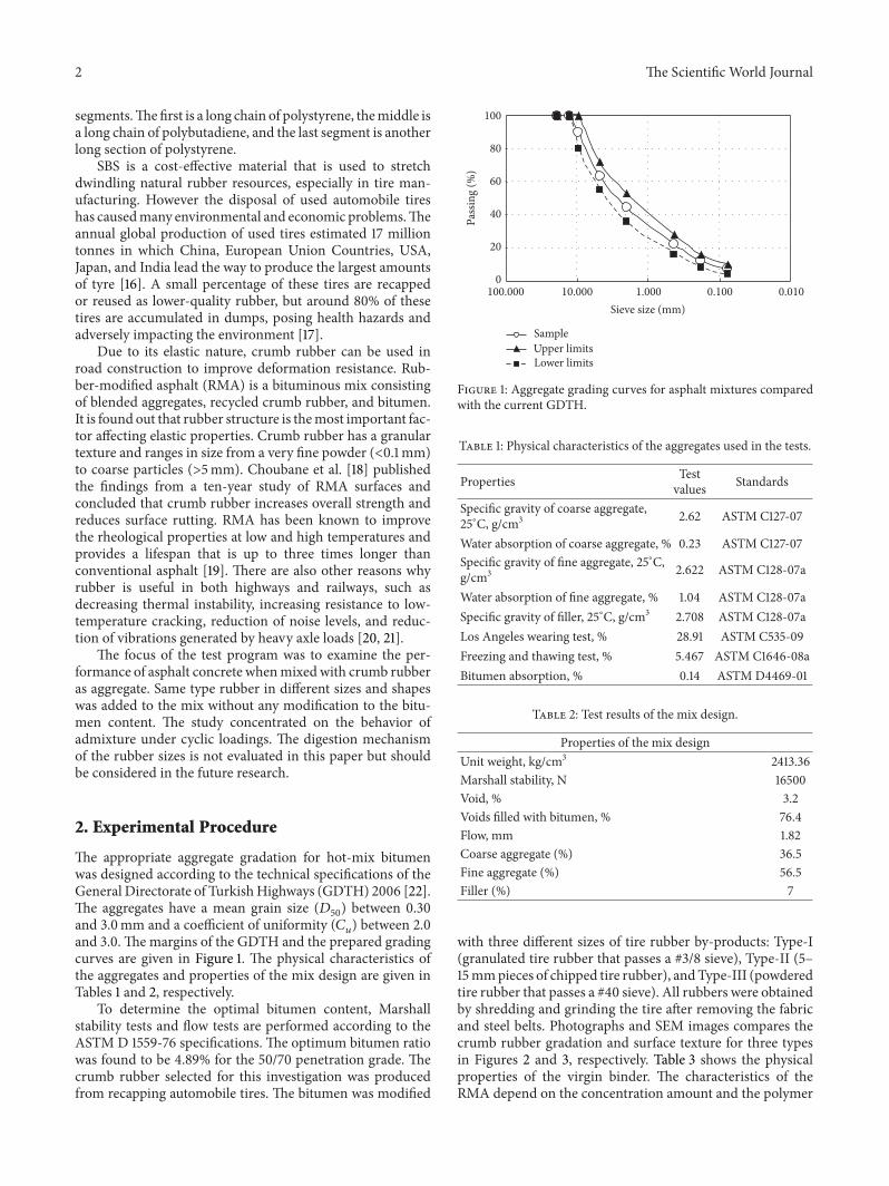
and 3.0. The margins of the GDTH and the prepared gradingcurves are given in Figure 1. The physical characteristics ofthe aggregates and properties of the mix design are given inTables 1 and 2, respectively.
To determine the optimal bitumen content, Marshallstability tests and flow tests are performed according to theASTM D 1559-76 specifications. The optimum bitumen ratiowas found to be 4.89% for the 50/70 penetration grade. Thecrumb rubber selected for this investigation was producedfrom recapping automobile tires. The bitumen was modified
0
20
40
60
80
100
0.0100.1001.00010.000100.000Sieve size (mm)
Pass
ing
(%)
Sample
Lower limitsUpper limits
Figure 1: Aggregate grading curves for asphalt mixtures comparedwith the current GDTH.
Table 1: Physical characteristics of the aggregates used in the tests.
Properties Testvalues Standards
Specific gravity of coarse aggregate,25∘C, g/cm3 2.62 ASTM C127-07
Water absorption of coarse aggregate, % 0.23 ASTM C127-07Specific gravity of fine aggregate, 25∘C,g/cm3 2.622 ASTM C128-07a
Water absorption of fine aggregate, % 1.04 ASTM C128-07aSpecific gravity of filler, 25∘C, g/cm3 2.708 ASTM C128-07aLos Angeles wearing test, % 28.91 ASTM C535-09Freezing and thawing test, % 5.467 ASTM C1646-08aBitumen absorption, % 0.14 ASTM D4469-01
Table 2: Test results of the mix design.
Properties of the mix designUnit weight, kg/cm3 2413.36Marshall stability, N 16500Void, % 3.2Voids filled with bitumen, % 76.4Flow, mm 1.82Coarse aggregate (%) 36.5Fine aggregate (%) 56.5Filler (%) 7
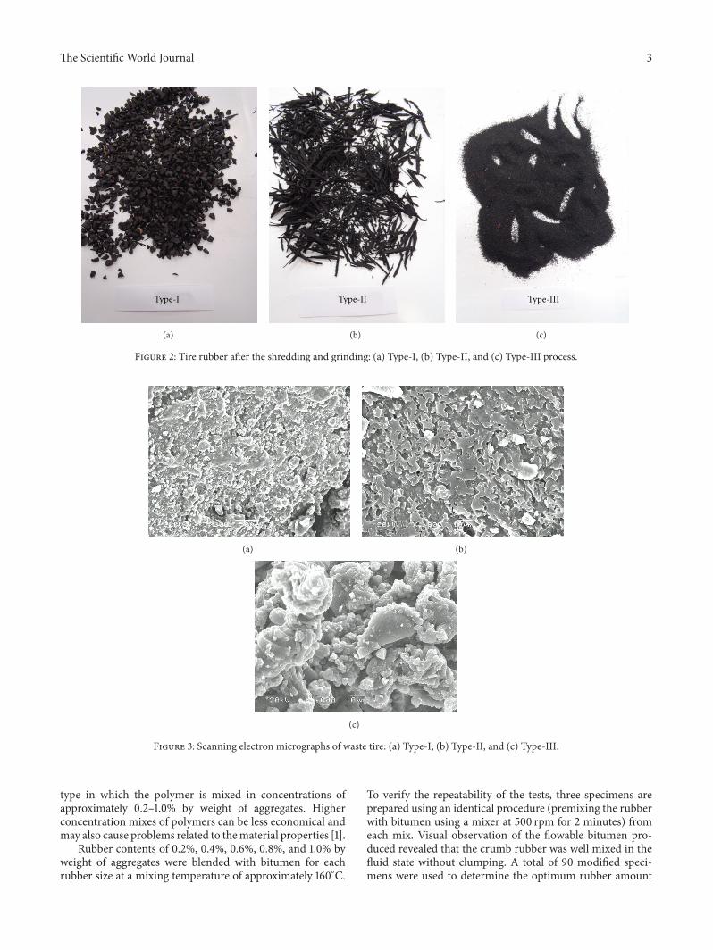
with three different sizes of tire rubber by-products: Type-I(granulated tire rubber that passes a #3/8 sieve), Type-II (5–15mmpieces of chipped tire rubber), andType-III (powderedtire rubber that passes a #40 sieve). All rubbers were obtainedby shredding and grinding the tire after removing the fabricand steel belts. Photographs and SEM images compares thecrumb rubber gradation and surface texture for three typesin Figures 2 and 3, respectively. Table 3 shows the physicalproperties of the virgin binder. The characteristics of theRMA depend on the concentration amount and the polymer
The Scientific World Journal 3
Type-I
(a)
Type-II
(b)
Type-III
(c)
Figure 2: Tire rubber after the shredding and grinding: (a) Type-I, (b) Type-II, and (c) Type-III process.
(a) (b)
(c)
Figure 3: Scanning electron micrographs of waste tire: (a) Type-I, (b) Type-II, and (c) Type-III.
type in which the polymer is mixed in concentrations ofapproximately 0.2–1.0% by weight of aggregates. Higherconcentration mixes of polymers can be less economical andmay also cause problems related to thematerial properties [1].
Rubber contents of 0.2%, 0.4%, 0.6%, 0.8%, and 1.0% byweight of aggregates were blended with bitumen for eachrubber size at a mixing temperature of approximately 160∘C.
To verify the repeatability of the tests, three specimens areprepared using an identical procedure (premixing the rubberwith bitumen using a mixer at 500 rpm for 2 minutes) fromeach mix. Visual observation of the flowable bitumen pro-duced revealed that the crumb rubber was well mixed in thefluid state without clumping. A total of 90 modified speci-mens were used to determine the optimum rubber amount
4 The Scientific World Journal
23.60
23.80
24.00
24.20
24.402.00
4.00
6.00
8.00
2 4 6 8 10
Air
void
s (%
)
Rubber content (%)
Uni
t wei
ght(
kN/m
3)
ControlType-I
Type-IIType-III
Figure 4: Variation in air voids and unit weight with respect torubber content.
Table 3: Properties of bitumen.
Properties Values Related standardsPenetration at 25∘C, 1/10mm 57.3 ASTM D 5-06e1Ductility at 25∘C, cm >100 ASTM D 113-99Loss on heating, % 0.17 ASTM D 6-95Specific gravity at 25∘C,gr/cm3 1.035 ASTM D 70-03
Softening point, ∘C 48.0 ASTM D 36-09Flash point, ∘C 308 ASTM D 92-02bElastic recovery, % (25∘C) 2.95 ASTM D 6084-06
for each type. In addition, 3 Control specimens with noadditives were prepared for comparison with the modifiedspecimens.
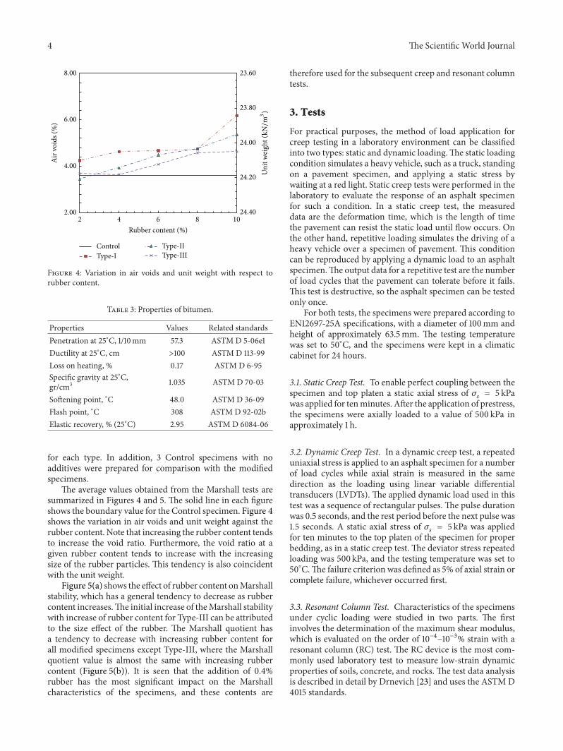
The average values obtained from the Marshall tests aresummarized in Figures 4 and 5. The solid line in each figureshows the boundary value for the Control specimen. Figure 4shows the variation in air voids and unit weight against therubber content. Note that increasing the rubber content tendsto increase the void ratio. Furthermore, the void ratio at agiven rubber content tends to increase with the increasingsize of the rubber particles. This tendency is also coincidentwith the unit weight.
Figure 5(a) shows the effect of rubber content onMarshallstability, which has a general tendency to decrease as rubbercontent increases.The initial increase of theMarshall stabilitywith increase of rubber content for Type-III can be attributedto the size effect of the rubber. The Marshall quotient hasa tendency to decrease with increasing rubber content forall modified specimens except Type-III, where the Marshallquotient value is almost the same with increasing rubbercontent (Figure 5(b)). It is seen that the addition of 0.4%rubber has the most significant impact on the Marshallcharacteristics of the specimens, and these contents are
therefore used for the subsequent creep and resonant columntests.
3. Tests
For practical purposes, the method of load application forcreep testing in a laboratory environment can be classifiedinto two types: static and dynamic loading.The static loadingcondition simulates a heavy vehicle, such as a truck, standingon a pavement specimen, and applying a static stress bywaiting at a red light. Static creep tests were performed in thelaboratory to evaluate the response of an asphalt specimenfor such a condition. In a static creep test, the measureddata are the deformation time, which is the length of timethe pavement can resist the static load until flow occurs. Onthe other hand, repetitive loading simulates the driving of aheavy vehicle over a specimen of pavement. This conditioncan be reproduced by applying a dynamic load to an asphaltspecimen.The output data for a repetitive test are the numberof load cycles that the pavement can tolerate before it fails.This test is destructive, so the asphalt specimen can be testedonly once.
For both tests, the specimens were prepared according toEN12697-25A specifications, with a diameter of 100mm andheight of approximately 63.5mm. The testing temperaturewas set to 50∘C, and the specimens were kept in a climaticcabinet for 24 hours.
3.1. Static Creep Test. To enable perfect coupling between thespecimen and top platen a static axial stress of 𝜎
𝑠= 5 kPa
was applied for tenminutes. After the application of prestress,the specimens were axially loaded to a value of 500 kPa inapproximately 1 h.
3.2. Dynamic Creep Test. In a dynamic creep test, a repeateduniaxial stress is applied to an asphalt specimen for a numberof load cycles while axial strain is measured in the samedirection as the loading using linear variable differentialtransducers (LVDTs). The applied dynamic load used in thistest was a sequence of rectangular pulses. The pulse durationwas 0.5 seconds, and the rest period before the next pulse was1.5 seconds. A static axial stress of 𝜎
𝑠= 5 kPa was applied
for ten minutes to the top platen of the specimen for properbedding, as in a static creep test. The deviator stress repeatedloading was 500 kPa, and the testing temperature was set to50∘C.The failure criterion was defined as 5% of axial strain orcomplete failure, whichever occurred first.
3.3. Resonant Column Test. Characteristics of the specimensunder cyclic loading were studied in two parts. The firstinvolves the determination of the maximum shear modulus,which is evaluated on the order of 10−4–10−3% strain with aresonant column (RC) test. The RC device is the most com-monly used laboratory test to measure low-strain dynamicproperties of soils, concrete, and rocks. The test data analysisis described in detail by Drnevich [23] and uses the ASTMD4015 standards.

The Scientific World Journal 5
10000
15000
20000
25000
2 4 6 8 10
Mar
shal
l sta
bilit
y (N
)
ControlType-I
Type-IIType-III
Rubber content (%)
(a)
0
2000
4000
6000
80000.00
1.00
2.00
3.00
4.00
2 4 6 8 10
Mar
shal
l quo
tient
(N/m
m)
Mar
shal
l flow
(mm
)
ControlType-I
Type-IIType-III
Rubber content (%)
(b)
Figure 5: Effect of rubber content on (a) Marshall stability and (b) Marshall flow and quotient.
The RC test configuration is a fixed-free systemwhere thespecimen is fixed at the bottom and free to rotate at the top atits fundamental frequency via a drive system. By measuringthe motion of the free end, the velocity of the propagatingwave and the degree of material damping can be derived.Theshearmodulus is then obtained from the derived velocity andthe density of the specimen.
The test specimen is a solid cylindrical specimen with anapproximate diameter-height ratio of 2. The bottom is fixedto the base of the apparatus. Sinusoidal torsional excitationis applied to the top of the specimen by an electric motorsystem. A torsional harmonic load of constant amplitude isapplied over a range of frequencies, and the response curve(strain amplitude) is calculated. The output angular accelera-tion at the top of the specimen is recorded by an accelerom-eter. The frequency of the cyclic torque is automatically andgradually changed until the first resonance of torsional vibra-tion is obtained.The shear wave velocity is obtained from thefirst-mode resonant frequency, and the shearmodulus is thencalculated using the shear wave velocity and the specimendensity.The shearmodulus anddamping ratioweremeasuredunder a range of shear strains. The power is shut off atresonance (i.e., forced vibration is removed), and thematerialdamping is determined from the free vibration decay.
The entire system is placed into a perspex chamber toapply a uniform confining pressure on the specimen using airpressure. A membrane covers the setup to prevent diffusionof air into the specimen. Identical fresh specimens wereprepared using the same procedure as for the Marshallstability tests. After the 300mm diameter cylindrical asphaltspecimen had cured, it was cored into a standard size with adiameter of 70mm for the resonant column test. The heightof the specimens was approximately 140mm.
The specimens were fixed onto the bottom pedestalusing cyanoacrylate-based fast-acting adhesive. Because thestrength and rigidity of the adhesive are higher than those
of the asphalt, they have almost no effect on the testing data.After the adhesive was cured, the RC device was set up. Eachspecimen was tested in sequence with stepwise increasedconfining pressure. At each confining pressure, cyclic torquewas applied to measure the shear modulus, 𝐺, and thedamping ratio, 𝐷. The vertical pressure on the subgradeunder a road is between 50 and 150 kPa when a car or loadedtruck axle passes over it. Thus, the tests were conducted byemploying four confining pressures of 𝜎
𝑐= 0, 50, 100, and
150 kPa. After the adjustment of each confining pressure ineach test, the cell pressure was maintained for 30 minutesto allow for volume change of the specimen before the teststarted.
4. Results and Discussion
The corresponding static creep stiffness plotted against theloading time is shown in Figure 6. One of the outcomes seenin Figure 6 is that the static creep stiffness is not appreciablyaffected by the duration of loading after a certain time.However, adding rubber to the mixture gradually changesthe strength properties of the specimens. This fact can beexplained by considering the structure of the specimen. Anasphalt specimen is composed of an assembly of aggregatesand bitumen, where intergranular forces are transmittedthrough points of contact. When rubber is added, the result-ing mixture is not always homogeneous at all contact pointsdue to the size and shape of the rubber. Furthermore, Type-Iand Type-II rubber types have relatively coarse-grained rub-ber crumbs, which have considerably smaller specific surfaceareas for a given size particle than in Type-III, and do notfully dissolve in the bitumenmixture, thereby increasing het-erogeneity and void ratio. Reacted asphalt rubber materialshave drastically different properties compared to unreactedasphalt rubber.The resolving of rubber increases the viscosity
6 The Scientific World Journal
0
100
200
300
400
500
600
0 1000 2000 3000 4000 5000
Cree
p sti
ffnes
s (M
Pa)
Loading time (s)
ControlType-IType-II
Type-III
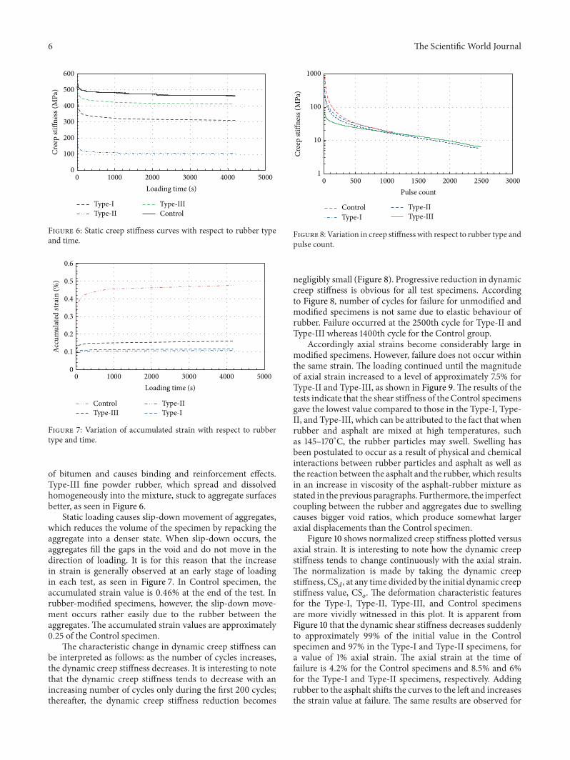
Figure 6: Static creep stiffness curves with respect to rubber typeand time.
0
0.1
0.2
0.3
0.4
0.5
0.6
0 1000 2000 3000 4000 5000
Accu
mul
ated
stra
in (%
)
Loading time (s)
ControlType-IType-II
Type-III
Figure 7: Variation of accumulated strain with respect to rubbertype and time.
of bitumen and causes binding and reinforcement effects.Type-III fine powder rubber, which spread and dissolvedhomogeneously into the mixture, stuck to aggregate surfacesbetter, as seen in Figure 6.
Static loading causes slip-down movement of aggregates,which reduces the volume of the specimen by repacking theaggregate into a denser state. When slip-down occurs, theaggregates fill the gaps in the void and do not move in thedirection of loading. It is for this reason that the increasein strain is generally observed at an early stage of loadingin each test, as seen in Figure 7. In Control specimen, theaccumulated strain value is 0.46% at the end of the test. Inrubber-modified specimens, however, the slip-down move-ment occurs rather easily due to the rubber between theaggregates. The accumulated strain values are approximately0.25 of the Control specimen.
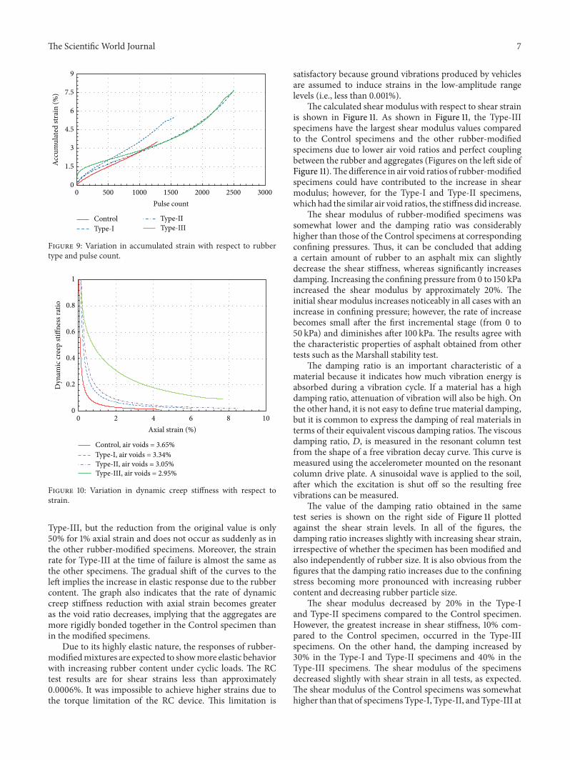
The characteristic change in dynamic creep stiffness canbe interpreted as follows: as the number of cycles increases,the dynamic creep stiffness decreases. It is interesting to notethat the dynamic creep stiffness tends to decrease with anincreasing number of cycles only during the first 200 cycles;thereafter, the dynamic creep stiffness reduction becomes
1
10
100
1000
0 500 1000 1500 2000 2500 3000
Cree
p sti
ffnes
s (M
Pa)
Pulse count
ControlType-I
Type-IIType-III
Figure 8: Variation in creep stiffness with respect to rubber type andpulse count.
negligibly small (Figure 8). Progressive reduction in dynamiccreep stiffness is obvious for all test specimens. Accordingto Figure 8, number of cycles for failure for unmodified andmodified specimens is not same due to elastic behaviour ofrubber. Failure occurred at the 2500th cycle for Type-II andType-III whereas 1400th cycle for the Control group.
Accordingly axial strains become considerably large inmodified specimens. However, failure does not occur withinthe same strain. The loading continued until the magnitudeof axial strain increased to a level of approximately 7.5% forType-II and Type-III, as shown in Figure 9.The results of thetests indicate that the shear stiffness of the Control specimensgave the lowest value compared to those in the Type-I, Type-II, and Type-III, which can be attributed to the fact that whenrubber and asphalt are mixed at high temperatures, suchas 145–170∘C, the rubber particles may swell. Swelling hasbeen postulated to occur as a result of physical and chemicalinteractions between rubber particles and asphalt as well asthe reaction between the asphalt and the rubber, which resultsin an increase in viscosity of the asphalt-rubber mixture asstated in the previous paragraphs. Furthermore, the imperfectcoupling between the rubber and aggregates due to swellingcauses bigger void ratios, which produce somewhat largeraxial displacements than the Control specimen.
Figure 10 shows normalized creep stiffness plotted versusaxial strain. It is interesting to note how the dynamic creepstiffness tends to change continuously with the axial strain.The normalization is made by taking the dynamic creepstiffness, CS
𝑑, at any time divided by the initial dynamic creep
stiffness value, CS𝑜. The deformation characteristic features
for the Type-I, Type-II, Type-III, and Control specimensare more vividly witnessed in this plot. It is apparent fromFigure 10 that the dynamic shear stiffness decreases suddenlyto approximately 99% of the initial value in the Controlspecimen and 97% in the Type-I and Type-II specimens, fora value of 1% axial strain. The axial strain at the time offailure is 4.2% for the Control specimens and 8.5% and 6%for the Type-I and Type-II specimens, respectively. Addingrubber to the asphalt shifts the curves to the left and increasesthe strain value at failure. The same results are observed for
The Scientific World Journal 7
0
1.5
3
4.5
6
7.5
9
0 500 1000 1500 2000 2500 3000
Accu
mul
ated
stra
in (%
)
Pulse count
ControlType-I
Type-IIType-III
Figure 9: Variation in accumulated strain with respect to rubbertype and pulse count.
0
0.2
0.4
0.6
0.8
1
0 2 4 6 8 10
Dyn
amic
cree
p sti
ffnes
s rat
io
Axial strain (%)
Control, air voids = 3.65%Type-I, air voids = 3.34%Type-II, air voids = 3.05%Type-III, air voids = 2.95%
Figure 10: Variation in dynamic creep stiffness with respect tostrain.
Type-III, but the reduction from the original value is only50% for 1% axial strain and does not occur as suddenly as inthe other rubber-modified specimens. Moreover, the strainrate for Type-III at the time of failure is almost the same asthe other specimens. The gradual shift of the curves to theleft implies the increase in elastic response due to the rubbercontent. The graph also indicates that the rate of dynamiccreep stiffness reduction with axial strain becomes greateras the void ratio decreases, implying that the aggregates aremore rigidly bonded together in the Control specimen thanin the modified specimens.
Due to its highly elastic nature, the responses of rubber-modifiedmixtures are expected to showmore elastic behaviorwith increasing rubber content under cyclic loads. The RCtest results are for shear strains less than approximately0.0006%. It was impossible to achieve higher strains due tothe torque limitation of the RC device. This limitation is
satisfactory because ground vibrations produced by vehiclesare assumed to induce strains in the low-amplitude rangelevels (i.e., less than 0.001%).
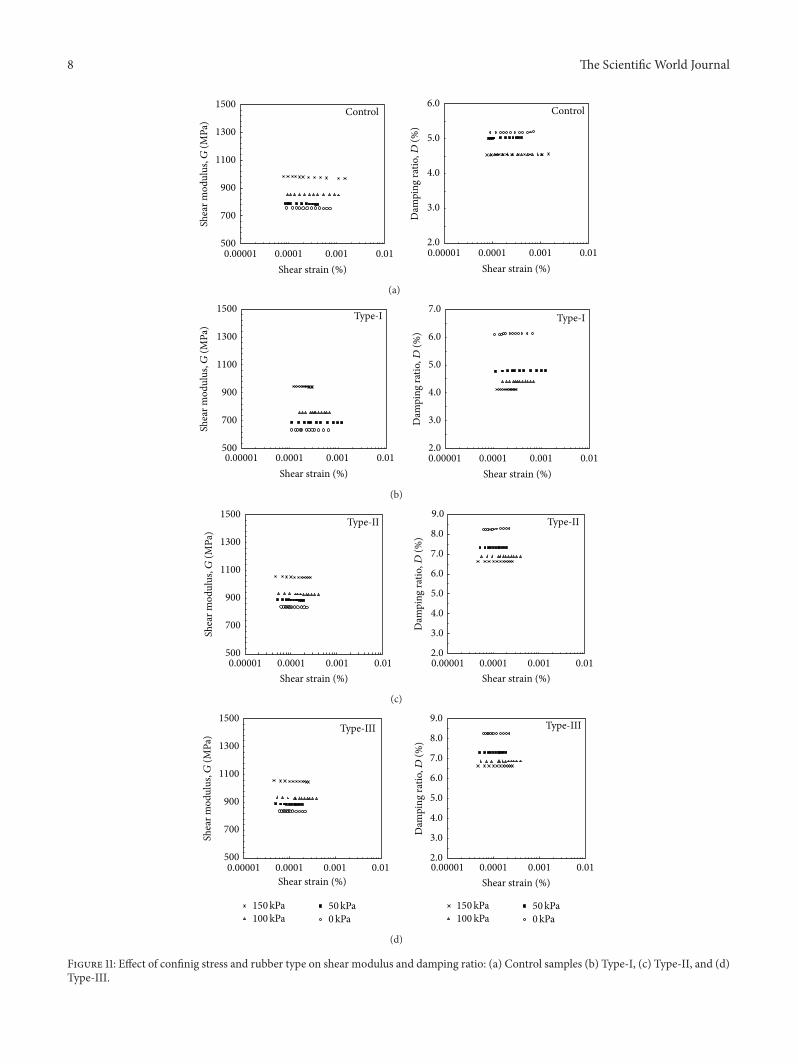
The calculated shear modulus with respect to shear strainis shown in Figure 11. As shown in Figure 11, the Type-IIIspecimens have the largest shear modulus values comparedto the Control specimens and the other rubber-modifiedspecimens due to lower air void ratios and perfect couplingbetween the rubber and aggregates (Figures on the left side ofFigure 11).Thedifference in air void ratios of rubber-modifiedspecimens could have contributed to the increase in shearmodulus; however, for the Type-I and Type-II specimens,which had the similar air void ratios, the stiffness did increase.
The shear modulus of rubber-modified specimens wassomewhat lower and the damping ratio was considerablyhigher than those of the Control specimens at correspondingconfining pressures. Thus, it can be concluded that addinga certain amount of rubber to an asphalt mix can slightlydecrease the shear stiffness, whereas significantly increasesdamping. Increasing the confining pressure from 0 to 150 kPaincreased the shear modulus by approximately 20%. Theinitial shear modulus increases noticeably in all cases with anincrease in confining pressure; however, the rate of increasebecomes small after the first incremental stage (from 0 to50 kPa) and diminishes after 100 kPa. The results agree withthe characteristic properties of asphalt obtained from othertests such as the Marshall stability test.
The damping ratio is an important characteristic of amaterial because it indicates how much vibration energy isabsorbed during a vibration cycle. If a material has a highdamping ratio, attenuation of vibration will also be high. Onthe other hand, it is not easy to define true material damping,but it is common to express the damping of real materials interms of their equivalent viscous damping ratios.The viscousdamping ratio, 𝐷, is measured in the resonant column testfrom the shape of a free vibration decay curve. This curve ismeasured using the accelerometer mounted on the resonantcolumn drive plate. A sinusoidal wave is applied to the soil,after which the excitation is shut off so the resulting freevibrations can be measured.
The value of the damping ratio obtained in the sametest series is shown on the right side of Figure 11 plottedagainst the shear strain levels. In all of the figures, thedamping ratio increases slightly with increasing shear strain,irrespective of whether the specimen has been modified andalso independently of rubber size. It is also obvious from thefigures that the damping ratio increases due to the confiningstress becoming more pronounced with increasing rubbercontent and decreasing rubber particle size.
The shear modulus decreased by 20% in the Type-Iand Type-II specimens compared to the Control specimen.However, the greatest increase in shear stiffness, 10% com-pared to the Control specimen, occurred in the Type-IIIspecimens. On the other hand, the damping increased by30% in the Type-I and Type-II specimens and 40% in theType-III specimens. The shear modulus of the specimensdecreased slightly with shear strain in all tests, as expected.The shear modulus of the Control specimens was somewhathigher than that of specimens Type-I, Type-II, andType-III at
8 The Scientific World Journal
500
700
900
1100
1300
1500
0.00001 0.0001 0.001 0.01
Control
2.0
3.0
4.0
5.0
6.0
0.00001 0.0001 0.001 0.01Shear strain (%)Shear strain (%)
Control
Shea
r mod
ulus
,G(M
Pa)
Dam
ping
ratio
,D(%
)
(a)
500
700
900
1100
1300
1500
0.00001 0.0001 0.001 0.012.0
3.0
4.0
5.0
6.0
7.0
0.00001 0.0001 0.001 0.01Shear strain (%)Shear strain (%)
Type-IType-I
Shea
r mod
ulus
,G(M
Pa)
Dam
ping
ratio
,D(%
)
(b)
Type-IIType-II
500
700
900
1100
1300
1500
0.00001 0.0001 0.001 0.012.0
3.0
4.0
5.0
6.0
7.0
8.0
9.0
0.00001 0.0001 0.001 0.01Shear strain (%)Shear strain (%)
Shea
r mod
ulus
,G(M
Pa)
Dam
ping
ratio
,D(%
)
(c)
Type-IIIType-III
500
700
900
1100
1300
1500
0.00001 0.0001 0.001 0.012.0
3.0
4.0
5.0
6.0
7.0
8.0
9.0
0.00001 0.0001 0.001 0.01Shear strain (%)Shear strain (%)
Shea
r mod
ulus
,G(M
Pa)
Dam
ping
ratio
,D(%
)
150kPa100 kPa
50kPa0kPa
150kPa100 kPa
50kPa0kPa
(d)
Figure 11: Effect of confinig stress and rubber type on shear modulus and damping ratio: (a) Control samples (b) Type-I, (c) Type-II, and (d)Type-III.
The Scientific World Journal 9
the corresponding confining pressures. The weak interactionbetween the rubber particle surface and the asphalt changesunder static or dynamic loads. Increased specific surfaceincreases the reaction rate with hot asphalt, as in the case ofthe Type-III specimens.
The aggregates in the asphalt concrete are extremely stiffand therefore dissipate very little energy in particle defor-mation. In contrast, the rubber consumes energy throughdeformation of the rubber particles themselves. It is seenthat, no matter the size of the crumb rubber, the static anddynamic stiffness decrease with any proportion of rubber inthe asphalt. However, modified asphalt improves longevitycompared to the Control specimens.
5. Conclusions
Creep stiffness is dependent on the type of loading, regardlessif it is static or dynamic. It is highly dependent on the strainlevel at which the creep value is determined and also stronglyinfluenced by the rubber particle size and texture.Theparticlesize affects the shear modulus and damping ratio.
It can be concluded that the rubber-modified asphaltconcrete mitigates vibrations generated by traffic loading andresults in reduced damage from cyclic straining. The use ofpolymer-modified bitumen provides improved longevity andmarked whole-life cost benefits, increasing the sustainabilityof pavements.
Conflict of Interests
The authors declare that there is no conflict of interestsregarding the publication of this paper.
Acknowledgment
This work was supported in part by the Scientific ResearchProject Unit of Eskisehir Osmangazi University throughProject no. 200915006.
References
[1] A. I. Al-Hadidy and T. Yi-Qiu, “The effect of plastomerspolymer S and concentration on asphalt and moisture damageof SMAmixtures,”Al-Rafidain Engineering, vol. 19, pp. 1–11, 2011.
[2] J. B. Metcalf, K. Gopalakrishnan, and M. D. Waters, “An initialinvestigation of the use of a rubber waste (EPDM) in asphaltconcrete mixtures,” Waste Management Series, vol. 1, pp. 940–952, 2000.
[3] M. Pasetto and N. Baldo, “Recycling of steel slags in road foun-dations,” Environmental Engineering and Management Journal,vol. 9, no. 6, pp. 773–777, 2010.
[4] S. Yoon, M. Prezzi, N. Z. Siddiki, and B. Kim, “Construction ofa test embankment using a sand-tire shred mixture as fill mate-rial,”Waste Management, vol. 26, no. 9, pp. 1033–1044, 2006.
[5] F. Chen and J.Qian, “Studies of the thermal degradation ofwasterubber,”Waste Management, vol. 23, no. 6, pp. 463–467, 2003.
[6] J. L. Goodrich, “Asphalt binder rheology, asphalt concreterheology and asphalt concrete mix properties,” Asphalt PavingTechnologies Journal, vol. 60, pp. 80–120, 1991.
[7] M. A.Mull, K. Stuart, and A. Yehia, “Fracture resistance charac-terization of chemically modified crumb rubber asphalt pave-ment,” Journal of Materials Science, vol. 37, no. 3, pp. 557–566,2002.
[8] G.D.Airey, “Styrene butadiene styrene polymermodification ofroad bitumens,” Journal of Materials Science, vol. 39, no. 3, pp.951–959, 2004.
[9] S. L. Zhang, Z. X. Xin, Z. X. Zhang, and J. K. Kim, “Characteri-zation of the properties of thermoplastic elastomers containingwaste rubber tire powder,”WasteManagement, vol. 29, no. 5, pp.1480–1485, 2009.
[10] S. Alonso, L. Medina-Torres, R. Zitzumbo, and F. Avalos, “Rhe-ology of asphalt and styrene-butadiene blends,” Journal ofMaterials Science, vol. 45, no. 10, pp. 2591–2597, 2010.
[11] A. H. Fawcett, T. McNally, and G.McNally, “An attempt at engi-neering the bulk properties of blends of a bitumen with poly-mers,” Advances in Polymer Technology, vol. 21, no. 4, pp. 275–286, 2002.
[12] X. Lu and U. Isacsson, “Modification of road bitumens withthermoplastic polymers,” Polymer Testing, vol. 20, no. 1, pp. 77–86, 2000.
[13] A. Omran, A. O. El-Amrouni, L. K. Suliman, A. H. Pakir, M.Ramli, and H. A. Aziz, “Solid waste management practices inPenang State: a reviewof current practices and theway forward,”Environmental Engineering andManagement Journal, vol. 8, no.1, pp. 97–106, 2009.
[14] F. J. Navarro, P. Partal, F. Martınez-Boza, C. Valencia, and C.Gallegos, “Rheological characteristics of ground tire rubber-modified bitumens,” Chemical Engineering Journal, vol. 89, no.1–3, pp. 53–61, 2002.
[15] J. M. Sebastian, W. W. Graessley, and R. A. Register, “Steady-shear rheology of block copolymermelts and concentrated solu-tions: defect-mediated flow at low stresses in body-centered-cubic systems,” Journal of Rheology, vol. 46, no. 4, pp. 863–879,2002.
[16] M. Sienkiewicz, J. Kucinska-Lipka, H. Janik, and A. Balas,“Progress in used tyres management in the European Union: areview,”Waste Management, vol. 32, no. 10, pp. 1742–1751, 2012.
[17] A. M. Mastral, R. Murillo, T. Garcıa, M. V. Navarro, M. S.Callen, and J. M. Lopez, “Study of the viability of the processfor hydrogen recovery from old tyre oils,” Fuel ProcessingTechnology, vol. 75, no. 3, pp. 185–199, 2002.
[18] B. Choubane, G. A. Sholar, J. A. Musselman, and G. C. Page,“Ten-year performance evaluation of asphalt-rubber surfacemixes,” Transportation Research Record: Journal of the Trans-portation Research Board, vol. 1681, pp. 10–18, 1999.
[19] J. Borah and C. Wang, “Morphological and flame retardantbehaviors of rubber-modified asphalt,” Key Engineering Mate-rials, vol. 501, pp. 532–537, 2012.
[20] T. Roschen, Report on the Status of Rubberized Asphalt TrafficNoise Reduction in Sacramento County, Sacramento CountyPublic Works Agency, 2000.
[21] X. G. Zhong, X. Zeng, and J. G. Rose, “Shear modulus anddamping ratio of rubber-modified asphalt mixes and unsatu-rated subgrade soils,” Journal of Materials in Civil Engineering,vol. 14, no. 6, pp. 496–502, 2002.
[22] HighwayTechnical Specifications, General Directorate ofHigh-ways, Item No. 170/2, Ankara, Turkey, 2006.
[23] V. P. Drnevich, “Recent developments in resonant columntesting,” in Proceedings of the Eichart Commemorative Lectures,pp. 79–107, ASCE, 1985.

International Journal of
AerospaceEngineeringHindawi Publishing Corporationhttp://www.hindawi.com Volume 2014
RoboticsJournal of
Hindawi Publishing Corporationhttp://www.hindawi.com Volume 2014
Hindawi Publishing Corporationhttp://www.hindawi.com Volume 2014
Active and Passive Electronic Components
Control Scienceand Engineering
Journal of
Hindawi Publishing Corporationhttp://www.hindawi.com Volume 2014
International Journal of
RotatingMachinery
Hindawi Publishing Corporationhttp://www.hindawi.com Volume 2014
Hindawi Publishing Corporation http://www.hindawi.com
Journal ofEngineeringVolume 2014
Submit your manuscripts athttp://www.hindawi.com
VLSI Design
Hindawi Publishing Corporationhttp://www.hindawi.com Volume 2014
Hindawi Publishing Corporationhttp://www.hindawi.com Volume 2014
Shock and Vibration
Hindawi Publishing Corporationhttp://www.hindawi.com Volume 2014
Civil EngineeringAdvances in
Acoustics and VibrationAdvances in
Hindawi Publishing Corporationhttp://www.hindawi.com Volume 2014
Hindawi Publishing Corporationhttp://www.hindawi.com Volume 2014
Electrical and Computer Engineering
Journal of
Advances inOptoElectronics
Hindawi Publishing Corporation http://www.hindawi.com
Volume 2014
The Scientific World JournalHindawi Publishing Corporation http://www.hindawi.com Volume 2014
SensorsJournal of
Hindawi Publishing Corporationhttp://www.hindawi.com Volume 2014
Modelling & Simulation in EngineeringHindawi Publishing Corporation http://www.hindawi.com Volume 2014
Hindawi Publishing Corporationhttp://www.hindawi.com Volume 2014
Chemical EngineeringInternational Journal of Antennas and
Propagation
International Journal of
Hindawi Publishing Corporationhttp://www.hindawi.com Volume 2014
Hindawi Publishing Corporationhttp://www.hindawi.com Volume 2014
Navigation and Observation
International Journal of
Hindawi Publishing Corporationhttp://www.hindawi.com Volume 2014
DistributedSensor Networks
International Journal of