Embed Size (px)
Citation preview

Functional Adaptive Nano-Materials and
Requirement Specifications for
Thermal Insulation Materials


Contents
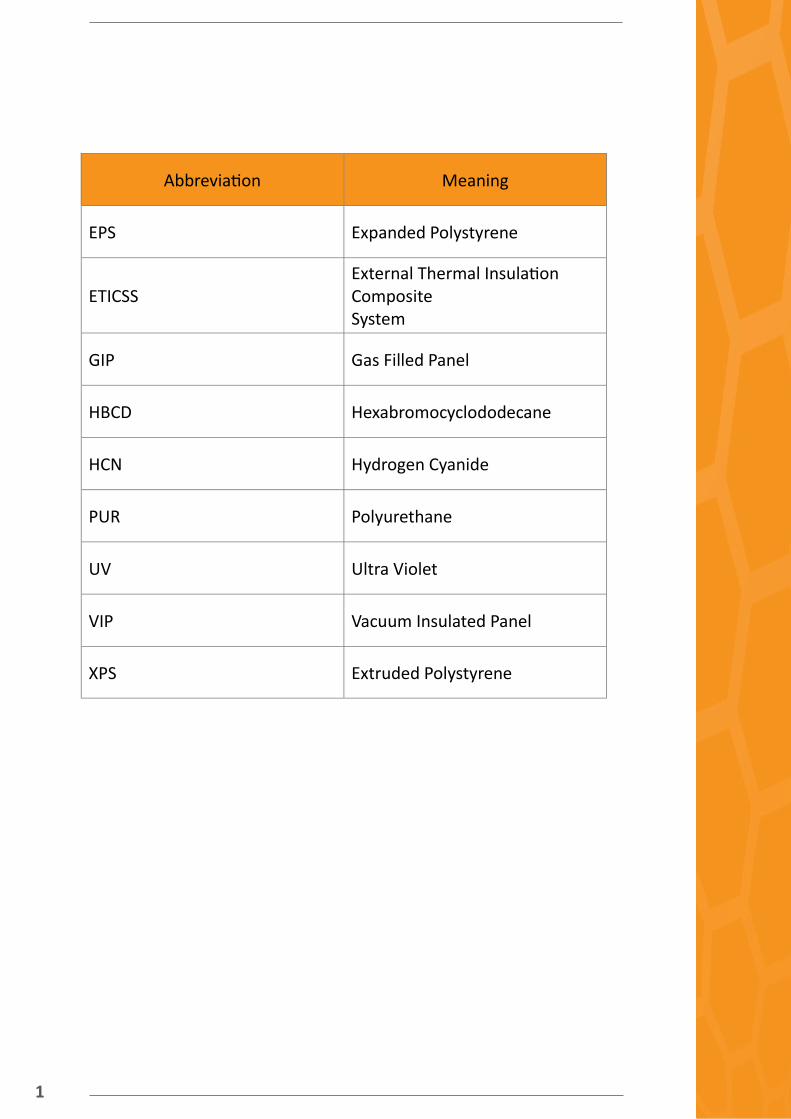
Abbreviations ..................................................................................................... 1
1. Introduction ................................................................................................... 2
2. Technical requirements .................................................................................. 3
2.1. Implementation ...................................................................................... 3
2.2. Durability ................................................................................................ 3
2.3. Manufacturing process ........................................................................... 4
3. Physical requirements .................................................................................... 4
3.1. Thermal insulation properties ................................................................. 5
3.1.1. Thermal conductivity and morphology of the pores............................. 5
3.1.1.1. Thermal conductivity requirements .................................................. 5
3.1.1.2. Traditional insulation materials ......................................................... 6
3.1.1.3. State-of-the-art insulation materials ................................................. 7
3.1.1.4. Nano-insulation materials ................................................................. 8
3.1.1.5. Values after ageing ............................................................................ 9
3.1.2. Density ............................................................................................... 10
3.1.3. Morphology ....................................................................................... 11
3.1.3.1. Current white EPS structure ............................................................ 11
3.1.3.2. Foam structure of EPS ..................................................................... 11
3.2. Flame retardancy .................................................................................. 12
3.2.1. Use of flame retardants...................................................................... 12
3.2.2. Flame retardant market and REACH ................................................... 13
3.2.3. Safety in case of fire: European classfication EN 13501 ..................... 13
3.2.4. National regulation in Europe ............................................................ 17
3.2.4.1. Spain ............................................................................................... 19
3.2.4.2. Germany ......................................................................................... 19
3.2.4.3. Sweden ........................................................................................... 20

3.2.5. Summary ........................................................................................... 21
4. Conclusion .................................................................................................... 22
5. Bibliography ................................................................................................. 24
Contents of Figures
Figure 1: Evolution of the needed thickness of the insulation material according to its thermal conductivity in order to reach a
U-value of 0.16 ................................................................................................... 6
Figure 2: Nano technologies are used to control the pore size in the thermal in-sulation context (Jelle 2010) ............................................................................... 8
Figure 3: Gas thermal conductivity versus pore dimension
(Jelle 2010) ......................................................................................................... 9
Figure 4: Form of an EPS foam cell .................................................................. 11
Figure 5: importance of use of fire retardants in case of fire (“SpecialChem” 13

Contents of Tables
Table 1: Characteristics of the main traditional insulation
materials ............................................................................................................ 7
Table 2: Densities of the traditional insulation material ................................. 10
Table 3: Examples of dimensions of a nano foam ........................................... 12
Table 4: Different classification from EN 13501-1 for construction
products ........................................................................................................... 14
Table 5: Smoke classification for construction products ................................. 15
Table 6: Flaming droplets/particles classification for construction
products ........................................................................................................... 15
Table 7: ETICSS fire classification according to test results .............................. 17
Table 8: Conversion table between national and European norms
concerning the reaction to fire of ETICSS (“SpecialChem”) ............................... 18
Table 9: Another conversion table for several European
countries .......................................................................................................... 18
Table 10: Conversion table between old (1990) Spanish legislation
and the new one (2002) implemented according to
EN 13501-1....................................................................................................... 19
Table 11: Classification of products according to DIN 4102 ............................. 20
Table 12: Implementation requirements ......................................................... 22
Table 13: Main physical requirements for the insulation product and the flame retardants ........................................................................................................ 22
1
Abbreviation Meaning
EPS Expanded Polystyrene
ETICSS
External Thermal Insulation Composite System
GIP Gas Filled Panel
HBCD Hexabromocyclododecane
HCN Hydrogen Cyanide
PUR Polyurethane
UV Ultra Violet
VIP Vacuum Insulated Panel
XPS Extruded Polystyrene

2
1. Introduction
The components of an ETICSS-System have to fulfill a number of requirements due to the
long period of use for thermally insulating buildings. They are continually exposed to
weathering and are put under a lot more stress than other building materials.
The durability of the thermal insulation material must be very high due to the
utilization phase lasting more than two decades. The thermal insulation properties must
remain constant or at least decrease only very slightly – the latter must be
considered during the planning by a factor. The mechanical properties too must fulfill the re-
quirements even after dynamic load during decades. Because of these high requirements only
two thermal insulation materials are commonly used, despite the efforts of other industries to
join the ETICSS market. The long experience with EPS and mineral wool incorporated in an ETICS
system helps to estimate the requirements for new insulation materials within ETICSS or better
insulation materials with less experience in ETICSS.
This document details the requirements the thermal insulation material has to fulfil.

3
2. Technical requirements
2.1. Implementation For the implementation, it has to be considered that the thermal insulation materials are easy to
use on site. This is not only a cost factor caused by a possible efficient installation but also in-
creases the acceptance of the installation workers for the new material. The thermal insulation
product has to be easy to handle for one single worker, meaning it has to be lightweight – under
3.5 kg for a board - and has a “one man board” size of <=500 x 1000 x thickness in mm. The di-
mensions of the board after gluing have to be very constant. The flatness may vary by +/- 3 mm,
the squareness, the length and the width by +/- 2 mm and the thickness by +/- 1 mm. It
should be easy for the construction workers to smooth the surface and to cut the
insulation product with saws and/or hot wires.
The non-reversible shrinkage between production and assembling may be 0.15 % maximum. If
the surface of the thermal insulation product is heated up by the sun, there must be no delami-
nation of the glued boards. No test method is available to validate this requirement though.
However, the delamination is only an issue for thermal insulation boards with a relatively low
thickness, as the tensions applied by the thermal expansion on the outer side cannot be compen-
sated so well. For the boards used today, this is not a problem anymore since boards with higher
thicknesses or lower thermal conduction are used.
For the easy implementation, it has to be assured that the thermal insulation product can be
stored outside. The UV-stability is not very relevant because the thermal insulation product
covered by the rendering. The insulation material is only exposed to UV light during the installa-
tion on site, meaning that the time span is too short for a degradation of the material.
In case of rain, the requirements are that the water uptake has to be low and will not change the
properties of the thermal insulation material. Standard EPS takes up approx. 0.2 kg/m² (tested by
24 h of partial immersion) water surpassing the requirement of a maximum uptake of 1 kg/m².
Such low water contents will not change the material properties and therefore the material can
be used without prior drying.
2.2. Durability The definition of a mechanical impact is not relevant, because this is tested for the
whole ETICSS except the adhesive. The dynamic load caused by wind, rain and
temperature differences is important and therefore defined. The shear strength has to be 50 kPa
or higher and the shear modulus 1000 kPa or higher. The pull through resistance of the anchors
has to be appropriate, and the tensile strength perpendicular to the surface has to be 100 kPa or
higher. These values are the result of a discussion regarding the development of standards in an
industrial union and are more demanding

4
than the values given in the official standards.
For the installed ETICSS, the weathering must not affect the properties of the thermal insulation
material. The water absorption has to be lower than 2%, and there is no advice for the water va-
pour permeability. The water permeability for EPS however is good with a µ- value of around 50,
meaning that the material dries very quickly in case of incidental water penetration. In case that
the thermal insulation product is implemented in the ETICSS, it has to stay stable in dimensions.
The change in the dimension caused by the influence of temperature and humidity may only be
2% or lower. The change in dimension during an unchanged standard climate may only vary by +/
- 0.2%.
2.3. Manufacturing process The basic raw materials have to be compatible with the foaming in the fabrication
process. The same equipment or a modified version of the equipment should be used. It would
not be acceptable to buy a completely new set of equipment. A pretesting of the materials has to
be performed on foaming and blocking equipment on a laboratory scale. No other concrete
properties of the raw material have to be defined.
The costs for the manufacturing process of the thermal insulation product are mainly given by
the raw material. The amount that can be charged for the product, however, is dependent on the
thermal conductivity and on the properties for the handling on site. The price of the thermal in-
sulation product and its thermal conductivity are not dependent in a linear behaviour. The
market price of a material with a lower thermal conductivity can be higher as one would expect
by the improved insulation alone since another benefit is the saving in space which is particularly
important in cities. An EPS material with improved thermal conductivity that maintains good
handling properties could therefore be sold at a higher price than the difference in thermal con-
ductivity would suggest.
3. Physical requirements The main physical requirement of an insulation material is to prevent the heat to pass through it.
The parameter which allows characterizing this physical phenomenon is the thermal conductivity
of the material (λ in W/(m.K)). The lower the thermal conductivity the better the heat insulation
of the material. In addition, the density and the morphology of the material are also important
requirements, which will also be studied in Chapter 3.1: Thermal insulation properties.
Buildings are exposed to risks of fire, the elements reaction to fire must also be assessed. The
reaction to fire of insulation material is important as it initiates or propagates the fire in the
building. The safety in case of fire of the insulation material is the subject of Chapter 3.2: Density
of this deliverable.

5
3.1 Thermal insulation properties Below, the thermal conductivity of insulation material is expressed as the sum of individual ther-
mal conductivities. This is followed by the requirements for insulating a building, the standard
values of traditional and then state-of-the-art insulation materials are discussed. Finally, the den-
sity and morphology are studied for both standard EPS and nano-foam EPS.
3.1.1. Thermal conductivity and morphology of the pores The thermal conductivity of an insulation material λ is the sum of the conductivity of different
components and physical properties of the material:
The solid state thermal conductivity, λsolid
The gas thermal conductivity, λgas
The radiation thermal conductivity, λrad
The convection thermal conductivity, λconv
The coupling thermal conductivity accounting for the second order effects between the pre-
viously stated thermal conductivities, λcoup
The leakage thermal conductivity. λleak
An efficient insulation material is characterized by a low thermal conductivity which is the sum of
all the previously mentioned thermal conductivities:
λinsulation = λsolid + λgas + λrad + λconv + λcoup + λleak
The thermal conductivity of the insulation is minimized by minimizing each of the individual ther-
mal conductivities of equation 1.
Conduction (in solid λsolid and gas λgas), convection (λconv) and radiation (λrad) are thus the physical
phenomena that shall be minimized inside the insulation material. All these thermal conductivi-
ties are dependent or driven by the temperature gradient inside the insulation material.
3.1.1.1. Thermal conductivity requirements The requirements for the thermal conductivity of an insulation material are different depending
on its use. Increasingly higher thermal resistance of external walls is required due to the thermal
regulations that are being implemented in Europe.
Climate, occupancy, and systems inside the building also influence the required thermal re-
sistance of external walls. When an overall thermal resistance is chosen, the thermal conductivity
of the insulation material impacts the thickness of the insulation needed to reach the required
thermal resistance as shown in Figure 1.
For this wall, an insulation thickness of 10 cm with a thermal conductivity of 20 mW/(m.K) allows
reaching a thermal resistance of 6.25 (m².K)/W. If the thermal conductivity of the insulation

6
material is 40 mW/(m.K) then a 20 cm thickness is needed to reach the same wall thermal re-
sistance.
Figure 1: Evolution of the needed thickness of the insulation material according to its thermal
conductivity in order to reach a U-value of 0.16
Very thick building envelopes are not desirable because they not only affect the available living
space of the building but also the transport volumes, the economy and sometimes the architec-
tures of the building. The implementation requirements described in the first part of the report
able also stated that the insulation panels must be lightweight in order to be handled by a single
man. It is therefore important to reduce the thickness of the insulation panel as much as possible
and to lower the thermal conductivity of the insulation material in order to do so.
A thermal conductivity around 20 mW/(m.K) allows having only 10 cm of insulation in order to
reach the good insulation value of 6.25 (m².K)/W for the wall, which is enough for new buildings
in Germany. Consequently, the value of 20 mW/(m.K) is a good objective for a new insulation
material.
3.1.1.2. Traditional insulation materials
A review of several traditional building insulation materials has been carried out in Jelle 10111,
the following table summarizes the information given in this article.
1 Jelle, Bjørn Petter. 2010. “Nanotechnology Applied in the Future Thermal Insulation Materials for Buildings - Tekna
Lecture.” https://www.tekna.no/ikbViewer/Content/807915/Nanotechnology%20Applied%20in%20the%20Future%
20Thermal%20Insulation%20Materials%20for%20Buildings%20-%20Tekna%20Lecture.pdf.

7
Table 1: characteristics of the main traditional insulation materials
(RH = Relative Humidity)
In Table 1, good on-site management means that the product can be perforated, cut and adjust-
ed without any loss of thermal resistance except for the thermal bridges created.
With a requirement of a wall thermal resistance of around 6, the thickness of a mineral wool, an
EPS or an XPS insulation material needed would be 20 cm or more. With cellulose insulation
material, the required thickness is 27 cm and 15 cm with PUR. Only PUR is able to reduce the
insulation thickness, though not drastically. Furthermore, PUR may raise health concerns in case
of a fire as it releases poisonous hydrogen cyanide (HCN) when burning.
None of the traditional materials described here allow for sufficient thermal resistance without
more than 10 cm of insulation. Only Polyurethane (PUR) comes close to this value but is danger-
ous for the residents in case of fire.
3.1.1.3. State-of-the-art insulation materials In the same article (Jelle 2011), state-of-the-art insulation materials are also reviewed. These
materials are the ones with the lowest thermal conductivity existing today
Insulation Type
Thermal conductivity range
On-site management
Comments
Mineral wool (Glass, rock wool)
30 – 40 mW/(m.k)
Good 55 mW/(m.k) with 10% RH
Expanded polystyrene (EPS)
30 – 40 mW/(m.k)
Good 54 mW/(m.k) with 10% RH
Extruded polystyrene (XPS)
30 – 40 mW/(m.k)
Good 44 mW/(m.k) with 10% RH
Cellulose 40 – 50 mW/(m.k)
Good 66 mW/(m.k) with 5% RH
Polyurethane (PUR)
20 – 30 mW/(m.k)
Good
46 mW/(m.k) with 10% RH + dangerous in case of fire

8
These state of the art materials offer thermal conductivity low enough to fulfill the
energy requirements of almost all external wall situations without significantly
increasing thickness. Yet, almost all of them have other disadvantages, such as great difficulty to
manage them on-site or a very high price. For these reasons the development of new insulation
technologies is important, and the nano technology approach developed in FoAM-BUILD is prom-
ising.
3.1.1.4. Nano-insulation materials Nano technologies are used in insulation materials in order to decrease the dimensions of the
pores containing the gas to dimensions under the 100 nm scale (Figure 2). For instance, if the gas
used in the insulation material is the air, reducing the dimension of the pores to under 40 nm
should allow reach value of gas thermal conductivity down to 4 mW/(m.K) in the pristine condi-
tions. The use of air is important because contrary to VIP or GIP there is no need to prevent air
penetration into the pore structure during the service life of the insulation system.
Figure 2: Nano technologies are used to control the pore size in the thermal insulation context
(Jelle 2010)
Insulation type
Thermal conductivity range
On-site manage-ment
Comments
Vacuum Insulation Panels (VIP)
3 – 5 mW/(m.K)
Difficult, puncturing of the panel => 20 mW/(m.K)
Good ageing, 8 mW/(m.K) after 100 years
Gas Filled Panels (GIP)
6 – 16 mW/(m.K)
Difficult, puncturing of the panel => 20 mW/(m.K)
Same structure than VIP but with gas instead of vacuum
Aerogels 13 mW/(m.K)
High compression strength, low ten-sile strength
Very high price 4 mW/(m.K) at 50 mbar

9
By using the Knudsen effect, the gas thermal conductivity λgas is decreased. The air-filled pores
dimension is decreased to under 50 nm, thus the mean free path of the gas molecules is larger
than the pore diameter. With this characteristic, a gas molecule situated inside the pore will hit
the pore wall and not another gas molecule.
Figure 3 shows the decrease of the conductivity with smaller gas pore diameter. With the air a
70 nm diameter is enough to have a gas thermal conductivity of under 5 mW/(m.K) under pris-
tine conditions. Such a small thermal conductivity is easier to reach when using other gases like
Krypton or Xenon, but then the insulation material needs to prevent air penetration in the pores
during its lifetime.
Figure 3: Gas thermal conductivity versus pore dimension (Jelle 2010)
Even if the impact of decreasing the pore diameters on the radiative part of thermal conductivity
λrad is not yet fully understood (Mulet et al. 2002), the low solid state lattice thermal conductivity
and the low gas thermal conductivity achieved by using nano technologies still dominate the ra-
diative part of thermal conductivity. Using nano technologies allows reducing the main thermal
contributions of equation
1. The very low gas thermal conductivity of 4 mW/(m.k) is solely possible in pristine condi-
tions but the total thermal conductivity value (see equation 1) taking into account all the
different contributions is not stated in Jelle 2011. Regarding the contribution of the radia-
tion thermal conductivity, the material has to be as impermeable as possible to infrared
radiation. This is necessary to reduce the radiation transfer in the panel. Another important
contribution to thermal conductivity is the convection thermal conductivity that is reduced
by using a close cell structure.
3.1.1.5. Values after ageing ETICSS systems being on the exterior part of the wall are not protected from the weather. Even if
the insulation part of the ETICSS is to some extent protected by the rendering, it is still under the
effects of weathering. The evolution of thermal conductivity with time due to ageing is an
important parameter when choosing the right insulation system.

10
The ageing of the insulation depends on the material type, the blowing agent, the temperature
and the thickness of the material but also on the other parts of the ETICSS like the facings. It is
difficult to correlate ageing with time for a given material. For EPS, the material is stored for 8
weeks at 60°C. After this period, no substantial change in the thermal conductivity will happen in
case the temperatures are not too high (up to 80°C). This means that the initial declared value of
the EPS already takes into account the ageing of the material. If the ageing of the material is not
taken into account when the declared thermal value is declared, a conversion factor is used (ISO
2007).
3.1.2. Density The density of the insulation material is an important characteristic of the material as it has an
impact on the thermal conductivity. It particularly influences the solid state thermal conductivity
and the radiation thermal conductivity of the insulation material. The higher the density, the
higher λsolid, but the lower λrad.
The density is also important for the mechanical properties of an insulation material such as the
compressive strength, the tensile strength and sheer strength.
Table 2: Densities of the traditional insulation material
The density of the ETICSS does not depend solely upon the density of the insulation
panel, but also on the other parts of the system. In order to be easy to implement, the ETICSS
shall be lightweight and therefore have a lower density than 7 kg/m² which corresponds to
around 70 kg/m3 for a 10cm board. ETICSS with rock
wool with a density up to 160 Kg/m3 are already being
sold, so the density of the EPS foam developed should
not be a problem for implementation on site. A desired
value for a nano-foam is 15 - 30 kg/m3.
Insulation Type Density
Mineral wool (Glass, rock wool)
45 - 160 kg/m3
Expanded polystyrene (EPS)
10 - 30 kg/m3
Extruded polystyrene (XPS)
28 - 45 kg/m3
Cellulose 30 - 55 kg/m3
Polyurethane (PUR)
30 kg/m3
The ETICSS shall
be lightweight and
have a lower density than
7kg/m2.
“ ”

11
3.1.3 Morphology
3.1.3.1. Current white EPS structure The white EPS is an example of EPS currently used in production. For this product, the beads are
round shaped but not perfectly spherical with a diameter of about 4.5 mm before blocking. The
cells in the bead have an average diameter of around 100 µm. After blocking, the beads are
pressed together, so that they are not round shaped anymore. However, the average diameter of
the cells more or less stays the same after blocking.
3.1.3.2. Foam structure of EPS EPS foam cells can be approximated by a pentagon dodecahedron as shown in
Figure 4:
Figure 4: Form of an EPS foam cell
The foaming properties of EPS are determined by its expandability, pressure
reduction time and surface quality. Optical and mechanical properties like the
stiffness of the foam are also important. All these properties are determined by the
homogeneity and size of the cells. When the cells become finer, the pressure
reduction time decreases drastically. A finer cell also means that the number of cells per volume
increases. If the number of cells is changed from 6 to 12 per mm, the pressure reduction time is
divided by two.
In order to obtain a homogeneous and fine cell structure nucleating agents are used. They are
added in the polymerization of expandable polystyrene or during extrusion. In the absence of
these nucleating agents, cells of different sizes are formed, breaking the homogeneity of the
foam. The dimension of nucleating agents should be less or equal to the cell wall thickness so it
should be a nano-sized material or an endothermic blowing agent.
polyethylene or polyolefin waxes
paraffins and FischerTropsch waxes
in general unbranched, nonpolar, i.e. unmodified, polyethylene waxes
Zinc stearat
polyisobutylene (i.e. patent US 3 929 686)

12
anorganic particles (Aerosil etc.) (patent EP 0 353 701)
dentritic polymers (i.e. patent EP 0 680 498)
Endothermic blowing agents (i.e. Hecofoam / www.hecoplast.de)
An example of dimensions of nano foam is shown in Table 3.
Table 3: Examples of dimensions of a nano foam
3.2. Flame retardancy The reaction to fire of the whole ETICSS is tested - not only of the EPS material alone - in ETAG
004 and EN 13501. Each country has its own requirements concerning the reaction to fire of
ETICSS. Often, the national requirements can be translated into the classification of EN 13501. As
every European country has a different legislation, the requirements of the three studied coun-
tries legislation (Spain, Germany and Sweden) will be exemplarily described below.
One of the main insulation materials used in ETICSS is EPS. Flame retardants like hexabromocy-
clododecane (HBCD) are added to EPS in order to improve its reaction to fire and obtain a better
classification according to EN 13501. HBCD was classified very toxic to aquatic organisms by the
European Chemicals Agency (ECA) and will therefore be prohibited by the EU starting from 21st
August 2015.
3.2.1. Use of flame retardants Flame retardants are not used for every type of insulation material, for instance, rock wool does
not need any added flame retardants in the material because it already has a very low reaction
to fire. Flame retardants are used with polymers though, as they initiate or propagate fires. Being
organic compounds, polymers decompose to volatile combustible products when they are ex-
posed to heat. The purpose of flame retardants is to slow down polymer combustion and degra-
dation, reduce smoke emission and avoid dripping. Thus, the escape time during a fire is in-
creased and the fire hazard decreased.
Cell size 200 nm
Edge length 215 nm
Surface area 0.95 μm²
Volume 0.08 μm3
Cells per m3 1.3 E+19
Area of all cells 1.3 E+7
Density of the nano foam
15 kg/m3
Thickness of cell walls 1.19 nm

13
Figure 5: importance of use of fire retardants in case of fire (“SpecialChem”)
3.2.2. Flame retardant market and REACH Flame retardants are used all over the world for a market of 5 billion USD with 2 million tons a
year. Among this market non-halogen products have already a large share, brominated flame
retardants which will be prohibited by REACH accounting for around 20% of the market. Bromin-
ated flame retardants are among the class of polybrominated diphenyl ethers (PBDE) which
contaminate the environment during their manufacturing but also during their life cycle and
destruction. As these flame retardants are very toxic for the environment, some of them were
prohibited by REACH in 2015. For instance, HBCD is on the “List of substances of very high con-
cern for authorisation”, Annex 14 of REACH.
However, halogen free flame retardants like metal-hydroxide (40% of the market) or phosphor
(15% of the market) have to be added in larger amounts to achieve the same flame retardancy as
halogenated flame retardant. This large amount of flame retardants decreases thermal and me-
chanical properties and leads to a poorer foamability.
There is a need to develop a new halogen-free flame retardant for thermoplastic foam. The
developed flame retardant should allow polymer based ETICSS to pass the requirements of all
European countries concerning the reaction to fire. The European classification is briefly de-
scribed in the following part along with the requirements of three representative countries:
Spain, Germany and Sweden.
3.2.3. Safety in case of fire: European classification EN 13501 The test methods of EN 13501 were developed by the CEN Technical Committee 127. Since 2001
all European countries have replaced their national classes by “Euroclass” or found an equivalent
between national and European classes. These test methods are valid for ETICSS and not solely
for the thermal insulation material. The requirements for the Safety of ETICSS in case of fire
come from the Council Directive 89/106/EEC. In the event of a fire, the ETICS system should:
limit the generation and spread of fire and smoke within the works,
limit the spread of fire to neighbouring construction works,
secure the occupants ways to leave the works,
The verification methods used to determine the performance of ETICSS in case of
14
take into account the safety of rescue teams.
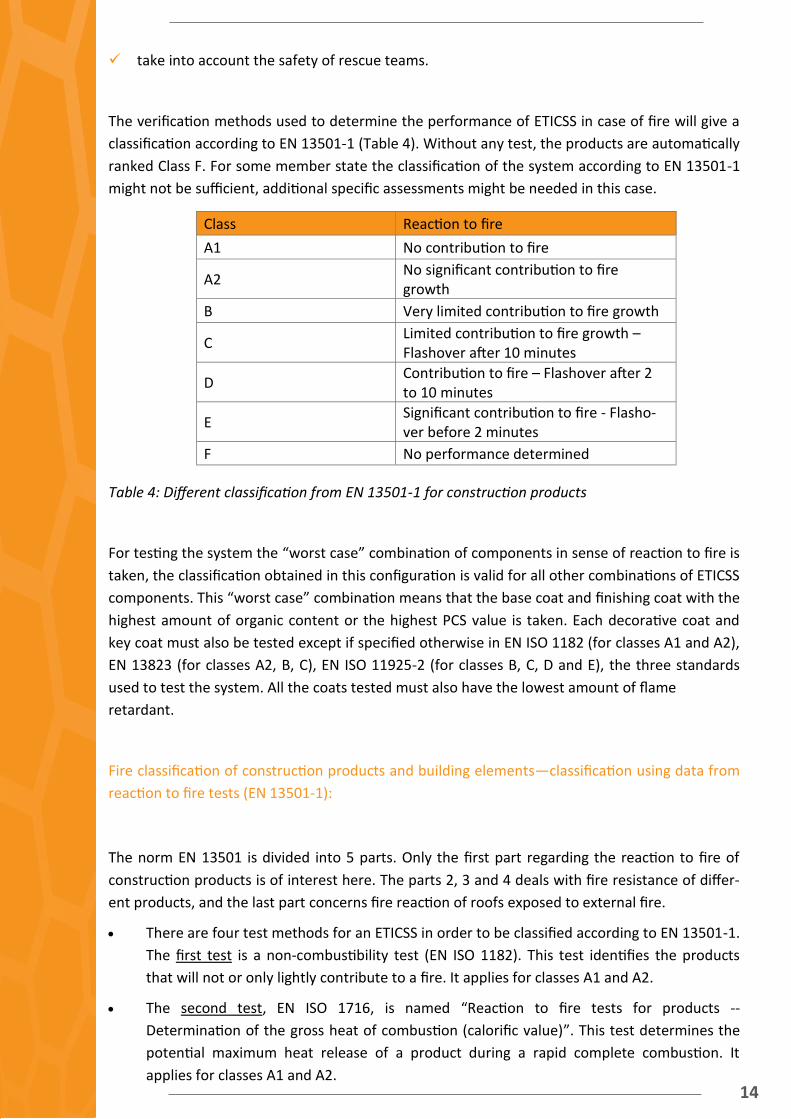
The verification methods used to determine the performance of ETICSS in case of fire will give a
classification according to EN 13501-1 (Table 4). Without any test, the products are automatically
ranked Class F. For some member state the classification of the system according to EN 13501-1
might not be sufficient, additional specific assessments might be needed in this case.
Table 4: Different classification from EN 13501-1 for construction products
For testing the system the “worst case” combination of components in sense of reaction to fire is
taken, the classification obtained in this configuration is valid for all other combinations of ETICSS
components. This “worst case” combination means that the base coat and finishing coat with the
highest amount of organic content or the highest PCS value is taken. Each decorative coat and
key coat must also be tested except if specified otherwise in EN ISO 1182 (for classes A1 and A2),
EN 13823 (for classes A2, B, C), EN ISO 11925-2 (for classes B, C, D and E), the three standards
used to test the system. All the coats tested must also have the lowest amount of flame
retardant.
Fire classification of construction products and building elements—classification using data from
reaction to fire tests (EN 13501-1):
The norm EN 13501 is divided into 5 parts. Only the first part regarding the reaction to fire of
construction products is of interest here. The parts 2, 3 and 4 deals with fire resistance of differ-
ent products, and the last part concerns fire reaction of roofs exposed to external fire.
There are four test methods for an ETICSS in order to be classified according to EN 13501-1.
The first test is a non-combustibility test (EN ISO 1182). This test identifies the products
that will not or only lightly contribute to a fire. It applies for classes A1 and A2.
The second test, EN ISO 1716, is named “Reaction to fire tests for products --
Determination of the gross heat of combustion (calorific value)”. This test determines the
potential maximum heat release of a product during a rapid complete combustion. It
applies for classes A1 and A2.
Class Reaction to fire
A1 No contribution to fire
A2 No significant contribution to fire growth
B Very limited contribution to fire growth
C Limited contribution to fire growth – Flashover after 10 minutes
D Contribution to fire – Flashover after 2 to 10 minutes
E Significant contribution to fire - Flasho-ver before 2 minutes
F No performance determined

15
The third test, the Single Burning Item test (SBI – EN 13823), evaluate the potential contri-
bution of an item to a fire, when exposed to thermal attack by a single burning item. It
applies for classes A2, B, C and D.
The last test concerns the ignitability of products subjected to direct impingement of
flames (EN ISO1925-2). It applies for classes B, C, D and E. All these tests aim at determining
values of different parameters in order to class the studied system under classes A1, A2, B,
C, D, E and F:
parameters ∆T and ∆m are determined with the norm EN ISO 1182 (non
combustibility test),
parameters higher calorific value (HCV) and the lower calorific value (LCV) are
determined with the norm EN ISO 1716 (determination of gross heat of
combustion)
parameters SMOGRA, TSP, LFS, FIGRA and THR are all determined in EN
13283
The class of a system is not determined with these parameters only, but also with observations
like the ignitability of the system according to EN ISO1925-2, smoke production and flaming
droplets/particles according to EN 13283. With the help of these parameter values and observa-
tions, the ETICS system is classified as shown in Table 5, Table 6 and Table 7.
Table 5: Smoke classification for construction products
Concerning the smoke production, the s3 class means that there are no limits to the production
of smoke. With an s2 class, the total production of smoke and its increasing rate of flow are lim-
ited. The s1 class implies stricter requirements than the s2 class.
Table 6: Flaming droplets/particles classification for construction products
The class d0 means that there are no flaming droplets and particles. The class d1 means that
there are no persistent flaming droplets and particles after an agreed period of time. The d2 im-
plies that there are no limits on these subjects.
These 7 classes, A1, A2, B, C, D, E, F allow to classify the tested product according to its reaction
s1 s2 s3
SMOGRA ≤ 30 m2/s2 and TSP600s ≤ 50 m2
SMOGRA ≤ 180 m2/s2 and TSP600s ≤ 200 m2
all other results
d0 d1 d2
No flaming droplets and particles after 600s
No persisting flaming drop-lets and particles for more than 10s
all other results
16
to fire. To resume, a product with an A class has less reaction to fire than a product with an class
and the F class means that the product`s reaction to fire was not tested.
A class F product means that no reaction to fire performance was assessed or than the prod-
uct cannot be classified in any other class
A class E product is able to resist for a short period to an attack of a small flame without any
substantial flame propagation.
A class D product satisfies the same criteria than a class E product but is able to resist for a
longer period to an attack of a small flame. This category of product is also able to limit or delay
the gross heat production under an attack of a single burning item (SBI)
A class C product satisfies the same criteria as a class D product but with additional stricter
requirements. This category of product is also able to limit the lateral propagation of a flame un-
der a thermal attack.
A class B product satisfies the same criteria as a class C product but with stricter require-
ments
A class A2 product satisfies the same requirement as a class B product regarding the norm
EN 13823. But in the case of a fully developed fire, this category of product does not significantly
contribute to the development of the fire
A class A1 product has the best capacity to resist to a fire, it does not contribute to any part
of a fully developed fire.

17
Table 7: ETICS fire classification according to test results
3.2.4. National regulation in Europe In the previous paragraph the European classification for the reaction to fire of ETIC systems was
presented. All the countries in Europe must now refer to this norm EN 13501. Some countries
still keep their previous national tests along with the mandatory European tests. A conversion
table to the European classification is shown in Table 8 and Table 9. It is important to note that
these conversion tables are only provided to promote a better understanding. The methodolo-
gies and measurements used in the national tests differ from those employed in the tests asso-
ciated with harmonized European tests. Products cannot assume a European class for reaction-to
-fire performance unless they have been tested using a European testing standard.
Class Test Method Criteria - parame-ters
Criteria - observations
A1
EN ISO 1182 and
∆T ≤ 30°C and ∆m ≤ 50% and no persistent fire (tf = 0)
-
EN ISO 1716 LCV ≤ 2 MJ/kg
A2
EN ISO 1182 or
∆T ≤ 50°C and ∆m ≤ 50% and tf ≤20s
- EN ISO 1716
and LCV ≤ 3 MJ/kg
EN 13832 FIGRA ≤ 120 W/s and THR600
≤ 7.5 Smoke production and
flaming droplets/particles
B
EN 13832 and FIGRA ≤ 120 W/s and THR600
≤ 7.5 Smoke production and
flaming particles EN ISO 1925-2: exposition
of 30 s
Fs ≤ 150mm in 60s
C
EN 13832 and FIGRA ≤ 250 W/s and THR600
≤ 15 Smoke production and
flaming droplets/particles EN ISO 1925-2: exposition
of 15 s
Fs ≤ 150mm in 60s
D
EN 13832 and FIGRA ≤ 750 W/s
Smoke production and flaming droplets/particles
EN ISO 1925-2: exposition
of 30 s
Fs ≤ 150mm in 60s
E EN ISO 1925-2: exposition
of 30 s
Fs ≤ 150mm in 60s
F No assessed performance

18
Table 8: Conversion table between national and European norms concerning the reaction to fire
of ETICSS (“SpecialChem”)
Table 9: Another conversion table for several European countries
The legislations of three of these countries are further studied in the following parts.
Contributing to fire propa-
gation
No contribu-tion
Quasi no-contribution
Very limited Limited Medium High
Euroclasses A1 A2 B C D E
AUT A A B1 B1 B2 B3
BEL A0 A1 A2 A3-A4 A3-A4 A4
FIN 1/I 1/I 1/I 1/II 1/- U
FRA M0 M0 M1 M2 M3 M4
GER A1 A2 B1 B2 B2 B3
IRE 0 0 0/1 1 3 4
ITA NC 0 1 2 3 4
NL NC 1 2 3 4 5
NO In1 In1 In1 In2 In2 U
PORT M0 M0 M2 M3 M4 M4
SK A B B B C2 C3
SWE I I I II III U
UK 0 0 0-1 1 3 4
USA NC - A B C -
Euroclass
In accordance with EN 13501-
1 + A1: 2009
UK
In accordance with Approved Docu-
ment B of the Building Regula-
tions
Germany
In accordance with Baurege-
listen, 26th March 2012
France
In accordance with Arrete du 21 Novembre
2002
Sweden
In accordance with Re-
gelssamling for byggande, BBR:
2012 and EN 13501-1
Italy
In accordance with Decreto del Ministero del’Interno 15 Marzo 2005
Netherlands
In accordance with
Bouwbesluit, 2012
A1
Non-combustible
A1
A1 (Non-
combustible prior to 1st Jan
2012)
Class 0 Non-
combustible
A2 Material of
limited com-bustibility
A2 M0 or M1
A2 (Material of limited com-
bustibility prior to 1st Jan 2012)
Class 1 or Class 2
B
Class 0 4 B1 M1
B (Class 1 surface lining prior to 1st Jan 2012)
Class 1 or Class 2
Class 1 or Class 2
C
Class 1 5 B1 M2
C Class 2 surface lining prior to 1st Jan 2012)
Class 2 or Class 3
Class 3
D
Class 3 B2 M3
D (Class 1 surface lining prior to 1st Jan 2012)
Class 3 Class 4
E B2 M4 E
F B3 F

19
3.2.4.1. Spain On 2nd July 2005 the publication of the (312/2005 RD): “classification of construction products
and the constructive elements based on their reaction and fire resistant properties" came into
force. This is a transposition of the European directive 89/106/EC in the Spanish legislative
framework. This Royal Decree (RD) gives legality to the implementation of the new European
classifications of resistance to fire and his essays.
This decree states that the tests used for the classification for the reaction to fire of construction
products are those of the norm EN 13238:2002, and the classification is specified according to
the norm EN 13501-1:2002. A conversion table is given in order to link the results of the Europe-
an tests with the previous national Spanish legislation UNE 23727:1990 (Table 10).
Table 10: Conversion table between old (1990) Spanish legislation and the new one (2002) imple-
mented according to EN 13501-1
Some construction elements of the building do not need to pass any tests in order to have a clas-
sification. Some of them automatically have a class A1 like mineral wools and lightweight aggre-
gates, comprising vermiculite, perlite and expanded clays. Most of these materials are currently
not used in ETICSS like concretes and cement. Other materials do not need tests to have their
class, but the class is assigned directly according to the material. Again, these materials are not
used in ETICS systems and are not insulation material, so the developed insulating material in
FoAM-BUILD must pass the tests of EN 13501-1 in order to be sold in Spain.
3.2.4.2. Germany The reaction to fire in Germany was traditionally classified at the material level. That is why the
national requirements are still used in parallel with the European requirements set with the Eu-
roclass system. In order to be commercialized on the German market, an insulation product must
be certificate with a “U-mark” that guarantees the compliance of the product with the old na-
tional fire safety requirements.
The German test standard for fire testing of insulation products like EPS is DIN 4102. Among the
several parts of this standard, part 1 and 15/16 are of particular interest for insulation products.
the mean residual length of the specimen are measured. If the smoke gas temperature is under
Classes according to Span-ish
UNE 23727:1990
Classes according to Euro-pean
EN 13501-1:2002
For thermal insulation products
M0 A1 to A2-s1,d0
M1 B-s3,d0
M2 C-s3,d0
M3 D-s3,d0
20
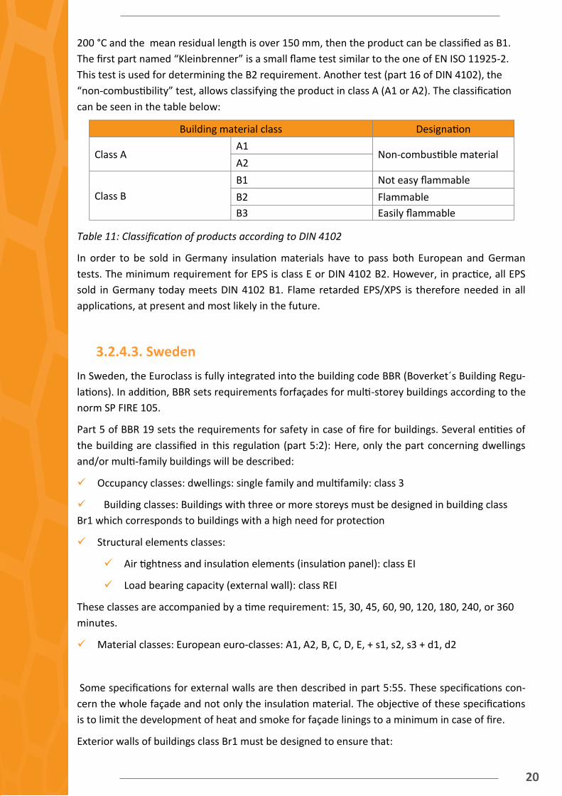
200 °C and the mean residual length is over 150 mm, then the product can be classified as B1.
The first part named “Kleinbrenner” is a small flame test similar to the one of EN ISO 11925-2.
This test is used for determining the B2 requirement. Another test (part 16 of DIN 4102), the
“non-combustibility” test, allows classifying the product in class A (A1 or A2). The classification
can be seen in the table below:
Table 11: Classification of products according to DIN 4102
In order to be sold in Germany insulation materials have to pass both European and German
tests. The minimum requirement for EPS is class E or DIN 4102 B2. However, in practice, all EPS
sold in Germany today meets DIN 4102 B1. Flame retarded EPS/XPS is therefore needed in all
applications, at present and most likely in the future.
3.2.4.3. Sweden In Sweden, the Euroclass is fully integrated into the building code BBR (Boverket´s Building Regu-
lations). In addition, BBR sets requirements forfaçades for multi-storey buildings according to the
norm SP FIRE 105.
Part 5 of BBR 19 sets the requirements for safety in case of fire for buildings. Several entities of
the building are classified in this regulation (part 5:2): Here, only the part concerning dwellings
and/or multi-family buildings will be described:
Occupancy classes: dwellings: single family and multifamily: class 3
Building classes: Buildings with three or more storeys must be designed in building class
Br1 which corresponds to buildings with a high need for protection
Structural elements classes:
Air tightness and insulation elements (insulation panel): class EI
Load bearing capacity (external wall): class REI
These classes are accompanied by a time requirement: 15, 30, 45, 60, 90, 120, 180, 240, or 360
minutes.
Material classes: European euro-classes: A1, A2, B, C, D, E, + s1, s2, s3 + d1, d2
Some specifications for external walls are then described in part 5:55. These specifications con-
cern the whole façade and not only the insulation material. The objective of these specifications
is to limit the development of heat and smoke for façade linings to a minimum in case of fire.
Exterior walls of buildings class Br1 must be designed to ensure that:
Building material class Designation
Class A A1
Non-combustible material A2
Class B
B1 Not easy flammable
B2 Flammable
B3 Easily flammable
21
1- the separation function is maintained between fire compartments,
2- the fire spread inside the wall is limited,
3- the risk of fire spread along the façade surface is limited,
4- the risk of injury due to parts falling from the exterior wall is limited.
Each of these 4 points implies a different requirement:
Point 1 is valid if the wall complies with EN 13501-2 with fire inside affect as specified in
chapter 4.2. (post flash-over fire). This is characterized by the following equation:
T = 345 log10(8t + 1) + 20
where
t is the time since the beginning of the test, [min]
T is the oven temperature. [°C]
This equation corresponds to the model of a fire fully developed in an oven.
Point 2 is valid if the wall contains only materials of at least class A2-s1, d0
Point 3 is valid if the wall is design in at least class A2-s1, d0
Point 4 is valid if the exterior walls are design to limit the risk of falling structural elements
such as broken glass, small bits of plaster and the like.
If the wall passes the test SP FIRE 105 issue 5 with:
no major parts of the façade that falls down,
fire spread on the surface finish and inside the wall is limited to the bottom edge of the win-
dow two floors above the fire room,
no exterior flames occur which could ignite the eaves located above the window two floors
above the fire room, then it meets points 1, 2, 3 and 4.
3.2.5. Summary Even if each country in Europe still has the possibility to have their own national regulation, all of
them must also follow the requirements of EN 13501. This norm defines the safety tests in case
of fire of building construction elements. Several classes from A1 (no contribution to fire) to E
(significant contribution to fire) and F (no performance determined) are available to assess the
performance of the material with regard to its fire resistance.
In order to improve the fire resistance performances of insulation material like EPS, flame retard-
ants were added to the matrial. With the new REACH regulation, some of these flame retardants
are prohibited, like HBCD. Other non-halogenated flame retardants exist but have to be added in
larger amounts to achieve the same flame retardancy as halogenated flame retardants. The large
amount of flame retardants decreases thermal and mechanical properties and leads to worse
foamability.

22
4. Conclusion In order to assure a sufficient market penetration for a new insulation material, several require-
ments must be met for the European market. Part of these requirements are technical and are
set to assure a good acceptance of the new material by the buyers and the workers on site.
The thermal insulation material developed within FoAM-BUILD will be easy to use on site, to pro-
duce, stock and transport. Several technical requirements were developed in this report to fulfill
these objectives as shown in the following table.
Table 12: Implementation requirements
Other requirements for a new insulation material to be part of an ETICSS are of physical nature,
namely the thermal performance and ability to prevent the spread of a fire. The main physical
requirements for the insulation system as reviewed in this deliverable are stated in Table 13.
Table 13: Main physical requirements for the insulation product and the flame retardants
A low thermal conductivity for EPS implies reducing the cell size under 1 μm in order to benefit
from the Knudsen effect which decreases the contribution of the gas (air) in the total thermal
conductivity of the insulation material. A thermal conductivity under 25 mW/(m.K) would allow
keeping reasonable sizes for insulation board (see Figure 1).
Parameters Requirements
“One man board” size <500 (width) x 1000 (height) in mm
“One man board” weight < 3,5 kg
Dimensions stability Flatness ± mm
squareness, length, width and thickness ±2 mm
thickness ± 1 mm
Possibility of cutting Easy without special equipment
Non reversible shrinkage between produc-tion and assembly in site
< 0,15 %
Gluing durability no delamination of the glued boards when heated
Outside storing possible weather conditions
Water update < 1 kg/m2 (0,2 kg/m2 for standard EPS)
Insulation product
Thermal conductivity λ < 25 mW/(m.K)
Morphology Cell size < 1 μm
Density d < 160 kg/m3
Flame retardant
REACH Non-brominated flame retard-ants
d < 160 kg/m3
EN 13501 class E or better
23
The reaction to fire of the insulation material should be good enough to have a class E of EN
13501 or better. This is mainly possible by adding a flame retardant in the EPS, but some flame
retardants, like HBCD will soon be prohibited by REACH (2015). Developing a flame retardant
allowing a class E EPS without decreasing the thermal insulation properties of the material is one
of the objectives of the FoAM-BUILD project.

24
5. Bibliography
312/2005 RD. “Classification of Construction Products and the Constructive
Elements Based on Their Reaction and Fire Resistant Properties.”
http://www.boe.es/boe/dias/2005/04/02/pdfs/A11318-11348.pdf.
Jelle, Bjørn Petter. 2010. “Nanotechnology Applied in the Future Thermal Insulation
Materials for Buildings - Tekna Lecture.”
https://www.tekna.no/ikbViewer/Content/807915/Nanotechnology%20Applied
%20in%20the%20Future%20Thermal%20Insulation%20Materials%20for%20
Buildings%20-%20Tekna%20Lecture.pdf.
———. 2011. “Traditional, State-of-the-Art and Future Thermal Building Insulation
Materials and Solutions – Properties, Requirements and Possibilities.” Energy
and Buildings 43 (10): 2549–63. doi:10.1016/j.enbuild.2011.05.015.
Mulet, Jean-Philippe, Karl Joulain, Rémi Carminati, and Jean-Jacques Greffet. 2002.
“Enhanced Radiative Heat Transfer at Nanometric Distances.” Microscale
Thermophysical Engineering 6 (3): 209–22. doi:10.1080/10893950290053321.
“SpecialChem.” http://www.specialchem4polymers.com/tc/flame
retardants/index.aspx?id=9302.