Embed Size (px)
Citation preview
Request for Proposal
Request for Proposal for “Civil & Interior /Electrical/HVAC & Plumbing Works for office space for WDRA on 4th floor at NCUI 3, Siri Institutional area, August Kranti Marg, Hauz Khas, New Delhi-16. Broadcast Engineering Consultants India Ltd. (BECIL) invites sealed tenders on two bid basis for setting up of infrastructure facilities for Warehousing Development and Regulatory Authority, Warehousing Bhawan, 4/1, Institutional Area, August Kranti Marg, Hauz Khas, New Delhi:- i) Issue of RFP notification : 19th July 2016 ii) Pre-bid Meeting : 27th July 2016 at 14:00 hours ii) Submission of proposals : 12th August 2016 till 12:00 Hrs iv) Opening of technical bids : 12th August 2016 at 14:30hrs v) Opening of financial bids : Shall be informed later. BECIL reserves the right to amend the RFP tentative schedule and critical dates. Tender document can be downloaded from the site www.becil.com or can be obtained from the Corporate Office at C-56-A/17, Sector -62, Noida 201307, Uttar Pradesh on payment of Rs. 2,000/- in form of Demand draft in favour of “Broadcast Engineering Consultants India Limited and payable at New Delhi”.
REQUEST FOR PROPOSAL (RFP)
Civil & Interior /Electrical/HVAC & Plumbing Works
For WDRA on 4th floor at NCUI 3, Siri Institutional area, August Kranti Marg, Hauz Khas,
New Delhi-16.
RFP No. BECIL/WDRA/Civil & Interior /Electrical/HVAC & Plumbing Works/ 2016-17 Dated: 19th July 2016
Broadcast Engineering Consultants India Limited
(A Government of India Enterprise) (A Mini Ratna Company)
Head Office: 14-B Ring Road, IP Estate, New Delhi- 110002
Tel: 011 23378823 Fax: 011 23379885
Corporate Office: BECIL BHAWAN, C-56-A/17, Sector-62, Noida-201 301
Tel: 0120 4177850 Fax: 0120 4177879
E-mail: [email protected] Web: www.becil.com
TABLE OF CONTENTS
SECTION I. GENERAL INFORMATION & INSTRUCTIONS TO BIDDERS
A. RFP Schedule and Critical Dates
B. Intent of the Request for Proposal
C. Procedure Terms and General Conditions
D. Eligibility Criteria
E. Commercial Terms & Conditions
1. Earnest Money Deposit
2. Prices
3. Payment Terms
4. Consignee
5. Packing
6. Invoice
7. Delivery Schedule & Commissioning Period
8. Performance Bank Guarantee
9. Guarantee / Warranty
10. Late Delivery Clause
11. Penalty Clause
12. Taxes
13. Compliance Statement
F. Proposal Response Format
G. Method of Evaluation and Award
H. Works Execution
I. BECIL Obligation
SECTION-II. BILL OF MATERIAL
1. CIVIL & INTERIOR WORK
2. ELECTRICAL WORK
3. HVAC
4. PLUMBING
SECTION III ENCLOSURES
A. FORMS
B. DRAWINGS (LAYOUT)
C. CHECKLIST
SECTION I
GENERAL INFORMATION & INSTRUCTIONS TO BIDDERS
CONTENTS
A. RFP SCHEDULE AND CRITICAL DATES
B. INTENT OF THE REQUEST FOR PROPOSAL
C. PROCEDURE FOR SUBMISSION OF BIDS AND TERMS AND CONDITION
D. ELIGIBILITY CRITERIA
E. COMMERCIAL TERMS AND CONDITIONS
F. PROPOSAL RESPONSE FORMAT
G. METHOD OF EVALUATION AND AWARD
H. WORKS EXECUTION
I. BECIL OBLIGATION
A. RFP SCHEDULE AND CRITICAL DATES
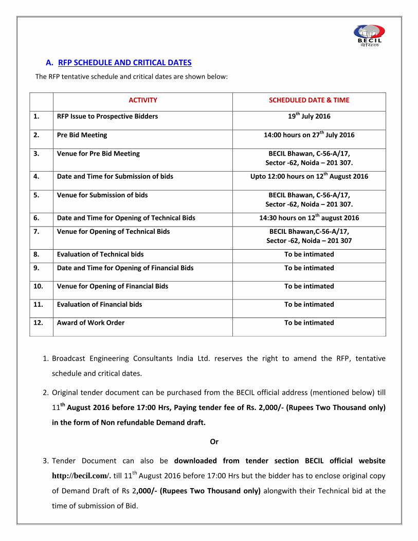
The RFP tentative schedule and critical dates are shown below:
1. Broadcast Engineering Consultants India Ltd. reserves the right to amend the RFP, tentative
schedule and critical dates.
2. Original tender document can be purchased from the BECIL official address (mentioned below) till
11th August 2016 before 17:00 Hrs, Paying tender fee of Rs. 2,000/- (Rupees Two Thousand only)
in the form of Non refundable Demand draft.
Or
3. Tender Document can also be downloaded from tender section BECIL official website
http://becil.com/. till 11th August 2016 before 17:00 Hrs but the bidder has to enclose original copy
of Demand Draft of Rs 2,000/- (Rupees Two Thousand only) alongwith their Technical bid at the
time of submission of Bid.
ACTIVITY SCHEDULED DATE & TIME
1. RFP Issue to Prospective Bidders 19th July 2016
2. Pre Bid Meeting 14:00 hours on 27th July 2016
3. Venue for Pre Bid Meeting BECIL Bhawan, C-56-A/17, Sector -62, Noida – 201 307.
4. Date and Time for Submission of bids Upto 12:00 hours on 12th August 2016
5. Venue for Submission of bids BECIL Bhawan, C-56-A/17, Sector -62, Noida – 201 307.
6. Date and Time for Opening of Technical Bids 14:30 hours on 12th august 2016
7. Venue for Opening of Technical Bids BECIL Bhawan,C-56-A/17, Sector -62, Noida – 201 307
8. Evaluation of Technical bids To be intimated
9. Date and Time for Opening of Financial Bids To be intimated
10. Venue for Opening of Financial Bids To be intimated
11. Evaluation of Financial bids To be intimated
12. Award of Work Order To be intimated
4. Demand Draft should be in favour of “Broadcast Engineering Consultants India Limited” payable at
New Delhi.
5. No tender document will be issued after the last date as mentioned above.
6. Office Address is as below:
BECIL BHAWAN,
C-56- A/17, Sector -62,
Noida 201 307
Tel. No. 0120 – 4177850
B. INTENT OF THE REQUEST FOR PROPOSAL
Broadcast Engineering Consultants India Limited has been engaged for setting up of office space for
WDRA on 4th floor at NCUI 3, Siri Institutional area, August Kranti Marg, Hauz Khas, New Delhi-16.
The space given for proposed setup need civil modifications for the strengthening of the structure and
conversion of the space for setting of office space and related services monitoring centre set up so that
the facility can be created in a well designed area.
The intent of this RFP is to make the designated space for WDRA on 4th floor at NCUI 3, Siri Institutional
area, August Kranti Marg, Hauz Khas, New Delhi-16. The Site modification work includes Civil &
Interior/Electrical/HVAC & Plumbing to suit the needs of WDRA. Interested bidders may visit the site.
C. PROCEDURE TERMS AND CONDITIONS
1. The proposal is to be submitted in TWO BID SYSTEM with Separate Technical and Financial bid under
separated sealed covers.
2. TWO BID SYSTEM
All bidders are required to submit their offer in two covers as under:-
2.1 TechnicalBid should contain the following:-
(i) Tender documents duly completed and signed without any financial quote.
(ii) The technical details of the models offered alongwith the supporting original technical literature,
Leaflets, Brochure etc. in duplicate.
2.2 Financial bid should contain the following:-
(i) Details of rate, taxes, duties, discount, if any, quoted by the bidder. These details should be
submitted on their letter head.
(ii) FOR terms, delivery period quoted.
Both the Technical and Financial bids should be sealed in separate envelop indicating “Technical Bid” &
“Financial Bid” and be kept in a third cover with properly sealed envelope.
2.3 This cover should also be superscribed with “BID FOR Civil & Interior /Electrical/HVAC & Plumbing Works
for WDRA on 4th floor at NCUI 3, Siri Institutional area, August Kranti Marg, Hauz Khas, New Delhi-16.”
against tender enquiry no. BECIL/WDRA/Civil & Interior /Electrical/HVAC & Plumbing Works/2016-17
dated: 19th July 2016, so as to reach us on or before 1200 Hrs on 12th August 2016.
2.4 The composite bid i.e. rate indicated in the Technical bid openly in tender is liable to be ignored. Only the
first cover i.e. Technical bid shall be opened on the date of tender opening.
The words “TECHNICAL BID” should be written clearly and prominently on the First cover alongwith tender
no. and date of opening. Similarly, the words “FINANCE BID” should be written clearly and prominently on
the second cover alongwith Tender No. and date of opening.
3. Bid Responses must be addressed to and submitted at the following address:
The Chairman & Managing Director
Broadcast Engineering Consultants India Ltd,
C-56 A/17, Sector -62, Noida 201 307
Tel: 0120-4177850
Fax: 0120-4177879
4. The Bids, both technical and the financial, should reach the office of BECIL, on the above address, not later
than 12:00 hours on 12th August 2016. Bids received beyond the specified date and time will be rejected. It
is the responsibility of the Bidder to confirm that the bids have been received on time & to the proper
place within the specified dates. Facsimile and electronic replies are not acceptable.
5. All bids are to remain valid for six months from the date of opening of Technical bid.

6. The bidder who will not pay/submit the EMD and Tender fee in the scheduled date & time, their bid will be
rejected, except NSIC valid certificate holding company/firm.
7. In case any of the information/declaration furnished by bidder is found to be wrong or any material
information is not disclosed by bidder while submitting bids, BECIL reserve the right to reject/cancel
corresponding bid of bidder and forfeit the Earnest Money Deposit (EMD).
8. Any Company is not allowed to participate in the RFP who has direct or indirect relationship with the
employee of BECIL/WDRA/CONSULATANT/ARCHITECT in any form, during designing or planning or
execution of the project.
9. In case work order has been awarded to any company/firm and later it is found by BECIL, that agency has
furnished wrong information/declaration or not disclosed any material information to BECIL while
submitting bid. BECIL reserve the right to cancel the work order awarded to Company/firm. Further BECIL
reserve the right to forfeit EMD and Bank Guarantee of the agency. The work will be done on the cost &
risk of the agency.
10. In case there is any material change in the financial status of bidder/ business of bidder , it should be
disclosed while submitting bid.
11. BECIL reserves the right to solicit additional information from Bidders to evaluate which bid best meets the
need of the Project. Additional information may include, but is not limited to, past performance records,
lists of available items of work will be done simultaneously with the project, on-site visit and evaluations
by BECIL personnel, or any other pertinent information. It will be vendor’s responsibility to check for
updated information on BECIL’s web site www.becil.com.
12. Additional questions should be submitted in writing to the RFP Coordinators addressed to
Mr. Ankur Saxena
(Manager) Broadcast Engineering Consultants India Ltd,
C-56 A/17, Sector -62, Noida 201 307 Tel: 0120-4177850 Fax: 0120-4177879
e-mail: [email protected]
Mr. Rajeev Sharma (Assistant Manager)
Broadcast Engineering Consultants India Ltd, C-56 A/17, Sector -62, Noida 201 307
Tel: 0120-4177850 Fax: 0120-4177879
e-mail: [email protected]
13. BECIL will make its decision based on the ability of the Bidder(s) to meet our specific needs, technical
expertise of the Bidder(s), delivery capabilities, customer references, past satisfactory performance
experience, is must besides cost.
14. BECIL reserves the right to waive off any deviations, accept the whole or part thereof or reject any or all
bids and to select the Bidder(s) which, in the sole opinion of the Project incharge, best meets the project’s
interest. BECIL also reserves the right to negotiate with potential bidders so that its best interest to fulfill
the need of project is served.
15. BECIL reserves the right to reject any and all proposals, to negotiate all terms of any agreement resulting
from this request for proposal, and to request additional information from vendors.
16. All information contained in this RFP, or provided in subsequent discussions or disclosures, is proprietary
and confidential. No information may be shared with any other organization, including potential sub-
contractors, without prior written consent of the RFP Coordinator.
17. BECIL reserves the right to either increase or decrease the quantity of any or all the items included in bill of
material which are estimated requirements and therefore open to variation.
18. BECIL reserves the right to alter/modify the scope of work mentioned in this RFP documents at any state of
the bidding process and contract.
18. The commercial bid shall clearly indicate the price to be charged without any qualification whatsoever and
should include all packing and forwarding, transportation, transit insurance, taxes, duties, fees, levies and
other charges as may be applicable in relation to the activities proposed to be carried out. All such charges
should be included in the rates quoted in the prescribed format.
19. The bidders may advise a list of their own recommended items and quote for these items separately which
in their opinion have been left out and shall be necessary for the successful implementation of the
overlays. A list of such items should be provided in the technical bid and rates of the same shall be
provided only in the commercial bid.
20. The bidders shall furnish activity-wise schedule in their bids. Time is the essence of the contract and no
time extension shall be granted under any circumstances. The successful bidder shall be required to abide
by the fix time lines.
21. The successful bidder shall keep BECIL informed of the progress on each activity on weekly basis. In case of
any delay in any particular activity, the recovery plan shall be evolved and given to BECIL for ensuring
completion of all the activities within the over all time schedule specified by BECIL. BECIL reserves the right
to terminate the contract at any stage of the work by giving 7 days notice if it is noticed that the delay
occurred in any of the activities covered under the contract cannot be made good and will affect the
overall work schedule. BECIL shall revoke the Performance Bank Guarantee of the bidder. The decision of
CMD, BECIL shall be final and binding.
24. BECIL reserves the right to monitor work execution progress and review it on day to day basis. The works
contractor will be fully transparent, responsive and demonstrate at all time that he is in position to
complete the work as per the specified time schedule.
25. The contractor shall be entirely responsible for the security of his personnel, material, plant and
equipment and the protection and security of the personnel, material, plant and equipment of any of his
sub-contractors. No extra cost shall be allowed to the contractor in the event to any damage occurring to
the contractors or any of his sub-contractors personnel, materials, plant and equipment whether stored
on site or offsite.
26. The bidders must have requisite qualified personnel for carrying out works of similar magnitude as
included in the tender.
27. The Contractor shall be responsible for any damage to the equipment /site occurred due to negligence of
contractor or subcontractor.
28. The contractor shall ensure that it has at all time a competent and qualified representative available at
site during the working period for the duration of the contract. Any direction given to contractor’s
representative shall be deemed to have been given to the contractor. Details on the nominated
contractor’s representative shall be included in the technical bid. In case the contractor proposes to
change the nominated representative or any other key personnel, the proposed change shall be
submitted to BECIL for approval.
29. In case Company goes into liquidation or change in business/management, it will be intimated to BECIL &
company will fulfill its commitment in case order is awarded to them.
30. Indemnification:
Contractor agrees to indemnify BECIL from any and all claims, demands, losses, cause of action, damage,
lawsuits, judgments, including attorneys’ fees and costs, arising out of or relating to the work of Contractor
including the works as got done by Contractor through Sub-Contractor(s),if so appointed by the
Contractor. BECIL shall have no role in engaging of sub-contractors by the Contractors and Contractor
alone shall be responsible to such Sub-Contractors.
31. Arbitration:
Any dispute or difference or claim arising out of or in relation to this contract, including the construction,
validity, performance or breach thereof, shall be settled or decided by arbitration to be conducted by
CMD, BECIL or by any other person to be nominated by CMD, BECIL. Arbitration shall be conducted as per
Arbitration & Conciliation Act, 1996.The seat of the arbitration shall be at New Delhi.
32. Jurisdiction
This Agreement shall be construed, interpreted and applied in accordance with, and shall be governed by,
the laws applicable in India. The courts at Delhi shall have the exclusive jurisdiction to entertain any matter
arising out of or in relation to this Agreement.
D. ELIGIBILITY CRITERIA
1. Bidder has to pay Tender fee(Non refundable) of Rs. 2,000/- (Rupees Two Thousand only) in the form of
Demand Draft in favour of Broadcast Engineering Consultants India Ltd. payable at New Delhi.
2. Bidder has to pay an EMD fee of Rs. 4,00,000/- (Rupees Four Lakh Only) should be paid only in form of
Demand Draft (No other mode of payment will be accepted) in favour of “Broadcast Engineering
Consultants India Ltd. Payable at New Delhi”. No interest is payable on EMD.
3. The bidder should be registered under Indian Company Act 1956. A copy of registration certificate should
be submitted.
4. The bidders should have successfully carried out atleast one or more similar projects i.e. Civil &
interior/Electrical/HVAC & Plumbing in last 3 financial year i.e. 2013-14, 2014-15 and 2015-16 of area of
9,000 sq feet or more in India. (Documentary proof such as copy of work order / completion certificate to
be submitted)
5. The bidders should have Minimum Turnover of INR One Crore for each 3 Financial Year (2012-13, 2013-14
and 2014-15) Copy of Audited Financial Statement (Annual Account) should be submitted for the
mentioned three years.
6. The Bidder should be Financially sound Company and should have earned Net Profit in each of the last
Three Financial Years i.e In F.Y. 2012-13, 2013-14 and 2014-15 .(Copy of Audited Financial Statement
(Annual Account) should be submitted for mentioned three years.
7. The bidder is required to submit following documents:*
a) Company Registration
b) Copy of PAN No.
c) Copy of TAN No.
d) Copy of Service Tax No.
e) Copy of TIN/VAT No.
f) Copy of EPF and ESI Registration Cetificate
*In case any document mentioned above is not submitted, the bid shall stand rejected.
8. The bidder should not have been barred or black-listed by any of the central govt.
departments/organizations, central/state PSUs. An undertaking with self-declaration certificate on a non
judicial stamp paper of Rs 100/- certified by Notary should be submitted along with the technical bid (as
given under heading Forms).
9. Bidder should submit self-declaration certificate for Total Responsibility Undertaking regarding project. (as
given under heading Forms)
10. The compliance statement including Bill of Material duly signed and stamped by OEM/Bidder on their letter
head should be submitted by bidder.
11. A separate point by point compliance statement duly signed and stamped by bidder in respect to all points
laid down in BOM and specifications for all the equipment/item(s)/works must be submitted.
12. Bidder have to submit signed copy of the tender document including all related amendment/corrigendum
in support of having been read, understood and complied with the requirements and terms and conditions
of the tender/RFP.
E. COMMERCIAL TERMS AND CONDITIONS
Each bidder is required to accept the following terms and conditions:-
1. Earnest MoneyDeposit : Each bidder is required to submit Earnest Money Deposit (EMD) of
Value Rs 4,00,000/-(Rupees Fourlakh only).EMD should be in the form
of Demand draft from scheduled bank in favor of “Broadcast
Engineering Consultants India Limited payable at New Delhi” and it will
not be accepted in any other form. Bid without EMD will not be
accepted. No interest is payable on EMD amount.
2. Prices : The Prices should be quoted in Indian Rupees only and prices should be
FOR site/ BECIL’s Stores at 14-B, Ring Road,I.P. Estate,New Delhi -
110002.
The prices should be quoted exclusive of taxes and all applicable taxes
should strictly be mentioned as per format given in Table 1 ofRFP
In case, taxes are not mentioned in Financial bid, prices shall be
considered inclusive of taxes.
3. Payment Terms for INR : 70% Paymentof total order value shall be made as per running bills
certified by Architect appointed by BECILafter delivery of material at site
(WDRA, New Delhi).
20%payment of total order value shall be made after satisfactory
completion of work.
10% payment of total order value shall be made against submission of
the PBGvalid till beyond 3 months from thedate of completion
ofwarranty/guarantee (as mentioned inclause 8 & 10 of Commercial
Terms and Conditions) in favor of Broadcast Engineering Consultants
India Limited payable at NEW DELHIafter completion of work.
4. Consignee : The material/equipment should be consigned to WDRA C/o Project
Manager, BECIL.
5. Packing : The material/equipment should be securely packed to withstand transit
hazards during different modes of transportation.
6. Invoice : All Invoices should be raised in the name of WARE HOUSING
DEVELOPMENT AUTHORITY (WDRA). NEW DELHI through Broadcast
Engineering Consultants India Limited.
7. Delivery schedule and
Commissioning
: All material unless otherwise stated in RFP shallbe delivered and
works executed within a period of 8 weeks from the date of release
ofWork Order.
8. Performance Bank Guarantee
: The successful bidder shall have to furnish aPerformance bank
guarantee (PBG) in favor of Broadcast Engineering Consultants India
Ltd,14-B, Ring Road IP Estate, New Delhi – 110002 for an amount equal
to 5% of order value, and valid till the period of warranty/guarantee,
within 15 days of release of Work order.
9. Guarantee/ Warranty
All equipment and works shallhave guarantee/warranty for the duration
of minimum one year and defects, if any, as reported shall be attended
to without any charges, whatsoever.
10. Late Delivery : In case of late delivery of item, the supplier shall be liable to pay penalty
@ 0.5 % of the item cost delivered late per week of delay or a part
thereof, upto a maximum amount of 5% of the delayed item value, after
which the order is liable to be cancelled.
11. Penalty Clause : In case the material/equipment supplied is not as per technical
specification mentioned in tender, the supplier will have to pay a
penalty @5% of total value of product/item.
This, however, does not absolve the tenderer from the supply of
required material/equipment as per Work Order.
12. Taxes : Taxes at source and Work Contract Taxes (WCT) will be deducted from
the invoice as applicable.
13. Compliance Statement A point by point full compliance statement in respect to all parameters
related to the concerned equipment/items from the respective principle
manufacturers should be submitted in the prescribed format given at
Table 1.
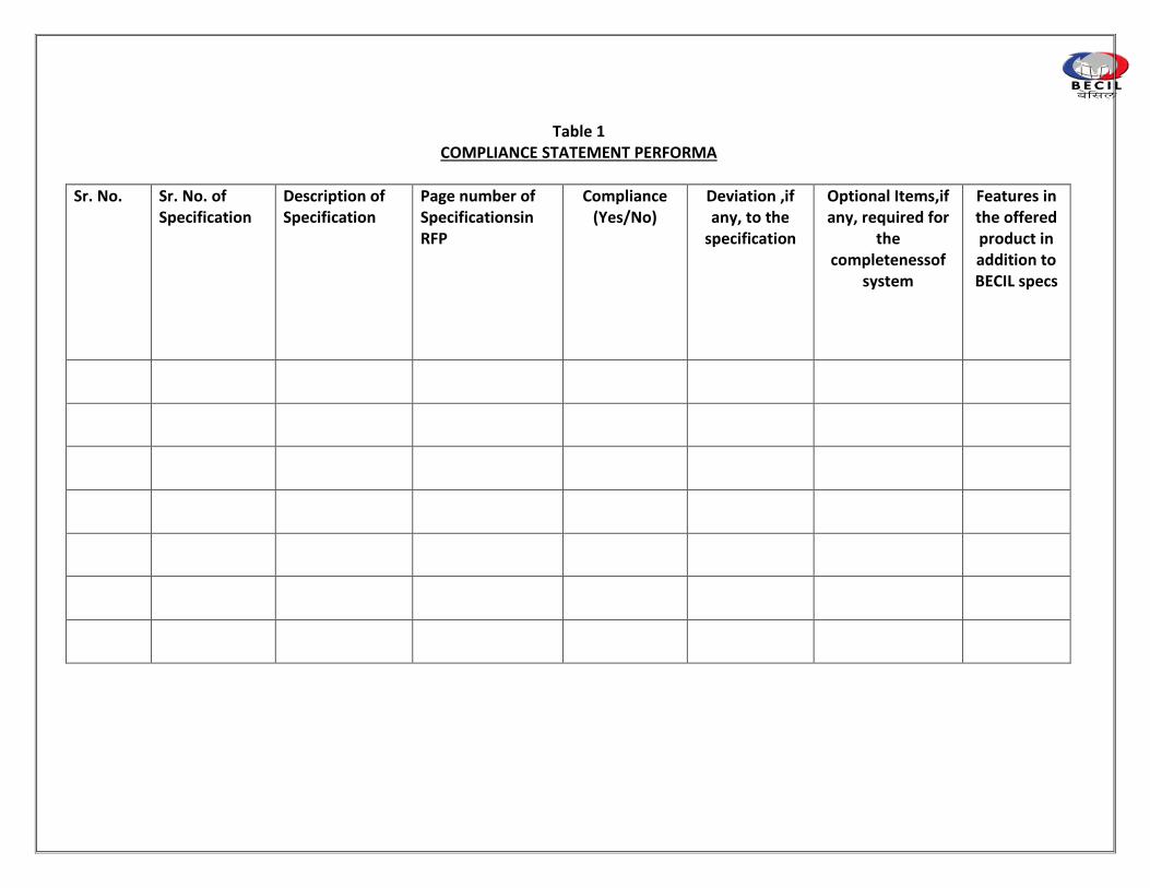
Table 1 COMPLIANCE STATEMENT PERFORMA
Sr. No. Sr. No. of Specification
Description of Specification
Page number of Specificationsin RFP
Compliance (Yes/No)
Deviation ,if any, to the
specification
Optional Items,if any, required for
the completenessof
system
Features in the offered product in addition to BECIL specs
F. PROPOSAL RESPONSE FORMAT
All the bidders are requested to use the same or similar format as given below while submitting the
commercial bids. The proposal must be submitted strictly in the following fashion as in Table 2.
1. The proposal shall be submitted in the same envelope at the same time, in two distinct parts: a
Technical Proposal and a commercial Proposal.
2. Proposals are to be prepared on standard 8-1/2” x 11” A4 size paper. Foldouts containing charts,
spreadsheets, and oversize exhibits are permissible. The pages should be placed in a binder with
tabs separating the sections of the proposal.Manuals and other reference documentation may be
bound separately. All responses, as well as any reference materials presented must be written in
English.
3. Proposals must respond to the RFP requirements by restating the number and text of the
requirement in sequence and writing the response immediately after the requirement statement.
4. Figures and tables must be numbered and referenced in the text by that number. They should be
placed as close to possible to the referencing text. Pages must be numbered consecutively within
each section of the proposal showing proposal section and page number.
5. Proposals shall be based only on the items contained in this RFP and its standard required
accessories. The RFP includes official response to pre-proposal conference questions, addenda, and
any other material published by the BECIL pursuant the RFP. The bidder is to disregard any previous
draft materials and any oral representations it may have received. All responses to the requirements
in Sections (list appropriate section) of this RFP must clearly state whether the proposal will satisfy
the referenced requirements, and the manner in which the requirement will be satisfied.
6. Pricing information shall appear only in the commercial bid and the technical bid shall contain
details of material offered and a compliance statement with reference to the bid document
highlighting any deviations.EMD as well as demand draft towards cost of tender document in case
downloaded from BECIL website shall be part of the technical bid.
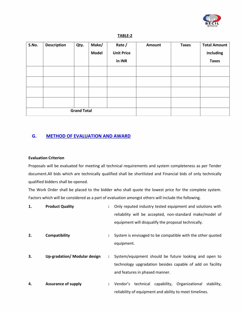
TABLE-2
G. METHOD OF EVALUATION AND AWARD
Evaluation Criterion
Proposals will be evaluated for meeting all technical requirements and system completeness as per Tender
document.All bids which are technically qualified shall be shortlisted and Financial bids of only technically
qualified bidders shall be opened.
The Work Order shall be placed to the bidder who shall quote the lowest price for the complete system.
Factors which will be considered as a part of evaluation amongst others will include the following.
1. Product Quality : Only reputed industry tested equipment and solutions with
reliability will be accepted, non-standard make/model of
equipment will disqualify the proposal technically.
2. Compatibility : System is envisaged to be compatible with the other quoted
equipment.
3. Up-gradation/ Modular design : System/equipment should be future looking and open to
technology upgradation besides capable of add on facility
and features in phased manner.
4. Assurance of supply : Vendor’s technical capability, Organizational stability,
reliability of equipment and ability to meet timelines.
S.No. Description Qty. Make/
Model
Rate /
Unit Price
in INR
Amount Taxes Total Amount
including
Taxes
Grand Total
5. Quality : Equipment stability, guaranteed uptime parameters, life of
equipment.
6. Service : After sales service, availability of spare parts/technical
support, warrantee offered.
7. Cost : Cost of the system as proposed and the apparent future
financial implications, AMC and Total cost of Ownership.
8. Integration
Experience
: Expertise and experience of the bidder in system / sub
system of integration of work of similar nature.
9. Delivery Schedule : Delivery timeline will be critical parameter for evaluation
and final decision.
10. Regulatory : Should meet the Regulatory compliance, Safety
requirements, Environmental objectives.
H. WORKS EXECUTION 1. All the works shall be executed in a professional manner, and in line with established ‘Good Practice’.
2. All internal woodwork shall be treated with anti termite. Timber used for framework shall be kiln
seasoned and should be free from shrinkage, warpage.
3. Provision to be made for additional supports and reinforcement that may be required for stability
and evenness.
4. Contractor to make provisions of all necessary scaffoldings to facilitate high level installations.
Contractor to form openings on partition for services and to seal gaps using silicon sealant.
5. Where the use of spring loaded auto closing hinges is specified, the same shall be installed strictly as
per manufacturer’s guidelines and relevant tools required for the same.
6. All drawings to be referred while quoting.
7. All woodwork and fabric shall be supplied with fire retardant treatment.
I. BECIL OBLIGATIONS
BECIL reserves the right to accept any bid, reject any or all bids and to annul the bidding process at
any time prior to the award of the contract without there by incurring any liability to the affected
bidder/bidders or any obligations to inform to the affected bidder/bidders of the grounds for BECIL’s
action.
SECTION II
BILL OF MATERIAL
1) CIVIL & INTERIOR WORK
2) ELECTRICAL WORK
3) HVAC
4) PLUMBING
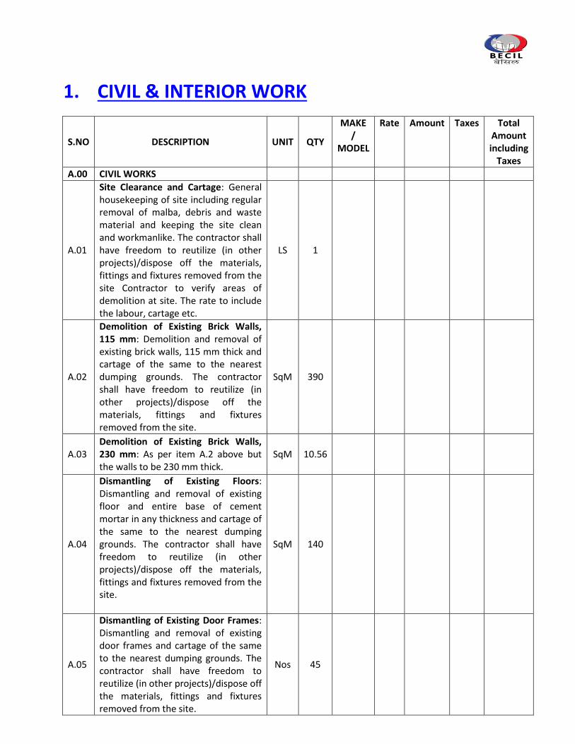
1. CIVIL & INTERIOR WORK
S.NO DESCRIPTION UNIT QTY
MAKE /
MODEL
Rate Amount Taxes Total Amount including
Taxes
A.00 CIVIL WORKS
A.01
Site Clearance and Cartage: General housekeeping of site including regular removal of malba, debris and waste material and keeping the site clean and workmanlike. The contractor shall have freedom to reutilize (in other projects)/dispose off the materials, fittings and fixtures removed from the site Contractor to verify areas of demolition at site. The rate to include the labour, cartage etc.
LS 1
A.02
Demolition of Existing Brick Walls, 115 mm: Demolition and removal of existing brick walls, 115 mm thick and cartage of the same to the nearest dumping grounds. The contractor shall have freedom to reutilize (in other projects)/dispose off the materials, fittings and fixtures removed from the site.
SqM 390
A.03 Demolition of Existing Brick Walls, 230 mm: As per item A.2 above but the walls to be 230 mm thick.
SqM 10.56
A.04
Dismantling of Existing Floors: Dismantling and removal of existing floor and entire base of cement mortar in any thickness and cartage of the same to the nearest dumping grounds. The contractor shall have freedom to reutilize (in other projects)/dispose off the materials, fittings and fixtures removed from the site.
SqM 140
A.05
Dismantling of Existing Door Frames: Dismantling and removal of existing door frames and cartage of the same to the nearest dumping grounds. The contractor shall have freedom to reutilize (in other projects)/dispose off the materials, fittings and fixtures removed from the site.
Nos 45
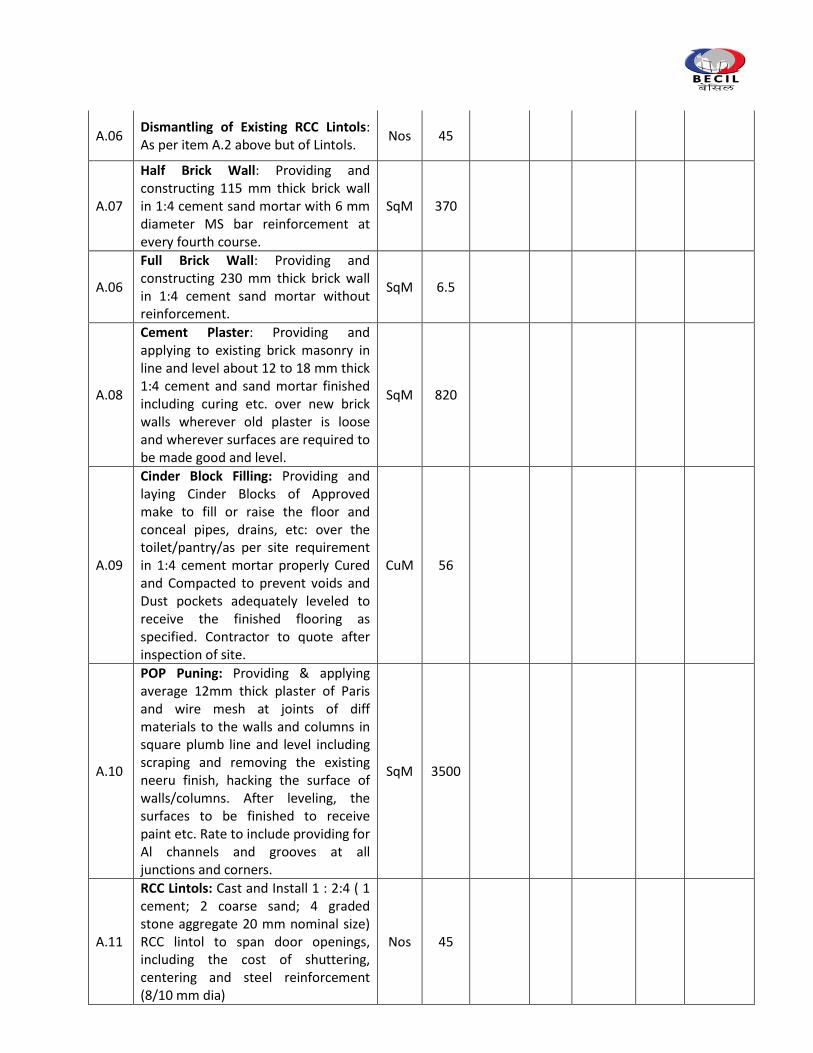
A.06 Dismantling of Existing RCC Lintols: As per item A.2 above but of Lintols.
Nos 45
A.07
Half Brick Wall: Providing and constructing 115 mm thick brick wall in 1:4 cement sand mortar with 6 mm diameter MS bar reinforcement at every fourth course.
SqM 370
A.06
Full Brick Wall: Providing and constructing 230 mm thick brick wall in 1:4 cement sand mortar without reinforcement.
SqM 6.5
A.08
Cement Plaster: Providing and applying to existing brick masonry in line and level about 12 to 18 mm thick 1:4 cement and sand mortar finished including curing etc. over new brick walls wherever old plaster is loose and wherever surfaces are required to be made good and level.
SqM 820
A.09
Cinder Block Filling: Providing and laying Cinder Blocks of Approved make to fill or raise the floor and conceal pipes, drains, etc: over the toilet/pantry/as per site requirement in 1:4 cement mortar properly Cured and Compacted to prevent voids and Dust pockets adequately leveled to receive the finished flooring as specified. Contractor to quote after inspection of site.
CuM 56
A.10
POP Puning: Providing & applying average 12mm thick plaster of Paris and wire mesh at joints of diff materials to the walls and columns in square plumb line and level including scraping and removing the existing neeru finish, hacking the surface of walls/columns. After leveling, the surfaces to be finished to receive paint etc. Rate to include providing for Al channels and grooves at all junctions and corners.
SqM 3500
A.11
RCC Lintols: Cast and Install 1 : 2:4 ( 1 cement; 2 coarse sand; 4 graded stone aggregate 20 mm nominal size) RCC lintol to span door openings, including the cost of shuttering, centering and steel reinforcement (8/10 mm dia)
Nos 45
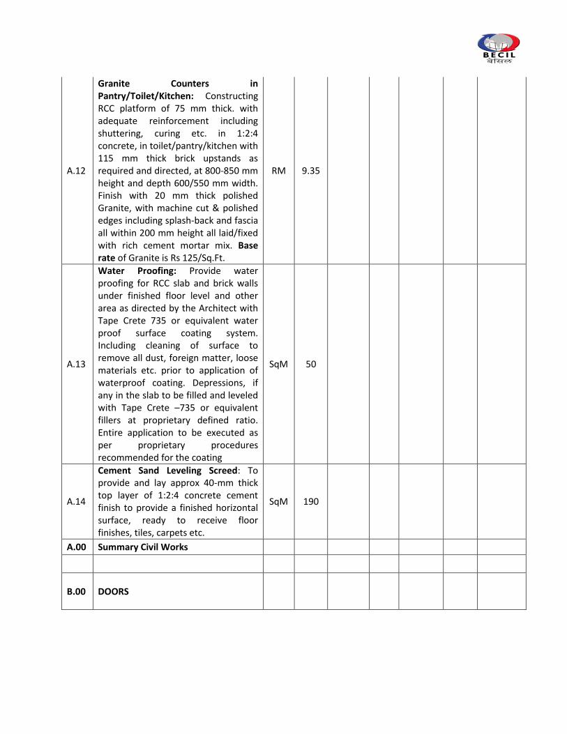
A.12
Granite Counters in Pantry/Toilet/Kitchen: Constructing RCC platform of 75 mm thick. with adequate reinforcement including shuttering, curing etc. in 1:2:4 concrete, in toilet/pantry/kitchen with 115 mm thick brick upstands as required and directed, at 800-850 mm height and depth 600/550 mm width. Finish with 20 mm thick polished Granite, with machine cut & polished edges including splash-back and fascia all within 200 mm height all laid/fixed with rich cement mortar mix. Base rate of Granite is Rs 125/Sq.Ft.
RM 9.35
A.13
Water Proofing: Provide water proofing for RCC slab and brick walls under finished floor level and other area as directed by the Architect with Tape Crete 735 or equivalent water proof surface coating system. Including cleaning of surface to remove all dust, foreign matter, loose materials etc. prior to application of waterproof coating. Depressions, if any in the slab to be filled and leveled with Tape Crete –735 or equivalent fillers at proprietary defined ratio. Entire application to be executed as per proprietary procedures recommended for the coating
SqM 50
A.14
Cement Sand Leveling Screed: To provide and lay approx 40-mm thick top layer of 1:2:4 concrete cement finish to provide a finished horizontal surface, ready to receive floor finishes, tiles, carpets etc.
SqM 190
A.00 Summary Civil Works
B.00 DOORS
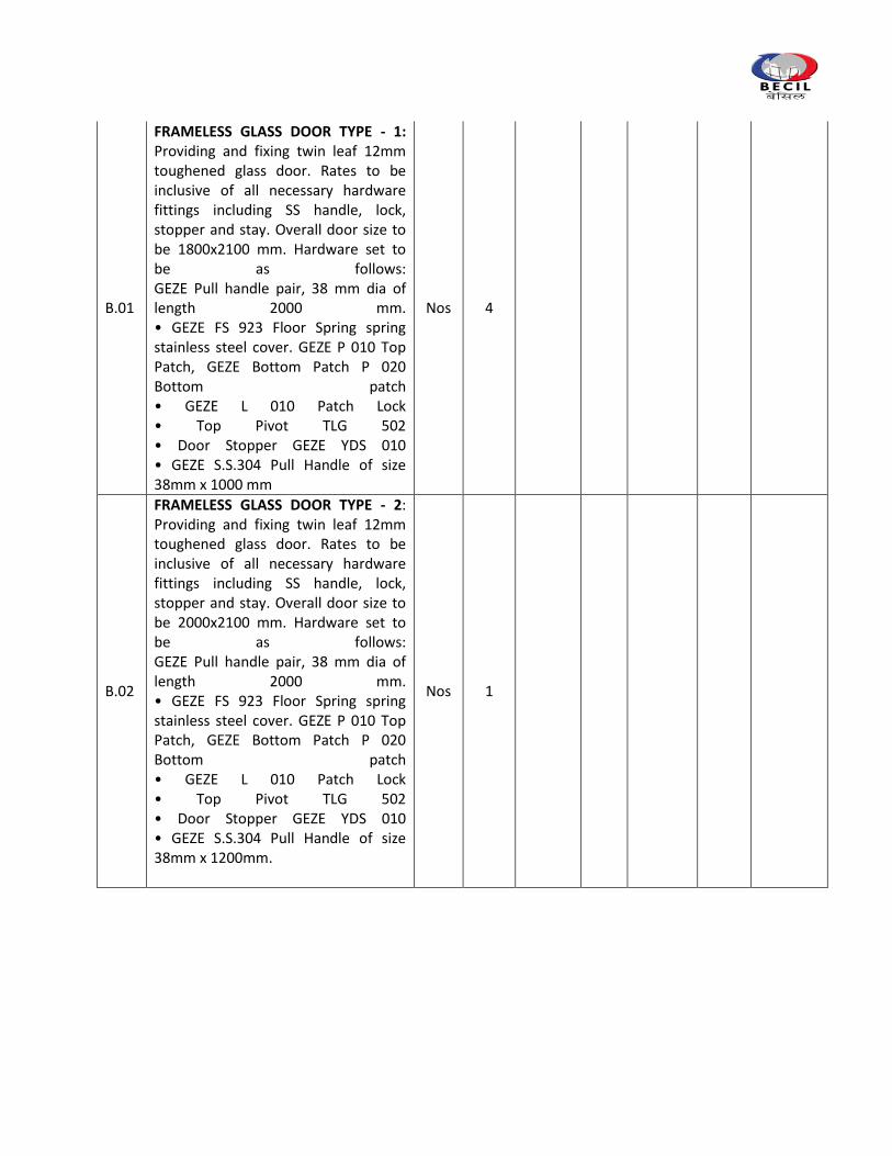
B.01
FRAMELESS GLASS DOOR TYPE - 1: Providing and fixing twin leaf 12mm toughened glass door. Rates to be inclusive of all necessary hardware fittings including SS handle, lock, stopper and stay. Overall door size to be 1800x2100 mm. Hardware set to be as follows: GEZE Pull handle pair, 38 mm dia of length 2000 mm. • GEZE FS 923 Floor Spring spring stainless steel cover. GEZE P 010 Top Patch, GEZE Bottom Patch P 020 Bottom patch • GEZE L 010 Patch Lock • Top Pivot TLG 502 • Door Stopper GEZE YDS 010 • GEZE S.S.304 Pull Handle of size 38mm x 1000 mm
Nos 4
B.02
FRAMELESS GLASS DOOR TYPE - 2: Providing and fixing twin leaf 12mm toughened glass door. Rates to be inclusive of all necessary hardware fittings including SS handle, lock, stopper and stay. Overall door size to be 2000x2100 mm. Hardware set to be as follows: GEZE Pull handle pair, 38 mm dia of length 2000 mm. • GEZE FS 923 Floor Spring spring stainless steel cover. GEZE P 010 Top Patch, GEZE Bottom Patch P 020 Bottom patch • GEZE L 010 Patch Lock • Top Pivot TLG 502 • Door Stopper GEZE YDS 010 • GEZE S.S.304 Pull Handle of size 38mm x 1200mm.
Nos 1
B.03
FRAMELESS GLASS DOOR TYPE - 3: Providing and fixing twin leaf 12mm toughened glass door. Rates to be inclusive of all necessary hardware fittings including SS handle, lock, stopper and stay. Overall door size to be 1000x2100 mm. Hardware set to be as follows: GEZE Pull handle pair, 38 mm dia of length 2000 mm. • GEZE FS 923 Floor Spring spring stainless steel cover. GEZE P 010 Top Patch, GEZE Bottom Patch P 020 Bottom patch • GEZE L 010 Patch Lock • Top Pivot TLG 502 • Door Stopper GEZE YDS 010 • GEZE S.S.304 Pull Handle of size 38mm x 1200 mm
Nos 25
B.04
FLUSH DOORS LAMINATED 1000 MM: P&F Semi solid core laminated door formed out of 25X 100 mm wide Marandi/CPTW frame 6 mm thick ply skins, and faced both sides with 1 mm thick laminate to form overall thickness of 40/50 mm. 50X 100/125 section Maple wood chowkhat. All wood work to be finished in and polished to Architect’s approval. All handles to be in brushed SS finish of Dorset or equivalent make and Architect’s approved model. Complete with all hardware including locks, Ingersol Rand door closer, door stoppers etc as required. Overall door size to be 2100/240 mm x 750/1000 mm. Hardware set to be as follows: • GEZE DCR 7003H Size 3Concealed Door Closer HO • GEZE 100 mm x 75 mm x 3 mm ball bearing hinges, CE Certified, Fire Tested in satin stainless steel finish grade 304. 4 Nos. • 28P3.60 Mortise Lock SS lever handle with 500/1000 series Cylinder.
Nos 7
B.05
FLUSH DOORS LAMINATED, 900MM: P&F Solid core laminated door as per item number B.3 above but of 900 mm width.
Nos 2
B.06
FLUSH DOORS LAMINATED 1500 MM: P&F Solid core laminated door as per item number B.3 above but size to be 2400 mm x 1500 mm. The door will be twin leaf
Nos 1
B.07
FIRE RATED DOOR WITH PANIC BAR: P&F Fully insulated Steel Composite light Flush Fire Doors with 2 hour fire rating in conformance with IS 3614 Part 2 and BS 476 Part 22. Door frames to be double rebate profile of 143 mm width and 57 mm height manufactured from 16 gauge galvanized steel, profile to have bending radius of 1.4 mm supplied in Knock down form for butt joint assembly at site. Door Shutter in 46 mm thick manufactured from two 18 gauge galvanized steel sheets lock seam jointed at stile edges to form a double skin fully flush shell. Infill of Properitory insulation material to be provided for structural rigidity & additional reinforcements & sound Insulation for all hardware fixtures as required. Complete with all harware including locks, door closer, door stopper etc as reqd.B102 Overall door size to be 2100 x 1200 mm. Hardware set to be as follows: • GEZE Heavy Duty Door Closer NSK – 680 • SS Hinges,1250 mmx75 mmx3 mm hinges, 4 Nos. • Dorset SS lever handle with mortise lock. Panic Bar with single point rim panic latch.
Nos 4
B.08
FLUSH DOORS, LAMINATED, WITH VISION PANEL 1000mm: P&F same as itme No.B.06.Overall door size to be 2400/2550 x 1000 mm. Refer to Door Schedule drawing
Nos 23
B.09 FLUSH DOORS 750 MM: P&F Flush door specification same as exisiting toilet doors.
Nos 14
B.10
LAMINATED SHUTTERS FOR SHAFT: Overall specifications to be same as item no D.05except the door will be faced with 1 mm thick laminate, as per architects design and the required harware set shall be as per Item no D.5
Nos 10
B.00 Summary Doors
C.00 JOINERY
C.01
FULL HEIGHT FRAMELESS GLAZED TOUGHENED PARTITION: Fabricating and fixing of 12mm thk. Toughened Glass partition with concealed fixing arrangement in floor and ceilings as/architect’s instructions. The rate shall include sealing all joints with with non staining clear silicon sealant/UV treated, machine cut, machine polished edges, tapers to design.
SqM 80
C.02
FULL HEIGHT GYPSUM BOARD PARTITION: Providing and fixing 75 mm thick gyp-board partition faced both sides with 12 mm thick, tapered edge gypsum board (Conforming to IS-2095-1982), screw fixed with dry wall screw of 25 mm at 300 mm centers to either sides of 48 mm GI studs (.55 mm thick), having one flange of 34 mm and other flange of 36 mm, placed at 610 mm center to center (both ways) in 50 mm floor and ceiling channels of 32 mm section. Skirting, door junction and material transition sections to be in hardwood frame 50 x to provide 10x10 grooves at all ends. If any hardwood sections are provided, these are to be coated all over with 2 or more coats of viper anti-termite/fire retard paint. Inside voids to be filled with 50 mm thick panels of glass wool/ rock wool. All gypsum board edges to be protected with aluminum angles. Partition to include laminated skirting on both sides as required.
SqM 381
C.03
COLOR BACK GLASS PANELLING: Form paneling on brick wall and columns with 8 mm thick ply faced front side with 10 mm thick non toughened glass. Back of the glass to be painted with duco paint of Architect’s approved shade. Ply face to be painted with color to match the glass. Glass to be fixed with dow corning/ 3M high bond tape of adequate bond strength, to laminated strips affixed to the backing ply. Overall specifications, supporting and edge treatment of glass. Saint Gobain Planlaque only to be used.
SqM 25
C.04
LAMINATED PANELING: Form paneling on a backing of 50x50mm hardwood sections framework at 600 x 600 mm c/c or on solid partitions and faced front side with 8 mm thick ply and finished with 1 mm thick laminate as per architect’s approval. Provide for 10 mm x 10 mm grooves as required finished in laminate as specified by Architect.
SqM 155
C.05
FLUTES ACOUSTIC PANELLING: Providing and Fixing Channeled Decosonic Flutes perforated panels of width 128mm, thickness of 16mm and length 2440 mm made of a high density particle board substrate with a laminated facing as per the wooden / white finish and a woven fleece layer on the reverse side. The boards shall have a special perforation pattern where the visible surface has a “Helmholtz” fluted perforation of 4mm width and 28mm of visible panel each. The panels shall provide a minimum sag resistance of RH90 and a fire rating class of 1 as per Part 7 of BS 476. The edges of the panels shall be “tongue-and-grooved” to receive special clips for installation. The back of the perforated panel shall have sound absorbing non-woven acoustical fleece. The panels shall be mounted on special aluminium splines using clips approved by the Architect/ Engineer-in-Charge.
SqM 120
INSTALLATION: Install wooden battens (provided by others) of section 50mmx50mm or as approved by the Architect on the solid wall horizontally using screws and plugs at spacing of 600mm centre-to-centre. Screw the aluminium extruded keel for DecosonicFlutes (GTPT001) over the lowest and second wooden batten at an on-center distance of 600mm. Install the first set of wooden panels by inserting the clips for border Decosonic Flutes (GTPT002) and insert the groove of the panel into the projecting flange of the aluminium clip. Continue installing rows of panels by inserting the tongue into the groove of the earlier inserted panel and progressively installing clips for inside Decosonic Flutes (GTPT003) into the next keel till the actual height is achieved. Use clips for border Decosonic Flutes (GTPT002) to finish off the installation. Finish off the edges using wooden moulding of matching colour (provided by others). Approved Make-Decosonic™ or equivalent.
C.07
MIRROR PANELING: As per item number C.5 below but faced with 6mm Mirror fixed on 10mm thk ply to be flush in level with adjoining surfaces. Cost to include bevelling, cutting etc of mirror.
SqM 10
C.08
MDF PANELING WITH DUCO PAINT: As per item number C.1 but faced with 12mm thk MDF instead of gypsum board and ready to receive duco paint finish as per architect’s approval.
SqM 8
C.09
GRAPHICS / WALL PAPER PANELLING: Provide & Install of wallcovering PVC coated with woven cotton OR woven Polyester backing with a grammage of 350 to 450 Gms/Sqm. The substratum/Base shall be flat, firm, dry, free of dust and grease and of uniform colour made up of POP/Gypboard surfaces. Pre-treat the substrate with Primer with a Block Brush Or Spray and allow it to dry for minimum 8 hours The substarte base moisture level should not exceed 6% of the building moisture limit ( to be verified with Hygrometer).The temperature of the underlying surface must be at least 10°C. The wallcovering shall be devoid of toxic metals and shall incorporate fire retardant and anti-microbial property. Wallcovering to be applied to this base with fixing adhesive containing fungicides with no Rubbery Odour and noninflammable property (No Solvents) as per architect’s selection of make Command/Vescom. Wall paper Make - United Flooring and base rate - Rs 175 sq.ft. Rajesh 9810961477
SqM 75
C.10
FABRIC PANELING: P&F soft board paneling over adequate leveled frame, formed of 12 mm thick Cellotex board wrapped in approved fabric with all 4 sides of Cellotex panel finished.With 10mmx10mm grooves all around finished with SS inlay. Base Rate - 750 per sq.mtr
SqM 85
C.11
SOFT BOARD PANELING: P&F soft board paneling over adequate leveled frame formed of 12 mm thick Cellotex board wrapped in approved fabric with all 4 sides of Cellotex panel finished with wooden margin of appropriate size. Base Rate of Fabric - 350 per sq.mtr
SqM 18
C.12
PARTITION ABOVE FALSE CEILING: Partitions as item no. C.2 above but entirely of GI frame and without skirting, to be installed over false ceilings.
SqM 118
C.13
ALUMINIUM SKIRTING: Fabricating and fixing 50 mm High Aluminium skirting with al. strip cover over partition & pop surface :‐ providing and fixing 1.0 to 1.5mm thick 50mm high extruded anodized aluminum skirting as per manufacture spec with Aluminium Capping. Contractor to ensure ply backing w/o additional cost for fixing of the skirting. Corners to be buffed to Chamfer Details and to be installed neatly without Corner capping. As per Architect Approval (Alloy Make)
RM 1800
C.14
PELMET: Fabricate and install pelmet made of 19 mm thick board, 600 mm to 900 high and with approx 400 angled width and in line with external glazing as per details of Architect. Rate to include finishing exposed surfaces of the Pelmet with enamel paint of approved shade. Pelmet to be ready to receive blinds.
RM 230
C.15
RECESSED PELMET FOR SCREENS: As per item no. C.13 below but of width 250 mm and height 250 mm, cut into gypsum false ceilings and ready to receive projection screen.
RM 2
C.16
LAMINATED SHELVES: Fabricate and install 250/300 mm deep, 1000/1500 mm long Laminated shelves. Shelf to be mounted on to existing partitions, walls etc as directed with concealed fixing detail. Shelves to be fabricated with 2 Nos. 19 mm thick board, with 19 mm filler pieces, faced all sides with 1 mm thick laminated.
Nos 10
C.17
WORK TOP COUNTER LAMINATED: Fabricating & fixing up to 750 mm deep and 720 ht worktop counter formed out of 25 mm thick mdf board faced with .8mm thick post formed laminate of approved shade. Front edge of counter to be post‐ formed beveled waterfall edge or as per other designs provided by the architect. Adequate support to be provided at regular intervals. Cutouts for fliptops/grommets to be provided as per architect’s instructions.
SqM 22
C.18
PLY BLANKING ABOVE FALSE CEILING: Fabricate and install 6 mm ply divider above false ceiling to sit against the external glazing. Ply face to be enamel painted in black color.
SqM 210
C.19
WINDOW CILL: Fabricate and install 250-350 mm wide, window cill along external windows. Cill to be constructed out of 12 mm Commercial board, and faced with 1 MM thick Laminate to Architect’s approval.
RM 230
C.00 Summary Joinery
D.00 BUILT IN STORAGE
D.01
FULL HEIGHT STORAGE, LAMINATED: Fabricating and fixing full height storage cupboards as per details. Top, bottom and shelves to be made out of 19 mm thick pre-laminated laminated commercial board with Ane grey wood lipping. Back to be provided of 8 mm thick commercial ply. Shutters to be made out of 19 mm thick board faced with 1.00 mm thick laminate. All internal surfaces to be faced with 0.8 mm thick laminate of approved shade. External surfaces finished on exposed sides with 1 mm thick laminate. Complete with all necessary fittings like hinges, ball catchers, tower bolts, locks, handles, adjustable shelves etc. as per directions of Architect. Cupboard depth of 400-450 mm. Adjustable shelves to be supported on half cut; 10 mm dia s.s glass pins. (Laminate shade from Safedecor)
SqM 96
D.02
LOW HEIGHT STORAGE LAMINATED: Form low height storage of 750 mm ht. as per details and specifications of item no D.1 above but with only Shutter to be formed out of 19 mm thick commercial board and faced with 1mm thick laminate. Outer frame to be formed for hanging shutters only. No internal box inclusive all hinges, locks and other hardware as per architects approval in SS
SqM 39
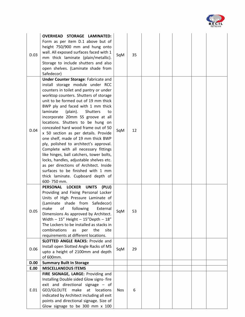
D.03
OVERHEAD STORAGE LAMINATED: Form as per item D.1 above but of height 750/900 mm and hung onto wall. All exposed surfaces faced with 1 mm thick laminate (plain/metallic). Storage to include shutters and also open shelves. (Laminate shade from Safedecor)
SqM 35
D.04
Under Counter Storage: Fabricate and install storage module under RCC counters in toilet and pantry or under worktop counters. Shutters of storage unit to be formed out of 19 mm thick BWP ply and faced with 1 mm thick laminate (plain). Shutters to incorporate 20mm SS groove at all locations. Shutters to be hung on concealed hard wood frame out of 50 x 50 section as per details. Provide one shelf, made of 19 mm thick BWP ply, polished to architect’s approval. Complete with all necessary fittings like hinges, ball catchers, tower bolts, locks, handles, adjustable shelves etc. as per directions of Architect. Inside surfaces to be finished with 1 mm thick laminate. Cupboard depth of 600- 750 mm.
SqM 12
D.05
PERSONAL LOCKER UNITS (PLU) Providing and Fixing Personal Locker Units of High Pressure Laminate of (Laminate shade from Safedecor) make of following External Dimensions As approved by Architect. Width – 15” Height – 15”Depth – 18” The Lockers to be installed as stacks in combinations as per the site requirements at different locations.
SqM 53
D.06
SLOTTED ANGLE RACKS: Provide and Install open Slotted Angle Racks of MS upto a height of 2100mm and depth of 600mm.
SqM 29
D.00 Summary Built In Storage
E.00 MISCELLANEOUS ITEMS
E.01
FIRE SIGNAGE, LARGE: Providing and Installing Double sided Glow signs- fire exit and directional signage – of GEO/GLOLITE make at locations indicated by Architect including all exit points and directional signage. Size of Glow signage to be 300 mm x 100
Nos 6
mm.
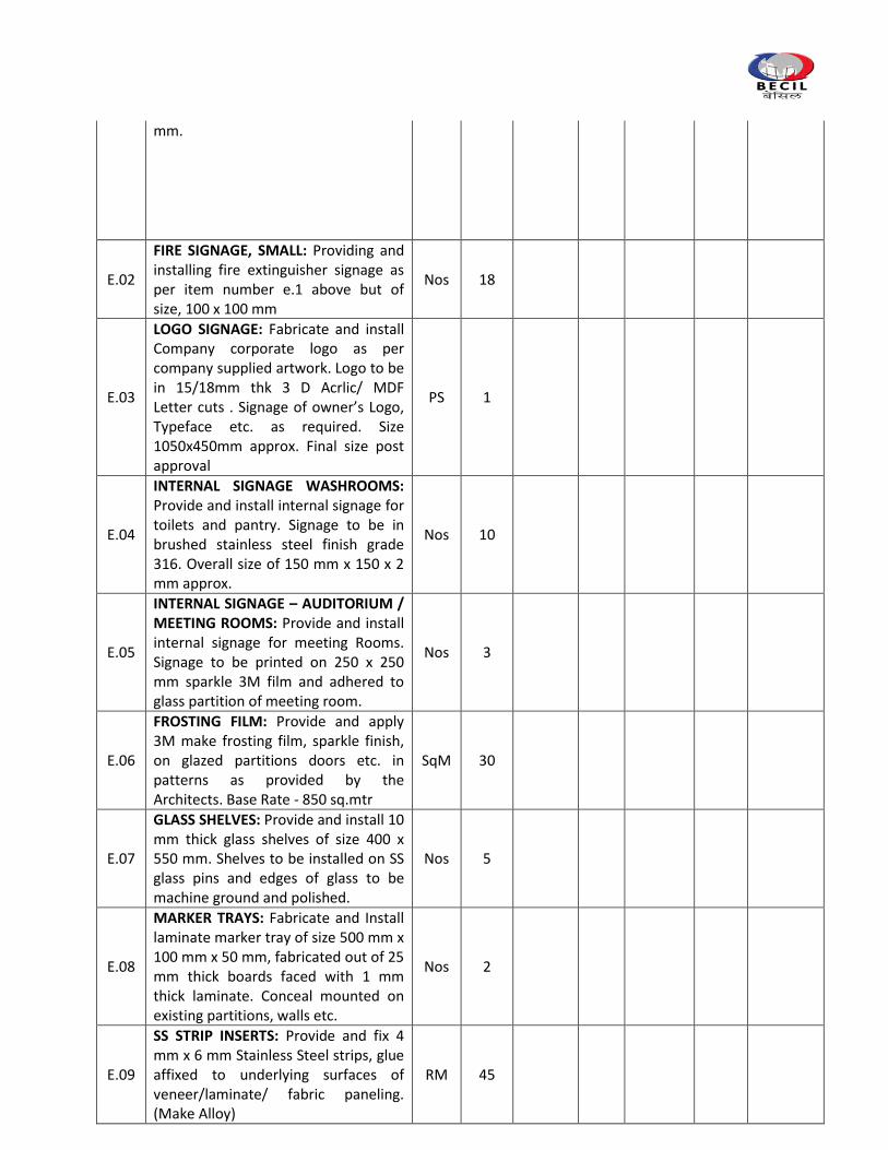
E.02
FIRE SIGNAGE, SMALL: Providing and installing fire extinguisher signage as per item number e.1 above but of size, 100 x 100 mm
Nos 18
E.03
LOGO SIGNAGE: Fabricate and install Company corporate logo as per company supplied artwork. Logo to be in 15/18mm thk 3 D Acrlic/ MDF Letter cuts . Signage of owner’s Logo, Typeface etc. as required. Size 1050x450mm approx. Final size post approval
PS 1
E.04
INTERNAL SIGNAGE WASHROOMS: Provide and install internal signage for toilets and pantry. Signage to be in brushed stainless steel finish grade 316. Overall size of 150 mm x 150 x 2 mm approx.
Nos 10
E.05
INTERNAL SIGNAGE – AUDITORIUM / MEETING ROOMS: Provide and install internal signage for meeting Rooms. Signage to be printed on 250 x 250 mm sparkle 3M film and adhered to glass partition of meeting room.
Nos 3
E.06
FROSTING FILM: Provide and apply 3M make frosting film, sparkle finish, on glazed partitions doors etc. in patterns as provided by the Architects. Base Rate - 850 sq.mtr
SqM 30
E.07
GLASS SHELVES: Provide and install 10 mm thick glass shelves of size 400 x 550 mm. Shelves to be installed on SS glass pins and edges of glass to be machine ground and polished.
Nos 5
E.08
MARKER TRAYS: Fabricate and Install laminate marker tray of size 500 mm x 100 mm x 50 mm, fabricated out of 25 mm thick boards faced with 1 mm thick laminate. Conceal mounted on existing partitions, walls etc.
Nos 2
E.09
SS STRIP INSERTS: Provide and fix 4 mm x 6 mm Stainless Steel strips, glue affixed to underlying surfaces of veneer/laminate/ fabric paneling. (Make Alloy)
RM 45
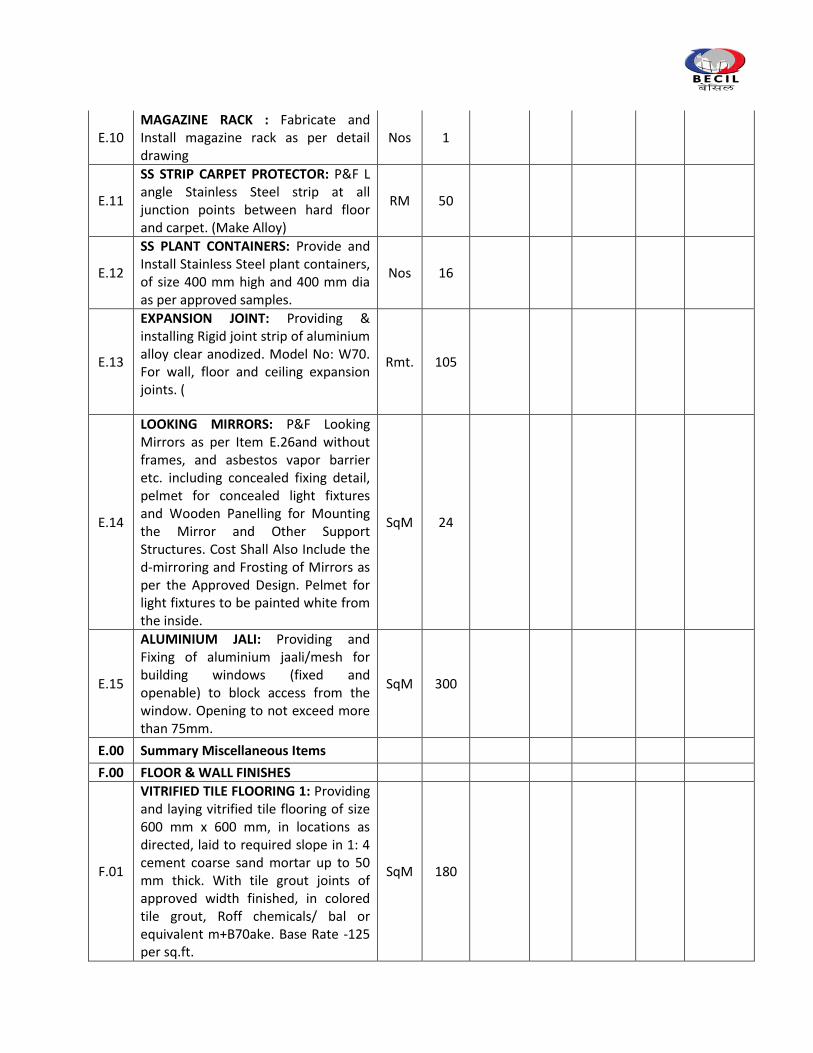
E.10 MAGAZINE RACK : Fabricate and Install magazine rack as per detail drawing
Nos 1
E.11
SS STRIP CARPET PROTECTOR: P&F L angle Stainless Steel strip at all junction points between hard floor and carpet. (Make Alloy)
RM 50
E.12
SS PLANT CONTAINERS: Provide and Install Stainless Steel plant containers, of size 400 mm high and 400 mm dia as per approved samples.
Nos 16
E.13
EXPANSION JOINT: Providing & installing Rigid joint strip of aluminium alloy clear anodized. Model No: W70. For wall, floor and ceiling expansion joints. (
Rmt. 105
E.14
LOOKING MIRRORS: P&F Looking Mirrors as per Item E.26and without frames, and asbestos vapor barrier etc. including concealed fixing detail, pelmet for concealed light fixtures and Wooden Panelling for Mounting the Mirror and Other Support Structures. Cost Shall Also Include the d‐mirroring and Frosting of Mirrors as per the Approved Design. Pelmet for light fixtures to be painted white from the inside.
SqM 24
E.15
ALUMINIUM JALI: Providing and Fixing of aluminium jaali/mesh for building windows (fixed and openable) to block access from the window. Opening to not exceed more than 75mm.
SqM 300
E.00 Summary Miscellaneous Items
F.00 FLOOR & WALL FINISHES
F.01
VITRIFIED TILE FLOORING 1: Providing and laying vitrified tile flooring of size 600 mm x 600 mm, in locations as directed, laid to required slope in 1: 4 cement coarse sand mortar up to 50 mm thick. With tile grout joints of approved width finished, in colored tile grout, Roff chemicals/ bal or equivalent m+B70ake. Base Rate -125 per sq.ft.
SqM 180
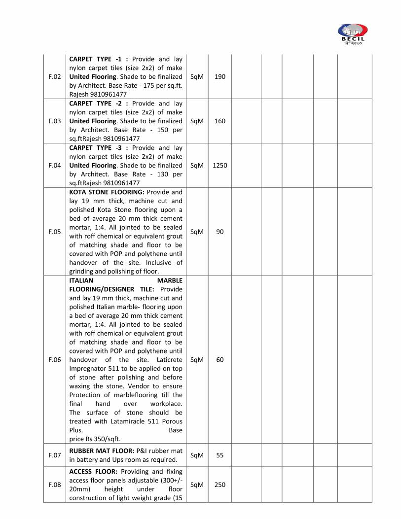
F.02
CARPET TYPE -1 : Provide and lay nylon carpet tiles (size 2x2) of make United Flooring. Shade to be finalized by Architect. Base Rate - 175 per sq.ft. Rajesh 9810961477
SqM 190
F.03
CARPET TYPE -2 : Provide and lay nylon carpet tiles (size 2x2) of make United Flooring. Shade to be finalized by Architect. Base Rate - 150 per sq.ftRajesh 9810961477
SqM 160
F.04
CARPET TYPE -3 : Provide and lay nylon carpet tiles (size 2x2) of make United Flooring. Shade to be finalized by Architect. Base Rate - 130 per sq.ftRajesh 9810961477
SqM 1250
F.05
KOTA STONE FLOORING: Provide and lay 19 mm thick, machine cut and polished Kota Stone flooring upon a bed of average 20 mm thick cement mortar, 1:4. All jointed to be sealed with roff chemical or equivalent grout of matching shade and floor to be covered with POP and polythene until handover of the site. Inclusive of grinding and polishing of floor.
SqM 90
F.06
ITALIAN MARBLE FLOORING/DESIGNER TILE: Provide and lay 19 mm thick, machine cut and polished Italian marble‐ flooring upon a bed of average 20 mm thick cement mortar, 1:4. All jointed to be sealed with roff chemical or equivalent grout of matching shade and floor to be covered with POP and polythene until handover of the site. Laticrete Impregnator 511 to be applied on top of stone after polishing and before waxing the stone. Vendor to ensure Protection of marbleflooring till the final hand over workplace. The surface of stone should be treated with Latamiracle 511 Porous Plus. Base price Rs 350/sqft.
SqM 60
F.07 RUBBER MAT FLOOR: P&I rubber mat in battery and Ups room as required.
SqM 55
F.08
ACCESS FLOOR: Providing and fixing access floor panels adjustable (300+/- 20mm) height under floor construction of light weight grade (15
SqM 250
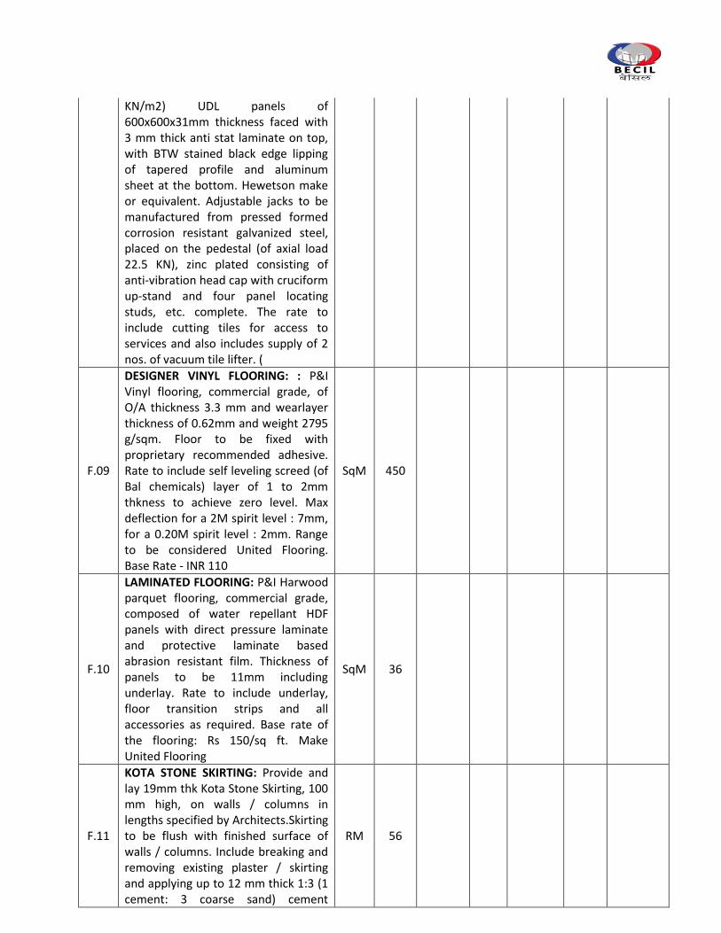
KN/m2) UDL panels of 600x600x31mm thickness faced with 3 mm thick anti stat laminate on top, with BTW stained black edge lipping of tapered profile and aluminum sheet at the bottom. Hewetson make or equivalent. Adjustable jacks to be manufactured from pressed formed corrosion resistant galvanized steel, placed on the pedestal (of axial load 22.5 KN), zinc plated consisting of anti-vibration head cap with cruciform up-stand and four panel locating studs, etc. complete. The rate to include cutting tiles for access to services and also includes supply of 2 nos. of vacuum tile lifter. (
F.09
DESIGNER VINYL FLOORING: : P&I Vinyl flooring, commercial grade, of O/A thickness 3.3 mm and wearlayer thickness of 0.62mm and weight 2795 g/sqm. Floor to be fixed with proprietary recommended adhesive. Rate to include self leveling screed (of Bal chemicals) layer of 1 to 2mm thkness to achieve zero level. Max deflection for a 2M spirit level : 7mm, for a 0.20M spirit level : 2mm. Range to be considered United Flooring. Base Rate - INR 110
SqM 450
F.10
LAMINATED FLOORING: P&I Harwood parquet flooring, commercial grade, composed of water repellant HDF panels with direct pressure laminate and protective laminate based abrasion resistant film. Thickness of panels to be 11mm including underlay. Rate to include underlay, floor transition strips and all accessories as required. Base rate of the flooring: Rs 150/sq ft. Make United Flooring
SqM 36
F.11
KOTA STONE SKIRTING: Provide and lay 19mm thk Kota Stone Skirting, 100 mm high, on walls / columns in lengths specified by Architects.Skirting to be flush with finished surface of walls / columns. Include breaking and removing existing plaster / skirting and applying up to 12 mm thick 1:3 (1 cement: 3 coarse sand) cement
RM 56
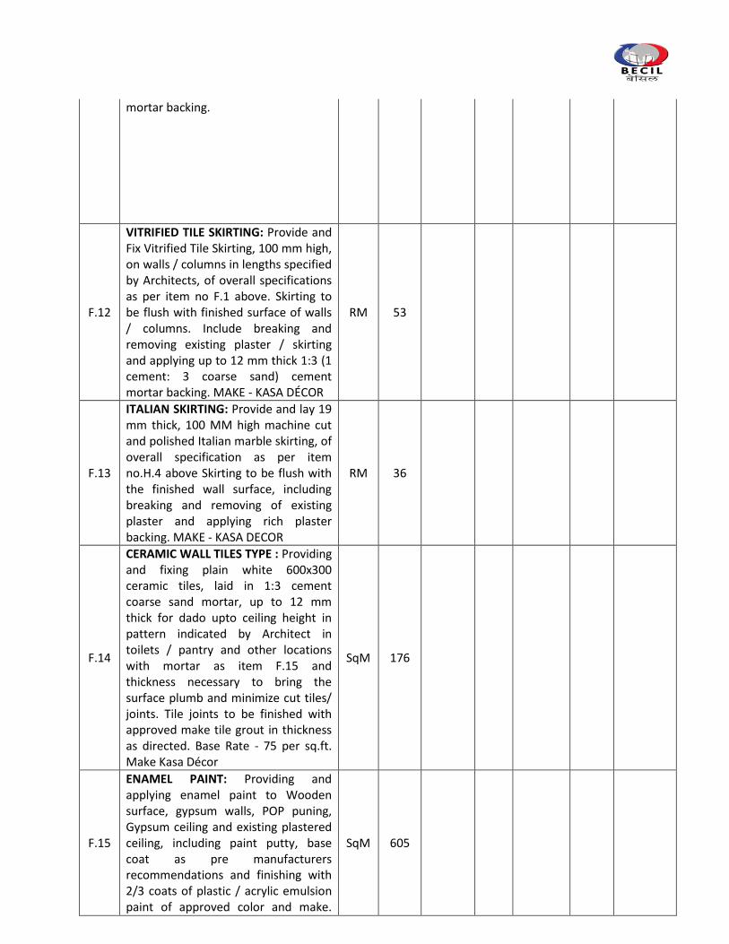
mortar backing.
F.12
VITRIFIED TILE SKIRTING: Provide and Fix Vitrified Tile Skirting, 100 mm high, on walls / columns in lengths specified by Architects, of overall specifications as per item no F.1 above. Skirting to be flush with finished surface of walls / columns. Include breaking and removing existing plaster / skirting and applying up to 12 mm thick 1:3 (1 cement: 3 coarse sand) cement mortar backing. MAKE - KASA DÉCOR
RM 53
F.13
ITALIAN SKIRTING: Provide and lay 19 mm thick, 100 MM high machine cut and polished Italian marble skirting, of overall specification as per item no.H.4 above Skirting to be flush with the finished wall surface, including breaking and removing of existing plaster and applying rich plaster backing. MAKE - KASA DECOR
RM 36
F.14
CERAMIC WALL TILES TYPE : Providing and fixing plain white 600x300 ceramic tiles, laid in 1:3 cement coarse sand mortar, up to 12 mm thick for dado upto ceiling height in pattern indicated by Architect in toilets / pantry and other locations with mortar as item F.15 and thickness necessary to bring the surface plumb and minimize cut tiles/ joints. Tile joints to be finished with approved make tile grout in thickness as directed. Base Rate - 75 per sq.ft. Make Kasa Décor
SqM 176
F.15
ENAMEL PAINT: Providing and applying enamel paint to Wooden surface, gypsum walls, POP puning, Gypsum ceiling and existing plastered ceiling, including paint putty, base coat as pre manufacturers recommendations and finishing with 2/3 coats of plastic / acrylic emulsion paint of approved color and make.
SqM 605
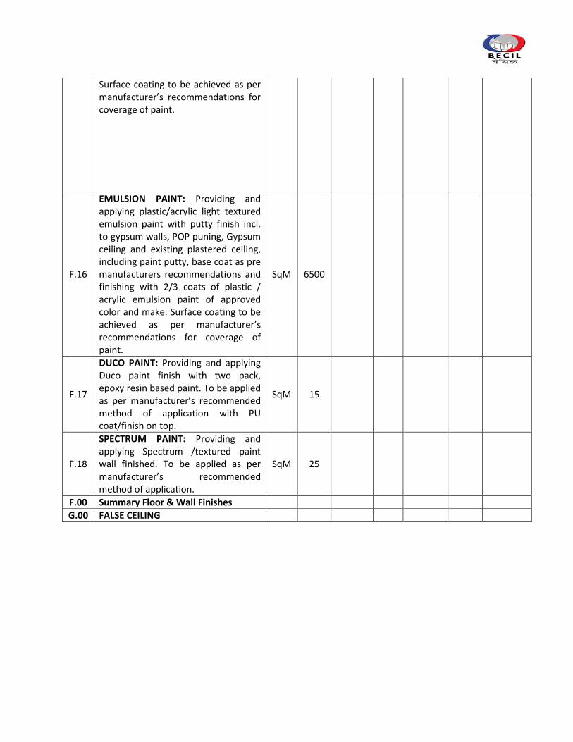
Surface coating to be achieved as per manufacturer’s recommendations for coverage of paint.
F.16
EMULSION PAINT: Providing and applying plastic/acrylic light textured emulsion paint with putty finish incl. to gypsum walls, POP puning, Gypsum ceiling and existing plastered ceiling, including paint putty, base coat as pre manufacturers recommendations and finishing with 2/3 coats of plastic / acrylic emulsion paint of approved color and make. Surface coating to be achieved as per manufacturer’s recommendations for coverage of paint.
SqM 6500
F.17
DUCO PAINT: Providing and applying Duco paint finish with two pack, epoxy resin based paint. To be applied as per manufacturer’s recommended method of application with PU coat/finish on top.
SqM 15
F.18
SPECTRUM PAINT: Providing and applying Spectrum /textured paint wall finished. To be applied as per manufacturer’s recommended method of application.
SqM 25
F.00 Summary Floor & Wall Finishes
G.00 FALSE CEILING
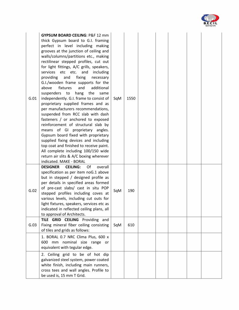
G.01
GYPSUM BOARD CEILING: P&F 12 mm thick Gypsum board to G.I. framing perfect in level including making grooves at the junction of ceiling and walls/columns/partitions etc., making rectilinear stepped profiles, cut out for light fittings, A/C grills, speakers, services etc etc. and including providing and fixing necessary G.I./wooden frame supports for the above fixtures and additional suspenders to hang the same independently. G.I. frame to consist of proprietary supplied frames and as per manufacturers recommendations, suspended from RCC slab with dash fasteners / or anchored to exposed reinforcement of structural slab by means of GI proprietary angles. Gypsum board fixed with proprietary supplied fixing devices and including top coat and finished to receive paint. All complete including 100/150 wide return air slits & A/C boxing wherever indicated. MAKE - BORAL
SqM 1550
G.02
DESIGNER CEILING: Of overall specification as per item noG.1 above but in stepped / designed profile as per details in specified areas formed of pre-cast slabs/ cast in situ POP stepped profiles including coves at various levels, including cut outs for light fixtures, speakers, services etc as indicated in reflected ceiling plans, all to approval of Architects.
SqM 190
G.03 TILE GRID CEILING Providing and Fixing mineral fiber ceiling consisting of tiles and grids as follows:
SqM 610
1. BORAL 0.7 NRC Clima Plus, 600 x 600 mm nominal size range or equivalent with tegular edge.
2. Ceiling grid to be of hot dip galvanized steel system, power coated white finish, including main runners, cross tees and wall angles. Profile to be used is, 15 mm T Grid.
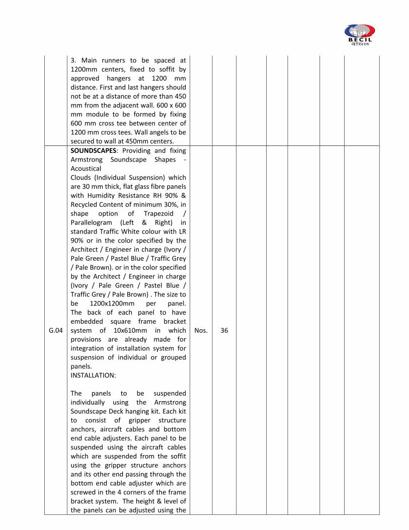
3. Main runners to be spaced at 1200mm centers, fixed to soffit by approved hangers at 1200 mm distance. First and last hangers should not be at a distance of more than 450 mm from the adjacent wall. 600 x 600 mm module to be formed by fixing 600 mm cross tee between center of 1200 mm cross tees. Wall angels to be secured to wall at 450mm centers.
G.04
SOUNDSCAPES: Providing and fixing Armstrong Soundscape Shapes ‐ Acoustical Clouds (Individual Suspension) which are 30 mm thick, flat glass fibre panels with Humidity Resistance RH 90% & Recycled Content of minimum 30%, in shape option of Trapezoid / Parallelogram (Left & Right) in standard Traffic White colour with LR 90% or in the color specified by the Architect / Engineer in charge (Ivory / Pale Green / Pastel Blue / Traffic Grey / Pale Brown). or in the color specified by the Architect / Engineer in charge (Ivory / Pale Green / Pastel Blue / Traffic Grey / Pale Brown) . The size to be 1200x1200mm per panel. The back of each panel to have embedded square frame bracket system of 10x610mm in which provisions are already made for integration of installation system for suspension of individual or grouped panels. INSTALLATION: The panels to be suspended individually using the Armstrong Soundscape Deck hanging kit. Each kit to consist of gripper structure anchors, aircraft cables and bottom end cable adjusters. Each panel to be suspended using the aircraft cables which are suspended from the soffit using the gripper structure anchors and its other end passing through the bottom end cable adjuster which are screwed in the 4 corners of the frame bracket system. The height & level of the panels can be adjusted using the
Nos. 36
bottom end cable adjusters.
G.05
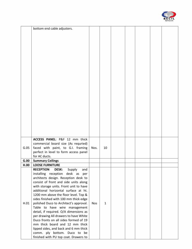
ACCESS PANEL: P&F 12 mm thick commercial board size (As requried) faced with paint, to G.I. framing perfect in level to form access panel for AC ducts.
Nos. 10
G.00 Summary Ceilings
H.00 LOOSE FURNITURE
H.01
RECEPTION DESK: Supply and installing reception desk as per architects design. Reception desk to consist of front and side units along with storage units. Front unit to have additional horizontal surface at ht. 1200 mm above the floor level. Top & sides finished with 100 mm thick edge polished Duco to Architect’s approval. Table to have wire management detail, if required. O/A dimensions as per drawing All drawers to have White Duco fronts on all sides formed of 19 mm thick board and 12 mm thick lipped sides, and back and 6 mm thick comm. ply bottom. Duco to be finished with PU top coat. Drawers to
Nos 1
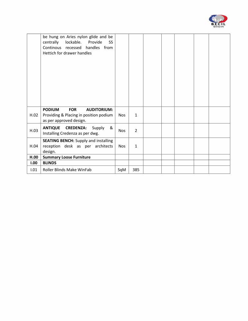
be hung on Aries nylon glide and be centrally lockable. Provide SS Continous recessed handles from Hettich for drawer handles
H.02 PODIUM FOR AUDITORIUM: Providing & Placing in position podium as per approved design.
Nos 1
H.03 ANTIQUE CREDENZA: Supply & Installing Credenza as per dwg.
Nos 2
H.04 SEATING BENCH: Supply and installing reception desk as per architects design.
Nos 1
H.00 Summary Loose Furniture
I.00 BLINDS
I.01 Roller Blinds Make WinFab SqM 385
2. ELECTRICAL WORK
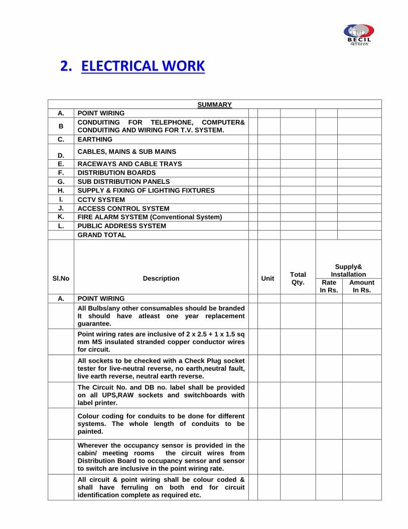
SUMMARY
A. POINT WIRING
B CONDUITING FOR TELEPHONE, COMPUTER& CONDUITING AND WIRING FOR T.V. SYSTEM.
C. EARTHING
D.
CABLES, MAINS & SUB MAINS
E. RACEWAYS AND CABLE TRAYS
F. DISTRIBUTION BOARDS
G. SUB DISTRIBUTION PANELS
H. SUPPLY & FIXING OF LIGHTING FIXTURES
I. CCTV SYSTEM
J. ACCESS CONTROL SYSTEM
K. FIRE ALARM SYSTEM (Conventional System)
L. PUBLIC ADDRESS SYSTEM
GRAND TOTAL
Sl.No
Description
Unit
Total Qty.
Supply& Installation
Rate In Rs.
Amount In Rs.
A. POINT WIRING
All Bulbs/any other consumables should be branded It should have atleast one year replacement guarantee.
Point wiring rates are inclusive of 2 x 2.5 + 1 x 1.5 sq mm MS insulated stranded copper conductor wires for circuit.
All sockets to be checked with a Check Plug socket tester for live-neutral reverse, no earth,neutral fault, live earth reverse, neutral earth reverse.
The Circuit No. and DB no. label shall be provided on all UPS,RAW sockets and switchboards with label printer.
Colour coding for conduits to be done for different systems. The whole length of conduits to be painted.
Wherever the occupancy sensor is provided in the cabin/ meeting rooms the circuit wires from Distribution Board to occupancy sensor and sensor to switch are inclusive in the point wiring rate.
All circuit & point wiring shall be colour coded & shall have ferruling on both end for circuit identification complete as required etc.
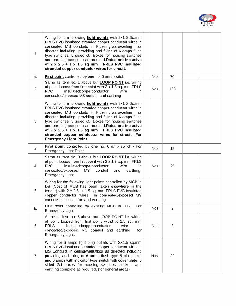
1
Wiring for the following light points with 3x1.5 Sq.mm FRLS PVC insulated stranded copper conductor wires in concealed MS conduits in F.ceiling/walls/ceiling as directed including providing and fixing of 6 amps flush type switches, 5 sided G.I Boxes for housing switches and earthing complete as required.Rates are inclusive of 2 x 2.5 + 1 x 1.5 sq mm FRLS PVC insulated stranded copper conductor wires for circuit.
a. First point controlled by one no. 6 amp switch.
Nos. 70
2
Same as item No. 1 above but LOOP POINT i.e. wiring of point looped from first point with 3 x 1.5 sq. mm FRLS PVC insulatedcopperconductor wire in concealed/exposed MS conduit and earthing
Nos. 130
3
Wiring for the following light points with 3x1.5 Sq.mm FRLS PVC insulated stranded copper conductor wires in concealed MS conduits in F.ceiling/walls/ceiling as directed including providing and fixing of 6 amps flush type switches, 5 sided G.I Boxes for housing switches and earthing complete as required.Rates are inclusive of 2 x 2.5 + 1 x 1.5 sq mm FRLS PVC insulated stranded copper conductor wires for circuit- For Emergency Light Point
a First point controlled by one no. 6 amp switch.- For Emergency Light Point
Nos. 18
4
Same as item No. 3 above but LOOP POINT i.e. wiring of point looped from first point with 3 x 1.5 sq. mm FRLS PVC insulatedcopperconductor wire in concealed/exposed MS conduit and earthing- Emergency Light
Nos. 25
5
Wiring for the following light points controlled by MCB in DB (Cost of MCB has been taken elsewhere in the tender) with 2 x 2.5 + 1.5 sq. mm FRLS PVC insulated copper conductor wires in concealed/exposed MS conduits as called for and earthing.
a. First point controlled by existing MCB in D.B. For Emergency Light
Nos. 2
6
Same as item no. 5 above but LOOP POINT i.e. wiring of point looped from first point with3 X 1.5 sq. mm FRLS. Insulatedcopperconductor wire in concealed/exposed MS conduit and earthing for Emergency Light.
Nos. 8
7
Wiring for 6 amps light plug outlets with 3X1.5 sq.mm FRLS PVC insulated stranded copper conductor wires in MS Conduits in ceiling/walls/floor as directed including providing and fixing of 6 amps flush type 5 pin socket and 6 amps with indicator type switch with cover plate, 5 sided G.I boxes for housing switches, sockets and earthing complete as required. (for general areas)
Nos. 22
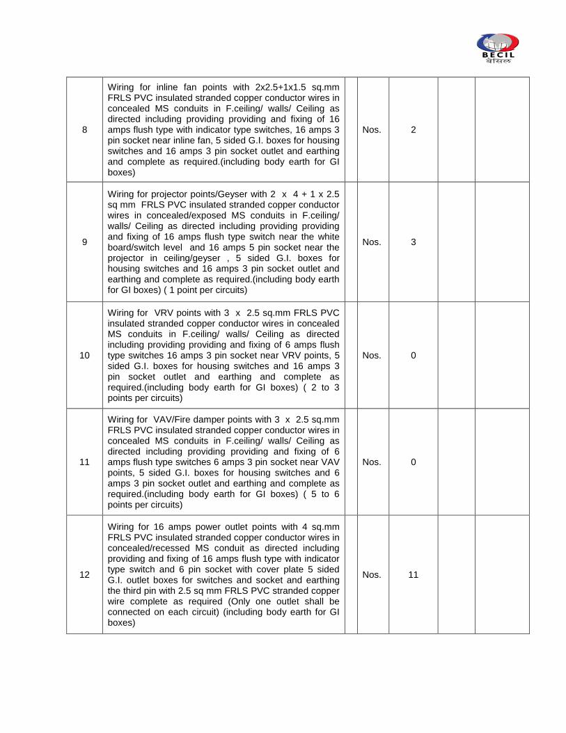
8
Wiring for inline fan points with 2x2.5+1x1.5 sq.mm FRLS PVC insulated stranded copper conductor wires in concealed MS conduits in F.ceiling/ walls/ Ceiling as directed including providing providing and fixing of 16 amps flush type with indicator type switches, 16 amps 3 pin socket near inline fan, 5 sided G.I. boxes for housing switches and 16 amps 3 pin socket outlet and earthing and complete as required.(including body earth for GI boxes)
Nos. 2
9
Wiring for projector points/Geyser with 2 x 4 + 1 x 2.5 sq mm FRLS PVC insulated stranded copper conductor wires in concealed/exposed MS conduits in F.ceiling/ walls/ Ceiling as directed including providing providing and fixing of 16 amps flush type switch near the white board/switch level and 16 amps 5 pin socket near the projector in ceiling/geyser , 5 sided G.I. boxes for housing switches and 16 amps 3 pin socket outlet and earthing and complete as required.(including body earth for GI boxes) ( 1 point per circuits)
Nos. 3
10
Wiring for VRV points with 3 x 2.5 sq.mm FRLS PVC insulated stranded copper conductor wires in concealed MS conduits in F.ceiling/ walls/ Ceiling as directed including providing providing and fixing of 6 amps flush type switches 16 amps 3 pin socket near VRV points, 5 sided G.I. boxes for housing switches and 16 amps 3 pin socket outlet and earthing and complete as required.(including body earth for GI boxes) ( 2 to 3 points per circuits)
Nos. 0
11
Wiring for VAV/Fire damper points with 3 x 2.5 sq.mm FRLS PVC insulated stranded copper conductor wires in concealed MS conduits in F.ceiling/ walls/ Ceiling as directed including providing providing and fixing of 6 amps flush type switches 6 amps 3 pin socket near VAV points, 5 sided G.I. boxes for housing switches and 6 amps 3 pin socket outlet and earthing and complete as required.(including body earth for GI boxes) ( 5 to 6 points per circuits)
Nos. 0
12
Wiring for 16 amps power outlet points with 4 sq.mm FRLS PVC insulated stranded copper conductor wires in concealed/recessed MS conduit as directed including providing and fixing of 16 amps flush type with indicator type switch and 6 pin socket with cover plate 5 sided G.I. outlet boxes for switches and socket and earthing the third pin with 2.5 sq mm FRLS PVC stranded copper wire complete as required (Only one outlet shall be connected on each circuit) (including body earth for GI boxes)
Nos. 11
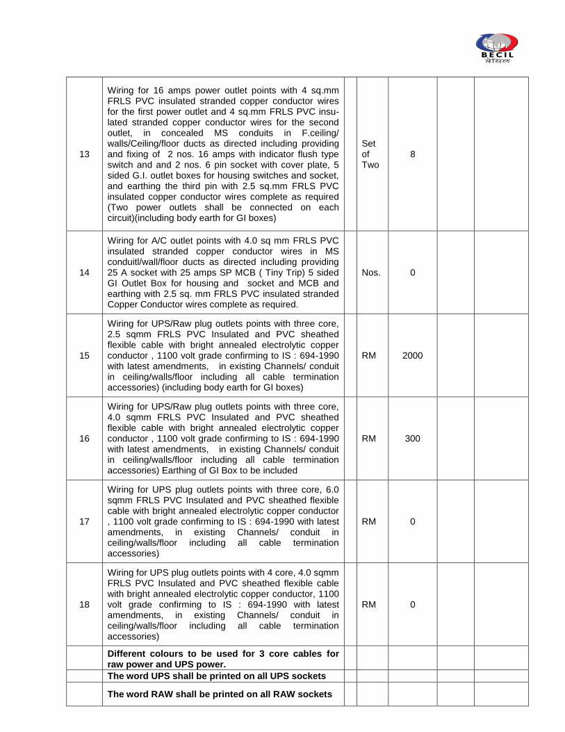
13
Wiring for 16 amps power outlet points with 4 sq.mm FRLS PVC insulated stranded copper conductor wires for the first power outlet and 4 sq.mm FRLS PVC insu-lated stranded copper conductor wires for the second outlet, in concealed MS conduits in F.ceiling/ walls/Ceiling/floor ducts as directed including providing and fixing of 2 nos. 16 amps with indicator flush type switch and and 2 nos. 6 pin socket with cover plate, 5 sided G.I. outlet boxes for housing switches and socket, and earthing the third pin with 2.5 sq.mm FRLS PVC insulated copper conductor wires complete as required (Two power outlets shall be connected on each circuit)(including body earth for GI boxes)
Set of Two
8
14
Wiring for A/C outlet points with 4.0 sq mm FRLS PVC insulated stranded copper conductor wires in MS conduitl/wall/floor ducts as directed including providing 25 A socket with 25 amps SP MCB ( Tiny Trip) 5 sided GI Outlet Box for housing and socket and MCB and earthing with 2.5 sq. mm FRLS PVC insulated stranded Copper Conductor wires complete as required.
Nos. 0
15
Wiring for UPS/Raw plug outlets points with three core, 2.5 sqmm FRLS PVC Insulated and PVC sheathed flexible cable with bright annealed electrolytic copper conductor , 1100 volt grade confirming to IS : 694-1990 with latest amendments, in existing Channels/ conduit in ceiling/walls/floor including all cable termination accessories) (including body earth for GI boxes)
RM 2000
16
Wiring for UPS/Raw plug outlets points with three core, 4.0 sqmm FRLS PVC Insulated and PVC sheathed flexible cable with bright annealed electrolytic copper conductor , 1100 volt grade confirming to IS : 694-1990 with latest amendments, in existing Channels/ conduit in ceiling/walls/floor including all cable termination accessories) Earthing of GI Box to be included
RM 300
17
Wiring for UPS plug outlets points with three core, 6.0 sqmm FRLS PVC Insulated and PVC sheathed flexible cable with bright annealed electrolytic copper conductor , 1100 volt grade confirming to IS : 694-1990 with latest amendments, in existing Channels/ conduit in ceiling/walls/floor including all cable termination accessories)
RM 0
18
Wiring for UPS plug outlets points with 4 core, 4.0 sqmm FRLS PVC Insulated and PVC sheathed flexible cable with bright annealed electrolytic copper conductor, 1100 volt grade confirming to IS : 694-1990 with latest amendments, in existing Channels/ conduit in ceiling/walls/floor including all cable termination accessories)
RM 0
Different colours to be used for 3 core cables for raw power and UPS power.
The word UPS shall be printed on all UPS sockets
The word RAW shall be printed on all RAW sockets
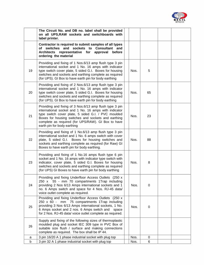
The Circuit No. and DB no. label shall be provided on all UPS,RAW sockets and switchboards with label printer.
Contractor is required to submit samples of all types of switches and sockets to Consultant and Architects representative for approval before ordering the material
19
Providing and fixing of 1 Nos.6/13 amp flush type 3 pin international socket and 1 No. 16 amps with indicator type switch cover plate, 5 sided G.I. Boxes for housing switches and sockets and earthing complete as required (for UPS). GI Box to have earth pin for body earthing
Nos. 5
20
Providing and fixing of 2 Nos.6/13 amp flush type 3 pin international socket and 1 No. 16 amps with indicator type switch cover plate, 5 sided G.I. Boxes for housing switches and sockets and earthing complete as required (for UPS). GI Box to have earth pin for body earthing
Nos. 65
21
Providing and fixing of 3 Nos.6/13 amp flush type 3 pin international socket and 1 No. 16 amps with indicator type switch cover plate, 5 sided G.I. / PVC moulded Boxes for housing switches and sockets and earthing complete as required (for UPS/RAW). GI Box to have earth pin for body earthing
Nos. 23
22
Providing and fixing of 1 No.6/13 amp flush type 3 pin international socket and 1 No. 6 amps switch with cover plate, 5 sided G.I. Boxes for housing switches and sockets and earthing complete as required (for Raw) GI Boxes to have earth pin for body earthing.
Nos. 88
23
Providing and fixing of 1 No.16 amps flush type 6 pin socket and 1 No. 16 amps with indicator type switch with indicator, cover plate, 5 sided G.I. Boxes for housing switches and sockets and earthing complete as required (for UPS) GI Boxes to have earth pin for body earthing
Nos. 8
24
Providing and fixing Underfloor Access Outlets (250 x 250 x 55 - mm 70 compartments 1Trap including providing 2 Nos 6/13 Amps international sockets and 1 no. 6 Amps switch and space for 4 Nos. RJ-45 data/ voice outlet complete as required.
Nos. 0
25
Providing and fixing Underfloor Access Outlets (250 x 250 x 60 - mm 75 compartments 1Trap including providing 3 Nos 6/13 Amps international sockets, 1 No. 6 Amps socket and 2 nos. 6 Amps switch and space for 2 Nos. RJ-45 data/ voice outlet complete as required.
Nos. 0
26
Supply and fixing of the following sizes of thermoplastic moulded plug and socket IEC 309 type in PVC Box of suitable size flush / surface and making connections complete as required. The box shall be IP 44.
a 3 pin 16/20 A 1 phase industrial socket with plug top
Nos. 0
b 3 pin 32 A 1 phase industrial socket with plug top
Nos. 6
27
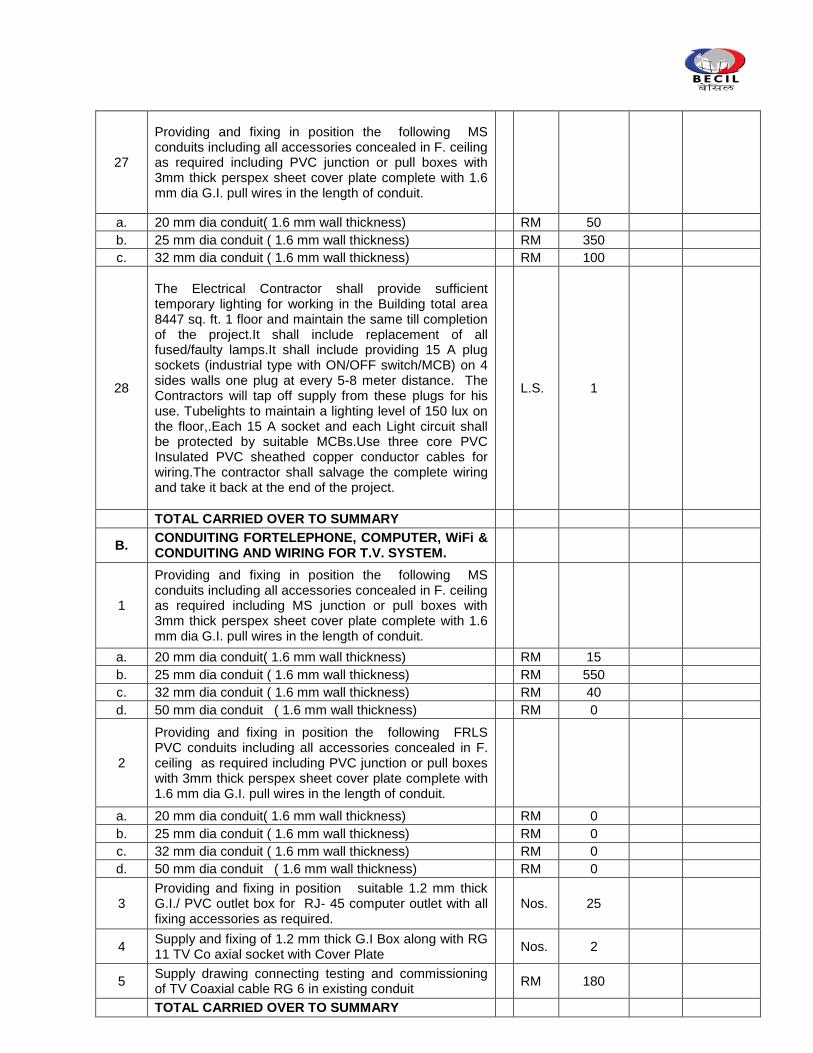
Providing and fixing in position the following MS conduits including all accessories concealed in F. ceiling as required including PVC junction or pull boxes with 3mm thick perspex sheet cover plate complete with 1.6 mm dia G.I. pull wires in the length of conduit.
a. 20 mm dia conduit( 1.6 mm wall thickness)
RM 50
b. 25 mm dia conduit ( 1.6 mm wall thickness)
RM 350
c. 32 mm dia conduit ( 1.6 mm wall thickness)
RM 100
28
The Electrical Contractor shall provide sufficient temporary lighting for working in the Building total area 8447 sq. ft. 1 floor and maintain the same till completion of the project.It shall include replacement of all fused/faulty lamps.It shall include providing 15 A plug sockets (industrial type with ON/OFF switch/MCB) on 4 sides walls one plug at every 5-8 meter distance. The Contractors will tap off supply from these plugs for his use. Tubelights to maintain a lighting level of 150 lux on the floor,.Each 15 A socket and each Light circuit shall be protected by suitable MCBs.Use three core PVC Insulated PVC sheathed copper conductor cables for wiring.The contractor shall salvage the complete wiring and take it back at the end of the project.
L.S. 1
TOTAL CARRIED OVER TO SUMMARY
B. CONDUITING FORTELEPHONE, COMPUTER, WiFi & CONDUITING AND WIRING FOR T.V. SYSTEM.
1
Providing and fixing in position the following MS conduits including all accessories concealed in F. ceiling as required including MS junction or pull boxes with 3mm thick perspex sheet cover plate complete with 1.6 mm dia G.I. pull wires in the length of conduit.
a. 20 mm dia conduit( 1.6 mm wall thickness)
RM 15
b. 25 mm dia conduit ( 1.6 mm wall thickness)
RM 550
c. 32 mm dia conduit ( 1.6 mm wall thickness)
RM 40
d. 50 mm dia conduit ( 1.6 mm wall thickness)
RM 0
2
Providing and fixing in position the following FRLS PVC conduits including all accessories concealed in F. ceiling as required including PVC junction or pull boxes with 3mm thick perspex sheet cover plate complete with 1.6 mm dia G.I. pull wires in the length of conduit.
a. 20 mm dia conduit( 1.6 mm wall thickness)
RM 0
b. 25 mm dia conduit ( 1.6 mm wall thickness)
RM 0
c. 32 mm dia conduit ( 1.6 mm wall thickness)
RM 0
d. 50 mm dia conduit ( 1.6 mm wall thickness)
RM 0
3 Providing and fixing in position suitable 1.2 mm thick G.I./ PVC outlet box for RJ- 45 computer outlet with all fixing accessories as required.
Nos. 25
4 Supply and fixing of 1.2 mm thick G.I Box along with RG 11 TV Co axial socket with Cover Plate
Nos. 2
5 Supply drawing connecting testing and commissioning of TV Coaxial cable RG 6 in existing conduit
RM 180
TOTAL CARRIED OVER TO SUMMARY
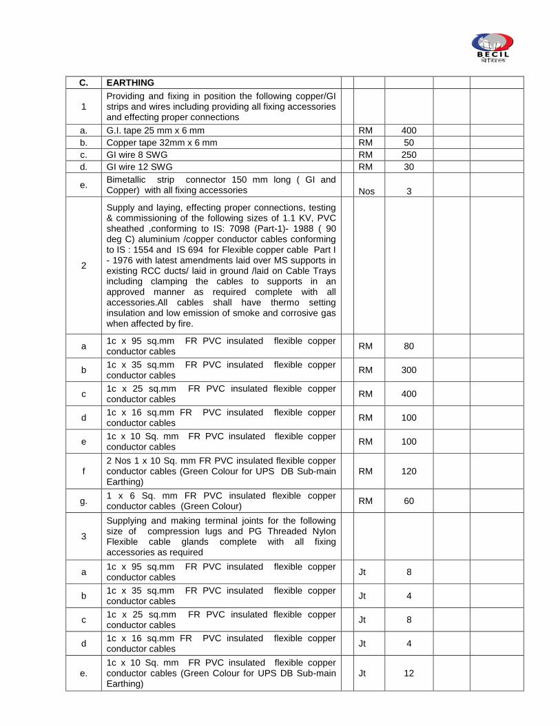
C. EARTHING
1 Providing and fixing in position the following copper/GI strips and wires including providing all fixing accessories and effecting proper connections
a. G.I. tape 25 mm x 6 mm
RM 400
b. Copper tape 32mm x 6 mm
RM 50
c. GI wire 8 SWG
RM 250
d. GI wire 12 SWG
RM 30
e. Bimetallic strip connector 150 mm long ( GI and Copper) with all fixing accessories
Nos 3
2
Supply and laying, effecting proper connections, testing & commissioning of the following sizes of 1.1 KV, PVC sheathed ,conforming to IS: 7098 (Part-1)- 1988 ( 90 deg C) aluminium /copper conductor cables conforming to IS : 1554 and IS 694 for Flexible copper cable Part I - 1976 with latest amendments laid over MS supports in existing RCC ducts/ laid in ground /laid on Cable Trays including clamping the cables to supports in an approved manner as required complete with all accessories.All cables shall have thermo setting insulation and low emission of smoke and corrosive gas when affected by fire.
a 1c x 95 sq.mm FR PVC insulated flexible copper conductor cables
RM 80
b 1c x 35 sq.mm FR PVC insulated flexible copper conductor cables
RM 300
c 1c x 25 sq.mm FR PVC insulated flexible copper conductor cables
RM 400
d 1c x 16 sq.mm FR PVC insulated flexible copper conductor cables
RM 100
e 1c x 10 Sq. mm FR PVC insulated flexible copper conductor cables
RM 100
f 2 Nos 1 x 10 Sq. mm FR PVC insulated flexible copper conductor cables (Green Colour for UPS DB Sub-main Earthing)
RM 120
g. 1 x 6 Sq. mm FR PVC insulated flexible copper conductor cables (Green Colour)
RM 60
3
Supplying and making terminal joints for the following size of compression lugs and PG Threaded Nylon Flexible cable glands complete with all fixing accessories as required
a 1c x 95 sq.mm FR PVC insulated flexible copper conductor cables
Jt 8
b 1c x 35 sq.mm FR PVC insulated flexible copper conductor cables
Jt 4
c 1c x 25 sq.mm FR PVC insulated flexible copper conductor cables
Jt 8
d 1c x 16 sq.mm FR PVC insulated flexible copper conductor cables
Jt 4
e. 1c x 10 Sq. mm FR PVC insulated flexible copper conductor cables (Green Colour for UPS DB Sub-main Earthing)
Jt 12
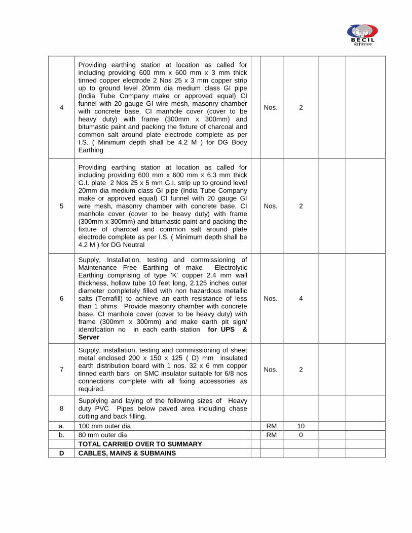
4
Providing earthing station at location as called for including providing 600 mm x 600 mm x 3 mm thick tinned copper electrode 2 Nos 25 x 3 mm copper strip up to ground level 20mm dia medium class GI pipe (India Tube Company make or approved equal) CI funnel with 20 gauge GI wire mesh, masonry chamber with concrete base, CI manhole cover (cover to be heavy duty) with frame (300mm x 300mm) and bitumastic paint and packing the fixture of charcoal and common salt around plate electrode complete as per I.S. ( Minimum depth shall be 4.2 M ) for DG Body Earthing
Nos. 2
5
Providing earthing station at location as called for including providing 600 mm x 600 mm x 6.3 mm thick G.I. plate 2 Nos 25 x 5 mm G.I. strip up to ground level 20mm dia medium class GI pipe (India Tube Company make or approved equal) CI funnel with 20 gauge GI wire mesh, masonry chamber with concrete base, CI manhole cover (cover to be heavy duty) with frame (300mm x 300mm) and bitumastic paint and packing the fixture of charcoal and common salt around plate electrode complete as per I.S. ( Minimum depth shall be 4.2 M ) for DG Neutral
Nos. 2
6
Supply, Installation, testing and commissioning of Maintenance Free Earthing of make Electrolytic Earthing comprising of type 'K' copper 2.4 mm wall thickness, hollow tube 10 feet long, 2.125 inches outer diameter completely filled with non hazardous metallic salts (Terrafill) to achieve an earth resistance of less than 1 ohms. Provide masonry chamber with concrete base, CI manhole cover (cover to be heavy duty) with frame (300mm x 300mm) and make earth pit sign/ identifcation no in each earth station for UPS & Server
Nos. 4
7
Supply, installation, testing and commissioning of sheet metal enclosed 200 x 150 x 125 ( D) mm insulated earth distribution board with 1 nos. 32 x 6 mm copper tinned earth bars on SMC insulator suitable for 6/8 nos connections complete with all fixing accessories as required.
Nos. 2
8 Supplying and laying of the following sizes of Heavy duty PVC Pipes below paved area including chase cutting and back filling.
a. 100 mm outer dia
RM 10
b. 80 mm outer dia
RM 0
TOTAL CARRIED OVER TO SUMMARY
D CABLES, MAINS & SUBMAINS
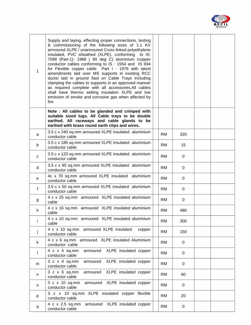
1
Supply and laying, effecting proper connections, testing & commissioning of the following sizes of 1.1 KV armoured XLPE / unarmoured Cross linked polyethylene insulated, PVC sheathed (XLPE), conforming to IS: 7098 (Part-1)- 1988 ( 90 deg C) aluminium /copper conductor cables conforming to IS : 1554 and IS 694 for Flexible copper cable Part I - 1976 with latest amendments laid over MS supports in existing RCC ducts/ laid in ground /laid on Cable Trays including clamping the cables to supports in an approved manner as required complete with all accessories.All cables shall have thermo setting insulation XLPE and low emission of smoke and corrosive gas when affected by fire
Note : All cables to be glanded and crimped with suitable sized lugs. All Cable trays to be double earthed. All raceways and cable glands to be earthed with brass round earth clips and wires.
a 3.5 c x 240 sq.mm armoured XLPE insulated aluminium conductor cable
RM 320
b 3.5 c x 185 sq.mm armoured XLPE insulated aluminium conductor cable
RM 15
c 3.5 c x 120 sq.mm armoured XLPE insulated aluminium conductor cable
RM 0
d 3.5 c x 95 sq.mm armoured XLPE insulated aluminium conductor cable
RM 0
e 4c x 70 sq.mm armoured XLPE insulated aluminium conductor cable
RM 0
f 3.5 c x 50 sq.mm armoured XLPE insulated aluminium conductor cable
RM 0
g 4 c x 25 sq.mm armoured XLPE insulated aluminium cable
RM 0
h 4 c x 16 sq.mm armoured XLPE insulated aluminium cable
RM 480
i 4 c x 10 sq.mm armoured XLPE insulated aluminium cable
RM 300
j 4 c x 10 sq.mm armoured XLPE insulated copper conductor cable
RM 150
k 4 c x 6 sq.mm armoured XLPE insulated Aluminium conductor cable
RM 0
l 4 c x 4 sq.mm armoured XLPE insulated copper conductor cable
RM 0
m 3 c x 4 sq.mm armoured XLPE insulated copper conductor cable
RM 0
n 3 c x 6 sq.mm armoured XLPE insulated copper conductor cable
RM 60
o 3 c x 10 sq.mm armoured XLPE insulated copper conductor cable
RM 0
p 3 c x 10 sq.mm XLPE insulated copper flexible conductor cable
RM 20
q 4 c x 2.5 sq.mm armoured XLPE insulated copper conductor cable
RM 0
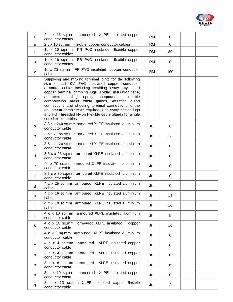
r 2 c x 16 sq.mm armoured XLPE insulated copper conductor cables
RM 0
s 2 c x 10 sq.mm Flexible copper conductor cables
RM 0
t 1c x 10 sq.mm FR PVC insulated flexible copper conductor cables
RM 80
u 1c x 16 sq.mm FR PVC insulated flexible copper conductor cables
RM 0
v 1c x 25 sq.mm FR PVC insulated copper conductor cables
RM 160
2
Supplying and making terminal joints for the following size of 1.1 KV PVC insulated copper conductor armoured cables including providing heavy duty tinned copper terminal crimping lugs, solder, insulation tape, approved sealing epoxy compound, double compression brass cable glands, effecting gland connections and effecting terminal connections to the equipment complete as required. Use compression lugs and PG Threaded Nylon Flexible cable glands for single core flexible cables
a 3.5 c x 240 sq.mm armoured XLPE insulated aluminium conductor cable
Jt 6
b 3.5 c x 185 sq.mm armoured XLPE insulated aluminium conductor cable
Jt 2
c 3.5 c x 120 sq.mm armoured XLPE insulated aluminium conductor cable
Jt 0
d 3.5 c x 95 sq.mm armoured XLPE insulated aluminium conductor cable
Jt 0
e 4c x 70 sq.mm armoured XLPE insulated aluminium conductor cable
Jt 0
f 3.5 c x 50 sq.mm armoured XLPE insulated aluminium conductor cable
Jt 0
g 4 c x 25 sq.mm armoured XLPE insulated aluminium cable
Jt 0
h 4 c x 16 sq.mm armoured XLPE insulated aluminium cable
Jt 14
i 4 c x 10 sq.mm armoured XLPE insulated aluminium cable
Jt 10
j 4 c x 10 sq.mm armoured XLPE insulated aluminum conductor cable
Jt 8
k 4 c x 10 sq.mm armoured XLPE insulated copper conductor cable
Jt 10
l 4 c x 6 sq.mm armoured XLPE insulated Aluminium conductor cable
Jt 0
m 4 c x 4 sq.mm armoured XLPE insulated copper conductor cable
Jt 0
n 3 c x 4 sq.mm armoured XLPE insulated copper conductor cable
Jt 0
o 3 c x 6 sq.mm armoured XLPE insulated copper conductor cable
Jt 6
p 3 c x 10 sq.mm armoured XLPE insulated copper conductor cable
Jt 0
q 3 c x 10 sq.mm XLPE insulated copper flexible conductor cable
Jt 2
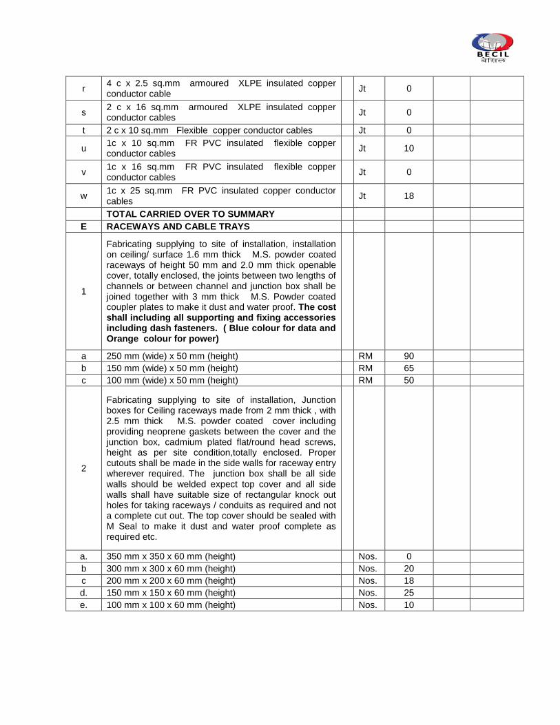
r 4 c x 2.5 sq.mm armoured XLPE insulated copper conductor cable
Jt 0
s 2 c x 16 sq.mm armoured XLPE insulated copper conductor cables
Jt 0
t 2 c x 10 sq.mm Flexible copper conductor cables
Jt 0
u 1c x 10 sq.mm FR PVC insulated flexible copper conductor cables
Jt 10
v 1c x 16 sq.mm FR PVC insulated flexible copper conductor cables
Jt 0
w 1c x 25 sq.mm FR PVC insulated copper conductor cables
Jt 18
TOTAL CARRIED OVER TO SUMMARY
E RACEWAYS AND CABLE TRAYS
1
Fabricating supplying to site of installation, installation on ceiling/ surface 1.6 mm thick M.S. powder coated raceways of height 50 mm and 2.0 mm thick openable cover, totally enclosed, the joints between two lengths of channels or between channel and junction box shall be joined together with 3 mm thick M.S. Powder coated coupler plates to make it dust and water proof. The cost shall including all supporting and fixing accessories including dash fasteners. ( Blue colour for data and Orange colour for power)
a 250 mm (wide) x 50 mm (height)
RM 90
b 150 mm (wide) x 50 mm (height)
RM 65
c 100 mm (wide) x 50 mm (height)
RM 50
2
Fabricating supplying to site of installation, Junction boxes for Ceiling raceways made from 2 mm thick , with 2.5 mm thick M.S. powder coated cover including providing neoprene gaskets between the cover and the junction box, cadmium plated flat/round head screws, height as per site condition,totally enclosed. Proper cutouts shall be made in the side walls for raceway entry wherever required. The junction box shall be all side walls should be welded expect top cover and all side walls shall have suitable size of rectangular knock out holes for taking raceways / conduits as required and not a complete cut out. The top cover should be sealed with M Seal to make it dust and water proof complete as required etc.
a. 350 mm x 350 x 60 mm (height)
Nos. 0
b 300 mm x 300 x 60 mm (height)
Nos. 20
c 200 mm x 200 x 60 mm (height)
Nos. 18
d. 150 mm x 150 x 60 mm (height)
Nos. 25
e. 100 mm x 100 x 60 mm (height)
Nos. 10
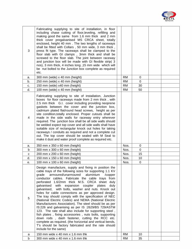
3
Fabricating supplying to site of installation, in floor including chase cutting of floor,leveling, refilling and making good the same from 1.6 mm thick and 2 mm thick cover pregalvanised MS CRCA sheet, totally enclosed, height 40 mm . The two lengths of raceways shall be fitted with Collars , 50 mm wide, 3 mm thick , press fit type. The raceways shall be clamped to the floor slab with GI clamps , 3mm thick and shall be screwed to the floor slab. The joint between raceway and junction box will be made with GI flexible strip( 3 nos), 3 mm thick, 4 inches long ,15 mm wide which will be nut bolted to the Junction box complete as required etc.
a. 300 mm (wide) x 40 mm (height)
RM 0
b. 250 mm (wide) x 40 mm (height)
RM 0
c. 150 mm (wide) x40 mm (height)
RM 30
d. 100 mm (wide) x 40 mm (height)
RM 50
4
Fabricating supplying to site of installation, Junction boxes for floor raceways made from 2 mm thick , with 2.5 mm thick G.I. cover including providing neoprene gaskets between the cover and the junction box, cadmium plated flat/round head screws, height as per site condition,totally enclosed. Proper cutouts shall be made in the side walls for raceway entry wherever required. The junction box shall be all side walls should be welded expect top cover and all side walls shall have suitable size of rectangular knock out holes for taking raceways / conduits as required and not a complete cut out. The top cover should be sealed with M Seal to make it dust and water proof complete as required etc.
a. 350 mm x 350 x 60 mm (height)
Nos. 0
b 300 mm x 300 x 60 mm (height)
Nos. 0
c 200 mm x 200 x 60 mm (height)
Nos. 15
d. 150 mm x 150 x 60 mm (height)
Nos. 10
e. 100 mm x 100 x 60 mm (height)
Nos. 0
5
Design manufacture, supply and fixing in position the cable trays of the following sizes for supporting 1.1 KV grade armoured/unarmoured aluminium /copper conductor cables. Fabricate the cable trays from perforated 1.6/2mm thick M.S. CRCA sheet duly galvanised with expansion coupler plates duly galvanised, with bolts, washer and nuts. Knock out holes for cable connections as per approved design. The tray should comply with the specification of NEC (National Electric Codes) and NEMA (National Electric Manufacturers Association). The steel should be as per IS:226 and galvanising as per IS :2629/BS 729/ASTM 123. The rate shall also include for supporting steel , fish plates , fixing accessories , nuts bolts, supporting down rods , dash fastener, cutting the RCC etc. complete as required. (the horizontal and vertical bends, T's should be factory fabricated and the rate should include for the same)
a 150 mm wide x 40 mm x 1.6 mm thk
RM 10
b 300 mm wide x 40 mm x 1.6 mm thk
RM 35
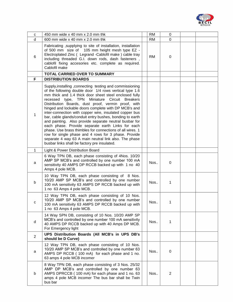
c 450 mm wide x 40 mm x 2.0 mm thk
RM 0
d 600 mm wide x 40 mm x 2.0 mm thk
RM 0
6
Fabricating ,supplying to site of installation, installation of 500 mm size of 105 mm height mesh type EZ -Electroplated Zinc ( Legrand -Cablofil make ) cable tray including threaded G.I. down rods, dash fasteners , cablofil fixing accesories etc. complete as required. Cablofil make
RM 0
TOTAL CARRIED OVER TO SUMMARY
F DISTRIBUTION BOARDS
1
Supply,installing ,connecting testing and commissioning of the following double door 1/4 rows vertical type 1.6 mm thick and 1.4 thick door sheet steel enclosed fully recessed type, TPN Miniature Circuit Breakers Distribution Boards, dust proof, vermin proof, with hinged and lockable doors complete with DP MCB's and inter-connection with copper wire, insulated copper bus bar, cable glands/conduit entry bushes, bonding to earth and painting. Also provide separate neutral busbar for each phase. Provide separate earth Links for each phase. Use brass thimbles for connections of all wires. 1 row for single phase and 4 rows for 3 phase. Provide separate 4 way 63 A main neutral link also. The phase busbar links shall be factory pre insulated.
1 Light & Power Distribution Board
a
6 Way TPN DB, each phase consisting of 4Nos. 10/20 AMP SP MCB‟s and controlled by one number 100 mA sensitivity 40 AMPS DP RCCB backed up with 1 no 40 Amps 4 pole MCB.
Nos.. 0
b
10 Way TPN DB, each phase consisting of 8 Nos. 10/20 AMP SP MCB‟s and controlled by one number 100 mA sensitivity 63 AMPS DP RCCB backed up with 1 no 63 Amps 4 pole MCB.
Nos.. 1
c
12 Way TPN DB, each phase consisting of 10 Nos. 10/20 AMP SP MCB‟s and controlled by one number 100 mA sensitivity 63 AMPS DP RCCB backed up with 1 no 63 Amps 4 pole MCB.
Nos.. 1
d
14 Way SPN DB, consisting of 10 Nos. 10/20 AMP SP MCB‟s and controlled by one number 100 mA sensitivity 40 AMPS DP RCCB backed up with 40 Amps DP MCB. For Emergency light
Nos.. 1
2 UPS Distribution Boards (All MCB's in UPS DB's should be D Curve)
a
12 Way TPN DB, each phase consisting of 10 Nos. 10/20 AMP SP MCB‟s and controlled by one number 63 AMPS DP RCCB ( 100 mA) for each phase and 1 no. 63 amps 4 pole MCB incomer
Nos.. 0
b
8 Way TPN DB, each phase consisting of 3 Nos. 25/32 AMP DP MCB‟s and controlled by one number 63 AMPS DPRCCB ( 100 mA) for each phase and 1 no. 63 amps 4 pole MCB incomer The bus bar shall be Twin bus bar
Nos.. 2
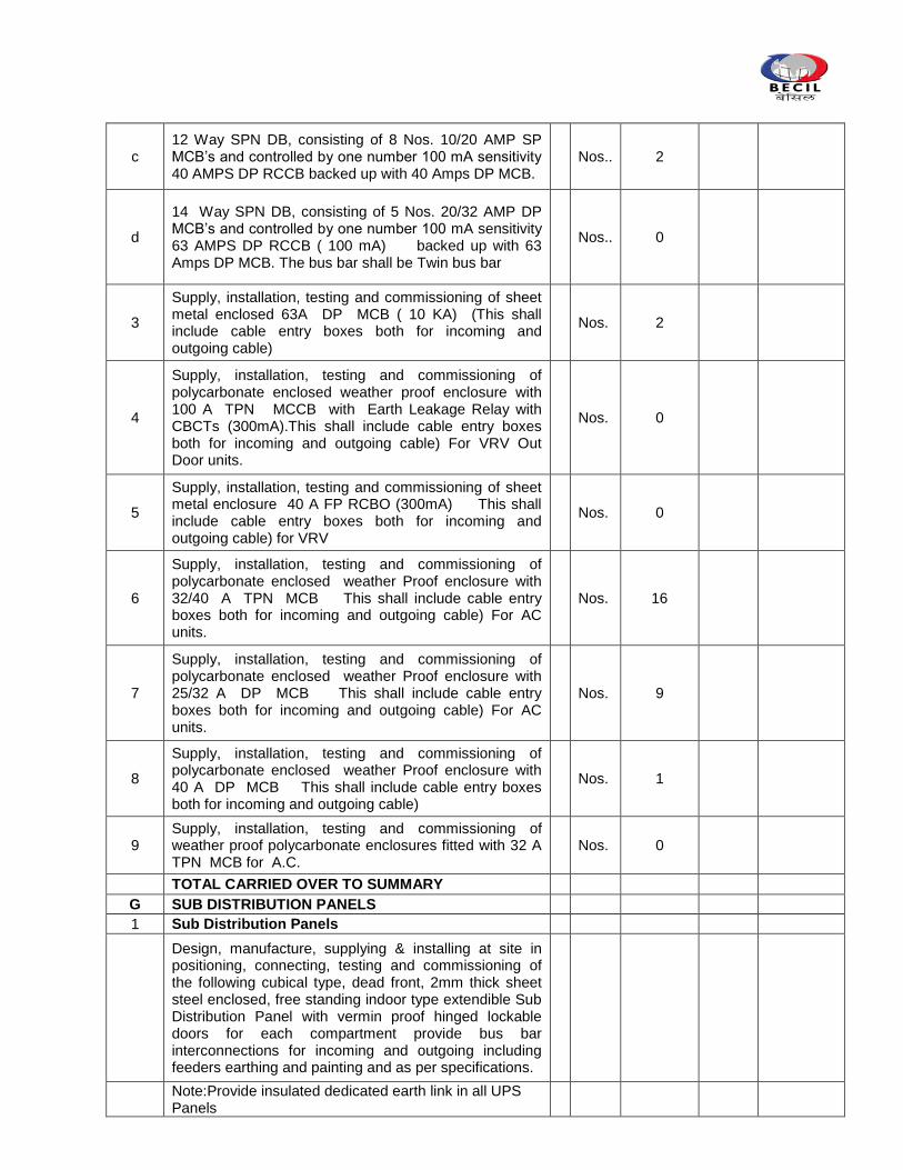
c 12 Way SPN DB, consisting of 8 Nos. 10/20 AMP SP MCB‟s and controlled by one number 100 mA sensitivity 40 AMPS DP RCCB backed up with 40 Amps DP MCB.
Nos.. 2
d
14 Way SPN DB, consisting of 5 Nos. 20/32 AMP DP MCB‟s and controlled by one number 100 mA sensitivity 63 AMPS DP RCCB ( 100 mA) backed up with 63 Amps DP MCB. The bus bar shall be Twin bus bar
Nos.. 0
3
Supply, installation, testing and commissioning of sheet metal enclosed 63A DP MCB ( 10 KA) (This shall include cable entry boxes both for incoming and outgoing cable)
Nos. 2
4
Supply, installation, testing and commissioning of polycarbonate enclosed weather proof enclosure with 100 A TPN MCCB with Earth Leakage Relay with CBCTs (300mA).This shall include cable entry boxes both for incoming and outgoing cable) For VRV Out Door units.
Nos. 0
5
Supply, installation, testing and commissioning of sheet metal enclosure 40 A FP RCBO (300mA) This shall include cable entry boxes both for incoming and outgoing cable) for VRV
Nos. 0
6
Supply, installation, testing and commissioning of polycarbonate enclosed weather Proof enclosure with 32/40 A TPN MCB This shall include cable entry boxes both for incoming and outgoing cable) For AC units.
Nos. 16
7
Supply, installation, testing and commissioning of polycarbonate enclosed weather Proof enclosure with 25/32 A DP MCB This shall include cable entry boxes both for incoming and outgoing cable) For AC units.
Nos. 9
8
Supply, installation, testing and commissioning of polycarbonate enclosed weather Proof enclosure with 40 A DP MCB This shall include cable entry boxes both for incoming and outgoing cable)
Nos. 1
9 Supply, installation, testing and commissioning of weather proof polycarbonate enclosures fitted with 32 A TPN MCB for A.C.
Nos. 0
TOTAL CARRIED OVER TO SUMMARY
G SUB DISTRIBUTION PANELS
1 Sub Distribution Panels
Design, manufacture, supplying & installing at site in positioning, connecting, testing and commissioning of the following cubical type, dead front, 2mm thick sheet steel enclosed, free standing indoor type extendible Sub Distribution Panel with vermin proof hinged lockable doors for each compartment provide bus bar interconnections for incoming and outgoing including feeders earthing and painting and as per specifications.
Note:Provide insulated dedicated earth link in all UPS Panels
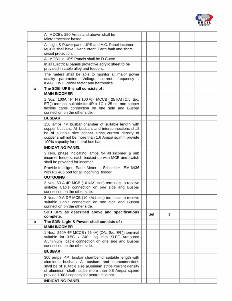
All MCCB's 250 Amps and above shall be Microprocessor based
All Light & Power panel,UPS and A.C. Panel incomer MCCB shall have Over current, Earth fault and short circuit protection.
All MCB's in UPS Panels shall be D Curve
In all Electrical panels protective acrylic sheet to be provided in cable alley and feeders.
The meters shall be able to monitor all major power quality parameters Voltage, current, frequency , KVAH,KWH,Power factor and harmonics.
a The SDB- UPS- shall consists of :
MAIN INCOMER
1 Nos. 100A TP N ( 100 %) MCCB ( 25 kA) (O/c, S/c, E/f )) terminal suitable for 4R x 1C x 25 sq. mm copper flexible cable connection on one side and Busbar connection on the other side.
BUSBAR
150 amps 4P busbar chamber of suitable length with copper busbars. All busbars and interconnections shall be of suitable size copper strips current density of copper shall not be more than 1.6 Amps/ sq.mm provide 100% capacity for neutral bus bar.
INDICATING PANEL
3 Nos. phase indicating lamps for all incomer & sub incomer feeders, each backed up with MCB and switch shall be provided for incomer.
Provide Intelligent Panel Meter - Schneider EM 6436 with RS 485 port for all incoming feeder
OUTGOING
3 Nos. 63 A 4P MCB (10 kA/1 sec) terminals to receive suitable Cable connection on one side and Busbar connection on the other side.
3 Nos. 40 A DP MCB (10 kA/1 sec) terminals to receive suitable Cable connection on one side and Busbar connection on the other side.
SDB UPS as described above and specifications complete.
Set 1
b The SDB- Light & Power- shall consists of :
MAIN INCOMER
1 Nos. 250A 4P MCCB ( 25 kA) (O/c, S/c, E/f )) terminal suitable for 3.5C x 240 sq. mm XLPE Armoured Aluminium cable connection on one side and Busbar connection on the other side.
BUSBAR
300 amps 4P busbar chamber of suitable length with aluminum busbars. All busbars and interconnections shall be of suitable size aluminum strips current density of aluminum shall not be more than 0.8 Amps/ sq.mm provide 100% capacity for neutral bus bar.
INDICATING PANEL
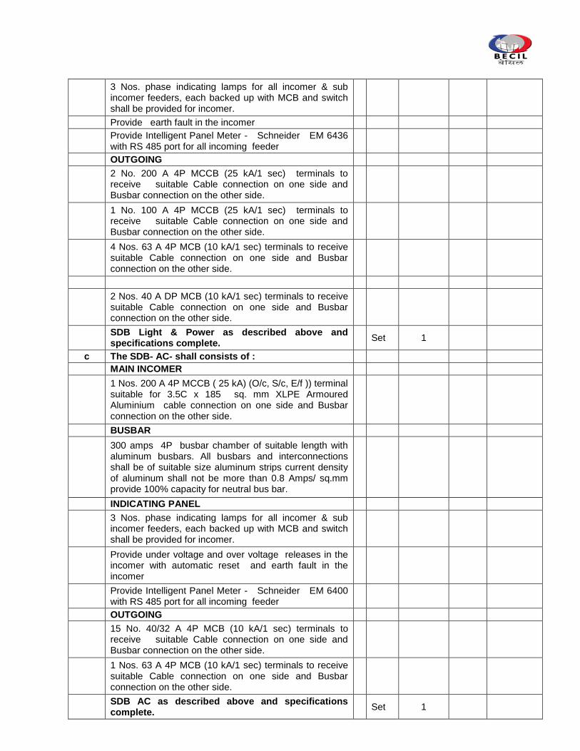
3 Nos. phase indicating lamps for all incomer & sub incomer feeders, each backed up with MCB and switch shall be provided for incomer.
Provide earth fault in the incomer
Provide Intelligent Panel Meter - Schneider EM 6436 with RS 485 port for all incoming feeder
OUTGOING
2 No. 200 A 4P MCCB (25 kA/1 sec) terminals to receive suitable Cable connection on one side and Busbar connection on the other side.
1 No. 100 A 4P MCCB (25 kA/1 sec) terminals to receive suitable Cable connection on one side and Busbar connection on the other side.
4 Nos. 63 A 4P MCB (10 kA/1 sec) terminals to receive suitable Cable connection on one side and Busbar connection on the other side.
2 Nos. 40 A DP MCB (10 kA/1 sec) terminals to receive suitable Cable connection on one side and Busbar connection on the other side.
SDB Light & Power as described above and specifications complete.
Set 1
c The SDB- AC- shall consists of :
MAIN INCOMER
1 Nos. 200 A 4P MCCB ( 25 kA) (O/c, S/c, E/f )) terminal suitable for 3.5C x 185 sq. mm XLPE Armoured Aluminium cable connection on one side and Busbar connection on the other side.
BUSBAR
300 amps 4P busbar chamber of suitable length with aluminum busbars. All busbars and interconnections shall be of suitable size aluminum strips current density of aluminum shall not be more than 0.8 Amps/ sq.mm provide 100% capacity for neutral bus bar.
INDICATING PANEL
3 Nos. phase indicating lamps for all incomer & sub incomer feeders, each backed up with MCB and switch shall be provided for incomer.
Provide under voltage and over voltage releases in the incomer with automatic reset and earth fault in the incomer
Provide Intelligent Panel Meter - Schneider EM 6400 with RS 485 port for all incoming feeder
OUTGOING
15 No. 40/32 A 4P MCB (10 kA/1 sec) terminals to receive suitable Cable connection on one side and Busbar connection on the other side.
1 Nos. 63 A 4P MCB (10 kA/1 sec) terminals to receive suitable Cable connection on one side and Busbar connection on the other side.
SDB AC as described above and specifications complete.
Set 1
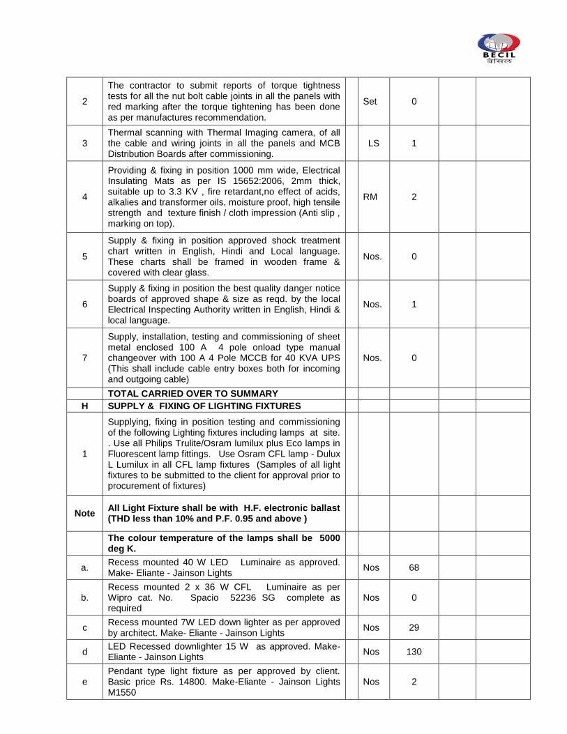
2
The contractor to submit reports of torque tightness tests for all the nut bolt cable joints in all the panels with red marking after the torque tightening has been done as per manufactures recommendation.
Set 0
3 Thermal scanning with Thermal Imaging camera, of all the cable and wiring joints in all the panels and MCB Distribution Boards after commissioning.
LS 1
4
Providing & fixing in position 1000 mm wide, Electrical Insulating Mats as per IS 15652:2006, 2mm thick, suitable up to 3.3 KV , fire retardant,no effect of acids, alkalies and transformer oils, moisture proof, high tensile strength and texture finish / cloth impression (Anti slip , marking on top).
RM 2
5
Supply & fixing in position approved shock treatment chart written in English, Hindi and Local language. These charts shall be framed in wooden frame & covered with clear glass.
Nos. 0
6
Supply & fixing in position the best quality danger notice boards of approved shape & size as reqd. by the local Electrical Inspecting Authority written in English, Hindi & local language.
Nos. 1
7
Supply, installation, testing and commissioning of sheet metal enclosed 100 A 4 pole onload type manual changeover with 100 A 4 Pole MCCB for 40 KVA UPS (This shall include cable entry boxes both for incoming and outgoing cable)
Nos. 0
TOTAL CARRIED OVER TO SUMMARY
H SUPPLY & FIXING OF LIGHTING FIXTURES
1
Supplying, fixing in position testing and commissioning of the following Lighting fixtures including lamps at site. . Use all Philips Trulite/Osram lumilux plus Eco lamps in Fluorescent lamp fittings. Use Osram CFL lamp - Dulux L Lumilux in all CFL lamp fixtures (Samples of all light fixtures to be submitted to the client for approval prior to procurement of fixtures)
Note All Light Fixture shall be with H.F. electronic ballast (THD less than 10% and P.F. 0.95 and above )
The colour temperature of the lamps shall be 5000 deg K.
a. Recess mounted 40 W LED Luminaire as approved. Make- Eliante - Jainson Lights
Nos 68
b. Recess mounted 2 x 36 W CFL Luminaire as per Wipro cat. No. Spacio 52236 SG complete as required
Nos 0
c Recess mounted 7W LED down lighter as per approved by architect. Make- Eliante - Jainson Lights
Nos 29
d LED Recessed downlighter 15 W as approved. Make-Eliante - Jainson Lights
Nos 130
e Pendant type light fixture as per approved by client. Basic price Rs. 14800. Make-Eliante - Jainson Lights M1550
Nos 2
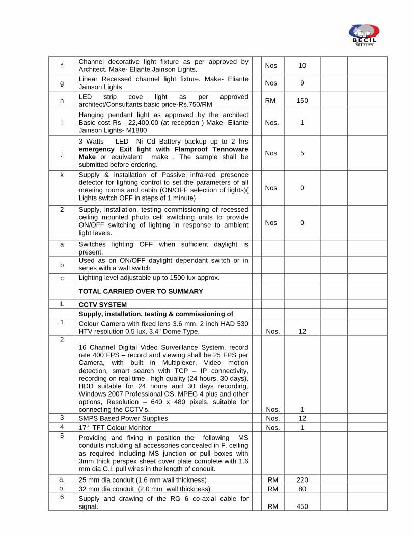
f Channel decorative light fixture as per approved by Architect. Make- Eliante Jainson Lights.
Nos 10
g Linear Recessed channel light fixture. Make- Eliante Jainson Lights
Nos 9
h LED strip cove light as per approved architect/Consultants basic price-Rs.750/RM
RM 150
i Hanging pendant light as approved by the architect Basic cost Rs - 22,400.00 (at reception ) Make- Eliante Jainson Lights- M1880
Nos. 1
j
3 Watts LED Ni Cd Battery backup up to 2 hrs emergency Exit light with Flamproof Tennoware Make or equivalent make . The sample shall be submitted before ordering.
Nos 5
k Supply & installation of Passive infra-red presence detector for lighting control to set the parameters of all meeting rooms and cabin (ON/OFF selection of lights)( Lights switch OFF in steps of 1 minute)
Nos 0
2 Supply, installation, testing commissioning of recessed ceiling mounted photo cell switching units to provide ON/OFF switching of lighting in response to ambient light levels.
Nos 0
a Switches lighting OFF when sufficient daylight is present.
b Used as on ON/OFF daylight dependant switch or in series with a wall switch
c Lighting level adjustable up to 1500 lux approx.
TOTAL CARRIED OVER TO SUMMARY
I. CCTV SYSTEM Supply, installation, testing & commissioning of 1 Colour Camera with fixed lens 3.6 mm, 2 inch HAD 530
HTV resolution 0.5 lux, 3.4" Dome Type.
Nos. 12
2 16 Channel Digital Video Surveillance System, record rate 400 FPS – record and viewing shall be 25 FPS per Camera, with built in Multiplexer, Video motion detection, smart search with TCP – IP connectivity, recording on real time , high quality (24 hours, 30 days), HDD suitable for 24 hours and 30 days recording, Windows 2007 Professional OS, MPEG 4 plus and other options, Resolution – 640 x 480 pixels, suitable for connecting the CCTV‟s.
Nos. 1
3 SMPS Based Power Supplies
Nos. 12
4 17" TFT Colour Monitor
Nos. 1
5 Providing and fixing in position the following MS conduits including all accessories concealed in F. ceiling as required including MS junction or pull boxes with 3mm thick perspex sheet cover plate complete with 1.6 mm dia G.I. pull wires in the length of conduit.
a. 25 mm dia conduit (1.6 mm wall thickness)
RM 220
b. 32 mm dia conduit (2.0 mm wall thickness)
RM 80
6 Supply and drawing of the RG 6 co-axial cable for
signal.
RM 450
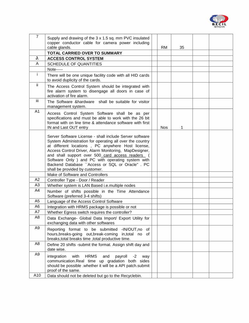
7 Supply and drawing of the 3 x 1.5 sq. mm PVC insulated copper conductor cable for camera power including cable glands.
RM 35
TOTAL CARRIED OVER TO SUMMARY
J. ACCESS CONTROL SYSTEM A SCHEDULE OF QUANTITIES Note----- i There will be one unique facility code with all HID cards
to avoid duplicity of the cards. ii The Access Control System should be integrated with
fire alarm system to disengage all doors in case of activation of fire alarm.
iii The Software &hardware shall be suitable for visitor management system.
A1 Access Control System Software shall be as per specifications and must be able to work with the 26 bit format with on line time & attendance software with first IN and Last OUT entry
Nos 1
Server Software License - shall include Server software System Administration for operating all over the country at different locations , PC anywhere Host license, Access Control Driver, Alarm Monitoring, MapDesigner, and shall support over 500 card access readers ( Software Only ) and PC with operating system with Backend Database ``Access or SQL or Oracle'' . PC shall be provided by customer.
Make of Software and Controllers A2 Controller Type - Door / Reader A3 Whether system is LAN Based i.e.multiple nodes A4 Number of shifts possible in the Time Attendance
Software (preferred 3-4 shifts) A5 Language of the Access Control Software A6 Integration with HRMS package is possible or not A7 Whether Egress switch requires the controller? A8 Data Exchange- Global Data Import/ Export Utility for
exchanging data with other softwares A9 Reporting format to be submitted -IN/OUT,no of
hours,breaks-going out,break-coming in,total no of breaks,total breaks time ,total productive time.
A8 Define 20 shifts -submit the format. Assign shift day and date wise.
A9 integration with HRMS and payroll -2 way communication.Real time up gradation both sides should be possible .whether it will be a API patch.submit proof of the same.
A10 Data should not be deleted but go to the Recyclebin.
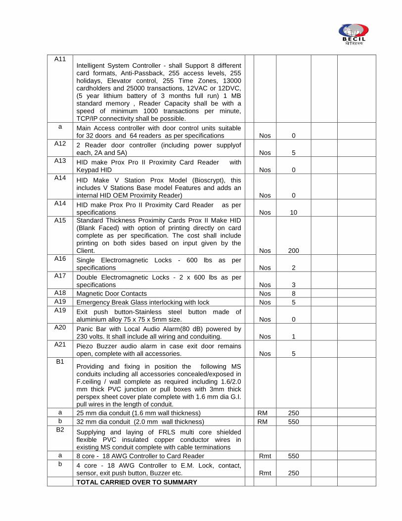
A11 Intelligent System Controller - shall Support 8 different card formats, Anti-Passback, 255 access levels, 255 holidays, Elevator control, 255 Time Zones, 13000 cardholders and 25000 transactions, 12VAC or 12DVC, (5 year lithium battery of 3 months full run) 1 MB standard memory , Reader Capacity shall be with a speed of minimum 1000 transactions per minute, TCP/IP connectivity shall be possible.
a Main Access controller with door control units suitable for 32 doors and 64 readers as per specifications
Nos 0
A12 2 Reader door controller (including power supplyof each, 2A and 5A)
Nos 5
A13 HID make Prox Pro II Proximity Card Reader with Keypad HID
Nos 0
A14 HID Make V Station Prox Model (Bioscrypt), this includes V Stations Base model Features and adds an internal HID OEM Proximity Reader)
Nos 0
A14 HID make Prox Pro II Proximity Card Reader as per specifications
Nos 10
A15 Standard Thickness Proximity Cards Prox II Make HID (Blank Faced) with option of printing directly on card complete as per specification. The cost shall include printing on both sides based on input given by the Client.
Nos 200
A16 Single Electromagnetic Locks - 600 lbs as per specifications
Nos 2
A17 Double Electromagnetic Locks - 2 x 600 lbs as per specifications
Nos 3
A18 Magnetic Door Contacts
Nos 8
A19 Emergency Break Glass interlocking with lock
Nos 5
A19 Exit push button-Stainless steel button made of aluminium alloy 75 x 75 x 5mm size.
Nos 0
A20 Panic Bar with Local Audio Alarm(80 dB) powered by 230 volts. It shall include all wiring and conduiting.
Nos 1
A21 Piezo Buzzer audio alarm in case exit door remains open, complete with all accessories.
Nos 5
B1 Providing and fixing in position the following MS conduits including all accessories concealed/exposed in F.ceiling / wall complete as required including 1.6/2.0 mm thick PVC junction or pull boxes with 3mm thick perspex sheet cover plate complete with 1.6 mm dia G.I. pull wires in the length of conduit.
a 25 mm dia conduit (1.6 mm wall thickness)
RM 250
b 32 mm dia conduit (2.0 mm wall thickness)
RM 550
B2 Supplying and laying of FRLS multi core shielded flexible PVC insulated copper conductor wires in existing MS conduit complete with cable terminations
a 8 core - 18 AWG Controller to Card Reader
Rmt 550
b 4 core - 18 AWG Controller to E.M. Lock, contact,
sensor, exit push button, Buzzer etc.
Rmt 250
TOTAL CARRIED OVER TO SUMMARY
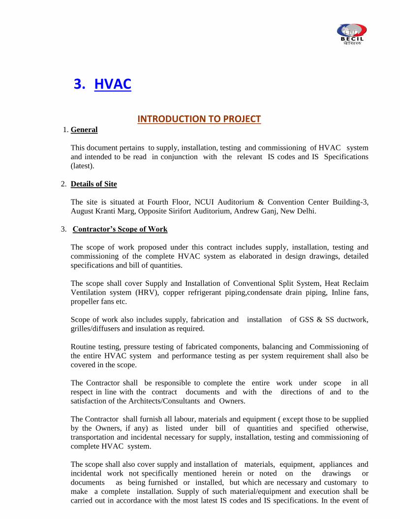
3. HVAC
INTRODUCTION TO PROJECT 1. General
This document pertains to supply, installation, testing and commissioning of HVAC system
and intended to be read in conjunction with the relevant IS codes and IS Specifications
(latest).
2. Details of Site
The site is situated at Fourth Floor, NCUI Auditorium & Convention Center Building-3,
August Kranti Marg, Opposite Sirifort Auditorium, Andrew Ganj, New Delhi.
3. Contractor’s Scope of Work
The scope of work proposed under this contract includes supply, installation, testing and
commissioning of the complete HVAC system as elaborated in design drawings, detailed
specifications and bill of quantities.
The scope shall cover Supply and Installation of Conventional Split System, Heat Reclaim
Ventilation system (HRV), copper refrigerant piping,condensate drain piping, Inline fans,
propeller fans etc.
Scope of work also includes supply, fabrication and installation of GSS & SS ductwork,
grilles/diffusers and insulation as required.
Routine testing, pressure testing of fabricated components, balancing and Commissioning of
the entire HVAC system and performance testing as per system requirement shall also be
covered in the scope.
The Contractor shall be responsible to complete the entire work under scope in all
respect in line with the contract documents and with the directions of and to the
satisfaction of the Architects/Consultants and Owners.
The Contractor shall furnish all labour, materials and equipment ( except those to be supplied
by the Owners, if any) as listed under bill of quantities and specified otherwise,
transportation and incidental necessary for supply, installation, testing and commissioning of
complete HVAC system.
The scope shall also cover supply and installation of materials, equipment, appliances and
incidental work not specifically mentioned herein or noted on the drawings or
documents as being furnished or installed, but which are necessary and customary to
make a complete installation. Supply of such material/equipment and execution shall be
carried out in accordance with the most latest IS codes and IS specifications. In the event of
non availability of relevant IS codes/specifications, good engineering practices shall be
adopted.
4. Items to be provided by other agencies:
The following activities associated with the said contract shall be carried out by other
agencies under direct supervision of the AC contractor:
4.1 Civil Works:
All associated civil works listed below shall be carried out by civil /interior contractor:
Providing opening in walls/slabs for crossing of ducts/piping and making
them good & finished.
4.1.2 Plumbing Works:
All associated plumbing works listed below shall be carried out by plumbing contractor.
a. Providing floor trap for termination of condensate drain piping associated with AC
indoor units to be carried out by the AC contractor.
4.1.3. Electrical Works:
All associated electrical works listed below shall be carried out by electrical contractor:
a. Providing 415 + 10 % volts, 50 Hz, 3 phases stabilised power supply at control panel
ofductable split unit in the form of power cabling and necessary earthing.
b. Providing 220 + 6 % volts, 50 Hz, 1 phase power point near each non ductable split unit,
HRV Unit, propeller fan and inline fans for toilet /pantry exhaust as shown in the design
drawings.
*****************************
SYSTEM DESIGN
1.0 Introduction:
An air-conditioning system using ductable/non ductable split units is being designed for office
spaces for the proposed office spaces for WDRA office at New Delhi.
The design being proposed also envisages mechanical ventilation system for toilets, pantry
and other similar spaces.
.
2.0 Basis of Design:
The various design parameters pertaining to air-conditioning system are being given
hereunder:
a. Orientation:
Orientation of the building is as noted during site visit.
b. Outside design conditions :
The outside design conditions for New Delhi are given hereunder:
Season Dry Bulb Temperature Wet Bulb Temperature
Summer 110 F (43.3 C) db 75 F (23.9 C) wb
Monsoon 95 F (35 C) db 83 F (28.3 C) wb
Winter 45 F ( 7.2 C) db 41 F ( 5 C) wb
c. Inside design conditions :
Summer & Monsoon:
i. For Office Spaces
Temperature : 73.4+ 2 F (23+1C)
Relative Humidity : Not to exceed 65% during monsoon
ii. For Server Room
Temperature : 71.6+ 2 F (22+1C)
Relative Humidity : Not to exceed 65% during monsoon
iii. For UPS Room & Battery Room
Temperature : 75.2+ 2º F (24+1º C)
Relative Humidity : Not to exceed 65% during monsoon
d. External Building Fabric detail :
The following details as regard to heat gain from external building fabric have been
considered which are subject to further confirmation from Developers:
i. For Double Glass :
Solar Factor: 0.58 (with venetian blinds)
Overall Heat Transfer Co-efficient (“U” Value): 0.32 BTUs/Hr Sft F
(1.8 Watt/SqM K)
ii. For Walls (230mm Brick Wall):
Overall Heat Transfer Co-efficient (“U” Value) : 0.32 BTUs/Hr Sft F
(1.82 Watt/SqM K)
e. Relevant International Codes and Standards:
Apart from the specific equipment standards and specifications, the following broad
certifying agency/standards will be considered while designing the system:
i. ASHRAE -American Society for Heating, Refrigerating and Air-conditioning
Engineers –ASHRAE1992 Edition.
ii. SMACNA – Sheet Metal and Air Conditioning Contractors National Association.
iii. UL - Underwriter‟s Laboratory, USA.
iv. ANSI - American National Standards Institute
v. NEMA - National Electrical Manufacturers Association
vi. ETL - Electrical Testing Laboratories
vii. NEC - National Electrical Code
viii. NFC - National Fire Code
ix. ISO - International Standards Organization
f. Fresh air replenishment:
Generally as per ASHRAE Standard 62.1 – 2010 recommendatio
g. Design Data:
Space Floor
Area
(Sft)
Height
(Ft)
Occupancy
(Persons)
Lighting
Load**
(Watt/
Sft)
Equipment
Load
(KW)
Applianc
es*
(Sft)
Fresh
Air
(Cfm)
Hours of
operation
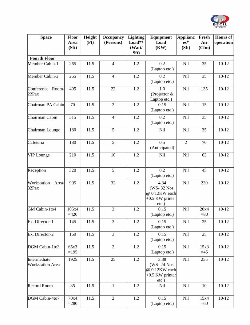
Space Floor
Area
(Sft)
Height
(Ft)
Occupancy
(Persons)
Lighting
Load**
(Watt/
Sft)
Equipment
Load
(KW)
Applianc
es*
(Sft)
Fresh
Air
(Cfm)
Hours of
operation
Fourth Floor
Member Cabin-1 265 11.5 4 1.2 0.2
(Laptop etc.)
Nil 35 10-12
Member Cabin-2 265 11.5 4 1.2 0.2
(Laptop etc.)
Nil 35 10-12
Conference Room-
22Pax
405 11.5 22 1.2 1.0
(Projector &
Laptop etc.)
Nil 135 10-12
Chairman PA Cabin 70 11.5 2 1.2 0.15
(Laptop etc.)
Nil 15 10-12
Chairman Cabin 315 11.5 4 1.2 0.2
(Laptop etc.)
Nil 35 10-12
Chairman Lounge 180 11.5 5 1.2 Nil Nil 35 10-12
Cafeteria 180 11.5 5 1.2 0.5
(Anticipated)
2 70 10-12
VIP Lounge 210 11.5 10 1.2 Nil Nil 63 10-12
Reception 320 11.5 5 1.2 0.2
(Laptop etc.)
Nil 45 10-12
Workstation Area-
32Pax
995 11.5 32 1.2 4.34
(WS- 32 Nos.
@ 0.12KW each
+0.5 KW printer
etc.)
Nil 220 10-12
GM Cabin-1to4 105x4
=420
11.5 3 1.2 0.15
(Laptop etc.)
Nil 20x4
=80
10-12
Ex. Director-1 145 11.5 3 1.2 0.15
(Laptop etc.)
Nil 25
10-12
Ex. Director-2 160 11.5 3 1.2 0.15
(Laptop etc.)
Nil 25
10-12
DGM Cabin-1to3 65x3
=195
11.5 2 1.2 0.15
(Laptop etc.)
Nil 15x3
=45
10-12
Intermediate
Workstation Area
1925 11.5 25 1.2 3.38
(WS- 24 Nos.
@ 0.12KW each
+0.5 KW printer
etc.)
Nil 255 10-12
Record Room 85 11.5 1 1.2 Nil Nil 10 10-12
DGM Cabin-4to7 70x4
=280
11.5 2 1.2 0.15
(Laptop etc.)
Nil 15x4
=60
10-12
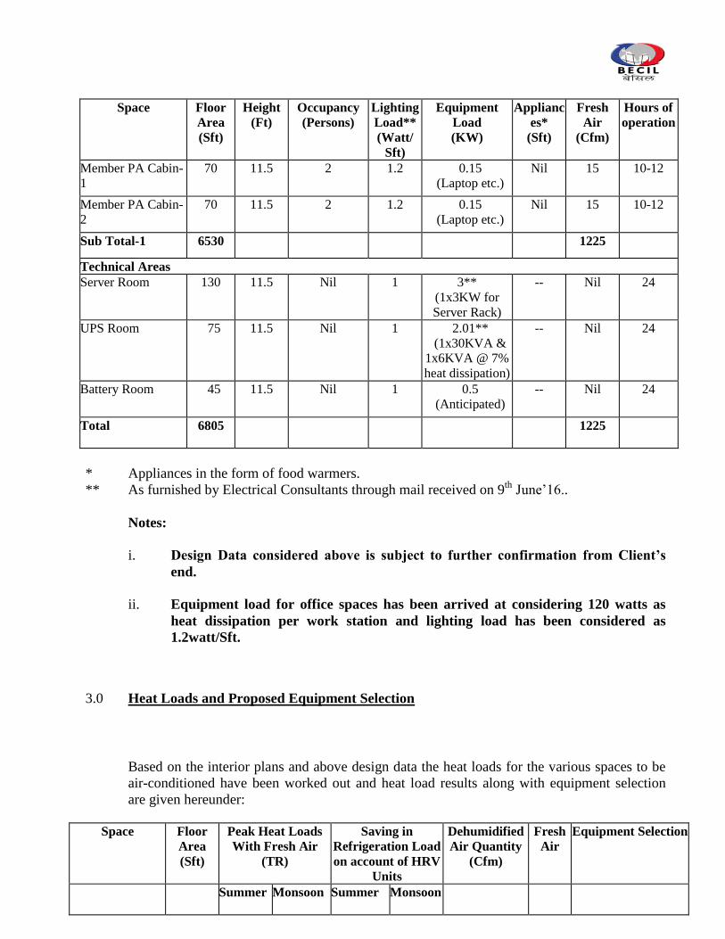
Space Floor
Area
(Sft)
Height
(Ft)
Occupancy
(Persons)
Lighting
Load**
(Watt/
Sft)
Equipment
Load
(KW)
Applianc
es*
(Sft)
Fresh
Air
(Cfm)
Hours of
operation
Member PA Cabin-
1
70 11.5 2 1.2 0.15
(Laptop etc.)
Nil 15 10-12
Member PA Cabin-
2
70 11.5 2 1.2 0.15
(Laptop etc.)
Nil 15 10-12
Sub Total-1 6530 1225
Technical Areas
Server Room 130 11.5 Nil 1 3**
(1x3KW for
Server Rack)
-- Nil 24
UPS Room 75 11.5 Nil 1 2.01**
(1x30KVA &
1x6KVA @ 7%
heat dissipation)
-- Nil 24
Battery Room 45 11.5 Nil 1 0.5
(Anticipated)
-- Nil 24
Total 6805 1225
* Appliances in the form of food warmers.
** As furnished by Electrical Consultants through mail received on 9th
June‟16..
Notes:
i. Design Data considered above is subject to further confirmation from Client’s
end.
ii. Equipment load for office spaces has been arrived at considering 120 watts as
heat dissipation per work station and lighting load has been considered as
1.2watt/Sft.
3.0 Heat Loads and Proposed Equipment Selection
Based on the interior plans and above design data the heat loads for the various spaces to be
air-conditioned have been worked out and heat load results along with equipment selection
are given hereunder:
Space Floor
Area
(Sft)
Peak Heat Loads
With Fresh Air
(TR)
Saving in
Refrigeration Load
on account of HRV
Units
Dehumidified
Air Quantity
(Cfm)
Fresh
Air
Equipment Selection
Summer Monsoon
Summer Monsoon
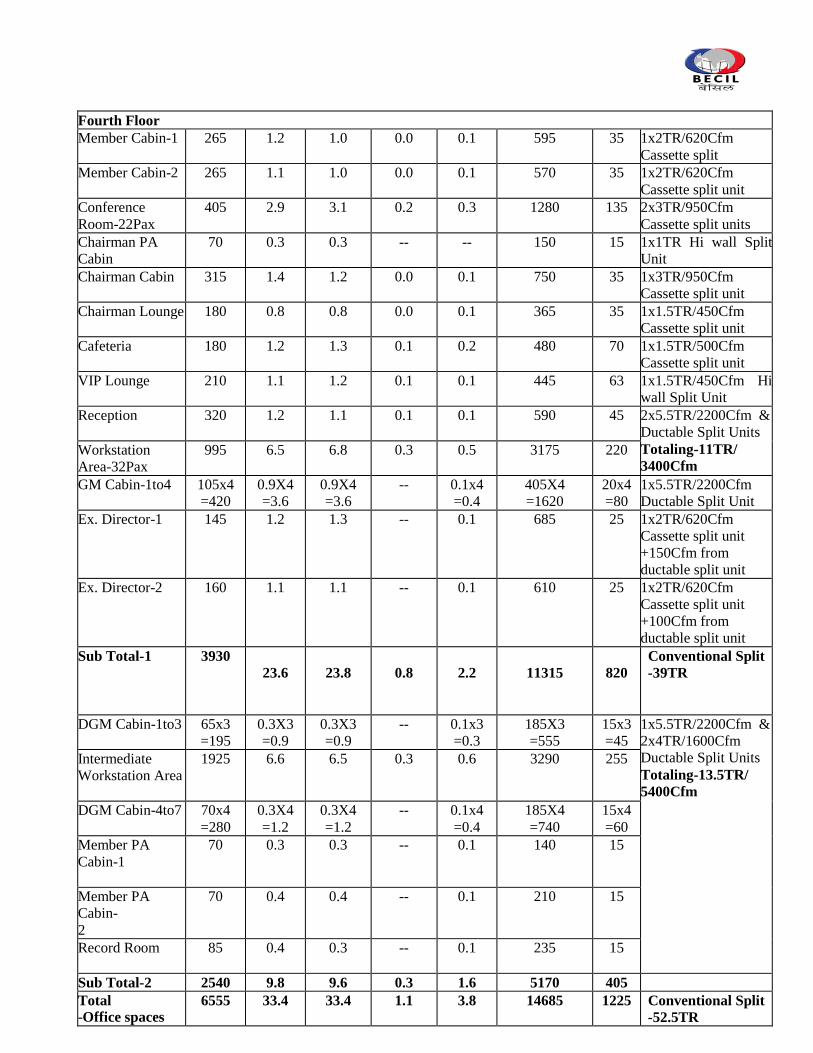
Fourth Floor
Member Cabin-1
265 1.2 1.0 0.0 0.1 595 35 1x2TR/620Cfm
Cassette split
Member Cabin-2
265 1.1 1.0 0.0 0.1 570 35 1x2TR/620Cfm
Cassette split unit
Conference
Room-22Pax
405 2.9 3.1 0.2 0.3 1280 135 2x3TR/950Cfm
Cassette split units
Chairman PA
Cabin
70
0.3 0.3 -- -- 150 15 1x1TR Hi wall Split
Unit
Chairman Cabin
315 1.4 1.2 0.0 0.1 750 35 1x3TR/950Cfm
Cassette split unit
Chairman Lounge
180 0.8 0.8 0.0 0.1 365 35 1x1.5TR/450Cfm
Cassette split unit
Cafeteria
180 1.2 1.3 0.1 0.2 480 70 1x1.5TR/500Cfm
Cassette split unit
VIP Lounge
210 1.1 1.2 0.1 0.1 445 63 1x1.5TR/450Cfm Hi
wall Split Unit
Reception
320 1.2 1.1 0.1 0.1 590 45 2x5.5TR/2200Cfm &
Ductable Split Units
Totaling-11TR/
3400Cfm Workstation
Area-32Pax
995 6.5 6.8 0.3 0.5 3175 220
GM Cabin-1to4 105x4
=420
0.9X4
=3.6
0.9X4
=3.6
-- 0.1x4
=0.4
405X4
=1620
20x4
=80
1x5.5TR/2200Cfm
Ductable Split Unit
Ex. Director-1
145 1.2 1.3 -- 0.1 685 25
1x2TR/620Cfm
Cassette split unit
+150Cfm from
ductable split unit
Ex. Director-2
160 1.1 1.1 -- 0.1 610 25
1x2TR/620Cfm
Cassette split unit
+100Cfm from
ductable split unit
Sub Total-1 3930
23.6 23.8 0.8 2.2 11315 820
Conventional Split
-39TR
DGM Cabin-1to3 65x3
=195
0.3X3
=0.9
0.3X3
=0.9
-- 0.1x3
=0.3
185X3
=555
15x3
=45
1x5.5TR/2200Cfm &
2x4TR/1600Cfm
Ductable Split Units
Totaling-13.5TR/
5400Cfm
Intermediate
Workstation Area
1925 6.6 6.5 0.3 0.6 3290 255
DGM Cabin-4to7
70x4
=280
0.3X4
=1.2
0.3X4
=1.2
-- 0.1x4
=0.4
185X4
=740
15x4
=60
Member PA
Cabin-1
70 0.3 0.3 -- 0.1 140 15
Member PA
Cabin-
2
70 0.4 0.4 -- 0.1 210 15
Record Room
85 0.4 0.3 -- 0.1 235 15
Sub Total-2 2540 9.8 9.6 0.3 1.6 5170 405
Total
-Office spaces 6555 33.4 33.4 1.1 3.8 14685 1225 Conventional Split
-52.5TR
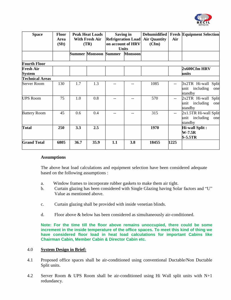
Space Floor
Area
(Sft)
Peak Heat Loads
With Fresh Air
(TR)
Saving in
Refrigeration Load
on account of HRV
Units
Dehumidified
Air Quantity
(Cfm)
Fresh
Air
Equipment Selection
Summer Monsoon
Summer Monsoon
Fourth Floor
Fresh Air
System
2x600Cfm HRV
units
Technical Areas
Server Room
130 1.7 1.3 -- -- 1085 -- 3x2TR Hi-wall Split
unit including one
standby
UPS Room
75 1.0 0.8 -- -- 570 -- 2x2TR Hi-wall Split
unit including one
standby
Battery Room
45 0.6 0.4 -- -- 315 -- 2x1.5TR Hi-wall Split
unit including one
standby
Total
250 3.3 2.5 1970 Hi-wall Split :
W-7.5R
S-5.5TR
Grand Total
6805 36.7 35.9 1.1 3.8 18455 1225
Assumptions
The above heat load calculations and equipment selection have been considered adequate
based on the following assumptions :
a. Window frames to incorporate rubber gaskets to make them air tight.
b. Curtain glazing has been considered with Single Glazing having Solar factors and “U”
Value as mentioned above.
c. Curtain glazing shall be provided with inside venetian blinds.
d. Floor above & below has been considered as simultaneously air-conditioned.
Note: For the time till the floor above remains unoccupied, there could be some increment in the inside temperature of the office spaces. To meet this kind of thing we have considered floor load in heat load calculations for important Cabins like Chairman Cabin, Member Cabin & Director Cabin etc.
4.0 System Design in Brief:
4.1 Proposed office spaces shall be air-conditioned using conventional Ductable/Non Ductable
Split units.
4.2 Server Room & UPS Room shall be air-conditioned using Hi Wall split units with N+1
redundancy.
4.3 Outdoor units shall be installed at Ground floor level and copper refrigerant piping to & from
outdoors shall run through shafts/cutouts with minimum refrigerant piping length.
4.4 Air distribution system shall comprise of GSS ductwork and extruded aluminium powder
coated grilles and diffusers. Supply air ducting shall run above false ceiling spaces. Return air
shall also travel up to air handling units from above the false ceiling spaces surrounding
supply air ductwork. Supply air ducting shall be acoustically and thermally insulated as
required.
4.5 Mechanical ventilation system shall be provided for toilets using inline fans and propeller
fans.
4.6 Associated electrical work shall comprise of panels, power cabling, control cabling and
necessary earthing.
5.0 Noise Level
Noise level in conditioned spaces due to all air conditioning equipment shall not exceed
52 dB at 125 Hz when measured at any point in occupied spaces less than 1500 mm
above finish floor level and not closer than 1500 mm from any supply air register or
600 mm from any return air grille.
***************************
CONDITIONS OF THE CONTRACT
1. Date of Commencement
Within 3 days from the date of award of work. If the contractor fails to start the work to
the satisfaction of Architect, his earnest money, if any will be forfeited.
2. Period of completion
i) The entire air conditioning works to be completed within2 (Two)Monthsfrom the date
of award of work.
ii) However, fabrication and installation of entire duct work and installation of copper
refrigerant piping has to be completed within 4 (Four) weeks from the date of
award of work. Entire work including testing and commissioning shall be completed
in all respects within 2 Months from the award of work.
3. Defects liability period.
One Year after the virtual completion of the work as certified by the Architect/
Consultant.
4. Liquidated damage
In the event of delays Liquidated Damages shall be charged by the owners from
the contractor as follows :
i) Ducting Work:
In the event of failure of the contractor to complete the fabrication and installation
of ductwork and Refrigerant piping, liquidated damages will be claimed @ Rs.
3000/- (Rupees Three Thousand Hundred) per day inclusive of Sundays and
holidays subject to a maximum of 5% of the contract value associated with air
distribution system and piping.
ii) Entire HVAC work:
In case the work as a whole is not completed with in stipulated period of 3 months
from date of start then the contractor will be liable to pay an amount equal to 1. 0 %
(one percent) of the total tendered amount per week of delay subject to a maximum of
10% of the total contract value.
5. Retention money
5 % (including earnest money, if any) to be deducted from each running bill subject to
maximum of Rs.1.75 lac ( Rupees One Lac & Seventy Five Thousand Only) out of which
50 % amount will be released after six months of virtual completion and rest 50 %
amount will be released after satisfactory completion of the defects liability period.
6. Terms of Payment
The following terms of Payment shall be adhered to :
i..10% as mobilization advance against a bank guarantee of equal amount valid till
completion of the project.
ii..5% against approval of all shop drawings and technical submittals.
iii..60% against delivery of equipment/material at site on pro rata basis.
iv..15% against erection of equipment /material on pro rata basis.
v.. 10% against satisfactory testing and commissioning of entire HVAC work and
submission & approval of “As Built Drawings and Completion Documents”.
7. Escalation
This being a firm offer, the contractor will not be entitled for any escalation. No
escalation/change of prices would be admissible under any circumstances.
8. Quantities
a) Quantities of items listed in schedule of Quantities may be increased, reduced or omitted
to any extent. Exact quantity of every item shall be measured and paid as per actual work
done at site.
b) The owner reserves the right to exclude any items from the scope of work of the main
contract and may appoint a sub- contractor for the work directly.
c) All tenders in which any of the prescribed conditions are not fulfilled are liable to be
rejected.
9. Taxes
The contractor shall bear the amount of income tax, sales tax, VAT, works contract tax,
service tax or any other tax octroi legally payable and it shall be assumed that his rates cover
for all taxes and duties and no claim on this account will be entertained unless and until
specified otherwise.
If the work contract tax as applicable on work at the time of award of work is increased /
decreased, the same will be reimbursable to/ recoverable from the contractor.
The Owner shall deduct taxes at source at the time of payment from the contractor‟s bill as
per prevailing laws. The tax shall be deducted on total work done (contract amount)
including the cost of material supplied by owner
10. PF and ESI Returns
Filing of provident fund and ESI Returns with concerned departments shall be the
responsibility of the contactor which shall be approved by the owner / Architect.
11. Extra item
The extra item rates shall either be derived from the tender item or substantiated by a detailed
rate analysis at market rates and to be got approved from the Architects/Consultants.
12.Engineering Responsibility of the system
The responsibility of system design, manufacturing, erection, working and safety will solely
be responsibility of the Contractor for the parameters as mentioned in the tender documents
prepared by the consulting engineers.
The system after commissioning shall be handed over to the Owners and
thereafter they will monitor the performance for standard designed parameters for 30 days
continuously. In case during this period the performance is not found satisfactory and
rectification/ replacement, design improvement or any other change is felt necessary, will be
made by the Contractor at no extra cost to the Owner. Though these
improvements can only be done after getting the approval from the Owners/Architects.
13. Liability to Govt. Regulations
The Contractor shall be responsible and shall abide by all the government rules and
regulations pertaining to erection, testing and commissioning of complete HVAC system at
site. Any compensation towards damage/loss of property/ material/equipment or to any person
working at site shall be borne by the Contractor as per standard terms of contract.
14. Store
A lockable storage space shall be provided by the Clients but safe custody shall be the responsibility
of the contractor till the installation is taken over.
15. Certificate of Inspection
The contractor shall obtain and deliver to the owner, a certificate of final inspection by the
local authorities concerned, if required at site. The inspection fee shall be reimbursed as per
actual on the production of receipt in original.
Further the Owners/Architects shall have full powers to order the materials or work to be tested by an independent agency at the Contractors expense in order to prove its fault & in-adequacy.
16. Design Drawings
The drawings prepared by the Consultants are indicative only of the general arrangement of
the entire installation. The Contractor shall follow these drawings and specifications in
preparation of his shop drawings and subsequent installation. He shall check the drawings of
other trades to verify space for his installation. The Contractor shall examine all relevant
architectural, structural, plumbing, electrical and other services layout drawings before
preparing the shop drawings for this installation, and report to the Architects/Consultants any
discrepancy and obtain clarifications. Any changes found necessary for co-ordination and
installation of this work with other services and trades shall be made with prior approval of
the Architects/Consultants and Owner without any additional cost to the Owner.
17. Site visit & Shop Drawings
The contractor shall visit the site and shall satisfy himself as to condition under which work is to be performed.
No claim for consequences of ignorance at the later date shall be entertained. He should also check and ascertain
the location of existing structure or equipment or any other situation which may affect the work.
The contractor shall submit five sets of shop drawings for air distribution system layout, Electrical panels &
Equipment Layout drawings for approval of the Owners/Architects. Contractor shall also submit technical
submittals for all major items including split units, ventilation fans, fresh air units, piping, GS sheet, grilles,
diffusers, fire dampers, insulation material, electrical components etc. for the approval of the Owners/Architects.
Five sets of detailed shop drawings of all equipment and materials including plant room,
ducting, piping, ventilation system, electrical work associated with the HVAC system
required to complete the project as per specifications and as required by the Architect/
Consultant. These drawings shall contain details of construction, size, arrangement, operating
clearances, performance characteristics and capacity of all equipment, also the details of all
related items of work by other Contractors. Each item of equipment proposed shall be a
standard catalogue product of an established manufacturer as per specifications.
If the Architect/Consultants makes any amendment in the above drawings, the contractor shall
supply two fresh sets of drawings with the amendments duly incorporated, along with the
drawings on which corrections were made. After final approval has been obtained from the
Architect/Consultant, the Contractor shall submit a further six sets of shop drawings for the
exclusive use of and retention by the Architect/Consultant. No material or equipment may
be delivered or installed at the job site until the contractor has in his possession, the
approved shop drawings for the particular material or equipment.
The shop drawings shall be submitted for approval sufficiently in advance of planned delivery
and installation of any material to allow Architects/ Consultants ample time for scrutiny. No
claims for extension of time shall be entertained because of any delay in the work due to his
failure to produce shop drawings at the right time, in accordance with the approved CPM
charts.
Samples, drawings, specifications, catalogues, pamphlets and other documents submitted for
approval shall be in quadruplicate, each item in each set shall be properly labeled, indicating the
specific service for which material or equipment is to be used, giving reference to the governing
section and clause number of Specifications clearly identifying in ink the items and the operating
characteristics. Data of a general nature shall not be accepted.
Approval rendered on shop drawings shall not be considered as a guarantee of measurements of
building conditions. Where drawings are approved, said approval does not mean that
drawings have been checked in detail nor does it any way relieve the Contractor from his
responsibility or necessity of furnishing material or performing work as required by the contract.
Where the Contractor proposes to use an item of equipment other than that specified or
detailed on the drawings which requires any redesign of the structure, partitions, foundations,
piping, wiring or any other part of the mechanical, electrical or architectural layout, all such
redesign and all new drawings and detailing required thereof, shall be prepared by the Contractor
at his own cost and approved by the Architect/Consultant.
Where the work of the Contractor has to be installed in close proximity to, or will interfere with
work of other trades, he shall assist in working out space conditions to make satisfactory
adjustments. If so directed by the Architect/Consultant, the Contractor shall prepare composite
working drawings and sections at a suitable scale not less than 1:50, clearly showing how his
work is to be installed in relation to the work of other trades. If the Contractor installs his work
before coordinating with other trades, or so as to cause any interference with work of other trades,
he shall make all the necessary changes without extra cost to the Owner.
Within two weeks of approval of all the relevant shop drawings, the Contractor shall submit to the
Architect/Consultant four copies of comprehensive itemized price list of recommended imported
and local spare parts and tools covering all equipment and materials in this contract. The Owner
shall make arrangements to procure these spare parts and tools.
18. Material & Workmanship
All material used in work shall be of the best quality, obtainable and of approved list of manufacturers and
shall conform to latest Indian Standard specifications unless otherwise stated.
19. Erection and Supervision
The Contractor shall depute engineers from time to time of commencement of installation work to inspect all
relevant foundation/fabrication and other necessary facilities to make improved action if felt
necessary. However, a qualified experienced engineer to be deputed at site beginning from
commencement of HVAC activities at site & till handing over of the prject.
20. Testing and Commissioning
On completion, the installation shall be tested for conformity with the stipulated performance
specifications. Any defect, shortcoming detected in the system/material/workmanship shall be
rectified by the Contractor to the entire satisfaction of the Consultants without any extra cost
to the Owner. The installation shall be tested again after the removal of the defects and shall
be commissioned only after approval by competent inspecting authority or the Consultants
and the Owner. All tests shall be carried out in the presence of the Consultants and Owner‟s
representative.
Testing and commissioning shall include furnishing all labour, materials, instruments etc. and
incidentals necessary for complete testing of each component as per the specifications and
manufacturer‟s recommendations.
Maintenance Services for the complete HVAC installation shall be provided during the
defects liability period of one year.
21. Training of Owner’s representative
Upon completion of work and conclusion of all tests, the Contractor shall furnish necessary
skilled labour and helpers for operating the entire installation for a period of thirty working
days of minimum twelve hours each, to enable the Owner‟s representative to get acquainted
with the operation of the system. During this period, the Contractor shall train the Owner‟s
representatives in the operation, adjustments and maintenance of equipment installed.
22. Completion Certificate
On successful completion of the installation, a Certificate in the approved format shall be
furnished bythe Contractor. The Contractor shall be responsible for getting the entire
installation duly approved by the Electrical Inspector or concerned authority, if any, and shall
bear all the expenses in connection with the same.
23. Correction of Work before Final Payment
The Consultants/Owner shall conduct a final inspection just before the virtual completion of
the work and prepare a final list of materials, equipment and item of work which fail to
conform to the contract specifications. The Contractor shall promptly replace or re-execute
such items in accordance with the contract and shall bear all expenses of making good all
work and the cost of all work of the Contractor destroyed or damaged by such replacement or
removal.
If the Contractor fails to remove and replace above rejected materials, equipment/ or
workmanship within a reasonable time, fixed by written notice, the Owner may employ and
pay other persons to amend and make good such defects at the expense of the Contractor. All
expenses incurred by the Owner in rectifying the defects including all damages, loss and
expense consequent on the defects shall be recoverable from any amount due or which may
become due to the Contractor.
24 Virtual Completion
The work shall be considered virtually complete only upon fulfillment of the procedure laid
down in the preceding clause and when the Consultants/Architects and the Owner has
certified in writing that the work has been virtually completed. The defect liability period
shall commence from the date of such certificate.
25 Clearance of Site
The Contractor shall have to remove all dirt and other unwanted materials from site of work,
before handing over HVAC installation to the Owner. The work shall not be treated as
complete in all respects unless these requirements are fulfilled by him. In the event of the
Contractor failing to do so, the Consultants and the Owner shall have the right to get the site
cleared at the Contractor‟s expenses.
26 Mechanical Maintenance:

a. Scope:
The Contractor shall provide the necessary skills and labour to assure the proper
operation of the complete installation by the Owner‟s staff and to provide all required
current and preventive maintenance for all equipment and controls under this contract,
for the defects liability period of 12 months from the date of acceptance.
b. Operation:
The Contractor shall receive calls for any and all problems experienced in the
operation of the equipment under this contract and shall take steps to immediately
correct any deficiencies that may exist.
c. Maintenance:
The Contractor shall provide monthly inspection of all equipment and record the
findings on a check list hereinafter specified.
d. Check List:
The Contractor shall provide to Owner/Consultant four copies of a comprehensive
maintenance check list and shall post a copy of it in the plant room. The check list
shall be a list of each piece of equipment in this contract, and shall provide a space for
each of the next fifty two weeks to record the maintenance provided to and status of
various equipment. Each month at the time of inspection, the Contractor shall certify
on this check list that he has examined each piece of equipment and that, in his
opinion, it is operating as intended by the manufacturer, and that all necessary
maintenance has been performed.
e. Repairs:
All equipment that require repairing shall be immediately serviced and repaired. Since
the period of Mechanical Maintenance runs for one year concurrently with the Defects
Liability Period all parts and labours shall be furnished at no extra cost to the Owner.
f. Control System:
Once each month the Contractor shall check all controls in various areas to ensure that
these are functioning as designed. This shall apply to all temperature and humidity
sensors, controllers, fire dampers, time-delay relays, flow switches, high and low
pressure cutouts and motorized valves etc.
g. Emergency Services:
When emergency service is required beyond regular working hours to maintain the
system in operation, the Contractor shall furnish service on the basis of prior
arrangements with the Owner.
27 After Sales Services:
The HVAC Contractor shall ensure adequate and prompt after sales service in the form of
maintenance personnel and spares as and when required with a view to minimizing the
breakdown period. Particular attention shall be given to ensure that all spares are easily
available during the normal life of the installation.
28. Performance Guarantee
The contractor shall guarantee the installation for a period of 12 months against defective materials
and workmanship from the date of taking over by the owner and shall rectify or replace the
defective material or workmanship without any extra cost of the owner without any delay. If
the contractor fails to attend the defects within the period as asked by owner, then the owner
has right to get it done at the risk and cost of contractor without giving any further notice.
Equipment/component after replacement shall further bear a warrantee of 6 months from the
date of replacement.
29. Water & Electricity
Power / water shall be made available at one point at site and further extension shall be
carried out by contractor as required at his own cost.
30. Security
Security of all the materials and labour at site shall be contractor‟s responsibility at his own
cost.
31. Records
Contractor shell keep complete and daily records as per standard system of all the materials,
labour, drawings, work done at site and the Architect / owner can Inspect all/ any records
whenever he desires.
32. Samples & Technical Submittals
Samples, make or brand of all the materials must be got approved by the Architect/
Consultants/Owner in writing before they are brought to the site. Nothing extra shall be paid
for presenting samples of any item as desired by Owner/Architect/Consultants.
Technical submittals of all the major items or as desired by the Architects/Consultants
incorporating complete technical details in line with the tender specifications &catalogue
prior to procurement of equipment/material shall be submitted for the approval.
33. Payment to the contractor
Payment shall be made to contractor only as per the certificate of payments issued by the
Architect/consultants from time to time.
34. Time extension
a. Any delay in the completion of the work due to unavoidable circumstances beyond the
control of the contractor shall entitle him to have extension of the agreed period of
execution as decided by the Architect / owner, if sought by the contractor.
b. If for any reasons, some building plans or any other details concerning the work is not
available at some stage of the work, or if there is any delay in supply of any material
which is to be supplied by the owner as per terms of the contract or there is any delay or
interruption in availability of the site work, no claim of any sort will be admissible to the
contractor. However, necessary time extension for completion of the work due to genuine
hindrances in the work shall be given by the Architect/owner.
35. Labour laws
The contractor is bound by the prevailing labour laws, which are applicable, and the owner
will have no responsibility in this matter.
36. Law governing
The contract shall be interpreted and have effect in accordance with the laws of India and no
suit or other proceedings relating to this contract shall be filed by the contractor in any court
of competent jurisdiction in which the area of the site lying.
37. Rates for items of works:
a) The rates entered in the accepted schedule of rates of the contract are intended to provide for
works duly and properly completed in accordance with the General and Special conditions of
contract and the specification and drawings together with such enlargements, extensions,
diminutions, reductions, alterations, or additions as may be ordered without prejudice to the
generally thereof and shall be deemed to include and cover superintendence and labour. Supply,
including full freight of material, stores, patterns, profiles, moulds, fittings, centerings,
scaffoldings, shoring, props, timber, machinery, derricks, tackle, ropes, pegs, posts, tools, etc.
and all apparatus and plant required on the works, except such materials as may be specified in
the contract to be supplied to the contractor by the Owner, the erections, maintenance and
removal of all temporary works and buildings, all prevention of or compensation for trespass, all
barriers and arrangements for the safety of the public or of employees during the execution of
works, all sanitary and medical arrangements for labour camps as may be prescribed by the
Architect, the setting of all work and of the construction, repair and upkeep of all center lines,
bench marks and level pegs thereon, site clearance, all fees, duties, royalties, rent and
compensation to owners for surface damage or taxes and impositions payable to local authorities
in respect of land, structures and all materials supplied for the works, or other duties or expenses
for which the contractor may become liable or may be put to under any provision of law for the
purpose of or in connection with the execution of the contract, and all such other incidental
charges or contingencies as may have been specially provided for in the specifications. The
quoted rates for all items of works in the schedule shall also include the following:
Working in/under water, liquid mud, foul conditions, etc. and shall also include bailing or
pumping out of water from the excavations/foundations or any other place of
construction site and the excavated area/works executed below ground level shall be
kept free from such water, till the completion of work, including all suspension period
and days whatsoever.
Execution of works at all heights, levels and depths in all shapes, sizes and sections
and in congested area including all lead and lifts etc. unless otherwise specified in the
given schedule of quantities.
Scattered works, leaving openings, toothings, holes, curing, scaffolding, finishing of
edges of switch boxes, function boxes and other similar works, as required and directed
by the Architect.
b. The list of items/accessories, which are necessary to complete a particular item and not
specifically mentioned is deemed to have included in the quoted rates of the item and nothing
extra shall be paid on such things.
40. Compliance to regulations and byelaws:
The contractor shall conform to the provisions of any statutes relating to the works and
regulations and bye-laws of any local authority and of any water and lighting
companies or undertakings with whose system the work is proposed to be connected
and shall before making any variations from the drawings or the specifications that may
be necessitated by so conforming, give to the Architect notice specifying the variations
proposed to be made and the reasons for making the variations and shall not carry out
such variation until he has received instructions from the Architect in respect thereof.
The Contractor shall be bound to give all notices required by statutes, regulations or
bye-laws as aforesaid and to pay all fees and taxes payable to any Authority in respect
thereof.
41. Assignment or sub-letting of Contract:
The Contractor shall not assign or sublet the contract or any part thereof or allow any
person to become interested therein in any manner. Any breach of this condition shall
entitle the owner to rescind the contract.
42. Indemnity by Contractor:
The Contractor shall indemnify and save harmless the OWNER AND ARCHITECTS
from and against all actions, suits, proceedings, losses, costs, damages, charges,
claims and demands of every nature and description brought or recovered against the
OWNER AND ARCHITECTS by reason of any act or omission of the contractor, his
agents or employees, in the execution of the works or in the guarding of the same. All
sums payable by way of compensation under any of these conditions shall be
considered as reasonable compensation to be applied to the use of the
OWNER/ARCHITECTS without reference to the actual loss or damage sustained and
whether or not any damage shall have been sustained.
43. Insurance
The contractor has to obtain an “All Risk Erection & comprehensive cover” causing all liabilities for
the contract amount beneficiary to Owners. This insurance shall remain valid till satisfactory
completion of Defect Liability period
44. Insurance for works:
The contractor at the time of signing the contract or before commencing the execution
of the work, without limiting his obligations and responsibilities shall insure the works
at his own cost and keep them insured until the virtual completion of the contract
against all acts of God including Fire, Theft, Riots, War, Floods, etc. with Nationalised
Insurance Agency in the joint names of the Employer and contractor (the name of the
former being placed first in the policy) for the full amount of the contract. Such policy
shall cover the property of the Employer and fees for assessing the claim and in
connection with his services generally therein and shall not cover any property of the
Contractor or of any sub-contractor of Employee.
The contractor shall deposit the policy and receipt for the premiums with the employer
within twenty one (21) days from the date of signing the contract/commencement of
execution of work or unless otherwise instructed by the Employer. In default of the
contractor insuring as provided above, the Employer on his behalf may so insure and
may deduct the premiums paid from any moneys due or which may become due to
the contractor. The contractor shall, as soon as any claim under the policy in settled or
the work reinstated by the Insurance Office should elect to do so, proceed with all due
diligence with the completion of the works in the same manner as though the
misfortune/accident had not occurred and in all respects under the same conditions of
contract. The contractor in case of rebuilding or reinstatement after accident, shall be
entitled to such extension as the Employer deems fit.
45. Insurance in respect of damages to persons and property:
i) The contractor shall be responsible for all injury to persons, animals or things and for all structural and decorative damage to property which may arise from the operation or neglect of himself or of any approved sub-contractor‟s or Employee‟s, whether such injury or damage arise from carelessness, accident or any other cause whatsoever in any way connected with the carrying out of this contract. The clause should be held to include any damage to buildings, whether immediately adjacent or otherwise, and any damage to roads, streets, footpaths, bridges and works forming the subject of this contract by frost or other inclemency of the weather. The contractor shall indemnify the Employer and hold him harmless in respect of all and any expenses arising from any such injury or damage to persons or property as aforesaid and also respect of any claims made in respect of injury or damage under any Acts of Government or otherwise and also in respect of any award of compensation of damages consequent upon such claims.
ii) The contractor shall reinstate all damages of every sort mentioned in this clause, so as to deliver up the whole of the contract works complete and perfect in every respect and so as to make good or otherwise satisfy all claims for damage to the property of third parties.
iii) The contractor shall indemnify the Employer against all claims which may be made against the Employer by any member of the employer or by any member of the public or other third party in respect of works in consequence thereof and shall at his own expense arrange to effect and maintain, until the virtual completion of the contract,
with any Nationalised Insurance Agency in the joint names of the Employer and the contractor against such risks and deposit such policy or policies with the Employer from time to time during the currency of this contract. The contractor shall similarly indemnify the Employer whether under the Workman‟s Compensation Act or any other statute in force during the currency of the contract. The contractor shall similarly indemnify the employer against all claims which may be made upon the employer whether under the Workman‟s Compensation Act or any other stature in force during the currency of this contract or at common law in respect of any employee of the contractor or any sub-contractor and shall at his own expenses effect and maintain with an approved office a policy of insurance in the joint names of the Employer and the contractor against such risks and deposit such policy or policies with the employer from time to time during the currency of the contract. The contractor shall be responsible for any thing which may be excluded from the Insurance Policy above referred to out of and incidental to the negligent or defective carrying out of this contract. He shall also indemnify the Employer in respect of any costs, charges or expenses arising out of any claim or proceedings and also in respect of any award of or compensation of damages arising there from.
iv) The Employer shall be at liberty and is empowered to deduct the amount of any damage, compensation costs, charges and expenses arising or accruing from or in respect of any such claim or damage from any sum or sums due to or become due the contractor including the Security Deposit.
v) If the contractor fails to comply with the terms of these conditions, the employer may insure the works and may deduct the amount of the premiums paid from any moneys that may be or become payable to the contractor or may at the option, not release running payment to the contractor until the contractor shall have complied with the terms of this condition.
vi) Such insurance, whether effected by the Employer or the contractor will not limit or bar the liability and obligation of the contractor to deliver the works to the Employer completed in all respects according to the contract. In case o loss or damage due to any of the aforesaid causes, the moneys payable under any such insurance shall be received and retained by the Employer until the works are finally completed and such moneys shall be credited to the contractor in final settlement of accounts.
46. Right of Owner to determine contract:
The Owner shall be entitled to determine and terminate the contract at any time
should, in the Owner‟s opinion, the cessation of work becomes necessary owing to
paucity of funds or from any other cause, whatsoever, in which case the value of
approved materials at site and of work done to date by the contractor will be paid for
in full at the rate specified in the contract. Notice in writing from the Owner of such
determination and the reason therefore shall be conclusive evidence thereof.
47. Payment on determination of contract:
Should the contract be determined , the contractor shall have no claim to any
payment of compensation or otherwise howsoever on account of any profit or
advantage which he might have derived from the execution of the work in full but
which he did not derive in consequence of determination of the contract. The
Architect‟s decision on the necessity and propriety of such expenditure shall be final
and conclusive.
48. Determination of contract owing to default of contractor:
If the contractor should
i) Become bankrupt or insolvent or ii) Make an arrangement with or assignment in favour of his creditors, or agree to
carry out the contract under a committee of inspection of his creditors, or iii) Being a company or corporation, go into liquidation (other than a voluntary
liquidation for the purpose of amalgamation or reconstruction) iv) Have an execution levied on his goods or property on the works, or v) Assign the contract or any part thereof otherwise than as provided in relevant
clause of these conditions, or vi) Abandon the contract or vii) Persistently disregard the instructions of the Architect and/or Owner, or
contravene any provision of the contract, or viii) Fail to adhere to the agreed programme of work by a margin of 10% of the
stipulated period, or ix) Fail to remove materials from the site or to pull down and replace work after
receiving from the Architect notice to the effect that the said materials or works have been condemned or rejected or
x) Fail to take steps to employ competent or additional staff and labour as required, or
xi) Fail to afford the Owner or Architect or their representative proper facilities for inspecting the work or any part thereof as required.
49. Procedure of determination of contract:
Then and in any of the said cases, the Architect on behalf of the Owner may serve
the contractor with a notice in writing to that effect and if the contractor does not
within seven days after the delivery to him of such notice proceed to make good his
default in so far as the same is capable of being made good and carry on the work or
comply with such directions as aforesaid to the entire satisfaction of the Architect, he
shall be entitled after having 48 hours notice in writing from owner (to rescind the
contract as a whole or in part or parts as may be specified in such notice) and adopt
either or both of the following courses:-
a) To carry out the whole or part of the work from which the contractor has been removed by the employment of the required labour and materials, the costs of which shall include lead, lift, fright, supervision and all incidental charges.
b) To measure up the whole or part of the work from which the contractor has been removed and to get it completed by another contractor in the manner and method in which such work is completed, shall be at the entire discretion of the Architect whose decision shall be final.
And in both the cases (a) & (b) mentioned above, Owner shall be entitled (i) to forfeit
the whole or such portion of the security deposit as it may consider fit; and (ii) to
recover from the contractor the cost of carrying out the work in excess of the sum
which would have been payable according to the certificate of the Architect to the
contractor if the works had been carried out by the contractor under the terms of the
contract, such certificate being final and binding upon the contractor. Provided,
however, that such recovery shall be made only when the cost incurred in excess is
more than the security deposit proposed to be forfeited and shall be limited to the
amount by which the cost incurred in excess exceeds the security deposit proposed
to be forfeited. The amounts thus to be forfeited or recovered may be deducted from
any moneys then due or which at any time thereafter may become due to the
contractor by the Owner under this or any other contract or otherwise.
50. Right of Owner after rescission of contract owing to default of Contractor:
In the event of any or several of the courses, referred to in sub-clauses above being
adopted.
The contractor shall have no claim to compensation for any loss sustained by him by
reason of his having purchased or procured any materials or entered into any
commitments or made any advances on account of or with a view to the execution of
the work or the performance of the contract and contractor shall not be entitled to
recover or be paid any sum for any work thereto or actually performed under the
contract unless and until the Architect shall have certified the performance of such
work and the value payable in respect thereof and the contractor shall only be
entitled to be paid the value so certified.
The Owner shall not be liable to pay contractor, any money on account of the
contract until the expiry of the period of maintenance and thereafter until the costs of
completion and maintenance damages for delay in completion (if any) and all other
expenses incurred by the Owner have been ascertained and the amount there of
certified by the Architect. The contractor shall then be entitled to receive only such
sum of sums (if any) as the Architect may certify would have been due to him upon
due completion by him after deducting the said amount, but if such amount shall
exceed the sum which would have been payable to the contractor, then the
contractor shall on demand pay to the Owner the amount of such excess and it shall
be deemed, debit due by the contractor to Owner and shall be recoverable
accordingly.
51. Work not carried out or fulfilled by the contractor
If any work or conditions of the contract is not carried out or fulfilled by the contractor in due
time, then a fixed amount, which is supposed to be spent on that particular work will be
deducted from the running bills of the contractor as per Architect‟s estimate and decision of
the Architect shall be final and binding on the contractor.
52. Arbitration:
All questions, disputes or differences, claims, right, matter or thing whatsoever in any way
arising out of or relating to this contract or the conditions thereof otherwise concerning the
works or the execution or failure to execute the same, whether arising during the progress of
the work or after the completion or abandonment or breach of the contract shall be referred to
the sole Arbitrator, duly appointed by the Owner whose award shall be final and binding
upon both the parties.
Subject as aforesaid, the provisions of the Arbitration and conciliation Act’ 1996, or any
statutory modification or re-enactment thereof and the rules made there under and for the
time being in force shall apply to the arbitration proceeding under this clause. It is a term of
the contract that the party invoking arbitration shall specify the dispute or disputes to be
referred to arbitration under this clause together with the amount or amounts claimed in
respect of each such dispute.
53. Contradiction between BOQ, Specifications and Drawings :
In the event of conflicts between BOQ, Specifications and Drawings, the BOQ shall take
precedence over the specifications and drawings. Keeping the general intent of the scope of
work under said contract, the Architects/Consultants would interpret the requirements of the
design intent & contract and their decision shall be final and acceptable to all concerns
including the contractors.
54. Owner reserve the right to relax or modify any condition listed in conditions of the contract in
overall interest of the work..
55. All tools, plant and machinery provided by the contractor shall, when brought to the site, be
deemed to be exclusively intended for construction and completion of this work and the
contractor shall not remove the same or any part thereof without the consent of the Architect /
Owner.
56. The rates quoted by the contractor shall be all inclusive keeping in mind the specifications,
additional and special conditions in view and nothing extra shall be payable whatsoever.
57. Unless otherwise provided in the schedule of quantities the rates tendered by the contractor
shall be all inclusive and shall apply to all heights, lifts, leads and depths of he building.
Nothing extra shall be payable to him on this account.
58. The equipments erected, commissioned at site should be suitable for maximum temperature of
46 degree C.
59. The electrical installation shall be carried out in accordance with Indian electricity
rules, relevant Indian standard such as IS 732, IS 3043 and the requirements stipulated by local statutory body such as electrical inspectors for such installations. It is to be clearly understood that the final responsibility for sufficiency, adequacy, and conformity to the performance of the HVAC system shall be with the Contractor.
60. The equipment and materials to be supplied shall conform to the requirements of the
relevant IS standards. 61. The work shall be executed strictly as per the specifications drawn and “Approved for
Construction Shop Drawings” and to the entire satisfaction of the Owners/Architects.
62. Completion Drawings & Documents -After completion of the work, the contractor shall furnishfour
sets of completion documents complete with “As Built Drawings”.

63. The contractor shall ensure good conduct of the workman at the site of work.
**********************
TECHNICAL SPECIFICATIONS
A. SPECIFICATIONS- MAIN EQUIPMENT
1. SPLIT UNITS
Scope
The scope of this section comprises supply, installation, testing and commissioning of self
contained air cooled split type air conditioning units each comprising of an outdoor and
single/twin indoor units conforming to these specifications and in accordance with the
requirement of drawings and schedule of quantities.
Outdoor Unit
Outdoor unit shall be an air cooled condensing unit suitable for out door installation
conforming to the following specifications.
a. Unit Base & Casing
Base panel shall be constructed out of fabricated steel structure of adequate size. Casing panels
shall be of 1.2 mm thick, welded construction, removable type to provide easy access to
equipment and shall be bonderized and painted. Casing shall be complete with discharge
outlets, grilles, space for refrigeration equipment, fans, condenser coil etc.
b. Compressor
i. Scroll Compressor
The scroll compressor shall be an industrial quality rugged, cast iron, direct hermetic
compressor with scroll plates, suction & discharge service valves. The compressor shall be
complete with straight suction tube, centrifugal oil pump, oil charging valve, oil level sight
glass, crank case heater and check valve on the scroll discharge port. The compressor shall be
complete with the provision of two-point lubrication for each motor bearing. The compressor
shall be completely enclosed in a chamber with no leakage path and providing the capability for
scroll plates to separate. The compressor shall be provided with industrial solid motor mounts
internal motor protection and vibration isolation pads. Each compressor shall be independently
wired and piped to its own circuit for efficient operation & ease of maintenance. The
compressor speed shall not exceed 3000 RPM.
ii. Rotary Compressor
The rotary compressor shall be an industrial quality rugged, cast iron, hermatic/ semi hermatic
compressor with capacity control side valve , oil sump heater & differential pressure refrigerant
oil flow system. The compressor shall be provided with multiple pressure lubricated rolling
element bearing group shall support the rotating assembly. Suitable overload protection shall be
provided & necessary isolating valves shall be provided at suction &discharge . The compressor
shall be fitted with electrically operated oil heaters with built in thermostats. The heaters shall
be shall be automatically actuated when the compressor is stopped. Necessary time delay shall
be provided for restart of compressor. The compressor shall be provided with industrial solid
motor mounts internal motor protection and vibration isolation pads. Each compressor shall be
independently wired and piped to its own circuit for efficient operation & ease of maintenance.
The compressor speed shall not exceed 3000 RPM.
c. Condenser
Condenser shall be air cooled in copper tube & aluminium fins construction. Condensers shall
be complete with provisions for refrigerant piping connections, shut off valves and any other
standard accessory necessary with the equipment supplied.
d. Condenser Fan
Fan shall be preferably propeller type suitable for fractional horse power drive with IP-55
protection.
Indoor Unit
The indoor unit shall be basically a fan coil unit suitable for wall, floor and under ceiling
installation of various types conforming to the following specifications.
a. Indoor units shall be either ceiling mounted cassette type, wall mounted type, floor mounted
type or ceiling mounted ductable type in conformity with the design drawings and schedule of
quantities.
Each indoor unit shall consist of PID controller for maintaining design room conditions besides
microprocessor based thermostat for cooling. The indoor unit shall also be provided with wired
LCD type remote controller which shall memorize the latest malfunction code for ease in
maintenance. The controller shall incorporate self diagnostic features. Such remote controllers
associated with cassette type and hi-wall type indoor units shall incorporate inbuilt feature to be
able to change fan speed and angle of swing flap individually as desired by the user.
The ceiling mounted cassette type indoor units shall comprise of an attractive moulded ABS
plastic exterior enclosure provided with four way supply air grilles on the periphery and square
return air grill at the centre with filter behind. Each cassette type indoor unit shall consist of
high efficiency paddle type condensate water pump to facilitate forced disposal of condensate
water and low gas detection system.
The hi-wall indoor units shall be suitable for installation on the wall preferably at lintel level.
The specifications shall otherwise be similar to above.
Ceiling mounted ductable indoor units shall comprise of high static centrifugal fan, direct
driven or belt driven through TEFC squirrel cage induction motor suitable for moderate amount
of duct work. The housing shall be of light weight construction fabricated out of powder coated
galvanized sheet steel single skin panels, internally insulated with 9mm thick closed cell
elastomeric insulation material.
b. Cooling coil
Cooling coil shall be of the fin and tube type, having aluminium fins, firmly bonded to seamless
copper tubes. Face and surface areas shall be such as to assure rated capacity and the air
velocity across the coil shall not exceed 170 MPM. The coil shall be factory tested under water
at 21 Kg/Sqcm air pressure.
c. Fan Section
The fan associated with non ductable indoor units shall be dual suction, aero dynamically
designed, multi blade type, statically-dynamically balanced to ensure smooth circulation of air
exhibiting lower noise level. The fan shall be direct driven type mounted directly on motor shaft
supported from the housing.
Fan associated with ductable indoor unit shall be centrifugal double inlet double width forward
curved type, preferably with variable pitch pulleys. The fan housing shall be statically-
dynamically balanced at works to ensure noise and vibration free operation.
d. Filters
Filters shall be cleanable, synthetic fibre media of approved make. Velocity through filters shall
not exceed 105 MPM and pressure drop across filters shall not exceed 5 mm of WG.
e. Insulation
All indoor unit shall be factory insulated with minimum 9 mm thick closed cell elastomeric
insulation material towards thermal/acoustic treatment.
Drain pan shall be insulated with minimum 9mm mm thick closed cell elastomeric insulation
material. Fixing of coil section and drain pan shall be done in such a way to avoid direct metal
contact with any other un-insulated metal part in order to avoid condensation.
Condensate drain piping around the indoor unit shall also be insulated with minimum 9mm
thick closed cell elastomeric insulation preferably in tubing form.
f. Refrigerant Piping for Conventional Split Units
The copper refrigerant piping shall be carried out neatly to connect outdoor and indoor unit/s
and shall run along with wires/cables. The refrigerant piping associated with ductable units shall
be carried out using hard drawn copper pipes & ready made copper fittings for pipe diameter
exceeding 19mm. Piping less than 19mm shall be carried out using soft seamless copper pipes.
Joints shall be affected by soldering/brazing process using silver rods. Suitable sleeves shall be
provided at all wall crossings as required. The refrigerant circuit shall include liquid line and
gas shut-off valves at the end of condenser.
After the refrigerant piping installation has been completed, the refrigerant piping system shall
be pressure tested using nitrogen at pressure of 21Kg/ Sqcm. Pressure shall be maintained in the
system for 24 hours. The system shall then be evacuated to minimum vacuum equivalent to
700mm Hg and held for another 24 hours prior to commencement of gas charging.
All refrigerant pipes shall be properly supported and anchored to the building structure using
steel hangers, anchors, brackets and supports which shall be fixed to the building element by
means of inserts or expansion shields of adequate size and number to support the load
imposed thereon.
The liquid and suction refrigerant lines including all fittings, valves, strainer etc. shall be
insulated with 13 mm thick closed cell elastomeric insulation material preferably in
tubing form as specified in Schedule of Quantities.
To protect nitrile rubber insulation associated with exposed copper piping from degrading due
to ultra violet rays & atmospheric conditions, it shall be covered with polyshield coating.
Fiberglass tape shall be helically wrapped & applied with two coats of resin with hardener to
give smooth finish.
g. Electrical Installation
Factory fabricated local control panel shall be provided with each three phase ductable unit.
The armoured conductor power cabling along with earthing shall be carried out as required
and the cables shall be as per the “Approved Makes”.
2. Heat Reclaim Ventilation Unit.
In order to achieve the purpose of better indoor air quality, the Heat Reclaim ventilation
(HRV) unit must exchange the heat between supplied fresh air and exhausted air in order to
bring the outside air closer to indoor temperature and humidity conditions. Thus it must
recover the thermal energy of exhaust air and reuse it for supplied fresh air. This must lead to
ventilation without increasing the load and thus saving in running cost.
It shall be possible to interlock this HRV system with operation of VRV system to simplify
installation and improving the efficiency of air-conditioning. It shall be possible to set
automatic ventilation mode so that heat exchange mode and ventilation mode can be
automatically selected to enhance energy conservation.
The casing of the HRV unit shall be made of galvanized steel plate, insulation with self
extinguishable polyurethane foam. The HRV must have air filters of multi directional fibrous
fleeces type.
The heat exchanger element must be designed without any moving parts for higher durability
and reliability;it should have high permeability high efficiency specially processed paper
which is flame retardant and fungi proof to keep air clean.
The unit must be provided with built in multi directional fibrous filter.
The unit must have optimized design of fan and air flow passage to make it compact and
supply air & exhaust air passage must be arranged in such pattern so as to prevent mixing of
supply (fresh) and exhaust air.
The unit must be suitable for single phase power supply and have their control panel.
3. VOLTAGE STABILIZERS
The stabilizers shall be automatic type of approved make. The stabilizers shall be three step
and suitable to convert 140-280V incoming power supply to 200-240V outgoing power
supply. Capacities of the stabilizers shall be as reflected in the “Schedule of Quantities”.
The stabilizers shall be equipped with the following accessories :
a. Low & high voltage trip.
b. Time delay relay.
c. Ammeter.
4. SUPPLY AIR FAN (FOR FRESH AIR)/EXTRACT FAN SECTION
Scope
The scope shall be supply, installation, testing and commissioning of packaged type supply
air fan meeting all design parameters as mentioned in the “Bill of Quantities”.
Construction Casing
Casing shall be single skin constructed out of minimum 1.6mm thick GI sheet suitably
braced. The casing shall be of bolted construction designed for outdoor installation. Casing
shall be ribbed and re- inforced with access panels as may be required. Casing shall be
factory painted with aluminium paint as required.
Accessories The packaged type supply air fan shall be
complete with following accessories:
a. 50mm thick aluminium wire mesh filters at the air intake.
Centrifugal Fan & Motor
The fan shall be forward curved floor standing double inlet double width type. The wheel and housing shall be fabricated from heavy gauge galvanized steel. The fan impeller shall be mounted on a solid shaft supported to housing with angle iron frame and pillow block heavy duty ball bearings. The fan shall be selected for speed not exceeding 1000 RPM. The impeller and fan shaft shall be statically and dynamically balanced. The fan outlet velocity shall not be more than 2000 FPM. Fan housing with motor shall be mounted on a common steel base mounted inside the air handling housing on anti-vibration spring mounts or rubber mounts. The fan outlet shall be connected to casing with the help of fire retardant canvass constructed out of imported fabrics.
Fans shall be driven by an electric motor as specified in the schedule of quantities. Motor
ratings are only tentative and where a fan requires a higher capacity motor, the contractor
shall clearly point out the requirement and make his offer accordingly. Motor ratings shall be
at least 10% over limit load plus transmission losses.
Fan motors shall be suitable for operation on 415 +10% volts, 50 cycles, 3 phase, AC power
supply and shall be TEFC squirrel cage induction type totally enclosed fan cooled with IP-55
protection. Motors shall be especially designed for quiet operation and motor speed shall not
exceed 1440 RPM. Drive to fan shall be provided through belt-drive arrangement. Belts shall
be of the oil-resistant type.
Note:
Construction of EXTRACT FAN SECTION shall generally be similar to supply air fan as
elaborated above but without filters. For detail description of extract fan section please refer “
Bill of Quantities”.
5.0. DX FRESH AIR HANDLING UNITS (AHUs)
Scope
The scope shall be supply, installation, testing and commissioning of DX double skin air
handling units, conforming to these specifications and meeting all design parameters as
mentioned in the “ Bill of Quantities”, appendices and drawings.
The air handling units shall be draw-thru type comprising of various sections such as
mixing box, filter section, coil section, fan section etc., as mentioned in the“Bill of
Quantities”. The Air handling units shall be factory tested for rated efficiency.
Material of Construction& Design
The housing shall be so constructed that it can be delivered at site in total/SKD conditions
depending upon the requirement.
Inner panels shall be constructed outof24 gauge (0.63mm) plain galvanized sheet and outer
panels shall also be made out of 24 gauge (0.63mm) pre painted galvanized steel sheet.
Width of each panel shall not exceed 750mm.Insulation shall be injected polyurethane foam
in between the double skin panels of thickness as mentioned in the BOQ. These panels shall
be bolted from inside on to the frame work with soft rubber gasket in between to make the
joints air tight.
AHU framework shall be made out of extruded aluminium hollow sections filled with
preformed insulation section. Frame work for each section shall be bolted together with soft
rubber gasket in between to make the joints air tight.Frames shall be assembled using
mechanical joints to make a sturdy and strong framework for various sections. Suitable doors
with pressure die cast aluminium hinges and latches shall be provided for access to various
panels for maintenance. The entire housing shall be mounted on steel channel frame work.
Drain Pan
Drain pan shall be made out of 18 gauge stainless steel with necessary slope to facilitate
rapid removal of condensate water. Drain pan shall be insulated with closed cell elastomeric
insulation of thickness as required. Necessary supports will be provided to slide the coil in
the drain pan. Outlet shall be provided from the drain pan in a manner that access panel
can be opened without disconnecting the drain pipe connection.
Centrifugal Fan & Motor
The AHU fan section shall house the DIDW forward curved centrifugal fan/s .The fan shall be forward curved floor standing double inlet double width type. The wheel and housing shall be fabricated from heavy gauge galvanized steel having thickness not less than 14gauge. The fan impeller shall be mounted on a solid shaft supported to housing with angle iron frame and pillow block heavy duty ball bearings. The fan shall be selected for speed not exceeding 1000 RPM. The impeller and fan shaft shall be statically and dynamically balanced. The fan outlet velocity shall generally not be more than 2000 FPM or as mentioned in the BOQ. Fan housing with motor shall be mounted on a common steel base mounted inside the air handling housing on anti-vibration spring mounts or rubber mounts. The fan outlet shall be connected to casing with the help of fire retardant canvass constructed out of imported fabrics. Centrifugal fans shall conform the detailed specifications of fans elaborated in the preceding clause.
Fans shall be driven by an electric motor as specified in the schedule of quantities. Motor
ratings are only tentative and where a fan requires a higher capacity motor, the contractor
shall clearly point out the requirement and make his offer accordingly. Motor ratings shall be
at least 10% over limit load plus transmission losses.
Fan motors shall be suitable for operation on 415 +10% volts, 50 cycles, 3 phase, AC power
supply and shall be TEFC squirrel cage induction type totally enclosed fan cooled with IP-55
protection. Motors shall be especially designed for quiet operation and motor speed shall not
exceed 1440 RPM. Drive to fan shall be provided through belt-drive arrangement. Belts shall
be of the oil-resistant type.
Cooling coil
Cooling coil shall be of the fin and tube type, having aluminium fins, firmly bonded to copper
tubes assembled in zinc coated steel frame.. Face and surface areas shall be such as to assure
rated capacity from each unit and the air velocity across the coil shall not exceed 500 FPM.
The coil shall be pitched in the unit casing for proper drainage. Fixing of coil section and
drain pan shall be done in such a way to avoid direct metal contact with any other un-
insulated metal part in order to avoid condensation. Coil shall be factory tested for minimum
21Kg/Sqcm pressure. Tubes shall be mechanically/hydraucally expanded to allow minimum
thermal contact resistance with fins.Number of fins per cm shall be between 4-5 (11 to 13 fins
per inch).
Pre -Filters Section with Filters
Filter section shall house the washable synthetic type air filters having anodized aluminium frame.
The media shall be supported with HDP mesh on one side and aluminium mesh on other side.
Filter face velocity shall not exceed 400 FPM. Filters shall fit so as to prevent by-pass. Holding
frames shall be provided for installing a number of filter cells in banks. These cells shall be held
within the frames by sliding the cells between guiding channels. Pre filters shall conform the
detailed specifications as elaborated in the preceding clause under sub head “Filters”.
Accessories
Each air handling unit shall be provided with manual air vent at highest point in the cooling/heating
coil and drain plug at the bottom of the coil.
Performance Data
Air handling units shall be selected for the lowestoperating noise level. Technical submittal of air handling units shall be prepared for Consultants approval prior to procurement as mentioned under Special Conditions. Fan performance rating and power consumption characteristics shall be submitted and verified at the time of testing and commissioning of the entire installation.
Testing
Cooling/heating capacity of various air handling unit models shall be computed from the
measurements of air flow and dry and wet bulb temperatures of air entering and leaving the coil.
Air flow measurements shall be carried out by an anemometer and temperature measurements by
accurately calibrated thermometers. Computed results shall conform to the specified
capacities and quoted ratings. Power consumption shall be computed from measurements of
incoming voltage and input current.
Outdoor Unit
Specifications for outdoor unit for AHU will remain same as given under „Split units” head
6. FILTERS
6.1Viscous Metallic Filters
Viscous metal filter shall be all metal, washable type. The filter media shall be composed of
layers of crimped GI wire mesh. The velocity over face of filter shall not exceed 90 MPM.
and pressure drop shall not exceed 5mm for 50mm thick filter. The filter shall be of GI
and suitable for mounting as required at site.
6.2 Synthetic Fibre Filters
Synthetic fibre filter shall be cleanable in light weight aluminium framed with non-woven
synthetic fibre replaceable media. The filter shall have an efficiency of 90% down to 10
microns when tested as per BS: 2831 standard. It shall be suitable for operation under 100%
Relative Humidity & 120 degree C temperature conditions. The velocity over the face of
filter shall not exceed 105 MPM and the pressure drop across the filter shall not exceed
2.5mm WG for 25mm thick filter. The filter frame shall be of aluminium and shall be
suitable for mounting in air handling unit as required at site.
7 AIR CURTAINS
Air curtains shall be vertical down throw type and shall comprise of twin centrifugal
blowers, statically and dynamically balanced, designed for noiseless and continuous
operation, motor etc. Necessary documents establishing Dynamic balancing carried out at
factory shall be provided with the consignment. The enclosure shall be factory fabricated
out of 18 gauge aluminium/CRCA sheet duly powder coated. The outlet shall be carefully
designed to create laminar draft providing an invisible air curtain at critical junction
isolating clean and semi-clean areas or as required.
**********************
B. “SPECIFICATIONS - VENTILATION FANS"
1. CENTRIFUGAL FANS
1.1 Centrifugal fans shall be of approved make DIDW or SISW of specified arrangement
complete with inspection door, squirrel-cage induction motor, V belt drive, belt guard
and vibration isolators etc. Type, direction of discharge / rotation, and motor position
shall be as per the Approved for Construction shop drawings.
1.2 Fans, Aerofoil, forward or backward curved, SISW or DIDW shall be licensed to bear
the AMCA Air and Sound Certified Ratings Seal. The test standard used shall be
ANSI/AMCA 210-85, ANSI/ASHRAE Standard 51-1985 “Laboratory Method of
Testing Fans for Rating” and AMCA 300 “Reverberant Room Method for Sound
Testing of fans”.
1.3 All fans shall be dynamically trim-balanced to ISO1940 and AMCA 204/3 - G2.5
qualitygrade after assembly. A computer printout with vibration spectrum analysis
shall be attached to the fans.
1.4 All fans shall be oven-baked with polyester coating for minimum thickness of 60 microns
unless the housing scroll and side frame is constructed from galvanized steel sheet (GSS)
.Fan should be of G.S.S., the Steel sheet should be JFE Galvazinc (Base metal cold rolled),
JIS G3302, SGCC with Z22 (minimum coating weight on both sides @ 220 g/m2) zinc
coating & Zero Spangle, skin passed, chromated and dry.
1.5 Fans housing shall be of an appropriate thickness to prevent vibration and drumming and
in no case the housing shall be constructed less than 14 Gauge sheet steel and all parts
shall be bonderized and then coated with primer finish of approved colour. The fan scroll
shall be attached to the side plate by means of continuous lock seam or welded scam. 18
gauge galvanized wire mesh inlet guards of 5 cm sieves shall be provided on both inlets.
Housing shall be provided with standard cleanout and door with quick locking tension
handles and neoprene gasket. Rotation arrow shall be clearly marked on the housing.
The wheel and inlet cone shall be aerodynamically designed and constructed to
providemaximum performance and efficiency as published by the manufacturer.
1.6 Fans must be physically capable of operating safely at every point of rating at or below the
“minimum performance” limit for that class as defined in AMCA standard 99-2408-69 “Performance
Class of Operating Limits for Centrifugal Fans”.
1.7 Shafts sizes shall be carefully calculated and designed such that the maximum operating
speed (RPM) shall not exceed 75% of the first critical speed. For any application that is
not a standard product from catalogue of the fan manufacturer detailed calculation of
critical speed characteristic shall be submitted for approval.
1.8 Shafts shall be constructed out of carbon steel (C45) machined and polished to tolerance
of standard ISO 286-2 - grade g6. Protective coat of anti-rusting shall be applied to all
bare surfaces of the shafts at the factory.
1.9 Bearings shall be of self-alignment (concentric) type with adaptor sleeve bearing.
Bearings of eccentric locking collar with grub screw type are not acceptable. Bearing
shall be maintenance free with permanently lubricated sealed ball bearing type. Bearing
life shall be at least 75,000 hours based on basic rating life, L10 of ISO 281 standard.
Calculation sheet of Bearing Life shall be submitted for approval.
1.10 Motor installed shall be of a minimum 130% of the fan power absorbed (Brake
horsepower) and shall have sufficient torque available for starting and continuous
operation. Motor shall be suitable for 415 + 10% volts, 50 Hz, 3 phase power supply.
1.11 Belts and pulleys shall be sized for a minimum 150% of the installed motor horsepower.
The belt speed shall not exceed 30m/s. The pulley shall be of Taper Lock SPZ, SPA,
SPB or SPC type. Conventional type of pulley is not acceptable. Both fan and motor
pulley shall be balanced to the quality grade G.2.5.
1.12 Fan outlet velocity shall not exceed 2000 FPM (10.16 MPS) and maximum fan speed
shall be 1000 RPM. Fan wheel and housing shall be statically and dynamically
balanced.Necessary documents establishing Dynamic balancing carried out at factory
shall be provided with the consignment.
1.13 Computer printout on fan performance rating corresponding to the AMCA licensed
data, with corrected rating for altitude and temperature, fan operating speed, bearing
life, etc. shall be submitted for approval.
1.14 For Air washer Application, fans should be provided withcoat of Pure polyester
powder coating. Fans should have Inspection door & Drain plug.
2. Propeller Type Fans:
The propeller type fans shall be used for exhaust air or for fresh air supply as shown on the
drawings having following constructional features:
a. Fans shall be of ring mounted type having steel hub and MS blade, mounted directly
on the shaft of a totally enclosed motor Bearings shall be maintenance free
permanently lubricated type.
b. The fan blades shall be constructed out of pressed steel in aerofoil design to achieve
high efficiency. The mounting frame shall be of cast/sheet steel with steel brackets
to connect the frame with the fan/motor assembly.
c. Rubber mounts shall be provided between the mounting frame and the mounting
brackets. The fan shall be direct driven type and motor shall either be capacitor
start –run or three phase squirrel cage induction type totally enclosed.
d. The fan shall be fitted with gravity type louvers. The speed of fan shall be as
mentioned in “Bill of Quantities” and drawings.
e. All the fans shall be tested for performance and the following test results shall be
furnished:
i. Air flow rate in C.F.M.
ii. Static pressure at the fan supply end.
2. Inline Fans :
The inline fans shall be used for exhaust air or for fresh air supply as shown on the drawings
having following constructional features :
a. The casing shall be constructed out of hot rolled heavy gauge GSS metal epoxy
coated embodied with required inspection doors.
b. Fan shall be direct driven SISW forward or backward curved centrifugal type.
Material of construction for impeller shall GSS. Fan wheel shall be statically and
dynamically balanced.
c. The bearing shall be completely maintenance free and can be used in any
mounting position, at maximum indicated temperature.
d. Motor shall be total enclosed external rotor type and suitable for operation on
415+10% volts,3phase or 220+6% volts,1 phase , 50Hz AC power supply. Fans shall
be provided with capacitor as required.
e. Single phase inline fans shall be provided with factory fitted speed regulators and
three phase inline fans shall be provided with GI dampers.
f. All the fans shall be tested for performance and the following test results shall be
furnished :
i. Air flow rate in C.F.M.
ii. Static pressure at the fan supply end.
**********************
C. “SPECIFICATIONS - PIPING”
1. General :
a. The scope under this section covers supply, laying, erection, testing and commissioning of
pipes, pipe fittings and associated valves conforming to these specifications and the general
arrangements shown on the drawings.
b. All piping including pipe fittings and valves shall follow the relevant Indian
Standards/manufacturer‟s recommendations.
2. Drain Piping:
a. All pipes to be used for drain, condensate drain and fittings shall be galvanized steel class
„B‟ (medium class) confirming to relevant IS & BIS Codes.
b. All jointing in the pipe system shall be by screwed and / or by screwed flanges using 3mm 3
ply rubber insertion gaskets. Pipe threads and flanges shall be as per relevant BIS Codes.
c. All pipes supports shall be mild steel, thoroughly cleaned and given one primary coat of red
oxide paint before being installed.
d. Fittings shall be galvanized steel “medium class” malleable casting of pressure rating
suitable for the piping system. Flanges shall be of approved make. Supply of flanges shall
include bolts, nuts, and gaskets as required. Sufficient number of flanges and unions shall be
provided for future cleaning and servicing of piping. Tee-off connection shall be through
equal or reducing Tees. All equipment and valve connections or connections to any other
mating pipes shall be through flanges required for the mating connections.
c. All condensate drain piping shall be insulated with closed cell elastomeric insulation
material of thickness as mentioned in “Schedule of Quantities”.
**********************
E. “SPECIFICATIONS - DUCTWORK AND AIR TERMINALS”
1. General :
a. The scope under this section covers supply, fabrication, installation and testing of all
GS sheet metal ducts and supply, installation, testing and balancing of grilles,
diffusers conforming to these specifications and the general arrangements shown on
the tender drawings.
b. Duct work shall mean all ducts, dampers, access doors, joints, stiffeners, supports and
hangers.
2. Duct Work Fabricated at Site as per BIS Standards
2.1 Duct Material and Fabrication
Material used for ducts shall be galvanized steel sheets class VIII
conforming to IS:277-1962(revised) or aluminium sheets conforming to IS:737-1955 as specified in the Bill of Quantities. All ducts shall be
fabricated and installed in a workman like manner, generally conforming to IS : 655-1963 (Revised) with amendment- I(1971 edition).Fabrication
of ducts shall be through well conditioned Triplex lock former or multiple lock formers, conforming to relevant BIS Codes. Round exposed ducts
shall be die formed for achieving perfect circle configuration.
Thickness of the sheet shall be as given hereunder :
Sheet thickness
Size of Duct GSS Aluminium
Up to 750 mm 24 Gauge (0.63mm) 22 Gauge (0.80mm)
751 mm to 1500mm 22 Gauge (0.80mm) 20 Gauge (1.00mm)
1501 mm to 2250mm 20 Gauge (1.00mm) 18 Gauge (1.25mm)
2251 mm and above 18 Gauge (1.25mm) 16 Gauge (1.6mm)
All Round Ducts 20 Gauge (1.00mm) --
Joints and bracing of ductwork shall generally be as per IS Specifications. However,
minimum size of accessories involved shall be as given hereunder :
Size of Duct Joint Type Bracing
Up to 750 mm G.I. Flange --
751 mm to 1000 mm 25 mm x 25 mm x 3 mm 25 mm x 25 mm x 3 mm angle
angle iron frame with iron frame at 1000 mm centre
8 mm dia nuts and bolts.
1001 mm to 1500 mm 40 mm x 40 mm x 5 mm 40 mm x 40 mm x3 mm angle
angle iron frame with iron frame at 1000 mm centre
8 mm dia nuts and bolts.
1001 mm to 1500 mm 40 mm x 40 mm x 5 mm 40 mm x 40 mm x 3 mm angle
angle iron frame with iron frame at 1000 mm centre
8 mm dia nuts and bolts.
1501 mm to 2250 mm 50 mm x 50 mm x 5 mm 40 mm x 40 mm x 3mm angle
angle iron frame with iron frame at 1200 mm centre
10 mm dia nuts and bolts. (diagonally cross braced)
at 125 mm centre.
2251 mm and above 50 mm x 50 mm x 6 mm 40 mm x 40 mm x 3 mm angle
angle iron frame with iron frame at 1200 mm centre
10 mm dia nuts and bolts. (diagonally cross braced)
at 125 mm centre.
2.1.2 GI sheets shall be produced using hot deep galvanization process and minimum acceptable
coating of zinc shall be 120gm/SqM.Sample of GI sheet along with test certificate to be
submitted for approval prior to supply of GI sheets.
2.1.3 GI sheets shall be checked for hardness/flexibility and water marks prior to dispatch. Zinc
coating if found peeled –off or duct work with water marks after fabrication shall be
rejected..
2.1.4 Ducts shall be straight and smooth on the inside with neatly finished joints. All joints
shall be made air tight.
2.1.5 All exposed ducts within conditioned spaces shall have only slip joints and no flanged
joints. The internal ends of slip joints shall be made in the direction of air flow.
2.1.6 Change in dimensions and shape of ducts shall be gradual. Curved elbows, unless
otherwise approved, shall have a centre line radius equal to one and half times the width of
the duct. Air turns shall be installed in all abrupt elbows and shall consist of
curved metal blades or vanes, arranged to permit the air to make the turns without
appreciable turbulence.
2.1.7 GI splitter dampers complete with brass metal lever shall be installed at each
bifurcation / trifurcation point of duct for proper flow of air quantity in each duct.
2.1.8 Ductwork shall be fabricated strictly in accordance with the “Approved for Construction”
Shop drawings. All ducts shall be rigid and shall be adequately supported and braced
where required with standing seams, tees or angles of ample size to keep the ducts true to
shape and to prevent buckling, vibration or breathing.
2.1.9 All sheet metal connections, partitions and plenums required to confine the flow of air to
and through the filters and fans, shall be constructed out of 18 gauge galvanized steel sheet,
thoroughly stiffened with angle iron braces mentioned above and fitted with all
necessary doors as required by the Consultants, to give access to all parts of the
apparatus. Doors shall not be less than 45cm x 45cm in size. All hardware fittings such as
thunder bolts, hinges, handles etc shall be in extruded aluminium construction.
2.2 Installation of Ductwork
2.2.1 During construction, the contractor shall temporarily close the duct openings with sheet
metal covers to prevent debris and any foreign material entering ducts and to maintain
opening straight and square.
2.2.2 All ducts shall be installed generally as per the drawings and in strict accordance with
approved shop drawings to be prepared by the contractor.
2.2.3. The contractor shall provide and neatly erect all sheet metal work as may be required
to carry out the intent of these specifications and drawings. This work shall
meet with the approval of the Architects/ Owners in all its parts and details.
2.2.4. All ducts shall be supported from the ceiling /slab using 9mm to 12mm dia MS rods
depending upon the size of the duct unless & until mentioned otherwise in the BOQ. MS
angle iron of size not less than 40mmx40mmx5mm or more if duct size is large enough
shall be used at the bottom. The MS rods shall be anchored to RCC slab using suitable
metallic expansion fasteners.
2.2.5 All necessary allowances and provisions shall be made by the contractor for beams,
pipes or other obstructions in the buildings, whether or not the same are shown on
the drawings. Where it becomes necessary to avoid beams or other structural
work, plumbing or other pipes, and /or conduits, the ducts shall be transformed, divided or
curved to one side, the required area being maintained as approved or directed by
the Architects/Consulting Engineer.
2.2.6 If a duct cannot be run as shown on the drawing, the contractor shall install the duct
between the required points by any path available, subject to the approval of the Architect/
Consultant.
2.2.7 All duct work shall be independently supported from building elements or as required
by the Architect/ Consultant. All horizontal ducts shall be rigidly and securely
supported, in an approved manner, within hangers formed of MS rods and angle
iron under ducts not greater than 2 M centers. All vertical duct work shall be supported
by structural members at each floor.
2.2.8 Ducting on top of the ceiling shall be supported from the slab above, or from beams
with the help of adequate strength dash fasteners, after obtaining approval of
the Architect/ Consultant. In no case shall a duct be supported from the ceiling hangers or
be permitted to rest on a hung ceiling.
2.2.9 All metal work in dead or closed down spaces shall be erected in time to occasion no
delay to other contractors in the building.
2.2.10 All air turns of 45 degrees or more shall include curved metal blades or vanes so as to permit
the air to make the abrupt turns without an appreciable turbulence. Turning vanes shall be
securely fastened to prevent noise or vibration. All supply air collars shall be provided with
GI vanes properly secured using rivets.
2.2.11 All ducts shall be totally free from vibration under all conditions of operations. Whenever
duct work is connected to fans, that may cause vibrations in the duct, ducts shall be
provided with two flexible connections located close to the unit in mutually
perpendicular directions. Flexible connection shall be constructed of fire resistant
flexible double canvas sleeves at least 150mm long, secured properly and bolted at
both ends. Sleeve shall be made smooth and the connecting duct work rigidly held by
independent supports on both ends. The flexible connection shall be suitable for
pressures at the point of installation.
2.2.12 The two mating flanges of the ducts being joined with each other shall be made air tight by
providing 4mm thick rubber gasket fixed on both mating flanges by means of good quality
adhesive. Rubber strip shall also be provided between bottom surface of duct and angle iron
at each duct support to avoid metal to metal contact.
2.2.13 All duct supports including MS rods, cleats and angle iron shall be primer coated
and thereafter, painted with black enamel paint.
2.3 Round Ductwork
Spiral/round ductwork wherever required shall meet following parameters :
a. Conform to BIS round ductwork requirements.
b. Round Ducts shall be constructed out of galvanized sheet steel as per relevant BIS
standards.
c. Upto 1200mm dia ducts spiral lock seam shall be provided.
d. Ducts more than 1200 mm diameter shall be provided with welded longitudinal or
spiral seam.
e.Lap or snap lock seams are not permitted for round ductwork of any size.
f. Provide beaded sleeve or flanged and gasketed joints for ducts.
g. Provide all welded long radius elbows.
h. Provide conical tees, all welded.
i. Butt tees or butt taps are not permitted.
All round ducts, 750 mm and larger, shall be supported with two hangers at each support
point in an approved manner.
3. Duct Work Fabricated in Factory as per SMACNA Standards
3.1 Duct Material and Fabrication
Material used for ducts shall be galvanized steel sheets class VIII,light coating of zinc,
nominal 120gm/SqM surface area conforming to IS:277-1962(revised) or aluminium sheets
conforming to IS:737-1955 as specified in the Bill of Quantities. GI sheet shall be of Lock
Forming Quality prime material along with mill test certificates. In addition, if deemed
necessary, samples of raw material, selected at random by Client‟s site representative shall be
subject to approval and tested for thickness and zinc coating at contractor's expense.
3.2. Recommended Thickness and Type of Joints
All ducts shall be fabricated using galvanized steel/aluminum sheet with thickness as
mentioned hereunder :
3.2.1 For Ducts with External Static Pressure (SP) upto 250 Pa (25mm) :
GSS
Rectangular
Ducts
Pressure 250 Pa (25mm)
Duct Section Length 1.2 m (4 ft)
Maximum
Duct Size
Gauge
as per
BOQ
Joint Type Bracing Spacing
1–750 mm 26 or 24 “4 Bolt Transverse Duct
Connector-E (TDC) with built in
sealant” as per BOQ .
Nil
751 – 899 mm 26 or 24 4 Bolt Transverse Duct Connector-E
(TDC) with built in sealant
Nil
900 – 1200 mm 24 or 22 4 Bolt TDC –E
Nil
1201 – 1500 mm 22 4 Bolt TDC-H
Nil
1501 – 1800 mm 22 or 20 4 Bolt TDC-H
Nil
1801 – 2100 mm 20 4 Bolt TDC-J
Nil
2101 – 2700 mm 18 4 Bolt TDC-J
Nil
3.2.2 For Ducts with External Static Pressure (SP) upto 500 Pa (50mm) :
GSS
Rectangular
Ducts
External Pressure 500 Pa (50mm)
Duct Section Length
1.2 m (4 ft)
Maximum
Duct Size
Gauge Joint Type Bracing Spacing
1–600 mm 26 or 24 “4 Bolt Transverse Duct
Connector-E (TDC) with built in
sealant” as per BOQ .
Nil
601-700 mm 26 or 24 4 Bolt Transverse Duct Connector-E
(TDC) with built in sealant
Nil
701-900 mm
24 or 22 4 Bolt TDC-E Nil
901-1200 mm 22 or 20
4 Bolt TDC-H Nil
1201-1300 mm 20
4 Bolt TDC-J Nil
1301-1500 mm 18
4 Bolt TDC-J Nil
1501-1800 mm 18
4 Bolt TDC-J Nil
1801-2100 mm 18
4 Bolt TDC-J Nil
2101-2250 mm 18
4 Bolt TDC-J Nil
2251-2400 mm 18
4 Bolt TDC-J Nil
2401-2700 mm 18
4 Bolt TDC-J 600 *
'C'-cleat; 'S'-S cleat; 'SS'-Standing S cleat; 'AI' -Angle Iron in mm
*Distance of reinforcement/bracing from each joint. Bracing material to be same as of
material used for joining of duct sections.
For Aluminium ducts material shall be one commercial gauge higher with 22 gauge as
minimum.
3.3 Fabrication Standards and Equipment
All duct construction and installation shall be in accordance with SMACNA standards. In
addition ducts shall be factory fabricated utilizing the following machines to provide the
requisite quality of ducts.
3.3.1 Coil (Sheet metal in Roll Form) lines to facilitate location of longitudinal seams at
corners/folded edges only, for required duct rigidity and leakage free characteristics. No
longitudinal seams permitted along any face side of the duct.
3.3.2 All ducts, transformation pieces and fittings to be made on CNC profile cutter for requisite
accuracy of dimensions, location and dimensions of notches at the folding lines.
3.3.3 All edges to be machine treated using lock formers, flangers and rollers for turning up edges.
3.4 Duct Construction
All ducts shall be fabricated and installed in workmanlike manner, conforming to relevant
SMACNA codes.
a) Ducts so identified on the Drawings shall be acoustically lined and insulated from
outside as described in the section “Insulation” and as indicated in schedule of
Quantities. Duct dimensions shown on drawings, are overall sheet metal dimensions
inclusive of the acoustic lining where required and indicated in Schedule of quantities.
The fabricated duct dimensions should be as per approved drawings and care should
be taken to ensure that all connecting sections are dimensionally matched to avoid any
gaps.
b) Ducts shall be straight and smooth on the inside with longitudinal seams shall be
airtight and at corners only which shall be either Pittsburgh or snap button as per
SMACNA practice, to ensure airtightness.
c) All concealed ducts up to 750mm width within conditioned spaces shall have slip and
drive (C & S/SS) joints. The internal ends of slip joints shall be in the direction of
airflow. Care should be taken to ensure that S/SS Cleats are mounted on the longer
side of the duct and Cleats on the shorter side. Ducts and accessories within ceiling
spaces, visible from air-conditioned areas shall be provided with two coats of mat
black finish paint.
d) Changes in dimensions and shape of ducts shall be gradual (between 1:4 and 1:7).
Air-turns (vanes) shall be installed in all bends and duct collars designed to permit the
air to make the turn without appreciable turbulence.
e) Ducts shall be fabricated as per details shown on Approved for Construction Shop
Drawings. All ducts shall be rigid and shall be adequately supported and braced
where required with standing seams, tees, or angles, of ample size to keep the ducts
true to shape and to prevent buckling, vibration or breathing.
f) All sheet metal connection, partitions and plenums, required to confine the flow of air
to and through the filters and fans, shall be constructed of 18 gauge GSS / 16gauge
aluminum, thoroughly stiffened with 25mm x 25mm x 3mm galvanized steel angle
braces and fitted with all necessary inspection doors as required, to give access to all
parts of the apparatus. Access doors shall be not less than 450mm x 450mm in size.
g) Plenums shall be shop/factory fabricated panel type and assembled at site. Fixing of
galvanized angle flanges on duct pieces shall be with rivets heads inside i.e. towards
GS sheet and riveting shall be done from outside.
h) Self adhesive Neoprene rubber / UV resistant PVC foam lining 5mm nominal thickness instead of felt,
shall be used between duct flanges and between duct supports in all ducting installation
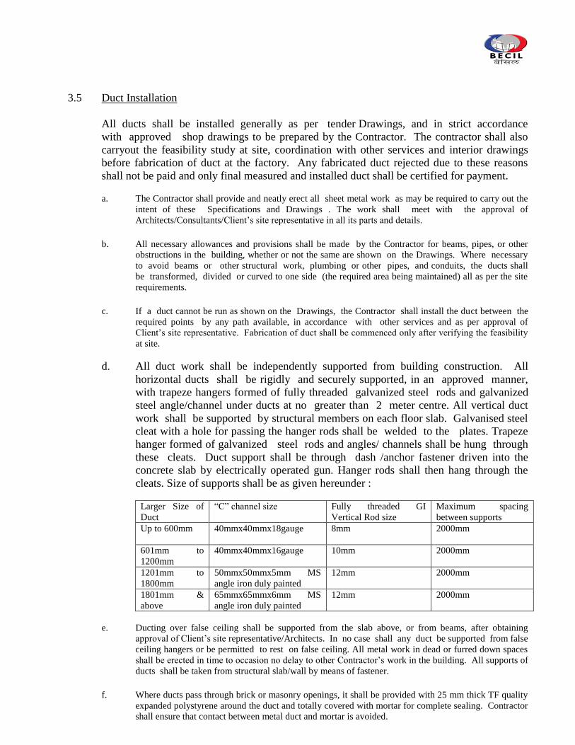
3.5 Duct Installation
All ducts shall be installed generally as per tender Drawings, and in strict accordance
with approved shop drawings to be prepared by the Contractor. The contractor shall also
carryout the feasibility study at site, coordination with other services and interior drawings
before fabrication of duct at the factory. Any fabricated duct rejected due to these reasons
shall not be paid and only final measured and installed duct shall be certified for payment.
a. The Contractor shall provide and neatly erect all sheet metal work as may be required to carry out the
intent of these Specifications and Drawings . The work shall meet with the approval of
Architects/Consultants/Client‟s site representative in all its parts and details.
b. All necessary allowances and provisions shall be made by the Contractor for beams, pipes, or other
obstructions in the building, whether or not the same are shown on the Drawings. Where necessary
to avoid beams or other structural work, plumbing or other pipes, and conduits, the ducts shall
be transformed, divided or curved to one side (the required area being maintained) all as per the site
requirements.
c. If a duct cannot be run as shown on the Drawings, the Contractor shall install the duct between the
required points by any path available, in accordance with other services and as per approval of
Client‟s site representative. Fabrication of duct shall be commenced only after verifying the feasibility
at site.
d. All duct work shall be independently supported from building construction. All
horizontal ducts shall be rigidly and securely supported, in an approved manner,
with trapeze hangers formed of fully threaded galvanized steel rods and galvanized
steel angle/channel under ducts at no greater than 2 meter centre. All vertical duct
work shall be supported by structural members on each floor slab. Galvanised steel
cleat with a hole for passing the hanger rods shall be welded to the plates. Trapeze
hanger formed of galvanized steel rods and angles/ channels shall be hung through
these cleats. Duct support shall be through dash /anchor fastener driven into the
concrete slab by electrically operated gun. Hanger rods shall then hang through the
cleats. Size of supports shall be as given hereunder :
Larger Size of
Duct
“C” channel size Fully threaded GI
Vertical Rod size
Maximum spacing
between supports
Up to 600mm 40mmx40mmx18gauge 8mm 2000mm
601mm to
1200mm
40mmx40mmx16gauge 10mm 2000mm
1201mm to
1800mm
50mmx50mmx5mm MS
angle iron duly painted
12mm 2000mm
1801mm &
above
65mmx65mmx6mm MS
angle iron duly painted
12mm 2000mm
e. Ducting over false ceiling shall be supported from the slab above, or from beams, after obtaining
approval of Client‟s site representative/Architects. In no case shall any duct be supported from false
ceiling hangers or be permitted to rest on false ceiling. All metal work in dead or furred down spaces
shall be erected in time to occasion no delay to other Contractor‟s work in the building. All supports of
ducts shall be taken from structural slab/wall by means of fastener.
f. Where ducts pass through brick or masonry openings, it shall be provided with 25 mm thick TF quality
expanded polystyrene around the duct and totally covered with mortar for complete sealing. Contractor
shall ensure that contact between metal duct and mortar is avoided.
g. All ducts shall be totally free from vibration under all conditions of operation.
Whenever duct work is connected to fans, air handling units or blower coil units that
may cause vibration in the ducts, ducts shall be provided with a fire resistant double
flexible connection, located at the unit discharge. Flexible connections shall be
constructed of fire retarding flexible heavy canvas sleeve at least 100mm long
securely bonded and bolted on both sides. Sleeve shall be made smooth and the
connecting duct work rigidly held by independent supports on both sides of the
flexible connection. The flexible connection shall be suitable for pressure at the
point of installation.
h. In case of grid type false ceiling, the entire diffuser assembly with plenum shall be
independently hung from the ceiling through adjustable GI wires and the same shall be
connected to the main duct through a flexible round duct.
i. Duct shall not rest on false ceiling and shall be in level from bottom. Taper pieces
shall taper from top.
j. Suitable arrangement shall be provided in duct for fixing of duct smoke sensor
(supplied by other vendor).
k. Toilet exhaust duct shall be provided with goose necking as shown in design drawings
and exhaust shall continue operation in case of fire.
Duct Support with Steel Wire Rope Hangers
Wire Hangers with following specifications shall be used to suspend static HVAC Air
Distribution services as required.
Wire Hangers should consist of a pre-formed wire rope sling with a range of end fixings to fit
various substrates and service fixings, these include a ferruled loop, permanently fixed
threaded M6 (or M8, M10) stud, permanently fixed nipple end with toggle, at one end or hook
or eyelet, cladding hook, barrel, wedge anchor, eyebolt anchor or any other end fixture type or
size as per manufacturers recommendation and design. The end fixings and the wire must be
of the same manufacturer with several options available. The system should be secured and
tensioned with a Hanger self-locking grip at the other end. Once the grip is locked for safety
purpose unlocking should only be done by using a separate setting key and should not be an
integral part of the self-locking grip. Only wire and/or supports supplied and/or approved,
shall be used with the system.
a. Wire Hangers should have been independently tested by Lloyds Register. APAVE, TUV, UL,
CSA, Chiltern International fire, ADCAS, Intertek, ECA, and SMACNA, approved by ULC
and CSA and comply with the requirements of DW/144 and BSRIA – wire Rope Suspension
systems. Wire rope should be manufactured to BSEN 12385: 2002
b. The contractor shall select the correct specification of wire hanger to use for supporting each
particular service from table 1 below. Each size is designated with a maximum safe working
load limit (which incorporates a 5:1 safety factor).
The correct specification of wire hanger required is determined using the following formula.
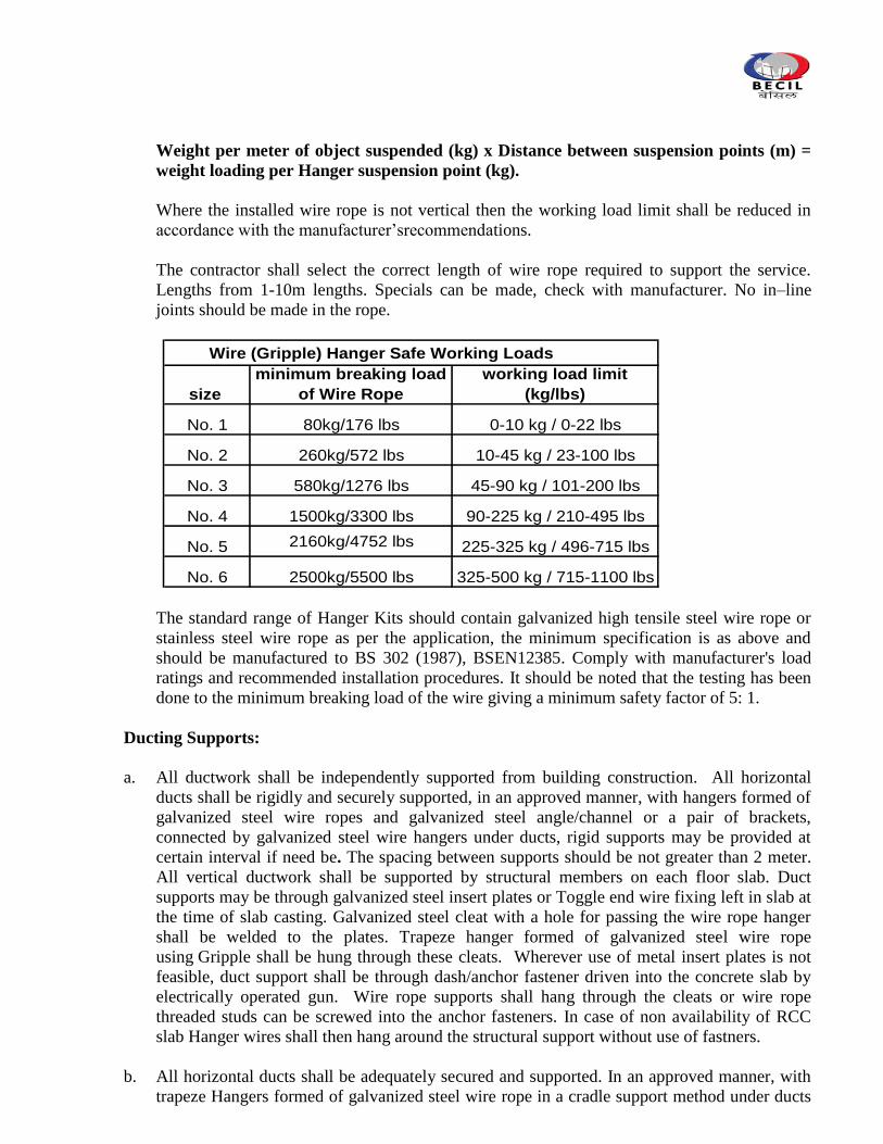
Weight per meter of object suspended (kg) x Distance between suspension points (m) =
weight loading per Hanger suspension point (kg).
Where the installed wire rope is not vertical then the working load limit shall be reduced in
accordance with the manufacturer‟srecommendations.
The contractor shall select the correct length of wire rope required to support the service.
Lengths from 1-10m lengths. Specials can be made, check with manufacturer. No in–line
joints should be made in the rope.
Wire (Gripple) Hanger Safe Working Loads
size
minimum breaking load
of Wire Rope
working load limit
(kg/lbs)
No. 1 80kg/176 lbs 0-10 kg / 0-22 lbs
No. 2 260kg/572 lbs 10-45 kg / 23-100 lbs
No. 3 580kg/1276 lbs 45-90 kg / 101-200 lbs
No. 4 1500kg/3300 lbs 90-225 kg / 210-495 lbs
No. 5 2160kg/4752 lbs 225-325 kg / 496-715 lbs
No. 6 2500kg/5500 lbs 325-500 kg / 715-1100 lbs
The standard range of Hanger Kits should contain galvanized high tensile steel wire rope or
stainless steel wire rope as per the application, the minimum specification is as above and
should be manufactured to BS 302 (1987), BSEN12385. Comply with manufacturer's load
ratings and recommended installation procedures. It should be noted that the testing has been
done to the minimum breaking load of the wire giving a minimum safety factor of 5: 1.
Ducting Supports:
a. All ductwork shall be independently supported from building construction. All horizontal
ducts shall be rigidly and securely supported, in an approved manner, with hangers formed of
galvanized steel wire ropes and galvanized steel angle/channel or a pair of brackets,
connected by galvanized steel wire hangers under ducts, rigid supports may be provided at
certain interval if need be. The spacing between supports should be not greater than 2 meter.
All vertical ductwork shall be supported by structural members on each floor slab. Duct
supports may be through galvanized steel insert plates or Toggle end wire fixing left in slab at
the time of slab casting. Galvanized steel cleat with a hole for passing the wire rope hanger
shall be welded to the plates. Trapeze hanger formed of galvanized steel wire rope
using Gripple shall be hung through these cleats. Wherever use of metal insert plates is not
feasible, duct support shall be through dash/anchor fastener driven into the concrete slab by
electrically operated gun. Wire rope supports shall hang through the cleats or wire rope
threaded studs can be screwed into the anchor fasteners. In case of non availability of RCC
slab Hanger wires shall then hang around the structural support without use of fastners.
b. All horizontal ducts shall be adequately secured and supported. In an approved manner, with
trapeze Hangers formed of galvanized steel wire rope in a cradle support method under ducts
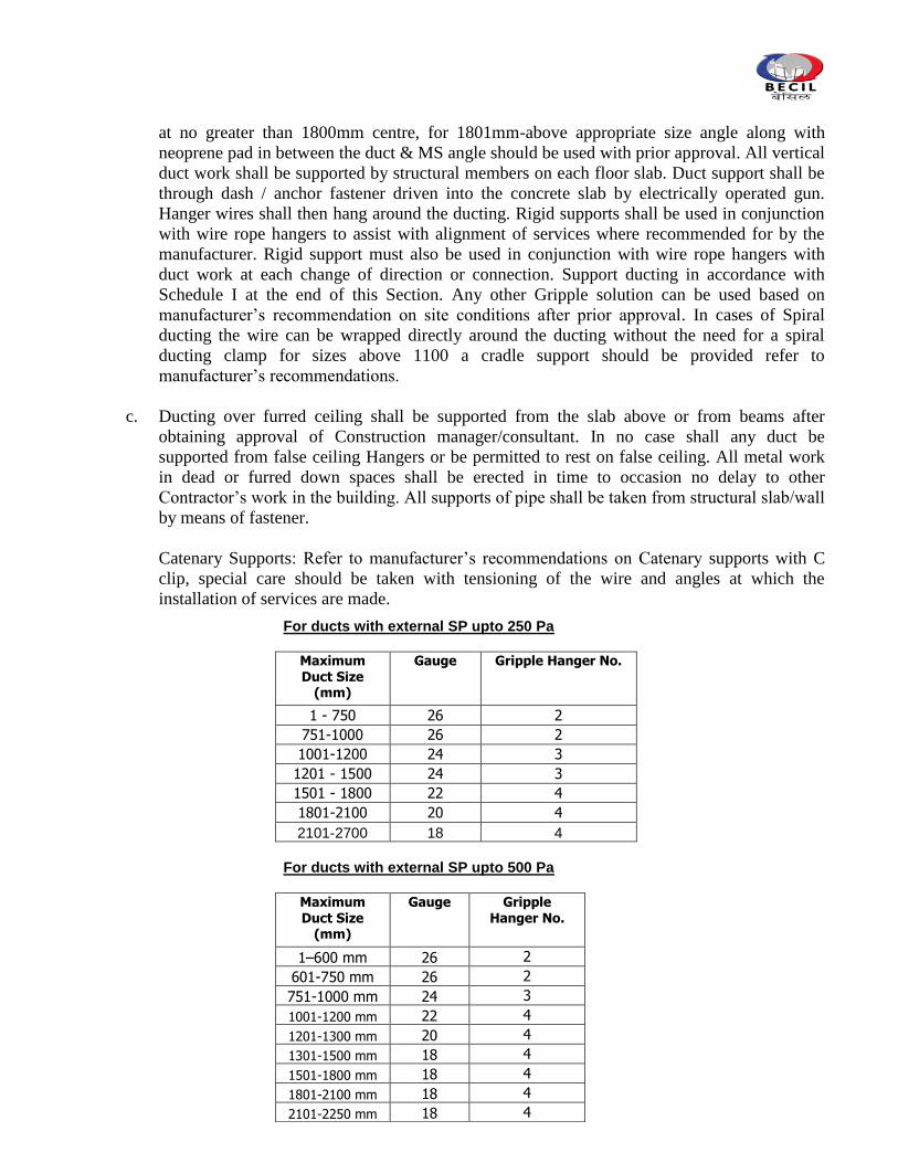
at no greater than 1800mm centre, for 1801mm-above appropriate size angle along with
neoprene pad in between the duct & MS angle should be used with prior approval. All vertical
duct work shall be supported by structural members on each floor slab. Duct support shall be
through dash / anchor fastener driven into the concrete slab by electrically operated gun.
Hanger wires shall then hang around the ducting. Rigid supports shall be used in conjunction
with wire rope hangers to assist with alignment of services where recommended for by the
manufacturer. Rigid support must also be used in conjunction with wire rope hangers with
duct work at each change of direction or connection. Support ducting in accordance with
Schedule I at the end of this Section. Any other Gripple solution can be used based on
manufacturer‟s recommendation on site conditions after prior approval. In cases of Spiral
ducting the wire can be wrapped directly around the ducting without the need for a spiral
ducting clamp for sizes above 1100 a cradle support should be provided refer to
manufacturer‟s recommendations.
c. Ducting over furred ceiling shall be supported from the slab above or from beams after
obtaining approval of Construction manager/consultant. In no case shall any duct be
supported from false ceiling Hangers or be permitted to rest on false ceiling. All metal work
in dead or furred down spaces shall be erected in time to occasion no delay to other
Contractor‟s work in the building. All supports of pipe shall be taken from structural slab/wall
by means of fastener.
Catenary Supports: Refer to manufacturer‟s recommendations on Catenary supports with C
clip, special care should be taken with tensioning of the wire and angles at which the
installation of services are made.
For ducts with external SP upto 250 Pa
Maximum Duct Size
(mm)
Gauge Gripple Hanger No.
1 - 750 26 2
751-1000 26 2
1001-1200 24 3
1201 - 1500 24 3
1501 - 1800 22 4
1801-2100 20 4
2101-2700 18 4
For ducts with external SP upto 500 Pa
Maximum
Duct Size (mm)
Gauge Gripple
Hanger No.
1–600 mm 26 2
601-750 mm 26 2 751-1000 mm 24 3 1001-1200 mm 22 4 1201-1300 mm 20 4 1301-1500 mm 18 4
1501-1800 mm 18 4 1801-2100 mm 18 4 2101-2250 mm 18 4
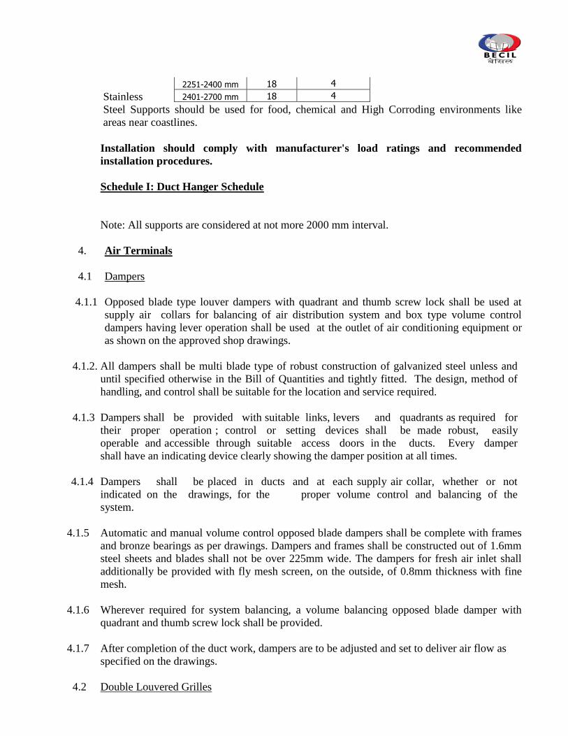
Stainless
Steel Supports should be used for food, chemical and High Corroding environments like
areas near coastlines.
Installation should comply with manufacturer's load ratings and recommended
installation procedures.
Schedule I: Duct Hanger Schedule
Note: All supports are considered at not more 2000 mm interval.
4. Air Terminals
4.1 Dampers
4.1.1 Opposed blade type louver dampers with quadrant and thumb screw lock shall be used at
supply air collars for balancing of air distribution system and box type volume control
dampers having lever operation shall be used at the outlet of air conditioning equipment or
as shown on the approved shop drawings.
4.1.2. All dampers shall be multi blade type of robust construction of galvanized steel unless and
until specified otherwise in the Bill of Quantities and tightly fitted. The design, method of
handling, and control shall be suitable for the location and service required.
4.1.3 Dampers shall be provided with suitable links, levers and quadrants as required for
their proper operation ; control or setting devices shall be made robust, easily
operable and accessible through suitable access doors in the ducts. Every damper
shall have an indicating device clearly showing the damper position at all times.
4.1.4 Dampers shall be placed in ducts and at each supply air collar, whether or not
indicated on the drawings, for the proper volume control and balancing of the
system.
4.1.5 Automatic and manual volume control opposed blade dampers shall be complete with frames
and bronze bearings as per drawings. Dampers and frames shall be constructed out of 1.6mm
steel sheets and blades shall not be over 225mm wide. The dampers for fresh air inlet shall
additionally be provided with fly mesh screen, on the outside, of 0.8mm thickness with fine
mesh.
4.1.6 Wherever required for system balancing, a volume balancing opposed blade damper with
quadrant and thumb screw lock shall be provided.
4.1.7 After completion of the duct work, dampers are to be adjusted and set to deliver air flow as
specified on the drawings.
4.2 Double Louvered Grilles
2251-2400 mm 18 4
2401-2700 mm 18 4
4.2.1 The supply air grilles shall be fabricated from extruded aluminium sections. The supply air
grilles shall have double adjustable louvers i.e. front horizontal and rear vertical louvers,
both adjustable. The louvers shall be suitable to hold deflection settings under all conditions
of velocity and pressure. The grilles shall be provided with outer frame. The louvers shall be
pivoted in Nylon bushes for smooth operation for return air grilles similar to supply air as
described above will be provided but without volume control damper. The grilles shall be
painted as per approved powder coated shade.
4.2.2 Volume control dampers in extruded aluminium construction shall be factory fitted for supply
air grilles.
4.2.3 Longer grilles having size more than 45cm shall have intermediate supports for the horizontal
louvers. The sample of grille shall have to be got approved by the consultants before delivery.
4.3 Linear Grilles
4.3.1 The linear supply cum return air grilles shall be fabricated from extruded aluminum sections.
Flanges shall be of minimum 1.3 mm thick extruded aluminum suitable to hold the louvers
tightly in fixed position.
4.3.2 Louvers shall be minimum 3mm thick throughout of extruded aluminum construction with 15
degree deflection unless and until specified otherwise. Grilles shall be provided with
removable/fixed internal core as mentioned in the BOQ. The sample of grille shall have to be
got approved by the consultants before delivery.
4.3.3 All sections of grills shall be powder coated for color and shade as approved by the
Architects to match interior finishes.
4.3.4 Linear grilles at each supply air outlet shall be provided with volume control dampers as
mentioned above and accounted for in BOQ separately. The linear grilles shall be fixed in to
a plenum chamber having GI spacers with concealed screws. End pieces or corner pieces
shall be provided as required.
4.4 Diffusers
4.4.1 Square ceiling diffuser shall be anti-smudge ring type fabricated out of extruded aluminium
sections. The four directional air flow diffuser shall consist of outer ring fixed to duct collar
with concealed screws. Foam gasket shall be provided between outer ring and suspended
ceiling. The central core shall be clip fixed to the outer ring.
4.4.2 Opposed blade volume control damper in extruded aluminium construction shall be fixed to
the neck of diffuser. The damper shall be adjusted after removing the central core.
4.4.3 All sections of diffusers shall be powder coated for color and shade as approved by the
Architects to match interior finishes. The sample of diffuser shall have to be got approved by
the consultants before delivery.
4.5 Plaque Diffuser
4.5.1 The Plaque diffusers shall be constructed out of Extruded Aluminium powder coated
sections and designed to integrate with grid type false ceiling arrangement.
4.5.2 The diffuser shall consist of a rear pan and a removable heavy gauge front flat panel attached
to the rear pan through spring loaded locking posts. The flat panel may be removed
whenever need arises to facilitate adjustment of the damper for air balancing.
4.5.3 The front panel shall be aerodynamic in appearance, rigid and preferably in single piece
construction and free from any welding or forming blemishes.
4.5.4 The horizontal air discharge pattern shall be 360 deg type . Blank off baffles shall be
provided to obtain one, two or three way blow pattern if specifically asked for in the BOQ.
Diffusers shall be provided with following accessories :
a. Opposed blade damper
b. Spiggot to facilitate round duct connection at neck.
4.5.5 The performance criteria shall be in conformity with relevant ANSI/ASHRAE standards.
4.6Multislot Linear Diffuser
Linear ceiling diffuser shall be multislot type. The diffuser shall be fabricated out of extruded
aluminium sections. Each slot shall be 19mm wide. Each slot shall be equipped with air
flow direction control louver mechanically fixed. Integral sliding type hit & miss type
volume control damper in extruded aluminium construction shall be provided for each slot
for fine control of air flow in supply air portion only. The damper shall be fabricated out of
anodized extruded aluminium sections.
Other sections of ceiling diffuser shall be powder coated in colour & shade approved by the
Consultants/Architects.
The linear diffuser shall be fixed in to a plenum chamber with concealed screws. Side end
pieces or corner pieces shall be provided if required.
4.7 Air Transfer Grille
4.7.1 Air transfer grilles shall be in extruded aluminium construction. The grilles shall be complete
with single /double frame suitable to be fixed on the door panel from both sides. The central
core shall be no-see-thru type.
4.7.2 The grilles shall be anodized or powder coated in colour and shade as approved by the
Architects. The grilles shall be provided with insect screen.
4.7.3 The ATGs shall be provided at the door of pantry and toilets as shown in the approved
drawings. The sample of grille shall have to be got approved by the consultants before
delivery.
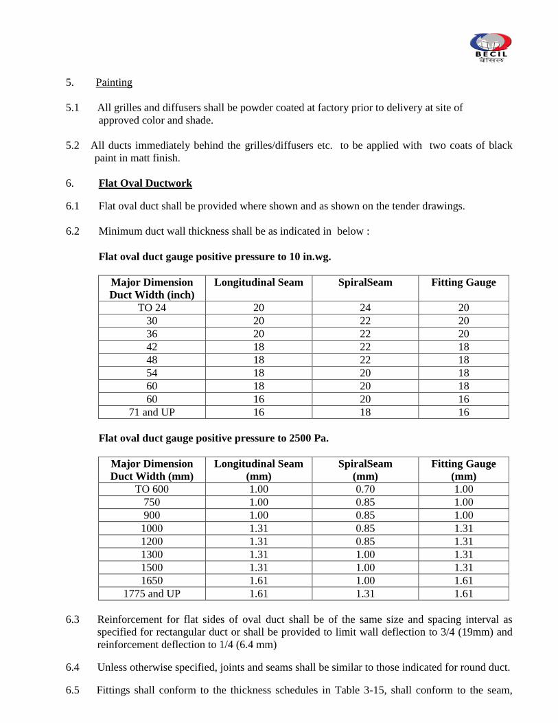
5. Painting
5.1 All grilles and diffusers shall be powder coated at factory prior to delivery at site of
approved color and shade.
5.2 All ducts immediately behind the grilles/diffusers etc. to be applied with two coats of black
paint in matt finish.
6. Flat Oval Ductwork
6.1 Flat oval duct shall be provided where shown and as shown on the tender drawings.
6.2 Minimum duct wall thickness shall be as indicated in below :
Flat oval duct gauge positive pressure to 10 in.wg.
Major Dimension
Duct Width (inch)
Longitudinal Seam SpiralSeam Fitting Gauge
TO 24 20 24 20
30 20 22 20
36 20 22 20
42 18 22 18
48 18 22 18
54 18 20 18
60 18 20 18
60 16 20 16
71 and UP 16 18 16
Flat oval duct gauge positive pressure to 2500 Pa.
Major Dimension
Duct Width (mm)
Longitudinal Seam
(mm)
SpiralSeam
(mm)
Fitting Gauge
(mm)
TO 600 1.00 0.70 1.00
750 1.00 0.85 1.00
900 1.00 0.85 1.00
1000 1.31 0.85 1.31
1200 1.31 0.85 1.31
1300 1.31 1.00 1.31
1500 1.31 1.00 1.31
1650 1.61 1.00 1.61
1775 and UP 1.61 1.31 1.61
6.3 Reinforcement for flat sides of oval duct shall be of the same size and spacing interval as
specified for rectangular duct or shall be provided to limit wall deflection to 3/4 (19mm) and
reinforcement deflection to 1/4 (6.4 mm)
6.4 Unless otherwise specified, joints and seams shall be similar to those indicated for round duct.
6.5 Fittings shall conform to the thickness schedules in Table 3-15, shall conform to the seam,
joint, and connection arrangements permitted for round duct, and shall be reinforced to
conform to 2.4.3.
6.6 The duct construction shall be capable of withstanding a pressure 50 percent greater than that
of the assigned pressure class without structural failure or permanent deformation.
6.7 Duct wall deflection at atmospheric pressure, with reinforcements and connections in place,
shall not exceed 1/4 in. (6.4 mm) on widths of 36 in. (914 mm) or less or 1/2 in (13 mm) on
greater widths. Refer Criteria in Chapter 11 of SMACNA Standards 2005 Third Edition.
6.8 Supports shall conform to those permitted for rectangular duct, with the overall dimensions
taken as references.
6.9 Documentation & Measurement of ducting
All ducts fabricated and installed should be accompanied and supported by following
documentation :
a. For each drawing, all supply of ductwork must be accompanied by computer
generated detailed bill of materials indicating all relevant duct sizes, dimensions and
quantities. ln addition, summary sheets are also to be provided showing duct area by
gauge and duct size range as applicable.
b. Measurement sheet covering each fabricated duct piece showing dimensions and
external surface area along with summary of external surface area of duct gauge-wise.
a. All duct pieces to have a part number, which should correspond to the serial number,
assigned to it in the measurement sheet. The above system will ensure speedy and
proper site measurement, verification and approvals.
7.10 Testing
After duct installation, tota! duct wcrk (Air conditioning and MechanicalVentilation Ducts for
Kitchen and toilet exhaust )carried out under this scope of works should be tested for leakage.
The procedure for leak testing should be followed as per SMACNA -" HVAC Air Duct
Leakage test manual” (First Edition-1985)
8. Flexible Ducts
The scope of this section comprise supply, installation testing and commissioning of flexible
ducting conforming to these specifications and in accordance with requirements of drawings
and schedule of quantities.
Wherever specified, uninsulated flexible duct shall be made of double lamination of metalized
polyester film permanently bonded to a coated spring steel wire helix. Duct shall be in tear
and puncture resistant construction.
Wherever insulated flexible ducts are specified, inner core for the same should be made of
double lamination of polyester film permanently bonded to a coated spring steel wire helix.
Fiberglass insulation of minimum 24Kg/m3
density, 25mm thickness shall be wrapped over
the inner core and covered with strong outer jacket cum vapour barrier made of fiberglass
reinforced metalized polyester film laminate.
Care must be taken to install the entire flexible duct in fully extended position and bends
made with adequate radius as per manufacturer recommended practices.
9. Testing and Balancing
9.1 After completion of the installation of the complete air distribution system, all ducts shall be
tested for air leaks using method as approved by the Consultants.
9.2 Before painting the interiors, air distribution system shall be allowed to run continuously for
48 hours for driving away any dust or foreign material lodged within ducts during installation.
9.3 The entire air distribution system shall be balanced using approved anemometer. Air
quantities at the fan discharge and at various outlets shall be identical to, or less than 5
percent in excess of, those specified and quoted. Leakage in each air distribution system
shall be within 3 percent so that supply air volume at each fan shall be identical to , or no
greater than 3 percent in excess of, the total air quantity measured at all supply outlets served
by the fan. Branch duct adjustments shall be made by volume or splitter dampers. Dampers
shall be permanently marked after air balance is complete so that these can be restored to
their correct position if disturbed at any time. Complete air balance report shall be
submitted to the Consulting Engineer for scrutiny and approval, and six copies of the
approved report shall be provided with completion documents.
***************************
F. “SPECIFICATIONS - INSULATION”
1. Scope
The scope of this section comprises of supply and application of insulation conforming
to these Specifications and as shown on the drawings & BOQ.
2. Duct Insulation (External)
Material
Insulation material shall be closed cell elastomeric material (nitrile rubber) having fire
retardant Class “O” properties. Density of insulation material shall range between 0.04-0.07
gm/Cucm. Thermal conductivity (K value) at 40 C mean temperature and Service
temperature limit shall be 0.039 W/M.K and –40C to 105C respectively. Water vapour
permeability shall not be less than 7000 Kg/Pa/s.m.Water absorption shall not be more than
1.5% by weight. Insulation material shall have excellent ozone resistance properties.
Excellent Thermal Stability. Insulation material shall be tested for the said properties in
accordance with the relevant international codes including BS 874 Part 2 1986, DIN
52612(K Value),DIN 52615 (Water vapour permeability), BS 476 Part6 & Part7
(Flammability).
Application
Duct insulation shall be applied as follows :
a. External surface of the ducts to be cleaned vigorously to remove dirt and any other
foreign material from the surface of the ducts.
b. Apply Low VOC adhesive on the surface of ducts.
c. Wrap factory aluminum foil laminated finish closed cell insulation material having
thickness as mentioned in BOQ butting all joints. All joint to be sealed with adhesive.
3. Acoustic Lining of Ducts
3.1 Material
Acoustic insulation material shall generally possess the properties mentioned above,
however, insulation material shall be processed Nitrile Rubber Foam having fire retardant
Class “O” properties. Density of insulation material shall range between 140-180 Kg/CuM.
The insulation material shall conform to the international codes including BS 476 Part6 &
Part7 (Flammability).
3.2 Application
Acoustical lining of duct wherever specified shall be applied as under :
a. Internal surface of the ducts to be cleaned vigorously to remove dirt and any other
foreign material from the surface of the ducts
b. Apply Low VOC adhesive on the surface of ducts.
c. Cut foamed sheets into required sizes using sharp knives. Apply adhesive on the
foam and stick it to the duct surface.
OR
3. Accoustic Lining
3.1 Material
Insulation material shall be resin bonded fibreglass. The Thermal conductivity of the
insulation material shall not exceed 0.034 K cal./ hr-SqM C/M or 0.27 Btu/hr sft- F/inch at
32 C (90 F) mean temperature, and density shall not be less than 24 Kg/ CuM (1.5 lb/c.ft).
Thickness of the insulation shall be as specified for the individual application. Samples of
insulation material shall be submitted for approval.
3.2 Application
3.2.1 Duct Lining (Internal)
Acoustical lining of duct wherever specified shall be applied as under :
a. Internal surface of the ducts to be cleaned vigorously to remove dirt and any other
foreign material from the surface of the ducts
b. 22 gauge G.S. Sheet channel frames having size 25mm wide & depth equal to
thickness of insulation to be fixed at maximum 600mm centre, screwed to the
sheet metal using brass metal screws.
c. Fibre Glass blankets of 32 Kg/CuM density and thickness as mentioned in the
BOQ to be fixed in the G.S.sheet channel frame work with joints well butted
together. Thereafter, insulation shall be covered with R.P tissue.
d. Finally cover the insulation with 26 SWG perforated aluminium sheet having
atleast 20% perforation with joints overlapped and screwed to the G.S. Sheet
channel frame using brass metal screws, to produce an even surface.
Note : specifications shall be applicable as specified in the BOQ.
4. Exposed Ducts Thermal Insulation
4.1 General
The insulation of ducts exposed to atmosphere shall be carried conforming to these
Specifications and as shown on the drawings.
42 Material
Insulation material shall be expanded polystyrene having density not less than 24Kg/CuM.
4.3 Application
Method for application of Insulation externally shall be as given hereunder :
a. External surface of the ducts to be cleaned vigorously to remove dirt and any other
foreign material from the surface of the ducts.
b. Apply adhesive SR-998/505 on the surface of ducts
c. Wrap closed cell insulation material having thickness as mentioned in BOQ butting
all joints. All joints to be sealed with adhesive.
d. Finally apply necessary glass cloth coating & UV protection paint of approved make
to protect the insulation material from atmospheric abuse.
5. Underdeck Thermal Insulation for Exposed Roof
Material
Insulation material shall be closed cell elastomeric material (nitrile rubber) having fire
retardant Class “O” properties. Density of insulation material shall range between 0.04-0.07
gm/Cucm. Thermal conductivity (K value) at 40 C mean temperature and Service
temperature limit shall be 0.039 W/M.K and –40C to 105C respectively. Water vapour
permeability shall not be less than 7000 Kg/Pa/s.m.Water absorption shall not be more than
1.5% by weight. Insulation material shall have excellent ozone resistance properties.
Excellent Thermal Stability. Insulation material shall be tested for the said properties in
accordance with the relevant international codes including BS 874 Part 2 1986, DIN
52612(K Value), DIN 52615 (Water vapour permeability), BS 476 Part6 & Part7
(Flammability).
Application
Following procedure towards application of closed cell elastomeric insulation material having
properties as mentioned above for roof exposed to sun shall be adopted :
a. The underside of the roof slab surface to be thoroughly cleaned with wire brush and
rendered free from bitumen or any time or any other coating that exists.
b. Basic surface preparation using sand paper.
c. Adhesive LOW VOC to be applied thereafter, preferably in the evening and be left
for overnight.
d. Finally next morning 16mm thick CSE insulation to be applied using adhesive with
longitudinal and cross sectional joints glued properly and left open to facilitate
inspection. Thereafter, CSE adhesive based tapes shall be applied on such
longitudinal and transverse joints.
e. Metal screws shall be fixed with dash fasteners at centre of each piece of CSE
insulation with a GI cleat at bottom to give extra precaution in fixing of insulation.
***************************
F. “SPECIFICATIONS - ELECTRICAL WORK”
1. Scope
In general, the contractor shall supply, store, erect, test and commission all the equipment
required for Electrical Installation. The contractor shall furnish all the materials, labour, tools
and equipments for the electrical work, as shown in the accompanying drawings and in the
bill of quantities and specifications hereinafter described.
2. Definitions
The following abbreviations used in the bill of quantities specifications and drawings
represents:
ISS - Indian Standard specification.
IER - Indian Electricity Rules, 1956.
BS - British Standard (where specifically called for)
BSCP - British Standard Code of Practice (if called for).
HRC - High Rupturing Capacity
GI - Galvanised Iron
MS - Mild Steel
CI - Cast Iron
APLSTS - Aluminium conductor, paper insulated lead sheathed, Double steel tape
armoured and serving.
PVC - Polyvinyl Chloride.
XLPE - Cross Linked Polyethylene.
HT - High Tension.
LT - Low Tension.
A-Amp - Ampere.
KV - Kilo Volts.
PT - Potential Transformers.
CT - Current Transformers.
OCB - Oil circuit Breakers
VCB - Vacuum Circuit Breaker
ACB - Air Circuit Breakers
SFU - Switch fuse Unit
COS - Change Over Switch
CFS - Combination Fuse Switch
MCCB - Moulded Case Circuit Breaker.
MCB - Miniature Circuit Breaker
IC - Iron Clad
ICTPN - Iron Clad Triple Pole and Neutral
ICDP - Iron Clad Double Pole
DB - Distribution Board
KVA - Kilo Volts Ampere.
KVAR - Kilo Volts Ampere - Reactive.
NC - Normally Close
NO - Normally open
SWG - Standard Wire Gauge.
3. REGULATION & STANDARDS
The installation shall conform in all respects to Indian standard Code of Practice for Electrical
Wiring Installation I.S. - 732 and „National Electrical Code‟. It shall be in conformity with the
current I.E Rules and Regulations and requirements of the local Electric Supply Authority in-
so-far as these become applicable to the installation. Wherever this specification calls for a
higher standard of materials and/or workmanship then those required by any of the above
regulations, this specifications shall take precedence over the said regulations and standards.
In general, the materials, equipments and workmanship not covered by the above, shall
conform to the following Indian Standards (Latest Edition) unless otherwise called for:
a. SWITCHGEAR
Requirements of A.C. Circuit Breakers. : IS 2516 (Part I) Sec.1,2 & 3 (Part-II)
Switches and Switch Isolators above 1000V
But Not Exceeding 1.1 KV : IS 4710
Markings & arrangements for switchgear
bus-bars, main connection & auxiliary wiring : IS 375
Specification for normal duty air break switches
& composites unit for air break switches and fuses
for voltage not exceeding 1000 Volts. : IS 4064
Heavy duty air-break switches and composite
units of air-break switches and fuses for
voltages not exceeding 1000 Volts. : IS 4047
Specification for miniature circuit breakers. : IS 8828
Specification for enclosed distribution, fuse
boards and cut-outs for voltage not exceeding
1000 Volts : IS 2675
Installation and maintenance of switchgear. : IS 3072 (Part I)
HRC cartridge fuse links 650 Volts. : IS 2208
b. CABLE & MISCELLANEOUS ITEMS
Specification for paper insulated and lead
sheathed cables : IS 692
Code of Practice for installation and maintenance
of paper insulated power cables (upto and
including 33 KV) : IS 1255
Specification for PVC insulated (Heavy Duty)
electric cables Part-I for Voltage upto 1100 Volts. : IS 1554
Specification for PVC insulated cables (for
voltage upto 1100 V) (Part-II) with Aluminium
conductors. : IS 694 (Part-II)
Specification for rigid steel conduit for electrical
wiring. : IS 9537
Specifications for rigid non metallic conduits for
electrical installations. : IS 9537
Specifications for accessories for rigid steel
conduits for Electrical wiring. : IS 3837
Box for the enclosure of electrical accessories
steel and C.I. Boxes. : IS 5133 (Part I)
3Pin plugs and sockets outlets : IS 1293
Adhesive insulating tapes for Electrical
purposes (Part- I & II) : IS 2448
Propeller type AG Ventilating fans : IS 2312
Code of Practices for earthing. : IS 3043
Glossary of terms for electrical cable and
conductors. : IS 1885
Code of Practice for buildings (General)
Electrical installation : IS 1646
Current Transformers : IS 2705 (Part-I to III)
Voltage Transformer : IS 3156 (Part-I to III)
Shunt capacitors for Power system : IS 2834
Direct acting electrical indicating instruments : IS 1246
Factory assembled switchgear : IS 8623
Rating for Cable : IS 3961 (Part -II)
Earthing : IS 3843
3. INSPECTION & APPROVAL OF THE WORK BY LOCAL AUTHORITY
On completion of this work, the contractor shall obtain and deliver to the owners the
certificates of inspection and approval by electrical inspectorate of Local Administration.
The fees paid for inspection will be reimbursed on production of challan/receipt. The
contractor shall include in his rates all charges necessary for getting electrical installation
approved which includes Sub-station, LT distribution, etc. by the Chief Electrical Inspector
to the state government or/ and from any other authority required for this job.
5. INSPECTION OF MATERIALS
The Architect/ owners shall have access to the manufacturer‟s premises for inspection of any
items of the tender for which contractor has made arrangement with manufacturer/ suppliers.
All such inspection shall not need any prior intimation by the owners or architects.
6. WORKING DRAWINGS & SHOP DRAWINGS
The contractor shall prepare and submit to the Architects/ owners for approval detailed
working drawings & shop drawings of all MCC/panels ,cable layout, earthing etc.
7. AS BUILT DRAWINGS
At the completion of the work and before issuance of certificate of virtual completion, the
contractor shall submit to the Architect/ employers layout drawings drawn on tracing film
and approved scale indicating the complete wiring as installed.
8. ENGINEER/ SUPERVISOR
The contractor shall employ a competent, licence, qualified full time electrical engineer /
supervisor to direct the work of electrical installations in accordance with the drawings and
specifications. The engineer / supervisor shall be available at all times at the site to receive
instructions from the Architect/employers in any day to day activities throughout the
duration of the contract. The engineer & supervisor shall correlate the progress of the work
in conjunction with all the relevant requirements of the supply authority. The skilled workers
employed for the work should have requisite qualifications and should possess competency
certificate from the Electrical Inspectorate of Local Administration.
9. APPLICATION FOR ELECTRIC SUPPLY/ LIASON
The Contractor shall be responsible for filing and follow up application for electric supply to
the project. The contractor shall carry out all the liason work required for obtaining electric
supply at site commencing from filing of application. This liason shall be deemed to be a part
of the contract.
GENERAL SPECIFICATION FOR: MEDIUM VOLTAGE POWER CONTROL
CENTRE AND SWITCH BOARD PANELS:
1.1 GENERAL:
Medium voltage power control centres (generally termed as switch board panels) shall be in
sheet steel clad cubicle pattern, free floor standing type, totally enclosed, compartmentalized
design. This specification shall cover the following types of panels :
a) Air circuit breaker panels - Drawout type with single or double tier arrangement as per
design shown on the drawings.
b) Panels with one or more Air circuit breakers with Draw-out arrangement and switch-fuse
units/moulded case circuit breaker of non-drawout design.
c) Panels with switch- fuse unit/moulded case circuit breaker of non- drawout type. However,
the switch-fuse units can have drawout fuse-carriage if a particular make of switch-fuse is
used.
The panels shall generally be of extensible type with provision for bus extension on or both
sides as desired at the time of approved of shop drawings.
1.2 CODE/STANDARDS :
The panels shall generally conform to the requirements of following codes/ specifications:
a) IS-8623 h) IS-2705
b) IS-4237 i) IS-722
c) IS-2147 j) IS-4064
d) IS-3072 k) IS-2208
e) IS-375 l) IS-6875
f) IS-1248 & 2419 m) IS-6005
g) IS-5082
The equipment shall conform to Indian Electricity Rules as amended upto-date.
The supplier shall examine the provision of these codes and confirm or indicate his
comments.
1.3 CONSTRUCTION :
Power control centres/ switch board panels shall of free standing type, with sheet steel
enclosure having following features :
a) The panel shall be constructed of sheet steel of minimum 1.6mm thickness. The internal
frames shall be made of structural steel angles or made up sections (as per standard
design of the manufacturer) specifications of which, shall be submitted along with offers.
b) The panel shall be compartmentalised to accommodate one feeder n each compartment.
The main bus bar chamber shall be provided at the top of panel or bottom of the panel as
required. The compartments shall be arranged in section with metallic/ phenolic barrier in
between.
A vertical cable alley of at least 200mm width shall be provided to serve one/ two
vertical section of feeders. Cable alley shall have hinged door/ doors with rubber gaskets.
Suitable
cable clamping arrangement with slotted steel members shall be provided in the cable
alley. Similarly, vertical bus bar shall be housed in-between two feeder compartments in
a separate bus chambers. The opening between bus chamber and feeder compartments
shall be properly covered with Bakelite/ Hylam sheets of 3mm minimum thickness. The
vertical bus chamber shall be provided with removable bolted covers on the front and
back side. All the interconnecting links to the feeders shall be shrouded so as to avoid
accidental contact, by means of phenolic barriers.
c) Each compartment shall have its own hinged door with concealed hinges. The doors shall
have heavy duty rubber gasket fixed on the inner side of the door. The door shall have
interlocking facility with the feeder unit.
d) The Panel shall have punched openings for mounting meters, lamps, push buttons, relays,
etc.
e) The dimensions of feeder compartments, bus chambers and cable alleys shall be as
shown on the relevant drawings. However, the following minimum dimensions shall be
strictly adhered to :
i. ACB compartment : Drawout -600mm wide x 1000mm deep x
900mm high.
ii. SWITCH FUSE UNITS/MOULDED CASE CIRCUIT BRACKER (NON-
DRAWOUT TYPE) :
Up to 63A/ 100A : 300mm wide x 225mm high x 400mm deep
250A : 400mm wide x 400mm high x 400mm deep
400A to 630A : 400mm wide x 500mm high x 400mm wide.
(or vice- versa).
iii. BUS CHAMBER :
Main bus (Horizontal) : 400mm high x 300mm deep
Vertical bus (Feeder bus) : 300mm wide x 400mm deep
iv. Cable alley : Min. 200mm wide.
These dimensions are furnished as a guide and the clearances required in between each live
bus/ link and between bus/ links to the earth (panel wall/ sheet) shall be as per relevant
Indian Standard Code of practice. However, minimum clearance between neutral bus and
earth shall not be less than 25mm. The panel supplier shall furnish detailed sectional
drawings and also arrange to get the panel inspection done at intermediate stages of
fabrication to avoid fault defective febrication of the panels (however, the compliance of
these specifications shall entirely be the suppliers‟ responsibility).
1.4 BUS BARS :
a) The bus bars shall be suitable for 3 phase, 4 wire, 415 volts 50 Hz AC supply. The bus bars
shall be made of high conductivity aluminium. The bus bars shall have uniform cross-section
throughout the length. The bus bars shall be designed for carrying rated-current continuosly.
The bus bars and links shall be designed for a maximum temperature of 75OC. The max.
current density of bus bars shall be as follows:
i. Copper : 1.86 Ampere/ Sq.mm. of cross section area.
ii. Aluminium : 1.28 Ampere/ Sq.mm. of cross section area.
It may be noted that these ratings are the upper limit to which the bus could be stressed.
Suitable derating factors shall be applied to arrive at the correct cross section of bus bars.
b. Bus bars shall be supported on suitable non hygroscopic, non combustible, material such
as DMC/ SMC at sufficiently close intervals to prevent bus bar sag. All bus bar joints
shall be provided with high tensile steel bolts (electro plated with suitable metal such as
Nickel/ Cadmium), spring washer and nuts so as to ensure good contact. Alternatively,
electroplated/ tinned brass bolts shall be used. The joints shall be formed with fish-plates
on either side of bus bar to provide adequate contact area. Bus supports shall be provided
on either side of joints (max. unsupported distance from the joint 400mm)
c. Power shall be distributed to feeders in dual section by a set of vertical bus bars
(Phases+neutral). Individual module shall be connected to the vertical bus bars through
sleeved connections.
d. Bus bars shall be insulated with PVC sleeves (heat shrink type) with colour coding (Red/
Blue/ Yellow/ Black).
e. The bus bars and their supports shall be able to withstand thermal and dynamic stresses
due to the system short-circuits. The supplier shall furnish calculations alongwith his
drawing establishing the adequacy of bus bars both for continuous duty and short -circuit
rating. Short circuit withstand capacity shall be for one second. Calculations for spacing
of supporting of supports shall also be furnished.
1.5 EARTHING :
The panels shall be provided with a copper earth bus running throughout the width of the
switchboard. Suitable earthing eyes/bolts shall be provided on the main earthing bus to
connect the same to the earth grid at the site. Sufficient number of star washers shall be
provided at the joints to achieve earth continuity between the panels and the sheet metal parts.
1.6 MOUNTINGS :
Panels incorporating switchfuse units shall have suitable compartments of standard width.
Each compartment shall incorporate a heavy duty load break switch fuse and HRC fuses.
Suitable cable termination arrangement shall be provided for switch fuse/ fuse-switch unit
feeders. Equipment shall be provided with proper fastening arrangements to ensure vibration
free operation. Proper designation as given on the respective drawings, shall be provided for
every equipment.
Circuit breakers shall be mounted such that they are accessible from the front of the panel.
More than two circuit breakers shall not be incorporated in a vertical section. The breakers
compartment shall be divided into two parts, one for the breaker and the other for
incorporating associated control gear. The necessary instrumentation shall be provided on the
door of the compartment.
1.7 INTERLOCKING
The panels shall be provided with the following interlocking arrangements :
a. The door of the feeder compartments is so interlocked with the switch drive or handle
that the door can be opened only if the switch is in “OFF” position. De-interlocking
arrangement shall also be provided for inspection.
b. It shall not be possible for the breakers to be withdrawn when in “ON” position.
c. It shall not be possible for the breakers to be switched “ON” unless it is either in fully
inserted position or for testing purposes it in fully isolated position.
d. The breaker shall be capable of being racked into “testing”, “isolated” and
maintenance position and kept in any of these positions.
e. A safety catch to ensure that the movement of the breaker as it is withdrawn, is
checked before it is completely out of the cubicle shall be provided.
1.8 PROTECTION AND INSTRUMENTATION :
Protection and instrumentation shall be as per standard specification.
1.9 WIRING
All the interconnections between the incoming, bus and the outgoings of 100A and above
rating shall be done by insulated links/ strips of suitable sizes. Switch fuses and equipments
below 100A rating shall be wired with PVC insulated copper conductors. The wiring for
instrumentation protection and control equipment shall be carried out with PVC insulated
flexible copper conductors.
The Power interconnections shall be carried out by means of bolted connections with
washers. The wiring shall be terminated by using crimping sockets. Wring shall be laid out
neatly in bunches which are fastened to the steel members of the panel. All the potential
circuits shall be protected by fuses mounted near the tap-off point from the main
connections.
1.10 TERMINALS:
All the control, instrumentation and protection wiring shall be provided with printed PVC
ferrules at both ends. For terminating control cables on to the equipment in the panels,
suitable terminals blocks shall be provided. The terminal shall also be numbered for easy
identification and maintenance.
1.11 SURFACE TREATMENT
All sheet metal accessories and components of power, control centres and switchboard
panels shall be thoroughly cleaned, degreased, derusted and phosphatised before redoxide
primer is applied. The panel shall be stove enameled to the required final finish. The interior
surfaces of the panel shall also be painted to required shade. The supplier shall indicate in his
offer, if there is any deviation from the treatment specified above.
1.12 ENCLOSURES
The panel enclosure shall be dust and vermin proof and shall be suitable for indoor
installation. Enclosure design shall be in accordance with the requirements of IP 54 as per
IS-2147-1962. The supplier shall confirm whether this requirement is met and a type test
certificate furnished. If type test certificate for IP-54 is not available, the same shall be
brought out clearly in his offer.
1.13 NAME PLATE
The panel as well as the feeders compartment doors shall be provided with name plates
giving the switchboard/ feeder descriptions as indicated on the drawings.
1.14 TESTING
The power control centres shall be tested at factory after assembling of all components and
completion of all interconnections and wiring. Tests shall be coducted in accordance with the
requirements relevant IS Codes/ specifications.
a. INSULATION TEST
i. Insulation of the main circuit, that is, the insulation resistance of each pole to the
earth and that between the poles shall be measured.
ii. Insulation resistance to earth of all secondary wiring should be tested with 1000V
megger.
Insulation test shall be carried out both before and after high voltage test.
b. HIGH VOLTAGE TEST :
A high voltage test with 2.5KV one minute shall be applied between the poles and earth. Test
shall be carried out on each pole in turn with the remaining poles earthed. All units racked in
position and the breakers closed. Original test certificate shall be submitted along with panel.
1.15 STORING, ERECTION AND COMMISSIONING
a. STORING
The panels shall be stored in a well ventilated, dry places. Suitable polythene covers shall
be provided for necessary protection against moisture.
b. ERECTION
Switchboards shall be installed on suitable foundation. Foundation shall be as per the
dimensions supplied by the panel manufacturer. The foundation shall be flat and level.
Suitable grouting holes shall be provided in the foundation. The switch boards shall be
properly aligned and bolt000ed to the foundation by atleast four bolts. Cable shall
terminated on the bottom plate or top plate as the case may be, by using brass
compression glands. The individual cables shall then be lead through the panel to the
required feeder compartments for necessary terminations. The cables shall be clamped to
the supporting arrangement. The switch board earth bus shall be connected to the local
earth grid.
c. PRECOMMISSIONING TESTS :
Panels shall be commissioned only after the successful completion of the following tests.
The tests shall be carried in the presence of engineer-in-charge.
i. All main and auxiliary bus bar connections shall be checked and tightened
ii. All wiring terminations and bus bar joints shall be checked and tightened.
iii. Wiring shall be checked to ensure that it is according to the drawing.
iv. All wiring shall be tested for insulation resistance by a 1000V megger.
v. Phase sequence/ rotation shall be estimated.
vi. Suitable injection tests shall be applied to all the measuring insuring instruments to
establish the correctness and accuracy of calibration and working order.
iii. All relays and protective devices shall be tested for correctness of settings and
operation by introducing a current generator and an ammeter in the circuit.
GENERAL SPCIFICATION FOR : MOULDED CASE CIRCUIT BREAKERS
1.1 GENERAL :
Moulded case circuit breakers or fuse free breaker shall be incorporated in the switch board
wherever specified. MCCBS shall conform to BS : 3871 Part II or JIS-C-8370 in all respects.
MCCBS shall be suitable either for single phase 230V or three phase 415volts.
1.2 CONSTRUCTION :
The MCCB and case shall be made of high strength heat resistant and flame retardant thermo-
setting insulating material. Operating handle shall be quick make/quick break, trip-free type.
The operating handle shall have suitable “ON”, “OFF” and “TRIPPED” indicators. Three
phase MCCBS shall have a common operating handle for simultaneous operation and
tripping of all the three phase. Suitable arc extinguishing device shall be provided for each
contact. Tripping unit shall be of thermal-magnetic type provided on each pole and
connected by a common trip bar such that tripping of any one pole actuates three poles to
open simultaneously. Thermal magnetic/tripping device shall have IDMT characteristics for
sustained over loads and short circuits. Contact tips shall be made of suitable are resistant,
sintered alloy for long electrical life. Terminals shall be of liberal design with adequate
clearances.
1.3 ACCESSORIES :
MCCBS shall be provided with the following accessories, if specified in schedule of
quantities:
i. Under voltage release
ii. Shunt release
iii. Alarm Trip alarm
iv. Auxiliary contacts.
1.4 INTERLOCKING :
Moulded case circuit breakers shall be provided with the following interlocking devices for
interlocking the door of switch board:
a. Handle interlock to prevent unnecessary manipulation of the breaker.
b. Door interlock to prevent the door being opened when the breaker is in “ON” position.
c. De-interlocking device to open the door even, if the breaker is in “ON” position.
1.5 RUPTURING CAPACITY:
The moulded case circuit breaker shall have a returning capacity of not less that 10KA Rms
at 415 volts. Wherever required, higher rupturing capacity breakers to meet the system short
circuit fault shall be used. All such ratings shall be as per equipment schedule/B.O.Q.
1.6 TESTING:
a. Original certificate of the MCCBS as per BS:3871 or JS-C-8370 shall be furnished.
b. Pre-commissioning tests on the switch boards panel incorporating the MCCB shall be
done as per specifications.
GENERAL SPCIFICATION FOR: MEDIUM VOLTAGE CABLES
1.1 TYPE :
Medium voltage cables shall be aluminium conductor, PVC insulated, PVC sheathed and
steel wire armoured or steel tape armoured construction. Aluminium conductors up to
10sq.mm. may be solid, circular in cross section, and sizes above 10sq.mm. shall be
stranded. Sector shaped stranded conductors shall be used for sizes above 25sq.mm. The
cable shall conform to IS 1554 (Part I).
1.2 RATING
The cable shall be rated for a voltage of 650/1100 Volts.
1.3 CONSTRUCTION
The conductors for power cables shall be made of electrical purity aluminium & that for
control cable from annealed high conductivity copper. The conductors shall be insulated with
high quality PVC base compound. A command covering (bedding) shall be applied over the
laid up cores by extrusion or wrapping of a filling material containing unvulcanized rubber
or thermoplastic material, armouring shall be applied over the inner shath of bedding, over
the armouring a tough outer sheath of PVC sheathing shall be extruded. The outer sheath
shall bear the manufacturers name and trade mark at every 30 meter interval.
1.4 CORE IDENTIFICATION :
Core shall be provided with the following colour scheme of PVC insulation.
i. Core : Red/Black/Yellow/Blue
ii. Core : Red and Black
iii. Core : Red, Yellow, and Blue
iv. 3.5/4 core : Red, Yellow, Blue and black.
1.5 CURRENT RATINGS :
The current rating shall be based on the following conditions.
i. Maximum conductor temperature : 70OC
ii. Ambient air temperature : 40OC/50
OC
iii. Ground temperature : 70OC
iv. Depth of laying : 75cm
1.6 SHORT CIRCUIT RATING:
Short circuit ratings for the cables shall be as specified in IS : 1554 Part -I.
1.7 SELECTION OF CABLES :
Cables have been selected considering the conditions of the maximum connected load,
ambient temperature, grouping of cables & the allowable voltage drop. However, the
contractor shall recheck the sizes before the cables are fixed and connected to the service.
a. Storing
All the cables shall be supplied in drums. On receipt of cables at site, the cables shall be
inspected and stored in drums with flanges of the cable drums in vertical position.
b. Laying
Cables shall be laid as per the specifications given below. The system adopted for this
job shall be as per BOQ :
i. Cable on Tray/ Racks:
Cables shall be laid on cable trays/ racks wherever specified. Cable racks/trays
shall be of ladder, trough or channel design suitable for the purposes. The
nominal depth of the trays/ racks shall be 150mm. The width of the trays shall be
as per the design shown on drawing. The cable trays shall be made of steel or
aluminium. The trays/ racks shall be completed with end plates, tees, elbows,
risers, and all necessary hardware. Steel trays/ Rack shall be painted with two
coats of enamel paint of approved shade over a coat of red oxide primer. Cable
trays shall be erected properly to present a neat and clean appearance. Suitable
cleats or saddles made of aluminium strips with PVC covering shall be used for
securing the cables to the cable trays. The cable trays shall comply with following
requirements :
1. The trays shall have suitable strength and rigidity to provide adequate supports
for all contained cables.
2. It shall not present sharp edged, burrs or projections injurious to the insulation of
the wiring/ cables.
3. If made of metal, it shall be adequately protected against corrosion or shall be
made of corrosion resistant material.
4. It shall have side rails or equivalent structural members.
5. It shall include fittings or other suitable means for changes in direction and
elevation of runs.
1.9 INSTALLATION
1. Cable trays shall be installed as a complete system. Trays shall be supported properly
from the building structure. The entire cable tray system shall be rigid.
2. Each run of the cable tray shall be completed before the installation of cables.
3. In portion where additional protection is required, non combustible covers/ enclosures
shall be used.
4. Cable tray shall be exposed and accessible.
GENERAL SPECIFICAITON FOR: EARTHING FOR ELECTRICAL WORK
1.1 General
All non-current carrying metal parts of the electrical installation shall be earthed as per IS:
3043. All metal conduits, trunkings, cable armour, switchgear, distribution boards, meter,
light fixtures, fans and all other metal parts forming part of the work shall be bonded
together and connected by two separate and distinct conductors to earth electrodes. Earthing
shall also be in conformity with the provisions of Rules 32, 61, 62, 67 & 68 of IER 1956.
These specifications apply to both copper and GI earthing system. The material to be used
shall be as per that give in BOQ.
1.2 Earthing Conductors
1.2.1 All earthing conductors shall be of high conductivity copper or GI and shall be protected
against mechanical damage and corrosion. The size of earth conductors shall not be less
than half that of the largest current carrying conductor. The connection of earth continuity
conductors to earth bus and earth electrodes shall be strong and sound and shall be easily
accessible. The earth tapes shall be joined together using double rivets. The earthing
conductor shall be laid in cable trenches, cable trays or conduits or on cable by using
suitable clamps made of non-ferrous metals compatible with the earthing conductor. The
following earthing conductors and required to be used for various sections of the
installations.
a. 10SWG bare copper wire or GI wire.
b. All single phase switches and DBs above 30A and upto 63A rating shall be earthed with
one run of 8SWG bare copper wire or GI wire.
c. All three phase switches/ DBs upto 30A rating shall be earthed with 2 runs of 10SWG
copper wire/ GI wire.
d. All three phase switches/ DBs above 30A and upto 63A shall be earthed with 2 runs of 8
SWG copper wires/ GI wires.
e. All three phase switches/DBs above 63A and upto 100A shall be earthed with 2 runs of
25x3mm Copper Strip/GI Strip.
f. All three phase switches/DBs of 200A rating and above shall be earthed with 2 runs of
25x6mm copper Strip / GI Strip.
g. All motor frames shall be earthed by two earthing conductors of specified cross section.
Earth conductors shall be properly terminated with bolts to the frames of panels/eqpts. And
provided with crimped sockets in case of wires.
1.2.2 Main earth bus shall be taken from the main medium voltage panel to the earth electrodes.
The number of electrodes required shall be arrived at taking into consideration the
anticipated fault on the medium voltage net-work and soil resistivity.
1.2.3 All the sub mains and sub circuits shall be provided with earth continuity conductors as
specified and connected to the main earth bus. Earthing conductors for equipment shall be
run from the exposed metal surface of the equipment and connected to a suitable point on
the sub main or main earthing bus. All switches shall be connected through double earthing
conductor to the earth bus. Earthing conductors shall be terminated at the equipment using
suitable lugs, bolts, washers and nuts.
1.2.4 All conduits, cable armouring, raceway, rising mains, etc. shall be connected to the earth all
along their run by earthing conductors of suitable cross sectional area, sprinkler, pipes, LPG
pipes, water pipes, steel structural elements, cable trays/ racks lighting conductors shall not
used as a means of earthing an installation. The electrical resistance of earthing conductors
shall be low enough to permit the passage of fault current necessary to operate a fuse/
protective device a circuit breaker and shall not exceed 2 ohms. As rough guide the
following sizes of earth continuity conductors shall be used for circuit wiring.
Size of circuit wires/ cables Size of copper or GI earth wires
a. 2.5 sq.mm. 16 SWG or 1.5sq.mm. Cu. PVC insulated
b. 4 sq.mm. 14 SWG or 2.5sq.mm. Cu. PVC insulated
c. 6 sq.mm. 12 SWG or 2.5sq.mm. Cu. PVC insulated
d. 10 sq.mm./ 16 sq.mm. 8 SWG or 4.0sq.mm. Cu. PVC insulated
e. 25 sq.mm. / 35 sq.mm. 6 SWG or 6.0sq.mm. Cu. PVC insulated
All Single phase wiring have one run of earth wire and three phase wiring shall be provided
with two runs of earth wires.
1.4 PRECAUTIONS :
1.4.1 Earthing system shall be mechanically robust and the joints shall be capable of retaining low
resistance even after passages of fault currents.
1.4.2 Joints shall be soldered, tinned and double rivertted in case of copper and joints shall be
filed and doubled rivertted in case of GI. All the joints shall be mechanically, electrically,
continuous and effective.
1.5 TESTING :
1.5.1 On the completion of the entire installation, the following tests shall be conducted.
a. Earth resistance of electrodes.
b. Earth loop impedance as per IS L 3043/NEC.
1.5.2 All meters, instruments and labour required for the tests shall be provided by the contractor.
The results shall be submitted in triplicate to the engineer-in-charge for approval.
5.13 Other Components
5.13.1Moulded Case Circuit Breaker (MCCB)
The MCCB (moulded case circuit breaker) shall conform to the latest IEC 947-2 & IEC 947-
3–1989. The Service Short Circuit Breaking Capacity (Ics at 415VAC) should be as specified
at the required level.
The MCCB shall be Current Limiting type and comprise of Quick Make – Break switching
mechanism, preferably Double Break Contact system, arc extinguishing device and the
Tripping unit, contained in a compact, high strength, heat resistant, flame retardant, insulating
moulded case with high withstand capability against thermal and mechanical stresses. All
MCCBs shall be capable of defined Variable overload adjustment. All MCCBs rated
200Amps and above shall have adjustable Magnetic short circuit pick up.
The trip command shall over ride all other commands. The MCCB shall employ maintenance
free double break contact system to minimize the let thru energies and capable of achieving
discrimination up to the full short circuit capacity of the downstream MCCB. The
manufacturer shall provide both the discrimination tables and let thru energy curves. The
MCCB shall not be restricted to Line/ Load connections.
The handle position shall give positive indication of „ON‟, „OFF'‟ or „Tripped‟ thus qualifying
to Disconnection as per the IEC947-3 indicating the true position of all the contacts. In case of
4 pole MCCB the neutral shall be defined and capable of offering protection . MCCBs
controlling motors should be suitable for motor protection.
5.13.2 Miniature Circuit Breaker (MCB)
Miniature Circuit Breaker shall comply with IEC898 – 1996. The Miniature circuit breakers
(MCB) shall be quick make and break type for 230 / 415 VAC 50 Hz application with
thermal magnetic releases for over current and short circuit protection. The Breaking
capacity shall not be less than 10 KA at 415VAC. MCBs shall be DIN mounted. The
MCB shall be Current Limiting type (Energy Class–3). MCBs shall be classified (B,C,D as
per the IEC 898 standards) as per their Tripping characteristic curves defined by the
manufacturer. The MCB shall have the minimum power loss (Watts) per pole defined as
per the IS/IEC and the manufacturer shall publish the values.
The housing shall be heat resistant and having a high impact strength. The terminals shall be
protected against finger contact to IP20 Degree of protection . All DP, TP and TPN
miniature circuit breakers shall have a common trip bar independent to the external operating
handle.
5.13.3 Switch Fuse Units
a. High rupturing capacity fuse (HRC Fuse) shall carry ISI mark on it and shall be rated
for duty as indicated on the drawing/schedule of Quantities. The rating of HRC fuse
shall be as per the rating of motor/equipment. The rating of fuse shall be selected so as
to provide discrimination.
a. The switch fuse units shall be three pole double break action with switched neutral.
All switch fuse units shall be provided with the hinged doors duly interlocked with
operating mechanism so as to prevent opening of the door when the switch is „ON‟
position and also to prevent energizing the switch when the door is not properly
secured. All contacts shall be silver plated and alive parts shall be shrouded. High
rupturing capacity (HRC) fuse links shall be provided with switch fuse units and
shall have rupturing capacity of not less than 31 MVA at 415 volts. All switch fuse
units shall be provided with visible indicators to show that they are in „ON or OFF‟
position. All switch units shall be of AC-23 category.
5.13.4 Motor Starter
The Motor Starter shall be a combination starter consisting of motor protection circuit breaker
and suitable contactor for remote starting.
a. Motor protection circuit breaker
The motor protection circuit breaker must comply to the latest IEC 947-4 and the
corresponding IS 13947-4. The motor protection circuit breaker should be suitable
for AC3 duty at 415V. The motor protection circuit breaker should offer built in
coordinated overload and short circuit protection. The motor protection circuit
breaker should have built in single phase / phase loss preventor. The motor protection
circuit breaker should offer separate ON/OFF indication and Fault signal contacts
which should be wired onto the panel for indication. The motor protection circuit
breaker should offer Type 2 coordination along with the contactor.
b. Contactors
The contactor should be suitable for AC3 duty at 415V and should comply to the latest
IEC 947-4 and the corresponding IS 13947-4. The contactor should have minimum 10
x IE rated making / breaking capacity as per the latest standard. The same should be
suitable for Type 2 coordination along with motor protection circuit breaker. The
contactor should have Class H insulation for the coil to prevent heating and to
facilitate frequent start / stop function without heating.
5.13.5 Earth Leakage CB/ Residual Current CB
The ELCB/RCCB shall comply with IEC 1008. The ELCB/RCCB shall current operated
independent of the line voltage. ELCB / RCCB shall work on the principle of core balance
transformer. The ELCB / RCCB shall be rated for current sensitivity of a Min of 30mA and a
Max of 300mA at 240 / 415VAC.The terminals shall be protected against finger contact to
IP20 degree of protection. The ELCB / RCCB shall have a minimum of 20,000 electrical
operations.
Testing Provision for the Earth Leakage Circuit Breaker
A test device shall be incorporated to check the integrity of the earth leakage detection system
and the tripping mechanism. When the unit is connected to service, pressing the test knob
shall trip the ELCB and the operating handle shall move to the "OFF" position.
5.13.6 Air Circuit Breaker (ACB) :
The ACB shall conform to IEC 947-2-1989 & IS 13947 (Part –2). The Service Short Circuit
Breaking Capacity shall be as specified and equal to the Short circuit Withstand Values. The
ACB shall be provided for controlling the in coming supply feeder or as required and
specified in schedule. Shall be available in 3 or 4 pole with modular construction, fixed or
draw out, manually or electrically operated versions as specified. ACB shall be capable of
providing short circuit, overload and earth fault protection (in absolute values ) if required,
through microprocessor based control unit sensing the true RMS values to ensure accurate
measurement meeting the EMI/ EMC requirement as per the standard.
The breaker should have 3 distinct positions – SERVICE /TEST / ISOLATED within the
cubicle. It should be possible to withdraw the breaker for testing with the door closed. Safety
interlock must be provided to prevent the ACB from falling out in a fully withdrawn position.
The ACB shall be provided with a door interlock. The contacts should be copper and silver
plated only with a feature of contact wear inspection indicating the life of the contacts. The
ACB shall have double insulation (Class-II) with moving and fixed contacts totally enclosed
for enhanced safety and inaccessibility to live parts.
All electrical closing of breaker should be with Electrical motor wound stored energy spring
closing mechanism with Mechanical indicator to provide. ON/ OFF status of ACB.
For all ACBs the Operating handle should be provided for charging the spring in continuous
action. The spring shall be released with ON / OFF push button command in one operation at
the correct speed independent of operator speed. A direct mechanical coupling should
indicate the ACB in ON or OFF position thus qualifying to Disconnection as per the IS/IEC
indicating the true position of all the contacts. One set of NO / NC potential free contacts to
be provided for operation on Building Management System. All accessories like shunt, under
voltage motorized mechanism etc shall be front mounted, requiring no adjustments and can be
fitted at site.
The manufacturer shall provide details of opening time and deration with temperature to
ensure discrimination and proper selection for feeders protection. All ACBs of 4000 A and
above shall be a single ACB and Tandom operated will not be acceptable.
5.13.7 SAFETY FEATURES :
1. The safety shutter shall prevent inadvertent contact with isolating contacts when breaker is withdrawn
from the Cradle.
2. It should not be possible to interchange two circuit breakers of two different thermal
ratings.
3. There should be a provision of positive earth connection between fixed and moving
portion of the ACB either thru connector plug or sliding solid earth mechanism.
4. Earthing bolts must be provided on the cradle or body of fixed ACB.
Arc Chute covers should be provided wherever necessary.
5. The incoming panel accommodating ACB shall be provided with indicating lamps for
ON-OFF positions, voltmeter and ammeter of size not less than 96mm x 96mm,
selector switches, fuses for potential circuit and current transformers.
6. It should be possible to bolt the draw out frame not only in connected position but also
in TEST and DISCONNECTED position to prevent dislocation due to vibration and
shocks.
5.13.8 PROTECTIONS
1. The Electro magnetic and thermal release or Microprocessor based unit should be
provided on circuit breaker for short circuit , over current and earth fault protection
with adjustable settings.
2. Specific LED indications should be provided for over current and earth fault
operation.
3. Relays should be CT operated through shunt trip for short circuit and earth fault
protection.
4. Under voltage relays should be provided.
5. Minimum 6 NO and 6 NC auxiliary contacts shall be provided on each breaker. The
contacts shall be rated 5 Amps.
6. Rated insulation voltage is 1000 volts AC.
5.13.9 Push Button Stations
Push button stations shall be provided for manual Start & Stop of equipment. Push button
shall have ON & OFF indicating lamp in red and green colour. Push button shall be
fabricated in 16 gauge sheet steel.
These station shall be factory fabricated. ON & OFF operations shall be carried out from front
without opening the door. One set of NO & NC contact shall be provided in push button
station as spare.
5.13.10 Toggle Switch
The toggle switch shall be of minimum 5 Amps rating.
5.13.11Thermal Overload
The relay shall be factory calibrated, sealed and suitable for an ambient temperature at site or
50 deg C whichever is higher.
It should provide reliable and accurate protection against overload, single phasing and locked
rotor conditions. Relays are to be provided with :
(a) Trip alarm contact
(b) Trip lever for testing
(c) Auto reset facility
Rated insulation voltage shall be 660 volts AC.
5.14 Instruments
a. General :
The specifications hereinafter laid down shall cover all the meters and instruments.
b. Instrument Transformers
(i). Current Transformers
Current transformers shall be in conformity with IS : 2705 (Part I,II,III & IV) in all respects .
All current transformers used for medium voltage applications shall be rated for 1 KV.
However, the rated secondary current shall be 5 A unless otherwise specified. The acceptable
minimum class of various applications shall be as given below :
Measuring : Class 0.5 to 1
Protection : Class 10 p
Current transformers shall be capable of withstanding without damage, magnetic and thermal
stresses due to short circuit fault of 35 MVA on medium voltage system. Terminals of the
current transformers shall be marked permanently for easy identifications of poles. Current
transformers shall be provided with earthing terminals, for earthing chasis frame work and
fixed part of the metal casing (If any). Each CT shall be provided with rating plate indicating
the following :
i. Name and make
ii. Serial Number
iii. Transformation Ratio
iv. Rated Burden
v. Rated Voltage
vi. Accuracy Class
Current transformers shall be mounted such that they are easily accessible for inspection,
maintenance and replacement. The wiring for CT‟s shall be copper conductor, PVC insulated
wires with proper termination lugs and wiring shall be bunched with cable straps and fixed to
the panel structure in a neat & clean manner.
c. Potential Transformers
Potential transformers shall be provided if specifically called for potential transformers shall
comply with the requirements of IS : (Part I,II,III) in all respects.
d. Measuring Instruments
i. General
Direct reading electrical instruments shall be in conformity with IEC-51, BS:89 or IS :1248.
The accuracy of direct reading shall be 1.0 for voltmeters and 1.5 for ammeters. Other type
of instruments shall have accuracy of 1.5. The meters shall be suitable for continuous
operation between -10 deg C and +50 deg C. All meters shall be of flush mounting type with
square pattern. The meter shall be enclosed in a dust tight housing . The meters shall be
provided with white dials and black scale markings. The pointer shall be black in colour and
shall have zero position adjustment device which could be operated from outside.
ii. Ammeters
Ammeters shall be of moving-iron type. The moving part assembly shall be with jewel
bearings. The jewel bearing shall be mounted on a spring to prevent damage to pivot due to
vibrations and shocks. The ammeters shall be manufactured and calibrated as per the latest
edition of IS: 1248 or BS:89. Ammeters shall be instrument transformer operated, and shall
be suitable for 5 A secondary.
Upto 30 Amps the ammeter shall be direct operated without current transformer on one
phase only. Beyond 30 Amps the ammeter shall be CT operated with selector switch.
iii. Voltmeters
Voltmeters shall be of moving-iron type. The range for 400 volts, 3 phase voltmeters shall be
0 to 500 volts. The voltmeter shall be provided with protection fuse of suitable capacity.
5.15 Earthing
a. General
All non-current carrying metal parts of the electrical installation shall be earthed as per IS-
3043. All metal conduits, trunking, cable sheathes, switchgear, distribution boards and all
other metal parts forming part of the work shall be bonded together and connected by two
separate and distinct conductors to control panel. Earthing shall meet the requirements of
IER 1956.
b. Earthing Conductor
All earthing conductors shall be of high conductivity copper as specified and shall be
protected against mechanical damage and corrosion. The size of the earth conductor shall not
be less than half of the largest size of the current carrying conductor. The connection of the
earth continuity conductor of earth and earth electrodes shall be strong and sound and shall
be rigidly fixed to the walls, cable trenches, cable trays or conduits and cables by using
suitable clamps made of non ferrous metals. Incoming power supply along with earthing
upto MCC/AHU control panel shall be provided by other agency. The panel shall be earthed
to building main earthing. The motor shall be double earthed to the panel.
The earthing shall be done with wires/flat as under :
S.No. Equipment Size of Earth Wire/Strip
GI Copper
01. Motors Upto 5 HP 2 Nos 8 SWG 2 Nos. 14 SWG
02. Motors Upto 15 Hp 2 Nos 8 SWG 2 Nos 12 SWG
03. Motors Upto 30 HP 2 Nos 4 SWG 2 Nos. 8 SWG
04. Motors Upto 50 HP 2 Nos 25x6mm 2 Nos. 4 SWG
Flat
05. Motors above 50 HP 2 Nos 32x6mm 2 Nos. 25x3mm
Flat. Flat.
Packaged unit electrical panel shall generally be wall mounted type. Above stated
specifications shall also stand good where applicable. The packaged unit motor shall
be double earthed with two independent earth conductors as per the Indian Electricity
Rules & Regulations-1956.
************************
PREAMBLE TO BILL OF QUANTITY
1. All equipment described hereafter shall be in accordance with the specifications.
2. All equipment shall be selected and installed for the lowest operating noise level.
3. Supply of various equipment shall include all expenses for correspondence with
manufacturers, submission of shop drawings, documents and their approval by the Architects ,
procurement of equipment, transportation, shipping, payment of all taxes and levies, storage,
supply of equipment at the point of installation, furnishing all technical literature required,
replacement of defective components and warranty obligations for the individual equipment.
4. Installation of various equipment shall include all material and labour associated with hoisting
and lowering of equipment in position, insulation of the components and vibration isolation as
required, grouting & anchoring or suspension arrangements and all incidentals associated with
the installation as per the specifications and manufacturer‟s recommendation.
5. Vibration isolators as specified or as recommended by the manufacturer shall be installed with
each component. Performance ratings, power consumption and sound power data for each
component shall be verified at the time of testing and commissioning of the installation,
against the data submitted with the tenders.
6. Shop coats of paint that have become marred during shipment or erection shall be cleaned off
with mineral spirit, wire brushed and spot primed over the affected areas, then coated with
enamel paint to match the finish over the adjoining shop painted surfaces.
7. Testing and commissioning shall include furnishing all labour, materials, equipment,
instruments and incidentals necessary for complete testing of each component as per the
specifications & manufacturer‟s recommendations, submission of test results to the
Owners/Architects, obtaining their approval and submission of necessary completion
documents & drawings. providing minor dressing of walls and floor, providing and installing
pipe sleeves as required and treatment to pipes as per the specifications.
8. All piping should be installed conforming to the relevant Indian Standards, approved shop
drawings and the specifications. All water re- circulation piping should be tested as per the
specifications.
9. Piping installation should include all costs towards supplying and fixing of pipes and fittings
(elbows, tees, reducers) cutting, threading, joining, welding, soldering and affecting
connections are required, providing non- hardening sealing material as well as rubber gaskets
for screwed flanges, providing and installing adequate number of clamps, hangers, saddles,
brackets, rawl plugs and other accessories for pipe supports, providing minor dressing of
walls and floor, providing and installing pipe sleeves as required and treatment to pipes as per
the specifications.
10. Exposed steel pipes shall be given two coats of approved paint as per the relevant Indian
Standards for color coding of pipes and direction of flow of fluid in the pipes shall be visibly
marked with identifying arrows.
11. Valves, union, strainers, drain, air- valves, expansion joints, pressure gauges and thermometers
shall be provided in the various pipe lines as per the approved shop drawings and
specifications.
12. After completion of the installation, the entire piping system shall be tested for leak in
accordance with the specifications.
13. All ducts shall be fabricated and installed conforming to the relevant Indian Standards,
approved shop drawings and the specifications.
14. Duct installation shall include fabricating and installing the ducts, splitter dampers, turning vanes, distribution grids within the ducts in position extruded aluminium hardware fittings such as handles thunder bolts hinges, factory fabricated access door and providing , installing , MS hangers with dash fasteners, foam rubber insertions, nuts, bolts and screws as required. Making all joints air tight using rubber insertions in addition multi-louvered manually adjustable dampers shall be provided in various branch ducts as required or shown on drawings for proper balancing of air flow. All primer coated MS hangers, dampers, base frames etc. shall be painted with black enamel paint.
15. All registers and diffusers shall be provided with a soft continuous rubber gaskets
between their periphery and the surface on which these have to be mounted.
16. MS registres and diffusers shall be given, at the factory, a rust resistant primer coat and enamel paint finish of approved color. Aluminium grilles and diffusers shall be fabricated out of extruded aluminium sections.
17. After completion of the installation, the entire air distribution system shall be tested for leaks and balanced in accordance with the specifications.
18. All equipment and material to be supplied under this contract shall be conforming to the relevant latest Indian Standards and international standards as applicable.
19. Appropriate troughs in the suspended ceiling be provided for terminating duct collars for diffusers and grilles by other agencies to achieve desired interior finishes.
20. Contractor to verify the static pressure of various air handling units and Head of pumps in accordance with the approved for construction shop drawings before selection of motor.
21. Mode of Measurement
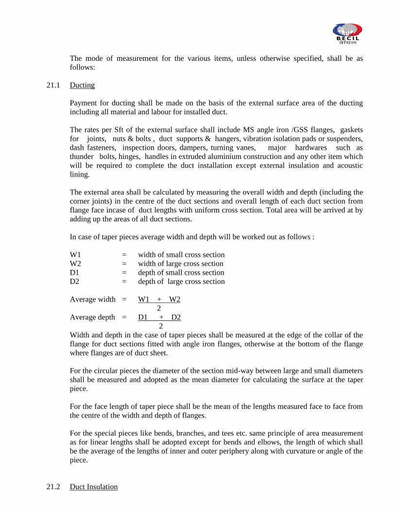
The mode of measurement for the various items, unless otherwise specified, shall be as
follows:
21.1 Ducting
Payment for ducting shall be made on the basis of the external surface area of the ducting
including all material and labour for installed duct.
The rates per Sft of the external surface shall include MS angle iron /GSS flanges, gaskets
for joints, nuts & bolts , duct supports & hangers, vibration isolation pads or suspenders,
dash fasteners, inspection doors, dampers, turning vanes, major hardwares such as
thunder bolts, hinges, handles in extruded aluminium construction and any other item which
will be required to complete the duct installation except external insulation and acoustic
lining.
The external area shall be calculated by measuring the overall width and depth (including the
corner joints) in the centre of the duct sections and overall length of each duct section from
flange face incase of duct lengths with uniform cross section. Total area will be arrived at by
adding up the areas of all duct sections.
In case of taper pieces average width and depth will be worked out as follows :
W1 = width of small cross section
W2 = width of large cross section
D1 = depth of small cross section
D2 = depth of large cross section
Average width = W1 + W2
2
Average depth = D1 + D2
2
Width and depth in the case of taper pieces shall be measured at the edge of the collar of the
flange for duct sections fitted with angle iron flanges, otherwise at the bottom of the flange
where flanges are of duct sheet.
For the circular pieces the diameter of the section mid-way between large and small diameters
shall be measured and adopted as the mean diameter for calculating the surface at the taper
piece.
For the face length of taper piece shall be the mean of the lengths measured face to face from
the centre of the width and depth of flanges.
For the special pieces like bends, branches, and tees etc. same principle of area measurement
as for linear lengths shall be adopted except for bends and elbows, the length of which shall
be the average of the lengths of inner and outer periphery along with curvature or angle of the
piece.
21.2 Duct Insulation
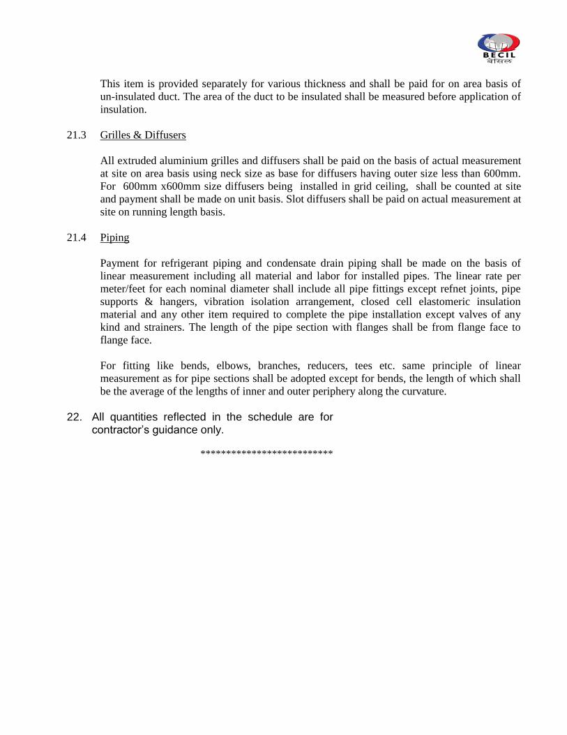
This item is provided separately for various thickness and shall be paid for on area basis of
un-insulated duct. The area of the duct to be insulated shall be measured before application of
insulation.
21.3 Grilles & Diffusers
All extruded aluminium grilles and diffusers shall be paid on the basis of actual measurement
at site on area basis using neck size as base for diffusers having outer size less than 600mm.
For 600mm x600mm size diffusers being installed in grid ceiling, shall be counted at site
and payment shall be made on unit basis. Slot diffusers shall be paid on actual measurement at
site on running length basis.
21.4 Piping
Payment for refrigerant piping and condensate drain piping shall be made on the basis of
linear measurement including all material and labor for installed pipes. The linear rate per
meter/feet for each nominal diameter shall include all pipe fittings except refnet joints, pipe
supports & hangers, vibration isolation arrangement, closed cell elastomeric insulation
material and any other item required to complete the pipe installation except valves of any
kind and strainers. The length of the pipe section with flanges shall be from flange face to
flange face.
For fitting like bends, elbows, branches, reducers, tees etc. same principle of linear
measurement as for pipe sections shall be adopted except for bends, the length of which shall
be the average of the lengths of inner and outer periphery along the curvature.
22. All quantities reflected in the schedule are for contractor‟s guidance only.
**************************
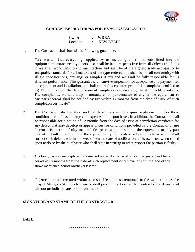
GUARANTEE PROFORMA FOR HVAC INSTALLATION
Owner : WDRA
Location : NEW DELHI
1. The Contractor shall furnish the following guarantee:
“We warrant that everything supplied by us including all components fitted into the
equipment manufactured by others also, shall be in all respects free from all defects and faults
in material, workmanship and manufacture and shall be of the highest grade and quality to
acceptable standards for all materials of the type ordered and shall be in full conformity with
all the specifications, drawings or samples if any and we shall be fully responsible for its
efficient performance. This guarantee shall survive inspection for acceptance and payment for
the equipment and installation, but shall expire (except in respect of the complaints notified to
us) 12 months from the date of issue of completion certificate by the Architect/Consultants.
The complaints, workmanship, manufacturer or performance of any of the equipment or
part/parts thereof shall be notified by fax within 12 months from the date of issue of such
completion certificate”.
2. The Contractor shall replace such of these parts which require replacement under these
conditions free of cost, charge and expenses to the purchaser. In addition, the Contractor shall
be responsible for a period of 12 months from the date of issue of completion certificate for
any defect that may develop or appear under the conditions provided by the Contractor or use
thereof arising from faulty material design or workmanship in the equivalent or any part
thereof or faulty installation of the equipment by the Contractor but not otherwise and shall
correct such defects within one week from the date of notification at his own cost when called
upon to do so by the purchaser who shall state in writing in what respect the portion is faulty.
3. Any faulty component replaced or renewed under the clause shall also be guaranteed for a
period of six months from the date of such replacement or removal of until the end of the
above mentioned period whichever is later.
4. If defects are not rectified within a reasonable time as mentioned in the written notice, the
Project Managers/Architects/Owners shall proceed to do so at the Contractor‟s risk and cost
without prejudice to any other right thereof.
SIGNATURE AND STAMP OF THE CONTRACTOR
DATE :
*********************
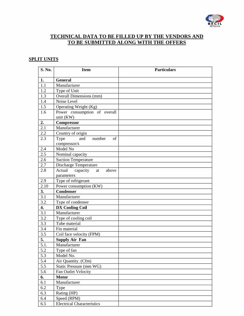
TECHNICAL DATA TO BE FILLED UP BY THE VENDORS AND
TO BE SUBMITTED ALONG WITH THE OFFERS
SPLIT UNITS
S. No.
Item Particulars
1. General
1.1 Manufacturer
1.2 Type of Unit
1.3 Overall Dimensions (mm)
1.4 Noise Level
1.5 Operating Weight (Kg)
1.6 Power consumption of overall
unit (KW)
2. Compressor
2.1 Manufacturer
2.2 Country of origin
2.3 Type and number of
compressor/s
2.4 Model No
2.5 Nominal capacity
2.6 Suction Temperature
2.7 Discharge Temperature
2.8 Actual capacity at above
parameters
2.9 Type of refrigerant
2.10 Power consumption (KW)
3. Condenser
3.1 Manufacturer
3.2 Type of condenser
4. DX Cooling Coil
3.1 Manufacturer
3.2 Type of cooling coil
3.3 Tube material
3.4 Fin material
3.5 Coil face velocity (FPM)
5. Supply Air Fan
5.1. Manufacturer
5.2 Type of fan
5.3 Model No.
5.4 Air Quantity. (Cfm)
5.5 Static Pressure (mm WG)
5.6 Fan Outlet Velocity
6. Motor
6.1 Manufacturer
6.2 Type
6.3 Rating (HP)
6.4 Speed (RPM)
6.5 Electrical Characteristics
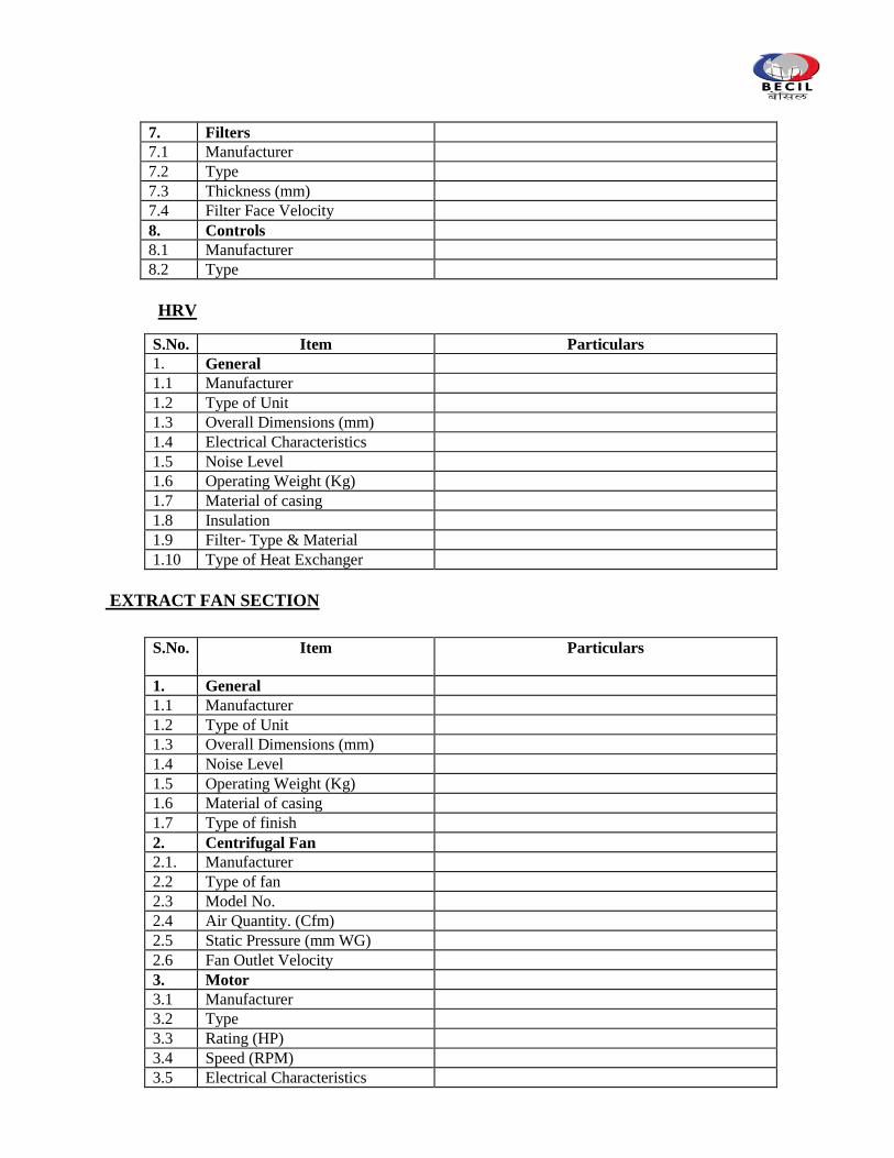
7. Filters
7.1 Manufacturer
7.2 Type
7.3 Thickness (mm)
7.4 Filter Face Velocity
8. Controls
8.1 Manufacturer
8.2 Type
HRV
S.No. Item Particulars
1. General
1.1 Manufacturer
1.2 Type of Unit
1.3 Overall Dimensions (mm)
1.4 Electrical Characteristics
1.5 Noise Level
1.6 Operating Weight (Kg)
1.7 Material of casing
1.8 Insulation
1.9 Filter- Type & Material
1.10 Type of Heat Exchanger
EXTRACT FAN SECTION
S.No. Item
Particulars
1. General
1.1 Manufacturer
1.2 Type of Unit
1.3 Overall Dimensions (mm)
1.4 Noise Level
1.5 Operating Weight (Kg)
1.6 Material of casing
1.7 Type of finish
2. Centrifugal Fan
2.1. Manufacturer
2.2 Type of fan
2.3 Model No.
2.4 Air Quantity. (Cfm)
2.5 Static Pressure (mm WG)
2.6 Fan Outlet Velocity
3. Motor
3.1 Manufacturer
3.2 Type
3.3 Rating (HP)
3.4 Speed (RPM)
3.5 Electrical Characteristics
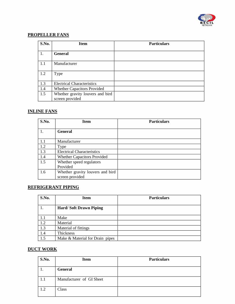
PROPELLER FANS
S.No. Item
Particulars
1. General
1.1 Manufacturer
1.2 Type
1.3 Electrical Characteristics
1.4 Whether Capacitors Provided
1.5 Whether gravity louvers and bird
screen provided
INLINE FANS
S.No. Item
Particulars
1. General
1.1 Manufacturer
1.2 Type
1.3 Electrical Characteristics
1.4 Whether Capacitors Provided
1.5 Whether speed regulators
Provided
1.6 Whether gravity louvers and bird
screen provided
REFRIGERANT PIPING
S.No. Item
Particulars
1. Hard/ Soft Drawn Piping
1.1 Make
1.2 Material
1.3 Material of fittings
1.4 Thickness
1.5 Make & Material for Drain pipes
DUCT WORK
S.No. Item Particulars
1. General
1.1 Manufacturer of GI Sheet
1.2 Class
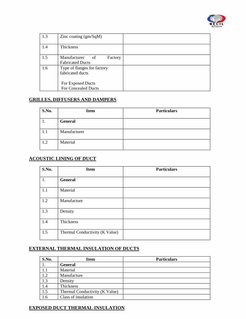
1.3 Zinc coating (gm/SqM)
1.4 Thickness
1.5 Manufacturer of Factory
Fabricated Ducts
1.6 Type of flanges for factory
fabricated ducts
For Exposed Ducts
For Concealed Ducts
GRILLES, DIFFUSERS AND DAMPERS
S.No. Item Particulars
1. General
1.1 Manufacturer
1.2 Material
ACOUSTIC LINING OF DUCT
S.No. Item
Particulars
1. General
1.1 Material
1.2 Manufacture
1.3 Density
1.4 Thickness
1.5 Thermal Conductivity (K Value)
EXTERNAL THERMAL INSULATION OF DUCTS
S.No. Item Particulars
1. General
1.1 Material
1.2 Manufacture
1.3 Density
1.4 Thickness
1.5 Thermal Conductivity (K Value)
1.6 Class of insulation
EXPOSED DUCT THERMAL INSULATION
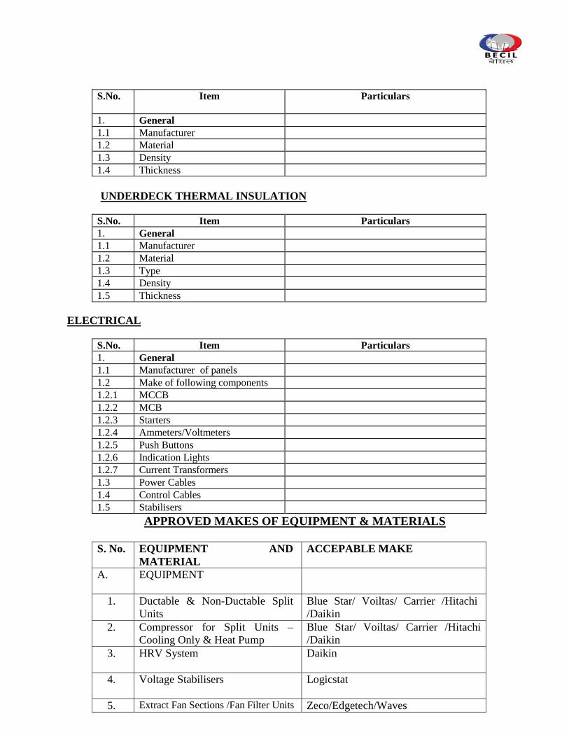
S.No. Item Particulars
1. General
1.1 Manufacturer
1.2 Material
1.3 Density
1.4 Thickness
UNDERDECK THERMAL INSULATION
S.No. Item Particulars
1. General
1.1 Manufacturer
1.2 Material
1.3 Type
1.4 Density
1.5 Thickness
ELECTRICAL
S.No. Item Particulars
1. General
1.1 Manufacturer of panels
1.2 Make of following components
1.2.1 MCCB
1.2.2 MCB
1.2.3 Starters
1.2.4 Ammeters/Voltmeters
1.2.5 Push Buttons
1.2.6 Indication Lights
1.2.7 Current Transformers
1.3 Power Cables
1.4 Control Cables
1.5 Stabilisers
APPROVED MAKES OF EQUIPMENT & MATERIALS
S. No. EQUIPMENT AND
MATERIAL
ACCEPABLE MAKE
A. EQUIPMENT
1. Ductable & Non-Ductable Split
Units
Blue Star/ Voiltas/ Carrier /Hitachi
/Daikin
2. Compressor for Split Units –
Cooling Only & Heat Pump
Blue Star/ Voiltas/ Carrier /Hitachi
/Daikin
3. HRV System
Daikin
4. Voltage Stabilisers Logicstat
5. Extract Fan Sections /Fan Filter Units Zeco/Edgetech/Waves
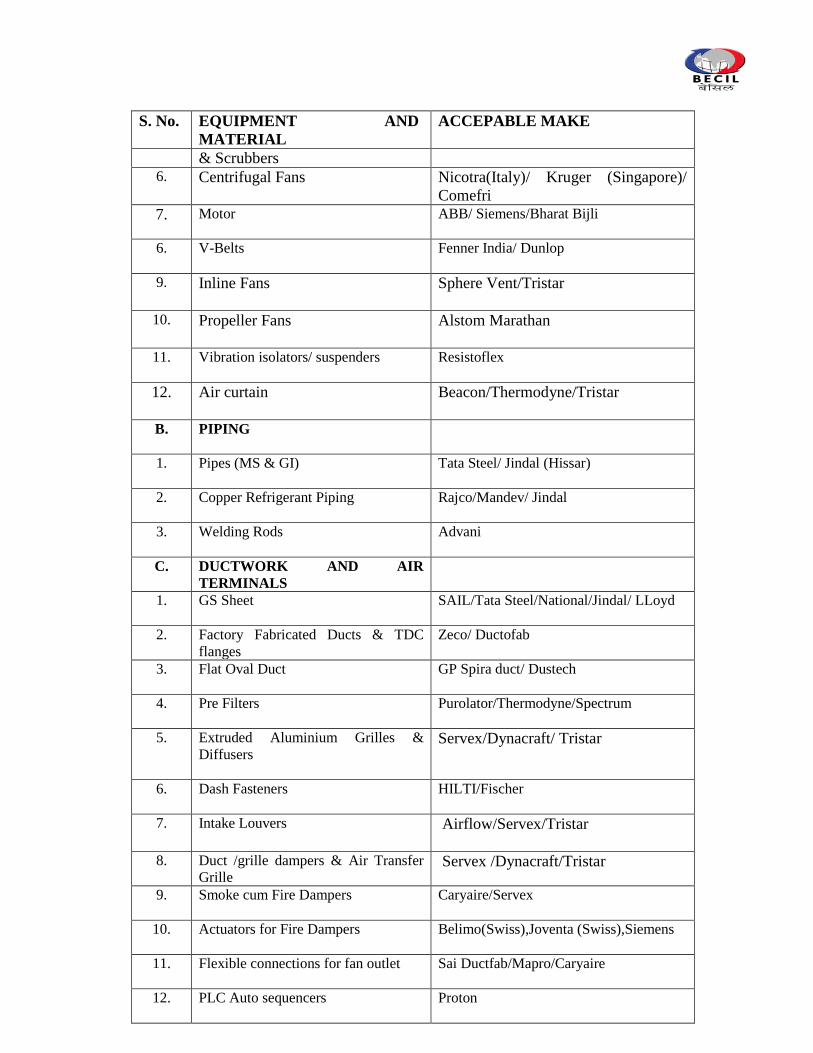
S. No. EQUIPMENT AND
MATERIAL
ACCEPABLE MAKE
& Scrubbers
6. Centrifugal Fans Nicotra(Italy)/ Kruger (Singapore)/
Comefri
7. Motor
ABB/ Siemens/Bharat Bijli
6. V-Belts
Fenner India/ Dunlop
9. Inline Fans Sphere Vent/Tristar
10. Propeller Fans Alstom Marathan
11. Vibration isolators/ suspenders
Resistoflex
12. Air curtain
Beacon/Thermodyne/Tristar
B. PIPING
1. Pipes (MS & GI) Tata Steel/ Jindal (Hissar)
2. Copper Refrigerant Piping Rajco/Mandev/ Jindal
3. Welding Rods
Advani
C. DUCTWORK AND AIR
TERMINALS
1. GS Sheet SAIL/Tata Steel/National/Jindal/ LLoyd
2. Factory Fabricated Ducts & TDC
flanges
Zeco/ Ductofab
3. Flat Oval Duct
GP Spira duct/ Dustech
4. Pre Filters Purolator/Thermodyne/Spectrum
5. Extruded Aluminium Grilles &
Diffusers
Servex/Dynacraft/ Tristar
6. Dash Fasteners
HILTI/Fischer
7. Intake Louvers Airflow/Servex/Tristar
8. Duct /grille dampers & Air Transfer
Grille Servex /Dynacraft/Tristar
9. Smoke cum Fire Dampers Caryaire/Servex
10. Actuators for Fire Dampers Belimo(Swiss),Joventa (Swiss),Siemens
11. Flexible connections for fan outlet Sai Ductfab/Mapro/Caryaire
12. PLC Auto sequencers Proton
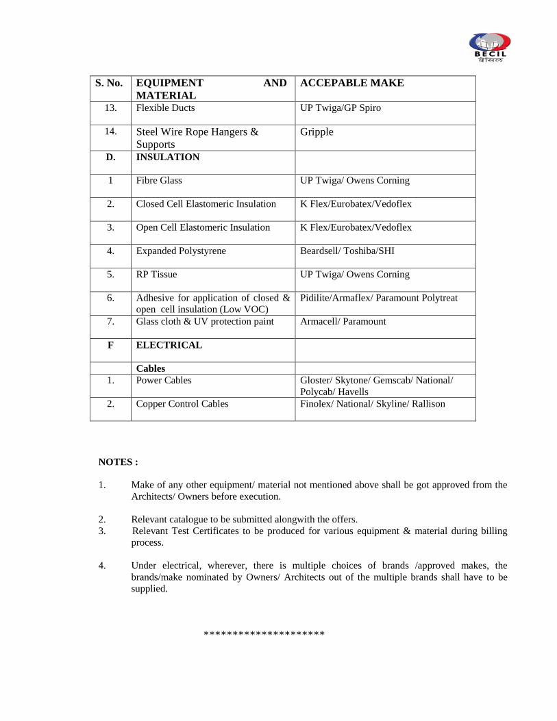
S. No. EQUIPMENT AND
MATERIAL
ACCEPABLE MAKE
13. Flexible Ducts UP Twiga/GP Spiro
14. Steel Wire Rope Hangers &
Supports
Gripple
D. INSULATION
1 Fibre Glass
UP Twiga/ Owens Corning
2. Closed Cell Elastomeric Insulation
K Flex/Eurobatex/Vedoflex
3. Open Cell Elastomeric Insulation
K Flex/Eurobatex/Vedoflex
4. Expanded Polystyrene
Beardsell/ Toshiba/SHI
5. RP Tissue
UP Twiga/ Owens Corning
6. Adhesive for application of closed &
open cell insulation (Low VOC)
Pidilite/Armaflex/ Paramount Polytreat
7. Glass cloth & UV protection paint
Armacell/ Paramount
F ELECTRICAL
Cables
1. Power Cables
Gloster/ Skytone/ Gemscab/ National/
Polycab/ Havells
2. Copper Control Cables
Finolex/ National/ Skyline/ Rallison
NOTES :
1. Make of any other equipment/ material not mentioned above shall be got approved from the
Architects/ Owners before execution.
2. Relevant catalogue to be submitted alongwith the offers.
3. Relevant Test Certificates to be produced for various equipment & material during billing
process.
4. Under electrical, wherever, there is multiple choices of brands /approved makes, the
brands/make nominated by Owners/ Architects out of the multiple brands shall have to be
supplied.
*********************
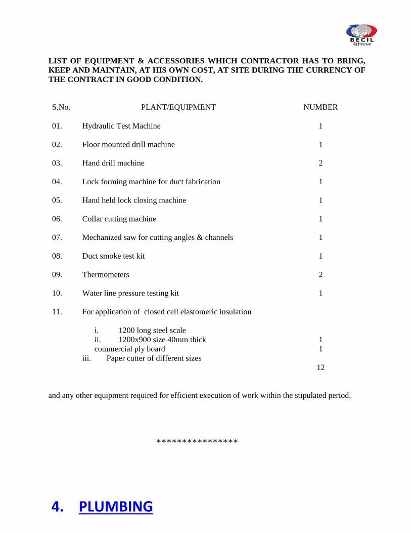
LIST OF EQUIPMENT & ACCESSORIES WHICH CONTRACTOR HAS TO BRING,
KEEP AND MAINTAIN, AT HIS OWN COST, AT SITE DURING THE CURRENCY OF
THE CONTRACT IN GOOD CONDITION.
S.No. PLANT/EQUIPMENT NUMBER
01.
Hydraulic Test Machine 1
02. Floor mounted drill machine 1
03. Hand drill machine 2
04. Lock forming machine for duct fabrication 1
05. Hand held lock closing machine 1
06. Collar cutting machine 1
07. Mechanized saw for cutting angles & channels 1
08. Duct smoke test kit 1
09. Thermometers 2
10. Water line pressure testing kit 1
11. For application of closed cell elastomeric insulation
i. 1200 long steel scale
ii. 1200x900 size 40mm thick
commercial ply board
iii. Paper cutter of different sizes
1
1
12
and any other equipment required for efficient execution of work within the stipulated period.
****************
4. PLUMBING
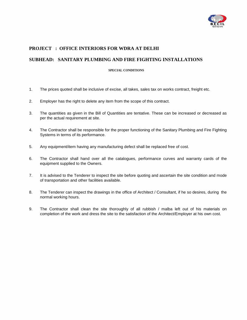
PROJECT : OFFICE INTERIORS FOR WDRA AT DELHI
SUBHEAD: SANITARY PLUMBING AND FIRE FIGHTING INSTALLATIONS
SPECIAL CONDITIONS
1. The prices quoted shall be inclusive of excise, all takes, sales tax on works contract, freight etc.
2. Employer has the right to delete any item from the scope of this contract.
3. The quantities as given in the Bill of Quantities are tentative. These can be increased or decreased as
per the actual requirement at site.
4. The Contractor shall be responsible for the proper functioning of the Sanitary Plumbing and Fire Fighting
Systems in terms of its performance.
5. Any equipment/item having any manufacturing defect shall be replaced free of cost.
6. The Contractor shall hand over all the catalogues, performance curves and warranty cards of the
equipment supplied to the Owners.
7. It is advised to the Tenderer to inspect the site before quoting and ascertain the site condition and mode
of transportation and other facilities available.
8. The Tenderer can inspect the drawings in the office of Architect / Consultant, if he so desires, during the
normal working hours.
9. The Contractor shall clean the site thoroughly of all rubbish / malba left out of his materials on
completion of the work and dress the site to the satisfaction of the Architect/Employer at his own cost.
TECHNICAL SPECIFICATIONS
1. SCOPE OF WORK
This part of the Contract shall include the following services:
i) Supply & Installation of sanitary fixtures and faucets etc
ii) Supply & Installation of internal water supply distribution network
III) Supply & Installation of above ground drainage system
iii) Supply & Installation of Fire Fighting Accessories and painting FHC door and hose
reel drum
iv) Supply & Installation of Portable Fire Extinguishers.
v) Identification and labeling of the pipe work under the scope of this contract.
vi) Testing and commissioning the complete sanitary plumbing and fire fighting systems including the existing installation.
The Tenderer shall include for the supply, unless otherwise mentioned, delivery, installation, connection, commissioning and testing of all materials and equipment to provide a complete sewerage, drainage and water supply installation and fire fighting installation as described hereunder. It is proposed to use the dismantled material to the extent possible. While quoting the installation rates for such items, the tenderer must include for cleaning, oiling/greasing, new gaskets, washers, nuts & bolts etc.
2.0 GENERAL
2.1 STATUTORY REGULATIONS AND APPROVALS
All works shall be carried out only by those Contractors who are licensed by the concerned local authorities to execute this type of work. It shall be the responsibility of the Contractor to comply with the regulations as laid down by the local authorities.
2.2 SITE CONDITIONS
It is assumed that before tendering the Contractor would have visited the site and familiarized himself with all the local conditions and means of transportation and
communications. No claim of whatsoever nature would be entertained at a later date on account of the Contractor's ignorance of the local conditions.
2.3 STANDARD AND CODES OF PRACTICE
The work shall be carried out as per the enclosed Specifications of Work and the construction drawings to be issued from time to time. These specifications shall be read in conjunction with CPWD specifications, National Building Code 2005, relevant Codes of Practice and Standards as issued by Bureau of Indian Standards (B.I.S. - all with the latest amendments) wherever applicable.
2.4 WORKMANSHIP
All the work shall be carried out in a workmanship like manner and as per the best practices of the trade.
2.5.0 DRAWINGS AND DOCUMENTS
2.5.1 General
ii) The Drawings are intended as a guide to the firms tendering and give approximate positions of pipes, conduits, cable runs and/or equipment only and in measuring from these drawings, the Tenderer must make due and proper allowance for all necessary diversions from the straight line, rises or falls as may be required for the proper execution of the works.
Detail drawings in all cases shall be worked to in preference to those of a more
general nature and figured dimensions where indicated shall be followed in preference to scale.
Where necessary, the exact positions of plant and/or equipment will be decided by
the issue of further drawings, but no claim for extra payment due to insufficient information on this scope will be entertained.
In any case of doubt as to the interpretation of either Drawings and/or Specification,
the Tenderer must refer the matter to the Employer prior to the submission of his Tender.
iii) It is to be clearly understood that this Tender is to be absolutely inclusive for the
proper completion of the whole of the works specified to the true intent and meaning of the specification and/or Drawings and the description therein contained shall be read conjointly and together and no error, inconsistency, discrepancy in the Drawings and/or Specification will relieve the Contractor of his obligations to include for an hand-over the work in the true meaning and intent of the Specification and/or Drawings, complete in every respect.
Should any portion of the works which would reasonably and obviously be inferred as necessary for the installation as a whole not be expressly specified, the
Contractor shall provide and execute such work as part of the Contract and shall not be entitled to any extra payment of that account.
iv) The Contract Drawings and such other drawings as may be furnished to the
Contractor during the progress of the Works shall be considered as illustrating between the Drawings and the Specification, the Contractor shall execute the work in accordance with the decision of the Employer. If modifications are necessary, the Contractor shall submit modifications to the Employer for approval before such modifications are executed.
v) All Drawings and Specification are the property of the Employer. vi) The Contractor will be required to give and obtain all necessary site and other
particulars and to agree such details with the Employer. The Contractor must also obtain details of any other Contractor's work affected by his work and shall work in close co-operation with all such firms or persons concerned.
vii) The Contractor shall be responsible for any damage caused to buildings and
contents and works by reason of, arising out of, or incidental to, or in connection with the execution of any work in the Contract Documents.
The Contractor shall permit nothing to be done which may injure the stability of the
Works, or existing buildings and no cutting through floors or walls will be allowed other than where required by the Drawings, without the sanction of the Employer.
viii) The Contractor shall submit to the Employer for approval, before the work is commenced, a copy of all working details and installation drawings.
These drawings must be submitted by the Contractor as soon as possible after the
order is placed to give ample time for all parties concerned to study and comment thereon.
ix) The work described on any working drawings submitted shall be carefully checked
by the Contractor for all clearances, field conditions, maintenance of architectural conditions and proper co-ordination with all trades on the job. To this end, the Contractor, during the construction drawing stage, shall ensure that he co-ordinates drawings of all other trades that might interfere with the proper installation of his work. No payment shall be made for any variations or alterations on site due to lack of knowledge of other trades. Any unresolved conflict between trades shall be referred to the Employer.
The equipment layout is to be detailed on the drawings, showing the exact method of
installing and clearly illustrating components to be used in making all connections. x) Pipework drawings must be fully detailed, showing all pipework in double line and
indicating the precise size of fittings, valves and equipment, position of hanger
supports with reference numbers must be indicated and a large scale detail must be given, showing the type and method of installation of each type of hanger. A schedule is to be included on each drawing, showing details of the type of hanger fixings and references number for each type.
All general layout drawings shall be drawn 1/50 scale, unless agreed otherwise with
the Employer. xi) The Contractor shall provide a detailed programme incorporating working drawing
production, which can be read in conjunction with the building construction programme.
xii) The Contractor shall prepare schedules and drawings showing precise details of
holes in concrete, block works etc., base frames or support required and the like. The schedules shall show in detail the builder‟s work required to be performed by all other trades for the mechanical and electrical installations. These drawings and schedules, in an approved form, must be submitted to the Employer well in advance and his approval must be obtained before any structural work requiring holes or other modifications is constructed.
xiii) Signed and approved drawings will not be departed from unless a signed variation or
omission certificate is issued in writing by the Employer. Drawings returned to the Contractor for alteration or amendment shall be re-submitted to the Employer for approval.
Amended or altered drawings shall show the nature of the amendment or alteration
in a revision block on the drawing, together with the revision number or letter and the date of the revision.
xiv) Should the Contractor prove unable to produce satisfactory "Working Drawings" or
be unable to produce drawings to conform to the progress of the work, the Employer reserves the right to take whatever steps are necessary to have drawings undertaken by others and debit the Contractor's account.
Any decision taken by the Employer to have working drawings produced elsewhere
will not relieve the Contractor of his contractual obligations and the Contractor must provide to the Employer all necessary details, physical dimensions, descriptive literature, etc., of all equipment to be incorporated on drawings within 10 days of a request from the Employer.
2.5.2 Manufacturers' Data
i) Manufacturers' performance data, certified factory drawings of plant and machinery, giving full information as to capacity, dimensions, materials and all information pertinent to the adequacy of the proposed equipment shall be submitted for approval.
Manufacturer names, sizes, catalogue numbers and/or samples of all materials shall
be submitted for approval. Submittals and working drawings should, as far as possible be complementary so
that drawings and submittals can be cross checked. ii) The copy of the placement of order with the manufacturer of the equipment shall be
submitted to the Employer for his approval and must be accompanied by relevant drawings, technical data, catalogues and samples, where data, certified drawings or other required information is not available until after orders have been placed, the Employer will give provisional approval until all requested drawings and information have been supplied to the Employer and approved by him. It is the Contractor's responsibility to ensure that all necessary information is supplied to the Employer in accordance with the progress of the work.
2.5.3 Operating and Maintenance Manual
i) The Contractor shall furnish six copies in bound form of an instruction manual containing all information applicable to this section of the Works. This manual is to be similar in design and content to those to be provided under other services.
The manual shall contain a comprehensive written description of the Works, outlining
the operation of the systems and maintenance procedures.
2.5.4 “As Installed " Drawings
i) The Contractor shall arrange to keep on Site a full set of drawings showing the progress of the Works, which must be kept upto date.
The Contractor shall keep a record as the work proceeds of any work installed not in
accordance with the drawings. On completion of the Works the Contractor shall supply three clear coloured prints of each applicable drawing, showing the exact position of all apparatus, pipe lines, services, control valves, switchgear, etc., together with diagrams, schedules, etc. to the Employer's requirements and in addition one complete set of plastic negatives and soft copy on compact disk (CD).
The word "AS INSTALLED DRAWINGS" shall be clearly indicated on all drawings adjacent to the title block.
2.6 DISCREPANCIES IN THE DRAWINGS
Should there be any discrepancy due to in-complete description, ambiguity or omission in the drawings and other documents relating to this Contract found by the Contractor either before starting the work or during execution or after completion, the same shall be immediately brought to the attention of the Architect/Consultant and his decision would be final and binding on the Contractor.
2.7 INSTRUMENTS FOR MEASUREMENT AND TESTING
The Contractor shall provide, free of cost, all equipments, instruments, labour and all other allied assistance required by the Owner/Architect or their representatives for measurement and testing of the works.
2.8 CO-ORDINATION WITH OTHER TRADES
The Contractor shall be responsible for coordinating this work with works of other trades sufficiently ahead of time to avoid unnecessary hold ups. Hangers, sleeves, recesses etc. shall be left in time as the work proceeds.
2.9 PROTECTION
All work shall be adequately protected, to the satisfaction of the Owner/Architect, so that the whole work is free from the damage throughout the period of construction upto the time of handing over.
Special care must be taken to prevent damage and scratching of all fittings and fixtures. Tool marks on exposed fixtures shall not be accepted. Protective paper on fixtures shall be removed with hot water only at the final completion of the work.
Before handing over the work, the Contractor shall clean all elements of the complete installation, remove plasters, splashes, stickers, rust stains and all other foreign matter and leave every part in acceptable condition and ready for use to the satisfaction of the Owner/Architect.
3.0 SOIL, WASTE AND VENT PIPEWORK
3.1 GENERAL
It is proposed to use both centrifugally cast (spun) iron pipes and fittings UPVC pipes &
fittings for soil, waste, vent and rain water pipe work. Reference shall be made to the drawings for ascertaining the use of a particular material for any specific area. In case of any doubt or ambiguity, the direction shall be taken from the Owner/Architect.
3.2.0 CAST IRON PIPES AND FITTINGS
3.2.1 Specifications
Wherever specified cast iron pipes for soil, waste, vent and rain water system, centrifugally cast (spun) iron pipes & fittings conforming to IS:3989-1979 shall be used for soil, waste and vent pipework unless specified otherwise. Pipes and fittings with irregular bore, blow holes and other manufacturing defects shall not be allowed to be used for work. All fittings shall be of the degree specified or as required at site. All pipework shall be carried out in workmanship like manner following CPWD Specifications in general. However, 50mm dia cast iron pipes can be sand cast iron conforming to IS:1729-1979.
3.2.2 Fixing
All vertical pipes shall be fixed by M.S. Clamps truly vertical. Branch pipes shall be connected to the stack at the same angle as that of the fittings. No collars shall be used on vertical stacks. Each stack shall be terminated at top with a cowl (Terminal Guard).
Horizontal pipes running along ceiling shall be fixed on structural adjustable clamps of special design shown on the drawings or as directed. Horizontal pipes shall be laid to uniform slope and the clamps adjusted to the proper levels so that the pipes fully rest on them.
Contractor shall provide all sleeves, openings, hangers, inserts during the construction. He shall provide all necessary information to the building Contractor for making such provisions in the structure as necessary. All damages shall be made good to restore the surfaces if the above are not incorporated in time and provided afterwards by cutting walls and slabs..
3.2.3 Cast Iron Floor Traps
Floor traps shall be cast iron deep seal type „P‟ or „S‟ traps with a minimum seal of 50 mm. They shall be with or without vent.
3.2.4 Floor Trap Extension Piece
Wherever mentioned, flow trap shall be provided with G.I. extension piece. Length of the extension piece shall be as per the site conditions. On this extension piece, sockets of suitable diameters shall be welded at the required angle as per the drawing and site conditions. This extension piece shall be lead /epoxy sealant caulked into the collar of `P'/`S' trap.
3.2.5 Installation of Cast Iron, Soil, Waste and Ventilation Pipe Work
Gradient
The gradient of a horizontal branch should not be flatter than 1 in 50 and not steeper than 1 in 10.
Layout
The pipework in branch connections should always be arranged to allow free drainage of the system. Connections to main or branch pipes should be so arranged as to prevent cross flow from one appliance to another . Connections should be made with an easy sweep in the direction of flow.
Joint
All joints in pipe work and all pipe work to appliances should be made in such a manner as to be air-tight and water tight and to remain so during use.
Bends
Bends should be of long radius where practicable. In the case of bends in the bottom most pipes, they should necessarily be of long radius and should be preferably be made of 135 degree (1/8) bends.
Access
Ample provision should be made for excess to all pipe work and embedding of joint in walls should be avoided as far as possible. All tee and cross pieces shall be with excess doors. Wherever instructed by the Consultant, the bends with excess doors shall also be provided. The bottom most pipe of every soil and waste stack shall be provided with an excess piece at a height not more than 30 cm from the finished ground level.
Soil pipes
Soil Pipes, whether inside or outside the building, shall not be connected with any rain water pipe and there shall not be any trap in such soil pipe or between it and any drain with which it is connected.
Ventilating Pipe
a) Ventilating pipes should be so installed that water cannot be retained in them. They should be fixed vertically. Whenever possible, horizontal runs should be avoided. Ventilating pipe shall be carried to such a height and in such a position as to afford by means of the open end of such pipe or vent shift, a safe outlet of foul air with the least possible nuisance.
b) The upper end of the main ventilating pipe may be continued to the open air above
roof level as separate pipe or it may joint the MSP and/or MWP above the floor level of the highest appliance. Its lower end may be carried down to join the drain at a point where air relief may always be maintained.
c) Branch ventilating pipes should be connected to the top of the BSP and BWP between 75 mm and 450 mm from the crown of the trap.
d) The ventilating pipe shall always be taken to a point 150 cm above the level of the
leaves or flat roof or terrace parapet whichever is higher or the top of any window within a horizontal distance of 3 m. The least dimension shall be taken into account. The upper end of every ventilating pipe shall be protected by means of a cowl.
3.2.6 Concrete Encasing
All soil and waste pipes horozontally laid in toilets (but not in open ducts) shall be covered with 75 mm thick cement concrete 1:2:4 all around. Encasement of such pipes shall be done after testing of pipes and shall be paid extra.
3.2.7 Painting
All pipes in ducts and exposed position shall be painted with minimum two coats of enamel paint of approved shade and quality over a coat of primer. Pipes under floor or in chases need not be painted.
3.3.0 U.P.V.C. PIPES AND FITTINGS
3.3.1 Specifications
Wherever specified, internal foul drainage pipework and fittings shall be of UPVC conforming to IS:13592. Class B. Pipes of sizes 75mm, 110 mm & 160 mm dia shall be suitable for pushfit joints unless otherwise specified. Pipes of other sizes shall be suitable for solvent cement joints. Fittings in general shall be injection moulded and suitable for soil, waste and rain water drainage application. However, specials can be fabricated using pipes and fittings described above. All pipework fittings and accessories shall be installed strictly in accordance with the manufacturer's recommendations. The Contractor shall ensure that the UPVC pipes are of a sufficiently high temperature rating to withstand the environmental conditions.
3.3.2 U.P.V.C Pipework Installations
During the installation of internal drainage and waste system, the Contractor shall make due allowance for the expansion of UPVC and polypropylene pipework and fittings during normal working conditions. Further allowance shall be made for solvent weld jointing of the above materials with regard to temperature and humidity. The jointing of vertical pipes and fittings can be with pushfit type joints with natural rubber gasket of high standard. The horizontal pipes shall be provided with solvent cement joints. Wherever required the pushfit type joints shall be further sealed with expandable type silicon sealant.
The bore of all pipework shall be smooth and free from all burrs or obstructions; bends wherever possible shall be of the long radius type. All connections between soil drainage, vent, waste or fixtures shall be made with approved connectors. The termination at high level of all vent stacks shall be carried out with a vent guard.
All fixtures and fittings draining into the internal drainage installations shall be fitted with traps. In case of traps for sanitary fixtures e.g., hand wash basins, sinks etc., shall be of the deep seal type having a water seal of 50 mm.
Traps to sanitary fittings shall have deep seals of at least 50 mm depth of water and shall have inlet sizes as follows: Wash Basins -32 mm (ID)
Sinks -40 mm (ID) Bath Tubs -40 mm (ID)
Pipework shall be fixed accurately to approved falls, the gradient shall be consistent and pipework shall follow a true line. Allowance shall be made for the rodding of the whole installation in addition to which, at all changes of direction, a rodding eye shall be installed.
The pipework shall be fixed to the walls using standard PVC coated mild steel or PVC brackets of a screw-on type recommended by the manufacturers. The maximum spacing between the supports shall be as follows:
Pipe Diameter Horizontal Vertical
32 mm 1.00 M 1.25 M
40 mm 1.00 M 1.25 M
50 mm 1.00 M 1.25 M 63 mm 1.00 M 1.25 M 75 mm 1.25 M 2.00 M 110 mm 1.25 M 2.00 M 163 mm 1.25 M 2.00 M
The Contractor shall provide access or rodding eyes wherever required to provide full access to the system. The rodding eye shall also be provided at the foot of all vertical stacks at the point of connection to the underground drain pipe.
Access doors in suspended pipework within 0.5 M of the sofit shall not face upwards but be located on the side or underneath the pipe.
Where traps, access branches and access doors are located above false ceiling, removable panels shall be provided.
Soil and waste ventilation pipes passing through roofs shall be weather proofed to the satisfaction of the Owner.
The vent pipes shall be carried upto a minimum height from finished roof level of 500 mm to prevent any pressure fluctuations in the stack due to wind effect.
Connections to the outlets of the water closets shall be made by the use of proprietary UPVC WC connectors. Generally vent and anti-syphonage pipes and fittings shall be installed above the flood level of the fitting wherever possible.
The whole of the installation shall be tested in accordance with the requirements of CPWD and Bureau of Indian Standards specification. All tests shall be to the full satisfaction of the Owner.
3.3.3 U.P.V.C. Floor Traps
Floor traps shall be UPVC deep seal type „P‟ traps with a minimum seal of 50 mm. They shall be with or without vent as required.
3.3.4 U.P.V.C. Floor Trap Extension Piece
Wherever mentioned, floor trap shall be provided with UPVC extension piece. Length of the extension piece shall be as per the site conditions. Extension piece shall be formed out of boss pipe as per standard details and drawings.
3.4 CLEAN OUTS
Clean outs shall be provided in the soil, waste and vent pipework as per the standard details wherever shown on the drawings and wherever required by the Owner.
3.5 VENTILATION SYSTEM
i) Ventilating pipes shall project through walls or roofs to vent into the open air at the points shown on the drawings. The ventilation pipes shall be fitted with balloon at the top.
ii) No vent terminal shall be directly beneath any door, window or other ventilating openings of the building, nor shall any such vent terminal be within 3 M horizontally of such an opening unless it is 60 cm above the top of such an opening.
iii) All vent and branch vent pipes shall be so graded and connected as to drip back to
the soil or waste pipe by gravity. Where vent pipes connect to horizontal soil or waste pipes, the vent pipes shall be
taken off above the centre line of the pipe. The vent pipes shall rise vertically or at an angle note more than 45o from the vertical to a point at least 150 mm above the floor level rim of the fixture it is venting before off-setting horizontally or before connecting to the branch vent.
v) A connection between a vent pipe and vent stack or stack vent shall made at least
150 mm above the flood level rim of the highest fixtures served by the vent. Horizontal vent pipes forming branch vents, relief vents or loop vents shall be at least 150 mm above the flood level rim of the highest fixture served.
3.6 PIPE SLEEVES
The Contractor shall install sleeves for all piping passing through slabs, beams, walls or any other building member. The sleeves shall be fixed in formwork before pouring of concrete. In foundations and walls the sleeves shall be properly grouted and the gap between sleeve and building member shall be made water tight. All sleeves shall be of PVC.
3.7 FLASHINGS
Pipes extending through roof shall be flashed with sheet lead, copper or other durable material to make the roof water tight. Complete shop drawing of method of dressing, as may be required by the Owner, shall be submitted for his approval prior to installation. Alternatively, upstands with precast concrete slab covers shall be provided as per standard detail.
3.8.0 JOINTING OF NON-SIMILAR MATERIALS
3.8.1 UPVC & Cast Iron Pipes
Wherever cast iron pipes and UPVC pipes are to be jointed, the spigot end of UPVC pipe
shall be jointed with socketed end of cast iron pipes. The length of spigot / plain end of UPVC pipe to be inserted in the socket of C.I. pipe shall be applied with PVC solvent cement and sprinklered with coarse sand end left for 24 hours. The joint shall be made with epoxy based (like Drip-Seal)
4.0 DOMESTIC WATER SERVICES
4.1 PIPE WORK
Where specified G.I. pipes for water supply inside and outside the building shall be genuine galvanised steel tubes conforming to IS:1239(Part-I)-1979 of specified grade with latest amendments. All fittings shall be malleable iron galvanised fittings conforming to IS:1879(Part-1 to 10)-1975 with latest amendments. All fittings shall have manufacturer's trade mark stamped on it. Fittings in G.I. pipe lines shall include elbows, tees, bends, reducers, nipples, union, bushes, G.I. clamps of approved design, G.I. flanges with 3 mm rubber insertion, nuts, bolts, washers, etc. All fittings shall be tested at manufacturer's work. Contractors may be required to produce certificate to this effect from the manufacturers. All pipework for water supply (both hot and cold) inside the building shall be carried out in a workmanship like manner following CPWD specifications in general. However the instead of white lead, thread lock cement shall be used for jointing the pipes and fittings. All materials shall be as specified in these specifications, bills of quantities and drawings. In case specifications of a material is not mentioned or not clear in the above, the reference shall be made to CPWD specifications and the relevant Indian Standards/codes.
CPVC PIPE WORK
Whereever specified, CPVC piping system for water supply system shall be SDR 11 rated and of approved makes. All pies and fittings shall comply with ASTM D 2846 standard.
All fittings shall be injection moulded. CPVC to CPVC jointing shall be fusion bonding type( Solvent Cement Type) using proprietary CPVC fusion compound. Transition fittings ( for making connections with valves, faucets, other appurtenances and non CPVC pipes) shall have brass insert having threads as per IS: 554. CPVC threaded fittings are not to be used.
All CPVC pipework for water supply (both hot and cold) inside the building shall be carried out in a workmanship like manner as per the manufacturer‟s recommendations. All materials shall be as specified in these specifications, bills of quantities and drawings. All the brass threaded adaptors and specials shall be jointed properly using Teflon tape. For storage, cutting, jointing, installing and testing of CPVC material, manufacturer`s instructions shall be strictly adhered to.
Solvent Cement : The jointing of pipes and plain fittings shall be by solvant cement of make and grade as specified and supplied by the manufacturer of CPVC piping system. It shall be insured that the solvent supplied is not used beyond the expiry period as mentioned on the packaging of the material.
HORIZONTAL SUPPORTS SPACING:
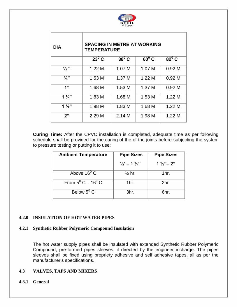
DIA
SPACING IN METRE AT WORKING TEMPERATURE
230 C 380 C 600 C 820 C
½ “ 1.22 M 1.07 M 1.07 M 0.92 M
¾” 1.53 M 1.37 M 1.22 M 0.92 M
1” 1.68 M 1.53 M 1.37 M 0.92 M
1 ¼” 1.83 M 1.68 M 1.53 M 1.22 M
1 ½” 1.98 M 1.83 M 1.68 M 1.22 M
2” 2.29 M 2.14 M 1.98 M 1.22 M
Curing Time: After the CPVC installation is completed, adequate time as per following schedule shall be provided for the curing of the of the joints before subjecting the system to pressure testing or putting it to use:
Ambient Temperature Pipe Sizes
½’ – 1 ¼”
Pipe Sizes
1 ½”– 2”
Above 160 C ½ hr. 1hr.
From 50 C – 160 C 1hr. 2hr.
Below 50 C 3hr. 6hr.
4.2.0 INSULATION OF HOT WATER PIPES
4.2.1 Synthetic Rubber Polymeric Compound Insulation
The hot water supply pipes shall be insulated with extended Synthetic Rubber Polymeric Compound, pre-formed pipes sleeves, if directed by the engineer incharge. The pipes sleeves shall be fixed using propriety adhesive and self adhesive tapes, all as per the manufacturer‟s specifications.
4.3 VALVES, TAPS AND MIXERS
4.3.1 General
Each valve body shall be marked with cast or stamped lettering giving the following informations :
a) The manufacturer‟s name or trade mark b) The size of the valve c) The guaranteed working pressure
Isolating valves on the water supply lines shall be full bore ball valve type for pipe diameters upto 50 mm. For 65 mm dia and 80 mm dia., these shall be gate valve type and diameters above 80 mm, `these shall be sluice valve type.
4.3.2 Float Valve
Float valves 50 mm and smaller shall be of brass, gun metal or other equally suitable corrosion resistant alloy in
accordance with IS:1703-1977 or approved equal. The float valves shall have copper or plastic floats suitably
reinforced to hold the threaded insert. The float valves fixed to the system shall be secured with backnuts.
4.3.3 Fullway Gate Valve
The valves shall be of quality approved by the Consultant/Owner and shall generally conform to IS:778-1971.
4.3.4 Full Way Ball Valve
The valves shall be of full bore type and of quality approved by the Consultant/Owner. The body and ball shall be of copper alloy and stem seat shall be of teflon.
4.3.5 Non-Return Valves
Non-return valves are to be IS:778-1984 manufactured from gun-metal or dezincification resistant brass.
4.3.6 Pressure Reducing Valve
The valve shall be suitable for water application and shall conform to relevant BIS standard. The valve should be installed in a vertical portion on horizontal line. In all cases, a stop valve should be installed in an easily accessible position on the inlet side of the pressure reducing valve. A safety valve and a pressure gauge must always be installed on the reduced pressure or outlet side of the pressure reducing valve. To avoid any dirt from entering the valve, it is advisable to fit a strainer on the inlet or high pressure line. The pressure reducing valve and accessories should conform to relevant BIS standard and of approved make.
4.3.7 Butterfly Valves
The valve shall of cast iron conforming to relevant IS:13095. The valve shall be of quality approved by
the consultant/Owner.
4.3.8 Taps and Mixers
Bib or mixer taps shall be fixed to sinks, lavatory basins, bathtubs and showers and as shown on the drawings and/or specified under the Sanitaryware schedule.
The Contractor must ensure that the installed taps and mixers are not damaged or mishandled till the handing over of the installation.
5.0 SANITARY FIXTURES AND FITTINGS
5.1 WORKMANSHIP
All Sanitaryware shall be fixed in neat workmanship like manner, true to level and plumb. Manufacturer's instructions shall be followed closely regarding installation and commissioning.
5.2 SANITARYWARE
All sanitaryware, shall be of approved make. All fittings shall be of first quality, free from wraps, cracks and glazing defects. All sanitaryware, fittings and fixtures shall be as shown in drawings and as described in details in schedule of quantities.
5.3 FIXING
All sanitarywares shall be installed in accordance with manufacturers printed instructions for conditions indicated and as required to obtain a rigid installation. The location of each fixture and the fixing method of ceramic fixtures shall be as shown on the drawings or as directed by the Owner. After all fittings have been mounted and are ready for use and before completion, all fittings furnished and mounted shall be thoroughly cleaned removing all plaster, stickers, rust, hair and other foreign matter or discolouration of fixtures, leaving each and every part in perfect condition and ready for use.
5.4 PROTECTION
The Contractor shall take adequate precautions to ensure that the sanitarywares are not damaged in any way before or after installation. Any piece of sanitaryware that is damaged shall be replaced at the Contractor's expense. The Contractor shall be responsible for checking sanitaryware on arrival at site. If any pieces of sanitarywares are
found to be damaged on arrival at site, the Contractor shall inform the Owner within two days. If the sanitarywares are delivered in damaged state, the Contractor shall refuse delivery of the damaged piece and shall request a replacement of the same.
5.5 TESTING
Just prior to handing over the building to the Owner, each piece of sanitaryware shall be tested. Each water closet shall be flushed twice and checked for leaks and any other defects by the Owner.
Each basin, bidet, bath and sink shall be filled to the overflow level and then after running
the water through the overflow for a minimum of 30 seconds, the plug shall be removed or opened. Each of the above mentioned fixtures shall be inspected for leaks and defects by the Owner.
Any defects or leaks shall be repaired or in the case of the defect being chips or cracks or
other visible damage, the fixture shall be replaced at the Contractor's expense. Any sanitaryware condemned by the Owner for any other reason shall be replaced at the Contractor's expense.
6.0 FIRE FIGHTING INSTALLATION
6.1.0 PIPE WORK
6.1.1 Materials
The pipe work shall be done in black mild steel pipes of `Heavy‟ grade conforming to IS:1239 (Part I)-1990 for upto 150 mm dia pipe and IS:3589-1991 for pipes above 150 mm dia. Fittings: All fittings upto 50 mm dia shall be black forged steel pipe fittings with threaded ends/ weldable socketed ends. Fittings above 50 mm dia shall be heavy duty mild steel with weldable ends. All fittings shall be conforming to relevant Indian Standards and shall have manufacturer's trade mark stamped on it. Fittings in M.S. pipe lines shall include elbows, tees, bends, reducers, nipples, union For welded joints forged steel fittings of approved type with “V” groove shall be used. Fabricated fittings shall not be permitted generally. However, if use of any fabricated fitting is found necessary by the Project Manager, fabrication of such fitting shall be taken up by the Contractor on the written directives of the Project Manager in a workshop following proper welding procedures. For fabricating a „Tee‟ connection pipes shall be drilled and reamed and joint only welded. Gas cutting of pipes shall not be permitted. Fabricated „Tee‟ out of M.S. plates shall not be used.
All fittings shall be tested at manufacturer's work. The Contractor may be required to produce certificate to this effect from the manufacturers. .
6.1.2 Jointing
The pipes and fittings upto 50 mm diameter shall be threaded joints using thread lock cement on the
threads. Joints for pipe and fittings above 50 mm diameter shall be welded joints. Care shall be taken to
remove any burr from the end of the pipe after cutting..
Welded Joints
The welding of pipes in the field should comply with IS:816, 1969. Electrodes used for welding should comply with IS:814, 1991.
Joints between M.S. pipes and fittings shall be made with pipes and fittings having “V” groove and welded with electrical resistance welding in an approved manner Butt welded joints shall not be acceptable. Care shall be taken to remove any burr from the end of the pipe after cutting. All welders must be fully qualified and proof of an operator‟s qualification shall be either the Contractor‟s record of suitable tests passed within the previous six months or tests made before the commencement of the work.
The Contractor must submit to the Owner the names of the welders who will be employed on the work, together with documentary evidence of their competency. Any welder considered by the Owner as not having the skill necessary for the work will at once be barred from further welding on the site or in the Contractor‟s workshop. The Owner may instruct the Contractor to cut out typical welded joints for inspection and the Contractor shall include for the removal of such pieces and re-making joints to the satisfaction of the Owner. The Contractor shall include in his Tender for the cost of removing all such pieces for inspection and re-making joints.
Care must be exercised by the Contractor to ensure that the welding flux does not project into the bore of the tube. All welds shall be good, clean metal, free from slag inclusions and porosity, of even thickness and regular contour, well fused with the parent metal and finished smooth. Where site welding is carried out in proximity to inflammable materials, the Contractor must take special precautions to protect the materials from risks of fire.
Testing of Welded Joints
The welded joints shall be tested in accordance with procedure laid down in IS:3600 (Part I) : 1985. One test specimen taken from at least one field joint out of any 10 shall be subjected to test.
If the results of the tensile test do not conform to the requirements specified, retests of two additional specimen from the same section shall be made, each of which shall conform to the required specifications. In case of failure of one or two, extensive gouging (scooping out) and repairing shall be carried out as directed by the authority. If internal pressures exceed 1.5 MPa (15 kgf/cm2), special attention should be given to the assembly of the pipe and the first run of weld. Non-destructive testing of the completed weld may be carried out on pipe-lines by radiographic (see IS:4853 : 1982) or ultrasonic method (see IS:4260, 1986)) as agreed upon between the Owner and the Contractor.
Screwed Joints
Joint for black steel pipes and fittings shall be metal to metal threaded joints using Teflon tape on the
threads.
Flanged Joint
M. S. Flanges shall be as per IS: 6392 and shall be faced. Rubber or asbestos gasket shall be
inserted between the joints.
Flange shall be provided on : a) Straight runs not exceeding 12-15 m on pipe lines 80 mm dia and above. b) Both ends of any fabricated fittings e.g. bends, tees etc. of 65mm or larger diameter. c) For jointing all type of valve, appurtenances, pumps, connection with other type of
pipes, to water tanks and other places necessary and required as per good for engineering practice.
Unions
Provide approved type of dismountable unions on pipes lines 65 mm and below in similar places as specified for flanges.
6.2 LAYING AND FIXING
a) Above Ground :
Exposed pipes on walls and ceilings shall be fixed with standard pattern G.I. holder bat clamps on angle iron frames embedded in walls or suspended from ceiling. The clamps shall be spaced at regular intervals in straight lengths as per the following table :-
Dia of Pipe Horizontal Length Vertical Length (mm) (M) (M)
25 2.4 3.0 32 2.7 3.0 40 3.0 3.6 50 3.0 3.6 65 3.6 4.5 80 3.6 4.5 100 4.0 4.5 150 4.5 5.4
b) Under Ground:
The trenches for the underground mains shall be 75 cm wide at top and excavated to a depth so that a minimum 1 meter of cover above the crown of the pipe is available after backfilling.
The pipes shall be evenly laid in the trenches after coating and wrapping as described hereinafter and covered with fine sand 150 mm all around. Any damage to coating and wrapping shall be made good before backfilling.
c) Protection of Underground Pipes:
The underground steel pipes shall be protected by coating and wrapping. The coating and wrapping shall be done, in general, as per IS:10221 - 1982.
First of all the pipes surface shall be roughly cleaned and dried before the application of primer, and shall be free of dirt, grease, oil, rust, scale or other foreign matter. After cleaning one uniform coat of coal tar primer shall be applied on the surface and one layer of glass fibre tissue shall be wrapped and simultaneously hot coat tar shall be applied. On this another layer of glass fibre tissue saturated with coal tar shall be wrapped with the simultaneous application of coal tar.
d) Anchor Blocks
Suitably designed anchor blocks in cement concrete to encounter excess thrust due to water hamer and high pressure should be provided at all bends, tees and such other locations as directed by the Engineer-in-charge. Exact location, design, size and mix of the concrete block shall be approved by the Architect / Consultant prior to the execution of the work.
6.3 VALVES
GENERAL
Each valve body shall be marked with cast or stamped lettering giving the following informations :
a) The manufacturer‟s name or trade mark b) The size of the valve c) The guaranteed working pressure
Isolating valves on the water supply lines shall be full bore ball valve type for pipe diameters upto 50
mm. For 65 mm dia and above these shall be butterfly valves.
6.3.1 Full Way Ball Valve
The valves shall be of full bore type and of quality approved by the Consultant/Owner. The body and
ball shall be of copper alloy and stem seat shall be of teflon.
6.3.2 Butterfly Valves
The valve shall of cast iron conforming to relevant IS:13095. The valve shall be of quality approved by the consultant/Owner.
6.3.3 Non-Return Valves
The valves shall be of quality approved by the Project Manager and shall generally conform to IS:778 - 1971.
6.3.4 Full Way Gate Valve
The full way valves shall be either of full bore brass ball valve or of heavy gunmetal conforming to
IS:778 - 1984.
6.3.5 Air Relief Valve
Air Valves are to be provided on all high points in the system. These shall be 25 mm dia screwed inlet cast iron single acting air valves.
6.3.6 DRAIN VALVE
Drain Valves are to be provided at all low points in the system for draining the water. These shall be 40 mm dia gun metal full way valve fixed on 40 mm dia black steel pipe.
6.3.7 PRESSURE SWITCHES
Pressure Switches shall be differential type for operation of all pumps and for the various duties and settings required. Pressure switches shall be for heavy duty operation and of approved make. All pressure switches shall be factory calibrated.
6.4.0 FIRE FIGHTING APPARATUS & FITTINGS
6.4.1 Internal Hydrants (Landing Valves)
i. The internal hydrant shall be single headed gunmetal landing valve with 63 mm dia outlet and 80 mm inlet (I.S:5290-1969), with individual shut off valves and cast iron wheels. Landing valve shall have flanged inlet and instantaneous type outlets as shown on the drawings.
ii. Instantaneous outlets for fire hydrants shall be of standard pattern approved
and suitable for fire brigade hoses.
iii. Contractor shall provide for each internal fire hydrant station two numbers of 63 mm dia. 15 mm long rubberised fabric linen hose pipes with gunmetal male and female instantaneous type coupling machine wound with G.I. wire (hose to I.S:636 type 2 and couplings to I.S:903 with I.S certification), fire hose reel, gunmetal branch pipe with nozzle I.S:903.
6.4.2 First Aid Fire Hose Reel
The First Aid Fire Hose Reels must be of type II and shall have 30 metre of 20 mm dia bore reinforced rubber hose fitted with shut-off gun metal nozzle. The hose reel shall be conforming to IS:884 - 1985.
6.4.3 Fire Hose Cabinet
The Fire Hose Cabinet of sizes suitable to accommodate equipment as specified in bill of quantities shall be fabricated of 16 gauge CRCA M.S. sheet and painted in fire red colour. Its door shall be hinged type having lock and reinforced glass panel.
The fire hose cabinet for yard hydrants shall be weatherproof type of size suitable to accommodate 2
nos. of 15M long 63mm diameter R.R.L. hoses with female & male gunmetal coupling and branch pipes.
Wherever masonry shaft is available to house equipment, only the glazed front panel is to
be fixed as required and as specified in bill of quantities.
6.4.4 SPRINKLER HEADS
Sprinkler heads shall be of gunmetal and quartz bulb type with a temperature rating of 68 deg.
Centigrade or as specified in the bill of quantities. These shall be of type and quality approved by the local
fire service and TAC.
6.5.0 AUTOMATIC SPRINKLER SYSTEM 6.5.1 Scope
The scope involves taping from existing riser and distribution of piping system shall be made as per
the drawing
7.0 TESTING AND COMMISSIONING
7.1 GENERAL
The Contractor shall be responsible for testing and commissioning the entire services installation described in these specifications and will demonstrate the operation of the system of the entire satisfaction of the Architect/Consultant and to the Owner approval. Work under this section shall be executed without any additional cost. The rates quoted in this tender shall be inclusive of the works given in this section. Contractor shall provide all tools, equipment, metering and testing devices required for the purposes. The entire fire fighting piping system shall be tested at minimum 14 kg/cm2 pressure. The test pressure shall the maintained for at least 2 hrs
.
7.2 METHOD OF TESTING
The test on various services shall be carried out as described herein as described in relevant Indiant Standards and British Standards and also as directed by the Owner.
The carrying out and recording of tests shall be agreed with the Architect/Consultant.
7.3 WATER FOR TESTING
Water for testing shall be obtained by the Contractor from an approved source. It shall be free from bacterial contamination, silt, grit, sand etc. After testing, the Contractor shall
satisfactorily dispose off all water, or it may be re used providing it is clean and is not contaminated.
7.4 TEST RECORDS
The Contractor shall be responsible for the keeping all records of tests and on completion shall provide records and reports of the tests in triplicate. All test records shall clearly identify the item of the test and must be signed by the Contractor‟s authorised representative and Owner.
7.5 UNSATISFACTORY WORKS
If the tests reveal unsatisfactory materials, installation or adjustment, the Contractor shall, at his own expense, carry out such alternations or replacements as may be necessary to rectify the defective work. The Contractor shall then repeat the tests as necessary to establish the satisfactory nature of the alterations or replacements.
7.6 TESTING AT WORKS
All plants and equipments shall be tested at manufacturer‟s works before despatch and
the test certificate in duplicate shall be forward to Architect/Consultant.
The Contractor shall similarly provide a set of manufacturer's certified test curves for any pump installed under the Contract. All tests shall be in accordance with the appropriate Indian Standards and British Standards as applicable.
7.7 ON SITE TESTING
The Contractor shall provide on site all the necessary instruments, plant, equipment, materials, water, electricity and labour necessary for carrying out the specified tests. All tests shall be carried out as required to meet the construction programme and the Contractor shall include for all necessary isolation and other works as may be required for testing the whole or parts of the installation. The Contractor shall also be responsible for re-testing, if necessary, until satisfactory tests are achieved.
7.8 TEST P RESSURES
Pipe Line Test Pressure Period Method
Water Mains, Fire Mains & Water Services.
5 kg/sq.cm. or maximum working pressure plus 50 percent which ever is greater.
2 Hours
Hydraulic Pressure Test
Underground Drainage
1.5 metres head of water at highest point
30 min. Hydraulic Test
Foul Drainage i) Not more than 4.5 M head 2 Hydraulic
above ground in any section Hours Test ii) 75 mm water gauge 3 min. Air Test
7.9.0 TESTING OF VARIOUS SERVICES
7.9.1 Water Services
Before the pipes for water supply are painted or covered they shall be tested to a hydraulic pressure
of 5 kg/sq.cm or maximum working pressure plus 50 percent whichever is greater. Pressure shall be
maintained for atleast 2 hours without appreciable drop in pressure. In addition to the sectional testing
of water supply pipes, the Contractor shall test the entire installation on completion of the job to the
entire satisfaction of the Owner. The Contractor shall rectify all leakages and restore damage done to
the building and furniture at his own cost.
7.9.2 Underground Drainage
The sewer and drain lines shall be tested for water tightness and straghtness as described below
i) Water Test: Pipes and joints shall be subjected to a test pressure of atleast 1.5 m head of water at
the highest point of the section under test. The test shall be carried out by suitably plugging the low end of the drain and filling the system with water. A knuckle bend shall be temporarily jointed in at the top end and a sufficient length of vertical pipe jointed to it so as to provide the required head. Or top end may be plugged with a connection to a hose ending in a funnel which could be raised or lowered till the required head is obtained and fixed suitably for observation.
ii) Test for Straightness and Observation. Sewer lines shall be tested for straightness :
a) By inserting at the high end of the sewer or drain a smooth ball of diameter 13 mm less than the pipe bore. In the basence of obstruction, such as yam or mortar projecting through the joints, the ball should roll down the invert of the pipe and emerge at the lower end; and
b) By means of a mirror at one end of the line and lamp at the other. If the pipe line is
straight, the full circle of light can be observed. If the pipeline is not straight, this will be apparent. The mirror will also indicate obstruction in the barrel.
7.9.3 Above Ground Foul Drainage
All soil, waste and vent pipes shall be tested by filling up the whole or part of stack with water. All
openings for connections, etc. shall be suitably plugged. The total head shall however not exceed 4.5
metres.
Contractor shall remove and replace all pipes having holes, cracks etc. All leaking joints and access doors shall be replaced or remade to the entire satisfaction of the consultant. Water shall be retained in stack for a minimum period of 2 hours. After all plumbing fixtures are installed. Contractors shall apply the smoke test to the entire stack to the satisfaction of the Consultant.
7.9.4 Sanitary Fixtures & Fittings
When the installation has been complete to the satisfaction of the Consultant, it shall be tested in the
following manner :
i) The entire system shall be slowly filled with water, allowing any trapped air to
escape. ii) When all outlets are closed, the system shall be checked for water tightness. iii) Each outlet shall then be checked for rate of flow and correct operation. iv) Waste outlets of wash basins and sinks shall be plugged and the basin and sink
bowls shall be filled upto over flow level. Plug shall be removed and waste pipe and trap shall be checked for leakage and floor drain (if fixture waste is connected to floor drain) shall be checked for overflow.
7.9.5 Testing Manholes
All open channel manholes shall be tested with water to a height of 1 metre above the channel invert
or as otherwise directed. The water level shall be retained for a 2 hour period without appreciable
loss. When the water is released the benching shall be inspected to ensure that there are no cracks.
7.9.6 FLUSHING OUT AND STERILISATION OF PIPEWORK AND TANKS
It is essential that all internal water services, external mains and tanks are thoroughly flushed out prior
to being put into service and that drinking and domestic water services mains and tanks are sterilised
in accordance with clause 13 of IS : 2065-1983 – Code of Practice for Water Supply in Buildings.
The Contractor shall be responsible for making any temporary pipe work connections required.
Following completion of sterilisation of every part of the drinking and domestic water system, the Contractor is to ensure that satisfactory bacteriological samples are obtained and tested at an approved laboratory and the result approved by the Architect/Consultant prior to completion of the contract and handing over to the Owner.
7.10 IDENTIFICATION OF PIPES LINES
All pipeline installation shall be provided with a colour identification system. The system in general shall be as per IS:2379-1983-Specification of Colour Code for the Identification of Pipe Lines. The colour identification system shall comprise of : a) Basic Identification Colour over the whole length of pipe b) Code indication bands for precise determination of the contents being carried by the
pipe The code indication bands shall be minimum 150mm wide and shall be placed at all junctions, at both sides of valves, service appliances, bulk heads, wall penetrations and at any other place where identification is necessary. The colour of code indication bands shall be as directed by the Employer/Architect.
8.0 PREAMBLE TO THE PRICING OF BILL OF QUANTITIES
8.1 GENERAL
1. This section shall be applicable for item rate work and for variations. 2. This preamble covers installation of sewerage, drainage, external & internal water supply
and sanitary installation works. 3. This preamble shall be read in conjunction with the Specifications, Conditions of Contract
and all other documents accompanying the tender papers.
4. For all items of work the rates shall be comprehensive and all inclusive. The rates shall include for all materials and things necessary for satisfactory completion and maintenance of the work in proper working order and to the satisfaction of the Architect/Consultant, including testing, making samples etc., and all that have been indicated in the Specifications or other Tender Documents either directly or indirectly and cover for all obligations of the Contractor under the Contract. No claim for additional payment shall be allowed for any error or misunderstanding by the Contractor of the work involved.
5. Unless otherwise mentioned in the description of the item, this Schedule shall be
applicable for work at any height, position or condition. 6. Unless otherwise stated, method of „measurement' as described in the latest
„Specifications' of CPWD shall be followed. In case of any dispute in this regard, the Architect's decision shall be final, binding and conclusive.
7. The following notations have been used throughout the Schedule of Quantities and Rates
:
m/M Running Metre
Sqm Square Metre Cum Cubic Metre mm/MM Millimeter No. Number/Numbers Dia. Diameter Kg. Kilogram/s T. Tonne L.S. Lump Sum Pt. Point Rs. Indian Rupees ND Nominal internal Diameter of pipe (mm) % Percent.
8.2 TRADE PREAMBLE
1. Pipe work SOIL, WASTE AND VENTILATION
PIPEWORK a) Pipework is to be measured in running
meters nearest to a cm as fixed or laid. The length shall be taken along the center line of the pipes over all the fittings, such as bends, tees, junctions, all with or without doors, door pieces, cowls, etc. which shall not be measured separately.
b) The rate shall be include the cost of
materials and labour involved in supplying, fixing with holder bats & MS stays, laying underground, cutting holes, chases in walls, floors and painting with two or more coats of paint of approved quality and shade.
c) Floor Traps Floor traps shall be measured by number.
The rate shall be inclusive of supplying of trap and grating, setting, in concrete and connecting branch pipes to it.
G. I. PIPES FOR WATER SUPPLY
(EXTERNAL) a) Pipe work is to be measured in running
meters nearest to a cm for the finished work, which shall include G.I. fittings such as bends, tees, elbows, reducers, crosses, plugs, sockets, nipples and nuts but shall exclude brass or ornamental taps, valves, etc.
b) The rate shall be inclusive of the cost of
materials and labour, excavation and earth work.
G. I. PIPES FOR WATER SUPPLY
(INTERNAL). a) As a) above.
b) The rate shall be inclusive of cost of
materials and labour, cutting holes and chasing in walls and floors and making good the same, providing sleeves, applying anti-corrosive paint and 0.2mm thick PVC on buried and concealed pipe work and painting of exposed pipes.
c) The rate shall be inclusive of providing
„Identification and Labeling‟ of pipes with the colour coded bands.
d) Insulation of hot water pipes shall be paid
separately. 3. Valves, cocks and other Appurtenances Appurtenances like valves, water meter
etc. shall be measured in number. Rates hall include -
a) testing and checking of appurtenances and fittings before taking delivery of the same.
b) delivering the appurtenances to the
specified storage area at site; c) lowering the same into specified support
(including providing the support) jointing, fitting and fixing true to line and level including repairing of protective coating, if necessary; and
d) providing all equipment labour and
materials necessary to carry out the above works complete in all respect as specified and/or instructed.
e) Insulation of valves shall be paid
separately. 4. Sanitary Fixtures & Faucets All sanitary fixtures and faucets of
specified trade mark or equivalent shall be paid by number. The rate shall include fixing components, brackets, screws and any other specials required, cutting holes in walls and making good the same.
The rate shall also be inclusive of painting R.S. or M.S. brackets for cisterns, wash basin, sinks etc. with one coat of red oxide and two coats of epoxy paint of approved shade and quality.
9. LIST OF APPROVED MAKES/MANUFACTURES OF MATERIALS
NOTE : All Brand Names/Manufacturers are Indian unless specified otherwise.
I SANITARY PLUMBING INSTALLATION
S.NO. MATERIAL BRANDNAME / MANUFACTURER
A. Sanitary Fixtures and Faucets
1 Vitreous China Sanitaryware a) Jaquar b) Kohler 2. C.P. brass Faucets, Wastes, Traps etc a) Jaquar b) Kohler 3. C.P. Wastes, Spreaders, Urinal Flush Pipe a) Lotus b) Orient c) ESS ESS
4. Concealed Cistern a) Geberit b) Viega
5. Infrared Sensor operated Faucets a) Euronics b) Roca c) Kohler d) Utec e) Jaquar 6. C.P. Angle Valves (Ball Valve Type) a) Kohler b) ARCO, Spain
b) Bugatti, Italy c) CIM, Italy
7. Stainless Steel Sink a) Nirali b) Jayna b) Neelkanth 8. Geyser a) ELENA b) Bajaj c) Racold 9. Automatic Hand Dryer a) Euronics b) Kohler c) Utec 10. Towel Paper Dispenser a) Euronics b) Utec 11. Automatic Soap Dispenser a) Euronics b) Kohler c) Utech
S.NO. MATERIAL BRANDNAME / MANUFACTURER
B. Pipes and0Fittings
1. C.I (Spun) Pipes and Fittings a) Neco
2. CPVC Pipes and Fittings a) Astral b) Ajay c) Ashirvad
3. G.I. Pipes a) Tata b) Jindal, Hissar 4. G.I. Fittings a) Unik Brand
5. Gratings, Strainers, Cleanouts etc. a) GMGR b) Neer
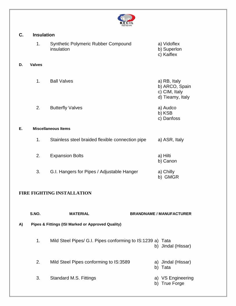
C. Insulation
1. Synthetic Polymeric Rubber Compound a) Vidoflex insulation b) Superlon c) Kaiflex
D. Valves
1. Ball Valves a) RB, Italy b) ARCO, Spain c) CIM, Italy d) Tieamy, Italy 2. Butterfly Valves a) Audco
b) KSB c) Danfoss
E. Miscellaneous Items
1. Stainless steel braided flexible connection pipe a) ASR, Italy 2. Expansion Bolts a) Hilti b) Canon 3. G.I. Hangers for Pipes / Adjustable Hanger a) Chilly b) GMGR
FIRE FIGHTING INSTALLATION
S.NO. MATERIAL BRANDNAME / MANUFACTURER
A) Pipes & Fittings (ISI Marked or Approved Quality)
1. Mild Steel Pipes/ G.I. Pipes conforming to IS:1239 a) Tata b) Jindal (Hissar)
2. Mild Steel Pipes conforming to IS:3589 a) Jindal (Hissar) b) Tata 3. Standard M.S. Fittings a) VS Engineering b) True Forge
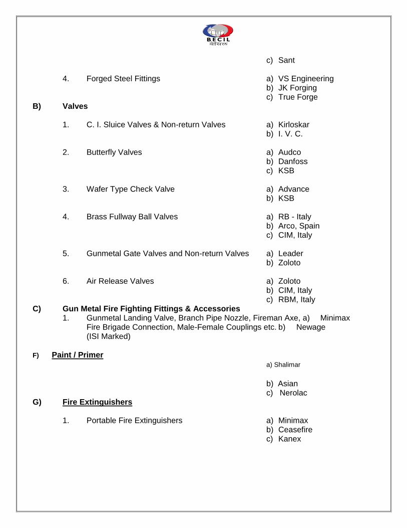
c) Sant 4. Forged Steel Fittings a) VS Engineering b) JK Forging c) True Forge
B) Valves 1. C. I. Sluice Valves & Non-return Valves a) Kirloskar b) I. V. C. 2. Butterfly Valves a) Audco b) Danfoss c) KSB 3. Wafer Type Check Valve a) Advance b) KSB 4. Brass Fullway Ball Valves a) RB - Italy b) Arco, Spain c) CIM, Italy 5. Gunmetal Gate Valves and Non-return Valves a) Leader b) Zoloto 6. Air Release Valves a) Zoloto b) CIM, Italy c) RBM, Italy
C) Gun Metal Fire Fighting Fittings & Accessories 1. Gunmetal Landing Valve, Branch Pipe Nozzle, Fireman Axe, a) Minimax Fire Brigade Connection, Male-Female Couplings etc. b) Newage (ISI Marked)
F) Paint / Primer a) Shalimar
b) Asian c) Nerolac G) Fire Extinguishers
1. Portable Fire Extinguishers a) Minimax b) Ceasefire c) Kanex
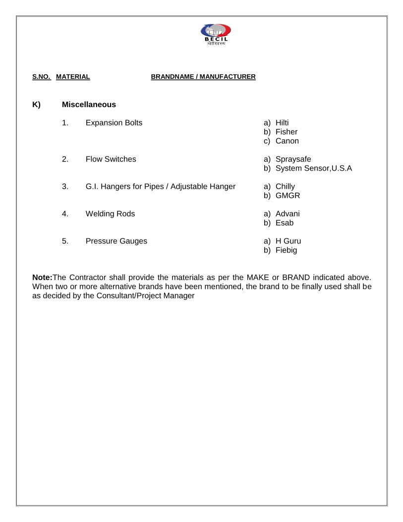
S.NO. MATERIAL BRANDNAME / MANUFACTURER
K) Miscellaneous
1. Expansion Bolts a) Hilti b) Fisher c) Canon 2. Flow Switches a) Spraysafe b) System Sensor,U.S.A 3. G.I. Hangers for Pipes / Adjustable Hanger a) Chilly b) GMGR 4. Welding Rods a) Advani b) Esab 5. Pressure Gauges a) H Guru b) Fiebig
Note:The Contractor shall provide the materials as per the MAKE or BRAND indicated above. When two or more alternative brands have been mentioned, the brand to be finally used shall be as decided by the Consultant/Project Manager
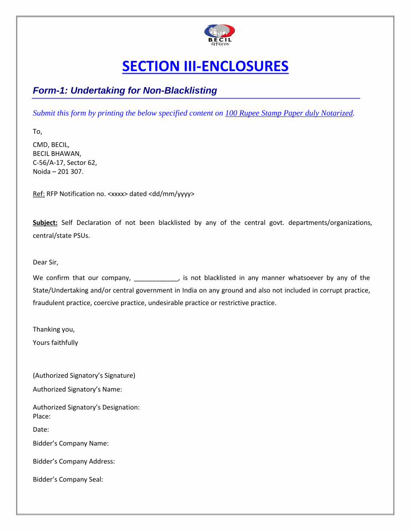
SECTION III-ENCLOSURES
Form-1: Undertaking for Non-Blacklisting
Submit this form by printing the below specified content on 100 Rupee Stamp Paper duly Notarized.
To, CMD, BECIL, BECIL BHAWAN, C-56/A-17, Sector 62, Noida – 201 307. Ref: RFP Notification no. <xxxx> dated <dd/mm/yyyy>
Subject: Self Declaration of not been blacklisted by any of the central govt. departments/organizations,
central/state PSUs.
Dear Sir, We confirm that our company, ____________, is not blacklisted in any manner whatsoever by any of the
State/Undertaking and/or central government in India on any ground and also not included in corrupt practice,
fraudulent practice, coercive practice, undesirable practice or restrictive practice.
Thanking you, Yours faithfully (Authorized Signatory’s Signature) Authorized Signatory’s Name: Authorized Signatory’s Designation: Place: Date: Bidder’s Company Name: Bidder’s Company Address: Bidder’s Company Seal:
Form-2: Total Responsibility Undertaking
Submit this form by printing the below specified content in your company letter head.
To, CMD, BECIL, BECIL BHAWAN, C-56/A-17, Sector 62, Noida – 201 307. Ref: RFP Notification no. <xxxx> dated <dd/mm/yyyy>
Sub: Self certificate regarding Total Responsibility Dear Sir,
This is to certify that we undertake total responsibility for the successful and defect free operation of the Project, as per
the requirements of the RFP for Civil & Interior/ Electrical/ HVAC & Plumbing Works for WDRA on 4th floor at
NCUI 3, Siri Institutional area, August Kranti Marg, Hauz Khas, New Delhi-16.
Thanking you, Yours faithfully (Authorized Signatory’s Signature) Authorized Signatory’s Name: Authorized Signatory’s Designation: Place: Date: Bidder’s Company Seal:
B. DRAWINGS (LAYOUT)
The respective drawings and layouts are available separately in CDs, which can be collected from BECIL CorporateOffice: BECIL BHAWAN, C-56-A/17, Sector-62, Noida-201 301
C. CHECK LIST
Please ensure that following documents have been enclosed alongwith the bid proposal
Inspect the site at WDRA on 4th floor at NCUI 3, Siri Institutional area, August Kranti Marg, Hauz Khas, New
Delhi-16.
1. Go through the tender documents very carefully and thoroughly.
2. Prepare separate technical and commercial bids.
3. Ensure submission of required documents and details alongwith technical bid. The documents to be enclosed
are:-
i) Proof of payment for fee of Rs. 20,000/- for purchase of tender document in the form of cash receipt or bank
draft for tender documents downloaded from site.
ii) Bank demand draft for Rs. 4, 00,000 /- towards earnest money deposit (EMD).
iii) Activity wise work schedule.
iv) Separate list of item recommended by bidders, which in the opinion of the bidder have been left out.
v) Copy of the registration certificate under Indian Company Act.
vi) Copies of the annual report and balance sheet in respect of last three financial years.
vii) Copy of the tender document duly signed and stamped by the bidder in support of having read, understood
and complied with the requirements of the tender document.
viii) Details of similar works executed alongwith approximate value of the projects in chronological order.
ix) Any other details and information of relevance in support of past experiences of the bidder.
x) Detailed bill of material duly filled in giving the offered material / equipment etc strictly as per the bill of
material included in the tender document.
4. BOM must be strictly quoted as per serial No./Heading/Subheading given in RFP
5. Duly signed and stamped compliance statement itemwise with respect to technical specifications highlighting
deviation, if any.
6. No cost details are to be included in the technical bid under any circumstances. The signed and stamped copies
of the technical bid containing requisite documents are to be sealed in separate envelope and marked
appropriately.
7. The commercial bid shall contain exactly similar offered bill of material included in the technical bid but with
full details on the rates, total cost. Only one copy of commercial bid duly signed and stamped is to be sealed
in a separate envelope and marked accordingly.
Both technical & commercial bids in respective sealed envelopes are to be further sealed in an envelope and
marked “BIDforCivil & Interior/ Electrical/ HVAC & Plumbing for WDRA on 4th floor at NCUI 3, Siri
Institutional area, August Kranti Marg, Hauz Khas, New Delhi-16”
8. The tender has to be addressed to
The Chairman & Managing Director
Broadcast Engineering Consultants India Ltd,
C-56 A/17, Sector -62, Noida 201 307
Tel: 0120-4177850
Fax: 0120-4177879
and the delivery of the same must be ensured at this officeon or before 12:00 hours on12th August 2016.