Embed Size (px)
Citation preview
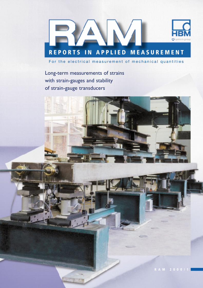
Long-term measurements of strainswith strain-gauges and stability of strain-gauge transducers
R E P O R T S I N A P P L I E D M E A S U R E M E N TF o r t h e e l e c t r i c a l m e a s u r e m e n t o f m e c h a n i c a l q u a n t i t i e s
R A M 2 0 0 0 / 1
2
RAM 2000/1
Results from experiments aiming at the evaluation of the long-term stability (at ambient temperature and in laboratory condi-tions) under constant sustained loading of strain-gauges and strain-gauge transducers are reported. A preliminary series ofexperiments involved the loading for more than 1 year of two 1 kN transducers, one at 100 % of its nominal force (2 mV/V)and the other at 50 % of its nominal force (1 mV/V).Then followed a detailed investigation of the influence of the strain-gaugetype, length, bonding and sign of strain on the long-term strain measurement. Creep curves under load and creep recoverycurves after unloading are represented graphically. A large variability in long-term stability, ranging from less than 0.2% to morethan 1%, is observed.
Prof. Dr. Ir. Bernard Espion, Prof.Dr.Ir. Pierre HalleuxLaboratory for Testing Materials and Structures, Civil Engineering Department, University of Brussels
1 Introduction
Some years ago, the authors conducted a series of experiments
to investigate the nonlinear behaviour up to failure of statical-
ly indeterminate concrete slabs postensioned with unbonded
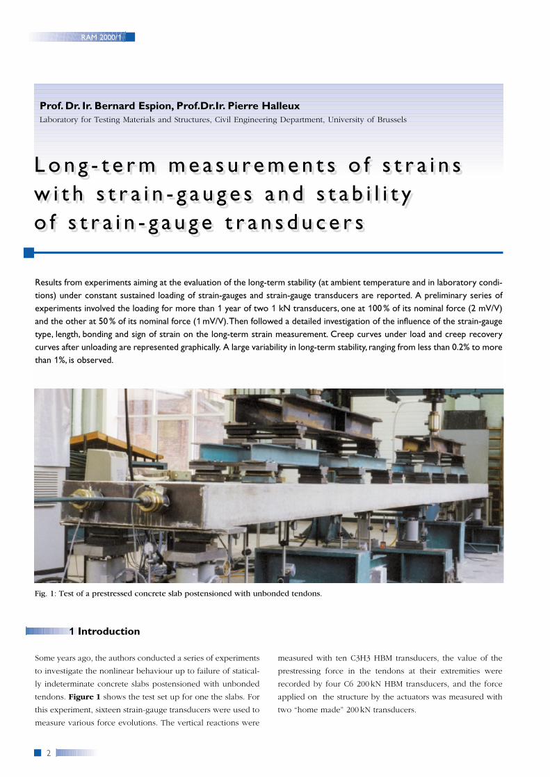
tendons. Figure 1 shows the test set up for one the slabs. For
this experiment, sixteen strain-gauge transducers were used to
measure various force evolutions. The vertical reactions were
measured with ten C3H3 HBM transducers, the value of the
prestressing force in the tendons at their extremities were
recorded by four C6 200 kN HBM transducers, and the force
applied on the structure by the actuators was measured with
two “home made” 200 kN transducers.
Fig. 1: Test of a prestressed concrete slab postensioned with unbonded tendons.
L o n g - t e r m m e a s u re m e n t s o f s t r a i n sw i t h s t r a i n - g a u g e s a n d s t a b i l i t yo f s t r a i n - g a u g e t r a n s d u c e r s
L o n g - t e r m m e a s u re m e n t s o f s t r a i n sw i t h s t r a i n - g a u g e s a n d s t a b i l i t y o f s t r a i n - g a u g e t r a n s d u c e r s
3
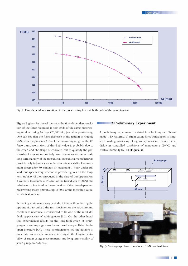
Figure 2 gives for one of the slabs the time-dependent evolu-
tion of the force recorded at both ends of the same prestress-
ing tendon during 14 days (20,000min) just after prestressing.
One can see that the force decrease in the tendon is roughly
5 kN, which represents 2.5% of the measuring range of the C6
force transducers. Most of this 5 kN value is probably due to
the creep and shrinkage of concrete, but to quantify the pre-
stressing losses more precisely, we have to know the intrinsic
long-term stability of the transducer. Transducer manufacturers
provide only information on the short-time stability like maxi-
mum creep after 30 minutes or maximum 1 hour under full
load, but appear very reticent to provide figures on the long-
term stability of their products. In the case of our application,
if we have to assume a 1 % drift of the transducer (= 2 kN), the
relative error involved in the estimation of the time-dependent
prestressing losses amounts up to 40% of the measured value,
which is significant.
Recording strains over long periods of time without having the
opportunity to unload the test specimen or the structure and
check zero reference is considered to be one of the most dif-
ficult applications of strain-gauges [1,2]. On the other hand,
few experimental results on the long-term creep of strain-
gauges or strain-gauge transducers have been published in the
open literature [3,4]. These considerations led the authors to
undertake some experiments to investigate the long-term sta-
bility of strain-gauge measurements and long-term stability of
strain-gauge transducers.
2 Preliminary Experiment
A preliminary experiment consisted in submitting two “home
made” 1 kN (at 2mV/V) strain-gauge force transducers to long-
term loading consisting of rigorously constant masses (steel
disks) in controlled conditions of temperature (20 °C) and
relative humidity (60%) (Figure 3).
RAM 2000/1
Fig. 2: Time-dependent evolution of the prestressing force at both ends of the same tendon
Fig. 3: Strain-gauge force transducer, 1 kN nominal force
100 mm
24 m
m20
Strain-gauges
132
131
130
129
128
127
126
125
124
123
Passive end
Active end
F (kN)
∆t (min)1 10 100 1000 10000 100000
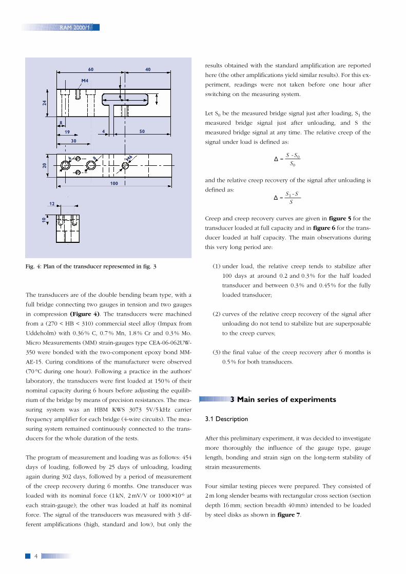
The transducers are of the double bending beam type, with a
full bridge connecting two gauges in tension and two gauges
in compression (Figure 4). The transducers were machined
from a (270 < HB < 310) commercial steel alloy (Impax from
Uddeholm) with 0.36% C, 0.7% Mn, 1.8% Cr and 0.3% Mo.
Micro Measurements (MM) strain-gauges type CEA-06-062UW-
350 were bonded with the two-component epoxy bond MM-
AE-15. Curing conditions of the manufacturer were observed
(70 °C during one hour). Following a practice in the authors'
laboratory, the transducers were first loaded at 150% of their
nominal capacity during 6 hours before adjusting the equilib-
rium of the bridge by means of precision resistances. The mea-
suring system was an HBM KWS 3073 5V/5 kHz carrier
frequency amplifier for each bridge (4-wire circuits). The mea-
suring system remained continuously connected to the trans-
ducers for the whole duration of the tests.
The program of measurement and loading was as follows: 454
days of loading, followed by 25 days of unloading, loading
again during 302 days, followed by a period of measurement
of the creep recovery during 6 months. One transducer was
loaded with its nominal force (1 kN, 2mV/V or 1000 ×10-6 at
each strain-gauge); the other was loaded at half its nominal
force. The signal of the transducers was measured with 3 dif-
ferent amplifications (high, standard and low), but only the
results obtained with the standard amplification are reported
here (the other amplifications yield similar results). For this ex-
periment, readings were not taken before one hour after
switching on the measuring system.
Let S0 be the measured bridge signal just after loading, S1 the
measured bridge signal just after unloading, and S the
measured bridge signal at any time. The relative creep of the
signal under load is defined as:
and the relative creep recovery of the signal after unloading is
defined as:
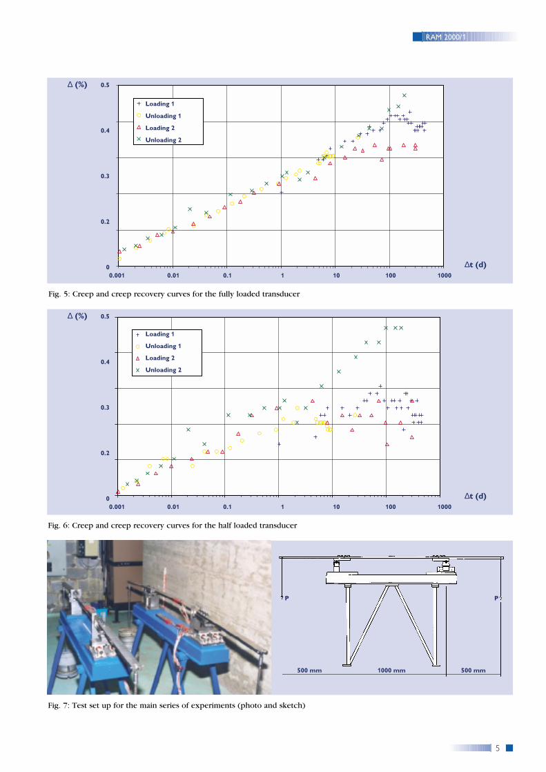
Creep and creep recovery curves are given in figure 5 for the
transducer loaded at full capacity and in figure 6 for the trans-
ducer loaded at half capacity. The main observations during
this very long period are:
(1) under load, the relative creep tends to stabilize after
100 days at around 0.2 and 0.3 % for the half loaded
transducer and between 0.3% and 0.45 % for the fully
loaded transducer;
(2) curves of the relative creep recovery of the signal after
unloading do not tend to stabilize but are superposable
to the creep curves;
(3) the final value of the creep recovery after 6 months is
0.5% for both transducers.
3 Main series of experiments
3.1 Description
After this preliminary experiment, it was decided to investigate
more thoroughly the influence of the gauge type, gauge
length, bonding and strain sign on the long-term stability of
strain measurements.
Four similar testing pieces were prepared. They consisted of
2m long slender beams with rectangular cross section (section
depth 16mm; section breadth 40mm) intended to be loaded
by steel disks as shown in figure 7.
S1 -S∆ =
S
S -S0∆ = S0
4
RAM 2000/1
60
12
M4
40
504
8
19
30
2420
100
10
M686
Fig. 4: Plan of the transducer represented in fig. 3
1000 mm500 mm 500 mm
P P
5
RAM 2000/1
Fig. 5: Creep and creep recovery curves for the fully loaded transducer
Fig. 6: Creep and creep recovery curves for the half loaded transducer
Fig. 7: Test set up for the main series of experiments (photo and sketch)
0.001 0.01 0.1 1 10 100 1000
0.5
0.4
0.3
0.2
0
Loading 1
Unloading 1
Loading 2
Unloading 2
∆ (%)
∆t (d)
0.001 0.01 0.1 1 10 100 1000
0.5
0.4
0.3
0.2
0
Loading 1
Unloading 1
Loading 2
Unloading 2
∆ (%)
∆t (d)
The steel of the testing pieces is a commercial steel alloy (Thy-
roplast 2311 from Thyssen) containing 0.4% C, 1.9% Cr, 1.5%
Mn and 0.2% Mo. It was sold pre-treated (280 < HB < 325) and
pre-finished from the manufacturer requiring no other machin-
ing than length adjusting and hole drilling for the connections.
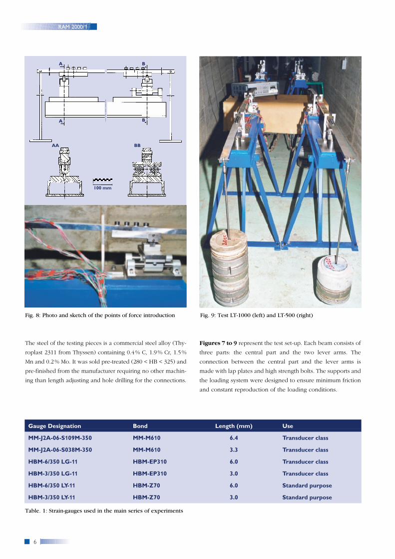
Figures 7 to 9 represent the test set-up. Each beam consists of
three parts: the central part and the two lever arms. The
connection between the central part and the lever arms is
made with lap plates and high strength bolts. The supports and
the loading system were designed to ensure minimum friction
and constant reproduction of the loading conditions.
6
RAM 2000/1
Fig. 9: Test LT-1000 (left) and LT-500 (right)
Gauge Designation Bond Length (mm) Use
MM-J2A-06-S109M-350 MM-M610 6.4 Transducer class
MM-J2A-06-S038M-350 MM-M610 3.3 Transducer class
HBM-6/350 LG-11 HBM-EP310 6.0 Transducer class
HBM-3/350 LG-11 HBM-EP310 3.0 Transducer class
HBM-6/350 LY-11 HBM-Z70 6.0 Standard purpose
HBM-3/350 LY-11 HBM-Z70 3.0 Standard purpose
Table. 1: Strain-gauges used in the main series of experiments
100 mm
BA
AA BB
A B
Fig. 8: Photo and sketch of the points of force introduction
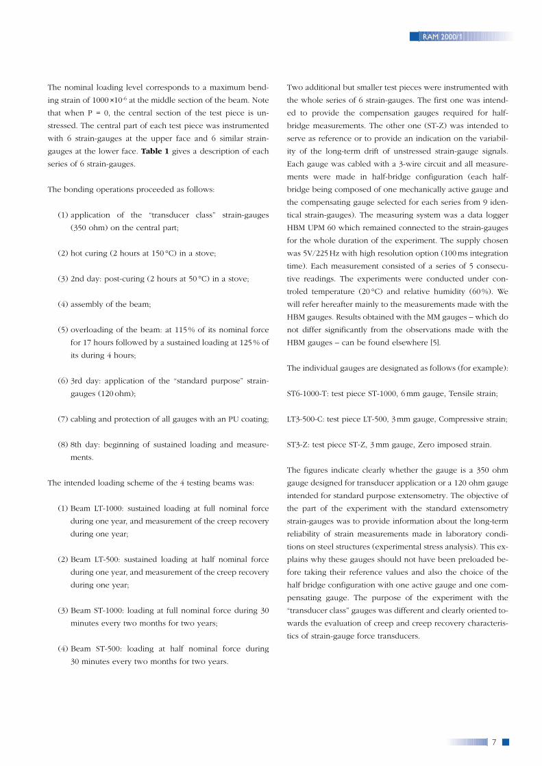
The nominal loading level corresponds to a maximum bend-
ing strain of 1000 ×10-6 at the middle section of the beam. Note
that when P = 0, the central section of the test piece is un-
stressed. The central part of each test piece was instrumented
with 6 strain-gauges at the upper face and 6 similar strain-
gauges at the lower face. Table 1 gives a description of each
series of 6 strain-gauges.
The bonding operations proceeded as follows:
(1) application of the “transducer class” strain-gauges
(350 ohm) on the central part;
(2) hot curing (2 hours at 150 °C) in a stove;
(3) 2nd day: post-curing (2 hours at 50 °C) in a stove;
(4) assembly of the beam;
(5) overloading of the beam: at 115% of its nominal force
for 17 hours followed by a sustained loading at 125% of
its during 4 hours;
(6) 3rd day: application of the “standard purpose” strain-
gauges (120 ohm);
(7) cabling and protection of all gauges with an PU coating;
(8) 8th day: beginning of sustained loading and measure-
ments.
The intended loading scheme of the 4 testing beams was:
(1) Beam LT-1000: sustained loading at full nominal force
during one year, and measurement of the creep recovery
during one year;
(2) Beam LT-500: sustained loading at half nominal force
during one year, and measurement of the creep recovery
during one year;
(3) Beam ST-1000: loading at full nominal force during 30
minutes every two months for two years;
(4) Beam ST-500: loading at half nominal force during
30 minutes every two months for two years.
Two additional but smaller test pieces were instrumented with
the whole series of 6 strain-gauges. The first one was intend-
ed to provide the compensation gauges required for half-
bridge measurements. The other one (ST-Z) was intended to
serve as reference or to provide an indication on the variabil-
ity of the long-term drift of unstressed strain-gauge signals.
Each gauge was cabled with a 3-wire circuit and all measure-
ments were made in half-bridge configuration (each half-
bridge being composed of one mechanically active gauge and
the compensating gauge selected for each series from 9 iden-
tical strain-gauges). The measuring system was a data logger
HBM UPM 60 which remained connected to the strain-gauges
for the whole duration of the experiment. The supply chosen
was 5V/225Hz with high resolution option (100ms integration
time). Each measurement consisted of a series of 5 consecu-
tive readings. The experiments were conducted under con-
troled temperature (20 °C) and relative humidity (60%). We
will refer hereafter mainly to the measurements made with the
HBM gauges. Results obtained with the MM gauges – which do
not differ significantly from the observations made with the
HBM gauges – can be found elsewhere [5].
The individual gauges are designated as follows (for example):
ST6-1000-T: test piece ST-1000, 6mm gauge, Tensile strain;
LT3-500-C: test piece LT-500, 3mm gauge, Compressive strain;
ST3-Z: test piece ST-Z, 3mm gauge, Zero imposed strain.
The figures indicate clearly whether the gauge is a 350 ohm
gauge designed for transducer application or a 120 ohm gauge
intended for standard purpose extensometry. The objective of
the part of the experiment with the standard extensometry
strain-gauges was to provide information about the long-term
reliability of strain measurements made in laboratory condi-
tions on steel structures (experimental stress analysis). This ex-
plains why these gauges should not have been preloaded be-
fore taking their reference values and also the choice of the
half bridge configuration with one active gauge and one com-
pensating gauge. The purpose of the experiment with the
“transducer class” gauges was different and clearly oriented to-
wards the evaluation of creep and creep recovery characteris-
tics of strain-gauge force transducers.
7
RAM 2000/1
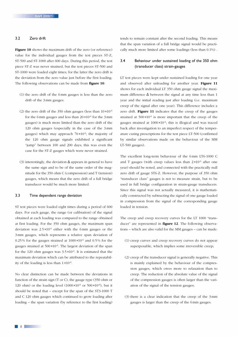
3.2 Zero drift
Figure 10 shows the maximum drift of the zero (or reference)
value for the individual gauges from the test pieces ST-Z,
ST-500 and ST-1000 after 600 days. During this period, the test
piece ST-Z was never strained, but the test pieces ST-500 and
ST-1000 were loaded eight times; for the latter the zero drift is
the deviation from the zero value just before the first loading.
The following observations can be made from figure 10:
(1) the zero drift of the 6mm gauges is less than the zero
drift of the 3 mm gauges.
(2) the zero drift of the 350 ohm gauges (less than 10 ×10-6
for the 6mm gauges and less than 20 ×10-6 for the 3mm
gauges) is much more limited than the zero drift of the
120 ohm gauges (especially in the case of the 3mm
gauges) which may approach 70 ×10-6; the majority of
the 120 ohm gauge signals exhibited a significant
“jump” between 100 and 200 days; this was even the
case for the ST-Z gauges which were never strained.
(3) interestingly, the deviation ∆ appears in general to have
the same sign and to be of the same order of the mag-
nitude for the 350 ohm C (compression) and T (tension)
gauges, which means that the zero drift of a full bridge
transducer would be much more limited.
3.3 Time dependent range deviation
ST test pieces were loaded eight times during a period of 600
days. For each gauge, the range (or calibration) of the signal
obtained at each loading was compared to the range obtained
at first loading. For the 350 ohm gauges, the maximum span
deviation was 2.5 ×10⁻⁶ either with the 6mm gauges or the
3mm gauges, which represents a relative span deviation of
0.25 % for the gauges strained at 1000 ×10-6 and 0.5% for the
gauges strained at 500 ×10-6. The largest deviation of the span
for the 120 ohm gauges was 3.5 ×10⁻⁶. It is estimated that the
maximum deviation which can be attributed to the repeatabil-
ity of the loading is less than 1 ×10⁻⁶.
No clear distinction can be made between the deviations in
function of the strain sign (T or C), the gauge type (350 ohm or
120 ohm) or the loading level (1000 ×10-6 or 500 ×10-6), but it
should be noted that – except for the span of the ST3-1000 T
and C 120 ohm gauges which continued to grow loading after
loading – the span variation (by reference to the first loading)
tends to remain constant after the second loading. This means
that the span variation of a full bridge signal would be practi-
cally much more limited after some loadings (less than 0.1%) .
3.4 Behaviour under sustained loading of the 350 ohm(transducer class) strain-gauges
LT test pieces were kept under sustained loading for one year
and observed after unloading for another year. Figure 11
shows for each individual LT 350 ohm gauge signal the maxi-
mum difference ∆ between the signal at any time less than 1
year and the initial reading just after loading (i.e. maximum
creep of the signal after one year). This difference includes a
zero drift. Figure 11 indicates that the creep of the gauges
strained at 500 ×10-6 is more important that the creep of the
gauges strained at 1000 ×10-6; this is illogical and was traced
back after investigation to an imperfect respect of the temper-
ature curing prescriptions for the test piece LT-500 (confirmed
by similar observations made on the behaviour of the MM
LT-500 gauges).
The excellent long-term behaviour of the 6mm LT6-1000 C
and T gauges (with creep values less than 2 ×10⁻⁶ after one
year) should be noted, and connected with the practically null
zero drift of gauge ST6-Z. However, the purpose of 350 ohm
“transducer class” gauges is not to measure strain, but to be
used in full bridge configuration in strain-gauge transducers.
Since this signal was not actually measured, it is mathemati-
cally constructed by subtracting the signal of one gauge loaded
in compression from the signal of the corresponding gauge
loaded in tension.
The creep and creep recovery curves for the LT 1000 “trans-
ducer” are represented in figure 12. The following observa-
tions – which are also valid for the MM gauges – can be made:
(1) creep curves and creep recovery curves do not appear
superposable, which implies some irreversible creep;
(2) creep of the transducer signal is generally negative. This
is mainly explained by the behaviour of the compres-
sion gauges, which owes more to relaxation than to
creep. The reduction of the absolute value of the signal
of the compression gauges is often larger than the vari-
ation of the signal of the tension gauges;
(3) there is a clear indication that the creep of the 3mm
gauges is larger than the creep of the 6 mm gauges.
8
RAM 2000/1
9
RAM 2000/1
Fig. 12: Creep and recovery curves for the LT-1000 “transducer” with HBM 6 mm and 3 mm strain-gauges
Fig. 10: Maximum drift of the reference value after 600 days
Fig. 11: Maximum creep of the LT/350 ohm gauge signals after one year
-20 -10 0 10 20 30 40 50 60 70 80
-20 -10 0 10 20 30
0.0001 0.001 0.01 0.1 1 10 100 1000
ST6-1000-T
ST6-1000-C
ST6-500-T
ST6-500-C
ST6-Z
ST3-1000-T
ST3-1000-C
ST3-500-T
ST3-500-C
ST3-Z
Gauge
LT6-1000-T
LT6-1000-C
LT6-500-T
LT6-500-C
LT3-1000-T
LT3-1000-C
LT3-500-T
LT3-500-C
Gauge
0.10
0.00
-0.10
-0.20
-0.30
-0.40
-0.50
-0.60
-0.70
-0.80
∆(%)
∆(µm)
∆(µm)
∆t(d)
120 ohm
350 ohm
350 ohm
Creep 6 mm
Creep 3 mm
Recovery 6 mm
Recovery 3 mm
10
RAM 2000/1
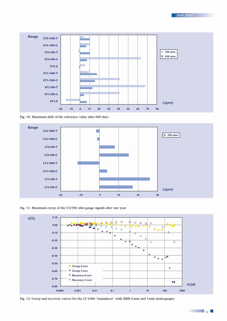
3.5 Behaviour under sustained loading of the 120 ohm(standard purpose) strain-gauges
Figure 13 shows for each individual LT 120 ohm gauge signal
the maximum difference ∆ between the signal at one year and
the initial reading just after loading. The comparison with -
figure 11 indicates that the creep of the “standard purpose”
gauges is much larger than the creep of the “transducer class”
gauge. Note that, here, the results with the LT-500 test piece
are not affected by curing (120 ohm gauges were bonded with
a HBM Z70 cold curing bond) and can be kept for the com-
parison with the measurements from the LT-1000 test piece.
Besides figure 13, the following additional conclusions re-
garding the behaviour and the use of the ordinary strain-
gauges can be drawn from the time-dependent evolution of
the signals:
(1) their creep up to 100 days is continuous, but nearly all
creep curves exhibited a significant discontinuity be-
tween 100 days and one year; it has been mentioned be-
fore that a discontinuity also appeared in the record of
the value of the measured strain signal for the 120 ohm
gauges from the ST-1000, ST-500 and ST-Z test pieces;
(2) up to 100 days (before the discontinuity), their creep
remains compatible with stress analysis applications, the
largest value being 4% of the initial value;
(3) up to 100 days, the cross-behaviour of all these gauges
remains coherent:
• the relative creep of the 1000 ×10-6 gauges is somewhat
more important than the relative creep of the 500 ×10-6
gauges;
• the creep of the signal is always negative, i.e. the absolute
value of the signal of the compression gauges decreases
and the signal of the tension gauges decreases as well;
• the creep is more pronounced in compression than in ten-
sion;
• the creep of the signal of the 6mm gauges is less than the
creep of the signal of the 3mm gauges, which is in agree-
ment with data published in the literature [6].
4 Conclusions
The aim of the experiments was to investigate the long-term
stability (as against an initial reference value) of strain-gauge
signals with strains and of strain-gauge transducers in associa-
tion with their measuring systems at ambient temperature.
Although the repeatability of strain variation measurements
(i.e. with zero adjustment) with standard purpose strain-
gauges is very good over a long period of time, this kind of
strain-gauges should not be used for long-term measurements
if high precision is required, because large zero drift or creep
are observed some time after loading.
Figure 13 : Maximum creep of the LT/120 ohm gauge signals after one year
-80 -60 -40 -20 0 20 40 60 80
LT6-1000-T
LT6-1000-C
LT6-500-T
LT6-500-C
LT3-1000-T
LT3-1000-C
LT3-500-T
LT3-500-C
Gauge
∆(µs)
120 ohm
11
RAM 2000/1
The ST experiments have confirmed what we know by expe-
rience in our laboratory where we frequently still use “home
made” transducers which were constructed more than 30 years
ago, i. e. that the calibration of strain-gauge transducers which
are only used periodically and which can be zero referenced
remains very accurate over long period of times.
The design of transducers for long-term (more than one year)
sustained loading without having the possibility of zero refer-
encing is another problem and remains largely empirical. Our
experiments with home made transducers revealed a rather
wide spectrum of long-term relative creep ranging from less
than 0.2% up to more than 1%. The influence of all parameters
is not yet fully understood: some transducers exhibited
reversibility, and others did not; some transducers exhibited
positive creep and others negative creep; most transducers did
not exhibit an asymptotic creep value. A clear reduction of
creep is obtained by using 6mm gauges rather than 3 mm
gauges and by strictly following the curing conditions imposed
by the bond manufacturer.
Although the HBM measuring systems (KWS and UPM 60) per-
formed excellently during the experiments, it should be men-
tioned that measuring relative creep values less than 0.1% for
very long times is generally hampered by the resolution of the
measuring system and its intrinsic stability and the reliability of
the loading system, since it implies to measure and read less
than 1µm at 1000 ×10-6 or less than 0.5 µm at 500 ×10-6 !
References
[1] J.W. Dally,W.F. Riley, J.S. Sirkis, Strain gages, in Handbook onExperimental Stress Analysis (ed. by A.S. Kobayashi), 2nd ed, SEM,1993, pp.57-58.
[2] G.F. Chalmers, Materials, construction, performance and characteristics,in Strain Gauge Technology (ed. by A.L.Window and G.S. Holisters),Applied Science Publishers, London, 1982, p.28.
[3] H.S. Freynik, G.R. Dittbenner, Strain gage stability measurements foryears at 75°C in air, Experimental Mechanics, 16 (4),April 1976,pp.155-160.
[4] H. Paul,Anmerkungen und Testergebnisse zur Langzeitstabilität vonDehnungsmeßstreifen und DMS-Aufnehmern,VDI Berichte, 731, 1989,pp.419 - 430.
[5] B. Espion, P. Halleux, Some experimental results on long-term stability ofstrain-gauge load cells, Proceedings of the Int. Conference on MaterialEngineering, Lecce, 1996, pp.729-736.0
[6] K. Hoffmann,An Introduction to Measurements using Strain Gages,HBM GmbH, Darmstadt, 1989.
[7] J.Avril (ed), Encyclopédie d'Analyse des Contraintes, Micromesures,Paris, 1984.

HOTTINGER BALDWIN
MESSTECHNIK
HBM Mess- und Systemtechnik GmbHIm Tiefen See 45D-64293 Darmstadt
Tel. +49 / 61 51 / 803 - 0Fax +49 / 61 51 / 89 48 96www.hbm.de
Contributions are welcome and if printed,
a fee will be paid
Reply to - Fax No.: +49 / 6151 / 803-396
(HBM, Editorial Office)
oder Fax Nr: +43 / 316 / 873 73 70
Prof. Dr. Peter Grünbaum
Name
Company / Dept.
Street
Town / Postcode
Telephone
Fax
� I am interested in having an article published in
RAM and would ask you to kindly contact me.
Imprint:
Publisher:
HBM Mess- und Systemtechnik GmbH
Im Tiefen See 45 · D-64293 Darmstadt
Germany
www.hbm.de
Person responsible for content: Prof. Dipl.-Ing. Dr.
techn. Peter Grünbaum, Technical University of Graz
In case of questions on the RAM or the articles please
contact Prof. Dipl.-Ing. Dr. techn. Peter Grünbaum.
In case of questions on HBM products please contact
your HBM representative.
Copying is only permitted with the advance written
approval of the editorial office or the publisher.
Copying or reproduction in the form of photocopies,
microfilm or other means for commercial purposes is
not permitted.
All rights reserved: no liability can be accepted for the
procedures and circuits described and the names used
in respect of the infringement of patents or
trademarks of third parties.
Printing: 100% chlorine-free bleached paper has been
used to protect the environment.
Reports in Applied Measurement 2000/1
Issued: 3 times a year
Issue date: March 2000
ISSN 0930-7923