Embed Size (px)
Citation preview
MAINTENANCE OF FLOATING CRAFTS
Submitted by
NAME : N.V.S.KALYAN ADMN. NO.: 2012JE1025
DEPARTMENT OF MECHANICAL ENGINNERING
INDIAN SCHOOL OF MINES, DHANBAD
Under the guidance of
B.VARADHA RAJULU M M GR.I, FLOATING CRAFTS SECTION VISAKHAPATNAM PORT TRUST

FLOATING CRAFTS CERTIFICATE
This is to Certify that the Training Report on MAINTENANCE
OF FLOATING CRAFTS submitted by
NAME : N.V.S.KALYAN ADMN. NO.: 2012JE1025
is a record of Bonafide work carried out by him, under the
guidance and supervision during the period of 30th JUNE
2014 to 13th JULY 2014.
J.LAL FOREMAN
FLOATING CRAFTS SECTION VISAKHAPATNAM PORT TRUST
B.JAGADESHWARA RAO MARINE ENGINEER HEAD OF FLOATING CRAFTS SECTION VISAKHAPATNAM PORT TRUST
B.VARADHA RAJULU
M M GR.I, FLOATING CRAFTS SECTION VISAKHAPATNAM PORT TRUST
CONTENTS
1. INTRODUCTION – VISAKHAPATNAM PORT
2. FLOATING CRAFTS SECTION
3. ENGINE
4. TWO STROKE DIESEL ENGINE
5. FOUR STROKE DIESEL ENGINE
6. DIESEL CYCLE
7. AIR STARTING SYSTEM OF DIESEL ENGINE
8. FUEL OIL SYSTEM OF DIESEL ENGINE
9. COOLING SYSTEM OF DIESEL ENGINE
10. LUBRICATION SYSTEM OF DIESEL ENGINE

INTRODUCTION
VISAKHAPATNAM PORT TRUST
VISAKHAPATNAM PORT is one of the 13 major ports in India and the only
major port of Andhra Pradesh. It is India’s second largest port by the
volume of cargo handling. It is located on the east coast of India and is
located midway between the Chennai and Kolkata Ports.
HISTORY
Although the need for building a port on the east coast to access Central
Provinces was felt by the British in the 19th century, the proposal of Col.
H. Cartwright Reid of British Admiralty for constructing a harbour at
Visakhapatnam was approved by the Government only after the First
World War. The Inner Harbour was built by the Bengal Nagpur Railway
between 1927 and 1933 to facilitate the export of manganese ore from

the Central Provinces. The Port built at a cost of ₹ 378 lakhs was
inaugurated by Lord Willingdon on 19 December 1933.
During the Second World War, the military significance of the port
increased. After India’s independence, the port witnessed growth under
the various Five Year Plans. Over time, the port has grown from one with
3 berths handling 1.3 lakh tonnes per annum to one with 24 berths and
annual traffic of 65 million tonnes. The port was notified as a major port
in 1964 under the Major Port Trusts Act, 1963. Under the Act, the
Visakhapatnam Port Trust is in charge of running the port.
LAYOUT OF THE PORT
Visakhapatnam Port has three harbours – the Outer Harbour, the Inner
Harbour and the Fishing Harbour. The Outer Harbour has 6 berths
capable of handling vessels with a draft up to 17 meters while the smaller
Inner Harbour has 18 berths that are Panamax compatible. The Dolphin’s
Nose Hill to the north of the entrance channel protects the harbour from
cyclones that strike the east coast.
HINTERLAND AND CARGO
The Hinterland of the Visakhapatnam Port extends to Telengana and
North Eastern Andhra Pradesh, Chhattisgarh, South Eastern Madhya
Pradesh, Southern Orissa and the Vidarbha region of Maharashtra.
Iron ore, Manganese ore, Steel products, General cargo, Coal and Crude
Oil are the main commodities handled at this port.
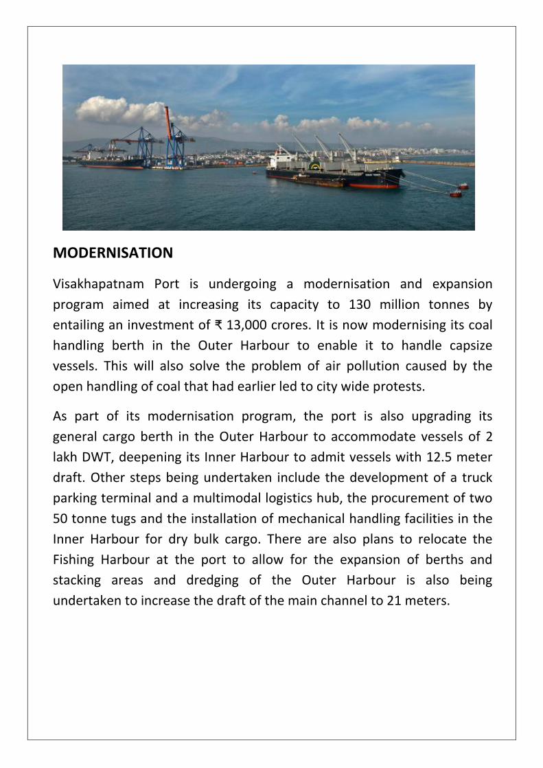
MODERNISATION
Visakhapatnam Port is undergoing a modernisation and expansion
program aimed at increasing its capacity to 130 million tonnes by
entailing an investment of ₹ 13,000 crores. It is now modernising its coal
handling berth in the Outer Harbour to enable it to handle capsize
vessels. This will also solve the problem of air pollution caused by the
open handling of coal that had earlier led to city wide protests.
As part of its modernisation program, the port is also upgrading its
general cargo berth in the Outer Harbour to accommodate vessels of 2
lakh DWT, deepening its Inner Harbour to admit vessels with 12.5 meter
draft. Other steps being undertaken include the development of a truck
parking terminal and a multimodal logistics hub, the procurement of two
50 tonne tugs and the installation of mechanical handling facilities in the
Inner Harbour for dry bulk cargo. There are also plans to relocate the
Fishing Harbour at the port to allow for the expansion of berths and
stacking areas and dredging of the Outer Harbour is also being
undertaken to increase the draft of the main channel to 21 meters.

FLOATING CRAFTS SECTION
Floating Crafts is one of the main sections of Visakhapatnam Port Trust.
Its role is to maintain the crafts ( ie., Tugs, Launches, Cranes etc. ) and
takes the vessels into channel to its destination. Due to zig-zag channel
and of its V-shape depth with less width, heavy vessels cannot pass
through the channel on its own, that is the reason they were taken by
Tugs. This channel is connected to industries like Hindustan Shipyard Ltd.,
Naval Dockyard etc and even to Port.
The following are the crafts under Floating Crafts Section –
o Tractor Tugs – Swatantra, M.V.Vajra, Mahatma, Sardar Patel, Jhansi
Rani, Col.H.Cart Wright Reid and A.W.Delima.
o Cranes – Bheema and Hanuman.
o Fire Float
o Launches – Maha Laxmi and Amba.
o Survey Launches – Nirmal
o Pilot Launches – Meghadri, Vizag Pilot and Sagar Pilot.
o Cleaning Launche – Jala Sudhak
o VIP Launche – M.S.Samba Murthy
o Dredgers – G.H.D.Sagar Durga and G.D.Newlark.

ENGINE
An Engine or Motor is a machine designed to convert energy into useful
mechanical motion. Heat engines, including Internal Combustion engines
and External Combustion engines burn fuel to create heat, which then
creates motion. Electric motors convert electrical energy into mechanical
motion, Pneumatic motors use compressed air and others – such as
Clockwork motors in Wind-up toys – use Elastic energy. In biological
systems, Molecular motors, like Myosins in muscles, use chemical energy
to create motion.
Heat Engine
Heat engine is a device which transforms the chemical energy of a fuel
into heat energy and utilizes this energy to perform useful work. Thus the
heat engines conert heat energy into mechanical energy. These are
classified as -
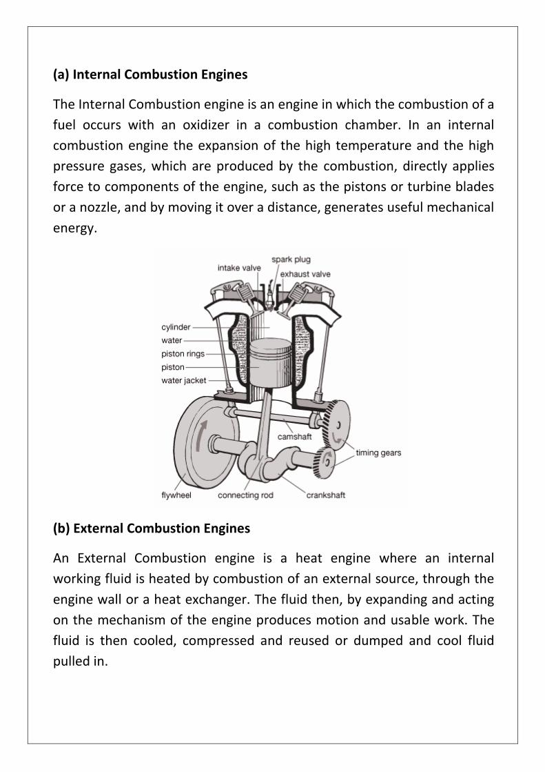
(a) Internal Combustion Engines
The Internal Combustion engine is an engine in which the combustion of a
fuel occurs with an oxidizer in a combustion chamber. In an internal
combustion engine the expansion of the high temperature and the high
pressure gases, which are produced by the combustion, directly applies
force to components of the engine, such as the pistons or turbine blades
or a nozzle, and by moving it over a distance, generates useful mechanical
energy.
(b) External Combustion Engines
An External Combustion engine is a heat engine where an internal
working fluid is heated by combustion of an external source, through the
engine wall or a heat exchanger. The fluid then, by expanding and acting
on the mechanism of the engine produces motion and usable work. The
fluid is then cooled, compressed and reused or dumped and cool fluid
pulled in.

Terminology of Internal Combustion Engine
o Top Dead Center ( TDC ) : A point at the top of cylinder where the
piston changes its direction of motion to downwards is called Top
Dead Center.
o Bottom Dead Center ( BDC ) : A point at the bottom of cylinder where
the piston changes its direction of motion to upwards is called Bottom
Dead Center.
o Stroke : The distance travelled by the piston from TDC to BDC or BDC
to TDC is called as Stroke.
o Cycle : The Cycle is a set of operations taking place in an engine in
regular order or a series of events which are repeated in a regular
order in the operation of an Engine.
o Valve Timing : The precise timing of opening and closing of the valves
is known as Valve Timing.
o Valve Overlap Period : The period during which both inlet and exhaust
valves remain open is known as Valve Overlap Period.
o Clearance Volume : The space between the piston and cylinder head
when the piston is at TDC is called as Clearance Volume or Combustion
Volume.
o Swept Volume : The volume swept by the piston from TDC to BDC or
from BDC to TDC is called as Swept Volume or Displacement Volume.
Basic Internal Combustion Engine parts
o Cylinder Head : It usually sits above the cylinders on top of the
cylinder block. It closes in the top of the cylinder, forming the
combustion chamber. In most of the engines, the head also provides
space for the passages that feed air and fuel to the cylinder, and that
allow the exhaust to escape. The head can also be a place to mount
the valves, spark plugs and fuel injectors.
o Cylinder Block : It is an integrated structure comprising the cylinder of
a reciprocating engine and often some or all of their associated

surrounding structures like coolant passages, intakes and exhaust
passages and ports and crank case.
o Crank Case : It is the housing for the crank shaft, cam shaft, timing
gear and etc., and has an oil passage for the circulation of lubricating
oil to the various parts of engine.

TWO STROKE DIESEL ENGINE
A Two Stroke Diesel Engine is a diesel engine that works in two strokes. A
diesel engine is an internal combustion engine which operates using the
Diesel cycle. All diesel engines use compression ignition, a process by
which fuel is injected after the air is compressed in the combustion
chamber causing the fuel to self ignite. By contrast, gasoline engines
utilize the Otto cycle, in which fuel and air are mixed before entering the
combustion chamber and then ignited by a spark plug.
Two Strokes
Two-stroke internal combustion engines are more simple mechanically
than four-stroke engines, but more complex in thermodynamic and
aerodynamic processes. In a two-stroke engine, the four ‘cycles’ of
internal combustion engine theory occur in one revolution, while in a
four-stroke engine it occurs in two complete revolutions. In a two-stroke
engine, more than one function occurs at any given time during the
engine’s operation.
First stroke : Intake begins when the piston is near the bottom dead
center. Air is admitted to the cylinder through ports in the cylinder wall (
there are no intake valves ). All two-stroke Diesel engines require artificial
aspiration to operate, and will either use a mechanically-driven blower or
a hybrid turbo-supercharger to charge the cylinder with air. In the early
phase of intake, the air charge is also used to force out any remaining
combustion gases from the preceding power stroke and this process is
known as Scavenging.
Second stroke : As the piston rises, the intake charge of air is compressed.
Near TDC, fuel is injected, resulting in combustion due to the extremely
high pressure and heat created by compression, which drives the piston
downward. As the piston moves downward in the cylinder it will reach a

point where the exhaust port is opened to expel the high-pressure
combustion gases.
In most GM and EMD engines, very few parameters are variable and all
the remaining ones are fixed. The scavenging ports are open from about
45 degrees before BDC to about 45 degrees after BDC and the fuel is
injected at 4 degrees before TDC. The remaining parameters have to do
with exhaust valve timing and these are set to effect maximum exhaust
scavenging and maximum intake charge air, and these two parameters
are not necessarily symmetrical about TDC. A single camshaft operates
the valves and the Unit injector, using three lobes: two for exhaust valves
and the third for the Unit injector.

FOUR STROKE DIESEL ENGINE
A Four Stroke Diesel Engine is a diesel engine that works in four strokes. A
diesel engine is an internal combustion engine which operates using the
Diesel cycle. All diesel engines use compression ignition, a process by
which fuel is injected after the air is compressed in the combustion
chamber causing the fuel to self ignite.
Four strokes
Four-stroke internal combustion engines are mechanically complex than
two-stroke engines, but more simpler in thermodynamic and
aerodynamic processes. In a four-stroke engine, the four ‘cycles’ of
internal combustion engine theory occur in two complete revolutions.
First stroke or Intake stroke : The crankshaft rotates clockwise and the
piston moves down the cylinder, then the inlet valve is opened and a
fresh charge of air is being drawn or pushed into the cylinder by the turbo
charger.
Second stroke or Compression stroke : The inlet valve closes and the
charge of air is compressed by the piston as it moves up the cylinder.
Because of compression the energy transfers into the air and the
temperature and pressure increases. By the time the piston approaches
the TDC the pressure is over 100 bars and temperature is over 500
degrees C.
Third stroke or Power stroke : Just before the piston reaches the TDC, the
fuel is injected into the cylinder by the fuel injector. The fuel is atomised
into tiny droplets which quickly ignites as the piston reaches the TDC. As
the fuel ignites, lot energy is produced as a result the piston is moved to
BDC.

Forth stroke and Exhaust stroke : The crank shaft rotates the piston
upwards and the exhaust valve opens, as a result the combusted gases
are expelled from the cylinder.

DIESEL CYCLE
The Diesel cycle is the thermodynamic cycle which approximates the
pressure and the volume of the combustion chamber of the diesel engine,
invented by Rudolph Diesel in 1897. It is assumed to have constant
pressure during the first part of the combustion phase. This is an idealised
mathematical model : real physical diesels do have an increase in
pressure during this period, but it is less pronounced than in Otto cycle.
The idealised Otto cycle of the gasoline engine approximates constant
volume during that phase, generating more of a spike in a p-V diagram.
Process 1-2 is an Isentropic compression of fluid
Process 2-3 is Reversible constant pressure heating
Process 3-4 is Isentropic expansion
Process 4-1 is Reversible constant volume cooling

AIR STARTING SYSTEM OF DIESEL ENGINE
An Air-start system is a power source used to provide the initial rotation
to start large diesel and gas turbine engines. Air-start system of Diesel
engines in of two kinds. They are –
Direct starting
Compared to gasoline engine, diesel engines have very high compression
ratios to provide for reliable and complete ignition of the fuel without
spark plugs. An electric starter powerful enough to turn a large diesel
engine would itself be so large as to be impractical, thus the need for an
alternating system. When starting the engine, compressed air is admitted
to which ever cylinder as a piston over the TDC, forcing it downward. As
the engine starts to turn, the air-start valve on the next cylinder in line
opens to continue the rotation. As this goes on, fuel is injected into the
cylinders, the engine is then under way and the air is cut off. To further
complicate matters, a large engine is usually blown over first with zero
fuel setting and the indicator cocks open, to prove that the engine is clear
of any water built up and that everything is free to turn. After successful
blown ahead and a blow astern, the indicator cocks are closed on all the
cylinders and then the engine can be started on the fuel. Significant
complexity is added to the engine by using the air-start system, asa
cylinder head must have an extra valve in each cylinder to admit the air in
for starting, plus the required control systems. This added complexity and
cost limits the use of air starters to very large and expensive reciprocating
engines.
Pneumatic Starter
Some gas turbine engines and diesel engines use a pneumatic self starter.
Compressed air released from the tank is used to spin the turbine and
through a set of reduction gears, engages the ring gear on the flywheel,

much like an electric starter. The engine once running, drives the
compressor to recharge the tank.
On large diesel generators found in large shore installations and
especially on ships, a pneumatic starting gear is used. The air motor is
normally powered by compressed air at pressures of 10 – 30 bar. The air
motor is made of a central drum about the size of a soup can with four or
more slots cut into it to allow for the vanes to be placed radially on the
drum to form chambers around the drum. The drum is offset inside a
round casting so that the inlet air for starting is admitted at the area
where the drum and vanes form a small chamber compared to the
others. The compressed air can only expand by rotating the drum which
allows the small chamber to become larger and puts another one of the
chambers in the air inlet. The air motor spins much too fast to be used
directly on the flywheel of the engine; instead a large gearing reduction,
such as planetary gearing is used to lower the output speed. A Bendix
gear is used to engage the flywheel.

FUEL OIL SYSTEM OF DIESEL ENGINE
Marine diesel engines are designed to burn heavy residual fuel. This is
made up of residues after the lighter and more costly fuels and gases have
been taken out of the crude oil at the refinery. The graphic below
illustrates the process
The diagram below shows a fuel oil supply system for a large two stroke
cross head engine. However the setup is typical of any fuel systems for a
marine diesel engine operating on heavy residual fuel.
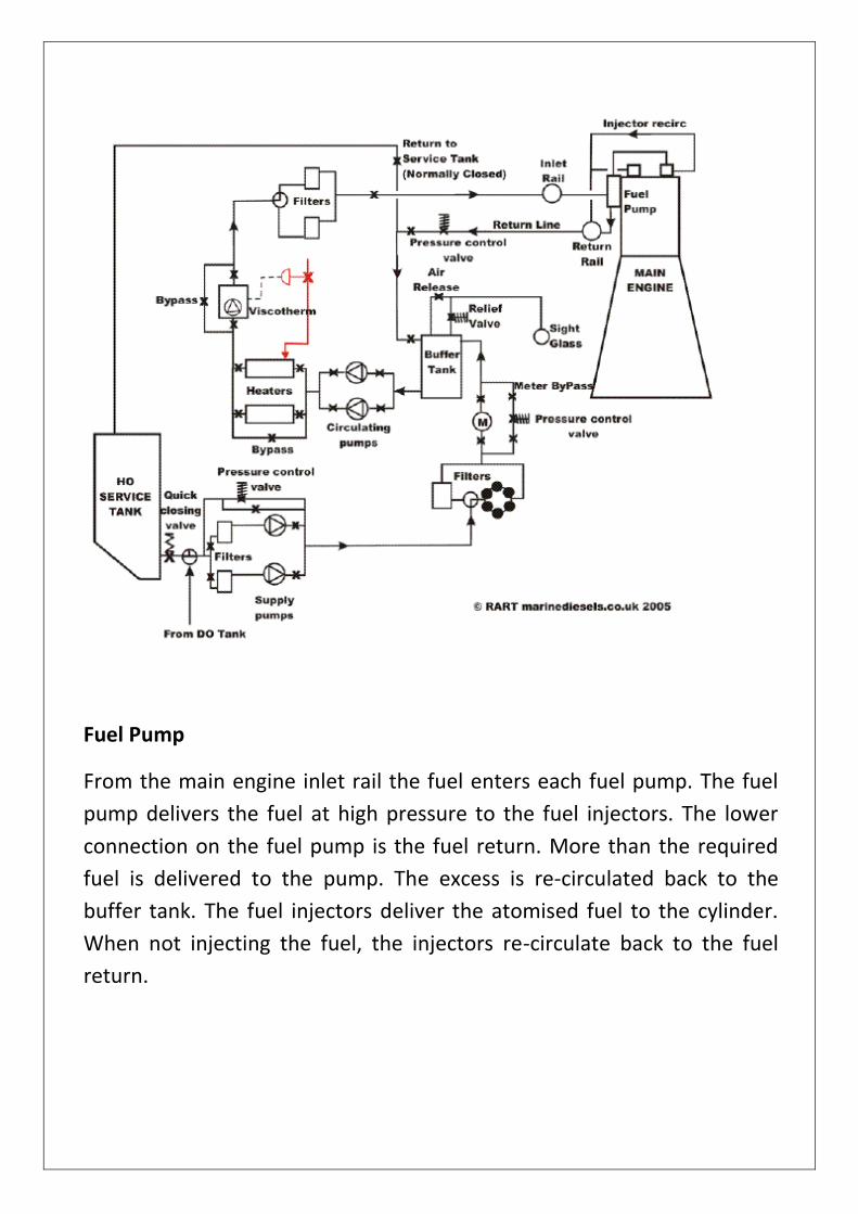
Fuel Pump
From the main engine inlet rail the fuel enters each fuel pump. The fuel
pump delivers the fuel at high pressure to the fuel injectors. The lower
connection on the fuel pump is the fuel return. More than the required
fuel is delivered to the pump. The excess is re-circulated back to the
buffer tank. The fuel injectors deliver the atomised fuel to the cylinder.
When not injecting the fuel, the injectors re-circulate back to the fuel
return.

Back flushing Filter
From the fuel pump, the fuel passes to a set of back flushing filters. The
parts contain the filter elements. The pods contain the filter elements.
When the filters start to clog up, a differential pressure sensor initiates a
back flushing routine so that the filters clean themselves. The back
flushing oil with the sediment from the filters drains to the fuel oil drank
tank from which it can be recovered and purified.

Fuel Oil Circulating Pump
From the buffer tank fuel oil circulating pumps pressurise the fuel to
about 8 bar through the heaters and to the engine.
Heaters
The oil is heated by the steam. The temperature of the oil is controlled by
a viscosity measuring device. The viscosity must be maintained at the
correct level for injection. On this particular system it is set at 16
centistokes.

COOLING SYSTEM OF DIESEL ENGINE
Combustion of the air-fuel mixture in the cylinders generates heat which
produces high pressure, to force the piston down in the power stroke.
Not all of this heat can be converted into useful work on the piston, and it
must be removed to prevent seizure of moving parts. This is the role of
the cooling system. Most engines are liquid-cooled.
A liquid-cooled system uses coolant - a fluid that contains special
chemicals mixed with water. Coolant flows through passages in the
engine, and through a radiator. The radiator accepts hot coolant from the
engine, and lowers its temperature. Air flowing around, and through the
radiator takes heat from the coolant. The lower-temperature coolant is
returned to the engine through a pump.
Air Cooling system
Air-cooling is common on smaller internal combustion engines. They may
be small but they still generate a lot of heat. It’s the air that does the
work of keeping them cool, so an air-cooling system is usually simple.
That’s useful on an engine where weight is important, and it works best
on the engine that are exposed to a high airflow.
Almost all motorcycles used to be air-cooled but modern motorcycles are
larger and more complex, and some are now liquid-cooled.
Some engines use what are called cooling fins. Their design makes the
exposed surface area as large as possible, which allows more heat energy
to radiate away, and be carried off in convection currents in the air. The
more air flows over the fins and more heat is carried away. For a vehicle
moving at speed, airflow over the engine is high. At low speeds or during
idling, heat builds up. Then the engine can use some help. Air should
always be able to flow over the engine effectively. One way to remove
heat is to use a fan, with shrouds and ducts to direct air to the cylinders.

There are many places to mount a fan and many ways to drive it. For
instance, in some engines it’s on the flywheel, driven by fan-belts off the
crankshaft.
Liquid Cooling system
In this very basic liquid-cooling system, a coolant is stored in a radiator,
and in the engine. As the engine heats up, a natural circulation starts, as
coolant rises through the engine block by convection. It passes through
the top hose, and into the radiator. Inside the radiator, heat is removed
from the coolant as it falls from the top to the bottom. When it reaches
the bottom, it returns to the engine through the lower radiator hose.
In modern cars, the engines are more powerful, and radiators are low and
wide, and a thermo-siphon process couldn’t move the coolant quickly
enough.
Instead, a water pump forces it through passages called waterjackets in
the engine block. It collects heat by conduction, and becomes hot itself.
Heated coolant then returns to the radiator for cooling. And the cycle is

repeated. Heat is removed from the engine, and dispersed. Preventing
overheating is one function of the cooling system
It also helps the engine reach its best operating temperature as soon as
possible. Every engine has a temperature at which it operates best. Below
this temperature, ignition and combustion can be difficult. Most engine
wear occurs during this warm-up period and most pollution too.
One function of the thermostat is to shorten the warming-up period. It
operates according to coolant temperature. When coolant is cold, it is
closed.
When a cold engine starts, coolant circulates within the engine block and
cylinder head and through a coolant bypass to the water pump inlet. It
can’t get to the radiator.
As the engine warms up, the coolant trapped in the engine gets hotter
and hotter.
This starts to open the thermostat, allowing hot coolant to flow to the
radiator.

LUBRICATION SYSTEM OF DIESEL ENGINE
The movement of various engine parts under high speed and load
conditions creates the requirement for an engine lubrication system.
Without some lubricant, friction between parts would quickly wear and
generate heat causing severe engine damage and eventually seizure. A
number of other lubrication system functions, while not obvious, are
critical to good engine operation and durability. Lubrication systems in a
diesel engine accomplish the following tasks:
1. Reduce friction between moving parts, which minimizes engine wear,
and the creation of heat.
2. Cools a variety of internal engine parts and removes some heat from
the engine.
3. Removes dirt, abrasives and contaminants from inside the engine.
4. Assists sealing of the combustion chamber by forming a film between
the piston rings and the cylinder wall.
5. Absorbs shock loads between bearings and gears thus, cushioning and
protecting engine parts while minimizing engine noise production.
6. Stores an adequate supply of oil for lubricating internal engine parts.
7. Minimizes corrosion of internal engine components

The lubrication system accomplishes some of the above tasks is a function
of a number of lubrication system components.
o Engine oil
o Oil pump

o Oil pan
o Oil cooler
o Oil filter(s)
o Pressure regulating and relief valves
o Oil level dipstick
Of all the components of a lubrication system, engine oil is the most
critical given the functions it accomplishes. Lubricating oil is primarily a
product of petroleum, commonly called mineral oil. Mineral oils will
contain a variety of different hydrocarbon molecules that have different
sizes, shapes and lubricating qualities. This means they will perform and
respond differently to heat, pressure and other engine operating factors.
Given the variations of potentially different oil characteristics and
qualities, the American Petroleum Institute (API) has developed
specifications to define what engine oil performance standards are. Two
distinct classifications of oils are recognized by API performance
specifications. S-series oils are designed to meet performance standards
for spark ignition systems while C-series oils meet compression ignition
engine performance requirements.
These API standards have progressively evolved since first conceived
during the 1940’s to meet advances to engine technology and engine
manufacturers’ performance requirements. Today’s oils are a highly
refined petroleum product with a package of chemicals called additives
to permit lubricating oil to meet engine operational requirements.