Embed Size (px)
Citation preview
Report from Vortex Induced Vibration Specialist Committee of the 26th ITTC
Presented by Halvor Lie Chairman of the comittee
• Members & meetings • Introduction • Review
– Numerical prediction models – Experimental methods
• Benchmark study • Nomenclature • Procedure for VIV and VIM testing • Technical conclusions
Members of the VIV Committee of the 26th ITTC
• Halvor Lie (Chairman, MARINTEK, Norway)
• Elena Ciappi (INSEAN), Italy)
• S. Huang (Universities of Strathclyde, UK)
• S. Hong (Moeri, Korea),
• Z. Zong (DUT, China)
Recommendation given to the committee 1. Update the state-of-the-art for predicting vortex induced vibrations
and motions emphasizing developments since the 2008 ITTC in various current profiles at ultra deep water. The update shall cover both small-diameter structures (e.g. risers) and large-diameter structures. (e.g. SPAR platforms)
2. Organize, conduct and report the results of benchmark VIV tests. Cooperate with OMAE on the benchmark activity.
3. Prepare standard nomenclature for VIV and VIM investigations
4. Write a procedure for VIV and VIM testing for marine applications
• CNR-INSEAN, Italy, November 2009 • Shanghai (OMAE 2010), China, June 2010 • University of Strathclyde, Glasgow, UK, February 2011
Three committee meetings

INTRODUCTION
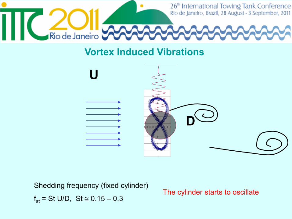
The cylinder starts to oscillate
Vortex Induced Vibrations
Shedding frequency (fixed cylinder)
fst = St U/D, St ≅ 0.15 – 0.3
U
D
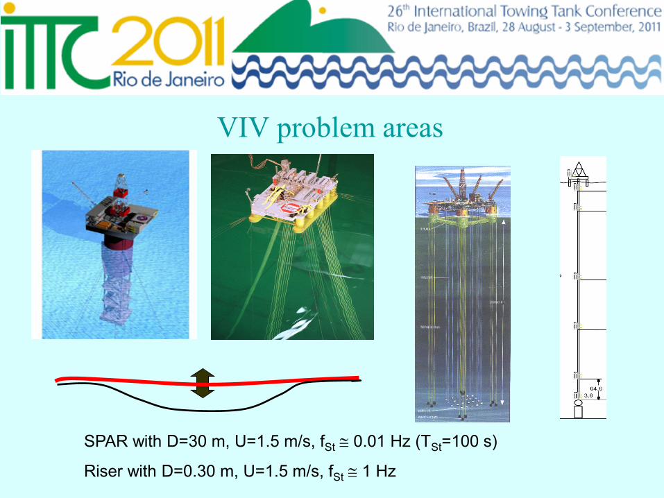
VIV problem areas
SPAR with D=30 m, U=1.5 m/s, fSt ≅ 0.01 Hz (TSt=100 s)
Riser with D=0.30 m, U=1.5 m/s, fSt ≅ 1 Hz
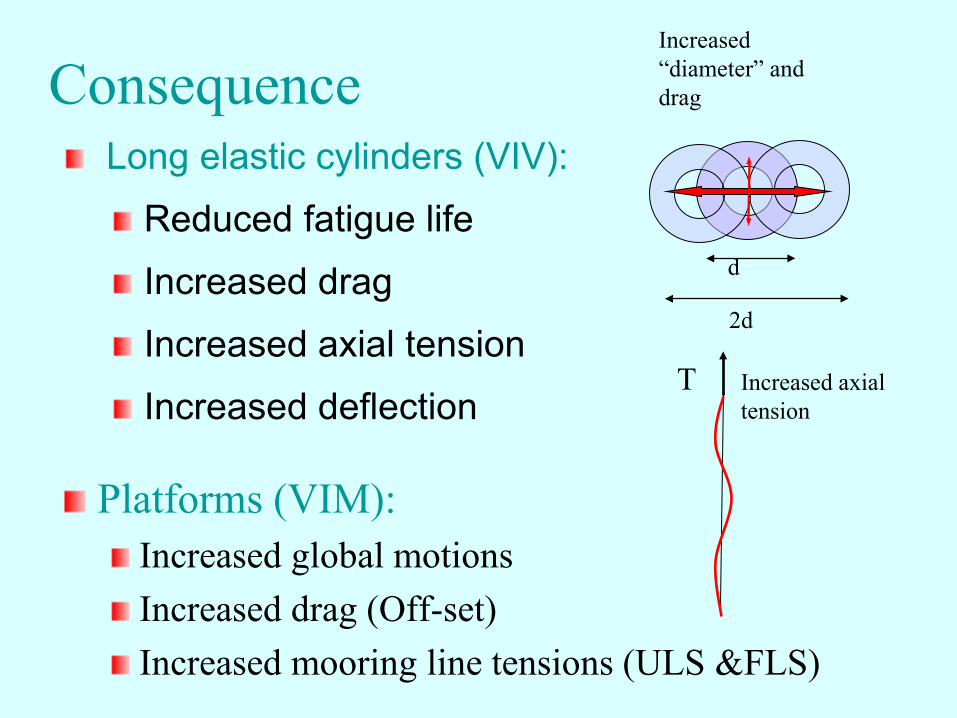
Consequence
Platforms (VIM): Increased global motions Increased drag (Off-set) Increased mooring line tensions (ULS &FLS)
Long elastic cylinders (VIV):
Reduced fatigue life
Increased drag
Increased axial tension
Increased deflection Increased axial tension
T
Increased “diameter” and drag
2d
d
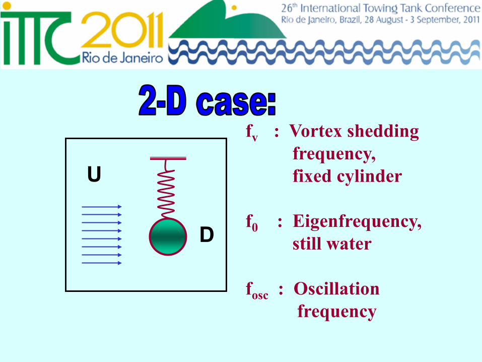
fv : Vortex shedding frequency, fixed cylinder f0 : Eigenfrequency, still water fosc : Oscillation frequency
U
D
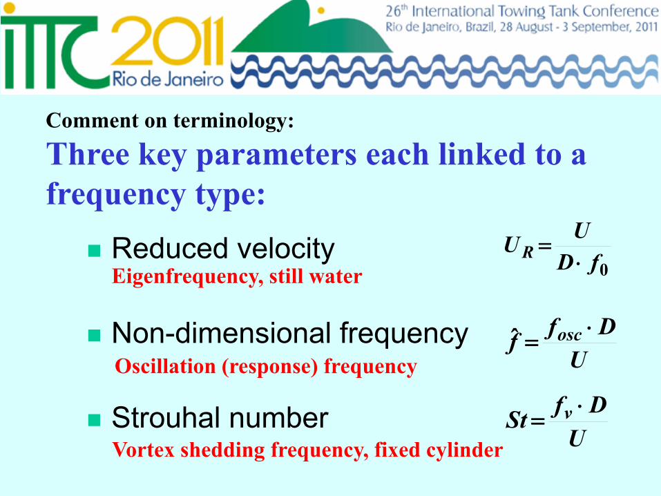
Comment on terminology:
Three key parameters each linked to a frequency type:
Reduced velocity
Non-dimensional frequency
Strouhal number
0fDUU R ⋅
=
UDff osc ⋅=ˆ
UDfSt v ⋅=
Eigenfrequency, still water
Oscillation (response) frequency
Vortex shedding frequency, fixed cylinder
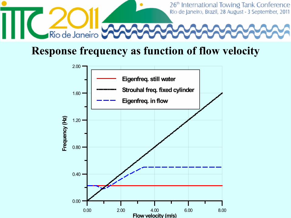
Response frequency as function of flow velocity
0.00 2.00 4.00 6.00 8.00Flow velocity (m/s)
0.00
0.40
0.80
1.20
1.60
2.00Fr
eque
ncy
(Hz)
Eigenfreq. still water
Strouhal freq. fixed cylinder
Eigenfreq. in flow
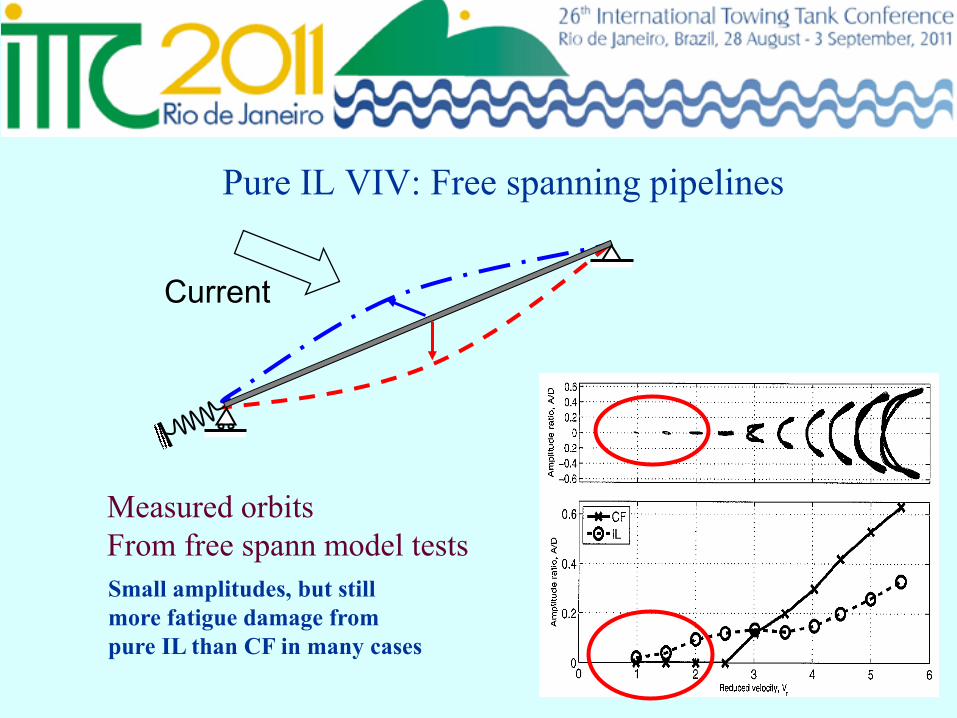
Pure IL VIV: Free spanning pipelines
Current
Measured orbits From free spann model tests Small amplitudes, but still more fatigue damage from pure IL than CF in many cases
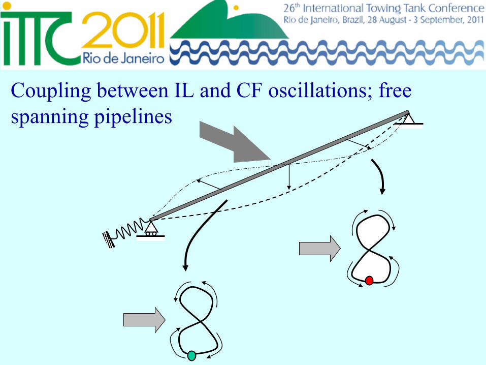
Coupling between IL and CF oscillations; free spanning pipelines
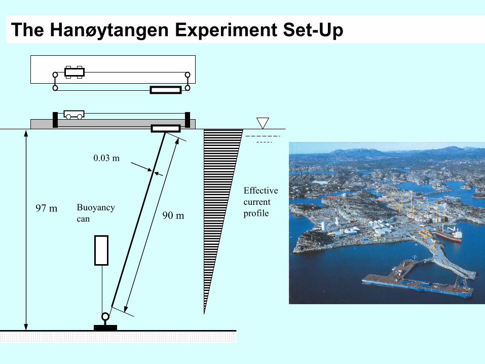
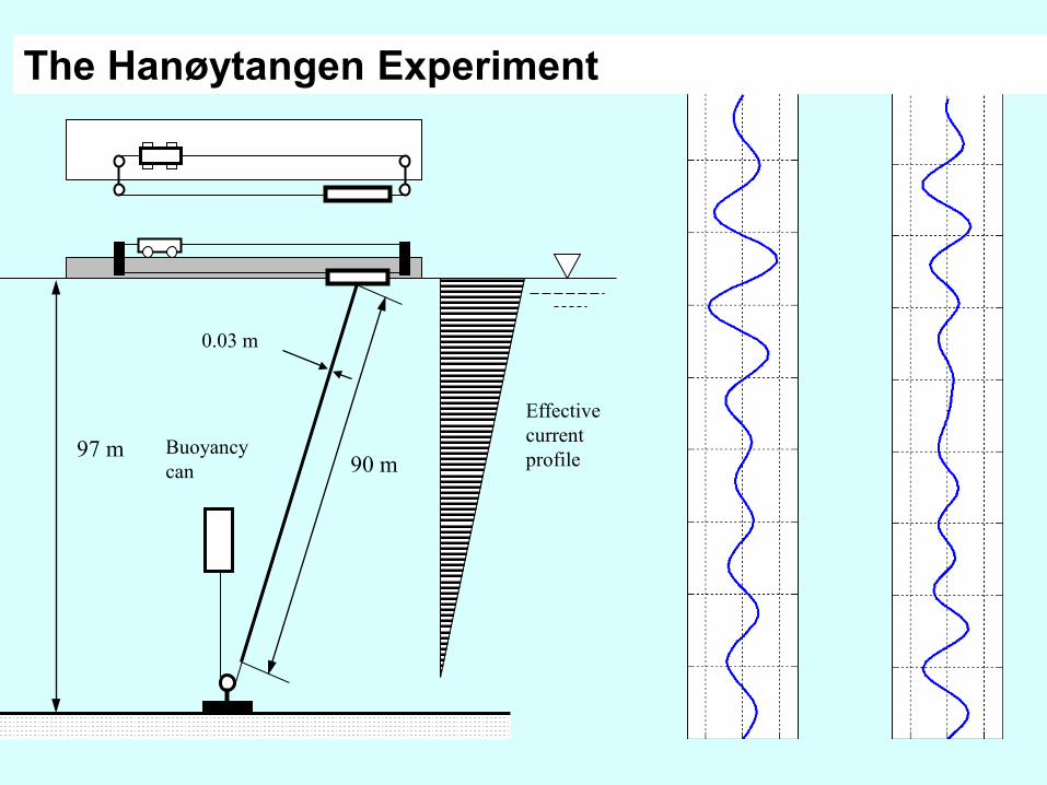
The Hanøytangen Experiment Set-Up
97 m 90 m
Buoyancy can
0.03 m
Effective current profile
97 m 90 m
Buoyancy can
0.03 m
Effective current profile
The Hanøytangen Experiment
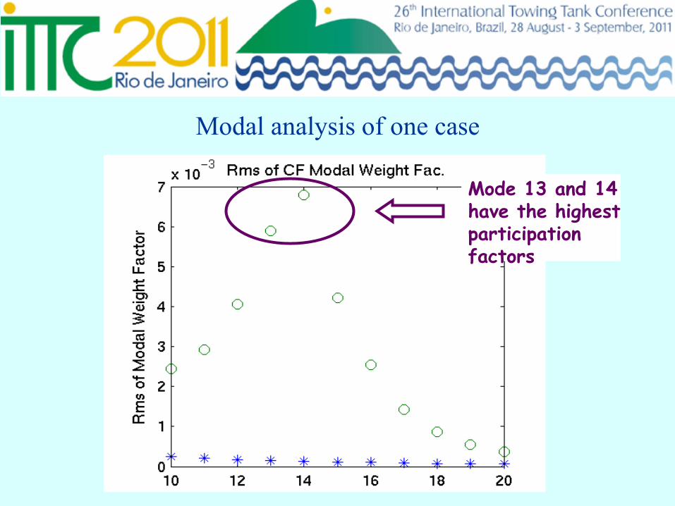
Modal analysis of one case
Mode 13 and 14 have the highest participation factors
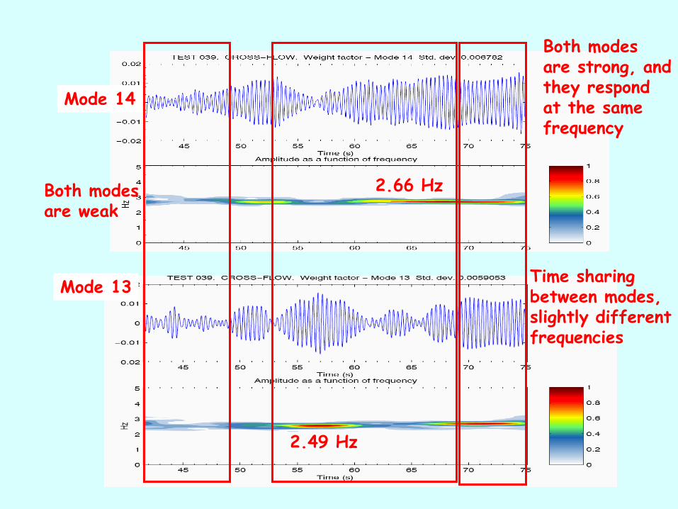
Mode 14
Mode 13 Time sharing between modes, slightly different frequencies
2.49 Hz
2.66 Hz
Both modes are strong, and they respond at the same frequency
Both modes are weak
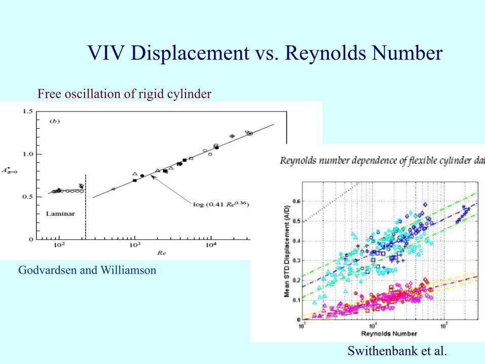
VIV Displacement vs. Reynolds Number
Godvardsen and Williamson
Swithenbank et al.
Free oscillation of rigid cylinder
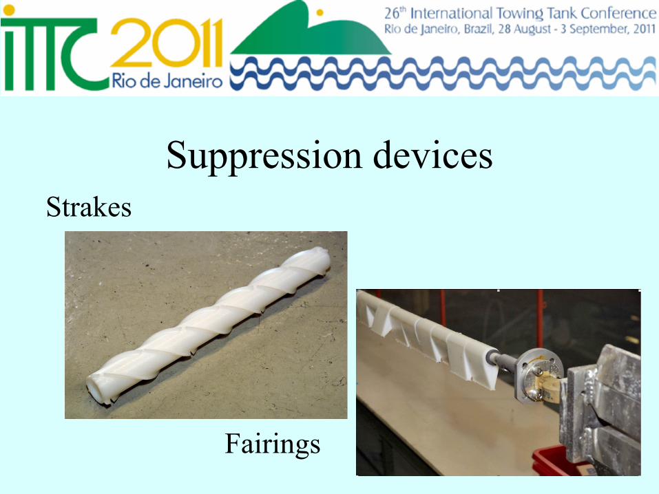
Suppression devices Strakes
Fairings
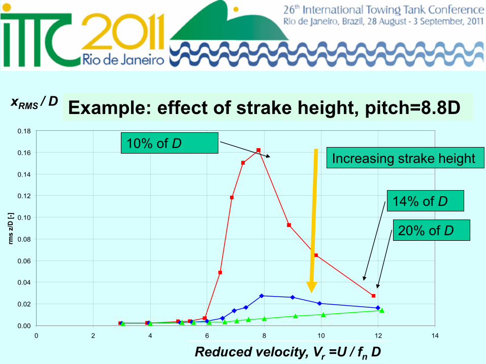
xRMS / D
0.00
0.02
0.04
0.06
0.08
0.10
0.12
0.14
0.16
0.18
0 2 4 6 8 10 12 14
Reduced velocity (-)
rms
z/D
[-]
P8.8_H10 P8.8_H14 P8.8_H20
Increasing strake height
Reduced velocity, Vr =U / fn D
20% of D
10% of D
14% of D
Example: effect of strake height, pitch=8.8D
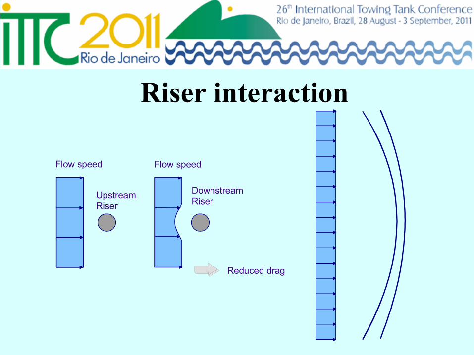
Riser interaction
Flow speed Flow speed
UpstreamRiser
DownstreamRiser
Reduced drag

REVIEW
• General trends • Numerical models
• CFD (Single & multiple cylinder configuration) • Wake oscillators • Semi-empirical methods
• Experiments • 2D tests • 3D tests • Fields measurements
Contents of review (last 3 years)
• Offshore oil and gas industry still have a strong interest in VIV of marine risers, free spanning pipelines, tethers and floating vessels.
• Great attention of research community, huge number of VIV papers both from industry and from academia
• VIV still not fully understood • Even less for multi-cylinders
General trends
Computational Fluid Dynamics • Prediction methods:
– Direct numerical simulations (DNS)
– Large Eddy Simulations (LES)
– Reynolds Averaged Navier-Stokes (RANS)
– Detached Eddy Simulations (DES) using finite difference, finite volume and finite element.
• Most of them are 2D or quasi 3D (strip theory)
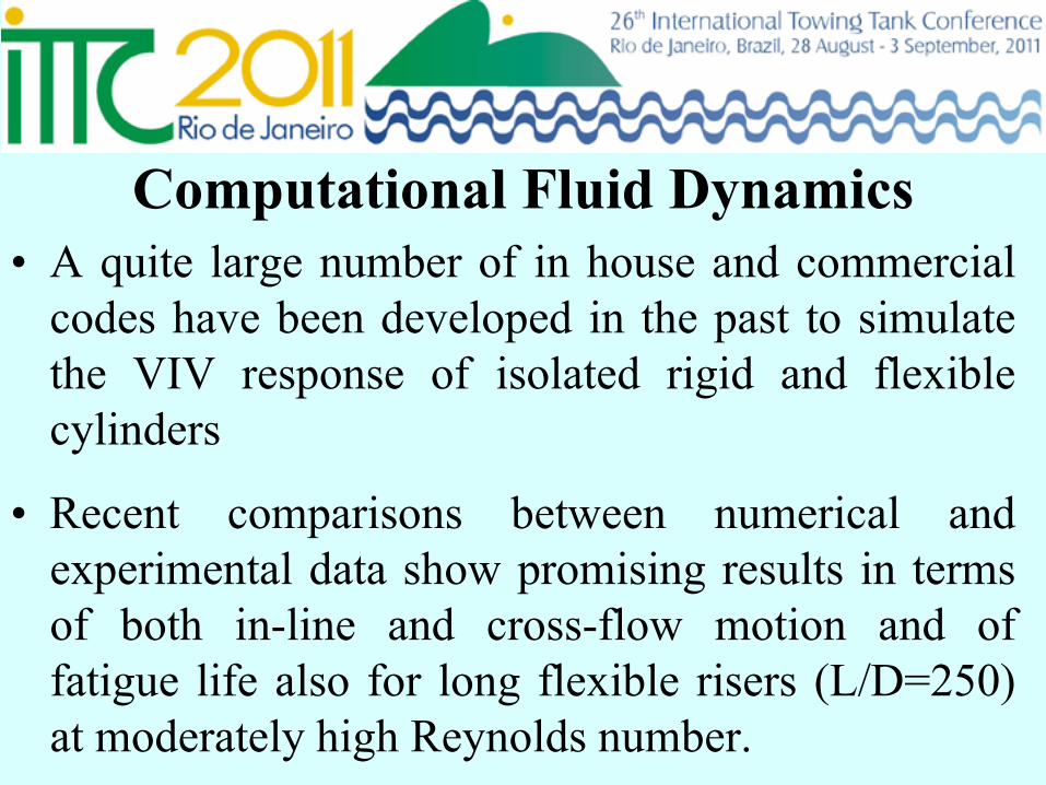
Computational Fluid Dynamics • A quite large number of in house and commercial
codes have been developed in the past to simulate the VIV response of isolated rigid and flexible cylinders
• Recent comparisons between numerical and experimental data show promising results in terms of both in-line and cross-flow motion and of fatigue life also for long flexible risers (L/D=250) at moderately high Reynolds number.
Computational Fluid Dynamics • In last three years a great attention has been
devoted to the study of multiple cylinder configurations.
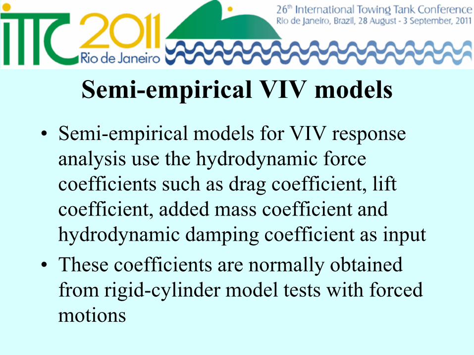
Semi-empirical VIV models • Semi-empirical models for VIV response
analysis use the hydrodynamic force coefficients such as drag coefficient, lift coefficient, added mass coefficient and hydrodynamic damping coefficient as input
• These coefficients are normally obtained from rigid-cylinder model tests with forced motions
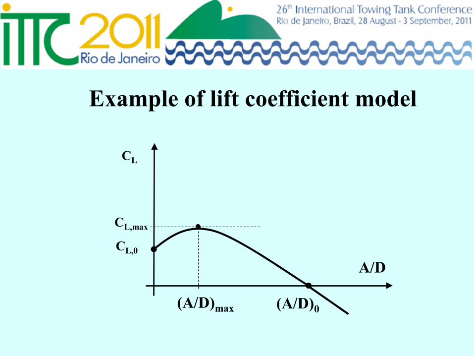
CL
A/D
(A/D)0 (A/D)max
CL,0
CL,max
Example of lift coefficient model
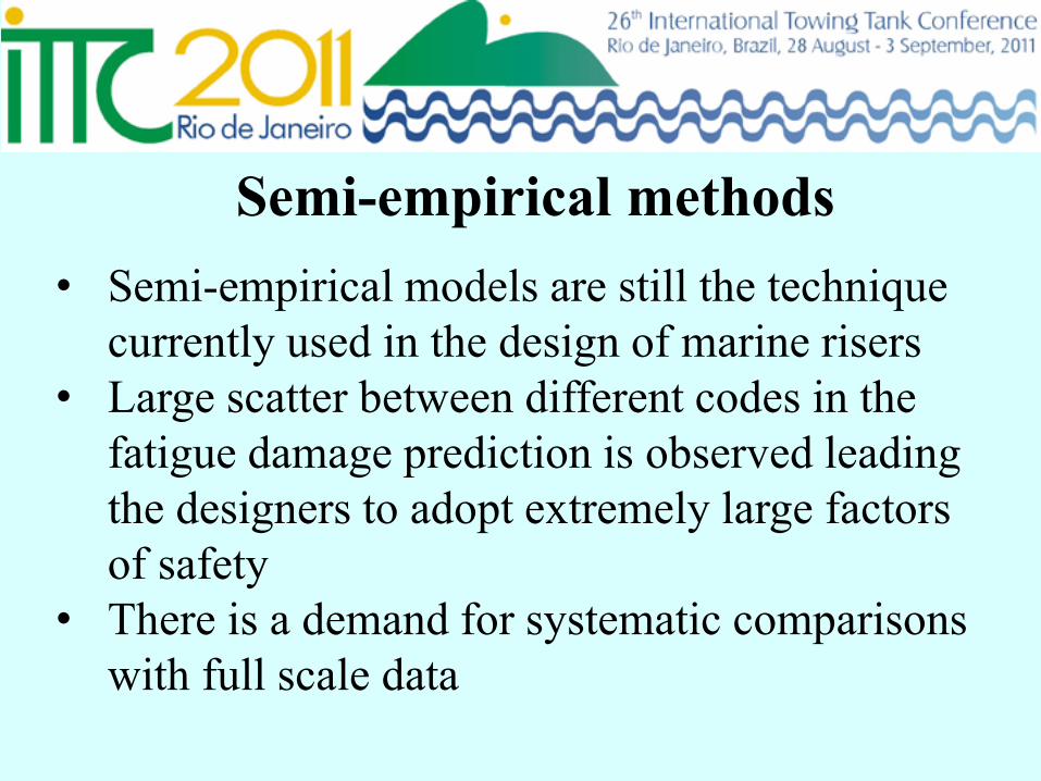
• Semi-empirical models are still the technique currently used in the design of marine risers
• Large scatter between different codes in the fatigue damage prediction is observed leading the designers to adopt extremely large factors of safety
• There is a demand for systematic comparisons with full scale data
Semi-empirical methods
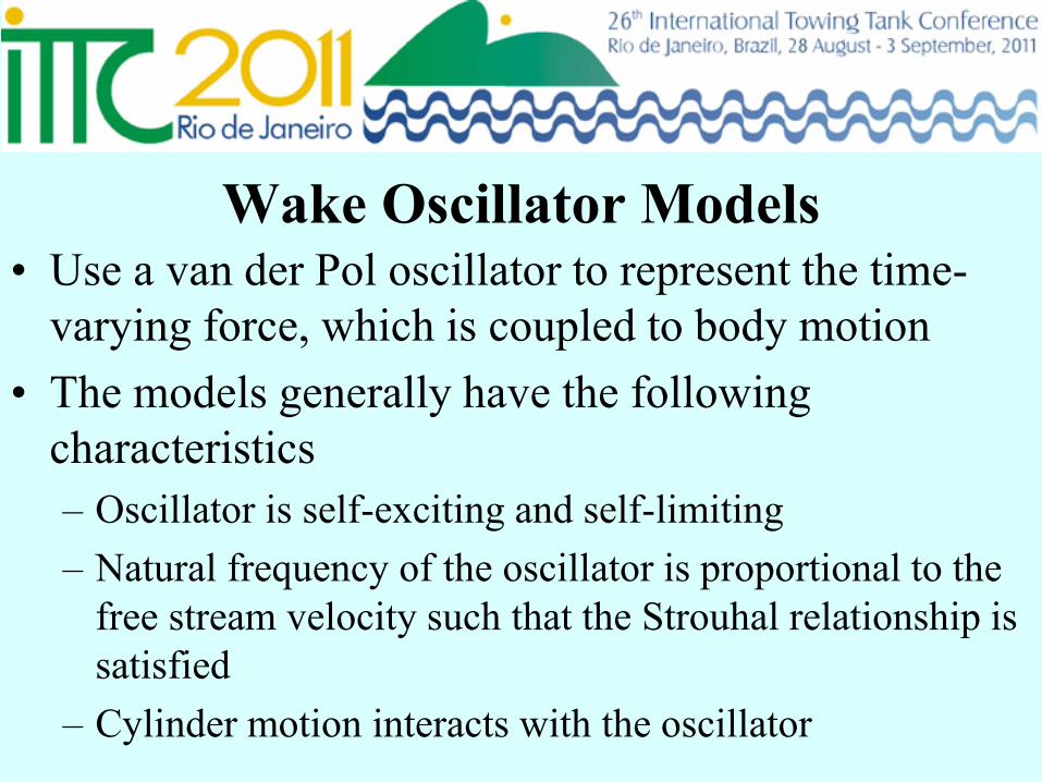
Wake Oscillator Models • Use a van der Pol oscillator to represent the time-
varying force, which is coupled to body motion • The models generally have the following
characteristics – Oscillator is self-exciting and self-limiting – Natural frequency of the oscillator is proportional to the
free stream velocity such that the Strouhal relationship is satisfied
– Cylinder motion interacts with the oscillator
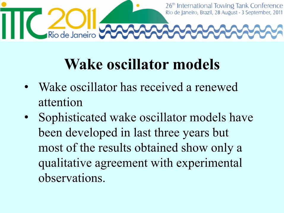
• Wake oscillator has received a renewed attention
• Sophisticated wake oscillator models have been developed in last three years but most of the results obtained show only a qualitative agreement with experimental observations.
Wake oscillator models
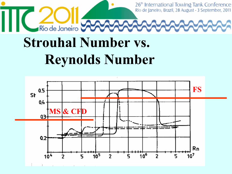
Strouhal Number vs. Reynolds Number
MS & CFD
FS
• Still a lack of high Reynolds number model test and full scale measurement data devoted to the determination of the coefficients used in the semi-empirical codes
• For validation of prediction tools and for further research of
VIV new experiments are needed for both single and multiple flexible cylinders at moderate and high Reynolds numbers for both bare cylinders and for cylinders with suppression devices (e.g. strakes and fairings)
Experimental studies
• Some flow field measurements performed by PIV technique are available for validation of numerical codes. New PIV experimental campaigns should be performed specifically devoted to CFD validation at high Reynolds number for single cylinder and at low and high Re for the multiple cylinder configurations.
Experimental studies

BENCHMARK STUDY
• To ascertain uncertainties in VIV model testing • To compare results from different tank organizations • To provide a set of authoritative experimental data for
verifying CFD results • ITTC VIV committee has establish cooperation with
OMAE on the benchmark activity, where ITTC can provide valuable experimental data to OMAE and OMAE provide benchmark of CFD data vs. measurement data
• The test results will be presented anonymous
Objectives of the proposed benchmark study
Specification of benchmark test – Vr range from 2 to16, preferably up to 20, with an increment 0.1 or less – L/D ratio 8-15 – Effective cylinder mass to displaced fluid mass ratio around 2 (within
range 1-3) – Cross-flow vibration only – No in-line nor rotational motion – Re number range (sub-critical) 15,000 < Rn <100,000 – Turbulence level low – Roughness of cylinder low – Low structural damping (in air) < 2% of the critical damping, preferably
< 1% – Endplates, or other means, to remove the end effects
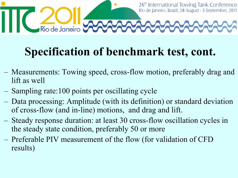
Specification of benchmark test, cont. – Measurements: Towing speed, cross-flow motion, preferably drag and
lift as well – Sampling rate:100 points per oscillating cycle – Data processing: Amplitude (with its definition) or standard deviation
of cross-flow (and in-line) motions, and drag and lift. – Steady response duration: at least 30 cross-flow oscillation cycles in
the steady state condition, preferably 50 or more – Preferable PIV measurement of the flow (for validation of CFD
results)
• The benchmark study initially 7 participants • 2 withdrew • 2 reported unforeseen delay
• By summer 2011 we have results from the
following institutions • MARINTEK, Norway • INSEAN, Italy • University of Strathclyde. UK
Participants
• The benchmark study initially 7 participants • 2 withdrew • 2 reported unforeseen delay
• By summer 2011 we have results from the following institutions • MARINTEK, Norway • INSEAN, Italy • University of Strathclyde. UK
Participants
Activity suggested to continue in ITTC27: NEW PARTICIPANT HEARTLY WELLCOME !
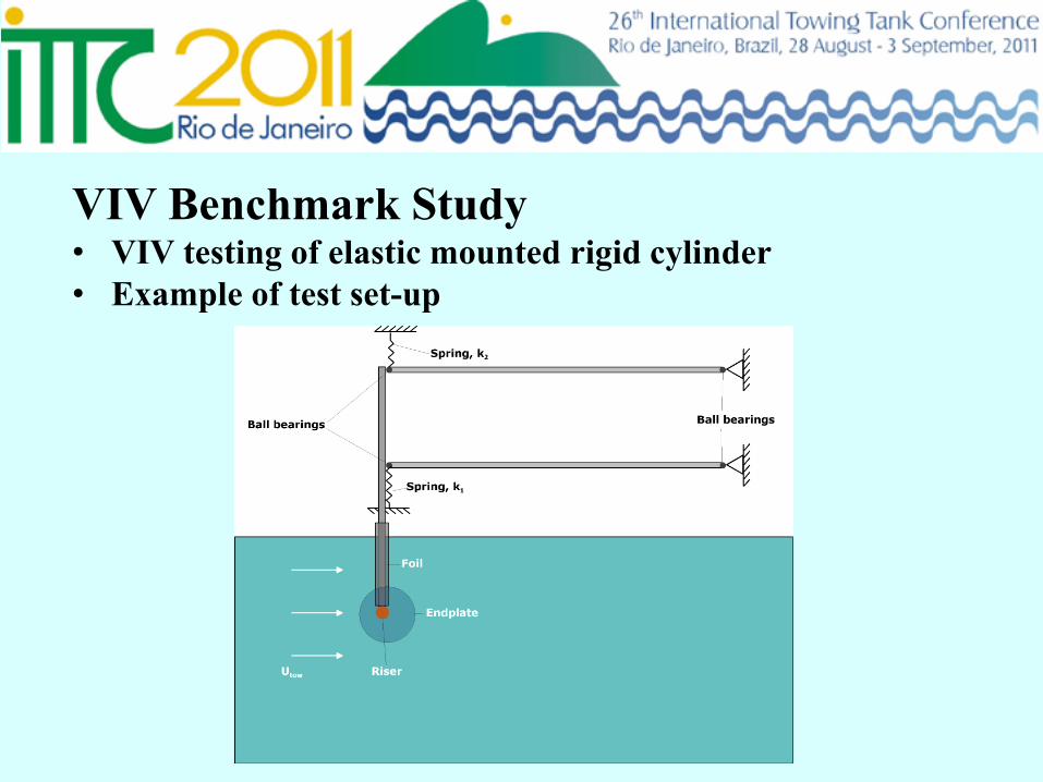
VIV Benchmark Study • VIV testing of elastic mounted rigid cylinder • Example of test set-up
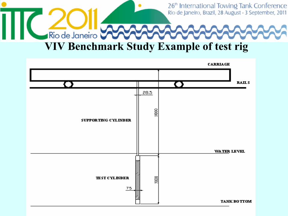
VIV Benchmark Study Example of test rig
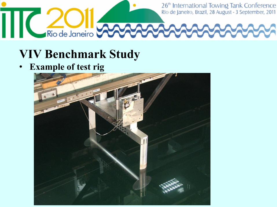
VIV Benchmark Study • Example of test rig
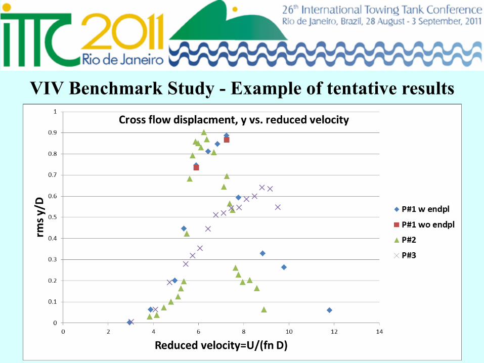
VIV Benchmark Study - Example of tentative results
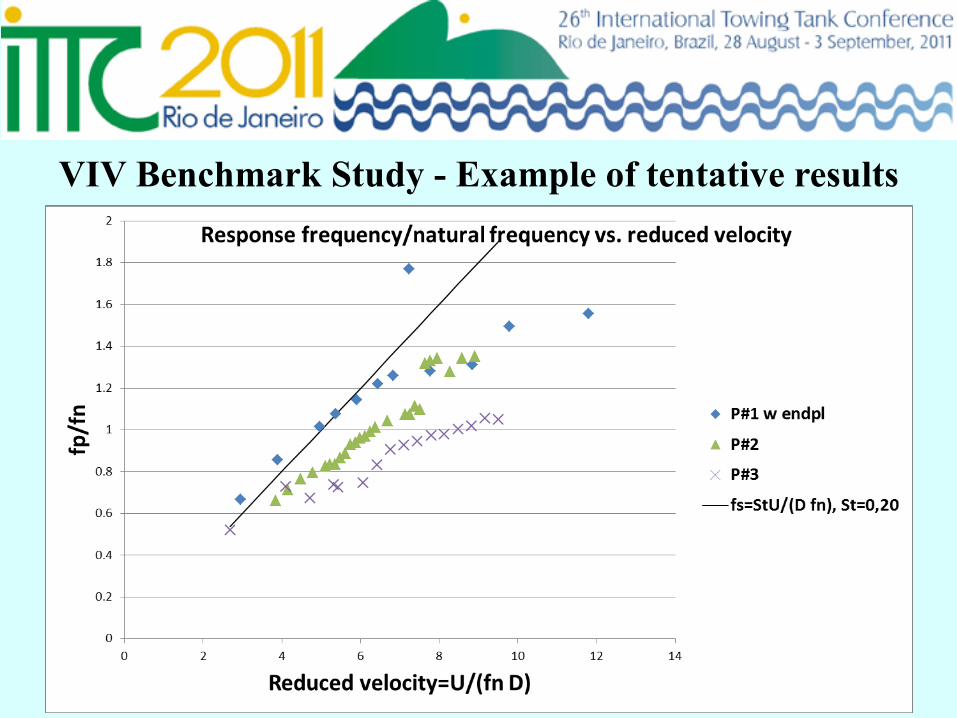
VIV Benchmark Study - Example of tentative results
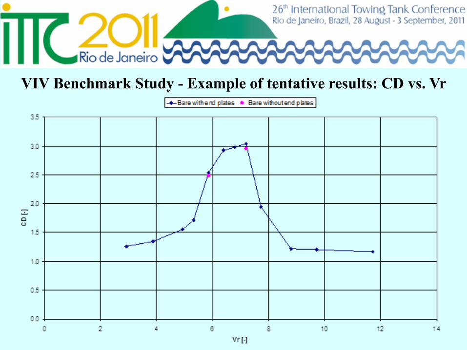
VIV Benchmark Study - Example of tentative results: CD vs. Vr

NOMENCLATURE
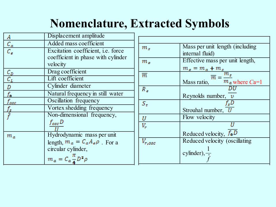
Displacement amplitude Added mass coefficient Excitation coefficient, i.e. force
coefficient in phase with cylinder velocity
Drag coefficient Lift coefficient
Cylinder diameter Natural frequency in still water
Oscillation frequency Vortex shedding frequency
Non-dimensional frequency,
Hydrodynamic mass per unit
length, . For a circular cylinder,
Mass per unit length (including
internal fluid) Effective mass per unit length,
Mass ratio, where Ca=1
Reynolds number,
Strouhal number, Flow velocity
Reduced velocity, Reduced velocity (oscillating
cylinder),f̂1
Nomenclature, Extracted Symbols
PROCEDURE FOR VIV AND VIM TESTING
Guideline (GL) for VIV and VIM Testing • Purpose of GL is to ensure that laboratory model test of
vortex induced responses are adequately performed and documented.
• VIV and VIM testing has much in common with floating offshore platform experiments. Hence it is recommended to also confer Procedure 7.5-02-07-03.1 Floating Offshore Platform Experiments
• The new GL focus on topics that are particular important for VIV/VIM testing
• Status: Draft prepared and sent to AC for comment
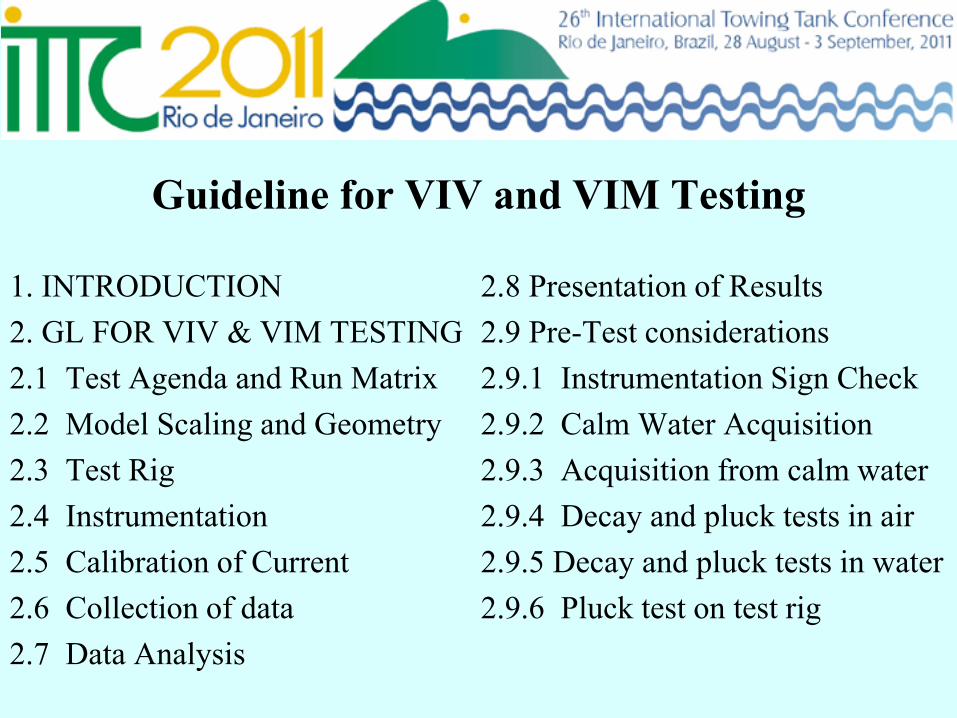
Guideline for VIV and VIM Testing
1. INTRODUCTION 2. GL FOR VIV & VIM TESTING 2.1 Test Agenda and Run Matrix 2.2 Model Scaling and Geometry 2.3 Test Rig 2.4 Instrumentation 2.5 Calibration of Current 2.6 Collection of data 2.7 Data Analysis
2.8 Presentation of Results 2.9 Pre-Test considerations 2.9.1 Instrumentation Sign Check 2.9.2 Calm Water Acquisition 2.9.3 Acquisition from calm water 2.9.4 Decay and pluck tests in air 2.9.5 Decay and pluck tests in water 2.9.6 Pluck test on test rig
Guideline for VIV and VIM Testing • Remaining work:
– Include effect of VIV/VIM due to marine growth – Test of riser interaction – Minor improvement of the text
• The 26 ITTC-VIV Committee recommends that the GL should be completed in the next ITTC period
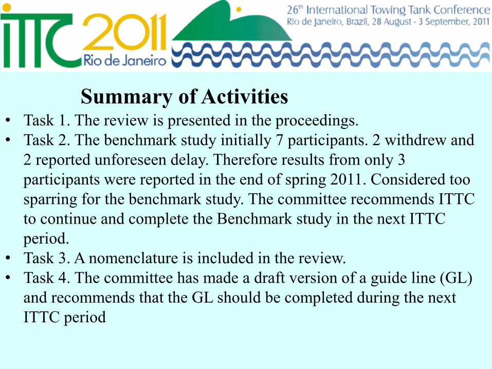
• Task 1. The review is presented in the proceedings. • Task 2. The benchmark study initially 7 participants. 2 withdrew and
2 reported unforeseen delay. Therefore results from only 3 participants were reported in the end of spring 2011. Considered too sparring for the benchmark study. The committee recommends ITTC to continue and complete the Benchmark study in the next ITTC period.
• Task 3. A nomenclature is included in the review. • Task 4. The committee has made a draft version of a guide line (GL)
and recommends that the GL should be completed during the next ITTC period
Summary of Activities
Thank you for your attention!

![EXPERIMENTS ON VORTEX-INDUCED VIBRATION …ijame.ump.edu.my/images/Volume_11 June 2015/31_Rahman and... · EXPERIMENTS ON VORTEX-INDUCED VIBRATION OF A VERTICAL ... Blevins [10],](https://img.dokumen.tips/doc/110x75/5b83b77d7f8b9a31608def8f/experiments-on-vortex-induced-vibration-ijameumpedumyimagesvolume11-june-201531rahman.jpg)