Embed Size (px)
Citation preview
Report
America’s Cup
Stormwater and Services Technical Report
for Resource Consent Application, Wynyard Hobson
Prepared for Panuku Development Auckland and the Ministry of Business Innovation and
Employment
Prepared by Beca Ltd (Beca)
April 2018
America's Cup Wynyard Hobson Stormwater and Services Report
Beca // 28 March 2018
3233847 // NZ1-15242902-18 0.18 // i
Revision History
Revision Nº Prepared By Description Date
1 Will Ingle, Joe Greene Draft Issue for Comment 29.03.2018
2 Will Ingle, Joe Greene Issued for Consent 11.04.2018
Document Acceptance
Action Name Signed Date
Prepared by Will Ingle, Joe Greene
11.04.2018
Reviewed by Stephen Priestley
11.04.2018
Approved by Stephen Priestley
11.04.2018
on behalf of Beca Ltd
© Beca 2018 (unless Beca has expressly agreed otherwise with the Client in writing).
This report has been prepared by Beca on the specific instructions of our Client. It is solely for our Client’s use for the purpose for which it is intended in accordance with the agreed scope of work. Any use or reliance by any person contrary to the above, to which Beca has not given its prior written consent, is at that person's own risk.
America's Cup Wynyard Hobson Stormwater and Services Technical Report
Beca // 28 March 2018
3233847 // NZ1-15242902-18 0.18 // ii
Executive Summary
The developments for the America’s Cup will require stormwater infrastructure and new services (water
supply, wastewater, power, lighting and communications).
The following Industrial and Trade Activities (ITA) and Hazardous Substances (HS) will also need to be
managed:
– ITA: boat repair at the syndicate bases.
– HS: limited quantities of Class 3 Flammable substances at the syndicate bases.
Stormwater Services
A number of site features and measures have been identified in relation to stormwater, potential ITA
discharge, and HS use associated with the proposed developments. These considerations and measures
are listed below:
Stormwater treatment devices designed to remove 75% of suspended sediment discharges, in
accordance with the Auckland Unitary Plan: Operative in Part (AUP:OP), will be provided.
Potential discharges from the sites will be managed through ITA Environmental and Hazardous
Substances Management Plans (ITA EHSMPs).
Potential ITA and HS Risks will be managed using the ITA Environmental and Hazardous Substances
Management Plans and Emergency Spill Response Plans (ESRPs).
There is no potential for flooding of, or damage or nuisance to, other properties.
The shoreline is protected by seawalls and the wharf discharges are at a distance from the shoreline
which minimises any potential for scour and erosion from the discharges.
Any potential adverse effects of stormwater and ITA discharge via stormwater in terms of land use,
discharge quantity and quality, and of HS use, storage and disposal are considered to be less than minor
based on the site features and provided the measures described above are implemented.
The proposed Wynyard Point works have minor beneficial effects compared to the existing, as there is a
reduction in potential for sediment discharge; due to the proposed modern stormwater treatment and car
park removal and a reduction in the storage of hazardous substances with the removal of the Stolthaven
South tank farm.
Other Services
Services (utilities) companies have been consulted and are supportive of the America’s Cup development.
Fire and Emergency New Zealand (FENZ) has had input to the proposed services for firefighting purposes.
Based on available information and discussions, the proposed connections for the syndicate bases have
adequate capacity to accommodate the anticipated demands outlined in this report. The proposed services
will be private lines owned, operated and maintained by Panuku Development Auckland (Panuku), as for the
existing Halsey Street Extension and Hobson Wharves.
For the proposed services, any adverse effects are considered to be less than minor on the basis that the
measures (including planning and coordination of works, temporary traffic management and methods such
combined trenches, directional drilling and routing of works) are undertaken.

America's Cup Wynyard Hobson Stormwater and Services Technical Report
Beca // 28 March 2018
3233847 // NZ1-15242902-18 0.18 // iii
The report identifies the potential for lighting effects from Business as Usual (BAU) and America’s Cup
Events for the Wynyard and Viaduct Harbour Precincts, caused by the potential for spill and glare from new
lighting, notably to sensitive sites such as apartments and hotels. A number of mitigation measures, including
use of zero tilt luminaries, and inclusion of event lighting procedures as part of an Event Management Plan,
are proposed. On the basis that these measures are incorporated into conditions of consent, and given the
existing environment against which the proposal must be assessed, the potential effects of lighting are less
than minor.
America's Cup Wynyard Hobson Stormwater and Services Technical Report
Beca // 28 March 2018
3233847 // NZ1-15242902-18 0.18 // page iv
Contents
Introduction .............................................................................................................. 1
1.1 Report Context ................................................................................................................................. 1
1.2 Purpose of Report ............................................................................................................................ 3
1.3 Report Structure .............................................................................................................................. 3
1.4 Proposed Use and Development ..................................................................................................... 4
2 Existing Environment ........................................................................................ 6
2.1 Summary of Harbour Environment .................................................................................................. 6
2.2 Stormwater Management ................................................................................................................ 6
2.3 Flooding and Overland Flow ............................................................................................................ 8
2.4 Industrial Trade Activity (ITA) Management .................................................................................... 9
2.5 Existing Services ............................................................................................................................. 9
3 Proposed Stormwater, ITA & HS Management ............................................. 13
3.1 ITA Categories ............................................................................................................................... 13
3.2 Best Practicable Option ................................................................................................................. 13
3.3 Stormwater Reticulation and Treatment ........................................................................................ 14
3.4 Environmental and Hazardous Substances Management Plans and Spill Response Plans ........ 17
3.5 Hazardous Substances .................................................................................................................. 18
4 Proposed Services .......................................................................................... 19
4.1 Water Supply ................................................................................................................................. 19
4.2 Wastewater .................................................................................................................................... 20
4.3 Power ............................................................................................................................................. 21
4.4 Lighting .......................................................................................................................................... 22
4.5 Communications ............................................................................................................................ 23
4.6 Storage Tanks and Product Lines ................................................................................................. 23
5 Assessment of Effects on the Environment ................................................. 24
5.1 Stormwater (and ITA) .................................................................................................................... 24
5.2 Effects of Services (excluding Lighting) ......................................................................................... 25
5.3 Lighting Effects .............................................................................................................................. 26
6 Mitigation, Monitoring and Draft Conditions of Consent ............................. 28
7 Summary and Conclusions ............................................................................ 29
7.1 General .......................................................................................................................................... 29
7.2 Effects of Marine Works ................................................................................................................. 29
7.3 Effects of Wynyard Point Works .................................................................................................... 30
America's Cup Wynyard Hobson Stormwater and Services Technical Report
Beca // 28 March 2018
3233847 // NZ1-15242902-18 0.18 // page v
Appendices
Appendix A
ITA Emergency Spill Response Plan - Draft Table of Contents
Appendix B
ITA Environmental and Hazardous Substances Management Plan - Draft Table of Contents
Appendix C
Stormwater Treatment Concept Design Calculation & Sketch
Appendix D
Correspondence from Services Organisations & FENZ
America's Cup Wynyard Hobson Stormwater and Services Technical Report
Beca // 28 March 2018
3233847 // NZ1-15242902-18 0.18 // page 1
Introduction
1.1 Report Context
Panuku Development Auckland (Panuku), as Auckland Council's lead delivery agency, has been tasked with
providing waterfront infrastructure to host the America’s Cup Events and associated regattas in Auckland.
The Crown has agreed to provide significant funding to support the hosting of the Events in Auckland. The
Ministry of Business, Innovation and Employment (MBIE) is the Crown's lead business-facing agency,
responsible for New Zealand Major Events.
Beca Limited (Beca) has previously been commissioned by Panuku to prepare reports for the initial A36
Wynyard Basin application and corresponding Ferry and Fishing Industry Relocation Facility.
Beca has now been commissioned by Panuku and MBIE to undertake technical studies and engineering
concept drawings in relation to the new proposal, called "Wynyard Hobson".
Consents are sought for the use and development associated with holding the 36th America’s Cup in
December 2020 to May 2021 and any subsequent events within a 10 year period (each over a six-month
“event” period), and to construct, use and operate up to seven syndicate bases within the 10 year period.
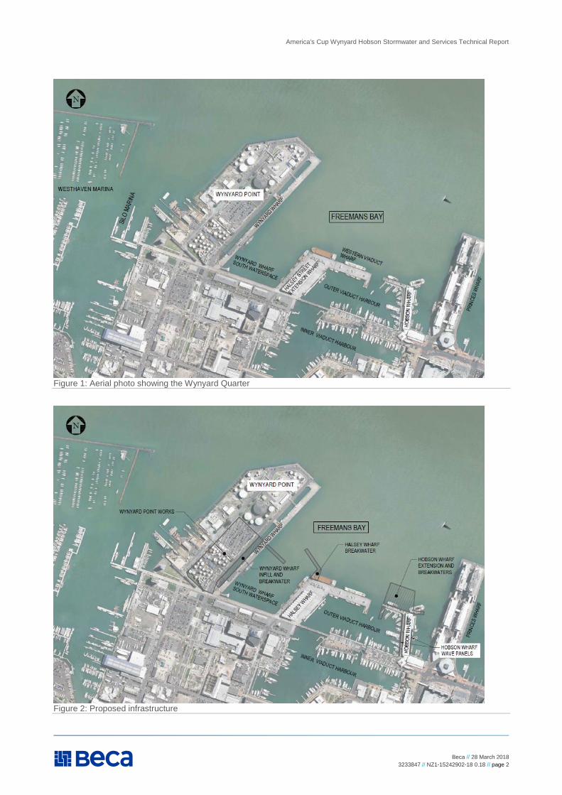
The seven America’s Cup bases are proposed in and around Freeman’s Bay, which is located along part of
Auckland’s City Centre waterfront. This includes Wynyard Point, Hobson Wharf, a 74m extension to Hobson
Wharf, Halsey Wharf (comprising the Halsey Street Extension Wharf and Western Viaduct Wharf) and
Wynyard Wharf, including the surrounding land and waterspace.
America's Cup Wynyard Hobson Stormwater and Services Technical Report
Beca // 28 March 2018
3233847 // NZ1-15242902-18 0.18 // page 2
Figure 1: Aerial photo showing the Wynyard Quarter
Figure 2: Proposed infrastructure
America's Cup Wynyard Hobson Stormwater and Services Technical Report
Beca // 28 March 2018
3233847 // NZ1-15242902-18 0.18 // page 3
For the purpose of the RMA assessment, the effects have been assessed on the basis that the two bulk
liquid operators where Bases E, F and G are proposed have vacated the sites in advance of the event.
The proposal is made on the basis that part of Brigham Street will be permanently stopped. This will be
achieved through a separate process. For the purpose of the RMA assessment, the effects of the road
closure including works in the road have been assessed, but not the effects of the proposal on the road as it
currently exists. The proposal includes a new road connection north of syndicate Base C to maintain a
connection between Brigham Street and Hamer Street.
To support this resource consent application, Beca has prepared a suite of reports and drawings:
America’s Cup – Wynyard Hobson – Physical Infrastructure Technical Report
America’s Cup – Wynyard Hobson - Geotechnical Report.
America’s Cup – Wynyard Hobson - Groundwater Technical Report.
America’s Cup – Wynyard Hobson - Preliminary Site Investigations (Contamination) and Draft
Remediation Action Plan.
America’s Cup – Wynyard Hobson - Coastal Processes and Dredging Technical Report.
America’s Cup – Wynyard Hobson - Stormwater and Services Technical Report (this report).
America’s Cup – Wynyard Hobson - Traffic and Transport Technical Report.
America’s Cup – Wynyard Hobson - Fire and Evacuation Assessment.
America’s Cup – Wynyard Hobson - Marine Traffic Survey.
America’s Cup – Wynyard Hobson - Engineering Concept Drawings.
Each of the individual technical reports should be read in conjunction with the pack of Engineering Concept
Drawings to which reference is made as applicable. Reports by other specialists for the resource consent
application cover:
Landscape, visual impact and natural character (Boffa Miskell).
Urban design (McIndoe Urban).
Ecology, sediment and water quality (Golder Associates).
Noise and vibration (Marshall Day Acoustics).
Navigation and recreational vessels (Navigatus).
Environmental risk (Sherpa Consulting).
Hazardous substances (4Sight)
Planning (Assessment of Environmental Effects) (Unio Environmental).
1.2 Purpose of Report
The purpose of this report is to document the existing environment and the assessment of effects in relation
to stormwater, industrial and trade activities (ITA), hazardous substances (HS) and existing services (water
supply, wastewater, power etc.). Necessary new services for the America’s Cup concept design are
described. The report forms part of the resource consent application for Wynyard Hobson.
1.3 Report Structure
This report is structured as follows:
Section 1: Introduction, including roles, reporting context and overview of proposed development.
America's Cup Wynyard Hobson Stormwater and Services Technical Report
Beca // 28 March 2018
3233847 // NZ1-15242902-18 0.18 // page 4
Section 2: Existing Environment, which gives an overview of the harbour environment and the existing
services as well as the present stormwater management approach at the sites.
Section 3: Proposed Stormwater, ITA & HS Management sets out the proposed approach to managing
HS used on the sites, stormwater, and potential discharge of contaminants from ITA.
Section 4: Proposed Services covers the proposed approach to providing services for the development.
Section 5: Assessment of Environmental Effects describes the effects of stormwater and providing new
services.
Section 6: Mitigation and Monitoring outlines proposed measures and conditions of consent.
Section 7: Conclusions.
Appendix A: ITA Emergency Spill Response Plans (ESRP) contains the draft table of contents for the
proposed development, based on Auckland Unitary Plan: Operative in Part (AUP:OP) requirements.
Appendix B: ITA Environmental and Hazardous Substances Management Plans (EHSMP) contains the
draft table of contents for the proposed development, based on AUP:OP requirements.
Appendix C: Stormwater Treatment Concept Design Calculation & Sketch includes the preliminary
calculations for sizing the proposed treatment devices and sketch of a typical device.
Appendix D: Correspondence from Services Organisations and FENZ comprises correspondence from
these organisations following discussion with the project team.
The master drawing set contains drawings of the existing providing services at the development sites
(Existing Services Drawings 1 to 7); and concept drawings of the proposed development and associated
stormwater and services provisions (Proposed Services Drawings 1 to 7).
1.4 Proposed Use and Development
The proposal involves the following three main elements (as described more fully in the Assessment of
Environmental Effects (prepared by Unio Environmental) and as shown in the drawings and outlined in the
reports which form part of this application:
1. Use and operation of land and water space associated with the 36th America’s Cup event to be held in
the six month period from December 2020 to May 2021 (including pack in and pack out of land based
and water based activities/structures) and any subsequent America’s Cup event(s) held (with a six
month period each) during the 10 year period from the commencement of consent.
2. The use and operation of the syndicate bases (buildings and associated yards on land/wharves and
water space) for a period up to 10 years from the commencement of consent.
3. The construction and establishment of the wharves, piles, berths, buildings, other structures, and
related works, services and access (including ground improvement works, contamination
management, earthworks) including all event related structures and services. The infrastructure will be
provided on a temporary and permanent basis, as follows:
a. Temporary (up to 10 years)
i. Syndicate base buildings B to G;
ii. Use of all syndicate base buildings (including ETNZ use of VEC);
iii. Wynyard Wharf ‘wharf infill’ to be removed (no less than 50%);
iv. Event-related structures (up to 6 month(s) for each event period); and
v. Marine and Port structures/facilities within the Wynyard Wharf South Waterspace and Outer Viaduct Harbour.
b. Permanent:
America's Cup Wynyard Hobson Stormwater and Services Technical Report
Beca // 28 March 2018
3233847 // NZ1-15242902-18 0.18 // page 5
i. A 74m extension to Hobson Wharf including a 35-year CMA occupation permit for this structure;
ii. Four new breakwaters located as follows:
An 81m breakwater east of Wynyard Wharf (Wynyard east);
A 39m and 84m breakwater northwest of Halsey Wharf (Halsey west)
A 35m breakwater east of Hobson Wharf (Hobson east) including a 35-year CMA occupation permit for this structure;
A 42m breakwater south of Hobson Wharf (Hobson south) including a 35-year CMA occupation permit for this structure.
iii. Wave panels on Hobson Wharf (including the 74m extension) and Halsey Wharf;
iv. Wynyard Wharf ‘wharf infill’ to remain (up to 50%); and
v. Physical modifications to the VEC including the following key changes:
Removal of the eastern public access ramp to the northern public viewing deck and replacement with a lift on the western side of the building;
Modifications to the eastern façade of the building to construct new doors to facilitate for use as a syndicate base;
The additional of a mezzanine floor at the northern end of the building for a sail loft;
The addition of a new balcony on the eastern facade.
America's Cup Wynyard Hobson Stormwater and Services Technical Report
Beca // 28 March 2018
3233847 // NZ1-15242902-18 0.18 // page 6
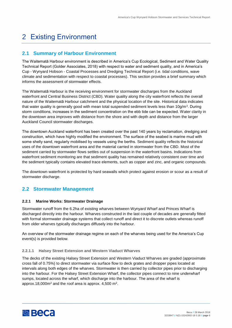
2 Existing Environment
2.1 Summary of Harbour Environment
The Waitematā Harbour environment is described in America’s Cup Ecological, Sediment and Water Quality
Technical Report (Golder Associates, 2018) with respect to water and sediment quality, and in America’s
Cup - Wynyard Hobson - Coastal Processes and Dredging Technical Report (i.e. tidal conditions, wave
climate and sedimentation with respect to coastal processes). This section provides a brief summary which
informs the assessment of stormwater effects.
The Waitematā Harbour is the receiving environment for stormwater discharges from the Auckland
waterfront and Central Business District (CBD). Water quality along the city waterfront reflects the overall
nature of the Waitematā Harbour catchment and the physical location of the site. Historical data indicates
that water quality is generally good with mean total suspended sediment levels less than 10g/m3. During
storm conditions, increases in the sediment concentration on the ebb tide can be expected. Water clarity in
the downtown area improves with distance from the shore and with depth and distance from the larger
Auckland Council stormwater discharges.
The downtown Auckland waterfront has been created over the past 140 years by reclamation, dredging and
construction, which have highly modified the environment. The surface of the seabed is marine mud with
some shelly sand, regularly mobilised by vessels using the berths. Sediment quality reflects the historical
uses of the downtown waterfront area and the material carried in stormwater from the CBD. Most of the
sediment carried by stormwater flows settles out of suspension in the waterfront basins. Indications from
waterfront sediment monitoring are that sediment quality has remained relatively consistent over time and
the sediment typically contains elevated trace elements, such as copper and zinc, and organic compounds.
The downtown waterfront is protected by hard seawalls which protect against erosion or scour as a result of
stormwater discharge.
2.2 Stormwater Management
2.2.1 Marine Works: Stormwater Drainage
Stormwater runoff from the 6.2ha of existing wharves between Wynyard Wharf and Princes Wharf is
discharged directly into the harbour. Wharves constructed in the last couple of decades are generally fitted
with formal stormwater drainage systems that collect runoff and direct it to discrete outlets whereas runoff
from older wharves typically discharges diffusely into the harbour.
An overview of the stormwater drainage regime on each of the wharves being used for the America’s Cup
event(s) is provided below.
2.2.1.1 Halsey Street Extension and Western Viaduct Wharves
The decks of the existing Halsey Street Extension and Western Viaduct Wharves are graded (approximate
cross fall of 0.75%) to direct stormwater via surface flow to deck grates and dropper pipes located at
intervals along both edges of the wharves. Stormwater is then carried by collector pipes prior to discharging
into the harbour. For the Halsey Street Extension Wharf, the collector pipes connect to nine underwharf
sumps, located across the wharf, which discharge into the harbour. The area of the wharf is
approx.18,000m2 and the roof area is approx. 4,500 m2.
America's Cup Wynyard Hobson Stormwater and Services Technical Report
Beca // 28 March 2018
3233847 // NZ1-15242902-18 0.18 // page 7
2.2.1.2 Hobson Wharf
Runoff from the paved surfaces on Hobson Wharf discharges diffusely into the harbour without any formal
collection system. Roof runoff from the Maritime Museum, which is located on Hobson Wharf, is collected in
roof gutters and then discharged directly to the harbour via downpipes and dropper pipes. The area of the
wharf is approx. 5,700 m2 and the roof area is approx. 3,500 m2.
2.2.1.3 Wynyard Wharf
There is no formal stormwater drainage system on Wynyard Wharf and runoff discharges diffusely from the
wharf, directly into the harbour. At the bulk liquids loading facility there is a bunded area which discharges to
an oil separator. The area of the wharf is approx. 9,500 m2.
A 2,750mm oval stormwater pipe (in situ concrete) discharges through North Wharf Wall, at the southern end
of Wynyard Wharf. This carries flows from the Freemans Bay catchment.
2.2.2 Wynyard Point Works: Stormwater Drainage
2.2.2.1 Wynyard Point
Bases C-G are on Wynyard Point, bounded by Hamer Street on the western side and by existing bulk liquid
storage facilities (tank farms) to the north and Silo Park to the south. To provide connectivity between the
syndicate base buildings and the water loadout area a section of Brigham Street will be stopped and
incorporated into the base areas.
The location of Bases C-G has been predominantly used for the storage of bulk liquids but some areas have
been cleared of storage tanks and are now used for the parking of cars and general storage. With the
existing Stolthaven South and Bulk Storage Terminals (BST) tanks due to be cleared in advance of the
tenants vacating, it is anticipated the site will be free of all tanks, foundations and associated pipework prior
to construction.
In total the site covers an area of approximately 2.4ha and is almost 100% paved. Stormwater runoff is
generally collected via a variety of private catch pits and drainage channels and directed to the public
stormwater drainage network prior to discharge directly into the harbour. The bunded areas within the
Stolthaven South and BST tank farms are understood to discharge via/to oil separators.
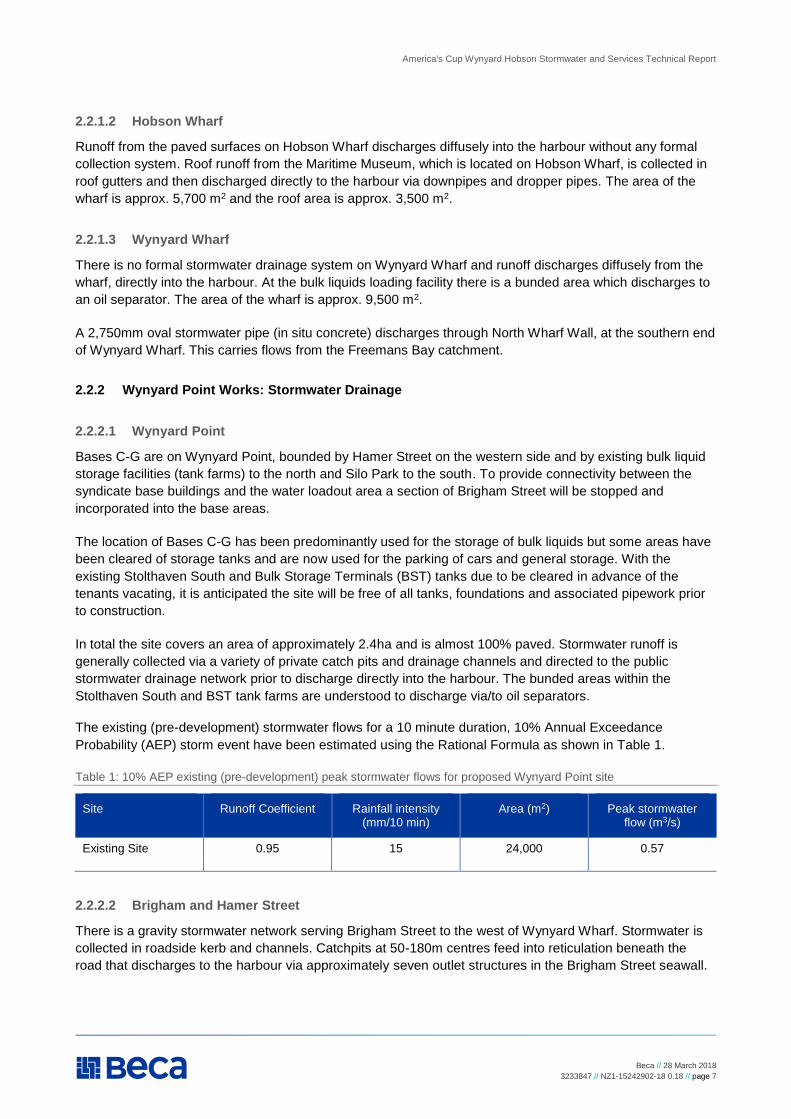
The existing (pre-development) stormwater flows for a 10 minute duration, 10% Annual Exceedance
Probability (AEP) storm event have been estimated using the Rational Formula as shown in Table 1.
Table 1: 10% AEP existing (pre-development) peak stormwater flows for proposed Wynyard Point site
Site Runoff Coefficient Rainfall intensity (mm/10 min)
Area (m2) Peak stormwater flow (m3/s)
Existing Site 0.95 15 24,000 0.57
2.2.2.2 Brigham and Hamer Street
There is a gravity stormwater network serving Brigham Street to the west of Wynyard Wharf. Stormwater is
collected in roadside kerb and channels. Catchpits at 50-180m centres feed into reticulation beneath the
road that discharges to the harbour via approximately seven outlet structures in the Brigham Street seawall.
America's Cup Wynyard Hobson Stormwater and Services Technical Report
Beca // 28 March 2018
3233847 // NZ1-15242902-18 0.18 // page 8
Hamer Street is served by a stormwater network similar to that described for Brigham Street. However, the
reticulation runs northward to a 600mm diameter outfall at the northern end of Wynyard Point.
2.3 Flooding and Overland Flow
2.3.1 Marine Works: Flooding and Overland Flowpaths
2.3.1.1 Halsey Street Extension, Western Viaduct and Hobson Wharves
As the existing wharves are located over water, at the seaward limit of the catchments, there are no flooding
and overland flow paths associated with them. Further, the Auckland Council GIS mapping does not identify
any overland flow paths or flood prone areas immediately landward of the existing wharves (i.e. no
immediate areas that might be affected by proposed additional wharf structures).
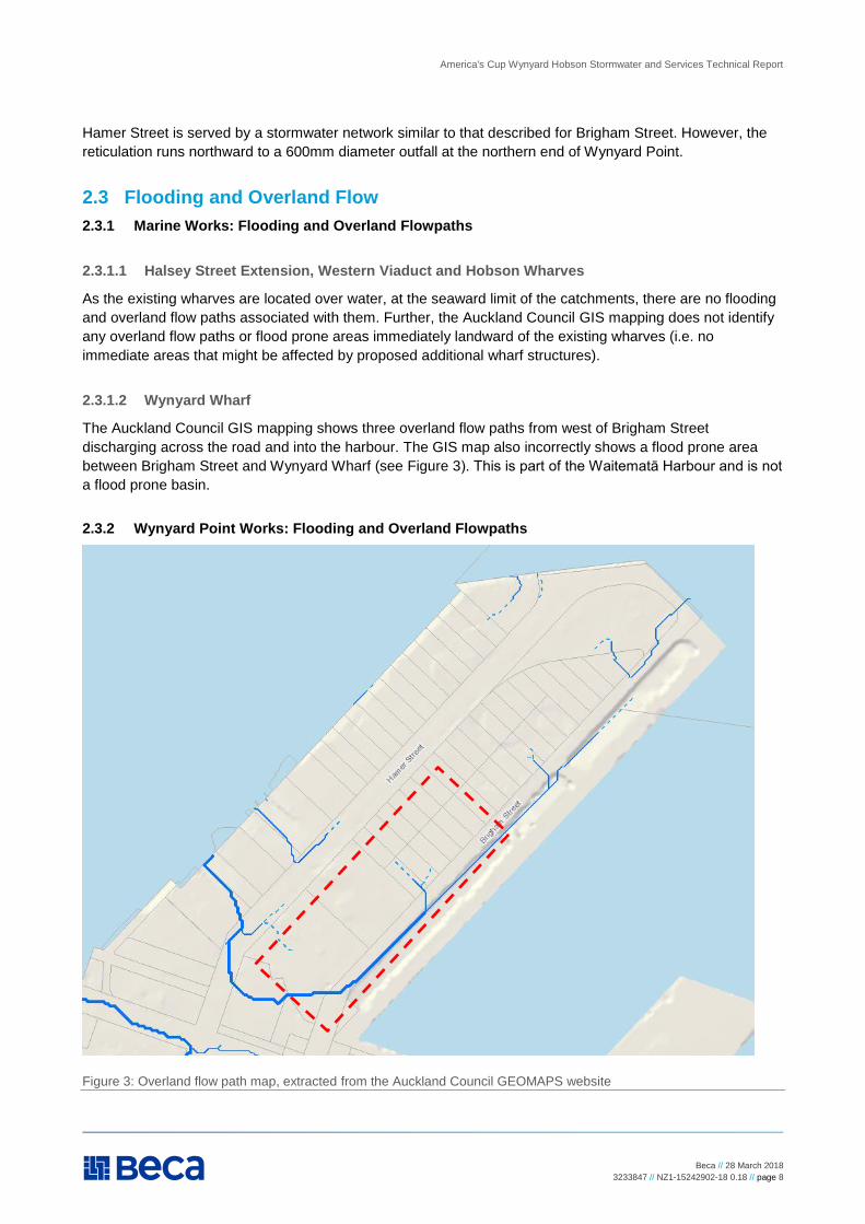
2.3.1.2 Wynyard Wharf
The Auckland Council GIS mapping shows three overland flow paths from west of Brigham Street
discharging across the road and into the harbour. The GIS map also incorrectly shows a flood prone area
between Brigham Street and Wynyard Wharf (see Figure 3). This is part of the Waitematā Harbour and is not
a flood prone basin.
2.3.2 Wynyard Point Works: Flooding and Overland Flowpaths
Figure 3: Overland flow path map, extracted from the Auckland Council GEOMAPS website

America's Cup Wynyard Hobson Stormwater and Services Technical Report
Beca // 28 March 2018
3233847 // NZ1-15242902-18 0.18 // page 9
2.3.2.1 Wynyard Point Landside Development Site
There are no flood prone areas or floodplains shown in the Auckland Council GIS map for the proposed
Wynyard Point site. Overland flow typically discharges via vehicular entrances into Hamer and Brigham
Street. This is reflected on the Auckland Council GIS map (Figure 3) which shows an overland flow path from
the ASB carpark into Brigham Street and from the BST site into both Hamer and Brigham Streets. The paved
sites adjoining the proposed syndicate bases (Stolthaven North tank farms and Wynyard Quarter) have
independent stormwater drainage which does not flow through the proposed site (outlined red).
2.3.2.2 Brigham and Hamer Streets
The Auckland Council GIS mapping shows three overland flow paths from west of Brigham Street
discharging across the road and into the harbour. The GIS map also shows an overland flowpath leading
from the BST tank farm into Hamer Street and a short section of overland flow on the western side of Hamer
Street between the entrances of the concrete batching plant and the adjacent Sanford yard.
2.4 Industrial Trade Activity (ITA) Management
2.4.1 Marine Works: Industrial and Trade Activities
2.4.1.1 Halsey Street Extension, Western Viaduct and Hobson Wharves: Industrial and Trade
Activities
The existing Halsey Street Extension, New Western Viaduct and Hobson Wharves are used for public
access, fishing vessel and general commercial wharfage. It is understood that they do not presently have
specific ITA management measures.
2.4.1.2 Wynyard Wharf: Industrial and Trade Activities
Present operations on Wynyard Wharf include:
Bulk liquids berths at the northern end of the wharf, associated with the BST and Stolthaven tank farms.
Layover use for a range of vessels (e.g. superyachts, bunker).
A seaplane berth and the Sealink vehicular ferry operation at the southern end of the wharf.
2.4.2 Wynyard Point Works: Industrial and Trade Activities
The existing ASB carpark and Panuku yard area are used for car parking and informal storage. It is
understood that they do not presently require specific ITA management measures.
The Stolthaven South and BST tank farm sites are currently used for bulk liquid storage operations. The bulk
liquid activities on the sites will be ceased and the site will be cleared of all operational tanks and pipelines
prior to occupation of the site for the construction of America’s Cup syndicate bases and infrastructure.
Management of the existing ITA activities are independent from the America’s Cup project and is therefore
not addressed here.
2.5 Existing Services
This section describes the existing land-based services. Drawings of the existing services are included in the
Existing Services Drawings 1 to 7. All services on the wharves are carried in ducts / flexible pipe suspended
on hangers beneath the wharves.
America's Cup Wynyard Hobson Stormwater and Services Technical Report
Beca // 28 March 2018
3233847 // NZ1-15242902-18 0.18 // page 10
2.5.1 Water Supply
2.5.1.1 Marine Works: Water Supply
Halsey Street Extension and Western Viaduct Wharves: 250mm dia and 150mm dia watermains are
located on the south and north sides, respectively, of Jellicoe St. Three (less than 10 year old) lines
extend onto the Halsey Street Extension Wharf. These include a 200mm dia watermain currently
supplying the Viaduct Events Centre, which is sprinklered.
Hobson Wharf: There is an existing private 100mm dia ring main on Hobson Wharf, serving the Maritime
Museum, which connects to a 150mm dia watermain at the landward end of Hobson Wharf, and then to
the public 250mm dia watermain in Quay St.
Wynyard Wharf: Two lines (250mm dia firefighting supply and “domestic” supply) cross Brigham St onto
Wynyard Wharf at the central bridging structure. There is an additional 100mm domestic supply line that
crosses Brigham St at the southern end of the wharf.
At the northern end of Wynyard Wharf there is a ‘foam’ pipeline which can be used by Fire and Emergency
New Zealand (FENZ) to suppress under-wharf fires.
2.5.1.2 Wynyard Point Works: Water Supply
Hamer Street: A 250mm dia water pipeline runs along the berm on the eastern side of Hamer Street. Two
existing 100mm dia lines lead off the main and into the Panuku yard and ASB carpark.
Brigham Street: A 250mm dia / 225mm dia water pipeline runs along the berm on the western side of
Brigham Street. Five existing 100mm dia lines lead off the main and into the proposed site at various
locations.
The berm on the western side of Brigham Street will be regraded to facilitate vehicle / vessel crossing
between Wynyard Wharf and the syndicate bases. The existing water infrastructure will need to be
modified/diverted to support this.
2.5.2 Wastewater
The existing wastewater reticulation proximate to the proposed development sites is laid out in the following
sections.
All the below wastewater lines ultimately connect to the new Wynyard Quarter pump station (corner of
Daldy/Pakenham Streets), which is presently under construction.
2.5.2.1 Marine Works: Wastewater
Hobson Wharf: A private rising main serving the Maritime Museum connects to the public system at a
manhole in Quay Street.
Halsey Street Extension and Western Viaduct Wharves: Two wastewater lines, 225mm dia and 250mm
dia, run northwards along Halsey Street to manholes at the corner where Jellicoe Street meets Halsey
Street. One line then continues northwards onto the wharf, serving the Viaduct Events Centre.
Wynyard Wharf: Wastewater connections lead from the Wynyard Wharf connecting to a 225mm dia
wastewater pipe on Brigham Street.
2.5.2.2 Wynyard Point Works: Wastewater
Hamer Street: Two 225mm dia wastewater pipes run along Hamer Street, one on each side. The pipe on
the eastern side of the road terminates at a manhole midway long the ASB carpark frontage. There is
America's Cup Wynyard Hobson Stormwater and Services Technical Report
Beca // 28 March 2018
3233847 // NZ1-15242902-18 0.18 // page 11
also a manhole adjacent to the boundary of the Stolthaven South and Panuku yard. The two wastewater
pipes appear to combine at a manhole adjacent to the south western corner of the BST site.
Brigham Street: A 225mm dia wastewater pipe runs along the western side of Brigham Street, serving the
adjacent buildings. It connects to a manhole at the southern end of Brigham Street midway along the BST
site frontage. There is an additional manhole at the southern end of Brigham Street connected to a
225mm dia wastewater pipe that was provided to support future development on Wynyard Point.
The berm on the western side of Brigham Street will be regraded to facilitate vehicle / vessel crossing
between Wynyard Wharf and the syndicate bases. The existing wastewater infrastructure will need to be
modified/diverted to support this.
2.5.3 Power
Existing power services are laid out in the following sections.
2.5.3.1 Marine Works: Power
Halsey Street Extension and Western Viaduct Wharves: There is an 11kV substation located at the
Viaduct Events Centre on Halsey Street Extension Wharf. This is connected by an 11kV line to a 22kV
substation at the Park Hyatt Hotel site, on the corner of Jellicoe and Halsey Streets. The 22kV substation
is currently being relocated further south along Halsey Street as part of the hotel construction.
Hobson Wharf: There is an 11kV substation on Hobson Wharf, which is understood to provide power to
the Maritime Museum.
Wynyard Wharf: There is an 11kV substation at the southern end of Wynyard Wharf which supplies the
existing ferry facilities.
2.5.3.2 Wynyard Point Works: Power
Hamer Street: There is an existing 11kV substation within the proposed site which is located on the
western side of the Panuku yard opposite the Firth concrete batching plant. There is another 11kV
substation on the western side of the road at 28 Hamer Street. Overhead 400V lines supply power to the
proposed site and other properties along Hamer Street.
Brigham Street: There is an 11kV substation at the southern end of Wynyard Wharf which supplies the
existing ferry facilities. A new 22kV substation is being installed on the south side of Jellicoe Street,
between Hamer and Brigham Streets. An overhead 400V power line on the western side of Brigham
Street supplies power to Bases C-G and other local properties.
There are a variety of existing private, above and below ground, electrical supply lines that serve the
existing facilities and lighting on Bases C-G.
To facilitate vehicular/vessel access from Brigham Street into the land site yards, it is anticipated that the
existing overhead line, and associated poles, located in the berm on the western side of Brigham Street will
need to be undergrounded in new ducting. Overhead lines in Hamer Street may also be undergrounded as
part of the street upgrade works and to support new vehicular crossings.
2.5.4 Communications
A number of existing telecommunication providers including Spark/Chorus Communications, Vector
Communications and Vodafone Communications, all provide services in Wynyard Quarter.
2.5.4.1 Marine Works: Communications
America's Cup Wynyard Hobson Stormwater and Services Technical Report
Beca // 28 March 2018
3233847 // NZ1-15242902-18 0.18 // page 12
Halsey Street Extension and Western Viaduct Wharves: Telecom ducts run along both sides of Halsey
Street and onto Halsey Street Extension Wharf, serving the Viaduct Events Centre. The ducting continues
to the end of the Western Viaduct Wharf.
Hobson Wharf: Multiple telecom ducts run along Quay Street and Hobson Street, passing onto Hobson
Wharf via under-wharf ducting to serve the Maritime Museum and the Outer Viaduct Harbour berths (the
telecom ducts extend to the end of the wharf).
Wynyard Wharf: Telecom ducting is bracketed to the western side of the wharf.
2.5.4.2 Wynyard Point Works: Communications
Hamer Street: Telecom ducting passes from Beaumont Street onto Hamer Street to serve the proposed
site and other local properties. Ducting runs along the west side of Hamer Street.
Brigham Street: Telecom ducts run along the berm on the western side of Brigham St, from Jellicoe St,
passing onto Wynyard Wharf at the curve in Brigham St adjacent to the ferry facilities.
It is anticipated that the berm on the western side of Brigham Street will need to be regraded to facilitate
vehicle / vessel crossing between Wynyard Wharf and the syndicate bases. Modifications or protection of
existing communication infrastructure may be required to support this.
2.5.5 Storage Tanks and Product Lines
There are a number of existing bulk liquid storage tanks located within the vicinity, both on the proposed site
and on adjacent land. There is also a variety of live and disused product pipelines leading to Wynyard Wharf
from adjacent tank farm sites.
Pipelines leading from the BST site, which is located to the south of the proposed development, cross
beneath Brigham Street onto a pipe bridge connected to Wynyard Wharf (i.e. over the harbour). The pipes
then run north beneath the wharf to the liquid bulk loading area. There are two over-road pipe bridges in the
area, one at the northern end of Brigham Street, and one at the northern end of Hamer Street.
Pipelines from the Stolthaven south site cross the road at 36 Brigham Street, then run along the seawall prior
to crossing onto Wynyard Wharf via an additional over-water pipe bridge. There is an additional over-road
pipe bridge leading from the Stolthaven North site, located to the north of the proposed development that
spans across Brigham Street and over the harbour onto Wynyard Wharf.
As noted in Section 2.4.2 the existing Stolthaven South and BST tanks, and associated pipelines, will be
removed by the leaseholder prior to construction.
Disused underground product lines are located throughout Wynyard Quarter, a legacy of the historic bulk
liquids use. Around Halsey and Jellicoe Streets, many of these have been removed during streetscape and
site development works since 2008. However the brownfields sites and road corridors on Wynyard Point are
still expected to contain a number of old lines.
America's Cup Wynyard Hobson Stormwater and Services Technical Report
Beca // 28 March 2018
3233847 // NZ1-15242902-18 0.18 // page 13
3 Proposed Stormwater, ITA & HS Management
3.1 ITA Categories
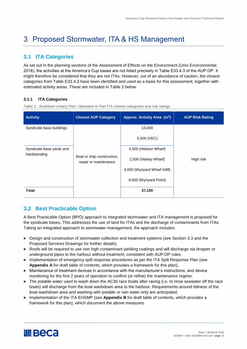
As set out in the planning sections of the Assessment of Effects on the Environment (Unio Environmental,
2018), the activities at the America’s Cup bases are not listed precisely in Table E33.4.3 of the AUP:OP. It
might therefore be considered that they are not ITAs. However, out of an abundance of caution, the closest
categories from Table E33.4.3 have been identified and used as a basis for this assessment, together with
estimated activity areas. These are included in Table 2 below.
3.1.1 ITA Categories
Table 2 : Auckland Unitary Plan: Operative in Part ITA closest categories and risk ratings
Activity Closest AUP Category Approx. Activity Area (m2) AUP Risk Rating
Syndicate base buildings
Boat or ship construction,
repair or maintenance
13,000
5,000 (VEC)
High risk
Syndicate base yards and
hardstanding
4,500 (Hobson Wharf)
2,000 (Halsey Wharf)
4,000 (Wynyard Wharf Infill)
8,600 (Wynyard Point)
Total 37,100
3.2 Best Practicable Option
A Best Practicable Option (BPO) approach to integrated stormwater and ITA management is proposed for
the syndicate bases. This addresses the use of land for ITAs and the discharge of contaminants from ITAs.
Taking an integrated approach to stormwater management, the approach includes:
Design and construction of stormwater collection and treatment systems (see Section 3.3 and the
Proposed Services Drawings for further details).
Roofs will be required to use non high contaminant yielding coatings and will discharge via dropper or
underground pipes to the harbour without treatment, consistent with AUP:OP rules.
Implementation of emergency spill response procedures as per the ITA Spill Response Plan (see
Appendix A for draft table of contents, which provides a framework for this plan).
Maintenance of treatment devices in accordance with the manufacturer’s instructions, and device
monitoring for the first 2 years of operation to confirm (or refine) the maintenance regime.
The potable water used to wash down the AC36 race boats after racing (i.e. to rinse seawater off the race
boats) will discharge from the boat washdown area to the harbour. Requirements around tidiness of the
boat washdown area and washing with potable or rain water only are anticipated.
Implementation of the ITA EHSMP (see Appendix B for draft table of contents, which provides a
framework for this plan), which document the above measures.
America's Cup Wynyard Hobson Stormwater and Services Technical Report
Beca // 28 March 2018
3233847 // NZ1-15242902-18 0.18 // page 14
3.3 Stormwater Reticulation and Treatment
The proposed concepts for stormwater reticulation and treatment devices have been developed in
accordance with the following:
AUP: OP.
Auckland Regional Plan: Coastal.
Auckland Regional Council Technical Publication 108: Guidelines for Stormwater Runoff Modelling in the
Auckland Region.
Auckland Regional Council Technical Publication 10: Stormwater management devices design guideline
manual.
Auckland Code of Practice for Development and Subdivision, Chapter 4: Stormwater.
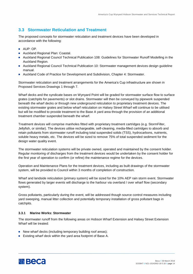
Stormwater reticulation and treatment arrangements for the America’s Cup infrastructure are shown in
Proposed Services Drawings 1 through 7.
Wharf decks and the syndicate bases on Wynyard Point will be graded for stormwater surface flow to surface
grates (catchpits for pavements) or slot drains. Stormwater will then be conveyed by pipework suspended
beneath the wharf decks or through new underground reticulation to proprietary treatment devices. The
existing stormwater grates and below wharf reticulation on Halsey Street Wharf will continue to be utilised
but will be modified to provide treatment to the Base A yard area through the provision of an additional
treatment chamber suspended beneath the wharf.
Treatment devices will comprise manholes fitted with proprietary treatment cartridges (e.g. StormFilter,
Jellyfish, or similar). The devices utilise rechargeable, self-cleaning, media-filled cartridges to absorb and
retain pollutants from stormwater runoff including total suspended solids (TSS), hydrocarbons, nutrients,
soluble heavy metals, etc. The devices will be sized to remove 75% of total suspended sediment for the
design water quality event.
The stormwater reticulation systems will be private owned, operated and maintained by the consent holder.
Regular monitoring of discharges from the treatment devices would be undertaken by the consent holder for
the first year of operation to confirm (or refine) the maintenance regime for the devices.
Operation and Maintenance Plans for the treatment devices, including as built drawings of the stormwater
system, will be provided to Council within 3 months of completion of construction.
Wharf and landside reticulation (primary system) will be sized for the 10% AEP rain storm event. Stormwater
flows generated by larger events will discharge to the harbour via overland / over wharf flow (secondary
system).
Gross pollutants, particularly during the event, will be addressed though source control measures including
yard sweeping, manual litter collection and potentially temporary installation of gross pollutant bags in
catchpits.
3.3.1 Marine Works: Stormwater
The stormwater runoff from the following areas on Hobson Wharf Extension and Halsey Street Extension
Wharf will be treated:
New wharf decks (including temporary building roof areas);
Existing wharf deck within the yard area footprint of Base A.
America's Cup Wynyard Hobson Stormwater and Services Technical Report
Beca // 28 March 2018
3233847 // NZ1-15242902-18 0.18 // page 15
Runoff from the new pedestrian-only breakwaters and the breakwater trunk on Halsey Street extension
wharf, which will only be subject to occasional low frequency vehicle traffic (vehicle turning), will not be
subject to treatment and will discharge directly into the harbour.
The treatment devices would be expected to be installed in offline mode and would be accessible from the
wharf deck for maintenance. The wharves will be divided into maximum 3,000m2 catchments to limit the size
of individual treatment devices suspended beneath the decks. Example calculations of the number of
cartridges needed for this catchment size and a typical drawing of a StormFilter manhole vault are included
in Appendix C. The calculations give a total of 6 cartridges per device for the catchment area based on:
Catchment area of 3,000m2.
The water quality rainfall intensity of 10mm/hr.
Run-off coefficient of 1.0.
A design water quality flow of approximately 9l/s.
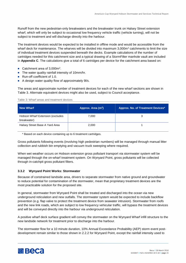
The areas and approximate number of treatment devices for each of the new wharf sections are shown in
Table 3. Alternate equivalent devices might also be used, subject to Council acceptance.
Table 3: Wharf areas and treatment devices
New Wharf Approx. Area (m2) Approx. No. of Treatment Devices*
Hobson Wharf Extension (excludes
breakwater)
7,000 3
Halsey Street Base A Yard Area 2,000 1
* Based on each device containing up to 6 treatment cartridges.
Gross pollutants following events (involving high pedestrian numbers) will be managed through manual litter
collection and rubbish bin emptying and vacuum truck sweeping where required.
When wet weather occurs on Hobson extension gross pollutant transport via stormwater system will be
managed through the on-wharf treatment system. On Wynyard Point, gross pollutants will be collected
through in-catchpit gross pollutant filters.
3.3.2 Wynyard Point Works: Stormwater
Because of constrained landside area, drivers to separate stormwater from native ground and groundwater
to reduce potential for contamination of the stormwater, mean that proprietary treatment devices are the
most practicable solution for the proposed site.
In general, stormwater from Wynyard Point shall be treated and discharged into the ocean via new
underground reticulation and new outfalls. The stormwater system would be expected to include backflow
prevention (e.g. flap valve to protect the treatment device from seawater intrusion). Stormwater from roofs
and the new link roads, which are subject to low frequency vehicular traffic, will bypass the treatment devices
and will be conveyed directly into the harbour via underground reticulation.
A positive wharf deck surface gradient will convey the stormwater on the Wynyard Wharf infill structure to the
new landside network for treatment prior to discharge into the harbour.
The stormwater flow for a 10 minute duration, 10% Annual Exceedance Probability (AEP) storm event post-
development remain similar to those shown in 2.2.2 for Wynyard Point, except the rainfall intensity used to
America's Cup Wynyard Hobson Stormwater and Services Technical Report
Beca // 28 March 2018
3233847 // NZ1-15242902-18 0.18 // page 16
calculate the flow will increase to 17.5mm/10 min to account for the effects of climate change resulting in a
peak stormwater flow of 0.667m3/s. Wynyard Wharf extension/infill will also contribute an additional 0.11m3/s
to this peak stormwater flow, creating an overall combined peak flow of 0.777m3/s.
It is anticipated that three new stormwater outfalls will be required, each with a diameter of approximately
0.525m.
To limit the depth of stormwater reticulation pipes, it is assumed that the total combined catchment (of
approx. 12,600m2) will discharge via three separate outfalls each served by a separate treatment chamber.
Example calculations of the number of cartridges required for the individual catchments and a typical drawing
of a StormFilter manhole vault are included in Appendix C. The calculations give a total of 28 cartridges for
the catchment area based on:
Total catchment area of approximately 12,600m2 (see Table 4).
The water quality rainfall intensity of 10mm/hr.
Run-off coefficient of 1.0.
A total design water quality flow of approximately 37 l/s (split between three treatment devices).
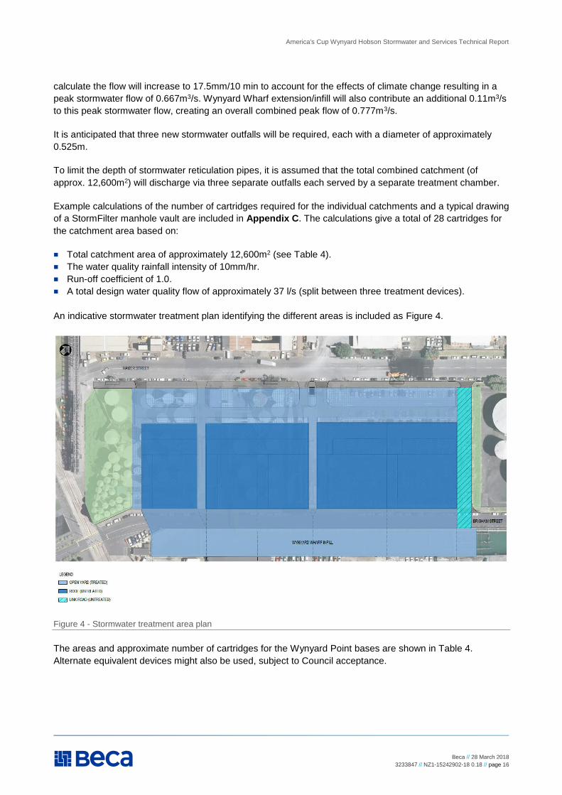
An indicative stormwater treatment plan identifying the different areas is included as Figure 4.
Figure 4 - Stormwater treatment area plan
The areas and approximate number of cartridges for the Wynyard Point bases are shown in Table 4.
Alternate equivalent devices might also be used, subject to Council acceptance.
America's Cup Wynyard Hobson Stormwater and Services Technical Report
Beca // 28 March 2018
3233847 // NZ1-15242902-18 0.18 // page 17
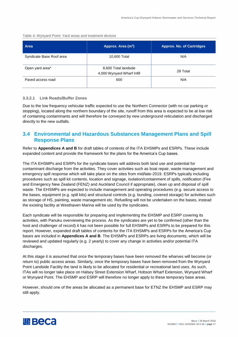
Table 4: Wynyard Point: Yard areas and treatment devices
Area Approx. Area (m2) Approx. No. of Cartridges
Syndicate Base Roof area 10,600 Total N/A
Open yard area* 8,600 Total landside
4,000 Wynyard Wharf Infill 28 Total
Paved access road 600 N/A
3.3.2.1 Link Roads/Buffer Zones
Due to the low frequency vehicular traffic expected to use the Northern Connector (with no car parking or
stopping), located along the northern boundary of the site, runoff from this area is expected to be at low risk
of containing contaminants and will therefore be conveyed by new underground reticulation and discharged
directly to the new outfalls.
3.4 Environmental and Hazardous Substances Management Plans and Spill Response Plans
Refer to Appendices A and B for draft tables of contents of the ITA EHSMPs and ESRPs. These include
expanded content and provide the framework for the plans for the America’s Cup bases.
The ITA EHSMPs and ESRPs for the syndicate bases will address both land use and potential for
contaminant discharge from the activities. They cover activities such as boat repair, waste management and
emergency spill response which will take place on the sites from mid/late-2019. ESRPs typically including
procedures such as spill kit contents, location and signage, isolation/containment of spills, notification (Fire
and Emergency New Zealand (FENZ) and Auckland Council if appropriate), clean up and disposal of spill
waste. The EHSMPs are expected to include management and operating procedures (e.g. secure access to
the bases, equipment (e.g. spill kits) and structural controls (e.g. bunding, covered storage) for activities such
as storage of HS, painting, waste management etc. Refuelling will not be undertaken on the bases, instead
the existing facility at Westhaven Marina will be used by the syndicates.
Each syndicate will be responsible for preparing and implementing the EHSMP and ESRP covering its
activities, with Panuku overviewing the process. As the syndicates are yet to be confirmed (other than the
host and challenger of record) it has not been possible for full EHSMPs and ESRPs to be prepared for this
report. However, expanded draft tables of contents for the ITA EHSMPs and ESRPs for the America’s Cup
bases are included in Appendices A and B. The EHSMPs and ESRPs are living documents, which will be
reviewed and updated regularly (e.g. 2 yearly) to cover any change in activities and/or potential ITA
discharges.
At this stage it is assumed that once the temporary bases have been removed the wharves will become (or
return to) public access areas. Similarly, once the temporary bases have been removed from the Wynyard
Point Landside Facility the land is likely to be allocated for residential or recreational land uses. As such,
ITAs will no longer take place on Halsey Street Extension Wharf, Hobson Wharf Extension, Wynyard Wharf
or Wynyard Point. The EHSMP and ESRP will therefore no longer apply to these temporary base areas.
However, should one of the areas be allocated as a permanent base for ETNZ the EHSMP and ESRP may
still apply.
America's Cup Wynyard Hobson Stormwater and Services Technical Report
Beca // 28 March 2018
3233847 // NZ1-15242902-18 0.18 // page 18
3.5 Hazardous Substances
ETNZ has advised that the following approximate quantities and types of HS will be stored on each syndicate
base, to be used for boat repairs:
Acetone (250 litres)
Paint (nominal 100 litres)
Epoxy (nominal 100 litres)
Thinners (nominal 20 litres).
These are Class 3 Flammable Liquids.
The HS will be stored in either a Dangerous Goods (DG) store that complies with NZ regulations or 1-2
proprietary NZ-compliant DG cabinets. The store/cabinets have built in bunds and will be contained in
roofed, well ventilated areas of the syndicate buildings. They will be surrounded by an exclusion and safe
working zone where ignition sources, smoking etc. will not be permitted. Signage will be required at the store
and entrance to the area. Two fire extinguishers will be required.
There will be no outlet to stormwater or trade waste from the DG store. 250l spill kits appropriate for
flammable substances will be kept on site. Any spills will be managed as per the syndicate base ESRPs, as
indicated above. Hazardous Substance Location certification (from a compliance certifier) is required for the
site/s if the actual stored quantities are above 100L of class 3.1B (Acetone), as indicated above. A training
plan covering management practices and emergency spill response procedures will be prepared and
implemented for syndicate personnel working on the base. The measures above will be documented by each
syndicate in the EHSMPs.
Separately, the Construction EHSMP will include a management plan if any HS are to be used on site during
construction (refer to the America’s Cup – Wynyard Hobson - Base Infrastructure Technical Report).
America's Cup Wynyard Hobson Stormwater and Services Technical Report
Beca // 28 March 2018
3233847 // NZ1-15242902-18 0.18 // page 19
4 Proposed Services
The proposed syndicate bases will be supplied with lighting, power, water, wastewater and telecom (fibre
optic) services. An overview of the approximate demand and infrastructure required is provided in this
section.
As a general approach, the marine works services will be connected to the existing landside reticulation
independent of existing wharf-based services to avoid interference with existing facilities (e.g. Maritime
Museum). Services provided will be suspended beneath the new and existing wharf decks. Construction of
initial below-ground ducting and pipelines will be required to extend the existing land-based services. It is
however anticipated that Base A will primarily utilise existing services that serve the VEC. The proposed
services will be private lines owned, operated and maintained by the consent holder.
The majority of services on Wynyard Point will be connected to existing services networks in Hamer and
Brigham Streets. As for the marine works services, the new services will be private lines owned, operated
and maintained by the consent holder.
Concept drawings showing the layout of proposed services are presented in the Marine and Wynyard Point
Works Proposed Services Drawings. The layouts and connection points shown are indicative only, subject to
detailed design and agreement with the relevant services organisations.
4.1 Water Supply
4.1.1 Water Supply General
Water supply will be provided to all syndicate bases for potable and boat washdown water and firefighting.
The supply will terminate at the boundary of each base with a valve and meter.
Concept calculations have been carried out to give indicative and approximate order of magnitude of water
demand quantities, with the results as follows:
Potable water for syndicate bases 6,250 Litres per day per base (based on 100 personnel/base)
Potable water for superyachts 30,000 Litres per day (based on 30 superyachts with an average
vessel length of 50m, and crew of 10 as per PIANC, 20131)
Water for washdown of race boats 50,000 Litres per day
FENZ has recommended that the syndicate buildings be sprinklered because of the nature of carbon fibre
fires (the race boats largely consist of carbon fibre). The sprinkler systems will be connected to the local
water supply (refer below). Water supply for active firefighting on the wharves using FENZ appliances is
expected to be sourced predominantly from the potable water system (approximately 25 litres per second
demand). Due to the presence of potentially significant amounts of carbon fibre, it is anticipated that the
sprinkler system shall have a water demand in the order of 80 litres per second, providing carbon fibre etc.
shall not be stored to heights greater than 1.2m. If the storage height exceeds 1.2m, a more significant water
demand for the sprinkler system is required.
1 Report 134, 2013, Design and Operational Guidelines for Superyacht Facilities, Permanent International
Association of Navigation Congresses (PIANC)
America's Cup Wynyard Hobson Stormwater and Services Technical Report
Beca // 28 March 2018
3233847 // NZ1-15242902-18 0.18 // page 20
Appendix D includes further detail regarding firefighting provisions and includes minutes of the meeting with
FENZ to discuss the proposed development.
4.1.2 Marine Works: Water Supply
On Halsey Street Extension Wharf, the existing watermain is anticipated to supply the sprinkler system and
hydrants on the wharf. A single watermain will supply the Hobson Wharf extension (hydrants and sprinkler
system), which accommodates a single base only. The water supply line on Wynyard Wharf is expected to
connect to the public watermain in Brigham Street and will feed sprinkler systems and wharf hydrants.
Permanent dry standpipes utilising water intake directly from the ocean may also be utilised subject to FENZ
approval.
It is expected that connection points for the water supply to the wharves will be as follows:
Halsey Street Extension Wharf: existing hydrants to be utilised or connection to the existing 200mm dia
watermain which currently provides for the VEC.
Hobson Wharf: connection to either the existing underwharf 125mm dia watermain beneath the Harbour
Entrance Protection Wharf, or the 150mm dia or 250mm dia public watermains on Quay Street if
connection to the underwharf watermain is not feasible.
Wynyard Wharf: connection to either the 225mm dia watermain at the south end of Brigham Street,
and/or the 250mm dia watermain north of the bases on Wynyard Wharf.
4.1.3 Wynyard Point Works: Water Supply
A single watermain will supply each of the bases (hydrants and sprinkler system).
The existing 225mm dia water main in Brigham Street will be diverted, along the base frontage, to facilitate
the berm regrading and to accommodate the base foundations. New underground reticulation pipelines will
connect into the diverted water main to provide water supply to the Wynyard Point bases. Flow capacity and
pressure testing of the watermain will be undertaken as part of the project detailed design.
4.2 Wastewater
4.2.1 Wastewater General
Wastewater connections are to be provided to all syndicate bases for drainage from sanitary facilities and
boatshed floors.
Concept calculations have been carried out to give indicative and approximate order of magnitude
wastewater generation quantities, with the results as follows:
Wastewater generated by syndicate bases 6,250 Litres per day per base (based on 100
personnel/base)
Wastewater generated by superyachts 75,000 Litres per day (based on 30 superyachts with an
average vessel length of 50m, and crew of 10 as per
PIANC, 2013)
4.2.2 Marine Works: Wastewater
A pumpout facility will also be provided for superyachts berthed on Halsey Street Extension Wharf (west),
similar to the vacuum pump out system installed in the Outer Viaduct Harbour for the 2000 America’s Cup.
Connection points for these lines are expected to be:
America's Cup Wynyard Hobson Stormwater and Services Technical Report
Beca // 28 March 2018
3233847 // NZ1-15242902-18 0.18 // page 21
Halsey Street Extension Wharf: existing wastewater system serving the VEC to be utilised.
Hobson Wharf: the existing manhole on the north side of Quay St.
Wynyard Wharf: the existing manhole at the south end of Brigham Street / north end of Daldy Street,
adjacent to the existing ferry facilities.
4.2.3 Wynyard Point Works: Wastewater
The existing 225mm dia waste water line in Brigham Street will be diverted, along the base frontage, to
facilitate the berm regrading and to accommodate the base foundations. This will require the construction of
several new manholes. Gravity lines from each base will be connected directly to the diverted line or new
manholes. Preliminary assessment indicates that this pipeline has sufficient capacity but a detailed flow
capacity assessment will be undertaken during detailed design. If there is insufficient capacity, then on-site
storage will be provided.
4.3 Power
4.3.1 Power General
It is understood that at previous events, mobile generators significantly supplemented electrical provision to
the bases to avoid over-utilising the existing land-based infrastructure and safeguard the syndicates from any
power outages. It is anticipated that a similar approach may be taken for the syndicate bases in event mode.
4.3.2 Marine Works: Power
During non-event operation (Business-as-Usual, BAU) power will be provided to each syndicate base, via
individual power pedestals, and also to the new lighting infrastructure. Cables will be protected by ducts
suspended beneath the wharf decks.
Anticipated connection points for the new facilities are:
Halsey Street Extension Wharf: the base buildings and yard areas will be serviced by the existing network
serving the VEC surrounding wharf areas. Connections to the existing 22kV substation, which is currently
being relocated south along Halsey Street from the Park Hyatt Hotel site will be provided to accommodate
superyacht vessel berthing along the western side of the wharf.
Hobson Wharf: the existing 11kV substation on Hobson Wharf;
Wynyard Wharf: the 22kV substation which is being installed on the south side of Jellicoe St, between
Hamer and Brigham Streets.
4.3.3 Wynyard Point Works: Power
New underground ducting will be provided to accommodate power cables and facilitate connection to the
existing network.
Anticipated connection points for the new facilities are:
The existing 11kV substation which is located within the proposed site, on the western side between
Bases E and D.
The 22kV substation which is being installed on the south side of Jellicoe St, between Hamer and
Brigham Streets.
America's Cup Wynyard Hobson Stormwater and Services Technical Report
Beca // 28 March 2018
3233847 // NZ1-15242902-18 0.18 // page 22
As noted in section 2.5.3.2, to facilitate vehicular/vessel access from Brigham Street into the land site yards,
it is anticipated that the existing overhead line, and associated poles, located in the berm on the western side
of Brigham Street will need to be undergrounded in new ducting.
It is currently assumed that the existing substation C-236, adjacent to the SeaLink ferry terminal, will remain
in place. However, should the substation be decommissioned and removed as a result of the commissioning
of the new 22kVa substation on Jellicoe Street, the yard boundary for Base G can be amended to become
the full width of the building, as shown in the Wynyard Point Works Civil Drawings.
4.4 Lighting
4.4.1 BAU Lighting
Lighting poles with streetlight luminaires (zero tilt), at a height of approximately 8m will be situated along the
Hobson Wharf Extension at a spacing to provide a safe illumination level, similar to the existing lighting on
Halsey Street Extension, Western Viaduct and Hobson Wharves. Zero tilt luminaires are oriented parallel to
the ground, with all light projected below the horizontal plane.
The approach to provision of lighting to the Syndicate Bases will be similar to the above, and similar to the
existing lighting in the ASB carpark. Consideration of mounting zero tilt lights on the Base buildings would be
of benefit. Existing street lights and poles on Hamer and Brigham Streets will be removed as required to
facilitate construction, and replaced.
The new lighting will be designed in accordance with Crime Prevention Through Environmental Design
(CPTED) principles and consistent with E24.6.1 General Standards in the AUP:OP – Rules as applicable
(Lighting Category 2 Low brightness for the Coastal Marine Zone). Power will be supplied by underwharf
cables and underground ducting as noted above.
Navigational lighting is addressed in America’s Cup Wynyard Hobson Navigational Safety and Utility
(Navigatus, 2018).
4.4.2 Construction Lighting
Construction lighting is covered in the America's Cup Wynyard Hobson Base Infrastructure Technical Report
(Beca, 2018).
4.4.3 Event Lighting
The event details are yet to be fully developed at this stage of the project. However it is assumed that the
America’s Cup event lighting will be similar in principle to that of the 2018 Volvo Ocean Stop Over, except
that unlike the Volvo event the America’s Cup operation will, in the main, be during daylight hours. It is
expected that America’s Cup entertainment events will take place during the hours of 7am - 10pm (pre-
curfew hours). Anticipated lighting arrangements are as follows:
Bases: It is assumed that event lighting will be as per BAU lighting because the main activity will be
during daylight hours and assuming any night activity will be inside the syndicate base buildings fitted with
blackout drapes (or with no/limited windows).
Primary entertainment areas (Eastern Viaduct, Te Wero Island, North Wharf, Jellicoe St carpark and Silo
Park): the existing lighting will be used but this may not cover the full extent of these areas sufficiently for
event activities, in terms of safety and security. Temporary lighting will therefore be installed in addition to
the existing lighting when event activities are taking place. The additional temporary pole-mounted
America's Cup Wynyard Hobson Stormwater and Services Technical Report
Beca // 28 March 2018
3233847 // NZ1-15242902-18 0.18 // page 23
luminaires will be mounted at heights between a minimum of 6m and a maximum of 10m. The actual
height will be determined during the design phase to ensure minimum number of poles for the coverage
areas. Zero tilt luminaires will be used.
Temporary feature lighting, big screens, and lighting for hospitality features are also expected to be
located in the primary entertainment areas, similar to the Volvo event. The temporary feature lighting (i.e.
all light may not necessarily be projected below the horizontal plane) is expected to be used at specific,
limited times during the event and also to have controlled beams, limiting light to the particular illuminated
feature/effect.
Television broadcast lighting may be used in outdoor public places from time to time during the event,
although the daytime nature of the racing means this will be limited.
The event lighting will be covered in a Lighting Management Plan as part of the Event Management Plan,
and will address the following:
Map of surrounding light sensitive areas.
All event lighting to comply with AUP:OP requirements for pre-curfew and curfew levels for spill light and
glare and general lighting planning rules. Spill light and glare standards to windows of habitable rooms of
lawfully established dwellings to be complied with.
Confirmation design is in accordance with CPTED principles and consistent with E24.6.1 General
Standards in the AUP:OP – Rules as applicable.
Layout and luminaire type of temporary lighting.
Location and orientation of big screens, feature lighting and lighting for hospitality features.
Outside broadcast area locations.
10pm shut down time for temporary additional event lighting.
4.5 Communications
Similarly to power supply, telecom and fibre optic connections will be provided to each syndicate base by
means of individual telecom pedestals. The expected connection points to the existing communications
system are:
Halsey Street Extension and Western Viaduct Wharves: utilisation of the existing communication network
serving the VEC or connection to the communications chamber at the landward end of Halsey Street
Extension Wharf for additional supply to support the superyacht berths.
Hobson Wharf: connection to the communications chamber at the landward end of Hobson Wharf.
Brigham Street and Wynyard Wharf: connection at the communications chamber towards the southern
end of Brigham Street.
Jellicoe and Hamer Street Intersection: connection to the existing communications chamber.
4.6 Storage Tanks and Product Lines
As part of the land transfer, Stolthaven and BST will be required to remove all of their assets including tanks,
foundations and product pipes located on, or leading from, the Stolthaven South and BST sites. This will
include the removal of the pipelines and associated pipe bridges leading to Wynyard Wharf.
America's Cup Wynyard Hobson Stormwater and Services Report
Beca // 28 March 2018
3233847 // NZ1-15242902-18 0.18 // page 24
5 Assessment of Effects on the Environment
5.1 Stormwater (and ITA)
5.1.1 Marine Works
No additional stormwater will be discharged into the harbour as a result of the proposed wharf structures.
Rainwater and atmospheric particulates will be deposited in the harbour regardless of their presence.
Vehicle traffic on the wharves will be limited during both the America’s Cup period and once the wharves
return to public use, hence only low levels of particulates (e.g. tyre particles) and hydrocarbons from
vehicles. The hard concrete surface of the wharves will also produce little sediment. There is therefore
minimal potential to generate discharge of suspended sediment in stormwater runoff from the proposed
wharves.
Activities with the potential to result in discharges via stormwater runoff will be managed by procedures set
out in the ITA EHSMP. For example, race boat maintenance will typically be undertaken under cover within
the syndicate buildings, minimising the potential for material to be mobilised in stormwater runoff. General
housekeeping matters such as site tidiness and waste management will be addressed by procedures in the
EHSMP. Boat washdown water, as described in Section 3.2, will be required to contain only potable (or rain)
water and harbour water from the boats. The quantity of boat washdown water (50m3/day on racing and
training days) is negligible (0.01%) compared with the volume of seawater exchanged in the water body on
each tide.
Modest quantities of HS used for boat maintenance (of the order of 100 – 250 litres per substance) will be
stored at the syndicate bases. This will be confined to the ETNZ base once the temporary bases are
removed. The ESRPs and the EHSMPs (refer to Appendices C and D) will set out storage requirements for
these substances e.g. DG store or cabinets, covered and self-bunded; labelled containers; handling/use
procedures, and actions to mitigate any discharge in the event of a spill. Management measures will also
include an exclusion/safe working zone around the DG store, where ignition sources will not be permitted.
In addition to the above, stormwater from the proposed wharf structures and Base A will be collected and
treated prior to discharge. The stormwater treatment devices will be designed to remove 75% of total
suspended sediment, in accordance with the AUP:OP. The treated stormwater will then be substantially
diluted by the daily tidal flows within the wider harbour. This is illustrated by comparison of the total
stormwater discharge from the proposed wharf extension for the 1% AEP 24 hour rainfall event (2,000m3)
with the daily volume of water exchanged in the Waitematā Harbour (160 million m3).
There will be negligible scour and erosion effects from the discharge, as the discharge points on the wharves
are in water depths of at least 3m and are seaward of the shoreline, which is also protected by hard seawall
structures.
There is no potential for flooding of, or damage or nuisance to, other properties because the sites are located
over the Waitematā Harbour (i.e. seaward of the downstream end of the Freemans Bay catchment) and do
not obstruct any existing overland flowpaths or floodplains. As noted in Section 3, the area between Brigham
Street and Wynyard Wharf is harbour waters and not a floodprone area, and is therefore not affected by the
development.
America's Cup Wynyard Hobson Stormwater and Services Report
Beca // 28 March 2018
3233847 // NZ1-15242902-18 0.18 // page 25
5.1.2 Wynyard Point Works
There will be no increase in impervious area as a result of the Wynyard Point works and there will be no
additional stormwater discharged into the public stormwater network or harbour.
Vehicle traffic on the site is anticipated to reduce as a result of the development as the ASB carpark (approx.
250 spaces) will be replaced by yards with limited vehicular traffic, hence a reduction on levels of particulates
(e.g. tyre particles) and hydrocarbons from vehicles. The hard paved surface of the yards and buildings will
also produce little sediment.
Activities with the potential to result in discharges via stormwater runoff will also be managed by procedures
set out in the ITA EHSMP. With the removal of the Stolthaven South and BST tank farms the quantity of HS
stored on the site will also be significantly reduced. Other HS associated with the syndicate bases will be
managed in the same way as for maritime works.
In addition to the above, stormwater from the proposed Wynyard Point yards will be collected and treated
prior to discharge. Therefore, the discharge of sediment from Wynyard Point into the harbour will be reduced
compared with the existing situation.
The potential for flooding of, or damage or nuisance to, other properties will also be reduced as a result of
the development because:
Actual flows remain small and the new stormwater drainage system will capture surface flow;
The sites are at the downstream end of the catchment;
Flows from the primary stormwater system will discharge directly into the harbour via underground
reticulation;
The Wynyard Point pavement will be graded so that flows in excess of the primary system capacity will
flow overland, into Hamer or Brigham Streets prior to discharging directly into the harbour;
There are no affected flood prone areas or floodplains; and
At low points (eastern edge of Brigham Street) overflow points will be provided directly to the harbour.
5.1.3 General
Any adverse effects of stormwater and ITA discharge via stormwater in terms of land use, discharge quantity
and quality, and of HS use, storage and disposal are considered to be less than minor based on the site
features and provided the measures described above are implemented.
The proposed Wynyard Point development has minor beneficial effects compared with the existing situation,
as there is a reduction in potential for sediment discharge, due to the proposed modern stormwater treatment
and car park removal and a reduction in the storage of HS with the removal of the Stolthaven South tank
farm and the BST tank farm.
It is also notable that these activities have taken place in the same general area during the 2000 and 2003
America’s Cup events, as well as the more recent events overseas. The procedures outlined in these
documents have incorporated the results of discussions with ETNZ, demonstrating a level of experience with
HS management practices within the syndicates.
5.2 Effects of Services (excluding Lighting)
The proposed connections and anticipated demands for the America’s Cup event infrastructure have been
discussed with the relevant services companies and stakeholders, as follows:
Water supply and wastewater: Watercare.
America's Cup Wynyard Hobson Stormwater and Services Report
Beca // 28 March 2018
3233847 // NZ1-15242902-18 0.18 // page 26
Power: Vector.
Communications: Chorus.
Firefighting: FENZ.
The services (utilities) companies are supportive of the America’s Cup event(s) and have indicated that in
principle there should be sufficient capacity (refer to correspondence in Appendix D). FENZ has had input to
the proposed services for firefighting purposes. The diversion of existing services will be undertaken in
discussion with the relevant service company to ensure disruption is minimised. The proposed connections
should have adequate capacity to accommodate the anticipated demands outlined in this report.
5.2.1 Marine Works
Connections to existing services for Halsey Wharf Extension and Wynyard Wharf (south) are likely to require
pipework to run across sections of Jellicoe St and Karanga Plaza that was upgraded some 7-15 years ago.
Construction of these connections has the potential to disrupt activities in these areas and affect the surface
finish. The potential disruption will be reduced by adopting measures such as combined services trenches (to
reduce the number of trenching operations), routing works as far as possible through existing access
roadways or other less sensitive/lower quality surface finishes rather than high quality finish public areas (to
reduce impacts on public access and existing landscaping finishes), directional drilling (where ground
conditions support this), temporary traffic management where connections cross live roads (refer to the
America’s Cup – Wynyard Hobson - Traffic and Transport Technical Report), and planning and coordinating
the works with adjacent businesses and with construction access requirements.
Any adverse effects of the proposed services are considered to be less than minor on the basis that the
measures described above are undertaken, particularly including planning and coordination of works,
temporary traffic management and methods such as combined trenches, directional drilling and routing of
works.
5.2.2 Wynyard Point Works
Brigham and Hamer Streets are in brownfields condition and serve the existing commercial developments,
bulk liquids storage sites, and ASB carpark. Planning and coordinating the works with the site operators and
with construction access requirements, standard trenching practices, and temporary traffic management will
be utilised to reduce impacts of the connection work on adjacent businesses and road users.
Any adverse effects of the proposed services are considered to be less than minor on the basis that the
measures described above are undertaken, particularly including planning and coordination of works,
temporary traffic management and methods such as combined trenches, directional drilling and routing of
works.
5.3 Lighting Effects
5.3.1.1 BAU Lighting
Sites potentially sensitive to lighting (e.g. apartments, hotels) are grouped to the east and south of Viaduct
Harbour, Pakenham Street, and 1.5km north on Stanley Point. The northern extent of Wynyard Point (i.e. the
bulk liquids storage and existing carpark area) are not sensitive sites. Other potential receptors are marine
users and motorists. In terms of the general context of the development, the majority of the site falls under
Lighting Category 2 Low Brightness in the AUP:OP. However, the landside setting (i.e. the waterfront from
Wynyard Point through North Wharf promenade and Viaduct Harbour to Quay Street) is categorised in the
Plan as Lighting Category 3/4 Brightness.
America's Cup Wynyard Hobson Stormwater and Services Report
Beca // 28 March 2018
3233847 // NZ1-15242902-18 0.18 // page 27
The zero tilt luminaires used for BAU lighting will limit any spill and glare from the proposed operational
lighting. The lighting will be designed in accordance with AUP:OP requirements for the nearest potentially
sensitive site at the northern end of Princes Wharf, during construction of the breakwater. It will be difficult to
perceive a difference compared with existing lighting from the south side of Viaduct Harbour, the harbour
channel and the physically remote Stanley Point, noting the general level of waterfront lighting from Wynyard
Point through North Wharf promenade, Te Wero and Quay Street towards Queens Wharf (AUP:OP Lighting
Category 3/4 Brightness).
Effects on motorists are reduced by the zero tilt luminaires and because the proposed lighting is shielded by
existing development and the proposed syndicate buildings. No lighting will be directed to the night sky.
5.3.1.2 Event Lighting
The surrounding environment and potentially sensitive sites as regards event lighting are as noted in the
preceding section. A number of measures have been identified to reduce any adverse effects of event
lighting. An Event Management Plan will include lighting measures together with relevant contextual
information as per the above.
Implementation of these measures for events is considered to manage appropriately any adverse effects of
event lighting.
It is also noted that the America’s Cup event(s) on any individual evening would see less activity than the
level of night time activity associated with the Volvo Ocean Race (which was assessed as having negligible
adverse lighting effects). The America’s Cup event is focussed around daytime racing and temporary
additional lighting will be shut off at 10pm (curfew).
5.3.1.3 Overall Lighting Effects
The potential for lighting effects from BAU and America’s Cup event lighting, caused by the potential for spill
and glare from new lighting, has been identified. A number of mitigation measures, such as use of zero tilt
luminaries, and inclusion of event lighting procedures in the Event Management Plan, are proposed. On the
basis that these measures are incorporated into conditions of consent, and given the existing environment
against which the proposal must be assessed, the potential effects of lighting can be appropriately managed
and are considered to be no more than minor.
America's Cup Wynyard Hobson Stormwater and Services Report
Beca // 28 March 2018
3233847 // NZ1-15242902-18 0.18 // page 28
6 Mitigation, Monitoring and Draft Conditions of Consent
The proposed mitigation and monitoring described in this assessment is summarised below:
Preparation and implementation of ITA ESRPs and EHSMPs (refer to Appendices A and B, which
provide the framework for these plans) for the syndicate bases.
Stormwater treatment devices designed to remove 75% of suspended sediment discharges for the
permanent wharf extensions, Base A yard area, wharf infill and Wynyard Point yard areas.
Roofs on buildings to use non high contaminant yielding coatings and will discharge via dropper or
underground pipe directly to the ocean, consistent with AUP:OP rules.
Maintenance of treatment devices in accordance with the manufacturer’s instructions.
Monitoring of discharges from the treatment devices for the first year of operation to confirm (or refine) the
maintenance regime.
Storage of HS in self-bunded DG stores or cabinets surrounded by an exclusion/safe working zone.
Potential disruption from constructing connections to existing services to be mitigated e.g. by combined
services trenches, routing works as far as possible through access corridors rather than flagstoned public
areas, directional drilling where ground conditions support this, temporary traffic management, planning
and coordinating the works with adjacent businesses and construction access needs.
Planning and coordinating connection works with adjacent businesses and construction access needs,
standard trenching practices, and temporary traffic management will be used to mitigate potential
disruption by services connection activities on Hamer and Brigham Streets.
Design drawings and specifications to be provided to Auckland Council prior to the start of construction
for information.
Inclusion of event lighting in the Event Management Plan as follows:
– Map of surrounding light sensitive areas.
– All event lighting to comply with AUP:OP requirements for pre-curfew and curfew levels for spill light
and glare and general lighting planning rules. Spill light and glare standards to windows of habitable
rooms of lawfully established dwellings to be complied with.
– Design to be in accordance with CPTED principles and consistent with E24.6.1 General Standards in
the AUP:OP – Rules as applicable.
– Layout and luminaire type of temporary lighting.
– Location and orientation of big screens, feature lighting and lighting for hospitality features.
– Outside broadcast area location.
– 10pm shut down time for temporary additional event lighting.
The above measures could form the basis for conditions of consent.
America's Cup Wynyard Hobson Stormwater and Services Report
Beca // 28 March 2018
3233847 // NZ1-15242902-18 0.18 // page 29
7 Summary and Conclusions
7.1 General
The proposed America’s Cup development will require stormwater infrastructure and new services (water
supply, wastewater, power, lighting and communications). The following ITA and HS will also need to be
managed:
– ITA: boat repair at the syndicate bases.
– HS: limited quantities of Class 3 Flammable substances at the syndicate bases.
Services (utilities) companies are supportive of the America’s Cup development and have indicated that in
principle there should be capacity within the wider Wynyard Quarter service networks. FENZ has had input to
the proposed services for firefighting purposes. Based on available information and discussions, the
proposed connections for new works have adequate capacity to accommodate the anticipated demands
outlined in this report. The proposed services will be private lines owned, operated and maintained by
Panuku, as for the existing Halsey Street Extension and Hobson Wharves.
A number of site features and measures have been identified in relation to stormwater, potential ITA
discharge, and HS use associated with the proposed developments. These considerations and measures
are listed below:
Stormwater treatment devices designed to remove 75% of suspended sediment discharges, in
accordance with the AUP:OP, will be provided.
Potential discharges from the sites will be managed through ITA EHSMPs.
Potential ITA and HS Risks will be managed using the ITA EHSMPs and ESRPs.
There is limited potential for flooding of, or damage or nuisance to, other properties.
The shoreline is protected by seawalls and the discharges are either at a distance from the shoreline
(discharges from wharves) and/or from existing outfalls which minimises any potential for scour and
erosion.
7.2 Effects of Marine Works
Any potential adverse effects of stormwater and ITA discharge via stormwater in terms of land use,
discharge quantity and quality, and of HS use, storage and disposal are considered to be less than minor
based on the site features and provided the measures described above are implemented.
For the proposed services, any adverse effects are considered to be less than minor on the basis that the
measures (including planning and coordination of works, temporary traffic management and methods such
as combined trenches, directional drilling and routing of works) are undertaken.
The report identifies the potential for lighting effects from BAU and America’s Cup event lighting for Wynyard
Point, caused by the potential for spill and glare from new lighting, notably to sensitive sites such as
apartments and hotels. A number of mitigation measures, including use of zero tilt luminaries, and inclusion
of event lighting procedures in the Event Management Plan, are proposed. On the basis that these
measures are incorporated into conditions of consent, and given the existing environment against which the
proposal must be assessed, the potential effects of lighting can be appropriately managed.
America's Cup Wynyard Hobson Stormwater and Services Report
Beca // 28 March 2018
3233847 // NZ1-15242902-18 0.18 // page 30
7.3 Effects of Wynyard Point Works
Similar to Marine Works, any adverse effects of stormwater and ITA discharge via stormwater in terms of
land use, discharge quantity and quality, and of HS use, storage and disposal are considered to be less than
minor based on the site features and provided the measures described above are implemented. The
proposed development has minor beneficial effects compared with the existing situation, as there is a
reduction in potential for sediment discharge, due to the proposed modern stormwater treatment and car
park removal and a reduction in the storage of HS with the removal of the Stolthaven South tank farm.
For the proposed services, any adverse effects are considered to be less than minor on the basis that the
measures (such as planning and coordination of works, temporary traffic management and combined
trenches) are undertaken.
As for the Marine Works, the report identifies the potential for lighting effects from BAU and America’s Cup
event lighting for Wynyard Point, caused by the potential for spill and glare from new lighting. A number of
mitigation measures, including use of zero tilt luminaries, and inclusion of event lighting procedures in the
Event Management Plan, are proposed. On the basis that these measures are incorporated into conditions
of consent, and given the existing environment against which the proposal must be assessed, the potential
effects of lighting can be appropriately managed.

Appendix A
ITA Emergency Spill Response Plan - Draft Table of Contents
Appendix A - ITA Emergency Spill Response Plan Draft Table of Contents 1 Site, Activities and Environment
1.1 Introduction
– Purpose of plan.
1.2 Site Location and Extent
– Description of location, street address and area of site.
1.3 Scope of ESRP
– What is covered by the plan, to whom it applies.
1.4 Site Activities, Facilities and Potential Contaminants Associated with the ITA
– Activities that take place on the site.
– Facilities i.e. buildings, structures etc. located at the site.
– Potential contaminants handled, used or stored at the site.
1.5 Detailed Site Layout and Site Drainage
– Description of arrangement of the site including locations of key buildings, activities relating to the ITA
(e.g. DG syndicate base buildings).
– Description of overall drainage system and cross reference to Appendix A Site Drainage plans.
1.6 Receiving Environment
– Brief description of the lower Waitematā Harbour including significance to mana whenua.
– “Nothing over the side of the wharves except clean water” principle.
1.7 Authorisations, Consents and Permits
– Brief overview of importance of Resource Management Act and Health and Safety at Work
(Hazardous Substances) Regulations.
– List of relevant consents, permits etc. and associated regulatory authorities.
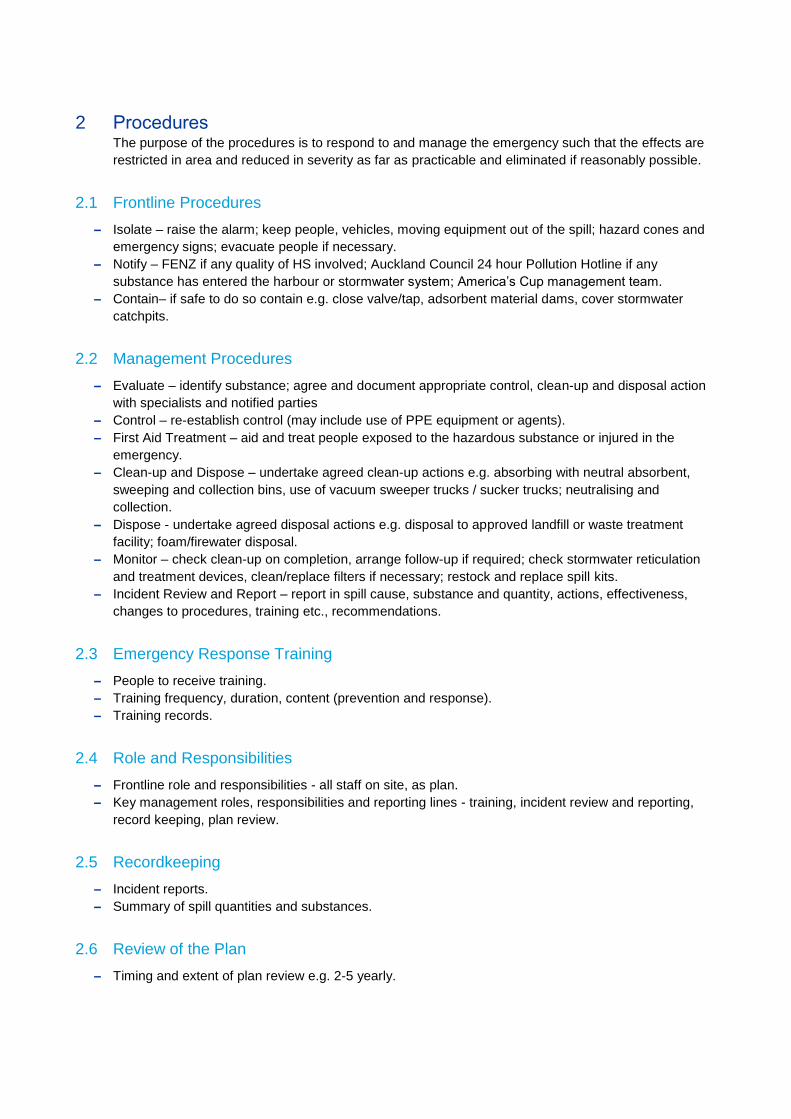
2 Procedures The purpose of the procedures is to respond to and manage the emergency such that the effects are
restricted in area and reduced in severity as far as practicable and eliminated if reasonably possible.
2.1 Frontline Procedures
– Isolate – raise the alarm; keep people, vehicles, moving equipment out of the spill; hazard cones and
emergency signs; evacuate people if necessary.
– Notify – FENZ if any quality of HS involved; Auckland Council 24 hour Pollution Hotline if any
substance has entered the harbour or stormwater system; America’s Cup management team.
– Contain– if safe to do so contain e.g. close valve/tap, adsorbent material dams, cover stormwater
catchpits.
2.2 Management Procedures
– Evaluate – identify substance; agree and document appropriate control, clean-up and disposal action
with specialists and notified parties
– Control – re-establish control (may include use of PPE equipment or agents).
– First Aid Treatment – aid and treat people exposed to the hazardous substance or injured in the
emergency.
– Clean-up and Dispose – undertake agreed clean-up actions e.g. absorbing with neutral absorbent,
sweeping and collection bins, use of vacuum sweeper trucks / sucker trucks; neutralising and
collection.
– Dispose - undertake agreed disposal actions e.g. disposal to approved landfill or waste treatment
facility; foam/firewater disposal.
– Monitor – check clean-up on completion, arrange follow-up if required; check stormwater reticulation
and treatment devices, clean/replace filters if necessary; restock and replace spill kits.
– Incident Review and Report – report in spill cause, substance and quantity, actions, effectiveness,
changes to procedures, training etc., recommendations.
2.3 Emergency Response Training
– People to receive training.
– Training frequency, duration, content (prevention and response).
– Training records.
2.4 Role and Responsibilities
– Frontline role and responsibilities - all staff on site, as plan.
– Key management roles, responsibilities and reporting lines - training, incident review and reporting,
record keeping, plan review.
2.5 Recordkeeping
– Incident reports.
– Summary of spill quantities and substances.
2.6 Review of the Plan
– Timing and extent of plan review e.g. 2-5 yearly.

Appendices
Appendix A: Site Drainage Plans
Appendix B: Spill Kit Contents List
Appendix C: Spill Kit Locations and Signage
ITA Spill Response Plan
Appendix B
ITA Environmental and Hazardous Substances Management Plan - Draft Table of Contents
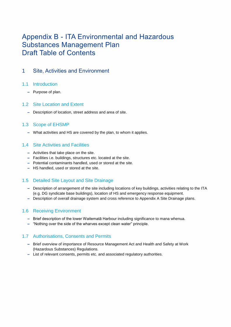
Appendix B - ITA Environmental and Hazardous Substances Management Plan Draft Table of Contents
1 Site, Activities and Environment
1.1 Introduction
– Purpose of plan.
1.2 Site Location and Extent
– Description of location, street address and area of site.
1.3 Scope of EHSMP
– What activities and HS are covered by the plan, to whom it applies.
1.4 Site Activities and Facilities
– Activities that take place on the site.
– Facilities i.e. buildings, structures etc. located at the site.
– Potential contaminants handled, used or stored at the site.
– HS handled, used or stored at the site.
1.5 Detailed Site Layout and Site Drainage
– Description of arrangement of the site including locations of key buildings, activities relating to the ITA
(e.g. DG syndicate base buildings), location of HS and emergency response equipment.
– Description of overall drainage system and cross reference to Appendix A Site Drainage plans.
1.6 Receiving Environment
– Brief description of the lower Waitematā Harbour including significance to mana whenua.
– “Nothing over the side of the wharves except clean water” principle.
1.7 Authorisations, Consents and Permits
– Brief overview of importance of Resource Management Act and Health and Safety at Work
(Hazardous Substances) Regulations.
– List of relevant consents, permits etc. and associated regulatory authorities.
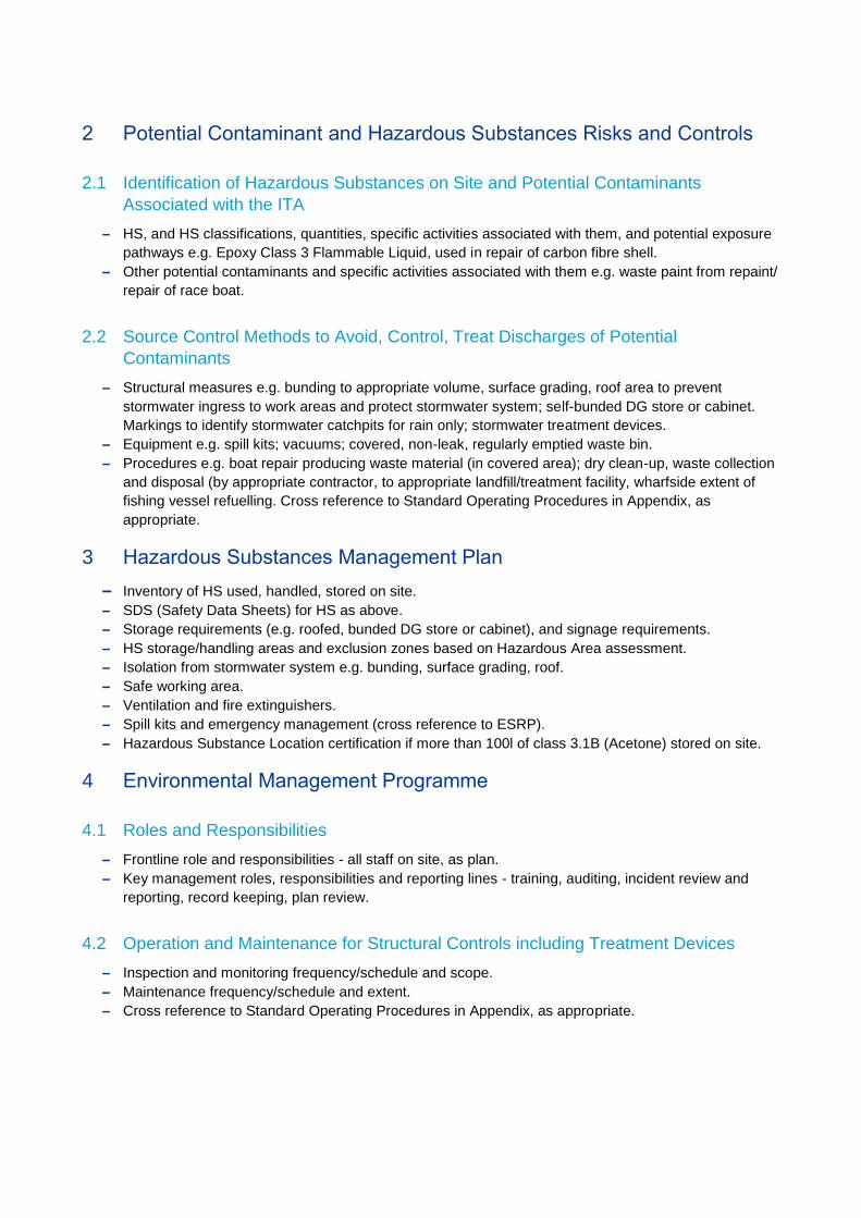
2 Potential Contaminant and Hazardous Substances Risks and Controls
2.1 Identification of Hazardous Substances on Site and Potential Contaminants
Associated with the ITA
– HS, and HS classifications, quantities, specific activities associated with them, and potential exposure
pathways e.g. Epoxy Class 3 Flammable Liquid, used in repair of carbon fibre shell.
– Other potential contaminants and specific activities associated with them e.g. waste paint from repaint/
repair of race boat.
2.2 Source Control Methods to Avoid, Control, Treat Discharges of Potential
Contaminants
– Structural measures e.g. bunding to appropriate volume, surface grading, roof area to prevent
stormwater ingress to work areas and protect stormwater system; self-bunded DG store or cabinet.
Markings to identify stormwater catchpits for rain only; stormwater treatment devices.
– Equipment e.g. spill kits; vacuums; covered, non-leak, regularly emptied waste bin.
– Procedures e.g. boat repair producing waste material (in covered area); dry clean-up, waste collection
and disposal (by appropriate contractor, to appropriate landfill/treatment facility, wharfside extent of
fishing vessel refuelling. Cross reference to Standard Operating Procedures in Appendix, as
appropriate.
3 Hazardous Substances Management Plan
– Inventory of HS used, handled, stored on site. – SDS (Safety Data Sheets) for HS as above.
– Storage requirements (e.g. roofed, bunded DG store or cabinet), and signage requirements.
– HS storage/handling areas and exclusion zones based on Hazardous Area assessment.
– Isolation from stormwater system e.g. bunding, surface grading, roof.
– Safe working area.
– Ventilation and fire extinguishers.
– Spill kits and emergency management (cross reference to ESRP).
– Hazardous Substance Location certification if more than 100l of class 3.1B (Acetone) stored on site.
4 Environmental Management Programme
4.1 Roles and Responsibilities
– Frontline role and responsibilities - all staff on site, as plan.
– Key management roles, responsibilities and reporting lines - training, auditing, incident review and
reporting, record keeping, plan review.
4.2 Operation and Maintenance for Structural Controls including Treatment Devices
– Inspection and monitoring frequency/schedule and scope.
– Maintenance frequency/schedule and extent.
– Cross reference to Standard Operating Procedures in Appendix, as appropriate.
4.3 Reporting and Review of EHSMP
– Incident reports and summary of spill quantities and substance (cross reference to Emergency Spill
Response Plan).
– Regular assessment of performance of EHSMP and report.
– Timing and extent of plan review e.g. 2-5 yearly.
Appendices
Appendix A: Site Drainage Plans
Appendix B: Resource Consents and Permits
Appendix C: Treatment Device Plans, Operation and Maintenance Manuals
Appendix D: Standard Operating Procedures
Appendix C
Stormwater Treatment Concept Design Calculation & Sketch
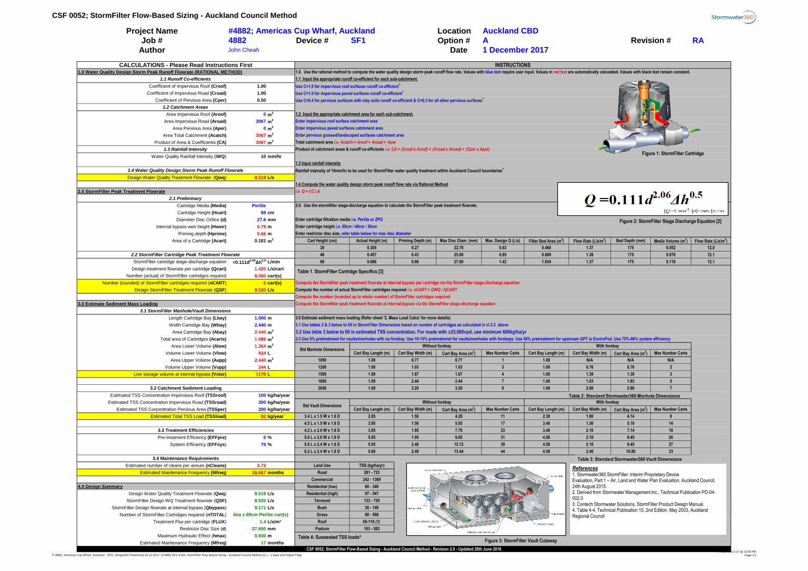
CSF 0052; StormFilter Flow-Based Sizing - Auckland Council Method
Project Name Location
Job # Device # Option # RA
Author Date
Coefficient of Impervious Roof (Croof) 1.00
Coefficient of Impervious Road (Croad) 1.00
Coefficient of Pervious Area (Cper) 0.50
Area Impervious Roof (Aroof) 0 m2
Area Impervious Road (Aroad) 3067 m2
Area Pervious Area (Aper) 0 m2
Area Total Catchment (Acatch) 3067 m2
Product of Area & Coefficients (CA) 3067 m2
Water Quality Rainfall Intensity (iWQ) 10 mm/hr
Design Water Quality Treatment Flowrate (Qwq) 8.519 L/s
Cartridge Media (Media) Perlite
Cartridge Height (Hcart) 69 cm
Diameter Disc Orifice (d) 27.6 mm
Internal bypass weir height (Hweir) 0.79 m
Priming depth (Hprime) 0.66 m
Area of a Cartridge (Acart) 0.181 m2 Cart Height (cm) Actual Height (m) Priming Depth (m) Max Disc Diam. (mm) Max. Design Q (L/s) Filter Bed Area (m
2) Flow Rate (L/s/m
2) Bed Depth (mm) Media Volume (m
3) Flow Rate (L/s/m
3)
30 0.305 0.27 22.70 0.63 0.460 1.37 175 0.052 12.0
46 0.457 0.43 25.00 0.95 0.689 1.38 175 0.078 12.1
StormFilter cartridge stage-discharge equation =0.111d2.06
Δh0.5 L/min 69 0.686 0.66 27.60 1.42 1.034 1.37 175 0.118 12.1
Design treatment flowrate per cartridge (Qcart) 1.420 L/s/cart
Number (actual) of StormFilter cartridges required 6.000 cart(s)
Number (rounded) of StormFilter cartridges required (nCART) 6 cart(s)
Design StormFilter Treatment Flowrate (QSF) 8.520 L/s
Length Cartridge Bay (Lbay) 1.000 m
Width Cartridge Bay (Wbay) 2.440 m
Area Cartridge Bay (Abay) 2.440 m2
Total area of Cartridges (Acarts) 1.086 m2
Area Lower Volume (Alow) 1.354 m2
Volume Lower Volume (Vlow) 934 L Cart Bay Length (m) Cart Bay Width (m) Cart Bay Area (m2) Max Number Carts Cart Bay Length (m) Cart Bay Width (m) Cart Bay Area (m
2) Max Number Carts
Area Upper Volume (Aupp) 2.440 m2 1050 1.00 0.77 0.77 1 1.00 N/A N/A N/A
Volume Upper Volume (Vupp) 244 L 1200 1.00 1.03 1.03 3 1.00 0.76 0.76 2
Live storage volume at internal bypass (Vstor) 1178 L 1500 1.00 1.67 1.67 4 1.00 1.39 1.39 3
1800 1.00 2.44 2.44 7 1.00 1.83 1.83 5
2050 1.00 3.20 3.20 9 1.00 2.80 2.80 7
Estimated TSS Concentration Impervious Roof (TSSroof) 100 kg/ha/year
Estimated TSS Concentration Impervious Road (TSSroad) 300 kg/ha/year
Estimated TSS Concentration Pervious Area (TSSper) 200 kg/ha/year Cart Bay Length (m) Cart Bay Width (m) Cart Bay Area (m2) Max Number Carts Cart Bay Length (m) Cart Bay Width (m) Cart Bay Area (m
2) Max Number Carts
Estimated Total TSS Load (TSSload) 92 kg/year 3.4 L x 1.5 W x 1.8 D 2.85 1.50 4.28 11 2.30 1.80 4.14 8
4.5 L x 1.5 W x 1.8 D 3.95 1.50 5.93 17 3.40 1.50 5.10 14
4.2 L x 2.0 W x 1.8 D 3.95 1.95 7.70 23 3.40 2.10 7.14 18
Pre-treatment Efficiency (EFFpre) 0 % 5.6 L x 2.0 W x 1.8 D 5.05 1.95 9.85 31 4.50 2.10 9.45 26
System Efficiency (EFFsys) 75 % 5.6 L x 2.4 W x 1.8 D 5.05 2.40 12.12 39 4.50 2.10 9.45 27
6.2 L x 2.4 W x 1.8 D 5.60 2.40 13.44 44 4.50 2.40 10.80 33
Estimated number of cleans per annum (nCleans) 0.72 Land Use TSS (kg/ha/yr)
Estimated Maintenance Frequency (Mfreq) 16.667 months Road 281 - 723
Commercial 242 - 1369
Residential (low) 60 - 340
Design Water Quality Treatment Flowrate (Qwq) 8.519 L/s Residential (high) 97 - 547
StormFilter Design WQ Treatment flowrate (QSF) 8.520 L/s Terraced 133 - 755
StormFilter Design flowrate at internal bypass (Qbypass) 9.171 L/s Bush 26 - 146
Number of StormFilter Cartridges required (nTOTAL) Grass 80 - 588
Treatment Flux per cartridge (FLUX) 1.4 L/s/m² Roof 50-110 (1)
Restrictor Disc Size (d) 27.600 mm Pasture 103 - 583
Maximum Hydraulic Effect (hmax) 0.930 m
Estimated Maintenance Frequency (Mfreq) 17 months
#4882; Americas Cup Wharf, Auckland Auckland CBD
Revision #A
CALCULATIONS - Please Read Instructions First
4882 SF1
INSTRUCTIONS
1 December 2017John Cheah
1.3 Input rainfall intensity
Std Vault Dimensions
Std Manhole Dimensions
Without forebay
Compute the Stormfilter peak treatment flowrate at internal bypass via the StormFilter stage-discharge equation
3.0 Estimate sediment mass loading (Refer sheet '2. Mass Load Calcs' for more details)
3.3 Use 0% pretreatment for vaults/manholes with no forebay. Use 10-15% pretreatmnet for vaults/manholes with forebays. Use 50% pretreatment for upstream GPT ie EnviroPod. Use 75%-90% system efficiency
3.1 Use tables 2 & 3 below to fill in StormFilter Dimensions based on number of cartridges as calculated in cl 2.2 above
CSF 0052; StormFilter Flow-Based Sizing - Auckland Council Method - Revision 2.0 - Updated 28th June 2016
1.2 Catchment Areas
With forebay
Rainfall intensity of 10mm/hr to be used for StormFilter water quality treatment within Auckland Council boundaries1
1.4 Compute the water quality design storm peak runoff flow rate via Rational Method
i.e. Q = f.C.i.A
2.0. Use the stormfilter stage-discharge equation to calculate the StormFilter peak treatment flowrate.
Enter cartridge filtration media i.e. Perlite or ZPG
6ea x 69cm Perlite cart(s)
1.2 Input the appropriate catchment area for each sub-catchment.
Enter impervious roof surface catchment area
Enter impervious paved surfaces catchment area
Enter pervious grassed/landscaped surfaces catchment area
1.1 Runoff Co-efficients
1.3 Rainfall Intensity
3.2 Catchment Sediment Loading
1.0 Water Quality Design Storm Peak Runoff Flowrate (RATIONAL METHOD)
1.4 Water Quality Design Storm Peak Runoff Flowrate
2.0 StormFilter Peak Treatment Flowrate
2.1 Preliminary
2.2 StormFilter Cartridge Peak Treatment Flowrate
3.0 Estimate Sediment Mass Loading
3.1 StormFilter Manhole/Vault Dimensions
1.0. Use the rational method to compute the water quality design storm peak runoff flow rate. Values with blue text require user input. Values in red text are automatically calculated. Values with black text remain constant.
1.1 Input the appropriate runoff co-efficient for each sub-catchment.
Use C=1.0 for impervious roof surfaces runoff co-efficient1
Use C=1.0 for impervious paved surfaces runoff co-efficient1
Use C=0.4 for pervious surfaces with clay soils runoff co-efficient & C=0.3 for all other pervious surfaces1
Total catchment area i.e. Acatch = Aroof + Aroad + Aper
Product of catchment areas & runoff co-efficients i.e. CA = (Croof x Aroof) + (Croad x Aroad) + (Cper x Aper)
3.3 Treatment Efficiencies
4.0 Design Summary
3.4 Maintenance Requirements
Compute the Stormfilter peak treatment flowrate at internal bypass per cartridge via the StormFilter stage-discharge equation
Compute the number of actual StormFilter cartridges required i.e. nCART = QWQ / QCART
Enter cartridge height i.e. 69cm / 46cm / 30cm
Enter restrictor disc size, refer table below for max disc diameter
Without forebay With forebay
3.2 Use table 3 below to fill in estimated TSS concentration. For roads with ≥25,000vpd, use minimum 600kg/ha/yr
Compute the number (rounded up to whole number) of StormFilter cartridges required
Figure 2: StormFilter Stage Discharge Equation [2]
Table 1. StormFilter Cartridge Specifics [3]
Figure 1: StormFilter Cartridge
Figure 3: StormFilter Vault Cutaway
Table 2: Standard Stormwater360 Manhole Dimensions
Table 3: Standard Stormwater360 Vault Dimensions
Table 4: Suggested TSS loads4
References1. Stormwater360 StormFilter: Interim Proprietary DeviceEvaluation, Part 1 – Air, Land and Water Plan Evaluation, Auckland Council, 24th August 2015.2. Derived from Stormwater Management Inc., Technical Publication PD-04-002.03. Contech Stormwater Solutions, StormFilter Product Design Manual.4. Table 4-4, Technical Publication 10, 2nd Edition, May 2003, Auckland Regional Council
P:\4882; Americas Cup Wharf, Auckland - SF\5. Design\RA Preliminary 01-12-2017 JC\4882-SF1-A-RA; StormFilter Flow-Based Sizing - Auckland Council Method v2.1 - 1.Input and Output PagePrinted 01-12-17 @ 12:55 PM
Page 1/1
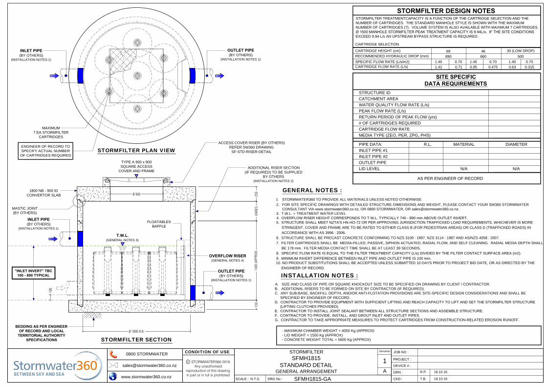
TYPE A 900 x 900
SQUARE ACCESS
COVER AND FRAME
ACCESS COVER RISER (BY OTHERS)
REFER SW360 DRAWING
SF-STD-RISER-DETAIL
150
250
1400
(APP
ROX)
VARI
ESOVERFLOW RISER
(GENERAL NOTES 4)
OUTLET PIPE
(BY OTHERS)
(INSTALLATION NOTES 1)
T.W.L.
(GENERAL NOTES 3)
FLOATABLES
BAFFLE
BEDDING AS PER ENGINEER
OF RECORD AND LOCAL
TERRITORIAL AUTHORITY
SPECIFICATIONS
Ø 1800 N.B.
STORMFILTER SECTION
"INLET INVERT" TBC
100 - 890 TYPICAL
100
INLET PIPE
(BY OTHERS)
(INSTALLATION NOTES 1)
MASTIC JOINT
(BY OTHERS)
1800 NB - 900 ID
CONVERTOR SLAB
ADDITIONAL RISER SECTION
(IF REQUIRED) TO BE SUPPLIED
BY OTHERS
(INSTALLATION NOTES 2)
INLET PIPE
(BY OTHERS)
(INSTALLATION NOTES 1)
OUTLET PIPE
(BY OTHERS)
(INSTALLATION NOTES 1)
MAXIMUM
7 EA STORMFILTER
CARTRIDGES
STORMFILTER PLAN VIEW
Ø 900
STORMFILTER TREATMENTCAPACITY IS A FUNCTION OF THE CARTRIDGE SELECTION AND THE
NUMBER OF CARTRIDGES. THE STANDARD MANHOLE STYLE IS SHOWN WITH THE MAXIMUM
NUMBER OF CARTRIDGES (7). VOLUME SYSTEM IS ALSO AVAILABLE WITH MAXIMUM 7 CARTRIDGES.
Ø 1500 MANHOLE STORMFILTER PEAK TREATMENT CAPACITY IS 9.94L/s. IF THE SITE CONDITIONS
EXCEED 9.94 L/s AN UPSTREAM BYPASS STRUCTURE IS REQUIRED.
STORMFILTER DESIGN NOTES
CARTRIDGE HEIGHT (cm)
SPECIFIC FLOW RATE (L/s/m2)
CARTRIDGE FLOW RATE (L/s)
RECOMMENDED HYDRAULIC DROP (mm)
69 46
30 (LOW DROP)
890 660 500
1.40
1.42
0.70 1.40 0.70 1.40 0.70
0.71 0.95 0.475 0.63 0.315
CARTRIDGE SELECTION
STRUCTURE ID
WATER QUALITY FLOW RATE (L/s)
PEAK FLOW RATE (L/s)
RETURN PERIOD OF PEAK FLOW (yrs)
# OF CARTRIDGES REQUIRED
MEDIA TYPE (ZEO, PER, ZPG, PHS)
PIPE DATA: R.L. MATERIAL
INLET PIPE #1
INLET PIPE #2
OUTLET PIPE
SITE SPECIFIC
DATA REQUIREMENTS
LID LEVEL
CARTRIDGE FLOW RATE
AS PER ENGINEER OF RECORD
DIAMETER
N/A N/A
CATCHMENT AREA
ENGINEER OF RECORD TO
SPECIFY ACTUAL NUMBER
OF CARTRIDGES REQUIRED
DRAWING
STORMFILTER
SFMH1815
STANDARD DETAIL
GENERAL ARRANGEMENT
1
A18.10.16
18.10.16T.B.
SFMH1815-GA
N.T.S.
DEVICE # :
JOB NO :
PROJECT :
STORMWATER360 2016Any unauthorised
reproduction of this drawingin part or in full is prohibited
C
CONDITION OF USE0800 STORMWATER
www.stormwater360.co.nz
DRN :
CKD :SCALE : DRG No :
R.P.
1 STORMWATER360 TO PROVIDE ALL MATERIALS UNLESS NOTED OTHERWISE.
2. FOR SITE SPECIFIC DRAWINGS WITH DETAILED STRUCTURE DIMENSIONS AND WEIGHT, PLEASE CONTACT YOUR SW360 STORMWATER
CONSULTANT VIA www.stormwater360.co.nz, OR 0800 STORMWATER, OR [email protected].
3. T.W.L. = TREATMENT WATER LEVEL
4. OVERFLOW RISER HEIGHT CORRESPONDS TO T.W.L. TYPICALLY 740 - 890 mm ABOVE OUTLET INVERT.
5. STRUCTURE SHALL MEET NZTA'S HN-HO-72 OR PER APPROVING JURISDICTION TRAFFICKED LOAD REQUIREMENTS, WHICHEVER IS MORE
STRINGENT. COVER AND FRAME ARE TO BE RATED TO EITHER CLASS B (FOR PEDESTRIAN AREAS) OR CLASS D (TRAFFICKED ROADS) IN
ACCORDANCE WITH AS 3996 : 2006.
6. STRUCTURE SHALL BE PRECAST CONCRETE CONFORMING TO NZS 3109 : 1997, NZS 3114 : 1987 AND AS/NZS 4058 : 2007.
7. FILTER CARTRIDGES SHALL BE MEDIA-FILLED, PASSIVE, SIPHON ACTUATED, RADIAL FLOW, AND SELF CLEANING. RADIAL MEDIA DEPTH SHALL
BE 178 mm. FILTER MEDIA CONTACT TIME SHALL BE AT LEAST 39 SECONDS.
8. SPECIFIC FLOW RATE IS EQUAL TO THE FILTER TREATMENT CAPACITY (L/s) DIVIDED BY THE FILTER CONTACT SURFACE AREA (m2).
9. MINIMUM INVERT DIFFERENCE BETWEEN INLET PIPE AND OUTLET PIPE IS 100 mm.
10. NO PRODUCT SUBSTITUTIONS SHALL BE ACCEPTED UNLESS SUBMITTED 10 DAYS PRIOR TO PROJECT BID DATE, OR AS DIRECTED BY THE
ENGINEER OF RECORD.
GENERAL NOTES :
INSTALLATION NOTES :A. SIZE AND CLASS OF PIPE OR SQUARE KNOCKOUT SIZE TO BE SPECIFIED ON DRAWING BY CLIENT / CONTRACTOR.
B. ADDITIONAL RISERS TO BE FORMED ON SITE BY CONTRACTOR (IF REQUIRED).
C. ANY SUB-BASE, BACKFILL DEPTH, AND/OR ANTI-FLOTATION PROVISIONS ARE SITE-SPECIFIC DESIGN CONSIDERATIONS AND SHALL BE
SPECIFIED BY ENGINEER OF RECORD.
D. CONTRACTOR TO PROVIDE EQUIPMENT WITH SUFFICIENT LIFTING AND REACH CAPACITY TO LIFT AND SET THE STORMFILTER STRUCTURE
(LIFTING CLUTCHES PROVIDED).
E. CONTRACTOR TO INSTALL JOINT SEALANT BETWEEN ALL STRUCTURE SECTIONS AND ASSEMBLE STRUCTURE.
F. CONTRACTOR TO PROVIDE, INSTALL, AND GROUT INLET AND OUTLET PIPES.
G. CONTRACTOR TO TAKE APPROPRIATE MEASURES TO PROTECT CARTRIDGES FROM CONSTRUCTION-RELATED EROSION RUNOFF.
- MAXIMUM CHAMBER WEIGHT = 4050 Kg (APPROX)
- LID WEIGHT = 1550 Kg (APPROX)
- CONCRETE WEIGHT TOTAL = 5600 Kg (APPROX)
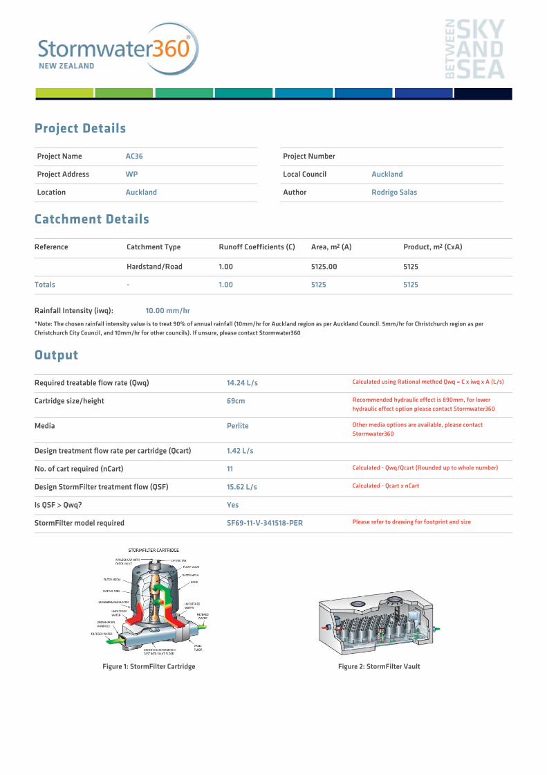
Project Details
Project Name AC36
Project Address WP
Location Auckland
Project Number
Local Council Auckland
Author Rodrigo Salas
Catchment Details
Reference Catchment Type Runoff Coefficients (C) Area, m2 (A) Product, m2 (CxA)
Hardstand/Road 1.00 5125.00 5125
Totals - 1.00 5125 5125
Rainfall Intensity (iwq): 10.00 mm/hr*Note: The chosen rainfall intensity value is to treat 90% of annual rainfall (10mm/hr for Auckland region as per Auckland Council. 5mm/hr for Christchurch region as perChristchurch City Council, and 10mm/hr for other councils). If unsure, please contact Stormwater360
Output
Required treatable flow rate (Qwq) 14.24 L/s Calculated using Rational method Qwq = C x iwq x A (L/s)
Cartridge size/height 69cm Recommended hydraulic effect is 890mm, for lowerhydraulic effect option please contact Stormwater360
Media Perlite Other media options are available, please contactStormwater360
Design treatment flow rate per cartridge (Qcart) 1.42 L/s
No. of cart required (nCart) 11 Calculated - Qwq/Qcart (Rounded up to whole number)
Design StormFilter treatment flow (QSF) 15.62 L/s Calculated - Qcart x nCart
Is QSF > Qwq? Yes
StormFilter model required SF69-11-V-341518-PER Please refer to drawing for footprint and size
Figure 1: StormFilter Cartridge Figure 2: StormFilter Vault
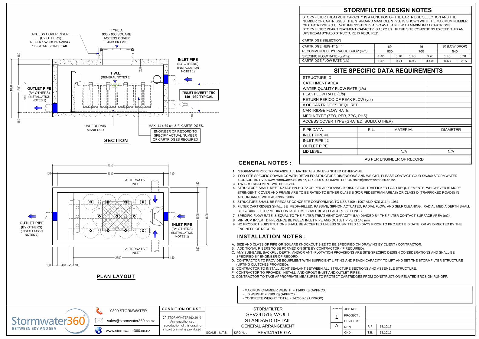
MAX. 11 x 69 cm S.F. CARTRIDGES.
930
150
150
1500
1800
150
PLAN LAYOUT
ALTERNATIVE
INLET
3650
3350150 150
100150 400
2850
ALTERNATIVE
INLET
UNDERDRAIN
MANIFOLD
"INLET INVERT" TBC
140 - 930 TYPICAL
1830
180
150
1500
140
TYPE A
900 x 900 SQUARE
ACCESS COVER
AND FRAME
200
ACCESS COVER RISER
(BY OTHERS)
REFER SW360 DRAWING
SF-STD-RISER-DETAIL
SECTION
OUTLET PIPE
(BY OTHERS)
(INSTALLATION
NOTES 1)
INLET PIPE
(BY OTHERS)
(INSTALLATION
NOTES 1)
OUTLET PIPE
(BY OTHERS)
(INSTALLATION
NOTES 1)
INLET PIPE
(BY OTHERS)
(INSTALLATION
NOTES 1)
T.W.L.
(GENERAL NOTES 3)
ENGINEER OF RECORD TO
SPECIFY ACTUAL NUMBER
OF CARTRIDGES REQUIRED
STRUCTURE ID
WATER QUALITY FLOW RATE (L/s)
PEAK FLOW RATE (L/s)
RETURN PERIOD OF PEAK FLOW (yrs)
# OF CARTRIDGES REQUIRED
MEDIA TYPE (ZEO, PER, ZPG, PHS)
PIPE DATA: R.L. MATERIAL
INLET PIPE #1
INLET PIPE #2
OUTLET PIPE
SITE SPECIFIC DATA REQUIREMENTS
LID LEVEL
CARTRIDGE FLOW RATE
AS PER ENGINEER OF RECORD
DIAMETER
N/A N/A
ACCESS COVER TYPE (GRATED, SOLID, OTHER)
- MAXIMUM CHAMBER WEIGHT = 11400 Kg (APPROX)
- LID WEIGHT = 3300 Kg (APPROX)
- CONCRETE WEIGHT TOTAL = 14700 Kg (APPROX)
DRAWING
STORMFILTER
SFV341515 VAULT
STANDARD DETAIL
GENERAL ARRANGEMENT
1
A18.10.16
18.10.16T.B.
SFV341515-GA
N.T.S.
DEVICE # :
JOB NO :
PROJECT :
STORMWATER360 2016Any unauthorised
reproduction of this drawingin part or in full is prohibited
C
CONDITION OF USE0800 STORMWATER
www.stormwater360.co.nz
DRN :
CKD :SCALE : DRG No :
R.P.
STORMFILTER DESIGN NOTES
CARTRIDGE HEIGHT (cm)
SPECIFIC FLOW RATE (L/s/m2)
CARTRIDGE FLOW RATE (L/s)
RECOMMENDED HYDRAULIC DROP (mm)
69 46
30 (LOW DROP)
930 700 540
1.40
1.42
0.70 1.40 0.70 1.40 0.70
0.71 0.95 0.475 0.63 0.315
CARTRIDGE SELECTION
STORMFILTER TREATMENTCAPACITY IS A FUNCTION OF THE CARTRIDGE SELECTION AND THE
NUMBER OF CARTRIDGES. THE STANDARD MANHOLE STYLE IS SHOWN WITH THE MAXIMUM NUMBER
OF CARTRIDGES (11). VOLUME SYSTEM IS ALSO AVAILABLE WITH MAXIMUM 11 CARTRIDGE.
STORMFILTER PEAK TREATMENT CAPACITY IS 15.62 L/s. IF THE SITE CONDITIONS EXCEED THIS AN
UPSTREAM BYPASS STRUCTURE IS REQUIRED.
CATCHMENT AREA
1 STORMWATER360 TO PROVIDE ALL MATERIALS UNLESS NOTED OTHERWISE.
2. FOR SITE SPECIFIC DRAWINGS WITH DETAILED STRUCTURE DIMENSIONS AND WEIGHT, PLEASE CONTACT YOUR SW360 STORMWATER
CONSULTANT VIA www.stormwater360.co.nz, OR 0800 STORMWATER, OR [email protected].
3. T.W.L. = TREATMENT WATER LEVEL
4. STRUCTURE SHALL MEET NZTA'S HN-HO-72 OR PER APPROVING JURISDICTION TRAFFICKED LOAD REQUIREMENTS, WHICHEVER IS MORE
STRINGENT. COVER AND FRAME ARE TO BE RATED TO EITHER CLASS B (FOR PEDESTRIAN AREAS) OR CLASS D (TRAFFICKED ROADS) IN
ACCORDANCE WITH AS 3996 : 2006.
5. STRUCTURE SHALL BE PRECAST CONCRETE CONFORMING TO NZS 3109 : 1997 AND NZS 3114 : 1987.
6. FILTER CARTRIDGES SHALL BE MEDIA-FILLED, PASSIVE, SIPHON ACTUATED, RADIAL FLOW, AND SELF CLEANING. RADIAL MEDIA DEPTH SHALL
BE 178 mm. FILTER MEDIA CONTACT TIME SHALL BE AT LEAST 39 SECONDS.
7. SPECIFIC FLOW RATE IS EQUAL TO THE FILTER TREATMENT CAPACITY (L/s) DIVIDED BY THE FILTER CONTACT SURFACE AREA (m2).
8. MINIMUM INVERT DIFFERENCE BETWEEN INLET PIPE AND OUTLET PIPE IS 140 mm.
9. NO PRODUCT SUBSTITUTIONS SHALL BE ACCEPTED UNLESS SUBMITTED 10 DAYS PRIOR TO PROJECT BID DATE, OR AS DIRECTED BY THE
ENGINEER OF RECORD.
GENERAL NOTES :
INSTALLATION NOTES :A. SIZE AND CLASS OF PIPE OR SQUARE KNOCKOUT SIZE TO BE SPECIFIED ON DRAWING BY CLIENT / CONTRACTOR.
B. ADDITIONAL RISERS TO BE FORMED ON SITE BY CONTRACTOR (IF REQUIRED).
C. ANY SUB-BASE, BACKFILL DEPTH, AND/OR ANTI-FLOTATION PROVISIONS ARE SITE-SPECIFIC DESIGN CONSIDERATIONS AND SHALL BE
SPECIFIED BY ENGINEER OF RECORD.
D. CONTRACTOR TO PROVIDE EQUIPMENT WITH SUFFICIENT LIFTING AND REACH CAPACITY TO LIFT AND SET THE STORMFILTER STRUCTURE
(LIFTING CLUTCHES PROVIDED).
E. CONTRACTOR TO INSTALL JOINT SEALANT BETWEEN ALL STRUCTURE SECTIONS AND ASSEMBLE STRUCTURE.
F. CONTRACTOR TO PROVIDE, INSTALL, AND GROUT INLET AND OUTLET PIPES.
G. CONTRACTOR TO TAKE APPROPRIATE MEASURES TO PROTECT CARTRIDGES FROM CONSTRUCTION-RELATED EROSION RUNOFF.

Project Details
Project Name AC36
Project Address WP
Location Auckland
Project Number
Local Council Auckland
Author Rodrigo Salas
Catchment Details
Reference Catchment Type Runoff Coefficients (C) Area, m2 (A) Product, m2 (CxA)
Hardstand/Road 1.00 4000.00 4000
Totals - 1.00 4000 4000
Rainfall Intensity (iwq): 10.00 mm/hr*Note: The chosen rainfall intensity value is to treat 90% of annual rainfall (10mm/hr for Auckland region as per Auckland Council. 5mm/hr for Christchurch region as perChristchurch City Council, and 10mm/hr for other councils). If unsure, please contact Stormwater360
Output
Required treatable flow rate (Qwq) 11.11 L/s Calculated using Rational method Qwq = C x iwq x A (L/s)
Cartridge size/height 69cm Recommended hydraulic effect is 890mm, for lowerhydraulic effect option please contact Stormwater360
Media Perlite Other media options are available, please contactStormwater360
Design treatment flow rate per cartridge (Qcart) 1.42 L/s
No. of cart required (nCart) 8 Calculated - Qwq/Qcart (Rounded up to whole number)
Design StormFilter treatment flow (QSF) 11.36 L/s Calculated - Qcart x nCart
Is QSF > Qwq? Yes
StormFilter model required SF69-08-MH-2015-PER Please refer to drawing for footprint and size
Figure 1: StormFilter Cartridge Figure 2: StormFilter Vault
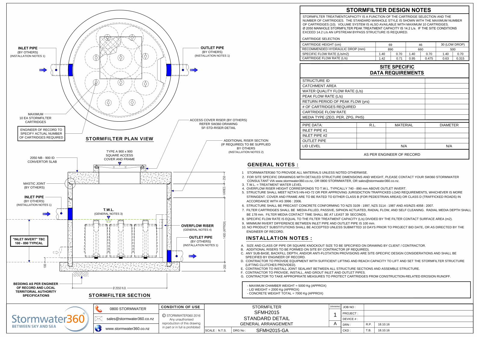
BEDDING AS PER ENGINEER
OF RECORD AND LOCAL
TERRITORIAL AUTHORITY
SPECIFICATIONS
TYPE A 900 x 900
SQUARE ACCESS
COVER AND FRAME
Ø 2050 N.B.
STORMFILTER SECTION
100
"INLET INVERT" TBC
100 - 890 TYPICAL
INLET PIPE
(BY OTHERS)
(INSTALLATION NOTES 1)
OUTLET PIPE
(BY OTHERS)
(INSTALLATION NOTES 1)
OVERFLOW RISER
(GENERAL NOTES 4)
200
1400
(APP
ROX)
250
VARI
ES
ADDITIONAL RISER SECTION
(IF REQUIRED) TO BE SUPPLIED
BY OTHERS
(INSTALLATION NOTES 2)
ACCESS COVER RISER (BY OTHERS)
REFER SW360 DRAWING
SF-STD-RISER-DETAIL
2050 NB - 900 ID
CONVERTOR SLAB
MASTIC JOINT
(BY OTHERS)
INLET PIPE
(BY OTHERS)
(INSTALLATION NOTES 1)
MAXIMUM
10 EA STORMFILTER
CARTRIDGES
OUTLET PIPE
(BY OTHERS)
(INSTALLATION NOTES 1)
STORMFILTER PLAN VIEW
STORMFILTER TREATMENTCAPACITY IS A FUNCTION OF THE CARTRIDGE SELECTION AND THE
NUMBER OF CARTRIDGES. THE STANDARD MANHOLE STYLE IS SHOWN WITH THE MAXIMUM NUMBER
OF CARTRIDGES (10). VOLUME SYSTEM IS ALSO AVAILABLE WITH MAXIMUM 10 CARTRIDGES.
Ø 2050 MANHOLE STORMFILTER PEAK TREATMENT CAPACITY IS 14.2 L/s. IF THE SITE CONDITIONS
EXCEED 14.2 L/s AN UPSTREAM BYPASS STRUCTURE IS REQUIRED.
T.W.L.
(GENERAL NOTES 3)
STORMFILTER DESIGN NOTES
CARTRIDGE HEIGHT (cm)
SPECIFIC FLOW RATE (L/s/m2)
CARTRIDGE FLOW RATE (L/s)
RECOMMENDED HYDRAULIC DROP (mm)
69 46
30 (LOW DROP)
890 660 500
1.40
1.42
0.70 1.40 0.70 1.40 0.70
0.71 0.95 0.475 0.63 0.315
CARTRIDGE SELECTION
STRUCTURE ID
WATER QUALITY FLOW RATE (L/s)
PEAK FLOW RATE (L/s)
RETURN PERIOD OF PEAK FLOW (yrs)
# OF CARTRIDGES REQUIRED
MEDIA TYPE (ZEO, PER, ZPG, PHS)
PIPE DATA: R.L. MATERIAL
INLET PIPE #1
INLET PIPE #2
OUTLET PIPE
SITE SPECIFIC
DATA REQUIREMENTS
LID LEVEL
CARTRIDGE FLOW RATE
AS PER ENGINEER OF RECORD
DIAMETER
N/A N/A
CATCHMENT AREA
ENGINEER OF RECORD TO
SPECIFY ACTUAL NUMBER
OF CARTRIDGES REQUIRED
1 STORMWATER360 TO PROVIDE ALL MATERIALS UNLESS NOTED OTHERWISE.
2. FOR SITE SPECIFIC DRAWINGS WITH DETAILED STRUCTURE DIMENSIONS AND WEIGHT, PLEASE CONTACT YOUR SW360 STORMWATER
CONSULTANT VIA www.stormwater360.co.nz, OR 0800 STORMWATER, OR [email protected].
3. T.W.L. = TREATMENT WATER LEVEL
4. OVERFLOW RISER HEIGHT CORRESPONDS TO T.W.L. TYPICALLY 740 - 890 mm ABOVE OUTLET INVERT.
5. STRUCTURE SHALL MEET NZTA'S HN-HO-72 OR PER APPROVING JURISDICTION TRAFFICKED LOAD REQUIREMENTS, WHICHEVER IS MORE
STRINGENT. COVER AND FRAME ARE TO BE RATED TO EITHER CLASS B (FOR PEDESTRIAN AREAS) OR CLASS D (TRAFFICKED ROADS) IN
ACCORDANCE WITH AS 3996 : 2006.
6. STRUCTURE SHALL BE PRECAST CONCRETE CONFORMING TO NZS 3109 : 1997, NZS 3114 : 1987 AND AS/NZS 4058 : 2007.
7. FILTER CARTRIDGES SHALL BE MEDIA-FILLED, PASSIVE, SIPHON ACTUATED, RADIAL FLOW, AND SELF CLEANING. RADIAL MEDIA DEPTH SHALL
BE 178 mm. FILTER MEDIA CONTACT TIME SHALL BE AT LEAST 39 SECONDS.
8. SPECIFIC FLOW RATE IS EQUAL TO THE FILTER TREATMENT CAPACITY (L/s) DIVIDED BY THE FILTER CONTACT SURFACE AREA (m2).
9. MINIMUM INVERT DIFFERENCE BETWEEN INLET PIPE AND OUTLET PIPE IS 100 mm.
10. NO PRODUCT SUBSTITUTIONS SHALL BE ACCEPTED UNLESS SUBMITTED 10 DAYS PRIOR TO PROJECT BID DATE, OR AS DIRECTED BY THE
ENGINEER OF RECORD.
GENERAL NOTES :
INSTALLATION NOTES :A. SIZE AND CLASS OF PIPE OR SQUARE KNOCKOUT SIZE TO BE SPECIFIED ON DRAWING BY CLIENT / CONTRACTOR.
B. ADDITIONAL RISERS TO BE FORMED ON SITE BY CONTRACTOR (IF REQUIRED).
C. ANY SUB-BASE, BACKFILL DEPTH, AND/OR ANTI-FLOTATION PROVISIONS ARE SITE-SPECIFIC DESIGN CONSIDERATIONS AND SHALL BE
SPECIFIED BY ENGINEER OF RECORD.
D. CONTRACTOR TO PROVIDE EQUIPMENT WITH SUFFICIENT LIFTING AND REACH CAPACITY TO LIFT AND SET THE STORMFILTER STRUCTURE
(LIFTING CLUTCHES PROVIDED).
E. CONTRACTOR TO INSTALL JOINT SEALANT BETWEEN ALL STRUCTURE SECTIONS AND ASSEMBLE STRUCTURE.
F. CONTRACTOR TO PROVIDE, INSTALL, AND GROUT INLET AND OUTLET PIPES.
G. CONTRACTOR TO TAKE APPROPRIATE MEASURES TO PROTECT CARTRIDGES FROM CONSTRUCTION-RELATED EROSION RUNOFF.
- MAXIMUM CHAMBER WEIGHT = 5000 Kg (APPROX)
- LID WEIGHT = 2000 Kg (APPROX)
- CONCRETE WEIGHT TOTAL = 7000 Kg (APPROX)
DRAWING
STORMFILTER
SFMH2015
STANDARD DETAIL
GENERAL ARRANGEMENT
1
A18.10.16
18.10.16T.B.
SFMH2015-GA
N.T.S.
DEVICE # :
JOB NO :
PROJECT :
STORMWATER360 2016Any unauthorised
reproduction of this drawingin part or in full is prohibited
C
CONDITION OF USE0800 STORMWATER
www.stormwater360.co.nz
DRN :
CKD :SCALE : DRG No :
R.P.
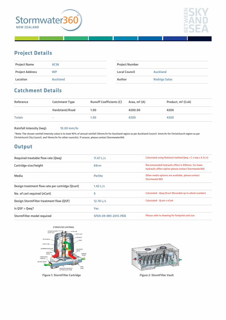
Project Details
Project Name AC36
Project Address WP
Location Auckland
Project Number
Local Council Auckland
Author Rodrigo Salas
Catchment Details
Reference Catchment Type Runoff Coefficients (C) Area, m2 (A) Product, m2 (CxA)
Hardstand/Road 1.00 4200.00 4200
Totals - 1.00 4200 4200
Rainfall Intensity (iwq): 10.00 mm/hr*Note: The chosen rainfall intensity value is to treat 90% of annual rainfall (10mm/hr for Auckland region as per Auckland Council. 5mm/hr for Christchurch region as perChristchurch City Council, and 10mm/hr for other councils). If unsure, please contact Stormwater360
Output
Required treatable flow rate (Qwq) 11.67 L/s Calculated using Rational method Qwq = C x iwq x A (L/s)
Cartridge size/height 69cm Recommended hydraulic effect is 890mm, for lowerhydraulic effect option please contact Stormwater360
Media Perlite Other media options are available, please contactStormwater360
Design treatment flow rate per cartridge (Qcart) 1.42 L/s
No. of cart required (nCart) 9 Calculated - Qwq/Qcart (Rounded up to whole number)
Design StormFilter treatment flow (QSF) 12.78 L/s Calculated - Qcart x nCart
Is QSF > Qwq? Yes
StormFilter model required SF69-09-MH-2015-PER Please refer to drawing for footprint and size
Figure 1: StormFilter Cartridge Figure 2: StormFilter Vault

BEDDING AS PER ENGINEER
OF RECORD AND LOCAL
TERRITORIAL AUTHORITY
SPECIFICATIONS
TYPE A 900 x 900
SQUARE ACCESS
COVER AND FRAME
Ø 2050 N.B.
STORMFILTER SECTION
100
"INLET INVERT" TBC
100 - 890 TYPICAL
INLET PIPE
(BY OTHERS)
(INSTALLATION NOTES 1)
OUTLET PIPE
(BY OTHERS)
(INSTALLATION NOTES 1)
OVERFLOW RISER
(GENERAL NOTES 4)
200
1400
(APP
ROX)
250
VARI
ES
ADDITIONAL RISER SECTION
(IF REQUIRED) TO BE SUPPLIED
BY OTHERS
(INSTALLATION NOTES 2)
ACCESS COVER RISER (BY OTHERS)
REFER SW360 DRAWING
SF-STD-RISER-DETAIL
2050 NB - 900 ID
CONVERTOR SLAB
MASTIC JOINT
(BY OTHERS)
INLET PIPE
(BY OTHERS)
(INSTALLATION NOTES 1)
MAXIMUM
10 EA STORMFILTER
CARTRIDGES
OUTLET PIPE
(BY OTHERS)
(INSTALLATION NOTES 1)
STORMFILTER PLAN VIEW
STORMFILTER TREATMENTCAPACITY IS A FUNCTION OF THE CARTRIDGE SELECTION AND THE
NUMBER OF CARTRIDGES. THE STANDARD MANHOLE STYLE IS SHOWN WITH THE MAXIMUM NUMBER
OF CARTRIDGES (10). VOLUME SYSTEM IS ALSO AVAILABLE WITH MAXIMUM 10 CARTRIDGES.
Ø 2050 MANHOLE STORMFILTER PEAK TREATMENT CAPACITY IS 14.2 L/s. IF THE SITE CONDITIONS
EXCEED 14.2 L/s AN UPSTREAM BYPASS STRUCTURE IS REQUIRED.
T.W.L.
(GENERAL NOTES 3)
STORMFILTER DESIGN NOTES
CARTRIDGE HEIGHT (cm)
SPECIFIC FLOW RATE (L/s/m2)
CARTRIDGE FLOW RATE (L/s)
RECOMMENDED HYDRAULIC DROP (mm)
69 46
30 (LOW DROP)
890 660 500
1.40
1.42
0.70 1.40 0.70 1.40 0.70
0.71 0.95 0.475 0.63 0.315
CARTRIDGE SELECTION
STRUCTURE ID
WATER QUALITY FLOW RATE (L/s)
PEAK FLOW RATE (L/s)
RETURN PERIOD OF PEAK FLOW (yrs)
# OF CARTRIDGES REQUIRED
MEDIA TYPE (ZEO, PER, ZPG, PHS)
PIPE DATA: R.L. MATERIAL
INLET PIPE #1
INLET PIPE #2
OUTLET PIPE
SITE SPECIFIC
DATA REQUIREMENTS
LID LEVEL
CARTRIDGE FLOW RATE
AS PER ENGINEER OF RECORD
DIAMETER
N/A N/A
CATCHMENT AREA
ENGINEER OF RECORD TO
SPECIFY ACTUAL NUMBER
OF CARTRIDGES REQUIRED
1 STORMWATER360 TO PROVIDE ALL MATERIALS UNLESS NOTED OTHERWISE.
2. FOR SITE SPECIFIC DRAWINGS WITH DETAILED STRUCTURE DIMENSIONS AND WEIGHT, PLEASE CONTACT YOUR SW360 STORMWATER
CONSULTANT VIA www.stormwater360.co.nz, OR 0800 STORMWATER, OR [email protected].
3. T.W.L. = TREATMENT WATER LEVEL
4. OVERFLOW RISER HEIGHT CORRESPONDS TO T.W.L. TYPICALLY 740 - 890 mm ABOVE OUTLET INVERT.
5. STRUCTURE SHALL MEET NZTA'S HN-HO-72 OR PER APPROVING JURISDICTION TRAFFICKED LOAD REQUIREMENTS, WHICHEVER IS MORE
STRINGENT. COVER AND FRAME ARE TO BE RATED TO EITHER CLASS B (FOR PEDESTRIAN AREAS) OR CLASS D (TRAFFICKED ROADS) IN
ACCORDANCE WITH AS 3996 : 2006.
6. STRUCTURE SHALL BE PRECAST CONCRETE CONFORMING TO NZS 3109 : 1997, NZS 3114 : 1987 AND AS/NZS 4058 : 2007.
7. FILTER CARTRIDGES SHALL BE MEDIA-FILLED, PASSIVE, SIPHON ACTUATED, RADIAL FLOW, AND SELF CLEANING. RADIAL MEDIA DEPTH SHALL
BE 178 mm. FILTER MEDIA CONTACT TIME SHALL BE AT LEAST 39 SECONDS.
8. SPECIFIC FLOW RATE IS EQUAL TO THE FILTER TREATMENT CAPACITY (L/s) DIVIDED BY THE FILTER CONTACT SURFACE AREA (m2).
9. MINIMUM INVERT DIFFERENCE BETWEEN INLET PIPE AND OUTLET PIPE IS 100 mm.
10. NO PRODUCT SUBSTITUTIONS SHALL BE ACCEPTED UNLESS SUBMITTED 10 DAYS PRIOR TO PROJECT BID DATE, OR AS DIRECTED BY THE
ENGINEER OF RECORD.
GENERAL NOTES :
INSTALLATION NOTES :A. SIZE AND CLASS OF PIPE OR SQUARE KNOCKOUT SIZE TO BE SPECIFIED ON DRAWING BY CLIENT / CONTRACTOR.
B. ADDITIONAL RISERS TO BE FORMED ON SITE BY CONTRACTOR (IF REQUIRED).
C. ANY SUB-BASE, BACKFILL DEPTH, AND/OR ANTI-FLOTATION PROVISIONS ARE SITE-SPECIFIC DESIGN CONSIDERATIONS AND SHALL BE
SPECIFIED BY ENGINEER OF RECORD.
D. CONTRACTOR TO PROVIDE EQUIPMENT WITH SUFFICIENT LIFTING AND REACH CAPACITY TO LIFT AND SET THE STORMFILTER STRUCTURE
(LIFTING CLUTCHES PROVIDED).
E. CONTRACTOR TO INSTALL JOINT SEALANT BETWEEN ALL STRUCTURE SECTIONS AND ASSEMBLE STRUCTURE.
F. CONTRACTOR TO PROVIDE, INSTALL, AND GROUT INLET AND OUTLET PIPES.
G. CONTRACTOR TO TAKE APPROPRIATE MEASURES TO PROTECT CARTRIDGES FROM CONSTRUCTION-RELATED EROSION RUNOFF.
- MAXIMUM CHAMBER WEIGHT = 5000 Kg (APPROX)
- LID WEIGHT = 2000 Kg (APPROX)
- CONCRETE WEIGHT TOTAL = 7000 Kg (APPROX)
DRAWING
STORMFILTER
SFMH2015
STANDARD DETAIL
GENERAL ARRANGEMENT
1
A18.10.16
18.10.16T.B.
SFMH2015-GA
N.T.S.
DEVICE # :
JOB NO :
PROJECT :
STORMWATER360 2016Any unauthorised
reproduction of this drawingin part or in full is prohibited
C
CONDITION OF USE0800 STORMWATER
www.stormwater360.co.nz
DRN :
CKD :SCALE : DRG No :
R.P.
Appendix D
Correspondence from Services Organisations & FENZ
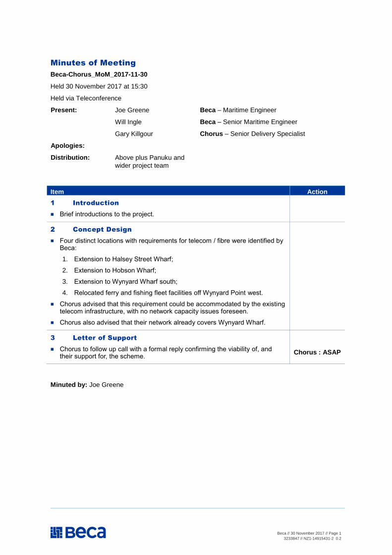
Beca // 30 November 2017 // Page 1
3233847 // NZ1-14915431-2 0.2
Minutes of Meeting
Beca-Chorus_MoM_2017-11-30
Held 30 November 2017 at 15:30
Held via Teleconference
Present: Joe Greene
Will Ingle
Gary Killgour
Beca – Maritime Engineer
Beca – Senior Maritime Engineer
Chorus – Senior Delivery Specialist
Apologies:
Distribution: Above plus Panuku and
wider project team
Item Action
1 Introduction
Brief introductions to the project.
2 Concept Design
Four distinct locations with requirements for telecom / fibre were identified by Beca:
1. Extension to Halsey Street Wharf;
2. Extension to Hobson Wharf;
3. Extension to Wynyard Wharf south;
4. Relocated ferry and fishing fleet facilities off Wynyard Point west.
Chorus advised that this requirement could be accommodated by the existing telecom infrastructure, with no network capacity issues foreseen.
Chorus also advised that their network already covers Wynyard Wharf.
3 Letter of Support
Chorus to follow up call with a formal reply confirming the viability of, and their support for, the scheme.
Chorus : ASAP
Minuted by: Joe Greene
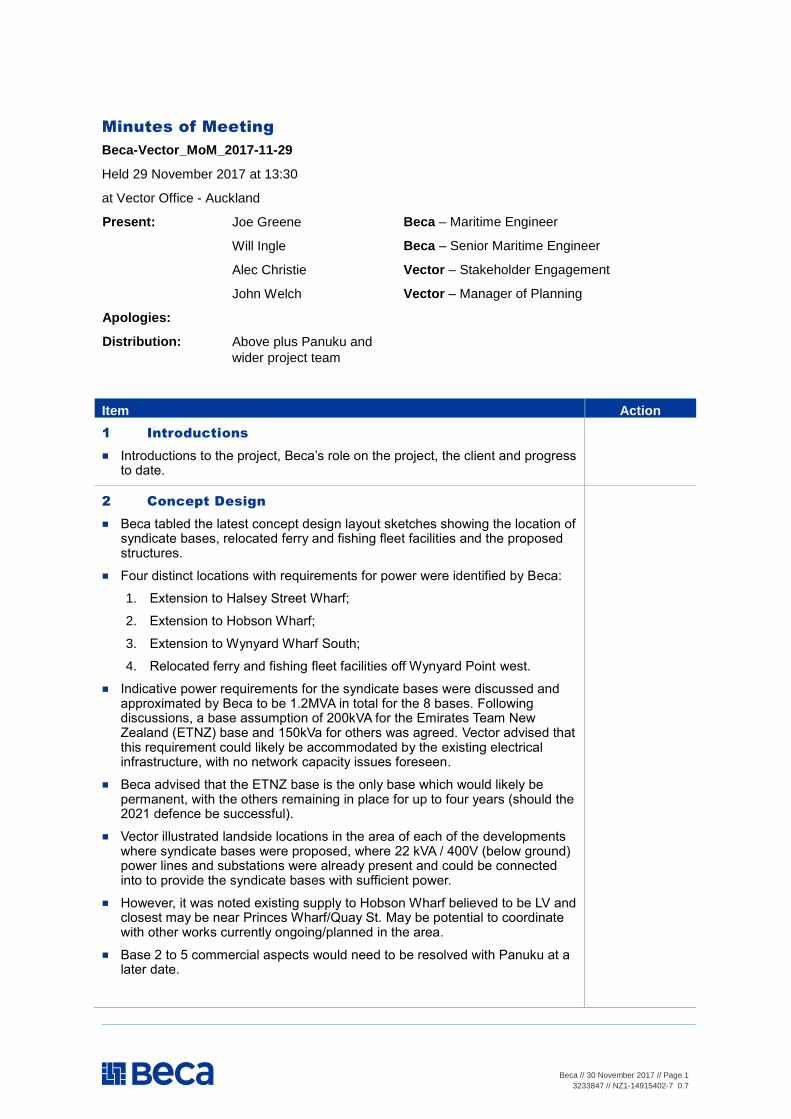
Beca // 30 November 2017 // Page 1
3233847 // NZ1-14915402-7 0.7
Minutes of Meeting
Beca-Vector_MoM_2017-11-29
Held 29 November 2017 at 13:30
at Vector Office - Auckland
Present: Joe Greene
Will Ingle
Alec Christie
John Welch
Beca – Maritime Engineer
Beca – Senior Maritime Engineer
Vector – Stakeholder Engagement
Vector – Manager of Planning
Apologies:
Distribution: Above plus Panuku and
wider project team
Item Action
1 Introductions
Introductions to the project, Beca’s role on the project, the client and progress to date.
2 Concept Design
Beca tabled the latest concept design layout sketches showing the location of syndicate bases, relocated ferry and fishing fleet facilities and the proposed structures.
Four distinct locations with requirements for power were identified by Beca:
1. Extension to Halsey Street Wharf;
2. Extension to Hobson Wharf;
3. Extension to Wynyard Wharf South;
4. Relocated ferry and fishing fleet facilities off Wynyard Point west.
Indicative power requirements for the syndicate bases were discussed and approximated by Beca to be 1.2MVA in total for the 8 bases. Following discussions, a base assumption of 200kVA for the Emirates Team New Zealand (ETNZ) base and 150kVa for others was agreed. Vector advised that this requirement could likely be accommodated by the existing electrical infrastructure, with no network capacity issues foreseen.
Beca advised that the ETNZ base is the only base which would likely be permanent, with the others remaining in place for up to four years (should the 2021 defence be successful).
Vector illustrated landside locations in the area of each of the developments where syndicate bases were proposed, where 22 kVA / 400V (below ground) power lines and substations were already present and could be connected into to provide the syndicate bases with sufficient power.
However, it was noted existing supply to Hobson Wharf believed to be LV and closest may be near Princes Wharf/Quay St. May be potential to coordinate with other works currently ongoing/planned in the area.
Base 2 to 5 commercial aspects would need to be resolved with Panuku at a later date.

Beca // 30 November 2017 // Page 2
3233847 // NZ1-14915402-7 0.7
Vector advised on minimising the length of cable required to supply the syndicate bases on Wynyard Wharf.
Vector noted that the ferry facilities currently do not have a significant demand for power and as such, provision of power to the relocated facilities should not pose a challenge.
3 Superyacht Berths
Beca highlighted the areas proposed for superyacht berthing and tabled the PIANC guidance on electrical supply to superyacht berths. Approximate power demand magnitudes were discussed, along with two options for supply (due to the demand being very significant):
1. Development of the existing power network infrastructure;
2. Provision of generators to power the superyachts.
Vector noted that if network upgrades were to be considered, there are a number of developments in the wider area which would benefit from co-ordination.
Vector requested time to consider the residual capacity in the existing power network infrastructure and determine the magnitude of upgrades or adaptations required to be able to accommodate a number of superyachts. Vector to advise on this residual network capacity as soon as possible.
Vector advised that Panuku might wish to consider upgrades to the power network in the areas being considered to better accommodate larger vessels such as superyachts etc.
Vector: ASAP
4 Letter of Support
Beca to send an email to Vector containing the tabled sketches and additional details on power demand, superyacht vessel requirements, sizes and locations.
Vector to then follow up with a formal letter of support for the project and outlining Vectors ability to accommodate the project power requirements.
Beca : 30/11/17
Vector : ASAP
Minuted by: Joe Greene
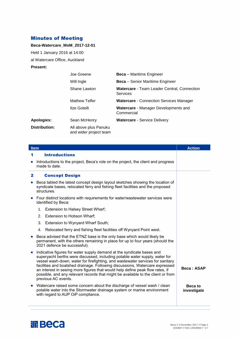
Beca // 4 December 2017 // Page 1
3233847 // NZ1-14919060-7 0.7
Minutes of Meeting
Beca-Watercare_MoM_2017-12-01
Held 1 January 2016 at 14:00
at Watercare Office, Auckland
Present:
Joe Greene Beca – Maritime Engineer
Will Ingle Beca – Senior Maritime Engineer
Shane Lawton Watercare - Team Leader Central, Connection
Services
Mathew Telfer Watercare - Connection Services Manager
Ilze Gotelli Watercare - Manager Developments and
Commercial
Apologies: Sean McHenry Watercare - Service Delivery
Distribution: All above plus Panuku
and wider project team
Item Action
1 Introductions
Introductions to the project, Beca’s role on the project, the client and progress made to date.
2 Concept Design
Beca tabled the latest concept design layout sketches showing the location of syndicate bases, relocated ferry and fishing fleet facilities and the proposed structures.
Four distinct locations with requirements for water/wastewater services were identified by Beca:
1. Extension to Halsey Street Wharf;
2. Extension to Hobson Wharf;
3. Extension to Wynyard Wharf South;
4. Relocated ferry and fishing fleet facilities off Wynyard Point west.
Beca advised that the ETNZ base is the only base which would likely be permanent, with the others remaining in place for up to four years (should the 2021 defence be successful).
Indicative figures for water supply demand at the syndicate bases and superyacht berths were discussed, including potable water supply, water for vessel wash-down, water for firefighting, and wastewater services for sanitary facilities and boatshed drainage. Following discussions, Watercare expressed an interest in seeing more figures that would help define peak flow rates, if possible, and any relevant records that might be available to the client or from previous AC events.
Watercare raised some concern about the discharge of vessel wash / clean potable water into the Stormwater drainage system or marine environment with regard to AUP OiP compliance.
Beca : ASAP
Beca to investigate
Beca // 4 December 2017 // Page 2
3233847 // NZ1-14919060-7 0.7
The concept design approach to water supply for firefighting at the syndicate bases was outlined by Beca and discussed, with the approach predominantly utilising water from the ocean via permanent dropper pipes. It was noted a supply of water sufficient for initial firefighting was likely to be required from the Watercare network.
Watercare illustrated landside locations in relatively close proximity to each of the developments where syndicate bases were proposed, where existing belowground infrastructure is present and with potential connection points.
It was noted that the existing water services infrastructure on Halsey Street Extension Wharf and Hobson Wharf are private and presumably owned and operated by Panuku. These wharf-based networks connect into the Watercare assets at locations on Jellicoe St and Hobson St.Watercare will review their belowground assets at the corner where Hobson St meets Quay St as it is unclear from the GIS plans where the public assets start and where the most appropriate point of connection would be.
Watercare noted that construction of the new pump station is currently underway near the corner of Daldy St and Pakenham St which will serve the vast majority of Wynyard Quarter. Completion of construction of this pumping station is likely to be in 2018.
Watercare also noted that the condition of the existing belowground infrastructure on Wynyard Point would benefit from a review prior to connection works being carried out. A CCTV condition survey assessment of the network on Wynyard Point would be of benefit due to the age of infrastructure.
Watercare requested Panuku contact details and expressed an interest in developing a Watercare/Panuku relationship and being involved and present at the consent stage to aid progress.
Watercare to review and feedback
Watercare to review and feedback
3 Letter of Support
Beca to send an email to Watercare containing a draft letter of support for the scheme.
Watercare to review and amend the wording, and respond.
Beca : 06.12.17
Watercare : 11.12.17
Minuted by: Joe Greene
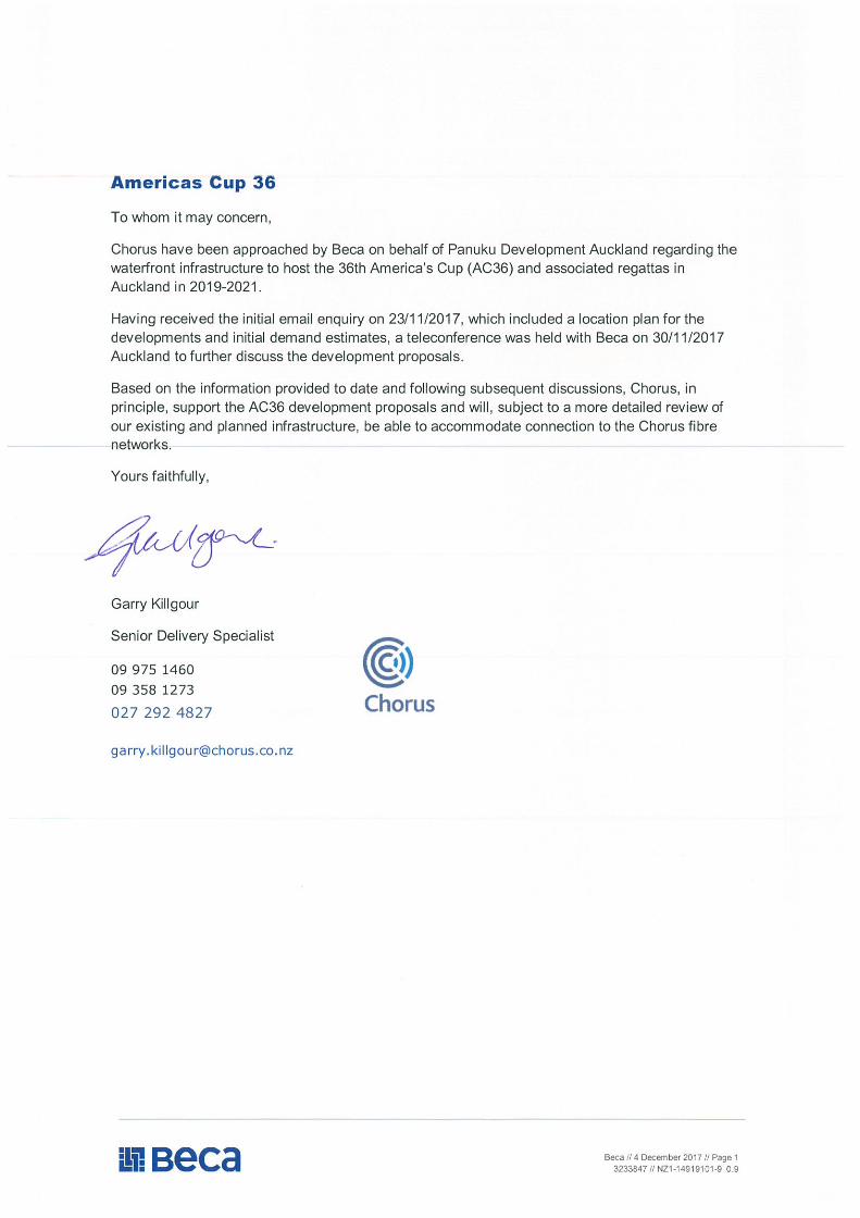
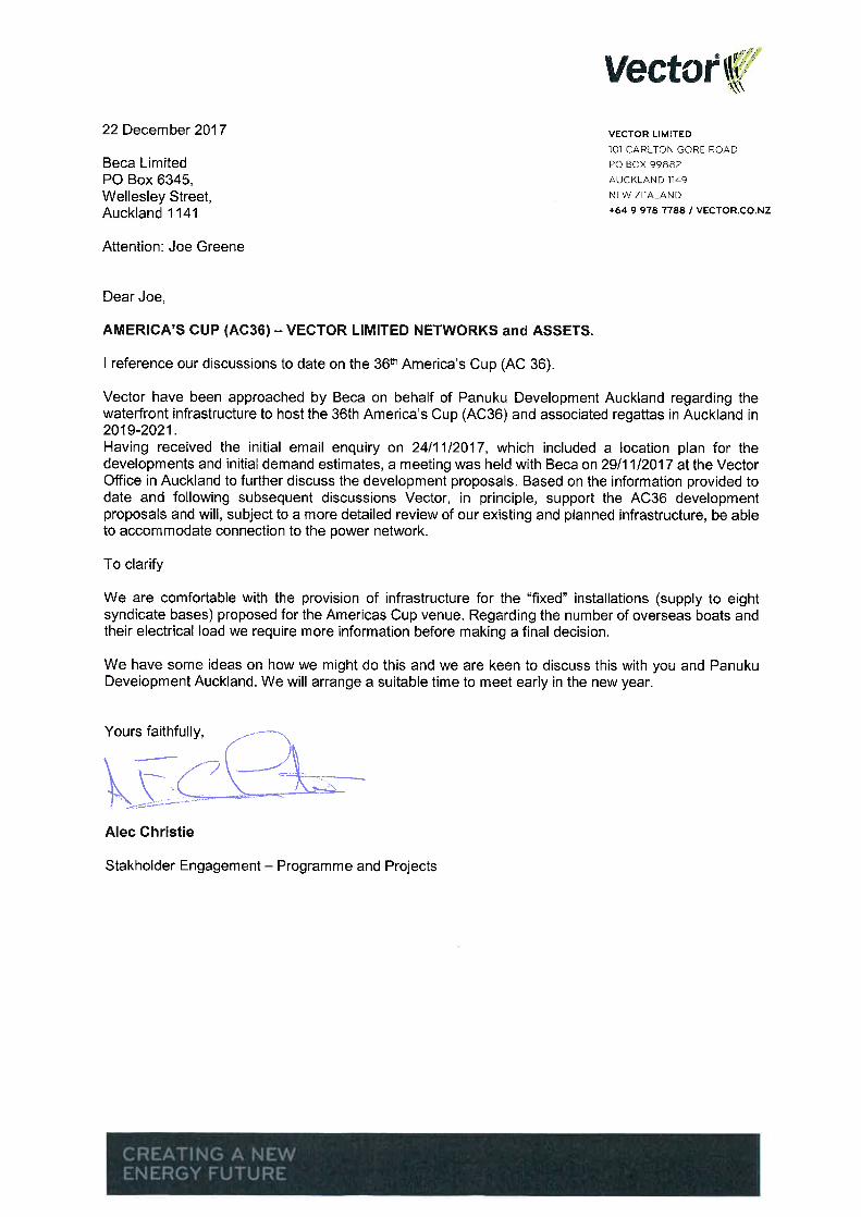
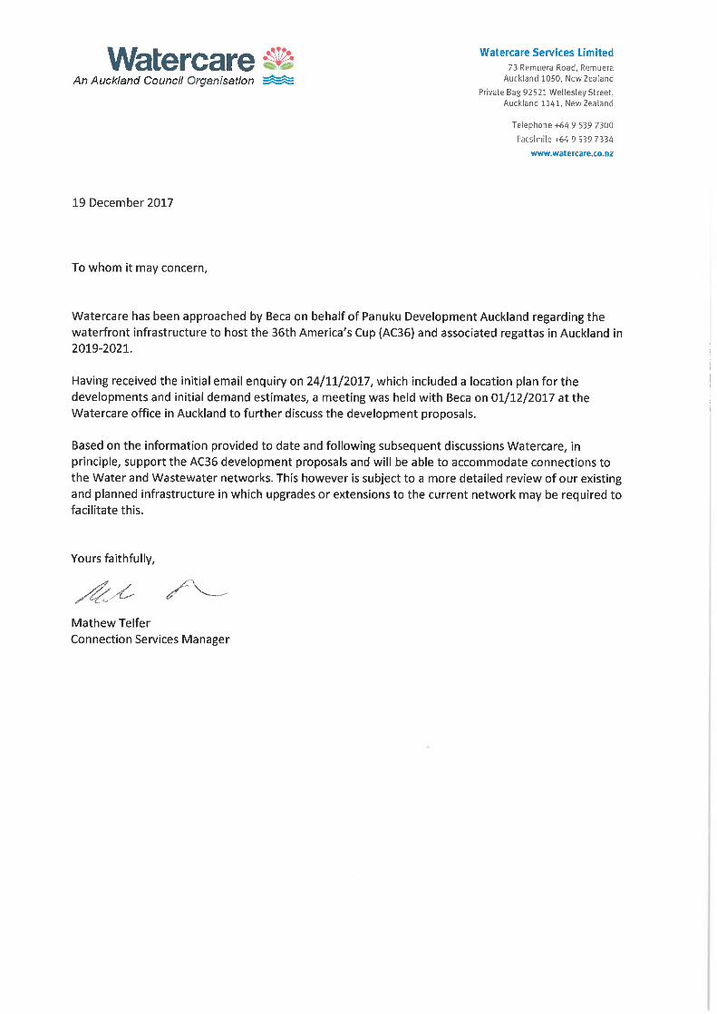
1
Paul Musson
From: Fox, Barry <[email protected]>
Sent: Wednesday, 4 April 2018 8:37 a.m.
To: Paul Musson
Subject: RE: AC36
Hi Paul
Thanks for the meeting yesterday morning.
Please find below our comments regarding the latest Proposal for the Americas Cup 2021 bases.
Hobson Wharf – No change from previous comments offered.
Wynyard point – No change from previous comments offered.
Halsey Wharf - Utilising the Viaduct Event Centre for ETNZ’s base offers minimal extra challenges as it is an existing
building, the changes in the risk profile associated with the “change of use” need to be considered. The building is
currently a fully sprinklered structure with established BIC and Panel.
We see no reason for these locations to be changed.
With the introduction of the fenced compound on the northern corner of the building, the egress of persons
(spectators) off the wharf needs to considered and egress pathway designed to cope with the expected crowds.
Emergency access gates for fire appliance through this compound needs to be considered.
Water supply needs to be compliant with the COP.
General comments:
We would like to know what other structures (if any) are being proposed for the Halsey Wharf area? This could
impact on the risk profile for this area.
We understand the tight timelines that are involved with this project and do not want FENZ to be seen as causing
any undue delays to the process. Hence we encourage the designers to utilise our FEB process at an early stage.
Please contact me if you wish to discuss this further.
Regards
Barry
Barry Fox MIFireE
Assistant Area Commander
Area 4, Auckland City Fire Area
40 Pitt Street, Newton, Auckland 1010
PO Box 68646, Wellesley Street, Auckland 1141
DDI: 09 3025101
Mobile: 027 2945647
Email: [email protected]
1
Paul Musson
From: Fox, Barry <[email protected]>
Sent: Thursday, 15 March 2018 4:32 p.m.
To: Paul Musson
Subject: RE: AC36 - "Karohirohi" Option -final scheme - fire
Hi Paul
Following up from our conversation this morning.
In relation to the AC36 “Karohirohi” option,– the final alternative scheme, the previous comments offered on behalf
of FENZ (see below) remain unchanged and valid.
In addition,
• The proposed increase in the maximum occupancy of the bases (up to 410) will need to be modelled to
prove evacuation times can be met.
• The reduction in width down to 7m for the private road at the north eastern end of the bases on Wynyard
point, will
• need to be maintained and kept clear of obstacles (parked vehicles etc) to ensure emergency access is
available at all times.
• The removal of the proposed ETNZ base from Hobson Wharf - no comment required.
Please contact me if you require further comment.
Regards
Barry Fox MIFireE
Assistant Area Commander
Area 4, Auckland City Fire Area
40 Pitt Street, Newton, Auckland 1010
PO Box 68646, Wellesley Street, Auckland 1141
DDI: 09 3025101
Mobile: 027 2945647
Email: [email protected]
Fire Fact “A House Fire Can Become Fatal within 5 Minutes”
From: Paul Musson <[email protected]>
Sent: Thursday, 15 March 2018 7:35 AM
To: Fox, Barry <[email protected]>
2
Cc: Twomey, Richard <[email protected]>; William Ingle <[email protected]>
Subject: AC36 - "Karohirohi" Option -final scheme - fire
Hi Barry / Richard
Again we appreciate the short timescale being asked again here
Called AC36 “Karohirohi” – the final alternative scheme being submitted for MBIE/ Panuku is on Friday (tomorrow )
– and is as attached. These 2 Fire Drawings again document key fire and egress aspects.
However, we / FENZ have actually reviewed these in parts of previous iterations:
1 The Wynyard Point arrangements are as per the last scheme to which you reviewed and commented 9 March (5
bases and BST / Stolthaven South gone/ Brigham St Closed )
2 The 2 base config on Halsey was part of an option reviewed prior to the iteration prior to 1 above (with different
arrangement on Wynyard)
3 The step change is thus a blend of 2 iterations- but ETNZ will move to a base on Halsey - and there will be no base
on Hobson .
The assessment report will still capture the other general comments made to previous schemes re public access and
occupancy , modelling on Halsey also for egress v access, emergency and evacuation plans, controls, water supplies
etc , and remaining Wynyard Point Hazards.
With respect to the latter, updated Sherpa and 4Risk reports do not require any special provisions for the buildings
now (given the set out and buffer zone / road) but residual risks on public access limitations to the area and the pier
need to be managed in the event of a fire / incident.
Happy to discuss over phone, but hopefully as this has been covered before, your review will be fairly simple , and
if you could comment by Friday morning that would be very much appreciated to make the submission complete
Regards
Paul
Paul Musson
Senior Associate Building Services
Beca
Phone: +64 9 300 9317 Mob: +64 27 215 6443
www.beca.com
igniteyourthinking.beca.com
From: Fox, Barry [mailto:[email protected]]
Sent: Friday, 9 March 2018 9:26 a.m.
To: Paul Musson <[email protected]>
Cc: Twomey, Richard <[email protected]>
Subject: RE: AC36 Wynyard Point Option - proposed scheme - Further changes for comment
1
Paul Musson
From: Fox, Barry <[email protected]>
Sent: Friday, 9 March 2018 9:26 a.m.
To: Paul Musson
Cc: Twomey, Richard
Subject: RE: AC36 Wynyard Point Option - proposed scheme - Further changes for
comment
Hi Paul
Thanks for the opportunity to comment on this latest variation for the proposed AC bases to be located on Wynyard
Wharf.
Comment:
FENZ support this latest proposal.
From a risk reduction perspective, this is the best option that has been presented to us for comment to date.
With the removal of Stolthaven South and BST South from this area, the hazard profile that exists in other iterations
proposed will be markedly reduced.
There is very little change in our position from the three and four base options proposed earlier for this area (refer
to earlier comments).
• Emergency access requirements along Brigham st – no change
• If the proposed emergency access across the front of the bases (ex Brigham St) is compromised, the two 5 m
wide yard accesses shown would provide a viable secondary option for our fire appliances to the front of the
AC base buildings.
• The private road at the nor-eastern end of the bases provides a solid secondary access option for emergency
vehicles to any emergency event on Wynyard Point.
• Evacuation from the AC Bases –Fire protection systems (sprinkler systems) for the bases – unchanged from
previous comments.
• Brigade attendance points –BIC, due to this proposed layout, consideration could be given to having a
common BIC /arrival point for bases A and B, and bases C and D. Base E would be stand alone, but this point
is still open for discussion.
• Water Requirements – unchanged from previous comments.
As stated already, FENZ are open and available to discuss any further design concepts for the project.
Regards
Barry Fox MIFireE
Assistant Area Commander
Area 4, Auckland City Fire Area
40 Pitt Street, Newton, Auckland 1010
PO Box 68646, Wellesley Street, Auckland 1141
DDI: 09 3025101
2
Mobile: 027 2945647
Email: [email protected]
Fire Fact “A House Fire Can Become Fatal within 5 Minutes”
From: Paul Musson [mailto:[email protected]]
Sent: Wednesday, 7 March 2018 2:09 PM
To: Fox, Barry <[email protected]>
Subject: AC36 Wynyard Point Option - proposed scheme - Further changes for comment
Hi Barry
We appreciate your time in reviewing the proposals at such short notice – and this a heads up
We have now been asked to formally submit the Wynyard Point alternative scheme based on 5 bases on Wynyard
Point Landside on Monday the 12th March. I hope you can accommodate a review prior, but I think we have covered
this mostly already.
Refer attached, and we are preparing Fire Drawings based on these layouts which I will send on – but this a heads
up;
1. BST South and Stolthaven South now both removed – so these high hazard risks go
2. 10m Access Road and Buffer zone as before to North – as before available for FENZ and also egress
3. Brigham St closed – but will have through access for FENZ and egress through all base yards
4. Will show BIC s as before to front of base buildings off Hamer
5. AC base occupancies max 300
Would welcome confirmation of any comments again, even prior to getting the Fire Drawings updated and to you
Thanks again
Paul
Paul Musson
Senior Associate Building Services
Beca
Phone: +64 9 300 9317 Mob: +64 27 215 6443
www.beca.com
igniteyourthinking.beca.com
3
From: Fox, Barry [mailto:[email protected]]
Sent: Tuesday, 6 March 2018 3:43 p.m.
To: Paul Musson <[email protected]>
Subject: RE: AC36 Wynyard Point Option - proposed scheme - FE drawings for comment
Hi Paul
Thanks for the opportunity to comment on this latest version of the Wynyard Point Option for the AC36 project.
And as per our discussion on this option,
Wynyard point – 1 base on the wharf and 3 bases landside on the old ASB carpark.
The following comments may need to be considered for this location in general:
We have a level of concern regarding the public access to this area during “major event days”.
A large scale evacuation from this area could be problematic if dealing with an event (spill or fire) in the tank farm
area.
Consideration needs to be given to the risks associated with area (Sherpa report), how to manage a mass evacuation
and how this will impact on an emergency vehicles responding into this area.
With the proposed relocation of the Ferry and Fishing Industry to the north-western side of Wynyard Point,
consideration needs to be given to appropriate water supplies at this location.
Previous comments remain unchanged for this area.
Halsey Wharf – 2 bases at this location.
I concur with your notes detailed below and we have no further comment on this area.
Hobson Wharf –
No change to previous FENZ comments on this location.
Please contact me if you wish to discuss this further.
Regards
Barry Fox MIFireE
Assistant Area Commander
Area 4, Auckland City Fire Area
40 Pitt Street, Newton, Auckland 1010
PO Box 68646, Wellesley Street, Auckland 1141
DDI: 09 3025101
Mobile: 027 2945647
4
Email: [email protected]
Fire Fact “A House Fire Can Become Fatal within 5 Minutes”
From: Fox, Barry
Sent: Thursday, 1 March 2018 5:50 PM
To: Fox, Barry <[email protected]>
Subject: FW: AC36 Wynyard Point Option - proposed scheme - FE drawings for comment
From: Paul Musson [mailto:[email protected]]
Sent: Wednesday, 28 February 2018 1:35 PM
To: Fox, Barry <[email protected]>
Cc: William Ingle <[email protected]>
Subject: AC36 Wynyard Point Option - proposed scheme - FE drawings for comment
Hi Barry
It has now been decided that an alternative scheme to the Wynyard Basin option will be submitted (and next week
we have to issue out as part of process)
Called the Wynyard Point Option, but we have discussed, and you have commented on, variations to this Wynyard
Point Option since Christmas , but its final layout is now decided.
See attached for your review and comment, which are and being drawn up in CAD - as the fire FENZ and egress
drawings to be submitted with a tech report – but are based on previous considerations / comments to date
You will see that :
Hobson Wharf – 1 base - fundamentally no change to Basin Option which was previously reviewed
Wynyard Point - 1 base on wharf , 3 landside on old ASB car park. This is one base less than you just reviewed – and
Brigham St remains closed – but the fundamentals have been maintained - as we discussed / reviewed the other
week
Halsey Wharf – with 4 bases on Wynyard, and 1 on Hobson, only 2 bases now on Halsey, (so 7 in total) and it is here
you have never formally commented on the 2 base scheme (this since Basin Scheme which had 4)
I have indicated access requirements and FF provisions considered based on previous review.
It could still be a common BIC and FAP mimic for the 2 bases as we had discussed before (see MOM 05.12).
I have noted that public occupancy limits needs to be determined.
We will include comments in the text on Sprinklers, event plans and other provisions as per the MOM on basin
option with Roger
Would really appreciate if you could review and make any particular comments to this scheme now before next
Tuesday ?
Happy to talk on phone or meet up
Thanks again for your time on this
Paul
Paul Musson
Senior Associate Building Services
Beca
Phone: +64 9 300 9317 Mob: +64 27 215 6443
1
Paul Musson
From: Fox, Barry <[email protected]>
Sent: Tuesday, 6 March 2018 3:43 p.m.
To: Paul Musson
Subject: RE: AC36 Wynyard Point Option - proposed scheme - FE drawings for comment
Hi Paul
Thanks for the opportunity to comment on this latest version of the Wynyard Point Option for the AC36 project.
And as per our discussion on this option,
Wynyard point – 1 base on the wharf and 3 bases landside on the old ASB carpark.
The following comments may need to be considered for this location in general:
We have a level of concern regarding the public access to this area during “major event days”.
A large scale evacuation from this area could be problematic if dealing with an event (spill or fire) in the tank farm
area.
Consideration needs to be given to the risks associated with area (Sherpa report), how to manage a mass evacuation
and how this will impact on an emergency vehicles responding into this area.
With the proposed relocation of the Ferry and Fishing Industry to the north-western side of Wynyard Point,
consideration needs to be given to appropriate water supplies at this location.
Previous comments remain unchanged for this area.
Halsey Wharf – 2 bases at this location.
I concur with your notes detailed below and we have no further comment on this area.
Hobson Wharf –
No change to previous FENZ comments on this location.
Please contact me if you wish to discuss this further.
Regards
Barry Fox MIFireE
Assistant Area Commander
Area 4, Auckland City Fire Area
40 Pitt Street, Newton, Auckland 1010
PO Box 68646, Wellesley Street, Auckland 1141
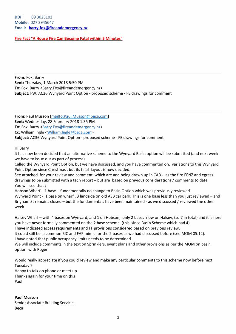
2
DDI: 09 3025101
Mobile: 027 2945647
Email: [email protected]
Fire Fact “A House Fire Can Become Fatal within 5 Minutes”
From: Fox, Barry
Sent: Thursday, 1 March 2018 5:50 PM
To: Fox, Barry <[email protected]>
Subject: FW: AC36 Wynyard Point Option - proposed scheme - FE drawings for comment
From: Paul Musson [mailto:[email protected]]
Sent: Wednesday, 28 February 2018 1:35 PM
To: Fox, Barry <[email protected]>
Cc: William Ingle <[email protected]>
Subject: AC36 Wynyard Point Option - proposed scheme - FE drawings for comment
Hi Barry
It has now been decided that an alternative scheme to the Wynyard Basin option will be submitted (and next week
we have to issue out as part of process)
Called the Wynyard Point Option, but we have discussed, and you have commented on, variations to this Wynyard
Point Option since Christmas , but its final layout is now decided.
See attached for your review and comment, which are and being drawn up in CAD - as the fire FENZ and egress
drawings to be submitted with a tech report – but are based on previous considerations / comments to date
You will see that :
Hobson Wharf – 1 base - fundamentally no change to Basin Option which was previously reviewed
Wynyard Point - 1 base on wharf , 3 landside on old ASB car park. This is one base less than you just reviewed – and
Brigham St remains closed – but the fundamentals have been maintained - as we discussed / reviewed the other
week
Halsey Wharf – with 4 bases on Wynyard, and 1 on Hobson, only 2 bases now on Halsey, (so 7 in total) and it is here
you have never formally commented on the 2 base scheme (this since Basin Scheme which had 4)
I have indicated access requirements and FF provisions considered based on previous review.
It could still be a common BIC and FAP mimic for the 2 bases as we had discussed before (see MOM 05.12).
I have noted that public occupancy limits needs to be determined.
We will include comments in the text on Sprinklers, event plans and other provisions as per the MOM on basin
option with Roger
Would really appreciate if you could review and make any particular comments to this scheme now before next
Tuesday ?
Happy to talk on phone or meet up
Thanks again for your time on this
Paul
Paul Musson
Senior Associate Building Services
Beca
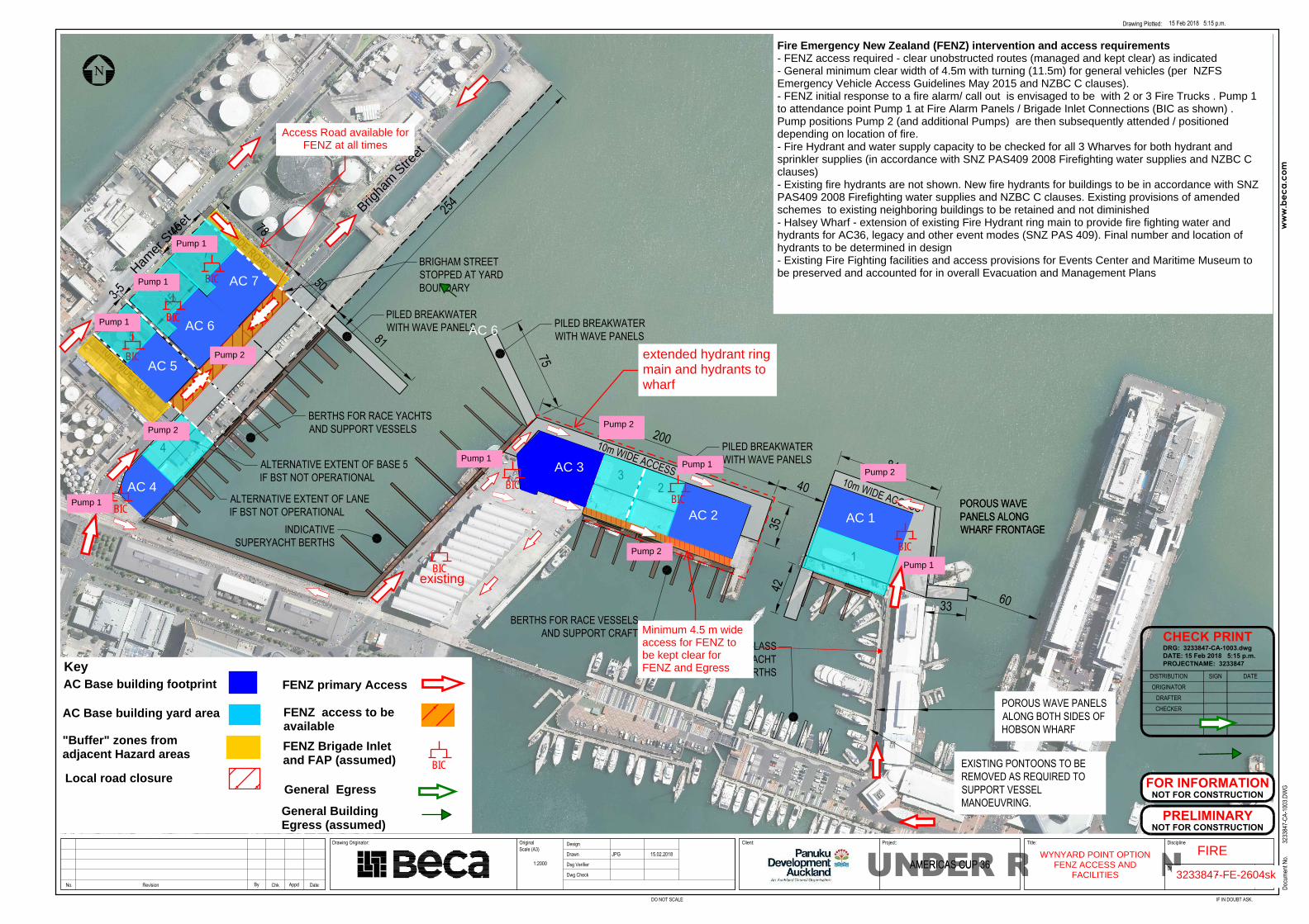
3233847-CA-XXXX *LAYOUT B
WYNYARD POINT
CIVILAMERICAS CUP 361:2000
JPG 15.02.2018
ww
w.b
eca.
com
CHECKER
CHECK PRINT
DISTRIBUTION
DRAFTERORIGINATOR
DATESIGN
DRG: 3233847-CA-1003.dwg
DATE: 15 Feb 2018 5:15 p.m.
PROJECTNAME: 3233847
UNDER REVISIONDrawing Originator:
Drawing Plotted:
Rev.
Docu
ment
No.
Discipline
Drawing No.
Title:
IF IN DOUBT ASK.
Project:Client:DesignOriginal
Drawn
Dsg Verifier
Dwg Check
Scale (A3)
DO NOT SCALE
DateChkByRevision AppdNo.
15 Feb 2018 5:15 p.m.
3233
847-
CA-1
003.D
WG
AMERICAS CUP 36
N
PILED BREAKWATERWITH WAVE PANELS
10m WIDE ROAD BRIGHAM STREETSTOPPED AT YARDBOUNDARY
FOR INFORMATION
NOT FOR CONSTRUCTION
NOT FOR CONSTRUCTION
PRELIMINARY
PILED BREAKWATERWITH WAVE PANELS
10m WIDE ROAD
PILED BREAKWATERWITH WAVE PANELS
NEW WHARF STRUCTURE
LEGEND
DENOTES PAVED YARD ORACCESS ROAD
NOTES AND ASSUMPTIONS
EXISTING WHARVES MAY REQUIRE STRENGTHENINGTO ACCOMMODATE MOBILE/TOWER CRANE LOADS
BUILDING FOOTPRINT
SYNDICATE BASE BOUNDARY
FLOATING PONTOON
BERTHS FOR RACE VESSELSAND SUPPORT CRAFT
BERTHS FOR RACE YACHTSAND SUPPORT VESSELS
ALTERNATIVE EXTENT OF BASE 5IF BST NOT OPERATIONAL
ALTERNATIVE EXTENT OF LANEIF BST NOT OPERATIONAL
200
8440
3575
81
254
42
33 60
J-CLASSYACHT
BERTHS
INDICATIVESUPERYACHT BERTHS
1
10m WIDE ACCESS10m WIDE ACCESS
POROUS WAVE PANELSALONG BOTH SIDES OFHOBSON WHARF
POROUS WAVEPANELS ALONGWHARF FRONTAGE
POROUS WAVEPANELS ALONGWHARF FRONTAGE
EXISTING PONTOONS TO BEREMOVED AS REQUIRED TOSUPPORT VESSELMANOEUVRING.
23
4
5
6
7
45
3-5
78
50
45 45
AC 4
AC 6
AC 3
Key
AC Base building yard area
AC Base building footprint FENZ primary Access
General Egress
General BuildingEgress (assumed)
"Buffer" zones fromadjacent Hazard areas
Brigha
m S
treet
Local road closure
Access Road available forFENZ at all times
Hamer
Stre
et
AC 5
AC 6
AC 7
AC 2 AC 1
FIRE
3233847-FE-2604sk
WYNYARD POINT OPTIONFENZ ACCESS AND
FACILITIES
BICFENZ Brigade Inletand FAP (assumed)
FENZ access to beavailable
BIC
BIC
BIC
BIC
BIC
BIC
BIC
existing
Fire Emergency New Zealand (FENZ) intervention and access requirements - FENZ access required - clear unobstructed routes (managed and kept clear) as indicated - General minimum clear width of 4.5m with turning (11.5m) for general vehicles (per NZFSEmergency Vehicle Access Guidelines May 2015 and NZBC C clauses).- FENZ initial response to a fire alarm/ call out is envisaged to be with 2 or 3 Fire Trucks . Pump 1to attendance point Pump 1 at Fire Alarm Panels / Brigade Inlet Connections (BIC as shown) .Pump positions Pump 2 (and additional Pumps) are then subsequently attended / positioneddepending on location of fire.- Fire Hydrant and water supply capacity to be checked for all 3 Wharves for both hydrant andsprinkler supplies (in accordance with SNZ PAS409 2008 Firefighting water supplies and NZBC Cclauses)- Existing fire hydrants are not shown. New fire hydrants for buildings to be in accordance with SNZPAS409 2008 Firefighting water supplies and NZBC C clauses. Existing provisions of amendedschemes to existing neighboring buildings to be retained and not diminished - Halsey Wharf - extension of existing Fire Hydrant ring main to provide fire fighting water andhydrants for AC36, legacy and other event modes (SNZ PAS 409). Final number and location ofhydrants to be determined in design - Existing Fire Fighting facilities and access provisions for Events Center and Maritime Museum tobe preserved and accounted for in overall Evacuation and Management Plans
BIC
Pump 1
Pump 1
Pump 2
Pump 1
Pump 1
Pump 1
Pump 2
Pump 2
Pump 1
extended hydrant ringmain and hydrants towharf
Pump 2
Pump 2
Pump 1
Minimum 4.5 m wideaccess for FENZ tobe kept clear forFENZ and Egress
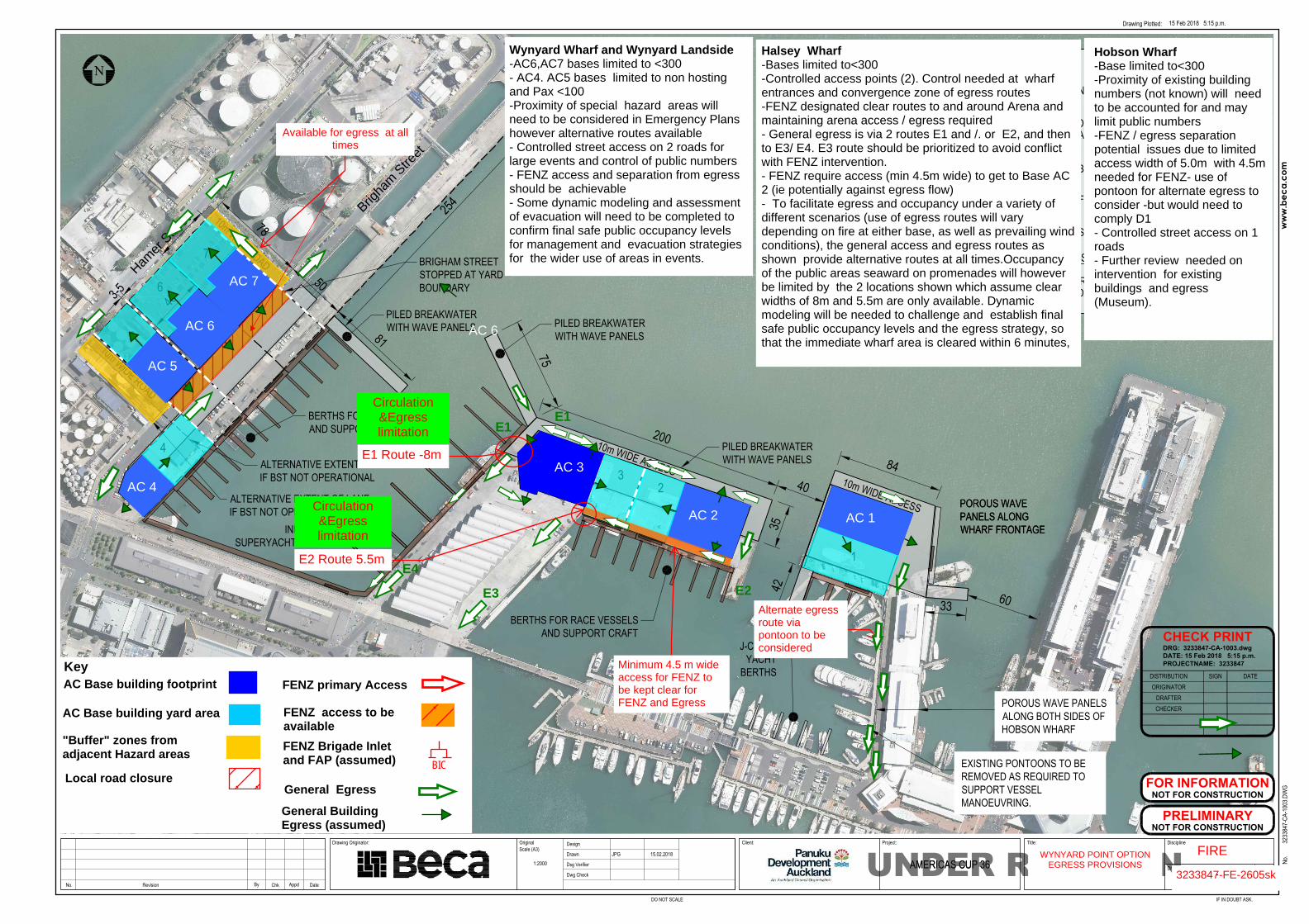
3233847-CA-XXXX *LAYOUT B
WYNYARD POINT
CIVILAMERICAS CUP 361:2000
JPG 15.02.2018
ww
w.b
eca.
com
CHECKER
CHECK PRINT
DISTRIBUTION
DRAFTERORIGINATOR
DATESIGN
DRG: 3233847-CA-1003.dwg
DATE: 15 Feb 2018 5:15 p.m.
PROJECTNAME: 3233847
UNDER REVISIONDrawing Originator:
Drawing Plotted:
Rev.
Docu
ment
No.
Discipline
Drawing No.
Title:
IF IN DOUBT ASK.
Project:Client:DesignOriginal
Drawn
Dsg Verifier
Dwg Check
Scale (A3)
DO NOT SCALE
DateChkByRevision AppdNo.
15 Feb 2018 5:15 p.m.
3233
847-
CA-1
003.D
WG
AMERICAS CUP 36
N
PILED BREAKWATERWITH WAVE PANELS
10m WIDE ROAD BRIGHAM STREETSTOPPED AT YARDBOUNDARY
FOR INFORMATION
NOT FOR CONSTRUCTION
NOT FOR CONSTRUCTION
PRELIMINARY
PILED BREAKWATERWITH WAVE PANELS
10m WIDE ROAD
PILED BREAKWATERWITH WAVE PANELS
NEW WHARF STRUCTURE
LEGEND
DENOTES PAVED YARD ORACCESS ROAD
NOTES AND ASSUMPTIONS
EXISTING WHARVES MAY REQUIRE STRENGTHENINGTO ACCOMMODATE MOBILE/TOWER CRANE LOADS
BUILDING FOOTPRINT
SYNDICATE BASE BOUNDARY
FLOATING PONTOON
BERTHS FOR RACE VESSELSAND SUPPORT CRAFT
BERTHS FOR RACE YACHTSAND SUPPORT VESSELS
ALTERNATIVE EXTENT OF BASE 5IF BST NOT OPERATIONAL
ALTERNATIVE EXTENT OF LANEIF BST NOT OPERATIONAL
200
8440
3575
81
254
42
33 60
J-CLASSYACHT
BERTHS
INDICATIVESUPERYACHT BERTHS
1
10m WIDE ACCESS10m WIDE ACCESS
POROUS WAVE PANELSALONG BOTH SIDES OFHOBSON WHARF
POROUS WAVEPANELS ALONGWHARF FRONTAGE
POROUS WAVEPANELS ALONGWHARF FRONTAGE
EXISTING PONTOONS TO BEREMOVED AS REQUIRED TOSUPPORT VESSELMANOEUVRING.
23
4
5
6
7
45
3-5
78
50
45 45
AC 4
AC 6
AC 3
Key
AC Base building yard area
AC Base building footprint FENZ primary Access
General Egress
General BuildingEgress (assumed)
"Buffer" zones fromadjacent Hazard areas
Brigha
m S
treet
Local road closure
Available for egress at alltimes
Hamer
Stre
et
AC 5
AC 6
AC 7
AC 2 AC 1
FIRE
3233847-FE-2605sk
WYNYARD POINT OPTIONEGRESS PROVISIONS
BICFENZ Brigade Inletand FAP (assumed)
FENZ access to beavailable
Minimum 4.5 m wideaccess for FENZ tobe kept clear forFENZ and Egress
E1 Route -8m
Circulation&Egresslimitation
Alternate egressroute via pontoon to beconsidered
Wynyard Wharf and Wynyard Landside-AC6,AC7 bases limited to <300- AC4. AC5 bases limited to non hostingand Pax <100-Proximity of special hazard areas willneed to be considered in Emergency Planshowever alternative routes available - Controlled street access on 2 roads forlarge events and control of public numbers- FENZ access and separation from egressshould be achievable- Some dynamic modeling and assessmentof evacuation will need to be completed toconfirm final safe public occupancy levelsfor management and evacuation strategiesfor the wider use of areas in events.
Circulation&Egresslimitation
E2 Route 5.5m
Halsey Wharf-Bases limited to<300-Controlled access points (2). Control needed at wharfentrances and convergence zone of egress routes-FENZ designated clear routes to and around Arena andmaintaining arena access / egress required- General egress is via 2 routes E1 and /. or E2, and thento E3/ E4. E3 route should be prioritized to avoid conflictwith FENZ intervention.- FENZ require access (min 4.5m wide) to get to Base AC2 (ie potentially against egress flow)- To facilitate egress and occupancy under a variety ofdifferent scenarios (use of egress routes will varydepending on fire at either base, as well as prevailing windconditions), the general access and egress routes asshown provide alternative routes at all times.Occupancyof the public areas seaward on promenades will howeverbe limited by the 2 locations shown which assume clearwidths of 8m and 5.5m are only available. Dynamicmodeling will be needed to challenge and establish finalsafe public occupancy levels and the egress strategy, sothat the immediate wharf area is cleared within 6 minutes,
Hobson Wharf-Base limited to<300-Proximity of existing buildingnumbers (not known) will needto be accounted for and maylimit public numbers-FENZ / egress separationpotential issues due to limitedaccess width of 5.0m with 4.5mneeded for FENZ- use of pontoon for alternate egress toconsider -but would need tocomply D1- Controlled street access on 1roads- Further review needed onintervention for existingbuildings and egress(Museum).
E1
E2
E1
E3
E4
1
Paul Musson
From: Fox, Barry <[email protected]>
Sent: Thursday, 15 February 2018 5:27 p.m.
To: Paul Musson
Cc: Twomey, Richard
Subject: RE: Americas World Cup AC36 - Wynyard Point Option
Attachments: AC 36.docx
Paul
Thanks for your update on the Wynyard Point Option.
Comment are as follows:
• As stated in previous correspondence, the removal of Stolthaven South complex is the preferred option for
Fire and Emergency NZ.
• Maintaining an emergency access corridor (gated) for our fire appliances along Brigham St is acceptable to
our operations.
• Buffer Zones shown at the sides of the AC bases are engineered to an appropriate size for the perceived risk.
• The one way access road through the Buffer Zone on the north-eastern side of AC base 7 provides us with an
acceptable alternative access route to the northern end of Wynyard Point risks.
• All other comments made in the attached document relating to the Wynyard Point options (dated 23rd Jan
2018), remain valid.
Fire and Emergency NZ are keen to work with the scheme proponent on whatever option is selected to mitigate risk.
This latest update on the “Wynyard Point” option is the most suitable option to date of those proposed for AC bases
in this area.
Please contact me if you wish to discuss this further.
Let me know if the planned meeting next week is still required.
Regards
Barry
Barry Fox MIFireE
Assistant Area Commander
Area 4, Auckland City Fire Area
40 Pitt Street, Newton, Auckland 1010
PO Box 68646, Wellesley Street, Auckland 1141
DDI: 09 3025101
Mobile: 027 2945647
Email: [email protected]
Fire Fact “A House Fire Can Become Fatal within 5 Minutes”
2
m: Paul Musson [mailto:[email protected]]
Sent: Thursday, 15 February 2018 4:10 PM
To: Fox, Barry <[email protected]>
Cc: William Ingle <[email protected]>
Subject: RE: Americas World Cup AC36 - Wynyard Point Option
Barry
Updated Drawing
Paul
From: Paul Musson
Sent: Thursday, 15 February 2018 1:51 p.m.
To: '[email protected]' <[email protected]>
Cc: William Ingle <[email protected]>
Subject: RE: Americas World Cup AC36 - Wynyard Point Option
Sorry Barry
Will send up date – but Bingham will be closed – but allow FENZ access through bases via controlled gates
Paul
From: Paul Musson
Sent: Thursday, 15 February 2018 12:52 p.m.
To: '[email protected]' <[email protected]>
Cc: William Ingle <[email protected]>
Subject: Americas World Cup AC36 - Wynyard Point Option
Hi Barry
As we briefly discussed, an alternative option is now on the table for the Wynyard Point configuration which we
need to conclude assessment by mid next week
See attached
I have also included a mark-up (by Beca) on the considerations for these (FE-1003)
• Stolthaven haz tanks are removed and the land reused, with ASB, car park for 3 bases
• Buffer zones for remaining bulk fuel storage
• No high load public access on race / major days to Wynyard Point areas (controlled)
• Access road between Hamer and Brigham
• Brigham open, but access will need to be locally stopped /managed whilst boats go yard to water and back
• It remains that recommended all Sprinklered buildings
• It remains comments made on emergency plans etc
Any additional comments to this scheme welcome – we have pencilled in meet next week but if you comment prior
and don’t see the need to catch up let me know
Paul Musson
Senior Associate Building Services
Beca
Phone: +64 9 300 9317 Mob: +64 27 215 6443
www.beca.com
igniteyourthinking.beca.com
AC 36-Wynard Point Options.
23rd January 2018
Fire and Emergency New Zealand Comments on proposals
Requested by Ms Hannah Keats – Senior Advisor, MBIE
Initial high level comments the Wynyard Point proposal provided by our National Operations
Manager – Paul Turner remain valid.
The Wynyard Point options requiring comment will result in Americas Cup (AC) base buildings being
located in three distinct areas:
• Halsey Street Extension Wharf
• Extension to Hobson Wharf
• And Wynyard Wharf/Point area (partial closure of Brigham Street)
Key considerations for Fire and Emergency are
Access
One of our primary concerns with this proposal is the reduction in access for our fire appliances
along Brigham Street to the northern end of Wynyard Point. This road provides Fire and Emergency
NZ staff with an alternative safe access route if we are required to manage an incident (fire, spill or
leak) in this tank farm area.
The proposal of the two way “link Road” between Hamer Street and Brigham Street between the
tank farm and the proposed AC Base 5 will provide us with a viable alternative option to the
northern end of Wynyard Point via Brigham Street.
This link road could potentially be compromised if we had a bulk flammable liquid fire near this road
with an unfavourable wind direction, (nor-easterly). If presented with these variables, we may need
to utilise an emergency access corridor through the hard stand areas of the proposed AC bases.
Any delays to our fire attacks in the tank farm area could potentially result in an increased impact on
the AC 36 event, environmental contamination (air and sea), higher level of disruption to the public
and general operations associated with this area.
Evacuation Strategies
An overall evacuation strategy for the combined site needs to be developed should a mass
evacuation be required for the overall AC 36 Village.
With this Wynyard Point proposal, I have been advised, the AC base buildings will have the ability to
cater for functions and other activities hosting up to 300 people at one time. Considering the risk
profile detailed in the ‘Sherpa Report”, careful consideration must be given to the number of people
and the activities these buildings will be used for.
The evacuation strategies for individual buildings should be developed to include two independent
egress pathways from the structures to the assembly areas. This provides flexibility for evacuation
of depending on the location and variables associated with the given emergency.
Building protection
As part of the risk mitigation for the structures, we strongly recommend the AC 36 Bases be sprinkler
protected structures and the system be designed and installed to the appropriate risk profile.
The sprinkler protection will minimise the damage to:
• The structure and help keep the fire isolated to building of origin
• Assist with the providing safer egress of occupants from the structure
• Minimise the impact on the AC 36 event
• Reduce the risk of fire spread and impact on neighbouring businesses.
Automatic Fire detection system should also be included in these buildings to provide early warning
of a fire for occupants.
Firefighting Water:
Available water for firefighting should be to up to the level detailed in the Code of Practices for
Firefighting Waters Supplies. Alternative options for firefighting water supplies can be discussed with
Fire and Emergency rep should this be required.
Risk Mitigation – Stolthaven South Operation.
Stolthaven South handles flammable liquids and low toxicity materials. The proposal to relocate this
operation to another site eliminates any risk posed from this site to the AC base structures and the
personnel operating in that area. Fire and Emergency NZ support this relocation option.
Should the relocation of Stolthaven South operation not be adopted, additional risk mitigation
options may be included in the AC 36 Base designs, people management processes, and surrounding
operations that will reduce the risk.
Fire and Emergency NZ will work with either option.
The remaining bulk flammable liquid storage facilities at this location should review their firefighting
infrastructure to ensure their facilities meets the “Industry best practice”.
Summary: Wynyard point options
• Fire and Emergency NZ are agreeable to the proposed two way link road between Hamer
and Brigham Streets as a workable solution for Emergency Vehicle accessing the northern
end of Wynyard point via Brigham Street.
• Firefighting water supplies are as per the Code of Practice.
• Appropriate evacuation strategies are developed for the AC Bases and the overall venue.
• We support the relocation of Stolthaven, but will work with the alternative if that is the
preferred option.
• The inclusion of the one way private link road on the Stolthaven south site could be useful
to emergency services operations given an incident in that area.
• Appropriate fire protection / detection systems be included in the AC base structures.
Fire and Emergency NZ are keen to work with the scheme proponent on whatever option is selected
to mitigate risk and address issues.
Reference: “Sherpa Report” – Developed for Panuku Development Auckland, 08 Jan 2018
Beca // 5 December 2017 // Page 1
3233847 // NZ1-14924215-10 0.10
Minutes of Meeting
America’s Cup 36: Fire and Emergency New Zealand, Beca, Barker & Associates Meeting
Held 5th of December 2017 at 12:30pm
at Beca Office 21 Pitt St, Auckland.
Present: Roger Callister (RC)
Paul Musson (PM)
Joe Greene (JG)
Jennifer Hart (JH)
Lara Clarke (LC)
Fire and Emergency New Zealand (FENZ)
Beca
Beca
Beca
Barker & Associates
Apologies: Guy Dawson Beca
Distribution: As above plus Matthew Twose
Vijay Lala
Nick Roberts
Will Ingle, Stephen Priestley, Martin
Peat, Joe Phillips, Kara Hartshorne
Panuku Development Auckland
Tattico
Barker & Associates
Beca
Item Action
1 Introductions
Introduction by Beca to the project, concept design and structural form, base layouts and agenda for the meeting.
A 3D visualisation of the proposed infrastructure (created by others) was viewed and discussed.
2 AC36 Concept
Beca tabled the latest concept design layout sketches showing the location of syndicate bases, relocated ferry and fishing fleet facilities and the proposed structures.
Three distinct areas of interest were identified by Beca:
1. Extension to Halsey Street Extension Wharf (HSEW)/ Western Viaduct Wharf;
2. Extension to Hobson Wharf;
3. Infill of sections of Wynyard Wharf South.
Layout, approximate geometry, structural form and timings were discussed.
Beca advised that the Emirates Team New Zealand (ETNZ) base on Hobson Wharf extension is the only base which would likely be permanent, with the others remaining in place for up to four years (should the 2021 defence be successful).
Beca also advised that hospitality events are anticipated at the (ETNZ) base on Hobson Wharf extension during the America’s Cup (AC) event.
It was noted that there are limited details currently available for syndicate base buildings, but it is anticipated that they are approx. 15m high, probably with more than one floor, most likely through inclusion of a mezzanine level.
Beca // 5 December 2017 // Page 2
3233847 // NZ1-14924215-10 0.10
3 Ambitions
Beca outlined a few key project ambitions, including:
1. Public access to the north face of the extended Halsey Street Extension Wharf / Western Viaduct Wharf and breakwater structures, for spectating;
2. Public access provided to the existing North Wharf, Karanga Plaza, Te Wero Island, Eastern Viaduct and Princes Wharf for spectating.
4 Firefighting at Syndicate Bases
Buildings on syndicate bases are effectively permanent from FENZ perspective.
RC made a strong recommendation for the syndicate base buildings to be provided with sprinkler systems, or high pressure misting systems due to the nature of the operations envisaged within syndicate base buildings, presence of flammable liquids and solvents, and burning characteristics of carbon fibre (significant amounts of which will be present in the bases). Once alight, carbon fibre burns well and produces dark, toxic smoke. As well as the inhalation risks, this can make visibility a problem when fighting the fire.
In addition to this, RC noted that there should be more than one evacuation point such that crowding down-wind of the smoke is avoided.
Due to the operations and materials noted above, in the syndicate bases, RC advised that sprinkler system design will likely require a high density of sprinklers, however they will reduce the peak firefighting flows required from the water network if compared to design for structures without sprinkler systems. A high pressure mist system would reduce the burden on the water network further, but with a higher capital cost.
RC advised that if sprinkler/mist systems are provided for one base, they should be provided for all, mindful of avoid liability issues for the race organisers and infrastructure owners and redundancy of sprinkler systems if adjacent buildings develop a significant fire.
It was noted by RC that the sprinkler system could be common throughout the bases, or zoned for each syndicate base. However, the smoke detectors should be zoned. Fire alarm panels were discussed and RC advised that individual panels or separation of alarm systems would be of benefit in determining in which base the fire has broken out. In the absence of this approach, emergency services arriving at the location would not know initially, in which syndicate base the alarm was activated.
RC also advised that a manual system whereby reliance is placed upon personnel activating the alarm, should be avoided where possible.
A main (repeater) panel in the area of the existing Viaduct Events Centre for bases 2-5 was discussed and agreed to be a sensible option.
Base 1 would have its own fire alarm panel, as would bases 6-8.
Separation (passive fire protection) of the syndicate bases was discussed, and the related building consent requirements. However, this is to be considered in more detail once the design progresses further, and syndicate buildings better defined.
For the syndicate bases on the extended Halsey Street Extension Wharf / New Western Viaduct Wharf, RC advised that 3 fire appliances would arrive in approximately 3 minutes to respond to the fire alarm. If the presence of a fire is confirmed, another 3 appliances would then be summoned. RC outlined the locations of the first, second and third appliances as likely being :
1. North of the Viaduct Events Centre, perhaps at the location of the main
Beca // 5 December 2017 // Page 3
3233847 // NZ1-14924215-10 0.10
(repeater) firefighting alarm panel (which would be of benefit);
2. On the south side of the Western Viaduct Wharf;
3. On the north side of the Halsey St Extension Wharf extension.
Appliance locations for syndicate base 1 on extended Hobson Wharf - 1 appliance on south side, 1 on north side. Similar approach for bases 6-8.
An over-arching Rapid Response Team (RRT) with responsibility for all the syndicate bases and wider AC event was recommended by RC. This would have a number of benefits for compliance with fire procedures (eg functioning of auto-opening gates) and general safety and security, and could be implemented once number of operational bases starts into increase – say 3+ bases operating.
It was noted that the RRT could be an extension of that which manages the fire risk for the silo/tank areas on Wynyard Point.
RC inquired if there is a sprinkler system in the maritime museum. Beca to investigate.
Beca
5 Access and Egress
Beca noted that syndicate bases and yards are secure facilities, and contents are sensitive, thus are not accessible to the general public.
RC raised the issue of crane operations during emergency. It was agreed that there should be a system in place whereby crane lifts are aborted at the sound of a fire alarm, with vessels returned to the water quickly and access routes made free from obstacles.
Mast laydown was discussed in relation to obstacles for fire appliances. It was noted by Beca that the mast was expected to accommodate this (Beca to confirm).
Access and egress was discussed in detail for syndicate bases on the Halsey and Hobson Wharf extensions :
A route was identified by RC to gain access to the northern side of the syndicate bases on the Halsey Wharf extension, via a marked corridor along the 8m wide access road. RC questioned the ability of fire appliances to turn this corner and noted that if sufficient space is provided, the fire appliances could also do a 3 point turn. The building corners could potentially be chamfered to accommodate this. Beca to check the swept path of a fire appliance turning this corner and 3 point turn and confirm.
RC noted that preferably the fire appliance would drive out forwards, via the 4.5m accessway further east.
Automated electronic gates (opening on fire alarm activation) would be required on bases 2-4 for fire appliance access and pedestrian egress.
It was agreed that the secondary egress (and egress only) routes would be utilised on the east of side of Halsey 4.5m and 2m.
Egress for pedestrians was identified as being via a marked corridor through the 8m access road, both accessways (2m and 4.5m) to the east, and (gated) emergency egress through base 2-4 (from 2m and 4.5m accessways), and base 5 (from breakwater and north face). This could be via automated electronic gates which open when the fire alarm sounds.
It was noted that when the AC race is in progress, the greatest crowding takes place, but is accompanied by a reduced fire risk due to the operations within the syndicate bases being reduced. Conversely, when the highest fire risk is present (most frequent and highest fire risk
Beca – ASAP
Beca // 5 December 2017 // Page 4
3233847 // NZ1-14924215-10 0.10
activities in the syndicate bases – night time repairs), the anticipated number of general public on the wharves are reduced.
A turning circle location for fire appliances on Hobson Wharf extension was identified to the east of the syndicate base. Swept path to be checked by Beca.
Secondary egress from the Hobson Wharf extension was discussed by means of gangway access to the existing pontoons. This was agreed to be a potential back-up egress route.
Access and egress to the syndicate bases on Wynyard Wharf was noted to be much less restricted, with wide corridors available between buildings. However, a traffic management system will be required to facilitate egress of the public across the road as there is no footpath on the eastern of Brigham St. A RRT would be helpful for implementing this emergency traffic management.
RC questioned the structural capacity of North Wharf, Western Viaduct Wharf, Hobson Wharf and Wynyard Wharf for loading from fire appliances. Beca to investigate. Also review the potenital access route along the reclamation landward of North Wharf for accessing fires on yachts moored at North Wharf.
The operation of the Viaduct Events Centre (VEC) during the AC event was questioned by RC. Beca noted that it would likely be used for race organisation and media etc. Cabling, generators and parked vehicles would impede fire access. Measures will be required to control this such as hatched ‘no stopping’ areas on each side of the VEC, along with specific areas for storage of generators on the north or south side of the VEC.
Beca - ASAP
6 Water Supply to Firefighting
RC advised new pump houses would be required for the sprinkler systems, and that firefighting inlets to be positioned at or near pump houses.
RC also noted that fire hydrants must remain available and accessible during every stage of the event, and under no means be obstructed by AC activities.
Existing hydrants on north face of existing HSEW will remain. Additional hydrants on the north face of the new HSEW extension are required, supplied by a ring main around the existing and new Halsey St/ Western Viaduct Wharves.
Droppers to harbour for seawater firefighting were discussed. RC noted that these are not a preferred option as there are associated maintenance issues with such systems, due to the rapid (within a few months) accretion of marine growth in the dropper pipe which blocks it, compromising its use.
RC inquired about the condition of the existing dropper pipes on Queens Wharf, and gave a contact name at the Wharf.
FENZ are in possession of a 2km hose carrier and as such could utilise water from the tank farm hydrants in Wynyard Quarter if need be. However, this asset is for contingency use and should not be considered as a design relief.
Marine vessel-based firefighting was raised by LC and discussed. Unlike in the previous AC event, no specific vessels are currently readily available to the FENZ. However, it is anticipated that services such as the police / coastguard / Department of Conservation could provide vessels to transport firefighting personnel if needed.
Beca to check
Minuted by: Joe Greene

Australia
Fiji
Indonesia
Myanmar
New Caledonia
New Zealand
Singapore
Thailand