Embed Size (px)
Citation preview

Contents lists available at ScienceDirect
Renewable and Sustainable Energy Reviews
journal homepage: www.elsevier.com/locate/rser
A review on boilers energy use, energy savings, and emissions reductions
M.C. Barmaa, R. Saidurb,c,⁎, S.M.A. Rahmand, A. Allouhie, B.A. Akashf, Sadiq M. Saitg
a Department of Mechanical Engineering, University of Malaya, 50603 Kuala Lumpur, Malaysiab Research Centre for Nano-Materials and Energy Technology (RCNMET), School of Science and Technology, Sunway University, No. 5, Jalan Universiti,Bandar Sunway, 47500, Petaling Jaya, Malaysiac Center of Research Excellence in Renewable Energy (CoRE-RE), Research Institute, King Fahd University of Petroleum and Minerals (KFUPM), SaudiArabiad Sustainable and Renewable Energy Engineering, University of Sharjah, University City, 27272, Sharjah, United Arab Emiratese École Supérieure de Technologie de Fès, USMBA, Fès, Moroccof Department of Mechanical Engineering, American University of Ras Al Khaimah, United Arab Emiratesg Center for Communications and IT Research, Research Institute, King Fahd University of Petroleum and Minerals (KFUPM), Saudi Arabia
A R T I C L E I N F O
Keywords:BoilerEnergy savingsEmission analysisLossess in boiler
A B S T R A C T
Boiler is a widely used steam generating system in industries and power plants. A significant portion of theworld energy consumption is being used in boilers. A small improvement on the boiler efficiency will help tosave a large amount of fossil fuels and to reduce CO2 emission. This study describes the amount of energy usedin boilers, ways employed to evaluate their energy efficiency, losses occurred and their causes, ways of wasteheat recovery and minimizing heat loss using technologies, role of maintenance activities, and technicaleducation to make people aware of the energy usage. Latest published literature on the above mentioned topicswhich includes PhD and MSc theses, journal articles, conference proceedings, reports and web materials havebeen reviewed and reported. It is found that a substantial amount of energy is wasted through high temperatureflue gas or exhaust of the boiler. Also, some other unavoidable losses occurr due to various reasons. However,waste heat could be recovered using different technologies as a useful form of energy such as electricity, heat,refrigeration effect, etc. The efficiency of the boiler can be improved by doing scheduled maintenance work,which helps to run a boiler at its highest efficiency. In order to create awareness about energy use, educationprograms and seminars need to be arranged on regular basis for the staff involved. This will help them tounderstand the importance of the energy as being used in the boiler system as well as the impact of their actionsduring the operation of the boiler.
1. Introduction
Boilers are pressure vessels used for heating water or producingsteam to provide heating facility in industries and to generateelectricity through driving steam turbines. Boilers are also used forproviding space heating for buildings as well as for producing hot waterand steam required by users such as laundries and kitchens [1]. Fossilfuels such as coal, gas, oil etc., and nuclear energy, are being used togenerate a major portion of world's electricity and generally boilers arethe best choice to convert these types of energy into electricity [2,3].Hence, it is obvious that enhancement of the efficiency of a steam boilerby just a small fraction, will reduce a vast amount of energy consump-tion in electricity generation. Again, despite the depletion of fossil fuelreserves and environment protection issues, the oil, natural gas andcoal demand is expected to rise up to 47.5%, 91.6%, and 94.7%,
respectively between 2003 and 2030 [4]. Moreover, most of theindustrial heating systems employ boilers to produce hot water orsteam. Therefore, an efficient boiler has also a significant influence onheating-related energy savings [5]. A substantial amount of energy canbe saved by adopting energy saving measures and by improving theoverall boiler efficiency.
In the combustion chamber of a boiler, fossil fuel burnt and theproduced heat is transferred through hot flue gas to water. As the hotflue gas transfers heat to water by convection heat transfer, a majorportion of heat is lost through the outgoing flue gas. As the temperatureof the flue gas leaving a boiler typically ranges from 150 to 250 °C,about 10–30% of the heat energy is lost through the process [6,7].Other heat losses from a boiler are radiation, blow-down, fly ash andbottom ash losses [8,9]. in order to run a boiler plant at its maximumefficiency, it is necessary to identify the major source of energy wastage
http://dx.doi.org/10.1016/j.rser.2017.05.187Received 12 March 2016; Received in revised form 8 May 2017; Accepted 21 May 2017
⁎ Corresponding author.E-mail addresses: [email protected], [email protected] (R. Saidur).
Renewable and Sustainable Energy Reviews 79 (2017) 970–983
1364-0321/ © 2017 Elsevier Ltd. All rights reserved.
MARK

and recover the energy which is wasted.The efficiency of boiler is the ratio of the net amount of heat which
is being absorbed by the generated steam to the net amount of heatsupplied to the boiler. This can also be determined by subtracting thenet amount heat lost from the boiler from the net amount of heatsupplied to the boiler [10]. Hence to improve the boiler efficiency, theamount of heat being wasted from the boiler needs to be minimized byoptimizing some parameters such as excess air, fuel flow rate, steamdemand, etc. [11]. To ensure complete combustion, a boiler is to beprovided with more combustion air than what is theoretically sug-gested. Otherwise, there will be a rapid buildup of carbon monoxide inthe flue gas, and in extreme cases, smoke will be produced. On theother hand, too much excess air increases the quantity of unnecessaryair that is heated and exhausted at the stack temperature [12]. A typicalheat balance in a boiler is shown in Fig. 1.
According to Fig. 1, 10–30% of the input heat is wasted through theflue gas and this is the highest source of heat loss in the boiler system.Since most of the heat is being wasted through the high temperatureflue gas, the recovery of heat from high temperature exhaust can resultin significant energy savings [1,13,14]. Harnessing the waste heat fromthe high temperature flue gas could be a huge energy savings potentialfor a boiler system. However, the boiler efficiency can be improved byminimizing this loss supplying optimizing excess air ratio using a VSD(variable speed drive) [15–17]. A VSD is used on the fan motor tochange excess air ratio. Fig. 2 shows boiler efficiency with the flue gastemperature reduction.
Fossil fuel consumption is directly related to the emission of CO2.Environmental protection regulations insist to reduce the emission ofCO2 [19–21] as this is significantly responsible for the greenhouseeffect. Hence, to reduce the emission of CO2 and consumption of fossilfuels, the efficiency of the current energy systems must be improved.There are many ways to reduce energy and heat consumption andcarbon dioxide emissions [21–23]. Thermal efficiency of the powerplant is around 30.12% for the gross generator output and themaximum energy loss occurs in the boiler. As a result, the performanceof the power plant could be greatly improved by improving theperformance of the boiler, since this will contribute to the largestimprovement to the plant's efficiency [24].
From the literature, there is no comprehensive review on energyuse, savings, associated bill savings and avoided emission, along withcost benefit analysis. It is expected that this study will fill that gap.Furthermore, the study could provide important guidelines for futureresearch and development allocations and energy projects to reduceboiler energy use. It will create awareness among the industrial energyusers to reduce the boilers energy uses along with environmentalpollution reduction.
2. Energy used in boilers
Most of the major industrial processes use steam. USA alone isconsuming and burning about 37% of the total fossil fuel to producesteam. This steam has been used in different processes such as heating,concentrating and distilling liquids, drying, etc. Major energy intensiveindustries allocate significant part of their primary fuel consumption tosteam generation: food processing (57%), paper and pulp (81%),petroleum refining (23%), chemicals (42%), and primary metals(10%) [9]. Saidur and Mekhilef [25] reported that 20% of total energyconsumption is used in process heating in a rubber producingindustries in Malaysia. Fig. 3 shows different types of energy consump-tion along with process heat in rubber industry in Malaysia. In 2012,U.S. electric utilities converted 38 billion GJen of coal, natural gas, andnuclear energy into 12.3 billion GJelec of electricity [26], an averageefficiency of 32%. Electricity generation at these plants is performed bycombustion fuel (e.g., coal and natural gas) or utilizing nuclearreactions to heat a fluid. The resulting hot fluid drives the blades of aturbine and its associated generator, thereby converting thermal energyinto mechanical energy and then electric energy [27–29].
To supply steam for a textile plant significant amount of energy isrequired. Fig. 4 shows energy consumption for generating steam andother types of final energy consumption in a textile plant in the U.S.The percentages may vary from one country to another, but this figuregives a hint of final energy end-use in the textile industry. In the U.S.textile industry motor-driven systems and steam generation systemshave the highest share of the end-use energy use and each accounts for28% of total final energy use [30].
3. Energy audit for boilers
Energy audit is a systematic approach to investigate industrial
Nomenclature
AAS Actual Air supply (kg)AF Air fuel ratio (kg/kg)AC Alternate Current (A)C CarbonCO Carbon mono oxideCO2 Carbon dioxideCp Specific heat of moisture (kJ/kgK)Cpg Combustion gas specific heat (kJ/kgK)EA Excess airGCV Gross Calorific Value (kJ/kg)H HydrogenHHV Higher heating value (kJ/kg)K ConstantLHV Lower Heating Value (kJ/kg)Lstack Energy loss through stack
M Mass of moisture in fuel (kg)ma Mass flow rate of air (kg)mf Mass flow rate of fuel (kg)mg Mass of combustion gas (kg)N NitrogenO2 Oxygenppm Parts per millionRTD Resistance Temperature DetectorTDS Total Dissolved SolidsTa Temperature of air (K)TC Combustion Temperature (K)Tf Temperature of fuel (K)Tstack Stack temperature (K)VFD Variable Frequency DriveVSD Variable Speed driveη Efficiency (%)
Fig. 1. Typical Heat Balance of a boiler [1].
M.C. Barma et al. Renewable and Sustainable Energy Reviews 79 (2017) 970–983
971

energy consumption and to exactly locate the sources of energywastage. This is a useful tool for an organization to analyze andunderstand its energy utilization. It also helps to decide on budgetedenergy distribution in different section of an organization, plan energyconsumption, which will improve their energy efficiency, curb energywastage, and, significantly reduce energy costs [31,32]. The energyconsumption cost is a major part of a production process cost and oftenforms a major cost of the plant. The energy audit serves to identify andquantify all the energy consumptions in a facility, in an attempt tobalance the total energy input with its use. Thus, energy audit can beused as a systematic method for policy making in the area of energymanagement. The energy audit study becomes an effective tool indefining and pursuing a comprehensive energy management program.A comprehensive review on types of energy audit, objectives, benefitand energy audit process is outlined by Saidur [31,33].
3.1. Tools for energy audit
Energy audit starts with a walk through visit and meetings withplant officials and interviewing of the site operators. Walk throughvisit, facility utility bills such as electricity gas and water etc., and otheroperating data help to become familiar with the building operation andto identify any glaring areas of energy waste or inefficiency. Utility billsfor a 12–36 month period are needed to allow the auditor to evaluatethe facility's energy demand rate structures and energy usage profiles.But for detailed energy audit, more detailed informations about facilityoperation are required. To collect information of the boiler operationfollowing tools are needed.
3.1.1. Flow meterTo measure wet, saturated, and superheated steam and water flow
accurately.
3.1.2. Exhaust gas analyzerTo measure the efficiency of combustion and the levels of different
pollutant gases as accurately as possible at the chimney of the boiler.
3.1.3. Pressure probeRequirement of pressure in boiler system varies from one place to
another to obtain the maximum combustion efficiency. Pressures aremeasured at various locations of a boiler using pressure probes, whichcan be used without interfering the normal operation of the boiler.
3.1.4. Clamp-on power meterTo measure power consumption, current consumption, load factor
and power factor by different electrically driven system clamp on powermeter can be used. The clamp-on feature of the meter enables to recordthe measurements without disrupting normal operation.
3.1.5. Portable tachometerPortable tachometer is useful for measuring the speed of any
rotating part of the boiler system. Optical type tachometers arepreferable due to the ease of measurement.
3.1.6. Thermocouple sensorThermometer/thermocouple sensors are used to measure tempera-
ture at different location. RTDs and thermistors are most commonlyused temperature measuring sensors. To store the data a data loggershould be connected to temperature sensors. Thermal image camera orinfrared thermometer also can be used to measure the temperature of aplace of the system which is not accessible for thermocouple sensors.
3.1.7. Data loggerDifferent types of parameter of the system are needed to collect for
longer periods of time. Data loggers are employed to record data suchas temperatures of different location of the boiler, power consumptionby motors, flue gas composition for a certain period of time. Measuringtape, slide calipers, etc., are needed to measure the dimensions ofboilers and steam pipes as well as other important parameters of thesystem. Some laboratory instruments are also needed to facilitate thedetermination of characteristic features of the fuel. Thermogravimetricanalysis, ultimate analysis, and heating value determination arecommonly used laboratory related work needed in energy audit.
A detailed financial analysis is also needed regarding the imple-mentation cost, operating cost savings, and the amount of investment.
4. Losses in boilers
The thermal efficiency of boilers producing superheated steam orheating thermal oil depends execusively on the amount of heat loss.The ways of heat loss varies depending on the type of fuel, type ofboiler, operating conditions, etc. Bujak et al. [34] reported that the heat
Fig. 2. Efficiency of a boiler with the flue gas temperature reduction [18].
Fig. 3. Energy used by process heat in rubber industries [25].
Fig. 4. Final Energy End-Use in the U.S. Textile Industry (U.S. DOE, 2004) [30].
M.C. Barma et al. Renewable and Sustainable Energy Reviews 79 (2017) 970–983
972
loss occurs in gaseous and oil fuels fired boilers through chimney,through the external surface of the boiler to the atmosphere, and due toincomplete combustion. Each boiler also loses heat due to technicaland operating conditions, which influences heat efficiency. Gupta et al.[35] reported that the sources of heat loss in coal fired boilers areunburnt carbon in refuse, dry flue gas, moisture in fuel, radiation, blowdown, and burning of hydrogen. Energy can be lost due to opencondensate tank [22,36]. Boilers energy efficiency varies from 20% to92% depending on the fuel type and purpose of the boiler [24].Thermal efficiency of coal fired boilers varies between 81% and 85%,for oil between 78% and 81% and for gas between 76% and 81%(HHV). Poor maintenance of boilers can lose up to 30% of the originalefficiency [37]. The major portion of heat loss occures due to high air/fuel ratios, steam generation under rated capacity, surface thermallosses, and high flue gas temperatures [38]. Heat losses occur in everysection of boiler system. All losses can be categorized into four broadcategories.
• Heat carried away by dry flue gasses (Excluding water vapor).
• Heat carried away by hot water vapor, including both sensible andlatent heat.
• Heat loss due to unburned carbon in fuel, incomplete combustion,conduction, radiation and convection losses from the outside sur-face.
• Blow-down loss [39].
4.1. Heat loss due to stack gas
The largest portion of energy loss in a boiler occurs through thestack gas. The temperature and volume of stack gas leaving the boilerare the main factors for the heat loss assessment. Therefore, reductionof any of these parameters will reduce the heat loss. To eliminate stackloss, the temperature of stack gas would have to be reduced to boilersurrounding temperature. But due to the economical infeasibility andlimitation in heat transfer principle these losses are unavoidable [8,39].Excessive flue gas may result from leaks in the boiler, excess air supplydue to high frequency of forced draft fan and leaks in the flue gas duct,which is responsible for reduction on heat transfer to the steam andincrease in pumping requirements [30,37]. Stack gas heat loss can beminimized by taking following measures:
• Excess air optimization
• Maintaining clean heat transfer area
• Addition of flue gas heat recovery systems
The volume of stack gas is reduced because of less excess air. Thus,the flue gas velocity decreases due to lower volume of stack gasallowing more time for absorbing heat from flue gas and temperatureof flue gas would be lowered. In general, the efficiency of boilers variesfrom 75% to 90%, so ways should be sought to minimize the resulting10–25% energy losses in boilers [40].
4.2. Conduction and radiation losses
There is a temperature difference between boilers outer surface,auxiliary equipment, and distribution piping of steam and the sur-rounding areas. Therefore, heat loss occurs by radiation, convectionand conduction from the hot surfaces of the boiler systems. Theamount of heat lost depends on the temperature of the hot surface,which in turn depends on the insulation (thickness, thermal conduc-tivity, and condition). To minimize that heat loss, hot surfaces shouldbe covered with insulation material having sufficient resistance to heattransfer [35]. Furthermore, the insulation should be of adequatethickness and it should be in good condition. Also, heat loss dependson the area of the hot surface. Since boilers have large surface areas,heat loss from the boiler by radiation can be significant while operating
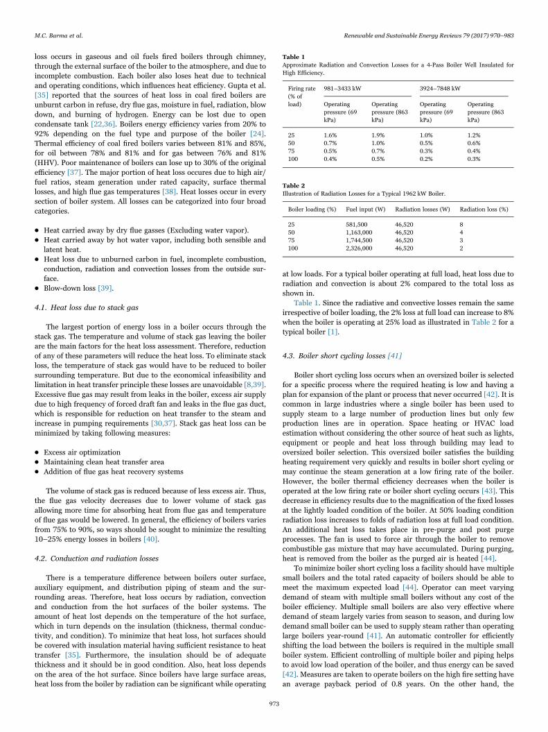
at low loads. For a typical boiler operating at full load, heat loss due toradiation and convection is about 2% compared to the total loss asshown in.
Table 1. Since the radiative and convective losses remain the sameirrespective of boiler loading, the 2% loss at full load can increase to 8%when the boiler is operating at 25% load as illustrated in Table 2 for atypical boiler [1].
4.3. Boiler short cycling losses [41]
Boiler short cycling loss occurs when an oversized boiler is selectedfor a specific process where the required heating is low and having aplan for expansion of the plant or process that never occurred [42]. It iscommon in large industries where a single boiler has been used tosupply steam to a large number of production lines but only fewproduction lines are in operation. Space heating or HVAC loadestimation without considering the other source of heat such as lights,equipment or people and heat loss through building may lead tooversized boiler selection. This oversized boiler satisfies the buildingheating requirement very quickly and results in boiler short cycling ormay continue the steam generation at a low firing rate of the boiler.However, the boiler thermal efficiency decreases when the boiler isoperated at the low firing rate or boiler short cycling occurs [43]. Thisdecrease in efficiency results due to the magnification of the fixed lossesat the lightly loaded condition of the boiler. At 50% loading conditionradiation loss increases to folds of radiation loss at full load condition.An additional heat loss takes place in pre-purge and post purgeprocesses. The fan is used to force air through the boiler to removecombustible gas mixture that may have accumulated. During purging,heat is removed from the boiler as the purged air is heated [44].
To minimize boiler short cycling loss a facility should have multiplesmall boilers and the total rated capacity of boilers should be able tomeet the maximum expected load [44]. Operator can meet varyingdemand of steam with multiple small boilers without any cost of theboiler efficiency. Multiple small boilers are also very effective wheredemand of steam largely varies from season to season, and during lowdemand small boiler can be used to supply steam rather than operatinglarge boilers year-round [41]. An automatic controller for efficientlyshifting the load between the boilers is required in the multiple smallboiler system. Efficient controlling of multiple boiler and piping helpsto avoid low load operation of the boiler, and thus energy can be saved[42]. Measures are taken to operate boilers on the high fire setting havean average payback period of 0.8 years. On the other hand, the
Table 1Approximate Radiation and Convection Losses for a 4-Pass Boiler Well Insulated forHigh Efficiency.
Firing rate(% ofload)
981–3433 kW 3924–7848 kW
Operatingpressure (69kPa)
Operatingpressure (863kPa)
Operatingpressure (69kPa)
Operatingpressure (863kPa)
25 1.6% 1.9% 1.0% 1.2%50 0.7% 1.0% 0.5% 0.6%75 0.5% 0.7% 0.3% 0.4%100 0.4% 0.5% 0.2% 0.3%
Table 2Illustration of Radiation Losses for a Typical 1962 kW Boiler.
Boiler loading (%) Fuel input (W) Radiation losses (W) Radiation loss (%)
25 581,500 46,520 850 1,163,000 46,520 475 1,744,500 46,520 3100 2,326,000 46,520 2
M.C. Barma et al. Renewable and Sustainable Energy Reviews 79 (2017) 970–983
973

installation of smaller boilers to increase the high-fire duty cycle has anaverage payback time of 1.9 years (U.S. DOE-IAC, 2006) [30].
4.4. Steam leaks
Steam leakage occurs from pipes, flanges, valves, connections,traps, and process equipment. It can be substantial for some steamdistribution systems. The amount of steam leaking from variousopenings depends on the size of the opening and the working pressure[1]. McKay et al. [45] have conducted a survey to locate and measurethe losses in a plant and concluded that the major part of the total losscould be attributed to a small number of large steam or condensateleaks. They also found that the malfunctioning of steam traps can pass25% live steam where the main boiler had an efficiency of 80%.
4.5. Fouling and scaling of boiler heat transfer surfaces
Fouling, scaling, and soot build up on heat transfer surfaces ofboilers act as insulators and lead to reduced heat transfer. This resultsin lower heat transfer to the water in the boiler and higher flue gastemperature. If at the same load conditions and same excess air settingthe flue gas temperature increases with time, this is a good indication ofincreased thermal resistance to heat transfer in the boiler. Typically, 1–1.5 mm soot build up on the fire-side can increase fuel consumption byabout 3–8%. Similarly, for the water-side, scale buildup of 1–1.5 mmcan result in additional fuel consumption of 4–9% [46]. In anotherstudy it is stated that 9.5% reduction in heat transfer can be found dueto the 0.03 in. (0.8 mm) of soot layer and in extreme case 69%reduction could result due to the soot layer thickness of 0.18 in.(4.5 mm) [47]. However, scale deposits occurs due to the presence ofcalcium, magnesium, and silica in most water supplies, which normallyreact to form a continuous layer of material on the waterside of theboiler heat exchange tubes. Researchers have shown that 0.04 in.(1 mm) of buildup can increase fuel consumption by 2% for water-tube boilers [47] and 5% for fire-tube boilers [48]. Moreover, scalingmay result in tube failures. Tests showed that for water-tube boilers0.04 in. (1 mm) of buildup can increase fuel consumption by 2%(CIPEC, 2001) [30,47]. When this occurs, the boiler heat transfersurface should be cleaned. On the fire-side, surfaces should be cleaned,while on the water side, scaling and fouling should be removed. Forboilers using gas and light oil, it is generally sufficient to clean fire-sidesurfaces once a year. However, for boilers using heavy oil, cleaning mayneed to be done several times a year. In addition, preventive stepsshould also be taken. For scaling, as it is caused by inadequate watertreatment, steps should be taken to improve water softening andmaintaining a lower total dissolved solids (TDS) level. For soot buildup, which is normally due to defective burner or insufficient air forcombustion, steps should be taken to repair or retune the combustionsystem [49,50].
4.6. Blowdown energy losses
Water evaporates in the steam drum leaving the solid particlespresent in the feed water in steam drum. These solid particles formsludge or sediments in the steam drum, which creates a thermalresistance between steam drum surface and water. Dissolved solids alsocause foaming and water carryover into the steam. Hence water neededto be drained at a certain time interval, from the bottom part of thesteam drum to retain the levels of suspended and total dissolved solids(TDS) within the standard limits. However, blowdown rate depends onthe boiler type, operating pressure, water treatment, and quality ofmakeup water, it could be in the range of 4–10% of boiler feed waterflow rate [30,31,51]. Blowdown losses account for about 1–3% of thefuel consumption [49], but this energy loss can be reduced, thus,makeup water and chemical treatment costs can be saved by optimizingblowdown rate [52]. An automatic blowdown-control system could be
used to maintain optimum blowdown rates with a simple paybackperiod of 1–3 year [30,48].
4.7. Heat loss due to moisture in the fuel
During combustion the moisture or liquid water present in the fueltakes sensible and latent heats tobecome super heated steam. Thesuperheated steam produced in the combustion chamber is at theadded cost of the heat of combustion going to chimney along with fluegas. The amount of heat taken by the moisture is directly proportionalto the amount of moisture present in the fuel. The amount of heat lossdue to moisture in fuel can be calculated using Eq. (1) [53,54].
M C T TGCV of fuel
Percentage of heat loss =× {2452.8 + × ( − )} × 100p f a
(1)
4.8. Heat loss due to incomplete combustion
Incomplete combustion of carbon could occur due to shortage ofoxygen in the combustion chamber. The product of incompletecombustion is carbon monoxide which results in the liberation of only52% of the total heat in the fuel. Thus product formed by incompletecombustion could be burned again with further release of energy. Theheat loss due to incomplete combustion can be expressed by Eq. (2)given below [53,54].
CO ppm mGCV of fuel
Percentage of heat loss =( ) × 10 × × 23746.8 × 28 × 100f
−6
(2)
4.9. Heat loss due to evaporation of water from combustion ofhydrogen in fuel
Hydrogen present in the fuel must be burned during combustion,and from water in the combustion product, which takes heat from thecombustion of fuel gets evaporated and finally come out to the chimneyas a superheated steam. Thus, heat is lost by sensible heating andevaporation of water. Percentage of heat loss by evaporation of waterdue to the presence of hydrogen in fuel can be calculated using the Eq.(3) below [53,54].
H C T TGCV of fuel
Percentage of heat loss =9 × × {245.8 + ( − )} × 100p f a2
(3)
4.10. Heat loss due to moisture present in air
Atmospheric air contains water vapor as a moisture. After combus-tion water vapor present in the combustion air becomes superheatedsteam at the cost of combustion heat. Thus, certain amount of heat islost due the presence of moisture in air. The percentage of this loss dueto moisture present in air can be calculated using Eq. (4) [53,54].
AAS Humidity C T TGCV of fuel
Percentage of heat loss =× × × ( − ) × 100p f a
(4)
4.11. Heat loss due to unburnt carbon in bottom and fly ash
The boiler ash studies shows variability in carbon contents that maybe a result of variations in retention time in the reactor, incompletecombustion, temperature variations and fluctuations and variations inmoisture content. Carbon content of ash is direct loss of useful carbonof fuel, which are expected to be burned in the combustion chamber[35]. Sensible heat loss ocurrs as the hot ash is being removed from thecombustion chamber. But due to some difficulties heat loss due tocarbon in ash and sensible heat in the fly ash could be ignored during
M.C. Barma et al. Renewable and Sustainable Energy Reviews 79 (2017) 970–983
974

heat loss analysis of the boiler [55].
5. Boiler energy savings measures
Regulagadda et al. [7] studied a coal fired steam turbine powerplant to find and locate exergy destruction processes. It was found that,maximum exergy destruction occurs in the boiler in a coal fired steamturbine power plant. Therefore, for improving the performance of thesteam turbine power plant, boiler performance should be improved,which results in largest improvement to the plant's efficiency [7]. Someenergy saving potentials for the steam distribution systems are shownin Table 3.
5.1. Excess air control
Combustion air is supplied to the combustion chamber of a boiler toburn the supplied fuel. Only oxygen of the supplied air takes part in thecombustion process and other parts of air takes sensible heat fromcombustion, which is going out along with combustion product throughchimney as a stack loss. Therefore, the amount of combustion airshould be as low as possible to minimize the stack loss. However, dueto some limitations only theoretical air cannot ensure completecombustion of fuels. To achieve complete combustion, supplied com-bustion air should be more than the theoretically required. Otherwise,higher percentage CO in flue gas or unburnt carbon in the ash could befound as result of incomplete combustion of fuel. Therefore, a boilershould be operated with optimum excess air to minimize the dry fluegas loss. For complete combustion, the optimum air flow can bemaintained by the employment of one of the following equipments:[1,24,56] (a) inlet damper control, (b) inlet vane control, (c) variablespeed control, and (d) measuring system for oxygen content of flue gas[57]. Chien-Li et al. had shown that when the excess air oxygenconcentration is reduced from 4% to 3%, the furnace efficiency is raisedby 0.6% [58].
Variable speed drive (VSD) is the most efficient control methodwhich provides the power to the fan motor that can overcome thesystem resistance at a given condition. Currently, it has been used inavailable modern industrial and commercial boilers. Application ofVSD is particularly effective in frequent low load conditions [59].Table 4 shows the prospective energy savings as a result of speedreductions due to the incorporation of VSDs in boiler fan.
VSD has been used in refrigeration, heating, ventilation and airconditioning of buildings to reduce energy uses [61]. Variable fre-quency drives (VFDs) are commonly used to vary pump and fan speedsin heating, ventilation and air conditioning of buildings as shown inFig. 5.
The higher turndown ratio reduces burner starts, saves wear andtear on the burner, provides better load control, reduces refractorywear, reduces purge-air requirements, and provides fuel savings [62].
5.1.1. Estimation of fuel savings associated with boiler fan speedreduction
Burner turndown ratio can be increased using a fan motor speedcontrol and hence fuel can be saved. Electrical energy could be saved
using an inverter to control the speed of an AC electric motor. Inaddition to this controlling the fan motor speed causes restricted excessair ratio and flue gas losses are minimized. Hence, application of VSDincreases the boiler efficiency and saves electrical energy. On the otherhand, reduced air supply saves fuel, cut emissions and prolongs the lifeof the boiler plant [12].
Stack gas loss (Lstack) can be expressed as:
L K T TCO
= ( − )stack
stack a
2 (5)
CO O CO= 1 −21
×22
2 max⎡⎣⎢
⎤⎦⎥ (6)
Value of (CO2) max is 15.9 and K is 0.53 for petroleum fuels could befound in Ozdemir [12]. Annual fuel saving is calculated using Eq. (7).
Fuel Savings (%) = New efficiency−Old efficiencyNew efficiency (7)
η L(%) = (100 − )stack (8)
Tables 5, 6 present the input data needed for boiler flue gas energyanalysis.
5.2. Digital control of excess air
The oxygen trim control system will maintain the optimum air fuelratio, so that the highest possible combustion efficiency could beachieved [39]. The efficiency of the boiler with oxygen concentrationin flue gas has been shown in Fig. 6. A digital monitoring controlsystem can be used to achieve best excess air control. This systemmeasures the oxygen and carbon dioxide percentage in exhaust-gas bya probe. According to the measured data, a central digital controllerwill vary the combustion air flow by controlling inlet damper [63,64].
Based on the measured oxygen percentage in the flue gas, the inlet
Table 3Energy Efficiency Measures in Industrial Steam Distribution System [37].
Measure Fuel Saved Payback Period (Yrs) Implementation Potential Other Benefits
Improved insulation 3–13% 1.1 100%Improved steam traps Unknown Unknown – Greater reliabilitySteam trap maintenance 10–15% 0.5 50%Automatic trap monitoring 5% 1 50%Leak repair 3–5% 0.4 12% Reduce requirement for major repairsFlash steam recovery/ Condensate return 83% Unknown – Reduce water treatment costCondensate return alone 10% 1.1 2% Reduce water treatment cost
Table 4Potential savings from VSD [60].
Average speed reduction (%) Potential energy savings (%)
10 2220 4420 6140 7350 8360 89
Fig. 5. The block diagram of the variable speed drive system [1,12].
M.C. Barma et al. Renewable and Sustainable Energy Reviews 79 (2017) 970–983
975

air damper will be automatically adjusted to attain an optimum excessair set point. To achieve maximum possible combustion efficiency, therequired excess air is different for different fuel, as the combustionprocess of different fuel is not same. Thus for optimizing the combus-tion efficiency of gas fired boiler, the oxygen concentration set pointshould be 1.7%, which corresponds to 10% excess air that provideshighest combustion efficiency [65,66]. Fig. 7 displays the boiler oxygentrim system fitted on boiler.
To achieve maximum combustion efficiency during boiler opera-tion, percentage of supplied excess air should be 5–10% for natural gas,5–20% for fuel oil, 15–60% for coal [68]. The variation of combustionefficiency and Stack temperature with different amount of excess air ispresented in Table 7 [68,69].
5.3. Improving combustion efficiency
Combustion efficiency is directly related to the liberation of energycontent of a fuel through combustion reaction and transfer into usableheat. It can be measured by measuring the exhaust temperature,oxygen or carbon monoxide concentrations in flue gas. Thus, lowercombustion efficiency also leads to high emissions of unburnt pollu-tants such as CO and soot [70]. In ideal case, a precise amount of air isrequired to completely react with given quantity of fuel. In realcombustion, the proper mixing of air and fuel cannot be achievedand “excess” air must be supplied to completely burn the fuel. Loweramounts of supplied air will generate incomplete combustion (carbonmonoxide emission) or unburnt carbon in bottom or fly ash. Thus, aportion of heat content of the fuel is being wasted. Due to furtherreaction of carbon monoxide and unburnt carbon can generate acertain amount of heat. On the other hand, too much excess airincreases the stack loss by increasing the flue gas volume andconsequently the oxygen concentration in flue gas will increase.Therefore, the amount of excess air should be optimized by analyzingflue gas oxygen or carbon monoxide concentrations [41].
Stoichiometric air is the minimum amount of air that contains
required amount of oxygen for complete combustion of a given fuel.The example of the chemical equation for the combustion of natural gaswith stoichiometric air is
CH O N CO H O N+ 2( + 3.76 ) → + 2 + 7.524 2 2 2 2 2 (9)
From the above example, it is clear that stoichiometric air fordifferent fuel should be different as the chemical formula and con-stituent chemical elements are not similar. The mass of air required tocompletely combust one unit mass of a given fuel is known asstoichiometric air fuel ratio. For natural gas, AFs is about 17.2 kg-air/kg-ng. The quantity of air supplied in excess of stoichiometric air iscalled excess air, EA. The combustion temperature, Tc, can becalculated from an energy balance on the combustion chamber (Fig. 8), where the chemical energy released during combustion isconverted into sensible energy gain of the gasses [67,71,72].
The energy balance equation can be written in terms of inlet airtemperature (Ta), LHV, stoichiometric air fuel ratio, excess air (EA),and combustion gas specific heat (Cpg) [67].
T T LHV EA AF C= + /[{1 + (1 + ) × } ]c a s pg (10)
Combustion efficiency can be primarily identified by measuring theamount of unburned carbon in bottom and fly ash and oxygen in theexhaust. Gaseous and liquid fuels can be burnt using well-designedconventional burners at excess air levels of 15%, but in order to reduceemissions high excess air level of 25% is required. Li et al. had shownthat retrofitting a coal fired boiler with louver concentrators andmodified seconday air reduces the carbon content in the fly ash greatlyfrom 9.55% to 2.43% [73]. Combustion efficiency is not the same for allfuels. In general, gaseous and liquid fuels burn more efficiently thansolid fuels [74].
5.4. Heat recovery from flue gas
Boiler exhaust temperature ranges from 150 to 250 °C [75] due tothe limitation in heat transfer area between combustion product andwater or steam and condensation of flue gas. Thus, a huge amount ofheat energy is lost through boiler exhaust or flue gasses. About 10–20%of input energy may be lost through high temperature flue gas [6].Therefore, boiler efficiency could be improved by recovering part of thetotal heat content of flue gas. This heat can be used to preheatcombustion air, boiler feed water within the boiler, or as driving heatsource for other purposes such as absorption chiller.
5.4.1. EconomizerThe common way of recovering heat from the flue gas is preheating
of feed water and combustion air using a heat exchanger (commonlycalled an economizer) installed as shown in Fig. 9. The amount of heat
Table 5Concentration of O2 and stack gas temperature with and without VSD [12].
With variable speeddrive
Without variable speeddrive
Concentration of O2 (%) 6.9 13.9Stack gas temperature (°C) 146 195Ambient temperature (°C) 36 36
Table 6Input data for boiler energy analysis [12].
CO2 (%) K Dry flue gas
With variable speed drive 10.6 0.53 5.5Without variable speed drive 5.38 0.53 16.2
Fig. 6. Combustion efficiency versus oxygen concentration [1].
Fig. 7. Oxygen trim system for flue gas recovery [67].
M.C. Barma et al. Renewable and Sustainable Energy Reviews 79 (2017) 970–983
976

recovered depends on the temperatures of flue gas and fluid to beheated. But the major problem associated with flue gas heat recovery iscorrosion due to acid condensation [9,76]. The sulfur in the fuelcombines with oxygen during combustion to form sulfur dioxide, whichcombines with steam resulting sulfuric acid in the flue gas. Steam isformed by the oxidation of hydrogen and moisture present in the fuel.Thus, acid condensation takes place when the flue gas is cooled belowits acid dew point [77].
Therefore, to prevent acid condensation the flue gas temperaturecould be minimized to a certain temperature which is well above theacid dew point temperature. Otherwise, heat recovery system should bedesigned to withstand acid corrosion. The amount of acid content influe gas is directly related to sulfur content of the fuel. Therefore,allowable minimum exhaust temperature also depends on the fuel usedin boiler. Some allowable exit stack temperature are given in Table 8[1].
5.5. Preheating combustion air
Combustion air preheating is the most potent way to enhance theboiler efficiency and steam generation [78–80]. High temperatureexhaust gas stream can be used as the source of the heat energy and
a heat exchanger can be used to transfer the heat energy to theincoming combustion air [81,82]. Thus combustion air gains a largeportion of sensible heat that is required to take part in the combustionprocess. Fuel savings for different flue gas temperature and resultedpreheated combustion air temperatures are shown in the Table 9 below[83].
5.6. Condensate recovery
In most steam systems, steam is used for process heating byextracting its latent heat. The resulting condensate is at steamtemperature and still contains a considerable amount of energy. Forexample, if steam is used at 690 kPa, then the condensate containsabout 25% of the heat used to produce steam and will be lost if thecondensate is not returned to the system [84–88]. Therefore, returningcondensate to the boiler feed water tank will result in significant fuelenergy savings. Since, condensate is the distilled water which is idealfor use as boiler feed water. Therefore, condensate recovery helps toreduce water consumption (water cost), water treatment cost, and blowdown [1,89]. A piping network is needed to be employed for recoveringcondensate from different heating facilities, which involves a financialinvestment. But, the substantial savings in energy and chemicals costsmakes building a return piping system attractive. It has been found that2% of the boiler population can achieve a 10% energy savings with apayback period of 1.1 years [9,90,91].
5.7. Steam traps
Steam traps are used in steam systems to remove condensate andnon-condensable gases. They are mainly used in buildings for steamheating coils and for condensate removal from steam headers, asshown in Fig. 10. There are many types of steam traps as shown inFig. 11. The operation of steam traps is important because if they fail tooperate properly and allow live steam to pass through them from thesteam side to the condensate side, it results in obvious loss of energy[92]. In addition, if the traps are unable to remove air at start-up timesor if they are unable to remove condensate at a sufficient rate, theresulting reduced capacity and longer periods to heat up would alsoresult in energy wastage. Water hammering can eventually result indamage to valves and other components in steam systems, which couldresult in steam leaks [1,93,94]. By ensuring the proper operation ofsteam traps, significant amounts of energy can be saved. Steam trapsare needed to be monitored regularly, which can prevent the mal-functioning of 15–20% of the traps. A regular system of steam trap withregular checking program and follow-up maintenance is also able tosave energy up to 10% [91,95,96] and the payback period is 0.5 years[90]. Though the payback period is very short, this is not implementedin every steam system because some steam plant management sepa-rately budget their maintenance and energy costs. Addition of auto-mated monitors and maintenance program can save even more energy,without significant extra cost. This system will improve the mainte-nance program, because automated monitoring can give quickerresponse if a steam trap fail or malfunction. Using automatic monitor-ing is estimated to save an additional 5% over steam trap maintenance,with a payback of 1 year [95,97].
Table 7Combustion efficiency at different excess air [68].
Combustion Efficiency (%)
Excess % Net Stack Temperature (oC)
Air Oxygen 93 149 204 260 316
9.5 2.0 85.4 83.1 80.8 78.4 76.015 3.0 85.2 82.8 80.4 77.9 75.428.1 5.0 84.7 82.1 79.5 76.7 74.044.9 7.0 84.1 81.2 78.2 75.2 72.181.6 10.0 82.8 79.3 75.6 71.9 68.2
Fig. 8. Energy balance for combustion chamber.
Fig. 9. Arrangement of a typical economizer.
Table 8Acid Dew point for Common Fuel Types [1].
Fuel Acid dew point temperature(oC)
Allowable exit stacktemperature (oC)
Natural gas 66 120Light oil 82 135Low sulfur oil 93 150High sulfur oil 110 160
M.C. Barma et al. Renewable and Sustainable Energy Reviews 79 (2017) 970–983
977

5.8. Heat recovery technology
From economical point of view the equipment which needs mini-mum capital outlay are preferable for recovering waste heat and totransfer to a suitable heat sink. Harnessing the waste sources withinthe system is also preferable from which it is being emitted [98].Preheating combustion air and boiler feed water are the first choice toutilize the recovered heat from boiler exhaust. Some other solutionrequires higher investment such as heat pumps to provide a tempera-ture lift [99,100], Organic Rankin Cycle or Kalina Cycle to generateelectricity [101–103], absorption refrigeration cycle for providing airconditioning or cooling effect [104–106]. Heating requirement outsidethe boundaries of the boiler plant is also an option for a third party toharness the waste heat source but these options also require highercapital investment and long payback period [107]. However, initialtechnology selection criteria are based on the temperature and flowrate of boiler exhaust. Required temperature and flow rate of exhaustvaries for the equipments which are expected to run by the exhaust.Some parameter of boiler exhaust (dust, sticky) also influences thetechnology selection process. Efficiency of heat recovery and ease ofinstallation, project payback period also have the significant influenceon technology selection [107–109].
5.8.1. Heat exchanger technologyThere are two types of heat exchangers, Gas-gas heat exchanger and
Gas-liquid heat exchanger that can be used to recover waste heat fromboiler exhaust [107,110–112]. The most common use of Gas-gas heatexchanger is preheating combustion air by passing the boiler exhaustand fresh air in different flow configuration between plates or tubesthrough which heat is transferred [113]. This heat exchanger also canbe used for heating any gaseous substance or fresh air to fulfill aprocess requirement. Rotating regenerators or heat wheels and plateheat exchanger are the generally used gas-gas heat exchanger [114].Gas-liquid heat exchanger is also commonly used heat exchanger in thesteam generation system. Generally, it is used for heating boiler feedwater using boiler exhaust. It is known as economizer which widelyexists in both industrial and domestic applications [115–117].
5.8.2. Heat pump systemsHeat pumps are able to create a temperature lift of a heat source
which makes the heat source useable at higher temperature and in caseof waste heat recovery from low temperature exhaust; this technologycan lift the temperature for using the recovered heat at highertemperature [118]. It is potential to create temperature lift of boilerexhaust economically in excess of 40 °C, but the overall efficiency isreduced due to energy requirement of the heat pump [107]. Applicationof heat pump is common all over Europe but fewer in UK. A surveyregarding public attitude on waste heat recovery [119,120] revealed amajor portion of the food industry in UK considers heat pumps as a‘risky’ or ‘unsure’ even though the payback period varies from 2 to 5years [99,100,121] in some case studies in UK. UK government hasbeen emphasizing on heat pump application through latest schemes toencourage the utilization of this technology [107,122].
5.8.3. Electricity generation
5.8.3.1. Thermoelectric units. Thermoelectric module works on thetemperature differential and produces electric current at the electricterminals [123–125]. The module is a collection of p-n couples whichare thermally in parallel and electrically in series. According to theprovided data by manufacturer Hi-Z [126,127], a thermoelectricmodule can generate electric power in the range of 20–50 W for atemperature difference of around 200 °C. Thus large number ofmodules in series can be configured to increase the amount ofgenerated power [128,129]. Since the energy conversion efficiencyand electrical output of the modules is extremely low, if there is arequirement for a low electrical power near the heat source,thermoelectric modules could be used by utilizing waste heat source.Thermoelectric modules may not be the most desirable due to lowenergy conversion efficiency, but as a potential option it could beinvestigated for individual cases [107,130].
5.8.3.2. Rankine cycle. A heat source is needed to vaporize a workingfluid which in turn would drive a turbine. The turbine is connected tothe electric generator which will generate electricity. The working fluidwould then be condensed and returned to the heat source. As thetraditional Rankine cycle is not suitable for heat sources below around240 °C, the organic Rankine cycle (ORC) with organic working fluidscould be used for electricity generation by recovering waste heat fromboiler exhaust. It has been reported that organic Rankine cycle could besuitable for electricity generation using sources as low as 40 °C [131].DRD Power [132] have been demonstrated a 200 kW unit using lowpressure steam, which is installed in a chemical factory with jointfunding of Carbon Trust and a number of sources [133]. But OrganicRankine cycle offer efficiency (up to 18% [103]) and the capital costsare high. It could be preferable if government aid on funding isavailable for such a project, thus the payback period could be
Table 9Percent Fuel Savings Gained from Using Preheated Combustion Air [83].
Furnace ExhaustTemperature, °C
Preheated Air Temperature °C/ Percent of fuel savings
316 427 538 649 760 871
538 13 18 – – – –
649 14 19 23 – – –
760 15 20 24 28 – –
871 17 22 26 30 34 –
982 18 24 28 33 37 401093 20 26 31 35 39 431204 23 29 34 39 43 471316 26 32 38 43 47 51
Fig. 10. Application of steam traps [1].
Fig. 11. Common types of steam traps [1].
M.C. Barma et al. Renewable and Sustainable Energy Reviews 79 (2017) 970–983
978

considerably decreased [134,135].
5.8.3.3. Kalina cycle. An updated and customized version of OrganicRankine cycle known as Kalina cycle, which can be used for exploitingthe waste heat sources. Ammonia-water mixture is the working fluid ofthe Kalina cycle and as the boiling of mixture occurs over a wide rangeof temperatures which enables the Kalian cycle to recover heat from theboiler exhaust until the exhaust temperature is reached to a lower limit[51]. This system needs to use a lower pressure heat exchanger andallows varying the concentration of ammonia in water at the condenseraccording to the temperature of heat source [51]. Researchers haveshown that the Kalina cycle with novel features is capable to increasethe output power of up to 20% compared to ORC [136]. However, astudy found that this improvement may be as small as 3% [137], whichmay not be enough to cover the higher maintenance costs and higherinvestment [138,139]. Currently, it can be found in low-grade wasteheat recovery and geothermal power plants [140]. This cycle is apotential choice to recover waste heat from boiler exhaust and generateelectricity. But it still needs further demonstration to confirm theprojects justifiability.
5.8.3.4. Micro co-generation. In order to comply with the Kyotocommitment, Japan was required to reduce its greenhouse gas(GHG) emissions by 14% on average during the period between 2008and 2012 [141,142]. Furthermore, in order to realize a sustainable low-carbon society, Japan has announced drastic goals to curb theemissions of GHG, with 2050 as the target year, as well as scenariosfor achieving the goal. However, Japan had increased total GHGemissions by 12.2% in 2007, among which, the residential sectoradded the GHG emission by 10.8% [143]. Cogeneration has beenconsidered worldwide as the major alternative to traditional systems interms of significant energy saving and environmental conservation aswell as GHG emission [144,145]. Heat should be produced incombination with power, as this increases energy efficiencysignificantly which is an extremely important to energy sustainability[146]. The most promising target in the application of CHP lies inenergy production for buildings, where small-scale and microscale CHPis usually installed [147]. Small-scale and micro-scale CHP systems canhelp to meet a number of energy and social policy aims, including thereduction in greenhouse gas emissions, improved energy security,investment saving resulted from the omission of the electricitytransmission and distribution network, and the potentially reducedenergy cost to consumers [148]. Currently, micro-scale and small-scaleCHP systems are undergoing rapid development, and are emerging onthe market with promising prospects for the near future [147,148].Combination of cogeneration technologies to various thermally fedsystems such as absorption or engine-driven chillers [149–153] allowfor setting up a so-called trigeneration system. In addition, high-efficiency electro-energetic technologies such as electric heat pumps[150,152] well fit into the existing energy systems to enhance theoverall performance. Bernotat and Sandberg [146,154] reported on thepossibilities of using CHP for clustered dwellings in Sweden and theBaltic states, concluding that small scale CHP has high perspectives ifthe total heat demand in an area is high enough. Dentice d’Accaciaet al. [145] reported on the possibilities of residential micro-CHPsystems. They present a general survey of market and technologicalperspective. A demonstration project was reported with a fuel cell inRef. [155]. The experiments were aimed at assessing the suitability ofthis kind of system to supply Italian residential customers. Voorspoolsand D’haeseleer [156] analysed the response of a gas enginecogeneration unit in a house to a certain heat demand. It was shownthat an engine is rather slow in response for heating, whereas theelectric transient is negligible.
5.8.4. Absorption refrigeration systemsTo run absorption refrigeration cycle a heat source is needed
instead of a compressor. The working fluid is vaporized upon heatingat generator by a low temperature waste heat source (boiler exhaust)and then condensed at the condenser. This condensed fluid flowsthrough an expansion valve to the evaporator, where it is expected togain latent heat and make the refrigeration effect [106]. Commerciallyavailable systems are mainly based on lithium bromide/water andammonia/water solution. These systems can achieve cooling tempera-ture as low as 7 °C using a waste heat source such as low temperatureexhaust [104]. To install an 800 kW sized unit, the overall investmentis expected to be around £150,000 (excluding pumps and pipework[104]). Commercial exhaust driven absorption chiller with variouscapacity can be found in [105,157]. This type of refrigeration systemsmay preferable in plants requiring which have low grade waste heatsource and also need a lot of refrigeration effect within their plant[158]. However, payback periods for introducing absorption refrigera-tion system in an existing boiler could be around 10 years but, for anew build plant it becomes around 3 years [104].
6. Role of maintenance on boiler energy savings
Systematic boiler maintenance can evade unanticipated failure andminimizes unexpected boiler downtime and energy consumption [159].Maintenance task should be performed for daily, weekly, monthly andannually basis. A written record should be kept for all performedmaintenance work [160]. To ensure the scheduled maintenance work,checklists could be used which will records of executed works and are away to communicate the boilers’ status [161]. All checklists and otherrecord documents should be systematically filed for reference [45,162].
6.1. Keep the boiler clean
Fouling on fire and water side of the boiler tubes is a very commonproblem of the steam generation system. In fire side of the tubesaccumulation of deposits occurs from burning fuel, and the growth ofthe deposits depends on the types of fuel. Solid fuels tend to foul muchmore than liquid and gaseous-fueled boilers [47,48,69,163]. Similarly,heavy oil fired boilers face greater fouling problems whereas naturalgas fired boilers face a comparatively very low fouling [164,165]. Themost likely causes of fouling are low air-to fuel ratios, improper fuelpreparation or malfunctioning burner. Dissolved minerals in waterforms deposits or scale on waterside of the boiler tubes. Watersidedeposit/scale inhibits the heat transfer from tube wall to water which inturn raises the tube wall and flue gas temperatures. An automaticsensor could be used to measure the scale buildup in the running boilerand can be treated chemically [166]. Boiler feed water should be testeddaily in small low-pressure boilers and hourly in large high pressureboilers [167]. Large boilers are often equipped with soot blowers tofacilitate cleaning the fireside tube surfaces. Regular inspection andcleaning is suggested for small boilers [4168].
6.2. Improve boiler insulation
A simple and economical way of reducing heat loss throughradiation and convection is by adding insulation directly to the outerwalls of the boiler as well as steam pipes. New materials such asceramics, fibers which are having a lower heat capacity should be usedfor insulation. According to the rule of thumb, any surface above 50 °Cshould be insulated, including steam and condensate piping, boilersurfaces, valves and fittings. Damaged or worn out insulations shouldbe changed and hot spots on boiler casing should be checked and fixed.Outer skin temperature should not be more than 50 °C [169].
M.C. Barma et al. Renewable and Sustainable Energy Reviews 79 (2017) 970–983
979

Researchers have shown that the improved insulation can save 6–26%[170,171]. Moreover, removed insulation during repairing on steamsystems should be reinstalled. Brittle and rotten insulation should befound out by doing regular inspection and replacing with new insula-tion material can save energy [171].
6.3. Minimize wasted blowdown water
Blown down is the periodical hot water discharge from the bottomof the steam drum to prevent scale formation on boiler tubes. Energygained by the hot water is being wasted due to this blowdown processand more frequent blowdown intensify this energy loss. Automaticblowdown controls can be used to maintain premeditated boiler waterconductivity, TDS, silica, chlorides, alkalinity and acidity to minimizeenergy through blowdown water [51,172]. For further energy savings,boiler feed water can be preheated by recovering waste heat fromblowdown water and approximately 1% improvement on system'sefficiency could be achieved [5,173,174].
6.4. Maintenance activities
To confirm cleaned boilers for allowing maximum heat transfer andproper functioning of the safety devices, water supply system, fuelsupply systems, electrical components and systems, etc. a scheduledmaintenance is necessary [175]. Some other activities are also neededto be done to ensure the boiler operation at high efficiency such asperiodical combustion test using flue-gas analysis [22]. Boiler main-tenance works can be listed as follows.
• Proper functioning of shut off valves without any water leakage isneeded to be ensured.
• Broken pieces or cracks in the refractory walls or layers should berepaired.
• Proper functioning of controls, safety devices, and indicators,including the low-water cutoff devices and regulators, pressuregauge, safety valves, and the pressure release valve should beensured in the maintenance period.
• Fuel feed system and burners, particularly if your boilers use liquidfuels should be checked carefully. Not doing so will result ininefficient combustion and heat transfer, resulting in higher fuelcosts and less effective heating.
• Be sure to clean boiler heat transfer surfaces regularly to removebuildup of soot. Soot can act as an insulator which cuts down on theefficiency of the heat transfer between combustion gas and steamgeneration [176].
7. Information, education and awareness
Education as a body of knowledge shows indispensable andnecessary tools to create awareness and change attitude and values ofindividuals. Through education people became aware of the citizenshipproblems, the rational use of energy, and consequently mitigating thepresence of barriers, mainly the behavioral ones [177–179]. Peoplethink about energy as a commodity and became aware of the fuel price,a social necessity or an ecological resource [179–181]. Table 10 showsenergy savings in Brazil using educational program.
Publications and seminars are the main tools for disseminatingenergy related information. Publications should be targeted audienceoriented and technically sound. Hence, several types of publicationswith appropriate information should be available for different groups ofpeople from maintenance staff to accountants. Another successful wayof spreading information is through seminars. They should avoid beingtoo general on one hand and too academic on the other. In order topresent interesting case stories in publications and seminars, it is agood approach to set up pilot projects that deal with specific problems.An energy guide label with details of energy savings feature in many
countries found to be effective to raise the awareness among the users.Mass media can play an important role by disseminating useful energysavings information to the users so that users may follow energyefficient rules while they use equipment/machineries [33,182–184]. Awell-planned employee energy awareness campaign provides a plat-form to engage and educate [22,185] the workforce by.
• Building a greater understanding of the importance of energyefficiency.
• Creating a sense of ownership for energy management plan.
• Focusing attention on the key issues of importance to an organiza-tion.
• Demonstrating how individuals can help to achieve organizationalgoals.
8. Conclusions
Boilers are commonly used as steam generation systems in differentindustries for the heating processes. Thermal power plants use boilersto generate steam for steam turbines. A significant portion of the worldenergy consumption is found to be used for operating boilers aroundthe world to facilitate the heating process or power generation.However, the typical boiler efficiency is in the range of 75–90% andthe remaining part of the energy is lost as different forms of wastedheat. To evaluate the efficiency of the boiler and the amount of heatthat is wasted from the boiler, energy audit can be performed. Thishelps to quantify the amount of heat lost through different sources andidentify the potential source of waste heat. The efficiency of the boilercan be improved by taking measures to control the potential of wasteheat sources.
Heat loss from the boiler occurs in several ways, and stack gas lossis the major source of heat loss among other sources of heat loss. Dueto the limitation of acid dew point of stack gas this loss cannot beeliminated, but could be minimized by recoverying waste heat from theboiler exhaust and utilizing the recovered waste heat within the boilersystem. Other sources of heat loss such as boiler short cycling andblowdown occurs due to removing of hot water from the steam drum torun the boiler efficiently. However, excessive short cycling and blow-down causes higher heat loss as the hot water is being drained from thesteam drum. Some losses occur due to fuel and combustion air quality,such as moisture in fuel and moisture in air. This moisture consumesheat to evaporate and mix with the exhaust gas. Heat loss due to theconduction and radiation occures from the uninsulated surface of theboiler, fouling, and scaling which hinders heat transfer from hightemperature combustion product to the water, due to incompletecombustion, energy content of the fuel could not be liberated.Causes, effects, and proposed remedies for the sources of heat lossare reviewed from literature in this study.
Energy saving measures for boiler have also been reviewed anddiscussed in detail in this study. Different types of energy savingtechniques such as excess air control, improving combustion efficiency,utilization of waste heat content of flue gas, and condensate recovery,etc., have been reviewed. An optimized excess air could be maintainedusing variable speed driven ID fan. VSD operated ID fan consumes lessamount of electrical power as well as optimized excess air will reducestack gas loss by reducing the amount of stack gas. Combustion
Table 10Energy savings with educational program [177].
Energy saved Avoided demand-peak
Investments Cost (US$/kWh)
GWh/yr) % MW/yr % US$x103 %
69.71 9.2 7.55 3 744.86 0.7 0.010
M.C. Barma et al. Renewable and Sustainable Energy Reviews 79 (2017) 970–983
980

efficiency can be improved using well designed nozzle or combustionprocess with minimum use of excess air. By using proper functioning ofsteam trap and recovering condensate, a significant amount of energycan be saved. Finally, heat recovery technologies can be used to recoverwaste heat from boiler exhaust and exploit that recovered heat togenerate electricity or refrigeration effect. Recovered heat also can beused to preheat combustion air or feed water within the system. Propermaintenance of boiler also helps to save energy and to run the boiler atits maximum efficiency. In order to maximize the heat transfer fromflue gas to water and minimize the heat loss in other parts of the boiler,cleaning of heat transfer surfaces on both water and fire side must beconducted. Proper functioning of other equipments need to be con-firmed during maintenance work. Moreover, attitude and values ofindividuals towards energy use needed to be improved throughcontinuous dissemination of knowledge by education, awairness,seminars, or conferences among the technical staff.
9. Recommendations for future work
This study focused on the energy consumption by the boiler forgenerating steam in different purposes, causes of heat loss and energysaving opportunities in the steam generation system. To estimate theamount of heat lost from a boiler or the operating efficiency of theboiler, energy audit could be done. Hence, the procedure to carryout anenergy audit in the steam generation plant has been included in thisstudy. However, most of the boilers have been operated without havingperiodical energy audit. Though the energy loss through different partsof a new boiler is within the tolerable limit, but energy loss is supposedto be increased with increasing oprating period of the boiler. Thus,energy flow of the boiler needs to be audited at specific time intervals,which helps to identify the sources of major energy loss. The majorenergy loss occurs due to different causes and can be minimized bytaking different remedial actions or using techonologies. Retrofitting ofthese technologies is needed to be examined experimentally andfurther technological improvement of them may encourage the enduser. Moreover, boiler operation staff as well as other non-technicalstaff needs to be properly educated and aware about fuel price andimpact of fuel consumption.
References
[1] Jayamaha L. Energy-efficient building systems: green strategies for operation andmaintenance. McGraw Hill Professional; 2006.
[2] (EIA), Enternational energy annual. online, retrieved [cited 2009 3rd January2009]; 2007.
[3] Statistics UEH. Breakdown of Electricity Generation by Energy Source [cited 201521.09.2015]; Available from: ⟨http://www.tsp-data-portal.org/Breakdown-of-Electricity-Generation-by-Energy-Source#tspQvChart⟩; 2015.
[4] Som S, Datta A. Thermodynamic irreversibilities and exergy balance in combus-tion processes. Progress Energy Combust Sci 2008;34(3):351–76.
[5] Ganapathy V. Industrial boilers and heat recovery steam generators: design,applications, and calculations. CRC Press; 2002.
[6] Saidur R, Ahamed JU, Masjuki HH. Energy, exergy and economic analysis ofindustrial boilers. Energy Policy 2010;38(5):2188–97.
[7] Regulagadda P, Dincer I, Naterer GF. Exergy analysis of a thermal power plantwith measured boiler and turbine losses. Appl Therm Eng 2010;30(8–9):970–6.
[8] ERC I. How to Save energy and money in boilers and furnace systems. Energy ResCent (ERC) 2004.
[9] Einstein D, Worrell E, Khrushch M. Steam systems in industry: energy use andenergy efficiency improvement potentials. Lawrence Berkeley NationalLaboratory; 2001.
[10] Basu P, Kefa C, Jestin L. Boilers and burners: design and theory. Springer Science& Business Media; 2012.
[11] Kouprianov V, Chullabodhi C, Kaewboonsong W. Cost based optimization ofexcess air for fuel oil/gas-fired steam boilers. Int Energy J 2007;21(2).
[12] Ozdemir E. Energy conservation opportunities with a variable speed controller in aboiler house. Appl Therm Eng 2004;24(7):981–93.
[13] Beggs C. Energy: management, supply and conservation. Routledge; 2010.[14] Yeh S, Rubin ES. A centurial history of technological change and learning curves
for pulverized coal-fired utility boilers. Energy 2007;32(10):1996–2005.[15] Mecrow B, Jack A. Efficiency trends in electric machines and drives. Energy Policy
2008;36(12):4336–41.[16] Bayindir R, Sagiroglu S, Colak I. An intelligent power factor corrector for power
system using artificial neural networks. Electr Power Syst Res 2009;79(1):152–60.[17] Colak I, Bayindir R, Sefa I. Experimental study on reactive power compensation
using a fuzzy logic controlled synchronous motor. Energy Convers Manag2004;45(15):2371–91.
[18] Bonaros V. et al. Analysis of the energy and cost savings caused by usingcondensing boilers for heating dwellings in Greece. In: Proceedings of the 5thInternational Conference on Applied Energy ICAE2013, Pretoria, Paper; 2013.
[19] Jorgenson DW, Wilcoxen PJ, Reducing . US carbon emissions: an econometricgeneral equilibrium assessment. Resour Energy Econ 1993;15(1):7–25.
[20] Jorgenson DW, Wilcoxen PJ, Reducing . US carbon dioxide emissions: anassessment of different instruments. J Policy Model 1993;15(5):491–520.
[21] Glaeser EL, Kahn ME. The greenness of cities: carbon dioxide emissions andurban development. J Urban Econ 2010;67(3):404–18.
[22] Bujak J. Minimizing energy losses in steam systems for potato starch production. JClean Prod 2009;17(16):1453–64.
[23] Hoffert MI, et al. Advanced technology paths to global climate stability: energy fora greenhouse planet. science 2002;298(5595):981–7.
[24] Regulagadda P, Dincer I, Naterer G. Exergy analysis of a thermal power plant withmeasured boiler and turbine losses. Appl Therm Eng 2010;30(8):970–6.
[25] Saidur R, Mekhilef S. Energy use, energy savings and emission analysis in theMalaysian rubber producing industries. Appl Energy 2010;87(8):2746–58.
[26] Agency USEI. Form EIA-923 Detailed Data [cited 2016 25.1.2016]; Availablefrom: ⟨http://www.eia.gov/electricity/data/eia923/⟩; 2015.
[27] Gingerich DB, Mauter MS. Quantity, quality, and availability of waste heat fromUnited States thermal power generation. Environ Sci Technol2015;49(14):8297–306.
[28] Moran MJ, et al. Fundamentals of engineering thermodynamics. John Wiley &Sons; 2010.
[29] Black V, et al. Power plant engineering. New York: International Thomson; 1996.[30] Hasanbeigi A. Energy-efficiency improvement opportunities for the textile
Industry. Lawrence Berkeley National Laboratory; 2010.[31] Bhatt MS. Energy audit case studies I—steam systems. Appl Therm Eng
2000;20(3):285–96.[32] Fromme JW. Energy conservation in the Russian manufacturing industry.
Potentials and obstacles. Energy Policy 1996;24(3):245–52.[33] Saidur R. A review on electrical motors energy use and energy savings. Renew
Sustain Energy Rev 2010;14(3):877–98.[34] Bujak J. Mathematical modelling of a steam boiler room to research thermal
efficiency. Energy 2008;33(12):1779–87.[35] Gupta RD, Ghai S, Jain A. Energy Efficiency Improvement Strategies for Industrial
Boilers: a Case Study. J Eng Technol 2011;1(1):52.[36] Bujak J. Energy savings and heat efficiency in the paper industry: a case study of a
corrugated board machine. Energy 2008;33(11):1597–608.[37] Einstein DW, Ernst Khrushch. Marta, Steam systems in industry: energy use and
energy efficiency improvement potentials. Lawrence Berkeley NationalLaboratory; 2001.
[38] Kaya D, Eyidogan M. Energy conservation opportunities in an industrial boilersystem. J Energy Eng 2010;136(1):18–25.
[39] Kilicaslan I, Ozdemir E. Energy economy with a variable speed drive in an oxygentrim controlled boiler house. J Energy Resour Technol 2005;127(1):59–65.
[40] Showers G. Boiler operation efficiency: insights and tips. Heat/Pip/air Cond Eng2002;74(11):53–6.
[41] ⟨www.oit.doe.gov⟩. 2009 20/11/2009].[42] ⟨http://oee.nrcan.gc.ca/industrial/equipment/boilers/operation.cfm?Attr=24⟩.[43] Losses C, Minimize Boiler Short Cycling Losses.[44] Losses MBSC, Energy Tips–Steam.[45] McKay G, Holland CR. Energy savings from steam losses on an oil refinery. Eng
Costs Prod Econ 1981;5(3–4):193–203.[46] Ltd LEP. BEST PRACTICE GUIDE FOR IMPROVING ENERGY EFFICIENCY OF
FOOD MANUFACTURING PLANTS IN SINGAPORE. 2016 [cited; Availablefrom: ⟨http://www.e2singapore.gov.sg/DATA/0/docs/Resources/Industry/FMBS%20Best%20Practice%20Guide.pdf⟩; 2017.
[47] Conservation CIPfE, Dockrill P, Ontario . Boilers and Heaters: improving EnergyEfficiency. CIPEC; 2001.
[48] DOE-OIT U. Use Feedwater Economizers for Waste Heat Recovery. Steam TipSheet 3. January 2006. US Department of Energy, Washington, DC, USA. www1.eere. energy. gov/industry; 2006.
[49] ⟨http://www.emeraldenergy.ie/info/boiler-efficiency.htm⟩. 2009.[50] Albanese VM, Keleher AG. Intermittently applied coating of magnesium hydroxide
to boiler tubes to prevent slag and deposit buildup, Google Patents; 1984.[51] Savings AF. Minimize Boiler Blowdown; 2001.[52] DOE-IAC U. Industrial Assessment Center (IAC) Database. Washington, DC, USA:
Department of Energy; 2006.[53] Harimi M, et al. Numerical study of heat loss from boiler using different ratios of
fibre-to-shell from palm oil wastes. J Sci Ind Res 2008;67(6):440–4.[54] Krishnanunni S. et al., Evaluation of Heat Losses in Fire Tube Boiler; 2012.[55] Handbook CEE. Council of Industrial Boiler Owners (CIBO). 6035 Burke Centre
Parkway, Suite 360 Burke, VA. 22015. edited by Ronald A. Zetiz.[56] Saidur R, Ahamed J, Masjuki H. Energy, exergy and economic analysis of
industrial boilers. Energy Policy 2010;38(5):2188–97.[57] Havlena Vr, Findejs J. Application of model predictive control to advanced
combustion control. Control Eng Pract 2005;13(6):671–80.[58] Lee C-L, Jou C-JG. Saving fuel consumption and reducing pollution emissions for
industrial furnace. Fuel Process Technol 2011;92(12):2335–40.[59] Saidur R, Hasanuzzaman M. Energy and environmental analysis of electrical
motor in industrial boilers. in Energy and Environment. ICEE 2009. In:
M.C. Barma et al. Renewable and Sustainable Energy Reviews 79 (2017) 970–983
981

Proceedings of the 3rd International Conference on. 2009. IEEE; 2009.[60] ⟨https://www.aps.com/main/services/business/WaysToSave/BusWaystoSave_
16⟩. Ways to Save on Motor Energy Costs, 2008. 2008.[61] Qureshi T, Tassou S. Variable-speed capacity control in refrigeration systems.
Appl Therm Eng 1996;16(2):103–13.[62] Energy Efficiency and Renewable Energy, U.S.D.o.E. Energy Tips: STEAM,
Upgrade Boilers with Energy-Efficient Burners. 2012 [cited 2014 26.11.2014];Available from: ⟨http://www.energy.gov/sites/prod/files/2014/05/f16/steam24_burners.pdf⟩.
[63] Hanson RC, Hanson LC. Feed forward combustion control system, GooglePatents; 1985.
[64] Gilman G, Gilman J. Boiler control systems engineering: Isa; 2010.[65] Agency EP. Guide to Industrial Assessments for Pollution and Energy Efficiency.
EPA/625/R-99/003; 2001.[66] Milewski J, Discepoli G, Desideri U. Modeling the performance of MCFC for
various fuel and oxidant compositions. Int J Hydrog Energy2014;39(22):11713–21.
[67] Carpenter K, Kissock K, D’Antonio M. Common excess air trends in industrialboilers with single-point positioning control and strategies to optimize efficiency.in ACEEE summer study on energy efficiency in industry; 2007.
[68] ToolBox TE. Combustion Efficiency and Excess Air 28/11/09; Available from:⟨http://www.engineeringtoolbox.com/boiler-combustion-efficiency-d_271.html⟩;2014.
[69] Miles TR, et al. Boiler deposits from firing biomass fuels. Biomass- Bioenergy1996;10(2–3):125–38.
[70] Nussbaumer T. Combustion and Co-combustion of biomass: Fundamentals,technologies, and primary measures for emission reduction†. Energy Fuels2003;17(6):1510–21.
[71] Lou C, Zhou H-C. Deduction of the two-dimensional distribution of temperaturein a cross section of a boiler furnace from images of flame radiation. CombustFlame 2005;143(1–2):97–105.
[72] Zhou H-C, et al. Experimental investigations on visualization of three-dimensionaltemperature distributions in a large-scale pulverized-coal-fired boiler furnace.Proc Combust Inst 2005;30(1):1699–706.
[73] Li Z, et al. Improving the combustion performance of a 660MWe down-fired utilityboiler by adopting high efficiency combustion technologies. in Power and EnergyEngineering Conference (APPEEC), 2011 Asia-Pacific. 2011. IEEE.
[74] CleaverBrooks. BOILER EFFICIENCY GUIDE [cited 2014 29.11.2014]; Availablefrom: ⟨http://www.cleaver-brooks.com/reference-center/insights/boiler-efficiency-guide.aspx⟩; 2014.
[75] Johnson I, et al. Waste heat recovery: technology and opportunities in USindustry. US Department of Energy, Office of Energy Efficiency and RenewableEnergy, Industrial Technologies Program; 2008.
[76] Srikanth S, et al. Analysis of failures in boiler tubes due to fireside corrosion in awaste heat recovery boiler. Eng Fail Anal 2003;10(1):59–66.
[77] Johnson I, Choate WT, Davidson A. Waste Heat Recovery. Technology andOpportunities in US Industry, BCS, Inc., Laurel, MD (United States); 2008.
[78] Gupta A, Bolz S, Hasegawa T. Effect of air preheat temperature and oxygenconcentration on flame structure and emission. J Energy Resour Technol1999;121(3):209–16.
[79] Ishii T, Zhang C, Sugiyama S. Numerical simulations of highly preheated aircombustion in an industrial furnace. J Energy Resour Technol1998;120(4):276–84.
[80] Hasegawa T, Mochida S, Gupta A. Development of advanced industrial furnaceusing highly preheated combustion air. J Propuls Power 2002;18(2):233–9.
[81] Waste heat recovery. Google Patents; 1975.[82] Per HK, Vickland J. Heat exchange surface for air preheaters, Google Patents;
1947.[83] Center EI. Preheated Combustion Air [cited 2014 29.11.2014]; Available from:
⟨https://www1.eere.energy.gov/manufacturing/tech_assistance/pdfs/et_preheated.pdf⟩; 2014.
[84] Collier JG, Thome JR. Convective boiling and condensation. Oxford UniversityPress; 1994.
[85] Guo J, Xu M, Cheng L. Thermodynamic analysis of waste heat power generationsystem. Energy 2010;35(7):2824–35.
[86] Bayón R, et al. Analysis of the experimental behaviour of a 100 kW th latent heatstorage system for direct steam generation in solar thermal power plants. ApplTherm Eng 2010;30(17):2643–51.
[87] Sun L, Doyle S, Smith R. Heat recovery and power targeting in utility systems.Energy 2015;84:196–206.
[88] Vučković GD, Stojiljković MM, Vukić MV. First and second level of exergydestruction splitting in advanced exergy analysis for an existing boiler. EnergyConvers Manag 2015;104:8–16.
[89] Hisatome M. Power generation system, Google Patents; 1993.[90] Center., I.A. Industrial Assessment Center Database. 1999; Available from:
⟨http://oipeawww.rutgers.edu/site_docs/dbase.html⟩.[91] Technologies., O.o.I. Steam Challenge. 1998; Available from: ⟨http://www.oit.doe.
gov/steam/⟩.[92] Radle J. The importance of intensive steam trap management. Chem Eng
2007;114(12):40.[93] Risko JR. Understanding steam traps. Chem Eng Progress 2011;107(2):21–6.[94] Katsuji F. Free float type steam trap, Google Patents; 1970.[95] Jones T. Steam partnership: improving steam system efficiency through market-
place partnerships. Washington, DC (US): Alliance to Save Energy; 1997.[96] Bloss D, Bockwinkel R, Rivers N. Capturing Energy Savings with Steam Traps, in
1997 ACEEE summer study on energy efficiency in industry: Proceedings, refereed
papers, and summary monographs; 1997.[97] Johnston B. 5 Ways to Greener steam. Chem Eng 1995;594:24–7.[98] Sternlicht B. Waste energy recovery: an excellent investment opportunity. Energy
Convers Manag 1982;22(4):361–73.[99] Paaske B. Heat Pumps in Industrial Washing Applications, European Heat Pump
Summit 2011, Nuremberg, Germany; 2011.[100] Scheme ECDP. Heat Recovery by Heat Pumps in a Dairy Department of Energy
(now DECC); 1982.[101] Frey T. Organic Rankine Cycles for Waste Heat Recovery. in NASA/C3p-2009
International Workshop On Environment And Alternative Energy; 2009.[102] Ogriseck S. Integration of Kalina cycle in a combined heat and power plant, a case
study. Appl Therm Eng 2009;29(14):2843–8.[103] Tchanche BF, et al. Low-grade heat conversion into power using organic Rankine
cycles–a review of various applications. Renew Sustain Energy Rev2011;15(8):3963–79.
[104] 256, G.P.G. An Introduction to Absorption Cooling. 2001; Available from: ⟨http://www.thenbs.com/PublicationIndex/DocumentSummary.aspx?PubID=88 &DocID=264173⟩.
[105] Cooling and Heating Division, T., India. Multi-energy Vapour AbsorptionMachines. Available from: ⟨http://www.thermaxindia.com/Fileuploader/Files/Exhaust-Driven.pdf⟩.
[106] Srikhirin P, Aphornratana S, Chungpaibulpatana S. A review of absorptionrefrigeration technologies. Renew Sustain Energy Rev 2001;5(4):343–72.
[107] Law R, Harvey A, Reay D. Opportunities for low-grade heat recovery in the UKfood processing industry. Appl Therm Eng 2013;53(2):188–96.
[108] Bonilla J, et al. Technological recovery potential of waste heat in the industry ofthe Basque Country. Appl Therm Eng 1997;17(3):283–8.
[109] McKendry P. Energy production from biomass (part 2): conversion technologies.Bioresour Technol 2002;83(1):47–54.
[110] Webb RL, Kim N-H. Principle of enhanced heat transfer. New York, NY, USA:Taylor Francis; 1994.
[111] Hatami M, Ganji DD, Gorji-Bandpy M. A review of different heat exchangersdesigns for increasing the diesel exhaust waste heat recovery. Renew SustainEnergy Rev 2014;37:168–81.
[112] Kandilli C, Koclu A. Assessment of the optimum operation conditions of a plateheat exchanger for waste heat recovery in textile industry. Renew Sustain EnergyRev 2011;15(9):4424–31.
[113] Lobachyov KV, Richter HJ. An advanced integrated biomass gasification andmolten fuel cell power system. Energy Convers Manag 1998;39(16):1931–43.
[114] Sphaier L, Worek W. Analysis of heat and mass transfer in porous sorbents usedin rotary regenerators. Int J Heat Mass Transf 2004;47(14):3415–30.
[115] Kakac S, Liu H, Pramuanjaroenkij A. Heat exchangers: selection, rating, andthermal design. CRC press; 2012.
[116] Lu W. et al. Economic analysis and thermodynamic system optimization of front-located air preheater with liquid mediator. in Zhongguo Dianji GongchengXuebao(Proceedings of the Chinese Society of Electrical Engineering). ChineseSociety for Electrical Engineering; 2011.
[117] YU Z-y, QIOU X-q, DUAN X-l. New technologies to reduce boiler's flue gastemperature [J]. Energy Eng 2005;3, [p. 020].
[118] Jeong S, Kang B, Karng S. Dynamic simulation of an absorption heat pump forrecovering low grade waste heat. Appl Therm Eng 1998;18(1):1–12.
[119] Sinclair D. The Climate change Levy & Enhanced capital Allowances–Focus onwaste heat recovery equipment. Edinburgh, UK: M. Eng. Project Thesis, Heriot-Watt University; 2001.
[120] Brückner S, et al. Industrial waste heat recovery technologies: an economicanalysis of heat transformation technologies. Appl Energy 2015;151:157–67.
[121] Holland FA, Watson FA. Economic and thermodynamic aspects of vapourcompression heat pump systems. J Heat Recovery Syst 1982;2(1):13–21.
[122] Hewitt NJ. Heat pumps and energy storage – The challenges of implementation.Appl Energy 2012;89(1):37–44.
[123] Rodríguez A, et al. Study of thermoelectric systems applied to electric powergeneration. Energy Convers Manag 2009;50(5):1236–43.
[124] Rowe D. Thermoelectric power generation. in Proceedings of the Institution ofElectrical Engineers. IET; 1978.
[125] Fitriani , et al. A review on nanostructures of high-temperature thermoelectricmaterials for waste heat recovery. Renew Sustain Energy Rev 2016;64:635–59.
[126] inc H-ZT. Products: Overview: thermoelectric Modules; Available from: ⟨http://www.hi-z.com/products.php⟩; 2014.
[127] Barma MC, et al. Estimation of thermoelectric power generation by recoveringwaste heat from Biomass fired thermal oil heater. Energy Convers Manag2015;98:303–13.
[128] Bell LE. Cooling, heating, generating power, and recovering waste heat withthermoelectric systems. Science 2008;321(5895):1457–61.
[129] Barma MC, et al. Synthesis of Cu3.21Bi4.79S9 bismuth chalcogenide bymechanical alloying. Powder Technol 2016;294:348–52.
[130] Rowe D, Min G. Evaluation of thermoelectric modules for power generation. JPower Sources 1998;73(2):193–8.
[131] Saleh B, et al. Working fluids for low-temperature organic Rankine cycles. Energy2007;32(7):1210–21.
[132] (2010), P.-T.N. PRO-TEM network industrial forum, March 2010, Meetingproceedings. 2010 8.12.2014]; Available from: ⟨http://research.ncl.ac.uk/pro-tem/⟩.
[133] Trust C. Power generation from industrial low-grade heat sources; Available from:⟨http://www.carbontrust.co.uk⟩; 2014.
[134] Vélez F, et al. A technical, economical and market review of organic Rankine cyclesfor the conversion of low-grade heat for power generation. Renew Sustain Energy
M.C. Barma et al. Renewable and Sustainable Energy Reviews 79 (2017) 970–983
982

Rev 2012;16(6):4175–89.[135] Hung TC, Shai TY, Wang SK. A review of organic rankine cycles (ORCs) for the
recovery of low-grade waste heat. Energy 1997;22(7):661–7.[136] Micak HA. An introduction to the Kalina cycle. New York, NY (United States):
American Society of Mechanical Engineers; 1996.[137] DiPippo R. Second law assessment of binary plants generating power from low-
temperature geothermal fluids. Geothermics 2004;33(5):565–86.[138] Chen H, Goswami DY, Stefanakos EK. A review of thermodynamic cycles and
working fluids for the conversion of low-grade heat. Renew Sustain Energy Rev2010;14(9):3059–67.
[139] Yari M, et al. Exergoeconomic comparison of TLC (trilateral Rankine cycle), ORC(organic Rankine cycle) and Kalina cycle using a low grade heat source. Energy2015;83:712–22.
[140] Energy W. Global geothermal limited; Available from: ⟨http://www.wasabienergy.com/portfolio/globalgeothermal.aspx⟩; 2012.
[141] Ashina S, Nakata T. Energy-efficiency strategy for CO2 emissions in a residentialsector in Japan. Appl Energy 2008;85(2–3):101–14.
[142] Lopes L, et al. Energy efficiency and energy savings in Japanese residentialbuildings—research methodology and surveyed results. Energy Build2005;37(7):698–706.
[143] Nojiri Y. et al., National greenhouse gas inventory report of Japan. URL: ⟨http://www-gio.nies.go.jp/aboutghg/nir/2007/JPNNIR⟩; 2007.
[144] Dong L, Liu H, Riffat S. Development of small-scale and micro-scale biomass-fuelled CHP systems–A literature review. Appl Therm Eng 2009;29(11):2119–26.
[145] d’Accadia MD, et al. Micro-combined heat and power in residential and lightcommercial applications. Appl Therm Eng 2003;23(10):1247–59.
[146] Bernotat K, Sandberg T. Biomass fired small-scale CHP in Sweden and the BalticStates: a case study on the potential of clustered dwellings. Biomass- Bioenergy2004;27(6):521–30.
[147] Alanne K, Saari A. Sustainable small-scale CHP technologies for buildings: thebasis for multi-perspective decision-making. Renew Sustain Energy Rev2004;8(5):401–31.
[148] Hawkes AD, Leach MA. Cost-effective operating strategy for residential micro-combined heat and power. Energy 2007;32(5):711–23.
[149] Chicco G, Mancarella P. Distributed multi-generation: a comprehensive view.Renew Sustain Energy Rev 2009;13(3):535–51.
[150] Kreider JF. Handbook of heating, ventilation, and air conditioning. CRC Press;2000.
[151] Handbook A. HVAC systems and equipment. American Society of Heating,Refrigerating, and Air Conditioning Engineers, Atlanta, GA; 1996.
[152] Harvey LD. A handbook on low-energy buildings and district-energy systems:fundamentals, techniques and examples. Routledge; 2012.
[153] DOE, U.S . Review of Thermally activated technologies., in Distributed energyprogram report. U.S. DOE; 2004.
[154] De Paepe M, D’Herdt P, Mertens D. Micro-CHP systems for residential applica-tions. Energy Convers Manag 2006;47(18):3435–46.
[155] Gigliucci G, et al. Demonstration of a residential CHP system based on PEM fuelcells. J Power Sources 2004;131(1):62–8.
[156] Voorspools KR, D'Haeseleer WD. The evaluation of small cogeneration forresidential heating. Int J Energy Res 2002;26(13):1175–90.
[157] X, B. BROAD X NON-ELECTRIC CHILLER MODEL SELECTION & DESIGNMANUAL. 2014 [cited 2014; Available from: ⟨http://transklima.com/UserFiles/Literature/2.1%20%20Submittal%20-%20Chiller%20CH-2,%20Brochure,%20model%20%27BYZ%2075%27%20by%20%27Broad%27.pdf⟩.
[158] Tassou SA, et al. Application of tri-generation systems to the food retail industry.Energy Convers Manag 2007;48(11):2988–95.
[159] Van Weelderen J, Sol H. The Xpection project: Development of an expert supportsystem for the maintenance of boiler components operating in the creep range. inSymposium of Expert Systems Application to Power Systems, Stockholm/Helsinki, August; 1988.
[160] Spring HM, Kohan AL. Boiler operator’s guide; 1981.
[161] Tam AS, Price JW, Beveridge A. A maintenance optimisation framework inapplication to optimise power station boiler pressure parts maintenance. J QualMaint Eng 2007;13(4):364–84.
[162] Parkinson G. Operator error, poor maintenance boost boiler and pressure-vesselaccidents. Chem Eng 1996;103(7):15.
[163] Pronobis M. The influence of biomass co-combustion on boiler fouling andefficiency. Fuel 2006;85(4):474–80.
[164] Bryers RW. Fireside slagging, fouling, and high-temperature corrosion of heat-transfer surface due to impurities in steam-raising fuels. Progress EnergyCombust Sci 1996;22(1):29–120.
[165] Barroso J, Barreras F, Ballester J. Behavior of a high-capacity steam boiler usingheavy fuel oil: part I. High-temperature corrosion. Fuel Process Technol2004;86(2):89–105.
[166] Eden TR, Ludwig JH. Automatically controlling scale, Google Patents; 1994.[167] Hamer P. Present-day feed-water treatment for high-pressure boilers. Proc Inst
Mech Eng 1960;174(1):69–94.[168] Tahir MS, Saleem M. Experimental study of chemical De-scaling-I: Effect of acid
concentration. J Fac Eng Technol, 2008 2007:1–9.[169] Ozturk HK. Energy Usage Cost Text Ind: A case Study Turk Energy
2005;30(13):2424–46.[170] Caffal C. energy management in industry. centre for the analysis and
Dissemination of demonstrated energy technologies (CADDET). Anal Ser1995:17.
[171] Therkelsen P, Masanet E, Worrell E. Energy efficiency opportunities in the U.S.commercial baking industry. J Food Eng 2014;130:14–22.
[172] Gasper KE. Boiler blowdown monitoring system and process for practicing same,Google Patents; 1987.
[173] Galitsky C, et al. BEST Winery Guidebook: benchmarking and Energy and WaterSavings Tool for the Wine Industry. Lawrence Berkeley National Laboratory;2005.
[174] Center MIA. Use Heat from Boiler Blowdown to Preheat Boiler Feed Water [cited2015 04.11.2015]; Available from: ⟨http://iac.missouri.edu/webtool/TaskDocuments/boilers/blowdown_heat.html⟩; 2015.
[175] Gao X. et al. Boiler maintenance robot with multi-operational schema. inMechatronics and Automation. ICMA 2008. IEEE International Conference on.2008. IEEE; 2008.
[176] Karell M. Energy Saving Tips: Boiler Maintenance [cited 2015 09.11.2015];Available from: ⟨http://www.energymanagertoday.com/energy-saving-tips-boiler-maintenance-091900/⟩; 2013.
[177] Dias RA, Mattos CR, Balestieri JA. Energy education: breaking up the rationalenergy use barriers. Energy Policy 2004;32(11):1339–47.
[178] Wilson C, Dowlatabadi H. Models of decision making and residential energy use.Annu Rev Environ Resour 2007;32:169–203.
[179] Darby S. Making it obvious: designing feedback into energy consumption, inEnergy efficiency in household appliances and lighting. Springer; 2001. p.685–96.
[180] Eden S. Public participation in environmental policy: considering scientific,counter-scientific and non-scientific contributions. Public Underst Sci1996;5(3):183–204.
[181] Harrigan M. Evaluating the Benefits of Comprehensive Energy Management forLow-income, Payment-troubled Customers: Final Report on the Niagara MohawkPower Partnership Pilot: Alliance to Save Energy; 1992.
[182] Saidur R, et al. Energy and associated greenhouse gas emissions from householdappliances in Malaysia. Energy Policy 2007;35(3):1648–57.
[183] Saidur R, Masjuki H, Mahlia T. Labeling design effort for household refrigerator-freezers in Malaysia. Energy Policy 2005;33(5):611–8.
[184] Mahlia T, et al. Energy labeling for electric fans in Malaysia. Energy Policy2005;33(1):63–8.
[185] Bujak J. Optimal control of energy losses in multi-boiler steam systems. Energy2009;34(9):1260–70.
M.C. Barma et al. Renewable and Sustainable Energy Reviews 79 (2017) 970–983
983


![Renewable and Sustainable Energy Reviews - Beytullah … · Renewable and Sustainable Energy Reviews ... thousands of new power plants had to be built [27]. Renewable energy can play](https://img.dokumen.tips/doc/110x75/5b4027507f8b9a5e2c8d046c/renewable-and-sustainable-energy-reviews-beytullah-renewable-and-sustainable.jpg)

![Renewable and Sustainable Energy Reviews - … · Renewable and Sustainable Energy Reviews ... from 2009 and the Pelamis device [5] ... this evidence challenges typical WEC modelling](https://img.dokumen.tips/doc/110x75/5ad8fb577f8b9ab8378e0638/renewable-and-sustainable-energy-reviews-and-sustainable-energy-reviews-.jpg)