Embed Size (px)
Citation preview
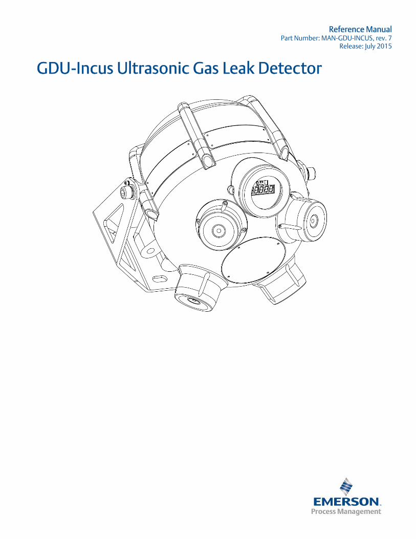
Reference Manual Part Number: MAN-GDU-INCUS, rev. 7
Release: July 2015
GDU-Incus Ultrasonic Gas Leak Detector

Important Instructions
Emerson Process Management designs, manufactures and tests products to function within specific conditions. Because these products are sophisticated technical instruments, it is important that the owner and operation personnel must strictly adhere both to the information printed on the product nameplate and to all instructions provided in this manual prior to installation, operation, and maintenance.
Installing, operating or maintaining an Emerson Process Management Product improperly could lead to serious injury or death from explosion or exposure to dangerous substances. Comply with all information on the product, in this manual, and in any local and national codes that apply to the product. Do not allow untrained personnel to work with this product. Use Emerson Process Management parts and work procedures specified in this manual.
In-depth specialist knowledge is an absolutely necessary condition for working with and on the GDU-Incus.
Authorized personnel for installing, operating, servicing and maintaining the GDU-Incus are instructed and trained qualified personnel of the operating company and the manufacturer.
It is the responsibility of the operating company to;
• train staff,
• observe safety regulations
• follow the instruction manual
Operators must;
• have been trained
• have read and understood all relevant sections of the instruction manual before commencing work
• know the safety mechanisms and regulations
To avoid personal injury and loss of property, do not install, operate, maintain or service this instrument before reading and understanding this instruction manual and receiving appropriate training
HEAVY INSTRUMENT! The GDU-Incus weighs 22 kg (49 lb) and therefore care must be taken when lifting and carrying the unit. Ensure all bolts and fixings selected for mounting are suitable for the weight and that the wall, pole, or mounting surface is solid and stable.

Notice
The contents of this publication are presented for informational purposes only, and while every effort has been made to ensure their accuracy, they are not to be construed as warranties or guarantees, expressed or implied, regarding the products or services described herein or their use or applicability. All sales are governed by Emerson Process Management’s terms and conditions, which are available upon request. We reserve the right to modify or improve the designs or specifications of such products at any time.
Emerson Process Management does not assume responsibility for the selection, use or maintenance of any product. Responsibility for proper selection, use and maintenance of any Emerson Process Management product(s) remains solely with the purchaser and end-user.
To the best of Emerson Process Management’s knowledge the information herein is complete and accurate. Emerson Process Management makes no warranties, expressed or implied, including implied warranties of merchantability and fitness for a particular purpose with respect to this manual and, in no event, shall Emerson Process Management be liable for any incidental, punitive, special or consequential damages including, but not limited to, loss of production, loss of profits, loss of revenue or use and costs incurred including without limitation for capital, fuel and power, and claims of third parties.
Product names used herein are for manufacturer or supplier identification only and may be trademarks/registered trademarks of these companies.
The Emerson logo is a trademark and service mark of the Emerson Electric Company.
Copyright © 2015 by Emerson Process Management, Slough, Berkshire, United Kingdom
All rights reserved. No part of this work may be reproduced or copied in any form or by any means - graphic, electronic, or mechanical without first receiving written permission of Emerson Process Management, Slough, Berkshire, United Kingdom.
Warranty
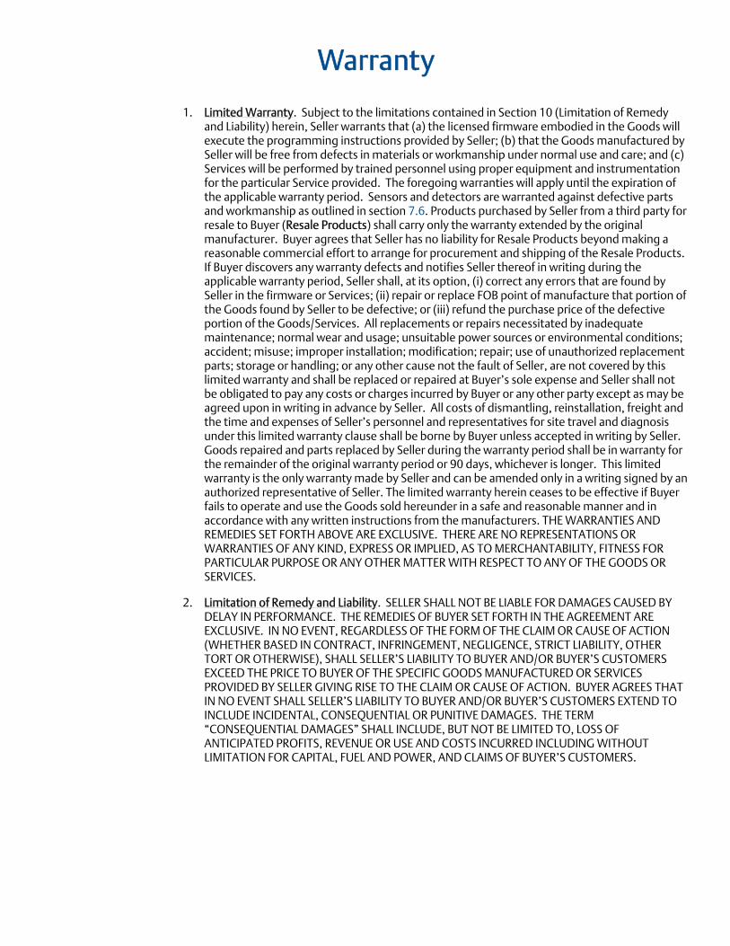
1. Limited Warranty. Subject to the limitations contained in Section 10 (Limitation of Remedy and Liability) herein, Seller warrants that (a) the licensed firmware embodied in the Goods will execute the programming instructions provided by Seller; (b) that the Goods manufactured by Seller will be free from defects in materials or workmanship under normal use and care; and (c) Services will be performed by trained personnel using proper equipment and instrumentation for the particular Service provided. The foregoing warranties will apply until the expiration of the applicable warranty period. Sensors and detectors are warranted against defective parts and workmanship as outlined in section 7.6. Products purchased by Seller from a third party for resale to Buyer (Resale Products) shall carry only the warranty extended by the original manufacturer. Buyer agrees that Seller has no liability for Resale Products beyond making a reasonable commercial effort to arrange for procurement and shipping of the Resale Products. If Buyer discovers any warranty defects and notifies Seller thereof in writing during the applicable warranty period, Seller shall, at its option, (i) correct any errors that are found by Seller in the firmware or Services; (ii) repair or replace FOB point of manufacture that portion of the Goods found by Seller to be defective; or (iii) refund the purchase price of the defective portion of the Goods/Services. All replacements or repairs necessitated by inadequate maintenance; normal wear and usage; unsuitable power sources or environmental conditions; accident; misuse; improper installation; modification; repair; use of unauthorized replacement parts; storage or handling; or any other cause not the fault of Seller, are not covered by this limited warranty and shall be replaced or repaired at Buyer’s sole expense and Seller shall not be obligated to pay any costs or charges incurred by Buyer or any other party except as may be agreed upon in writing in advance by Seller. All costs of dismantling, reinstallation, freight and the time and expenses of Seller’s personnel and representatives for site travel and diagnosis under this limited warranty clause shall be borne by Buyer unless accepted in writing by Seller. Goods repaired and parts replaced by Seller during the warranty period shall be in warranty for the remainder of the original warranty period or 90 days, whichever is longer. This limited warranty is the only warranty made by Seller and can be amended only in a writing signed by an authorized representative of Seller. The limited warranty herein ceases to be effective if Buyer fails to operate and use the Goods sold hereunder in a safe and reasonable manner and in accordance with any written instructions from the manufacturers. THE WARRANTIES AND REMEDIES SET FORTH ABOVE ARE EXCLUSIVE. THERE ARE NO REPRESENTATIONS OR WARRANTIES OF ANY KIND, EXPRESS OR IMPLIED, AS TO MERCHANTABILITY, FITNESS FOR PARTICULAR PURPOSE OR ANY OTHER MATTER WITH RESPECT TO ANY OF THE GOODS OR SERVICES.
2. Limitation of Remedy and Liability. SELLER SHALL NOT BE LIABLE FOR DAMAGES CAUSED BY DELAY IN PERFORMANCE. THE REMEDIES OF BUYER SET FORTH IN THE AGREEMENT ARE EXCLUSIVE. IN NO EVENT, REGARDLESS OF THE FORM OF THE CLAIM OR CAUSE OF ACTION (WHETHER BASED IN CONTRACT, INFRINGEMENT, NEGLIGENCE, STRICT LIABILITY, OTHER TORT OR OTHERWISE), SHALL SELLER’S LIABILITY TO BUYER AND/OR BUYER’S CUSTOMERS EXCEED THE PRICE TO BUYER OF THE SPECIFIC GOODS MANUFACTURED OR SERVICES PROVIDED BY SELLER GIVING RISE TO THE CLAIM OR CAUSE OF ACTION. BUYER AGREES THAT IN NO EVENT SHALL SELLER’S LIABILITY TO BUYER AND/OR BUYER’S CUSTOMERS EXTEND TO INCLUDE INCIDENTAL, CONSEQUENTIAL OR PUNITIVE DAMAGES. THE TERM “CONSEQUENTIAL DAMAGES” SHALL INCLUDE, BUT NOT BE LIMITED TO, LOSS OF ANTICIPATED PROFITS, REVENUE OR USE AND COSTS INCURRED INCLUDING WITHOUT LIMITATION FOR CAPITAL, FUEL AND POWER, AND CLAIMS OF BUYER’S CUSTOMERS.

Reference Manual Table of Contents MAN-GDU-INCUS Revision 7 July 2015
Table of Contents I
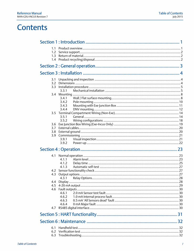
Contents
Section 1 : Introduction ............................................................................ 1
1.1 Product overview ................................................................................................................ 1 1.2 Service support ................................................................................................................... 2 1.3 Return of material ............................................................................................................... 2 1.4 Product recycling/disposal .................................................................................................. 2
Section 2 : General operation .................................................................... 3
Section 3 : Installation .............................................................................. 4
3.1 Unpacking and inspection .................................................................................................. 4 3.2 Dimensions ........................................................................................................................ 4 3.3 Installation procedure ......................................................................................................... 5
3.3.1 Mechanical installation ...................................................................................... 5 3.4 Mounting ........................................................................................................................... 8
3.4.1 Wall / Flat surface mounting ............................................................................... 8 3.4.2 Pole mounting ................................................................................................. 10 3.4.3 Mounting with Exe Junction Box ....................................................................... 11 3.4.4 DNV mounting ................................................................................................. 12
3.5 Terminal Compartment Wiring (Non-Exe) ......................................................................... 14 3.5.1 General ............................................................................................................ 14 3.5.2 Wiring configurations ...................................................................................... 18
3.6 Exe Junction Box Wiring (Exe-Incus Only) .......................................................................... 19 3.7 External cables .................................................................................................................. 20 3.8 External ground ................................................................................................................ 20 3.9 Commissioning ................................................................................................................ 21
3.9.1 Visual inspection .............................................................................................. 21 3.9.2 Power-up ......................................................................................................... 22
Section 4 : Operation .............................................................................. 23
4.1 Normal operation ............................................................................................................. 23 4.1.1 Alarm level ....................................................................................................... 23 4.1.2 Delay time ....................................................................................................... 25 4.1.3 Automatic self-test .......................................................................................... 27
4.2 Sensor functionality check ................................................................................................ 27 4.3 Output options ................................................................................................................. 27
4.3.1 Relay Options ................................................................................................... 28 4.4 Display ............................................................................................................................. 28 4.5 4-20 mA output ................................................................................................................ 29 4.6 Fault outputs .................................................................................................................... 30
4.6.1 2.0 mA Sensor test fault ................................................................................... 30 4.6.2 1.0 mA Internal process fault ............................................................................ 30 4.6.3 0.5 mA ‘All Sensors dead’ fault ......................................................................... 30 4.6.4 0 mA Major fault .............................................................................................. 30
4.7 RS485 digital interface ...................................................................................................... 30
Section 5 : HART functionality ................................................................. 31
Section 6 : Maintenance ......................................................................... 32
6.1 Handheld test ................................................................................................................... 32 6.2 Verification test ................................................................................................................ 32 6.3 Troubleshooting ............................................................................................................... 32
Reference Manual July 2015 MAN-GDU-INCUS, Revision 7
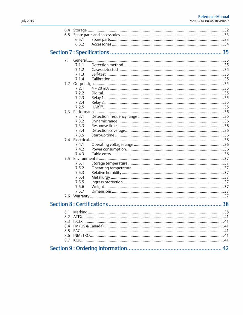
6.4 Storage ............................................................................................................................ 32 6.5 Spare parts and accessories .............................................................................................. 33
6.5.1 Spare parts ....................................................................................................... 33 6.5.2 Accessories ...................................................................................................... 34
Section 7 : Specifications ........................................................................ 35
7.1 General............................................................................................................................. 35 7.1.1 Detection method ........................................................................................... 35 7.1.2 Gases detected ................................................................................................ 35 7.1.3 Self-test ........................................................................................................... 35 7.1.4 Calibration ....................................................................................................... 35
7.2 Output signal .................................................................................................................... 35 7.2.1 4 — 20 mA ........................................................................................................ 35 7.2.2 Digital .............................................................................................................. 35 7.2.3 Relay 1 ............................................................................................................. 35 7.2.4 Relay 2 ............................................................................................................. 35 7.2.5 HART® .............................................................................................................. 35
7.3 Performance ..................................................................................................................... 36 7.3.1 Detection frequency range .............................................................................. 36 7.3.2 Dynamic range ................................................................................................. 36 7.3.3 Response time ................................................................................................. 36 7.3.4 Detection coverage.......................................................................................... 36 7.3.5 Start-up time ................................................................................................... 36
7.4 Electrical ........................................................................................................................... 36 7.4.1 Operating voltage range .................................................................................. 36 7.4.2 Power consumption ......................................................................................... 36 7.4.3 Cable entry ...................................................................................................... 36
7.5 Environmental .................................................................................................................. 37 7.5.1 Storage temperature ....................................................................................... 37 7.5.2 Operating temperature .................................................................................... 37 7.5.3 Relative humidity ............................................................................................. 37 7.5.4 Metallurgy ....................................................................................................... 37 7.5.5 Ingress protection ............................................................................................ 37 7.5.6 Weight ............................................................................................................. 37 7.5.7 Dimensions ...................................................................................................... 37
7.6 Warranty .......................................................................................................................... 37
Section 8 : Certifications ......................................................................... 38
8.1 Marking ............................................................................................................................ 38 8.2 ATEX................................................................................................................................. 41 8.3 IECEx ................................................................................................................................ 41 8.4 FM (US & Canada) ............................................................................................................. 41 8.5 EAC .................................................................................................................................. 41 8.6 INMETRO .......................................................................................................................... 41 8.7 KCs ................................................................................................................................... 41
Section 9 : Ordering information ............................................................. 42
Reference Manual MAN-GDU-INCUS, Revision 7 July 2015
1
Section 1: Introduction 1.1 Product overview
The GDU-Incus is an ultrasonic gas leak detector used for detecting airborne ultrasound generated from pressurized gas leaks.
Airborne ultrasound is generated when gas moves from a high-pressure area to a low pressure area with a ratio in excess of 1.8:1 upstream to downstream, however, the GDU-Incus is only recommended for pressures above 2 bar (30 psi) Gauge. The intensity of airborne ultrasound generated is dependent on a number of factors including but not limited to gas pressure, leak size and gas temperature.
The GDU-Incus uses 4 individual Piezo ceramic sensing heads designed using a Patent pending floating crystal design. The sensor design makes the sensing heads virtually indestructible and totally immune to temperature, moisture, and other contaminants found in hazardous industry. The GDU-Incus uses a continuous electronic monitoring test feature to ensure complete functionality.
The GDU-Incus has a large dynamic range which allows use in a wide range of applications from offshore platforms to gas transportation systems. The multi-stage amplifier ensures a linear output across the entire detector range without drop-off at each end of the range.
The GDU-Incus is not designed to detect specific gas types, LEL or ppm, but instead responds instantaneously to the ultrasound produced by a wide range of leak sizes while being unaffected by even the most extreme weather conditions. The GDU-Incus is rated to IP66/IP67, NEMA Type 4X to withstand harsh environments.
The GDU-Incus is supplied with a 4-20 mA analog output, ‘multi-drop’ RS485 digital interface and a HART® interface.
Reference Manual July 2015 MAN-GDU-INCUS, Revision 7
2
1.2 Service support Technical support for this product can be provided by contacting your local Emerson Process Management sales office or by contacting the Technical Support department at [email protected]
1.3 Return of material To expedite the repair and return of this product, proper communication between the customer and the factory is important. Before returning a product for repair, e-mail [email protected] for a Return Material Authorization (RMA) number.
On the return of the equipment, include the following information:
1. RMA number provided to you by Emerson Process Management 2. Company name and contact information 3. Purchase order, from your company, authorizing repairs or request for quote 4. Ship all equipment, prepaid to:
Emerson Process Management 158 Edinburgh Avenue Slough Berkshire SL1 4UE, UK
5. Mark all packages with Return for Repair and include RMA number
Pack items to protect them from damage and use anti-static bags or aluminum-backed cardboard as protection from electrostatic damage.
All equipment must be shipped prepaid. Collect shipments will not be accepted.
1.4 Product recycling/disposal Recycling of equipment and packaging should be taken into consideration and disposed of in accordance with local and national legislations/regulations.
Reference Manual MAN-GDU-INCUS, Revision 7 July 2015
3
Section 2: General operation The GDU-Incus is omni-directional and is recommended to be mounted between 3 to 5 meters (10 to 16 feet) above the area of interest to eliminate ground absorption and reflections.
It is recommended that the area where the GDU-Incus is to be situated is ultrasonically mapped prior to installation or at commissioning while all processes are running to establish a background noise level for alarm purposes. The alarm level should be set above the background noise level. Please contact an Emerson Process Management representative to request a mapping survey or mapping tools.
The GDU-Incus responds instantaneously to pressurized gas leaks or other sources of ultrasonic noise between 25 kHz and 100 kHz. It is, therefore, recommended that a delay time is built in to the control system or alternatively, programmed in the GDU-Incus when using it in standalone mode to prevent spurious alarms. The delay time is recommended to be set at a minimum of fifteen (15) seconds but this should be increased in response to the process located near to the detector as shown in the graph in section 4.1.2.
The maximum area which can be monitored by a single GDU-Incus is affected by several factors such as background (ambient) ultrasound level, gas pressure, leak size, temperature of the gas, and environmental conditions. Emerson Process Management has formulated a series of calculations that take all of these external factors into account and are able to determine accurate coverage information for most installations. Please contact an Emerson Process Management representative to advise on appropriate coverage for each installation.
The GDU-Incus detection coverage can be verified at installation or as part of a maintenance schedule using the GDU-PTV Performance Target Verification Kit to simulate an actual gas release of known size and pressure at the perimeter of the GDU-Incus detection radius. See section 6.5 for a listing of spare parts and accessories or contact an Emerson Process Management representative for further details.
Compared to other Ultrasonic and traditional forms of detection, the GDU-Incus has the following advantages:
Gas does not need to reach the sensor for detection to occur
Unaffected by weather conditions
Sensors are unaffected by temperature, pressure, moisture, and contaminant build-up
Multiple sensor redundancy in each unit
Continuous self-test function
No calibration required results in cost saving over detector lifecycle
Can be remotely tested from up to 8 meter distance saving on maintenance scaffold costs
4-20 mA Current Loop with HART communication as standard, plus relay outputs for ‘Fault’ and ‘Alarm’ conditions.
Can operate standalone or as part of an interfaced control system.
Reference Manual July 2015 MAN-GDU-INCUS, Revision 7
4
Section 3: Installation
The area in which the detector may be mounted must be in accordance with the certification of the apparatus and in accordance with the standards of the appropriate authority in the country concerned.
Do not modify the enclosure or component parts as this will compromise the Hazardous Area Certification.
Ensure all wiring and power supply to the detector is within specified operating parameters.
The GDU-Incus is a sealed unit with the exception of the terminal cover; the main enclosure is not to be opened by anybody other than Emerson Process Management or Emerson Process Management authorized personnel. All warranties and certification are nullified if these seals are broken or tampered with.
The GDU-Incus is supplied without cable glands. Ensure all cable entry threads are sealed with an appropriate plug to eliminate water ingress and thread damage. At installation, all shipping cable entry plugs are to be removed and replaced with suitably approved Ex d cable glands or blanking plugs to meet hazardous locations requirements. If the GDU-Incus is to be installed in a ‘Zone 1’ Hazardous Area an Exd barrier seal must be used.
Identification tags must be firmly secured to the GDU-Incus bracket in the position shown on Figure 3-1 to prevent unwanted locally generated ultrasonic noise.
3.1 Unpacking and inspection Carefully remove all of the components from the packaging and verify them against the enclosed packing list. Inspect all components for obvious damage such as broken or loose parts. If you find any components missing or damaged, notify your local Emerson Process Management representative or the factory immediately.
3.2 Dimensions Refer to Figure 3-1 for the dimensions of the GDU-Incus. Note: all dimensions are provided in millimeters.

Reference Manual MAN-GDU-INCUS, Revision 7 July 2015
5
Figure 3-1 Dimensions
3.3 Installation procedure Mounting height of the GDU-Incus is recommended to be between 3 and 5 meters (10 to 16 feet) above the floor level to eliminate ground reflections and absorption. The GDU-Incus may be used lower than 3 meters (10 feet) but coverage may be reduced, please contact an Emerson Process Management representative for more details.
Observe the area of installation for equipment capable of generating high levels of spurious airborne noise that would not be classified as “normal background noise” such as pressure release valves, etc. If any are present in the detector range of coverage, please contact Emerson Process Management or monitor the detector when activated to ensure immunity.
3.3.1 Mechanical installation The GDU-Incus incorporates a dedicated flameproof terminal compartment certified to Ex d, and a flameproof main electronics compartment certified to Ex d both sealed to IP66/IP67. Care should be taken when removing the terminal cover during installation to ensure that the flamepath surfaces are not scratched or damaged.
The GDU-Incus has a large detection radius capability and care should be taken when positioning to utilise the maximum coverage while eliminating blind spots and spurious alarms.
Reference Manual July 2015 MAN-GDU-INCUS, Revision 7
6
The GDU-Incus has a variety of mounting options to incorporate installation into most situations found in industrial environments such as wall / flat surface mounting (refer to section 3.4.1), vertical pole mounting (refer to section 3.4.2), and mounting in an environment where DNV certification is required (refer to section 3.4.4).
The GDU-Incus can be mounted in any orientation (unless a DNV bracket is used which fixes the detector in vertical orientation) but care should be taken to position the display facing an area where the information can be easily viewed.
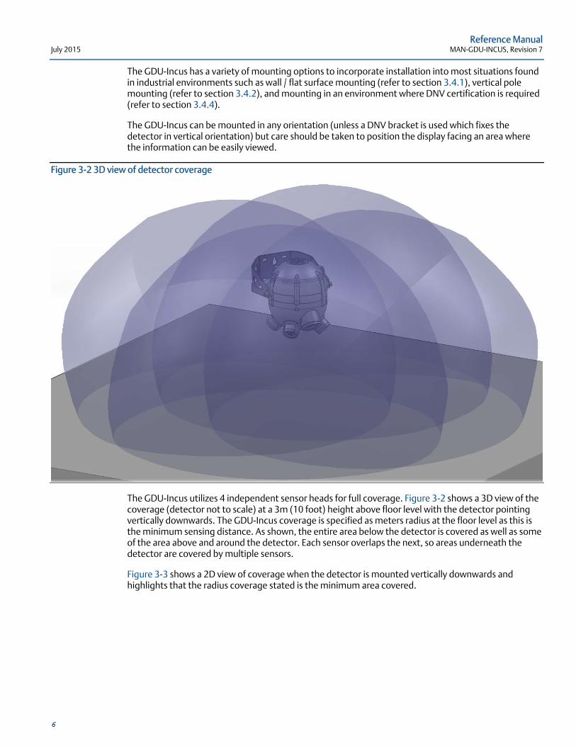
Figure 3-2 3D view of detector coverage
The GDU-Incus utilizes 4 independent sensor heads for full coverage. Figure 3-2 shows a 3D view of the coverage (detector not to scale) at a 3m (10 foot) height above floor level with the detector pointing vertically downwards. The GDU-Incus coverage is specified as meters radius at the floor level as this is the minimum sensing distance. As shown, the entire area below the detector is covered as well as some of the area above and around the detector. Each sensor overlaps the next, so areas underneath the detector are covered by multiple sensors.
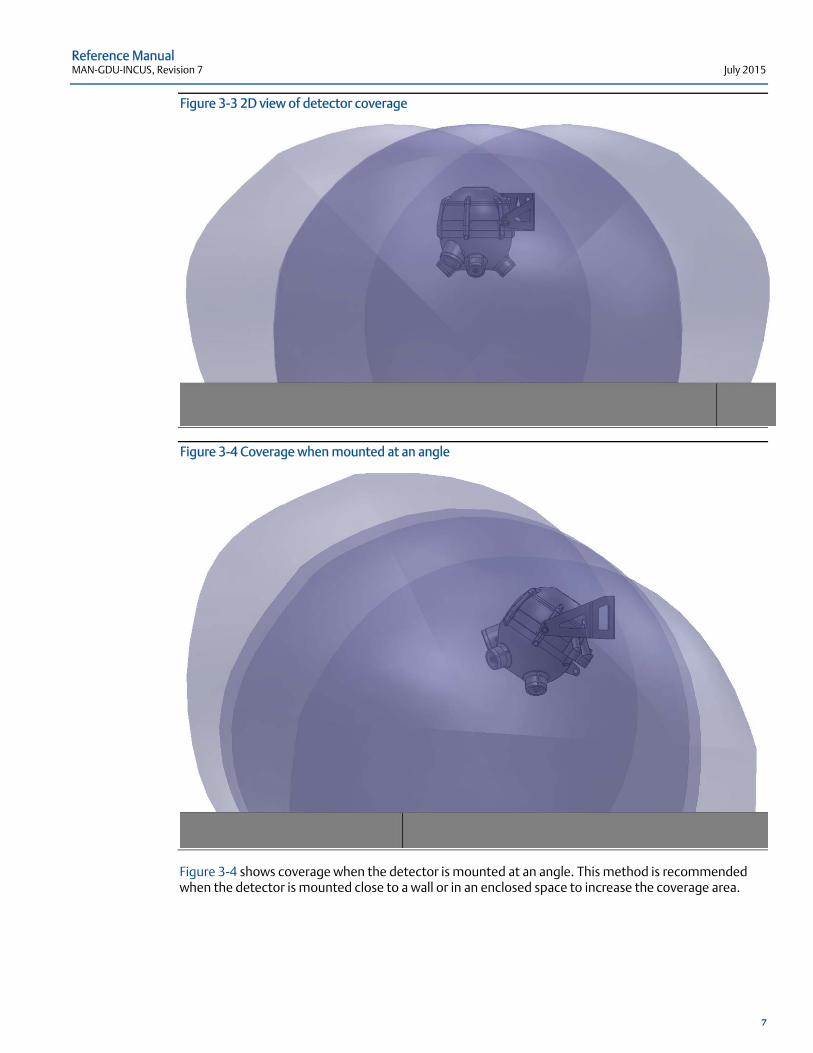
Figure 3-3 shows a 2D view of coverage when the detector is mounted vertically downwards and highlights that the radius coverage stated is the minimum area covered.
Reference Manual MAN-GDU-INCUS, Revision 7 July 2015
7
Figure 3-3 2D view of detector coverage
Figure 3-4 Coverage when mounted at an angle
Figure 3-4 shows coverage when the detector is mounted at an angle. This method is recommended when the detector is mounted close to a wall or in an enclosed space to increase the coverage area.
Reference Manual July 2015 MAN-GDU-INCUS, Revision 7
8
3.4 Mounting
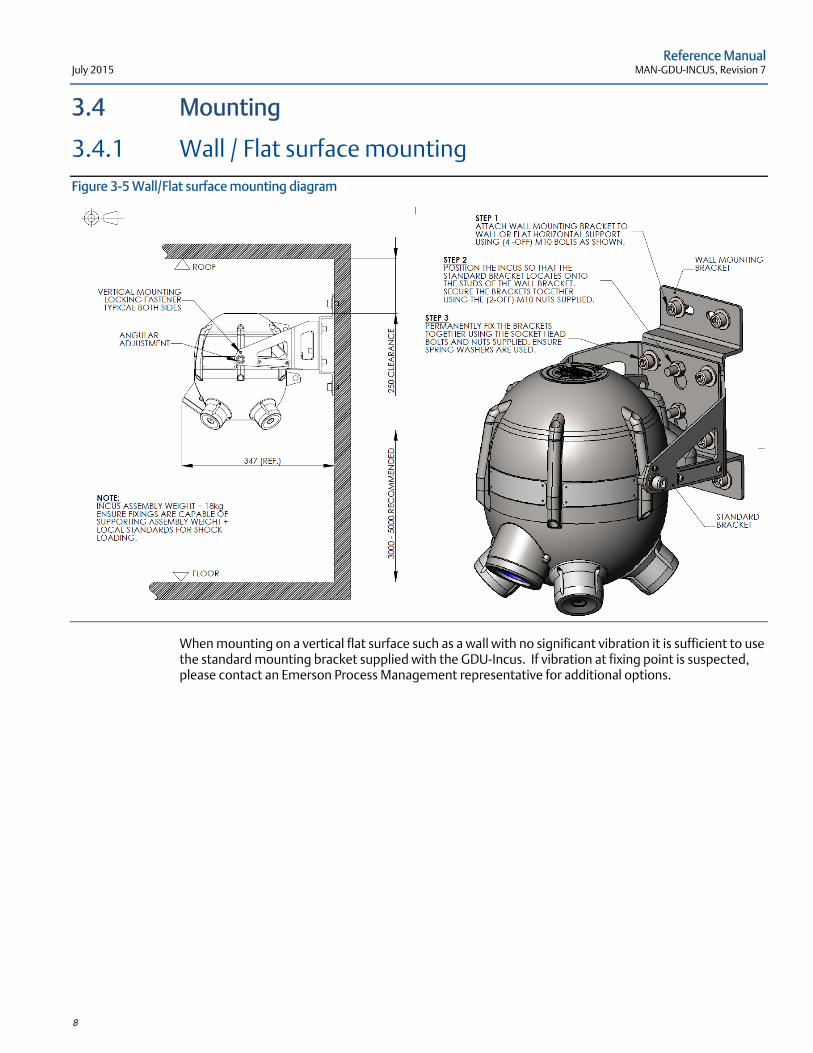
3.4.1 Wall / Flat surface mounting Figure 3-5 Wall/Flat surface mounting diagram
When mounting on a vertical flat surface such as a wall with no significant vibration it is sufficient to use the standard mounting bracket supplied with the GDU-Incus. If vibration at fixing point is suspected, please contact an Emerson Process Management representative for additional options.
Reference Manual MAN-GDU-INCUS, Revision 7 July 2015
9
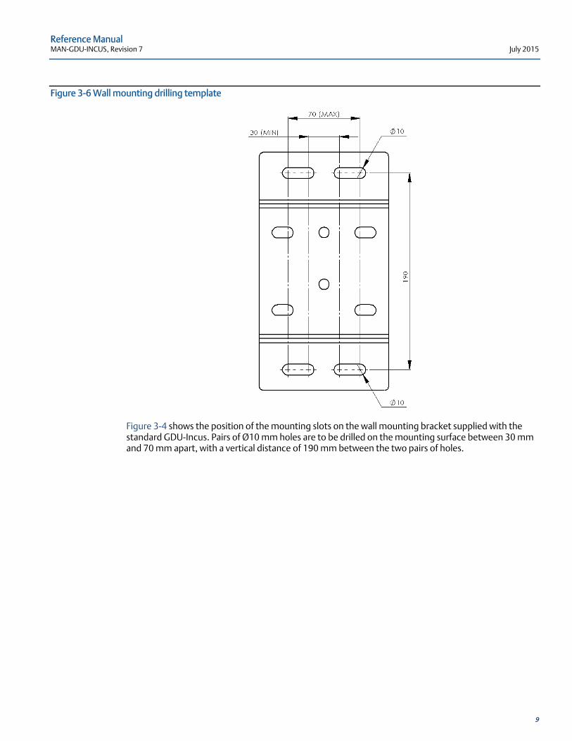
Figure 3-6 Wall mounting drilling template
Figure 3-4 shows the position of the mounting slots on the wall mounting bracket supplied with the standard GDU-Incus. Pairs of Ø10 mm holes are to be drilled on the mounting surface between 30 mm and 70 mm apart, with a vertical distance of 190 mm between the two pairs of holes.
Reference Manual July 2015 MAN-GDU-INCUS, Revision 7
10
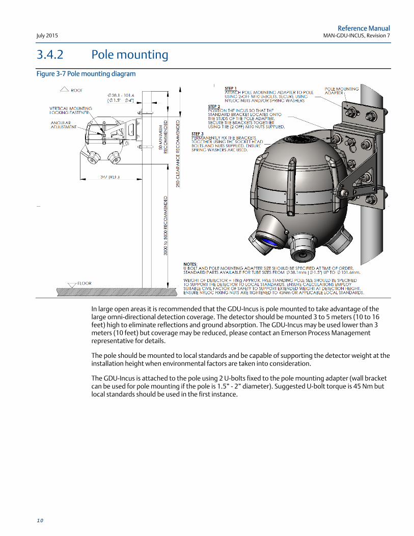
3.4.2 Pole mounting Figure 3-7 Pole mounting diagram
In large open areas it is recommended that the GDU-Incus is pole mounted to take advantage of the large omni-directional detection coverage. The detector should be mounted 3 to 5 meters (10 to 16 feet) high to eliminate reflections and ground absorption. The GDU-Incus may be used lower than 3 meters (10 feet) but coverage may be reduced, please contact an Emerson Process Management representative for details.
The pole should be mounted to local standards and be capable of supporting the detector weight at the installation height when environmental factors are taken into consideration.
The GDU-Incus is attached to the pole using 2 U-bolts fixed to the pole mounting adapter (wall bracket can be used for pole mounting if the pole is 1.5” - 2” diameter). Suggested U-bolt torque is 45 Nm but local standards should be used in the first instance.
Reference Manual MAN-GDU-INCUS, Revision 7 July 2015
11
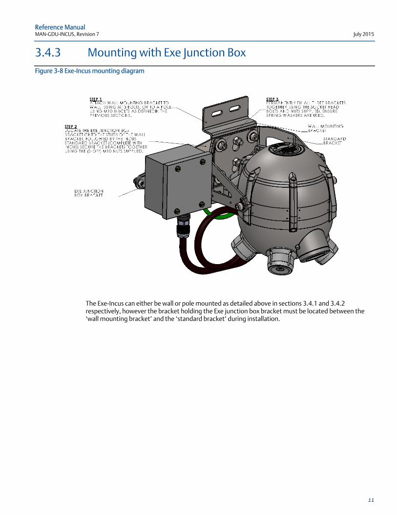
3.4.3 Mounting with Exe Junction Box Figure 3-8 Exe-Incus mounting diagram
The Exe-Incus can either be wall or pole mounted as detailed above in sections 3.4.1 and 3.4.2 respectively, however the bracket holding the Exe junction box bracket must be located between the ‘wall mounting bracket’ and the ‘standard bracket’ during installation.
Reference Manual July 2015 MAN-GDU-INCUS, Revision 7
12
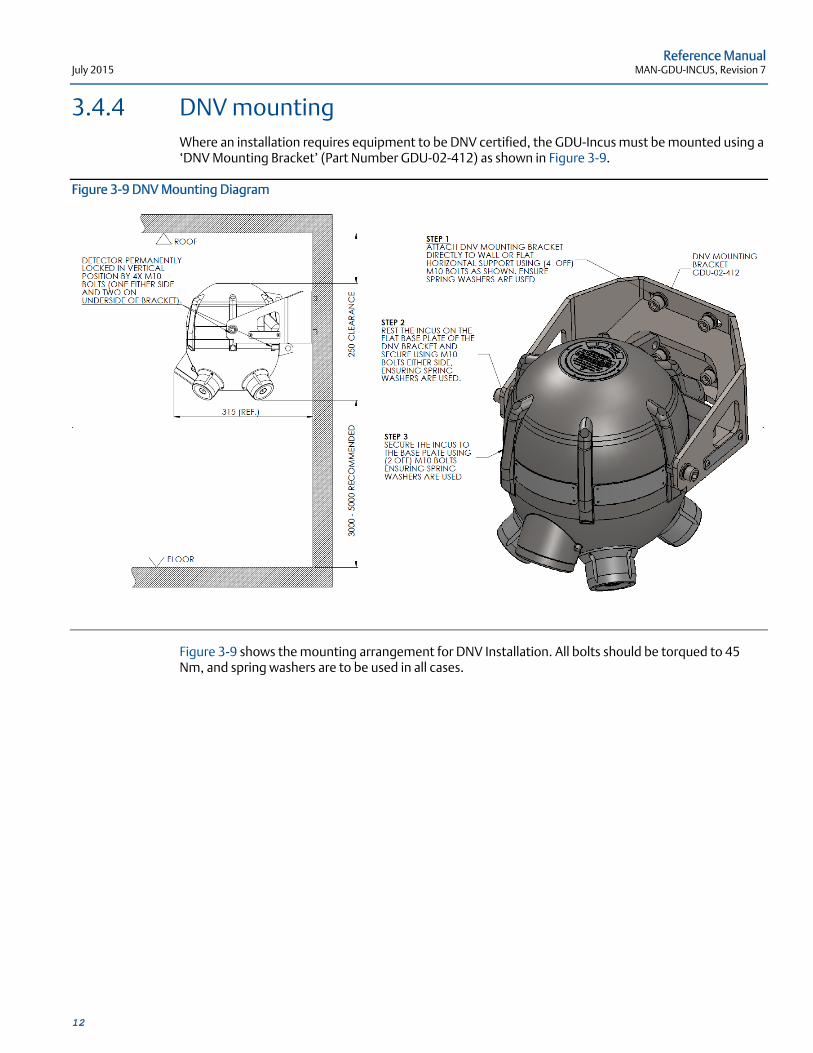
3.4.4 DNV mounting Where an installation requires equipment to be DNV certified, the GDU-Incus must be mounted using a ‘DNV Mounting Bracket’ (Part Number GDU-02-412) as shown in Figure 3-9.
Figure 3-9 DNV Mounting Diagram
Figure 3-9 shows the mounting arrangement for DNV Installation. All bolts should be torqued to 45 Nm, and spring washers are to be used in all cases.
Reference Manual MAN-GDU-INCUS, Revision 7 July 2015
13
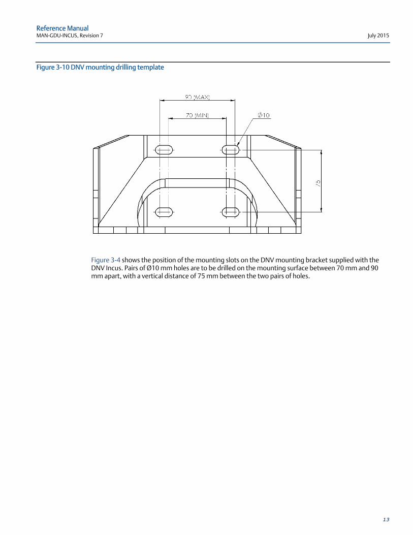
Figure 3-10 DNV mounting drilling template
Figure 3-4 shows the position of the mounting slots on the DNV mounting bracket supplied with the DNV Incus. Pairs of Ø10 mm holes are to be drilled on the mounting surface between 70 mm and 90 mm apart, with a vertical distance of 75 mm between the two pairs of holes.
Reference Manual July 2015 MAN-GDU-INCUS, Revision 7
14
3.5 Terminal Compartment Wiring (Non-Exe)
Failure to follow these installation guidelines could result in death or serious injury. Ensure that only qualified personnel perform the installation.
Electrical shock could cause death or serious injury. Use extreme caution when making contact with the leads and terminals.
Do not open the GDU-Incus enclosure when in a classified area or when an explosive atmosphere may be present unless the power to the GDU-Incus has been removed.
The GDU-Incus terminal cover is certified to flameproof standards and should not be opened while energized.
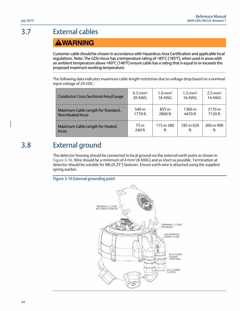
The detector housing should be connected to local ground via the external earth point as shown in Figure 3-16. The ground wire should be minimum of 4 mm² (8 AWG) and as short as possible. Termination at detector should be suitable for M6 (0.25”) fastener. Ensure earth wire is attached using the supplied spring washer.
The standard GDU-Incus is temperature rated between -40°C and +85°C (-40°F and +185°F), and the heated variant is temperature rated between -55°C and +85°C (-67°F and +185°F). Ensure that all cable is rated to the appropriate temperature of installation.
3.5.1 General
Wiring codes and regulations may vary. Wiring must comply with all applicable regulations relating to the installation of electrical equipment in a hazardous area and is the responsibility of the installer. If in doubt, consult a qualified official before wiring the system.
In applications where the wiring is installed in conduit, the conduit must not be used for wiring to other equipment.
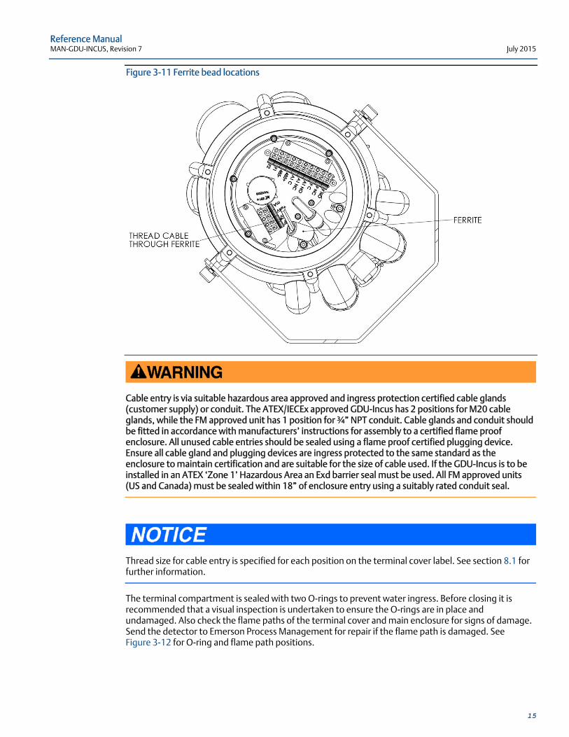
For full EMC compliance ensure incoming cables are threaded through the ferrite beads (provided with unit), see Figure 3-11.
To gain access to the terminal compartment, undo the six terminal cover fixing screws and raise the terminal cover vertically until clear of the main enclosure. The terminal cover is held in place by means of a stainless steel wire. The terminal cover can be lowered to the side of the detector during installation but care should be taken to ensure the flamepath is not damaged. Refer to Figure 3-12 for flamepath details. Tighten the six terminal cover fixing screws to a torque of 9 Nm.
Reference Manual MAN-GDU-INCUS, Revision 7 July 2015
15
Figure 3-11 Ferrite bead locations
Cable entry is via suitable hazardous area approved and ingress protection certified cable glands (customer supply) or conduit. The ATEX/IECEx approved GDU-Incus has 2 positions for M20 cable glands, while the FM approved unit has 1 position for ¾” NPT conduit. Cable glands and conduit should be fitted in accordance with manufacturers’ instructions for assembly to a certified flame proof enclosure. All unused cable entries should be sealed using a flame proof certified plugging device. Ensure all cable gland and plugging devices are ingress protected to the same standard as the enclosure to maintain certification and are suitable for the size of cable used. If the GDU-Incus is to be installed in an ATEX ‘Zone 1’ Hazardous Area an Exd barrier seal must be used. All FM approved units (US and Canada) must be sealed within 18” of enclosure entry using a suitably rated conduit seal.
Thread size for cable entry is specified for each position on the terminal cover label. See section 8.1 for further information.
The terminal compartment is sealed with two O-rings to prevent water ingress. Before closing it is recommended that a visual inspection is undertaken to ensure the O-rings are in place and undamaged. Also check the flame paths of the terminal cover and main enclosure for signs of damage. Send the detector to Emerson Process Management for repair if the flame path is damaged. See Figure 3-12 for O-ring and flame path positions.
Reference Manual July 2015 MAN-GDU-INCUS, Revision 7
16
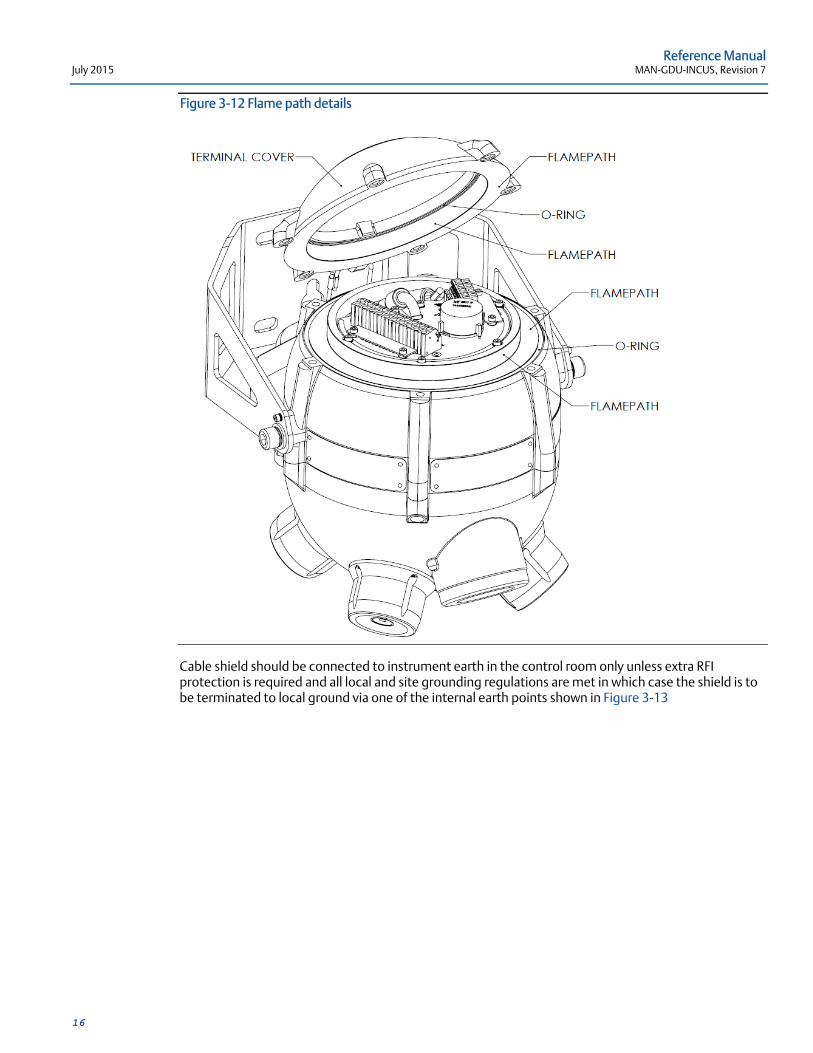
Figure 3-12 Flame path details
Cable shield should be connected to instrument earth in the control room only unless extra RFI protection is required and all local and site grounding regulations are met in which case the shield is to be terminated to local ground via one of the internal earth points shown in Figure 3-13
Reference Manual MAN-GDU-INCUS, Revision 7 July 2015
17
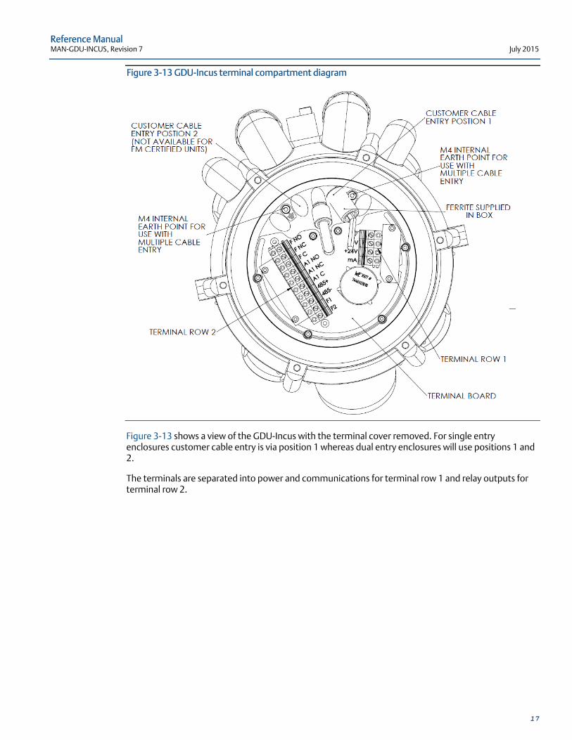
Figure 3-13 GDU-Incus terminal compartment diagram
Figure 3-13 shows a view of the GDU-Incus with the terminal cover removed. For single entry enclosures customer cable entry is via position 1 whereas dual entry enclosures will use positions 1 and 2.
The terminals are separated into power and communications for terminal row 1 and relay outputs for terminal row 2.
Reference Manual July 2015 MAN-GDU-INCUS, Revision 7
18
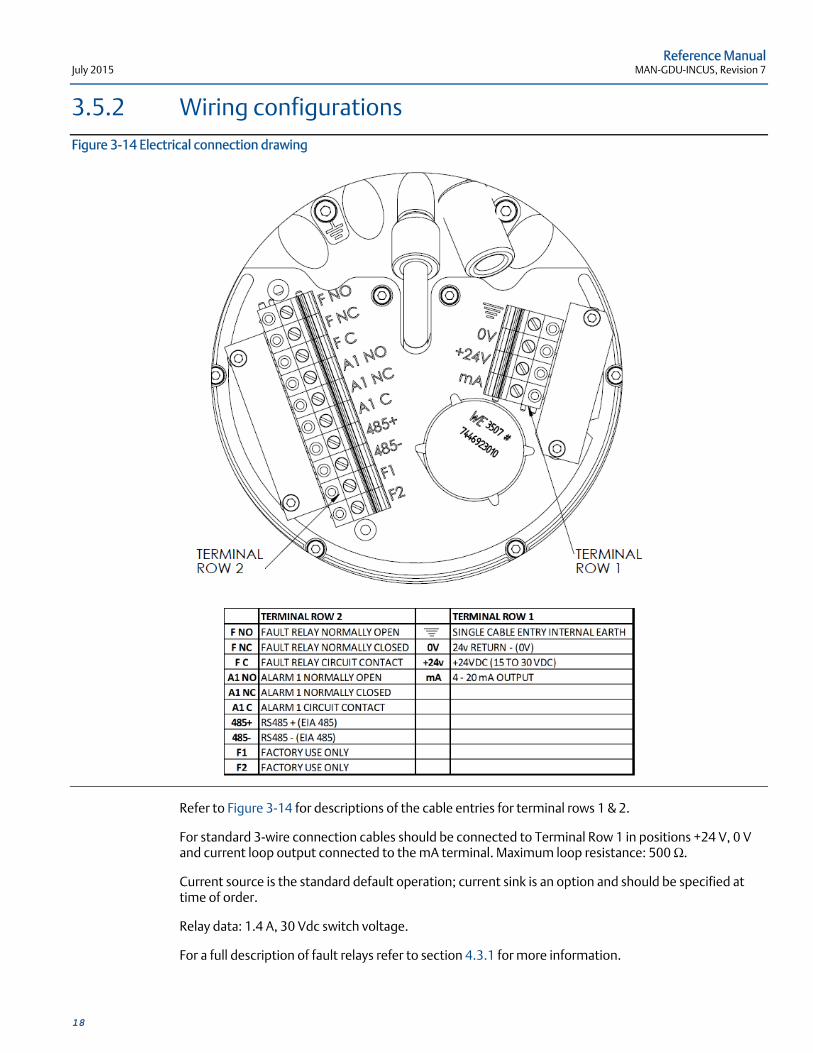
3.5.2 Wiring configurations Figure 3-14 Electrical connection drawing
Refer to Figure 3-14 for descriptions of the cable entries for terminal rows 1 & 2.
For standard 3-wire connection cables should be connected to Terminal Row 1 in positions +24 V, 0 V and current loop output connected to the mA terminal. Maximum loop resistance: 500 Ω.
Current source is the standard default operation; current sink is an option and should be specified at time of order.
Relay data: 1.4 A, 30 Vdc switch voltage.
For a full description of fault relays refer to section 4.3.1 for more information.

Reference Manual MAN-GDU-INCUS, Revision 7 July 2015
19
3.6 Exe Junction Box Wiring (Exe-Incus Only) The terminal compartment on the Exe-Incus unit is sealed at the factory and should not be opened on site. Instead, all wiring connections are made via the Exe junction box that is mounted adjacent to the Incus unit.
Figure 3-15 Exe Incus Electrical connection drawing
Refer to Figure 3-15 for descriptions of the cable entries for the terminals inside the Exe Junction box.
The Exe-Incus is configured for a standard 3-wire connection; cables should be connected in positions +24 V, 0 V and current loop output connected to the mA terminal.
Cable entry is via suitable hazardous area approved and ingress protection certified cable glands (customer supply) or conduit. Ensure cable glands are ingress protected to the same standard as the enclosure to maintain certification and are suitable for the size of cable used. Cable glands and conduit should be fitted in accordance with manufacturers’ instructions.
Reference Manual July 2015 MAN-GDU-INCUS, Revision 7
20
3.7 External cables
Customer cable should be chosen in accordance with Hazardous Area Certification and applicable local regulations. Note: The GDU-Incus has a temperature rating of +85°C (185°F), when used in areas with an ambient temperature above +60°C (140°F) ensure cable has a rating that is equal to or exceeds the proposed maximum working temperature.
The following data indicates maximum cable length restriction due to voltage drop based on a nominal input voltage of 24 VDC:
Conductor Cross Sectional Area/Gauge 0.5 mm² 20 AWG
1.0 mm² 18 AWG
1.5 mm² 16 AWG
2.5 mm² 14 AWG
Maximum Cable Length for Standard, Non-Heated Incus
540 m 1770 ft
855 m 2800 ft
1360 m 4470 ft
2170 m 7120 ft
Maximum Cable Length for Heated Incus
75 m 240 ft
115 m 380 ft
185 m 620 ft
300 m 990 ft
3.8 External ground The detector housing should be connected to local ground via the external earth point as shown in Figure 3-16. Wire should be a minimum of 4 mm² (8 AWG) and as short as possible. Termination at detector should be suitable for M6 (0.25”) fastener. Ensure earth wire is attached using the supplied spring washer.
Figure 3-16 External grounding point
Reference Manual MAN-GDU-INCUS, Revision 7 July 2015
21
3.9 Commissioning
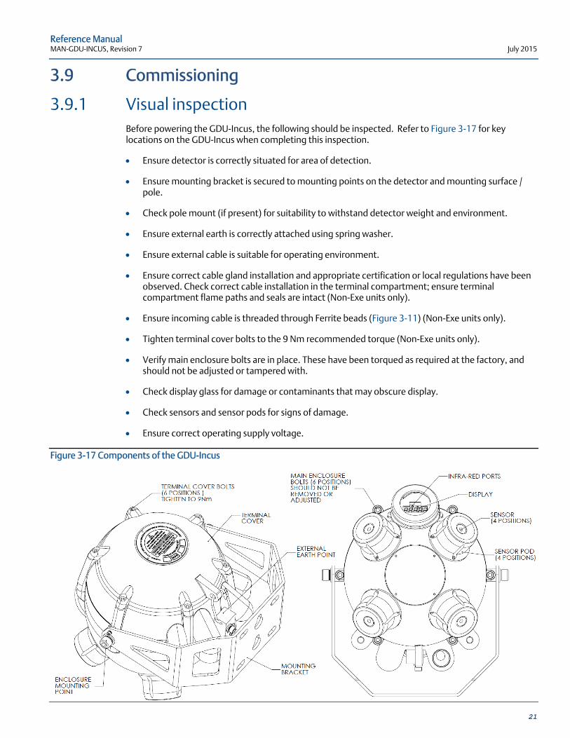
3.9.1 Visual inspection Before powering the GDU-Incus, the following should be inspected. Refer to Figure 3-17 for key locations on the GDU-Incus when completing this inspection.
Ensure detector is correctly situated for area of detection.
Ensure mounting bracket is secured to mounting points on the detector and mounting surface / pole.
Check pole mount (if present) for suitability to withstand detector weight and environment.
Ensure external earth is correctly attached using spring washer.
Ensure external cable is suitable for operating environment.
Ensure correct cable gland installation and appropriate certification or local regulations have been observed. Check correct cable installation in the terminal compartment; ensure terminal compartment flame paths and seals are intact (Non-Exe units only).
Ensure incoming cable is threaded through Ferrite beads (Figure 3-11) (Non-Exe units only).
Tighten terminal cover bolts to the 9 Nm recommended torque (Non-Exe units only).
Verify main enclosure bolts are in place. These have been torqued as required at the factory, and should not be adjusted or tampered with.
Check display glass for damage or contaminants that may obscure display.
Check sensors and sensor pods for signs of damage.
Ensure correct operating supply voltage.
Figure 3-17 Components of the GDU-Incus
Reference Manual July 2015 MAN-GDU-INCUS, Revision 7
22
3.9.2 Power-up Upon power-up a brief functionality check will run to ensure detector functionality, this lasts no more than five (5) seconds. Once completed, the GDU-Incus will go into normal operation using the factory/customer defaults specified at time of order or signal any faults that may be present. (Factory default options can be found in section 4.1 and a list of faults can be found in section 4.6).
In addition the display will show the real-time ultrasonic sound level and the detector will become responsive to RS485 commands for function setup and all relays will be energized or de-energized as per defaults.
Note: If the GDU-Incus has been factory set for specific site requirements it is recommended to carry out the steps outlined in section 4.2 before completion of commissioning.
Reference Manual MAN-GDU-INCUS, Revision 7 July 2015
23
Section 4: Operation 4.1 Normal operation
On power-up the GDU-Incus initializes a diagnostic check and then enters normal operation mode as per factory defaults supplied.
Factory Op mode 71 settings;
4-20 mA = 40-120 dB (Linear scale factor)
Display brightness set to 12. Viewing distance over 10 m (33 ft) in an outdoor environment
Real time instantaneous ultrasonic sound level shown on display in dB
Relays are energized open, loss of power causes alarm (fail-safe)
Relays are set to non-latching
Reset alarms enabled; allows latched relays to be reset and restarts alarm delay
Alarm level set at 70 dB for relay output
Delay time set to 15 seconds for relay output
RS485 ID set to 1
All communication ports are active and ready to receive commands
4.1.1 Alarm level The ‘Alarm Level’ is the ultrasonic sound level at which an alarm state is triggered. During the alarm state the display flashes, the relays switch states and the current loop becomes active if one or more sensors were in fault mode (if no sensors are in fault the current loop will already be outputting dB level).
To avoid false alarms it is recommended to set the alarm level above the background level established by mapping when all processes are operational. If the background level is unknown it is recommended to analyze the background using the detector itself. Care should be taken to observe all processes that may cause intermittent ultrasonic noise such as pressure relief valves.
Please contact an Emerson Process Management representative for advice on alarm levels.
Note: the higher the alarm level the smaller the detector coverage radius, it is therefore important to establish a safe alarm level at the lowest permissible value.
Reference Manual July 2015 MAN-GDU-INCUS, Revision 7
24
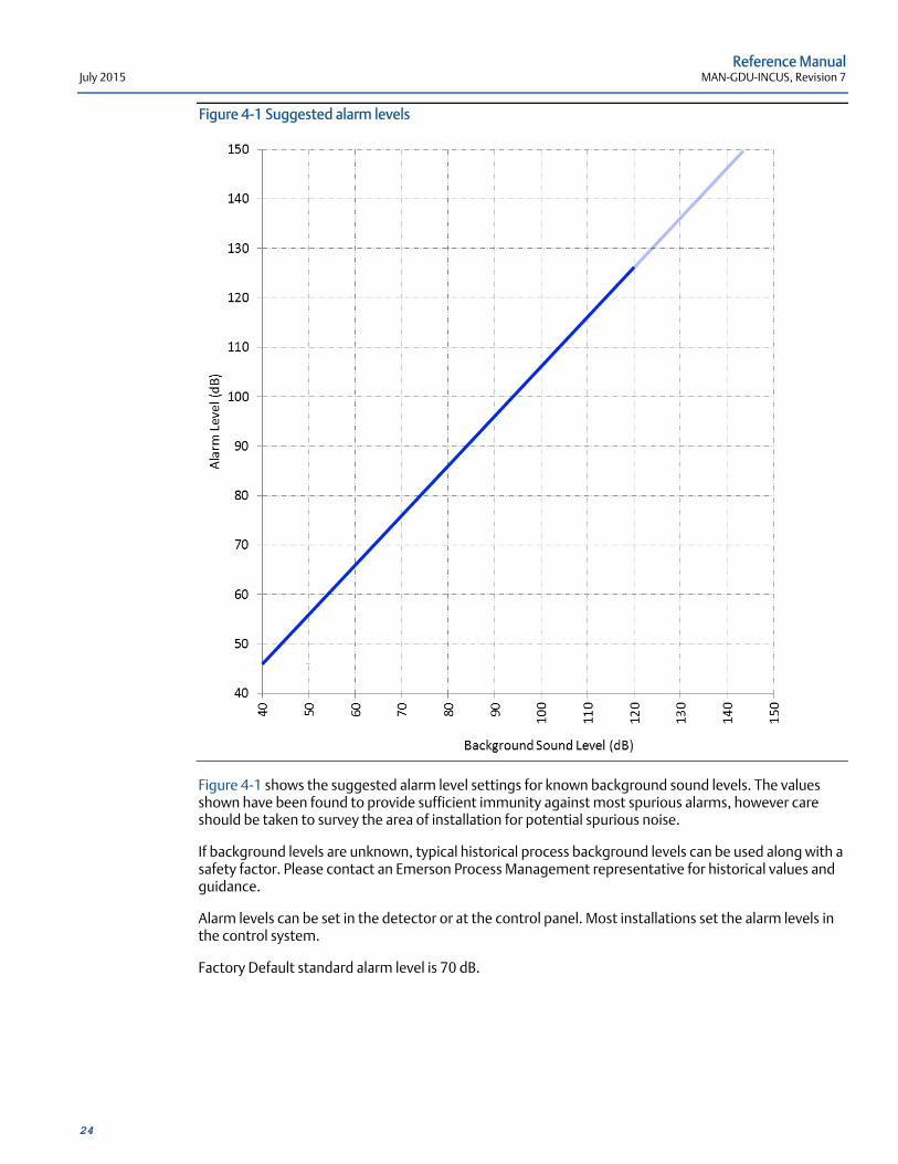
Figure 4-1 Suggested alarm levels
Figure 4-1 shows the suggested alarm level settings for known background sound levels. The values shown have been found to provide sufficient immunity against most spurious alarms, however care should be taken to survey the area of installation for potential spurious noise.
If background levels are unknown, typical historical process background levels can be used along with a safety factor. Please contact an Emerson Process Management representative for historical values and guidance.
Alarm levels can be set in the detector or at the control panel. Most installations set the alarm levels in the control system.
Factory Default standard alarm level is 70 dB.
Reference Manual MAN-GDU-INCUS, Revision 7 July 2015
25
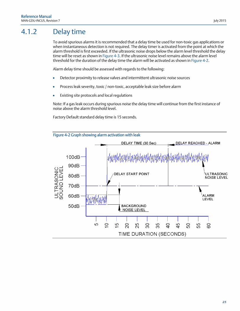
4.1.2 Delay time To avoid spurious alarms it is recommended that a delay time be used for non-toxic gas applications or when instantaneous detection is not required. The delay timer is activated from the point at which the alarm threshold is first exceeded. If the ultrasonic noise drops below the alarm level threshold the delay time will be reset as shown in Figure 4-3. If the ultrasonic noise level remains above the alarm level threshold for the duration of the delay time the alarm will be activated as shown in Figure 4-2.
Alarm delay time should be assessed with regards to the following:
Detector proximity to release valves and intermittent ultrasonic noise sources
Process leak severity, toxic / non-toxic, acceptable leak size before alarm
Existing site protocols and local regulations
Note: If a gas leak occurs during spurious noise the delay time will continue from the first instance of noise above the alarm threshold level.
Factory Default standard delay time is 15 seconds.
Figure 4-2 Graph showing alarm activation with leak

Reference Manual July 2015 MAN-GDU-INCUS, Revision 7
26
Figure 4-3 Graph showing no alarm activation with spurious noise
In Figure 4-3 noise 1 and 2 are spurious noise spikes of approx. 1.5 seconds, typical of man-made ultrasonic noise produced through normal maintenance procedures. Noise 3 is a longer spurious noise of approx. 13 seconds typical of a pressure relief valve. Delay time is introduced to ignore spurious noise spikes as the detector will reset when noise level drops below the alarm level before the delay time is reached.
Figure 4-4 Graph showing alarm activation with spurious noise and leak
Reference Manual MAN-GDU-INCUS, Revision 7 July 2015
27
Figure 4-4 shows detector response when a leak is encountered during a spurious noise spike such as a pressure relief valve. Noise 1 represents a pressure relief valve actuating for approximately 13 seconds before a leak (noise 2) occurs. The detector starts the delay time when the pressure relief valve opens and continues to monitor for leaks. If a leak occurs during a spurious noise spike the delay time will be reduced by the duration of the spurious noise spike.
It is important that all spurious noise spikes of significant duration within the detector coverage are identified. It is recommended that the alarm delay is set to a value greater than the maximum spurious noise spike operating duration. If two or more spurious noise sources are situated within the detector coverage area, it is recommended to assess whether activation of these sources can overlap in time, in which case the delay time should be extended accordingly.
4.1.3 Automatic self-test The automatic self-test checks the complete detector every 320 ms by sending an electrical signal of known amplitude through the sensing circuitry and analyzing the result, without interrupting the normal functionality of the sensor. If drift, component failure or damage occurs a fault is signaled, refer to section 4.6.
4.2 Sensor functionality check The sensors on the GDU-Incus are factory calibrated and do not require adjustment. Before operation functionality checks are recommended to ensure correct installation. On power-up, the GDU-Incus will perform a diagnostic check to ensure all main functions are operational, and continuously monitors the sensors via the built in self-test.
Sensor functionality can be checked in two ways;
GDU-Incus handheld series test transmitter sound source. Ensure that the background ultrasonic level is suitable for the distance of proposed test transmitter test. Aim the transmitter at the sensor face from a known distance, The GDU-Incus display dB level will rise according to the hand held device used and distance. Check all four (4) sensors, if possible, by moving around the detector and repeating.
Test verification kit — a pressurised gas release of a known pressure and size at a known distance. The GDU-Incus display level will rise according to the size, pressure, and distance used.
4.3 Output options The GDU-Incus comes with most industry standard forms of communication as standard. This enables the detector to be operated as part of a system, a standalone unit, or hard wire linked to form a sub network.
Reference Manual July 2015 MAN-GDU-INCUS, Revision 7
28
4.3.1 Relay Options The GDU-Incus has two relays configured as follows for the standard factory default;
Relay Type Factory Default Setting
1 Fault Energized in normal operating condition, de-energized in fault condition, non-latching.
2 Alarm Energized in normal operating condition, de-energized in alarm condition, non-latching.
Relay Data
Maximum switching current 1.4 A
Maximum switching voltage 30 VDC
Relay configuration can be changed to suit installation requirements using the user changeable functions, options include Normally Open / Normally Closed condition and latching / non-latching.
Refer to GDU-INCUS RS485 Specification document (MAN-GDU-INCUS-RS485) for more information on setup of the relays.
4.4 Display The GDU-Incus incorporates a 5 digit x 7 segment, 8 mm high x 4 mm wide character LED display with red numerals as standard.
During operation the real-time dB level is continuously shown while below the programmed alarm level and flashing when above the programmed alarm level.
Figure 4-5 Example of real-time dB level display ‘53dB’
If a maintenance/minor fault occurs the display will continue to display the real-time dB value, but will also show a flashing red dot on digit 1 to indicate that a fault has occurred.
If a major fault occurs, the display will shut down.
Display delay (pulse filter) can be set to delay the results shown on the LED to eliminate spiked spurious noise events and display a more consistent value.
Display settings can be changed using the user changeable functions; Refer to GDU-INCUS RS485 Specification document (MAN-GDU-INCUS-RS485).
Reference Manual MAN-GDU-INCUS, Revision 7 July 2015
29
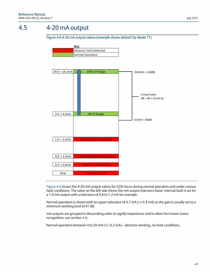
4.5 4-20 mA output Figure 4-6 4-20 mA output values (example shows default Op-Mode 71)
Figure 4-6 shows the 4-20 mA output values for GDU-Incus during normal operation and under various fault conditions. The value on the left side shows the mA output tolerance band, internal fault is set for a 1.0 mA output with a tolerance of 0.8 to 1.2 mA for example.
Normal operation is shown with an upper tolerance of 4.7 mA (+/-0.3 mA) as the gain is usually set to a minimum working level of 47 dB.
mA outputs are grouped in descending order to signify importance and to allow for instant status recognition, see section 4.6;
Normal operation between 4 to 20 mA (+/- 0.2 mA) — detector working, no fault conditions.
Reference Manual July 2015 MAN-GDU-INCUS, Revision 7
30
4.6 Fault outputs
4.6.1 2.0 mA Sensor test fault One or more sensor heads fail to respond with a correct value during the automatic self-test. Output is continuous at 2.0 mA unless the test is subsequently passed successfully or an alarm condition occurs, in which case the normal sound level is transmitted on the current loop.
4.6.2 1.0 mA Internal process fault Continuous 1.0 mA (+/-0.2 mA) output for any known internal or external faults which include over-voltage, high/low external voltage, blown fuse, or high/low internal voltage.
4.6.3 0.5 mA ‘All Sensors dead’ fault Continuous 0.5 mA (+/-0.2 mA) output indicating that all 4 sensors have failed self-test. Firmware version 3.4 onwards. The GDU-Incus should be returned to Emerson Process Management for repair.
4.6.4 0 mA Major fault 0 mA output is either caused by a total loss of power to the detector, or a serious microprocessor fault. If a fault occurs due to loss of power, the fault will be cleared when power is reapplied to the detector. If a serious microprocessor fault occurs, the GDU-Incus should be returned to Emerson Process Management for repair.
4.7 RS485 digital interface The GDU-Incus incorporates an RS485 digital interface which allows access to sensor status and setting information. The RS485 interface allows the device to communicate in a simple point to point configuration or as part of a larger, multi-drop network. (The majority of the supported commands are duplicated on the alternative Infra-Red ‘remote-access’ interface).
The RS485 interface uses a Baud rate of 2400 and ideally should be wired via shielded ‘twisted pair’ cable to reduce interference, especially for cable runs longer than a few meters.
Full technical details of the packet structure and list of supported commands used in the RS485 communications interface are provided in the GDU-INCUS RS485 Specification document (MAN-GDU-INCUS-RS485) which is available on request.

Reference Manual MAN-GDU-INCUS, Revision 7 July 2015
31
Section 5: HART functionality The GDU-Incus has HART communication enabled by default. The HART communication mode is standard current output FSK, to HART protocol revision number 7. The Device reports the Primary Variable (PV) measurement of Sound Pressure Level in units of dB. The Secondary Variable (SV) reports the internal case temperature (degrees Celsius) of the GDU-Incus. The Tertiary variable (TV) reports the temperature of the heated section of the Incus, if the Heater option is fitted, otherwise will report the same data as the Secondary Variable.
A Device description (DD) file for Emerson AMS and 375/475 field terminals is available from Emerson Process Management. In addition, the unit can be used with FDT frame applications using a generic DTM.
Full technical details of the HART Interface are provided in the GDU-INCUS HART Field Device Specification document (MAN-GDU-INCUS-HART) which is available on request.
Notes:
1) The GDU-Incus does not support the Delayed-Response Mechanism, Burst-Mode or Write Protection.
2) The HART device parameters ‘Tag’ and ‘Long Tag’ are set to ‘INCUS’ and ‘GDU-02-INCUS’ by default. They should be set-up on site, to allow unique identification, if required.

Reference Manual July 2015 MAN-GDU-INCUS, Revision 7
32
Section 6: Maintenance 6.1 Handheld test
The GDU-01-TT test transmitter can be used to emit an ultrasonic tone of 40 kHz with a sound pressure level of approximately 106 dB at 1 m (3 ft). Using the GDU-01-TT handheld device makes testing the GDU-Incus and other types of ultrasonic detectors quick and cost effective as it may be undertaken at floor level at distances of up to 8 m (26 ft) (dependent on background noise) provided line of sight with the sensor can be achieved. It is recommended that all alarms are disabled and the 4-20 mA output is monitored from the control room or observed on the display. Testing is carried out to ensure that the sensors are functioning correctly in addition to any internal test function contained within the GDU-Incus. It is recommended that a handheld test is undertaken in line with existing site maintenance procedures.
Note: ensure that any internal test functions are disabled or not activated when undertaking a handheld test to avoid spurious results.
6.2 Verification test The GDU-PTV-01 performance target verification kit can be used to simulate an actual gas release to test both functionality and performance of ultrasonic gas detectors by generating a ‘burst release’ representative of that expected in the event of a gas leak. The GDU-PTV-01 should be used at the perimeter of the detector coverage to ensure that all leaks will be detected. It is recommended that all alarms are disabled and the 4-20 mA output is monitored from the control room or observed on the display. Testing is carried out to ensure that the sensors are functioning correctly in addition to any internal test function contained within the GDU-Incus with respect to sensor response and coverage. It is recommended that a verification test is undertaken at installation and in line with existing site maintenance procedures.
6.3 Troubleshooting The GDU-Incus cannot be repaired in the field. If a problem should develop, carefully check for faulty wiring. If it is determined that the problem is caused by an electronic defect, the device must be returned to the factory for repair (refer to 1.2 and 1.3 for instructions).
6.4 Storage The detector should be stored in locations free from dust and moisture. The storage temperature should be well within the limits of the certified temperatures of the equipment. See Section 7 for storage temperatures.
Reference Manual MAN-GDU-INCUS, Revision 7 July 2015
33
6.5 Spare parts and accessories
6.5.1 Spare parts
Enclosure Fastener Kits. Terminal cover fastener kit. Consists of 6 terminal cover fasteners and retaining washers.
Terminal Cover O Ring Upper Replacement terminal cover O ring for upper position, standard.
Terminal Cover O Ring Lower Replacement terminal cover O ring for lower position, standard.
Please refer to individual spare part installation sheets for further information.
Description Part number
Terminal Fastener Kit. Replacement Terminal Cover fasteners and retaining washers
GDU-02-TCFK
Terminal Cover O Ring Upper GDU-02-TCU
Terminal Cover O Ring Lower GDU-02-TCL
Reference Manual July 2015 MAN-GDU-INCUS, Revision 7
34
6.5.2 Accessories U-Bolt Kit Consists of two U-bolts and all fasteners required to allow the
GDU-Incus to be pole mounted using the standard mounting bracket. Size of U-bolt should be specified at time of order.
Test Transmitter Consists of a handheld, rechargeable ultrasonic sound emitter with carrying case, charger, and shoulder strap to allow remote independent testing of any ultrasonic gas leak detector from floor level. Note: the test transmitter is not hazardous area approved and will require a hot work permit.
PTV Kit Consists of 2 x 10 litre Nitrogen Gas cylinders (150 BAR) and a high pressure gas regulator which are attached to a trolley for portability.
Please refer to individual accessory datasheets for further information or contact an Emerson Process Management representative.
Description Part Number
Test Transmitter. Handheld rechargeable Ultrasonic Sound Emitter GDU-01-TT
Performance Target Verification (PTV) Kit GDU-PTV-01
Reference Manual MAN-GDU-INCUS, Revision 7 July 2015
35
Section 7: Specifications 7.1 General
7.1.1 Detection method Floating Piezo Ceramic — non consumable, non-ageing
7.1.2 Gases detected All pressurized gases, minimum leak pressure 2 bar (Gauge), leak size dependent
7.1.3 Self-test Continuous electronic check of sensor integrity
7.1.4 Calibration Factory set
7.2 Output signal
7.2.1 4 — 20 mA Current source 4 — 20 mA, corresponds to 40 to 120 dB SPL — Maximum load resistance 500 Ω standard.
Current sink 4-20 mA (option)
7.2.2 Digital RS485 interface
7.2.3 Relay 1 Error / Fault (NO or NC option)
Load: 1.4 A max. Switch Voltage 30 Vdc max. Contact resistance 70 mΩ
7.2.4 Relay 2 Alarm (NO or NC option)
7.2.5 HART® Supplied as standard.
Reference Manual July 2015 MAN-GDU-INCUS, Revision 7
36
7.3 Performance
7.3.1 Detection frequency range 25 kHz to 100 kHz
7.3.2 Dynamic range 40 dB to 120 dB SPL (In standard operating mode)
7.3.3 Response time Instantaneous (Less than 1 second with HART® outputs; alarm delay via 1 second variable increments — customer programmable)
7.3.4 Detection coverage 2 to 20 meters (7 to 65 foot) radius (leak pressure, size and background level dependent). Greater distances may be achieved subject to application consultation.
7.3.5 Start-up time Less than 5 seconds
7.4 Electrical
7.4.1 Operating voltage range 15 to 30 Vdc
7.4.2 Power consumption Standard Unit: 250 mA (at maximum display brightness) during normal operation
Heated Unit: 1.5 A at maximum display brightness and with heaters drawing maximum current (at -55°C)
7.4.3 Cable entry ATEX/IECEx/INMETRO/EAC/KOSHA: Dual M20 cable entries.
FM (US & Canada): Single ¾” NPT conduit entry
Reference Manual MAN-GDU-INCUS, Revision 7 July 2015
37
7.5 Environmental
7.5.1 Storage temperature -55°C to +85°C (-67°F to +185°F)
7.5.2 Operating temperature Standard Unit: -40°C to +85°C (-40°F to +185°F)
Heated Unit: -55°C to +85°C (-67°F to +185°F)
7.5.3 Relative humidity Humidity (operating): 0 to 100% relative humidity
7.5.4 Metallurgy Stainless steel (AISI 316)
7.5.5 Ingress protection IP66/IP67 Type 4X
7.5.6 Weight Approx. 18 kg (39.8 lb.)
7.5.7 Dimensions (without bracket) Ø210 x 272 mm (Ø8 ¼“ x 10 ¾“)
7.6 Warranty 18 months after shipment or 12 months after installation, whichever comes first
Reference Manual July 2015 MAN-GDU-INCUS, Revision 7
38
Section 8: Certifications 8.1 Marking
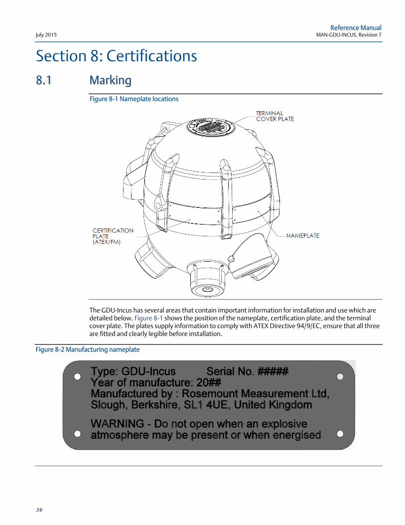
Figure 8-1 Nameplate locations
The GDU-Incus has several areas that contain important information for installation and use which are detailed below. Figure 8-1 shows the position of the nameplate, certification plate, and the terminal cover plate. The plates supply information to comply with ATEX Directive 94/9/EC, ensure that all three are fitted and clearly legible before installation.
Figure 8-2 Manufacturing nameplate
Reference Manual MAN-GDU-INCUS, Revision 7 July 2015
39
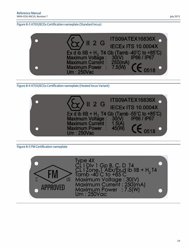
Figure 8-3 ATEX/IECEx Certification nameplate (Standard Incus)
Figure 8-4 ATEX/IECEx Certification nameplate (Heated Incus Variant)
Figure 8-5 FM Certification nameplate
Reference Manual July 2015 MAN-GDU-INCUS, Revision 7
40
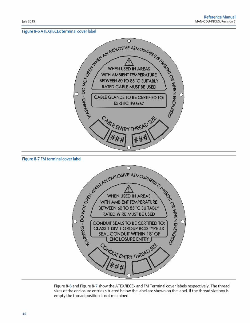
Figure 8-6 ATEX/IECEx terminal cover label
Figure 8-7 FM terminal cover label
Figure 8-6 and Figure 8-7 show the ATEX/IECEx and FM Terminal cover labels respectively. The thread sizes of the enclosure entries situated below the label are shown on the label. If the thread size box is empty the thread position is not machined.
Reference Manual MAN-GDU-INCUS, Revision 7 July 2015
41
8.2 ATEX II 2 G Ex d ib IIB+H2 T4 Gb IP66/IP67
-55°C/-40°C ≤ Ta ≤ +85°C ITS09ATEX16836X
8.3 IECEx II 2 G Ex d ib IIB+H2 Gb T4 IP66/IP67 -55°C/-40°C ≤ Ta ≤ +85°C ITS 10.0004X
8.4 FM (US & Canada) Class I, Div.1 Groups B, C, and D T4 Class I, Zone 1 AEx/Ex d ib IIB+H2 T4 -40°C ≤ Ta ≤ +85°C, Type 4X 3043275
8.5 EAC 1Ex d ib IIB+H2 T4 Gb X -55°C/-40°C ≤ Ta ≤ +85°C RU C-GB.ГБ04.B.00297
8.6 INMETRO Ex d ib IIB+H2 T4 Gb -55°C/-40°C ≤ Ta ≤ +85°C UL-BR 15.0063X
8.7 KCs Ex d ib IIB+H2 T4 -55°C/-40°C ≤ Ta ≤ +85°C 14-KB4BO-0294X
Reference Manual July 2015 MAN-GDU-INCUS, Revision 7
42
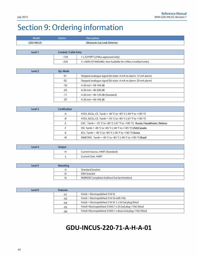
Section 9: Ordering information Model Option Description
GDU-INCUS Ultrasonic Gas Leak Detector
Level 1 Conduit / Cable Entry
-134 1 x 3/4"NPT (cFMus approved only)
-220 2 x M20 (STANDARD, Not Available for cFMus Certified Units)
Level 2 Op. Mode
01 Stepped analogue signal (bi-state: 4 mA no alarm; 12 mA alarm)
02 Stepped analogue signal (bi-state: 4 mA no alarm; 20 mA alarm)
-50 4-20 mA = 58-104 dB
-65 4-20 mA = 40-200 dB
-71 4-20 mA = 40-120 dB (Standard)
-97 4-20 mA = 40-104 dB
Level 3 Certification
-A ATEX, IECEx, CE. Tamb = -40 °C to +85 °C (-40 °F to +185 °F)
-B ATEX, IECEx, CE. Tamb = -55 °C to +85 °C (-67 °F to +185 °F)
-E EAC. Tamb = -55 °C to +85 °C (-67 °F to +185 °F). Russia / Kazakhstan / Belarus
-F FM. Tamb = -40 °C to +85 °C (-40 °F to +185 °F) USA/Canada
-K KCs. Tamb = -40 °C to +85 °C (-40 °F to +185 °F) Korea
-M INMETRO. Tamb = -40 °C to +85 °C (-40 °F to +185 °F) Brazil
Level 4 Output
-H Current Source, HART (Standard)
-J Current Sink, HART
Level 5 Mounting
-A Standard bracket
-D DNV bracket
-N NORSOK Compliant (Indirect Exe termination)
Level 6 Features
-01 Finish = Electropolished 316 SS
-02 Finish = Electropolished 316 SS with TAG
-04 Finish = Electropolished 316 SS 1 x SS Exd plug fitted
-05 Finish=Electropolished 316SS 1 x SS Exd plug +TAG fitted
-06 Finish=Electropolished 316SS 1 x Brass Exd plug +TAG fitted
GDU‐INCUS‐220‐71‐A‐H‐A‐01

MAN-GDU-INCUS Revision 7 July 2015
Emerson Process Management Rosemount Measurement Ltd. 158 Edinburgh Avenue, Slough, Berkshire, SL1 4UE, UK Tel +44 (0)1753 756600 Fax +44 (0)1753 823589 Rosemount Measurement Limited, registered in England and Wales No. 293743, VAT#864383106 Registered Office: 2nd Floor Accurist House, 44 Baker Street, London W1U 7AL
©2015 Emerson Process Management. All rights reserved.
Emerson Process Management, Rosemount Analytical, Net Safety Monitoring, and Groveley Detection Limited are marks of Emerson Process Management group of companies. All other marks are the property of their respective owners.
The contents of this publication are presented for information purposes only, and while effort has been made to ensure their accuracy, they are not to be construed as warranties or guarantees, express or implied, regarding the products or services described herein or their use or applicability. All sales are governed by our terms and conditions, which are available on request. We reserve the right to modify or improve the designs or specifications of our products at any time without notice.

Reference Manual MAN-GDU-INCUS, Revision 7 July 2015