Embed Size (px)
Citation preview
Cement and Concrete Research 39 (2009) 1068–1076
Contents lists available at ScienceDirect
Cement and Concrete Research
j ourna l homepage: ht tp: / /ees.e lsev ie r.com/CEMCON/defau l t .asp
Reinforcement corrosion initiation and activation times in concrete structuresexposed to severe marine environments
R.E. Melchers a,⁎, C.Q. Li b
a Centre for Infrastructure Performance and Reliability, School of Engineering, The University of Newcastle, Australiab Department of Civil Engineering, The University of Greenwich, England
⁎ Corresponding author.E-mail address: [email protected] (R.E
0008-8846/$ – see front matter © 2009 Elsevier Ltd. Adoi:10.1016/j.cemconres.2009.07.003
a b s t r a c t
a r t i c l e i n f oArticle history:Received 27 March 2008Accepted 3 July 2009
Keywords:CorrosionLong-term performanceChlorideReinforcement
The corrosion of steel reinforcement bars in reinforced concrete structures exposed to severe marineenvironments usually is attributed to the aggressive nature of chloride ions. In some cases in practicecorrosion has been observed to commence already within a few years of exposure even with considerableconcrete cover to the reinforcement and apparently high quality concretes. However, there are a number ofother cases in practice for which corrosion initiation took much longer, even in cases with quite modestconcrete cover and modest concrete quality. Many of these structures show satisfactory long-term structuralperformance, despite having high levels of localized chloride concentrations at the reinforcement. Thisdisparity was noted already more than 50 years ago, but appears still not fully explained. This paper presentsa systematic overview of cases reported in the engineering and corrosion literature and considers possiblereasons for these differences. Consistent with observations by others, the data show that concretes madefrom blast furnace cements have better corrosion durability properties. The data also strongly suggest thatconcretes made with limestone or non-reactive dolomite aggregates or sufficiently high levels of other formsof calcium carbonates have favourable reinforcement corrosion properties. Both corrosion initiation and theonset of significant damage are delayed. Some possible reasons for this are explored briefly.
© 2009 Elsevier Ltd. All rights reserved.
1. Introduction
The early occurrence and high rate of corrosion of reinforcement inconcrete structures exposed to marine environments or to repeatedapplications of de-icing salts is a problem that has been of interest formany decades [1–3]. That the problem is still not resolved is evident inthe search for remediation measures, in the uncertainty in the criteriaand guidelines for the durability design of reinforced concretestructures and in the continued exploration of alternative measuresand materials [4]. However, specialist treatments and new materialsmay not be the key to the problem since already some 50 years agoWakeman et al. [2] posed the question ‘Why do some concretestructures seem to last indefinitely in seawater while othersdeteriorate within a comparatively short time?’ Similarly, some30 years later, Burkowsky and Englot [5] note that for New York andNew Jersey road bridges a wide variation in durability performancewas observed, even for major bridges that are essentially similar indesign and construction. While some have required extensive main-tenance, others are ‘… standing up well — even after 60 years ofservice. Why the difference?’
. Melchers).
ll rights reserved.
Wakeman et al. [2] proposed some answers that have been echoedmany times since, based both on experience and on research. Theyadvocated ‘dense, impervious, relatively nonabsorbent concrete’, aminimum concrete cover of 3 in. (75 mm), sufficiently high cementcontent, a low water/cement ratio, non-reactive aggregates and goodcompaction and curing. These are consistent with what currently isstill considered good practice. These desiderata are based on theaccepted notion that in marine environments chloride ions areaggressive to the passive layer assumed to exist on the exterior ofsteel reinforcement and that breakdown of this layer causes localizedcorrosion [6–8]. However, there are structures in practice exposed toextremely aggressive marine environments for which one or more ofthe desiderata have been violated, yet the structures have lasted manyyears with little or no signs of corrosion. For example, Burkowsky andEnglot [5] commenting on the effectiveness of conventional predictivetools, such as polarization resistance and pH measurements andchloride concentrations noted that typically ‘…test results for thegood decks (that) could not be separated easily from those for theproblem decks…’ and ‘…so-called “indicator tests” were contradictedby… actual deck performance.’ They found that very high chloridecontents, in excess of 1 lb per cu. yd of concrete (approx 0.2% bycement), were commonwithout a corresponding history of reinforce-ment corrosion. Similarly, Borgard et al. [9] note the occurrence ofhigh levels of chloride adjacent to reinforcement that has not corroded
1069R.E. Melchers, C.Q. Li / Cement and Concrete Research 39 (2009) 1068–1076
and reinforcing steel ‘removed from concrete after many years with noindication that it has ever been exposed to a wet environment’.
One of the difficulties with these various comparisons is thatusually different structures of different complexities at different loca-tions with different micro-climates and built to differing design andconstruction standards are being compared. Moreover, there usuallyare also differences in detail design and considerable variability inconstruction and workmanship practices. Usually these factors takentogether make comparison of the performance of reinforced concretestructures problematic. However, this is not always the case.
Recently, Melchers and Li [10] reported the very considerabledifference in durability performance of some 1000 very simple andalmost identical reinforced concrete elements all exposed to the sameaggressivemarine environment of the North Sea at Arbroath, Scotland.This means that differences due to location and micro-climate and instructural form and hence exposure are negligible and that onlydifferences in materials are of interest. It is therefore noteworthy thatover 90% of the elements constructed in 1943 had survived to 2006with almost no evidence of corrosion initiation despite their beingof apparent lower quality concrete than subsequent elements. Thesewere constructed in 1968 and 1993 and show severe reinforcementcorrosion and longitudinal cracking of the elements. Tests showedthat concrete permeability for the three concretes was generallysimilar and chloride concentrations at the reinforcement was as highfor the 1943 elements as for the 1993 elements but much higher thanthat for the badly corroded 1968 elements. While only limited pHreadings could be taken on the few cross-sections available to theinvestigators, they did not suggest much difference in concretealkalinity between the three concretes even though the concretesare of very different ages. Detailed examination showed that unlikethe subsequent elements, the 1943 elements were all constructedwith seashells in the concrete mix. Seashells are predominantly ara-gonite, one of the polymorphs of calcium carbonate. Because con-struction records are no longer available, it is uncertain whether theseashells were rinsed with fresh water prior to use and whetherseawater was used in the 1943 concrete.
The aim of the present paper is to investigate whether there areother cases reported in the literature for which there is correlationbetween reinforcement durability, elevated levels of calcium carbo-nate in the concrete matrix and concentration of chlorides at the levelof the reinforcement. Of particular interest are observations and datafor actual reinforced concrete structures under marine exposure con-ditions or subject to de-icing salts. Unfortunately, and for obviousreasons, there are almost no systematic observations directly of rein-forcement bars in actual structures and how that reinforcement cor-rodes as a function of exposure time for realistic exposure conditions.Mostly what is available are data for observations of the externalsurfaces of concrete structures. Such observations are used herein,using data extracted from the open literature, both for in-situ ob-servations and for some laboratory tests.
2. Background
Corrosion of reinforcement usually is considered to initiate whenchlorides from the external environment have penetrated sufficientlyfar into the concrete matrix to reach the reinforcement in concentra-tions high enough to break down the passive layer on surface of thereinforcement [6]. Such chlorides can arise from seawater or salt-spray particles. Chlorides also may originate from de-icing salts wherethese are used on road bridges.
One role for the concrete surrounding the reinforcement is toprovide physical protection against the migration of aggressive chlo-ride ions. The other role of the concrete is that it provides an alkalineenvironment around the bars. The alkalinity of the concrete soon aftercasting typically is high and this develops a passive layer on thesurface of the reinforcement. For mild and low alloy reinforcing steels
this usually inhibits the initiation of the corrosion process. The highalkalinity is the result of the presence of highly alkaline calcium,sodium and potassium hydroxide ions. It has been observed, however,that the hydroxide ions can leach out of the concrete slowly with time[11–14]. Perhaps in combination with concrete carbonation, this willcontribute to the gradual lowering of the alkalinity surrounding thereinforcement bars and the observed lower pH value of olderconcretes. Eventually this leads to the initiation of corrosion of thereinforcement.
There are numerous observations that corrosion initiates at voids,air pockets or pores in the concrete immediately adjacent to thereinforcement, that is, at locations where there is no immediatepresence of alkalies [15,16] and there is a small local pocket or limitedsupply of oxygen. As a result, initial corrosion typically occurs aslocalized corrosion (sometimes called pitting corrosion).
While the process of corrosion initiation is controlled by the pH ofthe concrete and hence by the availability of a sufficiently high levelof hydroxides, influenced in marine conditions by the presence ofaggressive chloride ions, the process of subsequent continued cor-rosion is through oxidation of the reinforcement. As for bare steel inthe atmosphere and under immersion conditions, the rate of oxidationis controlled primarily by the rate of supply of oxygen to the rein-forcement impeded by the concrete cover [17,18].
It is conventional in many practical applications to use a simplifiedmodel to represent the changing pattern of corrosion loss with time.The most common approach does not deal directly with the corrosionof the reinforcing steel at all, but with its consequences, such ascracking, spalling and rust staining of the concrete, measured throughthe index ‘damage’ [19,20] even though this is obviously a parameterthat can be defined only imprecisely. The usual assumption is that zerodamage (and by implication insignificant corrosion) occurs prior tothe reaching of some threshold time tt sometimes known as the‘corrosion initiation time’ (Fig.1a). Since the relationship in Fig.1a is interms of damage, a more correct interpretation of tt in this context isthat it indicates the commencement of damage and in turn that thismeans the commencement of significant corrosion. In this modeldamage usually is assumed to increases linearly with time after tt. Thismodel is the well-known bi-linear ‘damage’ model. It has a con-siderable history and is widely advocated [8,21].
In applications of the bi-linear damage model it is customary (andconservative) to assume that the cessation of adequate structuralperformance occurs at the onset of significant damage, that is, at timett (Fig. 1a). This threshold of unacceptable damage is linked to athreshold chloride level, or, in other treatments, to a threshold ratio ofthe concentrations of chlorides to hydroxides at the reinforcement.The implication is that low levels of chlorides would not initiatecorrosion. However, there have been many reports of reinforcementcorrosion having initiated much earlier, as evident by rust stains andminor surface cracking sometimes with rust stains but with little or noevidence of further corrosion until much later (e.g. [24]). For thisreason it is appropriate to add an earlier threshold, that of corrosioninitiation, at time ti and to distinguish this from active corrosion thatoccurs at a subsequent time tac (Fig. 1b) [22, 23].
Because of the importance conventionally attached to chlorides inthe corrosion of reinforcement there has been much researchattempting to define the threshold limit below which the action ofchloride ions is considered to be of little importance [6,8]. Attentionhas been given also to the role of bound chlorides and much lessattention to the leaching of hydroxide ions. Most research effort hasbeen devoted to understanding the transportation of chlorides fromthe external environment into the concrete towards the reinforce-ment, often simplified by assuming Fickian (i.e. so-called ‘linear’)diffusion controls the process, whereas the reality is more complex.This has led to adaptations of the simple theory to meet fieldobservations, with the diffusivity described by an equivalent systemwith an ‘apparent’ diffusivity coefficient [7]. Despite these extensive
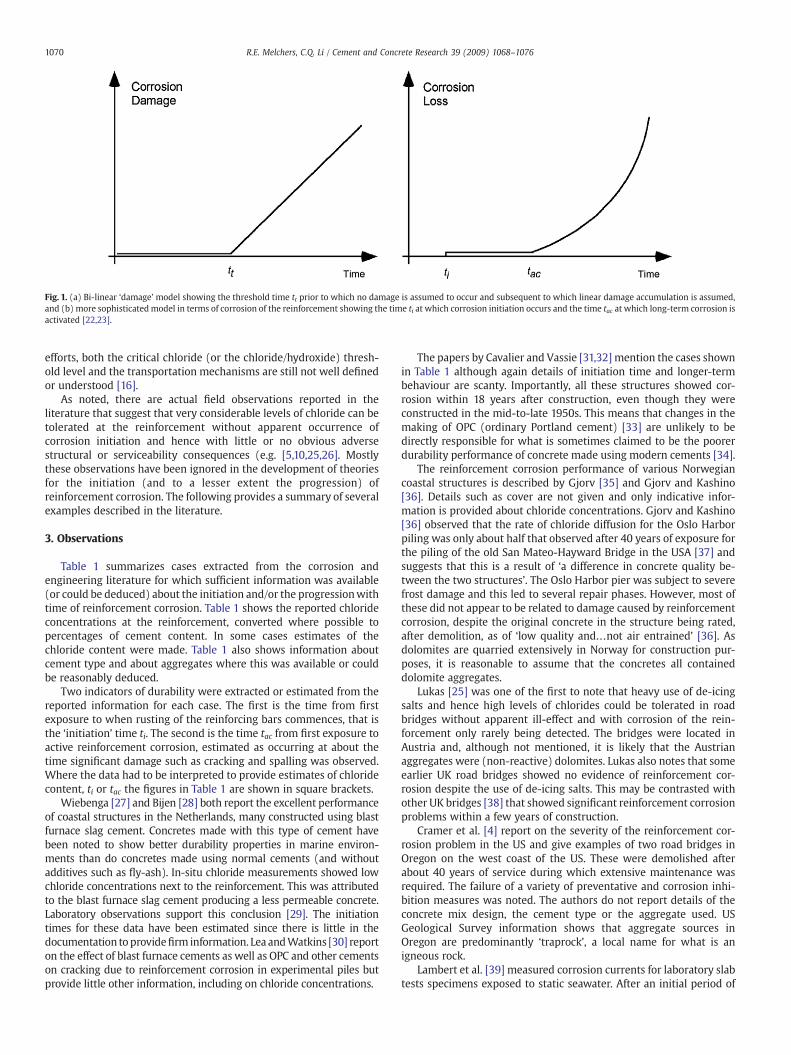
Fig. 1. (a) Bi-linear ‘damage’ model showing the threshold time tt prior to which no damage is assumed to occur and subsequent to which linear damage accumulation is assumed,and (b) more sophisticatedmodel in terms of corrosion of the reinforcement showing the time ti at which corrosion initiation occurs and the time tac at which long-term corrosion isactivated [22,23].
1070 R.E. Melchers, C.Q. Li / Cement and Concrete Research 39 (2009) 1068–1076
efforts, both the critical chloride (or the chloride/hydroxide) thresh-old level and the transportation mechanisms are still not well definedor understood [16].
As noted, there are actual field observations reported in theliterature that suggest that very considerable levels of chloride can betolerated at the reinforcement without apparent occurrence ofcorrosion initiation and hence with little or no obvious adversestructural or serviceability consequences (e.g. [5,10,25,26]. Mostlythese observations have been ignored in the development of theoriesfor the initiation (and to a lesser extent the progression) ofreinforcement corrosion. The following provides a summary of severalexamples described in the literature.
3. Observations
Table 1 summarizes cases extracted from the corrosion andengineering literature for which sufficient information was available(or could be deduced) about the initiation and/or the progressionwithtime of reinforcement corrosion. Table 1 shows the reported chlorideconcentrations at the reinforcement, converted where possible topercentages of cement content. In some cases estimates of thechloride content were made. Table 1 also shows information aboutcement type and about aggregates where this was available or couldbe reasonably deduced.
Two indicators of durability were extracted or estimated from thereported information for each case. The first is the time from firstexposure to when rusting of the reinforcing bars commences, that isthe ‘initiation’ time ti. The second is the time tac from first exposure toactive reinforcement corrosion, estimated as occurring at about thetime significant damage such as cracking and spalling was observed.Where the data had to be interpreted to provide estimates of chloridecontent, ti or tac the figures in Table 1 are shown in square brackets.
Wiebenga [27] and Bijen [28] both report the excellent performanceof coastal structures in the Netherlands, many constructed using blastfurnace slag cement. Concretes made with this type of cement havebeen noted to show better durability properties in marine environ-ments than do concretes made using normal cements (and withoutadditives such as fly-ash). In-situ chloride measurements showed lowchloride concentrations next to the reinforcement. This was attributedto the blast furnace slag cement producing a less permeable concrete.Laboratory observations support this conclusion [29]. The initiationtimes for these data have been estimated since there is little in thedocumentation toprovidefirm information. Lea andWatkins [30] reporton the effect of blast furnace cements as well as OPC and other cementson cracking due to reinforcement corrosion in experimental piles butprovide little other information, including on chloride concentrations.
The papers by Cavalier and Vassie [31,32] mention the cases shownin Table 1 although again details of initiation time and longer-termbehaviour are scanty. Importantly, all these structures showed cor-rosion within 18 years after construction, even though they wereconstructed in the mid-to-late 1950s. This means that changes in themaking of OPC (ordinary Portland cement) [33] are unlikely to bedirectly responsible for what is sometimes claimed to be the poorerdurability performance of concrete made using modern cements [34].
The reinforcement corrosion performance of various Norwegiancoastal structures is described by Gjorv [35] and Gjorv and Kashino[36]. Details such as cover are not given and only indicative infor-mation is provided about chloride concentrations. Gjorv and Kashino[36] observed that the rate of chloride diffusion for the Oslo Harborpiling was only about half that observed after 40 years of exposure forthe piling of the old San Mateo-Hayward Bridge in the USA [37] andsuggests that this is a result of ‘a difference in concrete quality be-tween the two structures’. The Oslo Harbor pier was subject to severefrost damage and this led to several repair phases. However, most ofthese did not appear to be related to damage caused by reinforcementcorrosion, despite the original concrete in the structure being rated,after demolition, as of ‘low quality and…not air entrained’ [36]. Asdolomites are quarried extensively in Norway for construction pur-poses, it is reasonable to assume that the concretes all containeddolomite aggregates.
Lukas [25] was one of the first to note that heavy use of de-icingsalts and hence high levels of chlorides could be tolerated in roadbridges without apparent ill-effect and with corrosion of the rein-forcement only rarely being detected. The bridges were located inAustria and, although not mentioned, it is likely that the Austrianaggregates were (non-reactive) dolomites. Lukas also notes that someearlier UK road bridges showed no evidence of reinforcement cor-rosion despite the use of de-icing salts. This may be contrasted withother UK bridges [38] that showed significant reinforcement corrosionproblems within a few years of construction.
Cramer et al. [4] report on the severity of the reinforcement cor-rosion problem in the US and give examples of two road bridges inOregon on the west coast of the US. These were demolished afterabout 40 years of service during which extensive maintenance wasrequired. The failure of a variety of preventative and corrosion inhi-bition measures was noted. The authors do not report details of theconcrete mix design, the cement type or the aggregate used. USGeological Survey information shows that aggregate sources inOregon are predominantly ‘traprock’, a local name for what is anigneous rock.
Lambert et al. [39] measured corrosion currents for laboratory slabtests specimens exposed to static seawater. After an initial period of
1071R.E. Melchers, C.Q. Li / Cement and Concrete Research 39 (2009) 1068–1076
about 2 weeks of active corrosion, the corrosion current dropped tovery low values and only later increased again. This is consistent withthe model of Fig. 1(b). The increase in corrosion current generallywas delayed for greater concrete cover and was found to depend onthe ratio of wet time to dry time. Both are as expected. However, theauthors did not comment on the result in the paper that showedspecimens with limestone aggregate having initiation times signifi-cantly longer than those for specimens with quartzite aggregate. Thesame cement (OPC) was used throughout.
The data reported by Polder and Hug [40] for the corrosion ofreinforcement of a footbridge requires some interpretation. Thegreatest deterioration occurred for a part of the bridge initiallyprotected with an epoxy coating but when this became permeableit also retained moisture inside the concrete, thereby artificially in-creasing the ‘time of wetness’ to much higher levels than for theadjacent parapets. However, these were subjected to much lowerlevels of application of de-icing salts. The frequency of de-icing saltapplication was considered to be modest given the relatively mildwinters in The Netherlands. The net result is that the time to activecorrosion is over-estimated for the parapets compared with that forthe epoxy-coated part of the bridge once the coating lost its protectivecover, estimated as between 10 and 15 years.
Castel et al. [41,42] found no correlation between longer-termcorrosion and chloride content for reinforced concrete beams exposedfor 17 years in the laboratory to a saline fog environment. Althoughthe chloride content was well above the usual thresholds there waslittle evidence of reinforcement corrosion. It was suggested thatcorrosion occurred only where there was a lack of intimate contactbetween the reinforcement and the surrounding concrete. Thisaccords with the recognized notion that air pockets at the interfacelayer are correlated with local corrosion [15].
For the Hathaway Bridge located in coastal southern Florida, Lauet al. [26] noted that even after 42 years in-service the 76 support pilesshowed little sign of corrosion initiation. Exposure of the reinforcingbars revealed only a dull to lustrous grey mill scale but no discernablerust. Similarly, for the Pensacola Bridge, there was only minor cor-rosion after 43 years exposure. Fewer than 2% of the 908 bridge pilesexamined showed rust stains greater than 100 cm2. Smaller rust stainswere noted on about 25% of the piles. The Brooks Bridge, only slightlyyounger at 39 years, showed only some superficial rust staining. Theinitiation times shown in Table 1 were estimated conservatively usingthe published information. In view of the predominant limestonegeology of southern Florida, it is likely that the aggregate noted as‘river rock’ is limestone or dolomite.
Sagues [43] also dealt with bridges in Florida. These ranged in agefrom 18 to about 30 years and were exposed to aggressive marineconditions. In general, polarization resistance measurements indi-cated negligible corrosion, consistent with visual observations of lowincidence of reinforcement corrosion and rust staining. This was thecase also for the Florida Keys bridges that were noted as havingsubstantial deviations from the nominal cover. It was not uncommonfor the cover to be ‘as little as 25 mm’ and ‘some instances of no coverwere encountered’. The first concrete spalls were noted after only 6–9 years in-service. Since these are likely to be associated with lowcover, they are not typical and the initiation time for areas of thebridges complying with design cover requirements is likely to besignificantly longer.
Pronounced differences in reinforcement durability for road bridgessubject to de-icing salts in New York and New Jersey led to detailed fieldand laboratory investigations of five selected bridges [5]. These werevery similar in many critical design aspects. Details relevant to thepresent paper are given in Table 1. Reference to US Geological Surveyreports shows that historically around 75–85% of crushed stone used forconstruction purposes in Pennsylvania State and New York State islimestone and dolomite. Overall aggregate production in the otherneighbouring states was much lower and was predominantly igneous
rock. Thus, although the source of aggregate used in each bridge cannotnow be established from the available published information, it is likelythat limestone or dolomite or both were used as concrete aggregate formost of the bridges.
Melchers and Li [10] observed that over 90% of simple pre-castreinforced concrete handrails constructed at Arbroath, Scotland, in1943 showed little or no sign of corrosion initiation even after morethan 63 years of exposure to the North Sea. Some handrails werereplaced in 1968 and others in 1993 for reasons that cannot now betraced, although it may be assumed that they showed signs of rein-forcement corrosion.When inspected in 2003 themajority of the 1968and 1993 replacements were found to be badly cracked longitudinallyas a result of significant reinforcement corrosion. The 1943 handrailsall contain seashells as part of the concrete mix. Both the 1968 and the1993 concretes contain only igneous aggregates. Visual inspectionof the interior and of exterior surfaces and concrete permeabilitymeasurements indicated that the later concretes were generally ofbetter quality than the 1943 concrete, consistent with the war-timeconstruction of the 1943 concrete and the obvious presence of sea-shells in the concrete, suggesting also the possible use of seawater forconcrete mixing water. While not conclusive, these indicators suggestthat if anything the 1943 concrete should have beenworse rather thanbetter than the later concretes.
4. Analysis
Table 1 shows estimates for ti and tac. Where possible informationreported in the literature is given, in other cases the Authors inter-preted the available information. This is shown with square brackets.
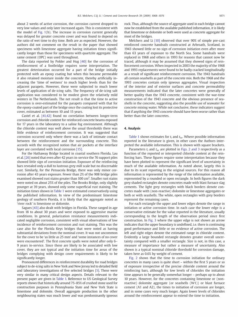
Parameters ti and tac are plotted in Figs. 2 and 3 respectively as afunction of the reported or interpreted chloride content at the rein-forcing bars. These figures require some interpretation because theyhave been plotted to represent the significant level of uncertainty inmuch of the available information. As noted above, largely this isdue to its scant reporting in the original sources. For this reason allinformation is represented by the range of the information available,represented by a rounded or open rectangle. In both figures the darkgrey shaded rectangles denote concretes made with blast furnace slagcements. The light grey rectangles with black borders denote con-cretes made with (non-reactive) dolomite or limestone aggregates orboth or with seashells. The white, open rectangles with grey bordersrepresent the remaining cases.
For each rectangle the upper and lower edges denote the range ininitiation or active corrosion time. In each case the lower edge is aconservative estimate for the value reported in the literature, usuallycorresponding to the length of the observation period since firstconstruction. In Fig. 3 where the upper edge is not shown an arrowindicates that the upper boundary is undefined, i.e. there is continuinggood performance and little or no evidence of active corrosion. Theleft and right edges denote the estimated range in chloride content.Evidently a large bounded rectangle denotes greater overall uncer-tainty compared with a smaller rectangle. Size is not, in this case, ameasure of importance but rather a measure of uncertainty. Alsoshown is a typical nominal chloride threshold for corrosion damage,taken here as 0.6% by weight of cement.
Fig. 2 shows that the time to corrosion initiation for ordinaryconcretes in many cases is quite short – within the first 5 years or soof exposure irrespective of the precise chloride content around thereinforcing bars, although for low levels of chlorides the initiationtime appears to be generally somewhat longer – perhaps up to about10 years. However, for the concretes containing limestone or (non-reactive) dolomite aggregate (or seashells (W1)) or blast furnacecement (A1 and A2), the times to initiation of corrosion are longer,and in some cases very much longer. Again lower levels of chloridesaround the reinforcement appear to extend the time to initiation.
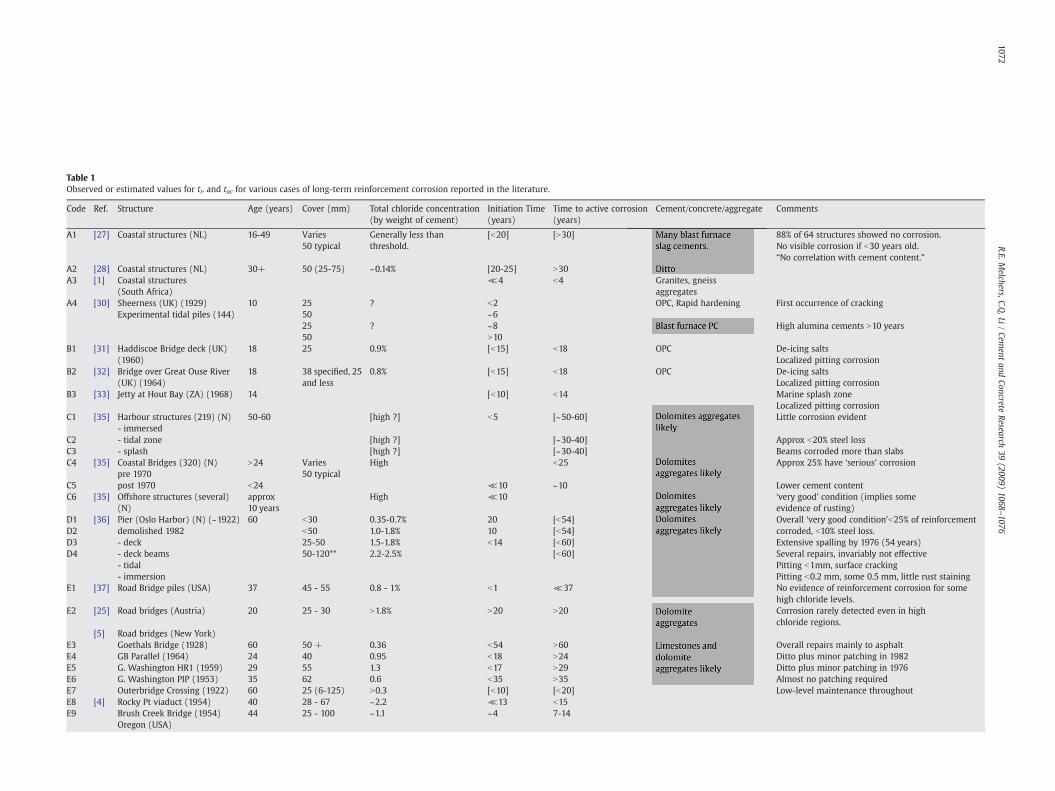
Table 1Observed or estimated values for ti. and tac for various cases of long-term reinforcement corrosion reported in the literature.
Code Ref. Structure Age (years) Cover (mm) Total chloride concentration(by weight of cement)
Initiation Time(years)
Time to active corrosion(years)
Cement/concrete/aggregate Comments
A1 [27] Coastal structures (NL) 16-49 Varies50 typical
Generally less thanthreshold.
[b20] [N30] 88% of 64 structures showed no corrosion.No visible corrosion if b30 years old.“No correlation with cement content.”
A2 [28] Coastal structures (NL) 30+ 50 (25-75) ~0.14% [20-25] N30A3 [1] Coastal structures
(South Africa)≪4 b4 Granites, gneiss
aggregatesA4 [30] Sheerness (UK) (1929)
Experimental tidal piles (144)10 25
50? b2
~6OPC, Rapid hardening First occurrence of cracking
2550
? ~8N10
High alumina cements N10 years
B1 [31] Haddiscoe Bridge deck (UK)(1960)
18 25 0.9% [b15] b18 OPC De-icing saltsLocalized pitting corrosion
B2 [32] Bridge over Great Ouse River(UK) (1964)
18 38 specified, 25and less
0.8% [b15] b18 OPC De-icing saltsLocalized pitting corrosion
B3 [33] Jetty at Hout Bay (ZA) (1968) 14 [b10] b14 Marine splash zoneLocalized pitting corrosion
C1 [35] Harbour structures (219) (N)- immersed
50-60 [high ?] b5 [~50-60] Little corrosion evident
C2 - tidal zone [high ?] [~30-40] Approx b20% steel lossC3 - splash [high ?] [~30-40] Beams corroded more than slabsC4 [35] Coastal Bridges (320) (N)
pre 1970N24 Varies
50 typicalHigh b25 Approx 25% have ‘serious’ corrosion
C5 post 1970 b24 ≪10 ~10 Lower cement contentC6 [35] Offshore structures (several)
(N)approx10 years
High ≪10 ‘very good’ condition (implies someevidence of rusting)
D1D2D3D4
[36] Pier (Oslo Harbor) (N) (~1922)demolished 1982- deck- deck beams- tidal- immersion
60 b30b5025-5050-120**
0.35-0.7%1.0-1.8%1.5-1.8%2.2-2.5%
2010b14
[b54][b54][b60][b60]
Overall ‘very good condition’b25% of reinforcementcorroded, b10% steel loss.Extensive spalling by 1976 (54 years)Several repairs, invariably not effectivePitting b1mm, surface crackingPitting b0.2 mm, some 0.5 mm, little rust staining
E1 [37] Road Bridge piles (USA) 37 45 - 55 0.8 - 1% b1 ≪37 No evidence of reinforcement corrosion for somehigh chloride levels.
E2 [25] Road bridges (Austria) 20 25 - 30 N1.8% N20 N20 Corrosion rarely detected even in highchloride regions.
[5] Road bridges (New York)E3E4E5E6
Goethals Bridge (1928)GB Parallel (1964)G. Washington HR1 (1959)G. Washington PIP (1953)
60242935
50 +405562
0.360.951.30.6
b54b18b17b35
N60N24N29N35
Overall repairs mainly to asphaltDitto plus minor patching in 1982Ditto plus minor patching in 1976Almost no patching required
E7 Outerbridge Crossing (1922) 60 25 (6-125) N0.3 [b10] [b20] Low-level maintenance throughoutE8E9
[4] Rocky Pt viaduct (1954)Brush Creek Bridge (1954)Oregon (USA)
4044
28 - 6725 - 100
~2.2~1.1
≪13~4
b157-14
1072R.E.M
elchers,C.Q.Li
/Cem
entand
ConcreteResearch
39(2009)
1068–1076
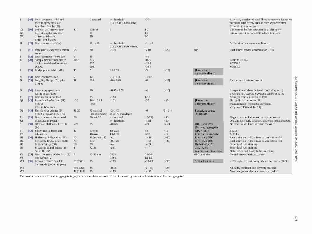
Table 1 (continued)
Code Ref. Structure Age (years) Cover (mm) Total chloride concentration(by weight of cement)
Initiation Time(years)
Time to active corrosion(years)
Cement/concrete/aggregate Comments
F [49] Test specimens, tidal andmarine spray cycles atAberdeen Beach (UK)
0 upward ≫ threshold([Cl-]/[OH-] 320≫0.61)
N3.3 Randomly distributed steel fibres in concrete. Extensivecorrosion only of very outside fibre segments after3 months (i.e. zero cover)
G1G2G3
[50] Prisms (UK) atmospherehigh strength rusty steelditto - grit-blastedditto - grit-blasted
10 10 & 201020
? 1-21-22-3
ti measured by first appearance of pitting onreinforcement surface. CaCl added to mixes.
H [39] Test specimens (slabs) 10 → 40 ≫ threshold([Cl-]/[OH-] 3-20≫0.61)
~1 → 2 Artificial salt exposure conditions.
I [51] Jetty piles (Singapore) splashzone
24 70 ~1.4% [5-10] [~20] OPC Rust stains, cracks, delamination ~30%
J [52] Test specimens Tokyo Bay 5 25 ≪5K [20] Sample beams from bridge
decks - undefined locations(USA).
40 ? 27.247.569.5
b0.72b1.84b3.54
Beam # 18512.0# 2859.6# 3859.6
L [53] Bridge piles (tidal) (MX) 15 ? 0.4-2.9% b5 [N15]
M [54] Test specimens (MX) 2 32 ~1.2-3.6% 0.5-0.8N [55] Long Key Bridge (FL) piles
(1980)17 100 ~0.4-2.4% b6 [N17] Epoxy coated reinforcement
O [56] Laboratory specimensRange of salinities
20 b0.05 - 2.5% b4 [~10] Irrespective of chloride levels (including zero)obtained ‘unacceptable average corrosion rates’
P [57] Test beams under load 25 ~1.5% 1-1.5 Averages from a number of testsQ1 [43] Escambia Bay bridges (FL)
(1966)Piles in tidal zone
~30 26.4 - 2.84(ave.)
~1.2% b30 N30 No significant corrosion. PRmeasurements -‘negligible corrosion’Very low chloride diffusivity.
Q2 [43] Florida Keys bridges (5)(1980-2) splash zone (FL)
18-20 76 nominal(see comments)
~2.4-4%at 50-76 mm depth
b6 6 - 9 +
R1 [29] Test specimens (immersed 30 20, 40, 70 N threshold [15-25] N30 Slag cement and alumina cement concretesR2 in natural seawater) ≫ threshold [b15] b30 OPC and high early strength, moderate heat concretes.S [58] Offshore platform - Brent B
(N)~20 75 ~0.07% ~20 ≫20 No external evidence of rebar corrosion
T1T2
[42] Experimental beams inlaboratory
17 10 min40 max
1.8-2.2%1.3-1.9%
4-68-12
N17N17
B2CL2 -A1CL1 -
U1 [26] Hathaway Bridge piles (76) 42 31 (mainly)-50 low [~b35] [b40] Rust stains on ~10%, minor delamination b3%U2 Pensacola Bridge piles (908) 43 23.3 ~0.4-2% [~b35] [b40] Rust stains on ~10%, minor delamination b3%U3 Brooks Bridge (30) 39 29 low [~b30] Superficial rust stainingU4 St George Island Bridge (15)
All in FL(USA)1 72-89 negl. b1 Superficial rust staining
Note: River rock likely to be limestone.V1V2
[59] Test specimens (Cabo Raso (P)and La Voz (V)
2 15-30 mm 0.42%0.89%
0.8-0.91.8-1.9
OPC or similar Coastal atmospheric exposure
W1 [10] Arbroath, North Sea, UKbalustrade (1000 samples)
63 (1943) 25 ~1.9% ~20-63 [N30] b10% replaced, rest no significant corrosion (2006)
W2 49 (1968) 25 ~0.5% [5 - 15] [b25] All badly corroded and severely crackedW3 14 (1993) 25 ~1.8% [≪10] b10 Most badly corroded and severely cracked
The column for cement/concrete aggregate is grey where ever there was use of blast furnace slag cement or limestone or dolomite aggregates.
1073R.E.M
elchers,C.Q.Li
/Cem
entand
ConcreteResearch
39(2009)
1068–1076
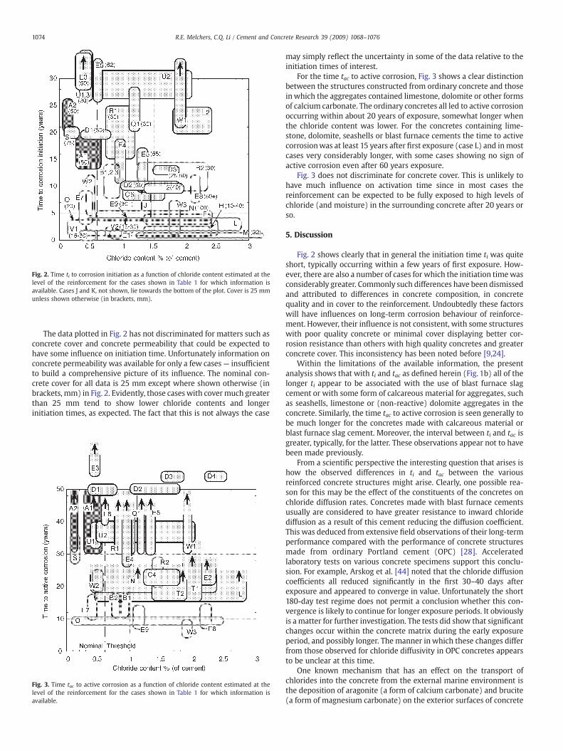
Fig. 2. Time ti to corrosion initiation as a function of chloride content estimated at thelevel of the reinforcement for the cases shown in Table 1 for which information isavailable. Cases J and K, not shown, lie towards the bottom of the plot. Cover is 25 mmunless shown otherwise (in brackets, mm).
1074 R.E. Melchers, C.Q. Li / Cement and Concrete Research 39 (2009) 1068–1076
The data plotted in Fig. 2 has not discriminated for matters such asconcrete cover and concrete permeability that could be expected tohave some influence on initiation time. Unfortunately information onconcrete permeability was available for only a few cases— insufficientto build a comprehensive picture of its influence. The nominal con-crete cover for all data is 25 mm except where shown otherwise (inbrackets, mm) in Fig. 2. Evidently, those caseswith covermuch greaterthan 25 mm tend to show lower chloride contents and longerinitiation times, as expected. The fact that this is not always the case
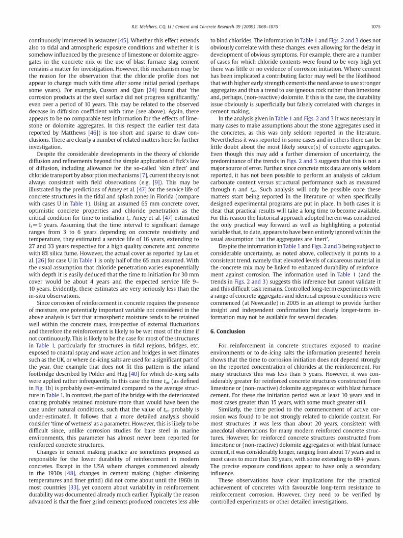
Fig. 3. Time tac to active corrosion as a function of chloride content estimated at thelevel of the reinforcement for the cases shown in Table 1 for which information isavailable.
may simply reflect the uncertainty in some of the data relative to theinitiation times of interest.
For the time tac to active corrosion, Fig. 3 shows a clear distinctionbetween the structures constructed from ordinary concrete and thoseinwhich the aggregates contained limestone, dolomite or other formsof calcium carbonate. The ordinary concretes all led to active corrosionoccurring within about 20 years of exposure, somewhat longer whenthe chloride content was lower. For the concretes containing lime-stone, dolomite, seashells or blast furnace cements the time to activecorrosionwas at least 15 years after first exposure (case L) and inmostcases very considerably longer, with some cases showing no sign ofactive corrosion even after 60 years exposure.
Fig. 3 does not discriminate for concrete cover. This is unlikely tohave much influence on activation time since in most cases thereinforcement can be expected to be fully exposed to high levels ofchloride (and moisture) in the surrounding concrete after 20 years orso.
5. Discussion
Fig. 2 shows clearly that in general the initiation time ti was quiteshort, typically occurring within a few years of first exposure. How-ever, there are also a number of cases for which the initiation timewasconsiderably greater. Commonly such differences have been dismissedand attributed to differences in concrete composition, in concretequality and in cover to the reinforcement. Undoubtedly these factorswill have influences on long-term corrosion behaviour of reinforce-ment. However, their influence is not consistent, with some structureswith poor quality concrete or minimal cover displaying better cor-rosion resistance than others with high quality concretes and greaterconcrete cover. This inconsistency has been noted before [9,24].
Within the limitations of the available information, the presentanalysis shows that with ti and tac as defined herein (Fig. 1b) all of thelonger ti appear to be associated with the use of blast furnace slagcement or with some form of calcareous material for aggregates, suchas seashells, limestone or (non-reactive) dolomite aggregates in theconcrete. Similarly, the time tac to active corrosion is seen generally tobe much longer for the concretes made with calcareous material orblast furnace slag cement. Moreover, the interval between ti and tac isgreater, typically, for the latter. These observations appear not to havebeen made previously.
From a scientific perspective the interesting question that arises ishow the observed differences in ti and tac between the variousreinforced concrete structures might arise. Clearly, one possible rea-son for this may be the effect of the constituents of the concretes onchloride diffusion rates. Concretes made with blast furnace cementsusually are considered to have greater resistance to inward chloridediffusion as a result of this cement reducing the diffusion coefficient.This was deduced from extensive field observations of their long-termperformance compared with the performance of concrete structuresmade from ordinary Portland cement (OPC) [28]. Acceleratedlaboratory tests on various concrete specimens support this conclu-sion. For example, Arskog et al. [44] noted that the chloride diffusioncoefficients all reduced significantly in the first 30–40 days afterexposure and appeared to converge in value. Unfortunately the short180-day test regime does not permit a conclusion whether this con-vergence is likely to continue for longer exposure periods. It obviouslyis a matter for further investigation. The tests did show that significantchanges occur within the concrete matrix during the early exposureperiod, and possibly longer. The manner inwhich these changes differfrom those observed for chloride diffusivity in OPC concretes appearsto be unclear at this time.
One known mechanism that has an effect on the transport ofchlorides into the concrete from the external marine environment isthe deposition of aragonite (a form of calcium carbonate) and brucite(a form of magnesium carbonate) on the exterior surfaces of concrete
1075R.E. Melchers, C.Q. Li / Cement and Concrete Research 39 (2009) 1068–1076
continuously immersed in seawater [45]. Whether this effect extendsalso to tidal and atmospheric exposure conditions and whether it issomehow influenced by the presence of limestone or dolomite aggre-gates in the concrete mix or the use of blast furnace slag cementremains a matter for investigation. However, this mechanism may bethe reason for the observation that the chloride profile does notappear to change much with time after some initial period (perhapssome years). For example, Cusson and Qian [24] found that ‘thecorrosion products at the steel surface did not progress significantly,’even over a period of 10 years. This may be related to the observeddecease in diffusion coefficient with time (see above). Again, thereappears to be no comparable test information for the effects of lime-stone or dolomite aggregates. In this respect the earlier test datareported by Matthews [46]) is too short and sparse to draw con-clusions. There are clearly a number of related matters here for furtherinvestigation.
Despite the considerable developments in the theory of chloridediffusion and refinements beyond the simple application of Fick's lawof diffusion, including allowance for the so-called ‘skin effect’ andchloride transport by absorptionmechanisms [7], current theory is notalways consistent with field observations (e.g. [9]). This may beillustrated by the predictions of Amey et al. [47] for the service life ofconcrete structures in the tidal and splash zones in Florida (comparewith cases U in Table 1). Using an assumed 65 mm concrete cover,optimistic concrete properties and chloride penetration as thecritical condition for time to initiation ti. Amey et al. [47] estimatedti=9 years. Assuming that the time interval to significant damageranges from 3 to 6 years depending on concrete resistivity andtemperature, they estimated a service life of 16 years, extending to27 and 33 years respective for a high quality concrete and concretewith 8% silica fume. However, the actual cover as reported by Lau etal. [26] for case U in Table 1 is only half of the 65 mm assumed. Withthe usual assumption that chloride penetration varies exponentiallywith depth it is easily deduced that the time to initiation for 30 mmcover would be about 4 years and the expected service life 9–10 years. Evidently, these estimates are very seriously less than thein-situ observations.
Since corrosion of reinforcement in concrete requires the presenceof moisture, one potentially important variable not considered in theabove analysis is fact that atmospheric moisture tends to be retainedwell within the concrete mass, irrespective of external fluctuationsand therefore the reinforcement is likely to be wet most of the time ifnot continuously. This is likely to be the case for most of the structuresin Table 1, particularly for structures in tidal regions, bridges, etc.exposed to coastal spray and wave action and bridges in wet climatessuch as the UK, or where de-icing salts are used for a significant part ofthe year. One example that does not fit this pattern is the inlandfootbridge described by Polder and Hug [40] for which de-icing saltswere applied rather infrequently. In this case the time tac (as definedin Fig. 1b) is probably over-estimated compared to the average struc-ture in Table 1. In contrast, the part of the bridge with the deterioratedcoating probably retained moisture more than would have been thecase under natural conditions, such that the value of tac probably isunder-estimated. It follows that a more detailed analysis shouldconsider ‘time of wetness’ as a parameter. However, this is likely to bedifficult since, unlike corrosion studies for bare steel in marineenvironments, this parameter has almost never been reported forreinforced concrete structures.
Changes in cement making practice are sometimes proposed asresponsible for the lower durability of reinforcement in modernconcretes. Except in the USA where changes commenced alreadyin the 1930s [48], changes in cement making (higher clinkeringtemperatures and finer grind) did not come about until the 1960s inmost countries [33], yet concern about variability in reinforcementdurability was documented already much earlier. Typically the reasonadvanced is that the finer grind cements produced concretes less able
to bind chlorides. The information in Table 1 and Figs. 2 and 3 does notobviously correlate with these changes, even allowing for the delay indevelopment of obvious symptoms. For example, there are a numberof cases for which chloride contents were found to be very high yetthere was little or no evidence of corrosion initiation. Where cementhas been implicated a contributing factor may well be the likelihoodthat with higher early strength cements the need arose to use strongeraggregates and thus a trend to use igneous rock rather than limestoneand, perhaps, (non-reactive) dolomite. If this is the case, the durabilityissue obviously is superficially but falsely correlated with changes incement making.
In the analysis given in Table 1 and Figs. 2 and 3 it was necessary inmany cases to make assumptions about the stone aggregates used inthe concretes, as this was only seldom reported in the literature.Nevertheless it was reported in some cases and in others there can belittle doubt about the most likely source(s) of concrete aggregates.Even though this may add a further dimension of uncertainty, thepredominance of the trends in Figs. 2 and 3 suggests that this is not amajor source of error. Further, since concrete mix data are only seldomreported, it has not been possible to perform an analysis of calciumcarbonate content versus structural performance such as measuredthrough ti and tac. Such analysis will only be possible once thesematters start being reported in the literature or when specificallydesigned experimental programs are put in place. In both cases it isclear that practical results will take a long time to become available.For this reason the historical approach adopted hereinwas consideredthe only practical way forward as well as highlighting a potentialvariable that, to date, appears to have been entirely ignored within theusual assumption that the aggregates are ‘inert’.
Despite the information in Table 1 and Figs. 2 and 3 being subject toconsiderable uncertainty, as noted above, collectively it points to aconsistent trend, namely that elevated levels of calcareous material inthe concrete mix may be linked to enhanced durability of reinforce-ment against corrosion. The information used in Table 1 (and thetrends in Figs. 2 and 3) suggests this inference but cannot validate itand this difficult task remains. Controlled long-term experiments witha range of concrete aggregates and identical exposure conditions werecommenced (at Newcastle) in 2005 in an attempt to provide furtherinsight and independent confirmation but clearly longer-term in-formation may not be available for several decades.
6. Conclusion
For reinforcement in concrete structures exposed to marineenvironments or to de-icing salts the information presented hereinshows that the time to corrosion initiation does not depend stronglyon the reported concentration of chlorides at the reinforcement. Formany structures this was less than 5 years. However, it was con-siderably greater for reinforced concrete structures constructed fromlimestone or (non-reactive) dolomite aggregates or with blast furnacecement. For these the initiation period was at least 10 years and inmost cases greater than 15 years, with some much greater still.
Similarly, the time period to the commencement of active cor-rosion was found to be not strongly related to chloride content. Formost structures it was less than about 20 years, consistent withanecdotal observations for many modern reinforced concrete struc-tures. However, for reinforced concrete structures constructed fromlimestone or (non-reactive) dolomite aggregates or with blast furnacecement, it was considerably longer, ranging from about 17 years and inmost cases to more than 30 years, with some extending to 60+ years.The precise exposure conditions appear to have only a secondaryinfluence.
These observations have clear implications for the practicalachievement of concretes with favourable long-term resistance toreinforcement corrosion. However, they need to be verified bycontrolled experiments or other detailed investigations.
1076 R.E. Melchers, C.Q. Li / Cement and Concrete Research 39 (2009) 1068–1076
Acknowledgements
The authors acknowledge the financial support provided by theUK Engineering and Physical Sciences Research Council (Grant No. EP/E00444X/01) and the Australian Research Council (Grant DP0451308).The extensive and excellent service provided by the Inter-library Loanssection of the Auchmuty Library at The University of Newcastle isappreciatedandmuch facilitated the preparation of thismanuscript. Theauthors acknowledge the helpful and constructive comments from thereferees.
References
[1] D.A. Lewis, W.J. Copenhagen, The corrosion of reinforcing steel in concrete inmarine atmospheres, Corrosion (NACE) 15 (7) (1959) 382t–388t.
[2] C.M. Wakeman, E.V. Dockweiler, H.E. Stover, L.L. Whiteneck, Use of concrete inmarine environments, Proc ACI 54 (4) (1958) 841–856.
[3] J.L. Beaton, R.F. Stratfull, Environmental influence on corrosion of reinforcing inconcrete bridge substructures, Highway Research Record 14 (1963) 60–78.
[4] S.D. Cramer, B.S. Covino Jr, S.J. Bullard, G.R. Holcomb, J.H. Russell, F.J. Nelson, H.M.Laylor, S.M. Soltesz, Corrosion prevention and remediation strategies for reinforcedconcrete coastal bridges, Cement and Concrete Composites 24 (1) (2002) 101–117.
[5] B. Burkowsky, J. Englot, Analyzing good deck performance on Port Authoritybridges, Concrete International 10 (11) (1988) 25–33.
[6] A. Bentur, S. Diamond, N. Berke, Steel Corrosion in Concrete: Fundamental and CivilEngineering Practice, E&FN Spon, London, 1997.
[7] M.G. Richardson, Fundamentals of Durable Reinforced Concrete, SponPress, London,2002.
[8] L. Bertolini, B. Elsener, P. Pedeferri, R. Polder, Corrosion of steel in concrete, Wiley-VCH, Weinheim, 2004.
[9] B. Borgard, C.Warren, S. Somayaji, R.Heidersbach,Mechanismsof corrosion of steel inconcrete, in: N.S. Berke, V. Chaker, D. Whiting (Eds.), Corrosion rates of Steel inConcrete, ASTM STP 1065, American Society for Testing and Materials, Philadelphia,1990, pp. 174–188.
[10] Melchers RE and Li CQ. (2008). Observations and crack width statistics for a 63-yearold reinforced concrete promenade railing exposed to the North Sea (to appear).
[11] O.E. Gjorv, Thin underwater concrete structures, Journal of the ConstructionDivision, ASCE 96 (CO1) (1970) 9–17.
[12] C.L. Page, K.W. Treadaway, Aspects of the electrochemistry of steel in concrete,Nature 297 (1982) 109–115 May.
[13] G. Sergi, S.W. Yu, C.L. Page, Diffusion of chloride and hydroxyl ions in cementitiousmaterials exposed to a saline environment, Magazine Concrete Research 44 (158)(1992) 63–69.
[14] A.A. Sagues, E.I. Moreno, C. Andrada, Evolution of pH during in-situ leaching insmall concrete cavities, Cement and Concrete Research 27 (11) (1997) 1747–1759.
[15] T. Yonezawa, V. Ashworth, R.P.M. Procter, Pore solution composition and chlorideeffects on the corrosion of steel in concrete, Corrosion 44 (7) (1988) 489–499.
[16] G.K. Glass, N.R. Buenfeld, Chloride induced corrosion of steel in concrete, Progressin Structural Engineering and Materials 2 (4) (2000) 448–458.
[17] Z.P. Bazant, Physical model for steel corrosion in concrete sea structures — theory,Journal of the Structural Division ASCE 105 (ST6) (1979) 1137–1153.
[18] B. Huet, V. L'Hostis, G. Santarini, D. Feron, H. Idrissi, Steel corrosion in concrete:determinist modeling of cathodic reaction as a function of water saturation degree,Corrosion Science 49 (2007) 1918–1932.
[19] K. Tuuti, Corrosion of steel in concrete, Research Report No 4, Swedish Cement andConcrete Research Institute, Stockholm, 1982, pp. 17–21.
[20] R.E. Weyers, Corrosion service life model concrete structures, in: W.F. Silva-Araya,O.T. De Rincon, L.P. O'Neill (Eds.), Repair and Rehabilitation of Reinforced ConcreteStructures: The State of the Art, ASCE, Reston, VA, 1997, pp. 105–119.
[21] R.B. Polder, M.R. de Rooij, Durability of marine concrete structures — fieldinvestigations and modelling, Heron 50 (3) (2005) 133–153.
[22] C.M. Hansson, P.T. Seabrook, T.D. Marcotte, In-place corrosion monitoring,Concrete International 26 (7) (2004) 59–65.
[23] R.E. Melchers, C.Q. Li, Phenomenological modelling of corrosion loss of steel rein-forcement in marine environments, ACI Materials Journal 103 (1) (2006) 25–32.
[24] D. Cusson, S. Qian, Corrosion inhibiting systems for concrete bridges — 10 years offield performance evaluation, in: F. Toutlemonde, et al., (Eds.), Proc. CONSEC'07,Concrete under Severe Conditions, Laborataire Central des Ponts et Chaussees,Paris, 2007, pp. 463–472, ISSN: 1626-4704.
[25] W. Lukas, Relationship between chloride content in concrete and corrosion inuntensioned reinforcement on Austrian bridges and concrete road surfacings,Betonwerk und Fertigteil-Technik 51 (11) (1985) 730–734.
[26] K. Lau, A.A. Sagues, L. Yao, R.G. Powers, Corrosion performance of concrete cylinderpiles, Corrosion 63 (4) (2007) 366–378.
[27] J.G. Wiebenga, Durability of concrete structures along the North Sea coast of theNetherlands, American Concrete Institute SP65 (1980) 437–452.
[28] J. Bijen, Blast Furnace Slag Cement of Durable Marine Structures, VNC/BetonPrisma, 's-Hertogenbosch, The Netherlands, 1996.
[29] T.U. Mohammed, H. Hamada, T. Yamaji, Concrete after 30 years of exposure— Part11: chloride ingress and corrosion of steel bars, ACI Materials Journal 101 (1)(2004) 13–18.
[30] F.M. Lea, C.M.Watkins, The Durability of Reinforced Concrete in Seawater (TwentiethReport of the Sea Action Committee of the Institution of Civil Engineers), ResearchPaper No. 30, National Building Studies, Department of Scientific and IndustrialResearch (Building Research Station), HMSO, London, 1960.
[31] P.G. Cavalier, P.R. Vassie, Investigation andrepair of reinforcement corrosion inabridgedeck, Proceedings of the Institution of Civil Engineers, Part 170 (1981) 461–480.
[32] P.G. Cavalier, P.R. Vassie, et al., Discussion: investigation and repair of reinforce-ment corrosion in a bridge deck, Proceedings of the Institution of Civil Engineers,Part 1 72 (1982) 401–419.
[33] A.T. Corish, P.J. Jackson, Portland cement properties — past and present, Concrete16 (7) (1982) 16–18.
[34] P.J. Nixon, D.C. Spooner, Concrete proof for British cement, Concrete 27 (5) (1993)41–44.
[35] O.D. Gjorv, Steel corrosion in concrete structures exposed to Norwegian marineenvironment, Concrete International 16 (4) (1994) 35–39.
[36] O.D. Gjorv, N. Kashino, Durability of a 60-year-old reinforced concrete pier in Osloharbor, Materials Performance 25 (2) (1986) 18–26.
[37] J.L. Beaton, D.L. Spellman, R.F. Stratfull, Corrosion of steel in continuously submergedreinforced concrete piling, Highway Research Record 204 (1967) 11–21.
[38] M.B. Roberts, C. Atkins, V. Hogg, C. Middleton, A proposed empirical corrosionmodel for reinforced concrete, Proceedings of the Institution of Civil Engineers.Structures and Buildings 140 (1) (2000) 1–11.
[39] P. Lambert, C.L. Page, P.R.W. Vassie, Investigations of reinforcement corrosion. 2.Electrochemical monitoring of steel in chloride-contaminated concrete, Materialsand Structures 24 (1991) 351–358.
[40] R.B. Polder, A. Hug, Penetration of chloride from de-icing salt into concrete from a30 year old bridge, Heron 45 (2) (2000) 109–124.
[41] A. Castel, T. Vidal, R. Francois, G. Arliguie, Influence of steel — concrete interfacequality on reinforcement corrosion induced by chlorides, Magazine of ConcreteResearch 55 (2) (2003) 151–159.
[42] A. Castel, T. Vidal, R. Zhang, R. Francois, V. Sirivivananon, Initiation and propagationphase in reinforced concrete corrosion due to long term exposure in salineenvironment, in: F. Toutlemonde, et al., (Eds.), Proc. CONSEC'07, Concrete underSevereConditions, LaborataireCentral desPonts etChaussees, Paris, 2007, pp. 307–314,ISSN: 1626-4704.
[43] A.A. Sagues, Modeling the effects of corrosion on the lifetime of extended reinforcedconcrete structures, Corrosion 59 (10) (2003) 854–866.
[44] V. Arskog, M. Ferreira, G. Liu, O.E. Gjorv, Effect of cement type on the resistance ofconcrete against chloride penetration, in: F. Toutlemonde, et al., (Eds.), Proc.CONSEC'07, Concrete under Severe Conditions, Laborataire Central des Ponts etChaussees, Paris, 2007, pp. 367–374, 1626-4704.
[45] N.R. Buenfeld, J.B. Newman, The permeability of concrete in a marine environ-ment, Magazine of Concrete Research 36 (127) (1984) 67–80.
[46] J.D. Matthews, Performance of limestone filler cement concrete, in: R.K. Dhir, M.R.Jones (Eds.), Euro-cement: Impact of ENV207 on Concrete Construction, E&F Spon,London, 1994, pp. 113–147.
[47] S.L. Amey, D.A. Johnson, M.A. Mittenberger, H. Farzam, Predicting the service life ofconcrete marine structures: an environmental methodology, ACI Materials Journal95 (2) (1998) 205–214.
[48] P.K. Mehta, R.W. Burrows, Building durable structures in the 21st century, ConcreteInternational 23 (3) (2001) 57–63.
[49] P.S. Mangat, K. Gurusamy, Corrosion resistance of steel fibres in concrete undermarine exposure, Cement and Concrete Research 18 (1988) 44–54.
[50] K.W.J. Treadaway, R.N. Cox, B.L. Brown, Durability of corrosion resisting steel inconcrete, Proc. Inst. Civ. Eng., Part 1 86 (1989) 305–331.
[51] K.C. Liam, S.K. Roy, D.O. Northwood, Chloride ingress measurements and corrosionpotentialmapping studyof a24-year-old reinforced concrete jetty structure in a tropicalmarine environment, Magazine of Concrete Research 44 (160) (1992) 205–215.
[52] K. Suda, S. Misra, K. Motohashi, Corrosion products of reinforcing bars embeddedin concrete, Corrosion Science 35 (5–8) (1993) 1543–1549.
[53] J.J. Carpio, T. Perez-Lopez, J. Genesca, L. Martinez, Rehabilitation of a damagedreinforced concrete bridge in a marine environment, in: W.F. Silva-Araya, O.T. DeRincon, L.P. O'Neill (Eds.), Repair and Rehabilitation of Reinforced ConcreteStructures: The State of the Art, ASCE, Reston, VA, 1997, pp. 43–59.
[54] P. Castro, L. Veleva, M. Balancan, Corrosion of reinforced concrete in tropical marineenvironment and in accelerated tests, Construction and Building Materials 11 (2)(1997) 75–81.
[55] W.H. Hartt, S.K. Lee, J.E. Costa, Condition assessment and deterioration rateprojection for chloride contaminated reinforced concrete structures, in: W.F. Silva-Araya, O.T. De Rincon, L.P. O'Neill (Eds.), Repair and Rehabilitation of ReinforcedConcrete Structures: The State of the Art, ASCE, Reston, VA, 1997, pp. 82–104.
[56] P. Novak, R. Mala, L. Joska, Influence of pre-rusting on steel corrosion in concrete,Cement and Concrete Research 31 (2001) 589–593.
[57] C.Q. Li, Initiation of chloride-induced reinforcement corrosion in concrete structuralmembers — prediction, ACI Structural Journal 99 (2) (2002) 133–141.
[58] O. Sengul, O.E. Gjorv, Chloride penetration into a 20 year old North Sea concreteplatform, in: F. Toutlemonde, et al., (Eds.), Proc. CONSEC'07, Concrete under SevereConditions, Laborataire Central des Ponts et Chaussees, Paris, 2007, pp. 107–116,1626-4704.