Embed Size (px)
Citation preview
TTEECCHHNNIICCAALL MMAANNUUAALLRREEFFRRIIGGEERRAATTEEDD AAIIRR DDRRYYEERR
NC SERIES NON-CYCLINGNCG MODELS 75 - 150
TABLE OF CONTENTS PAGE
1. INTRODUCTION 12. ABBREVIATED WARRANTY 13. REFRIGERATED DRYER NOMENCLATURE 24. RECEIVING AND INSPECTION 25. SAFETY AND OPERATION PRECAUTIONS 46. PRINCIPLES OF OPERATION 77. INSTALLATION AND INITIAL START-UP 108. SCHEDULED MAINTENANCE 129. TROUBLESHOOTING 14
10. WIRING DIAGRAMS 1611. GENERAL ARRANGEMENT 2112. PARTS IDENTIFICATION 2213. ENGINEERING SPECIFICATIONS 23
ZEKS Compressed Air Solutions1302 Goshen Parkway
West Chester, Pennsylvania 19380
610-692-9100 800-888-2323 FAX 610-692-9192WWW.ZEKS.COM
NCTM 75-150G-CSTAT V03/04
COMPRESSED AIR SOLUTIONSTM
PATENT # 6,186,223
C

1
1. INTRODUCTION
ZEKS Non-Cycling refrigerated air dryers remove moisture, oil vapor and other contaminantsfrom compressed air. These contaminants are detrimental to pneumatically operatedappliances, controls, instruments, machinery and tools. The dryer cools compressed air witha refrigeration unit to a temperature at which moisture in the air is condensed and separatedfrom the air stream. This temperature is approximately 36°F (2.2°C), and is known as dewpoint. This dryer can be easily installed in various pneumatic systems in which dry air isrequired or desired. Please refer to Principles of Operation for complete operating details.• For warning label information with French translations, refer to pages 4 & 5.• Pur obtenir i’informatione des etiquettes dangereuses avec la traductione en francais, s’il vous plait consul
ter les pages 4 & 5.
2. ABBREVIATED WARRANTY
Standard ZEKS Non-Cycle refrigerated dryers are warrantied to be free of defects in materialand workmanship for a period of 12 months from the date of start-up or 18 months from thedate of shipment. To validate the warranty, the registration card must be completed andreturned to ZEKS at the time of unit start-up. If no registration information is returned, thewarranty becomes effective on the original date of shipment from ZEKS Compressed AirSolutions.
Equipment must be installed and operated in accordance with ZEKS’ recommendations.ZEKS’ liability is limited to repair, replacement, or refund of purchase price, in kind, during thewarranty time period stated above. In no event shall ZEKS be liable for incidental orconsequential damages, even if the possibility of such incidental or consequential damageshas been made known to ZEKS Compressed Air Solutions. Normal maintenance andconsumable parts are not covered by this warranty.
EXCHANGERSNCG series dryers that utilize CFX® heat exchanger technology are covered by a prorated warranty for the replacement of the exchanger extending a maximum of 120 months(10 years). Following the standard warranty terms, the available warranty is as stated below.This prorated warranty applies to replacement of exchangers only and does not cover anylabor expense.
Prorated coverage of list prices: 13 to 48 months 100%49 to 60 months 70%61 to 72 months 50%73 to 84 months 30%85 to 96 months 20%97 to 120 months 10%

2
REFRIGERANT COMPRESSORSZEKS’ refrigerated dryer warranty includes prorated warranty for the replacement of therefrigerant compressor extending a maximum of 60 months (5 years). Following the standardwarranty terms, the available prorated warranty is as stated below. This prorated warrantyapplies to replacement compressors only and does not cover any labor expense.
Prorated coverage of list prices: 13 to 18 months 100%19 to 24 months 70%25 to 36 months 50%37 to 48 months 30%49 to 60 months 10%
Freight and labor coverage varies internationally. Contact your distributor for WarrantyPolicy limitations and additional information regarding warranty coverage.
The warranties expressed above are in lieu of and exclusive of all other warranties. Thereare no other warranties, expressed or implied, except as stated herein. There are no impliedwarranties of merchantability or fitness for a particular purpose, which are specificallydisclaimed.
3. REFRIGERATED DRYER NOMENCLATURE
NOMINAL*FLOW DESIGN CONDENSERSCFM TYPE SERIES TYPE POWER OPTIONS75 thru 150 NC = Non-Cycle G A=Air Cooled 1=115-1-60
2=230-1-603=220-1-50
O = STANDARD O = STANDARDW = WEATHERPROOF 1 = DPC™ Controller
* Nominal flows indicated are for 100°F inlet temperature,100°F ambient temperature and 100psig compressed air pressure.

3
4. RECEIVING AND INSPECTION
4.1 INSPECTIONUpon receiving your ZEKS air dryer, please inspect the unit closely. If rough handlinghas been detected, please note it on your delivery receipt, especially if the dryer will notbe uncrated immediately. Obtaining the delivery person’s signed agreement to anynoted damage will facilitate insurance claims.
4.2 UNPACKING AND HANDLING
To facilitate handling during shipment, all dryer packages have been mounted on a basethat provides for forklifting between two base channels. Forks should extend all the waythrough forklift channels to reduce unnecessary forces to the dryer during moving.Slings can be used to lift the crates, but spreader bars must be used to prevent theslings from exerting a force against the sides of the crate or the dryer.
Under no circumstances should any person attempt to lift heavy objects withoutproper lifting equipment (i.e. crane, hoist, slings or fork truck). Lifting any unitwithout proper lifting equipment may cause serious injury.
4
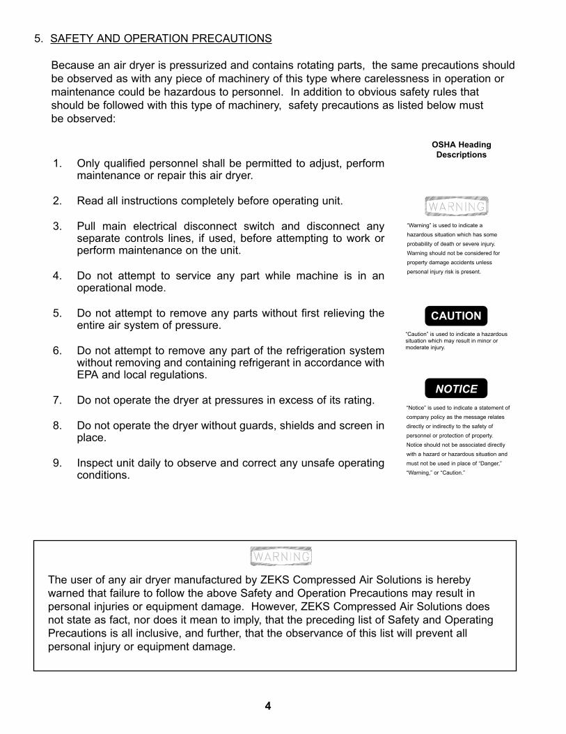
OSHA HeadingDescriptions
“Warning” is used to indicate ahazardous situation which has someprobability of death or severe injury.Warning should not be considered forproperty damage accidents unlesspersonal injury risk is present.
“Notice” is used to indicate a statement ofcompany policy as the message relatesdirectly or indirectly to the safety ofpersonnel or protection of property.Notice should not be associated directlywith a hazard or hazardous situation andmust not be used in place of “Danger,”“Warning,” or “Caution.”
“Caution” is used to indicate a hazardoussituation which may result in minor ormoderate injury.
CAUTION
NOTICE
1. Only qualified personnel shall be permitted to adjust, performmaintenance or repair this air dryer.
2. Read all instructions completely before operating unit.
3. Pull main electrical disconnect switch and disconnect anyseparate controls lines, if used, before attempting to work orperform maintenance on the unit.
4. Do not attempt to service any part while machine is in anoperational mode.
5. Do not attempt to remove any parts without first relieving theentire air system of pressure.
6. Do not attempt to remove any part of the refrigeration systemwithout removing and containing refrigerant in accordance withEPA and local regulations.
7. Do not operate the dryer at pressures in excess of its rating.
8. Do not operate the dryer without guards, shields and screen inplace.
9. Inspect unit daily to observe and correct any unsafe operatingconditions.
The user of any air dryer manufactured by ZEKS Compressed Air Solutions is herebywarned that failure to follow the above Safety and Operation Precautions may result inpersonal injuries or equipment damage. However, ZEKS Compressed Air Solutions doesnot state as fact, nor does it mean to imply, that the preceding list of Safety and OperatingPrecautions is all inclusive, and further, that the observance of this list will prevent allpersonal injury or equipment damage.
5. SAFETY AND OPERATION PRECAUTIONS
Because an air dryer is pressurized and contains rotating parts, the same precautions should be observed as with any piece of machinery of this type where carelessness in operation ormaintenance could be hazardous to personnel. In addition to obvious safety rules thatshould be followed with this type of machinery, safety precautions as listed below mustbe observed:

5
Air Under Pressure Will CauseInjury, Death Or Property Damage.• Do Not Exceed Pressure Rating.• Relieve Press. Before Servicing.• Do Not Modify/Repair/Rework
ASME Coded Pressure VesselsAs Insurance Rating Affected.
! READ INSTRUCTION MANUAL !
HIGH VOLTAGE Can Cause SevereInjury Or Death.• Some circuits may be energized
when switch is off.• Disconnect and lockout ALL
power sources before servicing.
! READ INSTRUCTION MANUAL !
Air Under Pressure Will CauseInjury, Death Or Property Damage• Relieve Press. Before Servicing.• Condensate Drain Discharges
Under Pressure.• Drain Requires Periodic
Cleaning (Service).
! READ INSTRUCTION MANUAL !
L'air sous pression causerades blessures graves, desdégats matériels et peutmême entrainer la mort
Ne pas excéder le taux depression
Relâcher la pression avant lamise en service de l'appareil
Ne pas modifier/réparer ouretravailler
Le taux de pression desvaisseaux est conforme auxrecommendations de l' ASME( American Society ofMechanical Engineers) et peutêtre vérifié lors d'un controle.
LIRE LE MANUELD'INSTRUCTIONS!
La haute tension peutentrainer des blessures gravesou même la mort
Certains circuits peuvent êtrechargés lorsque l'interrupteurest en position "fermé" (off)
· Déconnecter et vérouillerTOUTES les sourcesd'électricité avant la mise enservice de l'appareil
LIRE LE MANUELD'INSTRUCTIONS!
L'air sous pression causerades blessures graves, desdégats matériels ou mêmela mort
Relâcher la pression avantla mise en service del'appareil
· Condenser les tuyaux dedécharges sous pression
· Les tuyaux doivent êtrenettoyés régulièrement(service)
LIRE LE MANUELD'INSTRUCTIONS!

6
Removing fuses will notdisconnect power fromdryer. Always disconnectpower from ALL sourcesbefore performing service.
! READ INSTRUCTION MANUAL !
WARNING ATTENTION !
Retirer les fusibles ne déconnectera pas l'électricitéde l'appareil
TOUJOURS déconnecter toutes les sourcesd'électricité avant la mise en marche de l'appareil
LIRE LE MANUEL D'INSTRUCTIONS!

7
6. PRINCIPLES OF OPERATION
6.1 INTRODUCTIONZEKS Non-Cycling dryers remove moisture, oil vapor and other contaminants fromcompressed air by cooling the air temperature to 36°F (2.2°C). This cooling processcondenses the contaminants into liquid droplets which can then be easily removed fromthe air. The major systems of the dryer which contribute to its operation are thefollowing: Air System, Moisture Removal System, Refrigeration System and theControls System. The following paragraphs describe each of the systems in greaterdetail.
6.2 AIR SYSTEMThis system consists of the dryer components which are in contact with the compressedair. Referring to Figure 1 and following the bold “AIR FLOW”, hot saturated air from thecompressor enters the precooler/reheater where the air temperature is reduced prior toentering the chiller by the cool air exiting the air/moisture separator. This precoolingallows for the use of a smaller refrigeration system. The air then goes into the chillersection where it is further cooled to the desired dew point through direct heat transferwith evaporating refrigerant. The air continues to the separator where the moisture isremoved, thereby allowing the cool, dry air to return to the precooler/reheater. As the airpasses through the precooler/reheater the air temperature is elevated by the warm, wetinlet air. The air exiting the reheater portion of the dryer should be approximately 15-20°F lower than the inlet air temperature based on standard conditions at full rated flow.
6.3 MOISTURE REMOVAL SYSTEMLiquid droplets are removed from the air stream in the separator. As the air andliquid mixture passes through the separator it spins, slows down and then changesdirection. This causes the condensate to fall out of the air stream and collect in thebottom of the separator. The collected liquid is removed from the separator by atimed electric drain. On units equipped with the Z-Trol™ Controller, the electric drainvalve is replaced by a timed solenoid drain valve which is controlled by the Z-Trol™Controller. For units equipped with the solenoid drain valve, refer to the Z-TrolAddendum for details on setting the solenoid valve using the Z-Trol Controller.
FIGURE 1 - FLOW DIAGRAM

8
The standard timed electric drain valve is operated by a solid state timer located on thedrain assembly.
• To obtain the optimum time values for operation of the electric drain valve, set the off-time adjustment knob to five minutes and the on-time adjustment knob to ten seconds.
• After running the unit under full rated flow for approximately 30 minutes, verify thatwhen the electric drain opens, all of the accumulated liquid is discharged and then asmall burst of air.
• If a small amount of liquid and a large amount of air is discharged, decrease the on-time setting or increase the off-time setting. If there is all liquid and no air has beendischarged, increase the on-time setting or decrease the off-time setting.
• The on/off-time settings will vary accordingly to seasonal conditions. During thesummer when more moisture is present in the air system, a shorter on-timeincreasing the valve opening frequency is required. A longer valve off-time may beused during the winter months when moisture levels are lower.
6.4 REFRIGERATION SYSTEMThe Refrigeration System consists of all the components which handle refrigerantR404A. This is a hermetically sealed closed-loop system. Referring to Figure 1 andfollowing the dot-dash “REFRIGERANT FLOW,” refrigerant is shown leaving the chillerevaporator section, which in the process of removing heat is changed from a lowpressure liquid to a low pressure gas. This gas enters the suction side of thecompressor where it is compressed into a high pressure gas. The high pressure gas iscooled in the air or water cooled condenser section becoming a high pressure liquid. Itthen goes through a permanent filter-dryer that ensures the refrigerant system is free ofcontaminants. A small diameter capillary tube meters the refrigerant into the chiller’sevaporator. The pressure is reduced upon entering the chiller evaporator where itremoves heat from the air system. When there are low loads (low air flow rate or inlettemperature), a hot gas valve by-passes the condenser and throttling device (capillarytube). This valve maintains a minimum evaporator pressure of 76 psig, whichcorresponds to a chiller temperature of 34°F, thus preventing freeze-up.
TIMED ELECTRIC DRAIN -FIGURE 2

9
FIGURE 3 - HOT GAS BY-PASS VALVE
Do not rotate Hot Gas By-Pass valve adjustment nut fully clockwise. Full clockwise rotationmay result in refrigerant compressor damage. Any suction pressure setting above 90 psigis not recommended.
CAUTION
For Hot Gas By-Pass Valve adjustment note thefollowing:
• Turning the adjustment screw clockwise raisessuction pressure and exchanger temperature.
• Turning the adjustment screw counter-clockwisereduces suction pressure and exchangertemperature.
• All adjustments should be made without air flow(load) on the dryer.
6.5 CONTROLSZEKS’ Non-Cycling dryers incorporate automatic controls for proper operation. All dryercontrols are preset at the factory. A refrigerant suction pressure gauge is provided asstandard equipment. This gauge monitors the pressure of the refrigerant gas before itenters the compressor. When the refrigeration system is running, the suction pressurewill be controlled between 76 to 85 psig.
Note that for all models with the optional “Compustat™” microprocessor, refer to theCompustat™ Addendum
ZEKS air cooled models utilize a fan cycling switch to control the condensing temperature.This switch controls the condensing temperature by cycling the fan based on refrigerantdischarge pressure. When the unit reaches 275 psig, the fan cycling switch will run thefan until the discharged pressure is reduced to 195 psig.
All ZEKS Non-Cycling dryers include a Hot Gas By-Pass Valve to maintain suction pressureand temperature. This valve is necessary during low load applications to prevent freeze-upin the chiller section. The normal suction pressure for no load conditions should never dropbelow 72 psig. *This setting may need adjustment to match the load/ambient conditionsencountered.
*This adjustment is not a procedure covered under warranty as it is typically required for applicationspecific conditions.

10
7. INSTALLATION AND INITIAL START-UP
7.1 LOCATION AND MOUNTINGThe dryer must be located in an area where ambient temperature is not likely to exceed113°F (35°C) or be less than 40°F (4.5°C). The dryer must be located in an area thatprovides sufficient clearance from walls and other adjoining equipment to allow easyaccess for servicing and maintenance requirements. A minimum of 18 inches isrequired to allow free air flow to the condenser. Dryer must be installed on a level (<5°slope) sufrace for proper operation.
On installations with relatively steady flow rate, the dryer is normally connected after theair receiver. If loads fluctuate widely, the dryer should be positioned ahead of thereceiver with sufficient storage capacity downstream to prevent excessive air flowthrough the dryer.
7.2 PIPING AND VALVESInstall piping, fittings and accessory items as indicated in Figure 4. For bypass andisolating purposes, valves (A), (B), and (C) may be field installed (not furnished).
ZEKS 75-150 NCG models equipped with either a timed drain valve or optional solenoiddrain valve are furnished with a drain isolation valve (D). The isolation valve permitsmaintenance of the drain valve without isolating air flow to the dryer. To operate dryer,all valves labeled in Figure 4 are to be closed except valves (B), (C) and (D). Valve (A)is used for bypass purposes and valve (E) is for test and manual drain purposes.
7.3 FILTRATIONTo protect the air dryer from residualcompressor oil and to ensure max-imum dryer performance, a prefilter isrecommended. Highly efficientprefilters and afterfilters sized to yourdrying application can be provided byZEKS and are available factoryinstalled. Call your local distributor toselect the filter that best suits yourfiltration requirements. In addition toair filtration, condensate dischargeoil/water separators are available toaddress stringent EPA regulations.
FIGURE 4 - PIPING DIAGRAM
Failure to comply to the above instructions may result in equipment malfunction andwill void warranty.
NOTICE
Always use a backup wrench when making any threaded connection to the dryer.Failure to use a backup wrench may result in damaged tubing and components internal to the cabinet.
NOTICE

11
7.4 ELECTRICAL CONNECTION
Equipment is available in various electrical configurations. Providing power to these unitsis accomplished as follows:
115V/1/60: These units are supplied with a three-wire, 115V cord assembly asstandard. These units need only be plugged into a suitable 115V/1/60Hz poweroutlet.
230V/1/60 &: 220V/1/50: These units are furnished with a power cord with leads fora field installed plug. L1, L2, N & GND are indicated on the leads. Customer isresponsible for furnishing a suitable plug. This plug shall be wired according to theappropriate wiring diagram included in this manual.
A suitable fused disconnect switch or circuit breaker conforming to national and localcode requirements is recommended for all ZEKS equipment. See Section 13 of thismanual for voltage requirements and load data.
7.5 INITIAL START-UPAfter installation or a prolonged shutdown, start the dryer with no air load (no airflow). This enables the dryer to stabilize at its proper operating pressure andtemperature in the shortest time possible (typically within five minutes).
The following conditions should be observed during start-up:
• The suction pressure gauge will typically pull down to between 76 and 85psig. The Hot Gas By-Pass Valve may require adjustment at start-up. Referto Section 6.5 for details.
• The refrigerant discharge pressure will vary as indicated in the controlssection. Refer to section 6.5 for details.
For models with the optional Compustat Controller, refer to addendum.
NOTICE
Care must be used when choosing the circuit of single phase units to ensure that noexcessive voltage variations occur. This may affect the starting of the compressor andin extreme cases may cause a compressor burn out. Maximum allowable voltagevariation is +15% and -10% from rated voltage. Voltage variations exceeding thespecified tolerances will void warranty.
Never wire directly or connect any additional wires to the compressor junction box. Thiswill cause severe system malfunction.
NOTICE
NOTICE

12
• The “High Temp” alarm light will illuminate. The thermostat for this alarm samplesthe chilled compressed air. Shortly after flow has been introduced, the “High Temp”light will go out.
• The “Power On” light will illuminate.
• After a sufficient amount of time, air flow may be slowly introduced to the dryer.
• Set and adjust timed drain operation as described in Section 6.3.
8. SCHEDULED MAINTENANCE
8.1 INTRODUCTIONZEKS’ Non-Cycling refrigerated air dryer requires little maintenance. These dryersutilize hermetically sealed compressors and do not require any lubrication. The fanmotor requires lubrication at both oil ports every six months. However, it isrecommended you inspect and service your dryer at regular intervals to obtain maximumperformance.
8.2 REFRIGERANT CONDENSERFor proper operation, it is essential that the condenser fins remain free of dirt and dust. Therefore, regular cleaning is required. If the dryer is located in an area where dust isexcessive, more frequent inspections and cleaning may be required. An optionalambient air filter can be easily installed outside of the condenser. Contact your localZEKS distributor for details.
8.3 CONDENSATE DISCHARGE SYSTEMOn a minimum of a monthly basis, the operation of the drain should be checked.Periodically, the drain should be removed and cleaned to ensure no debris from thesystem is trapped inside. ZEKS NCG dryers are equipped with a drain isolationvalve,enabling the valves to be cleaned during dryer operation after the drain isolationvalve has been manually closed. The drain valve is located near the solenoid valve andrequires a quarter turn to isolate the drain from system pressure.
If your dryer is installed without a drain isolation valve (filter stop), failure todepressurize the dryer may result in serious injury. Do not remove the drain valvewithout depressurizing the unit.

13
CLEANING INSTRUCTIONS - COMPUSTAT EQUIPPED SOLENOID DRAIN
• Be sure dryer is depressurized or isolationvalve is closed.
• Disconnect drain body from filter stop.• Loosen connector screw to allow the electrical
connector assembly to be removed from theD.I.N. unit solenoid.
• Remove retainer nut and separate the valvebody from the D.I.N. unit solenoid.
• Unthread the plunger tube assembly in acounter-clockwise direction until plungerseparates from valve body.
• Clean beveled washer, thread gasket, springassembly and strainer with soap and water. DoNOT use solvents of any kind, as failure to theseals will occur. Be especially careful to cleanthe center brass orifice and the rubber gasketorifice on the orifice cup with a straight pin.
• Reassemble all drain components after the drain has been cleaned and inspected. Repositionthe orifice hole on the rubber gasket of the orifice cup in the line and closest to the arrowindicated on the valve body.
• Reassemble valve and install in reverse order as described above.
CLEANING INSTRUCTIONS - DRAIN STRAINER
• Be sure dryer is depressurized or isolation....valve is closed.• Unscrew strainer end cap from isolation
valve body.• Remove strainer from isolation valve body.• Clean strainer with soap and water. Do not
use solvents when cleaning strainer.• Reinsert strainer into isolation valve body,
insuring strainer is properly seated.• Attach strainer end cap to isolation valve
body.• Figure shows unit with electric timed drain
valve. Solenoid valve similar.
DRAIN STRAINER DETAIL
SOLENOID VALVE DETAIL

14
9.2 PROBLEM / ACTION GUIDE
PROBLEM
Moisture down stream
SYMPTOM(S)
Dryer is properlycooling air stream(Outlet substantiallycooler than inlet)
POSSIBLECAUSE
Drain failure or timeradjustment is required
Excessive flow
CORRECTIVE ACTION
Dismantle and clean drain and / orstrainer. Repair or replace asnecessary.
Depress “Test” button (“Drain”button on optional solenoid drainwith Z-Trol) - if drain valveoperates, adjust timing.
For optional solenoid drain,depress “Drain” button - if red LEDdrain energized indicator comes onbut valve does not open, ensurewiring connections are secure andpower is being applied to thesolenoid coil. If valve continuesnot to open, clean as described inSection 8.3*
Depress “Test” button on drain - if“ON” indicator does not illuminate,ensure wiring connections aresecure. If valve continues to notoperate, Contact distributor.
For optional solenoid drain,depress “Drain” button - if red LEDdrain energized indicator does notcome on, contact distributor.*
Check inlet and outlet pressuresand system design capacity.Correct cause of excessive flow.
9. TROUBLESHOOTING
9.1 INTRODUCTIONZEKS Non-Cycling dryers are designed for reliable, trouble-free operation. In the event ofany dryer malfunction, the guide shown on the next page has been developed to facilitate problem identification and corrective actions.
Prior to working on the unit, make sure that all circuit breakers or disconnect switchesare tagged off “OUT OF SERVICE”.
An air dryer always operates under pressure. Before any maintenance procedure thatrequires disassembly of any piping, fittings, valves or other components is performed,the dryer must be isolated from the compressed air stream and fully depressurized.

15
PROBLEM
Moisture downstream
High pressuredrop across dryer
SYMPTOM
Inlet and outlettemperatures arethe same
Outlet pressuresubstantially lowerthan inlet pressure
POSSIBLE CAUSE
Dryer by-pass notclosedNo power to thedryerHigh suctionpressureRefrigerant leak
Compressor notrunning
Inlet and outletvalves notcompletely openInlet and outletfilters blocked upSuction pressurebelow 76 psig andunit operating toocoldNo dryer prefilterand heat exchangerhas becomeclogged
CORRECTIVE ACTION
Close by-pass valve
Check power supply andfuses/circuit breakersClean condenser fins
Check suction pressure gaugeand if 0 psig, turn dryer off andcontact your distributorClean condenser finsCheck ambient temperature andreduce below 120°FCheck fan motor if not running,contact your local distributorContact your local distributor forfurther assistance
Open valves
Change filter elements
Adjust suction pressure perSection 6.5
Flush air system as required.Consult your local distributor.

16
10. WIRING DIAGRAMS
Wiri
ng D
iagr
am75
-150
NC
GA
115/
1/60
HZ
Dra
win
g #
TM50
0135
A

17
Wiri
ng D
iagr
am75
-150
NC
GA
230V
/1/6
0HZ
& 22
0V1/
50H
ZD
raw
ing
# TM
5001
39B

18
Wiri
ng D
iagr
am15
0NC
GA
115V
/1/6
0HZ
With
Com
pust
at™
Con
trolle
rD
raw
ing
# TM
5001
37A

19
Wiri
ng D
iagr
am75
-150
NC
GA
230V
/1/6
0HZ
& 22
0V/1
/50H
ZW
ith C
ompu
stat
™ C
ontro
ller
Dra
win
g #
TM50
0141
B

20
Wiring DiagramSingle Phase 60 HZ
EMBRACO Compressor ConnectionsDrawing # 500100-C

21
11. GENERAL ARRANGEMENT
Gen
eral
Arra
ngem
ent
Dra
win
g #T
M50
0202

22
12.
PAR
TS ID
ENTI
FIC
ATIO
N75
NC
G10
0NC
G12
5NC
G15
0NC
G11
0/1/
6023
0/1/
6022
0/1/
5011
0/1/
6023
0/1/
6022
0/1/
5011
0/1/
6023
0/1/
6022
0/1/
5011
0/1/
6023
0/1/
6022
0/1/
501
Exc
hang
er A
ssy
7477
2574
7725
7477
2574
7725
7477
2574
7725
7477
9174
7791
7477
9174
7791
7477
9174
7791
2E
lect
ric D
rain
Val
ve68
3242
6832
4368
3243
6832
4268
3243
6832
4368
3242
6832
4368
3243
6832
4268
3243
6832
433
Com
pres
sor
6832
1068
3208
6832
0968
3211
6832
7168
3212
6825
8868
2592
6825
8968
2588
6825
9268
2589
4C
ompr
esso
r Ele
ctric
s K
it68
3283
6832
8168
3282
6832
8468
3286
6832
8568
3016
6830
2068
3017
6830
1668
3020
6830
175
Con
dens
er69
7172
6971
7269
7172
6971
7269
7172
6971
7269
7172
6971
7269
7172
6971
7269
7172
6971
726
Fan
Mot
or69
7304
6000
8360
0083
6973
0460
0083
6000
8369
7304
6000
8360
0083
6973
0460
0083
6000
837
Fan
Bla
de69
7186
6971
8669
7186
6971
8669
7186
6971
8669
7186
6971
8669
7186
6971
8669
7186
6971
868
Fan
Bra
cket
7478
9974
7899
7478
9974
7899
7478
9974
7899
7478
9974
7899
7478
9974
7899
7478
9974
7899
9Fi
lter D
ryer
6980
4569
8045
6980
4569
8045
6980
4569
8045
6980
4569
8045
6980
4569
8045
6980
4569
8045
10G
auge
(Suc
tion)
6826
0268
2602
6826
0268
2602
6826
0268
2602
6826
0268
2602
6826
0268
2602
6826
0268
2602
11S
witc
h, O
n/O
ff69
9611
6997
5469
9754
6996
1169
9754
6997
5469
9611
6997
5469
9754
6996
1169
9754
6997
5412
Ligh
t, H
i Tem
p69
7297
6973
0069
7300
6972
9769
7300
6973
0069
7297
6973
0069
7300
6972
9769
7300
6973
0013
Tsta
t (H
igh
Tem
p)69
7277
6972
7769
7277
6972
7769
7277
6972
7769
7277
6972
7769
7277
6972
7769
7277
6972
7714
Pow
er C
ord
6815
3268
3232
6832
3268
1532
6832
3268
3232
6815
3268
3232
6832
3268
1532
6832
3268
3232
15H
ot G
as B
y-P
ass
6973
4169
7341
6973
4169
7341
6973
4169
7341
6973
4169
7341
6973
4169
7341
6973
4169
7341
16Fa
n S
witc
h68
2256
6822
5668
2256
6822
5668
2256
6822
5668
2256
6822
5668
2256
6822
5668
2256
6822
56
Part
s O
verv
iew

23
13.
ENG
INEE
RIN
G S
PEC
IFIC
ATIO
NS
MA
XM
IN C
IRC
UIT
MA
XIM
UM
MO
DE
L N
OV
OLT
S/P
H/H
ZH
PR
LALR
AQ
TYH
PR
LALR
ATY
PE
LBS
OZ
KG
SFU
SE
AM
PA
CIT
YLB
SK
GS
WO
RK
ING
PR
ES
SU
RE
75N
CG
A10
011
5/1/
601/
48.
034
.01
1/18
1.80
2.3
R40
41
120.
794
1511
.914
068
.030
0 P
SIG
75N
CG
A20
023
0/1/
601/
44.
015
.31
1/18
0.90
1.2
R40
41
120.
794
156.
014
068
.030
0 P
SIG
100N
CG
A10
011
5/1/
601/
29.
233
.61
1/18
1.80
2.3
R40
41
80.
680
2013
.517
579
.030
0 P
SIG
100N
CG
A20
023
0/1/
601/
24.
924
.81
1/18
0.90
1.2
R40
41
80.
680
107.
117
579
.030
0 P
SIG
125N
CG
A10
011
5/1/
601/
213
.057
.01
1/18
1.80
2.3
R40
42
51.
049
2011
.617
579
.030
0 P
SIG
125N
CG
A20
023
0/1/
601/
26.
530
.01
1/18
0.90
1.2
R40
42
51.
049
159.
117
579
.030
0 P
SIG
150N
CG
A10
011
5/1/
601/
213
.057
.01
1/18
1.80
2.3
R40
42
81.
136
2012
.717
579
.030
0 P
SIG
150N
CG
A20
023
0/1/
601/
26.
530
.01
1/18
0.90
1.2
R40
42
81.
136
159.
117
579
.030
0 P
SIG
CO
MP
RE
SS
OR
FAN
SR
EFR
IGE
RA
NT
WE
IGH
T
Not
e: M
axim
um p
ress
ure
ratin
g of
tim
ed e
lect
ric d
rain
val
ve is
230
psi
g. D
o no
t ope
rate
dry
er a
t pre
ssur
es g
reat
er th
an 2
30 p
sig
onun
its e
quip
ped
with
tim
ed e
lect
ric d
rain
val
ve.
Spec
ifica
tion
info
rmat
ion
abov
e ac
cura
te a
t tim
e of
pub
licat
ion.
Ref
er to
equ
ipm
ent
seria
l lab
el fo
r act
ual r
efrig
eran
t cha
rges
and
spe
cific
atio
ns.
NO
TIC
E