Embed Size (px)
Citation preview
Reflective Optics
Chapter 25
Reflective Optics
Wavefronts and Rays Law of Reflection Kinds of Reflection Image Formation Images and Flat Mirrors Images and Spherical Mirrors The Paraxial Approximation and Aberrations
Wavefronts and Rays
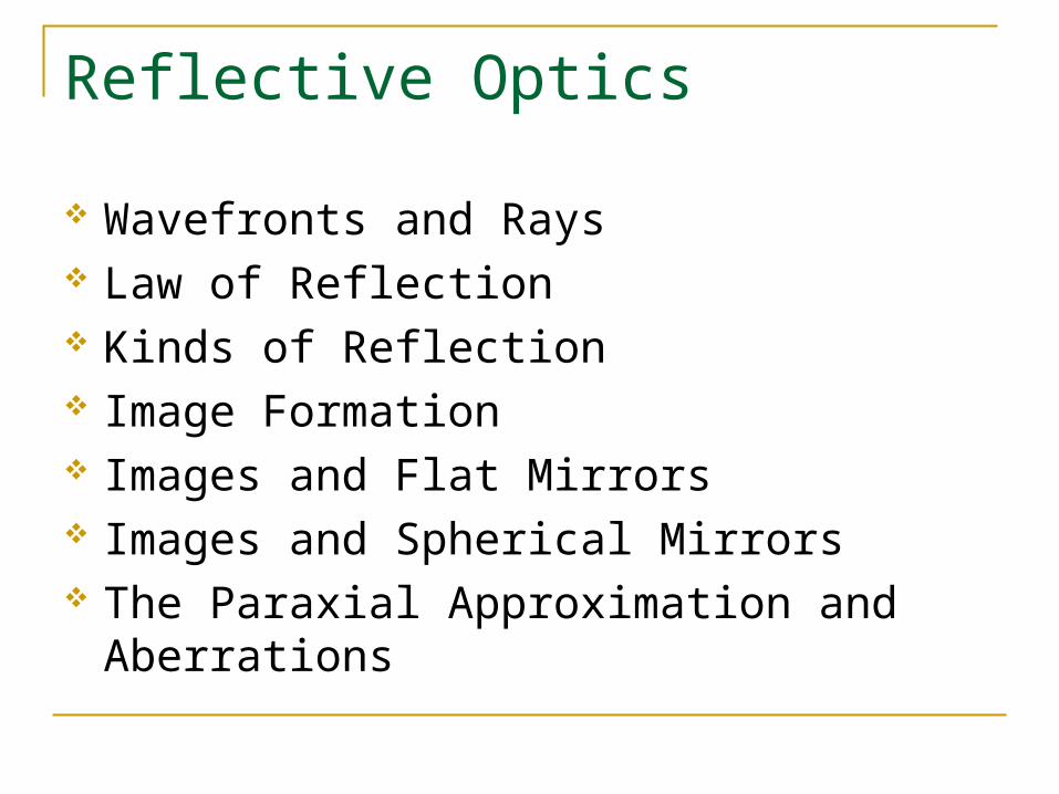
A wave is the propagation of a condition or disturbance.
A wavefront is a surface over which the value of that condition is constant.
wavef ronts(E = E0)
ray
ray
ray
ray
Wavefronts and Rays
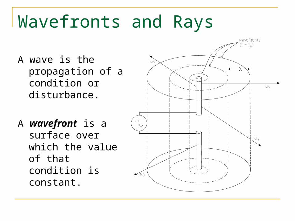
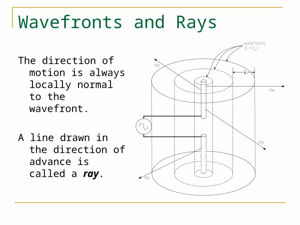
The direction of motion is always locally normal to the wavefront.
A line drawn in the direction of advance is called a ray.
wavef ronts(E = E0)
ray
ray
ray
ray
Wavefronts and Rays
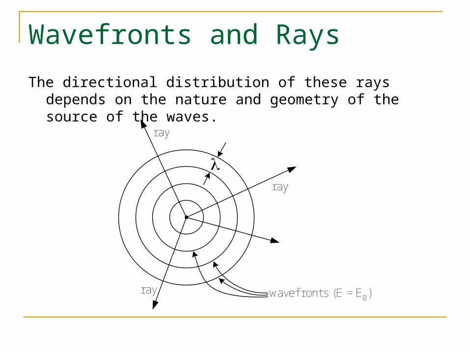
The directional distribution of these rays depends on the nature and geometry of the source of the waves.
wavef ronts (E = E0)
ray
ray
ray
Wavefronts and Rays
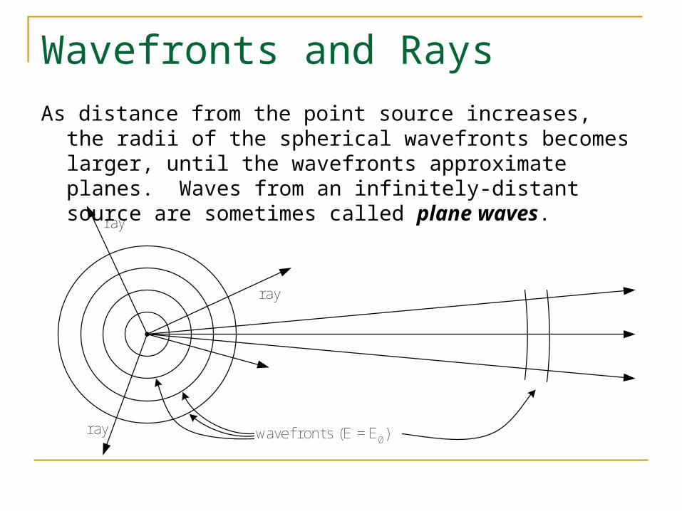
As distance from the point source increases, the radii of the spherical wavefronts becomes larger, until the wavefronts approximate planes. Waves from an infinitely-distant source are sometimes called plane waves.
wavef ronts (E = E0)
ray
ray
ray
Law of Reflection
When light encounters the surface of a material, three things happen:
reflection
transmission
absorption
Law of Reflection
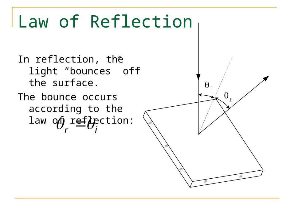
In reflection, the light “bounces” off the surface.
The bounce occurs according to the law of reflection:
ir
ir
Law of Reflection
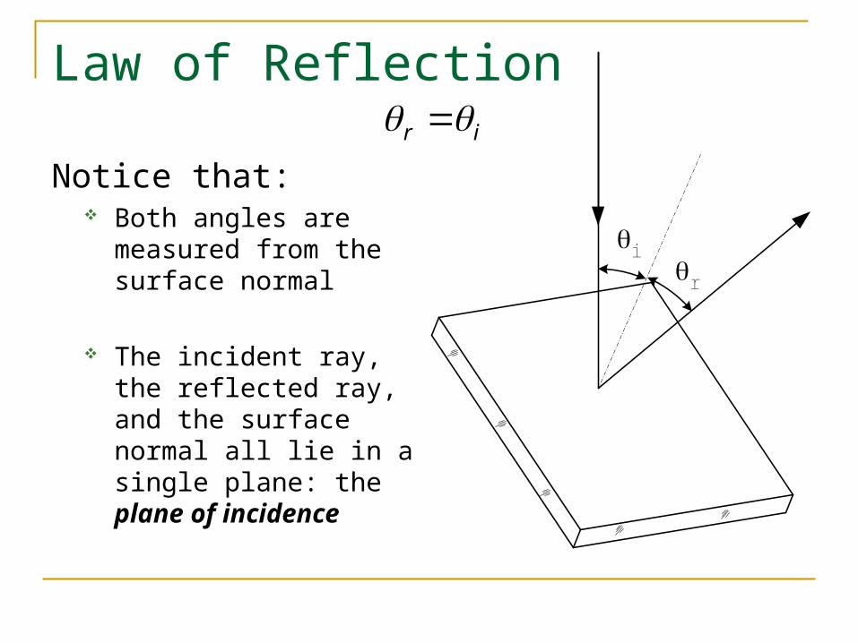
Notice that: Both angles are measured
from the surface normal
The incident ray, the reflected ray, and the surface normal all lie in a single plane: the plane of incidence
ir
ir
Law of Reflection
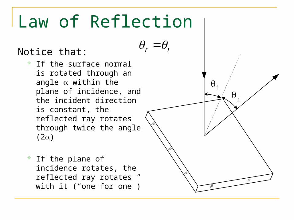
Notice that: If the surface normal is
rotated through an angle within the plane of incidence, and the incident direction is constant, the reflected ray rotates through twice the angle (2)
If the plane of incidence rotates, the reflected ray rotates with it (“one for one”)
ir
ir
Kinds of Reflection
We distinguish between two sorts of reflection: Specular (from smooth surfaces)
mirror polished metal calm liquid
Diffuse (from rough or irregular surfaces) white paper projection screen clouds or snow
Kinds of Reflection: Specular
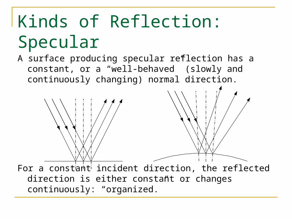
A surface producing specular reflection has a constant, or a “well-behaved” (slowly and continuously changing) normal direction.
For a constant incident direction, the reflected direction is either constant or changes continuously: “organized.”
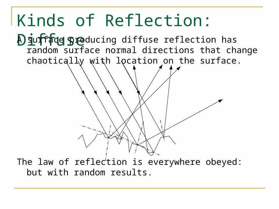
Kinds of Reflection: DiffuseA surface producing diffuse reflection has random surface
normal directions that change chaotically with location on the surface.
The law of reflection is everywhere obeyed: but with random results.
Image Formation
Consider an object that either produces light, or that scatters light from its surroundings. Each point on its surface acts as a spherically-symmetric source (“point source”), sending out rays in many directions.
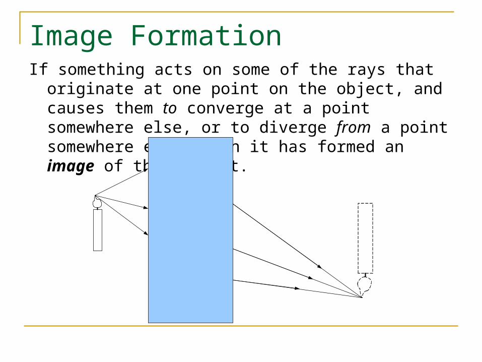
Image FormationIf something acts on some of the rays that originate at one point
on the object, and causes them to converge at a point somewhere else, or to diverge from a point somewhere else, then it has formed an image of that object.
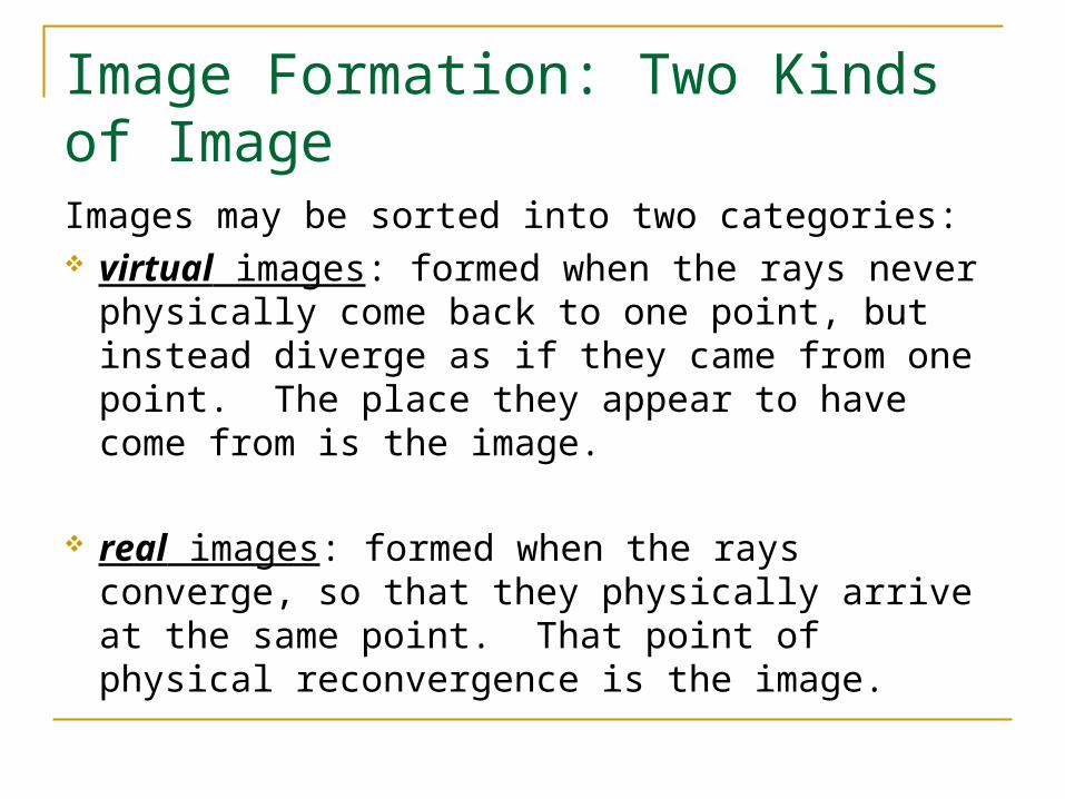
Image Formation: Two Kinds of Image
Images may be sorted into two categories: virtual images: formed when the rays never
physically come back to one point, but instead diverge as if they came from one point. The place they appear to have come from is the image.
real images: formed when the rays converge, so that they physically arrive at the same point. That point of physical reconvergence is the image.
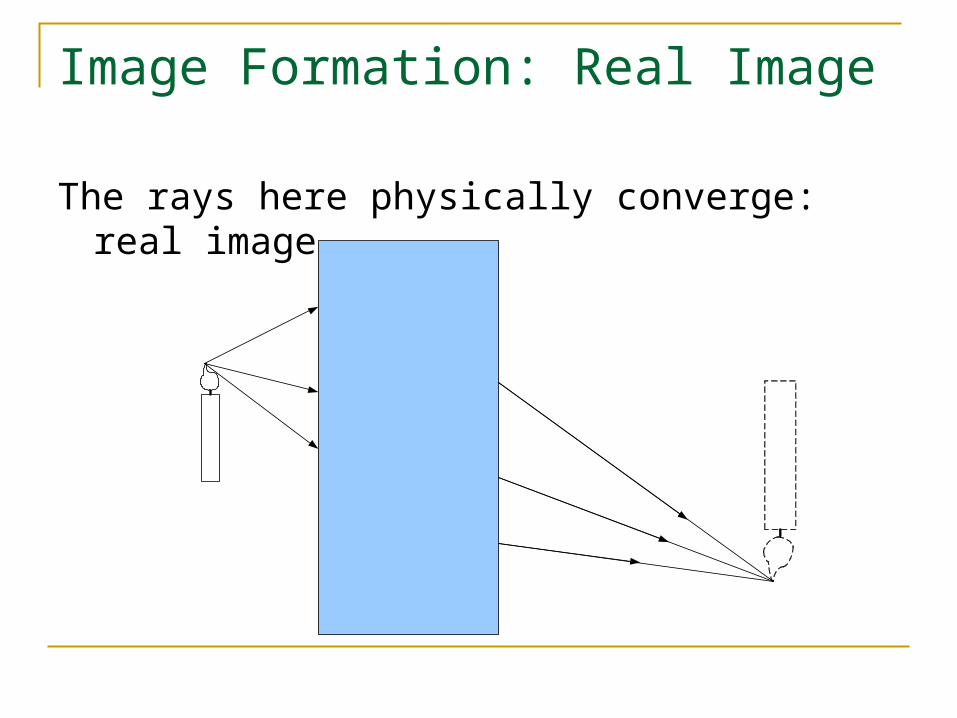
Image Formation: Real Image
The rays here physically converge: real image.
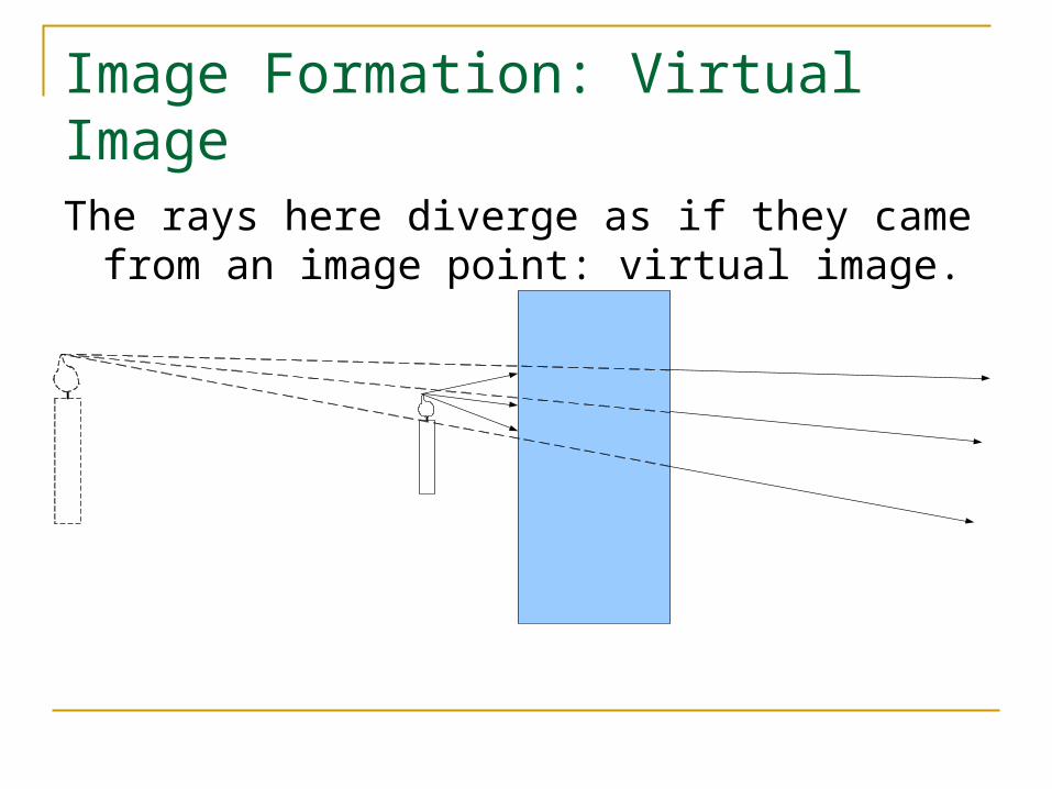
Image Formation: Virtual Image
The rays here diverge as if they came from an image point: virtual image.
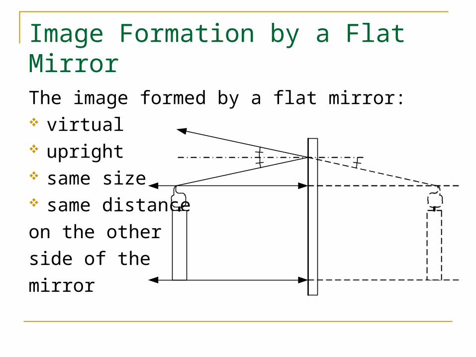
Image Formation by a Flat Mirror
The image formed by a flat mirror: virtual upright same size same distance
on the other
side of the
mirror
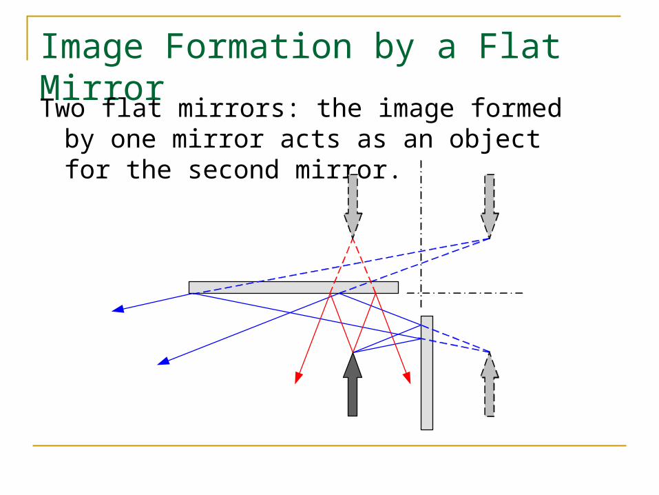
Image Formation by a Flat Mirror
Two flat mirrors: the image formed by one mirror acts as an object for the second mirror.
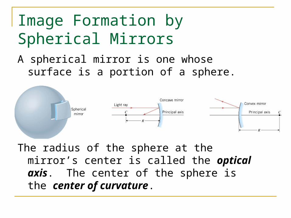
Image Formation by Spherical Mirrors
A spherical mirror is one whose surface is a portion of a sphere.
The radius of the sphere at the mirror’s center is called the optical axis. The center of the sphere is the center of curvature.
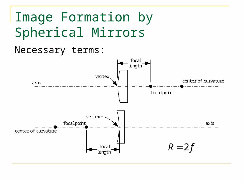
Image Formation by Spherical Mirrors
Necessary terms:
center of curvature
center of curvature
focal point
f ocal point
vertex
vertexaxis
axis
f ocallength
focallength
fR 2
Spherical Mirrors: Special Rays
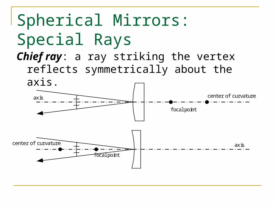
Chief ray: a ray striking the vertex reflects symmetrically about the axis.
center of curvature
center of curvature
f ocal point
f ocal point
axis
axis
Spherical Mirrors: Special Rays
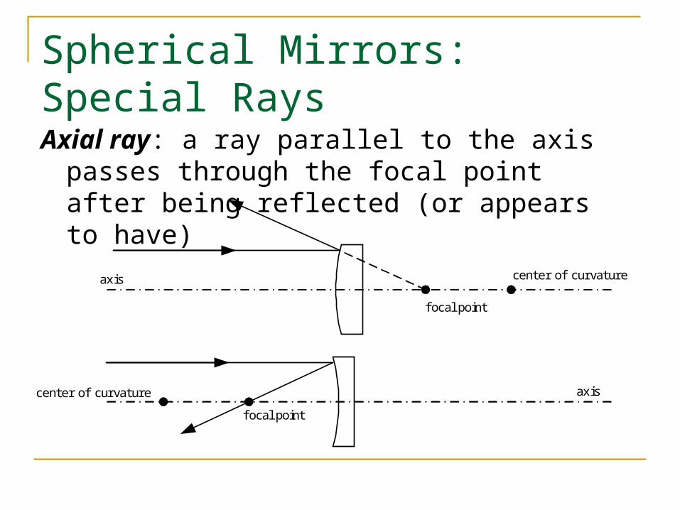
Axial ray: a ray parallel to the axis passes through the focal point after being reflected (or appears to have)
center of curvature
center of curvature
focal point
f ocal point
axis
axis
Spherical Mirrors: Special Rays
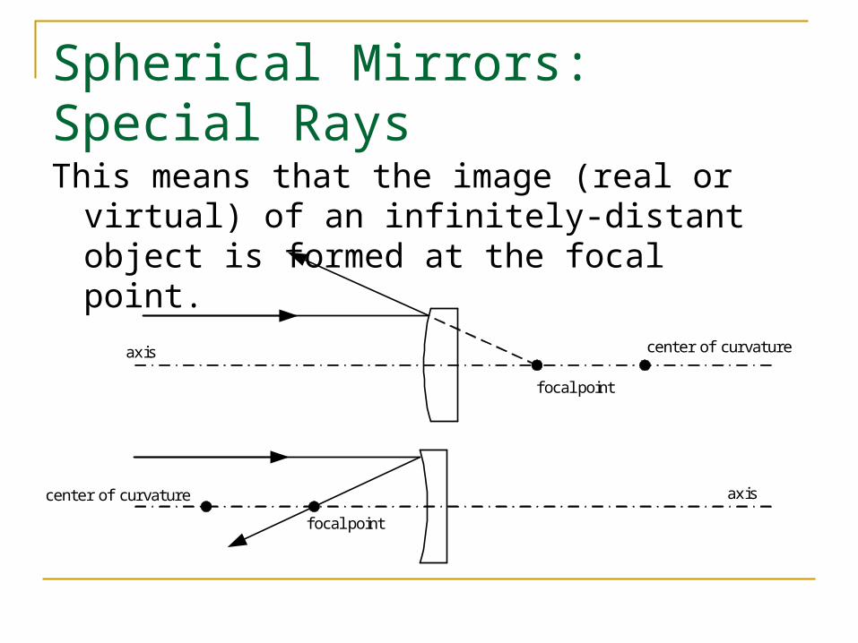
This means that the image (real or virtual) of an infinitely-distant object is formed at the focal point.
center of curvature
center of curvature
focal point
f ocal point
axis
axis
Spherical Mirrors: Special Rays
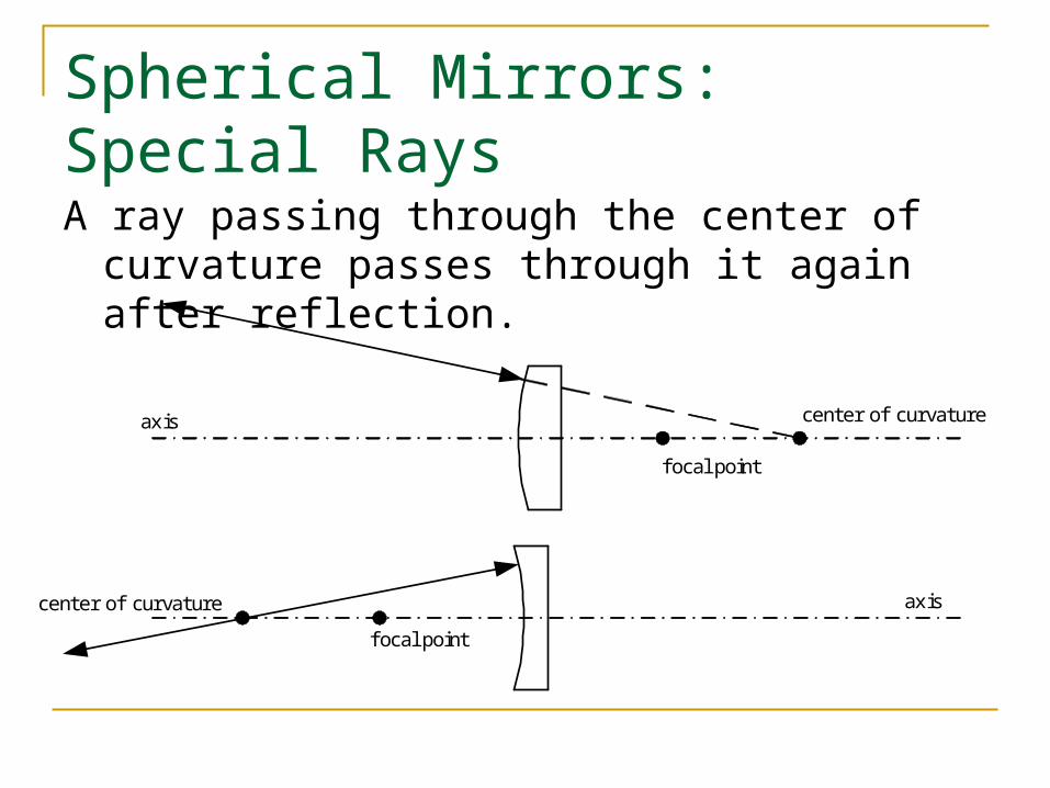
A ray passing through the center of curvature passes through it again after reflection.
center of curvature
center of curvature
focal point
f ocal point
axis
axis
Finding Images by Ray Tracing
We can use these special ray properties to find the locations where images are formed.
We can also find out:
the image size the image orientation whether the image is real or virtual
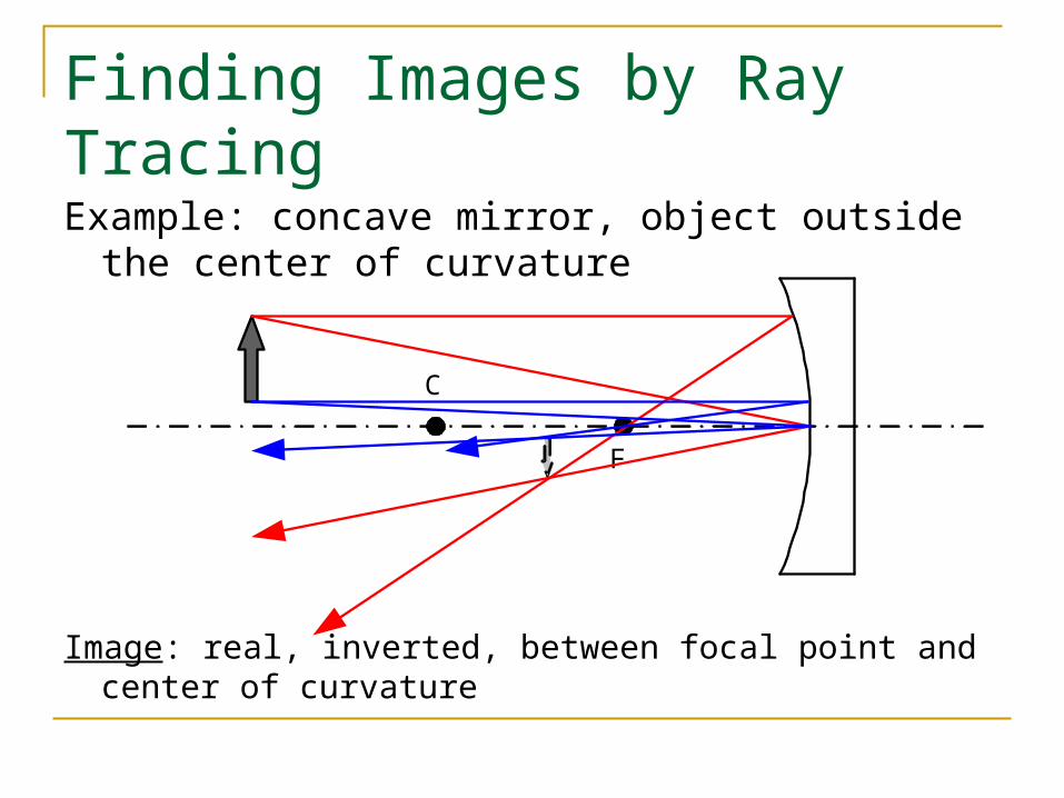
Finding Images by Ray Tracing
Example: concave mirror, object outside the center of curvature
Image: real, inverted, between focal point and center of curvature
C
F
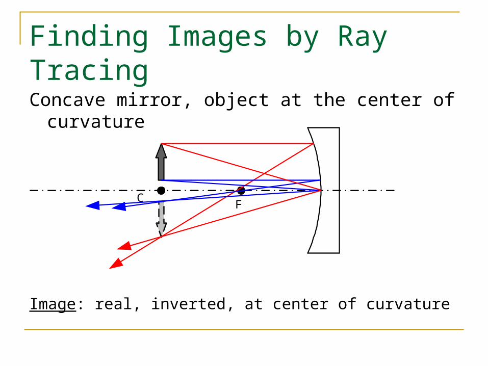
Finding Images by Ray Tracing
Concave mirror, object at the center of curvature
Image: real, inverted, at center of curvature
C F
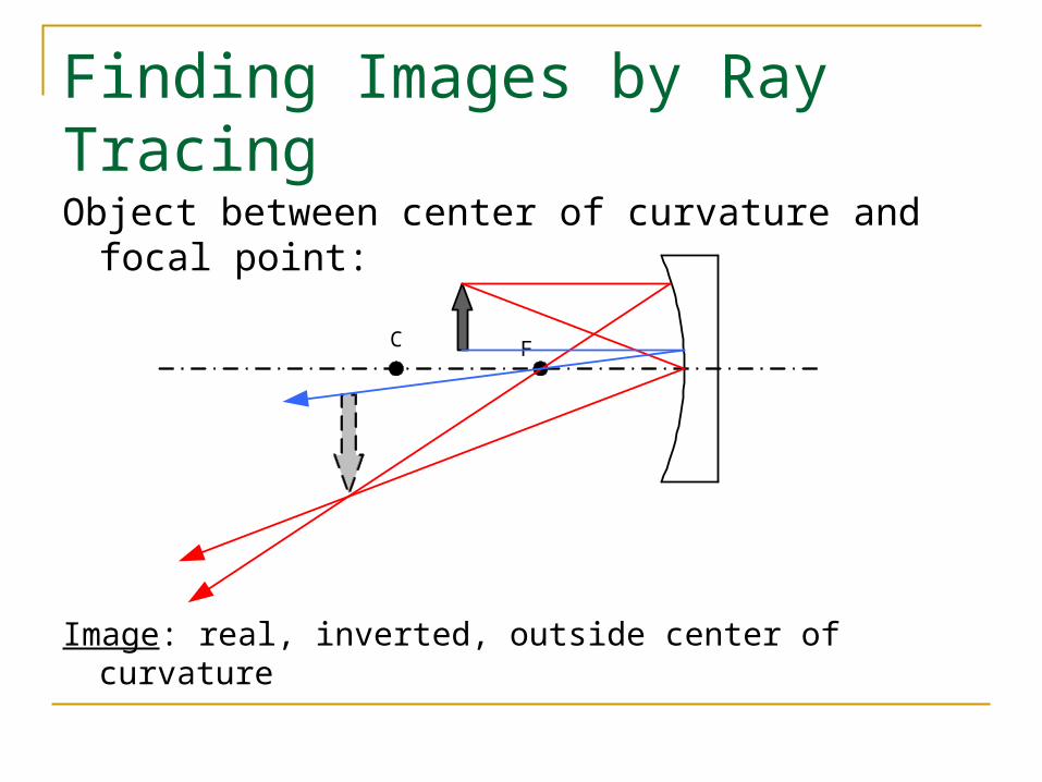
Finding Images by Ray Tracing
Object between center of curvature and focal point:
Image: real, inverted, outside center of curvature
C F
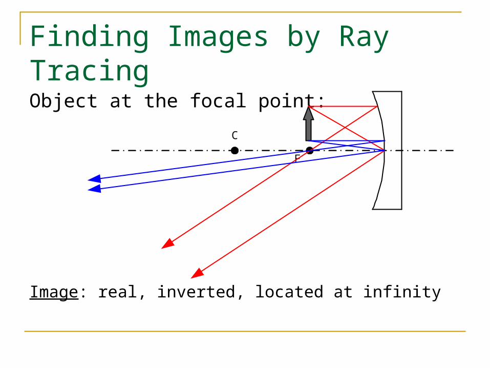
Finding Images by Ray Tracing
Object at the focal point:
Image: real, inverted, located at infinity
C
F
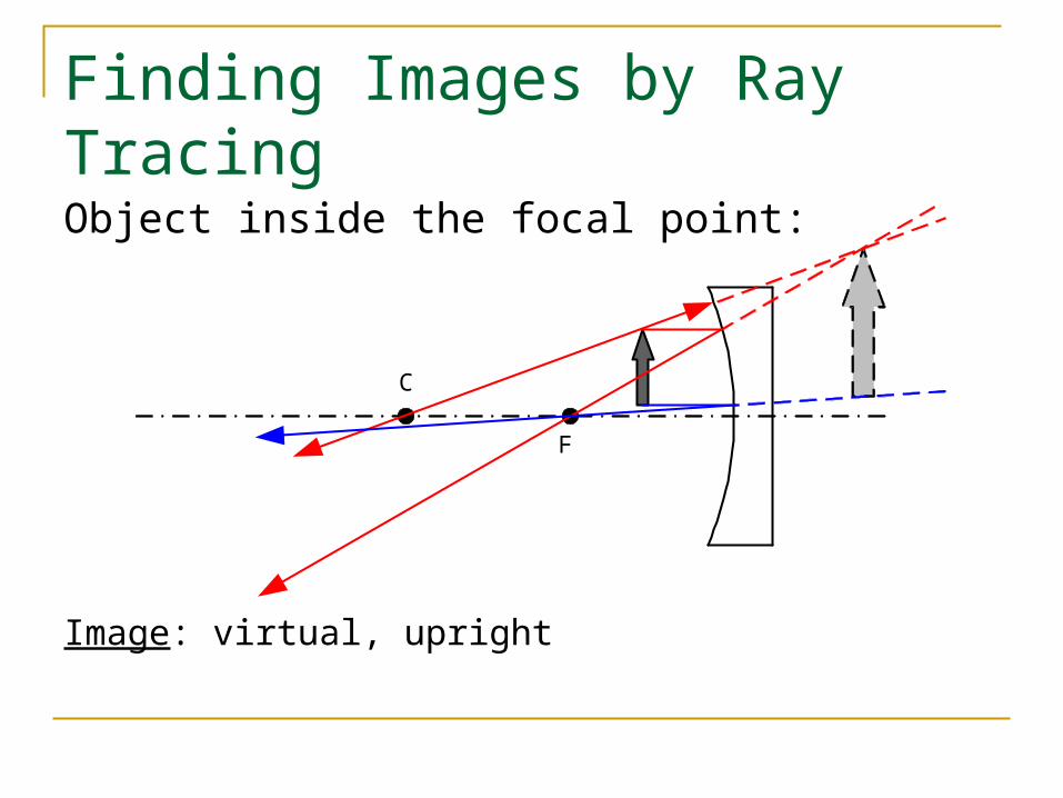
Finding Images by Ray Tracing
Object inside the focal point:
Image: virtual, upright
C
F
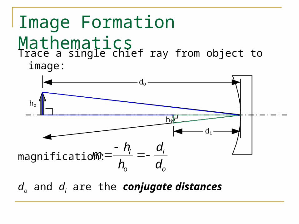
Image Formation Mathematics
Trace a single chief ray from object to image:
magnification:
do and di are the conjugate distances
o
i
o
i
d
d
h
hm
hi
di
do
ho
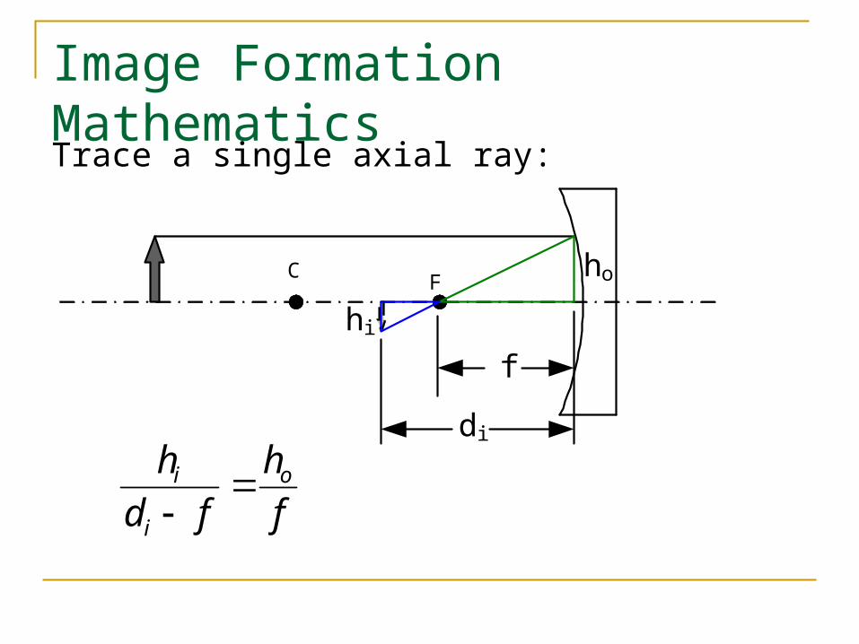
Image Formation Mathematics
Trace a single axial ray:
C Fho
hi
f
di
f
h
fd
h o
i
i
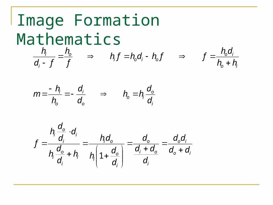
Image Formation Mathematics
io
io
i
oi
o
i
oi
oi
ii
oi
ii
oi
i
oio
o
i
o
i
io
iooioi
o
i
i
dd
dd
d
ddd
d
dh
dh
hd
dh
dd
dh
f
d
dhh
d
d
h
hm
hh
dhffhdhfh
f
h
fd
h
1
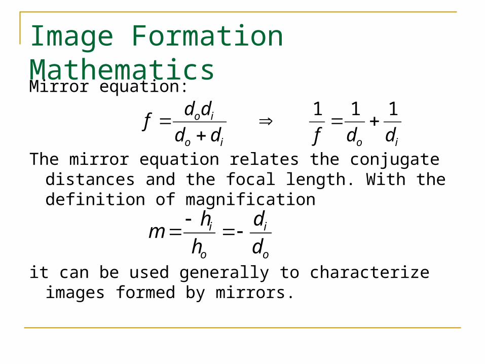
Image Formation Mathematics
Mirror equation:
The mirror equation relates the conjugate distances and the focal length. With the definition of magnification
it can be used generally to characterize images formed by mirrors.
ioio
io
ddfdd
ddf
111
o
i
o
i
d
d
h
hm
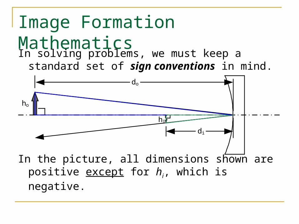
Image Formation Mathematics
In solving problems, we must keep a standard set of sign conventions in mind.
In the picture, all dimensions shown are positive except for hi, which is negative.
hi
di
do
ho
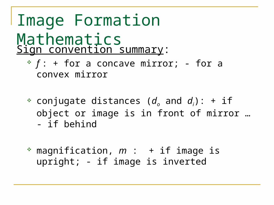
Image Formation Mathematics
Sign convention summary: f : + for a concave mirror; - for a convex mirror
conjugate distances (do and di): + if object or image is in front of mirror … - if behind
magnification, m : + if image is upright; - if image is inverted
The Paraxial Approximation
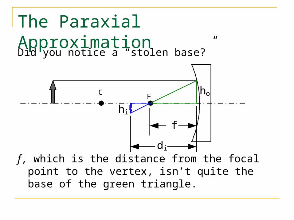
Did you notice a “stolen base?”
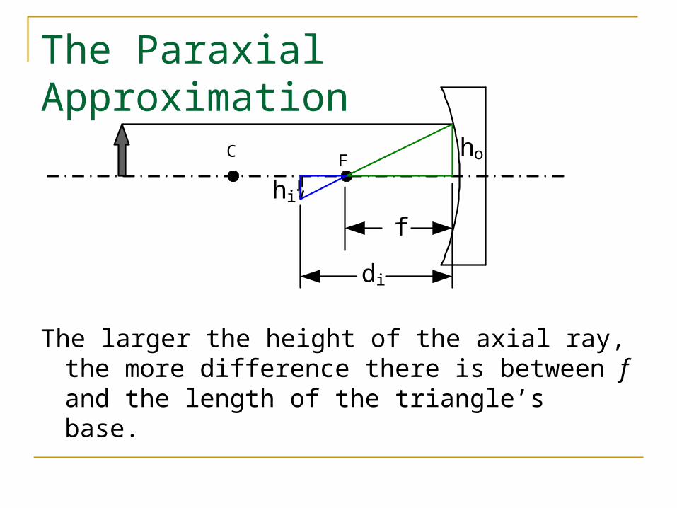
f, which is the distance from the focal point to the vertex, isn’t quite the base of the green triangle.
C Fho
hi
f
di
The Paraxial Approximation
The larger the height of the axial ray, the more difference there is between f and the length of the triangle’s base.
C Fho
hi
f
di
The Paraxial Approximation
The mirror equation is valid only as a paraxial approximation. It applies to a threadlike cylinder of infinitesimal diameter, centered on the axis.
The difference between the paraxial approximation and the consequences of exact spherical geometry cause what is called spherical aberration.
The larger the height of an axial ray, the closer to the vertex it passes through the axis.
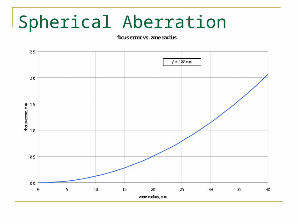
Spherical Aberrationfocus error vs. zone radius
0.0
0.5
1.0
1.5
2.0
2.5
0 5 10 15 20 25 30 35 40
zone radius, mm
focu
s er
ror,
mm
f = 100 mm
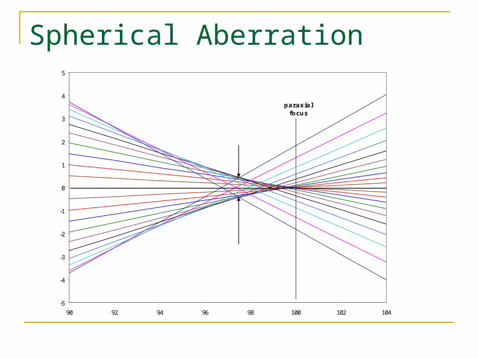
Spherical Aberration
-5
-4
-3
-2
-1
0
1
2
3
4
5
90 92 94 96 98 100 102 104
paraxialfocus
circle ofleast confusion
The Paraxial Approximation
So: what good is the mirror equation, since it is only an approximation?
Optical system design: paraxial layout (approximation) computer modeling and optimization (exact)