Embed Size (px)
Citation preview
QoSMOS D3.4
The research leading to these results was derived from the European Community’s Seventh Framework
Programme (FP7) under Grant Agreement number 248454 (QoSMOS)
Quality Of Service and MObility driven cognitive radio Systems
FP7-ICT-2009-4/248454
QoSMOS
D3.4
Reference Protocol Stack for QoSMOS
Contractual Date of Delivery to the CEC: 31-Mar-2012
Actual Date of Delivery to the CEC: 31-Mar-2012
Editor(s): Rainer Wansch (Fraunhofer IIS)
Author(s): Ulrico Celentano (UOULU), Kazushi Muraoka,
Masayuki Ariyoshi (NEC), Abdoulaye Bagayoko,
Dorin Panaitopol, Philippe Delahaye (NTUK) ,
Xiaobo YU, Piraba Navaratnam, Klaus Moessner
(UNIS), Atilio Gameiro (IT), Ferdinand Kemeth,
Rainer Wansch (Fraunhofer IIS), Dominique Noguet,
Vincent Berg (CEA)
Workpackage: WP3
Est. person months: 28 PM
Security: PU
Nature: R
Version: 1.0
Total number of pages: 56
Abstract:
This deliverable D3.4 aims at the definition of relevant messages for distributing and requesting
sensing measurement information. It takes the requirements imposed by the different entities in the
QoSMOS system model, from the scenarios and existing standards as a basis to define the interfaces
and the needed messages. It is not intended to implement a dedicated protocol stack - instead it as a
generic approach to serve different implementations.
Keyword list:
Cognitive Radio, Spectrum Sensing, Protocol Stack
QoSMOS D3.4
2
Abbreviations
3GPP 3rd
Generation Partnership Project
AACA Adaptive Admission Control Algorithm
ACA Admission Control Algorithm
ACV Admission Control Validation
AL Adaptation Layer
AP Access Point
API Application Programming Interface
APR Arrival Priority
BS Base Station
CDMA Code Division Multiple Access
CE Cognitive Engine
CFP Contention Free Period
CIR Carrier to Interference Ratio
CM Cognitive Manager
CP Contention Period
CTRL ConTRoL
DA Data Archive
DELTS DELete Traffic Session
DEV [network] DEVice
DOP Dilution of Precision
DRX Discontinuous Reception
EDCA Enhanced Distributed Channel Access
EDCA/DRR EDCA with Distributed Resource Reservation
EDCA/RR EDCA with Resource Reservation
eNB e Node B
QoSMOS D3.4
3
E-OTD Enhanced Observed Time Difference
GPS Global Positioning System
GW GateWay
I/F InterFace
IACA Initial Admission Control Algorithm
IEEE Institute of Electrical and Electronics Engineers
IND INDication
IRNSS Indian Regional Navigational Satellite System
LOC LOCalised context
LTE [3GPP] Long Term Evolution
MAC Medium Access Control
MG Measurement Gap
MGT ManaGemenT
MRN Maximum RTTF Number
MSC Message Sequence Chart
NC Networking [domain] Cognition
NRTTF Non-Real Time Traffic Fraction
OSI Open Systems Interconnection
OTDoA Observed Time Difference of Arrival
PF PortFolio repository
REG REGulatory repository
REP REPositories management
REQ REQuest
RF Radio Frequency
RM Resource Management
RRC Radio Resource Control
RSP ReSPonse
QoSMOS D3.4
4
RSSI Received Signal Strength Indicator
RTTF Real Time Traffic Fraction
SAN Spectrum ANalyser
SI Service Interval
SM Spectrum Management
SNR Signal to Noise Ratio
SotA State of the Art
SS Spectrum Sensing
SS MGT Spectrum Sensing ManaGemenT
SS SCTRL Spectrum Sensing Sensor ConTRoL
SSC Centralised Spectrum Sensing
SSD Distributed Spectrum Sensing
SSID Service Set IDentification
SSL Local Spectrum Sensing
TC Terminating (domain) Cognition
TDMA Time Division Multiple Access
ToA Time of Arrival
TRX Transceiver
TTFF Time To First Fix
TVWS TV WhiteSpace
TXOP Transmission Opportunity
UE User Equipment
UERE User Equivalent Range Error
U-TDoA Uplink Time Difference of Arrival
WLAN Wireless Local Area Network
QoSMOS D3.4
5
Table of contents
1 EXECUTIVE SUMMARY .......................................................................................................... 8
2 INTRODUCTION ........................................................................................................................ 9
3 FRAMEWORK FOR RADIO ENVIRONMENT CONTEXT ACQUISITION.................. 10
3.1 SYSTEM MODEL ...................................................................................................................... 10 3.2 FUNCTIONAL ARCHITECTURE AND INTERFACES .................................................................... 13 3.3 RELEVANT MESSAGE SEQUENCE CHARTS .............................................................................. 16
3.3.1 Spectrum Sensing ............................................................................................................... 16 3.3.1.1 Local Spectrum Sensing ............................................................................................ 16 3.3.1.2 Centralised Spectrum Sensing ................................................................................... 16 3.3.1.3 Distributed Spectrum Sensing ................................................................................... 18
3.3.2 Interference Monitoring ..................................................................................................... 20
4 REQUIREMENTS FOR RADIO ENVIRONMENT CONTEXT ACQUISITION
PROTOCOL STACK .......................................................................................................................... 23
4.1 SPECIFICATION AS PROPOSED BY IEEE1900.6 ....................................................................... 23 4.2 OVERVIEW ON SOTA POSITION CONTEXT ACQUISITION TECHNIQUES .................................. 25 4.3 REQUIREMENTS DERIVED FROM QOSMOS SYSTEM REQUIREMENTS .................................... 29 4.4 REQUIREMENTS FROM CM-RM AND CM-SM ........................................................................ 31
4.4.1 Interaction with CM-RM .................................................................................................... 31 4.4.2 Interaction with CM-SM .................................................................................................... 32
4.5 LTE EXTENSION...................................................................................................................... 33 4.5.1 Introduction ....................................................................................................................... 33 4.5.2 Requirements for LTE Extension in TVWS ........................................................................ 33
4.5.2.1 Sensing Measurements Requirements ....................................................................... 35 4.5.2.2 Protocol Stack Performance Requirements for Sensing ............................................ 36 4.5.2.3 Sensing Reporting Requirements .............................................................................. 37
4.5.3 Way Forward ..................................................................................................................... 38 4.6 EXTENSION TO IEEE 802.11 ................................................................................................... 38
4.6.1 Distributed Resource Reservation for 802.11 .................................................................... 38 4.6.2 Distributed Releasing Process ........................................................................................... 39 4.6.3 Distributed Re-Allocating Process .................................................................................... 40 4.6.4 Performance Evaluation .................................................................................................... 40 4.6.5 Requirements Tables .......................................................................................................... 43
5 QOSMOS PROTOCOL STACK MESSAGES ....................................................................... 44
5.1 REFLECTION OF THE REQUIREMENTS ..................................................................................... 44 5.2 INTERFACE MESSAGES ............................................................................................................ 45
5.2.1 Sensing-Transceiver Interface SS2 .................................................................................... 45 5.2.2 Sensing-Resource Manager/Spectrum Manager Interface SS1 ......................................... 46 5.2.3 Spectrum Sensing Management-Spectrum Sensing Sensor Control Interface SS0 ............ 47
5.3 CLASSIFICATION OF THE QOSMOS DATA FIELDS .................................................................. 48
6 APPENDIX ................................................................................................................................. 51
7 REFERENCES ........................................................................................................................... 54
QoSMOS D3.4
6
List of figures
Figure 2-1: Approach for generation of protocol stack messages ............................................................ 9
Figure 3-1: The relevant part for spectrum sensing of the QoSMOS functional architecture ................ 11
Figure 3-2: Centralised, distributed and local spectrum sensing topologies .......................................... 12
Figure 3-3: Reference system model for spectrum sensing .................................................................... 14
Figure 3-4: Messages for local spectrum sensing ................................................................................... 16
Figure 3-5: Centralized spectrum sensing (simplified representation) ................................................... 17
Figure 3-6: Centralized spectrum sensing (complete representation) .................................................... 18
Figure 3-7: Distributed spectrum sensing (simplified representation) ................................................... 19
Figure 3-8: Distributed spectrum sensing (complete representation) ..................................................... 20
Figure 3-9: Interference monitoring concept .......................................................................................... 21
Figure 3-10: Procedures for interference monitoring ............................................................................. 22
Figure 4-1: IEEE 1900.6 interface definition ......................................................................................... 23
Figure 4-2: IEEE 1900.6 interface definition ......................................................................................... 24
Figure 4-3: CM-RM reference model..................................................................................................... 31
Figure 4-4: Spectrum monitoring integration in LTE ............................................................................ 34
Figure 4-5: IACA and AACA Algorithms ............................................................................................. 39
Figure 4-6: EDCA/RR ............................................................................................................................ 41
Figure 4-7: EDCA/DRR ......................................................................................................................... 41
Figure 4-8: Channel Capacity/Usage ..................................................................................................... 42
QoSMOS D3.4
7
List of tables
Table 3-1: External and internal interfaces related to spectrum sensing ................................................ 14
Table 4-1: Overview of positioning methods ......................................................................................... 26
Table 4-2: Example of observed GPS error budget ................................................................................ 27
Table 4-3: Performance characteristics of cellular positioning methods [Küppe05] ............................. 28
Table 4-4: SS1b#2 interface summary ................................................................................................... 31
Table 4-5: SS1b#3 interface summary ................................................................................................... 32
Table 4-6: SS1a primitives and their functions ...................................................................................... 33
Table 4-7: Sensing measurements requirements .................................................................................... 35
Table 4-8: Protocol stack performance requirements for sensing .......................................................... 36
Table 4-9: Sensing report requirements ................................................................................................. 37
Table 4-10: Simulation parameters ........................................................................................................ 40
Table 4-11: Average throughput in DRR ............................................................................................... 42
Table 4-12: Sensing measurements requirements .................................................................................. 43
Table 4-13: Sensing report requirements ............................................................................................... 43
Table 5-1: Relationship between QoSMOS protocol stack solution and related requirements ............. 44
Table 5-2: Data fields of the Sensing-Transceiver Interface SS2 .......................................................... 45
Table 5-3: Data fields of the Sensing-Resource Manager/Spectrum Manager Interface SS1 ................ 46
Table 5-4: Data fields of the Spectrum Sensing Management-Spectrum Sensing Sensor Control
Interface SS0 .................................................................................................................................. 47
Table 5-5: Structure to describe the data fields needed by QoSMOS .................................................... 48
Table 6-1: Primitives involved in interference monitoring .................................................................... 51
QoSMOS D3.4
8
1 Executive Summary
Deliverable D3.4 sets forth the work started and documented in D3.2 [D3.2]. Whereas D3.2 was more
a common view on the sensing framework, we here focus on the protocol stack messages, the relevant
requirements and how these are linked together.
First, in chapter 3, the system model for spectrum sensing is defined in more detail describing
especially the interfaces between the spectrum sensing and the other building blocks of the system
model. This is first done in a more abstract way to see how the spectrum sensing is involved in the
overall system and giving an overview on the needed interfaces. The different sensing topologies
centralised, distributed and local sensing induce a different partitioning of the building blocks inside
the sensing framework (management and control block) and in the different equipment like user
equipment, base stations and gate ways. A proper distribution of the functions is needed as the sensing
always communicates for the measurement with the transceivers which have different capabilities in
the different equipment. The functional architecture of the spectrum sensing is refined in chapter 3.2
and the interfaces are described with their main functionality. Message sequence charts for the
different sensing topologies and for interference monitoring highlight how the messages for spectrum
sensing are handled within the sensing part of the QoSMOS system.
Chapter 4 deduces and describes requirements from different standards, system blocks and from the
QoSMOS system requirements. It starts with a recapitulation of the proposals from P1900.6 where
interfaces for invoking spectrum sensing in a cognitive system have been defined. This is used as a
baseline. Additionally, requirements from context acquisition in terms of determining the position of
sensor and the different methods are described in the following sub-chapter. It can be shown that all
existing (most of them already implemented in many equipment) fulfil the requirements as they have
been set by regulatory bodies. It is therefore not necessary to introduce new methods here.
The remaining part of this chapter starts with defining requirements for the protocol stack messages
from a QoSMOS system point of view. It takes the QoSMOS system requirements and relates them to
6 main functional ones for the protocol stack which are complexity, flexibility, sensor setting
capability, sensor information distribution, sensor measurement results distribution and sensor
decision results distribution. Next to that the interfaces between the spectrum manager, resource
manager and the spectrum sensing are further defined and the main functions are set. To assure that
the later proposed messages can be used by existing standards, requirement sets from LTE and IEEE
802.11 are introduced.
In section 4.6 the protocol stack messages and data fields are defined in detail. This is first done by
setting a relation between the solution and the requirements. As it has been found that P1900.6 is a
sound basis for the messages and many of the needed messages are already defined. Therefore, we
used a subset of the existing messages and defined the missing messages to have a high flexibility and
to minimize the number of messages needed for the spectrum sensing. In this process, work-packages
2, 4, 5 and 6 were involved to reflect their needs. The different fields are then mapped to the different
interfaces and are defined in Table 5-2, Table 5-3 and Table 5-4. In the final chapter 5.3, the QoSMOS
data fields are grouped in 4 groups: sensor information (SensorInfo), sensor setting (SensorSet),
measurement and sensing result. In Table 5-5 we also established the relationship between the
message fields and the related QoSMOS system requirements.
QoSMOS D3.4
9
2 Introduction
This deliverable deals with the protocol stack for QoSMOS. It sets forth the results described in
deliverable [D3.2] in which the framework for sensing and the relevant building blocks have been
introduced. Within this document the framework for radio context acquisition is further refined and
the relevant message sequence charts for the different sensing topologies and interference monitoring
are introduced in chapter 3. The structural architecture and the relevant interfaces are described which
relate to the Cognitive Manager for Resource Management (CM-RM), the Cognitive Manager for
Spectrum Management (CM-SM), the Transceiver (TRX) and the sensing blocks.
Chapter 4 describes the requirements set by different standards – like IEEE P1900.6, LTE, and IEEE
802.11 – and by the relevant functional blocks of the QoSMOS architecture. These requirements are
the basis for the generation of the messages inside the QoSMOS protocol stack. To see how these
requirements are reflected in the messages each message will be cross-referenced to the relevant
requirement in chapter 4.6. The messages are defined for the relevant interfaces.
Flexibility is one of the most important requirements for the QoSMOS protocol stack. To cover this,
the focus is on the definition of the messages as they can be transported through the different
standards. With this, we can achieve an implementation in the most flexible way – leading to an
implementation in the overall QoSMOS system approach.
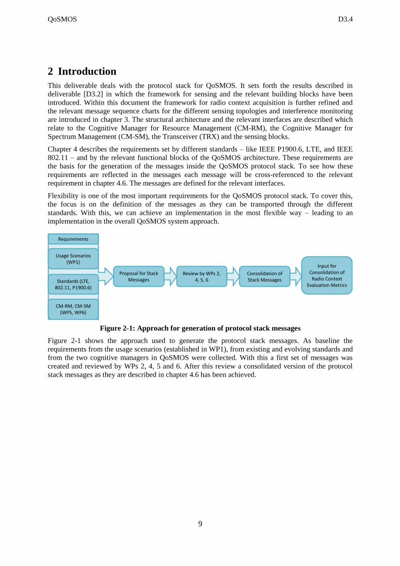
Figure 2-1: Approach for generation of protocol stack messages
Figure 2-1 shows the approach used to generate the protocol stack messages. As baseline the
requirements from the usage scenarios (established in WP1), from existing and evolving standards and
from the two cognitive managers in QoSMOS were collected. With this a first set of messages was
created and reviewed by WPs 2, 4, 5 and 6. After this review a consolidated version of the protocol
stack messages as they are described in chapter 4.6 has been achieved.
Usage Scenarios (WP1)
Standards (LTE, 802.11, P1900.6)
Requirements
CM-RM, CM-SM (WP5, WP6)
Proposal for StackMessages
Review by WPs 2, 4, 5, 6
Consolidation ofStack Messages
Input forConsolidation of
Radio ContextEvaluation Metrics
QoSMOS D3.4
10
3 Framework for Radio Environment Context Acquisition
The scope of the work reported with this document is to identify and present a framework for
spectrum sensing, which includes the architecture with its functional blocks and interfaces.
Radio context may more generally include performance metrics such as other forms of measurements
provided by the lower layers at the transceiver to higher layer blocks (e.g., CM-RM). This deliverable
focuses on measurements peculiar to cognitive radio systems and in particular spectrum sensing and
interference monitoring.
Section 3.1 describes the functional architecture used for the acquisition of the above radio
environment context, section 3.2 discusses the interfaces involved and finally section 3.3 illustrates the
use of the functional blocks and the interfaces with the aid of Message Sequence Charts (MSC).
3.1 System Model
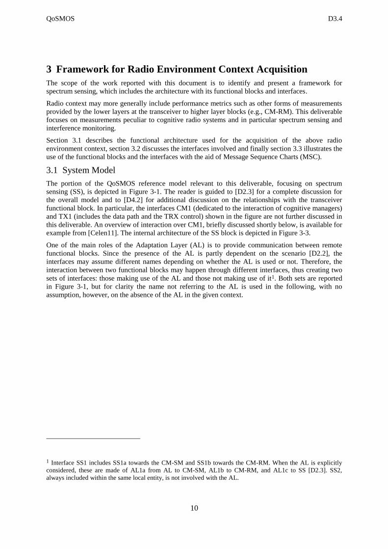
The portion of the QoSMOS reference model relevant to this deliverable, focusing on spectrum
sensing (SS), is depicted in Figure 3-1. The reader is guided to [D2.3] for a complete discussion for
the overall model and to [D4.2] for additional discussion on the relationships with the transceiver
functional block. In particular, the interfaces CM1 (dedicated to the interaction of cognitive managers)
and TX1 (includes the data path and the TRX control) shown in the figure are not further discussed in
this deliverable. An overview of interaction over CM1, briefly discussed shortly below, is available for
example from [Celen11]. The internal architecture of the SS block is depicted in Figure 3-3.
One of the main roles of the Adaptation Layer (AL) is to provide communication between remote
functional blocks. Since the presence of the AL is partly dependent on the scenario [D2.2], the
interfaces may assume different names depending on whether the AL is used or not. Therefore, the
interaction between two functional blocks may happen through different interfaces, thus creating two
sets of interfaces: those making use of the AL and those not making use of it1. Both sets are reported
in Figure 3-1, but for clarity the name not referring to the AL is used in the following, with no
assumption, however, on the absence of the AL in the given context.
1 Interface SS1 includes SS1a towards the CM-SM and SS1b towards the CM-RM. When the AL is explicitly
considered, these are made of AL1a from AL to CM-SM, AL1b to CM-RM, and AL1c to SS [D2.3]. SS2,
always included within the same local entity, is not involved with the AL.
QoSMOS D3.4
11
Figure 3-1: The relevant part for spectrum sensing of the QoSMOS functional
architecture
The CM-SM is responsible for accessing the relevant repositories to generate a spectrum portfolio of
available opportunities. The information may include results of spectrum sensing decisions provided
by the SS. The CM-RM is responsible for providing service to the upper layers, up to the application
and, to this end; it gets the spectrum portfolio deployed by the CM-SM [Celen11]. The CM-RM has
the duty of efficiently managing the spectrum resources; in addition, it is responsible of protection of
incumbent and therefore it may need spectrum sensing decisions from the SS [Mange11].
Whether the use of repositories such as databases or sensing measurements is mandatory or optional
depends on the operating conditions and in particular on the applicable regulatory regime.
In order to avoid path duplicity, sensing decisions are delivered by the SS through a single interface
SS1 (AL1c) towards the AL, which is responsible of the delivery of messages between itself and the
CM-SM and CM-RM.
The main emphasis in this report is on SS1 and SS2 external interfaces, together with the internal SS0,
see also Table 3-1 discussed later. It is worth mentioning that radio environment context acquisition,
in its more general meaning, happens also over TX1. In fact, the CM-RM uses physical layer
measurements provided by the TRX to support the quality of service it has to deliver [D2.2] [D6.2].
The SS gathers the raw sensing measurements from the TRX (and therein from the RF) through the
interface SS2. Spectrum sensing measurements are controlled by the Sensor ConTRoL (SS SCTRL)
functional block. The SS SCTRL, one or more entities of it depending on the sensing topology used
[D3.2], passes those measurements to the ManaGemenT (SS MGT) functional block2, which is in
charge of delivering the spectrum sensing decisions to the functional blocks in need of them. Along
the interfaces SS1 and SS2 flow also the messages about constraints, capabilities and configuration
related to sensing.
2 To this end, the SS MGT includes a multi-sensor processing unit.
QoSMOS D3.4
12
The reason for the split between SS SCTRL and SS MGT is mainly for easing mapping the functional
blocks depending on the topology [D3.2], and this is done by exploiting the so-called topological
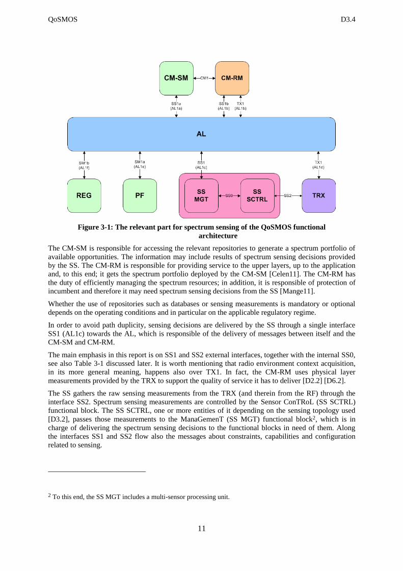
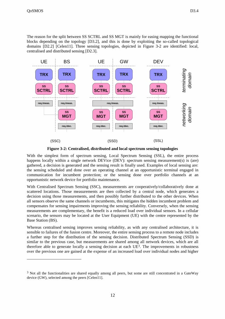
domains [D2.2] [Celen11]. Three sensing topologies, depicted in Figure 3-2 are identified: local,
centralised and distributed sensing [D2.3].
Figure 3-2: Centralised, distributed and local spectrum sensing topologies
With the simplest form of spectrum sensing, Local Spectrum Sensing (SSL), the entire process
happens locally within a single network DEVice (DEV): spectrum sensing measurement(s) is (are)
gathered, a decision is generated and the sensing result is finally used. Examples of local sensing are:
the sensing scheduled and done over an operating channel at an opportunistic terminal engaged in
communication for incumbent protection; or the sensing done over portfolio channels at an
opportunistic network device for portfolio maintenance.
With Centralised Spectrum Sensing (SSC), measurements are cooperatively/collaboratively done at
scattered locations. Those measurements are then collected by a central node, which generates a
decision using those measurements, and then possibly further distributed to the other devices. When
all sensors observe the same channels or incumbents, this mitigates the hidden incumbent problem and
compensates for sensing impairments improving the sensing reliability. Conversely, when the sensing
measurements are complementary, the benefit is a reduced load over individual sensors. In a cellular
scenario, the sensors may be located at the User Equipment (UE) with the centre represented by the
Base Station (BS).
Whereas centralised sensing improves sensing reliability, as with any centralised architecture, it is
sensible to failures of the fusion centre. Moreover, the entire sensing process to a remote node includes
a further step for the distribution of the sensing decision. Distributed Spectrum Sensing (SSD) is
similar to the previous case, but measurements are shared among all network devices, which are all
therefore able to generate locally a sensing decision at each UE3. The improvements in robustness
over the previous one are gained at the expense of an increased load over individual nodes and higher
3 Not all the functionalities are shared equally among all peers, but some are still concentrated in a GateWay
device (GW), selected among the peers [Celen11].
SS
MGT
SS
SCTRL
UE BS
SS
SCTRL
TRX TRX
req./meas. req./meas.
req./dec.
SS
MGT
SS
SCTRL
UE GW
SS
SCTRL
TRX TRX
req./meas.
req./dec.
SS
MGT
req./dec.
SS
MGT
DEV
SS
SCTRL
TRX
req./meas.
req./dec.
(SSC) (SSD) (SSL)
ne
two
rkin
g
do
ma
in
term
ina
tin
g
do
ma
in

QoSMOS D3.4
13
complexity demands for them. For the reasons above, a distributed architecture may be preferred in
some cases, and especially when a distributed architecture is already in place for resource management
and all peers need the availability of a sensing decision [D2.3]. The above topologies impact on the
mapping of spectrum sensing topologies onto the network devices. In case of SSC, measurements are
needed from scattered locations. The measurements provided by those SS SCTRL blocks at
terminating domain are then collected at a central node, such a fusion centre, being therefore in the
networking domain, where the SS MGT resides. However, in case of local sensing, and also in the
case of distributed sensing, even with some differences, the SS SCTRL and SS MGT are co-located at
the same network node, but still residing in their respective domain.
The sensing protocol stack must support all the diverse target scenarios [MacKe11] in the most
flexible way [D1.4]. The comparison of the above sensing topologies is described in Figure 3-2. The
corresponding message sequence charts are described in Sect. 3.3.
Figure 3-3 shows the interfaces relevant to spectrum sensing. Depending on whether the AL is
explicitly considered in the definition of the interfaces, different naming applies (see also Figure 3-1
and the related text). The names used in Figure 3-3 are not referring explicitly to the role of the AL.
The sensing result delivery latency includes the sensing duration, the exchange of commands and
results (including to /from all involved remote sensors, if applicable), the processing of the decision
(e.g., at the centre when applicable), and the distribution of the decision to the requesting entity. The
sensing result delivery latency may possibly be used by the SS to select and tune the sensing method
and algorithm. Depending on the sensing method and algorithm, a sensing reliability is associated.
This can be expressed by probability of detection, probability of false alarm, or other derived metrics.
Of course, there may be trade-offs between sensing delivery latency and reliability. Therefore, these
quantities are used by the SS during the negotiation with the requesting functional block (see for
example [D5.2]).
3.2 Functional Architecture and Interfaces
To further define the interfaces in the spectrum sensing framework, Figure 3-3, we use a slightly
updated spectrum sensing reference model as it was introduced in [D3.2]. One of the main changes is
the interface SS0, which is actually twofold. It serves as interface between the SS MGT and the SS
SCTRL, regardless if they are located within the same unit or if they are distributed among different
units. As mentioned before, the model is introduced in a way that the interfaces are designated with
two names to highlight that they can use the AL or not. For the further definition we will stick with the
AL free designation.
QoSMOS D3.4
14
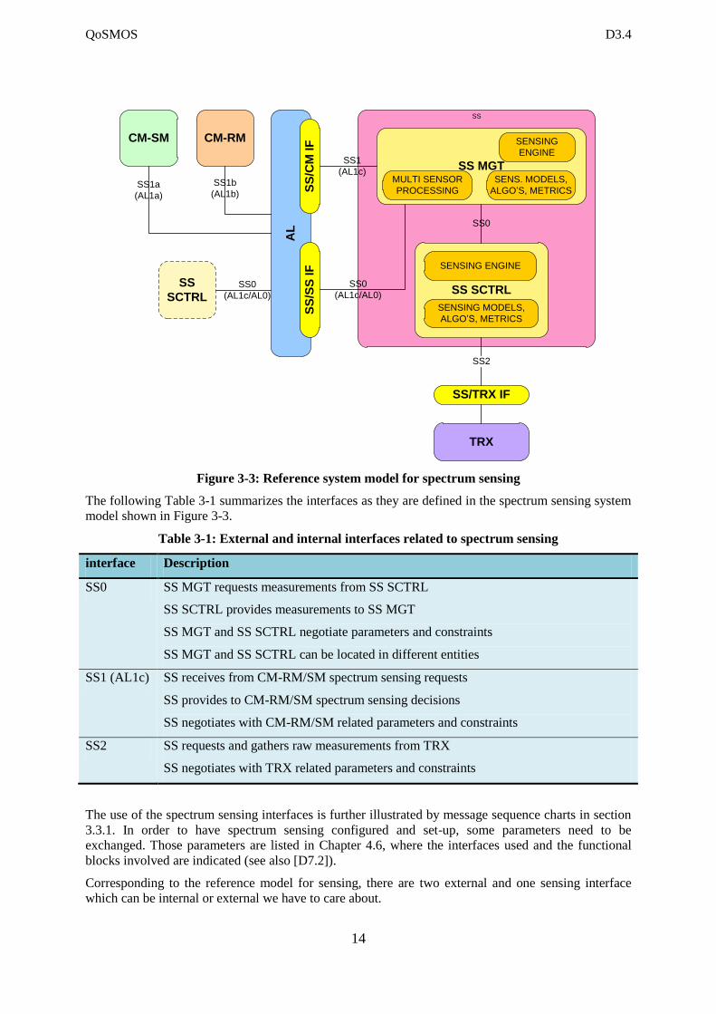
Figure 3-3: Reference system model for spectrum sensing
The following Table 3-1 summarizes the interfaces as they are defined in the spectrum sensing system
model shown in Figure 3-3.
Table 3-1: External and internal interfaces related to spectrum sensing
interface Description
SS0 SS MGT requests measurements from SS SCTRL
SS SCTRL provides measurements to SS MGT
SS MGT and SS SCTRL negotiate parameters and constraints
SS MGT and SS SCTRL can be located in different entities
SS1 (AL1c) SS receives from CM-RM/SM spectrum sensing requests
SS provides to CM-RM/SM spectrum sensing decisions
SS negotiates with CM-RM/SM related parameters and constraints
SS2 SS requests and gathers raw measurements from TRX
SS negotiates with TRX related parameters and constraints
The use of the spectrum sensing interfaces is further illustrated by message sequence charts in section
3.3.1. In order to have spectrum sensing configured and set-up, some parameters need to be
exchanged. Those parameters are listed in Chapter 4.6, where the interfaces used and the functional
blocks involved are indicated (see also [D7.2]).
Corresponding to the reference model for sensing, there are two external and one sensing interface
which can be internal or external we have to care about.
AL
SS
CM-SM CM-RM
TRX
SS/TRX IF
SS SCTRL
SS MGTMULTI SENSOR
PROCESSING
SS
/SS
IF
SENSING
ENGINE
SS0
SS0
(AL1c/AL0)
SS2
SENS. MODELS,
ALGO’S, METRICS
SS1
(AL1c)
SS
/CM
IF
SENSING ENGINE
SENSING MODELS,
ALGO’S, METRICS
SS1a
(AL1a)
SS1b
(AL1b)
SS0
(AL1c/AL0)
SS
SCTRL
QoSMOS D3.4
15
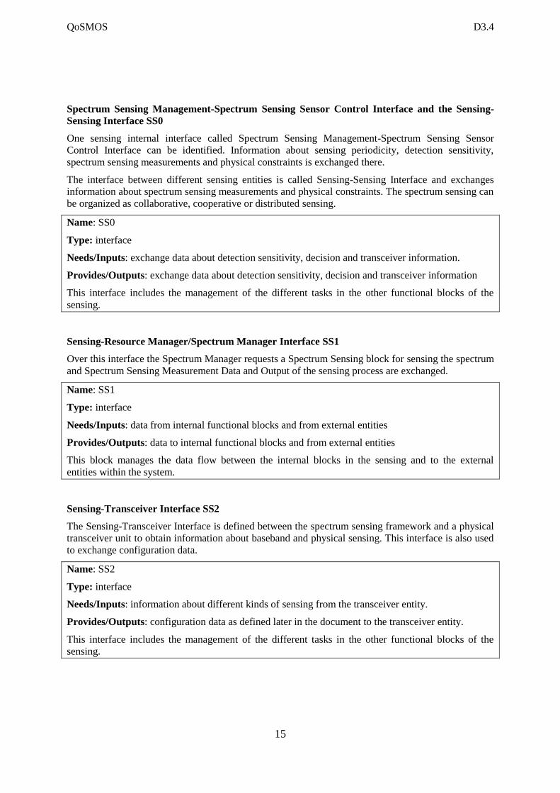
Spectrum Sensing Management-Spectrum Sensing Sensor Control Interface and the Sensing-
Sensing Interface SS0
One sensing internal interface called Spectrum Sensing Management-Spectrum Sensing Sensor
Control Interface can be identified. Information about sensing periodicity, detection sensitivity,
spectrum sensing measurements and physical constraints is exchanged there.
The interface between different sensing entities is called Sensing-Sensing Interface and exchanges
information about spectrum sensing measurements and physical constraints. The spectrum sensing can
be organized as collaborative, cooperative or distributed sensing.
Name: SS0
Type: interface
Needs/Inputs: exchange data about detection sensitivity, decision and transceiver information.
Provides/Outputs: exchange data about detection sensitivity, decision and transceiver information
This interface includes the management of the different tasks in the other functional blocks of the
sensing.
Sensing-Resource Manager/Spectrum Manager Interface SS1
Over this interface the Spectrum Manager requests a Spectrum Sensing block for sensing the spectrum
and Spectrum Sensing Measurement Data and Output of the sensing process are exchanged.
Name: SS1
Type: interface
Needs/Inputs: data from internal functional blocks and from external entities
Provides/Outputs: data to internal functional blocks and from external entities
This block manages the data flow between the internal blocks in the sensing and to the external
entities within the system.
Sensing-Transceiver Interface SS2
The Sensing-Transceiver Interface is defined between the spectrum sensing framework and a physical
transceiver unit to obtain information about baseband and physical sensing. This interface is also used
to exchange configuration data.
Name: SS2
Type: interface
Needs/Inputs: information about different kinds of sensing from the transceiver entity.
Provides/Outputs: configuration data as defined later in the document to the transceiver entity.
This interface includes the management of the different tasks in the other functional blocks of the
sensing.
QoSMOS D3.4
16
3.3 Relevant Message Sequence Charts
3.3.1 Spectrum Sensing
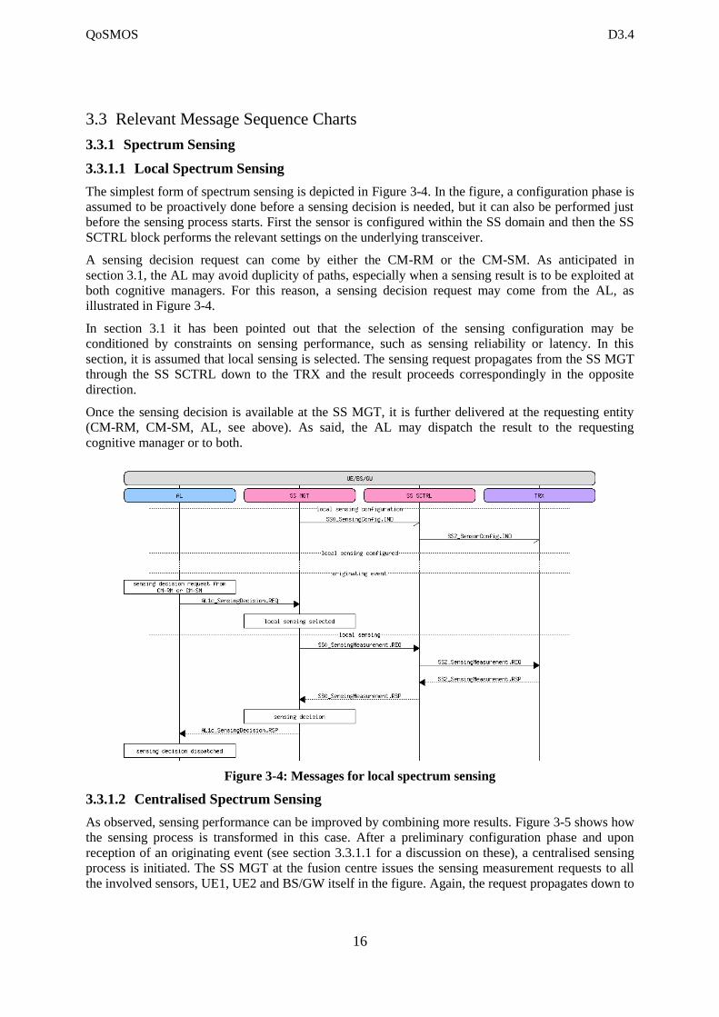
3.3.1.1 Local Spectrum Sensing
The simplest form of spectrum sensing is depicted in Figure 3-4. In the figure, a configuration phase is
assumed to be proactively done before a sensing decision is needed, but it can also be performed just
before the sensing process starts. First the sensor is configured within the SS domain and then the SS
SCTRL block performs the relevant settings on the underlying transceiver.
A sensing decision request can come by either the CM-RM or the CM-SM. As anticipated in
section 3.1, the AL may avoid duplicity of paths, especially when a sensing result is to be exploited at
both cognitive managers. For this reason, a sensing decision request may come from the AL, as
illustrated in Figure 3-4.
In section 3.1 it has been pointed out that the selection of the sensing configuration may be
conditioned by constraints on sensing performance, such as sensing reliability or latency. In this
section, it is assumed that local sensing is selected. The sensing request propagates from the SS MGT
through the SS SCTRL down to the TRX and the result proceeds correspondingly in the opposite
direction.
Once the sensing decision is available at the SS MGT, it is further delivered at the requesting entity
(CM-RM, CM-SM, AL, see above). As said, the AL may dispatch the result to the requesting
cognitive manager or to both.
Figure 3-4: Messages for local spectrum sensing
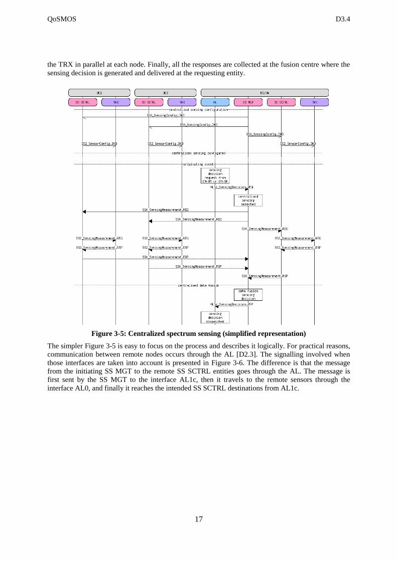
3.3.1.2 Centralised Spectrum Sensing
As observed, sensing performance can be improved by combining more results. Figure 3-5 shows how
the sensing process is transformed in this case. After a preliminary configuration phase and upon
reception of an originating event (see section 3.3.1.1 for a discussion on these), a centralised sensing
process is initiated. The SS MGT at the fusion centre issues the sensing measurement requests to all
the involved sensors, UE1, UE2 and BS/GW itself in the figure. Again, the request propagates down to
QoSMOS D3.4
17
the TRX in parallel at each node. Finally, all the responses are collected at the fusion centre where the
sensing decision is generated and delivered at the requesting entity.
Figure 3-5: Centralized spectrum sensing (simplified representation)
The simpler Figure 3-5 is easy to focus on the process and describes it logically. For practical reasons,
communication between remote nodes occurs through the AL [D2.3]. The signalling involved when
those interfaces are taken into account is presented in Figure 3-6. The difference is that the message
from the initiating SS MGT to the remote SS SCTRL entities goes through the AL. The message is
first sent by the SS MGT to the interface AL1c, then it travels to the remote sensors through the
interface AL0, and finally it reaches the intended SS SCTRL destinations from AL1c.
QoSMOS D3.4
18
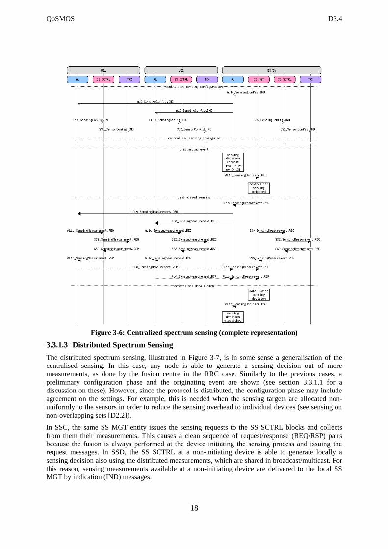
Figure 3-6: Centralized spectrum sensing (complete representation)
3.3.1.3 Distributed Spectrum Sensing
The distributed spectrum sensing, illustrated in Figure 3-7, is in some sense a generalisation of the
centralised sensing. In this case, any node is able to generate a sensing decision out of more
measurements, as done by the fusion centre in the RRC case. Similarly to the previous cases, a
preliminary configuration phase and the originating event are shown (see section 3.3.1.1 for a
discussion on these). However, since the protocol is distributed, the configuration phase may include
agreement on the settings. For example, this is needed when the sensing targets are allocated non-
uniformly to the sensors in order to reduce the sensing overhead to individual devices (see sensing on
non-overlapping sets [D2.2]).
In SSC, the same SS MGT entity issues the sensing requests to the SS SCTRL blocks and collects
from them their measurements. This causes a clean sequence of request/response (REQ/RSP) pairs
because the fusion is always performed at the device initiating the sensing process and issuing the
request messages. In SSD, the SS SCTRL at a non-initiating device is able to generate locally a
sensing decision also using the distributed measurements, which are shared in broadcast/multicast. For
this reason, sensing measurements available at a non-initiating device are delivered to the local SS
MGT by indication (IND) messages.
QoSMOS D3.4
19
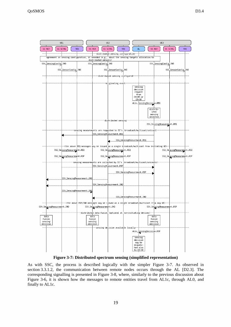
Figure 3-7: Distributed spectrum sensing (simplified representation)
As with SSC, the process is described logically with the simpler Figure 3-7. As observed in
section 3.3.1.2, the communication between remote nodes occurs through the AL [D2.3]. The
corresponding signalling is presented in Figure 3-8, where, similarly to the previous discussion about
Figure 3-6, it is shown how the messages to remote entities travel from AL1c, through AL0, and
finally to AL1c.
QoSMOS D3.4
20
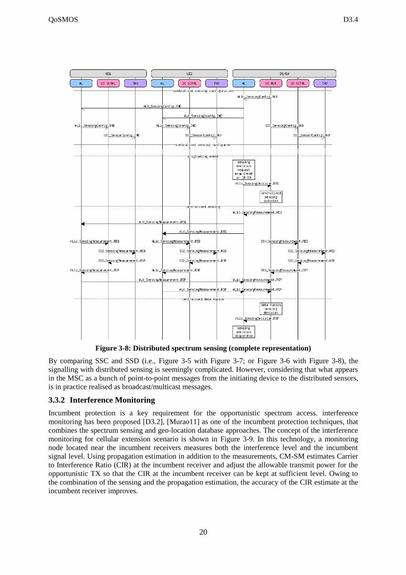
Figure 3-8: Distributed spectrum sensing (complete representation)
By comparing SSC and SSD (i.e., Figure 3-5 with Figure 3-7; or Figure 3-6 with Figure 3-8), the
signalling with distributed sensing is seemingly complicated. However, considering that what appears
in the MSC as a bunch of point-to-point messages from the initiating device to the distributed sensors,
is in practice realised as broadcast/multicast messages.
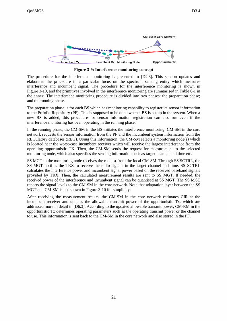
3.3.2 Interference Monitoring
Incumbent protection is a key requirement for the opportunistic spectrum access. interference
monitoring has been proposed [D3.2], [Murao11] as one of the incumbent protection techniques, that
combines the spectrum sensing and geo-location database approaches. The concept of the interference
monitoring for cellular extension scenario is shown in Figure 3-9. In this technology, a monitoring
node located near the incumbent receivers measures both the interference level and the incumbent
signal level. Using propagation estimation in addition to the measurements, CM-SM estimates Carrier
to Interference Ratio (CIR) at the incumbent receiver and adjust the allowable transmit power for the
opportunistic TX so that the CIR at the incumbent receiver can be kept at sufficient level. Owing to
the combination of the sensing and the propagation estimation, the accuracy of the CIR estimate at the
incumbent receiver improves.
QoSMOS D3.4
21
Figure 3-9: Interference monitoring concept
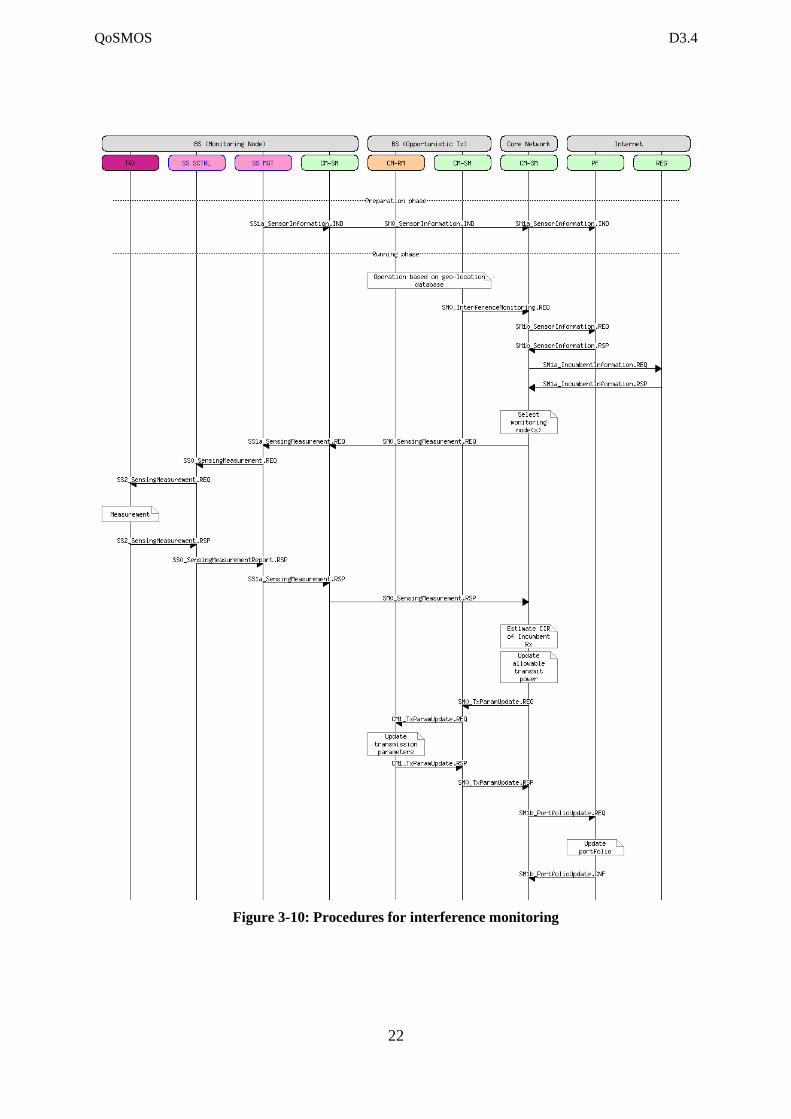
The procedure for the interference monitoring is presented in [D2.3]. This section updates and
elaborates the procedure in a particular focus on the spectrum sensing entity which measures
interference and incumbent signal. The procedure for the interference monitoring is shown in
Figure 3-10, and the primitives involved in the interference monitoring are summarised in Table 6-1 in
the annex. The interference monitoring procedure is divided into two phases: the preparation phase;
and the running phase.
The preparation phase is for each BS which has monitoring capability to register its sensor information
to the Prtfolio Repository (PF). This is supposed to be done when a BS is set up in the system. When a
new BS is added, this procedure for sensor information registration can also run even if the
interference monitoring has been operating in the running phase.
In the running phase, the CM-SM in the BS initiates the interference monitoring. CM-SM in the core
network requests the sensor information from the PF and the incumbent system information from the
REGulatory databases (REG). Using this information, the CM-SM selects a monitoring node(s) which
is located near the worst-case incumbent receiver which will receive the largest interference from the
operating opportunistic TX. Then, the CM-SM sends the request for measurement to the selected
monitoring node, which also specifies the sensing information such as target channel and time etc.
SS MGT in the monitoring node receives the request from the local CM-SM. Through SS SCTRL, the
SS MGT notifies the TRX to receive the radio signals in the target channel and time. SS SCTRL
calculates the interference power and incumbent signal power based on the received baseband signals
provided by TRX. Then, the calculated measurement results are sent to SS MGT. If needed, the
received power of the interference and incumbent signal can be quantised at SS MGT. The SS MGT
reports the signal levels to the CM-SM in the core network. Note that adaptation layer between the SS
MGT and CM-SM is not shown in Figure 3-10 for simplicity.
After receiving the measurement results, the CM-SM in the core network estimates CIR at the
incumbent receiver and updates the allowable transmit power of the opportunistic Tx, which are
addressed more in detail in [D6.3]. According to the updated allowable transmit power, CM-RM in the
opportunistic Tx determines operating parameters such as the operating transmit power or the channel
to use. This information is sent back to the CM-SM in the core network and also stored in the PF.
Incumbent Tx Opportunistic TxIncumbent Rx Monitoring Node
CM-SM in Core Network
QoSMOS D3.4
22
Figure 3-10: Procedures for interference monitoring
QoSMOS D3.4
23
4 Requirements for Radio Environment Context Acquisition
Protocol Stack
To settle the requirements for the protocol stack messages first a short recapitulation on the
capabilities and definitions proposed by P1900.6 [P1900] is given. Additionally, a short overview on
the SotA on position acquisition is given. Then, the main requirements are derived from the QoSMOS
system requirements and the related building block CM-RM and CM-SM. To complete this, these
requirements are completed with those imposed by LTE and IEEE 802.11.
4.1 Specification as Proposed by IEEE1900.6
The scope on the IEEE DYSPAN 1900.6 group relates to “Spectrum Sensing Interfaces and Data
Structures for Dynamic Spectrum Access and other Advanced Radio Communication Systems”. IEEE
1900.6 standardizes the information exchange between spectrum sensors and their clients in advanced
radio communication systems in a technology neutral way. Indeed, the logical interface and supporting
data structures used for information exchange are defined abstractly without constraining the sensing
technology, client design, or data link between sensors and their clients. This means that the protocol
stack on the information exchange channel is not specified with and implementation approach in mind
but rather describe the architecture of such a structure. A first version of the IEEE Standard 1900.6-
2011 was published on April 22nd 2011. [Moess11] and [Murro11] recap the main concepts
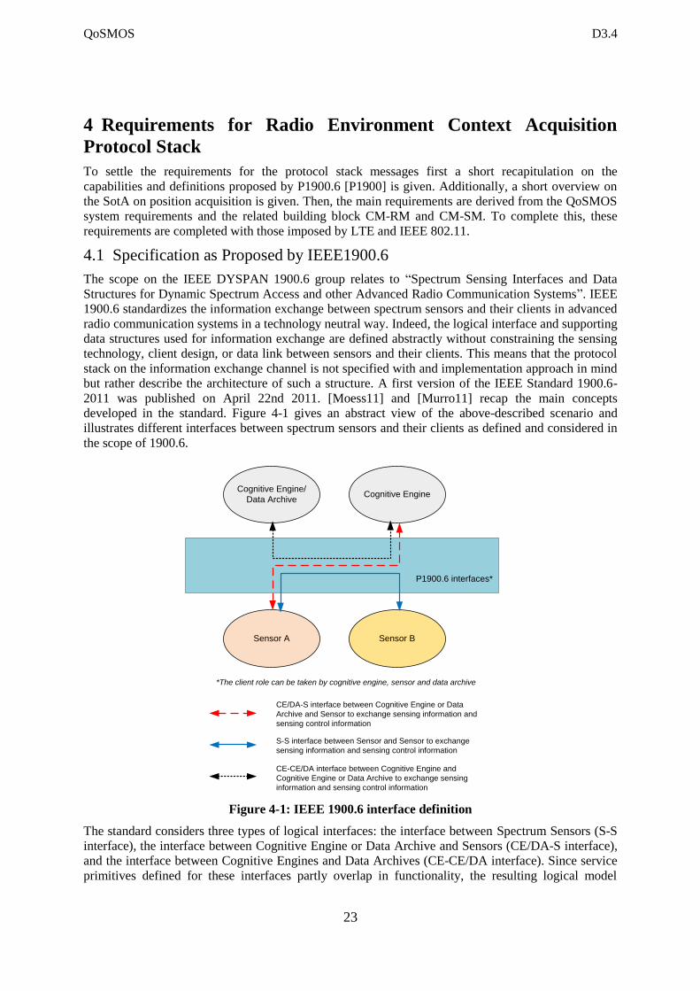
developed in the standard. Figure 4-1 gives an abstract view of the above-described scenario and
illustrates different interfaces between spectrum sensors and their clients as defined and considered in
the scope of 1900.6.
P1900.6 interfaces*
Sensor A
Cognitive Engine/
Data Archive
Sensor B
Cognitive Engine
*The client role can be taken by cognitive engine, sensor and data archive
CE/DA-S interface between Cognitive Engine or Data
Archive and Sensor to exchange sensing information and
sensing control information
S-S interface between Sensor and Sensor to exchange
sensing information and sensing control information
CE-CE/DA interface between Cognitive Engine and
Cognitive Engine or Data Archive to exchange sensing
information and sensing control information
Figure 4-1: IEEE 1900.6 interface definition
The standard considers three types of logical interfaces: the interface between Spectrum Sensors (S-S
interface), the interface between Cognitive Engine or Data Archive and Sensors (CE/DA-S interface),
and the interface between Cognitive Engines and Data Archives (CE-CE/DA interface). Since service
primitives defined for these interfaces partly overlap in functionality, the resulting logical model
QoSMOS D3.4
24
includes options to forward sensing related information across multiple realizations of a CE or DA
entity, such as in common radio access networks where CE or DA might be collocated with base
stations. Future extensions to the standard hence will allow interfacing sensors with external entities,
such as geolocation databases. IEEE 1900.6 logical entities rely upon platform services that are by
intention not specified further by the standard. Instead, the standard specifies the service access points
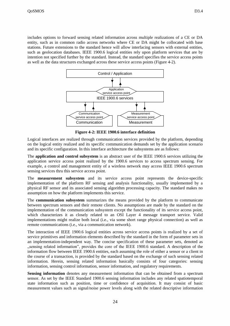
as well as the data structures exchanged across these service access points (Figure 4-2).
Figure 4-2: IEEE 1900.6 interface definition
Logical interfaces are realized through communication services provided by the platform, depending
on the logical entity realized and its specific communication demands set by the application scenario
and its specific configuration. In this interface architecture the subsystems are as follows:
The application and control subsystem is an abstract user of the IEEE 1900.6 services utilizing the
application service access point realized by the 1900.6 services to access spectrum sensing. For
example, a control and management entity of a wireless network may access IEEE 1900.6 spectrum
sensing services thru this service access point.
The measurement subsystem and its service access point represents the device-specific
implementation of the platform RF sensing and analysis functionality, usually implemented by a
physical RF sensor and its associated sensing algorithm processing capacity. The standard makes no
assumption on how the platform implements this service.
The communication subsystem summarizes the means provided by the platform to communicate
between spectrum sensors and their remote clients. No assumptions are made by the standard on the
implementation of the communication subsystem except the functionality of its service access point,
which characterizes it as closely related to an OSI Layer 4 message transport service. Valid
implementations might realize both local (i.e., via some short range physical connection) as well as
remote communications (i.e., via a communication network).
The interaction of IEEE 1900.6 logical entities across service access points is realized by a set of
service primitives and information elements described by the standard in the form of parameter sets in
an implementation-independent way. The concise specification of these parameter sets, denoted as
„sensing related information”, provides the core of the IEEE 1900.6 standard. A description of the
information flow between IEEE 1900.6 entities, each assuming the role of either a sensor or a client in
the course of a transaction, is provided by the standard based on the exchange of such sensing related
information. Herein, sensing related information basically consists of four categories: sensing
information, sensing control information, sensor information, and regulatory requirements.
Sensing information denotes any measurement information that can be obtained from a spectrum
sensor. As set by the IEEE Standard 1900.6 sensing information includes any related spatiotemporal
state information such as position, time or confidence of acquisition. It may consist of basic
measurement values such as signal/noise power levels along with the related descriptive information
IEEE 1900.6 services
Communication Measurement
Communication
service access point
Measurement
service access point
Application
service access point
Control / Application
QoSMOS D3.4
25
such as measurement bandwidth and centre frequency. Depending on a sensor’s capabilities and
algorithms available sensing information may also consist of more complex descriptions of the
observed RF environment such as signal type, modulation type and traffic pattern of the detected
remote spectrum user. In a distributed sensing scenario this sensing information may be the outcome
of multiple spatially distributed RF sensing processes.
Sensing control denotes any information required to describe the status or configuration and to
control or configure the data acquisition and RF sensing process of a spectrum sensor. Sensing control
information is not much different from the sensing information, sharing most of the basic information
elements (i.e., parameters), but is mainly used in the course of exchanging control commands. For
example, RF bandwidth and centre frequency are sensing information in conjunction with the
measured data obtained from a sensor but they act as sensing control information when used for tuning
the spectrum sensor into a new measurement process. Depending on the sensing capabilities of a
sensor, sensing control information may become more complex and descriptive (i.e., describing a
sensing strategy rather than setting a single sensing parameter) as in, for example, setting the scanning
scheme within a given upper and lower frequency bound using a certain sweep and sojourn time for
each intermediate scan step attained.
Sensor information denotes the parameters used to describe the capabilities of a spectrum sensor.
Sensor information can be requested from a spectrum sensor to learn about its properties, usually
describing its limitations of operation in form of operational parameters such as frequency range,
accuracy and similar objectives. In this context, a client may also obtain the sensor’s absolute limits of
operation by requesting the sensor’s electronic data sheet prepared by the sensor manufacturer. It
should be noted here that the data sheet providing sensor information is considered complementary
since real operational limits and confidence achieved by a spectrum sensor very much depend on the
current operating conditions as well as on the RF environment describing the current operational
context.
Regulatory requirements are unique for the application area of dynamic spectrum access by
cognitive radios. Regulatory requirements are expressed by the same sensing and sensing control
parameters as discussed above, but they denote obligations of a spectrum sensor rather than
measurement or control parameters. They may be used to control and configure a spectrum sensor but
may also be used to evaluate if a sensor satisfies given demands in terms of accuracy, confidence,
granularity, sensitivity or similar. Hence, there is only a fuzzy boundary between regulatory
requirements expressed as a set of sensing related parameters and regulatory policies.
The IEEE Std 1900.6-2011 [P1900] provides a sound baseline for a standardized information
exchange between spectrum sensors and their clients. It clearly goes beyond a mere specification of a
physical communication between sensing equipment and RF context analysis, and provides a logical
and architectural view to the logical entities, services and interfaces involved in a distributed spectrum
sensing process. Due to technological neutrality, it will be used as a baseline standard for sensing
protocol stack definition in QoSMOS. However, IEEE Std 1900.6-2011 [P1900] does not provide any
information on how this should be done and how it shall be implemented.
4.2 Overview on SotA Position Context Acquisition Techniques
The radio environment context acquisition is the process used to obtain the spectrum environment for
the opportunistic radio. One mechanism that has already been extensively reported in QoSMOS is
spectrum sensing [D3.3]. Another ‘sensing’ technique that is also envisaged and seems to be preferred
for TVWS applications is based on geolocation and database queries. We propose here to make a brief
review of the geolocation in order to understand the advantages but also the limitations of these
techniques.
Geolocation is a process used to obtain the position of the user terminal and is sometimes also referred
as positioning. Positioning methods may be classified by the technique employed to derive the
position of the user, these are: proximity sensing, multilateration, goniometry, dead reckoning pattern
QoSMOS D3.4
26
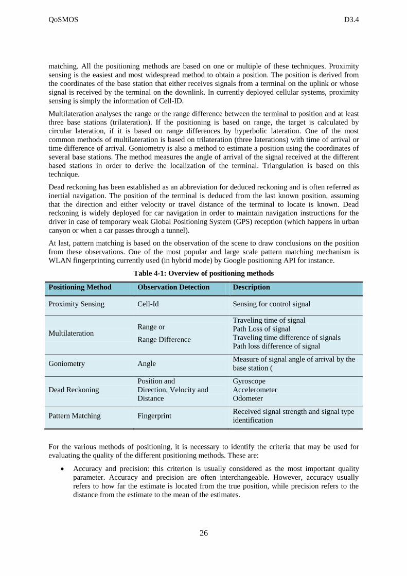
matching. All the positioning methods are based on one or multiple of these techniques. Proximity
sensing is the easiest and most widespread method to obtain a position. The position is derived from
the coordinates of the base station that either receives signals from a terminal on the uplink or whose
signal is received by the terminal on the downlink. In currently deployed cellular systems, proximity
sensing is simply the information of Cell-ID.
Multilateration analyses the range or the range difference between the terminal to position and at least
three base stations (trilateration). If the positioning is based on range, the target is calculated by
circular lateration, if it is based on range differences by hyperbolic lateration. One of the most
common methods of multilateration is based on trilateration (three laterations) with time of arrival or
time difference of arrival. Goniometry is also a method to estimate a position using the coordinates of
several base stations. The method measures the angle of arrival of the signal received at the different
based stations in order to derive the localization of the terminal. Triangulation is based on this
technique.
Dead reckoning has been established as an abbreviation for deduced reckoning and is often referred as
inertial navigation. The position of the terminal is deduced from the last known position, assuming
that the direction and either velocity or travel distance of the terminal to locate is known. Dead
reckoning is widely deployed for car navigation in order to maintain navigation instructions for the
driver in case of temporary weak Global Positioning System (GPS) reception (which happens in urban
canyon or when a car passes through a tunnel).
At last, pattern matching is based on the observation of the scene to draw conclusions on the position
from these observations. One of the most popular and large scale pattern matching mechanism is
WLAN fingerprinting currently used (in hybrid mode) by Google positioning API for instance.
Table 4-1: Overview of positioning methods
Positioning Method Observation Detection Description
Proximity Sensing Cell-Id Sensing for control signal
Multilateration Range or
Range Difference
Traveling time of signal
Path Loss of signal
Traveling time difference of signals
Path loss difference of signal
Goniometry Angle Measure of signal angle of arrival by the
base station (
Dead Reckoning
Position and
Direction, Velocity and
Distance
Gyroscope
Accelerometer
Odometer
Pattern Matching Fingerprint Received signal strength and signal type
identification
For the various methods of positioning, it is necessary to identify the criteria that may be used for
evaluating the quality of the different positioning methods. These are:
Accuracy and precision: this criterion is usually considered as the most important quality
parameter. Accuracy and precision are often interchangeable. However, accuracy usually
refers to how far the estimate is located from the true position, while precision refers to the
distance from the estimate to the mean of the estimates.
QoSMOS D3.4
27
Yield and consistency: yield refers to the ability of the method to estimate positions in all
environments (for instance indoor or outdoor, in urban canyon and rural areas), while
consistency is a measure for the stability of accuracy in different environments.
Latency: refers to the time period between the request of a position and the delivery of the
position estimate. Sometimes in positioning techniques, latency is measured by the time to
first fix as position is tracked over time.
Overhead and power consumption: refers to the cost of the method. Overhead includes extra
infrastructure or signalling required for the method. Power consumption is mainly of
importance at the battery powered terminal.
Out of the currently available positioning techniques, three families of technique are of particular
interest as they have been widely used and tested. These are satellite positioning, cellular positioning
and Wi-Fi positioning techniques.
Satellite Positioning
Satellite navigation systems have been popularized by the advances of the U.S. American Global
Positioning System from the mid 1990’s as positioning receivers became widely available for mass
market applications. The system has been developed in the end of the 70’s and has been an aid to
civilian navigation worldwide since 1983. Although GPS is the most famous satellite positioning
systems worldwide, other competing systems use similar principles. This is the case of the European
System Galileo (currently not fully operational) or the Russian system GLONASS or the future
Chinese system Compass. Some plan to propose a worldwide coverage while others have a more
regional coverage, such as the Indian Regional Navigational Satellite System (IRNSS).
The GPS system is composed of a fleet of up to 32 satellites orbiting in 6 different orbital planes with
an orbital period of around 12 hours. Currently 31 satellites form the so called space segment of the
GPS. The operation of positioning comprises three steps: identification of satellites, range
measurements and position calculations.
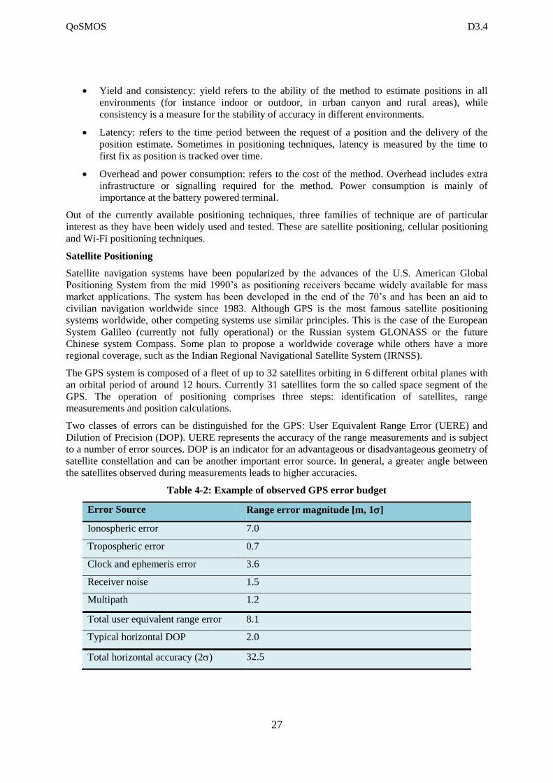
Two classes of errors can be distinguished for the GPS: User Equivalent Range Error (UERE) and
Dilution of Precision (DOP). UERE represents the accuracy of the range measurements and is subject
to a number of error sources. DOP is an indicator for an advantageous or disadvantageous geometry of
satellite constellation and can be another important error source. In general, a greater angle between
the satellites observed during measurements leads to higher accuracies.
Table 4-2: Example of observed GPS error budget
Error Source Range error magnitude [m, 1]
Ionospheric error 7.0
Tropospheric error 0.7
Clock and ephemeris error 3.6
Receiver noise 1.5
Multipath 1.2
Total user equivalent range error 8.1
Typical horizontal DOP 2.0
Total horizontal accuracy (2) 32.5
QoSMOS D3.4
28
Assisted GPS or A-GPS has been invented to reduce the Time To First Fix (TTFF) of the GPS (i.e.:
the time the GPS receiver takes to acquire a position). The cellular network provides the almanac
(orbit and status information for each satellite in the constellation) and a rough initial position of the
user to speed-up the estimation of the position.
Cellular Network Positioning Technologies
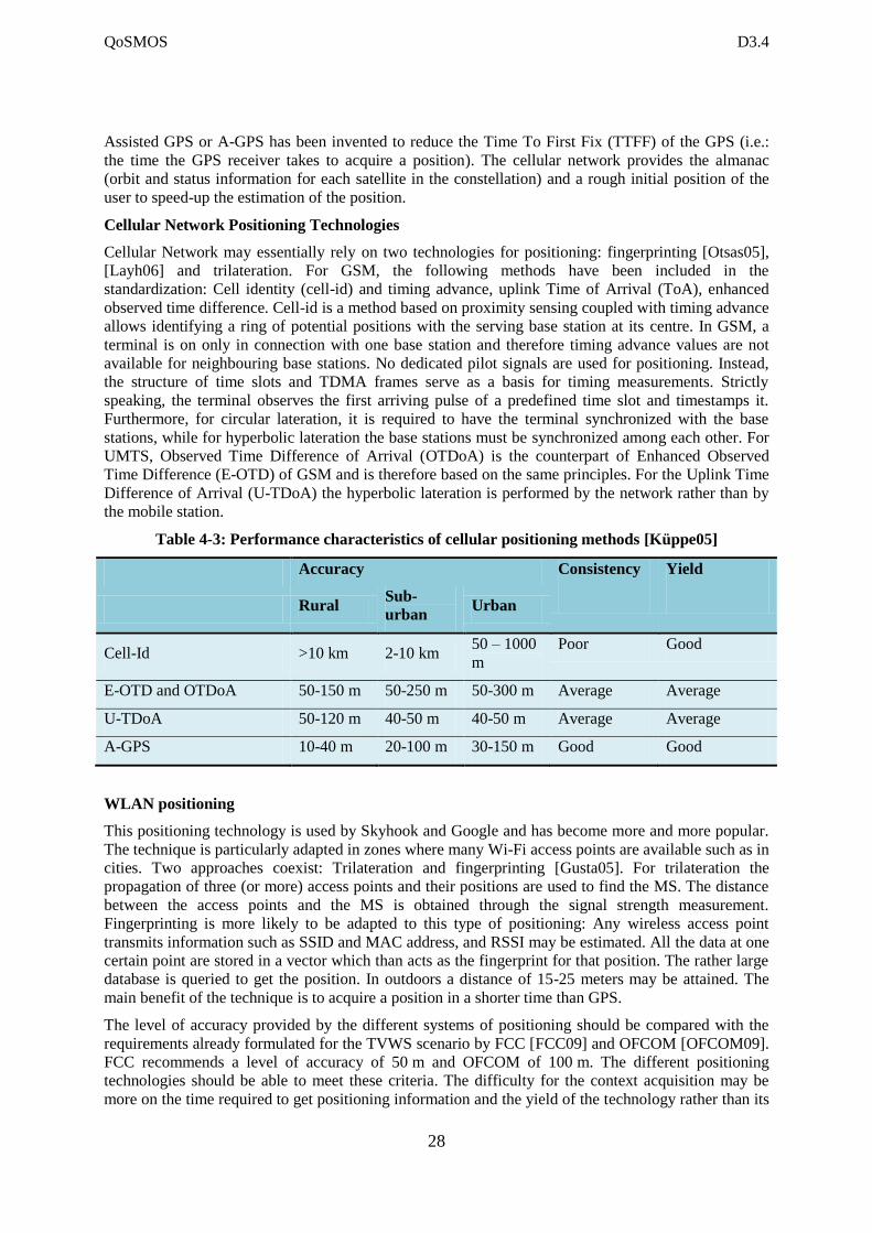
Cellular Network may essentially rely on two technologies for positioning: fingerprinting [Otsas05],
[Layh06] and trilateration. For GSM, the following methods have been included in the
standardization: Cell identity (cell-id) and timing advance, uplink Time of Arrival (ToA), enhanced
observed time difference. Cell-id is a method based on proximity sensing coupled with timing advance
allows identifying a ring of potential positions with the serving base station at its centre. In GSM, a
terminal is on only in connection with one base station and therefore timing advance values are not
available for neighbouring base stations. No dedicated pilot signals are used for positioning. Instead,
the structure of time slots and TDMA frames serve as a basis for timing measurements. Strictly
speaking, the terminal observes the first arriving pulse of a predefined time slot and timestamps it.
Furthermore, for circular lateration, it is required to have the terminal synchronized with the base
stations, while for hyperbolic lateration the base stations must be synchronized among each other. For
UMTS, Observed Time Difference of Arrival (OTDoA) is the counterpart of Enhanced Observed
Time Difference (E-OTD) of GSM and is therefore based on the same principles. For the Uplink Time
Difference of Arrival (U-TDoA) the hyperbolic lateration is performed by the network rather than by
the mobile station.
Table 4-3: Performance characteristics of cellular positioning methods [Küppe05]
Accuracy Consistency Yield
Rural Sub-
urban Urban
Cell-Id >10 km 2-10 km 50 – 1000
m
Poor Good
E-OTD and OTDoA 50-150 m 50-250 m 50-300 m Average Average
U-TDoA 50-120 m 40-50 m 40-50 m Average Average
A-GPS 10-40 m 20-100 m 30-150 m Good Good
WLAN positioning
This positioning technology is used by Skyhook and Google and has become more and more popular.
The technique is particularly adapted in zones where many Wi-Fi access points are available such as in
cities. Two approaches coexist: Trilateration and fingerprinting [Gusta05]. For trilateration the
propagation of three (or more) access points and their positions are used to find the MS. The distance
between the access points and the MS is obtained through the signal strength measurement.
Fingerprinting is more likely to be adapted to this type of positioning: Any wireless access point
transmits information such as SSID and MAC address, and RSSI may be estimated. All the data at one
certain point are stored in a vector which than acts as the fingerprint for that position. The rather large
database is queried to get the position. In outdoors a distance of 15-25 meters may be attained. The
main benefit of the technique is to acquire a position in a shorter time than GPS.
The level of accuracy provided by the different systems of positioning should be compared with the
requirements already formulated for the TVWS scenario by FCC [FCC09] and OFCOM [OFCOM09].
FCC recommends a level of accuracy of 50 m and OFCOM of 100 m. The different positioning
technologies should be able to meet these criteria. The difficulty for the context acquisition may be
more on the time required to get positioning information and the yield of the technology rather than its
QoSMOS D3.4
29
actual level of accuracy. In conclusion, all of these methods can be used to gather the position in a
QoSMOS system.
4.3 Requirements Derived from QoSMOS System Requirements
In the following we will list requirements for the protocol stack messages which are induced by the
QoSMOS scenarios and the deduced QoSMOS system requirements. A detailed description of the
scenarios can be found in [D1.2] whereas the system requirements are introduced in [D1.4]. We do not
repeat these here.
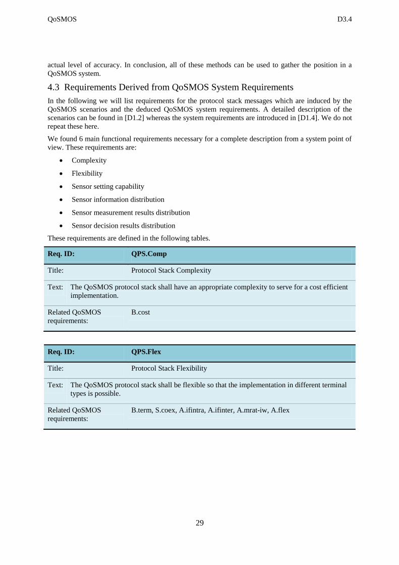
We found 6 main functional requirements necessary for a complete description from a system point of
view. These requirements are:
Complexity
Flexibility
Sensor setting capability
Sensor information distribution
Sensor measurement results distribution
Sensor decision results distribution
These requirements are defined in the following tables.
Req. ID: QPS.Comp
Title: Protocol Stack Complexity
Text: The QoSMOS protocol stack shall have an appropriate complexity to serve for a cost efficient
implementation.
Related QoSMOS
requirements:
B.cost
Req. ID: QPS.Flex
Title: Protocol Stack Flexibility
Text: The QoSMOS protocol stack shall be flexible so that the implementation in different terminal
types is possible.
Related QoSMOS
requirements:
B.term, S.coex, A.ifintra, A.ifinter, A.mrat-iw, A.flex
QoSMOS D3.4
30
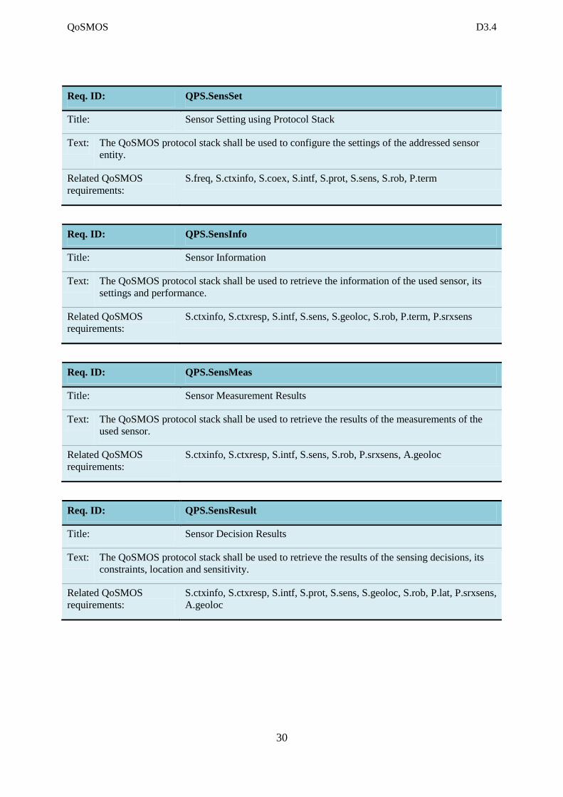
Req. ID: QPS.SensSet
Title: Sensor Setting using Protocol Stack
Text: The QoSMOS protocol stack shall be used to configure the settings of the addressed sensor
entity.
Related QoSMOS
requirements:
S.freq, S.ctxinfo, S.coex, S.intf, S.prot, S.sens, S.rob, P.term
Req. ID: QPS.SensInfo
Title: Sensor Information
Text: The QoSMOS protocol stack shall be used to retrieve the information of the used sensor, its
settings and performance.
Related QoSMOS
requirements:
S.ctxinfo, S.ctxresp, S.intf, S.sens, S.geoloc, S.rob, P.term, P.srxsens
Req. ID: QPS.SensMeas
Title: Sensor Measurement Results
Text: The QoSMOS protocol stack shall be used to retrieve the results of the measurements of the
used sensor.
Related QoSMOS
requirements:
S.ctxinfo, S.ctxresp, S.intf, S.sens, S.rob, P.srxsens, A.geoloc
Req. ID: QPS.SensResult
Title: Sensor Decision Results
Text: The QoSMOS protocol stack shall be used to retrieve the results of the sensing decisions, its
constraints, location and sensitivity.
Related QoSMOS
requirements:
S.ctxinfo, S.ctxresp, S.intf, S.prot, S.sens, S.geoloc, S.rob, P.lat, P.srxsens,
A.geoloc
QoSMOS D3.4
31
4.4 Requirements from CM-RM and CM-SM
Spectrum sensing may be exploited for different scopes at CM-RM and CM-SM. The CM-SM may
use spectrum sensing to build-up or maintain the radio context, whereas the CM-RM may need
spectrum sensing for incumbent detection (when applicable). The results available at the CM-RM may
be exploited also by the CM-SM.
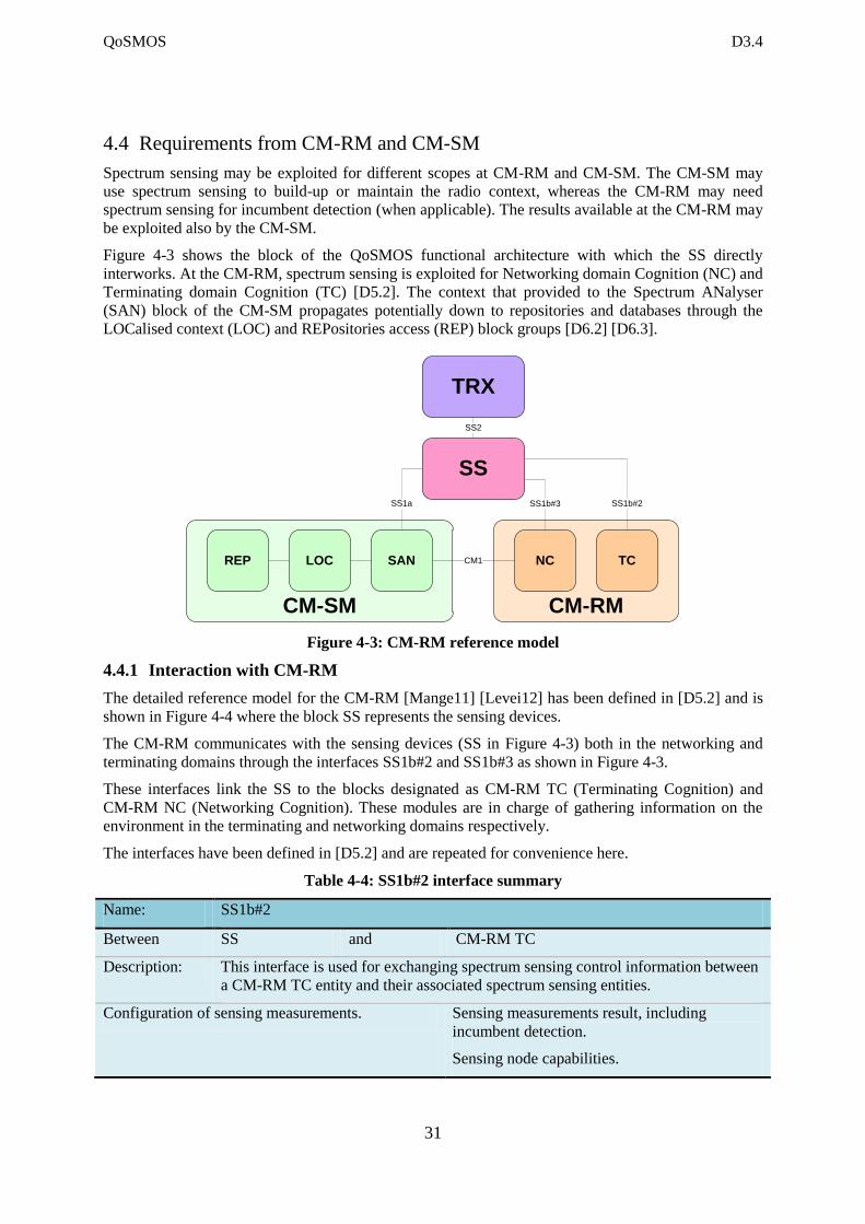
Figure 4-3 shows the block of the QoSMOS functional architecture with which the SS directly
interworks. At the CM-RM, spectrum sensing is exploited for Networking domain Cognition (NC) and
Terminating domain Cognition (TC) [D5.2]. The context that provided to the Spectrum ANalyser
(SAN) block of the CM-SM propagates potentially down to repositories and databases through the
LOCalised context (LOC) and REPositories access (REP) block groups [D6.2] [D6.3].
Figure 4-3: CM-RM reference model
4.4.1 Interaction with CM-RM
The detailed reference model for the CM-RM [Mange11] [Levei12] has been defined in [D5.2] and is
shown in Figure 4-4 where the block SS represents the sensing devices.
The CM-RM communicates with the sensing devices (SS in Figure 4-3) both in the networking and
terminating domains through the interfaces SS1b#2 and SS1b#3 as shown in Figure 4-3.
These interfaces link the SS to the blocks designated as CM-RM TC (Terminating Cognition) and
CM-RM NC (Networking Cognition). These modules are in charge of gathering information on the
environment in the terminating and networking domains respectively.
The interfaces have been defined in [D5.2] and are repeated for convenience here.
Table 4-4: SS1b#2 interface summary
Name: SS1b#2
Between SS and CM-RM TC
Description: This interface is used for exchanging spectrum sensing control information between
a CM-RM TC entity and their associated spectrum sensing entities.
Configuration of sensing measurements. Sensing measurements result, including
incumbent detection.
Sensing node capabilities.
CM-RM
NC TC
CM-SM
TRX
SS1b#2
SS
SS1b#3
SAN
SS1a
LOCREP
SS2
CM1
QoSMOS D3.4
32
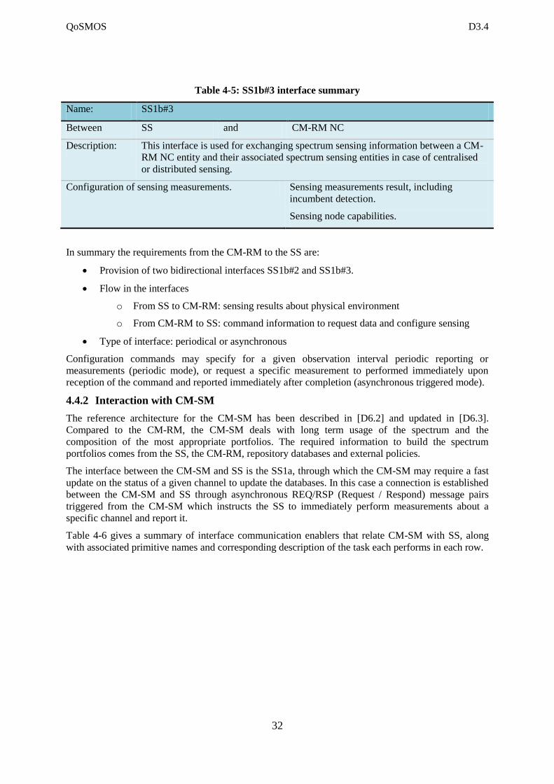
Table 4-5: SS1b#3 interface summary
Name: SS1b#3
Between SS and CM-RM NC
Description: This interface is used for exchanging spectrum sensing information between a CM-
RM NC entity and their associated spectrum sensing entities in case of centralised
or distributed sensing.
Configuration of sensing measurements. Sensing measurements result, including
incumbent detection.
Sensing node capabilities.
In summary the requirements from the CM-RM to the SS are:
Provision of two bidirectional interfaces SS1b#2 and SS1b#3.
Flow in the interfaces
o From SS to CM-RM: sensing results about physical environment
o From CM-RM to SS: command information to request data and configure sensing
Type of interface: periodical or asynchronous
Configuration commands may specify for a given observation interval periodic reporting or
measurements (periodic mode), or request a specific measurement to performed immediately upon
reception of the command and reported immediately after completion (asynchronous triggered mode).
4.4.2 Interaction with CM-SM
The reference architecture for the CM-SM has been described in [D6.2] and updated in [D6.3].
Compared to the CM-RM, the CM-SM deals with long term usage of the spectrum and the
composition of the most appropriate portfolios. The required information to build the spectrum
portfolios comes from the SS, the CM-RM, repository databases and external policies.
The interface between the CM-SM and SS is the SS1a, through which the CM-SM may require a fast
update on the status of a given channel to update the databases. In this case a connection is established
between the CM-SM and SS through asynchronous REQ/RSP (Request / Respond) message pairs
triggered from the CM-SM which instructs the SS to immediately perform measurements about a
specific channel and report it.
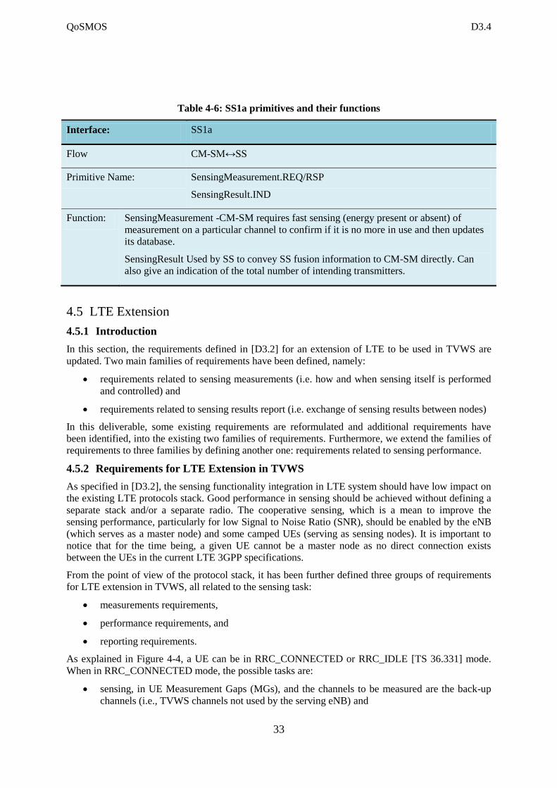
Table 4-6 gives a summary of interface communication enablers that relate CM-SM with SS, along
with associated primitive names and corresponding description of the task each performs in each row.
QoSMOS D3.4
33
Table 4-6: SS1a primitives and their functions
Interface: SS1a
Flow CM-SM↔SS
Primitive Name: SensingMeasurement.REQ/RSP
SensingResult.IND
Function: SensingMeasurement -CM-SM requires fast sensing (energy present or absent) of
measurement on a particular channel to confirm if it is no more in use and then updates
its database.
SensingResult Used by SS to convey SS fusion information to CM-SM directly. Can
also give an indication of the total number of intending transmitters.
4.5 LTE Extension
4.5.1 Introduction
In this section, the requirements defined in [D3.2] for an extension of LTE to be used in TVWS are
updated. Two main families of requirements have been defined, namely:
requirements related to sensing measurements (i.e. how and when sensing itself is performed
and controlled) and
requirements related to sensing results report (i.e. exchange of sensing results between nodes)
In this deliverable, some existing requirements are reformulated and additional requirements have
been identified, into the existing two families of requirements. Furthermore, we extend the families of
requirements to three families by defining another one: requirements related to sensing performance.
4.5.2 Requirements for LTE Extension in TVWS
As specified in [D3.2], the sensing functionality integration in LTE system should have low impact on
the existing LTE protocols stack. Good performance in sensing should be achieved without defining a
separate stack and/or a separate radio. The cooperative sensing, which is a mean to improve the
sensing performance, particularly for low Signal to Noise Ratio (SNR), should be enabled by the eNB
(which serves as a master node) and some camped UEs (serving as sensing nodes). It is important to
notice that for the time being, a given UE cannot be a master node as no direct connection exists
between the UEs in the current LTE 3GPP specifications.
From the point of view of the protocol stack, it has been further defined three groups of requirements
for LTE extension in TVWS, all related to the sensing task:
measurements requirements,
performance requirements, and
reporting requirements.
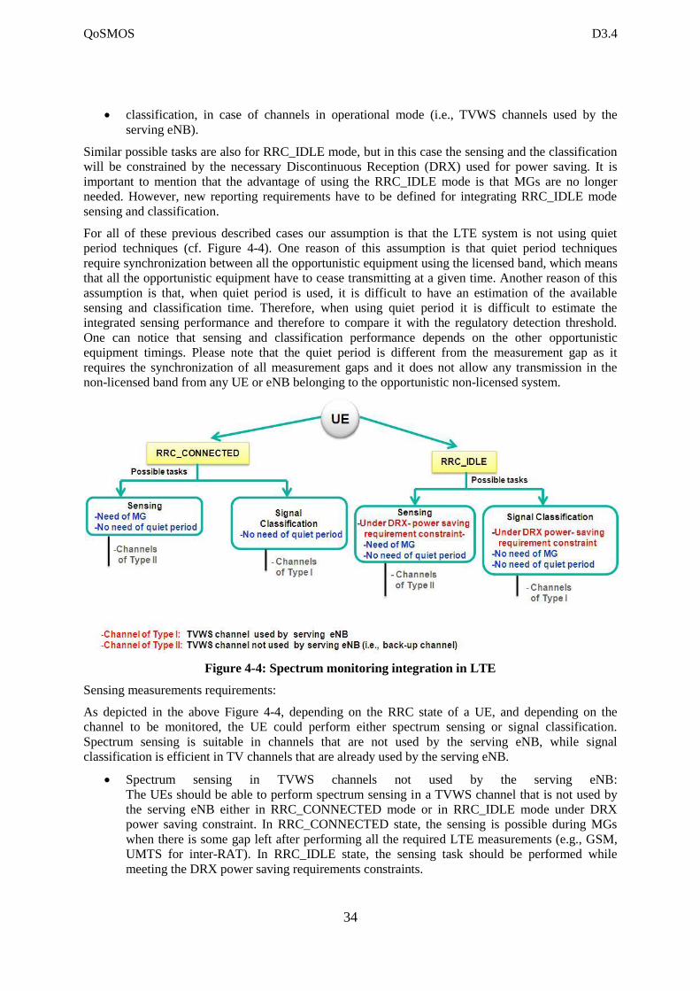
As explained in Figure 4-4, a UE can be in RRC_CONNECTED or RRC_IDLE [TS 36.331] mode.
When in RRC_CONNECTED mode, the possible tasks are:
sensing, in UE Measurement Gaps (MGs), and the channels to be measured are the back-up
channels (i.e., TVWS channels not used by the serving eNB) and
QoSMOS D3.4
34
classification, in case of channels in operational mode (i.e., TVWS channels used by the
serving eNB).
Similar possible tasks are also for RRC_IDLE mode, but in this case the sensing and the classification
will be constrained by the necessary Discontinuous Reception (DRX) used for power saving. It is
important to mention that the advantage of using the RRC_IDLE mode is that MGs are no longer
needed. However, new reporting requirements have to be defined for integrating RRC_IDLE mode
sensing and classification.
For all of these previous described cases our assumption is that the LTE system is not using quiet
period techniques (cf. Figure 4-4). One reason of this assumption is that quiet period techniques
require synchronization between all the opportunistic equipment using the licensed band, which means
that all the opportunistic equipment have to cease transmitting at a given time. Another reason of this
assumption is that, when quiet period is used, it is difficult to have an estimation of the available
sensing and classification time. Therefore, when using quiet period it is difficult to estimate the
integrated sensing performance and therefore to compare it with the regulatory detection threshold.
One can notice that sensing and classification performance depends on the other opportunistic
equipment timings. Please note that the quiet period is different from the measurement gap as it
requires the synchronization of all measurement gaps and it does not allow any transmission in the
non-licensed band from any UE or eNB belonging to the opportunistic non-licensed system.
Figure 4-4: Spectrum monitoring integration in LTE
Sensing measurements requirements:
As depicted in the above Figure 4-4, depending on the RRC state of a UE, and depending on the
channel to be monitored, the UE could perform either spectrum sensing or signal classification.
Spectrum sensing is suitable in channels that are not used by the serving eNB, while signal
classification is efficient in TV channels that are already used by the serving eNB.
Spectrum sensing in TVWS channels not used by the serving eNB:
The UEs should be able to perform spectrum sensing in a TVWS channel that is not used by
the serving eNB either in RRC_CONNECTED mode or in RRC_IDLE mode under DRX
power saving constraint. In RRC_CONNECTED state, the sensing is possible during MGs
when there is some gap left after performing all the required LTE measurements (e.g., GSM,
UMTS for inter-RAT). In RRC_IDLE state, the sensing task should be performed while
meeting the DRX power saving requirements constraints.
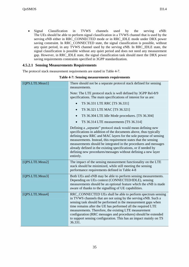
QoSMOS D3.4
35
Signal Classification in TVWS channels used by the serving eNB:
The UEs should be able to perform signal classification in a TVWS channel that is used by the
serving eNB either in RRC_CONNECTED mode or in RRC_IDLE mode under DRX power
saving constraint. In RRC_CONNECTED state, the signal classification is possible, without
any quiet period, in any TVWS channel used by the serving eNB. In RRC_IDLE state, the
signal classification is possible without any quiet period and does not need any measurement
gap. However, in RRC_IDLE state, the signal classification task should meet the DRX power
saving requirements constraints specified in 3GPP standardization.
4.5.2.1 Sensing Measurements Requirements
The protocol stack measurement requirements are stated in Table 4-7.
Table 4-7: Sensing measurements requirements
[QPS.LTE.Meas1] There should not be a separate protocol stack defined for sensing
measurements.
Note: The LTE protocol stack is well defined by 3GPP Rel-8/9
specifications. The main specifications of interest for us are:
TS 36.331 LTE RRC [TS 36.331]
TS 36.321 LTE MAC [TS 36.321]
TS 36.304 LTE Idle Mode procedures. [TS 36.304]
TS 36.314 LTE measurements [TS 36.314]
Defining a „separate” protocol stack would mean defining new
specifications in addition of the documents above, thus typically
defining new RRC and MAC layers for the sole purpose of sensing
measurements. Instead, this requirement states that the sensing
measurements should be integrated in the procedures and messages
already defined in the existing specifications, or if needed by
defining new procedures/messages without defining a new layer
entirely.
[QPS.LTE.Meas2] The impact of the sensing measurement functionality on the LTE
stack should be minimized, while still meeting the sensing
performance requirements defined in Table 4-8
[QPS.LTE.Meas3] Both UEs and eNB may be able to perform sensing measurements.
Depending on UEs context (CONNECTED/IDLE), sensing
measurements should be an optional feature which the eNB is made
aware of thanks to the signalling of UE capabilities.
[QPS.LTE.Meas4] RRC_CONNECTED UEs shall be able to perform spectrum sensing
in TVWS channels that are not using by the serving eNB. Such a
sensing task should be performed in the measurement gaps when
time remains after the UE has performed all the required LTE
measurements. Therefore, the existing LTE measurement
configuration (RRC messages and procedures) should be extended
to support sensing configuration. This has an impact mainly on TS
36.331.
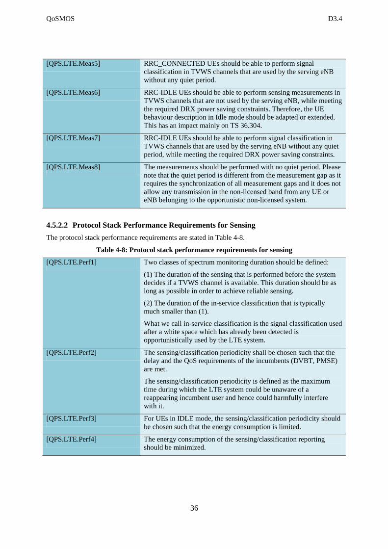
QoSMOS D3.4
36
[QPS.LTE.Meas5] RRC_CONNECTED UEs should be able to perform signal
classification in TVWS channels that are used by the serving eNB
without any quiet period.
[QPS.LTE.Meas6] RRC-IDLE UEs should be able to perform sensing measurements in
TVWS channels that are not used by the serving eNB, while meeting
the required DRX power saving constraints. Therefore, the UE
behaviour description in Idle mode should be adapted or extended.
This has an impact mainly on TS 36.304.
[QPS.LTE.Meas7] RRC-IDLE UEs should be able to perform signal classification in
TVWS channels that are used by the serving eNB without any quiet
period, while meeting the required DRX power saving constraints.
[QPS.LTE.Meas8] The measurements should be performed with no quiet period. Please
note that the quiet period is different from the measurement gap as it
requires the synchronization of all measurement gaps and it does not
allow any transmission in the non-licensed band from any UE or
eNB belonging to the opportunistic non-licensed system.
4.5.2.2 Protocol Stack Performance Requirements for Sensing
The protocol stack performance requirements are stated in Table 4-8.
Table 4-8: Protocol stack performance requirements for sensing
[QPS.LTE.Perf1] Two classes of spectrum monitoring duration should be defined:
(1) The duration of the sensing that is performed before the system
decides if a TVWS channel is available. This duration should be as
long as possible in order to achieve reliable sensing.
(2) The duration of the in-service classification that is typically
much smaller than (1).
What we call in-service classification is the signal classification used
after a white space which has already been detected is
opportunistically used by the LTE system.
[QPS.LTE.Perf2] The sensing/classification periodicity shall be chosen such that the
delay and the QoS requirements of the incumbents (DVBT, PMSE)
are met.
The sensing/classification periodicity is defined as the maximum
time during which the LTE system could be unaware of a
reappearing incumbent user and hence could harmfully interfere
with it.
[QPS.LTE.Perf3] For UEs in IDLE mode, the sensing/classification periodicity should
be chosen such that the energy consumption is limited.
[QPS.LTE.Perf4] The energy consumption of the sensing/classification reporting
should be minimized.
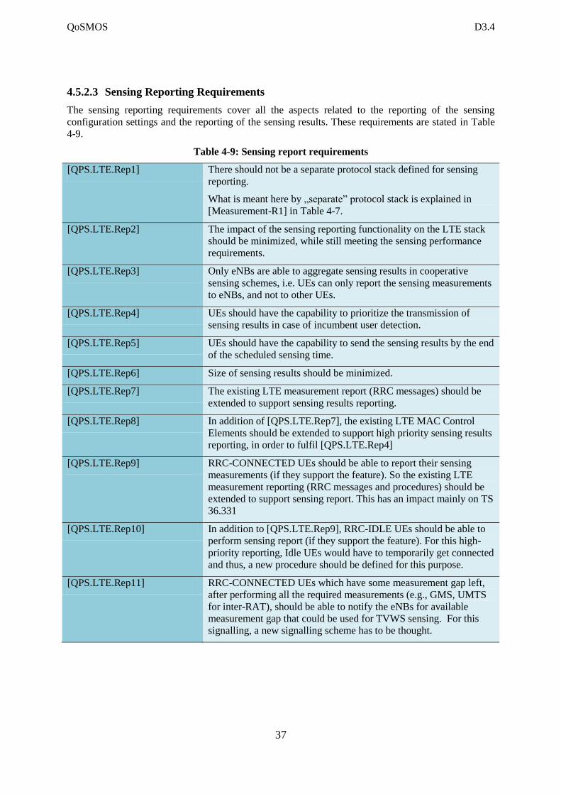
QoSMOS D3.4
37
4.5.2.3 Sensing Reporting Requirements
The sensing reporting requirements cover all the aspects related to the reporting of the sensing
configuration settings and the reporting of the sensing results. These requirements are stated in Table
4-9.
Table 4-9: Sensing report requirements
[QPS.LTE.Rep1] There should not be a separate protocol stack defined for sensing
reporting.
What is meant here by „separate” protocol stack is explained in
[Measurement-R1] in Table 4-7.
[QPS.LTE.Rep2] The impact of the sensing reporting functionality on the LTE stack
should be minimized, while still meeting the sensing performance
requirements.
[QPS.LTE.Rep3] Only eNBs are able to aggregate sensing results in cooperative
sensing schemes, i.e. UEs can only report the sensing measurements
to eNBs, and not to other UEs.
[QPS.LTE.Rep4] UEs should have the capability to prioritize the transmission of
sensing results in case of incumbent user detection.
[QPS.LTE.Rep5] UEs should have the capability to send the sensing results by the end
of the scheduled sensing time.
[QPS.LTE.Rep6] Size of sensing results should be minimized.
[QPS.LTE.Rep7] The existing LTE measurement report (RRC messages) should be
extended to support sensing results reporting.
[QPS.LTE.Rep8] In addition of [QPS.LTE.Rep7], the existing LTE MAC Control
Elements should be extended to support high priority sensing results
reporting, in order to fulfil [QPS.LTE.Rep4]
[QPS.LTE.Rep9] RRC-CONNECTED UEs should be able to report their sensing
measurements (if they support the feature). So the existing LTE
measurement reporting (RRC messages and procedures) should be
extended to support sensing report. This has an impact mainly on TS
36.331
[QPS.LTE.Rep10] In addition to [QPS.LTE.Rep9], RRC-IDLE UEs should be able to
perform sensing report (if they support the feature). For this high-
priority reporting, Idle UEs would have to temporarily get connected
and thus, a new procedure should be defined for this purpose.
[QPS.LTE.Rep11] RRC-CONNECTED UEs which have some measurement gap left,
after performing all the required measurements (e.g., GMS, UMTS
for inter-RAT), should be able to notify the eNBs for available
measurement gap that could be used for TVWS sensing. For this
signalling, a new signalling scheme has to be thought.
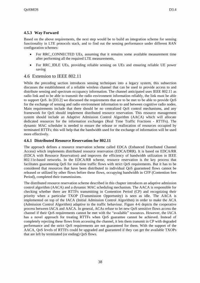
QoSMOS D3.4
38
4.5.3 Way Forward
Based on the above requirements, the next step would be to build an integration scheme for sensing
functionality in LTE protocols stack, and to find out the sensing performance under different RAN
configuration schemes:
For RRC_CONNECTED UEs, assuming that it remains some available measurement time
after performing all the required LTE measurements,
For RRC_IDLE UEs, providing reliable sensing on UEs and ensuring reliable UE power
saving
4.6 Extension to IEEE 802.11
While the preceding section introduces sensing techniques into a legacy system, this subsection
discusses the establishment of a reliable wireless channel that can be used to provide access to and
distribute sensing and spectrum occupancy information. The channel anticipated uses IEEE 802.11 as
radio link and to be able to transmit the radio environment information reliably, the link must be able
to support QoS. In [D3.2] we discussed the requirements that are to be met to be able to provide QoS
for the exchange of sensing and radio environment information to and between cognitive radio nodes.
Main requirements include that there should be no centralized QoS control mechanisms, and any
framework for QoS should implement distributed resource reservation. This resource management
system should include an Adaptive Admission Control Algorithm (AACA) which will allocate
dedicated resources for the information exchanges (Real Time Traffic Fractions - RTTFs). The
dynamic MAC scheduler is needed to ensure the release or reallocation of resources occupied by
terminated RTTFs; this will help that the bandwidth used for the exchange of information will be used
more effectively.
4.6.1 Distributed Resource Reservation for 802.11
The approach defines a resource reservation scheme called EDCA (Enhanced Distributed Channel
Access) which implements distributed resource reservation (EDCA/DRR). It is based on EDCA/RR
(EDCA with Resource Reservation) and improves the efficiency of bandwidth utilization in IEEE
802.11e-based networks. In the EDCA/RR scheme, resource reservation is the key process that
facilitates guaranteeing QoS for real-time traffic flows with strict QoS requirements. But it has to be
considered that resources that have been distributed to individual QoS guaranteed flows cannot be
released or utilized by other flows before these flows, occupying bandwidth in CFP (Contention free
Period), completed their transmissions.
The distributed resource reservation scheme described in this chapter introduces an adaptive admission
control algorithm (AACA) and a dynamic MAC scheduling mechanism. The AACA is responsible for
checking whether there are RTTFs transmitting in Contention Period (CP) and recognizing their
priority when a particular TXOP (Transmission Opportunity) is seen as idle. The AACA is
implemented on top of the IACA (Initial Admission Control Algorithm) in order to make the ACA
(Admission Control Algorithm) adaptive to the traffic behaviour. Figure 4-6 depicts the cooperative
process between IACA and AACA. In general, ACAs refuse to let new QoS sensitive flows access the
channel if their QoS requirements cannot be met with the “available” resources. However, the IACA
has a novel approach for treating RTTFs when QoS guarantee cannot be achieved. Instead of
completely rejecting these flows from accessing the channel, it lets them transmit in CP with degraded
performance and the strict QoS requirements are not guaranteed for them. With the support of the
AACA, QoS levels of RTTFs could be upgraded and guaranteed if they can get the available TXOPs
that are left by terminated (or ending) QoS flows.
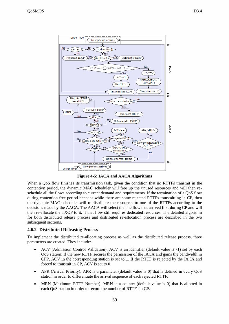
QoSMOS D3.4
39
Figure 4-5: IACA and AACA Algorithms
When a QoS flow finishes its transmission task, given the condition that no RTTFs transmit in the
contention period, the dynamic MAC scheduler will free up the unused resources and will then re-
schedule all the flows according to current demand and requirements. If the termination of a QoS flow
during contention free period happens while there are some rejected RTTFs transmitting in CP, then
the dynamic MAC scheduler will re-distribute the resources to one of the RTTFs according to the
decisions made by the AACA. The AACA will select the one flow that arrived first during CP and will
then re-allocate the TXOP to it, if that flow still requires dedicated resources. The detailed algorithm
for both distributed release process and distributed re-allocation process are described in the two
subsequent sections.
4.6.2 Distributed Releasing Process
To implement the distributed re-allocating process as well as the distributed release process, three
parameters are created. They include:
ACV (Admission Control Validation): ACV is an identifier (default value is -1) set by each
QoS station. If the new RTTF secures the permission of the IACA and gains the bandwidth in
CFP, ACV in the corresponding station is set to 1. If the RTTF is rejected by the IACA and
forced to transmit in CP, ACV is set to 0.
APR (Arrival Priority): APR is a parameter (default value is 0) that is defined in every QoS
station in order to differentiate the arrival sequence of each rejected RTTF.
MRN (Maximum RTTF Number): MRN is a counter (default value is 0) that is allotted in
each QoS station in order to record the number of RTTFs in CP.
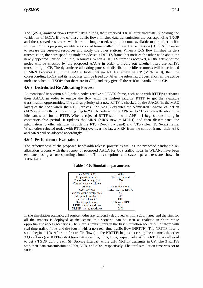
QoSMOS D3.4
40
The QoS guaranteed flows transmit data during their reserved TXOP after successfully passing the
validation of IACA. If one of these traffic flows finishes data transmission, the corresponding TXOP
and the reserved resources, which are no longer used, should become available to the other traffic
sources. For this purpose, we utilize a control frame, called DELete Traffic Session (DELTS), in order
to release the reserved resources and notify the other stations. When a QoS flow finishes its data
transmission, the corresponding node broadcasts a DELTS frame that notifies the other node about the
newly appeared unused (i.e. idle) resources. When a DELTS frame is received, all the active source
nodes will be checked by the proposed AACA in order to figure out whether there are RTTFs
transmitting in CP. The dynamic re-allocating process to distribute the idle resources will be activated
if MRN becomes 0.. If the AACA finds that no RTTFs remain in CP (MRN = 0), then the
corresponding TXOP and its resources will be freed up. After the releasing process ends, all the active
nodes re-schedule TXOPs that there are in CFP, and they give all the residual bandwidth to CP.
4.6.3 Distributed Re-Allocating Process
As mentioned in section 4.6.2, when nodes receive a DELTS frame, each node with RTTF(s) activates
their AACA in order to enable the flow with the highest priority RTTF to get the available
transmission opportunities. The arrival priority of a new RTTF is checked by the AACA (in the MAC
layer) of the node where the RTTF arrives. The AACA executes the Admission Control Validation
(ACV) and sets the corresponding flag to “0”. A node with the APR set to “1” can directly obtain the
idle bandwidth for its RTTF. When a rejected RTTF station with APR = 1 begins transmitting in
contention free period, it updates the MRN (MRN new = MRN1) and then disseminates the
information to other stations through the RTS (Ready To Send) and CTS (Clear To Send) frame.
When other rejected nodes with RTTF(s) overhear the latest MRN from the control frame, their APR
and MRN will be adopted accordingly.
4.6.4 Performance Evaluation
The effectiveness of the proposed bandwidth release process as well as the proposed bandwidth re-
allocation process with the support of proposed AACA for QoS traffic flows in WLANs have been
evaluated using a corresponding simulator. The assumptions and system parameters are shown in
Table 4-10
Table 4-10: Simulation parameters
In the simulation scenario, all source nodes are randomly deployed within a 200m area and the sink for
all the senders is deployed at the centre, this scenario can be seen as realistic in short range
opportunistic access scenarios. There are 4 transmitters in the first simulation scenario 3 of them with
real-time traffic flows and the fourth with a non-real-time traffic flow (NRTTF). The NRTTF flow is
set to begin at 10s. After the first traffic flow (i.e. the NRTTF) begins accessing the channel, the other
3 QoS flows (i.e. RTTFs) start transmitting at 50s, 100s, 150s, respectively. All the RTTFs are allowed
to get a TXOP during each SI (Service Interval) while only NRTTF transmits in CP. The 3 RTTFs
stop their data transmission at 250s, 300s, and 350s, respectively. The total simulation time was set to
500s.
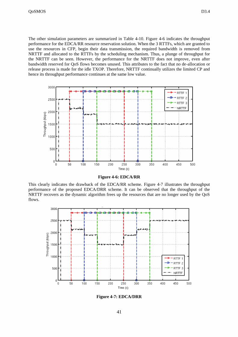
QoSMOS D3.4
41
The other simulation parameters are summarized in Table 4-10. Figure 4-6 indicates the throughput
performance for the EDCA/RR resource reservation solution. When the 3 RTTFs, which are granted to
use the resources in CFP, begin their data transmission, the required bandwidth is removed from
NRTTF and allocated to the RTTFs by the scheduling mechanism. Thus, a plunge of throughput for
the NRTTF can be seen. However, the performance for the NRTTF does not improve, even after
bandwidth reserved for QoS flows becomes unused. This attributes to the fact that no de-allocation or
release process is made for the idle TXOP. Therefore, NRTTF continually utilizes the limited CP and
hence its throughput performance continues at the same low value.
Figure 4-6: EDCA/RR
This clearly indicates the drawback of the EDCA/RR scheme. Figure 4-7 illustrates the throughput
performance of the proposed EDCA/DRR scheme. It can be observed that the throughput of the
NRTTF recovers as the dynamic algorithm frees up the resources that are no longer used by the QoS
flows.
Figure 4-7: EDCA/DRR
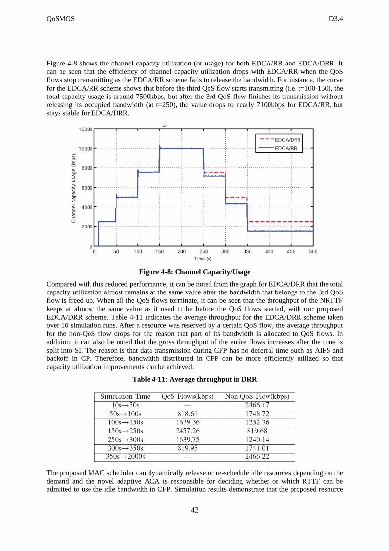
QoSMOS D3.4
42
Figure 4-8 shows the channel capacity utilization (or usage) for both EDCA/RR and EDCA/DRR. It
can be seen that the efficiency of channel capacity utilization drops with EDCA/RR when the QoS
flows stop transmitting as the EDCA/RR scheme fails to release the bandwidth. For instance, the curve
for the EDCA/RR scheme shows that before the third QoS flow starts transmitting (i.e. t=100-150), the
total capacity usage is around 7500kbps, but after the 3rd QoS flow finishes its transmission without
releasing its occupied bandwidth (at t=250), the value drops to nearly 7100kbps for EDCA/RR, but
stays stable for EDCA/DRR.
Figure 4-8: Channel Capacity/Usage
Compared with this reduced performance, it can be noted from the graph for EDCA/DRR that the total
capacity utilization almost remains at the same value after the bandwidth that belongs to the 3rd QoS
flow is freed up. When all the QoS flows terminate, it can be seen that the throughput of the NRTTF
keeps at almost the same value as it used to be before the QoS flows started, with our proposed
EDCA/DRR scheme. Table 4-11 indicates the average throughput for the EDCA/DRR scheme taken
over 10 simulation runs. After a resource was reserved by a certain QoS flow, the average throughput
for the non-QoS flow drops for the reason that part of its bandwidth is allocated to QoS flows. In
addition, it can also be noted that the gross throughput of the entire flows increases after the time is
split into SI. The reason is that data transmission during CFP has no deferral time such as AIFS and
backoff in CP. Therefore, bandwidth distributed in CFP can be more efficiently utilized so that
capacity utilization improvements can be achieved.
Table 4-11: Average throughput in DRR
The proposed MAC scheduler can dynamically release or re-schedule idle resources depending on the
demand and the novel adaptive ACA is responsible for deciding whether or which RTTF can be
admitted to use the idle bandwidth in CFP. Simulation results demonstrate that the proposed resource
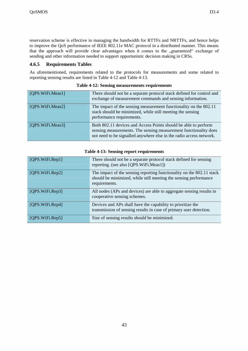
QoSMOS D3.4
43
reservation scheme is effective in managing the bandwidth for RTTFs and NRTTFs, and hence helps
to improve the QoS performance of IEEE 802.11e MAC protocol in a distributed manner. This means
that the approach will provide clear advantages when it comes to the „guaranteed“ exchange of
sending and other information needed to support opportunistic decision making in CRSs.
4.6.5 Requirements Tables
As aforementioned, requirements related to the protocols for measurements and some related to
reporting sensing results are listed in Table 4-12 and Table 4-13.
Table 4-12: Sensing measurements requirements
[QPS.WiFi.Meas1] There should not be a separate protocol stack defined for control and
exchange of measurement commands and sensing information.
[QPS.WiFi.Meas2] The impact of the sensing measurement functionality on the 802.11
stack should be minimized, while still meeting the sensing
performance requirements.
[QPS.WiFi.Meas3] Both 802.11 devices and Access Points should be able to perform
sensing measurements. The sensing measurement functionality does
not need to be signalled anywhere else in the radio access network.
Table 4-13: Sensing report requirements
[QPS.WiFi.Rep1] There should not be a separate protocol stack defined for sensing
reporting. (see also [QPS.WiFi.Meas1])
[QPS.WiFi.Rep2] The impact of the sensing reporting functionality on the 802.11 stack
should be minimized, while still meeting the sensing performance
requirements.
[QPS.WiFi.Rep3] All nodes (APs and devices) are able to aggregate sensing results in
cooperative sensing schemes.
[QPS.WiFi.Rep4] Devices and APs shall have the capability to prioritize the
transmission of sensing results in case of primary user detection.
[QPS.WiFi.Rep5] Size of sensing results should be minimized.
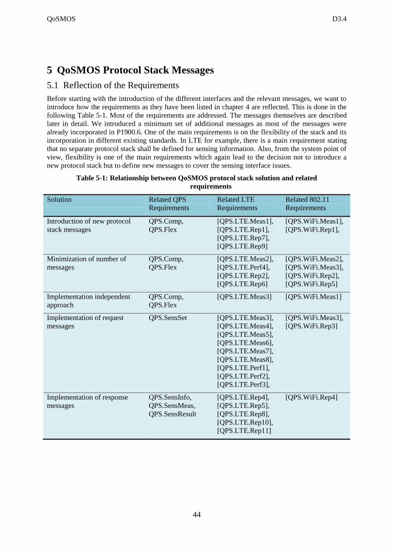
QoSMOS D3.4
44
5 QoSMOS Protocol Stack Messages
5.1 Reflection of the Requirements
Before starting with the introduction of the different interfaces and the relevant messages, we want to
introduce how the requirements as they have been listed in chapter 4 are reflected. This is done in the
following Table 5-1. Most of the requirements are addressed. The messages themselves are described
later in detail. We introduced a minimum set of additional messages as most of the messages were
already incorporated in P1900.6. One of the main requirements is on the flexibility of the stack and its
incorporation in different existing standards. In LTE for example, there is a main requirement stating
that no separate protocol stack shall be defined for sensing information. Also, from the system point of
view, flexibility is one of the main requirements which again lead to the decision not to introduce a
new protocol stack but to define new messages to cover the sensing interface issues.
Table 5-1: Relationship between QoSMOS protocol stack solution and related
requirements
Solution Related QPS
Requirements
Related LTE
Requirements
Related 802.11
Requirements
Introduction of new protocol
stack messages
QPS.Comp,
QPS.Flex
[QPS.LTE.Meas1],
[QPS.LTE.Rep1],
[QPS.LTE.Rep7],
[QPS.LTE.Rep9]
[QPS.WiFi.Meas1],
[QPS.WiFi.Rep1],
Minimization of number of
messages
QPS.Comp,
QPS.Flex
[QPS.LTE.Meas2],
[QPS.LTE.Perf4],
[QPS.LTE.Rep2],
[QPS.LTE.Rep6]
[QPS.WiFi.Meas2],
[QPS.WiFi.Meas3],
[QPS.WiFi.Rep2],
[QPS.WiFi.Rep5]
Implementation independent
approach
QPS.Comp,
QPS.Flex
[QPS.LTE.Meas3] [QPS.WiFi.Meas1]
Implementation of request
messages
QPS.SensSet [QPS.LTE.Meas3],
[QPS.LTE.Meas4],
[QPS.LTE.Meas5],
[QPS.LTE.Meas6],
[QPS.LTE.Meas7],
[QPS.LTE.Meas8],
[QPS.LTE.Perf1],
[QPS.LTE.Perf2],
[QPS.LTE.Perf3],
[QPS.WiFi.Meas3],
[QPS.WiFi.Rep3]
Implementation of response
messages
QPS.SensInfo,
QPS.SensMeas,
QPS.SensResult
[QPS.LTE.Rep4],
[QPS.LTE.Rep5],
[QPS.LTE.Rep8],
[QPS.LTE.Rep10],
[QPS.LTE.Rep11]
[QPS.WiFi.Rep4]
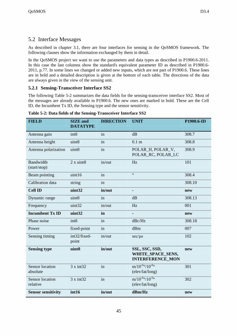
QoSMOS D3.4
45
5.2 Interface Messages
As described in chapter 3.1, there are four interfaces for sensing in the QoSMOS framework. The
following clauses show the information exchanged by them in detail.
In the QoSMOS project we want to use the parameters and data types as described in P1900.6-2011.
In this case the last columns show the standard's equivalent parameter ID as described in P1900.6-
2011, p.77. In some lines we changed or added new inputs, which are not part of P1900.6. These lines
are in bold and a detailed description is given at the bottom of each table. The directions of the data
are always given in the view of the sensing unit.
5.2.1 Sensing-Transceiver Interface SS2
The following Table 5-2 summarizes the data fields for the sensing-transceiver interface SS2. Most of
the messages are already available in P1900.6. The new ones are marked in bold. These are the Cell
ID, the Incumbent Tx ID, the Sensing type and the sensor sensitivity.
Table 5-2: Data fields of the Sensing-Transceiver Interface SS2
FIELD SIZE and
DATATYPE
DIRECTION UNIT P1900.6-ID
Antenna gain int8 in dB 308.7
Antenna height uint8 in 0.1 m 308.8
Antenna polarization uint8 in POLAR_H, POLAR_V,
POLAR_RC, POLAR_LC
308.9
Bandwidth
(start/stop)
2 x uint8 in/out Hz 101
Beam pointing uint16 in ° 308.4
Calibration data string in 308.10
Cell ID uint32 in/out - new
Dynamic range uint8 in dB 308.13
Frequency uint32 in/out Hz 001
Incumbent Tx ID uint32 in - new
Phase noise int8 in dBc/Hz 308.18
Power fixed-point in dBm 007
Sensing timing int32/fixed-
point
in/out sec/μs 102
Sensing type uint8 in/out SSL, SSC, SSD,
WHITE_SPACE_SENS,
INTERFERENCE_MON
new
Sensor location
absolute
3 x int32 in m/10-6
°/10-6
°
(elev/lat/long)
301
Sensor location
relative
3 x int32 in m/10-6
°/10-6
°
(elev/lat/long)
302
Sensor sensitivity int16 in/out dBm/Hz new
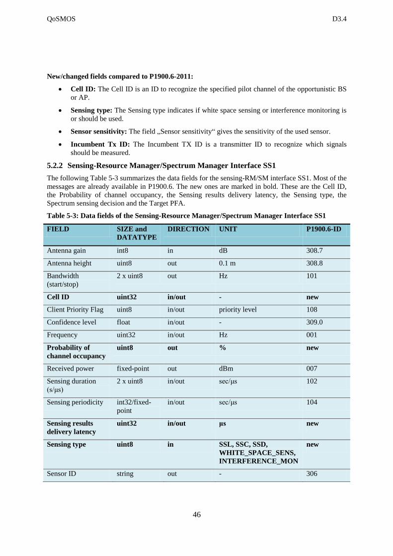
QoSMOS D3.4
46
New/changed fields compared to P1900.6-2011:
Cell ID: The Cell ID is an ID to recognize the specified pilot channel of the opportunistic BS
or AP.
Sensing type: The Sensing type indicates if white space sensing or interference monitoring is
or should be used.
Sensor sensitivity: The field „Sensor sensitivity“ gives the sensitivity of the used sensor.
Incumbent Tx ID: The Incumbent TX ID is a transmitter ID to recognize which signals
should be measured.
5.2.2 Sensing-Resource Manager/Spectrum Manager Interface SS1
The following Table 5-3 summarizes the data fields for the sensing-RM/SM interface SS1. Most of the
messages are already available in P1900.6. The new ones are marked in bold. These are the Cell ID,
the Probability of channel occupancy, the Sensing results delivery latency, the Sensing type, the
Spectrum sensing decision and the Target PFA.
Table 5-3: Data fields of the Sensing-Resource Manager/Spectrum Manager Interface SS1
FIELD SIZE and
DATATYPE
DIRECTION UNIT P1900.6-ID
Antenna gain int8 in dB 308.7
Antenna height uint8 out 0.1 m 308.8
Bandwidth
(start/stop)
2 x uint8 out Hz 101
Cell ID uint32 in/out - new
Client Priority Flag uint8 in/out priority level 108
Confidence level float in/out - 309.0
Frequency uint32 in/out Hz 001
Probability of
channel occupancy
uint8 out % new
Received power fixed-point out dBm 007
Sensing duration
(s/μs)
2 x uint8 in/out sec/μs 102
Sensing periodicity int32/fixed-
point
in/out sec/μs 104
Sensing results
delivery latency
uint32 in/out μs new
Sensing type uint8 in SSL, SSC, SSD,
WHITE_SPACE_SENS,
INTERFERENCE_MON
new
Sensor ID string out - 306
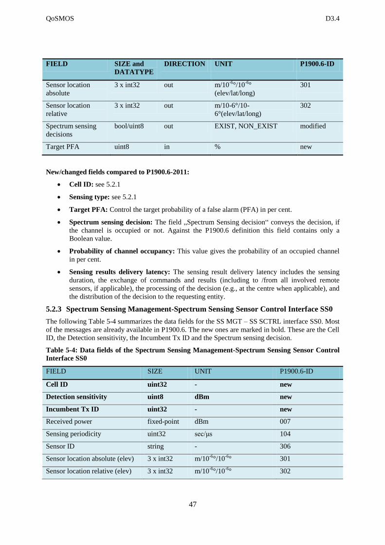
QoSMOS D3.4
47
FIELD SIZE and
DATATYPE
DIRECTION UNIT P1900.6-ID
Sensor location
absolute
3 x int32 out m/10-6
°/10-6
°
(elev/lat/long)
301
Sensor location
relative
3 x int32 out m/10-6°/10-
6°(elev/lat/long)
302
Spectrum sensing
decisions
bool/uint8 out EXIST, NON_EXIST modified
Target PFA uint8 in % new
New/changed fields compared to P1900.6-2011:
Cell ID: see 5.2.1
Sensing type: see 5.2.1
Target PFA: Control the target probability of a false alarm (PFA) in per cent.
Spectrum sensing decision: The field „Spectrum Sensing decision“ conveys the decision, if
the channel is occupied or not. Against the P1900.6 definition this field contains only a
Boolean value.
Probability of channel occupancy: This value gives the probability of an occupied channel
in per cent.
Sensing results delivery latency: The sensing result delivery latency includes the sensing
duration, the exchange of commands and results (including to /from all involved remote
sensors, if applicable), the processing of the decision (e.g., at the centre when applicable), and
the distribution of the decision to the requesting entity.
5.2.3 Spectrum Sensing Management-Spectrum Sensing Sensor Control Interface SS0
The following Table 5-4 summarizes the data fields for the SS MGT – SS SCTRL interface SS0. Most
of the messages are already available in P1900.6. The new ones are marked in bold. These are the Cell
ID, the Detection sensitivity, the Incumbent Tx ID and the Spectrum sensing decision.
Table 5-4: Data fields of the Spectrum Sensing Management-Spectrum Sensing Sensor Control
Interface SS0
FIELD SIZE UNIT P1900.6-ID
Cell ID uint32 - new
Detection sensitivity uint8 dBm new
Incumbent Tx ID uint32 - new
Received power fixed-point dBm 007
Sensing periodicity uint32 sec/μs 104
Sensor ID string - 306
Sensor location absolute (elev) 3 x int32 m/10-6
°/10-6
° 301
Sensor location relative (elev) 3 x int32 m/10-6
°/10-6
° 302
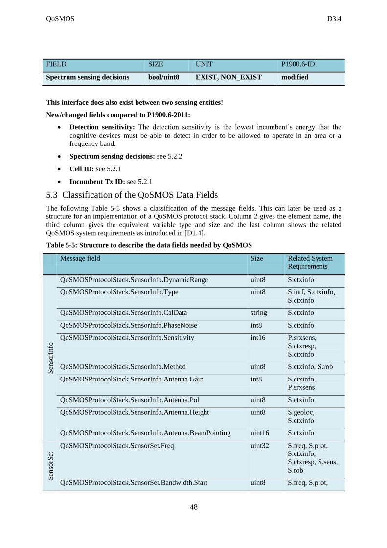
QoSMOS D3.4
48
FIELD SIZE UNIT P1900.6-ID
Spectrum sensing decisions bool/uint8 EXIST, NON_EXIST modified
This interface does also exist between two sensing entities!
New/changed fields compared to P1900.6-2011:
Detection sensitivity: The detection sensitivity is the lowest incumbent’s energy that the
cognitive devices must be able to detect in order to be allowed to operate in an area or a
frequency band.
Spectrum sensing decisions: see 5.2.2
Cell ID: see 5.2.1
Incumbent Tx ID: see 5.2.1
5.3 Classification of the QoSMOS Data Fields
The following Table 5-5 shows a classification of the message fields. This can later be used as a
structure for an implementation of a QoSMOS protocol stack. Column 2 gives the element name, the
third column gives the equivalent variable type and size and the last column shows the related
QoSMOS system requirements as introduced in [D1.4].
Table 5-5: Structure to describe the data fields needed by QoSMOS
Message field Size Related System
Requirements
Sen
sorI
nfo
QoSMOSProtocolStack.SensorInfo.DynamicRange uint8 S.ctxinfo
QoSMOSProtocolStack.SensorInfo.Type uint8 S.intf, S.ctxinfo,
S.ctxinfo
QoSMOSProtocolStack.SensorInfo.CalData string S.ctxinfo
QoSMOSProtocolStack.SensorInfo.PhaseNoise int8 S.ctxinfo
QoSMOSProtocolStack.SensorInfo.Sensitivity int16 P.srxsens,
S.ctxresp,
S.ctxinfo
QoSMOSProtocolStack.SensorInfo.Method uint8 S.ctxinfo, S.rob
QoSMOSProtocolStack.SensorInfo.Antenna.Gain int8 S.ctxinfo,
P.srxsens
QoSMOSProtocolStack.SensorInfo.Antenna.Pol uint8 S.ctxinfo
QoSMOSProtocolStack.SensorInfo.Antenna.Height uint8 S.geoloc,
S.ctxinfo
QoSMOSProtocolStack.SensorInfo.Antenna.BeamPointing uint16 S.ctxinfo
Sen
sorS
et
QoSMOSProtocolStack.SensorSet.Freq uint32 S.freq, S.prot,
S.ctxinfo,
S.ctxresp, S.sens,
S.rob
QoSMOSProtocolStack.SensorSet.Bandwidth.Start uint8 S.freq, S.prot,
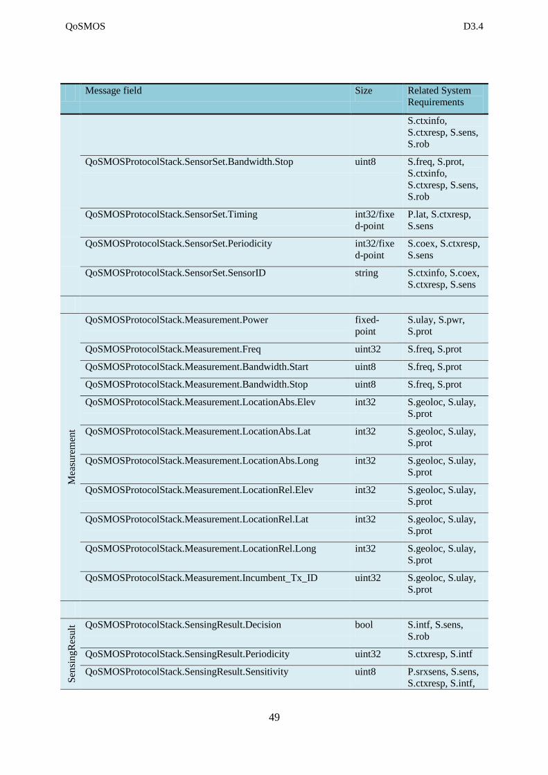
QoSMOS D3.4
49
Message field Size Related System
Requirements
S.ctxinfo,
S.ctxresp, S.sens,
S.rob
QoSMOSProtocolStack.SensorSet.Bandwidth.Stop uint8 S.freq, S.prot,
S.ctxinfo,
S.ctxresp, S.sens,
S.rob
QoSMOSProtocolStack.SensorSet.Timing int32/fixe
d-point
P.lat, S.ctxresp,
S.sens
QoSMOSProtocolStack.SensorSet.Periodicity int32/fixe
d-point
S.coex, S.ctxresp,
S.sens
QoSMOSProtocolStack.SensorSet.SensorID string S.ctxinfo, S.coex,
S.ctxresp, S.sens
Mea
sure
men
t
QoSMOSProtocolStack.Measurement.Power fixed-
point
S.ulay, S.pwr,
S.prot
QoSMOSProtocolStack.Measurement.Freq uint32 S.freq, S.prot
QoSMOSProtocolStack.Measurement.Bandwidth.Start uint8 S.freq, S.prot
QoSMOSProtocolStack.Measurement.Bandwidth.Stop uint8 S.freq, S.prot
QoSMOSProtocolStack.Measurement.LocationAbs.Elev int32 S.geoloc, S.ulay,
S.prot
QoSMOSProtocolStack.Measurement.LocationAbs.Lat int32 S.geoloc, S.ulay,
S.prot
QoSMOSProtocolStack.Measurement.LocationAbs.Long int32 S.geoloc, S.ulay,
S.prot
QoSMOSProtocolStack.Measurement.LocationRel.Elev int32 S.geoloc, S.ulay,
S.prot
QoSMOSProtocolStack.Measurement.LocationRel.Lat int32 S.geoloc, S.ulay,
S.prot
QoSMOSProtocolStack.Measurement.LocationRel.Long int32 S.geoloc, S.ulay,
S.prot
QoSMOSProtocolStack.Measurement.Incumbent_Tx_ID uint32 S.geoloc, S.ulay,
S.prot
Sen
sin
gR
esult
QoSMOSProtocolStack.SensingResult.Decision bool S.intf, S.sens,
S.rob
QoSMOSProtocolStack.SensingResult.Periodicity uint32 S.ctxresp, S.intf
QoSMOSProtocolStack.SensingResult.Sensitivity uint8 P.srxsens, S.sens,
S.ctxresp, S.intf,
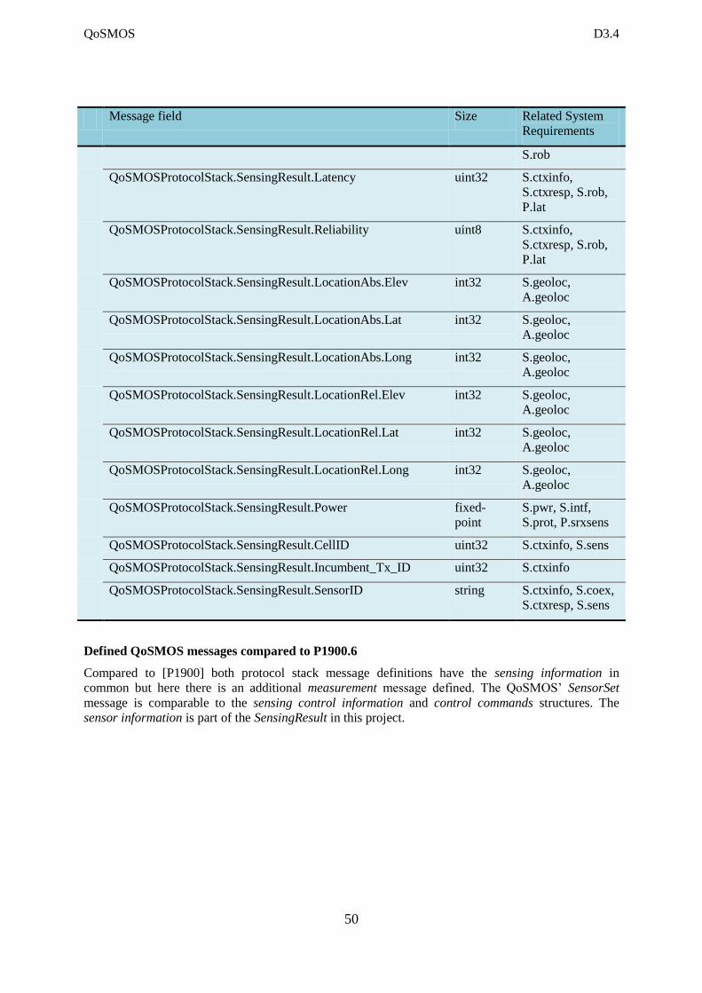
QoSMOS D3.4
50
Message field Size Related System
Requirements
S.rob
QoSMOSProtocolStack.SensingResult.Latency uint32 S.ctxinfo,
S.ctxresp, S.rob,
P.lat
QoSMOSProtocolStack.SensingResult.Reliability uint8 S.ctxinfo,
S.ctxresp, S.rob,
P.lat
QoSMOSProtocolStack.SensingResult.LocationAbs.Elev int32 S.geoloc,
A.geoloc
QoSMOSProtocolStack.SensingResult.LocationAbs.Lat int32 S.geoloc,
A.geoloc
QoSMOSProtocolStack.SensingResult.LocationAbs.Long int32 S.geoloc,
A.geoloc
QoSMOSProtocolStack.SensingResult.LocationRel.Elev int32 S.geoloc,
A.geoloc
QoSMOSProtocolStack.SensingResult.LocationRel.Lat int32 S.geoloc,
A.geoloc
QoSMOSProtocolStack.SensingResult.LocationRel.Long int32 S.geoloc,
A.geoloc
QoSMOSProtocolStack.SensingResult.Power fixed-
point
S.pwr, S.intf,
S.prot, P.srxsens
QoSMOSProtocolStack.SensingResult.CellID uint32 S.ctxinfo, S.sens
QoSMOSProtocolStack.SensingResult.Incumbent_Tx_ID uint32 S.ctxinfo
QoSMOSProtocolStack.SensingResult.SensorID string S.ctxinfo, S.coex,
S.ctxresp, S.sens
Defined QoSMOS messages compared to P1900.6
Compared to [P1900] both protocol stack message definitions have the sensing information in
common but here there is an additional measurement message defined. The QoSMOS’ SensorSet
message is comparable to the sensing control information and control commands structures. The
sensor information is part of the SensingResult in this project.
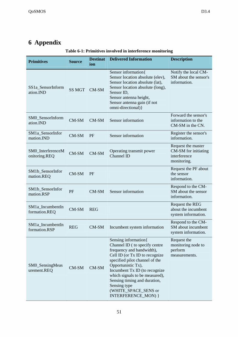
QoSMOS D3.4
51
6 Appendix
Table 6-1: Primitives involved in interference monitoring
Primitives Source Destinat
ion
Delivered Information Description
SS1a_SensorInform
ation.IND SS MGT CM-SM
Sensor information{
Sensor location absolute (elev),
Sensor location absolute (lat),
Sensor location absolute (long),
Sensor ID,
Sensor antenna height,
Sensor antenna gain (if not
omni-directional)}
Notify the local CM-
SM about the sensor's
information.
SM0_SensorInform
ation.IND CM-SM CM-SM Sensor information
Forward the sensor's
information to the
CM-SM in the CN.
SM1a_SensorInfor
mation.IND CM-SM PF Sensor information
Register the sensor's
information.
SM0_InterferenceM
onitoring.REQ CM-SM CM-SM
Operating transmit power
Channel ID
Request the master
CM-SM for initiating
interference
monitoring.
SM1b_SensorInfor
mation.REQ CM-SM PF
Request the PF about
the sensor
information.
SM1b_SensorInfor
mation.RSP PF CM-SM Sensor information
Respond to the CM-
SM about the sensor
information.
SM1a_IncumbentIn
formation.REQ CM-SM REG
Request the REG
about the incumbent
system information.
SM1a_IncumbentIn
formation.RSP REG CM-SM Incumbent system information
Respond to the CM-
SM about incumbent
system information.
SM0_SensingMeas
urement.REQ CM-SM CM-SM
Sensing information{
Channel ID ( to specify centre
frequency and bandwidth),
Cell ID (or Tx ID to recognize
specified pilot channel of the
Opportunistic Tx),
Incumbent Tx ID (to recognize
which signals to be measured),
Sensing timing and duration,
Sensing type
(WHITE_SPACE_SENS or
INTERFERENCE_MON) }
Request the
monitoring node to
perform
measurements.
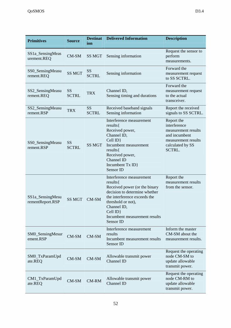
QoSMOS D3.4
52
Primitives Source Destinat
ion
Delivered Information Description
SS1a_SensingMeas
urement.REQ CM-SM SS MGT Sensing information
Request the sensor to
perform
measurements.
SS0_SensingMeasu
rement.REQ SS MGT
SS
SCTRL Sensing information
Forward the
measurement request
to SS SCTRL.
SS2_SensingMeasu
rement.REQ
SS
SCTRL TRX
Channel ID,
Sensing timing and durations
Forward the
measurement request
to the actual
transceiver.
SS2_SensingMeasu
rement.RSP TRX
SS
SCTRL
Received baseband signals
Sensing information
Report the received
signals to SS SCTRL.
SS0_SensingMeasu
rement.RSP
SS
SCTRL SS MGT
Interference measurement
results{
Received power,
Channel ID,
Cell ID}
Incumbent measurement
results{
Received power,
Channel ID
Incumbent Tx ID}
Sensor ID
Report the
interference
measurement results
and incumbent
measurement results
calculated by SS
SCTRL.
SS1a_SensingMesu
rementReport.RSP SS MGT CM-SM
Interference measurement
results{
Received power (or the binary
decision to determine whether
the interference exceeds the
threshold or not),
Channel ID,
Cell ID}
Incumbent measurement results
Sensor ID
Report the
measurement results
from the sensor.
SM0_SensingMesur
ement.RSP CM-SM CM-SM
Interference measurement
results
Incumbent measurement results
Sensor ID
Inform the master
CM-SM about the
measurement results.
SM0_TxParamUpd
ate.REQ CM-SM CM-SM
Allowable transmit power
Channel ID
Request the operating
node CM-SM to
update allowable
transmit power.
CM1_TxParamUpd
ate.REQ CM-SM CM-RM
Allowable transmit power
Channel ID
Request the operating
node CM-RM to
update allowable
transmit power.
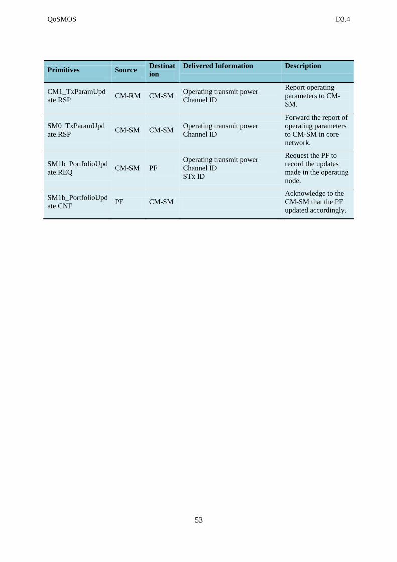
QoSMOS D3.4
53
Primitives Source Destinat
ion
Delivered Information Description
CM1_TxParamUpd
ate.RSP CM-RM CM-SM
Operating transmit power
Channel ID
Report operating
parameters to CM-
SM.
SM0_TxParamUpd
ate.RSP CM-SM CM-SM
Operating transmit power
Channel ID
Forward the report of
operating parameters
to CM-SM in core
network.
SM1b_PortfolioUpd
ate.REQ CM-SM PF
Operating transmit power
Channel ID
STx ID
Request the PF to
record the updates
made in the operating
node.
SM1b_PortfolioUpd
ate.CNF PF CM-SM
Acknowledge to the
CM-SM that the PF
updated accordingly.
QoSMOS D3.4
54
7 References
[D1.2] R. MacKenzie; P.-H. Lehne; U. Celentano; M. Ariyoshi; B. Cendón;
A. Medela; “QoSMOS Consolidated Scenarios”, QOSMOS
deliverable D1.2, Dec 2010
[D1.4] P.-H. Lehne, U. Celentano, J. Lehtomäki, D. Noguet, R. Datta, P.
Delahaye, R. Wansch, V. Berg, P. Grønsund, “QoSMOS
consolidated system requirements”, QOSMOS deliverable D1.4,
May 2011
[D2.2] S. Leveil, C. Le Martret; O. Grøndalen; B. Bochow; C. Rosik, V.
Mérat; B. Cendón, J. Herrero, A. Medela; U. Celentano; R. Datta; F.
Noack, C. Lange, J. Gebert; K. Moessner; H. Sugahara, K. Muraoka,
M. Ariyoshi, “System architecture options for the QoSMOS
system“, QoSMOS project deliverable D2.2, Dec 2010
[D2.3] G. Mange; P. Horváth; V. Berg; B. Bochow; R. Robles; M.
Ariyoshi; C. Rosik; O. Grøndalen, P.-H. Lehne; J. Rico, A. Medela;
R. Data; U. Celentano, “System specification and evaluation
criteria“, QoSMOS project deliverable D2.3, Nov 2011
[D3.2] R. Wansch; U. Celentano, J. Lehtomäki, J. Vartiainen; F. Kemeth,
M. Schühler, K. Arshad, X. Yu, P. Navaratnam, K. Moessner; M.
Gautier; M. Ariyoshi, K. Muraoka; P. Delahaye; L. Gonçalves,
“Reference protocol stack for QoSMOS radio environment mapping
and sensing“, QoSMOS project deliverable D3.2, Oct 2010
[D3.3] D. Depierree; K. Muraoka; H. Sugahara; M. Ariyoshi; D. Depierre;
M. Gautier; D. Noguet, J. Vartiainen; J. Lehtomäki; K. Arshad; D.
Panaitopol; L. Gonçalves; A. Gameiro; “Radio Context Acquisition
algorithms – Preliminary version”, QoSMOS project deliverable
D3.3, Feb 2011
[D5.2] G. Mange, P. Horváth, R. Mac Kenzie, K. Briggs, M. Fitch, C.
Rosik, S. Leveil, C. Le Martret, R. Massin, P. Fouillot, A. Sanz, B.
Cendón, A. Medela, J. Rico, K. Arshad, T. Guo, U. Celentano,
“Final framework description, preliminary cognitive manager
structure and first mechanisms for QoS support“, QoSMOS project
deliverable D5.2, 13 Jul 2011.
[D6.2] F. Noack, C. Lange; S. Kawade; B. Bochow; A. Gameiro; H.
Sugahara, K. Muraoka, T. Nakamura, M. Ariyoshi, P. Grønsund; K.
Moessner; U. Celentano, J. Vartiainen, J. Lehtomäki, “Description
of context filtering, aggregation and communication functions of the
spectrum management framework”, QoSMOS project deliverable
D6.2, Apr 2011
[D6.3] I. Karla, F. Noack, C. Lange; A. Gameiro, A. Sousa, R. Samano; U.
Celentano, J. Lehtomäki, J. Vartiainen; M. Ariyoshi, K. Muraoka,
T. Nakamura, H. Sugahara; Y. Ko, K. Moessner; P. Grønsund; P.
Bakki, J. Bitó, L. Csurgai-Horváth; B. Bochow, “Initial description
QoSMOS D3.4
55
of cognitive and opportunistic functions of the spectrum
management framework”, QOSMOS deliverable D6.3 , Oct 2011
[D7.2] B. Cendón, A. Medela, J. Rico, J. Duplicy, D. Tandur, D. Noguet, V.
Berg, P. Delahaye, B. Bochow, C. Ribeiro, J. Quaresma, M.
Schühler, M. Tessema, R. MacKenzie, K. Briggs, “Platform
Architecture Definition (2/2)”, QoSMOS project deliverable D7.2,
Dec 2011
[Celen11] U. Celentano, B. Bochow, C. Lange, F. Noack, J. Herrero, B.
Cendón, O. Grøndalen, V. Mérat, C. Rosik, “Flexible architecture
for spectrum and resource management in the whitespace”, Proc.
Int. Symp. Wireless Personal Multimedia Commun. (WPMC), Brest,
France, 3-7 Oct 2011.
[Gusta05] F. Gustafsson and F. Gunnarsson, “Mobile Positioning Using
Wireless Networks: Possibilities and Fundamental Limitations
Based on Available Wireless Network Measurements”, IEEE Signal
Processing Magazine, Jul 2005
[Küppe05] A. Küpper, Location-Based Services: Fundamentals and Operation,
Wiley 2005
[Layh06] M. Layh, U. Reiser, D. Zimmermann, F. Landstorfer “Positioning of
Mobile Terminals based on Feature Extraction from Channel
Impulse Responses” IEEE Vehicular Technology Conference-Spring
2006
[Levei12] S. Leveil, C. J. Le Martret, H. Anouar; K. Arshad, T. Zahir; J. Bito
U. Celentano; G. Mange; J. Rico, A. Medela, “Resource
management of centrally controlled cognitive radio networks”, Proc.
Future Network & Mobile Summit (FuNeMS), Berlin, Germany, 4-6
Jun 2012
[MacKe11] R. MacKenzie, P.-H. Lehne, U. Celentano, “Identifying scenarios
with high potential for future cognitive radio networks”, Proc.
Future Network & Mobile Summit (FuNeMS), Warszaw, Poland, 15-
17 Jun 2011
[Mange11] G. Mange, C. Rosik, S. Leveil, U. Celentano, O. Durowoju, K.
Arshad, “Cognitive resource management for QoS support in mobile
opportunistic communications”, Proc. Future Network & Mobile
Summit (FuNeMS), Warszaw, Poland, 15-17 Jun 2011.
[Moess11] K. Moessner, H. Harada, C. Sun, Y.D. Alemseged, H. Nguyen Tran ,
D. Noguet, R. Sawai, N. Sato, " Spectrum sensing for cognitive
radio systems: technical aspects and standardization activities of the
IEEE P1900.6 working group", IEEE Communication Magazine,
Vol. 18, pp30-37, Feb 2011
[Murao11] K. Muraoka, H. Sugahara, M. Ariyoshi, “Monitoring-based spectrum
management for expanding opportunities of white space utilization,”
Proc. IEEE International Symposium on New Frontiers in Dynamic
QoSMOS D3.4
56
Spectrum Access Network (DySPAN), May 2011
[Murro11] M. Murroni, R.V. Prasad, P. Marques, B. Bochow, , D. Noguet, C.
Sun, K. Moessner, H. Harada, „IEEE 1900.6: spectrum sensing
interfaces and data structures for dynamic spectrum access and other
advanced radio communication systems standard: technical aspects
and future outlook", IEEE Communication Magazine, Vol. 49,
pp118-127, Dec 2011
[Otsas05] V. Otsason, A. Varshavsky, A. LaMarca, and E. de Lara. “Accurate
GSM indoor localization”. In the Seventh International Conference
on Ubiquitous Computing (UbiComp 2005), Sep 2005
[P1900] K. Moessner, H. Nguyen Tran, C. Sun, B. Bochow, D. Swain, Y. D.
Alemseged, M. Ariyoshi, S. Aust, H. Harada, O. Holland, T. Ito, P.
Marques, M. Murroni, D. Noguet, S. Pollin, V. Prasad, N. Sato, R.
Sawai, A. Yamaguchi, “IEEE Standard for Spectrum Sensing
Interfaces and Data Structures for Dynamic Spectrum Access and
Other Advanced Radio Communication Systems”, IEEE Std
1900.6™-2011, April 2011
[FCC09] FCC. “Unlicensed Operation in the TV Broadcast Bands, Final
Rules [online] URL: http://edocket.access.gpo.gov/2009/pdf/E9-
3279.pdf”
[OFCOM09]. OFCOM. “Digital dividend: cognitive access Consultation on
licence-exempting cognitive devices using interleaved spectrum”,
May 2009
[TS 36.331] 3GPP TS 36.331; 3rd Generation Partnership Project; Technical
Specification Group Radio Access Network; Evolved Universal
Terrestrial Radio Access (E-UTRA); Radio Resource Control
(RRC); Protocol specification (Release 10)
[TS 36.321] 3GPP TS 36.321; 3rd Generation Partnership Project; Technical
Specification Group Radio Access Network; Evolved Universal
Terrestrial Radio Access (E-UTRA); Medium Access Control
(MAC) protocol specification (Release 10)
[TS 36.304] 3GPP TS 36.304; 3rd Generation Partnership Project; Technical
Specification Group Radio Access Network; Evolved Universal
Terrestrial Radio Access (E-UTRA); User Equipment (UE)
procedures in idle mode (Release 10)
[TS 36.314] 3GPP TS 36.314; 3rd Generation Partnership Project; Technical
Specification Group Radio Access Network; Evolved Universal
Terrestrial Radio Access (E-UTRA); Layer 2 – Measurements
(Release 10)