Embed Size (px)
Citation preview

Recording Component (RC-P / RC-I / RC-C)
User Manual
©2015 On-Net Surveillance Systems, Inc.
Contents RC-P / RC-I / RC-C User Manual
2 On-Net Surveillance Systems, Inc.
On-Net Surveillance Systems, Inc.
One Blue Hill Plaza, 7th Floor, PO Box 1555 Pearl River, NY 10965
Phone: (845) 732-7900 | Fax: (845) 732-7999 Web: www.onssi.com
0011062014-1422-RC-PIC_8.6-O4.1.2.182
Legal Notice
This product manual is intended for general information purposes only, and due care has been taken in its preparation.
Any risk arising from the use of this information rests with the recipient, and nothing herein should be construed as constituting any kind of warranty.
© 2002-2015 On-Net Surveillance Systems, Inc. All rights reserved. OnSSI and the ‘Eye’ logo are registered trademarks of On-Net Surveillance Systems, Inc. Ocularis, Ocularis Client, Ocularis Client Lite, Ocularis Video Synopsis, NetEVS, NetDVMS, NetDVR, ProSight, NetGuard, NetGuard-EVS, NetSwitcher, NetMatrix, NetCentral, NetTransact, NetPDA and NetCell are trademarks of On-Net Surveillance Systems, Inc. All other trademarks are property of their respective owners.
On-Net Surveillance Systems, Inc. reserves the right to change product specifications without prior notice. Patents Applied For in the U.S. and Abroad

RC-P / RC-I / RC-C User Manual Contents
On-Net Surveillance Systems, Inc. 3
Contents BEFORE YOU START.................................................................................................................................... 7
DOCUMENTATION.......................................................................................................................................... 7 MINIMUM SYSTEM REQUIREMENTS .................................................................................................................. 7 ADMINISTRATOR RIGHTS................................................................................................................................ 7 IMPORTANT PORT NUMBERS........................................................................................................................... 7 VIRUS SCANNING .......................................................................................................................................... 8 TIME SERVER USE RECOMMENDED.................................................................................................................. 8 ABOUT HANDLING DAYLIGHT SAVING TIME ........................................................................................................ 8
AUTOMATIC CONFIGURATION WIZARD: CONTINUE AFTER SCAN........................................................ 9
INSTALL AND UPGRADE............................................................................................................................ 10 INSTALL YOUR SURVEILLANCE SERVER SOFTWARE.......................................................................................... 10 UPGRADE .................................................................................................................................................. 10
About upgrading ................................................................................................................................. 10 Upgrade from a previous version ....................................................................................................... 10
VIDEO DEVICE DRIVERS ............................................................................................................................... 11 REMOVE SYSTEM COMPONENTS ................................................................................................................... 11
FIRST TIME USE .......................................................................................................................................... 12 GET YOUR SYSTEM UP AND RUNNING ............................................................................................................ 12 ABOUT SAVING CHANGES TO THE CONFIGURATION.......................................................................................... 13 ABOUT THE BUILT-IN HELP............................................................................................................................ 13 ABOUT RESTARTING SERVICES ..................................................................................................................... 13
LICENSES..................................................................................................................................................... 15 ABOUT LICENSES ........................................................................................................................................ 15 OVERVIEW OF LICENSE INFORMATION............................................................................................................ 15 ABOUT REPLACING CAMERAS ....................................................................................................................... 16 ABOUT ACTIVATING LICENSES....................................................................................................................... 16
About activating licenses after grace period ....................................................................................... 17 Change SLC....................................................................................................................................... 17
SETTINGS..................................................................................................................................................... 18 ABOUT AUTOMATIC DEVICE DISCOVERY ......................................................................................................... 18 CHANGE DEFAULT FILE PATHS ...................................................................................................................... 18 OPTIONS.................................................................................................................................................... 19
General............................................................................................................................................... 19 User Interface..................................................................................................................................... 20 Default File Paths ............................................................................................................................... 20
GETTING STARTED..................................................................................................................................... 21 ABOUT THE GETTING STARTED PAGE ............................................................................................................ 21 AUTOMATIC CONFIGURATION WIZARD ............................................................................................................ 21
Automatic configuration wizard: First page......................................................................................... 21 Automatic configuration wizard: Scanning options ............................................................................. 21 Automatic configuration wizard: Select hardware manufacturers to scan for ..................................... 21 Automatic configuration wizard: Scanning for hardware devices........................................................ 21
ADD HARDWARE WIZARD.............................................................................................................................. 22 Express .............................................................................................................................................. 22 Manual................................................................................................................................................ 23
CONFIGURE STORAGE WIZARD ..................................................................................................................... 26 Configure storage: Video settings and preview .................................................................................. 26 Configure storage: Online schedule ................................................................................................... 26 Live and recording settings Motion-JPEG cameras............................................................................ 27
Contents RC-P / RC-I / RC-C User Manual
4 On-Net Surveillance Systems, Inc.
Live and recording settings MPEG cameras ...................................................................................... 28 Drive selection.................................................................................................................................... 30 Recording and archiving settings ....................................................................................................... 31
ADJUST MOTION DETECTION WIZARD............................................................................................................. 32 Exclude regions.................................................................................................................................. 33 Motion Detection ................................................................................................................................ 33
MANAGE USER ACCESS WIZARD.................................................................................................................... 34 Basic and Windows users .................................................................................................................. 35 Access summary ................................................................................................................................ 35
ADVANCED CONFIGURATION................................................................................................................... 36 HARDWARE DEVICES................................................................................................................................... 36
About hardware devices..................................................................................................................... 36 About microphones ............................................................................................................................ 36 About speakers .................................................................................................................................. 36 About recording audio ........................................................................................................................ 36 About dedicated input/output devices................................................................................................. 37 About replacing hardware devices ..................................................................................................... 37 Configure hardware devices............................................................................................................... 37 Delete hardware devices .................................................................................................................... 38 Replace Hardware Device wizard ...................................................................................................... 38 Hardware properties........................................................................................................................... 40 Speaker properties ............................................................................................................................. 42
CAMERAS AND STORAGE INFORMATION ......................................................................................................... 42 About video and recording configuration ............................................................................................ 42 About database resizing ..................................................................................................................... 43 About motion detection settings ......................................................................................................... 43 About motion detection and PTZ cameras ......................................................................................... 43 Configure camera-specific schedules................................................................................................. 44 Configure when cameras should do what........................................................................................... 45 Configure motion detection................................................................................................................. 45 Disable or delete cameras.................................................................................................................. 46 Move PTZ type 1 and 3 to required positions ..................................................................................... 46 Recording and storage properties ...................................................................................................... 46 Camera properties.............................................................................................................................. 60
MICROPHONES ........................................................................................................................................... 74 About microphones ............................................................................................................................ 74 Configure microphones or speakers................................................................................................... 74 Show or hide microphones or speakers ............................................................................................. 74 Microphone (properties) ..................................................................................................................... 74
EVENTS AND OUTPUT .................................................................................................................................. 75 About input and output ....................................................................................................................... 75 About events and output .................................................................................................................... 75 Overview of events and output ........................................................................................................... 76 Add a hardware input event................................................................................................................ 77 Add a hardware output ....................................................................................................................... 78 Add a manual event ........................................................................................................................... 78 Add a generic event ........................................................................................................................... 79 Add a timer event ............................................................................................................................... 79 Configure hardware output on event .................................................................................................. 79 Configure general event handling....................................................................................................... 80 General event properties .................................................................................................................... 80 Events and output properties.............................................................................................................. 80
SCHEDULING AND ARCHIVING ....................................................................................................................... 87 About scheduling................................................................................................................................ 87 About archiving................................................................................................................................... 87 Configure general scheduling and archiving....................................................................................... 92 General scheduling properties............................................................................................................ 92 Camera-specific scheduling properties .............................................................................................. 95

RC-P / RC-I / RC-C User Manual Contents
On-Net Surveillance Systems, Inc. 5
NETMATRIX ............................................................................................................................................... 96 About NetMatrix video sharing ........................................................................................................... 96 About NetMatrix-recipients ................................................................................................................. 97 Configure NetMatrix ........................................................................................................................... 97
LOGS ........................................................................................................................................................ 97 About logs .......................................................................................................................................... 97 Configure system, event and audit logging......................................................................................... 99 Log properties .................................................................................................................................... 99
NOTIFICATIONS......................................................................................................................................... 100 About notifications ............................................................................................................................ 100 Email ................................................................................................................................................ 100 SMS ................................................................................................................................................. 103 Scheduling........................................................................................................................................ 105
NETCENTRAL ........................................................................................................................................... 105 About NetCentral.............................................................................................................................. 105 Enable NetCentral ............................................................................................................................ 105 NetCentral properties ....................................................................................................................... 105
SERVER ACCESS....................................................................................................................................... 106 About server access......................................................................................................................... 106 About registered services ................................................................................................................. 106 Configure server access................................................................................................................... 106 Server access properties.................................................................................................................. 107
MASTER/SLAVE........................................................................................................................................ 108 About master and slave.................................................................................................................... 108 Configure master and slave servers................................................................................................. 108 Master/slave properties .................................................................................................................... 109
USERS..................................................................................................................................................... 110 About users ...................................................................................................................................... 110 Add basic users................................................................................................................................ 110 Add Windows users.......................................................................................................................... 111 Add user groups ............................................................................................................................... 111 Configure user and group rights ....................................................................................................... 112 User properties................................................................................................................................. 112
SERVICES ................................................................................................................................................ 115 About services.................................................................................................................................. 115 Start and stop services..................................................................................................................... 116
BACKUP AND RESTORE CONFIGURATION........................................................................................... 117 ABOUT BACKUP AND RESTORE OF CONFIGURATIONS..................................................................................... 117 BACK UP SYSTEM CONFIGURATION.............................................................................................................. 117 RESTORE SYSTEM CONFIGURATION ON THE SAME SERVER ........................................................................... 117 MOVE A RECORDER CONFIGURATION FROM ONE SERVER TO ANOTHER SERVER............................................ 118 EXPORT AND IMPORT MANAGEMENT APPLICATION CONFIGURATION................................................................. 119 IMPORT CHANGES TO CONFIGURATION ........................................................................................................ 120 RESTORE SYSTEM CONFIGURATION FROM A RESTORE POINT ......................................................................... 120
MISCELLANEOUS CONCEPTS AND TASKS........................................................................................... 122 ABOUT PROTECTING RECORDING DATABASES FROM CORRUPTION .................................................................. 122 MONITOR STORAGE SPACE USAGE.............................................................................................................. 122 VIEW VIDEO FROM CAMERAS IN MANAGEMENT APPLICATION.......................................................................... 123
INDEX ......................................................................................................................................................... 124

Before you start RC-P / RC-I / RC-C User Manual
6 On-Net Surveillance Systems, Inc.
Copyright, trademarks and disclaimer
Copyright © 2002-2015 On-Net Surveillance Systems, Inc. All rights reserved.
Trademarks
Microsoft and Windows are registered trademarks of Microsoft Corporation. App Store is a service mark of Apple Inc. Android is a trademark of Google Inc.
All other trademarks mentioned in this document are trademarks of their respective owners.
Disclaimer
This text is intended for general information purposes only, and due care has been taken in its preparation.
Any risk arising from the use of this information rests with the recipient, and nothing herein should be construed as constituting any kind of warranty.
OnSSI reserves the right to make adjustments without prior notification.
All names of people and organizations used in the examples in this text are fictitious. Any resemblance to any actual organization or person, living or dead, is purely coincidental and unintended.
This product may make use of third party software for which specific terms and conditions may apply. When that is the case, you can find more information in the file 3rd_party_software_terms_and_conditions.txt located in your OnSSI surveillance system installation folder.
OnSSI and the ‘Eye’ logo are registered trademarks of On-Net Surveillance Systems, Inc. Ocularis, Ocularis Client, Ocularis Client Lite, Ocularis Video Synopsis, NetEVS, NetDVMS, NetDVR, ProSight, NetGuard, NetGuard-EVS, NetSwitcher, NetMatrix, NetCentral, NetTransact, NetPDA and NetCell are trademarks of On-Net Surveillance Systems, Inc. All other trademarks are property of their respective owners.
(RC-P, RC-I, RC-C v8.6)
Patents Applied For in the U.S. and Abroad
RC-P / RC-I / RC-C User Manual Before you start
On-Net Surveillance Systems, Inc. 7
Before you start
Documentation
This document was prepared to support the RC-C, RC-I and RC-P recording component software products and all efforts were made to point out where the differences in each model occur. If you feel the content of this document is in error, please contact OnSSI Technical Support for verification.
Minimum system requirements
For up-to-date system requirements of all Ocularis components, please visit:
http://www.onssi.com/hardware-recommendations
Administrator rights
When you install the software, it is important that you have administrator rights on the computer that should run the recorder. If you only have standard user rights, you cannot configure the surveillance system.
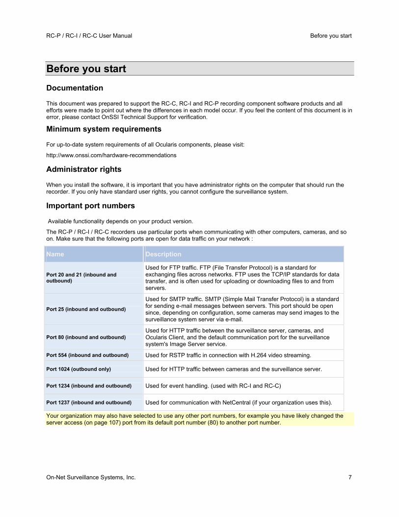
Important port numbers
Available functionality depends on your product version.
The RC-P / RC-I / RC-C recorders use particular ports when communicating with other computers, cameras, and so on. Make sure that the following ports are open for data traffic on your network :
Name Description
Port 20 and 21 (inbound and outbound)
Used for FTP traffic. FTP (File Transfer Protocol) is a standard for exchanging files across networks. FTP uses the TCP/IP standards for data transfer, and is often used for uploading or downloading files to and from servers.
Port 25 (inbound and outbound)
Used for SMTP traffic. SMTP (Simple Mail Transfer Protocol) is a standard for sending e-mail messages between servers. This port should be open since, depending on configuration, some cameras may send images to the surveillance system server via e-mail.
Port 80 (inbound and outbound) Used for HTTP traffic between the surveillance server, cameras, and Ocularis Client, and the default communication port for the surveillance system's Image Server service.
Port 554 (inbound and outbound) Used for RSTP traffic in connection with H.264 video streaming.
Port 1024 (outbound only) Used for HTTP traffic between cameras and the surveillance server.
Port 1234 (inbound and outbound) Used for event handling. (used with RC-I and RC-C)
Port 1237 (inbound and outbound) Used for communication with NetCentral (if your organization uses this).
Your organization may also have selected to use any other port numbers, for example you have likely changed the server access (on page 107) port from its default port number (80) to another port number.
Before you start RC-P / RC-I / RC-C User Manual
8 On-Net Surveillance Systems, Inc.
Virus scanning
Virus scanning uses a considerable amount of system resources on scanning all the data as it is archived or used. The scanning process may temporarily lock each file it scans, which can further impact system performance negatively. Therefore, you should disable any virus scanning of affected areas (such as camera databases, and so on.) on the recording server as well as on any archiving destinations if you are allowed to in your organization.
Time server use recommended
Once your system receives images, they are instantly time-stamped. However, since cameras are separate units which may have separate timing devices, power supplies and so on, camera time and your system time may not correspond fully. This may occasionally lead to confusion. If your cameras supports timestamps, OnSSI recommends that you auto-synchronize camera and system time through a time server for consistent synchronization.
For information about how to configure a time server, try searching www.microsoft.com for time server, time service, or similar.
About handling daylight saving time
Daylight saving time (DST) is the practice of advancing clocks in order for evenings to have more daylight and mornings to have less. Typically, you move clocks forward one hour during the spring season and adjust them backward during the fall season. Note that use of DST varies between countries/regions.
When you work with a surveillance system, which is inherently time-sensitive, it is important that you know how the system handles DST.
Spring: Switch from Standard Time to DST
The change from standard time to DST is not much of an issue since you jump one hour forward. Typically, the clock jumps forward from 02:00 standard time to 03:00 DST, and the day has 23 hours. In that case, there is no data between 02:00 and 03:00 in the morning since that hour, for that day, did not exist.
Fall: Switch from DST to Standard Time
When you switch from DST to standard time in the fall, you jump one hour back. Typically, the clock jumps backward from 02:00 DST to 01:00 standard time, repeating that hour, and the day has 25 hours. In that case, you will reach 01:59:59, then immediately revert back to 01:00:00. If the system did not react, it would essentially re-record that hour, so the first instance of, for example, 01:30 would be overwritten by the second instance of 01:30.
Because of this the recorder will forcefully archive the current video in the event that the system time changes by more than five minutes. The first instance of the 01:00 hour will not be viewable directly from clients. However, the data is recorded and safe, and it can be browsed using a viewer application available from OnSSI Technical Support.
RC-P / RC-I / RC-C User Manual Automatic configuration wizard: Continue after scan
On-Net Surveillance Systems, Inc. 9
Automatic configuration wizard: Continue after scan
Once you have added the number of devices and cameras you want to add, your system sets up storage for you. Storage is the location to which your system saves recordings. By default, your system chooses the location with most available disk space.
When the system has finished configuring storage, you are given the option to automatically add new cameras to your system as they are detected on the network. Enabling this allows you to set up your system so that any devices or cameras are automatically set up for you in the future as soon as they are connected to your network. Note that not all devices and cameras support automatic discovery. If your device/camera does not show up automatically after you have connected it to your network, you must add it manually.

Install and upgrade RC-P / RC-I / RC-C User Manual
10 On-Net Surveillance Systems, Inc.
Install and upgrade
Install your surveillance server software
Do not install RC-P / RC-I / RC-C on a mounted drive. A mounted drive is a drive that is attached to an empty folder on an NTFS (NT File System) volume, with a label or name instead of a drive letter. If you use mounted drives, critical system features may not work as intended. You do not, for example, receive any warnings if the system runs out of disk space.
Before you start: Shut down any existing surveillance software. If you are upgrading, read Upgrade from a previous version (on page 10) first.
1. Run the installation file. This may be done directly from the executable that is extracted when you installed Ocularis Base or launched from the Ocularis Component Download page. See the Ocularis Installation and Licensing Guide for full details. Depending on your security settings, you may receive one or more security warnings. Click the Run button if you receive a warning.
2. When the installation wizard starts, select language for the installer and then click Continue.
3. Select if you want to install a trial version of RC-P / RC-I / RC-C or indicate the location of your license file.
4. Read and accept the license agreement.
5. Select Typical or Custom installation. If you select Custom installation, you can select application language, which features to install and where to install them.
6. Let the installation wizard complete.
You can now begin to configure RC-P / RC-I / RC-C through the Management Application. For more information, see Get your system up and running (on page 12).
Upgrade
About upgrading
When you upgrade from one recorder to a more feature-rich recorder, you get access to new functionality, but you can also expand on the use of already available functionality. Your settings from the previous product are transferred to the new product. This means that you sometimes need to update the settings of your old product in order to make use of the expanded functionality.
For further information about the various differences between products, check the OnSSI website at www.onssi.com.
Upgrade from a previous version
You can upgrade your entire system configuration from one RC-P / RC-I / RC-C version to another. The following information applies if you upgrade from one RC-P / RC-I / RC-C version to another.
Back up your current configuration
When you install the new version of RC-P / RC-I / RC-C, it inherits the configuration from the corresponding previous version.
OnSSI recommends that you make regular backups of your server configuration as a disaster recovery measure. You should also do this when you upgrade your server. While it is rare that you lose your configuration (cameras, schedules, views, etc), it can happen under unfortunate circumstances. Fortunately, it takes only a minute to back up your existing configuration.
IMPORTANT: If you are upgrading from an earlier version you must back up your configuration before you upgrade.

RC-P / RC-I / RC-C User Manual Install and upgrade
On-Net Surveillance Systems, Inc. 11
The following describes backing up an older version. If you need information about how to back up configuration for RC-P / RC-I / RC-C 7.0 or newer, see Back up system configuration (on page 117).
1. Create a folder called Backup on a network drive, or on removable media.
2. On the system server, open My Computer, and navigate to the RC-P / RC-I / RC-C installation folder.
3. Copy the following files and folders into your Backup folder:
o All configuration (.ini) files
o All scheduling (.sch) files
o The file users.txt (only present in a few installations)
o Folders with a name ending with ...ViewGroup and all their content
Note that some of the files/folders may not exist if upgrading from old software versions.
If you installed your system as a custom version to a non-default file-path, make a backup of your existing configuration and restore it to a new installation folder called [relevant folder]\RC . When you run the installer, select Custom installation and when you are prompted for an installation folder, select the [relevant folder] created for restoring.
Remove the current version
You do not need to manually remove the old version of your system before you install the new version. The old version is removed when you install the new version.
Video device drivers
Video device drivers are installed automatically during the initial installation of the recording component. New versions of video device drivers, known as driver packs, are released from time to time and made available for free on the OnSSI website.
We recommend that you always use the latest version of video device drivers. When you update video device drivers, you can install the latest version on top of any version you may have installed.
IMPORTANT: When you install new video device drivers, your system cannot communicate with camera devices from the moment you begin the installation until the moment installation is complete and you have restarted the Recording Server service. Usually, the process takes no longer than a few minutes, but it is highly recommended that you perform the update at a time when you do not expect important incidents to take place.
1. On the RC-P / RC-I / RC-C server on which you want to install the new video device drivers version, shut down any running surveillance software, including any running Recording Server service.
2. Run the driver pack installation file and follow the wizard.
3. When the wizard is complete, remember to start the Recording Server service again.
If you use the Add Hardware Devices Wizard's Import from CSV File (on page 24) option, you must—if cameras and server are offline—specify a HardwareDriverID for each hardware device you want to add.
Remove system components
To remove the entire RC-P / RC-I / RC-C surveillance system from your server, follow the normal Windows procedure for uninstalling programs (see the Windows Help for more information).
If you remove your RC-P / RC-I / RC-C surveillance system, your recordings are not removed. They remain on the server even after the server software has been removed. Likewise, RC-P / RC-I / RC-C configuration files remain on the server. This allows you to reuse your configuration if you install RC-P / RC-I / RC-C again at a later time.

First time use RC-P / RC-I / RC-C User Manual
12 On-Net Surveillance Systems, Inc.
First time use
Get your system up and running
This checklist outlines the tasks typically involved when you set up a working RC-P / RC-I / RC-C system. Note that although the information is presented as a checklist, a completed checklist does not in itself guarantee that the system matches the exact needs of your organization. To make the system match the needs of your organization, OnSSI highly recommends that you monitor and adjust the system once it is running.
For example, it is often a good idea to spend time on testing and adjusting the motion detection sensitivity settings for individual cameras under different physical conditions (day/night, windy/calm, etc.). Do this once the system is running.
You can print and use this checklist as you go along.
Verify initial configuration of cameras and other hardware devices
When your system opens for the first time, the Getting Started wizard opens to assist you with quickly adding hardware devices (cameras, video encoders and more) to your system and configuring them with proper user names and passwords. See Getting started wizard (see "Automatic configuration wizard" on page 21).
Install RC-P / RC-I / RC-C
See Install surveillance server software (see "Install your surveillance server software" on page 10). If you are upgrading an existing version of RC-P / RC-I / RC-C, see Upgrade from a previous version (on page 10).
Open the Management Application
See Access the Management Application.
Add hardware devices
Your system can quickly scan your network for relevant hardware devices (cameras, video encoders and more), and add them to your system. See Add hardware devices (see "Add hardware wizard" on page 22).
Configure cameras
You can specify a wide variety of settings for each camera connected to your system. Settings include video format, resolution, motion detection sensitivity, where to store and archive (see "About archiving" on page 87) recordings, any PTZ (pan-tilt-zoom) preset positions, association with microphones, speakers and more. See About video and recording configuration (on page 42).
Configure events, input and output
If required, use system events, for example based on input from sensors, to automatically trigger actions in your system. Examples of actions: starting or stopping recording on cameras, switching to a particular video frame rate, making PTZ cameras move to specific preset positions. Also use events to activate hardware output, such as lights or sirens.
Configure scheduling
Set up when do you want to archive and if you want cameras to transfer video to your system at all times, and other cameras to transfer video only within specific periods of time as well as when specific events occur. Also specify when you want to receive notifications from the system. See Configure general scheduling and archiving (on page 92) and Configure camera-specific schedules (on page 44).
RC-P / RC-I / RC-C User Manual First time use
On-Net Surveillance Systems, Inc. 13
Configure users
At least one user account should be set up to work with Ocularis Base. Other user accounts may be set up when using Ocularis Client in Limited Mode. Set a password protection for the Management Application if needed. See Configure User Access wizard (see "Manage user access wizard" on page 34), Add basic users (on page 110), Add user groups (on page 111) and Configure user and group rights (on page 112).
About saving changes to the configuration
As you set up your system, you must save any changes you make to the configuration in order for these to be applied to the system. When you change the configuration in the Management Application, for example in the Camera Summary or Users Properties, a yellow notification bar informs you that you have made changes to the configuration. The bar appears in order to make sure that your changes are applied to the system. If you want to apply the changes, click Save. If you do not want to save your changes, click Discard.
Once you have made changes to the configuration of your Management Application and saved these, your system contacts the system services (such as the Recording Server service and the Image Server service). If you make changes to your configuration, for example if you change the name of a camera or change motion detection settings, the relevant system services load the new configuration and the changes appear in your client immediately. In contrast, more resource-demanding configuration changes, for example if you add a new event, require that you restart the relevant services before they work properly. If a restart of services is necessary, your system carries out the restart automatically once you have saved the changes.
IMPORTANT: While your system restarts services, you cannot view or record video. Restarting services typically only takes a few seconds, but in order to minimize disruption, you may want to restart services at a time when you do not expect that any important incidents take place. Users connected to your system through clients can remain logged in during the restart of services, but may experience a short video outage.
Note that the system stores changes in a restore point (see "Restore system configuration from a restore point" on page 120) (so that you can return to a working configuration if something goes wrong).
About the built-in help
To use your system's built-in help, click the Help button in the Management Application's toolbar or press the F1 key on your keyboard.
The help system opens in your default Internet browser and allows you to switch between the help and your system itself. The help system is context-sensitive. This means that when you press F1 for help while you work in a particular dialog, the help system displays help that matches that dialog.
Navigate the built-in help system
To navigate between the contents of the help system, use the help tabs: Contents, Index, Search, or use the links inside the help topics.
Contents: navigate the help system based on a tree structure.
Index: contains an alphabetical indexation of help topics.
Search: search for help topics that contain particular terms of interest. For example, you can search for the term zoom and every help topic that contains the term zoom is listed in the search results. When you double-click a help topic title in the search results list, the relevant topic opens.
Print help topics
If you need to print a topic, use your Internet browser's printing function. When you print a help topic, it is printed as you see it on your screen.
About restarting services
Some changes in the Management Application require that your system restarts the Image Server service or Recording Server service. See a list of these below:

First time use RC-P / RC-I / RC-C User Manual
14 On-Net Surveillance Systems, Inc.
Image Server
Change of port number
Maximum number of clients
Enabling or disabling of master servers
Adding or removing slave servers
Change of log path
Change of license
Change of privacy mask
Removal of hardware devices
Turning evidence collection mode on or off. (Ocularis CS only.)
Recording Server
Change of license
Change of event database path
Turning on manual recording
Start on remote
Enabling and disabling of notifications
Change of events
Change of outputs
Adding or removing a dynamic archiving path
Adding or removing archive time
Change of scheduling
Replacing hardware devices
Changing camera driver
Changing camera IP address
Deletion of all devices
Turning evidence collection mode on or off. (Ocularis CS only.)

RC-P / RC-I / RC-C User Manual Licenses
On-Net Surveillance Systems, Inc. 15
Licenses
About licenses
When you purchase the system, you also purchase software licenses for the cameras/devices used. One license is associated with one IP address. For each single-lens IP camera, you need one license. In the case of multi-lens cameras, such as an Arecont or Axis area view camera, where there are multiple streams but only one IP address, only one license is required. For video encoders, if the encoder has one IP address with multiple ports/channels, you still only need one software license even though you may stream multiple cameras through this device. If the encoder has one IP Address for each channel, then one license is required for each.
When you have installed the various software components, configured the system, and added recording servers and cameras through the Management Application, the surveillance system's cameras initially run on temporary licenses that you must activate before a certain period of time ends. This is called the grace period. If grace periods expires on one or more of your devices and you have not activated any licenses, recording servers and cameras do not send data to the surveillance system. OnSSI recommends that you activate your licenses (see "About activating licenses" on page 16) before you make final adjustments to your system and its devices.
If you want to add—or have already added—more device channels than you currently have licenses for, you must buy additional licenses before the cameras can send data to your RC-P / RC-I / RC-C system.
To get additional licenses for RC-P / RC-I / RC-C, contact your vendor, or visit www.onssi.com to log in to the software registration service center. When you have updated your license file (.lic), you can activate your licenses. See Manage licenses for more information on activating.
Tip: If you are short of licenses—until you get additional ones—you can disable less important cameras to allow new cameras to run instead. To disable or enable a camera, expand Hardware Devices in the Management Application's navigation pane. Select the relevant hardware device, right-click the relevant camera, and select Enable or Disable.
About devices and licenses
About replacing cameras
If you remove a camera from a recording server, you also free a license. You can replace a licensed camera and activate and license a new camera instead. The total number of purchased device channels corresponds to the total number of cameras that can run on the surveillance system simultaneously.
When you replace a camera, you must use the Management Application Replace Hardware Device wizard (on page 38) to map all relevant databases of cameras, microphones, inputs, outputs, etc. Remember to activate the license once you are finished.
About getting additional licenses
If you want to add—or have already added—more device channels than you currently have licenses for, you must buy additional licenses before the cameras can send data to your RC-P / RC-I / RC-C system.
To get additional licenses for RC-P / RC-I / RC-C, contact your vendor, or visit www.onssi.com to log into the software registration service center. When your license file (.lic) is updated, you can activate your licenses. See Manage licenses for more information on activating.
Overview of license information
Available functionality depends on your product version.
You can get an overview of your licenses from the Management Application's navigation pane. Expand Advanced Configuration and select Hardware Devices. This presents you with the Hardware Device Summary table.
Licenses RC-P / RC-I / RC-C User Manual
16 On-Net Surveillance Systems, Inc.
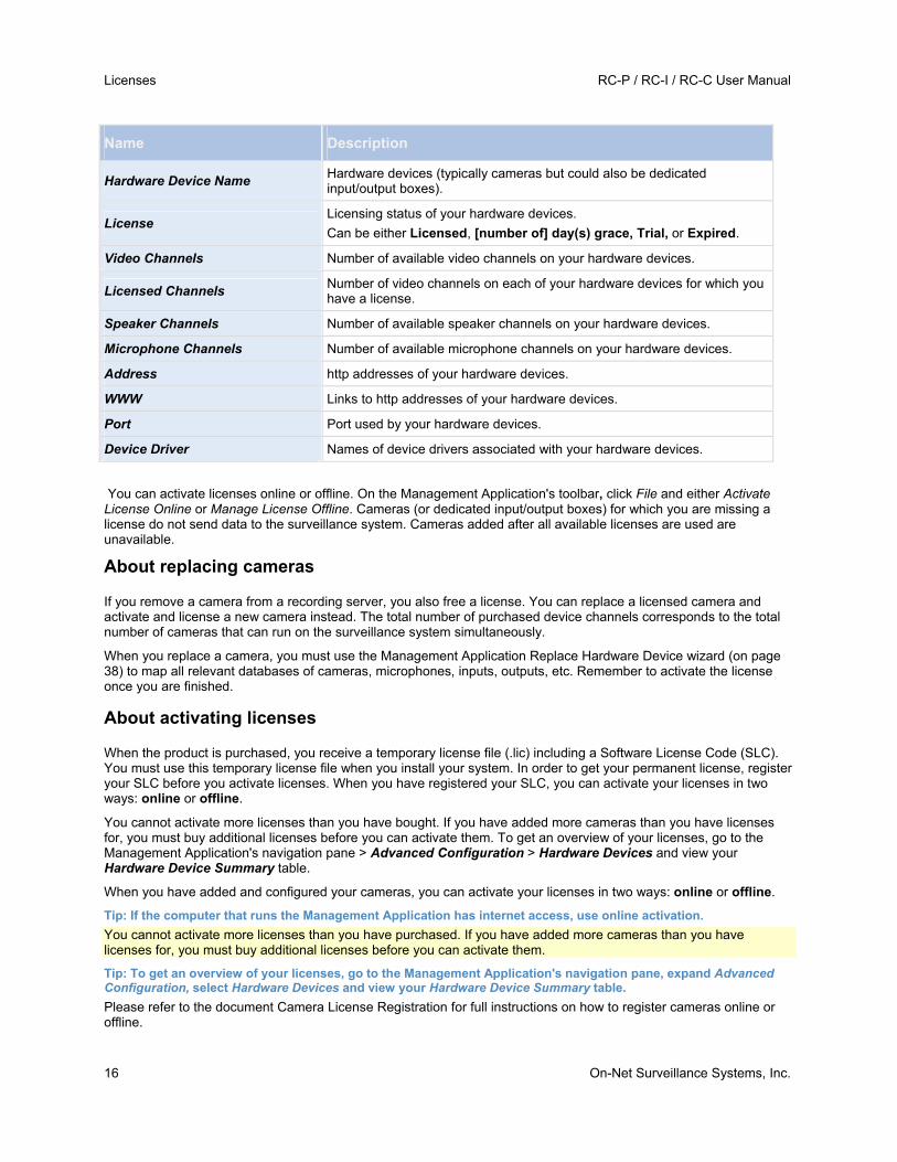
Name Description
Hardware Device Name Hardware devices (typically cameras but could also be dedicated input/output boxes).
License Licensing status of your hardware devices.
Can be either Licensed, [number of] day(s) grace, Trial, or Expired.
Video Channels Number of available video channels on your hardware devices.
Licensed Channels Number of video channels on each of your hardware devices for which you have a license.
Speaker Channels Number of available speaker channels on your hardware devices.
Microphone Channels Number of available microphone channels on your hardware devices.
Address http addresses of your hardware devices.
WWW Links to http addresses of your hardware devices.
Port Port used by your hardware devices.
Device Driver Names of device drivers associated with your hardware devices.
You can activate licenses online or offline. On the Management Application's toolbar, click File and either Activate License Online or Manage License Offline. Cameras (or dedicated input/output boxes) for which you are missing a license do not send data to the surveillance system. Cameras added after all available licenses are used are unavailable.
About replacing cameras
If you remove a camera from a recording server, you also free a license. You can replace a licensed camera and activate and license a new camera instead. The total number of purchased device channels corresponds to the total number of cameras that can run on the surveillance system simultaneously.
When you replace a camera, you must use the Management Application Replace Hardware Device wizard (on page 38) to map all relevant databases of cameras, microphones, inputs, outputs, etc. Remember to activate the license once you are finished.
About activating licenses
When the product is purchased, you receive a temporary license file (.lic) including a Software License Code (SLC). You must use this temporary license file when you install your system. In order to get your permanent license, register your SLC before you activate licenses. When you have registered your SLC, you can activate your licenses in two ways: online or offline.
You cannot activate more licenses than you have bought. If you have added more cameras than you have licenses for, you must buy additional licenses before you can activate them. To get an overview of your licenses, go to the Management Application's navigation pane > Advanced Configuration > Hardware Devices and view your Hardware Device Summary table.
When you have added and configured your cameras, you can activate your licenses in two ways: online or offline.
Tip: If the computer that runs the Management Application has internet access, use online activation.
You cannot activate more licenses than you have purchased. If you have added more cameras than you have licenses for, you must buy additional licenses before you can activate them.
Tip: To get an overview of your licenses, go to the Management Application's navigation pane, expand Advanced Configuration, select Hardware Devices and view your Hardware Device Summary table.
Please refer to the document Camera License Registration for full instructions on how to register cameras online or offline.
RC-P / RC-I / RC-C User Manual Licenses
On-Net Surveillance Systems, Inc. 17
About activating licenses after grace period
If the grace period is exceeded before activation, all cameras that are not activated within the given period become unavailable and cannot send data to the surveillance system.
If you exceed the grace period before you activate a license, the license is not lost. You can activate the license as usual. Configuration, added cameras, and other settings are not removed from the Management Application if a license is activated too late.
Change SLC
If you need to change your SLC and have received a new permanent license file (.lic) from OnSSI via e-mail and saved it to a location accessible from the Management Application, you are ready to import it to your system.
1. On the Management Application's toolbar, click File > Manage License Offline >Import License, and select your saved .lic file to import it.
2. When the new permanent license file is successfully imported, click OK.
Settings RC-P / RC-I / RC-C User Manual
18 On-Net Surveillance Systems, Inc.
Settings
About automatic device discovery
Automatic device discovery allows you to automatically add hardware devices to your system as soon as you connect these to your network. When you enable automatic device discovery, your system configures and set ups cameras automatically without the need for any user interaction in the Management Application. After the camera has been discovered, make sure to refresh the recorder in the Ocularis Administrator application to make the camera available for licensing in Ocularis. Once licensed, the camera may be included in views, on maps, in events, etc.
Note that:
Not all cameras support automatic device discovery.
Cameras respond differently to automatic device discovery. The systems adds some devices (such as Axis models P3301 and P3304) to the system automatically, while some devices from other vendors (such as Sony models SNC-EB520, EM520 and E521) you must turn off and back on again before they are automatically added to your system.
You must still manually activate licenses (see "About activating licenses" on page 16) for your camera. This is to ensure that you only activate cameras set up in an environment with multiple servers on one of the servers.
Change default file paths
To change any of the default file paths:
1. If you want to change the configuration path, stop (see "Start and stop services" on page 116) all services. This step is not necessary if you want to change the default recording or archiving path.
2. On the Management Application menu bar, select Options > Default File Paths...
3. You can now overwrite the necessary paths. Alternatively, click the browse button next to the field and browse to the location. For the default recording path, you can only specify a path to a folder on a local drive. If you are using a network drive, you cannot save recordings if the network drive becomes unavailable.
If you change the default recording or archiving paths and there are existing recordings at the old locations, you must select whether you want to move the recordings to the new locations (recommended), leave them at the old locations, or delete them.
4. Once changes are confirmed, restart (see "Start and stop services" on page 116) all services.
RC-P / RC-I / RC-C User Manual Settings
On-Net Surveillance Systems, Inc. 19
Options
General
In the General settings, you can change a number of settings that affect the general behavior and look of the Management Application.
Automatic device discovery
Automatic device discovery (see "About automatic device discovery" on page 18) is turned off by default in your system. Select the check box to enable this functionality. If the camera should use an additional user name and password besides the camera's default user name and password, select the Use the camera's default user name and password as well as the following credentials check box and type the relevant credentials.
Note: Not all devices support automatic device discovery. If your system does not detect your camera and add it to your system, you must manually add the camera.
System mode
Important: Do not change system mode unless you are absolutely sure that you want the new setting to be in effect immediately after saving.
At some point in time when you save recordings on your system, the storage you save recordings on may become full. Your system offers you two system modes which handle this scenario differently, Classic mode and Evidence collection mode. Evidence collection mode is only available in RC-C.
Classic mode means that the system automatically deletes the oldest saved recordings in order to make room for new recordings. This is how saved recordings have been handled so far in all previous versions of your system. When you remove a hardware device in the Management Application, recordings from the relevant device are deleted from your storage. You can no longer play back recordings from the removed camera in Ocularis Client as these recordings will be deleted from your storage.
Evidence collection mode means that the system stops recording when you reach full storage capacity. All your old recordings are kept in the storage and the system does not save any new recordings. This ensures that video recorded as evidence is never deleted automatically and remains on the hard disk drive until you change system settings in your system or you manually remove the recordings from your storage. Similarly, if you remove a hardware device from the Management Application, recordings from the device are still kept on your storage. You can playback recordings in Ocularis Client even if you have removed the device in the Management Application.
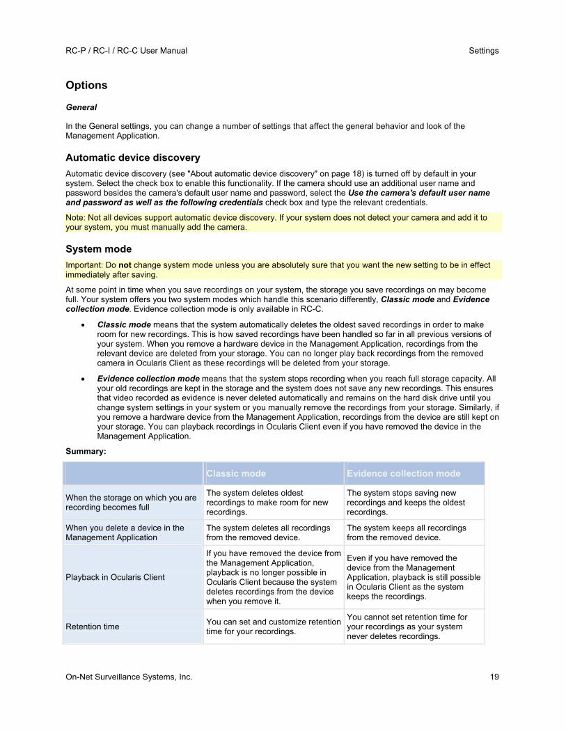
Summary:
Classic mode Evidence collection mode
When the storage on which you are recording becomes full
The system deletes oldest recordings to make room for new recordings.
The system stops saving new recordings and keeps the oldest recordings.
When you delete a device in the Management Application
The system deletes all recordings from the removed device.
The system keeps all recordings from the removed device.
Playback in Ocularis Client
If you have removed the device from the Management Application, playback is no longer possible in Ocularis Client because the system deletes recordings from the device when you remove it.
Even if you have removed the device from the Management Application, playback is still possible in Ocularis Client as the system keeps the recordings.
Retention time You can set and customize retention time for your recordings.
You cannot set retention time for your recordings as your system never deletes recordings.

Settings RC-P / RC-I / RC-C User Manual
20 On-Net Surveillance Systems, Inc.
Choose a system mode that fits your system needs. Most users need the most recent recordings to be available in their storage and should select Classic mode. Evidence mode provides an alternative in cases where all recorded video is considered evidence and therefore must remain on your storage.
Important: Evidence Collection mode is only supported in Ocularis CS 8.5 and later. If you run your system in trial mode, only Classic mode is available. RC-I and RC-P do not support Evidence Collection mode.
Important: If you have upgraded from a previous version of your system, for example Ocularis CS 8.0, Classic mode is the default selection in your system. You must manually change your selection to use Evidence mode.
Language
The Management Application is available in several languages. From the list of languages, select the language you want to use. Restart the Management Application to make the change of language take effect.
User Interface
You can change the way the Management Application behaves. For example, by default, the Management Application asks you to confirm many of your actions. If you feel this is not necessary, you can change the behavior of the Management Application to not ask you again. Go to User Interface to make changes for each action.
Examples of actions you can change:
o When you attempt to delete a hardware device, should the Management Application ask you to confirm that you want to delete the hardware device, or should it delete the hardware device straight away without asking?
o Should your system show live video when you preview camera or would you rather see a snapshot or no preview of the camera?
Click Restore Default Settings below the behavior list to restore your system to its default behavior.
Default File Paths
Your system uses a number of default file paths:
File paths Description
Default recording path for new cameras
All new cameras you add use this path by default for storing recordings. If required, you can change individual cameras' recording paths as part of their individual configuration (see "Recording and archiving paths" on page 65), but you can also change the default recording path so all new cameras you add use a path of your choice.
Default archiving path for new cameras
All new cameras you add use this path by default for archiving (see "About archiving" on page 87). If required, you can change individual cameras' archiving paths as part of their individual configuration, but you can also change the default recording path so all new cameras you add use a path of your choice. Note that camera-specific archiving paths are not relevant if you use dynamic path selection (on page 48) for archiving.
Configuration path The path by default used for storing your system configuration.
RC-P / RC-I / RC-C User Manual Getting started
On-Net Surveillance Systems, Inc. 21
Getting started
About the Getting started page
The Getting started window is always shown when you open the Management Application. The Getting started page provides you with an easy way to go through wizards and serves as a place of reference for users.
Automatic configuration wizard
The Automatic configuration wizard is for easy configuration for first time use of the system. Use the wizard to automatically add cameras to your system using this step-by-step procedure.
Steps in this wizard:
Automatic configuration wizard: First page.......................................................... 21 Automatic configuration wizard: Scanning options .............................................. 21 Automatic configuration wizard: Select hardware manufacturers to scan for ...... 21 Automatic configuration wizard: Scanning for hardware devices......................... 21
Automatic configuration wizard: First page
When you open the Management Application for the first time, the Automatic configuration wizard opens to guide you through the process of adding hardware devices to your system. If you are new to the system, click Yes, configure to scan your network for available cameras and configure your system. To exit and use a more advanced way of adding devices to your system, click Skip to leave the wizard and go to the Management Application to get more options for setting up your system's device configuration.
Automatic configuration wizard: Scanning options
Choose where you want your system to scan for cameras and devices.
By default, the Scan local network checkbox is selected, which means that you only scan your local network for devices. However, if you know the IP address or a range of IP addresses to which cameras and devices are attached, specify these by clicking the Plus icon next to Add the IP addresses or IP ranges to be scanned. You can add more than one range of IP addresses if you need to.
Automatic configuration wizard: Select hardware manufacturers to scan for
If you know the specific manufacturer of your hardware device(s), select these in the drop-down list on this page. You can select as many manufacturers as you want.
Note: By default, all manufacturers are selected. If you want to reduce the scanning time or know the specific manufacturers of your cameras, only select the checkboxes that represents these manufacturers.
Automatic configuration wizard: Scanning for hardware devices
Scanning for hardware devices that match your selected manufacturers begins. A status bar indicates how far in the scan process you are. Once scanning for cameras and devices is complete, you may need to provide user name and password for your selected devices or cameras. When you have typed in the relevant credentials, click the Verify button to add the device to your system.
Getting started RC-P / RC-I / RC-C User Manual
22 On-Net Surveillance Systems, Inc.
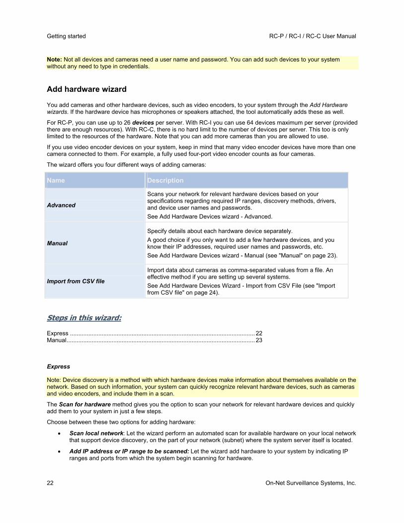
Note: Not all devices and cameras need a user name and password. You can add such devices to your system without any need to type in credentials.
Add hardware wizard
You add cameras and other hardware devices, such as video encoders, to your system through the Add Hardware wizards. If the hardware device has microphones or speakers attached, the tool automatically adds these as well.
For RC-P, you can use up to 26 devices per server. With RC-I you can use 64 devices maximum per server (provided there are enough resources). With RC-C, there is no hard limit to the number of devices per server. This too is only limited to the resources of the hardware. Note that you can add more cameras than you are allowed to use.
If you use video encoder devices on your system, keep in mind that many video encoder devices have more than one camera connected to them. For example, a fully used four-port video encoder counts as four cameras.
The wizard offers you four different ways of adding cameras:
Name Description
Advanced
Scans your network for relevant hardware devices based on your specifications regarding required IP ranges, discovery methods, drivers, and device user names and passwords.
See Add Hardware Devices wizard - Advanced.
Manual
Specify details about each hardware device separately.
A good choice if you only want to add a few hardware devices, and you know their IP addresses, required user names and passwords, etc.
See Add Hardware Devices wizard - Manual (see "Manual" on page 23).
Import from CSV file
Import data about cameras as comma-separated values from a file. An effective method if you are setting up several systems.
See Add Hardware Devices Wizard - Import from CSV File (see "Import from CSV file" on page 24).
Steps in this wizard:
Express ............................................................................................................... 22 Manual................................................................................................................. 23
Express
Note: Device discovery is a method with which hardware devices make information about themselves available on the network. Based on such information, your system can quickly recognize relevant hardware devices, such as cameras and video encoders, and include them in a scan.
The Scan for hardware method gives you the option to scan your network for relevant hardware devices and quickly add them to your system in just a few steps.
Choose between these two options for adding hardware:
Scan local network: Let the wizard perform an automated scan for available hardware on your local network that support device discovery, on the part of your network (subnet) where the system server itself is located.
Add IP address or IP range to be scanned: Let the wizard add hardware to your system by indicating IP ranges and ports from which the system begin scanning for hardware.

RC-P / RC-I / RC-C User Manual Getting started
On-Net Surveillance Systems, Inc. 23
To use the Scan local network method, your system server and your cameras must be on the same layer 2 network, that is a network where all servers, cameras, and so on can communicate without the need for a router. The reason for this is that device discovery relies on direct communication between the system server and the cameras. If you use routers on your network, specify the IP range where you hardware is located using the Add IP address or IP range to be scanned-option or choose one of the Manually specify the hardware to add (see "Manual" on page 23)-methods.
Add hardware: Scanning options
Choose where you want your system to scan for cameras and devices.
By default, the Scan local network checkbox is selected, which means that you only scan your local network for devices. However, if you know the IP address or a range of IP addresses to which cameras and devices are attached, specify these by clicking the Plus icon next to Add the IP addresses or IP ranges to be scanned. You can add more than one range of IP addresses if you need to.
Add hardware: Select hardware manufacturers to scan for
If you know the specific manufacturer of your hardware device(s), select these in the drop-down list on this page. You can select as many manufacturers as you want.
Note: By default, all manufacturers are selected. If you want to reduce the scanning time or know the specific manufacturers of your cameras, only select the checkboxes that represents these manufacturers.
Hardware detection and verification
Scanning for hardware devices that match your selected manufacturers begins. A status bar indicates how far in the scan process you are. Once scanning for cameras and devices is complete, you may need to provide user name and password for your selected devices or cameras. When you have typed in the relevant credentials, click the Verify button to add the device to your system.
Note: Not all devices and cameras need a user name and password. You can add such devices to your system without any need to type in credentials.
Once you have added the number of devices and cameras you want to add, your system sets up storage for you. Storage is the location to which your system saves recordings. By default, your system chooses the location with most available disk space.
Manual
The Manually specify the hardware to add method lets you specify details about each hardware device separately. This options is a good choice if you only want to add a few hardware devices, and you know their IP addresses, user names and passwords and so on. Similarly, automated searches on the local network using the Scan for hardware option might not work for all cameras, for example cameras using the system's Universal Driver. For such cameras, you must add these to the system manually.
Alternatively, choose Import CSV file.... This option lets you import data about hardware devices and cameras as comma-separated values (CSV) (see "Add hardware: Import from CSV file - CSV file format and requirements" on page 25) from a file. This is a highly effective method if you set up several similar systems.
When you use the Manual option, the wizard is divided into these pages:

Getting started RC-P / RC-I / RC-C User Manual
24 On-Net Surveillance Systems, Inc.
Hardware device information, driver selection and verification (see "Information, driver selection and verification" on page 24)
Overview and names
Information, driver selection and verification
Specify information about each hardware device you want to add:
Name Description
IP Address IP address or host name of the hardware device.
Port
Port number on which to scan. The default is port 80. If a hardware device is located behind a NAT-enabled router or a firewall, you may need to specify a different port number. When this is the case, also remember to configure the router/firewall so it maps the port and IP address used by the hardware device.
User Name
User name for the hardware device's administrator account. Many organizations use the hardware device manufacturer's default user names for their hardware devices. If that is the case in your organization, select <default> (do not type a manufacturer's default user name as this can be a source of error—trust that your system knows the manufacturer's default user name).
You can also select other typical user names, such as admin or root, from the list. Type a new user name if you want a user name which is not on the list.
Password Password required to access the administrator account. Some hardware devices do not require user name/password for access.
Driver
The driver to scan for your hardware device. By default, the wizard shows the Autodetect option. The Autodetect option finds the relevant driver automatically. Select a manufacturer if you know the specific manufacturer to reduce scanning time.
Once you have added the number of devices and cameras you want to add, your system sets up storage for you. Storage is the location to which your system saves recordings. By default, your system chooses the location with most available disk space.
Import from CSV file
Import data about hardware devices and cameras as comma-separated values (CSV) from a file. This is a highly effective method if you set up several similar systems.

RC-P / RC-I / RC-C User Manual Getting started
On-Net Surveillance Systems, Inc. 25
ADD HARDWARE DEVICES WIZARD - IMPORT FROM CSV FILE - EXAMPLE OF CSV FILE
The following is an example of a CSV file for use when cameras and server are online. It includes the parameters HardwareAddress, HardwarePort,HardwareUsername, HardwarePassword and HardwareDriverID. Note that HardwareUserName and HardwareDriverID are optional parameters. You can leave out the HardwareUsername if you have not changed the default HardwareUsername for the device. HardwareDriverID is an optional field. If empty, it is automatically set to autodetect.
HardwareAddress;HardwarePort;HardwareUsername;HardwarePassword;HardwareDriverID;
192.168.200.220;80;root;pass;128;
192.168.200.221;80;user;password;165;
192.168.200.222;80;r00t;pass;172;
192.168.200.223;80;;p4ss;
192.168.200.224;80;usEr;pASs;
ADD HARDWARE: IMPORT FROM CSV FILE - CSV FILE FORMAT AND REQUIREMENTS
The CSV file must have a header line (determining what each value on the following lines is about), and the following lines must each contain information about one hardware device only. A minimum of information is always required for each hardware device:
Name Description
HardwareAddress IP address of the hardware device.
HardwareUsername User name for hardware device's administrator account.
HardwarePassword Password for hardware device's administrator account.
HardwareDeviceName Name of the hardware device. Name must unique, and must not contain any of the following special characters: < > & ' " \ / : * ? | [ ]
HardwareDriverID
If cameras and server are offline—specify a HardwareDriverID for each hardware device you want to add. Example: ACTi ACD-2100 105 indicates that you should use 105 as the ID if adding an ACTi ACD-2100 hardware device.
Existing configuration parameters that are not specified in CSV file remain unchanged. If a parameter value for an individual camera in the CSV file is empty, the existing parameter value remains unchanged on that camera. Most system integrators store hardware device information in spreadsheets like Microsoft Excel, from which they can save the information as comma-separated values in a CSV file.
The following applies for the information present in CSV files:
The first line of the CSV file must contain the headers, and following lines must contain information about one hardware device each
Separators can be commas, semicolons or tabs, but cannot be mixed
All lines must contain valid values—pay special attention to the fact that camera names, user names, etc. must be unique, and must not contain any of the following special characters: < > & ' " \ / : * ? | [ ]
There is no fixed order of values, and optional parameters can be omitted entirely
Boolean fields are considered true unless set to 0, false or no
Lines containing only separators are ignored
Empty lines are ignored

Getting started RC-P / RC-I / RC-C User Manual
26 On-Net Surveillance Systems, Inc.
Even though the CSV file format is generally ASCII only, Unicode identifiers are allowed. Even without Unicode identifiers, the entire file or even individual characters are allowed to be Unicode strings.
Configure storage wizard
The Video storage step helps you quickly configure your cameras' video and recording properties.
Steps in this wizard:
Configure storage: Video settings and preview ................................................... 26 Configure storage: Online schedule .................................................................... 26 Live and recording settings Motion-JPEG cameras............................................. 27 Live and recording settings MPEG cameras ....................................................... 28 Drive selection ..................................................................................................... 30 Recording and archiving settings......................................................................... 31
Configure storage: Video settings and preview
Video settings let you control bandwidth, brightness, compression, contrast, resolution, rotation, and more. Use the list on the left side of the wizard window to select a camera and adjust its video settings. Then select the next camera and adjust its settings. Video settings are to a large extent camera-specific, so you must configure these settings individually for each camera.
Click Open Settings Dialog to configure the camera's settings in a separate screen. When you change video settings, they are applied immediately. This means that—for most cameras—you can immediately see the effect of your settings in a preview image. However, it also means that you cannot undo your changes by exiting the wizard. For cameras set to use the video formats MPEG or H.264, you can typically select which live frame rate to use for the camera.
Video settings may feature an Include Date and Time setting. If set to Yes, date and time from the camera are included in the video. Note, however, that cameras are separate units which may have separate timing devices, power supplies, etc. Camera time and system time may therefore not correspond fully, and this may occasionally lead to confusion. As your system time-stamps all frames upon reception, and exact date and time information for each image is already known, OnSSI recommends that you set it to No.
Tip: For consistent time synchronization, you may automatically synchronize camera and system time through a time server if your camera supports this.
Configure storage: Online schedule
Specify when each camera should be online. An online camera is a camera that transfers video to the server for live viewing and further processing. The fact that a camera is online does not in itself mean that your system records video from the camera (configure recording settings on one of the following pages). By default, cameras you add to your system are automatically online (Always on), and you only need to modify their online schedules if you require cameras to be online only at specific times or events. Note, however, that you can change this default as part of the scheduling options (on page 94).
For each camera, you can initially select between two online schedules:
Always on: The camera is always online.
Always off: The camera is never online.
If these two options are too simple for your needs, use the Create / Edit... button to specify online schedules according to your needs, and then select these schedules for your cameras. This way, you can specify whether cameras should be online within specific periods of time, or whether they should start and stop transferring video when specific events occur within specific periods of time.
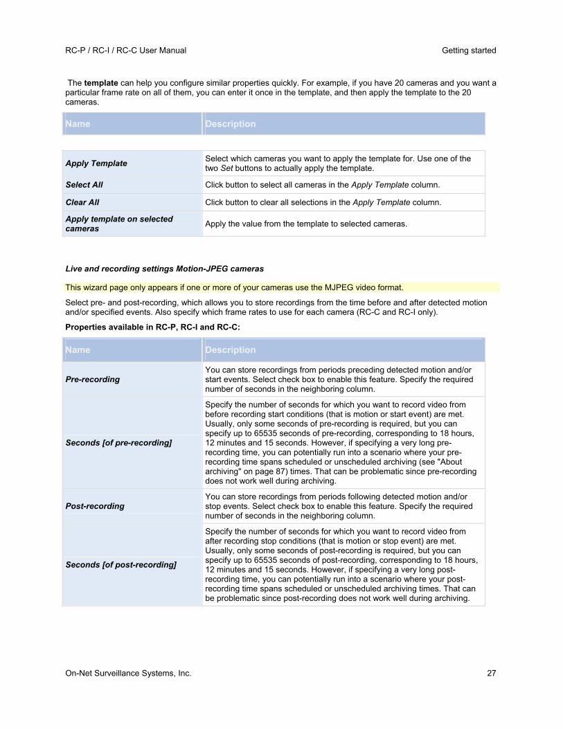
RC-P / RC-I / RC-C User Manual Getting started
On-Net Surveillance Systems, Inc. 27
The template can help you configure similar properties quickly. For example, if you have 20 cameras and you want a particular frame rate on all of them, you can enter it once in the template, and then apply the template to the 20 cameras.
Name Description
Apply Template Select which cameras you want to apply the template for. Use one of the two Set buttons to actually apply the template.
Select All Click button to select all cameras in the Apply Template column.
Clear All Click button to clear all selections in the Apply Template column.
Apply template on selected cameras
Apply the value from the template to selected cameras.
Live and recording settings Motion-JPEG cameras
This wizard page only appears if one or more of your cameras use the MJPEG video format.
Select pre- and post-recording, which allows you to store recordings from the time before and after detected motion and/or specified events. Also specify which frame rates to use for each camera (RC-C and RC-I only).
Properties available in RC-P, RC-I and RC-C:
Name Description
Pre-recording You can store recordings from periods preceding detected motion and/or start events. Select check box to enable this feature. Specify the required number of seconds in the neighboring column.
Seconds [of pre-recording]
Specify the number of seconds for which you want to record video from before recording start conditions (that is motion or start event) are met. Usually, only some seconds of pre-recording is required, but you can specify up to 65535 seconds of pre-recording, corresponding to 18 hours, 12 minutes and 15 seconds. However, if specifying a very long pre-recording time, you can potentially run into a scenario where your pre-recording time spans scheduled or unscheduled archiving (see "About archiving" on page 87) times. That can be problematic since pre-recording does not work well during archiving.
Post-recording You can store recordings from periods following detected motion and/or stop events. Select check box to enable this feature. Specify the required number of seconds in the neighboring column.
Seconds [of post-recording]
Specify the number of seconds for which you want to record video from after recording stop conditions (that is motion or stop event) are met. Usually, only some seconds of post-recording is required, but you can specify up to 65535 seconds of post-recording, corresponding to 18 hours, 12 minutes and 15 seconds. However, if specifying a very long post-recording time, you can potentially run into a scenario where your post-recording time spans scheduled or unscheduled archiving times. That can be problematic since post-recording does not work well during archiving.

Getting started RC-P / RC-I / RC-C User Manual
28 On-Net Surveillance Systems, Inc.
Properties available in RC-C and RC-I only:
Frame Rate Required average frame rate for video from the camera. Select number of frames, then select the time unit interval (second, minute or hour).
Live Frame Rate
Required average frame rate for live video from the camera. Select number of frames, then select the time unit interval (second, minute or hour).
If the camera supports dual stream and dual stream is enabled, the Live Frame Rate column will be read-only with the value Dual streaming—which cannot be altered.
Recording Frame Rate
Required average frame rate for recorded video from the camera. Select number of frames, then select the time unit interval (second, minute or hour).The frame rate must be higher than the frame rate specified under normal mode.
Properties available in RC-P, RC-I and RC-C:
The template can help you configure similar properties quickly. For example, if you have 20 cameras and you want a particular frame rate on all of them, you can enter it once in the template, and then apply the template to the 20 cameras.
Name Description
Apply Template Select which cameras you want to apply the template for. Use one of the two Set buttons to actually apply the template.
Select All Click button to select all cameras in the Apply Template column.
Clear All Click button to clear all selections in the Apply Template column.
Apply template on selected cameras
Apply the value from the template to selected cameras.
Live and recording settings MPEG cameras
This wizard page only appears if one or more of your cameras use the MPEG video format.
Specify which frame rate to use for each camera, and whether to record all frames or keyframes only. You can also select pre- and post-recording, allowing you to store recordings from periods preceding and following detected motion and/or specified events.
Note that all of the properties can also be specified individually for each camera.
Properties available in RC-P, RC-I and RC-C:
Name Description
Live Frame Rate
Required average frame rate for live video from the camera. Select number of frames, then select the time unit interval (second, minute or hour).
If the camera supports dual stream and dual stream is enabled, the Live Frame Rate column will be read-only with the value Dual streaming—which cannot be altered.

RC-P / RC-I / RC-C User Manual Getting started
On-Net Surveillance Systems, Inc. 29
Name Description
Record on
Select under which conditions video from the camera should be recorded:
Always: Record whenever the camera is enabled (see "General" on page 60) and scheduled to be online (see "Online period" on page 95) (the latter allows for time-based recording).
Never: Never record. Live video will be displayed, but—since no video is kept in the database—users will not be able to play back video from the camera.
Motion Detection: Select this to record video in which motion (see "Motion detection & exclude regions" on page 68) is detected. Unless post-recording (see the following) is used, recording will stop immediately after the last motion is detected.
Event: Select this to record video when an event occurs and until another event occurs. Use of recording on event requires that events have been defined in the Management Application, and that you select start and stop events.
Tip: If you have not yet defined any suitable events, you can quickly do it: use the Configure events list, located below the other fields.
Motion Detection and Event: Select this to record video in which motion is detected, or when an event occurs and until another event occurs. Remember to select start and stop events in the neighboring columns.
Pre-recording You can store recordings from periods preceding detected motion and/or start events. Select check box to enable this feature. Specify the required number of seconds in the neighboring column.
Seconds [of pre-recording]
Specify the number of seconds for which you want to record video from before recording start conditions (that is motion or start event) are met. Usually, only some seconds of pre-recording is required, but you can specify up to 65535 seconds of pre-recording, corresponding to 18 hours, 12 minutes and 15 seconds. However, if specifying a very long pre-recording time, you can potentially run into a scenario where your pre-recording time spans scheduled or unscheduled archiving (see "About archiving" on page 87) times. That can be problematic since pre-recording does not work well during archiving.
Post-recording You can store recordings from periods following detected motion and/or stop events. Select check box to enable this feature. Specify the required number of seconds in the neighboring column.
Seconds [of post-recording]
Specify the number of seconds for which you want to record video from after recording stop conditions (that is motion or stop event) are met. Usually, only some seconds of post-recording is required, but you can specify up to 65535 seconds of post-recording, corresponding to 18 hours, 12 minutes and 15 seconds. However, if specifying a very long post-recording time, you can potentially run into a scenario where your post-recording time spans scheduled or unscheduled archiving times. That can be problematic since post-recording does not work well during archiving.
Properties available in RC-C and RC-I only:
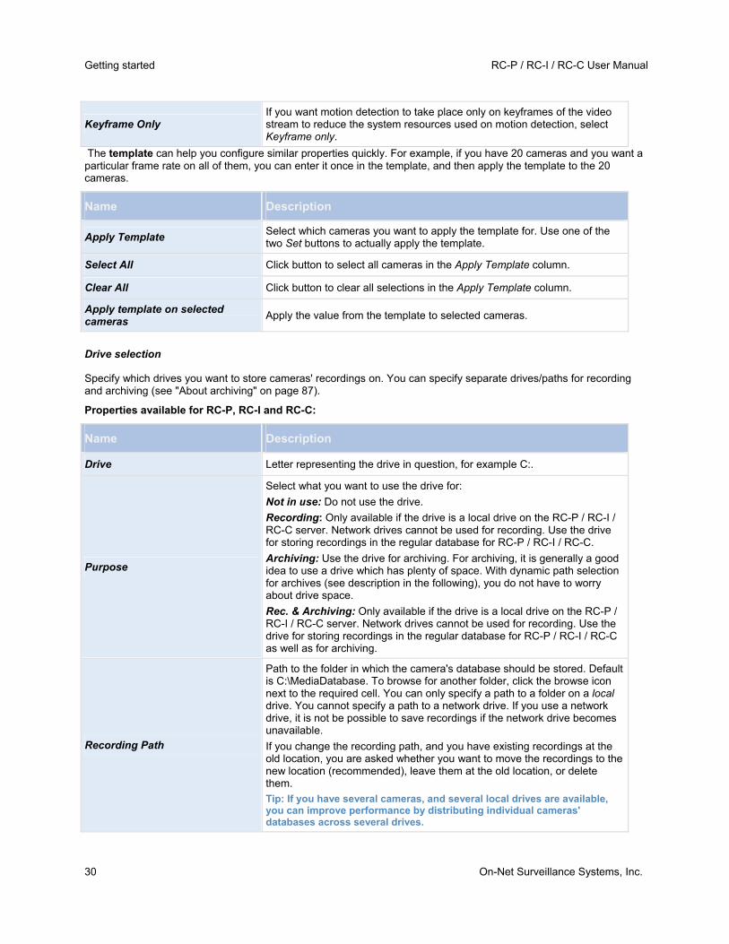
Getting started RC-P / RC-I / RC-C User Manual
30 On-Net Surveillance Systems, Inc.
Keyframe Only If you want motion detection to take place only on keyframes of the video stream to reduce the system resources used on motion detection, select Keyframe only.
The template can help you configure similar properties quickly. For example, if you have 20 cameras and you want a particular frame rate on all of them, you can enter it once in the template, and then apply the template to the 20 cameras.
Name Description
Apply Template Select which cameras you want to apply the template for. Use one of the two Set buttons to actually apply the template.
Select All Click button to select all cameras in the Apply Template column.
Clear All Click button to clear all selections in the Apply Template column.
Apply template on selected cameras
Apply the value from the template to selected cameras.
Drive selection
Specify which drives you want to store cameras' recordings on. You can specify separate drives/paths for recording and archiving (see "About archiving" on page 87).
Properties available for RC-P, RC-I and RC-C:
Name Description
Drive Letter representing the drive in question, for example C:.
Purpose
Select what you want to use the drive for:
Not in use: Do not use the drive.
Recording: Only available if the drive is a local drive on the RC-P / RC-I / RC-C server. Network drives cannot be used for recording. Use the drive for storing recordings in the regular database for RC-P / RC-I / RC-C.
Archiving: Use the drive for archiving. For archiving, it is generally a good idea to use a drive which has plenty of space. With dynamic path selection for archives (see description in the following), you do not have to worry about drive space.
Rec. & Archiving: Only available if the drive is a local drive on the RC-P / RC-I / RC-C server. Network drives cannot be used for recording. Use the drive for storing recordings in the regular database for RC-P / RC-I / RC-C as well as for archiving.
Recording Path
Path to the folder in which the camera's database should be stored. Default is C:\MediaDatabase. To browse for another folder, click the browse icon next to the required cell. You can only specify a path to a folder on a local drive. You cannot specify a path to a network drive. If you use a network drive, it is not be possible to save recordings if the network drive becomes unavailable.
If you change the recording path, and you have existing recordings at the old location, you are asked whether you want to move the recordings to the new location (recommended), leave them at the old location, or delete them.
Tip: If you have several cameras, and several local drives are available, you can improve performance by distributing individual cameras' databases across several drives.

RC-P / RC-I / RC-C User Manual Getting started
On-Net Surveillance Systems, Inc. 31
Name Description
Archiving Path
Only editable if not using dynamic paths for archiving (see "About archiving" on page 87). Path to the folder in which the camera's archived recordings should be stored. Default is C:\MediaDatabase.
To browse for another folder, click the browse icon next to the relevant cell. If you change the archiving path, and there are existing archived recordings at the old location, you are asked whether you want to move the archived recordings to the new location (recommended), leave them at the old location, or delete them. Note that if you move archived recordings, RC-P / RC-I / RC-C will also archive what is currently in the camera database. In case you wonder why the camera database is empty just after you have moved archived recordings, this is the reason.
Total Size Total size of the drive.
Free Space Amount of unused space left on the drive.
Dynamic path selection for archives
If using this option (highly recommended), you should select a number of different local drives for archiving. If the path containing the RC-P / RC-I / RC-C database is on one of the drives you have selected for archiving, RC-P / RC-I / RC-C will always try to archive to that drive first. If not, RC-P / RC-I / RC-C automatically archives to the archiving drive with the most available space at any time, provided there is not a camera database using that drive. Which drive has the most available space may change during the archiving process, and archiving may therefore happen to several archiving drives during the same process. This fact will have no impact on how users find and view archived recordings.
Archiving Times
Specify when you want RC-P / RC-I / RC-C to automatically move recordings to your archiving path(s). You can specify up to 24 archiving times per day, with minimum one hour between each one. Select the hour, minute and second values and click the up and down buttons to increase or decrease values, or simply overwrite the selected value, and then click Add. The more you expect to record, the more often you should archive.
Properties available in RC-C and RC-I only:
Network Drive
Lets you add a network drive to the list of drives. First specify the network drive, then click Add (the button becomes available when you specify a network drive) . Note that network drives cannot be used for recording, only for archiving.
Recording and archiving settings
Select recording and archiving (see "About archiving" on page 87) paths for each individual camera.
All properties on a white background are editable, properties on a light bluebackground cannot be edited.

Getting started RC-P / RC-I / RC-C User Manual
32 On-Net Surveillance Systems, Inc.
Name Description
Recording Path
Path to the folder in which the camera's database should be stored. Default is C:\MediaDatabase. To browse for another folder, click the browse icon next to the required cell. You can only specify a path to a folder on a local drive. You cannot specify a path to a network drive. If you use a network drive, it is not be possible to save recordings if the network drive becomes unavailable.
If you change the recording path, and you have existing recordings at the old location, you are asked whether you want to move the recordings to the new location (recommended), leave them at the old location, or delete them.
Tip: If you have several cameras, and several local drives are available, you can improve performance by distributing individual cameras' databases across several drives.
Archiving Path
Only editable if not using dynamic paths for archiving (see "About archiving" on page 87). Path to the folder in which the camera's archived recordings should be stored. Default is C:\MediaDatabase.
To browse for another folder, click the browse icon next to the relevant cell. If you change the archiving path, and there are existing archived recordings at the old location, you are asked whether you want to move the archived recordings to the new location (recommended), leave them at the old location, or delete them. Note that if you move archived recordings, RC-P / RC-I / RC-C will also archive what is currently in the camera database. In case you wonder why the camera database is empty just after you have moved archived recordings, this is the reason.
Retention time
Total amount of time for which you want to keep recordings from the camera (that is, recordings in the camera's database as well as any archived recordings). Default is 7 days.
Retention time covers the total amount of time you want to keep recordings for. In earlier RC-P / RC-I / RC-C versions, time limits were specified separately for the database and archives.
The template can help you configure similar properties quickly. For example, if you have 20 cameras and you want a particular frame rate on all of them, you can enter it once in the template, and then apply the template to the 20 cameras.
Name Description
Apply Template Select which cameras you want to apply the template for. Use one of the two Set buttons to actually apply the template.
Select All Click button to select all cameras in the Apply Template column.
Clear All Click button to clear all selections in the Apply Template column.
Apply template on selected cameras
Apply the value from the template to selected cameras.
Adjust motion detection wizard
The Adjust Motion Detection wizard helps you quickly configure your cameras' motion detection properties.

RC-P / RC-I / RC-C User Manual Getting started
On-Net Surveillance Systems, Inc. 33
Cameras that do not support multiple simultaneous video streams cannot connect to the surveillance server and the Management Application at the same time. Therefore, we recommend that you stop (see "Start and stop services" on page 116) the Recording Server service when you configure such devices for motion detection and PTZ.
Steps in this wizard:
Exclude regions ................................................................................................... 33 Motion Detection.................................................................................................. 33
Exclude regions
Exclude regions lets you disable motion detection in specific areas of cameras' views. Disabling motion detection in certain areas may help you avoid detection of irrelevant motion, for example if a camera covers an area where a tree is swaying in the wind or where cars regularly pass by in the background.
Cameras that do not support multiple simultaneous video streams cannot connect to the surveillance server and the Management Application at the same time. OnSSI recommends that you stop (see "Start and stop services" on page 116) the Recording Server service when you configure such devices for motion detection and PTZ.
For each camera for which exclude regions are relevant, use the list in the left side of the wizard window to select the camera and define its exclude regions. Exclude regions are camera-specific, and must therefore be configured individually for each camera on which they are required.
When you have selected a camera, you see a preview from the camera. You define regions to exclude in the preview, which is divided into small sections by a grid.
To make the grid visible, select the Show Grid check box.
To define exclude regions, drag the mouse pointer over the required areas in the preview while pressing the mouse button down. Left mouse button selects a grid section; right mouse button clears a grid section. Selected areas are highlighted in blue.
Tip: With the Include All button, you can quickly select all grid sections in the preview. This can be advantageous if you want to disable motion detection in most areas of the preview, in which case you can clear the few sections in which you do not want to disable motion detection. With the Exclude All button you can quickly deselect them all.
Motion Detection
Motion detection is a key element in most surveillance systems. Depending on your configuration, motion detection settings may determine when video is recorded (saved on the surveillance system server), when notifications are sent, when output (a light or siren) is triggered, etc.
It is important that you find the best possible motion detection settings for each camera to avoid unnecessary recordings, notifications, etc. Depending on the physical location of your cameras, it is a good idea to test settings under different physical conditions (day/night, windy/calm weather, etc.).
Cameras that do not support multiple simultaneous video streams cannot connect to the surveillance server and the Management Application at the same time. OnSSI recommends that you stop (see "Start and stop services" on page 116) the Recording Server service when you configure such devices for motion detection and PTZ.
You can configure motion detection settings for each camera, or for several cameras at once. Use the list in the left pane of the wizard window to select cameras. To select several cameras at a time, press CTRL or SHIFT while you select. When you select a camera, you see a preview from that camera. If you select several cameras, you see a preview from the last camera you select. A green area in the preview indicates motion.
Properties available in RC-P, RC-I and RC-C:

Getting started RC-P / RC-I / RC-C User Manual
34 On-Net Surveillance Systems, Inc.
Name Description
Sensitivity
Adjust the Sensitivity slider so that irrelevant background noise is filtered out, and only real motion is shown in green. Alternatively, specify a value between 0 and 256 in the field next to the slider to control the sensitivity setting.
The slider determines how much each pixel must change before it is regarded as motion. With a high sensitivity, very little change in a pixel is required before it is regarded as motion. The more you drag the slider to the left, the more of the preview becomes green. This is because with high sensitivity, even the slightest pixel change is regarded as motion.
Motion
Adjust the Motion slider so that motion detection is only triggered by the required level of motion. The selected motion level is indicated by the black vertical line in the Level bar above the sliders. The black vertical line serves as a threshold. When motion is above (to the right of) the selected level, the bar changes color from green to red, indicating a positive motion detection.
Alternatively, specify a value between 0 and 10000 in the field on the left to control the motion setting.
The more you drag the slider to the left, the more positive motion detections you see because less change will be needed to trigger a positive motion detection. The number of positive motion detections may also affect the amount of video you record, the amount of notifications you receive, etc.
Detection interval
Specify how often motion detection analysis is carried out on video from the camera. The default is every 240 milliseconds (close to once a quarter of a second). The interval is applied regardless of your cameras' frame rate settings.
Adjusting this setting can help lower the amount of system resources used on motion detection.
Detection resolution
Specify whether the full image or a selected percentage of the image should be analyzed. For example, by specifying 25%, every fourth pixel is analyzed instead of all pixels, reducing the system resources used but also offering less accurate motion detection.
Property available in RC-C and RC-I only:
Keyframe Only If you want motion detection to take place only on keyframes of the video stream to reduce the system resources used on motion detection, select Keyframe only.
Manage user access wizard
Use the Manage user access step to add individual users so they can access the system and its clients. The access summary at the end of the wizard lists the cameras your users have access to.
Important: When you use the wizard, all users you add get access to all cameras, including any new cameras added at a later stage. You can, however, specify access settings, users and user rights (see "Configure user and group rights" on page 112) separately, see Configure server access (on page 106). You cannot add users to groups (see "Add user groups" on page 111).

RC-P / RC-I / RC-C User Manual Getting started
On-Net Surveillance Systems, Inc. 35
Steps in this wizard:
Basic and Windows users ................................................................................... 35 Access summary ................................................................................................. 35
Basic and Windows users
Active Directory® is available in RC-C and RC-I only.
You can add client users in two ways. You can combine these if you need to.
Name Description
Basic user Create a dedicated surveillance system user account with basic user name and password authentication for each individual user.
Windows user Import users defined locally on the server, or users from Active Directory, and authenticate them based on their Windows login.
Note: You must define users as local PC users on the server and disable simple file sharing on the server.
Add Basic users
1. Specify a user name and password, and click the Add Basic User button. Repeat as required.
Add Windows users
1. Click Add Windows User... to open the Select Users or Groups dialog. You can only make selections from the local computer, even if you click the Locations... button.
2. In Enter the object names to select, enter the user name(s), then use the Check Names feature to verify the user name. If you enter several user names, separate each name with a semicolon. Example: Brian; Hannah; Karen; Wayne.
3. When done, click OK.
Important: When a user who has been added from a local database logs in with a client, the user should not specify any server name, PC name, or IP address as part of the user name. Example of a correctly specified user name: USER001, not: PC001/USER001. The user should, of course, still specify a password and any relevant server information.
Important: Ocularis Base needs only 1 user account with administrative privileges. If you use OpenSight, you should create an additional user account with only those privileges you want to provide to the remote monitor.
Access summary
The access summary lists which cameras your users have access to. When you use the wizard, all users you have added have access all to cameras, including any new cameras added at a later stage. You can, however, limit individual users' access to cameras by changing their individual rights (see "Configure user and group rights" on page 112).

Advanced configuration RC-P / RC-I / RC-C User Manual
36 On-Net Surveillance Systems, Inc.
Advanced configuration
Hardware devices
About hardware devices
You add cameras and other hardware devices, such as video encoders, to your RC-P / RC-I / RC-C system through the Add Hardware Devices... wizard (see "Add hardware wizard" on page 22). If microphones or speakers are attached to a hardware device, they are automatically added as well (if your software supports this).
About microphones
In your system, Microphones are typically attached to hardware devices, and therefore physically located next to cameras. Operators, with the necessary rights, can then listen to recordings through the Ocularis Client (provided the computer running the Ocularis Client has speakers attached). You manage microphones in RC-P / RC-I / RC-C, meaning you can always manage the microphones attached to cameras, not microphones attached to Ocularis Client operators' computers.
If you have added more microphones to your system than you need, you can hide the ones you do not need by right-clicking the relevant microphone or speaker and select Hide. If you need the hidden microphone again, you can right-click the overall microphone icon and select Show Hidden Items.
About speakers
Speakers are attached to devices, and typically physically located next to cameras. They can typically transmit information to people near a camera. Operators with the necessary rights can talk through speakers using Ocularis Client (provided the computer running Ocularis Client has a microphone attached).
Example: An elevator is stuck. Through a camera mounted in the elevator, Ocularis Client operators can see that there is an elderly lady in the elevator. A microphone attached to the camera records that the lady says: “I am afraid. Please help me out!” Through a speaker attached to the camera, operators can tell the lady that: “Help is on its way. You should be out in less than fifteen minutes.”
If you have added more speakers to your system than you need, you can hide the ones you do not need by right-clicking the relevant speaker and select Hide. If you need the hidden speaker again, you can right-click the overall speaker icon and select Show Hidden Items.
About recording audio
Available functionality depends on your product version.
If you record audio, it is important that you note the following:
Your system only records incoming audio (from microphones). The system does not record outgoing audio (from speakers).
Audio recording affects video storage capacity. The system records audio to the associated camera’s database. Therefore, it is important to remember that the database is likely to become full earlier if you record audio and video than if you only record video. The fact that the database becomes full is not in itself a problem since RC-P / RC-I / RC-C automatically archives (see "About archiving" on page 87) data if the database becomes full. However, you may need additional archiving space if you record audio.
o Example: If you use MPEG4, each one-second video GOP (Group Of Pictures) are stored in one record in the database. Each second of audio is stored in one record in the database. This reduces the database’s video storage capacity to half its capacity, because half of the database’s records is used for

RC-P / RC-I / RC-C User Manual Advanced configuration
On-Net Surveillance Systems, Inc. 37
storing audio. Consequently, the database runs full sooner, and automatic archiving takes place more often than if you were only recording video.
o Example: If you use MJPEG, audio is stored in one record for every JPEG for as long as the audio block size does not exceed the time between the JPEGs. In extreme cases, this reduces the database’s video storage capacity to half its capacity, because half of the database’s records is used for storing audio. If you use very high frame rates, which means less time between each JPEG, a smaller portion of the database is used for storing audio records, and consequently a larger portion is available for storing video. The result is that the database runs full sooner, and automatic archiving takes place more often than if you were only recording video.
The above examples are simplified. The exact available video storage capacity also depends on GOP/JPEG and audio kilobyte size.
About dedicated input/output devices
You can add a number of dedicated input/output (I/O) hardware devices to your system. For information about which I/O hardware devices your system supports, see the release notes.
When you add I/O hardware devices, input on them can be used for generating events in your system and events in your system can be used for activating output on the I/O hardware devices. This means that you can use I/O hardware devices in your events-based system setup in the same way as a camera.
With certain I/O hardware devices, the surveillance system must regularly check the state of the hardware devices' input ports to detect whether input has been received. Such state checking at regular intervals is called polling. The interval between state checks, called a polling frequency, is specified as part of the general ports and polling properties (see "Ports and polling" on page 80). For such I/O hardware devices, the polling frequency should be set to the lowest possible value (one tenth of a second between state checks). For information about which I/O hardware devices require polling, see the release notes.
About replacing hardware devices
If you need to, you can replace a hardware device that you have added and configured on your system with a new one, for example to replace a physical camera on your network.
Open the Replace Hardware Device wizard (on page 38), which helps you through the entire replacement process on the surveillance system server, including:
Detecting the new hardware device
Specifying license for the new hardware device
Deciding what to do with existing recordings from the old hardware device
Configure hardware devices
Once you have added hardware devices (see "Add hardware wizard" on page 22), you can specify/edit device-specific properties, such as the IP address, which video channels to use, which COM ports to use for controlling attached PTZ (pan-tilt-zoom) cameras, etc.
1. In the Management Application's navigation pane, expand Advanced Configuration, expand Hardware Devices, right-click the relevant hardware device, and select Properties.
2. Specify Name and video channels, Network, device type and license (see "Network, device type, and license" on page 40), and PTZ device (on page 41), properties as required.
3. Save your configuration changes by clicking Save in the yellow notification bar in the upper-right corner of the Management Application.

Advanced configuration RC-P / RC-I / RC-C User Manual
38 On-Net Surveillance Systems, Inc.
Delete hardware devices
IMPORTANT: If you delete a hardware device you will not only delete all cameras, speakers and microphones attached to the hardware device. You will also delete any recordings from cameras on the hardware device.
1. In the Management Application's navigation pane, expand Advanced Configuration, expand Hardware Devices, right-click the hardware device you want to delete, and select Delete Hardware device.
2. Confirm that you want to delete the hardware device and all its recordings.
3. Save your configuration changes by clicking Save in the yellow notification bar in the upper-right corner of the Management Application.
4. Restart (see "Start and stop services" on page 116) the Recording Server service.
Alternately, you can also consider disabling the individual cameras, speakers or microphones connected to the hardware device:
1. In the Management Application's navigation pane, expand Advanced Configuration, expand Hardware Devices, and expand the relevant hardware device.
2. Right-click the camera, microphone or speaker that you want to disable, and select Disable.
3. Save your configuration changes by clicking Save in the yellow notification bar in the upper-right corner of the Management Application.
4. Restart (see "Start and stop services" on page 116) the Recording Server service.
Replace Hardware Device wizard
The Replace Hardware Device wizard helps you replace a hardware device that you have previously added to and configured on your surveillance system. To open the Replace Hardware Device wizard, right-click the device that you want to replace and select Replace Hardware Device.
The wizard is divided into these pages:
New hardware device information (on page 38)
Database action (see "Camera and database action" on page 39)
New hardware device information
Specify details about the new hardware device:
Name Description
IP Address IP address or host name of the hardware device.
Port
Port number on which to scan. The default is port 80. If a hardware device is located behind a NAT-enabled router or a firewall, you may need to specify a different port number. When this is the case, also remember to configure the router/firewall so it maps the port and IP address used by the hardware device.

RC-P / RC-I / RC-C User Manual Advanced configuration
On-Net Surveillance Systems, Inc. 39
Name Description
User Name
User name for the hardware device's administrator account. Many organizations use the hardware device manufacturer's default user names for their hardware devices. If that is the case in your organization, select <default> (do not type a manufacturer's default user name as this can be a source of error—trust that your system knows the manufacturer's default user name).
You can also select other typical user names, such as admin or root, from the list. Type a new user name if you want a user name which is not on the list.
Password Password required to access the administrator account. Some hardware devices do not require user name/password for access.
To specify which device driver to use for the new hardware device, you can:
Select the video device driver in the Hardware device type list, and then click Auto-detect/Verify Hardware Device Type to verify that the driver matches the hardware device.
- or -
Click Auto-detect/Verify Hardware Device Type to automatically detect and verify the right driver.
When the right driver is found, the Serial number (MAC address) field displays the MAC address of the new hardware device. When done, click Next.
Camera and database action
The last page of the Replace Hardware wizard lets you decide what to do with the camera and the database containing recordings from the camera attached to the old hardware device. For multi-camera devices, such as video encoders, you must decide what to do for each video channel on the new hardware device.
The table in the left side of the wizard page lists available video channels on the new hardware device. For a regular single-camera hardware device, there are only one video channel. For video encoders, there are typically several video channels.
1. For each video channel, use the table's Inherit column to select which camera from the old hardware device should be inherited by the new hardware device.
2. Then decide what to do with camera databases. You have three options:
o Inherit existing database(s): The cameras you selected to be inherited by the new hardware device inherit camera names, recordings databases as well as any archives from the old hardware device. Databases and archives (see "About archiving" on page 87) are renamed to reflect the new hardware device's MAC address and video channels. The rights (see "Configure user and group rights" on page 112) of users with access to the inherited cameras are automatically updated so they can view both old and new recordings. Users do not notice the hardware device replacement since camera names remain the same.
o Delete the existing database(s): The databases of the cameras you selected to be inherited by the new hardware device are not deleted. New databases are created for future recordings, but it is not possible to view recordings from before the hardware replacement.
o Leave the existing database(s): The databases of the cameras you selected to be inherited by the new hardware device are not deleted. New databases are created for future recordings, but even though the old databases still exist on the RC-P / RC-I / RC-C server, it is not possible to view recordings from before the hardware replacement. Should you later want to delete the old databases, you must delete this manually.
3. If the new hardware device has fewer video channels than the old hardware device, it is not possible for the new hardware device to inherit all cameras from the old hardware device. When that is the case, you are

Advanced configuration RC-P / RC-I / RC-C User Manual
40 On-Net Surveillance Systems, Inc.
asked what to do with the databases of cameras that could not be inherited by the new hardware device. You have two options:
o Delete the databases for the cameras that are not inherited: The databases of the cameras that could not be inherited by the new hardware devices are deleted. It is not possible to view recordings from before the hardware replacement. New databases are, of course, created for future recordings by the new hardware devices.
o Leave the databases for the cameras that are not inherited: The databases of the cameras that could not be inherited by the new hardware devices are not deleted. Even though the old databases still exist on the RC-P / RC-I / RC-C server, it is not possible to view recordings from before the hardware replacement. Should you later want to delete the old databases, you must delete this manually. New databases will, of course, be created for future recordings by the new hardware devices.
4. Click Finish.
When you are ready, restart (see "Start and stop services" on page 116) the Recording Server service. The hardware replacement are not evident in clients until you restart the Recording Server service.
Hardware properties
Hardware name and video channels
When you configure hardware devices (on page 37), specify the following properties:
Name Description
Hardware name
The name as it appears in the Management Application, the Ocularis Administrator, and Ocularis Clients (standard, Mobile and Web). You may, however, assign an additional camera name in Ocularis that will not affect the name stored here. You can overwrite the existing name with a new one. Names must be unique, and must not contain any of these special characters: < > & ' " \ / : * ? | [ ]
Video channel # enabled
Enable/disable each of the selected hardware device's video channels. Many hardware devices only have a single video channel, in which case only one channel will be listed. Other hardware devices—typically video encoder devices—have several video channels.
If some of the channels are unavailable, this is because you are not licensed to use all of a video encoder device's channels. Example: You have a video encoder device with four channels, but your license for the device only allows you to use two of them. In that case, you can only have two channels enabled at a time, while the two other channels are disabled. Note that you are free to select which two channels you want to enable. Contact your OnSSI vendor if you need to change your number of licenses.
Network, device type, and license
When you configure hardware devices (on page 37), specify the following properties:
Name Description
IP Address IP address or host name of the hardware device.
HTTP Port Port to use for HTTP communication with the hardware device. Default is port 80. To use the default port, select Use default HTTP port.
FTP port Port to use for FTP communication with the hardware device. Default port is port 21. To use the default port, select Use default FTP port.

RC-P / RC-I / RC-C User Manual Advanced configuration
On-Net Surveillance Systems, Inc. 41
Name Description
User name Only relevant when you have selected Server requires login. Specify the user name required for using the SMTP server.
User Name
User name for the hardware device's administrator account. Many organizations use the hardware device manufacturer's default user names for their hardware devices. If that is the case in your organization, select <default> (do not type a manufacturer's default user name as this can be a source of error—trust that your system knows the manufacturer's default user name).
You can also select other typical user names, such as admin or root, from the list. Type a new user name if you want a user name which is not on the list.
Password Password for the hardware device's administrator account, a.k.a. the root password.
Hardware type Read-only field displaying the type of video device driver used for communication with the hardware device.
Serial number (MAC address) Read-only field displaying the serial number of device. The serial number is usually identical to the 12-character hexadecimal MAC address of the hardware device (example: 0123456789AF).
License information The current license status for the hardware.
Replace Hardware Device
Opens a wizard (see "Replace Hardware Device wizard" on page 38), with which you can replace the selected hardware device with another one if you need to. This can be relevant if you replace a physical camera on your network. The wizard helps you take all relevant issues into account: for example, deciding what to do with recordings from cameras attached to the old hardware device, etc.
PTZ device
The PTZ Device tab is only available if you configure (see "Configure hardware devices" on page 37) video encoder hardware devices on which the use of PTZ (pan-tilt-zoom) cameras is possible:
Name Description
Connected cameras have Pan-tilt-zoom capabilities
Select the checkbox if any of the cameras attached to the video encoder device is a PTZ camera.
PTZ type on COM#
If a PTZ camera is controlled through a COM port, select the relevant option. Options are device-specific, depending on which PTZ protocols the device uses. Select None if you have no PTZ cameras controlled through COM ports.
The table in the lower half of the dialog contains a row for each video channel on the hardware device. First row from the top corresponds to video channel 1, second row from the top corresponds to video channel 2, etc.
Name Description
Name Name of the camera attached to the video channel in question.

Advanced configuration RC-P / RC-I / RC-C User Manual
42 On-Net Surveillance Systems, Inc.
Name Description
Type
Select whether the camera on the selected camera channel is fixed or moveable:
Fixed: Camera is a regular camera mounted in a fixed position
Moveable: Camera is a PTZ camera
Port Available only if Moveable is selected in the Type column. Select which COM port on the video encoder to use for controlling the PTZ camera.
Port Address
Available only if Moveable is selected in the Type column. Lets you specify port address of the camera. The port address will normally be 1. If using daisy chained PTZ cameras, the port address will identify each of them, and you should verify your settings with those recommended in the documentation for the camera.
Speaker properties
When you configure video and recording (see "About video and recording configuration" on page 42) for specific cameras, you can determine when to record audio. Your choice applies for all cameras on your RC-P / RC-I / RC-C system.
Name Description
Enabled
Speakers are by default enabled, meaning that they are able to transfer audio to RC-P / RC-I / RC-C. If required, you can disable an individual speaker, in which case no audio will be transferred from the speaker to RC-P / RC-I / RC-C.
Speaker name
The name as it appears in the Management Application, the Ocularis Administrator, and Ocularis Clients (standard, Mobile and Web). You may, however, assign an additional camera name in Ocularis that will not affect the name stored here. You can overwrite the existing name with a new one. Names must be unique, and must not contain any of these special characters: < > & ' " \ / : * ? | [ ]
Cameras and storage information
About video and recording configuration
Once you have added hardware devices and attached cameras, you can configure video and recording settings in three ways:
Name Description
Wizard-driven Guided configuration where you can specify video, recording and archiving settings for all your cameras.
General Specify video, recording and shared settings (such as dynamic archiving paths and whether to record audio or not) for all your cameras.
Camera-specific Specify video, recording and camera-specific settings for each individual camera.

RC-P / RC-I / RC-C User Manual Advanced configuration
On-Net Surveillance Systems, Inc. 43
About database resizing
In case recordings for a camera get bigger than expected, or the available drive space is suddenly reduced in another way, an advanced database resizing procedure automatically takes place:
If archives (see "About archiving" on page 87) are present on the same drive as the camera's database, the oldest archive for all cameras archived on that drive is moved to another drive (moving archives is only possible if you use dynamic archiving (see "Dynamic path selection" on page 48), with which you can archive to several different drives) or—if moving is not possible—deleted.
If no archives are present on the drive containing the camera's database, the size of all camera databases on the drive is reduced by deleting a percentage of their oldest recordings, temporarily limiting the size of all databases.
When the Recording Server service (see "About services" on page 115) is restarted upon such database resizing, the original database sizes are used. Therefore, you should make sure to solve the drive size problem.
About motion detection settings
Motion detection settings are linked to the Recording properties (see "Recording" on page 64) settings for the camera. Motion detection is enabled by default. Disabling it will improve CPU and RAM performance of your RC-P / RC-I / RC-C system. In the following two tables, you can see the differences between enabling (table 1) and disabling (table 2) built-in motion detection for a camera.
Enabled motion detection
Recording properties setting
Recordings Motion-based events
Non-motion based events
Sequences
Always Yes Yes Yes Yes
Never No Yes Yes No
Built-in Motion Detection Yes Yes Yes Yes
Built-in Motion Detection & Event or Event only
Yes Yes Yes Yes
Disabled motion detection
Camera's recording settings
Recordings Motion-based events
Non-motion based events
Sequences
Always Yes No Yes No
Never No No Yes No
Built-in Motion Detection No No Yes No
Built-in Motion Detection & Event or Event only
Yes (depending on settings)
No Yes (depending on settings)
No
About motion detection and PTZ cameras
Motion detection generally works the same way for PTZ (pan-tilt-zoom) cameras as it does for regular cameras. However, you cannot configure motion detection separately for each of a PTZ camera's preset positions.

Advanced configuration RC-P / RC-I / RC-C User Manual
44 On-Net Surveillance Systems, Inc.
In order to activate unwanted recordings, notifications and more, the system automatically disables motion detection while a PTZ camera moves between two preset positions. After a number of seconds, the transition time, specified as part of the PTZ camera's PTZ patrolling properties (see "PTZ patrolling" on page 71), the system automatically enables motion detection again.
Configure camera-specific schedules
If you base your schedule profile—or parts of it—on events within periods of time, remember to select Start event and Stop event from the lists below the calendar section.
Tip: If you have not yet defined any suitable events, you can quickly do it: use the Configure events list, located below the other fields.
The fact that a camera transfers video to RC-P / RC-I / RC-C does not necessarily mean that video from the camera is recorded. Recording is configured separately, see Configure video and recording (see "About video and recording configuration" on page 42).
For each camera, you can create schedule profiles based on:
Properties available in RC-P, RC-I and RC-C:
Online periods
Periods of time (example: Mondays from 08.30 until 17.45) displays in pink.
Events within periods of time (example: from Event A occurs until Event B occurs Mondays from 08.30 until 17.45) displays in yellow.
The two options can be combined , but they cannot overlap in time.
Speedup
Periods of time (example: Mondays from 08.30 until 17.45), displays in olive green.
E-mail notification
Periods of time (example: Mondays from 08.30 until 17.45), displays in blue.
PTZ patrolling
Periods of time (example: Mondays from 08.30 until 17.45), displays in red.
If use of one patrolling profile is followed immediately by use of another, run your mouse pointer over the red bar to see which patrolling profile applies and when.
Properties available in RC-C and RC-I only:
SMS notification
Periods of time (example: Mondays from 08.30 until 17.45), displays in green. (for supported products)
Set up a profile
1. In the Schedule Profiles list, select Add new....
2. In the Add Profile dialog, enter a name for the profile. Names must not contain any of these special characters: < > & ' " \ / : * ? | [ ]
3. In the top right corner of the dialog, select Set camera to start/stop on time (to base subsequent settings on periods of time) or Set camera to start/stop on event (to base subsequent settings on events within periods of time).
Tip: You can combine the two, so you may return to this step in order to toggle between the two options.

RC-P / RC-I / RC-C User Manual Advanced configuration
On-Net Surveillance Systems, Inc. 45
4. In the calendar section, place your mouse pointer at a required start point, then hold down the left mouse button, drag the mouse pointer and release at the required end point.
o You specify each day separately.
o You specify time in increments of five minutes. RC-P / RC-I / RC-C helps you by showing the time over which your mouse pointer is positioned.
If you base your schedule profile—or parts of it—on events within periods of time, remember to select Start event and Stop event from the lists below the calendar section.
o Tip: If you have not yet defined any suitable events, you can quickly do it: use the Configure events list, located below the other fields.
o To delete an unwanted part of a schedule profile, right-click it and select Delete.
o To quickly fill or clear an entire day, double-click the name of the day.
o As an alternative to dragging inside the calendar section, use the Start time, End time and Day fields, then the Change Period or Set Period button as required. When using the Start time and End time fields, remember that time is specified in increments of five minutes. You cannot specify a period shorter than five minutes, and you can only use times like 12:00, 12.05, 12:10, 12:15, etc. If you specify a time outside of the five-minute intervals, such as 12:13, you will get an error message.
Configure when cameras should do what
Available functionality depends on your product version.
Use the scheduling feature to configure when:
Cameras should be online (that is transfer video to RC-P / RC-I / RC-C)
Cameras should use speedup (that is use a higher than normal frame rate)
You want to receive email and (for supported products) SMS notifications regarding cameras
PTZ cameras should patrol, and according to which patrolling profile (not in RC-P)
Archiving should take place:
See Configure general scheduling and archiving (on page 92) and Configure camera-specific schedules (on page 44).
Configure motion detection
To configure motion detection, do the following:
1. In the Management Application navigation pane, expand Advanced Configuration, expand Cameras and Storage Information, right-click the relevant camera, and select Properties.
2. In the Camera Properties window, select the Recording Properties tab, and select the relevant settings (see "About motion detection settings" on page 43).
3. Select the Motion Detection tab. If there are any areas to exclude from motion detection (for example, if the camera covers an area where a tree is swaying in the wind), you can exclude that area (see "Exclude regions" on page 33) by selecting it with your mouse.
4. Fill in the relevant properties (see "Motion detection & exclude regions" on page 68). Note that there are some differences in motion-detection behavior for PTZ cameras (see "About motion detection and PTZ cameras" on page 43).

Advanced configuration RC-P / RC-I / RC-C User Manual
46 On-Net Surveillance Systems, Inc.
Disable or delete cameras
All cameras are enabled by default. This means that video from the cameras can be transferred to your system if the cameras are scheduled to be online (see "Online period" on page 95).
To disable a camera:
1. In the Management Application's navigation pane, expand Advanced Configuration, expand Cameras and Storage Information, double-click the camera you want to disable, and clear the Enabled box.
2. Save your configuration changes by clicking Save in the yellow notification bar in the upper-right corner of the Management Application.
To delete a camera, you have to delete the hardware device (see "Delete hardware devices" on page 38). If you delete the hardware device, you also delete any attached microphones or speakers. If you do not want this, consider disabling the camera instead.
Move PTZ type 1 and 3 to required positions
For PTZ types 1 and 3, you can move the PTZ camera to required positions in several different ways.
1. Click the required position in the camera preview (if supported by the camera).
2. Use the sliders located near the camera preview to move the PTZ camera along each of its axes: the X-axis (for panning left/right), the Y-axis (for tilting up/down), and the Z-axis (for zooming in and out; to zoom in, move the slider towards Tele; to zoom out, move the slider towards Wide).
3. Use the navigation buttons to move the camera in the direction indicated by the arrow. Control zoom level by use of the magnifier icon.
Recording and storage properties
Recording and archiving paths
When you configure video and recording (see "About video and recording configuration" on page 42), you can specify certain properties for many cameras in one step. Do this to speed up things, or because the properties in question are shared by all cameras rather than being specific to individual cameras.
All properties on a white background are editable, properties on a light blue background cannot be edited. Note that all of the properties can also be specified individually for each camera.

RC-P / RC-I / RC-C User Manual Advanced configuration
On-Net Surveillance Systems, Inc. 47
Name Description
Template
The template can help you configure similar properties quickly. Say you have 20 cameras and you want to change the recording path, archiving path, and retention time for all of them. Instead of having to enter the same three pieces of information 20 times, you can simply enter them once in the template, and then apply the template to the 20 cameras with only two clicks.
Apply Template Select which cameras you want to apply the template for. Use one of the two Set buttons to actually apply the template.
Camera Name
The name as it appears in the Management Application, the Ocularis Administrator, and Ocularis Clients (standard, Mobile and Web). You may, however, assign an additional camera name in Ocularis that will not affect the name stored here. You can overwrite the existing name with a new one. Names must be unique, and must not contain any of these special characters: < > & ' " \ / : * ? | [ ]
Shortcut This field is not in use.
Recording Path
Path to the folder in which the camera's database should be stored. Default is C:\MediaDatabase. To browse for another folder, click the browse icon next to the required cell. You can only specify a path to a folder on a local drive. You cannot specify a path to a network drive. If you use a network drive, it is not be possible to save recordings if the network drive becomes unavailable.
If you change the recording path, and you have existing recordings at the old location, you are asked whether you want to move the recordings to the new location (recommended), leave them at the old location, or delete them.
Tip: If you have several cameras, and several local drives are available, you can improve performance by distributing individual cameras' databases across several drives.
Archiving Path
Only editable if not using dynamic paths for archiving (see "About archiving" on page 87). Path to the folder in which the camera's archived recordings should be stored. Default is C:\MediaDatabase.
To browse for another folder, click the browse icon next to the relevant cell. If you change the archiving path, and there are existing archived recordings at the old location, you are asked whether you want to move the archived recordings to the new location (recommended), leave them at the old location, or delete them. Note that if you move archived recordings, RC-P / RC-I / RC-C will also archive what is currently in the camera database. In case you wonder why the camera database is empty just after you have moved archived recordings, this is the reason.
Retention time
Total amount of time for which you want to keep recordings from the camera (that is, recordings in the camera's database as well as any archived recordings). Default is 7 days.
Retention time covers the total amount of time you want to keep recordings for. In earlier versions, time limits were specified separately for the database and archives.
Camera Click the Open button to configure detailed and/or camera-specific settings for the selected camera.
Select All Click button to select all cameras in the Apply Template column.
Clear All Click button to clear all selections in the Apply Template column.
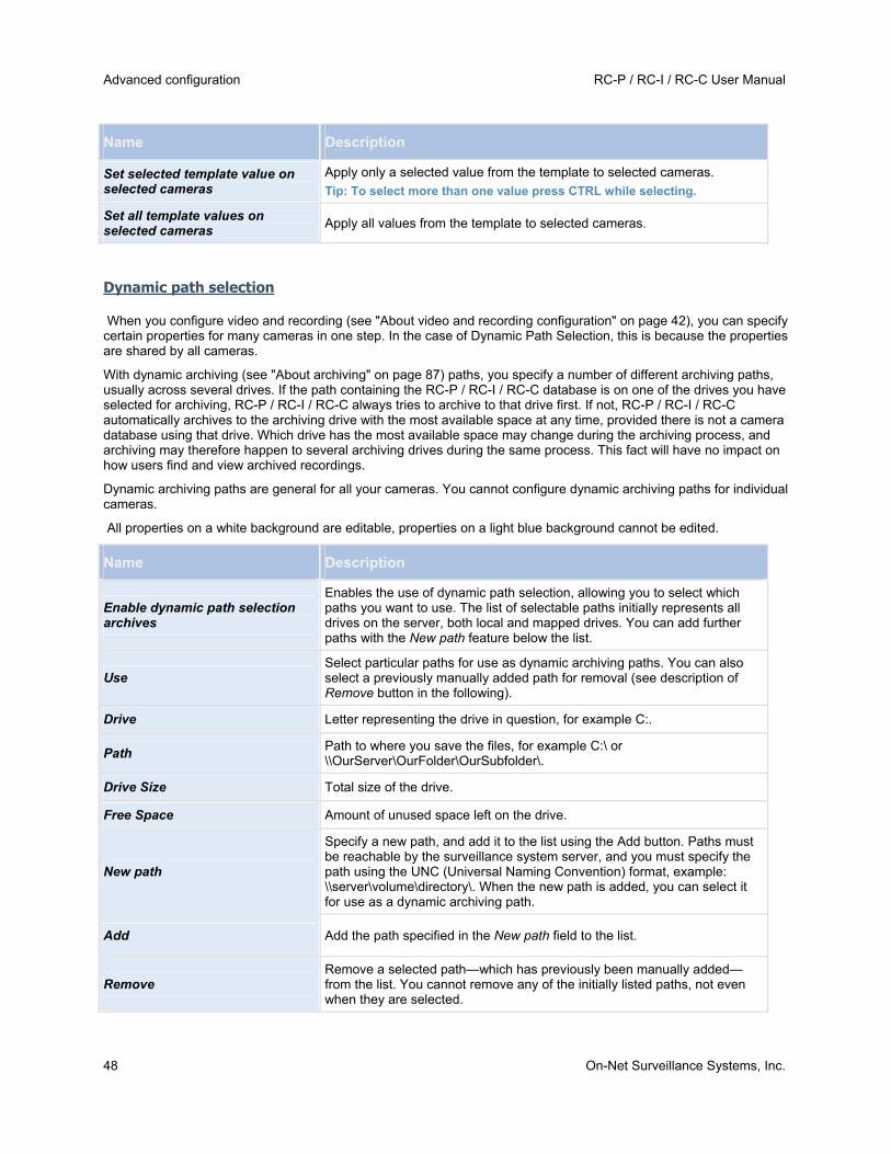
Advanced configuration RC-P / RC-I / RC-C User Manual
48 On-Net Surveillance Systems, Inc.
Name Description
Set selected template value on selected cameras
Apply only a selected value from the template to selected cameras.
Tip: To select more than one value press CTRL while selecting.
Set all template values on selected cameras
Apply all values from the template to selected cameras.
Dynamic path selection
When you configure video and recording (see "About video and recording configuration" on page 42), you can specify certain properties for many cameras in one step. In the case of Dynamic Path Selection, this is because the properties are shared by all cameras.
With dynamic archiving (see "About archiving" on page 87) paths, you specify a number of different archiving paths, usually across several drives. If the path containing the RC-P / RC-I / RC-C database is on one of the drives you have selected for archiving, RC-P / RC-I / RC-C always tries to archive to that drive first. If not, RC-P / RC-I / RC-C automatically archives to the archiving drive with the most available space at any time, provided there is not a camera database using that drive. Which drive has the most available space may change during the archiving process, and archiving may therefore happen to several archiving drives during the same process. This fact will have no impact on how users find and view archived recordings.
Dynamic archiving paths are general for all your cameras. You cannot configure dynamic archiving paths for individual cameras.
All properties on a white background are editable, properties on a light blue background cannot be edited.
Name Description
Enable dynamic path selection archives
Enables the use of dynamic path selection, allowing you to select which paths you want to use. The list of selectable paths initially represents all drives on the server, both local and mapped drives. You can add further paths with the New path feature below the list.
Use Select particular paths for use as dynamic archiving paths. You can also select a previously manually added path for removal (see description of Remove button in the following).
Drive Letter representing the drive in question, for example C:.
Path Path to where you save the files, for example C:\ or \\OurServer\OurFolder\OurSubfolder\.
Drive Size Total size of the drive.
Free Space Amount of unused space left on the drive.
New path
Specify a new path, and add it to the list using the Add button. Paths must be reachable by the surveillance system server, and you must specify the path using the UNC (Universal Naming Convention) format, example: \\server\volume\directory\. When the new path is added, you can select it for use as a dynamic archiving path.
Add Add the path specified in the New path field to the list.
Remove Remove a selected path—which has previously been manually added—from the list. You cannot remove any of the initially listed paths, not even when they are selected.

RC-P / RC-I / RC-C User Manual Advanced configuration
On-Net Surveillance Systems, Inc. 49
Video recording
When you configure video and recording (see "About video and recording configuration" on page 42), you can specify certain properties for many cameras in one step. Do this to speed up things, or because the properties in question are shared by all cameras rather than being specific to individual cameras.
In RC-P / RC-I / RC-C, the term recording means saving video and, if applicable, audio from a camera in the camera's database on the surveillance system server. Video/audio is often saved only when there is a reason to do so, for example as long as motion is detected, when an event occurs and until another event occurs, or within a certain period of time.
All properties on a white background are editable, properties on a light blue background cannot be edited. Note that all of the Video Recording properties can also be specified individually for each camera (see "Recording" on page 64).
Name Description
Template
The template can help you configure similar properties quickly. Say you have 20 cameras and you want to change the recording path, archiving path, and retention time for all of them. Instead of having to enter the same three pieces of information 20 times, you can simply enter them once in the template, and then apply the template to the 20 cameras with only two clicks.
Apply Template Select which cameras you want to apply the template for. Use one of the two Set buttons to actually apply the template.
Camera Name
The name as it appears in the Management Application, the Ocularis Administrator, and Ocularis Clients (standard, Mobile and Web). You may, however, assign an additional camera name in Ocularis that will not affect the name stored here. You can overwrite the existing name with a new one. Names must be unique, and must not contain any of these special characters: < > & ' " \ / : * ? | [ ]
Record on
Select under which conditions video from the camera should be recorded:
Always: Record whenever the camera is enabled (see "General" on page 60) and scheduled to be online (see "Online period" on page 95) (the latter allows for time-based recording).
Never: Never record. Live video will be displayed, but—since no video is kept in the database—users will not be able to play back video from the camera.
Motion Detection: Select this to record video in which motion (see "Motion detection & exclude regions" on page 68) is detected. Unless post-recording (see the following) is used, recording will stop immediately after the last motion is detected.
Event: Select this to record video when an event occurs and until another event occurs. Use of recording on event requires that events have been defined in the Management Application, and that you select start and stop events.
Tip: If you have not yet defined any suitable events, you can quickly do it: use the Configure events list, located below the other fields.
Motion Detection and Event: Select this to record video in which motion is detected, or when an event occurs and until another event occurs. Remember to select start and stop events in the neighboring columns.

Advanced configuration RC-P / RC-I / RC-C User Manual
50 On-Net Surveillance Systems, Inc.
Name Description
Start Event Select required start event. Recording will begin when the start event occurs (or earlier if using pre-recording; see the following).
Stop Event Select required stop event. Recording will end when the stop event occurs (or later if using post-recording; see the following).
Pre-recording You can store recordings from periods preceding detected motion and/or start events. Select check box to enable this feature. Specify the required number of seconds in the neighboring column.
Seconds [of pre-recording]
Specify the number of seconds for which you want to record video from before recording start conditions (that is motion or start event) are met. Usually, only some seconds of pre-recording is required, but you can specify up to 65535 seconds of pre-recording, corresponding to 18 hours, 12 minutes and 15 seconds. However, if specifying a very long pre-recording time, you can potentially run into a scenario where your pre-recording time spans scheduled or unscheduled archiving (see "About archiving" on page 87) times. That can be problematic since pre-recording does not work well during archiving.
Post-recording You can store recordings from periods following detected motion and/or stop events. Select check box to enable this feature. Specify the required number of seconds in the neighboring column.
Seconds [of post-recording]
Specify the number of seconds for which you want to record video from after recording stop conditions (that is motion or stop event) are met. Usually, only some seconds of post-recording is required, but you can specify up to 65535 seconds of post-recording, corresponding to 18 hours, 12 minutes and 15 seconds. However, if specifying a very long post-recording time, you can potentially run into a scenario where your post-recording time spans scheduled or unscheduled archiving times. That can be problematic since post-recording does not work well during archiving.
Camera Click the Open button to configure detailed and/or camera-specific settings for the selected camera.
Select All Click button to select all cameras in the Apply Template column.
Clear All Click button to clear all selections in the Apply Template column.
Set selected template value on selected cameras
Apply only a selected value from the template to selected cameras.
Tip: To select more than one value press CTRL while selecting.
Set all template values on selected cameras
Apply all values from the template to selected cameras.
IF THE CAMERA USES THE MJPEG VIDEO FORMAT
With MJPEG, you can define frame rates for regular as well as speedup modes. If the camera offers dual stream, you can also enable this.
Note that there are three places where you can set frame rate:
Live Frame Rate - used for the regular recording stream
Live Frame Rate - used when speeding up recordings in connection with motion detection or similar functionality.
FPS (Frames per second) - used for the additional stream used for live viewing.

RC-P / RC-I / RC-C User Manual Advanced configuration
On-Net Surveillance Systems, Inc. 51
Regular frame rate mode:
Properties available for RC-P, RC-I and RC-C:
Name Description
Frame Rate Required average frame rate for video from the camera. Select number of frames, then select the time unit interval (second, minute or hour).
Properties available in RC-C and RC-I only:
Live Frame Rate
Required average frame rate for live video from the camera. Select number of frames, then select the time unit interval (second, minute or hour).
If the camera supports dual stream and dual stream is enabled, the Live Frame Rate column will be read-only with the value Dual streaming—which cannot be altered.
Recording Frame Rate
Required average frame rate for recorded video from the camera. Select number of frames, then select the time unit interval (second, minute or hour).The frame rate must be higher than the frame rate specified under normal mode.
Speedup frame rate mode:
Properties available in RC-P, RC-I and RC-C:
Name Description
Enable speedup frame rate The speedup feature lets you use a higher than normal frame rate if motion is detected and/or an event occurs. When you enable speedup, further columns for specifying speedup details become available.
Frame Rate
Speedup frame rate for viewing video from the camera. Select number of frames, then select the time unit interval (second, minute or hour).The frame rate must be higher than the frame rate specified under normal mode.
On motion Select this check box to use the speedup frame rates when motion is detected. The camera will return to the normal frame rates two seconds after the last motion is detected.
On event
Select this check box to use the speedup frame rates when an event occurs and until another event occurs. Use of speedup on event requires that events have been defined, and that you select start and stop events in the neighboring lists.
Tip: If you have not yet defined any suitable events, you can quickly do it: use the Configure events list, located below the other fields.
Start Event Select required start event. The camera will begin using the speedup frame rates when the start event occurs.
Stop Event Select required stop event. The camera will return to the normal frame rates when the stop event occurs.
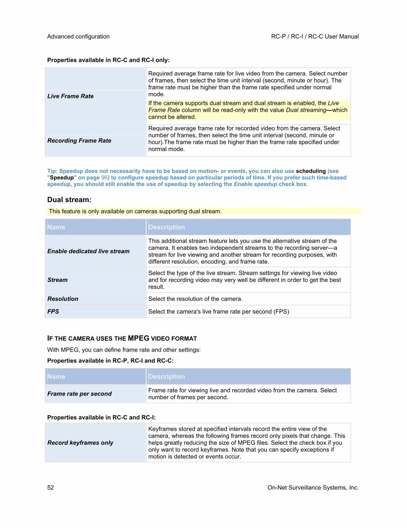
Advanced configuration RC-P / RC-I / RC-C User Manual
52 On-Net Surveillance Systems, Inc.
Properties available in RC-C and RC-I only:
Live Frame Rate
Required average frame rate for live video from the camera. Select number of frames, then select the time unit interval (second, minute or hour). The frame rate must be higher than the frame rate specified under normal mode.
If the camera supports dual stream and dual stream is enabled, the Live Frame Rate column will be read-only with the value Dual streaming—which cannot be altered.
Recording Frame Rate
Required average frame rate for recorded video from the camera. Select number of frames, then select the time unit interval (second, minute or hour).The frame rate must be higher than the frame rate specified under normal mode.
Tip: Speedup does not necessarily have to be based on motion- or events, you can also use scheduling (see "Speedup" on page 96) to configure speedup based on particular periods of time. If you prefer such time-based speedup, you should still enable the use of speedup by selecting the Enable speedup check box.
Dual stream:
This feature is only available on cameras supporting dual stream.
Name Description
Enable dedicated live stream
This additional stream feature lets you use the alternative stream of the camera. It enables two independent streams to the recording server—a stream for live viewing and another stream for recording purposes, with different resolution, encoding, and frame rate.
Stream Select the type of the live stream. Stream settings for viewing live video and for recording video may very well be different in order to get the best result.
Resolution Select the resolution of the camera.
FPS Select the camera's live frame rate per second (FPS)
IF THE CAMERA USES THE MPEG VIDEO FORMAT
With MPEG, you can define frame rate and other settings:
Properties available in RC-P, RC-I and RC-C:
Name Description
Frame rate per second Frame rate for viewing live and recorded video from the camera. Select number of frames per second.
Properties available in RC-C and RC-I:
Record keyframes only
Keyframes stored at specified intervals record the entire view of the camera, whereas the following frames record only pixels that change. This helps greatly reducing the size of MPEG files. Select the check box if you only want to record keyframes. Note that you can specify exceptions if motion is detected or events occur.
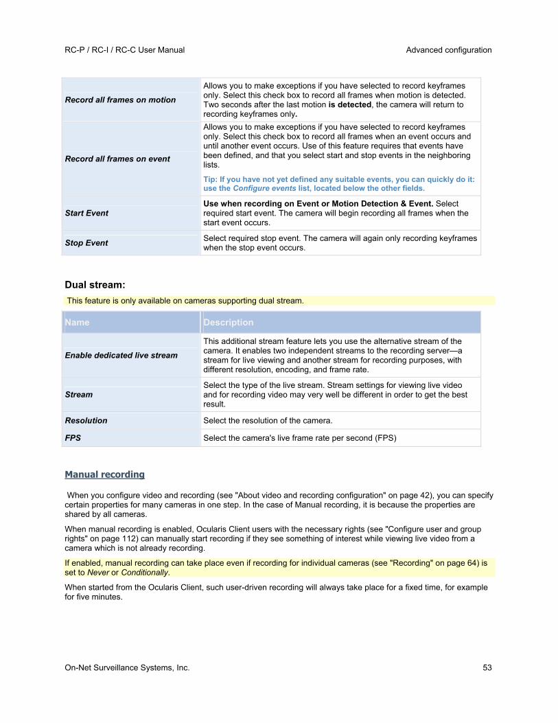
RC-P / RC-I / RC-C User Manual Advanced configuration
On-Net Surveillance Systems, Inc. 53
Record all frames on motion
Allows you to make exceptions if you have selected to record keyframes only. Select this check box to record all frames when motion is detected. Two seconds after the last motion is detected, the camera will return to recording keyframes only.
Record all frames on event
Allows you to make exceptions if you have selected to record keyframes only. Select this check box to record all frames when an event occurs and until another event occurs. Use of this feature requires that events have been defined, and that you select start and stop events in the neighboring lists.
Tip: If you have not yet defined any suitable events, you can quickly do it: use the Configure events list, located below the other fields.
Start Event Use when recording on Event or Motion Detection & Event. Select required start event. The camera will begin recording all frames when the start event occurs.
Stop Event Select required stop event. The camera will again only recording keyframes when the stop event occurs.
Dual stream:
This feature is only available on cameras supporting dual stream.
Name Description
Enable dedicated live stream
This additional stream feature lets you use the alternative stream of the camera. It enables two independent streams to the recording server—a stream for live viewing and another stream for recording purposes, with different resolution, encoding, and frame rate.
Stream Select the type of the live stream. Stream settings for viewing live video and for recording video may very well be different in order to get the best result.
Resolution Select the resolution of the camera.
FPS Select the camera's live frame rate per second (FPS)
Manual recording
When you configure video and recording (see "About video and recording configuration" on page 42), you can specify certain properties for many cameras in one step. In the case of Manual recording, it is because the properties are shared by all cameras.
When manual recording is enabled, Ocularis Client users with the necessary rights (see "Configure user and group rights" on page 112) can manually start recording if they see something of interest while viewing live video from a camera which is not already recording.
If enabled, manual recording can take place even if recording for individual cameras (see "Recording" on page 64) is set to Never or Conditionally.
When started from the Ocularis Client, such user-driven recording will always take place for a fixed time, for example for five minutes.

Advanced configuration RC-P / RC-I / RC-C User Manual
54 On-Net Surveillance Systems, Inc.
Name Description
Enable manual recording Select check box to enable manual recording and specify further details.
Default duration of manual recording
Period of time (in seconds) during which user-driven recording take place. Default duration is 300 seconds, corresponding to five minutes.
Maximum duration of manual recording
Maximum allowed period of time for user-driven recording. This maximum is not relevant in connection with manual recording started from the Ocularis Client, since such manual recording will always take place for a fixed time. In some installations it is, however, also possible to combine manual recording with third-party applications if integrating these with RC-P / RC-I / RC-C through an API or similar, and in such cases specifying a maximum duration may be relevant. If you are simply using manual recording in connection with the Ocularis Client, disregard this property.
Frame rate - MJPEG
When you configure video and recording (see "About video and recording configuration" on page 42), you can specify certain properties for many cameras in one step. Do this to speed up things, or because the properties in question are shared by all cameras rather than being specific to individual cameras.
All properties on a white background are editable, properties on a light blue background cannot be edited. Note that all of the Frame rate - MJPEG properties can also be specified individually for each camera (see "Recording" on page 64) using MJPEG.
TEMPLATE AND COMMON PROPERTIES
Name Description
Template
The template can help you configure similar properties quickly. Say you have 20 cameras and you want to change the recording path, archiving path, and retention time for all of them. Instead of having to enter the same three pieces of information 20 times, you can simply enter them once in the template, and then apply the template to the 20 cameras with only two clicks.
Apply Template Select which cameras you want to apply the template for. Use one of the two Set buttons to actually apply the template.
Select All Click button to select all cameras in the Apply Template column.
Clear All Click button to clear all selections in the Apply Template column.
Set selected template value on selected cameras
Apply only a selected value from the template to selected cameras.
Tip: To select more than one value press CTRL while selecting.
Set all template values on selected cameras
Apply all values from the template to selected cameras.
Camera Name
The name as it appears in the Management Application, the Ocularis Administrator, and Ocularis Clients (standard, Mobile and Web). You may, however, assign an additional camera name in Ocularis that will not affect the name stored here. You can overwrite the existing name with a new one. Names must be unique, and must not contain any of these special characters: < > & ' " \ / : * ? | [ ]
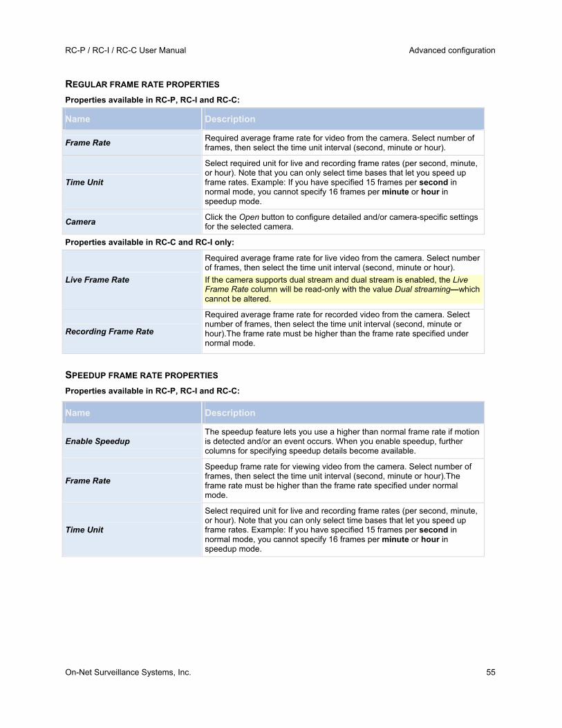
RC-P / RC-I / RC-C User Manual Advanced configuration
On-Net Surveillance Systems, Inc. 55
REGULAR FRAME RATE PROPERTIES
Properties available in RC-P, RC-I and RC-C:
Name Description
Frame Rate Required average frame rate for video from the camera. Select number of frames, then select the time unit interval (second, minute or hour).
Time Unit
Select required unit for live and recording frame rates (per second, minute, or hour). Note that you can only select time bases that let you speed up frame rates. Example: If you have specified 15 frames per second in normal mode, you cannot specify 16 frames per minute or hour in speedup mode.
Camera Click the Open button to configure detailed and/or camera-specific settings for the selected camera.
Properties available in RC-C and RC-I only:
Live Frame Rate
Required average frame rate for live video from the camera. Select number of frames, then select the time unit interval (second, minute or hour).
If the camera supports dual stream and dual stream is enabled, the Live Frame Rate column will be read-only with the value Dual streaming—which cannot be altered.
Recording Frame Rate
Required average frame rate for recorded video from the camera. Select number of frames, then select the time unit interval (second, minute or hour).The frame rate must be higher than the frame rate specified under normal mode.
SPEEDUP FRAME RATE PROPERTIES
Properties available in RC-P, RC-I and RC-C:
Name Description
Enable Speedup The speedup feature lets you use a higher than normal frame rate if motion is detected and/or an event occurs. When you enable speedup, further columns for specifying speedup details become available.
Frame Rate
Speedup frame rate for viewing video from the camera. Select number of frames, then select the time unit interval (second, minute or hour).The frame rate must be higher than the frame rate specified under normal mode.
Time Unit
Select required unit for live and recording frame rates (per second, minute, or hour). Note that you can only select time bases that let you speed up frame rates. Example: If you have specified 15 frames per second in normal mode, you cannot specify 16 frames per minute or hour in speedup mode.

Advanced configuration RC-P / RC-I / RC-C User Manual
56 On-Net Surveillance Systems, Inc.
Name Description
Speedup On
Motion Detection: Select this to speed up when motion (see "Motion detection & exclude regions" on page 68) is detected. Normal frame rates will be resumed immediately after the last motion is detected.
Event: Select this to speed up when an event occurs and until another event occurs. Use of speedup on event requires that events have been defined, and that you select start and stop events in the neighboring columns.
Tip: If you have not yet defined any suitable events, you can quickly do it: use the Configure events list, located below the other fields.
Motion Detection & Event: Select this to speed up when motion is detected, or when an event occurs and until another event occurs. Remember to select start and stop events in the neighboring columns.
Schedule Only Select this to speed up according to the camera's speedup schedule (see "Speedup" on page 96) only.
Start Event Select required start event. The camera will begin using the speedup frame rates when the start event occurs.
Stop Event Select required stop event. The camera will return to the normal frame rates when the stop event occurs.
Camera Click the Open button to configure detailed and/or camera-specific settings for the selected camera.
Live Frame Rate
Required average frame rate for live video from the camera. Select number of frames, then select the time unit interval (second, minute or hour). The frame rate must be higher than the frame rate specified under normal mode.
If the camera supports dual stream and dual stream is enabled, the Live Frame Rate column will be read-only with the value Dual streaming—which cannot be altered.
Recording Frame Rate
Required average frame rate for recorded video from the camera. Select number of frames, then select the time unit interval (second, minute or hour).The frame rate must be higher than the frame rate specified under normal mode.
Frame Rate - MPEG
When you configure video and recording (see "About video and recording configuration" on page 42), you can specify certain properties for many cameras in one step. Do this to speed up things, or because the properties in question are shared by all cameras rather than being specific to individual cameras.
Note that you can also specify all of the Frame Rate - MPEG properties individually for each camera (see "Recording" on page 64) using MPEG.
Properties available in RC-P, RC-I and RC-C:
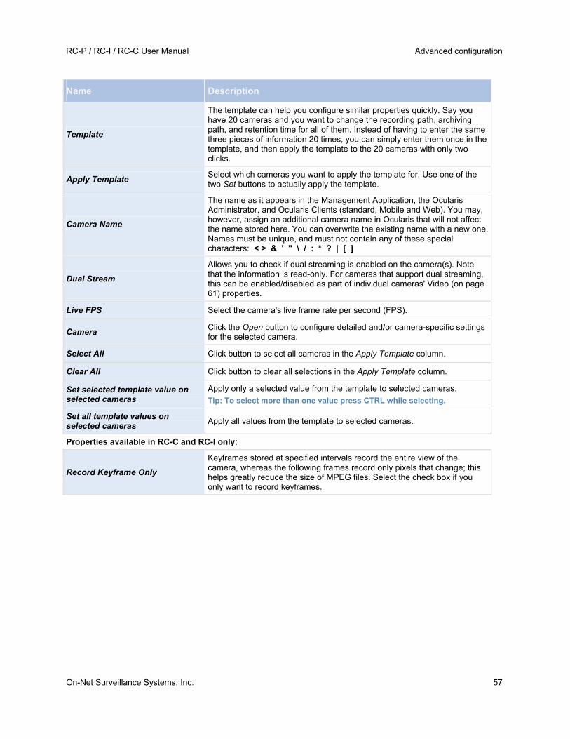
RC-P / RC-I / RC-C User Manual Advanced configuration
On-Net Surveillance Systems, Inc. 57
Name Description
Template
The template can help you configure similar properties quickly. Say you have 20 cameras and you want to change the recording path, archiving path, and retention time for all of them. Instead of having to enter the same three pieces of information 20 times, you can simply enter them once in the template, and then apply the template to the 20 cameras with only two clicks.
Apply Template Select which cameras you want to apply the template for. Use one of the two Set buttons to actually apply the template.
Camera Name
The name as it appears in the Management Application, the Ocularis Administrator, and Ocularis Clients (standard, Mobile and Web). You may, however, assign an additional camera name in Ocularis that will not affect the name stored here. You can overwrite the existing name with a new one. Names must be unique, and must not contain any of these special characters: < > & ' " \ / : * ? | [ ]
Dual Stream
Allows you to check if dual streaming is enabled on the camera(s). Note that the information is read-only. For cameras that support dual streaming, this can be enabled/disabled as part of individual cameras' Video (on page 61) properties.
Live FPS Select the camera's live frame rate per second (FPS).
Camera Click the Open button to configure detailed and/or camera-specific settings for the selected camera.
Select All Click button to select all cameras in the Apply Template column.
Clear All Click button to clear all selections in the Apply Template column.
Set selected template value on selected cameras
Apply only a selected value from the template to selected cameras.
Tip: To select more than one value press CTRL while selecting.
Set all template values on selected cameras
Apply all values from the template to selected cameras.
Properties available in RC-C and RC-I only:
Record Keyframe Only
Keyframes stored at specified intervals record the entire view of the camera, whereas the following frames record only pixels that change; this helps greatly reduce the size of MPEG files. Select the check box if you only want to record keyframes.

Advanced configuration RC-P / RC-I / RC-C User Manual
58 On-Net Surveillance Systems, Inc.
Record All Frames on
Allows you to make exceptions if you have selected to record keyframes only.
Motion Detection: Select this to record all frames when motion is detected. Two seconds after the last motion (see "Motion detection & exclude regions" on page 68) is detected, the camera will return to recording keyframes only.
Event: Select this to record all frames when an event occurs and until another event occurs. Requires that events have been defined, and that you select start and stop events in the neighboring columns.
Tip: If you have not yet defined any suitable events, you can quickly do it: use the Configure events list, located below the other fields.
Motion Detection & Event: Select this to record all frames when motion is detected, or when an event occurs and until another event occurs. Remember to select start and stop events in the neighboring columns.
Schedule only: Select this to record all frames according to the camera's speedup schedule (see "Speedup" on page 96) only.
Start Event Use when recording on Event or Motion Detection & Event. Select required start event. The camera will begin recording all frames when the start event occurs.
Stop Event Select required stop event. The camera will again only recording keyframes when the stop event occurs.
Audio recording
When you configure video and recording (see "About video and recording configuration" on page 42) for specific cameras, you can determine whether audio should be recorded or not. Your choice applies for all cameras on your RC-P / RC-I / RC-C system.
Name Description
Always Always record audio on all applicable cameras.
Never Never record audio on any cameras. Note that even though audio is never recorded, it is still be possible to listen to live audio in the Ocularis Client.
If you record audio, it is important that you note the following:
Audio recording affects video storage capacity: Audio is recorded to the associated camera’s database. Therefore, it is important to keep in mind that the database is likely to become full earlier if you record audio and video than if you only record video. The fact that the database becomes full is not in itself a problem since RC-P / RC-I / RC-C automatically archives (see "About archiving" on page 87) data if the database becomes full. However, you may need additional archiving space if you record audio.
o Example: If you use MPEG4, each one-second video GOP (Group Of Pictures) are stored in one record in the database. Each second of audio will also be stored in one record in the database. This reduces the database’s video storage capacity to half its capacity, because half of the database’s records is used for storing audio. Consequently, the database runs full sooner, and automatic archiving takes place more often than if you were only recording video.
o Example: If you use MJPEG, audio is stored in one record for every JPEG for as long as the audio block size does not exceed the time between the JPEGs. In extreme cases, this reduces the database’s video storage capacity to half its capacity, because half of the database’s records is used for storing audio. If

RC-P / RC-I / RC-C User Manual Advanced configuration
On-Net Surveillance Systems, Inc. 59
you use very high frame rates, which means less time between each JPEG, a smaller portion of the database is used for storing audio records, and consequently a larger portion is available for storing video. The result is that the database runs full sooner, and automatic archiving takes place more often than if you were only recording video.
Above examples are simplified. The exact available video storage capacity also depends on GOP/JPEG and audio kilobyte size.
Audio selection
When you configure video and recording (see "About video and recording configuration" on page 42), you can specify certain properties for many cameras in one step. Do this to speed up things, or because the properties in question are shared by all cameras rather than being specific to individual cameras. With a default microphone and/or speaker selected for a camera, audio from the microphone and/or speaker is automatically used when you view video from the camera. Note that all of the properties can also be specified individually for each camera.
Properties available in RC-P, RC-I and RC-C:
Name Description
Template
The template can help you configure similar properties quickly. Say you have 20 cameras and you want to change the recording path, archiving path, and retention time for all of them. Instead of having to enter the same three pieces of information 20 times, you can simply enter them once in the template, and then apply the template to the 20 cameras with only two clicks.
Apply Template Select which cameras you want to apply the template for. Use one of the two Set buttons to actually apply the template.
Camera Name
The name as it appears in the Management Application, the Ocularis Administrator, and Ocularis Clients (standard, Mobile and Web). You may, however, assign an additional camera name in Ocularis that will not affect the name stored here. You can overwrite the existing name with a new one. Names must be unique, and must not contain any of these special characters: < > & ' " \ / : * ? | [ ]
Default Microphone
Select a default microphone.
Tip: Note that you can select microphones attached to another hardware device than the selected camera.
Camera Click the Open button to configure detailed and/or camera-specific settings for the selected camera.
Select All Click button to select all cameras in the Apply Template column.
Clear All Click button to clear all selections in the Apply Template column.
Set selected template value on selected cameras
Apply only a selected value from the template to selected cameras.
Tip: To select more than one value press CTRL while selecting.
Set all template values on selected cameras
Apply all values from the template to selected cameras.
Only available in RC-C and RC-I:
Default Speaker Select a default speaker.

Advanced configuration RC-P / RC-I / RC-C User Manual
60 On-Net Surveillance Systems, Inc.
Storage information
The storage information lets you view how much storage space you have on your RC-P / RC-I / RC-C system—and, not least, how much of it is free:
Name Description
Drive Letter representing the drive in question, for example C:.
Path Path to where you save the files, for example C:\ or \\OurServer\OurFolder\OurSubfolder\.
Usage What the storage area is used for, for example recording or archiving.
Drive Size Total size of the drive.
Video Data Amount of video data on the drive.
Other Data Amount of other data on the drive.
Free Space Amount of unused space left on the drive.
Tip: To quickly view disk space usage in a pie chart format, select the line representing the drive you are interested in.
Camera properties
General
When you configure video and recording (see "About video and recording configuration" on page 42) for specific cameras, properties include:
Name Description
Enabled
Cameras are by default enabled, meaning that provided they are scheduled to be online (see "Online period" on page 95) and that they can to transfer video to RC-P / RC-I / RC-C. You can disable an individual camera, in which case no video/audio is transferred from the camera source to your system.
Preview Select this check box to show a preview of your camera's video. If you clear the check box, your system does not show a preview for your camera.
Camera Name
The name as it appears in the Management Application, the Ocularis Administrator, and Ocularis Clients (standard, Mobile and Web). You may, however, assign an additional camera name in Ocularis that will not affect the name stored here. You can overwrite the existing name with a new one. Names must be unique, and must not contain any of these special characters: < > & ' " \ / : * ? | [ ]
Camera shortcut number This field is not in use.
Note: These properties are to a large extent camera-specific. Since such properties vary from camera to camera, descriptions in the following are for guidance only. If you can access the selected camera, a live preview is displayed. Click the Camera Settings... button to open a separate window with properties for the selected camera.
The video properties typically let you control bandwidth, brightness, compression, contrast, resolution, rotation, and more by overwriting existing values of selecting new ones. When you adjust video settings, you can—for most cameras—preview the effect of your settings in an image below the fields.

RC-P / RC-I / RC-C User Manual Advanced configuration
On-Net Surveillance Systems, Inc. 61
Video settings may feature an Include Date and Time setting. If set to Yes, date and time from the camera are included in video. Note, however, that cameras are separate units which may have separate timing devices, power supplies, etc. Camera time and RC-P / RC-I / RC-C system time may therefore not correspond fully, and this may occasionally lead to confusion. As all frames are time-stamped by your system upon reception, and exact date and time information for each image is already known, it is recommended that the setting is set to No.
For consistent time synchronization, you may—if supported by the camera—automatically synchronize camera and system time through a time server.
Video
When you configure video and recording (see "About video and recording configuration" on page 42) for specific cameras, properties include:
If the camera uses MJPEG video format
With MJPEG, you can define frame rates for regular as well as speedup modes. If the camera offers dual stream, you can also enable this.
Note that there are three places where you can set frame rate:
Live Frame Rate - used for the regular recording stream
Live Frame Rate - used when speeding up recordings in connection with motion detection or similar functionality.
FPS (Frames per second) - used for the additional stream used for live viewing.
Regular frame rate mode:
Properties available for RC-P, RC-I and RC-C:
Name Description
Frame Rate Required average frame rate for video from the camera. Select number of frames, then select the time unit interval (second, minute or hour).
Properties available in RC-C and RC-I only:
Live Frame Rate
Required average frame rate for live video from the camera. Select number of frames, then select the time unit interval (second, minute or hour).
If the camera supports dual stream and dual stream is enabled, the Live Frame Rate column will be read-only with the value Dual streaming—which cannot be altered.
Recording Frame Rate
Required average frame rate for recorded video from the camera. Select number of frames, then select the time unit interval (second, minute or hour).The frame rate must be higher than the frame rate specified under normal mode.
Speedup frame rate mode:
Properties available in RC-P, RC-I and RC-C:
Name Description
Enable speedup frame rate The speedup feature lets you use a higher than normal frame rate if motion is detected and/or an event occurs. When you enable speedup, further columns for specifying speedup details become available.
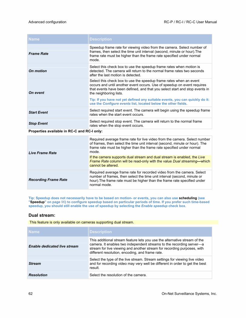
Advanced configuration RC-P / RC-I / RC-C User Manual
62 On-Net Surveillance Systems, Inc.
Name Description
Frame Rate
Speedup frame rate for viewing video from the camera. Select number of frames, then select the time unit interval (second, minute or hour).The frame rate must be higher than the frame rate specified under normal mode.
On motion Select this check box to use the speedup frame rates when motion is detected. The camera will return to the normal frame rates two seconds after the last motion is detected.
On event
Select this check box to use the speedup frame rates when an event occurs and until another event occurs. Use of speedup on event requires that events have been defined, and that you select start and stop events in the neighboring lists.
Tip: If you have not yet defined any suitable events, you can quickly do it: use the Configure events list, located below the other fields.
Start Event Select required start event. The camera will begin using the speedup frame rates when the start event occurs.
Stop Event Select required stop event. The camera will return to the normal frame rates when the stop event occurs.
Properties available in RC-C and RC-I only:
Live Frame Rate
Required average frame rate for live video from the camera. Select number of frames, then select the time unit interval (second, minute or hour). The frame rate must be higher than the frame rate specified under normal mode.
If the camera supports dual stream and dual stream is enabled, the Live Frame Rate column will be read-only with the value Dual streaming—which cannot be altered.
Recording Frame Rate
Required average frame rate for recorded video from the camera. Select number of frames, then select the time unit interval (second, minute or hour).The frame rate must be higher than the frame rate specified under normal mode.
Tip: Speedup does not necessarily have to be based on motion- or events, you can also use scheduling (see "Speedup" on page 96) to configure speedup based on particular periods of time. If you prefer such time-based speedup, you should still enable the use of speedup by selecting the Enable speedup check box.
Dual stream:
This feature is only available on cameras supporting dual stream.
Name Description
Enable dedicated live stream
This additional stream feature lets you use the alternative stream of the camera. It enables two independent streams to the recording server—a stream for live viewing and another stream for recording purposes, with different resolution, encoding, and frame rate.
Stream Select the type of the live stream. Stream settings for viewing live video and for recording video may very well be different in order to get the best result.
Resolution Select the resolution of the camera.

RC-P / RC-I / RC-C User Manual Advanced configuration
On-Net Surveillance Systems, Inc. 63
Name Description
FPS Select the camera's live frame rate per second (FPS)
If the camera uses MPEG video format
With MPEG, you can define frame rate and other settings:
Properties available in RC-P, RC-I and RC-C:
Name Description
Frame rate per second Frame rate for viewing live and recorded video from the camera. Select number of frames per second.
Properties available in RC-C and RC-I:
Record keyframes only
Keyframes stored at specified intervals record the entire view of the camera, whereas the following frames record only pixels that change. This helps greatly reducing the size of MPEG files. Select the check box if you only want to record keyframes. Note that you can specify exceptions if motion is detected or events occur.
Record all frames on motion
Allows you to make exceptions if you have selected to record keyframes only. Select this check box to record all frames when motion is detected. Two seconds after the last motion is detected, the camera will return to recording keyframes only.
Record all frames on event
Allows you to make exceptions if you have selected to record keyframes only. Select this check box to record all frames when an event occurs and until another event occurs. Use of this feature requires that events have been defined, and that you select start and stop events in the neighboring lists.
Tip: If you have not yet defined any suitable events, you can quickly do it: use the Configure events list, located below the other fields.
Start Event Use when recording on Event or Motion Detection & Event. Select required start event. The camera will begin recording all frames when the start event occurs.
Stop Event Select required stop event. The camera will again only recording keyframes when the stop event occurs.
Dual stream:
This feature is only available on cameras supporting dual stream.
Name Description
Enable dedicated live stream
This additional stream feature lets you use the alternative stream of the camera. It enables two independent streams to the recording server—a stream for live viewing and another stream for recording purposes, with different resolution, encoding, and frame rate.
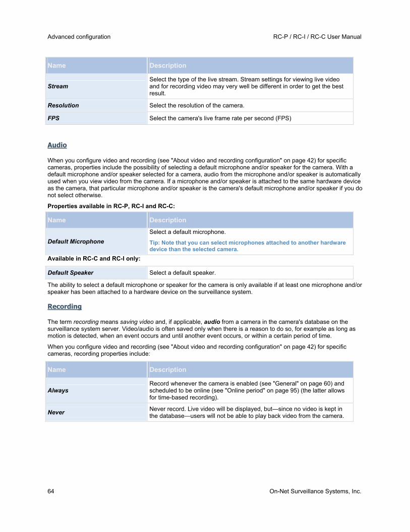
Advanced configuration RC-P / RC-I / RC-C User Manual
64 On-Net Surveillance Systems, Inc.
Name Description
Stream Select the type of the live stream. Stream settings for viewing live video and for recording video may very well be different in order to get the best result.
Resolution Select the resolution of the camera.
FPS Select the camera's live frame rate per second (FPS)
Audio
When you configure video and recording (see "About video and recording configuration" on page 42) for specific cameras, properties include the possibility of selecting a default microphone and/or speaker for the camera. With a default microphone and/or speaker selected for a camera, audio from the microphone and/or speaker is automatically used when you view video from the camera. If a microphone and/or speaker is attached to the same hardware device as the camera, that particular microphone and/or speaker is the camera's default microphone and/or speaker if you do not select otherwise.
Properties available in RC-P, RC-I and RC-C:
Name Description
Default Microphone
Select a default microphone.
Tip: Note that you can select microphones attached to another hardware device than the selected camera.
Available in RC-C and RC-I only:
Default Speaker Select a default speaker.
The ability to select a default microphone or speaker for the camera is only available if at least one microphone and/or speaker has been attached to a hardware device on the surveillance system.
Recording
The term recording means saving video and, if applicable, audio from a camera in the camera's database on the surveillance system server. Video/audio is often saved only when there is a reason to do so, for example as long as motion is detected, when an event occurs and until another event occurs, or within a certain period of time.
When you configure video and recording (see "About video and recording configuration" on page 42) for specific cameras, recording properties include:
Name Description
Always Record whenever the camera is enabled (see "General" on page 60) and scheduled to be online (see "Online period" on page 95) (the latter allows for time-based recording).
Never Never record. Live video will be displayed, but—since no video is kept in the database—users will not be able to play back video from the camera.

RC-P / RC-I / RC-C User Manual Advanced configuration
On-Net Surveillance Systems, Inc. 65
Name Description
Conditionally
Record when certain conditions are met. When you select this option, specify required conditions (see the following) which enables you to store recordings from periods preceding and following detected motion and/or specified events.
Example: If you have defined that video should be stored when a door is opened, being able to see what happened immediately prior to the door being opened may also be important. Say you have specified that video should be stored conditionally on event, with a start event called Door Opened and a stop event called Door Closed. With three seconds of pre-recording, video is recorded from three seconds before Door Opened occurs and until Door Closed occurs.
Built-in motion detection
Select this check box to record video in which motion (see "Motion detection & exclude regions" on page 68) is detected. Unless post-recording (see the following) is used, recording will stop immediately after the last motion is detected.
On event
Select this check box to record video when an event occurs and until another event occurs. Use of recording on event requires that events have been defined, and that you select start and stop events in the neighboring lists.
Tip: If you have not yet defined any suitable events, you can quickly do it: use the Configure events list, located below the other fields.
Start Event Select required start event. Recording will begin when the start event occurs (or earlier if using pre-recording; see the following).
Stop Event Select required stop event. Recording will end when the stop event occurs (or later if using post-recording; see the following).
Enable pre-recording Available only when the option Conditional is selected. Specify the number of seconds for which you want to record video from before recording start conditions (that is motion or start event) are met.
Enable post-recording Available only when the option Conditional is selected. Specify the number of seconds for which you want to record video after recording stop conditions (that is motion end or stop event) are met.
Note that manual recording (on page 53) may be enabled. With manual recording, users of Ocularis Client with the necessary rights (see "Configure user and group rights" on page 112) can manually start recording if they see something of interest while viewing live video from a camera which is not already recording. If enabled, manual recording can take place even if recording for individual cameras is set to Never or Conditionally.
Recording and archiving paths
When you configure video and recording (see "About video and recording configuration" on page 42) for specific cameras, properties include:

Advanced configuration RC-P / RC-I / RC-C User Manual
66 On-Net Surveillance Systems, Inc.
Component Requirement
Recording Path
Path to the folder in which the camera's database should be stored. Default is C:\MediaDatabase. To browse for another folder, click the browse icon next to the required cell. You can only specify a path to a folder on a local drive. You cannot specify a path to a network drive. If you use a network drive, it is not be possible to save recordings if the network drive becomes unavailable.
If you change the recording path, and you have existing recordings at the old location, you are asked whether you want to move the recordings to the new location (recommended), leave them at the old location, or delete them.
Tip: If you have several cameras, and several local drives are available, you can improve performance by distributing individual cameras' databases across several drives.
Delete Database
Click button to delete all recordings in the database for the camera. Archived recordings will not be affected.
IMPORTANT: Use with caution. All recordings in the database for the camera will be permanently
deleted. As a security measure, you are asked to confirm the deletion.
Archiving Path
Only editable if not using dynamic paths for archiving (see "About archiving" on page 87). Path to the folder in which the camera's archived recordings should be stored. Default is C:\MediaDatabase.
To browse for another folder, click the browse icon next to the relevant cell. If you change the archiving path, and there are existing archived recordings at the old location, you are asked whether you want to move the archived recordings to the new location (recommended), leave them at the old location, or delete them. Note that if you move archived recordings, RC-P / RC-I / RC-C will also archive what is currently in the camera database. In case you wonder why the camera database is empty just after you have moved archived recordings, this is the reason.
Delete Archives
Click button to delete all archived recordings for the camera. Recordings in the camera's regular database will not be affected. The ability to delete is available regardless of whether you use a single archiving path or dynamic archiving paths.
IMPORTANT: Use with caution. All archived recordings for the camera are permanently deleted. As a
security measure, you are asked to confirm the deletion.
Retention time
Total amount of time for which you want to keep recordings from the camera (that is, recordings in the camera's database as well as any archived recordings). Default is 7 days.
Retention time covers the total amount of time you want to keep recordings for. In earlier RC-P / RC-I / RC-C versions, time limits were specified separately for the database and archives.
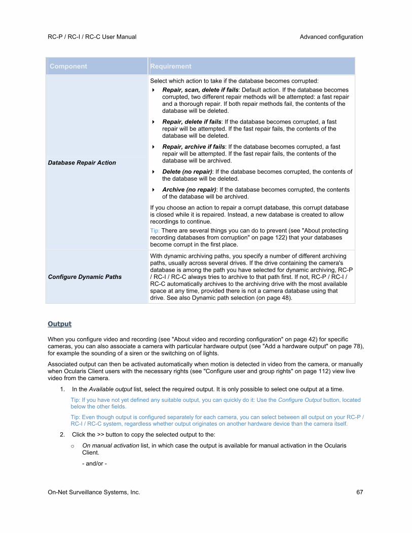
RC-P / RC-I / RC-C User Manual Advanced configuration
On-Net Surveillance Systems, Inc. 67
Component Requirement
Database Repair Action
Select which action to take if the database becomes corrupted:
Repair, scan, delete if fails: Default action. If the database becomes corrupted, two different repair methods will be attempted: a fast repair and a thorough repair. If both repair methods fail, the contents of the database will be deleted.
Repair, delete if fails: If the database becomes corrupted, a fast repair will be attempted. If the fast repair fails, the contents of the database will be deleted.
Repair, archive if fails: If the database becomes corrupted, a fast repair will be attempted. If the fast repair fails, the contents of the database will be archived.
Delete (no repair): If the database becomes corrupted, the contents of the database will be deleted.
Archive (no repair): If the database becomes corrupted, the contents of the database will be archived.
If you choose an action to repair a corrupt database, this corrupt database is closed while it is repaired. Instead, a new database is created to allow recordings to continue.
Tip: There are several things you can do to prevent (see "About protecting recording databases from corruption" on page 122) that your databases become corrupt in the first place.
Configure Dynamic Paths
With dynamic archiving paths, you specify a number of different archiving paths, usually across several drives. If the drive containing the camera's database is among the path you have selected for dynamic archiving, RC-P / RC-I / RC-C always tries to archive to that path first. If not, RC-P / RC-I / RC-C automatically archives to the archiving drive with the most available space at any time, provided there is not a camera database using that drive. See also Dynamic path selection (on page 48).
Output
When you configure video and recording (see "About video and recording configuration" on page 42) for specific cameras, you can also associate a camera with particular hardware output (see "Add a hardware output" on page 78), for example the sounding of a siren or the switching on of lights.
Associated output can then be activated automatically when motion is detected in video from the camera, or manually when Ocularis Client users with the necessary rights (see "Configure user and group rights" on page 112) view live video from the camera.
1. In the Available output list, select the required output. It is only possible to select one output at a time.
Tip: If you have not yet defined any suitable output, you can quickly do it: Use the Configure Output button, located below the other fields.
Tip: Even though output is configured separately for each camera, you can select between all output on your RC-P / RC-I / RC-C system, regardless whether output originates on another hardware device than the camera itself.
2. Click the >> button to copy the selected output to the:
o On manual activation list, in which case the output is available for manual activation in the Ocularis Client.
- and/or -

Advanced configuration RC-P / RC-I / RC-C User Manual
68 On-Net Surveillance Systems, Inc.
o On motion detected list, in which case the output is activated when motion is detected in video from the camera.
If required, the same output can appear on both lists.
3. Repeat for each required output.
If you later want to remove an output from the one of the lists, select the output in question, and click the << button.
Motion detection & exclude regions
When you configure video and recording (see "About video and recording configuration" on page 42) for specific cameras, adjusting motion detection is important because it may determine when video from the camera is recorded, when e-mail notifications are generated, when hardware output (such as lights or sirens) is activated, etc. Time spent on finding the best possible motion detection settings for each camera may help you later avoid unnecessary recordings, notifications, etc. Depending on the physical location of the camera, it may be a very good idea to test motion detection under different physical conditions (day/night, windy/calm weather, etc.).
Before you configure motion detection for a camera, you should configure the camera's video properties (see "General" on page 60), such as compression, resolution, etc.
Cameras that do not support multiple simultaneous video streams cannot connect to the surveillance server and the Management Application at the same time. Therefore, we recommend that you stop (see "Start and stop services" on page 116) the Recording Server service when you configure such devices for motion detection and PTZ.
Name Description
Enable Lets you enable or disable (see "About motion detection settings" on page 43) the built-in motion detection.
Show grid
Lets you toggle the grid on and off. Toggling the grid off may provide a less obscured view of the preview image; selection of areas which should be excluded from motion detection takes place the same way as when the grid is visible. When on, the preview image will be divided into small sections by a grid. To define areas which should be excluded from motion detection, drag the mouse over the areas in the preview image while pressing the mouse button down. Left mouse button selects a grid section; right mouse button clears a grid section. Selected areas are highlighted in blue.
Include All
Lets you quickly select all grid sections in the preview image. This can be useful if you want to exclude motion detection in most areas of the image, in which case you can simply clear the few sections in which you do not want to exclude motion detection.
Exclude All Lets you quickly clear all grid sections in the preview image.
Sensitivity
Determines how much each pixel must change before it is regarded as motion. With a high sensitivity, very little change in a pixel is required before it is regarded as motion. Areas in which motion is detected are highlighted in green in the preview image. Select a slider position in which only detections you consider motion are highlighted. The more you drag the slider to the left, the more of the preview image becomes highlighted. This is because with a high sensitivity even the slightest change in a pixel will be regarded as motion. As an alternative to using the slider, you may specify a value between 0 and 256 in the field next to the slider to control the sensitivity setting.
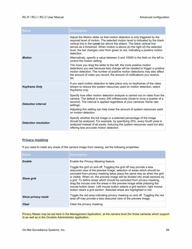
RC-P / RC-I / RC-C User Manual Advanced configuration
On-Net Surveillance Systems, Inc. 69
Name Description
Motion
Adjust the Motion slider so that motion detection is only triggered by the required level of motion. The selected motion level is indicated by the black vertical line in the Level bar above the sliders. The black vertical line serves as a threshold. When motion is above (to the right of) the selected level, the bar changes color from green to red, indicating a positive motion detection.
Alternatively, specify a value between 0 and 10000 in the field on the left to control the motion setting.
The more you drag the slider to the left, the more positive motion detections you see because less change will be needed to trigger a positive motion detection. The number of positive motion detections may also affect the amount of video you record, the amount of notifications you receive, etc.
Keyframe Only If you want motion detection to take place only on keyframes of the video stream to reduce the system resources used on motion detection, select Keyframe only.
Detection interval
Specify how often motion detection analysis is carried out on video from the camera. The default is every 240 milliseconds (close to once a quarter of a second). The interval is applied regardless of your cameras' frame rate settings.
Adjusting this setting can help lower the amount of system resources used on motion detection.
Detection resolution
Specify whether the full image or a selected percentage of the image should be analyzed. For example, by specifying 25%, every fourth pixel is analyzed instead of all pixels, reducing the system resources used but also offering less accurate motion detection.
Privacy masking
If you need to mask any areas of the camera image from viewing, set the following properties:
Name Description
Enable Enable the Privacy Masking feature.
Show grid
Toggle the grid on and off. Toggling the grid off may provide a less obscured view of the preview image; selection of areas which should be excluded from privacy masking takes place the same way as when the grid is visible. When on, the preview image will be divided into small sections by a grid. To define areas which should be excluded from privacy masking, drag the mouse over the areas in the preview image while pressing the mouse button down. Left mouse button selects a grid section; right mouse button clears a grid section. Selected areas are highlighted in red.
Show privacy mask Toggle the red area indicating privacy masking on and off. Toggling the red area off may provide a less obscured view of the preview image.
Clear Clear the privacy masking.
Privacy Masks may be set here in the Management Application, at the camera level (for those cameras which support it) as well as in the Ocularis Administrator application.

Advanced configuration RC-P / RC-I / RC-C User Manual
70 On-Net Surveillance Systems, Inc.
360° lens
360° lens technology allows you to view 360° panoramic video through an advanced lens. This is configured via Ocularis Administrator and not supported here.
PTZ preset positions
Available functionality depends on your product version.
PTZ-related properties are only available when you are dealing with a PTZ (pan-tilt-zoom) camera. You can use PTZ preset positions for making the PTZ camera automatically go to a particular position when particular events occur, and when setting up PTZ patrolling profiles. Preset positions can also be used in clients to allow users that have been given rights (see "Configure user and group rights" on page 112) to move the PTZ camera between preset positions. Names of preset positions must contain only the characters A-Z, a-z and the digits 0-9. If you import preset positions from cameras (see the following), verify that their names do not contain other characters. If they do, change the preset position names before you import them.
Cameras that do not support multiple simultaneous video streams cannot connect to the surveillance server and the Management Application at the same time. Therefore, we recommend that you stop (see "Start and stop services" on page 116) the Recording Server service when you configure such devices for motion detection and PTZ.
Name Description
PTZ type
Your configuration options depend on the type of PTZ camera in question:
Type 1 (stored on server): You define preset positions by moving the camera using the controls (see "Move PTZ type 1 and 3 to required positions" on page 46) in the upper half of the window, then storing each required position on the RC-P / RC-I / RC-C server. You can define up to 260 preset positions this way.
Type 2 (imported from camera): You import preset positions which have previously been defined and stored on the PTZ camera itself through the camera's own configuration interface. The number of allowed preset positions depends on the PTZ camera and driver used.
Type 3 (stored on camera): You define preset positions by moving the camera with the controls (see "Move PTZ type 1 and 3 to required positions" on page 46) in the upper half of the window, then storing each required position in the camera's own memory. You can define up to 260 preset positions this way. If preset positions have already been defined for the camera, you can simply import them for use with RC-P / RC-I / RC-C.
Import / Refresh
Only available when you have selected PTZ type 2 or 3. Lets you import already defined preset positions from the camera's memory for use with RC-P / RC-I / RC-C. If you have already imported preset positions this way, and preset positions have since then been added or changed on the camera, you can use this button to refresh the imported preset positions.
Add New
Only available when you have selected PTZ type 1. When you have move the camera to a required position using the controls in the upper half of the window, type a name for the position in the blank field, then click the button to add the position to the list of defined preset positions.
Remember that names of preset positions must contain only the characters A-Z, a-z and the digits 0-9.

RC-P / RC-I / RC-C User Manual Advanced configuration
On-Net Surveillance Systems, Inc. 71
Name Description
Set New Position
Only available when you have selected PTZ type 1 or 3. Lets you change an already defined preset position. In the list, select the preset position you want to change. Then move the camera to the new required position using the controls in the upper half of the window. Then click the button to overwrite the old position with the new one.
Delete
Only available when you have selected PTZ type 1 or 3. Lets you delete an already defined preset. In the list, select the preset position you want to delete, then click the button.
Before you delete a preset position, make sure it is not used in PTZ patrolling or PTZ on event. Since the preset positions are stored on the camera, you can bring a deleted preset position back into RC-P / RC-I / RC-C by clicking the Import / refresh button. If you bring back a preset position this way, and the preset position is to be used in PTZ patrolling or PTZ on event, you must manually configure PTZ patrolling and/or PTZ on event to use the preset position again.
Test Try out a preset position. In the list, select the preset position you want to test, then click the button to view the camera move to the selected position.
PTZ control wheel
Lets you move a preset position selected in the list up and down respectively. The selected preset position is moved one step per click. By moving preset positions up or down, you can control the sequence in which preset positions are presented in clients.
PTZ patrolling
PTZ-related properties are only available when you are dealing with a PTZ (pan-tilt-zoom) camera. PTZ patrolling is the continuous movement of a PTZ camera between a number of preset positions (see "PTZ preset positions" on page 70). To use patrolling, you should normally have specified at least two preset positions for the relevant PTZ camera.
To configure PTZ patrolling, select a patrolling profile in the Patrolling profiles list and specify relevant properties to define the exact behavior of the patrolling profile. When you have defined your patrolling profiles, remember to schedule (see "PTZ patrolling" on page 96) the use of patrolling profiles. Note that if users manually operate PTZ cameras, this can override patrolling.
Tip: You can specify a patrolling profile with only one preset if needed. Such a patrolling profile can be useful in two cases: For moving a PTZ camera to a specific position at a specific time, and for moving a PTZ camera to a specific position upon manual control of the PTZ camera.
Cameras that do not support multiple simultaneous video streams cannot connect to the surveillance server and the Management Application at the same time. Therefore, we recommend that you stop (see "Start and stop services" on page 116) the Recording Server service when you configure such devices for motion detection and PTZ.
Patrolling profiles
A PTZ camera may patrol according to several different patrolling profiles. For example, a PTZ camera in a supermarket may patrol according to one patrolling profile during opening hours, and according to another patrolling profile when the supermarket is closed.
From the Patrolling profiles list, select which patrolling profile to configure.
Add New: Add a new patrolling profile to the list. When you add a new patrolling profile, you can either give it a unique name, or reuse an existing name from another PTZ camera with PTZ patrolling.
Using several identically named patrolling profiles can be advantageous when you later configure scheduling. Example: If you have configured patrolling profiles identically named Night Patrolling on 25 different cameras,

Advanced configuration RC-P / RC-I / RC-C User Manual
72 On-Net Surveillance Systems, Inc.
you can schedule the use of Night Patrolling on all 25 cameras in one go, even though Night Patrolling covers individual preset positions on each of the 25 cameras.
Delete: Delete an existing patrolling profile. Note that the selected patrolling profile is removed from the list without further warning.
Preset positions to use in a patrolling profile
Having selected a patrolling profile in the Patrolling profiles list, you can specify which of the PTZ camera's preset positions should be used for the selected patrolling scheme:
1. In the Preset Positions list, select the preset positions you want to use. A preset position can be used more than once in a patrol scheme, for example if the preset position covers an especially important location.
Tip: By pressing the CTRL button on your keyboard while selecting from the Preset Positions list, you can select several or all of list's preset positions in one go.
2. Click the button to copy the selected preset positions to the Patrolling list.
3. The camera will move between preset positions in the sequence they appear in the Patrolling list, starting at the preset position listed first. If you want to change the sequence of preset positions in the Preset Positions list, select a preset position, and use the or buttons to move the selected preset position up or down in the list. The selected preset position is moved one step per click.
If you later want to remove a preset position from the Patrolling list, select the preset position in question, and click the button.
Wait and transition timing for a patrolling profile
Name Description
Wait time (sec.)
Specify the number of seconds for which the PTZ camera should stay at each preset position before it moves on to the next preset position. The default is 10 seconds. The wait time applies to all presets in the patrolling profile. The PTZ camera stays at each preset position for the same number of seconds.
Transition time (sec.)
Specify the number of seconds needed for the PTZ camera to move from one preset position to another. The default is five seconds. During this transition time, motion detection is automatically disabled, as irrelevant motion is otherwise likely to be detected while the camera moves between the preset positions. After the specified number of seconds, motion detection is automatically enabled again.
The transition time applies to all presets in the patrolling profile. It is important that the camera can switch between any of the patrolling profile's preset positions within the number of seconds you specify. If not, the system is likely to detect false motion. Note that it takes longer for the PTZ camera to move between positions that are located physically far apart (for example from an extreme left position to an extreme right position) than between positions that are located physically close together.
Tip: Note that wait time and transition time settings are tied to the selected patrolling profile. This allows you the flexibility of having different wait time and transition time settings for different patrolling profiles on the same camera.
Note: You can reuse the names of patrolling profiles defined for other cameras. This allows you to use a single patrolling profile name across several PTZ cameras, and can make scheduling (see "PTZ patrolling" on page 96) of PTZ patrolling much easier. Even though several PTZ cameras share a patrolling profile name, the movement between preset positions is individual for each camera.
RC-P / RC-I / RC-C User Manual Advanced configuration
On-Net Surveillance Systems, Inc. 73
PTZ scanning
PTZ scanning (continuous panning) is supported on a few PTZ cameras only.
PTZ scanning: Only available if your camera supports PTZ scanning. Lets you enable PTZ scanning and select a PTZ scanning speed from the list below the check box.
Note that PTZ scanning only works for PTZ type 1 cameras (where preset positions are configured and stored on the RC-P / RC-I / RC-C server). If the camera is a PTZ type 2 camera, and you import preset positions which have previously been defined and stored on the PTZ camera itself through the camera's own configuration interface, PTZ scanning will stop working. For more information about PTZ types, see PTZ preset positions (on page 70).
Pause PTZ patrolling
PTZ patrolling pauses automatically when users operate the camera manually as well if your system is using PTZ on Event (on page 73). If the system detects motion, it may also pause PTZ patrolling.
Tip: Note that pause settings are tied to the selected patrolling profile. This allows you the flexibility of having different pause settings for different patrolling profiles on the same camera.
Pause patrolling if motion is detected
To pause PTZ patrolling when the system detects motion, so that the PTZ camera remains at the position where the system detected motion for a specified period of time, do the following:
1. Select the Pause patrolling if motion is detected check box.
2. Select whether the PTZ camera should resume patrolling:
o After a certain number of seconds has passed since first detection of motion, regardless whether further motion is detected
or
o After a certain number of seconds has passed without further detection of motion
3. Specify the number of seconds for the selected option (default is ten and five seconds respectively).
4. Unless the transition time is set to zero, the system automatically disables motion detection while the camera moves between preset positions, as the system is likely to detect irrelevant motion otherwise while the camera moves between the preset positions.
Resume PTZ patrolling
The system automatically pauses PTZ patrolling when users operate the camera manually as well as if PTZ on Event is in use. You can specify how many seconds should pass before the system resumes regular patrolling after a manual or event-based interruption. The default is 30 seconds.
Apart from manual control, users of Ocularis Client can also stop a selected PTZ camera's patrolling entirely. For Ocularis Client users, the number of seconds specified in the Patrolling settings section therefore only applies when users manually control a PTZ camera and not when users stop a PTZ camera's patrolling entirely. When Ocularis Client users stop a PTZ camera's patrolling entirely, the camera's patrolling resumes only when the Ocularis Client user selects to resume it.
PTZ on event
PTZ-related properties are only available when you are dealing with a PTZ (pan-tilt-zoom) camera. When a PTZ camera supports preset positions (see "PTZ preset positions" on page 70), you can make the PTZ camera automatically go to a particular preset position when a particular event occurs.
When associating events with preset positions on a PTZ camera, you can select between all events defined on your system. You are not limited to selecting events defined on a particular hardware device.
1. In the Events list in the left side of the window, select the relevant event.
Advanced configuration RC-P / RC-I / RC-C User Manual
74 On-Net Surveillance Systems, Inc.
2. In the PTZ Preset Position list in the right side of the window, select the relevant preset position. For this purpose, you can only use an event once per PTZ camera. However, use different events for making the PTZ camera go to the same preset position. Example:
o Event 1 makes the PTZ camera go to preset position A
o Event 2 makes the PTZ camera go to preset position B
o Event 3 makes the PTZ camera go to preset position A
If later you want to end the association between a particular event and a particular preset position, clear the field containing the event.
After you have made the PTZ setting changes, restart services (see "Start and stop services" on page 116).
Cameras that do not support multiple simultaneous video streams cannot connect to the surveillance server and the Management Application at the same time. Therefore, we recommend that you stop (see "Start and stop services" on page 116) the Recording Server service when you configure such devices for motion detection and PTZ.
Microphones
About microphones
In your system, Microphones are typically attached to hardware devices, and therefore physically located next to cameras. Operators, with the necessary rights, can then listen to recordings through the Ocularis Client (provided the computer running the Ocularis Client has speakers attached). You manage microphones in RC-P / RC-I / RC-C, meaning you can always manage the microphones attached to cameras, not microphones attached to Ocularis Client operators' computers.
If you have added more microphones to your system than you need, you can hide the ones you do not need by right-clicking the relevant microphone or speaker and select Hide. If you need the hidden microphone again, you can right-click the overall microphone icon and select Show Hidden Items.
Configure microphones or speakers
1. In the Management Application's navigation pane, expand Advanced Configuration, expand Hardware Devices, and expand the hardware device to which the relevant microphone or speaker is attached.
2. Right-click the relevant microphone or speaker, and select Properties.
3. Specify properties (see "Speaker properties" on page 42) as required.
Configuration of microphones and speakers in RC-P / RC-I / RC-C is very basic. Settings such as volume, etc. are controlled on the microphone or speaker units themselves.
Show or hide microphones or speakers
Available functionality depends on your product version.
If you have added more microphones or speakers to your system than you need, you can hide the ones you do not need by right-clicking the relevant microphone or speaker and select Hide. If you need the hidden microphone/speaker again, you can right-click the overall microphone or speaker icon and select Show Hidden Items.
Microphone (properties)
When you configure video and recording (see "About video and recording configuration" on page 42) for specific cameras, you can determine when audio should be recorded or not. Your choice applies for all cameras on your RC-P / RC-I / RC-C system.

RC-P / RC-I / RC-C User Manual Advanced configuration
On-Net Surveillance Systems, Inc. 75
Microphone properties
Enabled
Microphones are by default enabled, meaning that they are able to transfer audio to RC-P / RC-I / RC-C. If needed, you can disable an individual microphone, in which case no audio is transferred from the microphone to RC-P / RC-I / RC-C.
Name
The name as it appears in the Management Application, the Ocularis Administrator, and Ocularis Clients (standard, Mobile and Web). You may, however, assign an additional camera name in Ocularis that will not affect the name stored here. You can overwrite the existing name with a new one. Names must be unique, and must not contain any of these special characters: < > & ' " \ / : * ? | [ ]
On some hardware devices, audio can also be enabled/disabled on the hardware device itself, typically through the hardware device's own configuration web page. If audio on a hardware device does not work after enabling it in the Management Application, you should verify whether the problem may be due to audio being disabled on the hardware device itself.
Recording settings
Name Description
Always Always record audio on all applicable cameras.
Follow video Record audio only when video is recorded.
Never Never record audio on any cameras. Note that even though audio is never recorded, it is still be possible to listen to live audio in the Ocularis Client.
Events and output
About input and output
Hardware input, such as door sensors, can be attached to input ports on hardware devices. Input from such external hardware input units can be used for generating events in RC-P / RC-I / RC-C.
Hardware output units can be attached to output ports on many hardware devices, allowing you to activate lights, sirens, and more from RC-P / RC-I / RC-C. Such hardware output can be activated automatically by events, or manually from clients.
Before you specify use of hardware input and hardware output units on a hardware device, verify the hardware device recognized the sensor operation. Most hardware devices are capable of showing this in their configuration interfaces, or via CGI script commands.
You do not have to configure hardware input units separately. Any hardware input units connected to hardware devices are automatically detected when you add the hardware devices to RC-P / RC-I / RC-C. The same goes for hardware output, but hardware output does require some simple configuration in RC-P / RC-I / RC-C.
If you want to configure hardware output and automatically trigger output when events occur, so that, for example, lights are switched on when a door is opened or when motion is detected in video, see Add a hardware output (on page 78) and Configure hardware output on event (on page 79).
About events and output
Events and output of various types can be used for automatically triggering actions in RC-P / RC-I / RC-C. Examples of actions: starting or stopping recording on cameras, switching to a particular video frame rate, triggering

Advanced configuration RC-P / RC-I / RC-C User Manual
76 On-Net Surveillance Systems, Inc.
notifications, making PTZ cameras move to specific preset positions, etc. Events can also be used for activating hardware output. You can also configure events and output to generate alerts.
Events can be divided in to:
Internal events (system-related): for example, motion, server responding/not responding, archiving problems, lack of disk space, etc.
External events (integrated): for use with third party applications.
Events may be configured here in the Management Application as well as in Ocularis through the Ocularis Administrator application. Depending on the event, you may benefit more from configuring the event in Ocularis.
Overview of events and output
Types of events:
Name Description
Hardware input events:
Hardware input, such as door sensors, can be attached to input ports on hardware devices. Input from such external hardware input units can be used for generating events in RC-P / RC-I / RC-C.
Events based on input from hardware input units attached to hardware devices are called hardware input events.
Some hardware devices have their own capabilities for detecting motion, for detecting moving and/or static objects, etc. (configured in the hardware devices' own software, typically by accessing a browser-based configuration interface on the hardware device's IP address). When this is the case, RC-P / RC-I / RC-C considers such detections as input from the hardware, and you can use such detections as input events as well.
Lastly, hardware input events can be based on RC-P / RC-I / RC-C detecting motion in video from a camera, based on motion detection settings in RC-P / RC-I / RC-C.
This type of hardware input events is also called system motion detection events or VMD (Video Motion Detection) events. In earlier RC-P / RC-I / RC-C versions, VMD events were an event type of their own. Now, they are considered a type of hardware input event.
Hardware output:
Hardware output units can be attached to output ports on many hardware devices, allowing you to activate lights, sirens, and more from RC-P / RC-I / RC-C. Such hardware output can be activated automatically by events, or manually from clients.
Manual events:
Events may be generated manually by the users selecting them in their clients. These events are called manual events.
Manual events can be of the type Global events or Timer events:
Global events apply to all hardware whereas timer events are separate events, triggered by the hardware input event, manual event or generic event under which they are defined. Timer events occur a specified number of seconds or minutes after the event, under which they are defined, has occurred. Timer events may be used for a wide variety of purposes, typically for stopping previously triggered actions.
Example:
A camera starts recording based on a hardware input event, for example when a door is opened. A timer event stops the recording after 15 seconds.

RC-P / RC-I / RC-C User Manual Advanced configuration
On-Net Surveillance Systems, Inc. 77
Name Description
Generic events: Input may also be received in the form of TCP or UDP data packages, which can be analyzed by RC-I / RC-C, and—if they match specified criteria—used to generate events. Such events are called generic events.
Output control on event:
Hardware output can be activated automatically when events occur. For example, when a door is opened (hardware input event), lights are switched on (hardware output).
When configuring the output control, you can select between all output and events defined in RC-P / RC-I / RC-C. You are not limited to selecting output or events defined on particular hardware devices. You can use a single event for activating more than one output.
Before you configure events of any type, configure general event handling, such as which ports RC-P / RC-I / RC-C should use for event data. Normally, you can just use the default values, but it is a good idea to verify that your organization is not already using the ports for other purposes. See Configure general event handling (on page 80).
Before you specify use of hardware input and hardware output units on a hardware device, verify that sensor operation is recognized by the hardware device. Most hardware devices are capable of showing this in their configuration interfaces, or via CGI script commands.
You do not have to configure hardware input units separately, any hardware input units connected to hardware devices are automatically detected when you add the hardware devices to RC-P / RC-I / RC-C. The same goes for hardware output, but hardware output does require some simple configuration in RC-P / RC-I / RC-C.
If you want to configure hardware output and automatically trigger output when events occur, so that, for example, lights are switched on when a door is opened or when motion is detected in video, see Add a hardware output (on page 78) and Configure hardware output on event (on page 79).
When you are ready to configure events, see Add a hardware input event (on page 77), Add a generic event (on page 79), and Add a manual event (on page 78). If you want to use timer events with your other events, see Add a timer event (on page 79).
Add a hardware input event
With hardware input events, you can turn input received from input units attached to hardware devices into events in RC-P / RC-I / RC-C.
Before you specify input for a hardware device, verify the hardware device recognizes sensor operation. Most hardware devices can show this in their configuration interfaces, or via CGI script commands. Also check the release notes to verify that input-controlled operation is supported for the hardware device and firmware used.
To add and/or configure a hardware input event, do the following:
1. In the Management Application navigation pane, expand Advanced Configuration, then expand Events and Output. Right-click Hardware Input Events and select Enable New Input Event.
2. In the Hardware Input Event Properties window's list of hardware devices, expand the required hardware device to see a list of pre-defined hardware input.
3. Select the required types of input to use them as events. The types of input often vary from camera to camera. If motion detection (see "Motion detection & exclude regions" on page 68) is enabled in RC-P / RC-I / RC-C for the camera in question, note the input type System Motion Detection, which lets you turn detected motion in the camera's video stream into an event. In earlier RC-P / RC-I / RC-C versions, this was known as a VMD event.
Note that some types of input are mutually exclusive. When you select one type of input, you may therefore note that other types of input become unavailable for selection.
4. For each selected type of input, select required properties (see "Hardware input event" on page 80). When ready, click OK, or click the Add button to add a timer event (on page 79) to the event you have just created.
5. Save your configuration changes by clicking Save in the yellow notification bar in the upper-right corner of the Management Application.

Advanced configuration RC-P / RC-I / RC-C User Manual
78 On-Net Surveillance Systems, Inc.
Add a hardware output
With hardware output, you can add external output units, such as lights, sirens, door openers, etc., to your RC-P / RC-I / RC-C system. Once added, output can be activated automatically by events or detected motion, or manually by client users.
Before you specify output, verify that sensor operation is recognized by the hardware device with which you are going to use the output. Most hardware devices are capable of showing this in their configuration interfaces, or via CGI script commands. Also check the release notes to verify that output-controlled operation is supported for the hardware device and firmware used.
To add a hardware output event, do the following:
1. In the Management Application navigation pane, expand Advanced Configuration, then expand Events and Output. Right-click Hardware Output and select Add New Output.
2. In the Hardware Output Properties window's list of hardware devices, select the required hardware device, and click the Add button below the list.
3. Specify required properties (see "Hardware input event" on page 80).
4. Click OK.
5. Save your configuration changes by clicking Save in the yellow notification bar in the upper-right corner of the Management Application.
For information about how to configure automatic activation of hardware output when events occur, see Configure hardware output on event (on page 79). You configure output for manual activation in clients as well as for automatic activation on detected motion individually for each camera (see "Output" on page 67).
Add a manual event
With manual events, your users with required rights (see "Configure user and group rights" on page 112) can trigger events manually from their clients. Manual events can be global (shared by all cameras) or tied to a particular camera (only available when the camera is selected). You can use manual events for a wide variety of purposes, for example:
As start and stop events for use when scheduling cameras' online periods (see "Online period" on page 95). For example, you can make a camera start or stop transferring video to the surveillance system based on a manual event.
As start and stop events for controlling other camera settings. For example, you can make a camera use a higher frame rate based on a manual event or you can use a manual event for triggering PTZ on event (on page 73).
For triggering output. Particular output can be associated (see "Configure hardware output on event" on page 79) with manual events.
For triggering event-based notifications (see "About notifications" on page 100).
In combinations. For example, a manual event could make a camera start transferring video to the surveillance system while an output is triggered and an e-mail notification is sent to relevant people.
To add a manual event, do the following:
1. In the Management Application navigation pane, expand Advanced Configuration, then expand Events and Output. Right-click Manual Events and select Add New Manual Event
2. In the list in the left side of the Manual Event Properties, select global or a camera as required.
3. Click the add button and specify required properties (see "Hardware input event" on page 80). When ready, click OK, or click the Add button again to add a timer event (on page 79) to the event you have just created.
4. Save your configuration changes by clicking Save in the yellow notification bar in the upper-right corner of the Management Application.

RC-P / RC-I / RC-C User Manual Advanced configuration
On-Net Surveillance Systems, Inc. 79
Add a generic event
RC-C and RC-I can analyze received TCP and/or UDP data packages, and automatically trigger events when specified criteria are met. This way, you can easily integrate the system with a very wide range of external sources, for example access control systems and alarm systems and more. Events based on the analysis of received TCP and/or UDP packets are called generic events.
1. In the Management Application navigation pane, expand Advanced Configuration, then expand Events and Output. Right-click Generic Events and select Add New Generic Event.
2. In the Generic Event Properties window, click the Add button, and specify required properties (see "Generic event" on page 83). When ready, click OK, or click the Add button to add a timer event to the event you have just created.
3. Save your configuration changes by clicking Save in the yellow notification bar in the upper-right corner of the Management Application.
Generic Events may also be configured in the Ocularis Administrator application for all models including Ocularis PS.
Add a timer event
Timer events are separate events, triggered by the type of event under which they are defined. Timer events occur a specified number of seconds or minutes after the event under which they are defined has occurred. Timer events may be used for a wide variety of purposes, typically for stopping previously triggered actions. Examples:
A camera starts recording based on a hardware input event, for example when a door is opened. A timer event stops the recording after 15 seconds
Lights are switched on and a camera starts recording based on a manual event. A timer event stops the recording after one minute, and another timer event switches the lights off after two minutes
To add a timer event, select any event you have previously configured, click the Add button, and specify required properties (see "Timer event" on page 83). Your system comes with two simple schedule profiles, Always on and Always off, which you cannot edit or delete. If these do not meet your needs, you can create any number of customized schedule profiles for each camera. You can reuse a customized schedule profile for more than one purpose if you want to. Save your configuration changes by clicking Save in the yellow notification bar in the upper-right corner of the Management Application.
Tip: You can add as many timer events as required under an event. This way, you can, for example, make one timer event trigger something 10 seconds after the main event, another timer event trigger something else 30 seconds after the main event, and a third timer event trigger something else 2 minutes after the main event.
Configure hardware output on event
Once you have added hardware output (see "Add a hardware output" on page 78), such as lights, sirens, door openers, etc., you can associate the hardware output with events. This way, particular hardware output can be activated automatically when events occur. Example: When a door is opened (hardware input event), lights are switched on (hardware output).
When making the associations, you can select between all output and events defined on your RC-P / RC-I / RC-C server. You are not limited to selecting output or events defined on particular hardware devices.
1. In the Management Application's navigation pane, expand Advanced Configuration, then expand Events and Output. Right-click Output Control on Event and select Properties.
2. Fill in the relevant properties (see "Output control on event (Events and Output-specific properties)" on page 87).
3. Click OK.
4. Save your configuration changes by clicking Save in the yellow notification bar in the upper-right corner of the Management Application.

Advanced configuration RC-P / RC-I / RC-C User Manual
80 On-Net Surveillance Systems, Inc.
You can use a single event for activating more than one output. You cannot delete associations, but you can change your selections or select None in both columns as required.
Tip: If you have not yet defined any suitable event or output, you can quickly do it: Use the Configure events list and/or Configure Output... button, located below the list of associations.
Configure general event handling
Before configuring events of any type, configure general event handling, such as which ports RC-P / RC-I / RC-C should use for event data. Normally, you can just use the default values, but it is a good idea to verify that your organization is not already using the ports for other purposes.
1. In the Management Application's navigation pane, expand Advanced Configuration, right-click Events and Output, and select Properties.
2. Specify required properties (see "Ports and polling" on page 80). Your system comes with two simple schedule profiles, Always on and Always off, which you cannot edit or delete. If these do not meet your needs, you can create any number of customized schedule profiles for each camera. You can reuse a customized schedule profile for more than one purpose if you want to.
3. Save your configuration changes by clicking Save in the yellow notification bar in the upper-right corner of the Management Application.
General event properties
Ports and polling
The General Event Properties window lets you specify network settings to be used in connection with event handling.
Name Description
Alert and generic event port Specify port number to use for handling events. Default port is port 1234.
SMTP event port Specify port number to use for sending event information from hardware devices to RC-P / RC-I / RC-C via SMTP. Default port is port 25.
FTP event port Port to use for FTP communication with the hardware device. Default port is port 21.
Polling interval [1/10] second
For a small number of hardware devices, primarily dedicated input/output devices (see "About dedicated input/output devices" on page 37), it is necessary for RC-P / RC-I / RC-C to regularly check the state of the hardware devices' input ports in order to detect input. Such state checking at regular intervals is called polling. You can specify (in tenths of a second) the interval between state checks. Default value is 10 tenths of a second (that is one second). For dedicated input/output devices, it is highly recommended that the polling frequency is set to the lowest possible value (one tenth of a second between state checks). For information about which hardware devices require polling, see the release note.
Events and output properties
Hardware input event
When you add hardware input events (see "Add a hardware input event" on page 77), some properties depend on the selected type of input:
Properties available in RC-P, RC-I and RC-C:
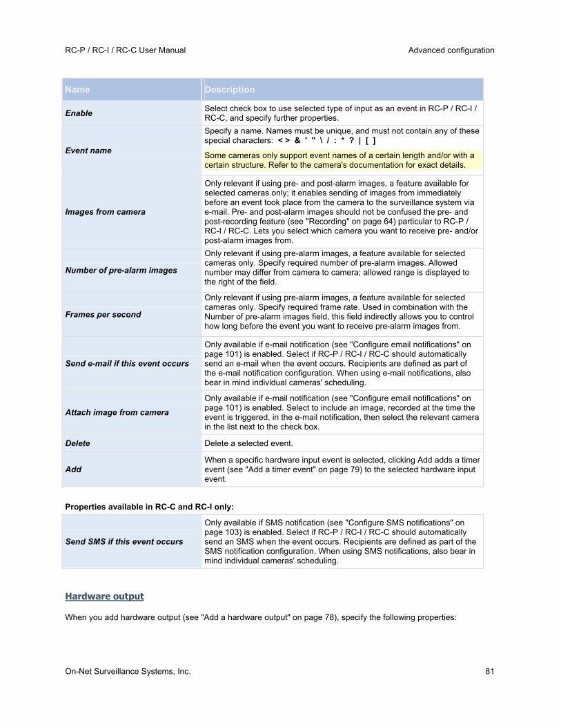
RC-P / RC-I / RC-C User Manual Advanced configuration
On-Net Surveillance Systems, Inc. 81
Name Description
Enable Select check box to use selected type of input as an event in RC-P / RC-I / RC-C, and specify further properties.
Event name
Specify a name. Names must be unique, and must not contain any of these special characters: < > & ' " \ / : * ? | [ ]
Some cameras only support event names of a certain length and/or with a certain structure. Refer to the camera's documentation for exact details.
Images from camera
Only relevant if using pre- and post-alarm images, a feature available for selected cameras only; it enables sending of images from immediately before an event took place from the camera to the surveillance system via e-mail. Pre- and post-alarm images should not be confused the pre- and post-recording feature (see "Recording" on page 64) particular to RC-P / RC-I / RC-C. Lets you select which camera you want to receive pre- and/or post-alarm images from.
Number of pre-alarm images
Only relevant if using pre-alarm images, a feature available for selected cameras only. Specify required number of pre-alarm images. Allowed number may differ from camera to camera; allowed range is displayed to the right of the field.
Frames per second
Only relevant if using pre-alarm images, a feature available for selected cameras only. Specify required frame rate. Used in combination with the Number of pre-alarm images field, this field indirectly allows you to control how long before the event you want to receive pre-alarm images from.
Send e-mail if this event occurs
Only available if e-mail notification (see "Configure email notifications" on page 101) is enabled. Select if RC-P / RC-I / RC-C should automatically send an e-mail when the event occurs. Recipients are defined as part of the e-mail notification configuration. When using e-mail notifications, also bear in mind individual cameras' scheduling.
Attach image from camera
Only available if e-mail notification (see "Configure email notifications" on page 101) is enabled. Select to include an image, recorded at the time the event is triggered, in the e-mail notification, then select the relevant camera in the list next to the check box.
Delete Delete a selected event.
Add When a specific hardware input event is selected, clicking Add adds a timer event (see "Add a timer event" on page 79) to the selected hardware input event.
Properties available in RC-C and RC-I only:
Send SMS if this event occurs
Only available if SMS notification (see "Configure SMS notifications" on page 103) is enabled. Select if RC-P / RC-I / RC-C should automatically send an SMS when the event occurs. Recipients are defined as part of the SMS notification configuration. When using SMS notifications, also bear in mind individual cameras' scheduling.
Hardware output
When you add hardware output (see "Add a hardware output" on page 78), specify the following properties:
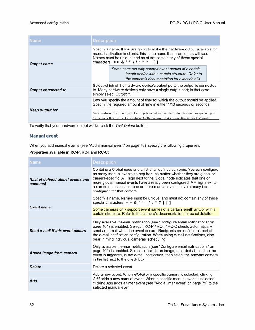
Advanced configuration RC-P / RC-I / RC-C User Manual
82 On-Net Surveillance Systems, Inc.
Name Description
Output name
Specify a name. If you are going to make the hardware output available for manual activation in clients, this is the name that client users will see. Names must be unique, and must not contain any of these special characters: < > & ' " \ / : * ? | [ ]
Some cameras only support event names of a certain length and/or with a certain structure. Refer to the camera's documentation for exact details.
Output connected to Select which of the hardware device's output ports the output is connected to. Many hardware devices only have a single output port; in that case simply select Output 1.
Keep output for
Lets you specify the amount of time for which the output should be applied. Specify the required amount of time in either 1/10 seconds or seconds.
Some hardware devices are only able to apply output for a relatively short time, for example for up to
five seconds. Refer to the documentation for the hardware device in question for exact information.
To verify that your hardware output works, click the Test Output button.
Manual event
When you add manual events (see "Add a manual event" on page 78), specify the following properties:
Properties available in RC-P, RC-I and RC-C:
Name Description
[List of defined global events and cameras]
Contains a Global node and a list of all defined cameras. You can configure as many manual events as required, no matter whether they are global or camera-specific. A + sign next to the Global node indicates that one or more global manual events have already been configured. A + sign next to a camera indicates that one or more manual events have already been configured for that camera.
Event name
Specify a name. Names must be unique, and must not contain any of these special characters: < > & ' " \ / : * ? | [ ]
Some cameras only support event names of a certain length and/or with a certain structure. Refer to the camera's documentation for exact details.
Send e-mail if this event occurs
Only available if e-mail notification (see "Configure email notifications" on page 101) is enabled. Select if RC-P / RC-I / RC-C should automatically send an e-mail when the event occurs. Recipients are defined as part of the e-mail notification configuration. When using e-mail notifications, also bear in mind individual cameras' scheduling.
Attach image from camera
Only available if e-mail notification (see "Configure email notifications" on page 101) is enabled. Select to include an image, recorded at the time the event is triggered, in the e-mail notification, then select the relevant camera in the list next to the check box.
Delete Delete a selected event.
Add
Add a new event. When Global or a specific camera is selected, clicking Add adds a new manual event. When a specific manual event is selected, clicking Add adds a timer event (see "Add a timer event" on page 79) to the selected manual event.

RC-P / RC-I / RC-C User Manual Advanced configuration
On-Net Surveillance Systems, Inc. 83
Properties available in RC-C and RC-I only:
Send SMS if this event occurs
Only available if SMS notification (see "Configure SMS notifications" on page 103) is enabled. Select if RC-P / RC-I / RC-C should automatically send an SMS when the event occurs. Recipients are defined as part of the SMS notification configuration. When using SMS notifications, also bear in mind individual cameras' scheduling.
Timer event
When you add timer events (see "Add a timer event" on page 79), specify the following properties:
Name Description
Timer event name
Specify a name. Names must be unique, and must not contain any of these special characters: < > & ' " \ / : * ? | [ ]
Some cameras only support event names of a certain length and/or with a certain structure. Refer to
the camera's documentation for exact details.
Timer event occurs after Specify the amount of time that should pass between the main event occurring and the timer event (in seconds or minutes).
Generic event
When you add generic events, specify the following properties (RC-C and RC-I only):
Name Description
Event name
Specify a name. Names must be unique, and must not contain any of these special characters: < > & ' " \ / : * ? | [ ]
Some cameras only support event names of a certain length and/or with a certain structure. Refer to the camera's documentation for exact details.
Event port
Read-only field displaying the port number on which RC-C OR RC-I listens for generic events (default is port 1234). The port number can be changed as part of the general event handling configuration (see "Configure general event handling" on page 80).
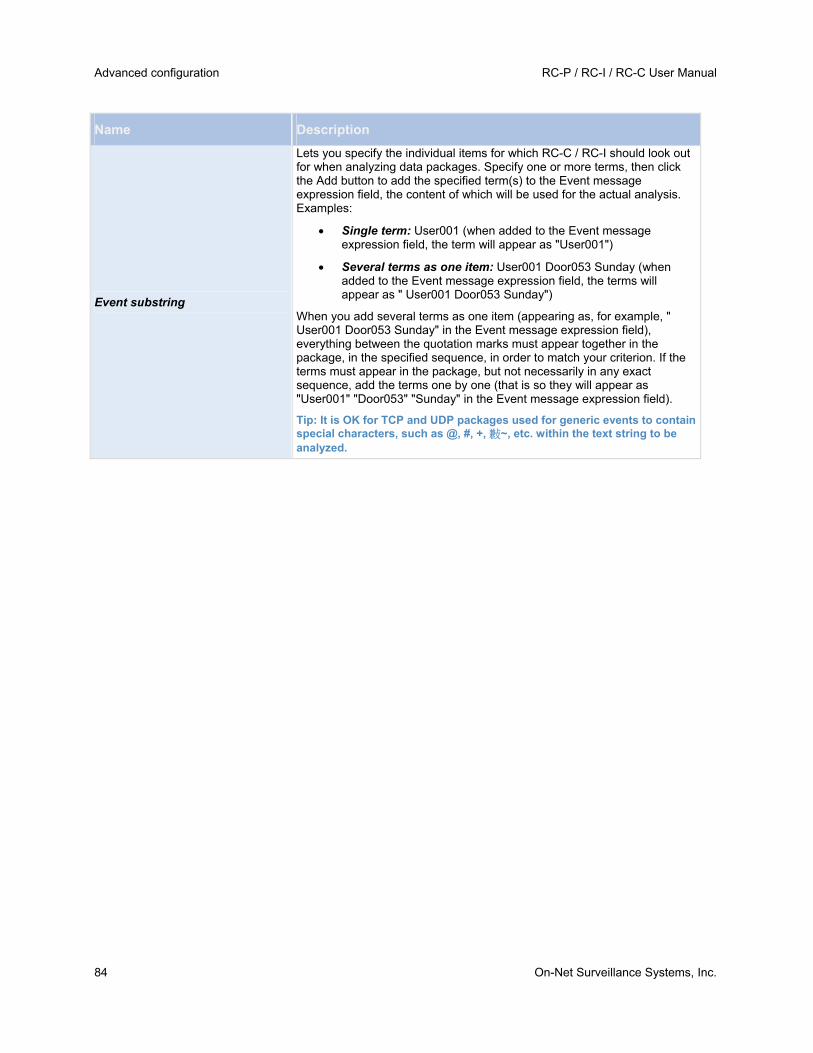
Advanced configuration RC-P / RC-I / RC-C User Manual
84 On-Net Surveillance Systems, Inc.
Name Description
Event substring
Lets you specify the individual items for which RC-C / RC-I should look out for when analyzing data packages. Specify one or more terms, then click the Add button to add the specified term(s) to the Event message expression field, the content of which will be used for the actual analysis. Examples:
Single term: User001 (when added to the Event message expression field, the term will appear as "User001")
Several terms as one item: User001 Door053 Sunday (when added to the Event message expression field, the terms will appear as " User001 Door053 Sunday")
When you add several terms as one item (appearing as, for example, " User001 Door053 Sunday" in the Event message expression field), everything between the quotation marks must appear together in the package, in the specified sequence, in order to match your criterion. If the terms must appear in the package, but not necessarily in any exact sequence, add the terms one by one (that is so they will appear as "User001" "Door053" "Sunday" in the Event message expression field).
Tip: It is OK for TCP and UDP packages used for generic events to contain special characters, such as @, #, +, 㪠~, etc. within the text string to be analyzed.

RC-P / RC-I / RC-C User Manual Advanced configuration
On-Net Surveillance Systems, Inc. 85
Name Description
Event message expression
Displays the string which will be used for the actual package analysis. The field is not directly editable. However, you can position the cursor inside the field in order to determine where a new item should be included when you click the Add button or one of the parenthesis or operator buttons described in the following. Likewise, you can position the cursor inside the field in order to determine where an item should be removed when clicking the Remove button: The item immediately to the left of the cursor will be removed when you click the Remove button.
(: Lets you add a start parenthesis character to the Event message expression field. Parentheses can be used to ensure that related terms are processed together as a logical unit; in other words, they can be used to force a certain processing order in the analysis. Example: If using ("User001" OR "Door053") AND "Sunday", the two terms inside the parenthesis will be processed first, then the result will be combined with the last part of the string. In other words, RC-C / RC-I will first look for any packages containing either of the terms User001 or Door053, then it will take the results and run through them in order to see which packages also contain the term Sunday.
): Lets you add an end parenthesis character to the Event message expression field.
AND: Lets you add an AND operator to the Event message expression field. With an AND operator, you specify that the terms on both sides of the AND operator must be present. Example: If using User001 AND Door053 AND Sunday, the term User001 as well as the term Door053 as well as the term Sunday must be present in order for the criterion to be met. It is not enough for only one or two of the terms to be present. As a rule of thumb, the more terms you combine with AND, the fewer results you will retrieve.
OR: Lets you add an OR operator to the Event message expression field. With an OR operator, you specify that either one or another term must be present. Example: If using User001 OR Door053 OR Sunday, the term User001 or the term Door053 or the term Sunday must be present in order for the criterion to be met. The criterion is satisfied even if only one of the terms is present. As a rule of thumb, the more terms you combine with OR, the more results you will retrieve.
Remove: Lets you remove the item immediately to the left of a cursor positioned in the Event message expression field. If you have not positioned the cursor in the Event message expression field, the last item in the field will be removed.

Advanced configuration RC-P / RC-I / RC-C User Manual
86 On-Net Surveillance Systems, Inc.
Name Description
Event priority
The same data package may be analyzed for different events. The ability to assign a priority to each event lets you manage which event should be triggered if a received package matches the criteria for several events. The priority must be specified as a number between 0 (lowest priority) and 1000 (highest priority). When RC-C / RC-I receives a TCP and/or UDP package, analysis of the packet will start with analysis for the event with the highest priority. This way, when a package matches the criteria for several events, only the event with the highest priority will be triggered. If a package matches the criteria for several events with an identical priority, for example two events with a priority of 999, all events with the priority in question will be triggered.
Event protocol
Select which protocol RC-C / RC-I should listen for in order to detect the event:
Any: Listen for, and analyze, packages using TCP as well as UDP protocol.
TCP: Listen for, and analyze, packages using TCP protocol only.
UDP: Listen for, and analyze, packages using UDP protocol only.
Event rule type
Select how particular RC-C / RC-I should be when analyzing received data packages:
Search: In order for the event to occur, the received package must contain the message specified in the Event message expression field, but may also have more content. Example: If you have specified that the received package should contain the terms "User001" and "Door053", the event will be triggered if the received package contains the terms "User001" and "Door053" and "Sunday" since your two required terms are contained in the received package.
Match: In order for the event to occur, the received package must contain exactly the message specified in the Event message expression field, and nothing else.
Send e-mail if this event occurs
Only available if e-mail notification (see "Configure email notifications" on page 101) is enabled. Select if RC-C / RC-I should automatically send an e-mail when the event occurs. Recipients are defined as part of the e-mail notification configuration. When using e-mail notifications, also bear in mind individual cameras' scheduling.
Attach image from camera
Only available if e-mail notification (see "Configure email notifications" on page 101) is enabled. Select to include an image, recorded at the time the event is triggered, in the e-mail notification, then select the relevant camera in the list next to the check box.
Send SMS if this event occurs
Only available if SMS notification (see "Configure SMS notifications" on page 103) is enabled. Select if RC-C / RC-I should automatically send an SMS when the event occurs. Recipients are defined as part of the SMS notification configuration. When using SMS notifications, also bear in mind individual cameras' scheduling.
Delete Delete a selected event.
Add
Add a new event. When the Generic Events node is selected, clicking Add will add a new generic event. When a specific generic event is selected, clicking Add will add a timer event (on page 79) to the selected generic event.
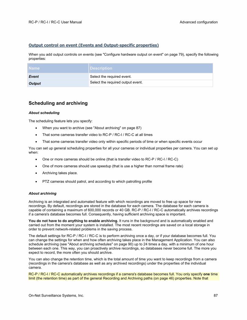
RC-P / RC-I / RC-C User Manual Advanced configuration
On-Net Surveillance Systems, Inc. 87
Output control on event (Events and Output-specific properties)
When you add output controls on events (see "Configure hardware output on event" on page 79), specify the following properties:
Name Description
Event Select the required event.
Output Select the required output event.
Scheduling and archiving
About scheduling
The scheduling feature lets you specify:
When you want to archive (see "About archiving" on page 87)
That some cameras transfer video to RC-P / RC-I / RC-C at all times
That some cameras transfer video only within specific periods of time or when specific events occur
You can set up general scheduling properties for all your cameras or individual properties per camera. You can set up when:
One or more cameras should be online (that is transfer video to RC-P / RC-I / RC-C)
One of more cameras should use speedup (that is use a higher than normal frame rate)
Archiving takes place.
PTZ cameras should patrol, and according to which patrolling profile
About archiving
Archiving is an integrated and automated feature with which recordings are moved to free up space for new recordings. By default, recordings are stored in the database for each camera. The database for each camera is capable of containing a maximum of 600,000 records or 40 GB. RC-P / RC-I / RC-C automatically archives recordings if a camera's database becomes full. Consequently, having sufficient archiving space is important.
You do not have to do anything to enable archiving. It runs in the background and is automatically enabled and carried out from the moment your system is installed. The most recent recordings are saved on a local storage in order to prevent network-related problems in the saving process.
The default settings for RC-P / RC-I / RC-C is to perform archiving once a day, or if your database becomes full. You can change the settings for when and how often archiving takes place in the Management Application. You can also schedule archiving (see "About archiving schedules" on page 90) up to 24 times a day, with a minimum of one hour between each one. This way, you can proactively archive recordings, so databases never become full. The more you expect to record, the more often you should archive.
You can also change the retention time, which is the total amount of time you want to keep recordings from a camera (recordings in the camera's database as well as any archived recordings) under the properties of the individual camera.
RC-P / RC-I / RC-C automatically archives recordings if a camera's database becomes full. You only specify one time limit (the retention time) as part of the general Recording and Archiving paths (on page 46) properties. Note that

Advanced configuration RC-P / RC-I / RC-C User Manual
88 On-Net Surveillance Systems, Inc.
retention time determines when archiving takes place. Retention time is the total amount of time for which you want to keep recordings from a camera (that is recordings in the camera's database as well as any archived recordings).
Backup of archives
OnSSI does recommend that you create backups based on the content of camera databases as it may cause sharing violations or other malfunctions. Instead, create backups based on the content of archives. If you have not specified separate archiving locations for separate cameras, you could back up the default local archiving directory, Archives.
Important: When you schedule a backup, make sure the backup job does not overlap with any scheduled archiving times.
If archiving fails
Under rare circumstances, archiving may fail, for example due to network problems. However, in RC-P / RC-I / RC-C this does not pose a threat. RC-P / RC-I / RC-C creates a new database and continues archiving in this new database. You can work with and view both this new database and the old one like any other databases.
About archiving locations
The default archiving folder (see "Default File Paths" on page 20) (C:\MediaDatabase) is located on the RC-P / RC-I / RC-C server. You can change the default archiving folder to any other location locally, or select a location on a network drive to use as the default archiving folder. In the archiving folder, separate subfolders for storing archives for each camera are automatically created. These subfolders are named after the MAC address of the hardware device to which the camera is connected.
Because you can keep archives spanning many days of recordings and archiving may take place several times per day, further subfolders, named with the archiving date and time, are also automatically created.
The subfolders are named according to the following structure:
...\Archives\CameraMACAddress_VideoEncoderChannel\DateAndTime
If the video encoder does not have several channels, the video encoder channel will always be _1 (example: 00408c51e181_1).
Example: an archiving at 23.15 on 31st December 2012 for a camera with the MAC address 00408c51e181 attached to channel 2 would be stored:
C:\MediaDatabase\Archives\00408c51e181_2\2012-12-31-23-15
ABOUT ARCHIVING TO OTHER LOCATIONS
When you archive to other locations than the default archiving directory, your system first temporarily stores the archive in the local default archiving directory, then immediately moves the archive to the archiving location you have specified. Archiving directly to a network drive can mean that archiving time varies depending on the available bandwidth on the network. First storing the archive locally, then moving it speeds up the archiving procedure, and reduces delays in case of network problems.
If you archive to a network drive, the regular camera database can only be stored on a local drive attached directly to your system's server. This is not supported with RC-P.
ABOUT DYNAMIC ARCHIVE PATHS
With dynamic archiving paths, you specify a number of different archiving paths, usually across several drives. OnSSI recommends using dynamic paths, which also is the default setting when you configure cameras through the Configure video & recording wizard (see "About video and recording configuration" on page 42).
If the path containing the camera's database is on one of the drives you have selected for dynamic archiving, your system always tries to archive to that drive first. If not, your system automatically archives to the archiving drive with the most available space at any time, provided a camera database is not using that drive.

RC-P / RC-I / RC-C User Manual Advanced configuration
On-Net Surveillance Systems, Inc. 89
The drive that has the most available space may change during the archiving process, and archiving may happen to several archiving drives during the same process. This does not have impact on how users find and view archived recordings.
Dynamic archiving paths are general for all your cameras. You cannot configure dynamic archiving paths for individual cameras.
When deciding which drives to use for dynamic archiving, consider the pros and cons in the following examples (in which we assume that the default archiving path (see "Default File Paths" on page 20) is on drive C:—drive letters are examples only, different drive letters may of course be used in your organization):
Camera records to drive C: and archives to drive C:
If the path containing the camera's database is on one of the drives you have selected for dynamic archiving, RC-P / RC-I / RC-C will always try to archive to that drive first. Archiving will take place quickly, but may also fill up the drive with data fairly quickly.
Camera records to drive C: and archives to drive D:
Recordings and archives are on separate drives. Archiving takes place less quickly. RC-P / RC-I / RC-C will first temporarily store the archive in the local default archiving directory on C:, then immediately move the archive to the archiving location on D:. Therefore, sufficient space to accommodate the temporary archive is required on C:.
Camera 1 records to drive C: and archives to drive D: while Camera 2 records to drive D: and archives to drive C:
Avoid this. One camera's archiving may take up space required for another camera's recordings. In the above example, Camera 1's archiving to D: may result in no recording space for camera 2 on D:. The rule is: "Do not cross recording and archiving drives."
If you use several surveillance servers in a master/slave setup, each surveillance server must archive to its own mapped location in order for archiving to work. If you attempt to archive to the same mapped location for all the servers, archiving will fail.
If you use several surveillance servers in a master/slave setup, each surveillance server must archive to its own mapped location in order for archiving to work. If you attempt to archive to the same mapped location for all the servers, archiving will fail.
About archiving audio
If you have enabled an audio source (for example, a microphone) on a hardware device, audio recordings are archived together with video recordings from the camera attached to the hardware device. If the hardware device is a video encoder with several channels, audio is archived with the camera on channel 1. When you have enabled an audio source, the system records audio to the associated camera’s database. This affects the database’s capacity for storing video. You may, therefore, want to use scheduled archiving more frequently if you record audio and video than if you only record video.
Storage capacity required for archiving
The storage capacity required for archiving depends entirely on the amount of recordings you plan to keep, and on how long you want to keep them (retention time). Some organizations want to keep archived recordings from a large number of cameras for several months or years. Other organizations may only want to archive recordings from one or two cameras, and they may want to keep their archives for much shorter periods of time.
You should always first consider the storage capacity of the local drive containing the default archiving directory to which archived recordings are always moved, even though they may immediately after be moved to an archiving location on another drive. Basically, the capacity of the local drive should be at least twice the size required for storing the databases of all cameras.

Advanced configuration RC-P / RC-I / RC-C User Manual
90 On-Net Surveillance Systems, Inc.
When you archive, RC-P / RC-I / RC-C automatically checks that space required for the data to be archived plus 1 GB of free disk space per camera is available at the archiving location. If not, the archive location's oldest data from the camera in question is deleted until there is sufficient free space for the new data to be archived.
When you estimate storage capacity required for archiving, consider your organization's needs, then plan for worst case rather than best case scenarios.
About archiving schedules
There are two ways in which to configure archiving schedules:
While you configure your cameras through the Configure Video and Recording wizard (see "Configure storage wizard" on page 26), in which case you configure your archiving schedule on the wizard's Drive selection page.
As part of the general Scheduling and Archiving properties: In the Management Application's navigation pane, expand Advanced Configuration, right-click Scheduling and Archiving, select Properties, select Archiving in the dialog, and specify relevant properties (see "Archiving" on page 94).
Automatic response if running out of disk space
If RC-P / RC-I / RC-C runs of disk space while archiving, you can set up an automatic response. Two scenarios can occur, depending on whether the camera database drive is different from, or identical to, the archiving drive:
Different drives: Automatic archiving if database drive runs out of disk space
In case the RC-P / RC-I / RC-C server is running out of disk space, and the archiving drive is different from the camera database drive, and archiving has not taken place within the last hour, archiving will automatically begin in an attempt to free up disk space. This will happen regardless of any archiving schedules. The server is considered to be running out of disk space if:
there is less than 10% disk space left, and the available disk space goes below 30 GB plus 1.5 GB per camera
the available disk space goes below 150 MB plus 20 MB per camera (example: with ten cameras, the server would be running out of disk space if the remaining available disk space went below 350 MB (150 MB plus 20 MB for each of the ten cameras))
The difference ensures that very large disks are not necessarily considered to be running out of disk space just because they have less than 10% disk space left.
On the archiving drive, RC-P / RC-I / RC-C automatically checks that the space required for data from a camera to be archived plus 1 GB of free disk space per camera is available. If not, the archive drive's oldest data from the relevant camera is deleted until there is sufficient free space for the new data to be archived.
IMPORTANT: You will lose the archive data that is deleted.
Same drive: Automatic moving or deletion of archives if drive runs out of disk space
Available functionality depends on your product version.
If your system server is running out of disk space, and the archiving drive is identical to the camera database drive, your system automatically does the following in an attempt to free up disk space:
1. First, the program will attempt to move archives (moving archives is only possible if you use dynamic archiving, with which you can archive to several different drives). This happens if:
o there is less than 15% disk space left, and the available disk space goes below 40 GB plus 2 GB per camera
- or -
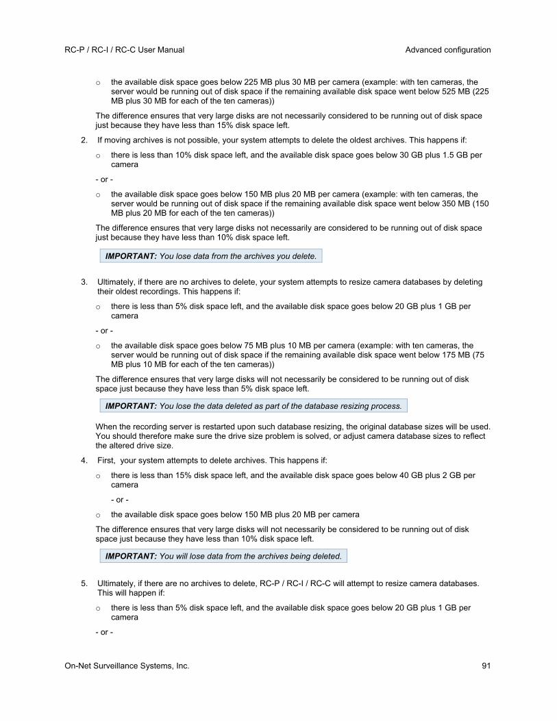
RC-P / RC-I / RC-C User Manual Advanced configuration
On-Net Surveillance Systems, Inc. 91
o the available disk space goes below 225 MB plus 30 MB per camera (example: with ten cameras, the server would be running out of disk space if the remaining available disk space went below 525 MB (225 MB plus 30 MB for each of the ten cameras))
The difference ensures that very large disks are not necessarily considered to be running out of disk space just because they have less than 15% disk space left.
2. If moving archives is not possible, your system attempts to delete the oldest archives. This happens if:
o there is less than 10% disk space left, and the available disk space goes below 30 GB plus 1.5 GB per camera
- or -
o the available disk space goes below 150 MB plus 20 MB per camera (example: with ten cameras, the server would be running out of disk space if the remaining available disk space went below 350 MB (150 MB plus 20 MB for each of the ten cameras))
The difference ensures that very large disks not necessarily are considered to be running out of disk space just because they have less than 10% disk space left.
3. Ultimately, if there are no archives to delete, your system attempts to resize camera databases by deleting their oldest recordings. This happens if:
o there is less than 5% disk space left, and the available disk space goes below 20 GB plus 1 GB per camera
- or -
o the available disk space goes below 75 MB plus 10 MB per camera (example: with ten cameras, the server would be running out of disk space if the remaining available disk space went below 175 MB (75 MB plus 10 MB for each of the ten cameras))
The difference ensures that very large disks will not necessarily be considered to be running out of disk space just because they have less than 5% disk space left.
When the recording server is restarted upon such database resizing, the original database sizes will be used. You should therefore make sure the drive size problem is solved, or adjust camera database sizes to reflect the altered drive size.
4. First, your system attempts to delete archives. This happens if:
o there is less than 15% disk space left, and the available disk space goes below 40 GB plus 2 GB per camera
- or -
o the available disk space goes below 150 MB plus 20 MB per camera
The difference ensures that very large disks will not necessarily be considered to be running out of disk space just because they have less than 10% disk space left.
5. Ultimately, if there are no archives to delete, RC-P / RC-I / RC-C will attempt to resize camera databases. This will happen if:
o there is less than 5% disk space left, and the available disk space goes below 20 GB plus 1 GB per camera
- or -
IMPORTANT: You lose data from the archives you delete.
IMPORTANT: You lose the data deleted as part of the database resizing process.
IMPORTANT: You will lose data from the archives being deleted.

Advanced configuration RC-P / RC-I / RC-C User Manual
92 On-Net Surveillance Systems, Inc.
o the available disk space goes below 75 MB plus 10 MB per camera (example: with ten cameras, the server would be running out of disk space if the remaining available disk space went below 175 MB (75 MB plus 10 MB for each of the ten cameras))
The difference ensures that very large disks will not necessarily be considered to be running out of disk space just because they have less than 5% disk space left.
When the recording server is restarted after database resizing, the original database sizes are used. Therefore, you should make sure that the drive size problem is solved, or adjust camera database sizes to reflect the altered drive size.
Tip: Should the database resizing procedure take place, you are informed on-screen in Ocularis Client, in log files, and or in notifications (see "About notifications" on page 100) (if set up).
View archived recordings
You can view archived recordings via the Ocularis Client. Use, for example, all of the Ocularis Client's advanced features (video browsing, and export) for archived recordings.
Stored archives
Exported archives
Configure general scheduling and archiving
To configure general scheduling and archiving, do the following:
1. In the Management Application navigation pane, expand Advanced Configuration, right-click Scheduling and Archiving, and select Properties.
2. Specify properties as required for Scheduling all cameras (on page 92), Scheduling options (on page 94), and Archiving (on page 94).
3. Your system comes with two simple schedule profiles, Always on and Always off, which you cannot edit or delete. If these do not meet your needs, you can create any number of customized schedule profiles for each camera. You can reuse a customized schedule profile for more than one purpose if you want to.
4. Save your configuration changes by clicking Save in the yellow notification bar in the upper-right corner of the Management Application.
General scheduling properties
Scheduling all cameras
When you configure general scheduling and archiving (see "Configure general scheduling and archiving" on page 92), you can specify certain properties for many cameras in one go. Do this to speed up things, or because the properties in question are shared by all cameras rather than being specific to individual cameras.
Note that you can specify the properties for Online Period, Speedup, Notifications (Email and SMS), and PTZ Patrolling individually for each camera.
Properties available for RC-P, RC-I and RC-C:
IMPORTANT: You lose the data deleted as part of the database resizing process.
When archiving, disable any virus scanning (on page 8) of camera databases and archiving locations.

RC-P / RC-I / RC-C User Manual Advanced configuration
On-Net Surveillance Systems, Inc. 93
Name Description
Template
The template can help you configure similar properties quickly. Say you have 20 cameras and you want to change the recording path, archiving path, and retention time for all of them. Instead of having to enter the same three pieces of information 20 times, you can simply enter them once in the template, and then apply the template to the 20 cameras with only two clicks.
Apply Template Select which cameras you want to apply the template for. Use one of the two Set buttons to actually apply the template.
Camera
The name as it appears in the Management Application, the Ocularis Administrator, and Ocularis Clients (standard, Mobile and Web). You may, however, assign an additional camera name in Ocularis that will not affect the name stored here.
Online
Select the required profile (for example Always on) for the online schedule (see "Configure camera-specific schedules" on page 44) for the relevant camera(s).
You specify a camera's online periods by creating schedule profiles based on:
Periods of time (example: Mondays from 08.30 until 17.45), displayed in pink.
Events within periods of time (example: from Event A occurs until Event B occurs Mondays from 08.30 until 17.45), displayed in yellow.
The two options can be combined, but they cannot overlap in time.
Select the required profile for the e-mail notification schedule for the camera(s) in question. You specify a camera's e-mail notification periods by creating schedule profiles based on periods of time (example: Mondays from 08.30 until 17.45), displayed in blue.
Select All Click button to select all cameras in the Apply Template column.
Clear All Click button to clear all selections in the Apply Template column.
Set selected template value on selected cameras
Apply only a selected value from the template to selected cameras.
Tip: To select more than one value press CTRL while selecting.
New schedule profile Create a new schedule profile of any type by clicking the Create... button.
Properties available in RC-C and RC-I only:
SMS
Select the required profile for the SMS notification schedule for the camera(s) in question. You specify a camera's SMS notification periods by creating schedule profiles based on periods of time (example: Mondays from 08.30 until 17.45), displayed in green.
PTZ Patrolling
Only available for PTZ (pan-tilt-zoom) cameras with patrolling, the continuous movement of a PTZ camera between a number of preset positions. Lets you select the required profile for the PTZ patrolling schedule (see "PTZ patrolling" on page 96) for the camera(s) in question.
You specify a camera's patrolling schedule based on patrolling profiles within particular periods of time (example: Mondays from 08.30 until 17.45), displayed in red.

Advanced configuration RC-P / RC-I / RC-C User Manual
94 On-Net Surveillance Systems, Inc.
Scheduling options
When you configure general scheduling and archiving (see "Configure general scheduling and archiving" on page 92), you can specify certain properties for many cameras in one go. In the case of Scheduling Options, it is because the properties are shared by all cameras.
Name Description
Start cameras on client requests
Cameras may be offline, for example because they have reached the end of an online recording schedule (see "Online period" on page 95), in which case client users will not be able to view live video from the cameras. However, if you select Start cameras on client requests, client users will be able to view live video from the camera outside online schedule—but without recording (technically: force the camera to be online outside its online schedule).
You must select Enable recording when started on client request (see the following), if you want recording to take place.
Enable recording when started on client request
Enable recording on the camera when Start cameras on client requests (see the previous) is also selected.
If a user does not have access to manual recording (see "Camera access" on page 113), selecting Enable recording when started on client request, will not enable the user to do manual recording.
Schedule profile for new cameras
Select which online schedule profile to use as default for cameras you subsequently add to your RC-P / RC-I / RC-C system. Note that your selection only applies for the online schedule, not for any other schedules. Default selection is Always on, meaning that new cameras will always be online, that is transferring video to the RC-P / RC-I / RC-C server for live viewing and further processing.
Maximum delay between reconnect attempts
Control the aggressiveness of reconnection attempts. If RC-P / RC-I / RC-C loses the connection to a camera, it will by default attempt to re-establish the connection after ten seconds. In some environments, for example if using vehicle-mounted cameras through wireless connections, camera connections may frequently be lost, and you may want to change the aggressiveness of such reconnection attempts.
You can view live and even record video from a camera outside its online recording schedule. To do this, you select the Start cameras on client requests and, if needed, the Enable recording when started on client request options in the following when setting up your scheduling properties for the camera in question.
Archiving
RC-P / RC-I / RC-C automatically archives (see "About archiving" on page 87) recordings if a camera's database becomes full (in earlier versions, this was an option configured individually for each camera).
Properties available in RC-P, RC-I and RC-C:
Name Description
Archiving Times
Specify when you want RC-P / RC-I / RC-C to automatically move recordings to your archiving path(s). You can specify up to 24 archiving times per day, with minimum one hour between each one. Select the hour, minute and second values and click the up and down buttons to increase or decrease values, or simply overwrite the selected value, and then click Add. The more you expect to record, the more often you should archive.

RC-P / RC-I / RC-C User Manual Advanced configuration
On-Net Surveillance Systems, Inc. 95
Name Description
Send e-mail on archiving failure
If selected, RC-P / RC-I / RC-C will automatically send an e-mail to selected recipients if archiving fails. This requires that the e-mail notification feature is enabled. Recipients are defined as part of the e-mail notification properties (see "Email (Properties)" on page 101).
Properties available in RC-C and RC-I only:
Send SMS on archiving failure
If selected, RC-P / RC-I / RC-C will automatically send an SMS (mobile phone text message) to selected recipients if archiving fails. This requires that the SMS notification feature is enabled. Recipients are defined as part of the SMS notification properties (see "SMS properties" on page 103).
Properties available in RC-C only:
Archive on event If selected, RC-P / RC-I / RC-C starts archiving when a certain event occurs. Select the event from the list.
Camera-specific scheduling properties
Online period
When you configure scheduling (see "Configure camera-specific schedules" on page 44) for specific cameras, your Online Period settings are probably the most important, since they determine when each camera should transfer video to RC-P / RC-I / RC-C.
By default, cameras added to RC-P / RC-I / RC-C are automatically online, and you only need to modify the online period settings if you require cameras to be online only at specific times or events. Note, however, that this default may be changed as part of the general scheduling options (see "Scheduling options" on page 94), in which case cameras added at a later time are not automatically online.
The fact that a camera transfers video to RC-P / RC-I / RC-C does not necessarily mean that video from the camera is recorded. Recording is configured separately, see Configure video and recording (see "About video and recording configuration" on page 42).
Name Description
Online
Select the required profile (for example Always on) for the online schedule (see "Configure camera-specific schedules" on page 44) for the relevant camera(s).
You specify a camera's online periods by creating schedule profiles based on:
Periods of time (example: Mondays from 08.30 until 17.45), displayed in pink.
Events within periods of time (example: from Event A occurs until Event B occurs Mondays from 08.30 until 17.45), displayed in yellow.
The two options can be combined, but they cannot overlap in time.
Tip: If you want to view live video as well as record video from a camera outside its online recording schedule, you can select the Start cameras on client requests (see "Scheduling options" on page 94) and, if needed, the Enable

Advanced configuration RC-P / RC-I / RC-C User Manual
96 On-Net Surveillance Systems, Inc.
recording when started on client request (see "Scheduling options" on page 94) options to set up your scheduling properties for a relevant camera.
Speedup
Speedup may also take place based on events, but that is configured elsewhere. See Frame rate - MJPEG (General recording and storage properties) (see "Frame rate - MJPEG" on page 54) and Video (Camera-specific properties) (see "Video" on page 61).
Name Description
Speedup
For specific MJPEG cameras, specify speedup periods. Before you can define this type of schedule, you must enable (see "Frame rate - MJPEG" on page 54) speedup. You specify a camera's speedup periods by creating schedule profiles based on periods of time (example: Mondays from 08.30 until 17.45), displayed in olive green.
PTZ patrolling
When you configure scheduling (see "Configure camera-specific schedules" on page 44) for PTZ (pan-tilt-zoom) cameras capable of patrolling (see "PTZ patrolling" on page 71), you can specify which patrolling profiles to use at specific times. Before you can define this type of schedule, you must configure patrolling for the relevant cameras.
Name Description
PTZ Patrolling
Only available for PTZ (pan-tilt-zoom) cameras with patrolling, the continuous movement of a PTZ camera between a number of preset positions. Lets you select the required profile for the PTZ patrolling schedule (see "PTZ patrolling" on page 96) for the camera(s) in question.
You specify a camera's patrolling schedule based on patrolling profiles within particular periods of time (example: Mondays from 08.30 until 17.45), displayed in red.
Use of one patrolling profile may be followed immediately by use of another (example: use the Daytime patrolling profile Mondays from 08.30 until 17.45, then the Evening patrolling profile Mondays from 17.45 until 23.00). Use of two patrolling profiles cannot overlap.
Unlike other types of scheduling, there are no ready-made Always on and Always off schedule profiles for PTZ patrolling. You can create any number of customized schedule profiles for each camera. When you create a customized schedule profile (see "Configure camera-specific schedules" on page 44) for one camera, you can reuse it with other cameras if required.
NetMatrix
About NetMatrix video sharing
NetMatrix allows distributed viewing of live video from any camera to any NetMatrix-recipient on a network operating with RC-P / RC-I / RC-C. A computer on which NetMatrix-triggered video can be viewed is known as a NetMatrix recipient. In order to become a NetMatrix recipient, the computer must have the Ocularis Client installed.
NetMatrix is used solely with Ocularis Client in Limited Mode. If you are using Ocularis Client in standard mode, NetMatrix is not necessary. Documentation is included here only for those customers who use it.
There are two ways in which NetMatrix-triggered video can appear on a NetMatrix-recipient:
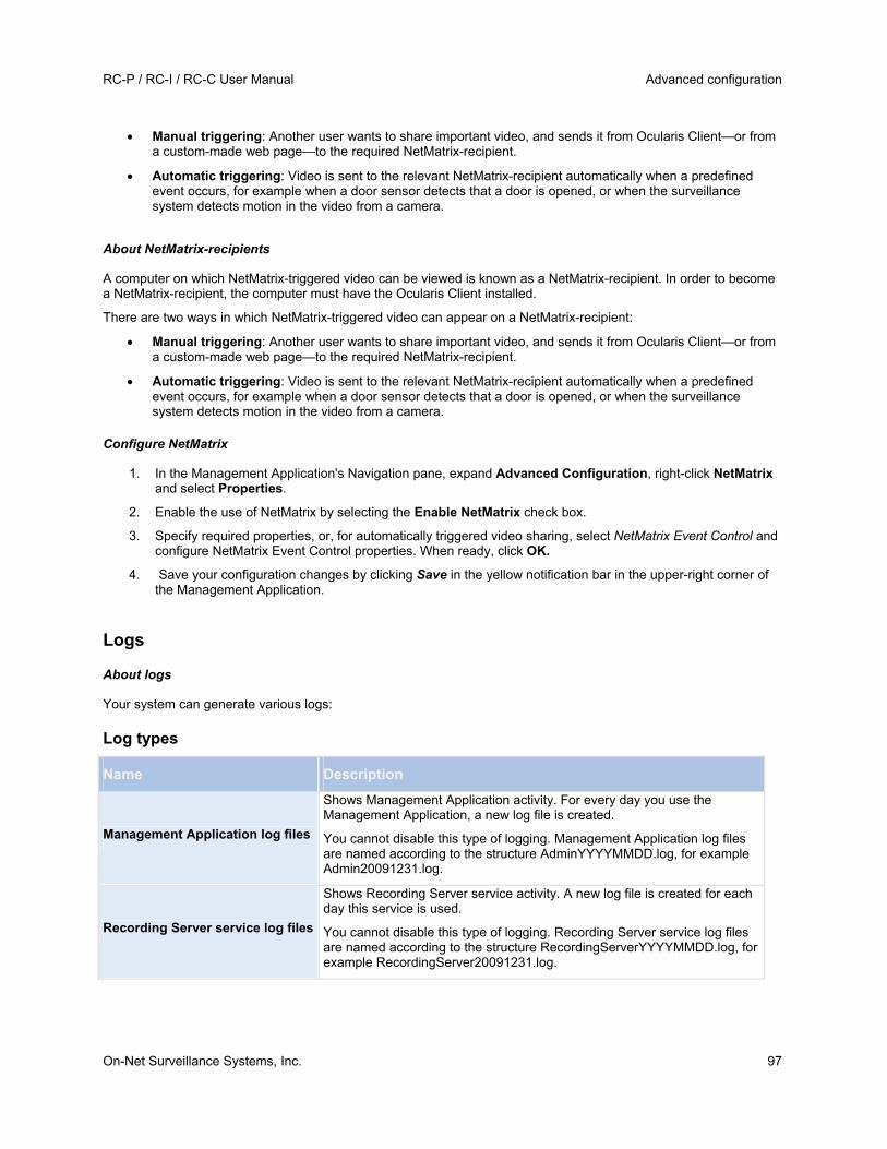
RC-P / RC-I / RC-C User Manual Advanced configuration
On-Net Surveillance Systems, Inc. 97
Manual triggering: Another user wants to share important video, and sends it from Ocularis Client—or from a custom-made web page—to the required NetMatrix-recipient.
Automatic triggering: Video is sent to the relevant NetMatrix-recipient automatically when a predefined event occurs, for example when a door sensor detects that a door is opened, or when the surveillance system detects motion in the video from a camera.
About NetMatrix-recipients
A computer on which NetMatrix-triggered video can be viewed is known as a NetMatrix-recipient. In order to become a NetMatrix-recipient, the computer must have the Ocularis Client installed.
There are two ways in which NetMatrix-triggered video can appear on a NetMatrix-recipient:
Manual triggering: Another user wants to share important video, and sends it from Ocularis Client—or from a custom-made web page—to the required NetMatrix-recipient.
Automatic triggering: Video is sent to the relevant NetMatrix-recipient automatically when a predefined event occurs, for example when a door sensor detects that a door is opened, or when the surveillance system detects motion in the video from a camera.
Configure NetMatrix
1. In the Management Application's Navigation pane, expand Advanced Configuration, right-click NetMatrix and select Properties.
2. Enable the use of NetMatrix by selecting the Enable NetMatrix check box.
3. Specify required properties, or, for automatically triggered video sharing, select NetMatrix Event Control and configure NetMatrix Event Control properties. When ready, click OK.
4. Save your configuration changes by clicking Save in the yellow notification bar in the upper-right corner of the Management Application.
Logs
About logs
Your system can generate various logs:
Log types
Name Description
Management Application log files
Shows Management Application activity. For every day you use the Management Application, a new log file is created.
You cannot disable this type of logging. Management Application log files are named according to the structure AdminYYYYMMDD.log, for example Admin20091231.log.
Recording Server service log files
Shows Recording Server service activity. A new log file is created for each day this service is used.
You cannot disable this type of logging. Recording Server service log files are named according to the structure RecordingServerYYYYMMDD.log, for example RecordingServer20091231.log.

Advanced configuration RC-P / RC-I / RC-C User Manual
98 On-Net Surveillance Systems, Inc.
Name Description
Image Server service log files
Shows Image Server service activity. A new log file is created for each day the service is used.
You cannot disable this type of logging. Image Server service log files are named according to the structure ISLog_YYYYMMDD.log, for example ISLog_20091231.log.
Image Import service log files
Shows Image Import service activity, when this service is used for fetching pre-alarm images, and storing the fetched images in camera databases.
Pre-alarm images is a feature available for selected cameras only. It enables sending of images from immediately before an event took place from the camera to the surveillance system via e-mail. A new log file is created for each day the service is used.
You cannot disable this type of logging. Image Import service log files are named according to the structure ImageImportLog_YYYMMDD.log, for example ImageImportLog20091231.log.
Audit log files
Shows Ocularis Client user activity (if audit logging is enabled).
A new log file is created for each day with audit logging enabled and client user activity. Audit log files are named according to the structure is_auditYYYMMDD.log, for example is_audit20091231.log. The _is prefix is due to the fact that the audit log files are generated by the Image Server service.
Log locations
All log files are by default placed in the appropriate All Users folder for the operating system you are using. By default, they are stored there for seven days. Note that you can change log file locations as well as the number of days to store the logs when you configure logging.
Log structures
Most log files generated by your system use a shared structure complying with the W3C Extended Log File Format. Each log file consists of a header and a number of log lines:
The header outlines the information contained in the log lines.
The log lines consist of two main parts: the log information itself as well as an encrypted part. The encrypted part makes it possible, through decryption and comparison, to assert that a log file has not been tampered with.
Log integrity checks
All log files, except Management Application log files, are subjected to an integrity check once every 24 hours. The integrity check is performed by your system's Log Check service. The result of the integrity check is automatically written to a file named according to the structure LogCheck_YYYYMMDD.log, for example LogCheck_20091231.log. Like the log files themselves, the log check files are by default placed in the appropriate All Users folder for the operating system you are using.
Any inconsistencies are reported in the form of error messages written in the log check file. Possible error messages:
Name Description
Log integrity information was not found. Log integrity can't be guaranteed.
The log file could not be checked for integrity.

RC-P / RC-I / RC-C User Manual Advanced configuration
On-Net Surveillance Systems, Inc. 99
Name Description
Log information does not match integrity information. Log integrity can't be guaranteed.
The log file exists, but does not contain the expected information. Log integrity cannot be guaranteed.
[Log file name] not found The log file was not present.
[Log file name] is empty The log file was present, but empty.
Last line changed/removed in [log file name]
The last line of the log file did not match the validation criteria.
Encrypted data missing in [log file name] near line [#]
The encrypted part of the relevant log line was not present.
Inconsistency found in [log file name] near line [#]
The log line does not match the encrypted part.
Inconsistency found in [log file name] at beginning of log file
The log file header is not correct. This situation is most likely to occur if a user has attempted to delete the beginning of a log file.
Note: Other messages that are not error-related may also appear in the log check file.
Configure system, event and audit logging
RC-P / RC-I / RC-C can generate various logs.
To configure logging, do the following:
1. In the Management Application's Navigation pane, expand Advanced Configuration, right-click Logs and select Properties.
2. Specify properties (see "Log properties" on page 99) for your system logs, including the event log and the audit log. Administrators can only disable/enable audit logging. All other logs are compulsory.
3. Save your configuration changes by clicking Save in the yellow notification bar in the upper-right corner of the Management Application.
Log properties
RC-P / RC-I / RC-C can generate various types of logs. When you configure logs, you can define the following:
Logs (Management Application log, Recording Server service log, Image Server service log, and Image Import service log)
Name Description
Path
These log files are by default placed in the appropriate All Users folder for the operating system you are using.
To specify another location for your log files, type the path to the required folder in the Path field, or click the browse button next to the field to browse to the required folder.

Advanced configuration RC-P / RC-I / RC-C User Manual
100 On-Net Surveillance Systems, Inc.
Name Description
Days to log
A new log file is created each day the Management Application and/or the services are used. A log file older than the number of days specified in the field is automatically deleted. By default, the log file will be stored for seven days. To specify another number of days (max. 9999), simply overwrite the value in the field. The current day's activity is always logged, even with a value of 0 in the field. Therefore, if you specify 0, you will log current day's activity; if you specify 1, you will keep one day plus the current day's activity, and so on.
Audit Log
Name Description
Enable audit logging Audit logging is the only type of RC-P / RC-I / RC-C logging which is not compulsory. Select/clear the check box to enable/disable audit logging.
Path
These log files are by default placed in the appropriate All Users folder for the operating system you are using.
To specify another location for your log files, type the path to the required folder in the Path field, or click the browse button next to the field to browse to the required folder.
Days to log
A new log file is created for each day with audit logging enabled and client user activity. A log file older than the number of days specified in the field is automatically deleted. By default, the log file is stored for seven days. To specify another number of days (max. 9999), overwrite the value in the field. The current day's activity is always logged (provided audit logging is enabled and there is user activity). Therefore, if you specify 1, you keep one day plus the current day's activity. Note that if you specify 0 (zero), audit log files are kept indefinitely (disk space permitting).
Minimum logging interval Minimum number of seconds between logged events. Specifying a high number of seconds between logged events may help reduce the size of the audit log. Default is 60 seconds.
In sequence timespan
The number of seconds to pass for viewed images to be considered to be within the same sequence. Specifying a high number of seconds may help limit the number of viewed sequences logged and reduce the size of the audit log. The default is ten seconds.
Notifications
About notifications
In case of problems with hardware, activation of motion detection on your camera or similar incidents, you can set up your system to send notifications through SMS and/or email.
Notifications are set up typically in the Ocularis Administrator for Ocularis Base. However, some methods of alerting may be configured at the recorder level and discussed here.
About email
With email notifications, you can instantly get notified when your surveillance system requires attention. RC-P / RC-I / RC-C can automatically send e-mail notifications to one or more recipients when:

RC-P / RC-I / RC-C User Manual Advanced configuration
On-Net Surveillance Systems, Inc. 101
Motion (see "Motion detection & exclude regions" on page 68) is detected
Events occur. You can select individually for each event whether you want to receive an email notification or not.
Archiving (see "About archiving" on page 87) fails (if email notification has been selected as part of the archiving properties (see "Archiving" on page 94))
Configure email notifications
To set up email notifications, do the following:
In the Management Application's Navigation pane, expand Advanced Configuration, expand Notifications, right-click Email and select Properties.
1. Enable the use of email by selecting the Enable email check box.
2. Specify required properties (see "Message Settings (email)" on page 101).
3. Choose a schedule profile to associate with your email notifications. Your system comes with two simple schedule profiles, Always on and Always off, which you cannot edit or delete. If these do not meet your needs, you can create any number of customized schedule profiles for each camera. You can reuse a customized schedule profile for more than one purpose if you want to.
Email (Properties)
MESSAGE SETTINGS (EMAIL)
Specify the following message settings for email:
Name Description
Enable Select to enable the use of email notifications, allowing you to specify further properties.
Recipient(s) Specify the email addresses to which the system should send email notifications. To specify more than one e-mail address, separate the e-mail addresses with semicolons (example: [email protected]; [email protected]; [email protected]).
Subject text Enter a subject text for email notifications.
Message text Enter a message text for email notifications. Note that camera information as well as date and time information is automatically included in email notifications.
Variables
Click a link to include a variable to the notification. The options are:
Name of triggering event
Camera name
Trigger time (the time when the notification was registered)
Error text (for example, camera failure)
Ignore similar messages for:
Specify the number of seconds to ignore sending similar notifications. This function is to ensure that you do not receive too many notifications before you have solved the relevant problem.
Use schedule profile
Select the schedule profile you want to use. By default, you can choose between Always On, Always Off or choose Add new... to set up a custom schedule (see "Notification Scheduling properties" on page 105).

Advanced configuration RC-P / RC-I / RC-C User Manual
102 On-Net Surveillance Systems, Inc.
ATTACHMENT SETTINGS (EMAIL)
Specify the following attachment settings:
Component Requirement
Include images
Select the check box to include still images in email notifications. When selected, each email notification includes one or more attached still JPEG images.
Attached images includes images of before the incident, after the incident and the actual incident, with the incident that triggered the notification in the middle.
Important: If your device does not record any images while the sending of notifications are turned on, no images are included in the email notification you receive.
Number of images The number of images you want to include in the email. You can include between 1 and 20 images.
Time between images (ms) Minimum time (in milliseconds) to be between each image. You can set any time range between 0 and 300 seconds (5 minutes).
Embed images in email Select the check box to embed images directly in the email.
SERVER SETTINGS (EMAIL)
Specify the following server settings for email:
Component Requirement
Sender e-mail address Enter the email address you wish to use as the sender of the email notification.
Outgoing mail server address (SMTP)
Type the name of the SMTP (Simple Mail Transfer Protocol) server which you want to use to send the email notifications.
Compared with other mail transfer methods, SMTP has the advantage that you avoid automatically triggered warnings from your email client. Such warnings may otherwise inform you that your email client is trying to automatically send email messages on your behalf.
TLS (Transport Layer Security) and its predecessor, SSL (Secure Socket Layer), are supported.
Outgoing mail server port (SMTP) Type the port for your mail server. The default port number is 25.
Server requires login Select the check box if you must use a user name and password to use the SMTP server.
Security type Choose the type of security you want to use.
User name Only relevant when you have selected Server requires login. Specify the user name required for using the SMTP server.
Password Only relevant if you have selected Server requires login. Specify the password required for using the SMTP server.

RC-P / RC-I / RC-C User Manual Advanced configuration
On-Net Surveillance Systems, Inc. 103
Component Requirement
Max attachment size (MB) Specify a maximum size of attached images.
SMS
About SMS
With SMS notifications, you can instantly get notified on your mobile device when your surveillance system requires attention. To use the SMS notification feature, you must connect a 3G/USB modem to the server on which you have installed your system.
Your system can automatically send SMS notifications when:
Motion (see "Motion detection & exclude regions" on page 68) is detected
Events occur. You can select individually for each event whether you want to receive an SMS notification or not.
Archiving (see "About archiving" on page 87) fails (if an SMS notification has been selected as part of the archiving properties (see "Archiving" on page 94)).
Configure SMS notifications
To configure SMS notifications, do the following:
1. In the Management Application's Navigation pane, expand Advanced Configuration, expand Notifications, right-click SMS and select Properties.
2. Enable the use of SMS by selecting the Enable SMS check box.
3. Specify required properties (see "SMS properties" on page 103).
4. Choose a schedule profile to associate with your SMS notifications.
Note: Your system comes with two simple schedule profiles, Always on and Always off, which you cannot edit or delete. If these do not meet your needs, you can create any number of customized schedule profiles for each camera. You can reuse a customized schedule profile for more than one purpose if you want to.
SMS properties
MESSAGE SETTINGS (SMS)
Specify the following message settings for SMS:
Component Requirement
Enable SMS Enables the use of SMS notifications, allowing you to specify further properties.
Recipient(s) Indicate the telephone number of the recipient. To send SMS to more than one recipient, separate the phone numbers with a semicolon.
Message text
Specify required message text for the SMS notification. Message text must only contain the following characters: a-z, A-Z, 0-9 as well as commas (,) and full stops (.). Note that camera information, date and time information are all automatically included in SMS notifications.

Advanced configuration RC-P / RC-I / RC-C User Manual
104 On-Net Surveillance Systems, Inc.
Component Requirement
Variables
Click a link to include a variable to the notification. The options are:
Name of triggering event
Camera name
Trigger time (the time when the notification was registered)
Error text (for example, camera failure)
Ignore similar messages for:
Specify the number of seconds to ignore sending similar notifications. This function is to ensure that you do not receive too many notifications before you have solved the relevant problem.
Use schedule profile
Select the schedule profile you want to use. By default, you can choose between Always On, Always Off or choose Add new... to set up a custom schedule (see "Notification Scheduling properties" on page 105).
SERVER SETTINGS (SMS)
Specify the following server settings for SMS:
Component Requirement
Serial port
Select the serial port to use for your USB/3G modem. The list from which you can choose ports shows open serial ports on the computer running your system.
Speed
The baud speed of your USB modem device. The default value is 9600 baud. Although you can set any custom value for the baud rate, OnSSI does not recommend that you change the baud rate unless you are a highly advanced user.
SIM card PIN code Specify PIN code for the SIM card inserted in the USB/3G modem.
SMS encoding
Different types of SMS encodings exist to accommodate various language needs in the world. RC-P / RC-I / RC-C gives you the following options:
7-bit
8-bit (default)
16-bit
7-bit encryption allows you to use up to 160 characters per SMS, however it also limits the type of characters you can use.
8-bit encryption is the standard form of encryption with more special characters allowed. It allows you to use up to 140 characters per SMS.
16-bit encryption is necessary for non-Latin alphabet languages. Characters from, for example, Arabic, Chinese, Korean, Japanese or Cyrillic alphabet languages require 16-bit SMS encoding. If you use any of these languages in your organization, you must set your RC-P / RC-I / RC-C to use 16-bit encoding. 16-bit has a limit of 70 characters per SMS.

RC-P / RC-I / RC-C User Manual Advanced configuration
On-Net Surveillance Systems, Inc. 105
Scheduling
About scheduling of notifications
Scheduling of notifications allows you to set up schedule profiles which you can use with Email (see "Message Settings (email)" on page 101) and SMS (see "Message Settings (SMS)" on page 103) notifications.
Notification Scheduling properties
When you set up schedules to use with email or SMS notifications, specify the following:
Component Requirement
Notification profile
Select the relevant profile (for example Always on) for your notification schedule profile.
You specify a notification schedule profile by creating schedule profiles based on:
Periods of time (example: Mondays from 08.30 until 17.45), shown in blue:
NetCentral
About NetCentral
NetCentral Settings lets you specify the login settings required for a NetCentral server to access the surveillance system in order to retrieve status information and alerts. NetCentral works in conjunction with a recorder's event proxy (RC-I and RC-C) to forward events from the recorder to the event proxy. The event proxy forwards the events to the recorder or other configured server.
Enable NetCentral
1. In the Management Application's Navigation pane, expand Advanced Configuration, right-click NetCentral and then select Properties.
2. Enable the use of NetCentral connections by selecting the Enable OnSSI NetCentral check box.
3. Specify required properties (see "NetCentral properties" on page 105).
4. Save your configuration changes by clicking Save in the yellow notification bar in the upper-right corner of the Management Application.
NetCentral properties
Name Description
Enable OnSSI NetCentral connections
Enables the use of NetCentral connections, allowing you to specify further properties.
Login Name Type the name used for the connection between NetCentral and the event proxy. The name here must match the name specified on the event proxy.
Password Type the password used for the account listed in the Login name field above. This password must match the one configured in the event proxy.

Advanced configuration RC-P / RC-I / RC-C User Manual
106 On-Net Surveillance Systems, Inc.
Name Description
Port Type the port number to which NetCentral should connect when accessing the event proxy. The port numbers must match here and on the configured proxy. Default port is 1237.
NetCentral is support on RC-I and RC-C.
Server access
About server access
You can configure clients' access to your system's server in two ways:
Wizard-driven: Guided configuration which lets you specify how clients access the server and which users can use clients. See Configure User Access wizard (see "Manage user access wizard" on page 34). When you use the wizard, all users that you add have access to all cameras, including new cameras added at a later stage. If this is not what you want, specify access settings, users and user rights separately.
Through advanced configuration: In previous versions of RC-P / RC-I / RC-C, this was known as Image Server administration, since technically it is the Image Server service (see "About services" on page 115) which handles clients' access to the surveillance system.
About registered services
Registered services displays the services installed and running on your RC-P / RC-I / RC-C system. It displays the following information about the individual services:
Name Description
Enabled Indicates if the relevant service is enabled.
Name The name of the service.
Description A description of the service.
Addresses The inside and outside addresses used by the service.
You can change the inside and outside addresses for a service. To do this, click the Edit button and enter the relevant inside and/or outside addresses. Note that you cannot edit all services. You can delete a service registration from the system by clicking the Delete button. You are prompted for confirmation before the service is deleted.
Configure server access
1. In the Management Application's navigation pane, expand Advanced Configuration, right-click Server Access and select Properties.
2. Specify required properties for Server Access (on page 107), Local IP Ranges (on page 108), and Language Support and XML Encoding. Your system comes with two simple schedule profiles, Always on and Always off, which you cannot edit or delete. If these do not meet your needs, you can create any number of customized schedule profiles for each camera. You can reuse a customized schedule profile for more than one purpose if you want to.
3. Save your configuration changes by clicking Save in the yellow notification bar in the upper-right corner of the Management Application.
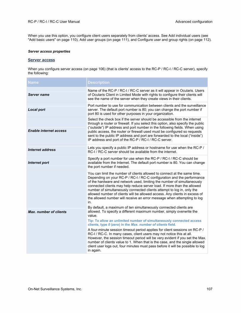
RC-P / RC-I / RC-C User Manual Advanced configuration
On-Net Surveillance Systems, Inc. 107
When you use this option, you configure client users separately from clients' access. See Add individual users (see "Add basic users" on page 110), Add user groups (on page 111), and Configure user and group rights (on page 112).
Server access properties
Server access
When you configure server access (on page 106) (that is clients' access to the RC-P / RC-I / RC-C server), specify the following:
Name Description
Server name Name of the RC-P / RC-I / RC-C server as it will appear in Ocularis. Users of Ocularis Client in Limited Mode with rights to configure their clients will see the name of the server when they create views in their clients.
Local port Port number to use for communication between clients and the surveillance server. The default port number is 80; you can change the port number if port 80 is used for other purposes in your organization.
Enable internet access
Select the check box if the server should be accessible from the internet through a router or firewall. If you select this option, also specify the public (“outside”) IP address and port number in the following fields. When using public access, the router or firewall used must be configured so requests sent to the public IP address and port are forwarded to the local (“inside”) IP address and port of the RC-P / RC-I / RC-C server.
Internet address Lets you specify a public IP address or hostname for use when the RC-P / RC-I / RC-C server should be available from the internet.
Internet port Specify a port number for use when the RC-P / RC-I / RC-C should be available from the Internet. The default port number is 80. You can change the port number if needed.
Max. number of clients
You can limit the number of clients allowed to connect at the same time. Depending on your RC-P / RC-I / RC-C configuration and the performance of the hardware and network used, limiting the number of simultaneously connected clients may help reduce server load. If more than the allowed number of simultaneously connected clients attempt to log in, only the allowed number of clients will be allowed access. Any clients in excess of the allowed number will receive an error message when attempting to log in.
By default, a maximum of ten simultaneously connected clients are allowed. To specify a different maximum number, simply overwrite the value.
Tip: To allow an unlimited number of simultaneously connected access clients, type 0 (zero) in the Max. number of clients field.
A four-minute session timeout period applies for client sessions on RC-P / RC-I / RC-C. In many cases, client users may not notice this at all. However, the session timeout period will be very evident if you set the Max. number of clients value to 1. When that is the case, and the single allowed client user logs out, four minutes must pass before it will be possible to log in again.
Advanced configuration RC-P / RC-I / RC-C User Manual
108 On-Net Surveillance Systems, Inc.
Local IP ranges
You can specify IP address ranges which RC-P / RC-I / RC-C should recognize as coming from a local network. This can be relevant if different subnets are used across your local network.
1. Click the Add button.
2. In the Start Address column, specify the first IP address in the range.
3. In the End Address column, specify the last IP address in the range.
4. Repeat if you want to add other local IP address ranges.
Tip: If required, an IP address range can include only one IP address (example: 192.168.10.1-192.168.10.1).
Master/Slave
About master and slave
You can create a master/slave setup of your system servers. A master/slave setup allows remote users to transparently connect to more than one server at the same time. When remote users connect to the master server, they instantly get access to the slave servers as well.
You can designate an unlimited number of servers per SLC (Software License Code) as master servers. If you need to, for example if your organization is very large and spread over many geographical locations, or in case your organization wants to create a redundancy solution, you can use several master servers in a master/slave setup. You can use up to four servers as slave servers under a designated master server that uses the same SLC.
Master/Slave setup is not necessary when using Ocularis. The documentation is included here for legacy installations.
Configure master and slave servers
Configure a master/slave setup
In the Management Application 's Navigation pane, expand Advanced Configuration, right-click Master/Slave and select Properties.
1. Select the Enable as master server check box.
2. Click Add to add a slave server.
3. Specify slave server properties. When ready, click OK.
4. Save your configuration changes by clicking Save in the yellow notification bar in the upper-right corner of the Management Application.
Add a slave server
To add a slave server, expand Advanced Configuration in the Management Application, right-click Master/Slave and select Add New Slave Server, then specify slave server properties. You can also add slave servers from the Master/Slave Properties window by clicking Add.
Tip: Instead of specifying a host name when adding a slave server, you can specify the IP address of the slave server. Type in the IP address in the Address field when you add the slave server. Remember you must use the local IP address of the slave server if you are on a local network.
Before you start using your master/slave setup, remember to verify that:
Required users have be defined on the master server as well as on each of the slave servers.
Public Access (see "Configure server access" on page 106) has been enabled on all involved servers, and ports mapped accordingly in the routers or firewalls used, if the slave servers are to be accessed from the internet.

RC-P / RC-I / RC-C User Manual Advanced configuration
On-Net Surveillance Systems, Inc. 109
When you use a master/slave setup, remote users and their rights must be defined in the Management Application's Users section on the master server as well as on each of the slave servers. Only cameras to which a remote user has been given access will be visible to the user, regardless of whether the cameras are connected to the master server or to one of the slave servers. If they are to be accessed from the internet, you must enable Public Access on all involved servers, and map ports accordingly in the routers and/or firewalls used.
Frequently asked questions about using master/slave
How many master servers can I use in a master/slave setup?
You can designate an unlimited number of servers per SLC (Software License Code, specified during installation) as master servers. If required—for example if your organization is very large and spread over many geographical locations, or in case your organization wants to create a redundancy solution—this allows you to use several master servers in a master/slave setup.
How many slave servers can I use in a master/slave setup?
You can define An unlimited number of servers as slave servers under a designated master server using the same Software License Code.
How do I switch around which server is master and which server is slave?
If you want a slave server to become a master server, simply clear Enable as master server on the original master server and click OK. In the Management Application's navigation pane, right-click the slave server which you want to become master server, and select Properties. Then select Enable as master server. Next, click Add to add slave servers to the new master server.
How do I ensure that I am actually connected to my slaves?
You can verify the connection to your slaves by clicking Update Status and let the system report the number of connected slaves back to you.
Master/Slave setup is not necessary when using Ocularis. The documentation is included here for legacy installations.
Master/slave properties
If you have several RC-P / RC-I / RC-C servers, you can create a master/slave setup. A master/slave setup allows users to connect to more than one server at the same time. When users connect to the master server, they instantly get access to the slave servers as well.
Master/Slave setup is not necessary when using Ocularis. The documentation is included here for legacy installations.
Properties available for RC-C and RC-I:
Name Description
Enable as master server Select to enable as master server.
Timeout Set timeout of slave update. See Update Status on Slaves further below.
Add Lets you add slave servers. Select Master Server in the list and click the Add button.
Properties available in RC-C only:
Pre version 8.0 slaves
Select this to enable support of slaves running RC-P / RC-I / RC-C versions prior to version 8.0.
Selecting Pre version 8.0 slaves disables the update slave status feature for all slaves—both pre 8.0 and beyond. See Update status on slaves further below.
When you select Master Server, the Delete button is disabled and the Add button is enabled (provided you have

Advanced configuration RC-P / RC-I / RC-C User Manual
110 On-Net Surveillance Systems, Inc.
selected Enabled as master server). This allows you to add slave servers to the master server, but prevents you from deleting the master server.
Slave server properties
Name Description
Address IP address of the slave server.
Port Port number of the slave server.
Delete Remove a slave server from the list of slave servers. Select the slave server in the list and click the Delete button.
If you want a slave server to become a master server, clear Enable as master server on the original master server and click OK. In the Management Application's navigation pane, right-click the slave server which you want to become master server and select Properties. Then select Enable as master server. Next click Add to add slave servers to the new master server.
Update status on slaves
In the Master Settings Summary and Slave Settings Summary table area, you can verify/update added slaves by clicking Update Status. A status dialog runs and afterwards informs you of the status of your slave server(s).
If you select Pre version 8.0 slaves, it is not possible to update slave status on any slaves and Update Status is therefore disabled. In the Slave Settings Summary table, slave status on all slaves is Not applicable. If you do not select Pre version 8.0 slaves, slave status for pre version 8.0 slaves is Unreachable. Slave status for 8.0 slaves and beyond reflects the actual status.
Users
About users
The term users primarily refers to users who connect to the surveillance system through their clients. You can configure such users in two ways:
As basic users, authenticated by a user name/password combination.
As Windows users, authenticated based on their Windows login
You can add both types of users through the Configure User Access wizard (see "Manage user access wizard" on page 34) or individually (see Add basic users (on page 110) and Add Windows users (on page 111)).
By grouping users, you can specify rights (see "Configure user and group rights" on page 112) for all users within a group in one go. If you have many users performing similar tasks, this can save you significant amounts of work. User groups are logical groups created and used for practical purposes in the Management Application only. They are not in any way connected with user groups from central directory services. If you want to use groups, make sure you add groups (see "Add user groups" on page 111) before you add users: you cannot add existing users to groups.
Finally, the Administrators group is also listed under Users. This is a default Windows user group for administration purpose which automatically has access to the Management Application.
When using Ocularis, typically only one user is necessary on a recording component. This user should have full administrator rights to the system and will be used to import the recorder into Ocularis Base. Additional users may be desired for use with OpenSight or to access camera video by bypassing Ocularis Base and using Ocularis Client in Limited Mode.
Add basic users
When you add a basic user, you create a dedicated surveillance system user account with basic user name and password authentication for the individual user. Note that creating Windows users provides better security. If you want
RC-P / RC-I / RC-C User Manual Advanced configuration
On-Net Surveillance Systems, Inc. 111
to include users in groups, make sure you add required groups (see "Add user groups" on page 111) before you add users: you cannot add existing users to groups.
You can add basic users in two ways: One is through the Configure User Access wizard (see "Manage user access wizard" on page 34). Alternatively, add Windows users this way:
1. In the Management Application's navigation pane, expand Advanced Configuration, right-click Users, and select Add New Basic User.
2. Specify a user name. Names must be unique, and must not contain any of these special characters: < > & ' " \ / : * ? | [ ]
Specify a password, and repeat it to be sure you have specified it correctly.
3. Click OK.
4. Specify General Access (on page 113) and Camera Access (on page 113) properties. These properties determine the rights of the user.
5. Click OK.
6. Save your configuration changes by clicking Save in the yellow notification bar in the upper-right corner of the Management Application.
Add Windows users
When you add Windows users, you import users defined locally on the server (or from Active Directory®, supported in RC-C and RC-I) and authenticate them based on their Windows login. This generally provides better security than the basic user concept, and it is the method OnSSI recommends. If you want to include users in groups, make sure you add required groups (see "Add user groups" on page 111) before you add users. You cannot add existing users to groups.
Add Windows users in two ways: One is through the Manage user access wizard (on page 34). Alternatively, add Windows users this way:
1. In the Management Application's navigation pane, expand Advanced Configuration, right-click Users, and select Add New Windows User. This opens the Select Users or Groups dialog.
By default, users are from your entire directory, but you can narrow this by location by clicking the Locations... button.
2. In the Enter the object names to select box, type the relevant user name(s), then use the Check Names feature to verify it. If you type several user names, separate each name with a semicolon. Example: Brian; Hannah; Karen; Wayne.
3. When done, click OK.
4. Specify General Access (on page 113) and Camera Access (on page 113) properties. These properties will determine the rights of the user.
5. Click OK.
6. Save your configuration changes by clicking Save in the yellow notification bar in the upper-right corner of the Management Application.
Users added from a local database logging in with a client should not specify any server name, PC name, or IP address as part of the user name. Example of a correctly specified user name: USER001. Example of an incorrectly specified user name: PC001/USER001. The user should still specify a password and any required server information.
Add user groups
User groups are logical groups created and used for practical purposes in the Management Application only. They are not in any way connected with user groups from central directory services such as, for example, Active Directory®.
By grouping users, you can specify rights (see "Configure user and group rights" on page 112) for all users within a group in one go. If you have many users performing similar tasks, this can save you significant amounts of work.

Advanced configuration RC-P / RC-I / RC-C User Manual
112 On-Net Surveillance Systems, Inc.
Make sure you add groups before you add users: you cannot add existing users to groups.
1. In the Management Application's navigation pane, expand Advanced Configuration, right-click Users, and select Add New User Group.
2. Specify a name. Names must be unique, and must not contain any of these special characters: < > & ' " \ / : * ? | [ ]
3. Click OK.
4. Specify General access (on page 113) and Camera access (on page 113) properties. These properties will determine the rights of the group's future members.
5. Click OK.
6. Save your configuration changes by clicking Save in the yellow notification bar in the upper-right corner of the Management Application.
7. Now you can add users to the group: in the navigation pane, right-click the group you just created, and Add basic users (on page 110) or Add Windows users (on page 111) as required.
Configure user and group rights
User/group rights are configured during the process of adding users/groups, see Add basic Users (on page 110), Add Windows users (on page 111) and Add user groups (on page 111). Note that you can also add basic and Windows users through the Manage user access wizard (on page 34). However, when using the wizard all users you add will have access all to cameras, including any new cameras added at a later stage.
If you at a later stage want to edit the rights of a user or group:
1. In the Management Application's navigation pane, expand Advanced Configuration, expand Users, right-click the required user or group, and select Properties.
2. Edit General Access (on page 113) and Camera Access (on page 113) properties. These properties determine the rights of the user/group.
3. Click OK.
4. Save your configuration changes by clicking Save in the yellow notification bar in the upper-right corner of the Management Application.
User properties
User information
Name Description
User name Edit the user name. You can only edit this if the selected user is a Basic user. Names must be unique, and must not contain any of these special characters: < > & ' " \ / : * ? | [ ]
Password Only editable if the selected user is of the type basic user. Edit the password. Remember to repeat the password to be sure you have specified it correctly.
User type Non-editable field, displaying whether the selected user is of the type basic user or Windows user group.
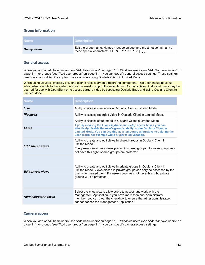
RC-P / RC-I / RC-C User Manual Advanced configuration
On-Net Surveillance Systems, Inc. 113
Group information
Name Description
Group name Edit the group name. Names must be unique, and must not contain any of these special characters: < > & ' " \ / : * ? | [ ]
General access
When you add or edit basic users (see "Add basic users" on page 110), Windows users (see "Add Windows users" on page 111) or groups (see "Add user groups" on page 111), you can specify general access settings. These settings need only be modified if you plan to access video using Ocularis Client in Limited Mode.
When using Ocularis, typically only one user is necessary on a recording component. This user should have full administrator rights to the system and will be used to import the recorder into Ocularis Base. Additional users may be desired for use with OpenSight or to access camera video by bypassing Ocularis Base and using Ocularis Client in Limited Mode.
Name Description
Live Ability to access Live video in Ocularis Client in Limited Mode.
Playback Ability to access recorded video in Ocularis Client in Limited Mode.
Setup
Ability to access setup mode in Ocularis Client in Limited Mode.
Tip: By clearing the Live, Playback and Setup check boxes you can effectively disable the user's/group's ability to use Ocularis Client in Limited Mode. You can use this as a temporary alternative to deleting the user/group, for example while a user is on vacation.
Edit shared views
Ability to create and edit views in shared groups in Ocularis Client in Limited Mode.
Every user can access views placed in shared groups. If a user/group does not have this right, shared groups are protected.
Edit private views
Ability to create and edit views in private groups in Ocularis Client in Limited Mode. Views placed in private groups can only be accessed by the user who created them. If a user/group does not have this right, private groups will be protected.
Administrator Access
Select the checkbox to allow users to access and work with the Management Application. If you have more than one Administrator member, you can clear the checkbox to ensure that other administrators cannot access the Management Application.
Camera access
When you add or edit basic users (see "Add basic users" on page 110), Windows users (see "Add Windows users" on page 111) or groups (see "Add user groups" on page 111), you can specify camera access settings.

Advanced configuration RC-P / RC-I / RC-C User Manual
114 On-Net Surveillance Systems, Inc.
When using Ocularis, typically only one user is necessary on a recording component. This user should have full administrator rights to the system and will be used to import the recorder into Ocularis Base. All cameras should be available to the account used to import the recorder into Ocularis Base.
In the list of cameras, select the camera(s) you want to work with. Note the last item in the list, Rights for new cameras when added to the system, with which you can allow the user/group access to any future cameras.
Tip: If the same features should be available for access for several cameras, you can select multiple cameras by pressing SHIFT or CTRL on your keyboard while you select.
For the selected camera(s), in the Access check box, specify if the user/group should have access to live viewing and playback at all. If so, specify if they should have access to both live viewing and playback and—if this is the case—which sub-features should be available when you work with the selected camera(s). The sub-features are listed in two columns in the lower part of the window: the left column lists features related to live viewing, the right column lists features related to playback.
The Camera access settings check boxes work like a hierarchy of rights. If the Access check box is cleared, everything else is cleared and disabled. If the Access check box is selected, but, for example, the Live check box is cleared, everything under the Live check box is cleared and disabled.
For Ocularis, we recommend checking all boxes for all cameras as privileges are refined in Ocularis Base.
Depending on the selected column, the following default features for live or playback from the selected camera(s) give you the ability to:
Properties available in RC-P, RC-I and RC-C:
Live Features
PTZ Use navigation features for PTZ (Pan-tilt-zoom) cameras.
A user/group can only use this right if the user has access to one or more PTZ cameras.
PTZ preset positions Use navigation features for moving a PTZ camera to particular preset positions. A user/group can only use this right if the user/group has access to one or more PTZ cameras with defined preset positions.
Manage PTZ presets This feature is currently unavailable.
Output Activate output (lights, sirens, door openers, etc.) related to the selected camera(s).
Events This feature is unavailable.
Incoming audio Listen to incoming audio from microphones related to the selected camera(s).
Manual recording Manually start recording for a fixed time (defined (see "Manual recording" on page 53) by the surveillance system administrator).
Properties available in RC-C and RC-I only:
Outgoing audio Talk to audiences through speakers related to the selected camera(s).

RC-P / RC-I / RC-C User Manual Advanced configuration
On-Net Surveillance Systems, Inc. 115
Properties available in all RC-P, RC-I and RC-C:
Playback Features
AVI/JPEG export Export evidence as movie clips in AVI format and as still images in JPEG format.
Database export Export evidence in database format.
Sequences Use the Sequences feature when playing back video from the selected camera.
Smart search Search for motion in one or more selected areas of images from the selected camera.
Recorded audio Listen to recorded audio from microphones related to the selected camera(s).
You cannot select a feature, if the selected camera does not support the relevant feature. For example, PTZ-related rights are only available if the relevant camera is a PTZ camera. Some features depend on the user’s/group’s General Access (on page 113) properties.
Square-filled check boxes can appear in the lower part of the window if you have selected several cameras and a feature applies for some but not all of the cameras. Example: For camera A, you have selected that use of the Events is allowed, for camera B, you have not allowed this. If you select both camera A and camera B in the list, the Events check box in the lower part of the window is square-filled. Another example: Camera C is a PTZ camera for which you have allowed the PTZ preset positions feature whereas camera D is not a PTZ camera. If you select both camera C and camera D in the list, the PTZ preset positions check box is square-filled.
Services
About services
The following services are all automatically installed on the RC-P / RC-I / RC-C server if you run a Typical installation. By default, services run transparently in the background on the RC-P / RC-I / RC-C server. If you need to, you can start and stop services separately from the Management Application, see Start and stop services (on page 116).
Service Description
OnSSI Recording Server service A vital part of the surveillance system. Video streams are only transferred to RC-P / RC-I / RC-C while the Recording Server service is running.
OnSSI Image Server service
Provides access to the surveillance system for users who log in with Ocularis Client.
Note: If the Image Server service is configured in Windows Services to log in with another account than the Local System account, for example as a domain user, installed instances of Ocularis Client on other computers than the surveillance server itself are not able to log in to the server using the server's host name. Instead, those users must enter the server's IP address.
OnSSI Image Import service
Used for fetching pre- and post-alarm images, and storing the fetched images in camera databases. Pre- and post-alarm images is a feature available for selected cameras only that enables sending of images from immediately before and after an event took place from the camera to the surveillance system via e-mail. Pre- and post-alarm images should not be confused with the RC-P / RC-I / RC-C pre- and post-recording feature (see "Recording" on page 64).

Advanced configuration RC-P / RC-I / RC-C User Manual
116 On-Net Surveillance Systems, Inc.
Service Description
OnSSI Log Check service Performs integrity checks on RC-P / RC-I / RC-C log files. For more information, see Overview of Logs.
Start and stop services
On an RC-P / RC-I / RC-C server, several services (see "About services" on page 115) by default run in the background. If you need to, you can start and stop each service separately:
1. In the Management Application's Navigation pane, expand Advanced Configuration and select Services. This displays the status of each service.
2. You can now stop each service by clicking the Stop button. When a service is stopped, the button changes to Start, allowing you to start the service again when required.
Tip: Occasionally, you may want to stop a service and start it again immediately after. The Restart button allows you to do just that with a single click.
RC-P / RC-I / RC-C User Manual Backup and restore configuration
On-Net Surveillance Systems, Inc. 117
Backup and restore configuration
About backup and restore of configurations
OnSSI recommends that you make regular backups of your RC-P / RC-I / RC-C configuration (cameras, schedules, views, and so on) as a disaster recovery measure. While it is rare to lose your configuration, it can happen under unfortunate circumstances. Luckily, it takes only a minute to back up your existing configuration.
Back up system configuration
The following describes how to back up your configuration in RC-P / RC-I / RC-C 7.0 or later. If you need information about how to back up a configuration from an earlier version of RC-P / RC-I / RC-C see Upgrade from a previous version (on page 10).
In the following, we assume that you have not changed your system's default configuration path (see "Default File Paths" on page 20), which is C:\Program Data\OnSSI\Recorder_Name on servers running all supported operating systems. If you have changed the default configuration path, you must take your changes into consideration when using the method described in the following.
The backup described here is a backup of your entire surveillance system setup. Alternatively, you can export your configuration as a backup (see "Export and import management application configuration" on page 119), which is limited to the Management Application configuration.
To back up:
1. Make a copy of the folder C:\Program Data\OnSSI\OnSSI RC-P / RC-I / RC-C and all of its contents.
2. Open the folder C:\Program Files\OnSSI\OnSSI RC-P / RC-I / RC-C, and verify if the file devices.ini exists. If the file exists, make a copy of it. The file exists if you have configured video properties (see "General" on page 60) for certain types of cameras. For such cameras, changes to the properties are stored in the file rather than on the camera itself.
3. Store the copies away from the server, so that they are not affected if the server is damaged, stolen or otherwise affected.
Remember that a backup is a snapshot of your system configuration at the time of backing up. If you later change your configuration, your backup does not reflect the most recent changes. Therefore, back up your system configuration regularly.
Tip: When you back up your configuration as described, the backup includes restore points (see "Restore system configuration from a restore point" on page 120). This allows you to not only restore the backed-up configuration, but also to revert to an earlier point in that configuration if you need to.
Restore system configuration on the Same Server
1. If RC-P / RC-I / RC-C is used on a server running any supported operating system, copy the contents of the backed-up data into C:\Program Data\OnSSI\RC-P / RC-I / RC-C.
2. If you backed up the file devices.ini, copy the file into C:\Program Files\OnSSI\RC-P / RC-I / RC-C\devices.

Backup and restore configuration RC-P / RC-I / RC-C User Manual
118 On-Net Surveillance Systems, Inc.
Move a Recorder Configuration From One Server to Another Server
Use this procedure when you need to move the full configuration of an existing recorder to a new recorder.
Note: The information in the online help for RC-P, RC-I or RC-C is not sufficient for a successful move. Use these steps instead.
1. On the destination server, install the recording component software. Be sure to install the same version software that exists on the original system.
2. Stop all OnSSI services on both new and old systems. These include:
a. OnSSI Service Control service b. OnSSI Recording Server service c. OnSSI Log Check Service service d. OnSSI Image Server service e. OnSSI Notification Server service
f. OnSSI Image Import Service service
3. Copy the following directory from the old server to the new server:
%ProgramData%\OnSSI\RC-P_RC-I_RC-C
(For versions prior to 2.6/8.6, the directory structure will be: %ProgramData%\OnSSI\RC-X where X
is the model recorder such as P, I or C)
Note: You may receive a message about ‘PreAlarmRoot’. If so, click Skip.
4. On the destination server, start the ‘OnSSI Recording Server‘ service. This will also automatically start the OnSSI Service Control Service.
Starting this service creates the necessary folder structure on the destination computer to be used in step 6 below.
5. Now, stop the ‘OnSSI Recording Server’ service and the OnSSI Service Control service (that you just started).
6. Copy the file ‘devices.ini’ from the old server:
%ProgramData%\VideoDeviceDrivers\...remainder of the path of the recorder
The default location would be:
C:\ProgramData\VideoDeviceDrivers\C_\Program Files (x86)\OnSSI\DevicePack\devices
to the same corresponding location on the new server.
7. Restart all OnSSI Services on the new server.
a. OnSSI Service Control service b. OnSSI Recording Server service c. OnSSI Log Check Service service

RC-P / RC-I / RC-C User Manual Backup and restore configuration
On-Net Surveillance Systems, Inc. 119
d. OnSSI Image Server service e. OnSSI Notification Server service
f. OnSSI Image Import Service service
8. In Ocularis Administrator Servers / Event tab, select the old recording server and click Edit.
9. Change the IP address of the old server to the new one. Don’t forget to include the port number. (Default port number is 81).
10. Click Update.
Export and import management application configuration
You can export the current configuration of your RC-P / RC-I / RC-C Management Application, either as a safety measure in order to have a backup file of your configuration, or as a clone allowing you to use a similar Management Application configuration elsewhere. You can, at a later time, import previously exported Management Application configurations.
Export Management Application configuration as backup
With this option, all relevant RC-P / RC-I / RC-C Management Application configuration files are combined into one single .xml file, which you can specify a location for. Note that if there are unsaved changes to your configuration, these are automatically saved when you export the configuration.
1. In the Management Application's File menu, select Export Configuration - Backup.
2. Browse to the location at which you want to store the exported configuration, specify a suitable file name, and click Save.
If you intend to set up an identical version of your surveillance system elsewhere, do not export your configuration as backup, since this may lead to the same device information being used twice, in which case clients may get the following error message: Application is not able to start because two (or more) cameras are using the same name or ID. Instead, export your configuration as a clone. When you export as a clone, the export takes into account the fact that you are not using the exact same physical cameras, etc. even though your new system may otherwise be identical to your existing one.
Note that there is a difference between this Management Application configuration backup and the system configuration backup done from the OnSSI Surveillance folder because these are two different things. The backup described here is limited to a backup of the Management Application configuration. The type of system configuration backup done from the OnSSI Surveillance folder is a backup of your entire surveillance system setup (including, among other things, log files, event configuration, restore points, view groups as well as the Management Application and Ocularis Client configuration).
When you install the new version of RC-P / RC-I / RC-C, it inherits the configuration from the corresponding previous version.
OnSSI recommends that you make regular backups of your server configuration as a disaster recovery measure. You should also do this when you upgrade your server. While it is rare that you lose your configuration (cameras, schedules, views, etc), it can happen under unfortunate circumstances. Fortunately, it takes only a minute to back up your existing configuration.
Export Management Application configuration as clone
With this option, all relevant RC-P / RC-I / RC-C Management Application configuration files are collected, and GUIDs (Globally Unique IDentifiers, unique 128-bit numbers used for identifying individual system components, such as cameras) are marked for later replacement. GUIDs are marked for later replacement because they refer to specific components (cameras, etc.). Even though you wish to use the cloned configuration for setting up a new similar system using similar types of cameras, the new system does not use the exact same physical cameras as the cloned system. When you use the cloned configuration later in a new system, the GUIDs are replaced with GUIDs representing the specific components of the new system.
Backup and restore configuration RC-P / RC-I / RC-C User Manual
120 On-Net Surveillance Systems, Inc.
After you have marked GUIDs for replacement, the configuration files are combined into one single .xml file, which you can then save at a location specified by you. Note that if there are unsaved changes to your configuration, they are automatically saved when you export the configuration.
1. In the Management Application's File menu, select Export Configuration - Clone.
2. Browse to the location at which you want to store the exported configuration, specify a suitable file name, and click Save.
Import previously exported Management Application configuration
The same import method is used regardless of whether the Management Application configuration was exported as a backup or a clone.
1. In the Management Application's File menu, select Import Configuration.
2. Browse to the location from which you want to import the configuration, select the relevant configuration file, and click Open.
3. Only relevant if the system into which you import the configuration contains devices (cameras, etc.) which are not present in the imported configuration: you are asked whether you want to delete or keep recordings from affected devices. If you want to keep the recordings, note that they are not accessible until you add the affected devices to RC-P / RC-I / RC-C again. Select the option you need, and click OK.
4. In the Management Application's navigation pane, expand Advanced Configuration, and select Services.
5. For the Recording Server and Image Server services respectively, click the Restart button. Restarting the two services applies the imported Management Application configuration.
Import changes to configuration
It is possible to imported changes to a configuration. This can be relevant if installing many similar RC-P / RC-I / RC-C systems, for example in a chain of shops where the same types of server, hardware devices, and cameras are used in each shop. In such cases, you can use an existing configuration—typically a cloned configuration (see "Export and import management application configuration" on page 119)—as a template for the other installations. However, since the shops' installations are not exactly the same (the hardware devices and cameras are of the same type, but they are not physically the same, and therefore they have different MAC addresses), there needs to be an easy way of importing changes to the template configuration.
This is why RC-P / RC-I / RC-C lets you import changes about hardware devices and cameras as comma-separated values (CSV) from a file (see "Add hardware: Import from CSV file - CSV file format and requirements" on page 25):
1. From the menu bar, select File > Import Changes to Configuration...
2. Select Online verification if the new hardware devices and cameras listed in your CSV file are connected to the server and you want to verify that they can be reached.
3. Point to the CSV file, and click the Import Configuration from File button.
Restore system configuration from a restore point
Restore points allow you to return to a previous configuration state. Each time you apply a configuration change in the Management Application—either by clicking OK in a properties dialog or by clicking the Apply button in a summary pane—a new restore point is created.
All restore points in the current and previous five sessions are stored and can be selected again. A new session begins each time you start the Management Application as well as each time you save the whole configuration, for example by clicking the Save Configuration button in the Management Application's toolbar. For sessions older than the last five sessions, only the latest restore point of each session is stored. With the Number of old sessions to keep field, you can control how many old sessions are kept.
When you select to restore a configuration from a restore point, the configuration from the selected restore point is applied and used once the services are restarted (see Start and stop services (on page 116)).

RC-P / RC-I / RC-C User Manual Backup and restore configuration
On-Net Surveillance Systems, Inc. 121
If you have added new cameras or other devices to RC-P / RC-I / RC-C after the restore point was created, they are missing if you load the restore point. This is because they were not in the system when the restore point was created. In such cases, you are notified and must decide what to do with recordings from the affected devices.
1. From the Management Application's File menu, select Load Configuration from Restore Point...
2. In the left part of the Restore Points dialog, select the required restore point.
3. Click the Load Restore Point button.
4. If you are sure that you want to overwrite the current configuration with the one from the selected restore point, click OK.
5. Only relevant if the current configuration contains cameras or other devices which were not present in the selected restore point: you are asked whether you want to delete or keep recordings from affected devices. If you keep the recordings, note that they are not be accessible until you add the affected devices to RC-P / RC-I / RC-C again. Select the relevant option, and click OK.
6. Click OK in the Restore Points dialog.
7. In the Management Application's navigation pane, expand Advanced Configuration, and select Services.
8. For the Recording Server and Image Server services respectively, click the Restart button. When the two services are restarted, the configuration from the selected restore point is applied.
Tip: When you select a restore point, you can see information about the configuration state at the selected point in time in the right part of the dialog. This can help you select the best possible restore point.
Miscellaneous Concepts and Tasks RC-P / RC-I / RC-C User Manual
122 On-Net Surveillance Systems, Inc.
Miscellaneous Concepts and Tasks
About protecting recording databases from corruption
In the Management Application, you can select which action to take if a camera database becomes corrupted. The actions include several database repair options. While being able to select such actions is highly valuable, it is of course even better to take steps to ensure that your camera databases do not become corrupted.
Power outages: use a UPS
The single-most common reason for corrupt databases is the recording server being shut down abruptly, without files being saved and without the operating system being closed down properly. This may happen due to power outages, due to somebody accidentally pulling out the server's power cable, or similar.
The best way of protecting your recording servers from being shut down abruptly is to equip each of your recording servers with a UPS (Uninterruptible Power Supply).
The UPS works as a battery-driven secondary power source, providing the necessary power for saving open files and safely powering down your system in the event of power irregularities. UPSs vary in sophistication, but many UPSs include software for automatically saving open files, for alerting system administrators, etc.
Selecting the right type of UPS for your organization's environment is an individual process. When you assess your needs, however, bear in mind the amount of runtime you require the UPS to be able to provide if the power fails. Saving open files and shutting down an operating system properly may take several minutes.
Windows Task Manager: be careful when you end processes
When you work in Windows Task Manager, be careful not to end any processes which affect the surveillance system. If you end an application or system service by clicking End Process in the Windows Task Manager, the process is not be given the chance to save its state or data before it is terminated. This may lead to corrupt camera databases.
Windows Task Manager will typically display a warning if you attempt to end a process. Unless you are absolutely sure that ending the process is not going to affect the surveillance system, click No when the warning message asks you if you really want to terminate the process.
Hard disk failure: protect your drives
Hard disk drives are mechanical devices and are vulnerable to external factors. The following are examples of external factors which may damage hard disk drives and lead to corrupt camera databases:
Vibration (make sure the surveillance system server and its surroundings are stable)
Strong heat (make sure the server has adequate ventilation)
Strong magnetic fields (avoid)
Power outages (make sure you use a UPS)
Static electricity (make sure you ground yourself if you are going to handle a hard disk drive).
Fire, water, etc. (avoid)
Monitor storage space usage
To view how much storage space you have on your system—and not least how much of it is free—do the following:
1. In the Management Application's navigation pane, expand Advanced Configuration, and select Cameras and Storage Information.
2. View the Storage Usage Summary for information about, which drives are available, what drives are used for, the size of each drive, as well as how much video data, other data, and free space there is in each drive.
RC-P / RC-I / RC-C User Manual Miscellaneous Concepts and Tasks
On-Net Surveillance Systems, Inc. 123
View video from cameras in Management Application
You can view live video from single cameras directly in the Management Application:
1. In the Management Application navigation pane, expand Advanced Configuration, and expand Cameras and Storage Information.
2. Select the relevant camera to view live video from that camera. Above the live video, you find a summary of the most important properties for the selected camera. Below the live video, you find information about the camera's resolution and average image file size. For cameras using MPEG or H.264, you also see the bit rate in Mbit/second.
IMPORTANT: Viewing of live video in the Management Application may under certain circumstances affect any simultaneous recording from the relevant camera. Especially three scenarios are important to consider:
- Some cameras supporting multistreaming may halve their frame rate or respond with other negative effects if you open a second stream.
- If a camera delivers live video in a very high quality, de-coding of images may increase the load on the Recording Server service, which may in turn affect ongoing recordings negatively.
- Cameras that do not support multiple simultaneous video streams cannot connect to the surveillance server and the Management Application at the same time. Therefore, we recommend that you stop (see "Start and stop services" on page 116) the Recording Server service when you configure such devices for motion detection and PTZ.
Index RC-P / RC-I / RC-C User Manual
124 On-Net Surveillance Systems, Inc.
Index
3
360° lens • 70
A
About activating licenses • 15, 16, 18
About activating licenses after grace period • 17
About archiving • 12, 20, 27, 29, 30, 31, 32, 36, 39,
43, 47, 48, 50, 58, 66, 87, 94, 101, 103
About archiving audio • 89
About archiving locations • 88
About archiving schedules • 87, 90
About archiving to other locations • 88
About automatic device discovery • 18, 19
About backup and restore of configurations • 117
About database resizing • 43
About dedicated input/output devices • 37, 81
About dynamic archive paths • 88
About email • 101
About events and output • 76
About handling daylight saving time • 8
About hardware devices • 36
About input and output • 75
About licenses • 15
About logs • 97
About master and slave • 108
About microphones • 36, 74
About motion detection and PTZ cameras • 43, 45
About motion detection settings • 43, 45, 68
About NetCentral • 105
About NetMatrix video sharing • 96
About NetMatrix-recipients • 97
About notifications • 79, 92, 100
About protecting recording databases from corruption
• 67, 121
About recording audio • 36
About registered services • 106
About replacing cameras • 16
About replacing hardware devices • 37
About restarting services • 13
About saving changes to the configuration • 13
About scheduling • 87
About scheduling of notifications • 105
About server access • 106
About services • 43, 106, 116
About SMS • 103
About speakers • 36
About the built-in help • 13
About the Getting started page • 21
About upgrading • 10
About users • 111
About video and recording configuration • 12, 42, 44,
46, 48, 49, 53, 54, 56, 58, 59, 60, 61, 64, 65, 67,
68, 74, 88, 95
Access summary • 35
Add a generic event • 77, 79
Add a hardware input event • 77, 81
Add a hardware output • 67, 75, 77, 78, 80, 82
Add a manual event • 77, 78, 82
Add a timer event • 77, 78, 79, 82, 83, 86

RC-P / RC-I / RC-C User Manual Index
On-Net Surveillance Systems, Inc. 125
Add basic users • 13, 107, 111, 112, 113, 114
Add hardware
Import from CSV file - CSV file format and requirements • 23, 25, 119
Scanning options • 23
Select hardware manufacturers to scan for • 23
Add Hardware Devices wizard - Import from CSV File
- example of CSV file • 24
Add hardware wizard • 12, 22, 36, 37
Add user groups • 13, 34, 107, 111, 112, 113, 114
Add Windows users • 111, 112, 113, 114
Adjust motion detection wizard • 32
Administrator rights • 7
Advanced configuration • 36
Archiving • 90, 92, 94, 101, 103
Attachment Settings (email) • 102
Audio • 64
Audio recording • 58
Audio selection • 59
Automatic configuration wizard • 12, 21
Continue after scan • 9
First page • 21
Scanning for hardware devices • 21
Scanning options • 21
Select hardware manufacturers to scan for • 21
Automatic response if running out of disk space • 90
B
Back up system configuration • 11, 117
Back up your current configuration • 10
Backup and restore configuration • 117
Basic and Windows users • 35
Before you start • 7
C
Camera access • 94, 111, 112, 113, 114
Camera and database action • 38, 39
Camera properties • 60
Cameras and storage information • 42
Camera-specific scheduling properties • 95
Change default file paths • 18
Change SLC • 17
Configure camera-specific schedules • 12, 44, 45, 93,
95, 96
Configure email notifications • 81, 82, 83, 86, 101
Configure general event handling • 77, 80, 84
Configure general scheduling and archiving • 12, 45,
92, 94
Configure hardware devices • 37, 40, 41
Configure hardware output on event • 75, 77, 78, 80,
87
Configure master and slave servers • 109
Configure microphones or speakers • 74
Configure motion detection • 45
Configure NetMatrix • 97
Configure server access • 34, 107, 109
Configure SMS notifications • 82, 83, 86, 103
Configure storage
Online schedule • 26
Video settings and preview • 26
Configure storage wizard • 25, 90
Configure system, event and audit logging • 99
Configure user and group rights • 13, 34, 35, 39, 53,
65, 67, 70, 78, 107, 111, 112, 113
Configure when cameras should do what • 45

Index RC-P / RC-I / RC-C User Manual
126 On-Net Surveillance Systems, Inc.
Copyright, trademarks and disclaimer • 6
D
Default File Paths • 20, 88, 89, 117
Delete hardware devices • 38, 46
Disable or delete cameras • 46
Drive selection • 30
Dynamic path selection • 20, 43, 48, 67
E
Email • 101
Email (Properties) • 95, 101
Enable NetCentral • 106
Events and output • 75
Events and output properties • 81
Exclude regions • 33, 45
Export and import management application
configuration • 117, 119
Express • 22
F
First time use • 12
Frame rate - MJPEG • 54, 96
Frame Rate - MPEG • 56
G
General • 19, 29, 49, 60, 64, 68, 117
General access • 111, 112, 113, 115
General event properties • 80
General scheduling properties • 92
Generic event • 79, 84
Get your system up and running • 10, 12
Getting started • 21
Group information • 113
H
Hardware detection and verification • 23
Hardware devices • 36
Hardware input event • 78, 79, 81
Hardware name and video channels • 40
Hardware output • 82
Hardware properties • 40
I
If the camera uses the MJPEG video format • 50
If the camera uses the MPEG video format • 52
Import changes to configuration • 119
Import from CSV file • 11, 22, 24
Important port numbers • 7
Information, driver selection and verification • 24
Install and upgrade • 10
Install your surveillance server software • 10, 12
L
Licenses • 15
Live and recording settings Motion-JPEG cameras •
27
Live and recording settings MPEG cameras • 28
Local IP ranges • 107, 108
Log properties • 99
Logs • 97
M
Manage user access wizard • 13, 34, 106, 111, 112,
113
Manual • 22, 23
Manual event • 82
Manual recording • 53, 65, 115

RC-P / RC-I / RC-C User Manual Index
On-Net Surveillance Systems, Inc. 127
Master/Slave • 108
Master/slave properties • 110
Message Settings (email) • 101, 105
Message Settings (SMS) • 104, 105
Microphone (properties) • 74
Microphones • 74
Minimum system requirements • 7
Miscellaneous Concepts and Tasks • 121
Monitor storage space usage • 121
Motion Detection • 33
Motion detection & exclude regions • 29, 45, 49, 56,
58, 65, 68, 78, 101, 103
Move PTZ type 1 and 3 to required positions • 46, 70
N
NetCentral • 105
NetCentral properties • 106
NetMatrix • 96
Network, device type, and license • 37, 40
New hardware device information • 38
Notification Scheduling properties • 102, 104, 105
Notifications • 100
O
Online period • 29, 46, 49, 60, 64, 78, 94, 95
Options • 19
Output • 67, 78
Output control on event (Events and Output-specific
properties) • 80, 87
Overview of events and output • 76
Overview of license information • 15
P
Ports and polling • 37, 80
Privacy masking • 69
PTZ device • 37, 41
PTZ on event • 73, 78
PTZ patrolling • 44, 71, 72, 93, 96
PTZ preset positions • 70, 71, 73
R
Recording • 43, 49, 53, 54, 56, 64, 81, 116
Recording and archiving paths • 20, 46, 65, 87
Recording and archiving settings • 31
Recording and storage properties • 46
Regular frame rate properties • 55
Remove system components • 11
Remove the current version • 11
Replace Hardware Device wizard • 15, 16, 37, 38, 41
Restore system configuration • 117
Restore system configuration from a restore point •
13, 117, 119
S
Scheduling • 105
Scheduling all cameras • 92
Scheduling and archiving • 87
Scheduling options • 26, 92, 94, 95, 96
Server access • 7, 106, 107
Server access properties • 107
Server Settings (email) • 102
Server Settings (SMS) • 104
Services • 116
Settings • 18
Index RC-P / RC-I / RC-C User Manual
128 On-Net Surveillance Systems, Inc.
Show or hide microphones or speakers • 74
SMS • 103
SMS properties • 95, 103, 104
Speaker properties • 42, 74
Speedup • 52, 56, 58, 62, 96
Speedup frame rate properties • 55
Start and stop services • 18, 33, 38, 40, 68, 70, 71,
74, 116, 119, 122
Storage capacity required for archiving • 89
Storage information • 60
T
Template and common properties • 54
Time server use recommended • 8
Timer event • 79, 83
U
Upgrade • 10
Upgrade from a previous version • 10, 12, 117
User information • 113
User Interface • 20
User properties • 113
Users • 111
V
Video • 57, 61, 96
Video device drivers • 11
Video recording • 49
View archived recordings • 92
View video from cameras in Management Application
• 122
Virus scanning • 8, 92


![Reserve Component Cyber Certification Outreachweb.cse.msstate.edu/~hamilton/P3I/resources/RC... · CEH certification. The CEHv9 certification is built around eighteen modules [8]](https://img.dokumen.tips/doc/110x75/5f05cbe47e708231d414c078/reserve-component-cyber-certification-hamiltonp3iresourcesrc-ceh-certification.jpg)


![Portable Stereo Component System RX-CT65€¦ · To resume recording, press [ PAUSE] again. • Changes to volume and tone will not affect the recording. • Wind up the leader tape](https://img.dokumen.tips/doc/110x75/5fa31c9417762b49311983ed/portable-stereo-component-system-rx-ct65-to-resume-recording-press-pause-again.jpg)