Embed Size (px)
Citation preview

Application Note
Keysight EEsof EDA Recommendations for Port Setup When Using ADS Momentum and Modelithics Models

02 | Keysight | Recommendations for Port Setup When Using ADS Momentum and Modelithics Models - Application Note
Overview
With the increased complexity of today’s circuits, designers are increasingly dependent on electromagnetic (EM) simulations during the design phase. With the trend toward smaller circuits and multi-layered boards, EM simulation is needed to accurately model internal circuit interactions. The use of discrete compo-nents helps to reduce a circuit’s overall footprint, but introduces a level of complexity to the design process. A good understand-ing of the proper EM port configurations and calibration types is required to ensure accurate EM-circuit co-simulation results.
This application note is intended to help users of Keysight Tech-nologies’ Advanced Design System (ADS) and Modelithics mod-els, accurately and efficiently simulate RF and microwave circuits. The focus is on finding the optimum port setup for EM simulation of circuit layouts that include surface mount devices.
Several new features and improvements were introduced to Momentum, the 3D planar EM simulator in ADS, starting with the ADS 2011 release. Of particular interest are the new port calibration types and their impact on co-simulation when using Modelithics models. This application note explains the port nomenclature in ADS, presents multiple co-simulations between Momentum and Modelithics models, shows the impact of the various port shapes and calibration types, and provides recom-mendations based on comparisons to measured data.
The application note content is organized into three main areas. The first area provides detailed information concerning Momen-tum port types and calibration definitions. Next is the results section, which includes examples that provide insight into port and calibration performance. The final section contains the rec-ommended calibration type and port configurations.
Figure 1: Momentum layout pin types: point, edge and area
Pins and Ports in ADS
ADS 2011 introduced new port calibration types and nomencla-ture to Momentum. Before discussing port calibration types, it helps to understand the difference between a pin and a port. A layout pin (or simply “pin”) refers to a specific location in the lay-out and is defined as a single point, an edge, or an area, as shown in Figure 1. The blue color denotes a pin in all three cases; it may be difficult to see the point pin in Figure 1 since the blue color is just a dot at the tip of the arrow.
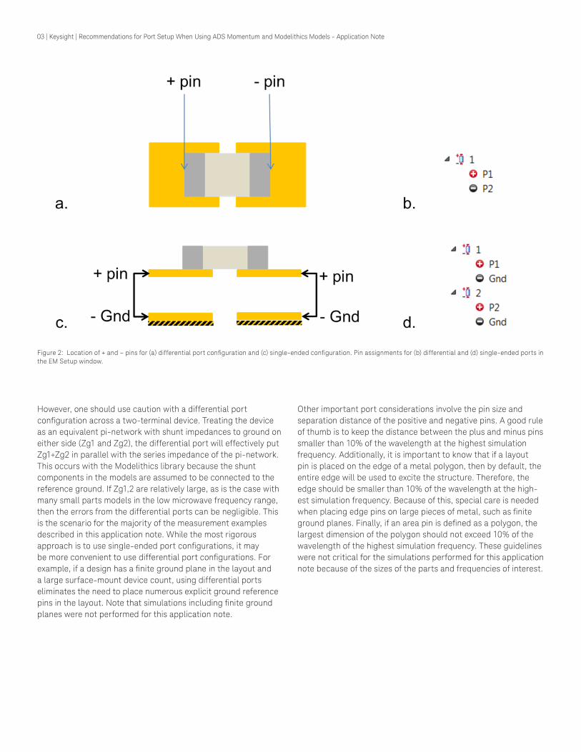
In a Momentum simulation, the user may combine pins together in various configurations to create S-parameter ports. For exam-ple, a user could define one positive pin and two negative pins combined together into a single port, yielding a Ground-Signal-Ground (GSG) configuration for coplanar waveguide structures. This is possible because Momentum supports S-parameter ports with multiple positive pins and/or multiple negative pins. The ground reference for an S-parameter port can be either explicit (Figure 2b) or implicit (Figure 2d). Explicit means that one or more pins set the location of the ground reference for that port. Implicit ground (denoted by Gnd in the EM Setup view) means that there is no layout pin denoting the location of ground; causing Momen-tum to use the nearest infinite ground plane. In the absence of an infinite ground plane, Momentum will use the zero scalar poten-tial at infinity (i.e., ground at infinity). What this means is that you have a choice when co-simulating Momentum and two-terminal Modelithics models: you either set up a single port spanning across the device (Figure 2a, denoted as the differential configu-ration) or set up two ports (one on each pad), each referenced to the nearest ground plane (Figure 2c, denoted as the single-ended configuration).
03 | Keysight | Recommendations for Port Setup When Using ADS Momentum and Modelithics Models - Application Note
Figure 2: Location of + and – pins for (a) differential port configuration and (c) single-ended configuration. Pin assignments for (b) differential and (d) single-ended ports in the EM Setup window.
However, one should use caution with a differential port configuration across a two-terminal device. Treating the device as an equivalent pi-network with shunt impedances to ground on either side (Zg1 and Zg2), the differential port will effectively put Zg1+Zg2 in parallel with the series impedance of the pi-network. This occurs with the Modelithics library because the shunt components in the models are assumed to be connected to the reference ground. If Zg1,2 are relatively large, as is the case with many small parts models in the low microwave frequency range, then the errors from the differential ports can be negligible. This is the scenario for the majority of the measurement examples described in this application note. While the most rigorous approach is to use single-ended port configurations, it may be more convenient to use differential port configurations. For example, if a design has a finite ground plane in the layout and a large surface-mount device count, using differential ports eliminates the need to place numerous explicit ground reference pins in the layout. Note that simulations including finite ground planes were not performed for this application note.
Other important port considerations involve the pin size and separation distance of the positive and negative pins. A good rule of thumb is to keep the distance between the plus and minus pins smaller than 10% of the wavelength at the highest simulation frequency. Additionally, it is important to know that if a layout pin is placed on the edge of a metal polygon, then by default, the entire edge will be used to excite the structure. Therefore, the edge should be smaller than 10% of the wavelength at the high-est simulation frequency. Because of this, special care is needed when placing edge pins on large pieces of metal, such as finite ground planes. Finally, if an area pin is defined as a polygon, the largest dimension of the polygon should not exceed 10% of the wavelength of the highest simulation frequency. These guidelines were not critical for the simulations performed for this application note because of the sizes of the parts and frequencies of interest.

04 | Keysight | Recommendations for Port Setup When Using ADS Momentum and Modelithics Models - Application Note
Momentum Port Calibration Types
TML The TML port calibration (known as Single Mode in earlier ver-sions of ADS) is used when a transmission line will be connected to the port. For this port calibration type, Momentum extends the transmission line (or any edge of the layout in contact with the port). A calibration standard (a transmission line of twice the length) is simulated to de-embed the effect introduced by the transmission line. This calibration technique reduces the impact of higher-order modes around the source and adds the mutual coupling effect of the transmission line current with the circuit. It is recommended when the circuit is fed through a long transmis-sion line(s).
TML (Zero Length): This calibration can be used for ports connected to short trans-mission lines (or other edges) in a layout. It is used in cases where the transmission line extensions added during TML calibration would intersect with other structures in the layout. For the TML (zero length) calibration, Momentum connects a source direct-ly to the port; no transmission line extensions are added. TML (zero length) only removes the fringe capacitance at the edge of the metal. It does not filter out higher-order modes. Momentum will automatically use TML (zero length) calibration and issues a warning if TML calibration is chosen but the transmission line extension would intersect with other polygons on the same metal layer.
Delta Gap Delta Gap calibration is used to quickly and easily add parasitic effects to an otherwise ideal surface mount device (SMD)— such as R, L or C—model. When using it, two layout pins defining the Delta Gap calibrated port are placed across a gap between the pads; these pins must be placed on the edges of the metal. The port must be defined differentially across the two edge pins. Delta Gap calibration effectively adds a piece of metal extend-ing from each pad inwards, leaving a small gap for the source. Momentum does not de-embed the effects of this metal from the simulation results. This way, some parasitic self-impedance is added as a rudimentary way of modeling the parasitics of the part. This extra bit of metal also models mutual inductive or ca-pacitive coupling between the part and other neighboring traces or parts.
Surface Mount Device When using an SMD port calibration, a pair of pins must be placed on the inner edges of a surface mount device’s pads. The port must be defined differentially across the two edge pins. SMD calibration is intended for use with surface mount device models that already include the parasitics of the part itself (i.e., self-im-pedance). SMD calibration stretches the two pads toward each other, leaving a small gap for the source. This effectively adds a little piece of metal in between the pads to capture the mutual coupling to nearby circuitry. Momentum models the additional metal to create a calibration standard that is used to de-embed the self-impedance of the extended metal; however, the mutu-al impedance (capacitive and/or inductive coupling to nearby circuitry) is not de-embedded from the simulation results. Since this mutual impedance to neighboring traces is not part of typical SMD component models, the SMD calibration can be a simple way to model this effect. The key difference between Delta Gap and SMD calibration is that Delta Gap keeps the self-impedance added by the extra bit of metal, while with SMD it is removed.
None (Uncalibrated) There is also the option to use uncalibrated ports in Momen-tum. These ports were previously called Internal ports in older versions of ADS, but are now simply called None. Uncalibrated ports can be placed anywhere within the circuit (not limited to boundaries between dielectrics and conductors) and may excite a single point, edge or area. Uncalibrated ports may be defined using a single pin referenced to implicit ground (Gnd), or by using multiple positive pins and/or multiple negative pins. Sometimes, uncalibrated ports are the best choice for modeling how devices are connected to a circuit.
For further information concerning calibration types, please refer to the ADS documentation.

05 | Keysight | Recommendations for Port Setup When Using ADS Momentum and Modelithics Models - Application Note
Options for Including Pads in SimulationsModelithics models include a feature that allows for the removal of the pad effects from the model. Simulation mode 2 (Sim_mode 2) provides the designer with the flexibility of using custom pad geometries by including the pads in the EM simulation, while disabling the pads in the Modelithics model. When enabled, this feature effectively shifts the reference planes from the outer pad edge to the component input. The entire pad is removed, includ-ing any portion that extends under the component. It should be noted that the default Sim_mode setting is 0 (zero). In this mode, all parasitics, including pad effects, are included in the model’s performance.
A second feature that affects pad handling is Pad_mode. Pad_mode, in conjunction with Sim_mode, determines whether the pads are included in the layout. When the Pad_mode is set to 0, pad handling defaults to the Sim_mode setting. In other words, with Pad_mode set to 0 and Sim_mode set to 2, the pads are not included in the layout, nor are the effects included in the mod-el. The default Pad_mode setting is 0 (zero). Other Pad_mode and Sim_mode setting configurations will allow the designer to disable the pad effects from the model but include the pads in the layout. This helps reduce the chances of duplicating the pad effects during co-simulation. For more information concerning Pad_mode and Sim_mode, please refer to the Modelithics Library User Manual.
Note that Sim_mode 0 should not be used in conjunction with differential Momentum ports. This includes uncalibrated dif-ferential ports, as well as SMD and Delta Gap calibrated ports. Using Sim_mode 0 along with any of these types of differential ports will likely result in noticeable errors since the device model will include the pads (modeled primarily as shunt capacitance to ground), and differential ports improperly treat this shunt capacitance to ground. Sim_mode 2 should be used with differ-ential ports in most cases or else the capacitance of the pads will effectively reduce the shunt impedance (Zg1,2), thus increasing the likelihood of simulation errors.
ResultsTo explore the differences in Momentum port types, a 4.7-nH Toko 0603 inductor was measured on a 20 mil Rogers substrate in a series configuration. Various Momentum port types were then used and the results were compared. Figure 3 shows the layout that was simulated and fabricated for measurements; the yellow lines represent de-embedding (i.e., reference offset) in Momen-tum. The lead-in transmission lines were de-embedded both in simulation and in measurement, such that the reference plane for the final S-parameters is located at the outermost edges of the tapers. Figure 4 shows the co-simulation schematic, which includes the Modelithics model and the “emModel” for Momen-tum. Note that ADS includes layout look-alike as an option for the schematic symbol; a useful feature that helps visualize all circuit connections and aides in schematic simulations.
Figure 3: ADS layout for Toko 0603 inductor
Figure 4: ADS schematic including the Modelithics model and the Momentum emModel.
Figure 5 shows the S-parameters resulting from setting the calibration type to None and comparing single-ended vs. differ-ential point ports. Note that both configurations give reasonable results, with the differential setup resulting in a slightly closer agreement to measured data.
Figure 5: Comparing differential vs. single-ended ports for a Toko 0603 inductor. LEGEND: solid lines = simulated data, circles = measured data.
06 | Keysight | Recommendations for Port Setup When Using ADS Momentum and Modelithics Models - Application Note
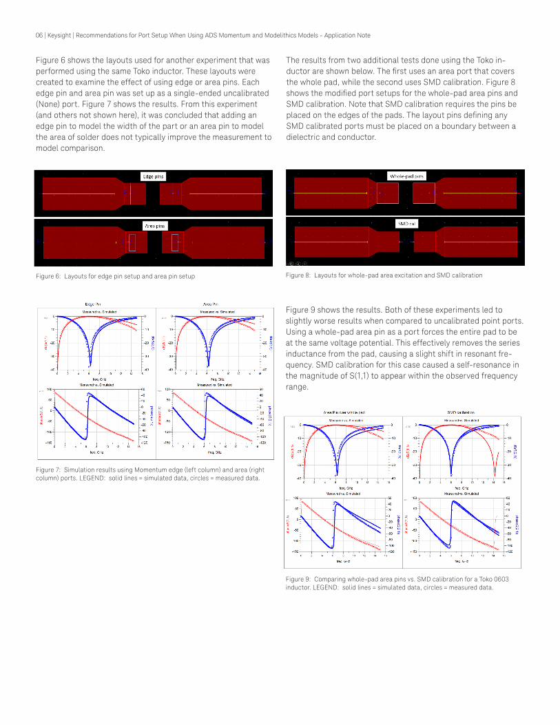
Figure 6 shows the layouts used for another experiment that was performed using the same Toko inductor. These layouts were created to examine the effect of using edge or area pins. Each edge pin and area pin was set up as a single-ended uncalibrated (None) port. Figure 7 shows the results. From this experiment (and others not shown here), it was concluded that adding an edge pin to model the width of the part or an area pin to model the area of solder does not typically improve the measurement to model comparison.
Figure 6: Layouts for edge pin setup and area pin setup Figure 8: Layouts for whole-pad area excitation and SMD calibration
Figure 7: Simulation results using Momentum edge (left column) and area (right column) ports. LEGEND: solid lines = simulated data, circles = measured data.
The results from two additional tests done using the Toko in-ductor are shown below. The first uses an area port that covers the whole pad, while the second uses SMD calibration. Figure 8 shows the modified port setups for the whole-pad area pins and SMD calibration. Note that SMD calibration requires the pins be placed on the edges of the pads. The layout pins defining any SMD calibrated ports must be placed on a boundary between a dielectric and conductor.
Figure 9 shows the results. Both of these experiments led to slightly worse results when compared to uncalibrated point ports. Using a whole-pad area pin as a port forces the entire pad to be at the same voltage potential. This effectively removes the series inductance from the pad, causing a slight shift in resonant fre-quency. SMD calibration for this case caused a self-resonance in the magnitude of S(1,1) to appear within the observed frequency range.
Figure 9: Comparing whole-pad area pins vs. SMD calibration for a Toko 0603 inductor. LEGEND: solid lines = simulated data, circles = measured data.

07 | Keysight | Recommendations for Port Setup When Using ADS Momentum and Modelithics Models - Application Note
Results from a final experiment using the Toko inductor are shown below in Figure 10. Here, TML (zero length) calibrated ports were used and placed on the edge of the pads (the same placement as SMD calibration). Note that the simulation deviates further from measurement than uncalibrated point ports. This is the expected result since placing TML (zero length) ports on the edges of the pads does not reflect the placement of the real part. The actual placement of the part is in the middle of the pads, resulting in some pad length before the part and some pad length after the part. In addition, TML (zero length) removes fringing capacitance from the edge of the pad, which should be included to best emu-late the physical configuration.
Figure 10: Comparing TML (zero length) calibration vs. measured data for Toko 0603 inductor. LEGEND: solid lines = simulated data, circles = measured data.
Similar experiments were performed on a structure with two shunt capacitors. The parts used were ATC 0603 capacitors on a 30 mil Rogers 4003C substrate. The schematic with the Modelithics mod-els and the layout look-alike symbol is shown in Figure 11.
Figure 11: Schematic for co-simulation between Modelithics models and Momen-tum for two shunt capacitor structures
Several port setups are explored below for the shunt capacitor structure, including a comparison of point vs. area excitation. Figure 12 shows a zoomed-in view of an area excitation setup in the layout. Note that the entire pad area was used as a port.
Figure 12: Area port setup. The blue color represents a pin.
Figure 13 shows a comparison between the S-parameters ob-tained from differential point ports, single-ended point ports, and single-ended area ports for the shunt capacitor configuration. The best comparison to the measurement data is obtained using the point differential ports, followed by the point single-ended ports, and finally the area ports. As mentioned previously, using whole-pad area ports causes a shift in the resonant frequency because they force the same voltage potential across the entire pad, eliminating the series inductance of the pads.
Figure 13: Results of the comparison between the differential ports, single-end-ed point ports, and area ports. LEGEND: BLACK circles = measured data, RED = differential ports, BLUE = single-ended ports, MAGENTA = area ports.

08 | Keysight | Recommendations for Port Setup When Using ADS Momentum and Modelithics Models - Application Note
The next results consider a Samsung 01005 capacitor mounted on a 20-mil Rogers 4003C substrate The EM simulation con¬-sists of only the pad geometry (Figure 14) used for the capacitor measurements. In Figure 14, pins 3 and 4 define the connection points to the capacitor, while pins 1 and 2 define the ports for the pads that connect to external circuitry. Three EM simulations were performed for the co-simulation comparisons. The first EM simulation employed single-ended ports for pins 3 and 4, while a second EM simulation employed a differential port between pins 3 and 4. For both the single-ended and differential port test cases, the calibration type was set to None for the port(s) defined by pins 3 and 4. For the SMD calibrated test case, pins 3 and 4 were moved to the interior edges of the pads. The S-parameter calibration type for the ports defined by pins 1 and 2 is TML for all test cases.
Figure 14: Layout of land pad geometry
The co-simulation setup is shown in Figure 15. Following comple-tion of the EM simulation, Momentum stores the EM simulation data results in an emModel view. The schematic representation of the EM model data is the layout look-alike symbol (square pads in Figure 15). The co-simulation is accomplished by placing the symbol in a schematic and setting the Modelithics model Sim_mode equal to 2.
Figure 15: Schematic symbol for co-simulation for the Samsung 01005 capacitor
The results of all three co-simulations are shown in Figure 16. The black circles represent the measured data, the solid red line is the simulated differential port arrangement, the solid blue line is the simulated single-ended port configuration, and the solid magenta line is the simulated SMD calibrated performance. It is apparent that the single-ended and differential port setups yielded similar results to the measured data, while SMD calibration yielded less accurate results.
Figure 16: Co-simulation results vs. measured data using uncalibrated single-end-ed and differential ports and SML cal for a 82-pF Samsung 01005 capacitor on 20-mil Rogers 4003C substrate. (Modelithics model CAP-SAM-01005-001). LEGEND: RED = differential, BLUE = single-ended, MAGENTA = SMD calibration and BLACK circles = measured data.
The results of another experiment testing for differences between single-ended and differential port configurations are shown in Figure 17. It is a simulation of a Coilcraft 0805CS inductor on Rogers 4 mil substrate. The results show how the improper treat-ment of shunt impedance by the differential ports can result in a deviation from measured data.
Figure 17: Co-simulation results vs. measured data using uncalibrated single-end-ed and differential ports for a 3.3 nH Coilcraft 0805 inductor on a 4-mil Rogers 4350C substrate. (Modelithics model IND-CLC-0805-102). LEGEND: RED = differ-ential, BLUE = single-ended, and BLACK circles = measured data.

09 | Keysight | Recommendations for Port Setup When Using ADS Momentum and Modelithics Models - Application Note
A more complicated co-simulation of a bandpass filter is present-ed below (Figure 18). The filter circuit consists of 0402 inductors and 0402 capacitors on a 16-mil thick substrate. The calibration type for all ports was set to None. Two co-simulations were performed in order to compare single-ended and differential port configurations.
Figure 18: ADS Schematic for co-simulation of a bandpass filter
Figure 19 displays the results of the co-simulation for the band-pass filter compared to measured data. The results show very good agreement between the measured data and the co-sim-ulation results. This example demonstrates the accuracy of the co-simulations for a combination of series and shunt inductors and capacitors.
Figure 19: Measured vs. co-simulation of bandpass filter. LEGEND: BLUE = sin-gle-ended, RED = differential, BLACK Circles = measured data
10 | Keysight | Recommendations for Port Setup When Using ADS Momentum and Modelithics Models - Application Note
Recommendations
Based on a large set of sample configurations, of which only a small number have been described herein, the following recom-mendations are made for Momentum port setup:
– Port calibration type should be set typically to None when using Momentum in conjunction with Modelithics models. There are two different port configuration choices when using uncalibrated ports for a two-terminal device: single-ended (each port referenced to ground) or differential (a positive pin is referenced to an explicit negative pin). Differential ports are set across the component (see Figure 2a). One should use caution with a differential configuration since it improperly treats any shunt impedance to ground within the device mod-el. Both single-ended and differential configurations gave reasonable results for the majority of the parts examined for this application note, since most small parts have relatively large internal shunt impedances when compared to their series impedances. However, using differential ports for some parts did result in a noticeable deviation from measured data. Because of this, it is preferable to use single-ended configu-rations when possible. Uncalibrated differential port config-urations across two-terminal Modelithics models can also be considered, especially when a design includes a finite ground plane(s). Differential port configurations are more convenient in the presence of a finite ground(s) since they eliminate the need to place explicit ground reference pins in the layout. Note that the above recommendations and comments apply when using Sim_mode = 2 for the Modelithics models. For Sim_mode = 0, there will be additional shunt capacitance from the pads included in the model, and the use of differ-ential ports in that situation is more likely to result in large errors. Therefore, it is recommended to avoid using differen-tial port configurations in conjunction with Sim_mode = 0.
– For the numerous test cases simulated for this applica-tion note it was found that using edge or area pins to try to model the width of the part or the area of the solder does not improve the results over point pins. Edge ports and small area ports tended to yield similar results as point ports, while area ports covering the whole pad tended to yield results that deviated from measured data. This is because whole-pad area ports cause the voltage potential to be constant over the pad, which eliminates the inductance of the pads.
– The new Delta Gap calibration should not be used since Modelithics models already include parasitics. Delta Gap modeling of parasitics will typically be less accurate than the measurement-based methods Modelithics uses for parasitic modeling.
– SMD calibration may possibly be used in conjunction with Modelithics models to model the interactions between the part and any neighboring parts or traces. However, the test cases performed for this application note did not show that SMD calibration consistently improved the results over using None. In fact, in some cases, SMD calibration provided less satisfactory comparisons to measurement results (in contrast to the None setting). The fact that SMD calibration did not improve the match to measured data was not that surprising, considering that this calibration method is meant to model the coupling between nearby parts or from parts to nearby traces. The test layouts considered in this application note did not have parts closely spaced together or traces routed along parts. SMD calibration should only be used if part-to-part coupling or part-to-trace coupling is thought to be an important first-order effect to model for a particular design. Note that since SMD ports are differential, they carry the same implications as uncalibrated differential ports with respect to the treatment of internal shunt impedances in the model.
– The TML (zero length) calibration should not be used to connect Modelithics models to Momentum-simulated pads. If the pads are not simulated in Momentum, but are instead included in the Modelithics model, it may be suitable to use TML (zero length) calibration to connect the Modelithics model (including the pad) to the adjacent transmission lines, vias, etc. simulated by Momentum. However, this was not tested for this application note since all simulations per-formed herein used Momentum to simulate the pads.

11 | Keysight | | Recommendations for Port Setup When Using ADS Momentum and Modelithics Models - Application Note
This information is subject to change without notice.© Keysight Technologies, 2015Published in USA, February 5, 20155992-0415ENwww.keysight.com
For more information on Keysight Technologies’ products, applications or services, please contact your local Keysight office. The complete list is available at:www.keysight.com/find/contactus
Americas Canada (877) 894 4414Brazil 55 11 3351 7010Mexico 001 800 254 2440United States (800) 829 4444
Asia PacificAustralia 1 800 629 485China 800 810 0189Hong Kong 800 938 693India 1 800 112 929Japan 0120 (421) 345Korea 080 769 0800Malaysia 1 800 888 848Singapore 1 800 375 8100Taiwan 0800 047 866Other AP Countries (65) 6375 8100
Europe & Middle EastAustria 0800 001122Belgium 0800 58580Finland 0800 523252France 0805 980333Germany 0800 6270999Ireland 1800 832700Israel 1 809 343051Italy 800 599100Luxembourg +32 800 58580Netherlands 0800 0233200Russia 8800 5009286Spain 800 000154Sweden 0200 882255Switzerland 0800 805353
Opt. 1 (DE)Opt. 2 (FR)Opt. 3 (IT)
United Kingdom 0800 0260637
For other unlisted countries:www.keysight.com/find/contactus(BP-09-23-14)
myKeysight
www.keysight.com/find/mykeysightA personalized view into the information most relevant to you.
Keysight Channel Partnerswww.keysight.com/find/channelpartnersGet the best of both worlds: Keysight’s measurement expertise and product breadth, combined with channel partner convenience.
Conclusion
Recommendations for performing Momentum co-simulations with Modelithics models were presented. When using Modelithics models in co-simulation, the Momentum port calibration should typically be set to None (uncalibrated). The pins should typically be placed in the middle of the pads where the ends of component will land, as opposed to on the edges of the pads. Either single-ended or differential port setups may be used. However, one should first understand the implications of using differential configurations. Point pins can be used instead of edge or area pins. Small area pins and edge pins may perform satisfactorily but are unnecessary. Whole-pad area pins should be avoided.
Models and Software Used in this Application Note
The models used in this application note are from Modelithics CLR library version 9.6. Momentum in Agilent’s ADS version 2013.06 was used to perform all simulation.
About this Application NoteThis application note was authored by Scott Skidmore (Modelithics) and Jason Boh (Keysight Technologies). The helpful feedback comments by Dr.-Ing. Volker Mühlhaus are most appreciated. Based on this feedback, an update was made to the original application note, with clarifications related to the use of differential ports in combination with Modelithics CLR Library models, among others.
Contact InformationFor more information about Modelithics’ products and services, please contact Modelithics, Inc.,
Email | [email protected] | www.modelithics.com
For more information about Keysight Technologies’ products please visit:www.keysight.com/find/eesof