Embed Size (px)
DESCRIPTION
compressor
Citation preview

By
SYED ASGHAR ABBAS NAQVI
SLIDING VANE LIQUID PISTON HELICAL LOBE
SCREW LOBED BLOWER
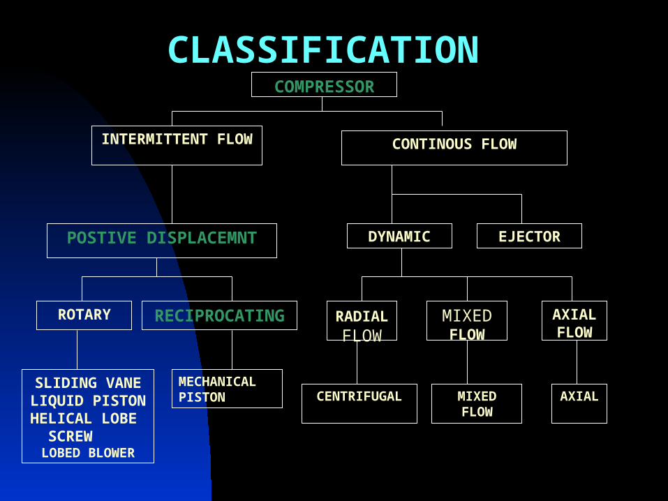
COMPRESSOR
INTERMITTENT FLOW CONTINOUS FLOW
POSTIVE DISPLACEMNT DYNAMIC EJECTOR
RECIPROCATINGROTARY
MECHANICAL PISTON
RADIAL FLOW
MIXED FLOW
AXIAL FLOW
CENTRIFUGAL MIXED FLOW
AXIAL
CLASSIFICATION
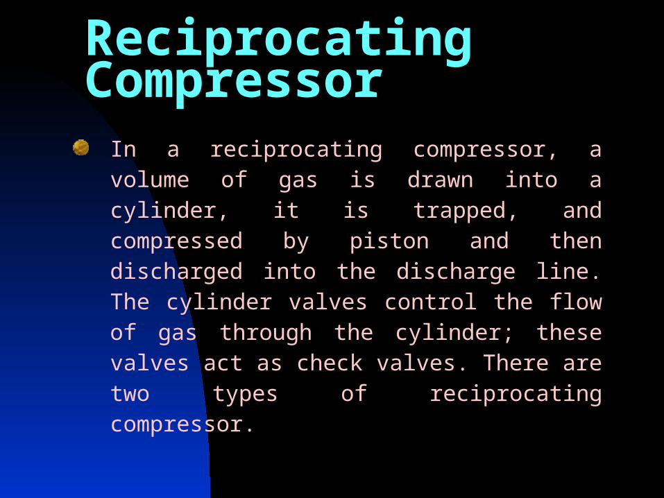
Reciprocating Compressor
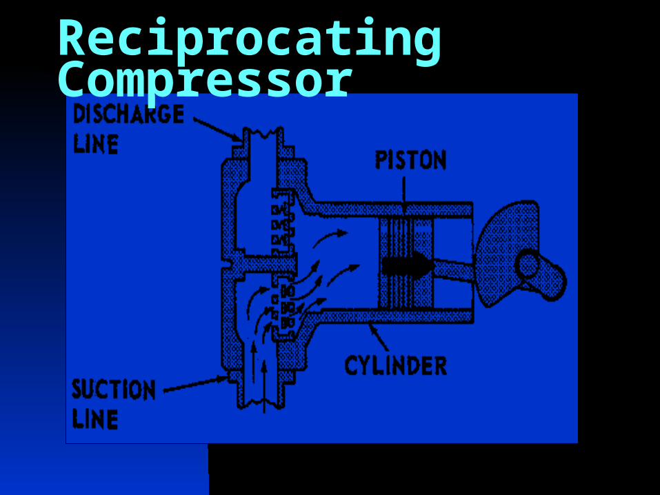
In a reciprocating compressor, a volume of gas is drawn into a cylinder, it is trapped, and compressed by piston and then discharged into the discharge line. The cylinder valves control the flow of gas through the cylinder; these valves act as check valves. There are two types of reciprocating compressor.
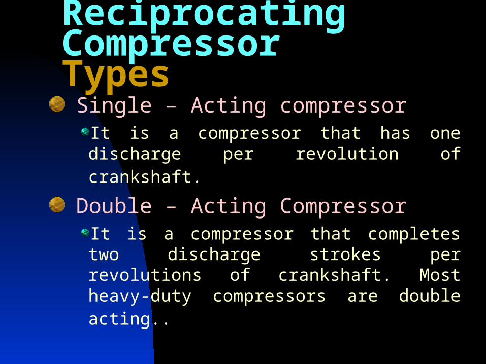
Single – Acting compressorIt is a compressor that has one discharge per revolution of crankshaft.
Double – Acting CompressorIt is a compressor that completes two discharge strokes per revolutions of crankshaft. Most heavy-duty compressors are double acting..
Reciprocating CompressorTypes
Reciprocating Compressor
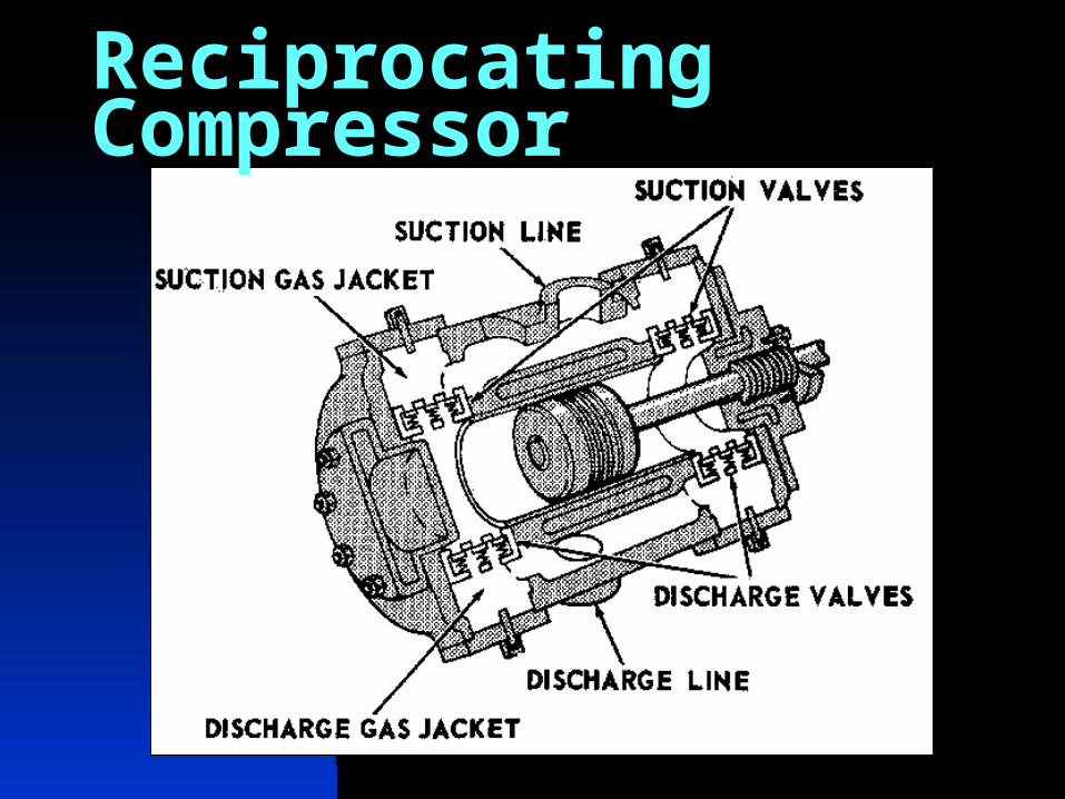
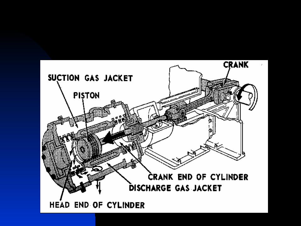
Different parts of double acting compressor are listed below.
Suction valve.
Suction gas jacket.
Piston.
Cylinder.
Discharge valve.
Discharge gas jacket
Reciprocating Compressor
Reciprocating Compressor
Construction of Reciprocating Compressors
Reciprocating compressors can be divided into two main groups.
1. Gas end.
2. Power end.
Cylinder & Liner
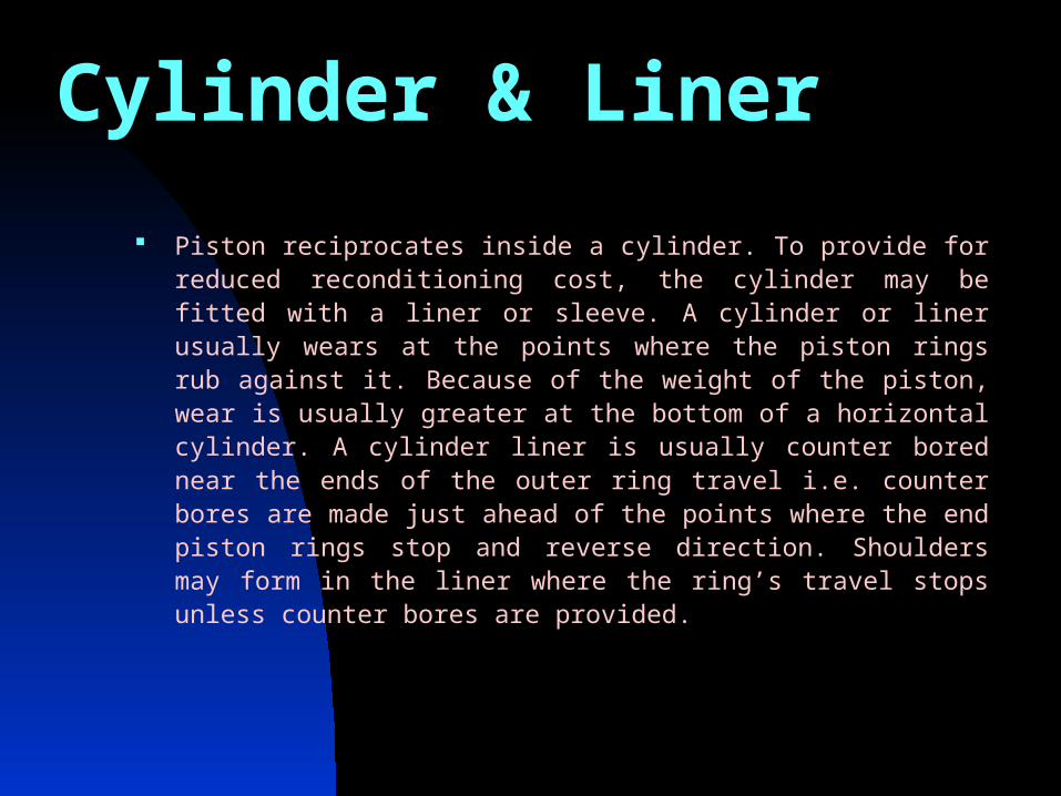
Piston reciprocates inside a cylinder. To provide for reduced reconditioning cost, the cylinder may be fitted with a liner or sleeve. A cylinder or liner usually wears at the points where the piston rings rub against it. Because of the weight of the piston, wear is usually greater at the bottom of a horizontal cylinder. A cylinder liner is usually counter bored near the ends of the outer ring travel i.e. counter bores are made just ahead of the points where the end piston rings stop and reverse direction. Shoulders may form in the liner where the ring’s travel stops unless counter bores are provided.
PistonFor low speed compressors (upto 330 rpm) and medium speed compressors (330-600 rpm), pistons are usually made of cast iron.
Upto 7” diameter cast iron pistons are made of solids. Those of more than 7” diameters are usually hollow (to reduce cost).
Carbon pistons are sometimes used for compressing oxygen and other gases that must be kept free of lubricant.
As the compressor reaches operating temperature, the piston and rod expand more than liner/cylinder does. In order to prevent seizure adequate clearance should be provided, at the same time clearance must be close enough to permit adequate support of piston rings. Similarly end clearance is also important.
A cold piston is usually installed with one third of its end clearance on the crank end and two third of its end clearance on the head end.
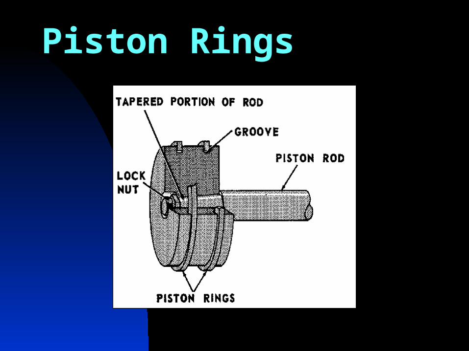
Generally, the piston rod is fastened to the piston by means of special nut that is prevented from unscrewing. The surface of the rod has suitable degree of finish designed to minimize wear on the sealing areas as much as possible. The piston is provided with grooves for piston rings and rider rings.
PISTON ROD AND PISTON
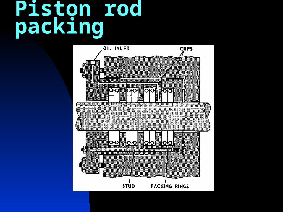
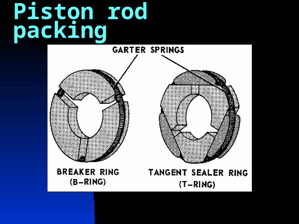
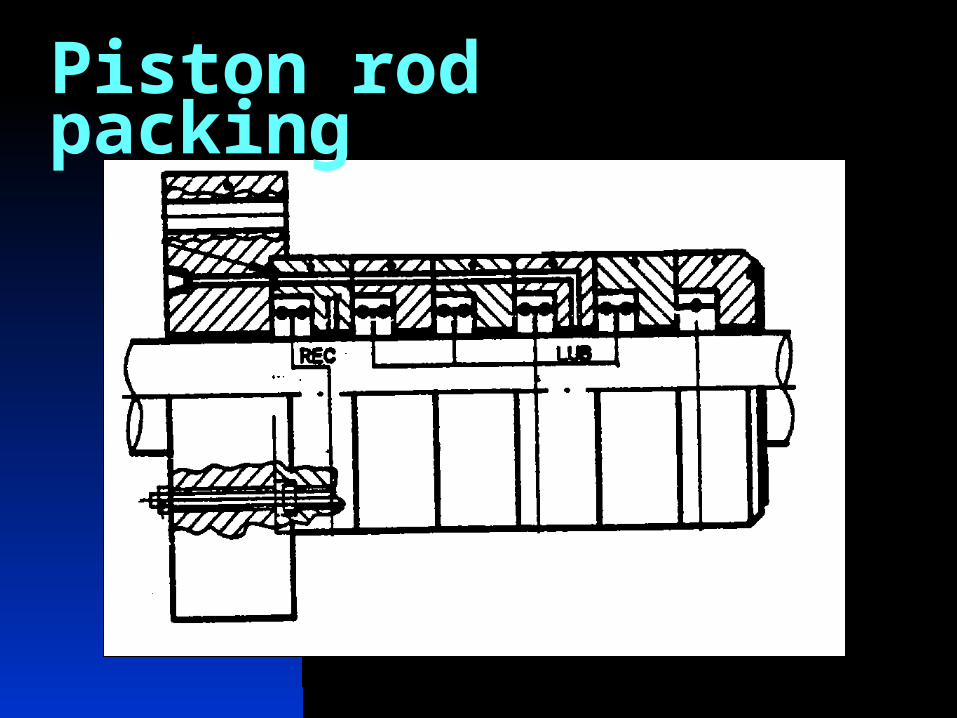
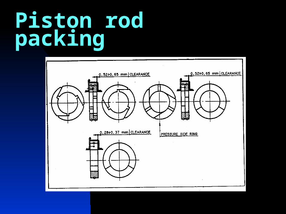
Piston rod packing ensures sealing of the compressed gas. The piston rod packing consists of series of cups each containing several seal rings side by side. The rings are built of three sectors, held together by a spring installed in the groove running around the outside of the ring.
The entire set of cups is held in place by stud bolts. Inside channels are there for cooling, gas recovery and lubrication of the piston rod packing.
Piston rod packing
Piston rod packing
Piston rod packing
Piston rod packing
Piston rod packing
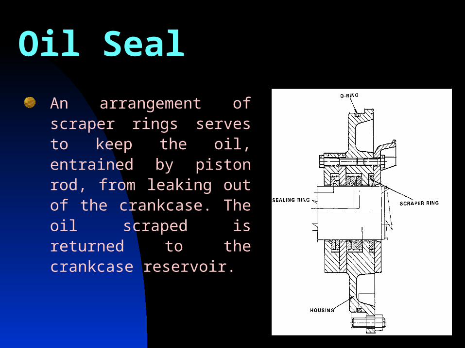
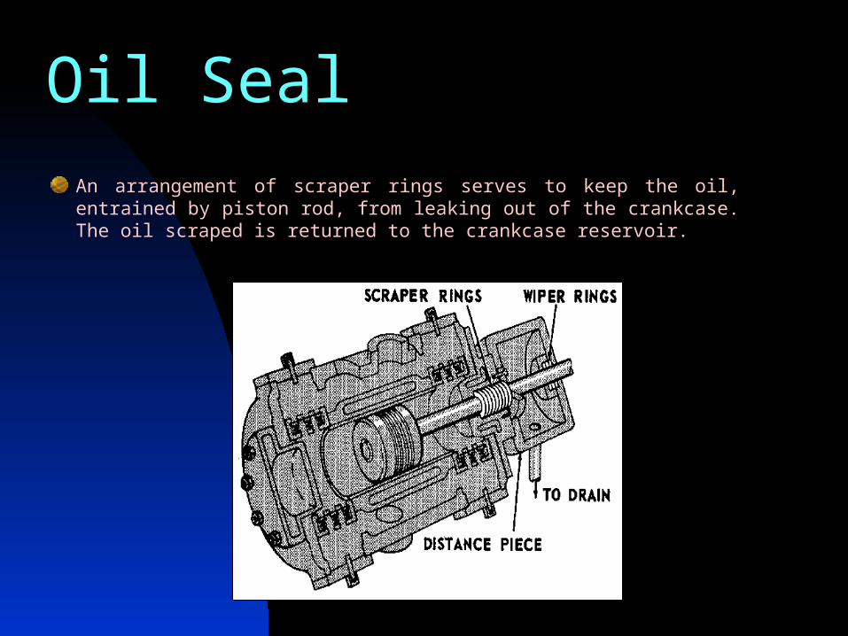
Oil Seal
An arrangement of scraper rings serves to keep the oil, entrained by piston rod, from leaking out of the crankcase. The oil scraped is returned to the crankcase reservoir.
Oil SealAn arrangement of scraper rings serves to keep the oil, entrained by piston rod, from leaking out of the crankcase. The oil scraped is returned to the crankcase reservoir.
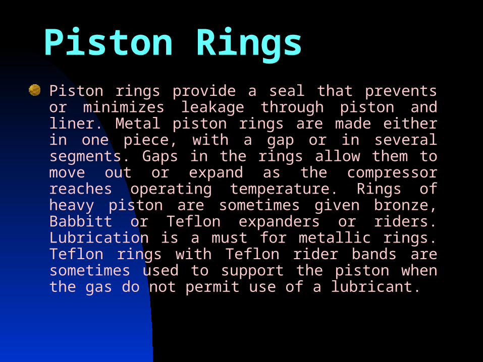
Piston RingsPiston rings provide a seal that prevents or minimizes leakage through piston and liner. Metal piston rings are made either in one piece, with a gap or in several segments. Gaps in the rings allow them to move out or expand as the compressor reaches operating temperature. Rings of heavy piston are sometimes given bronze, Babbitt or Teflon expanders or riders. Lubrication is a must for metallic rings. Teflon rings with Teflon rider bands are sometimes used to support the piston when the gas do not permit use of a lubricant.
Piston Rings
HeadThe ends of cylinder are equipped with removable heads, these heads may contain water/liquid jacket for cooling. One end is called head-end head and other crank-end head. The crank-end contains packing (a set of metallic packing rings) to prevent gas leakage around piston rod.ValvesThere are normally three types of valves, these are 1. Plate valve.2. Channel valve.3. Poppet valve.
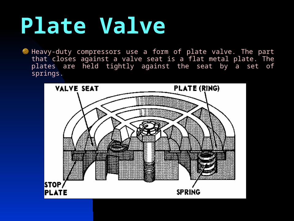
Plate ValveHeavy-duty compressors use a form of plate valve. The part that closes against a valve seat is a flat metal plate. The plates are held tightly against the seat by a set of springs.
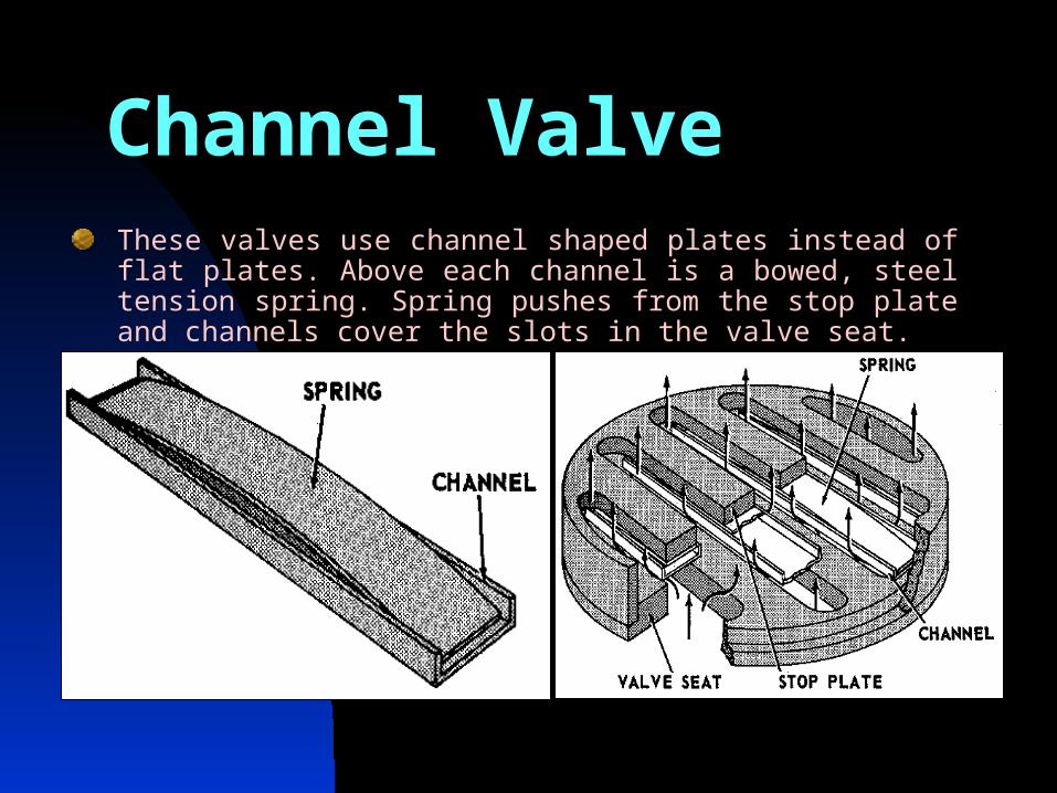
Channel ValveThese valves use channel shaped plates instead of flat plates. Above each channel is a bowed, steel tension spring. Spring pushes from the stop plate and channels cover the slots in the valve seat.
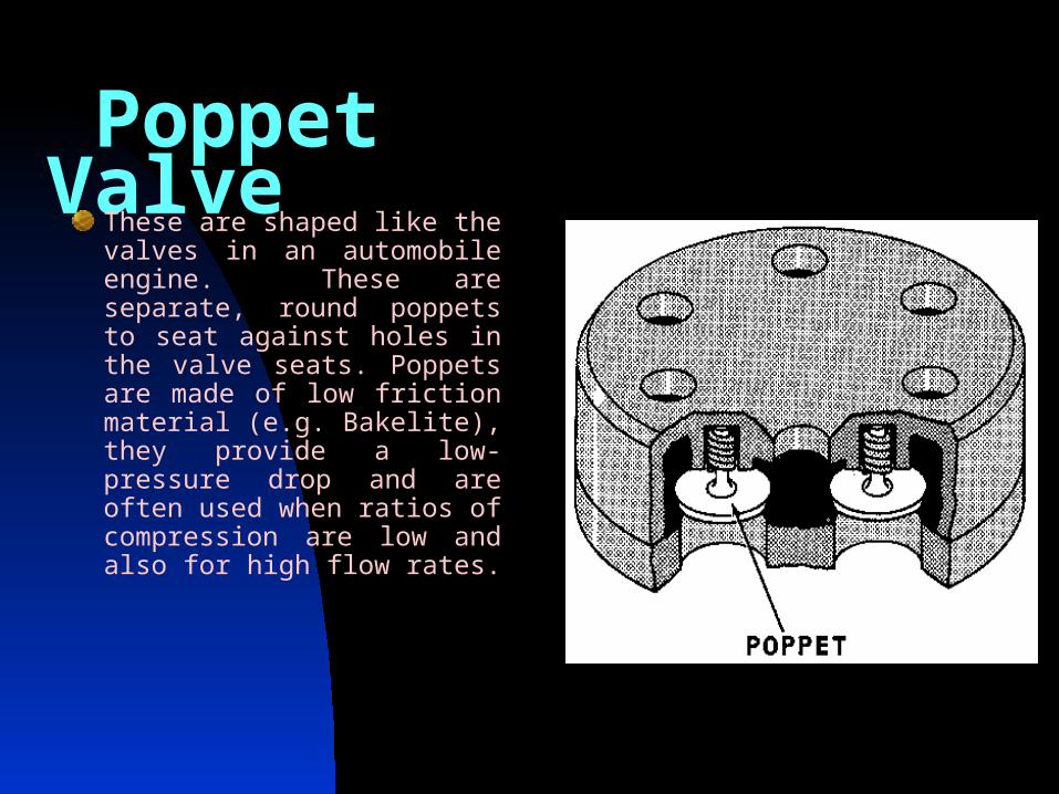
Poppet Valve These are shaped like the valves in an automobile engine. These are separate, round poppets to seat against holes in the valve seats. Poppets are made of low friction material (e.g. Bakelite), they provide a low-pressure drop and are often used when ratios of compression are low and also for high flow rates.
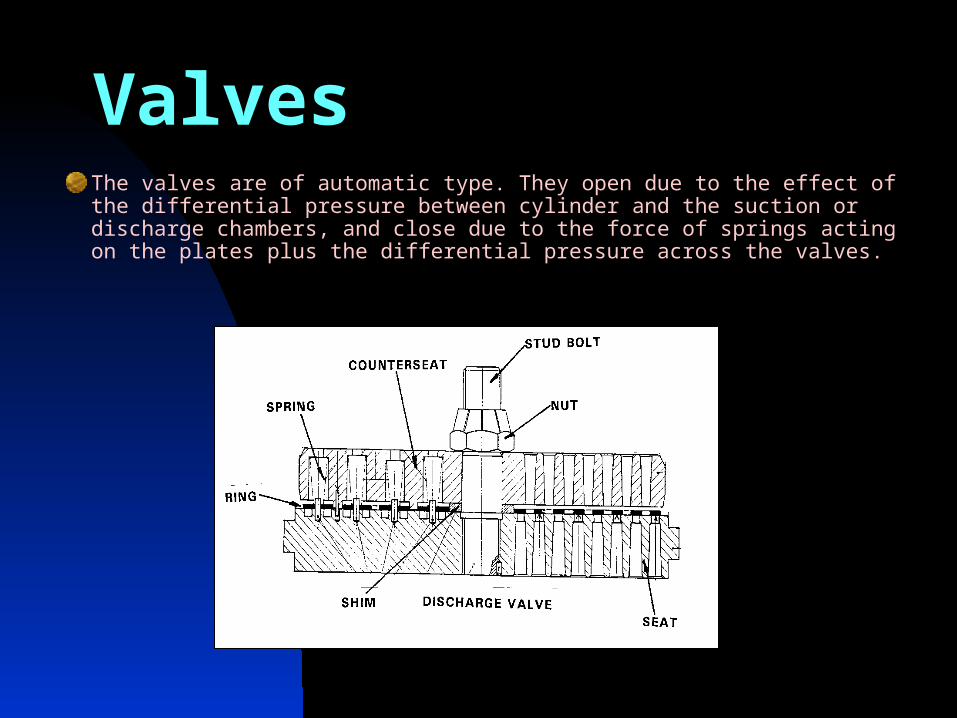
ValvesThe valves are of automatic type. They open due to the effect of the differential pressure between cylinder and the suction or discharge chambers, and close due to the force of springs acting on the plates plus the differential pressure across the valves.
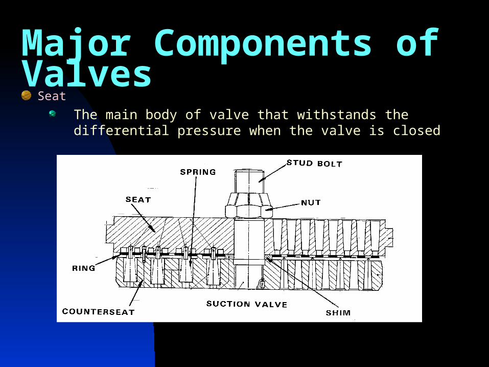
Major Components of ValvesSeat
The main body of valve that withstands the differential pressure when the valve is closed
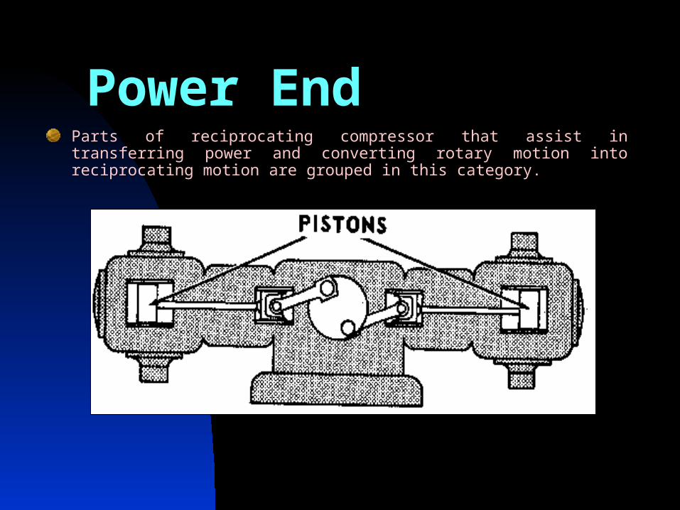
Power End Parts of reciprocating compressor that assist in transferring power and converting rotary motion into reciprocating motion are grouped in this category.
Crank Case Crank case supports the crankshaft. All bearing
supports are bored under setup condition to ensure
perfect alignment. Crankcase is provided with easy
removable covers on the top for inspection and
maintenance. The bottom of the crankcase serves
as the oil reservoir. A main pump for lubrication of
the crank mechanism is placed on the shield
mounted on the side opposite the coupling and is
driven by compressor.
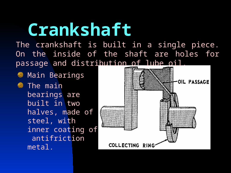
Main Bearings
The main bearings are built in two halves, made of steel, with inner coating of antifriction metal.
The crankshaft is built in a single piece. On the inside of the shaft are holes for passage and distribution of lube oil.
Crankshaft

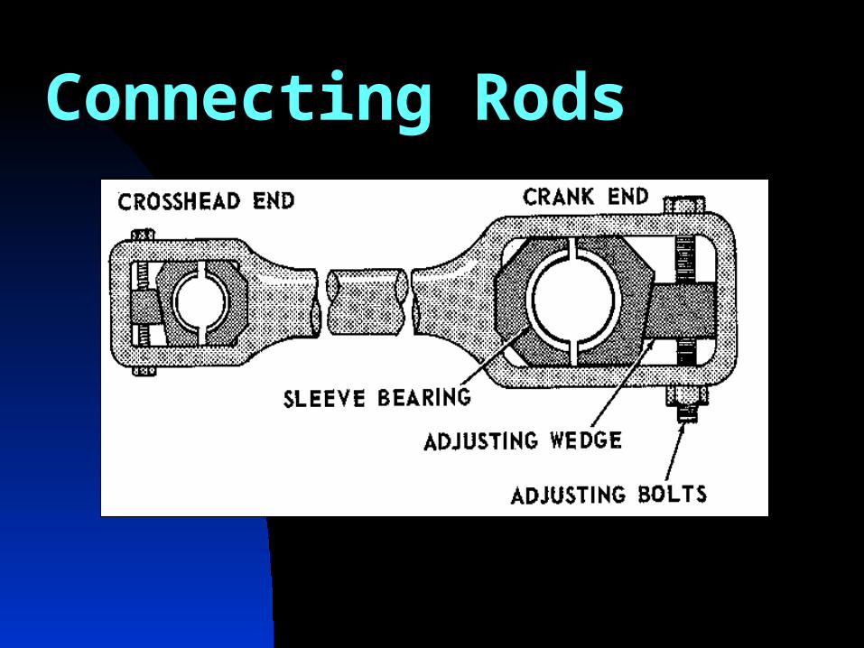
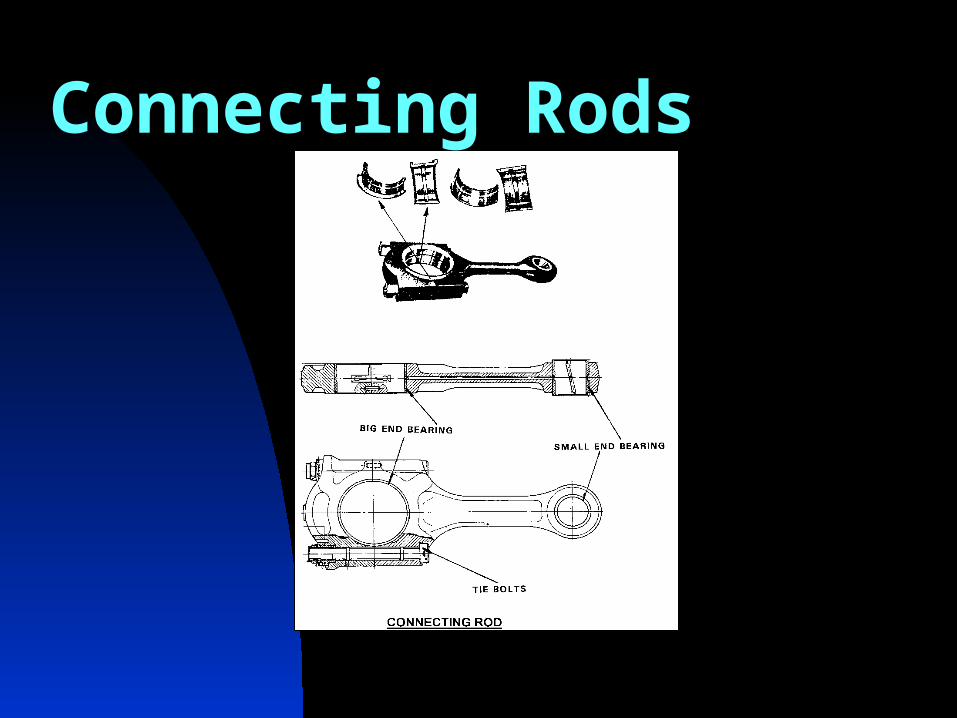
Connecting RodsThe connecting rod has two bearings. The big end bearing is built in two halves. It is made of metal with inner coating of antifriction metal. The connecting rod small end bearing is build of steel, with inner coating of antifriction metal. A hole runs through the connecting rod for it’s entire length, to allow passage of oil from the big end to the small end bush.
Connecting Rods
Connecting Rods
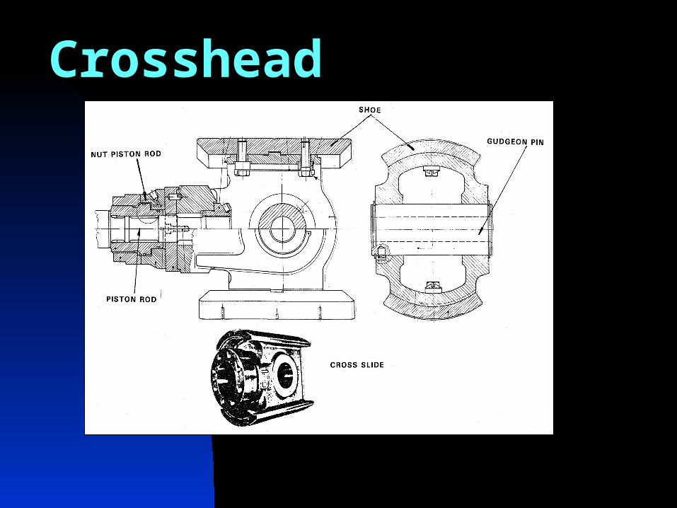
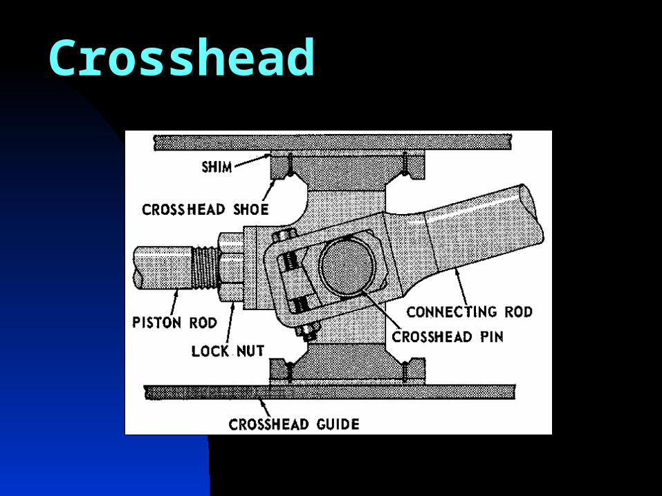
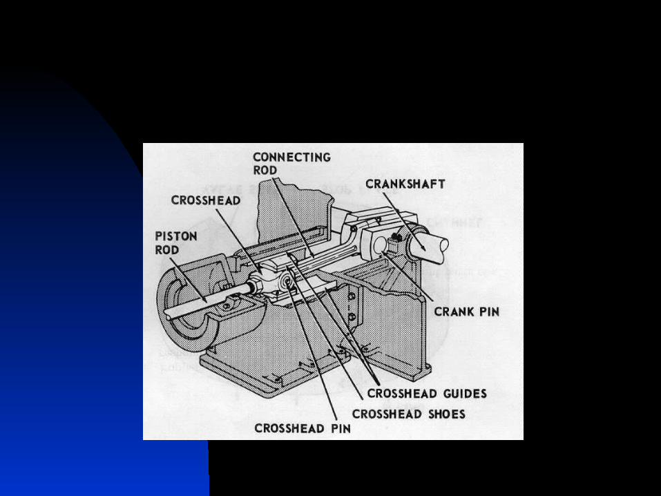
CrossheadCrosshead fastens piston rod to the connecting rod. The sliding surfaces of crosshead are coated with antifriction metal i.e. babbited shoes. These are of interchangeable type. That permits it to slide back and forth within the crosshead guides. The shoes have channels for the distribution of lube oil. The lubrication is obtained under pressure; it comes out from the two guides of the crosshead slide body. Connection between connecting rod and crosshead is realized by means of a gudgeon pin. The piston rod is connected to the crosshead by nut arrangement, tightened by means of hydraulic device.
Crosshead
Crosshead
Lubrication
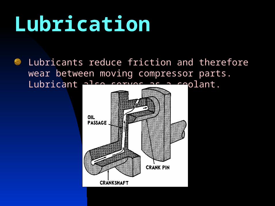
Lubricants reduce friction and therefore wear between moving compressor parts. Lubricant also serves as a coolant.
Lubrication SystemsGenerally, two types of systems are uses to lubricate the positive
displacement compressors.
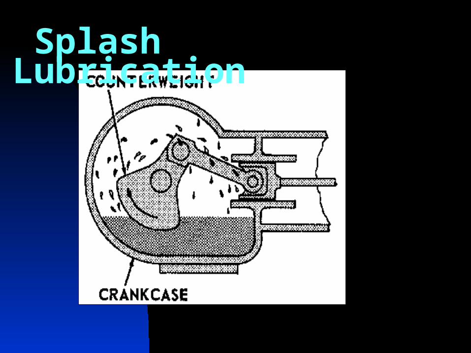
SPLASH SYSTEM
It is used in older machines. A supply is maintained in the
crankcase. Oil is splashed up by the rotation of the crank and the
counter weight into the collecting ring. Centrifugal force throws the
oil outward through an oil passage to the crank pin.
Splash Lubrication
Forced Feed System
Oil is pumped under pressure to the required parts.
Following are the main parts of system:
STRAINER
Oil from the crankcase first passes through a coarse strainer.
The strainer is removable so that chips or broken off pieces
can be cleaned out of the strainer.
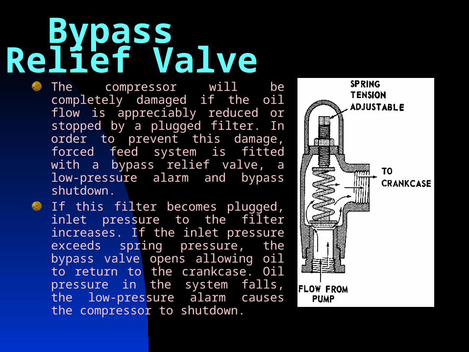
Bypass Relief ValveThe compressor will be completely damaged if the oil flow is appreciably reduced or stopped by a plugged filter. In order to prevent this damage, forced feed system is fitted with a bypass relief valve, a low-pressure alarm and bypass shutdown. If this filter becomes plugged, inlet pressure to the filter increases. If the inlet pressure exceeds spring pressure, the bypass valve opens allowing oil to return to the crankcase. Oil pressure in the system falls, the low-pressure alarm causes the compressor to shutdown.
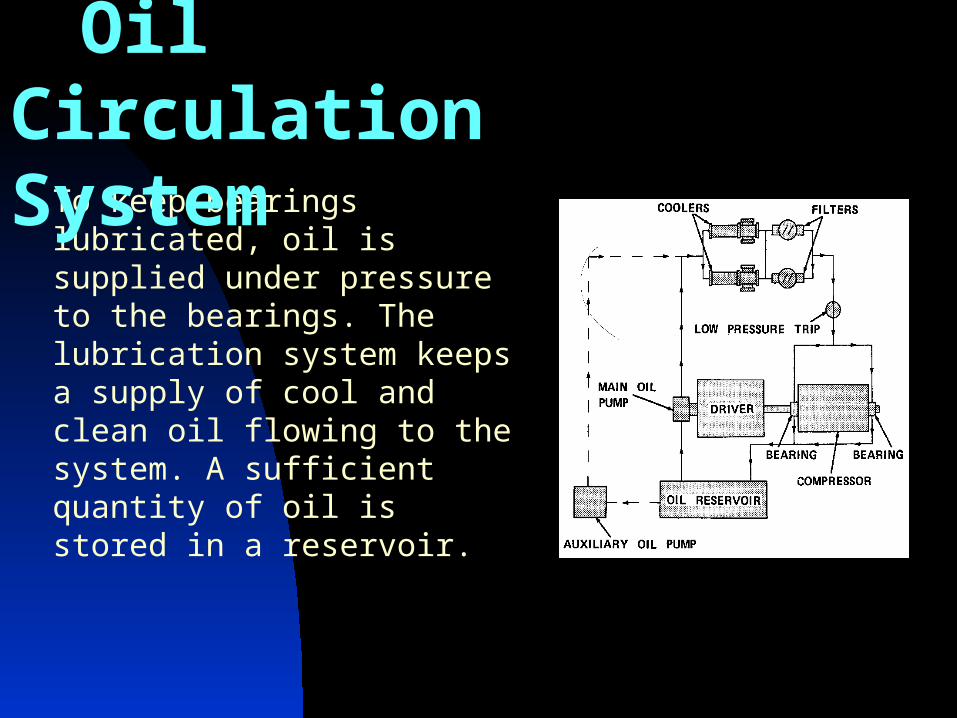
To keep bearings lubricated, oil is supplied under pressure to the bearings. The lubrication system keeps a supply of cool and clean oil flowing to the system. A sufficient quantity of oil is stored in a reservoir.
Oil Circulation System
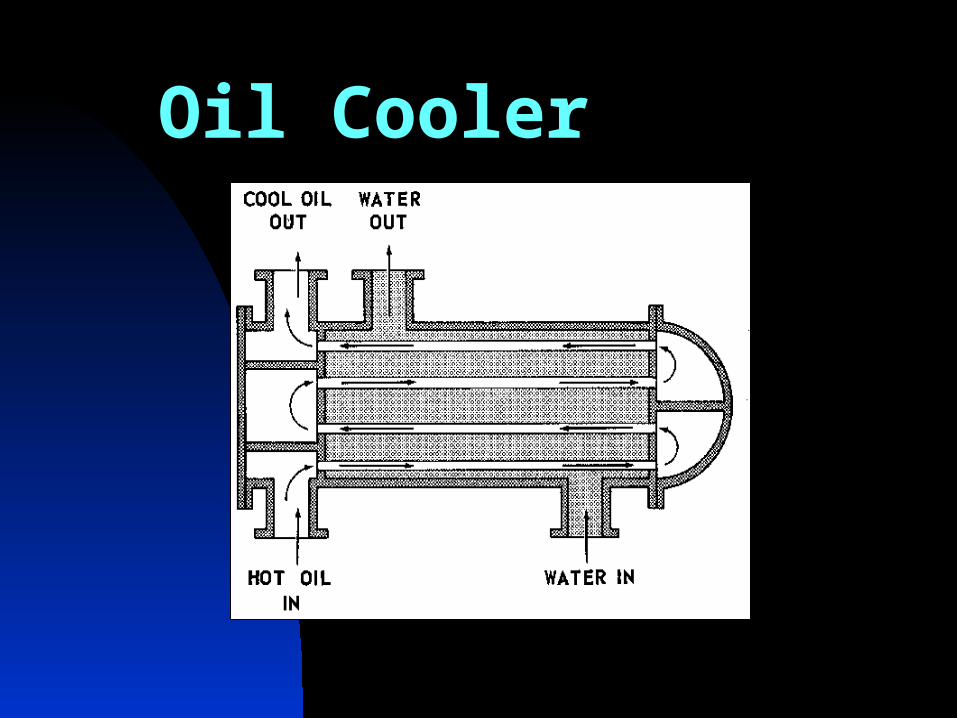
Oil CoolerOil flows from the pump to cooler. The oil in the cooler flows through the tubes. The cooling water on the shell side absorbs heat from the oil. Generally, oil temperature is kept between 40 – 50C. Oil cooler than 40C can lead to condensation of water inside the crank case. Moisture can promote sludging of oil. Temperature of oil higher than 50 C can decrease strength of bearing materials (Babbitt), that can lead to premature failure.
In order to maintain the desired temperature range, the oil system has a bypass valve upstream the cooler that is controlled by a thermostat.
Oil Cooler
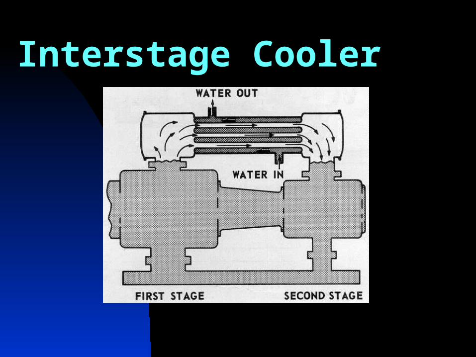
Interstage Cooler
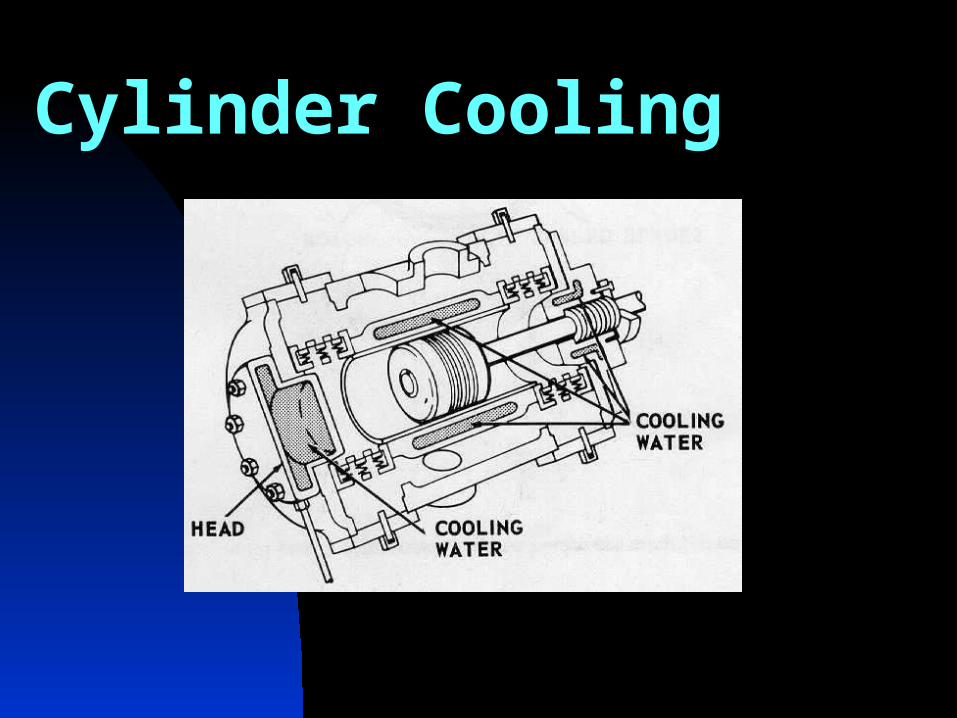
Cylinder Cooling
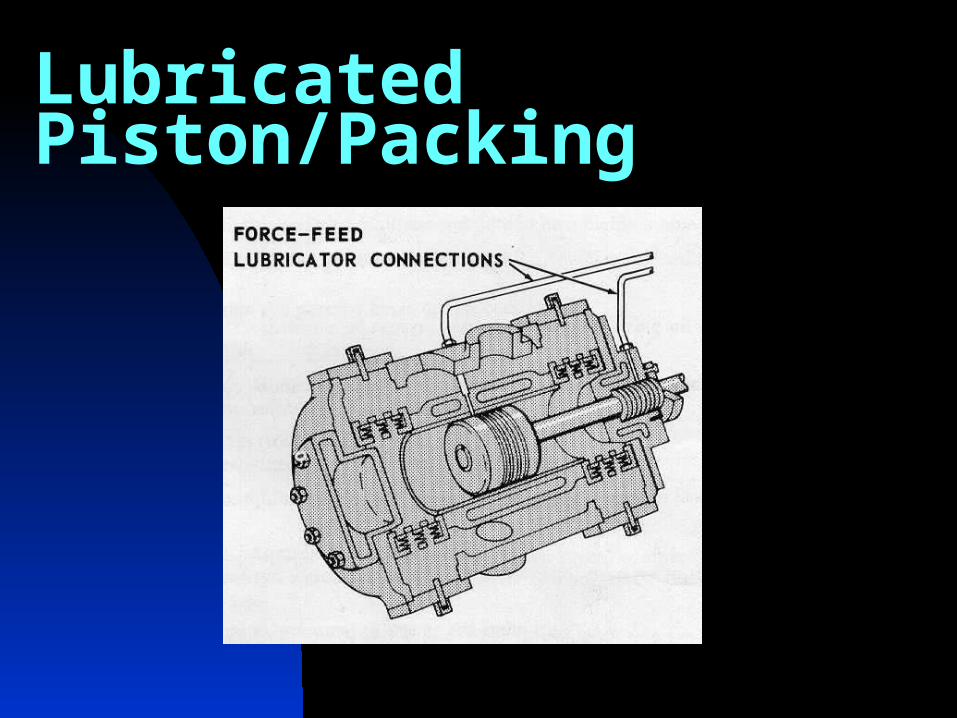
Lubricated Piston/Packing
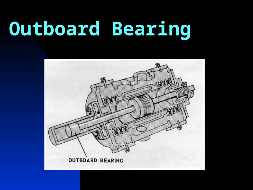
Outboard Bearing
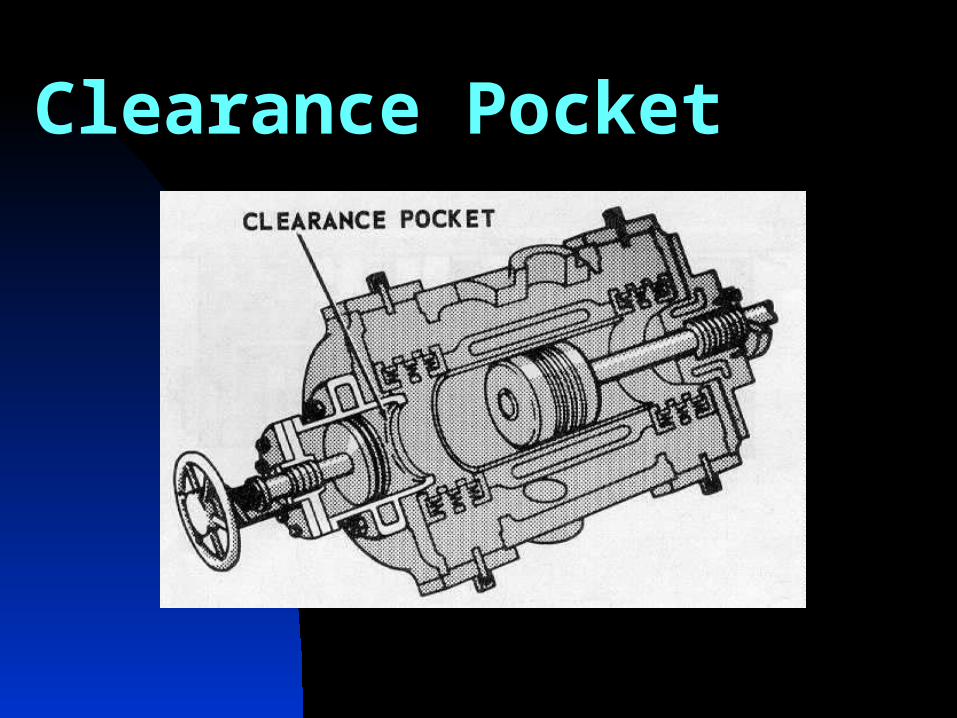
Clearance Pocket
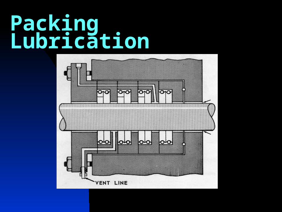
Packing Lubrication
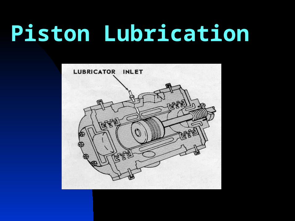
Piston Lubrication
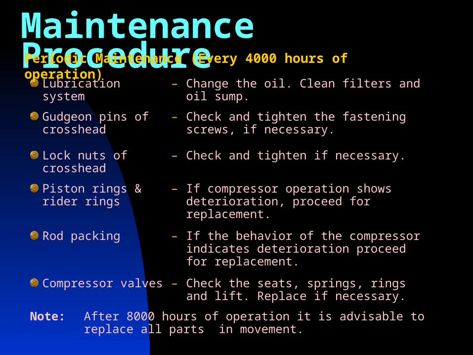
Maintenance ProcedureLubrication system – Change the oil. Clean filters and oil sump.
Gudgeon pins of crosshead
– Check and tighten the fastening screws, if necessary.
Lock nuts of crosshead – Check and tighten if necessary.
Piston rings & rider rings
– If compressor operation shows deterioration, proceed for replacement.
Rod packing – If the behavior of the compressor indicates deterioration proceed for replacement.
Compressor valves – Check the seats, springs, rings and lift. Replace if necessary.
Note: After 8000 hours of operation it is advisable to replace all parts in movement.
Periodic Maintenance (Every 4000 hours of operation)
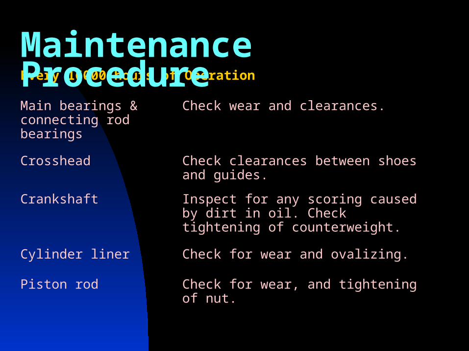
Every 16000 hours of Operation
Main bearings & connecting rod bearings
Check wear and clearances.
Crosshead Check clearances between shoes and guides.
Crankshaft Inspect for any scoring caused by dirt in oil. Check tightening of counterweight.
Cylinder liner Check for wear and ovalizing.
Piston rod Check for wear, and tightening of nut.
Maintenance Procedure
Maintenance Procedures & Safety (contd.)
After maintenance, machine shall be rotated slowly for at leas on revolution to ensure no interference.Whenever a component is disassembled. Make sure of the absence of defects before re-using. The person responsible for maintenance should ensure that all parts installed are perfectly clean.After, maintenance on cylinders and sealing rings ensure that all the lube oil pipes are filed with oil. This could be checked by loosening the pipefitting. Tighten the pipe fitting again.
Do not use a chisel to remove gaskets attached to the surface. Carefully slide a blade between gasket and surface. Damaging to the compressor-sealing surface can be avoided in this way. If the bearings are found damaged, perform thorough cleaning to avoid further damage due to contamination of oil by metallic particles.
Maintenance Procedures & Safety (contd.)
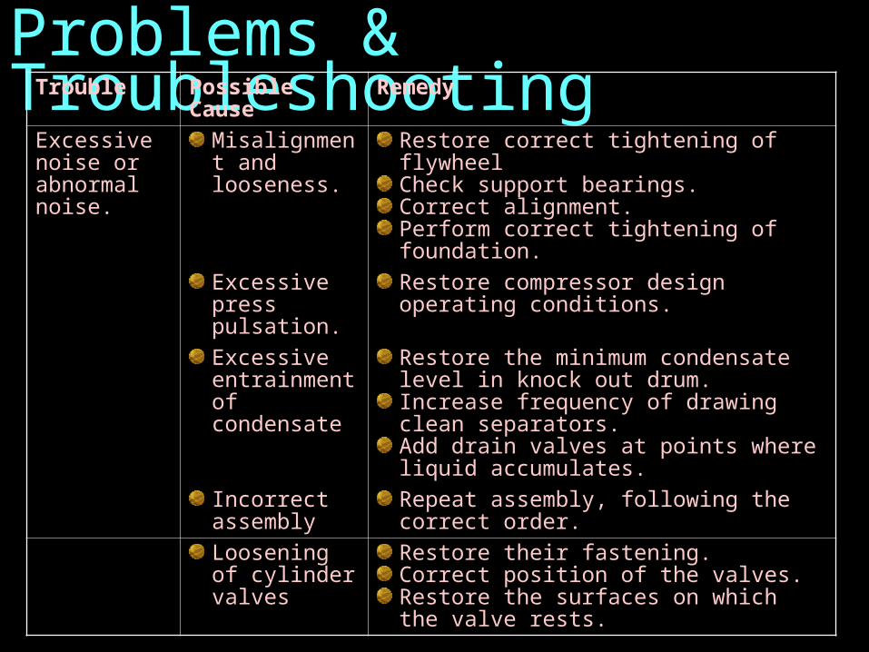
Problems & TroubleshootingTrouble Possible Cause Remedy
Excessive noise or abnormal noise.
Misalignment and looseness.
Restore correct tightening of flywheelCheck support bearings. Correct alignment. Perform correct tightening of foundation.
Excessive press pulsation.
Restore compressor design operating conditions.
Excessive entrainment of condensate
Restore the minimum condensate level in knock out drum. Increase frequency of drawing clean separators. Add drain valves at points where liquid accumulates.
Incorrect assembly
Repeat assembly, following the correct order.
Loosening of cylinder valves
Restore their fastening. Correct position of the valves. Restore the surfaces on which the valve rests.
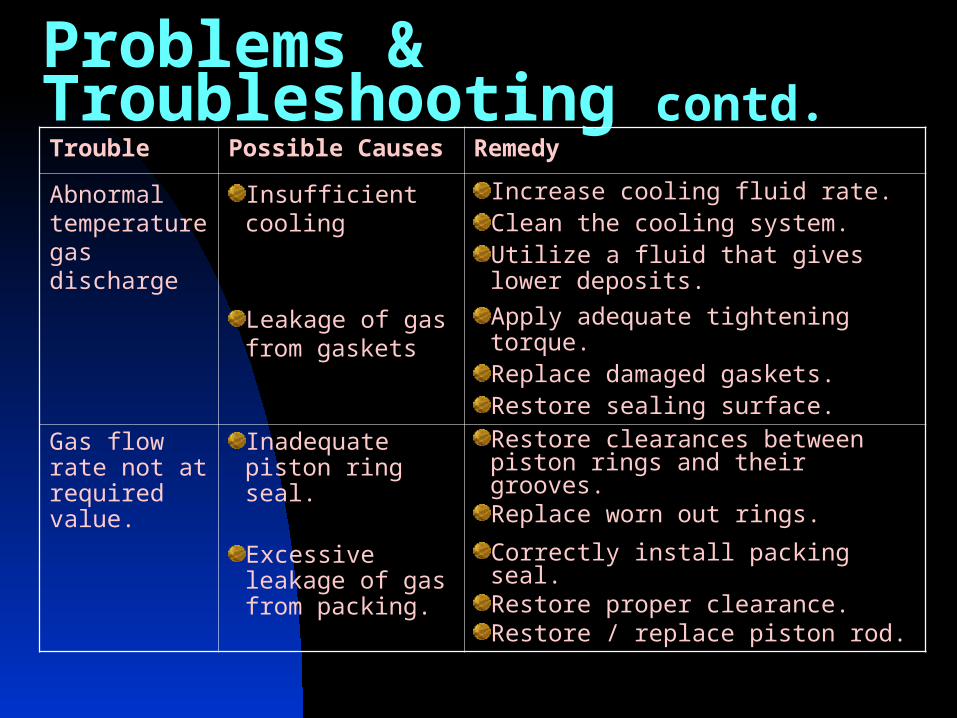
Problems & Troubleshooting contd.Trouble Possible Causes Remedy
Abnormal temperature gas discharge
Insufficient cooling Increase cooling fluid rate. Clean the cooling system. Utilize a fluid that gives lower deposits.
Leakage of gas from gaskets
Apply adequate tightening torque. Replace damaged gaskets. Restore sealing surface.
Gas flow rate not at required value.
Inadequate piston ring seal.
Restore clearances between piston rings and their grooves. Replace worn out rings.
Excessive leakage of gas from packing.
Correctly install packing seal. Restore proper clearance. Restore / replace piston rod.


![Reciprocating Compressor M II SERIES...Reciprocating Compressor [Single Stage, Open Type] M II SERIES * Some optional items are included in this photo. High Performance Derived from](https://img.dokumen.tips/doc/110x75/5f71d371bec994147c3b2337/reciprocating-compressor-m-ii-series-reciprocating-compressor-single-stage.jpg)