Embed Size (px)
DESCRIPTION
Recent TOB Developments. C. Campagnari On behalf of the US module testing groups. Outline. Status Update 4 Hybrid Thermal Cycler Stereo and 6 chip module production Dead pipeline column fault Module Burn-in (Wien Cold Box) Status Grounding improvements Backplane pulsing First US Rod - PowerPoint PPT Presentation
Citation preview

Recent TOB Developments
C. CampagnariOn behalf of the US module testing groups
TOB status update to Module Testing Group October 21, 2003 – Campagnari 2
Outline
• Status Update– 4 Hybrid Thermal Cycler– Stereo and 6 chip module production
• Dead pipeline column fault– Module Burn-in (Wien Cold Box) Status
• Grounding improvements• Backplane pulsing
– First US Rod
• CMN (Micro-discharge) Problem– Description of problem– Why you should be concerned about it?– Studies performed– Future plans/Request for aid
TOB status update to Module Testing Group October 21, 2003 – Campagnari 3
Hybrid Thermal Cycler-Pulser
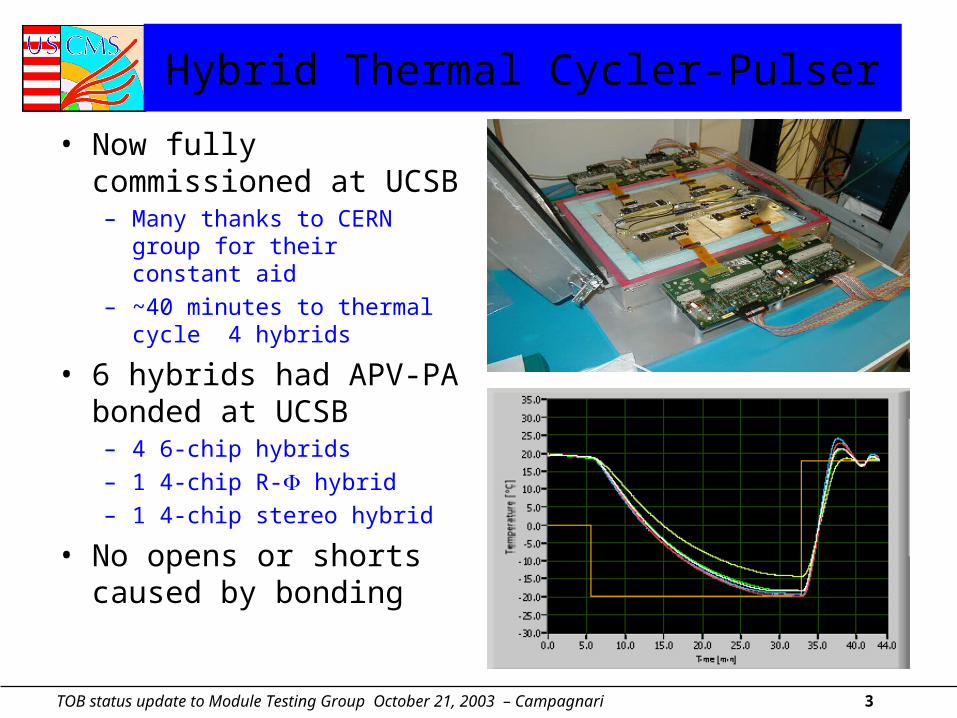
• Now fully commissioned at UCSB– Many thanks to CERN group
for their constant aid
– ~40 minutes to thermal cycle 4 hybrids
• 6 hybrids had APV-PA bonded at UCSB – 4 6-chip hybrids
– 1 4-chip R- hybrid
– 1 4-chip stereo hybrid
• No opens or shorts caused by bonding
TOB status update to Module Testing Group October 21, 2003 – Campagnari 4
Hybrid Thermal Cycler at UCSB (2)
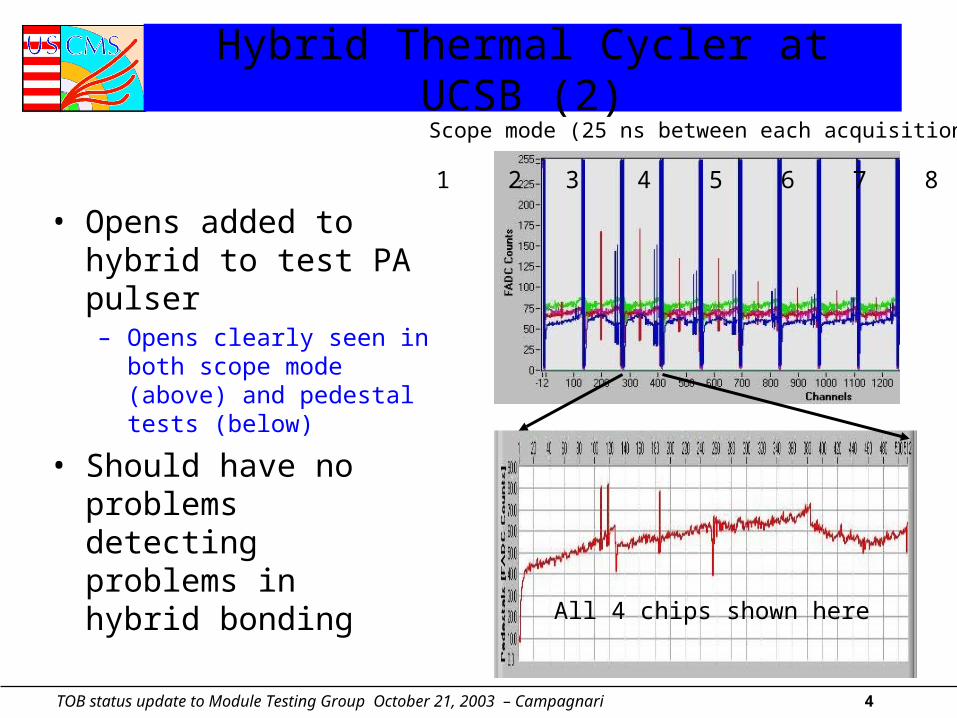
• Opens added to hybrid to test PA pulser– Opens clearly seen in both
scope mode (above) and pedestal tests (below)
• Should have no problems detecting problems in hybrid bonding
All 4 chips shown here
Scope mode (25 ns between each acquisition)
1 2 3 4 5 6 7 8 9
TOB status update to Module Testing Group October 21, 2003 – Campagnari 5
Modules Produced with Final Hybrids
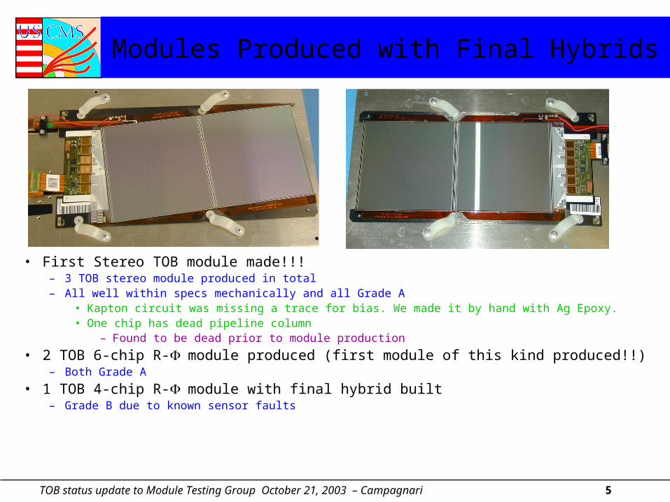
• First Stereo TOB module made!!!– 3 TOB stereo module produced in total– All well within specs mechanically and all Grade A
• Kapton circuit was missing a trace for bias. We made it by hand with Ag Epoxy. • One chip has dead pipeline column
– Found to be dead prior to module production
• 2 TOB 6-chip R-module produced (first module of this kind produced!!)– Both Grade A
• 1 TOB 4-chip R-module with final hybrid built– Grade B due to known sensor faults
TOB status update to Module Testing Group October 21, 2003 – Campagnari 6
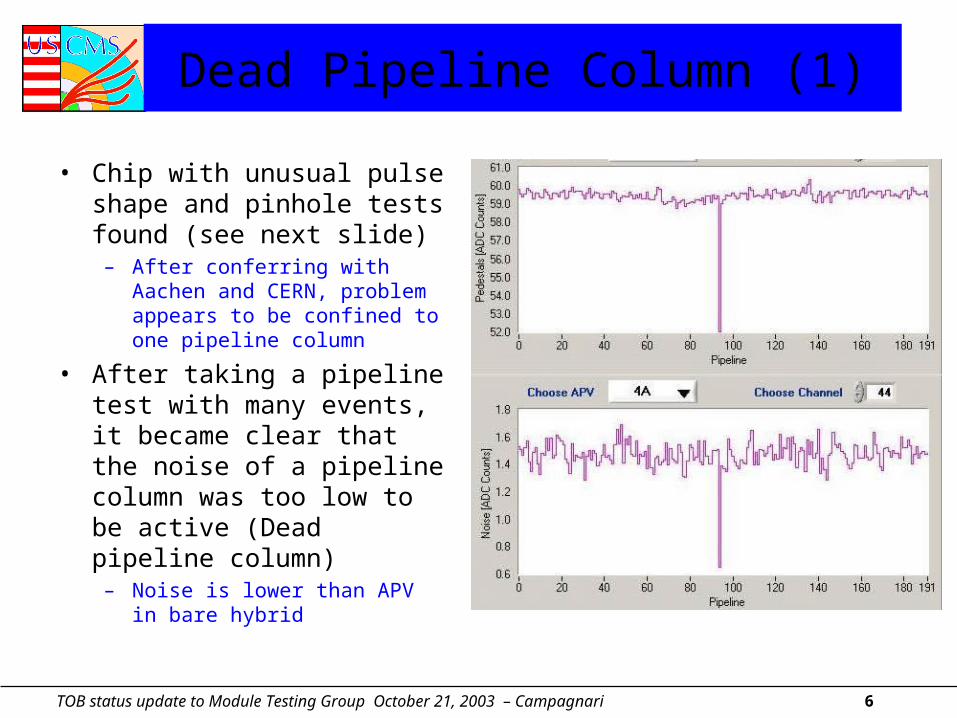
Dead Pipeline Column (1)
• Chip with unusual pulse shape and pinhole tests found (see next slide)
– After conferring with Aachen and CERN, problem appears to be confined to one pipeline column
• After taking a pipeline test with many events, it became clear that the noise of a pipeline column was too low to be active (Dead pipeline column)
– Noise is lower than APV in bare hybrid
TOB status update to Module Testing Group October 21, 2003 – Campagnari 7
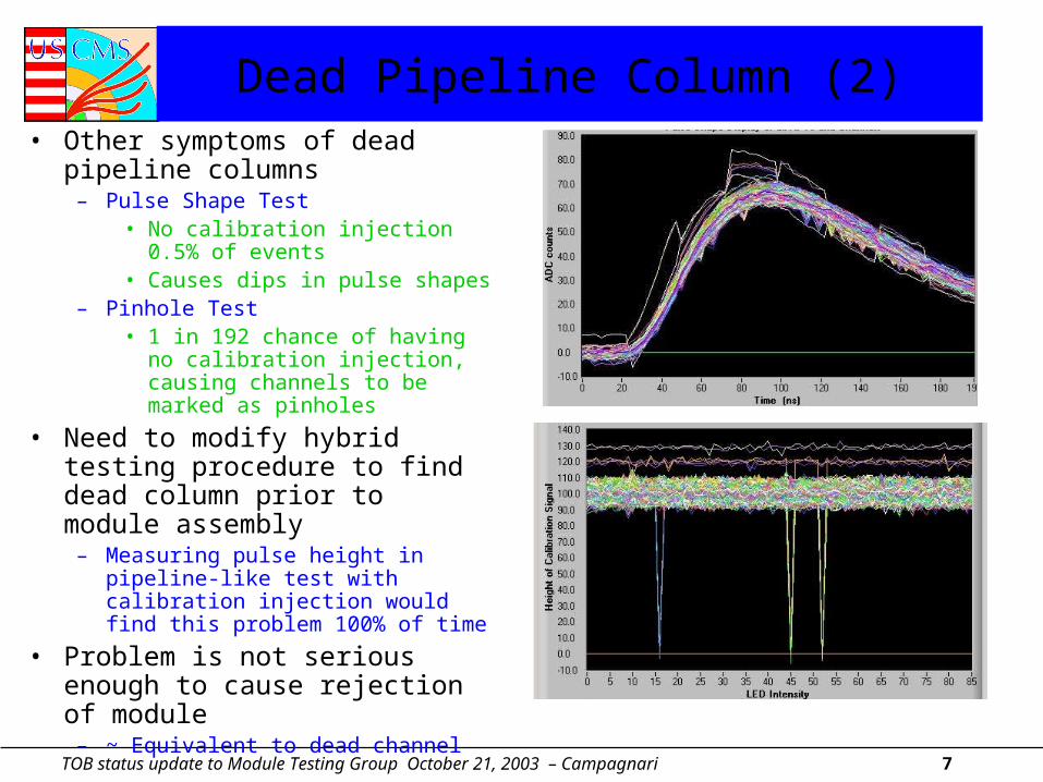
Dead Pipeline Column (2)• Other symptoms of dead pipeline
columns– Pulse Shape Test
• No calibration injection 0.5% of events
• Causes dips in pulse shapes– Pinhole Test
• 1 in 192 chance of having no calibration injection, causing channels to be marked as pinholes
• Need to modify hybrid testing procedure to find dead column prior to module assembly
– Measuring pulse height in pipeline-like test with calibration injection would find this problem 100% of time
• Problem is not serious enough to cause rejection of module
– ~ Equivalent to dead channel
TOB status update to Module Testing Group October 21, 2003 – Campagnari 8
Module Cold Box Status
• All functionalities demonstrated (UCR/UCSB)– Cold box fully instrumented
• 10 UTRI, 10 PAACB, FED multiplexer, 2nd CCU and electrometers
– Works with multiplexer, electrometers and PAACBs – Performed long term module tests during production run with full
readout of temperatures and currents
• Since September CMS week– Implemented grounding scheme to reduce noise greatly with
multiple modules– Conducted first backplane pulse tests
TOB status update to Module Testing Group October 21, 2003 – Campagnari 9
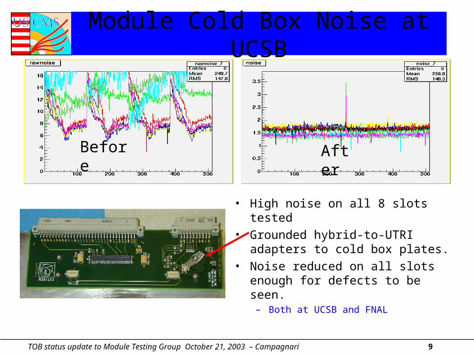
Module Cold Box Noise at UCSB
• High noise on all 8 slots tested• Grounded hybrid-to-UTRI adapters
to cold box plates.• Noise reduced on all slots enough
for defects to be seen.– Both at UCSB and FNAL
Before After
TOB status update to Module Testing Group October 21, 2003 – Campagnari 10
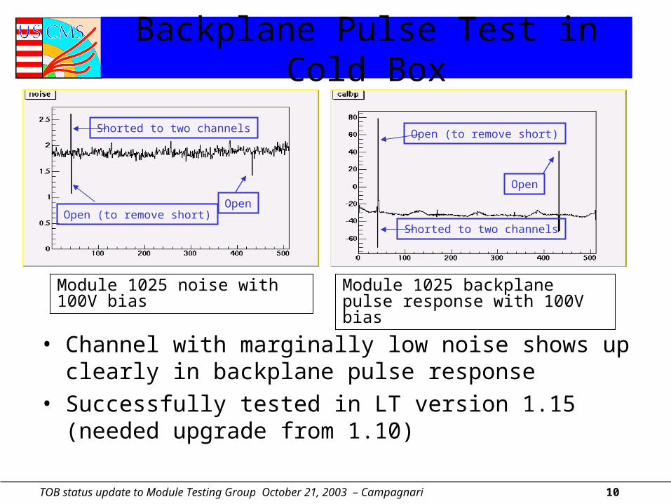
Backplane Pulse Test in Cold Box
• Channel with marginally low noise shows up clearly in backplane pulse response
• Successfully tested in LT version 1.15 (needed upgrade from 1.10)
Module 1025 noise with 100V bias Module 1025 backplane pulse response with 100V bias
OpenOpen (to remove short)
Shorted to two channels
Shorted to two channels
Open
Open (to remove short)
TOB status update to Module Testing Group October 21, 2003 – Campagnari 11
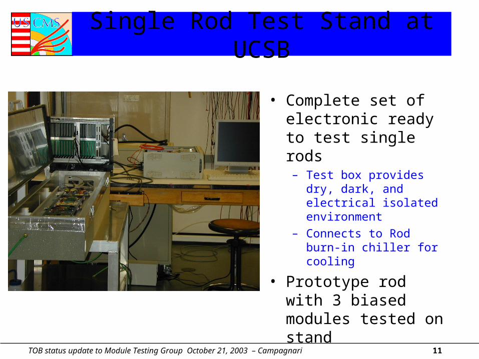
Single Rod Test Stand at UCSB
• Complete set of electronic ready to test single rods– Test box provides dry,
dark, and electrical isolated environment
– Connects to Rod burn-in chiller for cooling
• Prototype rod with 3 biased modules tested on stand
TOB status update to Module Testing Group October 21, 2003 – Campagnari 12
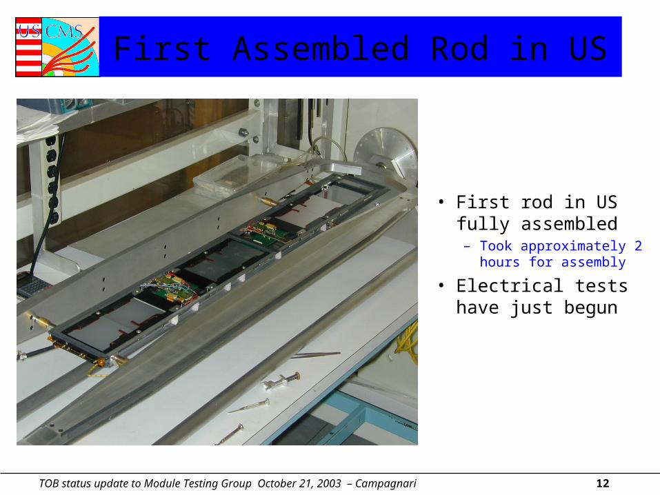
First Assembled Rod in US
• First rod in US fully assembled– Took approximately
2 hours for assembly
• Electrical tests have just begun
TOB status update to Module Testing Group October 21, 2003 – Campagnari 13
CMN Problem
• 14 of 60 modules produced at UCSB exhibit large common mode noise (one chip only)
• All of the 14 modules have a larger bias current than expected from sensor QTC probing– Extremely high noise on 1-4 channels on each module suggests
all the excess current localized to these channels– No obvious damage seen on these channels (visual inspection)– No indication of problems seen in sensor QTC measurements
• At UCSB, problem always appeared at first test after bonding– 1 module at FNAL developed problem during Wien box module
burn-in after a full ARCS module characterization
TOB status update to Module Testing Group October 21, 2003 – Campagnari 14
Why be concerned about CMN problem?
• One can argue that this may not be a real problem for several reasons:
1. It is mainly occurring at high bias voltages2. It causes only a small amount of Common Mode Noise (CMN) 3. The noise is removed by CMN subtraction in the FED.
– In fact we see evidence that all of the above are not quite right: (see discussion below)
– It may be that more sophisticated CMN removal algorithms are needed and hopefully the FED is capable of running them
– It may be that the new ST sensors have a drastic reduction in this problem– Study of 102 recently produced ST sensors sent to the US (thanks
Manfred et al.) gives indication that problem is less severe in new production
– In addition, CMN problem developed in 1 FNAL module during burn-in
– Not clear how the problem will develop during operation
TOB status update to Module Testing Group October 21, 2003 – Campagnari 15
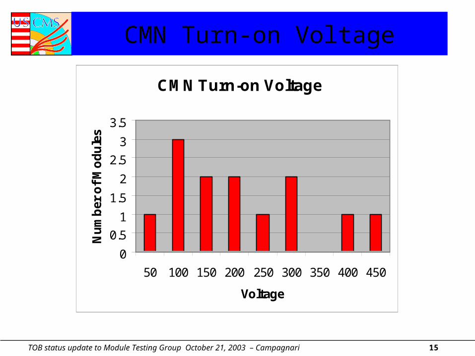
CMN Turn-on Voltage
CMN Turn-on Voltage
0
0.5
1
1.5
2
2.5
3
3.5
50 100 150 200 250 300 350 400 450
Voltage
Nu
mb
er o
f M
od
ule
s
TOB status update to Module Testing Group October 21, 2003 – Campagnari 16
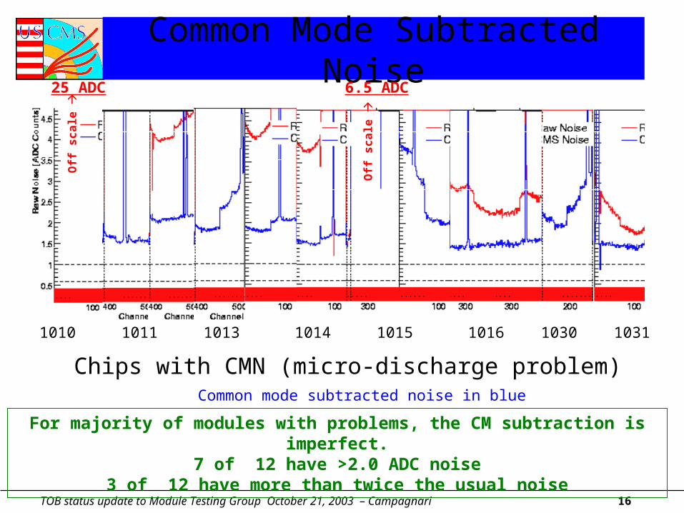
Common Mode Subtracted Noise25 ADC
Module #: 869 881 1010 1011 1013 1014 1015 1016 1030 1031 1038 1042
6.5 ADC
Chips with CMN (micro-discharge problem)Common mode subtracted noise in blue
For majority of modules with problems, the CM subtraction is imperfect.7 of 12 have >2.0 ADC noise
3 of 12 have more than twice the usual noise
Off
sc
ale
Off
sc
ale
TOB status update to Module Testing Group October 21, 2003 – Campagnari 17
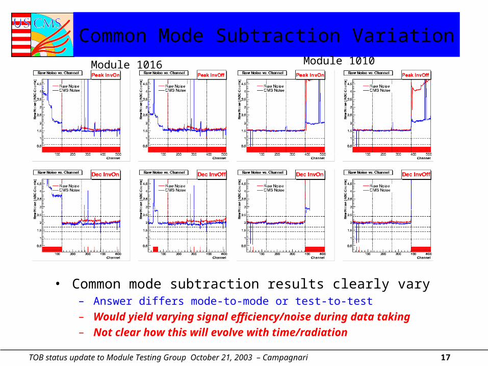
Common Mode Subtraction Variation
• Common mode subtraction results clearly vary– Answer differs mode-to-mode or test-to-test– Would yield varying signal efficiency/noise during data taking– Not clear how this will evolve with time/radiation
Module 1016 Module 1010
TOB status update to Module Testing Group October 21, 2003 – Campagnari 18
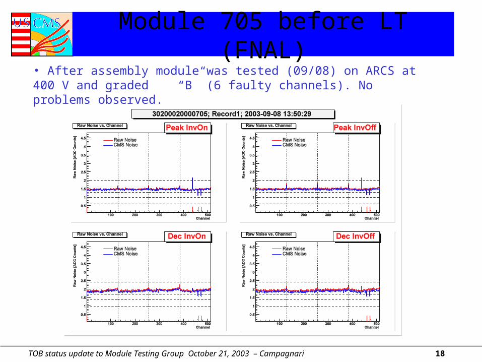
Module 705 before LT (FNAL)• After assembly module was tested (09/08) on ARCS at 400 V and graded “B” (6 faulty channels). No problems observed.
TOB status update to Module Testing Group October 21, 2003 – Campagnari 19
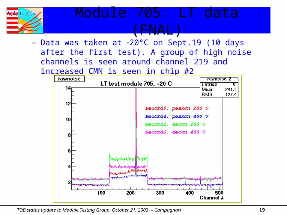
Module 705: LT data (FNAL)– Data was taken at 20°C on Sept.19 (10 days after the first test).
A group of high noise channels is seen around channel 219 and increased CMN is seen in chip #2
TOB status update to Module Testing Group October 21, 2003 – Campagnari 20
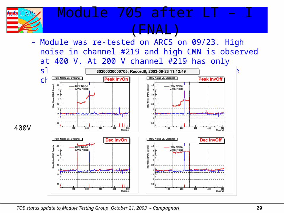
Module 705 after LT – I (FNAL)– Module was re-tested on ARCS on 09/23. High noise in channel
#219 and high CMN is observed at 400 V. At 200 V channel #219 has only slightly higher noise than the rest of the channels
400V
TOB status update to Module Testing Group October 21, 2003 – Campagnari 21
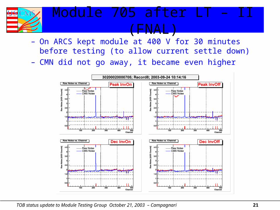
Module 705 after LT – II (FNAL)– On ARCS kept module at 400 V for 30 minutes before testing (to
allow current settle down)– CMN did not go away, it became even higher
TOB status update to Module Testing Group October 21, 2003 – Campagnari 22
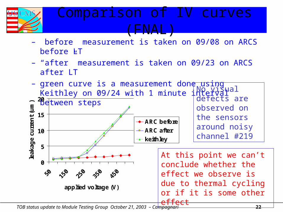
Comparison of IV curves (FNAL) – ”before” measurement is taken on 09/08 on ARCS before LT– “after” measurement is taken on 09/23 on ARCS after LT– green curve is a measurement done using Keithley on 09/24
with 1 minute interval between steps
0
5
10
15
20
50 150
250
350
450
applied voltage (V)
leak
age
curr
ent
(um
)
ARC before
ARC after
keithley
No visual defects are observed on the sensors around noisy channel #219
At this point we can’t conclude whether the effect we observe is due to thermal cycling or if it is some other effect
TOB status update to Module Testing Group October 21, 2003 – Campagnari 23
Studies to determine origin of CMN problem
• 3 FNAL CMN problem modules sent to Karlsruhe for irradiation studies– See talk by F. Hartmann
• Extensive program of sensor probing and additional module IV measurement undertaken– Sensors probed prior to assembly in modules
• Sensors with >5 A extra current relative to sensor QTC measurement separated from others
– Module then assembled and bias bonded to first sensor• IV measured
– Bias is bonded to second sensor• IV remeasured
– Module is then fully bonded and tested
TOB status update to Module Testing Group October 21, 2003 – Campagnari 24
Sensor Probing
• Three Sets of Sensors Probed– Old OB2 (Week 47 2001 to Week 21 2002)
• 75 Sensors– Old OB1 (Week 43 2001 to Week 2 2002)
• 31 Sensors– New OB2 (Week 38-41 2002)
• 97 Sensors
• Environmental conditions tightly controlled– Temperature 23.1-23.8 C– RH < 30% at all times
TOB status update to Module Testing Group October 21, 2003 – Campagnari 25
Results of Probing Study - UCSB (1)
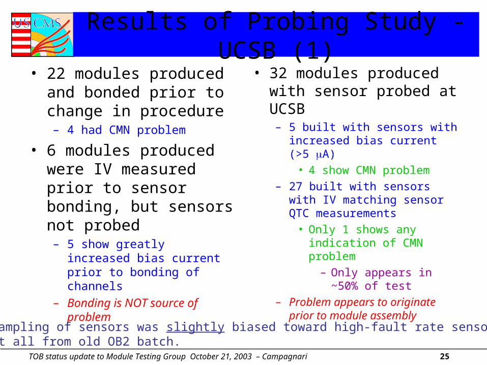
• 22 modules produced and bonded prior to change in procedure– 4 had CMN problem
• 6 modules produced were IV measured prior to sensor bonding, but sensors not probed– 5 show greatly increased bias
current prior to bonding of channels
– Bonding is NOT source of problem
• 32 modules produced with sensor probed at UCSB– 5 built with sensors with
increased bias current (>5 A)
• 4 show CMN problem
– 27 built with sensors with IV matching sensor QTC measurements
• Only 1 shows any indication of CMN problem
– Only appears in ~50% of test
– Problem appears to originate prior to module assembly
The sampling of sensors was slightly biased toward high-fault rate sensors.Almost all from old OB2 batch.
TOB status update to Module Testing Group October 21, 2003 – Campagnari 26
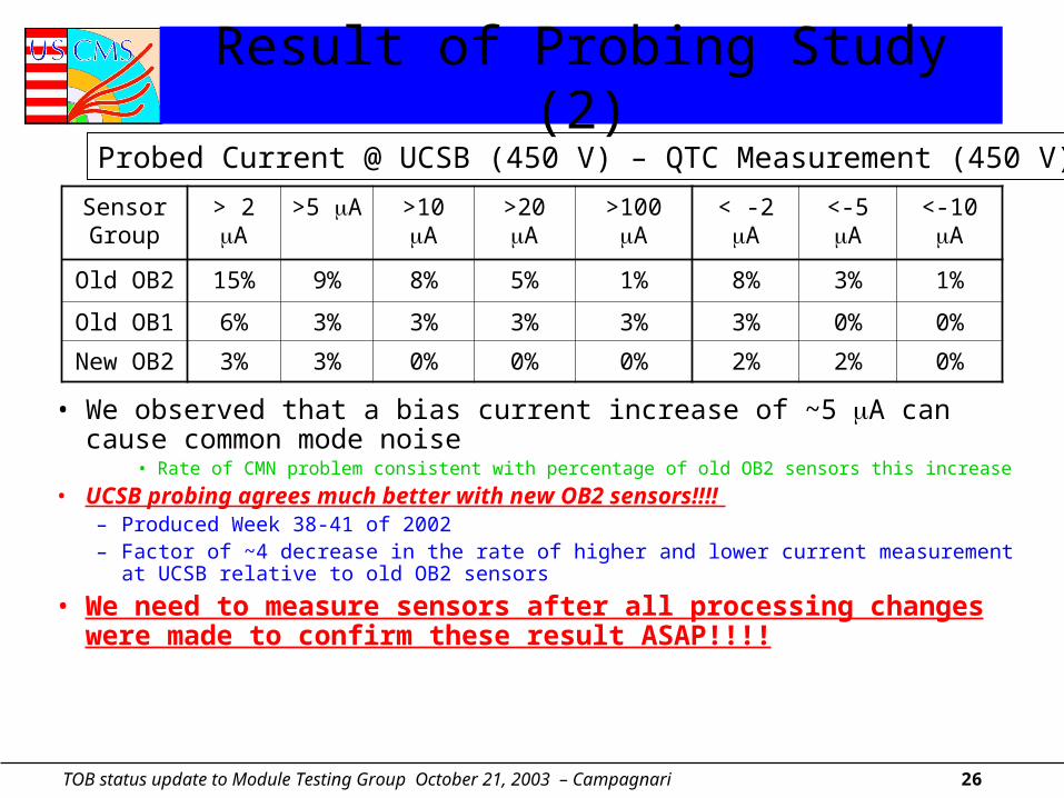
Result of Probing Study (2)
• We observed that a bias current increase of ~5 A can cause common mode noise
• Rate of CMN problem consistent with percentage of old OB2 sensors this increase
• UCSB probing agrees much better with new OB2 sensors!!!! – Produced Week 38-41 of 2002– Factor of ~4 decrease in the rate of higher and lower current measurement at UCSB
relative to old OB2 sensors
• We need to measure sensors after all processing changes were made to confirm these result ASAP!!!!
Sensor Group
> 2 A >5 A >10 A >20 A >100 A < -2 A <-5 A <-10 A
Old OB2 15% 9% 8% 5% 1% 8% 3% 1%
Old OB1 6% 3% 3% 3% 3% 3% 0% 0%
New OB2 3% 3% 0% 0% 0% 2% 2% 0%
Probed Current @ UCSB (450 V) – QTC Measurement (450 V)

TOB status update to Module Testing Group October 21, 2003 – Campagnari 27
Preliminary Conclusions (1)
• The CMN problem appears to be a sensor problem– It is NOT created during module assembly or bonding– The cause of the problem is NOT clear
• No visible damage or indication of defects from sensor QTC
• Pre-screening sensors (measuring IV) in US appears to improve situation greatly but:
– We do NOT know how the problem will evolve• Rate of appearance vs. time, power cycles, etc.• Changes with radiation damage• How problem parts will act with in sub-structures with final electronics and power
supplies– Can only make ~9-12 sensor IV measurements per hour at assembly centers
• Would need 1-2 full-time techs for this alone at peak production• Doing it somewhere else would even be better
• While improvement in newest batch of sensors probed were seen, we cannot rule out the possibility of having a FRACTION of effectively dead chips in the TOB and outer TEC until problem is better understood
TOB status update to Module Testing Group October 21, 2003 – Campagnari 28
Preliminary Conclusions (2)• We really cannot do much more to study this problem at
UCSB/FNAL– Hopefully we have provided enough information to Sensor Group to
continue study• See irradiation/probing studies by Karlsruhe
• Looked into studying modules with IR camera– 2 private companies found in Bari and in San Diego which can study
parts with their equipment and our expertise• No idea of cost
– 2 companies identified which sell cameras-OptoMetrix and QFI• Cost about $80,000 for full system• Karlsruhe has partial system
– Need camera and IR lenses (>$30000)– Hiroshima University has a system which we may use there
• Really need a Sensor Group contact to continue study– Do not have man-power for this and other responsibilities