Embed Size (px)
Citation preview
IJSRD - International Journal for Scientific Research & Development| Vol. 2, Issue 03, 2014 | ISSN (online): 2321-0613
All rights reserved by www.ijsrd.com 689
Reactive power compensation in distribution Network with D-
STATCOM by Fuzzy logic Controller Mr K. M. VARLEKAR
1Prof. Zenifar B. PAREKH
2
1Student of M.E
2Assistance professor
1,2Department of Electrical Engineering, L.D. College of engineering, Ahmedabad, India
Abstract--- This paper present aims to about the
performance of D-STATCOM, to mitigate voltage sag,
hence improve the power quality of the power system.
Various loads like Starting of induction motor, Transient
fault & Arc furnace will create voltage sag in the power
system;the fuzzy logic controller is use as a substitute for
the conventional PI compensator. Using fuzzy logic has
received increased attention in recent years because of its
usefulness in reducing the need for intricate mathematical
models in problem solving.
The performance of proposedfuzzy logic
DSTATCOM has been simulating for voltage sag
compensation for both linearand non-linear loads.By using
D-STATCOM, this paper simulation models for the
mitigation of voltage sag due to above mentioned causes are
done& maintain the voltage profile using MAT-LabR-2011a
software.
KEYWORDS:- D-STATCOM , Voltage sags , fuzzy logic
voltage source converter , LCL passive Filter.
I. INTRODUCTION
Today there is a great need to improve power Quality and
maintaining Reliability of highly complex & interconnected
power system. As many private players have entered in
power transaction business that creates harm to the security
of power system. Power quality is the main concern at
supplier side as well as costumer side. The power quality
issues like voltage/current waveform distortion, poor load
power factor, variation in the voltage for long as well as
short durations etc. As we all know there is an exponential
raise noticed in nonlinear load in power distribution network
due to advances in power electronics technology. At
domestic level we use to appliances like computers,
television, compact fluorescent tube light, Electronics choke
and at industrial level, we are using un interrupted power
supply, Switch mode power supply, variable speed drives,
these all are sort of nonlinear loads. These lead to increase
harmonics distortion in voltage & current. Three phase to
single phase conversion for domestic supply will again
create unbalancing in voltages. These above mentioned two
factors , Harmonics distortion & unbalanced voltage supply
is fed to induction motor it affects motor’s performance to
the great extent. IEEE 519 standard recommends that the
harmonics in current & voltage waveform should not exceed
to 5%. It is necessary to control the power flow in
transmission & distribution networks. Previously, few
conventional approaches are adopted like
1. Automatic generation control
2. Excitation (flux) Control
3. Phase shifting transformer
4. Tap changers
As the power electronics advances these
conventional approaches are absolute from practices due to
slow response.
II. EXCURSION TO FACTS
Now on the contrary with the rapid development in power
electronics based devices, popularly known as FACTS
controllers, which provides promising pattern of future
power system. FACTS are define by the IEEE as“ a power
electronic based system & other static equipment that
provide control over one or more transmission system
parameters to enhance controllability & increase power
transfer capability”. [B].
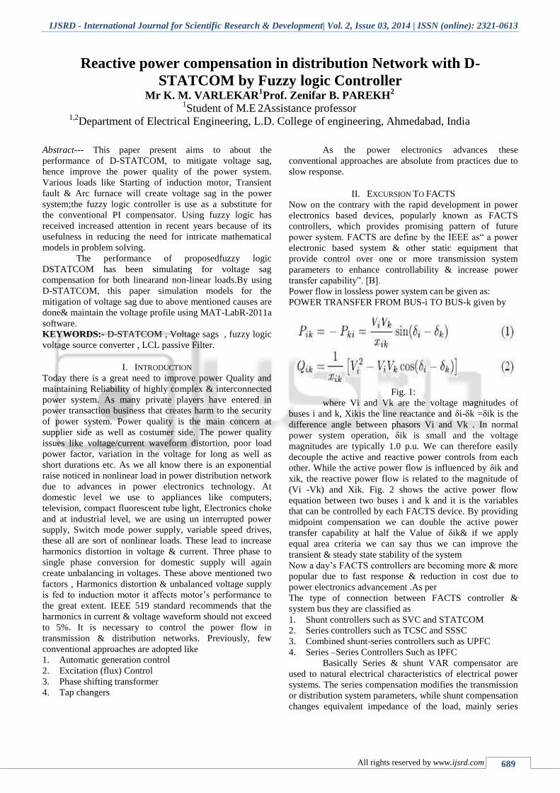
Power flow in lossless power system can be given as:
POWER TRANSFER FROM BUS-i TO BUS-k given by
Fig. 1:
where Vi and Vk are the voltage magnitudes of
buses i and k, Xikis the line reactance and δi-δk =δik is the
difference angle between phasors Vi and Vk . In normal
power system operation, δik is small and the voltage
magnitudes are typically 1.0 p.u. We can therefore easily
decouple the active and reactive power controls from each
other. While the active power flow is influenced by δik and
xik, the reactive power flow is related to the magnitude of
(Vi -Vk) and Xik. Fig. 2 shows the active power flow
equation between two buses i and k and it is the variables
that can be controlled by each FACTS device. By providing
midpoint compensation we can double the active power
transfer capability at half the Value of δik& if we apply
equal area criteria we can say thus we can improve the
transient & steady state stability of the system
Now a day’s FACTS controllers are becoming more & more
popular due to fast response & reduction in cost due to
power electronics advancement .As per
The type of connection between FACTS controller &
system bus they are classified as
1. Shunt controllers such as SVC and STATCOM
2. Series controllers such as TCSC and SSSC
3. Combined shunt-series controllers such as UPFC
4. Series –Series Controllers Such as IPFC
Basically Series & shunt VAR compensator are
used to natural electrical characteristics of electrical power
systems. The series compensation modifies the transmission
or distribution system parameters, while shunt compensation
changes equivalent impedance of the load, mainly series
Reactive power compensation in distribution Network with D-STATCOM by Fuzzy logic Controller
(IJSRD/Vol. 2/Issue 03/2014/183)
All rights reserved by www.ijsrd.com 690
controller will injects voltages, while shunt controller injects
current in the system. [B]
Fig. 2:
III. POWER QUALITY
Power Quality simply define in IEEE 1100 as, “The concept
of powering & grounding sensitive electronics equipment in
a manner suitable to the equipment” it also defines as, “ set
of electrical boundaries that allows a piece of equipment to
function in intended manner without any significant loss of
performance or life expectancy power quality simply means
if equipment operates correctly & reliably without being
damaged or stressed , we would say the electrical power is
of good quality, on other hand , if electrical equipment
malfunction or operate un reliably & damaged, we would
suspect that power quality is poor. Thus power quality
broadly refers to maintaining sinusoidal waveform of
voltage & current at rated magnitude & frequency. The
power quality issues are Power frequency variation, Supply
voltage distortion, Unbalanced load, DC offset on load
voltages, Notching in load voltages, Harmonics contain in
load, Poor load power factors Waveform Distortions,
Transients, Short duration voltage variation Long duration
voltage variation.
A. Power quality prime issues
Due to reactive power following effects arises
Voltage Sag
Voltage Swell
Voltage outage (Interruption)
Transient
Notches
Harmonics
IV. VOLTAGE SAG
As Per IEEE standards 1159-1995 ,recommended practices
for power quality is “Decrease in RMS value of voltage or
current at power frequency for duration from half cycle to
one minute, reported variation between 1 P.U. to 0.9 P.U.
Longer periodsof low or high voltage are referred as “Under
voltage” or “over voltage”.[A]
The Voltage sag or Dip is caused by abrupt
increase in reactive loading such as switch on the motors,
switch on the transformer, severe short circuit fault
Fig 1.2
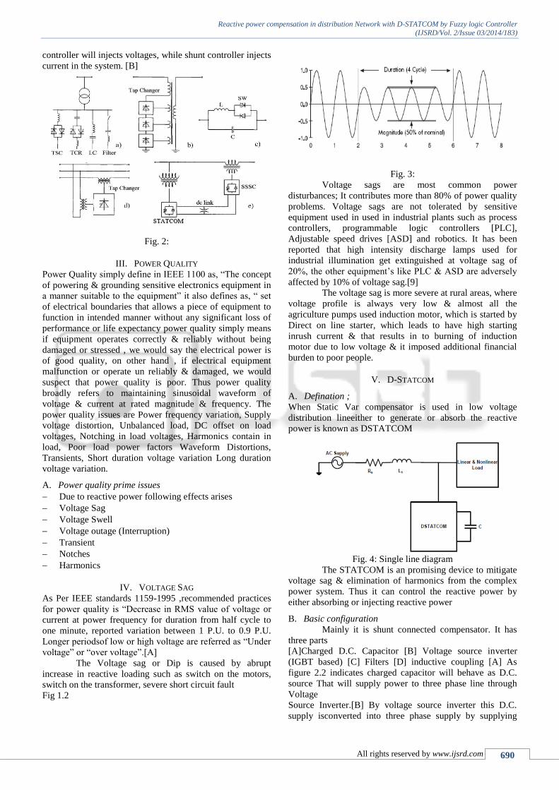
Fig. 3:
Voltage sags are most common power
disturbances; It contributes more than 80% of power quality
problems. Voltage sags are not tolerated by sensitive
equipment used in used in industrial plants such as process
controllers, programmable logic controllers [PLC],
Adjustable speed drives [ASD] and robotics. It has been
reported that high intensity discharge lamps used for
industrial illumination get extinguished at voltage sag of
20%, the other equipment’s like PLC & ASD are adversely
affected by 10% of voltage sag.[9]
The voltage sag is more severe at rural areas, where
voltage profile is always very low & almost all the
agriculture pumps used induction motor, which is started by
Direct on line starter, which leads to have high starting
inrush current & that results in to burning of induction
motor due to low voltage & it imposed additional financial
burden to poor people.
V. D-STATCOM
A. Defination ;
When Static Var compensator is used in low voltage
distribution lineeither to generate or absorb the reactive
power is known as DSTATCOM
Fig. 4: Single line diagram
The STATCOM is an promising device to mitigate
voltage sag & elimination of harmonics from the complex
power system. Thus it can control the reactive power by
either absorbing or injecting reactive power
B. Basic configuration
Mainly it is shunt connected compensator. It has
three parts
[A]Charged D.C. Capacitor [B] Voltage source inverter
(IGBT based) [C] Filters [D] inductive coupling [A] As
figure 2.2 indicates charged capacitor will behave as D.C.
source That will supply power to three phase line through
Voltage
Source Inverter.[B] By voltage source inverter this D.C.
supply isconverted into three phase supply by supplying

Reactive power compensation in distribution Network with D-STATCOM by Fuzzy logic Controller
(IJSRD/Vol. 2/Issue 03/2014/183)
All rights reserved by www.ijsrd.com 691
pulses to Insulated gate bi junction transiter[IGBTS]
[C]Filters are used to avoid switching ripples , which are
produces due to switching of IGBTs.
Fig. 5: Voltage source Converter
VI. OPERATION OF STATCOM
The D.C. Capacitor is used as an energy source, This D.C.
voltage is converted into three phase through voltage source
inverter. The switching of IGBT is done by PWM technique.
Switching ripples can be damped by providing filters When
STATCOM voltage [Vi] is higher than [Vs] system voltage,
Then it will feed the reactive power to the system & When
Vi<Vs. , then system will supply reactive power to charge
the capacitor. When Vs is equal to Vi, then STATCOM is in
floating state
Fig. 6: Operation of DSTATCOM
VII. VARIOUS CONTROLLERS
After deriving transfer function of cited system,
it’sbehaviour is checked usingvarious controllers First I
have started with PI Controller , Step Input[1/S] at
0.5second is given to themsystem&behaviour is observed ,
for C.R.O. is connected, which shows the waveformsof
input signal , error signal & output signal.
VIII. FUZZY CONTROLLER
A. Introductions
Fuzzy set theory is mathematical concept proposed
by Prof.L.A.Zadeh in 1965.this concept helps a lot to
improve the relationship between human and computers.
This control method can be regard as an adaptive control
based on a linguistic process, which is in turn base on the
prior experience, and heuristic rules used by human
operators. The implementation of such control consists of
translating the input variables to a language, like: positive
big, zero, negative medium, etc. and to establish control
rules so that the decision process can produce the
appropriate outputs. If necessary, these linguistic outputs are
transformed to numeric values.
Fuzzy logic control is one of the best and most
successful techniques among expert control strategies, and is
well known as an important tool to control non-linear,
complex, vague, and ill-defined systems. The use of fuzzy
set theory in providing effectiveness control based on the
knowledge and technical experience of operators and the
establishment of intelligent control have found favour in
industry.[11]
B. Fuzzy logic algorithm
Fuzzy logic is a mathematical theory and introduced by
Zadeh in 1965. Since its introduction, it has been use to
solve many different problems in electrical engineering
fields. Fuzzy logic is an effective approach in dealing with
electric power engineering problems such as stability
studies, load frequency control, unit commitment, and
reactive compensation in distribution networks. Fuzzy logic
is base on linguistic variables. The first step in designing
fuzzy inference mechanism is to identify effective input
variables and output decision variables, and then qualify
them with membership functions. Membership functions
determine that how variables belong to a fuzzy set. This
process is call fuzzification. After fuzzification, we should
define rules based on linguistic variables and the physical
dynamic of the system. Then fuzzy inference mechanism
determines effective rules and based on these rules, decision
variables are produce. Finally, the fuzzy decision variables
are convert to real numbers through the process of
defuzzification.[8]
C. Fuzzy logic controller methodology
Fuzzy logic control essentially involves the derivation of a
control law from heuristic and imprecise (fuzzy) rules. The
configuration of the Fuzzy logic control system that is
employed for designing the Fuzzy supplementary controller
is shown in fig 3.1.
Fig. 7:
The following steps are involved in the designing fuzzy
logic controller.
1) Choose the inputs to FLC (INPUT-CRISP):
The inputs to FLC used in this study are generator
terminal voltage deviation ( Vt) which are given by
Vt(pu) = Vref – Vt(pu)
Where
Vt= Transmission line voltage (pu)
Vref=Reference voltage per unit (constant 1)

Reactive power compensation in distribution Network with D-STATCOM by Fuzzy logic Controller
(IJSRD/Vol. 2/Issue 03/2014/183)
All rights reserved by www.ijsrd.com 692
2) Choose membership functions to represent the inputs
andoutputs in fuzzy set notation (FUZZIFICA TION):
Triangularmembership functions were selected for this study
as shown in Fig. with six linguistic variables chosen as
negative (NB), negative medium (NM), negative
small(NS),zero(ZE),positive small(PS),positive medium
(PM),positive big(PB)for both inputs and outputs. Thevalues
of the axes are given in fig 4.2.
Fig. 8: MF for input error
Fig. 9: Mf for input change in error
D. Develop fuzzy rules (FUZZY RULE BASE):
A set of decision rules relating the inputs to the controller
with the output are compiled and stored in the memory in
the form of decision table. Forty-nine rules for the present
study are developing as follows.
TABLE 3
E. FUZZY INFERENCE ENGINE:
Since there are N (seven) membership functions for
each input, there are (forty-nine ) possible combinations
resulting in M (seven) values for the decision variable u. All
the possible combinations of inputs, called states, and the
resulting control are arranged in a ( xM) fuzzy
relationship matrix. The membership values for the output
characterized by the M linguistic variables are then obtained
from the intersection of N2 values of membership function
(x) with the corresponding values of each decision
variables in the fuzzy relationship matrix.
Fig. 10:
F. Defuzzy to obtain crisp output (DEFUZZIFICATION):
The output FLC is converted to crisp value by Centre or
Gravity (COG) method in this study. The crisp value of FLC
in COG is express as,
crispoutput (u)=∑ ∫ ( )
∑ ∫ ( )
Where,
bi is the center of the membership function.
(i) is the membership of member i of output fuzzy set.
n is the number of discrete value i on the universal of
discourse.
Test system
Fig. 11:
The test system shown in figure 4.2 comprises a
230kv, 50 Hz transmission system, represented by a
thevenin equivalent, feeding into the primary side of a 3-
winding transformer connected in Y/Y/Y, 230/11/11 KV. A
varying load is connecting to the 11 kv, secondary side of
the transformer. A two level DSTATCOM is connected to
the 11 kv tertiary winding to provide instantaneous voltage
support at the load point. A 750 capacitor on the dc side
provide the DSTACOM energy storage capabilities.
Capacitor value calculated equation (4) using; dc voltage
find equation (5).
The percentage of sag for the system is calculated using the
following equation.
( ) ( ) ( )
( ) *100

Reactive power compensation in distribution Network with D-STATCOM by Fuzzy logic Controller
(IJSRD/Vol. 2/Issue 03/2014/183)
All rights reserved by www.ijsrd.com 693
G. Fuzzy Controller
In basic applications, the FL controller is use as a substitute
for the conventional PI compensator. The voltage error and
its derivative are the FL controller input crisp values. The
reference voltages for the PWM generator are the FL
controller crisp output commands.
When a FL controller is used, the tracking error
and transient overshoots of PWM can be considerably
reduced. This is because in contrast to the conventional PI
compensator-the control surface of the FL controller can be
shaped to define appropriate sensitivity for each operating
point. The FL controller can easily he implemented as an
off-line pre-calculated three-dimensional lookup table
consisting of the control surface.
The PI controller requires precise liner
mathematical models, which are difficult to obtain and fails
to perform satisfactorily under parameter variation,
nonlinearity, load disturbance. FLC are that they do not need
on accurate mathematical model. They can work with
imprecise input ,can handle none – linearity and they are
more robust than conventional controller .[2]
Fig. 12:
For the common PI control, the control parameters
are fixe, so the PI law can only guarantee good performance
in a local area in non-linear load. When the operation point
of the converter is change. The parameters of PI should he
designed again.
H. Control strategy for voltage sag mitigation
Fig. 13:
To mitigate voltage sag, the following figure will
indicate the control strategy, at start though positive
sequence analyses. The positive sequence comparator will
give out put in P.U, the comparator compares. The value
with the reference [1P.U], then the error is fed to fuzzy
controller. His fuzzy controller will generate actuating
signal, which is multiply by pi/180, thus we can convert the
sag into angel [radians, ].now one clock signal created &
added. Now it is [Wt+ ]. As with the addition &
subtraction of /3, it can be converted into [Wt + - /3]
& [Wt + + /3]. Then sin function is taken& that will
pass though triangular wave, which create pulse for IGBTs
of VSC.
Fig. 14:
IX. SIMULATION & RESULT
Simulations of voltage sag
Fig. 15:
Without insertion of DSTACOM
Fault
resistance
Rf,ῼ
Voltage
sags for
TLG
fault
(P.U)
Voltage
sags for
fault
DLG
fault
(P.U)
Voltage
sags for
LL fault
(P.U)
Voltage
sags for
SLG
fault
(P.U)
0.66 0.6600 0.7060 0.7580 0.8245
0.86 0.7520 0.7820 0.8175 0.8660
Table 4
Table 4 shows the overall result of voltage sags in
P.U for different types of fault. From the table, it can

Reactive power compensation in distribution Network with D-STATCOM by Fuzzy logic Controller
(IJSRD/Vol. 2/Issue 03/2014/183)
All rights reserved by www.ijsrd.com 694
observe that when the value of fault resistance is increase,
the voltage sag will also increase for different types of fault.
Three phase to ground fault with 0.66 ,0.6600 P.U scope
output
Fig. 16: Double line ground fault with 0.66 , 0.7060 P.U
scope output
Fig. 17: Line to line fault with 0.66 , 0.7580 P.U scope
output
Fig. 18: Single line to ground fault with 0.66 , 0.8245 P.U
scope output
Fig.19:
X. SIMULAION OF VOLTAGE SAG MITIGATION BY
D-STATCOM
Fig. 20: Result of voltage sags for different types of fault
with insertion of DSTACOM
Types
of fault
Without D-
STATCOM
(P.U)
With D-
STATCOM
(P.U)
Percentage of
improvement
%
TPG 0.6600 0.9428 28.28
DPG 0.7070 0.9825 27.55
LL 0.7580 1.0195 26.08
SPG 0.8245 0.9865 16.20
Table 5
Figure 5.6 show the simulation result of the test
system for different types of fault. The fault occurs during
(0.4s 0.6s) when the fault resistance is 0.66ῼ
Three phase to ground fault with 0.66 ,0.9428
P.U scope output
Fig. 21: Double line to ground fault with 0.66 ,0.9825 P.U
scope output
Fig. 22: Line to line fault with 0.66 ,1.0195 P.U scope
output

Reactive power compensation in distribution Network with D-STATCOM by Fuzzy logic Controller
(IJSRD/Vol. 2/Issue 03/2014/183)
All rights reserved by www.ijsrd.com 695
Fig. 23: Single line to ground fault with 0.66 ,0.9865 P.U
scope output
Fig. 24:
XI. CONCLUSION
The simulation result show that the voltage sags can be
mitigating by inserting D-STACOM to the distribution
system.
A fuzzy logic controlled D-STATCOM has been
simulated compensating reactive power in distribution
networks and compared result of simulation with the PI
conventional controller , we can see fuzzy logic controller
with linguistic variable is very simple and in the fuzzy
controller we does not require a mathematical model of the
system .
Comparison between PI& fuzzy logic controller
for transient fault
Types of
fault
Rf=0.66ῼ
D-
STACOM
with PI
controller
(P.U)
D-
STACOM
with fuzzy
logic
controller
(P.U)
Percentage of
improvement
(%)
TPG 0.9367 0.9428 0.60
DLG 0.9800 0.9825 0.25
LL 1.0168 1.0195 0.27
SLG 0.9837 0.9865 0.28
REFERENCE
[1] Noramin Ismail, 2 Wan Norainin Wan Abdullah
“Enhancement of Power Quality in Distribution System
Using D-STATCOM” 978-1-4244-7128-7/10 ©2010
IEEE
[2] Seyyedhosseinhosseini ,rezarahnavard , yousefebrahimi
“ reactive power compensation in distribution network
with STATCOM by fuzzy logic theory application” 1-
4244-0449-5/06 2006 IEEE.
[3] R. S. Dhekekar, N. V. Srikanth , “VSC for reactive
power control of transmission line with fast response”
987-1-4244-9074-5/10 IEEE
[4] Harish suryanarayana and Mahesh k. Mishra “ fuzzy
logic based supervision of DC link PI


![Reactive Power Compensation[1]](https://img.dokumen.tips/doc/110x75/577ccf3f1a28ab9e788f40c0/reactive-power-compensation1.jpg)


