Embed Size (px)
Citation preview
1
Operator Guide
For
Raptor 6
Software
.

2
3
Contents 1.0 Introduction .................................................................................................................................................. 7
1.1 Convention ................................................................................................................................................... 7
1.2 Inks ............................................................................................................................................................... 7
1.3 Technical Support ........................................................................................................................................ 7
1.4 Raptor Software ........................................................................................................................................... 8
2.0 Installing Raptor Software ........................................................................................................................ 10
2.1 Installing Software ..................................................................................................................................... 10
2.2 Dongle Installation ..................................................................................................................................... 10
3.0 Getting Started ........................................................................................................................................... 12
3.1 System Power Up ....................................................................................................................................... 12
3.2 Printing ....................................................................................................................................................... 12
4.0 Understanding the Software Interface ....................................................................................................... 14
4.1 The Main Window ..................................................................................................................................... 14
4.1.1 Title Bar.................................................................................................................................................. 15
4.1.1a Tool Bar.................................................................................................................................................. 15
4.1.1b Menu Bar ................................................................................................................................................ 15
4.1.2 Display Area ........................................................................................................................................... 15
4.1.3 Tab Selection Area ................................................................................................................................. 15
4.1.4 Status Bar ............................................................................................................................................... 15
4.2 Other Helpful Windows ............................................................................................................................. 15
4.2.1 Data Entry Font ...................................................................................................................................... 15
4.2.2 Customize Menu Bar .............................................................................................................................. 15
4.2.3 Options ......................................................................................................................................................... 16
5.0 Importing Data ........................................................................................................................................... 19
5.1 Data File Options ....................................................................................................................................... 19
5.2 Custom Data Files ...................................................................................................................................... 20
5.3 Opening Data Files .................................................................................................................................... 20
5.4 Viewing Records ........................................................................................................................................ 20
5.5 Finding Records ......................................................................................................................................... 21
5.6 Validating Postal Barcodes ........................................................................................................................ 21
5.7 Setting Start and Stop Records .................................................................................................................. 21
5.8 Changing the Data Font ............................................................................................................................. 22
6.0 Open Existing Templates ........................................................................................................................... 24
4
6.2 Creating New Templates............................................................................................................................ 24
6.3 Saving Templates ....................................................................................................................................... 24
6.4 Understanding the Template Display Area ................................................................................................ 24
6.5 Placing New Items ..................................................................................................................................... 26
6.5.1 Record Blocks ........................................................................................................................................ 26
6.5.2 Message Lines ........................................................................................................................................ 28
6.5.3 Conditional Message Lines .................................................................................................................... 28
6.5.4 Indicia ..................................................................................................................................................... 29
6.5.5 Bitmaps................................................................................................................................................... 30
6.5.6 Barcodes ................................................................................................................................................. 33
6.5.7 Counters ................................................................................................................................................. 38
6.5.8 Timestamps ............................................................................................................................................ 39
6.5.9 Shift Code ............................................................................................................................................... 41
6.5.10 User Insert .............................................................................................................................................. 42
6.6 Editing Options .......................................................................................................................................... 43
6.6.1 Selecting Objects .................................................................................................................................... 43
6.6.2 Moving or Rotating Objects ................................................................................................................... 43
6.6.3 Undoing and Redoing Changes .............................................................................................................. 43
6.6.4 Duplicating Objects ................................................................................................................................ 43
6.6.5 Deleting Objects ..................................................................................................................................... 43
6.6.7 Aligning Objects .................................................................................................................................... 44
6.6.8 Move to Print Area ................................................................................................................................. 44
6.6.9 Layering Objects .................................................................................................................................... 45
6.6.10 Set Background ...................................................................................................................................... 45
6.6.11 Scanning Data ........................................................................................................................................ 46
6.7 Viewing Options ........................................................................................................................................ 46
6.8 N Up Option ............................................................................................................................................... 46
6.9 Print Proof .................................................................................................................................................. 47
7.0 Print Setup .................................................................................................................................................. 49
7.1 Print Setup Tab .......................................................................................................................................... 49
7.2 Errors Tab .................................................................................................................................................. 50
7.3 Sort Tab ...................................................................................................................................................... 50
7.4 Counters Tab .............................................................................................................................................. 50
7.5 Clocks Tab ................................................................................................................................................. 51
7.6 Time Stamps Tab ....................................................................................................................................... 52
7.7 Shift Definitions Tab.................................................................................................................................. 53
5
7.8 User Inputs Tab .......................................................................................................................................... 54
7.9 Other Tab ................................................................................................................................................... 55
8.0 Printing ....................................................................................................................................................... 57
8.1 Creating, Opening, and Saving Jobs .......................................................................................................... 57
8.1.1 Creating Jobs .......................................................................................................................................... 57
8.1.2 Opening Existing Jobs ............................................................................................................................ 57
8.1.3 Saving Jobs ............................................................................................................................................. 57
8.2 Printing Jobs............................................................................................................................................... 57
8.3 Checking Print Status ................................................................................................................................. 58
8.3.1 Viewing the Job Log .............................................................................................................................. 59
8.4 Reprints ...................................................................................................................................................... 59
9.0 Purging the Eagle Print Head ..................................................................................................................... 62
9.1 Priming the Eagle Print Head .................................................................................................................... 66
9.2 Prepare for Storage .................................................................................................................................... 72

6
Section One
Introduction
7
1.0 Introduction This manual is intended for equipment operators with a basic knowledge of Microsoft Windows operating
system. Some basic experience with the Raptor software setup is assumed.
This manual includes information about the physical printer and how the user can set up print jobs. This manual
will also cover the basics of printer maintenance both software and hardware.
1.1 Convention This manual uses specific terms at times. You may sometimes see directions written out like this: File>Save.
When you see this, it means to go to the “File” menu in the toolbar by hovering your mouse over the name in
the toolbar and then select the second item in the list (such as “Save”).
1.2 Inks Replacement ink is available from Think Ink Inc. Getting your ink from Think Ink entitles you to free technical
support and great ink prices.
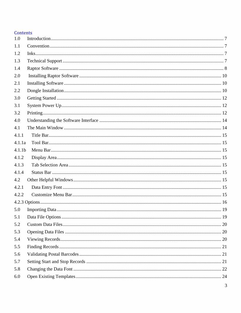
1.3 Technical Support If you need assistance, you can use the On-Line Connection through the Raptor software at any point. Just
click the logo in the right side of the Raptor software window.
If further assistance is needed, contact at [email protected] or call toll free at 1.800.768.0154 Monday through
Friday 8:30AM to 6:30PM EST.
If you do call, you may be asked for a software version number. This can be seen on the Title Bar of the main
menu and can also be found in the “Help” tab, go to Help>About, to view the software version.
Image 1.3: Main Window

8
1.4 Raptor Software The Raptor software is designed to work with the following print systems, Eagle and Eagle AMS Printers. This
manual will detail how to use the software. The software runs on Windows 7 later versions only. This manual
will explain each of the following steps: loading templates, print data sets, and even help with maintenance the
print system.

9
Section Two
Software Installation
10
2.0 Installing Raptor Software The technician should have set up the computer for you. If, for whatever reason, the software needs to be
reinstalled, then the necessary files are in the “Raptor 6” files you were given. Should you need to reinstall
your software, install the provided version of the Raptor software, update to the current version, and install
the dongle software.
Should you just need to update your software, simply follow the instructions for updating in section 2.1.
2.1 Installing Software The original installation program should be included in the “Raptor 6” files you were provided with
upon installation.
Steps for installing software:
1. Disable antivirus software.
2. Run “Raptor 6 Install.exe.
3. Follow setup steps.
4. Run Raptor 6.0.0.0 program version you’d like to install the 6.0.0.0 will be the actual
version contained in the installation that will be installed. Note you will receive an error
from the setup program if Raptor 6 install has not been completed properly.
5. Follow setup steps.
6. Open program.
Note: When Raptor 6 program is run, you will be prompted to “Run as administrator”
when necessary. This is a one-time requirement. From the start up menu, right click the
program and select “Run as administrator.”
7. Verify software version displayed in the program’s Title bar
8. Re-enable antivirus.
9. Updating Software
Software updates are up to the user. They are provided as Raptor 6.0.0.0 Install with 6.0.0.0
being the actual version of the program. Go to [url] to find the updates.
2.2 Dongle Installation (Note: If the current dongle is lit there should be no need to perform this step)
The USB dongle is the software key. The system will not print properly without the dongle. A “Printer
Setup Error” will occur if there is no dongle detected. A dongle is only required once the PRINT button
is used. If it is necessary to install the dongle software, open the file “HASPUserSetup.exe from the
C:/Program Files () Raptor 6/Extras folder.
Image 2.3

11
Section Three
Getting Started
12
3.0 Getting Started The Raptor Software is an application for Windows 7 and later that will allow you to lay out fixed or variable
data that includes text, numbers, barcodes, and graphics.
Before you begin, you must make sure the printer is up and running.
3.1 System Power Up The system needs to be powered up in the correct order.
The proper power up order is:
1. Power up the PC and log into Windows.
2. Power up the Raptor controller and Raptor Printer IO Controller.
3. Run Raptor Software.
4. Wait until LED on Controller turns solid green.
5. The font screen should show IDLE when everything is connected and ready
6. Ink supply level will automatically be displayed on the programs front screen.
3.2 Printing The Raptor Software is a powerful tool that will help you print. The printing process contains three main
sections: the print job, the optional template, and data.
The basic steps for most print jobs are:
1. Import Data.
2. Perform Print Setup.
3. Create a Template.
4. Create a Print Job.
5. Print the Job.

13
Section Four
Understanding The
Software Interface
14
4.0 Understanding the Software Interface To open the application, simply double click the Raptor 6 icon on your desktop.
Please note: You may be prompted to open the application as an administrator. If this is the case right-click
the icon and select “Run as administrator.”
The MCS Logo will appear on the screen and the main window will open.
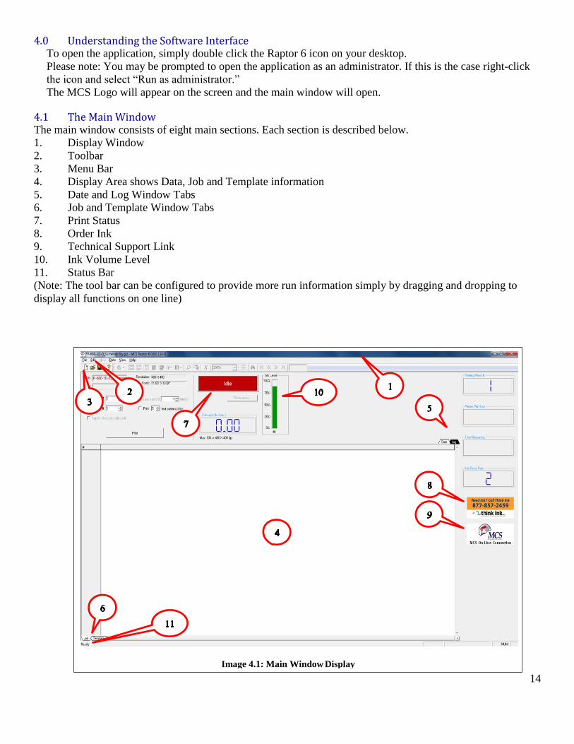
4.1 The Main Window The main window consists of eight main sections. Each section is described below.
1. Display Window
2. Toolbar
3. Menu Bar
4. Display Area shows Data, Job and Template information
5. Date and Log Window Tabs
6. Job and Template Window Tabs
7. Print Status
8. Order Ink
9. Technical Support Link
10. Ink Volume Level
11. Status Bar
(Note: The tool bar can be configured to provide more run information simply by dragging and dropping to
display all functions on one line)
Image 4.1: Main Window Display
15
4.1.1 Title Bar The title bar simply displays the name of the program and project. Like other Windows programs you can use
the buttons on the upper left to close, hide, and resize the window.
4.1.1a Tool Bar The toolbar looks like the toolbar from many other programs. It consists of “File,” “Edit,” “New,” “Data,”
“View,” and “Help.”
4.1.1b Menu Bar The menu bar consists of a “Job Tab”, a “Template Tab” and a “Data Tab” as well as a “Log Tab” shown in the
screen shoot (refer to page Image 4.1).
4.1.2 Display Area This display area (refer to item 4 in Image 4.1) will display the data if on the “Data” tab and the template if on
the “Template” tab.
4.1.3 Tab Selection Area The “Job” and “Template” tabs are located on the bottom and left of the display window. The “Log” and “Data”
tabs are located in the upper right of the title bar display window. These tabs allow you to change the data of the
specific job (refer to item 5 & 6 in Image 4.1). The “Template” tab is a full-screen view and when selected the
“Log” and “Data” tabs are not available.
4.1.4 Status Bar The status bar is located at the bottom of the window and lets you know if the system is ready to print. Please
refer to item 11 in Image 4.1 to see where the status bar is located.
4.2 Other Helpful Windows
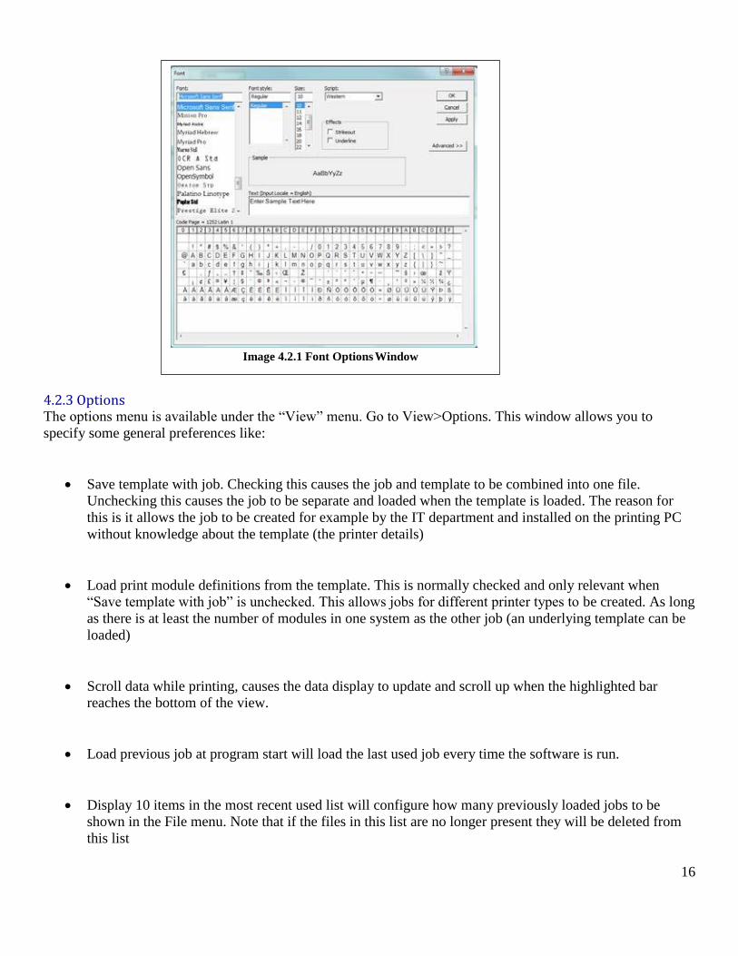
4.2.1 Data Entry Font This window is found under View Tab drag down> this will allow you to adjust the font type style and size
(refer to Image 4.2.1 below).
4.2.2 Customize Menu Bar The customize menu bar is located under the “View” menu. Go to View>Customize Menu. This option allows
you to customize which options you might like to add or remove from your menu bar.
16
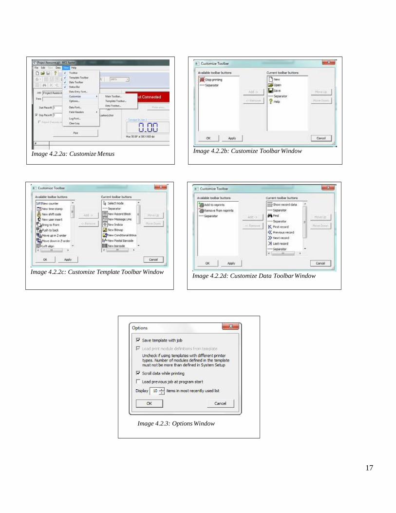
4.2.3 Options The options menu is available under the “View” menu. Go to View>Options. This window allows you to
specify some general preferences like:
Save template with job. Checking this causes the job and template to be combined into one file.
Unchecking this causes the job to be separate and loaded when the template is loaded. The reason for
this is it allows the job to be created for example by the IT department and installed on the printing PC
without knowledge about the template (the printer details)
Load print module definitions from the template. This is normally checked and only relevant when
“Save template with job” is unchecked. This allows jobs for different printer types to be created. As long
as there is at least the number of modules in one system as the other job (an underlying template can be
loaded)
Scroll data while printing, causes the data display to update and scroll up when the highlighted bar
reaches the bottom of the view.
Load previous job at program start will load the last used job every time the software is run.
Display 10 items in the most recent used list will configure how many previously loaded jobs to be
shown in the File menu. Note that if the files in this list are no longer present they will be deleted from
this list
Image 4.2.1 Font Options Window
17
Image 4.2.2a: Customize Menus
Image 4.2.2b: Customize Toolbar Window
Image 4.2.2c: Customize Template Toolbar Window
Image 4.2.2d: Customize Data Toolbar Window
Image 4.2.3: Options Window

18
Section Five
Importing data
19
5.0 Importing Data To load your data set, you will need to first set the data file options. Then you can import the file.
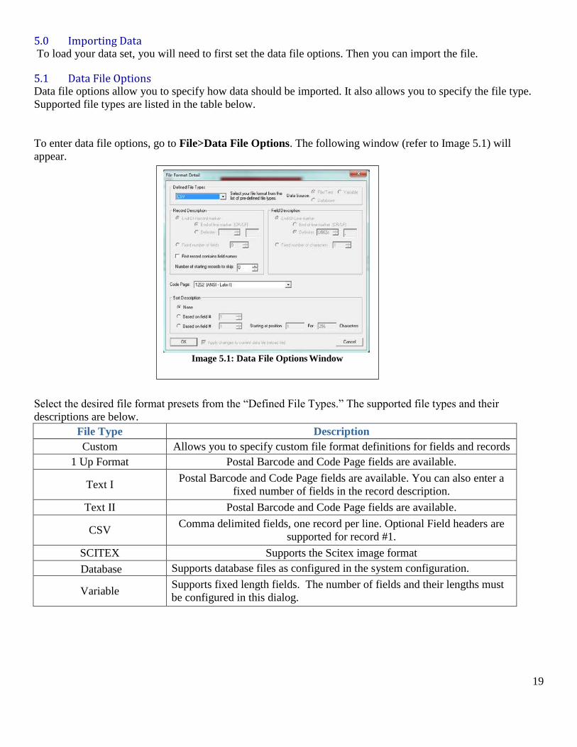
5.1 Data File Options Data file options allow you to specify how data should be imported. It also allows you to specify the file type.
Supported file types are listed in the table below.
To enter data file options, go to File>Data File Options. The following window (refer to Image 5.1) will
appear.
Select the desired file format presets from the “Defined File Types.” The supported file types and their
descriptions are below.
File Type Description
Custom Allows you to specify custom file format definitions for fields and records
1 Up Format Postal Barcode and Code Page fields are available.
Text I Postal Barcode and Code Page fields are available. You can also enter a
fixed number of fields in the record description.
Text II Postal Barcode and Code Page fields are available.
CSV Comma delimited fields, one record per line. Optional Field headers are
supported for record #1.
SCITEX Supports the Scitex image format
Database Supports database files as configured in the system configuration.
Variable Supports fixed length fields. The number of fields and their lengths must
be configured in this dialog.
Image 5.1: Data File Options Window
20
5.2 Custom Data Files Custom data files require the most configuration because the program can make no assumptions about file type.
To enter custom data file options:
1. Open the “Data File Options” window by going to File>Data File Options.
2. Select “Custom” from the “Defined File Types” pull down section. (Refer to image 5.1 above)
3. Click the radio button for the data source type (i.e. File/Text, Variable, or Database).
Please note: Only select Variable of Database if you know the file is of those types.
For Database files, enter the Database Parameters selection statement only if your database has
multiple tables
4. Enter the Record Description.
For File/Text source type, select the end-of-record marker, end-of-line marker, or end-of-record
delimiter. The end-of-line marker can be a carriage return (CR) or line feed (LF). A record
delimiter is the hexadecimal value for a specific character, like a comma (, = U002C) or pipe
(| = U007C).
For Variable source type, use the “Add/Modify” field definition button to add field level
definitions. Enter “field number,” “starting” and “ending” positions, and “field length” for each
field.
5. Enter the Postal Barcode Description
Please note: Postal barcodes are 12 digits long and include the zip code plus four, deliver point,
and a check digit.
If you select “None,” then the software will not look for this value.
If you choose “Select from Data,” then the software looks at all fields for this data. You may also
specify a field number along with a specific amount of characters to look at.
6. Select the Code Page from the pull down.
These options select the standard used to display text.
Note: ANSI-Latin is most often used for the American alphabet.
7. Click “OK” to save your settings.
5.3 Opening Data Files Data files cannot be created in Raptor Software and must be created in other software programs or utilities. The
data file settings need to be updated if you have not already done so (see Custom Data Files section 5.2). Data
files must then be opened and reviewed before they can be attached to jobs.
To open the file:
1. Make sure “Tab” is selected in the tab selection area.
2. Go to File>Open Data Files or click the open file icon on the menu bar.
3. Navigate to the file’s location and click open.
4. The file will be displayed in the display area under the “Data” tab.
5.4 Viewing Records Navigating through large groups of data is made easy with data menu options. Use the navigation icons on the
toolbar to go to the “First Record,” “Previous Record,” “Next Record,” “Last Record,” “Go to Record...,” and
“Find...” (The find function is described in more detail in the Finding Records section 5.5). (See image 5.5 on
page 9).
21
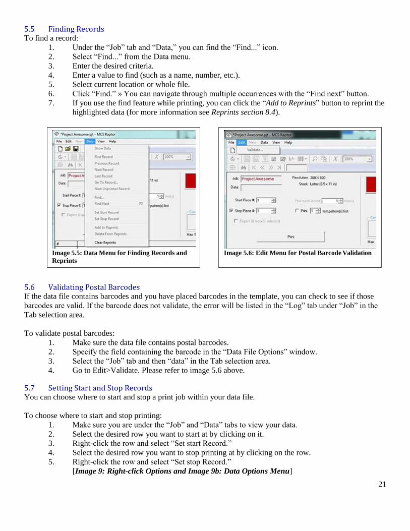
5.5 Finding Records To find a record:
1. Under the “Job” tab and “Data,” you can find the “Find...” icon.
2. Select “Find...” from the Data menu.
3. Enter the desired criteria.
4. Enter a value to find (such as a name, number, etc.).
5. Select current location or whole file.
6. Click “Find.” » You can navigate through multiple occurrences with the “Find next” button.
7. If you use the find feature while printing, you can click the “Add to Reprints” button to reprint the
highlighted data (for more information see Reprints section 8.4).
5.6 Validating Postal Barcodes If the data file contains barcodes and you have placed barcodes in the template, you can check to see if those
barcodes are valid. If the barcode does not validate, the error will be listed in the “Log” tab under “Job” in the
Tab selection area.
To validate postal barcodes:
1. Make sure the data file contains postal barcodes.
2. Specify the field containing the barcode in the “Data File Options” window.
3. Select the “Job” tab and then “data” in the Tab selection area.
4. Go to Edit>Validate. Please refer to image 5.6 above.
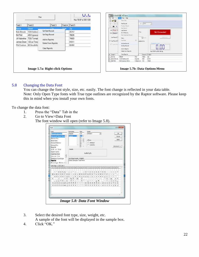
5.7 Setting Start and Stop Records You can choose where to start and stop a print job within your data file.
To choose where to start and stop printing:
1. Make sure you are under the “Job” and “Data” tabs to view your data.
2. Select the desired row you want to start at by clicking on it.
3. Right-click the row and select “Set start Record.”
4. Select the desired row you want to stop printing at by clicking on the row.
5. Right-click the row and select “Set stop Record.”
[Image 9: Right-click Options and Image 9b: Data Options Menu]
Image 5.5: Data Menu for Finding Records and
Reprints
Image 5.6: Edit Menu for Postal Barcode Validation
22
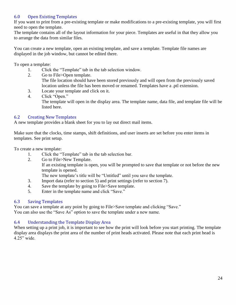
5.8 Changing the Data Font You can change the font style, size, etc. easily. The font change is reflected in your data table.
Note: Only Open Type fonts with True type outlines are recognized by the Raptor software. Please keep
this in mind when you install your own fonts.
To change the data font:
1. Press the “Data” Tab in the
2. Go to View>Data Font
The font window will open (refer to Image 5.8).
3. Select the desired font type, size, weight, etc.
A sample of the font will be displayed in the sample box.
4. Click “OK.”
Image 5.7a: Right-click Options
Image 5.7b: Data Options Menu
Image 5.8: Data Font Window

23
Section Six
Templates
24
6.0 Open Existing Templates If you want to print from a pre-existing template or make modifications to a pre-existing template, you will first
need to open the template.
The template contains all of the layout information for your piece. Templates are useful in that they allow you
to arrange the data from similar files.
You can create a new template, open an existing template, and save a template. Template file names are
displayed in the job window, but cannot be edited there.
To open a template:
1. Click the “Template” tab in the tab selection window.
2. Go to File>Open template.
The file location should have been stored previously and will open from the previously saved
location unless the file has been moved or renamed. Templates have a .ptl extension.
3. Locate your template and click on it.
4. Click “Open.”
The template will open in the display area. The template name, data file, and template file will be
listed here.
6.2 Creating New Templates A new template provides a blank sheet for you to lay out direct mail items.
Make sure that the clocks, time stamps, shift definitions, and user inserts are set before you enter items in
templates. See print setup.
To create a new template:
1. Click the “Template” tab in the tab selection bar.
2. Go to File>New Template.
If an existing template is open, you will be prompted to save that template or not before the new
template is opened.
The new template’s title will be “Untitled” until you save the template.
3. Import data (refer to section 5) and print settings (refer to section 7).
4. Save the template by going to File>Save template.
5. Enter in the template name and click “Save.”
6.3 Saving Templates You can save a template at any point by going to File>Save template and clicking “Save.”
You can also use the “Save As” option to save the template under a new name.
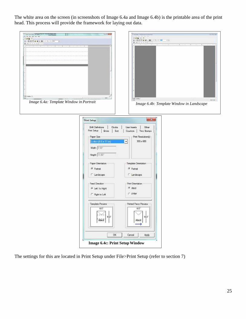
6.4 Understanding the Template Display Area When setting up a print job, it is important to see how the print will look before you start printing. The template
display area displays the print area of the number of print heads activated. Please note that each print head is
4.25” wide.
25
The white area on the screen (in screenshots of Image 6.4a and Image 6.4b) is the printable area of the print
head. This process will provide the framework for laying out data.
The settings for this are located in Print Setup under File>Print Setup (refer to section 7)
Image 6.4a: Template Window in Portrait
Image 6.4b: Template Window in Landscape
Image 6.4c: Print Setup Window
26
6.5 Placing New Items You can place a variety of items in your template. For the best results, data should be imported before placing
blocks.
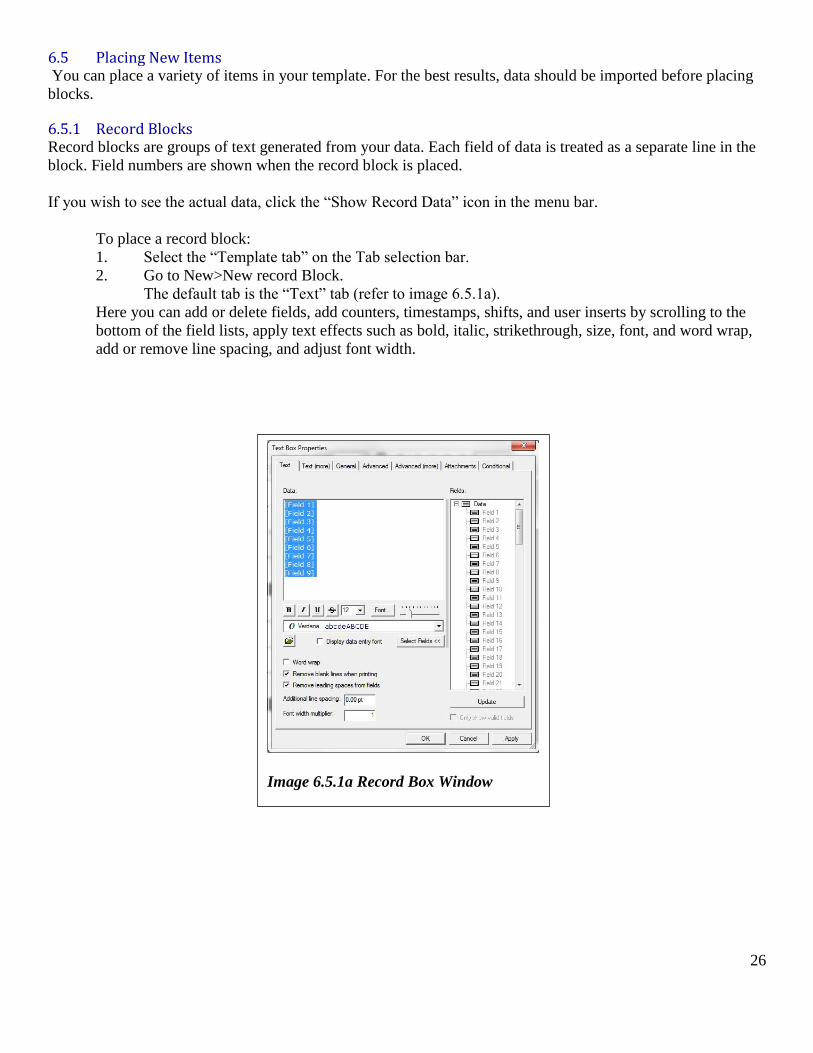
6.5.1 Record Blocks Record blocks are groups of text generated from your data. Each field of data is treated as a separate line in the
block. Field numbers are shown when the record block is placed.
If you wish to see the actual data, click the “Show Record Data” icon in the menu bar.
To place a record block:
1. Select the “Template tab” on the Tab selection bar.
2. Go to New>New record Block.
The default tab is the “Text” tab (refer to image 6.5.1a).
Here you can add or delete fields, add counters, timestamps, shifts, and user inserts by scrolling to the
bottom of the field lists, apply text effects such as bold, italic, strikethrough, size, font, and word wrap,
add or remove line spacing, and adjust font width.
Image 6.5.1a Record Box Window
27
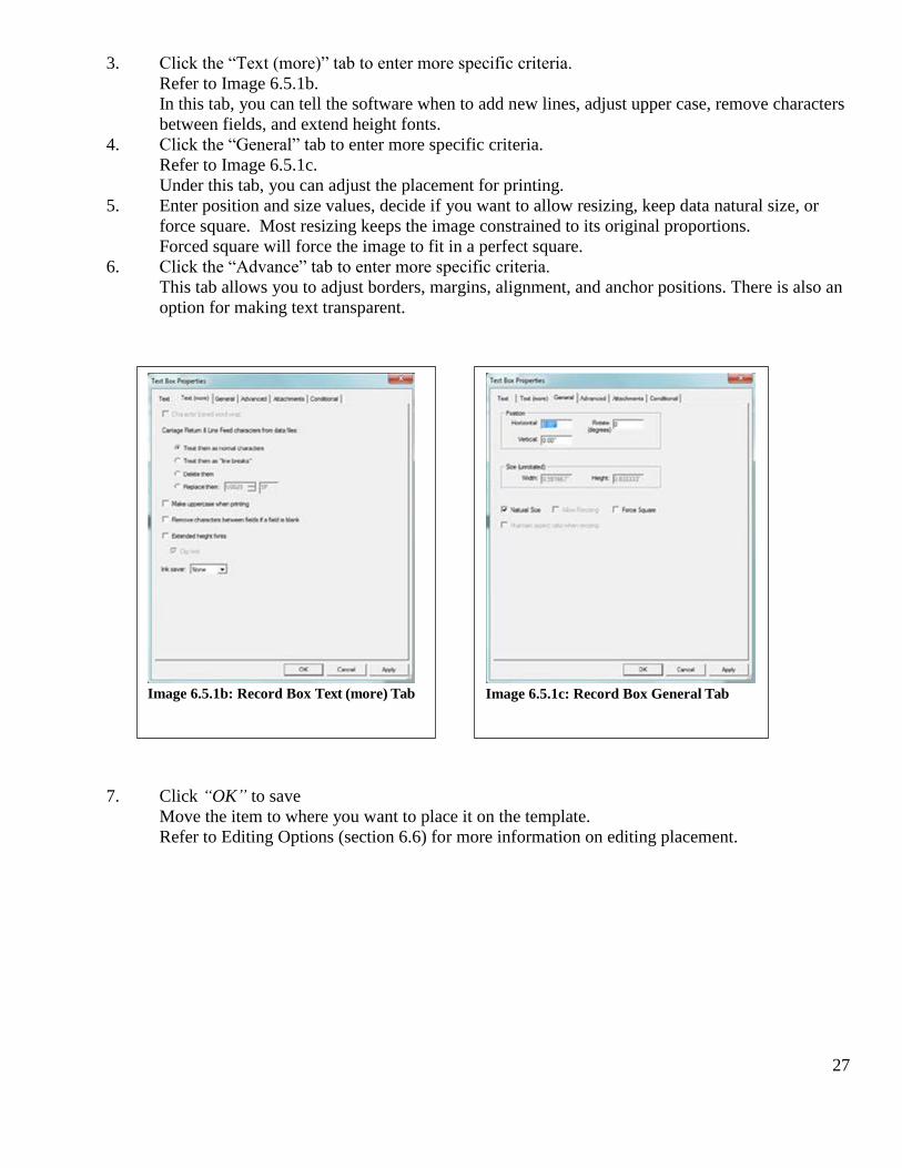
3. Click the “Text (more)” tab to enter more specific criteria.
Refer to Image 6.5.1b.
In this tab, you can tell the software when to add new lines, adjust upper case, remove characters
between fields, and extend height fonts.
4. Click the “General” tab to enter more specific criteria.
Refer to Image 6.5.1c.
Under this tab, you can adjust the placement for printing.
5. Enter position and size values, decide if you want to allow resizing, keep data natural size, or
force square. Most resizing keeps the image constrained to its original proportions.
Forced square will force the image to fit in a perfect square.
6. Click the “Advance” tab to enter more specific criteria.
This tab allows you to adjust borders, margins, alignment, and anchor positions. There is also an
option for making text transparent.
7. Click “OK” to save
Move the item to where you want to place it on the template.
Refer to Editing Options (section 6.6) for more information on editing placement.
Image 6.5.1b: Record Box Text (more) Tab
Image 6.5.1c: Record Box General Tab
28
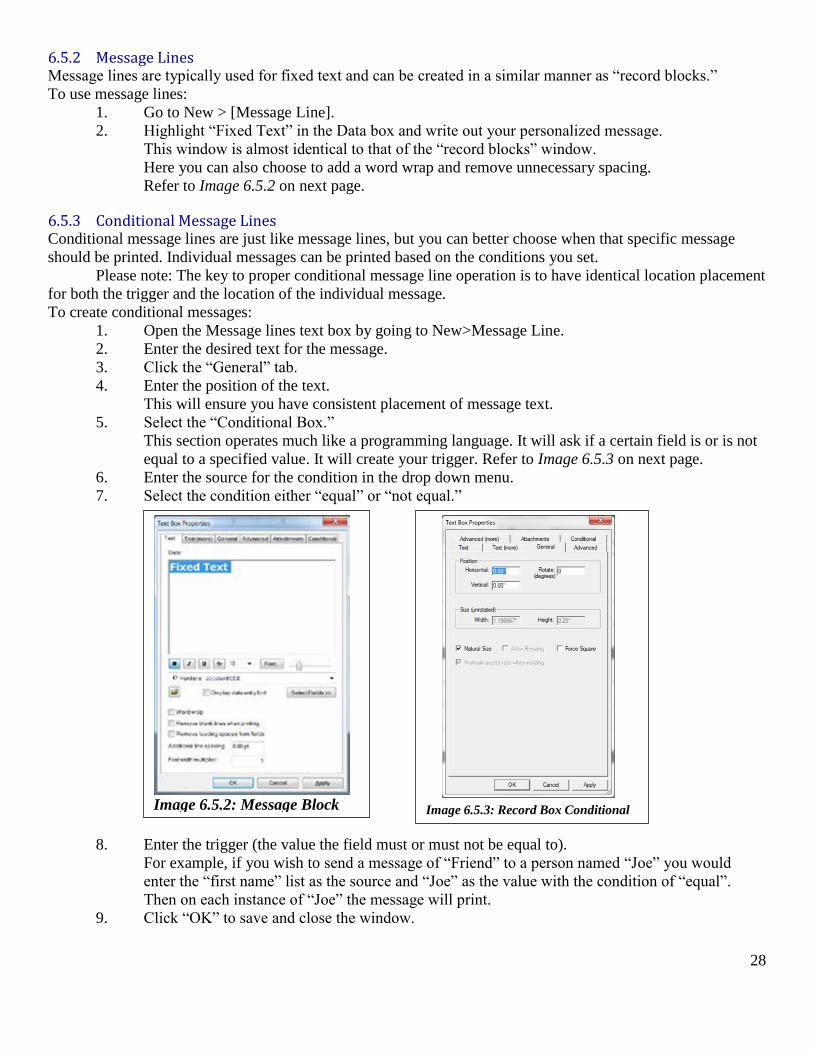
6.5.2 Message Lines Message lines are typically used for fixed text and can be created in a similar manner as “record blocks.”
To use message lines:
1. Go to New > [Message Line].
2. Highlight “Fixed Text” in the Data box and write out your personalized message.
This window is almost identical to that of the “record blocks” window.
Here you can also choose to add a word wrap and remove unnecessary spacing.
Refer to Image 6.5.2 on next page.
6.5.3 Conditional Message Lines Conditional message lines are just like message lines, but you can better choose when that specific message
should be printed. Individual messages can be printed based on the conditions you set.
Please note: The key to proper conditional message line operation is to have identical location placement
for both the trigger and the location of the individual message.
To create conditional messages:
1. Open the Message lines text box by going to New>Message Line.
2. Enter the desired text for the message.
3. Click the “General” tab.
4. Enter the position of the text.
This will ensure you have consistent placement of message text.
5. Select the “Conditional Box.”
This section operates much like a programming language. It will ask if a certain field is or is not
equal to a specified value. It will create your trigger. Refer to Image 6.5.3 on next page.
6. Enter the source for the condition in the drop down menu.
7. Select the condition either “equal” or “not equal.”
8. Enter the trigger (the value the field must or must not be equal to).
For example, if you wish to send a message of “Friend” to a person named “Joe” you would
enter the “first name” list as the source and “Joe” as the value with the condition of “equal”.
Then on each instance of “Joe” the message will print.
9. Click “OK” to save and close the window.
Image 6.5.2: Message Block
Image 6.5.3: Record Box Conditional
Window
29
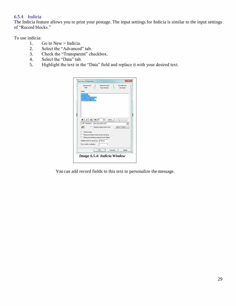
6.5.4 Indicia The Indicia feature allows you to print your postage. The input settings for Indicia is similar to the input settings
of “Record blocks.”
To use indicia:
1. Go to New > Indicia.
2. Select the “Advanced” tab.
3. Check the “Transparent” checkbox.
4. Select the “Data” tab.
5. Highlight the text in the “Data” field and replace it with your desired text.
You can add record fields to this text to personalize the message.
Image 6.5.4: Indicia Window
30
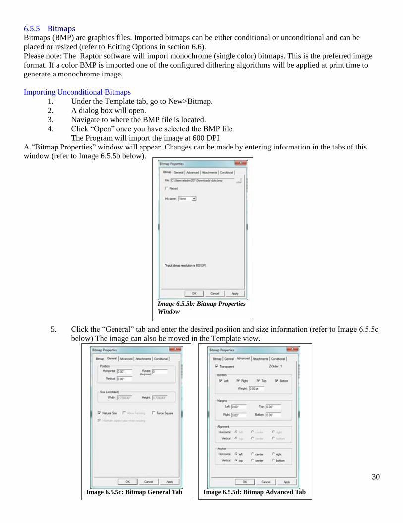
6.5.5 Bitmaps Bitmaps (BMP) are graphics files. Imported bitmaps can be either conditional or unconditional and can be
placed or resized (refer to Editing Options in section 6.6).
Please note: The Raptor software will import monochrome (single color) bitmaps. This is the preferred image
format. If a color BMP is imported one of the configured dithering algorithms will be applied at print time to
generate a monochrome image.
Importing Unconditional Bitmaps
1. Under the Template tab, go to New>Bitmap.
2. A dialog box will open.
3. Navigate to where the BMP file is located.
4. Click “Open” once you have selected the BMP file.
The Program will import the image at 600 DPI
A “Bitmap Properties” window will appear. Changes can be made by entering information in the tabs of this
window (refer to Image 6.5.5b below).
5. Click the “General” tab and enter the desired position and size information (refer to Image 6.5.5c
below) The image can also be moved in the Template view.
Image 6.5.5b: Bitmap Properties
Window
Image 6.5.5c: Bitmap General Tab
Image 6.5.5d: Bitmap Advanced Tab
31
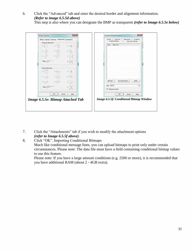
6. Click the “Advanced” tab and enter the desired border and alignment information.
(Refer to image 6.5.5d above)
This step is also where you can designate the BMP as transparent (refer to Image 6.5.5e below)
7. Click the “Attachments” tab if you wish to modify the attachment options
(refer to Image 6.5.5f above).
8. Click “OK”. Importing Conditional Bitmaps
Much like conditional message lines, you can upload bitmaps to print only under certain
circumstances. Please note: The data file must have a field containing conditional bitmap values
to use this feature.
Please note: If you have a large amount conditions (e.g. 2500 or more), it is recommended that
you have additional RAM (about 2 - 4GB extra).
Image 6.5.5e: Bitmap Attached Tab
Image 6.5.5f: Conditional Bitmap Window
32
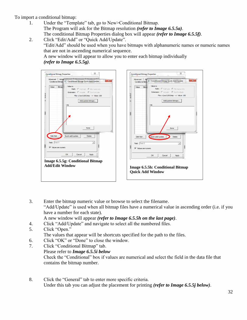
To import a conditional bitmap:
1. Under the “Template” tab, go to New>Conditional Bitmap.
The Program will ask for the Bitmap resolution (refer to Image 6.5.5a).
The conditional Bitmap Properties dialog box will appear (refer to Image 6.5.5f).
2. Click “Edit/Add” or “Quick Add/Update”.
“Edit/Add” should be used when you have bitmaps with alphanumeric names or numeric names
that are not in ascending numerical sequence.
A new window will appear to allow you to enter each bitmap individually
(refer to Image 6.5.5g).
3. Enter the bitmap numeric value or browse to select the filename.
“Add/Update” is used when all bitmap files have a numerical value in ascending order (i.e. if you
have a number for each state).
A new window will appear (refer to Image 6.5.5h on the last page).
4. Click “Add/Update” and navigate to select all the numbered files.
5. Click “Open.”
The values that appear will be shortcuts specified for the path to the files.
6. Click “OK” or “Done” to close the window.
7. Click “Conditional Bitmap” tab.
Please refer to Image 6.5.5i below
Check the “Conditional” box if values are numerical and select the field in the data file that
contains the bitmap number.
8. Click the “General” tab to enter more specific criteria.
Under this tab you can adjust the placement for printing (refer to Image 6.5.5j below).
Image 6.5.5g: Conditional Bitmap
Add/Edit Window
Image 6.5.5h: Conditional Bitmap
Quick Add Window
33
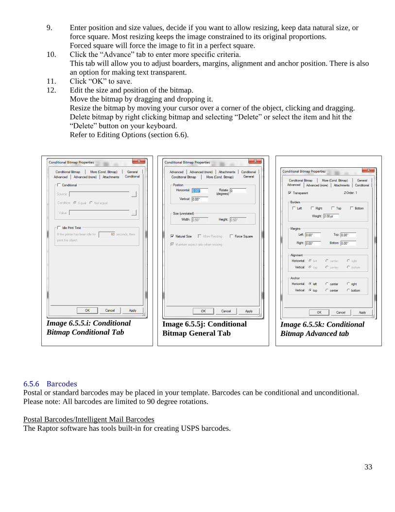
9. Enter position and size values, decide if you want to allow resizing, keep data natural size, or
force square. Most resizing keeps the image constrained to its original proportions.
Forced square will force the image to fit in a perfect square.
10. Click the “Advance” tab to enter more specific criteria.
This tab will allow you to adjust boarders, margins, alignment and anchor position. There is also
an option for making text transparent.
11. Click “OK” to save.
12. Edit the size and position of the bitmap.
Move the bitmap by dragging and dropping it.
Resize the bitmap by moving your cursor over a corner of the object, clicking and dragging.
Delete bitmap by right clicking bitmap and selecting “Delete” or select the item and hit the
“Delete” button on your keyboard.
Refer to Editing Options (section 6.6).
6.5.6 Barcodes Postal or standard barcodes may be placed in your template. Barcodes can be conditional and unconditional.
Please note: All barcodes are limited to 90 degree rotations.
Postal Barcodes/Intelligent Mail Barcodes
The Raptor software has tools built-in for creating USPS barcodes.
Image 6.5.5.i: Conditional
Bitmap Conditional Tab
Image 6.5.5j: Conditional
Bitmap General Tab
Image 6.5.5k: Conditional
Bitmap Advanced tab
34
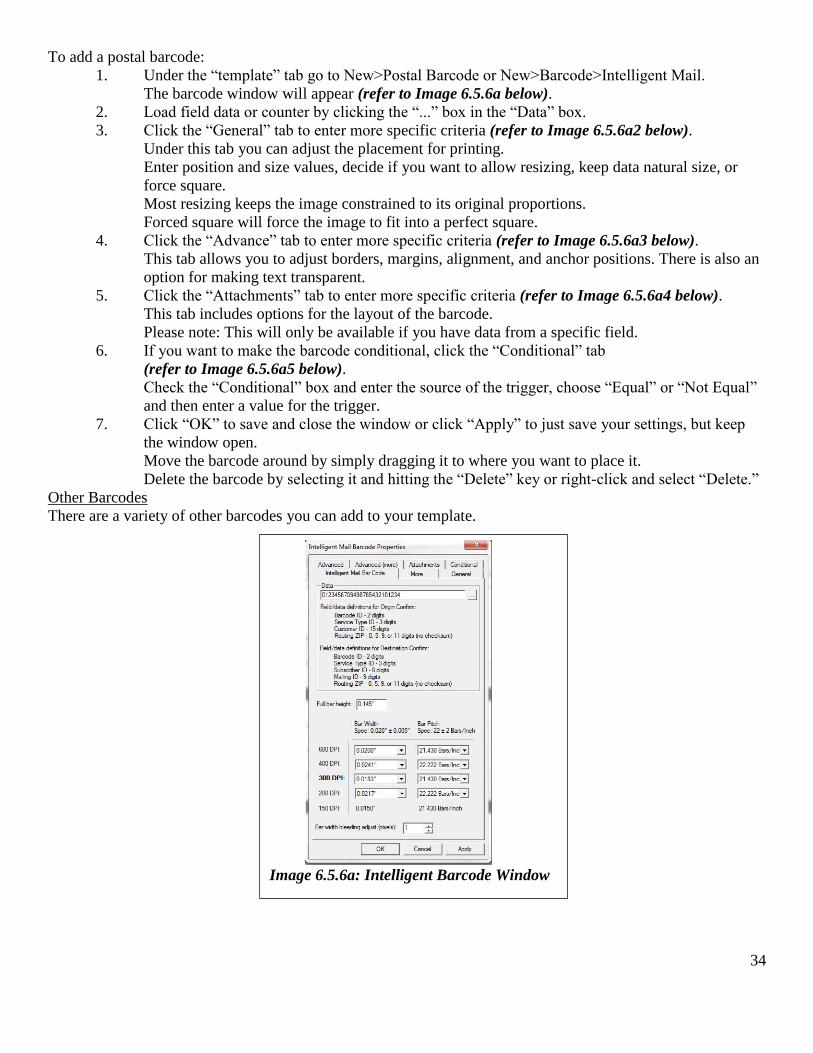
To add a postal barcode:
1. Under the “template” tab go to New>Postal Barcode or New>Barcode>Intelligent Mail.
The barcode window will appear (refer to Image 6.5.6a below).
2. Load field data or counter by clicking the “...” box in the “Data” box.
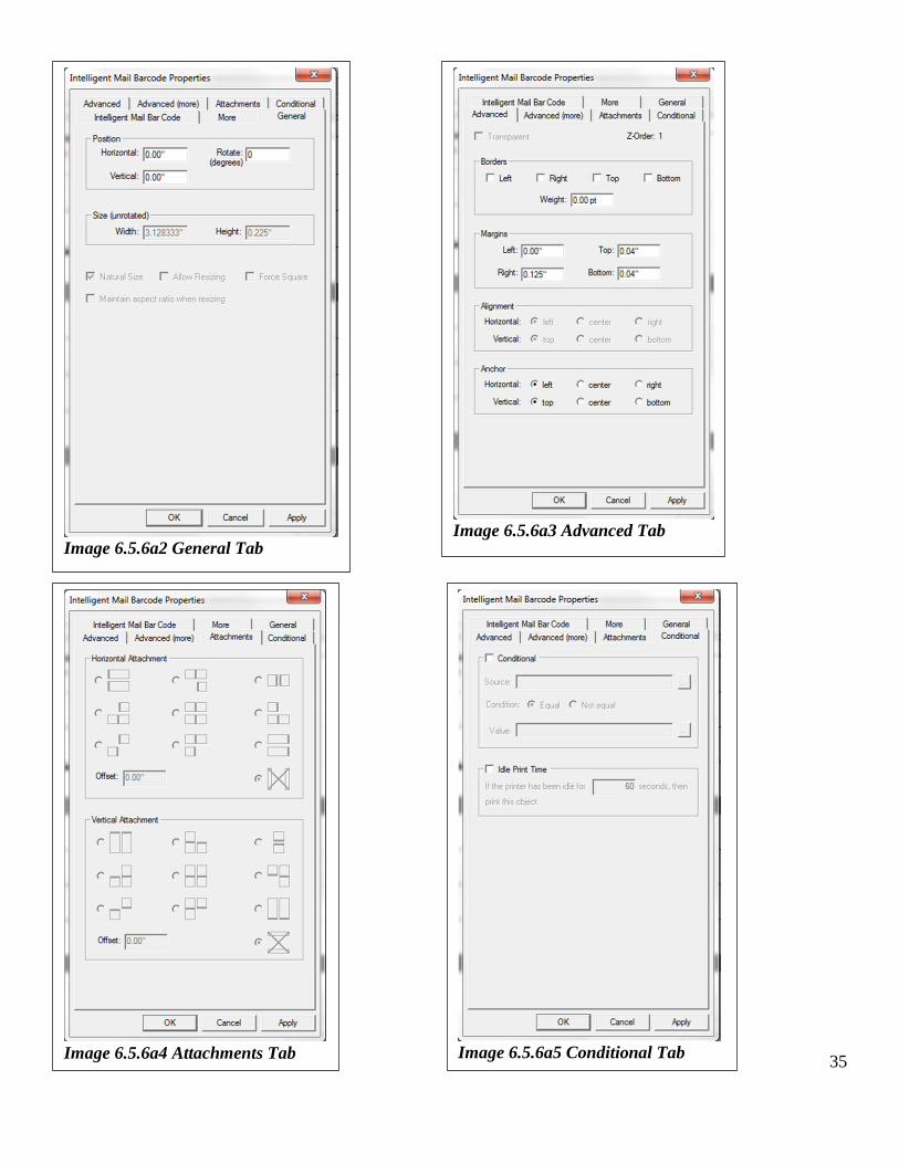
3. Click the “General” tab to enter more specific criteria (refer to Image 6.5.6a2 below).
Under this tab you can adjust the placement for printing.
Enter position and size values, decide if you want to allow resizing, keep data natural size, or
force square.
Most resizing keeps the image constrained to its original proportions.
Forced square will force the image to fit into a perfect square.
4. Click the “Advance” tab to enter more specific criteria (refer to Image 6.5.6a3 below).
This tab allows you to adjust borders, margins, alignment, and anchor positions. There is also an
option for making text transparent.
5. Click the “Attachments” tab to enter more specific criteria (refer to Image 6.5.6a4 below).
This tab includes options for the layout of the barcode.
Please note: This will only be available if you have data from a specific field.
6. If you want to make the barcode conditional, click the “Conditional” tab
(refer to Image 6.5.6a5 below).
Check the “Conditional” box and enter the source of the trigger, choose “Equal” or “Not Equal”
and then enter a value for the trigger.
7. Click “OK” to save and close the window or click “Apply” to just save your settings, but keep
the window open.
Move the barcode around by simply dragging it to where you want to place it.
Delete the barcode by selecting it and hitting the “Delete” key or right-click and select “Delete.”
Other Barcodes
There are a variety of other barcodes you can add to your template.
Image 6.5.6a: Intelligent Barcode Window
35
20
Image 6.5.6a2 General Tab
Image 6.5.6a3 Advanced Tab
Image 6.5.6a4 Attachments Tab
Image 6.5.6a5 Conditional Tab
36
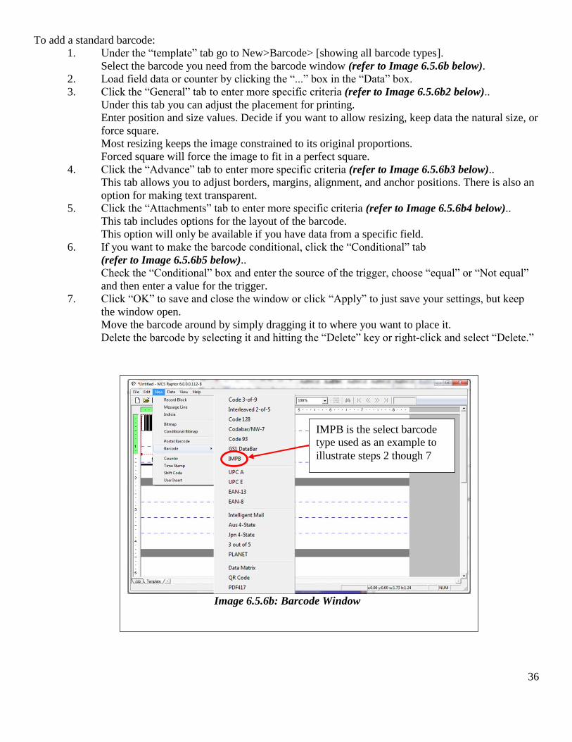
To add a standard barcode:
1. Under the “template” tab go to New>Barcode> [showing all barcode types].
Select the barcode you need from the barcode window (refer to Image 6.5.6b below).
2. Load field data or counter by clicking the “...” box in the “Data” box.
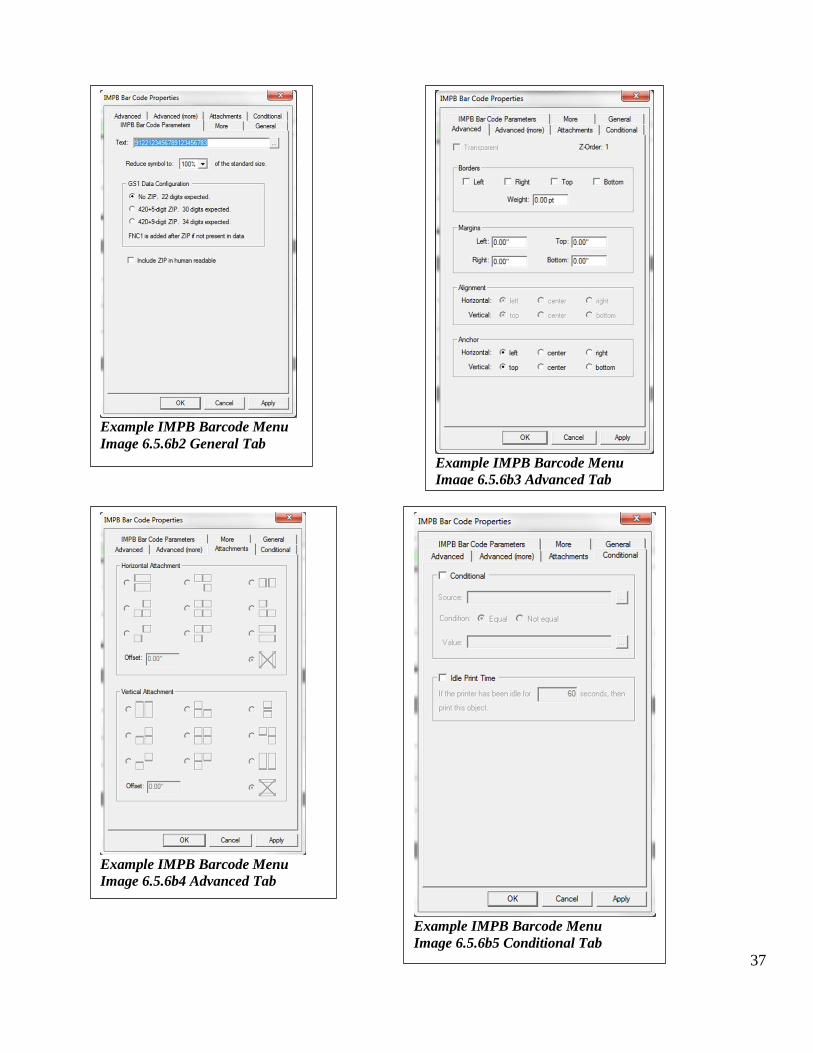
3. Click the “General” tab to enter more specific criteria (refer to Image 6.5.6b2 below)..
Under this tab you can adjust the placement for printing.
Enter position and size values. Decide if you want to allow resizing, keep data the natural size, or
force square.
Most resizing keeps the image constrained to its original proportions.
Forced square will force the image to fit in a perfect square.
4. Click the “Advance” tab to enter more specific criteria (refer to Image 6.5.6b3 below)..
This tab allows you to adjust borders, margins, alignment, and anchor positions. There is also an
option for making text transparent.
5. Click the “Attachments” tab to enter more specific criteria (refer to Image 6.5.6b4 below)..
This tab includes options for the layout of the barcode.
This option will only be available if you have data from a specific field.
6. If you want to make the barcode conditional, click the “Conditional” tab
(refer to Image 6.5.6b5 below)..
Check the “Conditional” box and enter the source of the trigger, choose “equal” or “Not equal”
and then enter a value for the trigger.
7. Click “OK” to save and close the window or click “Apply” to just save your settings, but keep
the window open.
Move the barcode around by simply dragging it to where you want to place it.
Delete the barcode by selecting it and hitting the “Delete” key or right-click and select “Delete.”
Image 6.5.6b: Barcode Window
IMPB is the select barcode
type used as an example to
illustrate steps 2 though 7
37
Example IMPB Barcode Menu
Image 6.5.6b2 General Tab Example IMPB Barcode Menu
Image 6.5.6b3 Advanced Tab
Example IMPB Barcode Menu
Image 6.5.6b4 Advanced Tab
Example IMPB Barcode Menu
Image 6.5.6b5 Conditional Tab
38
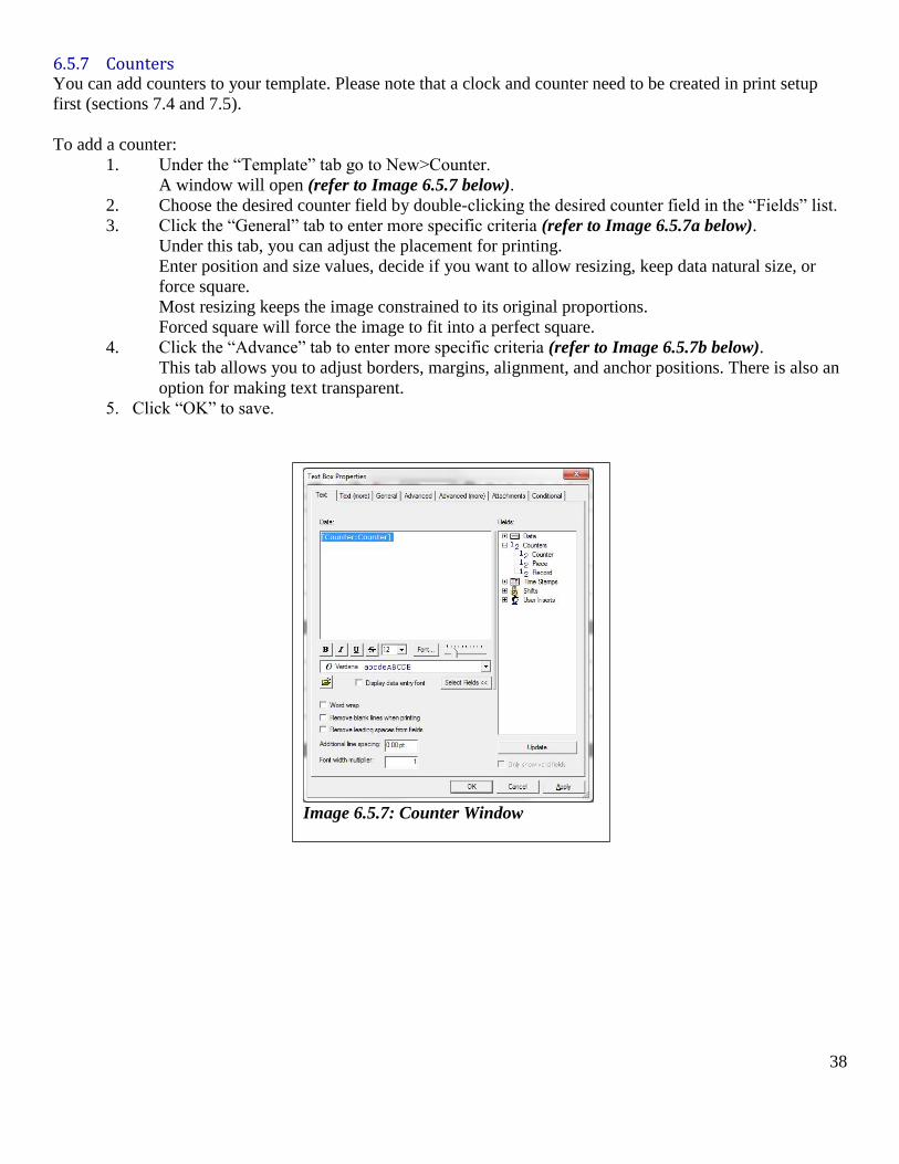
6.5.7 Counters You can add counters to your template. Please note that a clock and counter need to be created in print setup
first (sections 7.4 and 7.5).
To add a counter:
1. Under the “Template” tab go to New>Counter.
A window will open (refer to Image 6.5.7 below).
2. Choose the desired counter field by double-clicking the desired counter field in the “Fields” list.
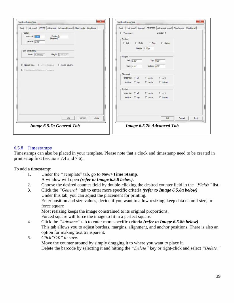
3. Click the “General” tab to enter more specific criteria (refer to Image 6.5.7a below).
Under this tab, you can adjust the placement for printing.
Enter position and size values, decide if you want to allow resizing, keep data natural size, or
force square.
Most resizing keeps the image constrained to its original proportions.
Forced square will force the image to fit into a perfect square.
4. Click the “Advance” tab to enter more specific criteria (refer to Image 6.5.7b below).
This tab allows you to adjust borders, margins, alignment, and anchor positions. There is also an
option for making text transparent.
5. Click “OK” to save.
Image 6.5.7: Counter Window
39
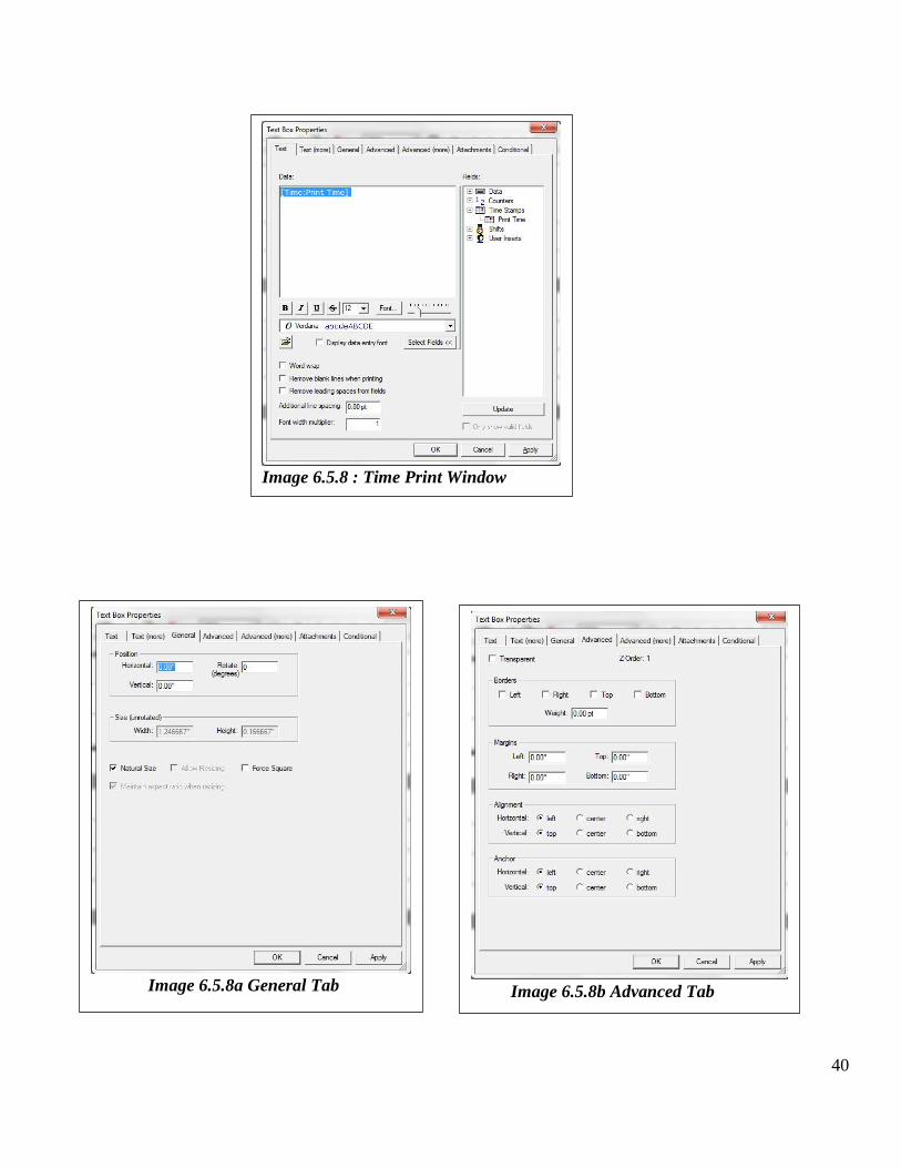
6.5.8 Timestamps Timestamps can also be placed in your template. Please note that a clock and timestamp need to be created in
print setup first (sections 7.4 and 7.6).
To add a timestamp:
1. Under the “Template” tab, go to New>Time Stamp.
A window will open (refer to Image 6.5.8 below).
2. Choose the desired counter field by double-clicking the desired counter field in the “Fields” list.
3. Click the “General” tab to enter more specific criteria (refer to Image 6.5.8a below).
Under this tab, you can adjust the placement for printing.
Enter position and size values, decide if you want to allow resizing, keep data natural size, or
force square
Most resizing keeps the image constrained to its original proportions.
Forced square will force the image to fit in a perfect square.
4. Click the “Advance” tab to enter more specific criteria (refer to Image 6.5.8b below).
This tab allows you to adjust borders, margins, alignment, and anchor positions. There is also an
option for making text transparent.
5. Click “OK” to save.
Move the counter around by simply dragging it to where you want to place it.
Delete the barcode by selecting it and hitting the “Delete” key or right-click and select “Delete.”
Image 6.5.7a General Tab
Image 6.5.7b Advanced Tab
40
Image 6.5.8 : Time Print Window
Image 6.5.8a General Tab
Image 6.5.8b Advanced Tab
41
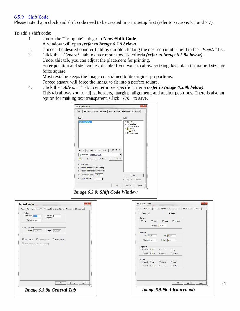
6.5.9 Shift Code Please note that a clock and shift code need to be created in print setup first (refer to sections 7.4 and 7.7).
To add a shift code:
1. Under the “Template” tab go to New>Shift Code.
A window will open (refer to Image 6.5.9 below).
2. Choose the desired counter field by double-clicking the desired counter field in the “Fields” list.
3. Click the “General” tab to enter more specific criteria (refer to Image 6.5.9a below).
Under this tab, you can adjust the placement for printing.
Enter position and size values, decide if you want to allow resizing, keep data the natural size, or
force square
Most resizing keeps the image constrained to its original proportions.
Forced square will force the image to fit into a perfect square.
4. Click the “Advance” tab to enter more specific criteria (refer to Image 6.5.9b below).
This tab allows you to adjust borders, margins, alignment, and anchor positions. There is also an
option for making text transparent. Click “OK” to save.
Image 6.5.9: Shift Code Window
Image 6.5.9a General Tab
Image 6.5.9b Advanced tab
42
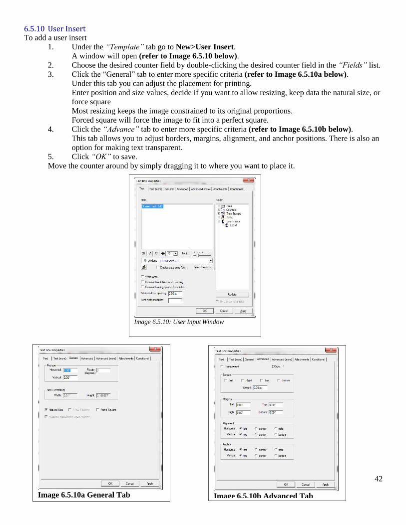
6.5.10 User Insert To add a user insert
1. Under the “Template” tab go to New>User Insert.
A window will open (refer to Image 6.5.10 below).
2. Choose the desired counter field by double-clicking the desired counter field in the “Fields” list.
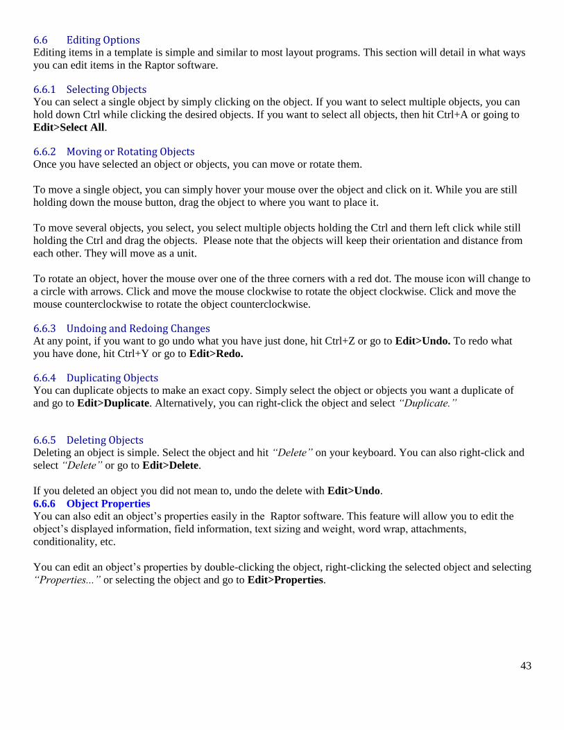
3. Click the “General” tab to enter more specific criteria (refer to Image 6.5.10a below).
Under this tab you can adjust the placement for printing.
Enter position and size values, decide if you want to allow resizing, keep data the natural size, or
force square
Most resizing keeps the image constrained to its original proportions.
Forced square will force the image to fit into a perfect square.
4. Click the “Advance” tab to enter more specific criteria (refer to Image 6.5.10b below).
This tab allows you to adjust borders, margins, alignment, and anchor positions. There is also an
option for making text transparent.
5. Click “OK” to save.
Move the counter around by simply dragging it to where you want to place it.
Image 6.5.10: User Input Window
Image 6.5.10a General Tab
Image 6.5.10b Advanced Tab
43
6.6 Editing Options Editing items in a template is simple and similar to most layout programs. This section will detail in what ways
you can edit items in the Raptor software.
6.6.1 Selecting Objects You can select a single object by simply clicking on the object. If you want to select multiple objects, you can
hold down Ctrl while clicking the desired objects. If you want to select all objects, then hit Ctrl+A or going to
Edit>Select All.
6.6.2 Moving or Rotating Objects Once you have selected an object or objects, you can move or rotate them.
To move a single object, you can simply hover your mouse over the object and click on it. While you are still
holding down the mouse button, drag the object to where you want to place it.
To move several objects, you select, you select multiple objects holding the Ctrl and thern left click while still
holding the Ctrl and drag the objects. Please note that the objects will keep their orientation and distance from
each other. They will move as a unit.
To rotate an object, hover the mouse over one of the three corners with a red dot. The mouse icon will change to
a circle with arrows. Click and move the mouse clockwise to rotate the object clockwise. Click and move the
mouse counterclockwise to rotate the object counterclockwise.
6.6.3 Undoing and Redoing Changes At any point, if you want to go undo what you have just done, hit Ctrl+Z or go to Edit>Undo. To redo what
you have done, hit Ctrl+Y or go to Edit>Redo.
6.6.4 Duplicating Objects You can duplicate objects to make an exact copy. Simply select the object or objects you want a duplicate of
and go to Edit>Duplicate. Alternatively, you can right-click the object and select “Duplicate.”
6.6.5 Deleting Objects Deleting an object is simple. Select the object and hit “Delete” on your keyboard. You can also right-click and
select “Delete” or go to Edit>Delete.
If you deleted an object you did not mean to, undo the delete with Edit>Undo.
6.6.6 Object Properties
You can also edit an object’s properties easily in the Raptor software. This feature will allow you to edit the
object’s displayed information, field information, text sizing and weight, word wrap, attachments,
conditionality, etc.
You can edit an object’s properties by double-clicking the object, right-clicking the selected object and selecting
“Properties...” or selecting the object and go to Edit>Properties.
44
6.6.7 Aligning Objects You can have the Raptor software align objects for you to make sure they are on the same line or edge.
There are many types of alignment the program can do for you. You can choose to align items on the left, right,
top, bottom, horizontal center, vertical center, and side by side.
To align objects:
1. Select the objects you wish to align.
2. Use Ctrl+Left-Click to select multiple objects.
3. Go to Edit>Align>[desired alignment type].
Remember, you can undo unwanted changes with Ctrl+Z or go to Edit>Undo.
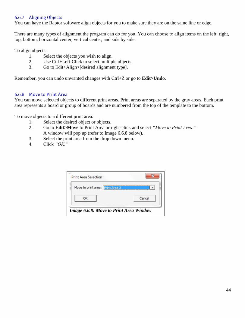
6.6.8 Move to Print Area You can move selected objects to different print areas. Print areas are separated by the gray areas. Each print
area represents a board or group of boards and are numbered from the top of the template to the bottom.
To move objects to a different print area:
1. Select the desired object or objects.
2. Go to Edit>Move to Print Area or right-click and select “Move to Print Area.”
A window will pop up (refer to Image 6.6.8 below).
3. Select the print area from the drop down menu.
4. Click “OK.”
Image 6.6.8: Move to Print Area Window
45
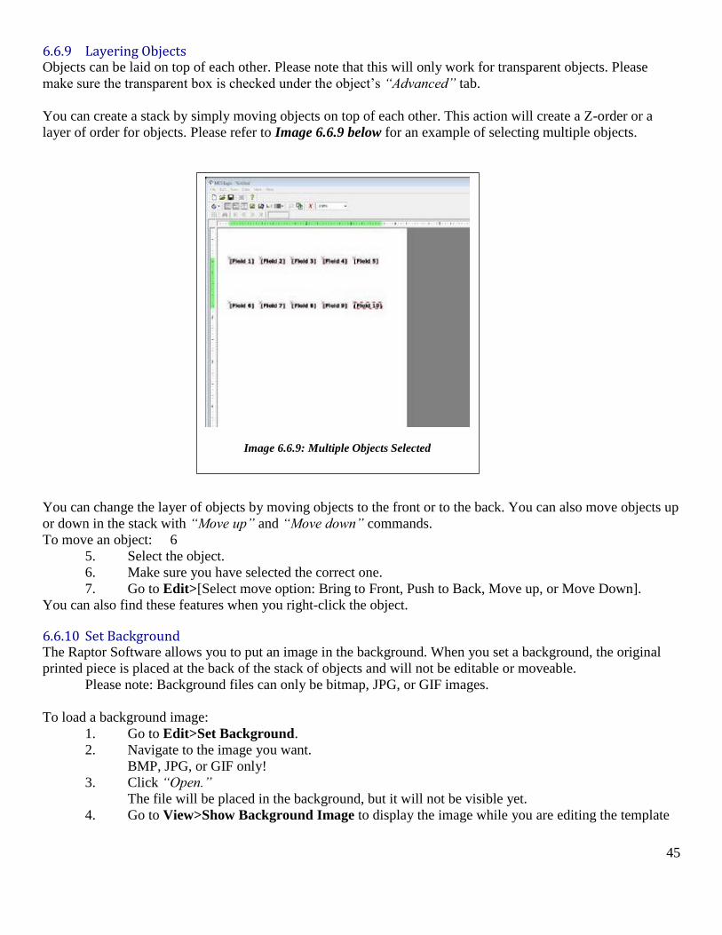
6.6.9 Layering Objects Objects can be laid on top of each other. Please note that this will only work for transparent objects. Please
make sure the transparent box is checked under the object’s “Advanced” tab.
You can create a stack by simply moving objects on top of each other. This action will create a Z-order or a
layer of order for objects. Please refer to Image 6.6.9 below for an example of selecting multiple objects.
You can change the layer of objects by moving objects to the front or to the back. You can also move objects up
or down in the stack with “Move up” and “Move down” commands.
To move an object: 6
5. Select the object.
6. Make sure you have selected the correct one.
7. Go to Edit>[Select move option: Bring to Front, Push to Back, Move up, or Move Down].
You can also find these features when you right-click the object.
6.6.10 Set Background The Raptor Software allows you to put an image in the background. When you set a background, the original
printed piece is placed at the back of the stack of objects and will not be editable or moveable.
Please note: Background files can only be bitmap, JPG, or GIF images.
To load a background image:
1. Go to Edit>Set Background.
2. Navigate to the image you want.
BMP, JPG, or GIF only!
3. Click “Open.”
The file will be placed in the background, but it will not be visible yet.
4. Go to View>Show Background Image to display the image while you are editing the template
Image 6.6.9: Multiple Objects Selected
46
6.6.11 Scanning Data While laying out your template, it may be necessary to space items according to your longest or largest entry.
The Raptor Software has a tool for this process.
To scan data:
1. Click the desired object for spacing.
2. Go to Edit>Scan Data.
The longest record will be displayed in the record block.
If you do not see the longest record, make sure the “show record data” button is selected on the
toolbar.
6.7 Viewing Options A variety of options are available under the “View” menu. This manual has already mentioned you can show
record data and show background images. Under the view menu, you can also opt to see guidelines, show
colors, show zoom level, show anchor points, show Z-order (layered order of objects), show attachments and
dock markers, and show pen colors (spot color editing).
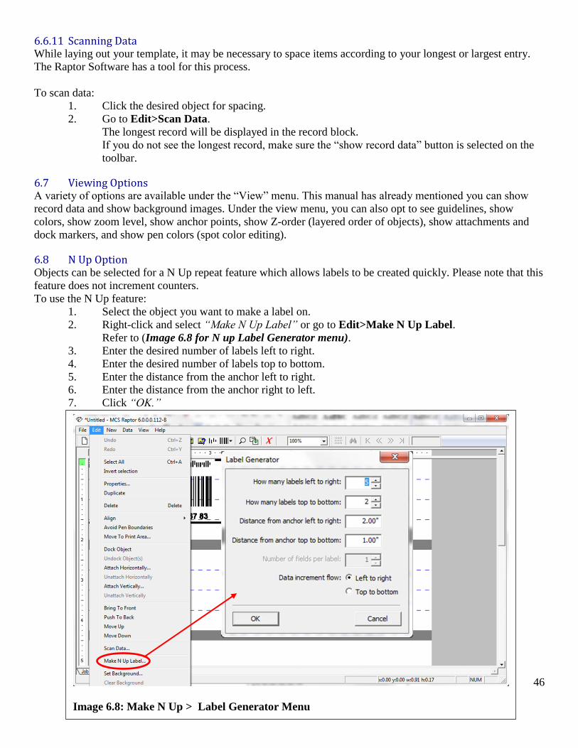
6.8 N Up Option Objects can be selected for a N Up repeat feature which allows labels to be created quickly. Please note that this
feature does not increment counters.
To use the N Up feature:
1. Select the object you want to make a label on.
2. Right-click and select “Make N Up Label” or go to Edit>Make N Up Label.
Refer to (Image 6.8 for N up Label Generator menu).
3. Enter the desired number of labels left to right.
4. Enter the desired number of labels top to bottom.
5. Enter the distance from the anchor left to right.
6. Enter the distance from the anchor right to left.
7. Click “OK.”
Image 6.8: Make N Up > Label Generator Menu

47
6.9 Print Proof You can choose to print to a regular office printer to review the template layout. This type of printing will not
reflect any job settings, just the layout.
To print a print proof:
1. Go to Edit>Print Proof.
A window will pop up that will allow you to select specific records or scale the proof.
2. Edit printing options.
3. Click “Print.”
4. Select desired printer.
5. Click “OK.”

48
Section Seven
Print Setup
49
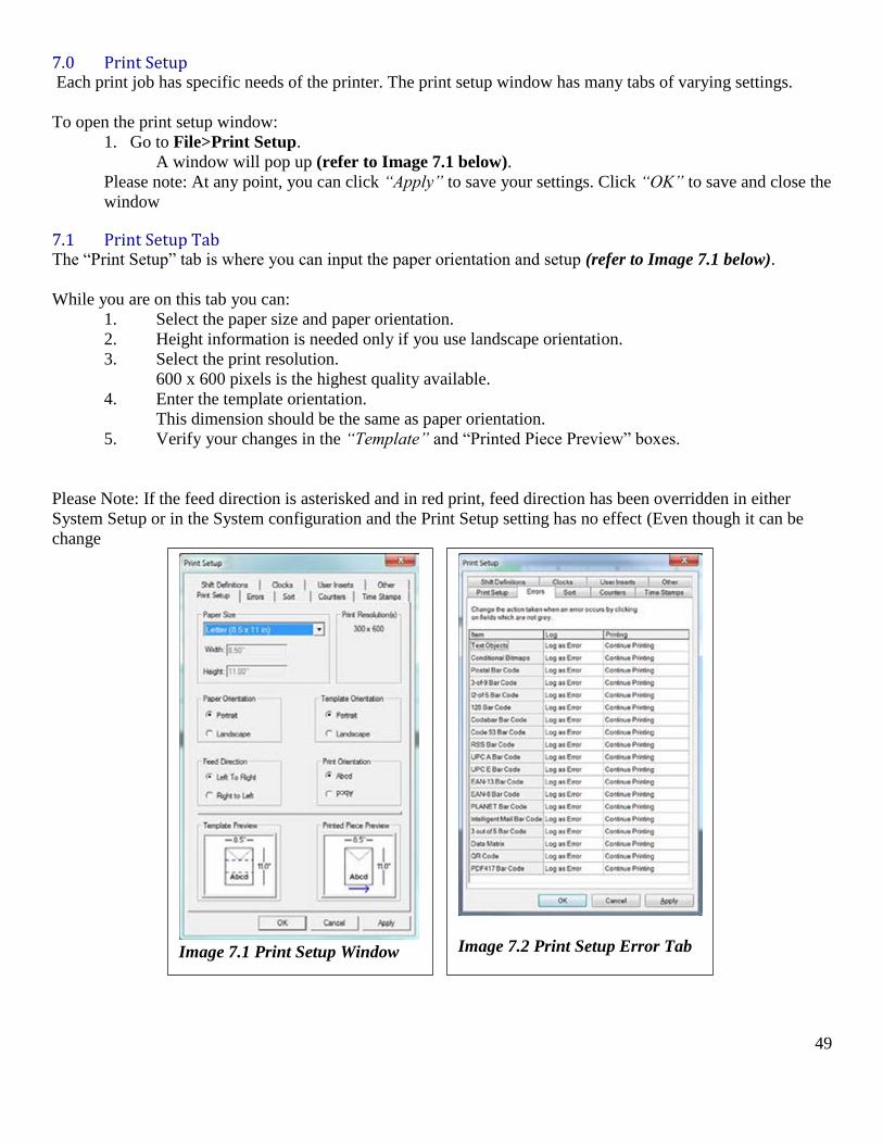
7.0 Print Setup Each print job has specific needs of the printer. The print setup window has many tabs of varying settings.
To open the print setup window:
1. Go to File>Print Setup.
A window will pop up (refer to Image 7.1 below).
Please note: At any point, you can click “Apply” to save your settings. Click “OK” to save and close the
window
7.1 Print Setup Tab The “Print Setup” tab is where you can input the paper orientation and setup (refer to Image 7.1 below).
While you are on this tab you can:
1. Select the paper size and paper orientation.
2. Height information is needed only if you use landscape orientation.
3. Select the print resolution.
600 x 600 pixels is the highest quality available.
4. Enter the template orientation.
This dimension should be the same as paper orientation.
5. Verify your changes in the “Template” and “Printed Piece Preview” boxes.
Please Note: If the feed direction is asterisked and in red print, feed direction has been overridden in either
System Setup or in the System configuration and the Print Setup setting has no effect (Even though it can be
change
Image 7.1 Print Setup Window
Image 7.2 Print Setup Error Tab
50
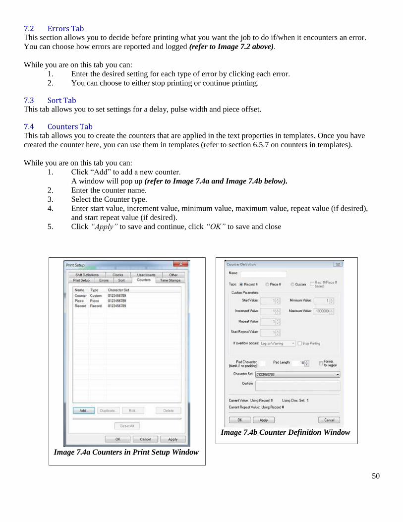
7.2 Errors Tab This section allows you to decide before printing what you want the job to do if/when it encounters an error.
You can choose how errors are reported and logged (refer to Image 7.2 above).
While you are on this tab you can:
1. Enter the desired setting for each type of error by clicking each error.
2. You can choose to either stop printing or continue printing.
7.3 Sort Tab This tab allows you to set settings for a delay, pulse width and piece offset.
7.4 Counters Tab This tab allows you to create the counters that are applied in the text properties in templates. Once you have
created the counter here, you can use them in templates (refer to section 6.5.7 on counters in templates).
While you are on this tab you can:
1. Click “Add” to add a new counter.
A window will pop up (refer to Image 7.4a and Image 7.4b below).
2. Enter the counter name.
3. Select the Counter type.
4. Enter start value, increment value, minimum value, maximum value, repeat value (if desired),
and start repeat value (if desired).
5. Click “Apply” to save and continue, click “OK” to save and close
Image 7.4a Counters in Print Setup Window
Image 7.4b Counter Definition Window
51
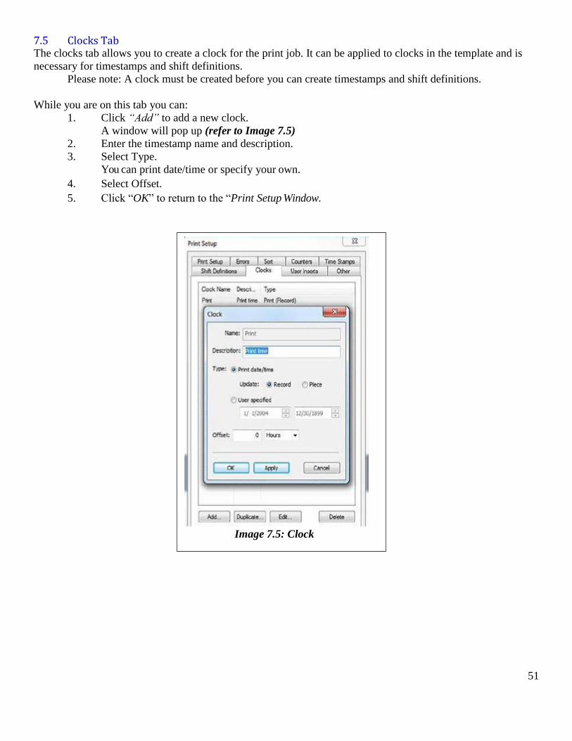
7.5 Clocks Tab The clocks tab allows you to create a clock for the print job. It can be applied to clocks in the template and is
necessary for timestamps and shift definitions.
Please note: A clock must be created before you can create timestamps and shift definitions.
While you are on this tab you can:
1. Click “Add” to add a new clock.
A window will pop up (refer to Image 7.5)
2. Enter the timestamp name and description.
3. Select Type.
You can print date/time or specify your own.
4. Select Offset.
5. Click “OK” to return to the “Print Setup Window.
Image 7.5: Clock
52
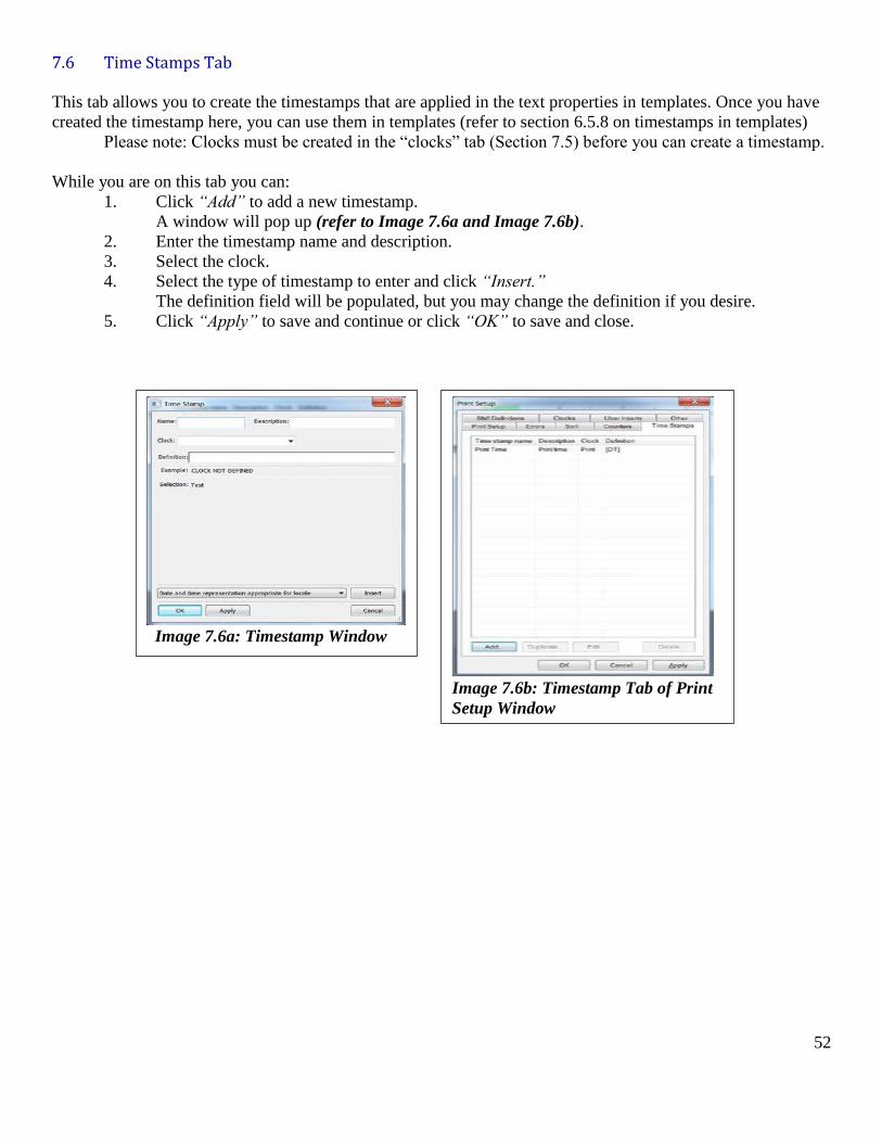
7.6 Time Stamps Tab
This tab allows you to create the timestamps that are applied in the text properties in templates. Once you have
created the timestamp here, you can use them in templates (refer to section 6.5.8 on timestamps in templates)
Please note: Clocks must be created in the “clocks” tab (Section 7.5) before you can create a timestamp.
While you are on this tab you can:
1. Click “Add” to add a new timestamp.
A window will pop up (refer to Image 7.6a and Image 7.6b).
2. Enter the timestamp name and description.
3. Select the clock.
4. Select the type of timestamp to enter and click “Insert.”
The definition field will be populated, but you may change the definition if you desire.
5. Click “Apply” to save and continue or click “OK” to save and close.
Image 7.6a: Timestamp Window
Image 7.6b: Timestamp Tab of Print
Setup Window
53
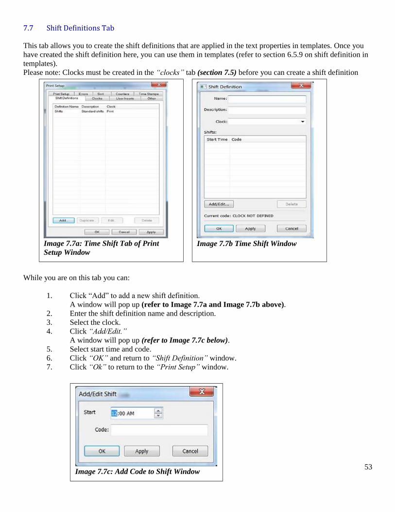
7.7 Shift Definitions Tab
This tab allows you to create the shift definitions that are applied in the text properties in templates. Once you
have created the shift definition here, you can use them in templates (refer to section 6.5.9 on shift definition in
templates).
Please note: Clocks must be created in the “clocks” tab (section 7.5) before you can create a shift definition
While you are on this tab you can:
1. Click “Add” to add a new shift definition.
A window will pop up (refer to Image 7.7a and Image 7.7b above).
2. Enter the shift definition name and description.
3. Select the clock.
4. Click “Add/Edit.”
A window will pop up (refer to Image 7.7c below).
5. Select start time and code.
6. Click “OK” and return to “Shift Definition” window.
7. Click “Ok” to return to the “Print Setup” window.
Image 7.7a: Time Shift Tab of Print
Setup Window
Image 7.7b Time Shift Window
Image 7.7c: Add Code to Shift Window
54
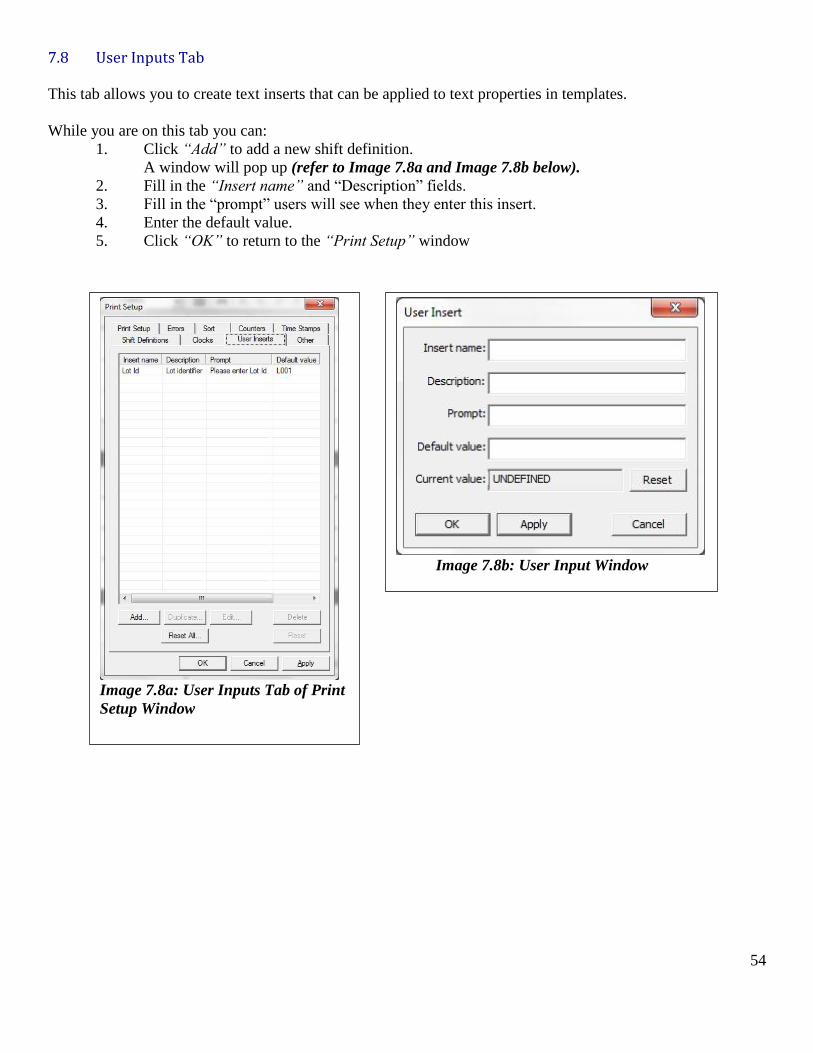
7.8 User Inputs Tab
This tab allows you to create text inserts that can be applied to text properties in templates.
While you are on this tab you can:
1. Click “Add” to add a new shift definition.
A window will pop up (refer to Image 7.8a and Image 7.8b below).
2. Fill in the “Insert name” and “Description” fields.
3. Fill in the “prompt” users will see when they enter this insert.
4. Enter the default value.
5. Click “OK” to return to the “Print Setup” window
Image 7.8a: User Inputs Tab of Print
Setup Window
Image 7.8b: User Input Window
55
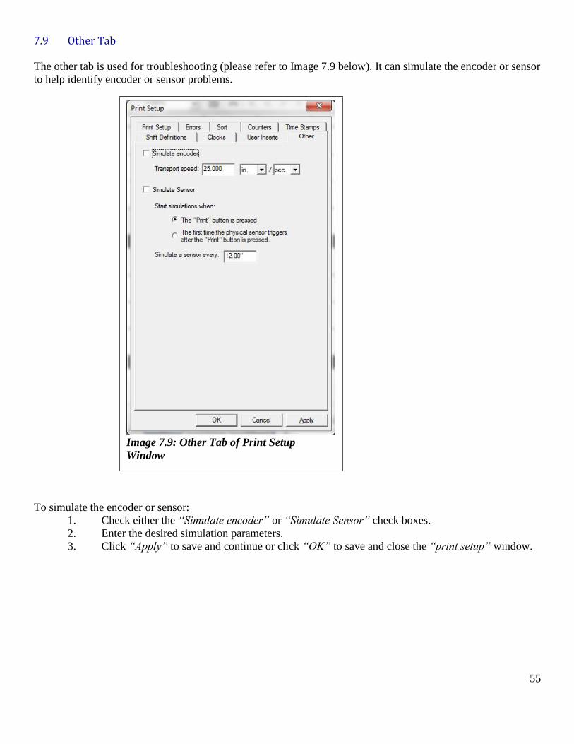
7.9 Other Tab
The other tab is used for troubleshooting (please refer to Image 7.9 below). It can simulate the encoder or sensor
to help identify encoder or sensor problems.
To simulate the encoder or sensor:
1. Check either the “Simulate encoder” or “Simulate Sensor” check boxes.
2. Enter the desired simulation parameters.
3. Click “Apply” to save and continue or click “OK” to save and close the “print setup” window.
Image 7.9: Other Tab of Print Setup
Window

56
Section Eight
Printing
57
8.0 Printing
In the Raptor Software, jobs are the control center for printing. The job window shows a variety of status
information and allows you to print the print job.
A job consists of data, a template, and all print and system settings. Creating a job is described in this section.
Please refer to Section 7 on Templates and Section 8 on Print Setup.
8.1 Creating, Opening, and Saving Jobs With the Raptor software, you can create a new job, open an existing job, and save a job. Job file names appear
in red if they have not been saved and an asterisk (*) will appear in the title bar if there are any unsaved
changes.
8.1.1 Creating Jobs To open a new job:
1. Make sure you are on the “Job” tab in the tab selection window.
2. Go to File>New Job.
3. If an existing job is open, you will be asked if you want to save the previous job, open a new job
without saving, or cancel.
8.1.2 Opening Existing Jobs To open an existing job:
1. Make sure you are on the “Job” tab in the tab selection window.
2. Go to File>Open or select the “Open” icon in the toolbar.
If an existing job is open you will be asked if you want to save the previous job, open a new job
without saving, or cancel.
8.1.3 Saving Jobs To save a job:
1. Go to File>Save Job or click the “Save” icon in the toolbar.
2. Provide a name for the job and click “Save.”
Please note: You can also use the “Save As” feature to save the job under a new name. All the
current changes will be made to the new save as opposed to the previous save.
8.2 Printing Jobs The entire process for using jobs is as follows:
1. Make sure you are on the “Job” tab in the tab selection window.
2. Go to File>New Job or load a previous job by going to File>Open.
If an existing job is open, you will be asked if you want to save the previous job, open a new job
without saving, or cancel.
3. Import Data (Refer to Section 5 on Importing Data).
4. Create a template (Refer to Section 6 on Templates).
5. Specify printer settings (Refer to Section 7 on Printer Settings).
6. Go to File>Save Job or click the “Save” icon in the toolbar.
7. Provide a name for the job and click “Save.”
You can now print the job by going to File>Print.
Please note: When you are printing a job, all menu items will become unavailable except for “Stop Printing.”
58
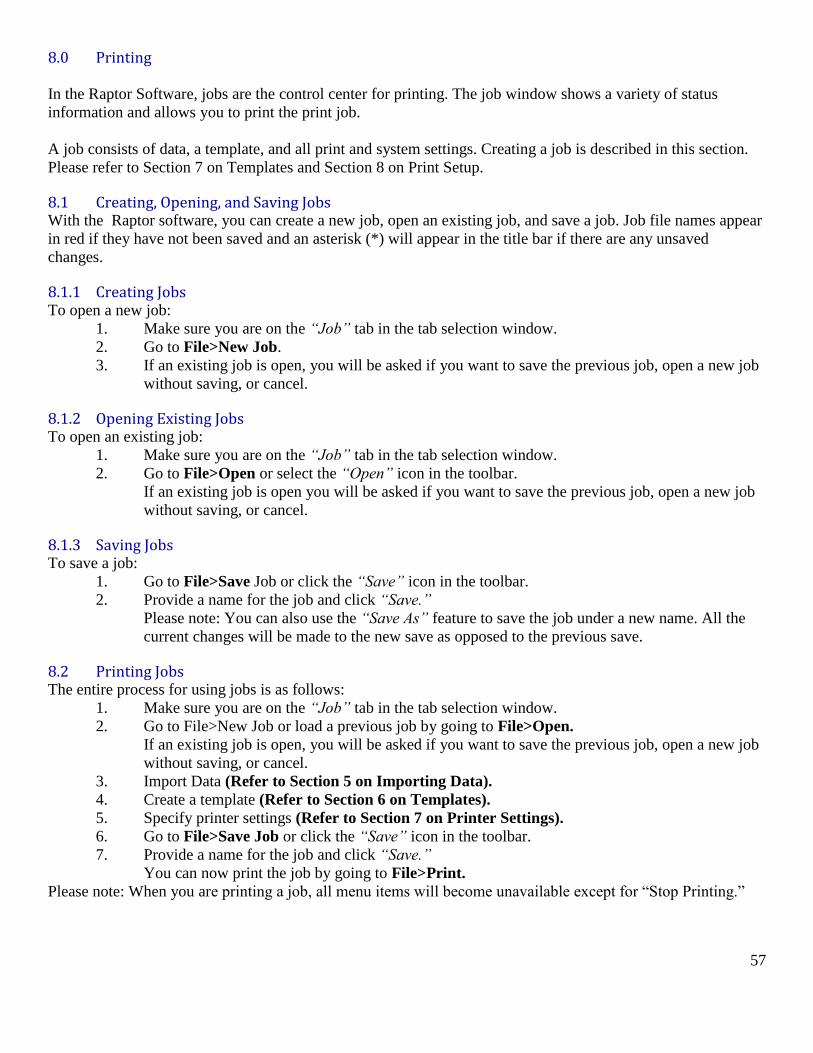
8.3 Checking Print Status The window displays current printing status in a large status box. The status box will display red when there is a
problem or when connected but idle. The status box will display yellow if printing and green if printing was
completed successfully.
Image 8.3a: Printing Display Shows Printer is in the Process of Printing
Image 8.3b: Printing Display Shows the Ink is Low and Print Speed is Bad
Image 8.3c: Printing Display Shows the Ink is Low and the Print Speed is Good
59
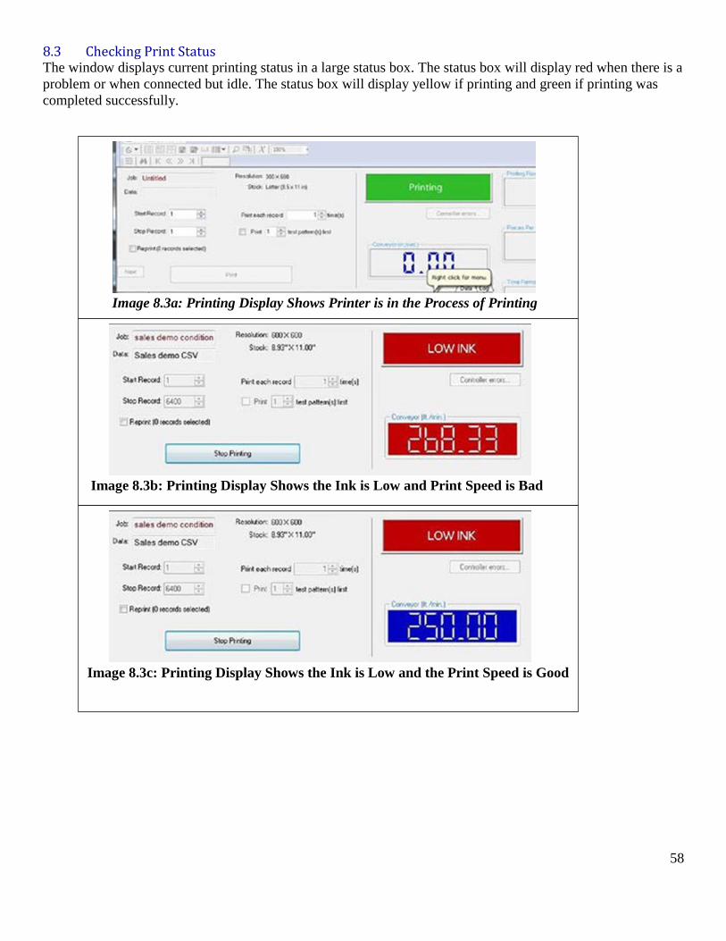
8.3.1 Viewing the Job Log The job log displays a variety of information about the printer and the job. You can view the job log by
selecting the “Job” tab and then the “Log” tab.
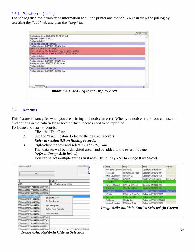
8.4 Reprints
This feature is handy for when you are printing and notice an error. When you notice errors, you can use the
find options in the data fields to locate which records need to be reprinted
To locate and reprint records:
1. Click the “Data” tab.
2. Use the “Find” feature to locate the desired record(s).
Refer to section 5.5 on finding records.
3. Right-click the row and select “Add to Reprints.”
That data set will be highlighted green and be added to the re-print queue
(refer to Image 8.4b below).
You can select multiple entries first with Ctrl+click (refer to Image 8.4a below).
Image 8.3.1: Job Log in the Display Area
Image 8.4a: Right-click Menu Selection
Image 8.4b: Multiple Entries Selected (in Green)
60
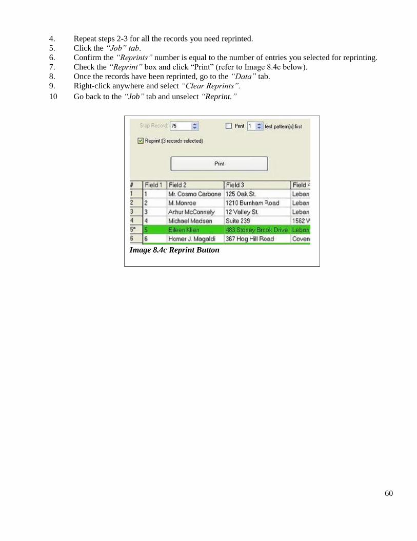
4. Repeat steps 2-3 for all the records you need reprinted.
5. Click the “Job” tab.
6. Confirm the “Reprints” number is equal to the number of entries you selected for reprinting.
7. Check the “Reprint” box and click “Print” (refer to Image 8.4c below).
8. Once the records have been reprinted, go to the “Data” tab.
9. Right-click anywhere and select “Clear Reprints”.
10 Go back to the “Job” tab and unselect “Reprint.”
Image 8.4c Reprint Button

61
Section Nine
Pen Maintenance
62
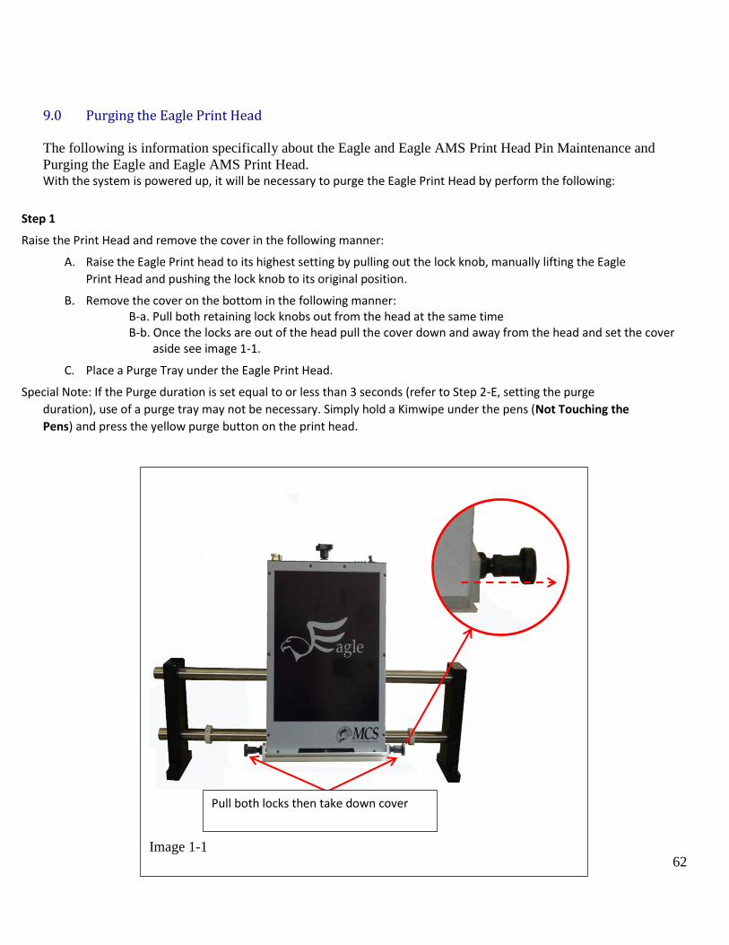
9.0 Purging the Eagle Print Head
The following is information specifically about the Eagle and Eagle AMS Print Head Pin Maintenance and
Purging the Eagle and Eagle AMS Print Head. With the system is powered up, it will be necessary to purge the Eagle Print Head by perform the following:
Step 1
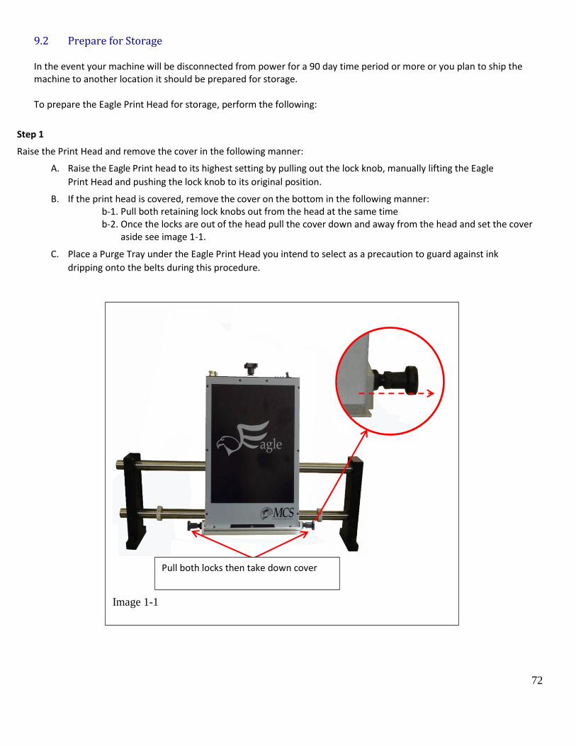
Raise the Print Head and remove the cover in the following manner:
A. Raise the Eagle Print head to its highest setting by pulling out the lock knob, manually lifting the Eagle
Print Head and pushing the lock knob to its original position.
B. Remove the cover on the bottom in the following manner: B-a. Pull both retaining lock knobs out from the head at the same time B-b. Once the locks are out of the head pull the cover down and away from the head and set the cover aside see image 1-1.
C. Place a Purge Tray under the Eagle Print Head.
Special Note: If the Purge duration is set equal to or less than 3 seconds (refer to Step 2-E, setting the purge
duration), use of a purge tray may not be necessary. Simply hold a Kimwipe under the pens (Not Touching the
Pens) and press the yellow purge button on the print head.
Image 1-1
Pull both locks then take down cover
63
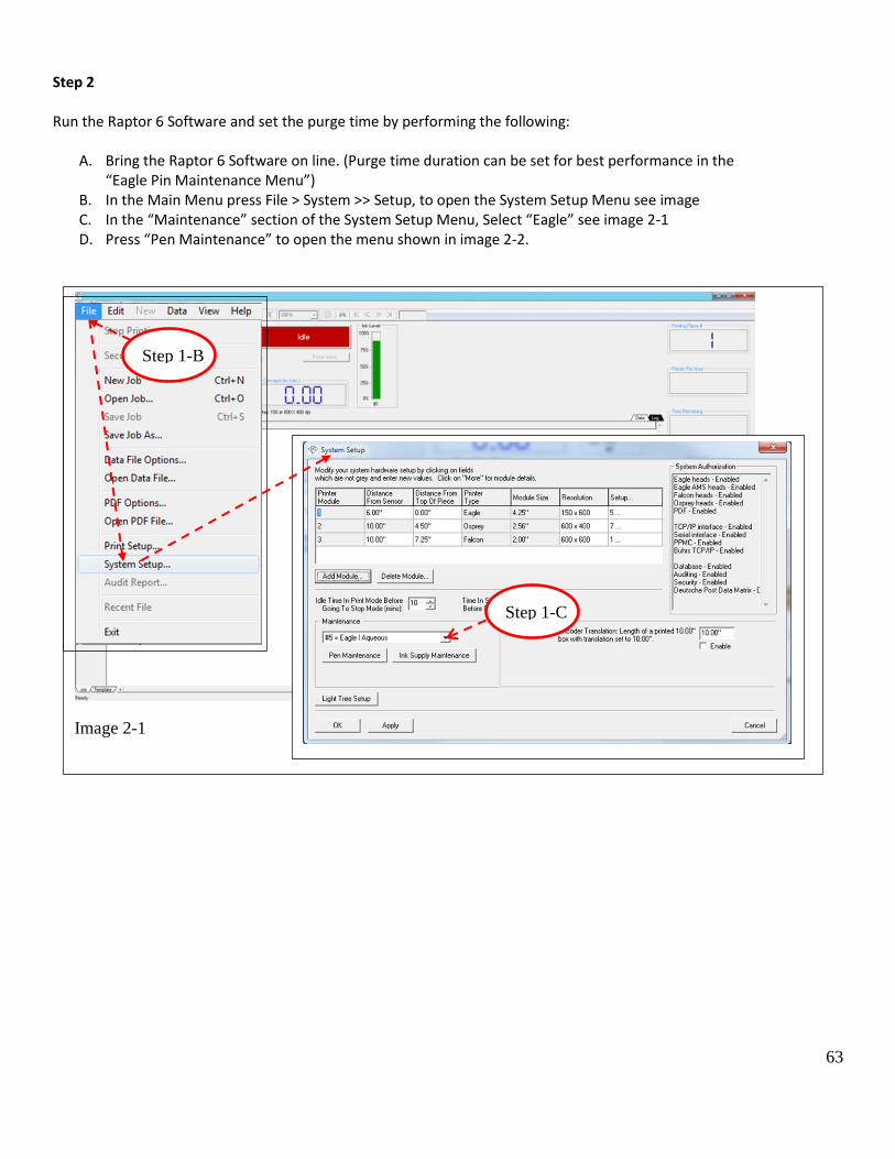
Step 2 Run the Raptor 6 Software and set the purge time by performing the following:
A. Bring the Raptor 6 Software on line. (Purge time duration can be set for best performance in the “Eagle Pin Maintenance Menu”)
B. In the Main Menu press File > System >> Setup, to open the System Setup Menu see image C. In the “Maintenance” section of the System Setup Menu, Select “Eagle” see image 2-1 D. Press “Pen Maintenance” to open the menu shown in image 2-2.
Image 2-1
Step 1-C
Step 1-B
64
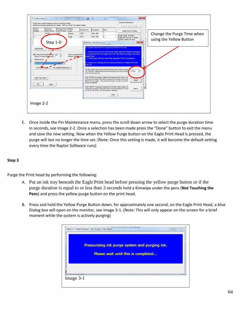
E. Once inside the Pin Maintenance menu, press the scroll down arrow to select the purge duration time
in seconds, see image 2-2. Once a selection has been made press the “Done” button to exit the menu
and save the new setting. Now when the Yellow Purge button on the Eagle Print Head is pressed, the
purge will last no longer the time set. (Note: Once this setting is made, it will become the default setting
every time the Raptor Software runs)
Step 3
Purge the Print head by performing the following:
A. Put an ink tray beneath the Eagle Print head before pressing the yellow purge button or if the
purge duration is equal to or less than 3 seconds hold a Kimwipe under the pens (Not Touching the
Pens) and press the yellow purge button on the print head.
B. Press and hold the Yellow Purge Button down, for approximately one second, on the Eagle Print Head, a blue Dialog box will open on the monitor, see image 3-1. (Note: This will only appear on the screen for a brief moment while the system is actively purging)
Image 3-1
Image 2-2
Change the Purge Time when using the Yellow Button
Step 1-D
65
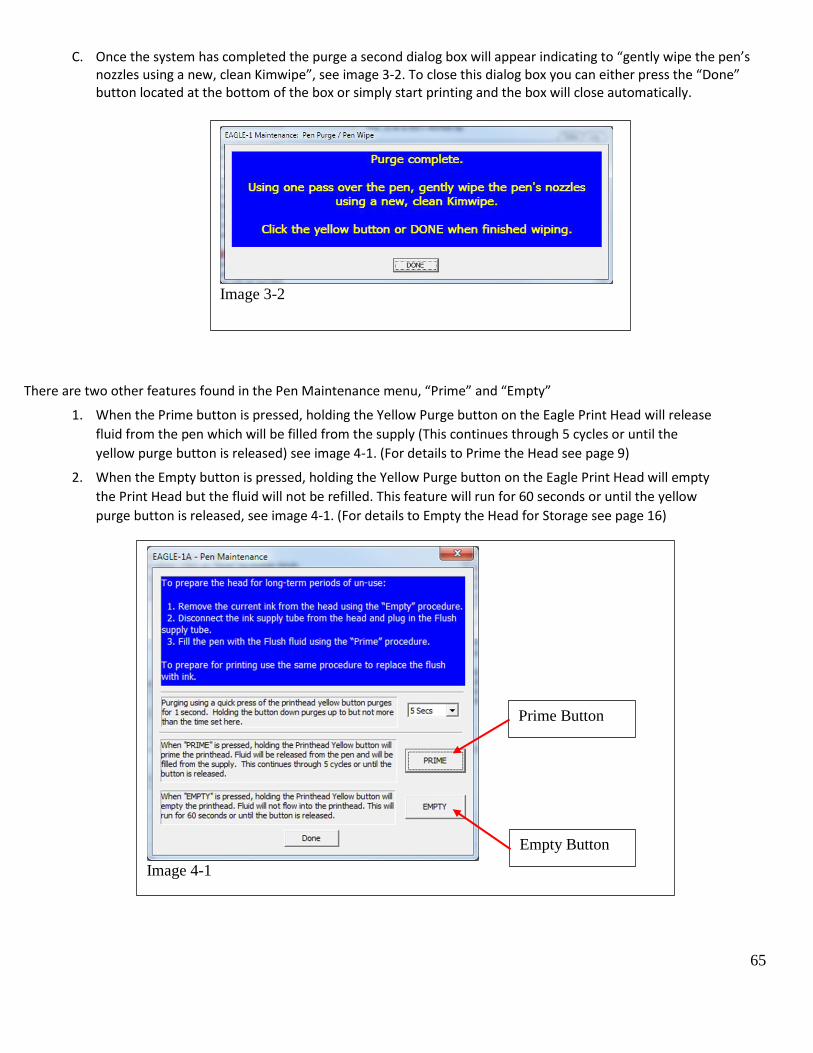
C. Once the system has completed the purge a second dialog box will appear indicating to “gently wipe the pen’s nozzles using a new, clean Kimwipe”, see image 3-2. To close this dialog box you can either press the “Done” button located at the bottom of the box or simply start printing and the box will close automatically.
There are two other features found in the Pen Maintenance menu, “Prime” and “Empty”
1. When the Prime button is pressed, holding the Yellow Purge button on the Eagle Print Head will release
fluid from the pen which will be filled from the supply (This continues through 5 cycles or until the
yellow purge button is released) see image 4-1. (For details to Prime the Head see page 9)
2. When the Empty button is pressed, holding the Yellow Purge button on the Eagle Print Head will empty
the Print Head but the fluid will not be refilled. This feature will run for 60 seconds or until the yellow
purge button is released, see image 4-1. (For details to Empty the Head for Storage see page 16)
Image 4-1
Prime Button
Empty Button
Image 3-2
66
9.1 Priming the Eagle Print Head
In the event air gets into the ink lines or ink foams from the pens during a purge, using the Prime feature will
move greater volumes of ink through the system and clear the lines more efficiently than performing multiple
purges.
To Prime the Print Head perform the following steps:
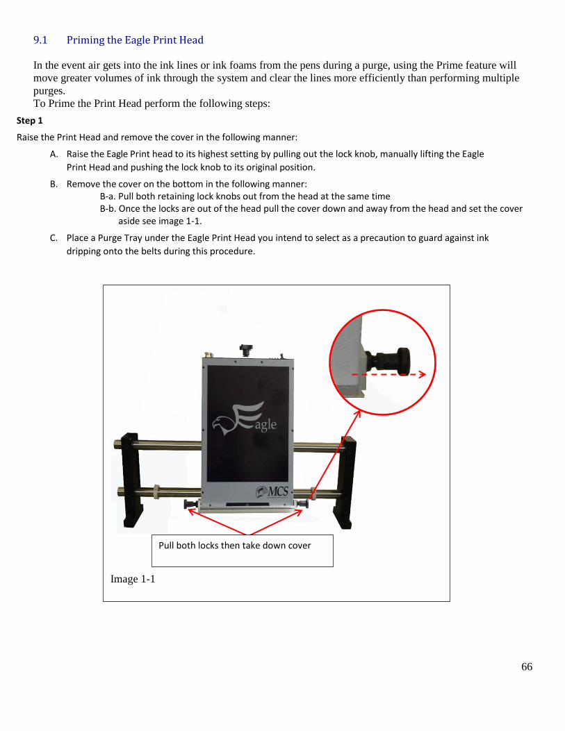
Step 1
Raise the Print Head and remove the cover in the following manner:
A. Raise the Eagle Print head to its highest setting by pulling out the lock knob, manually lifting the Eagle
Print Head and pushing the lock knob to its original position.
B. Remove the cover on the bottom in the following manner: B-a. Pull both retaining lock knobs out from the head at the same time B-b. Once the locks are out of the head pull the cover down and away from the head and set the cover aside see image 1-1.
C. Place a Purge Tray under the Eagle Print Head you intend to select as a precaution to guard against ink
dripping onto the belts during this procedure.
Image 1-1
Pull both locks then take down cover
67
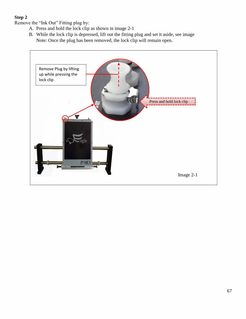
Step 2
Remove the “Ink Out” Fitting plug by:
A. Press and hold the lock clip as shown in image 2-1
B. While the lock clip is depressed, lift out the fitting plug and set it aside, see image
Note: Once the plug has been removed, the lock clip will remain open.
Image 2-1
Press and hold lock clip
Remove Plug by lifting up while pressing the lock clip
68
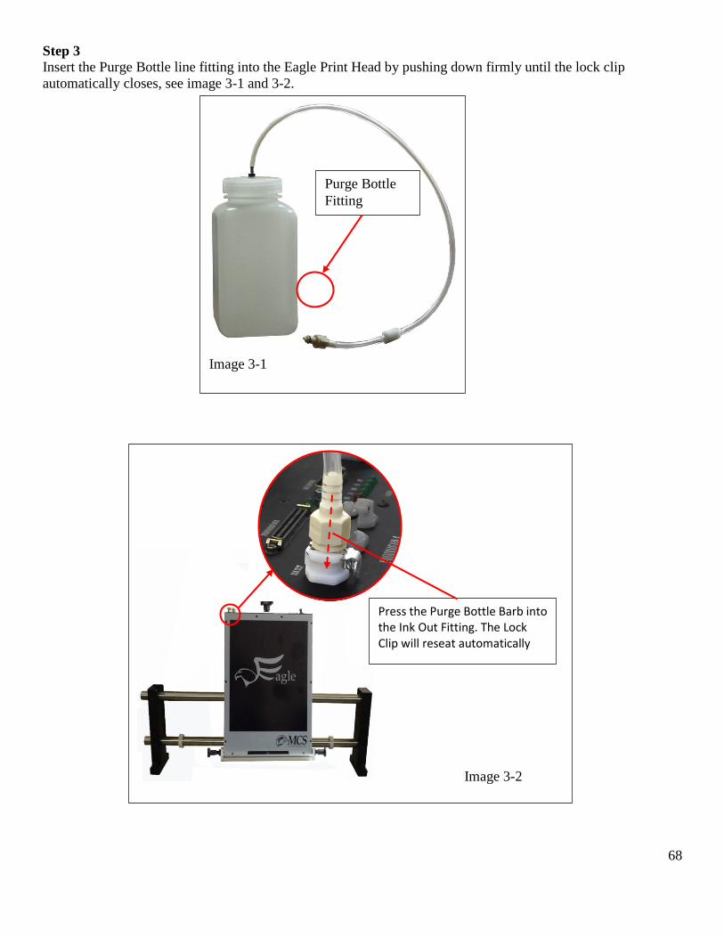
Step 3
Insert the Purge Bottle line fitting into the Eagle Print Head by pushing down firmly until the lock clip
automatically closes, see image 3-1 and 3-2.
Image 3-2
Press the Purge Bottle Barb into the Ink Out Fitting. The Lock Clip will reseat automatically
Image 3-1
Purge Bottle
Fitting
69
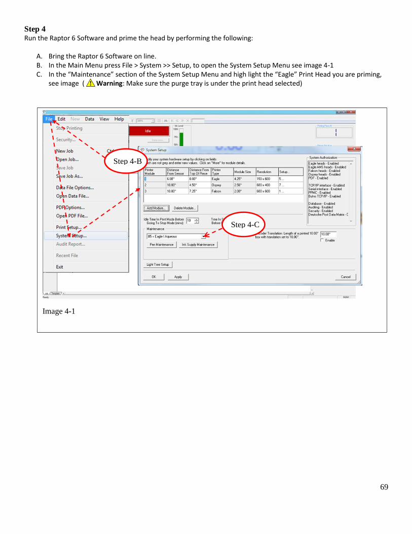
Step 4 Run the Raptor 6 Software and prime the head by performing the following:
A. Bring the Raptor 6 Software on line. B. In the Main Menu press File > System >> Setup, to open the System Setup Menu see image 4-1 C. In the “Maintenance” section of the System Setup Menu and high light the “Eagle” Print Head you are priming,
see image ( Warning: Make sure the purge tray is under the print head selected)
Image 4-1
Step 4-B
Step 4-C
!
70
!
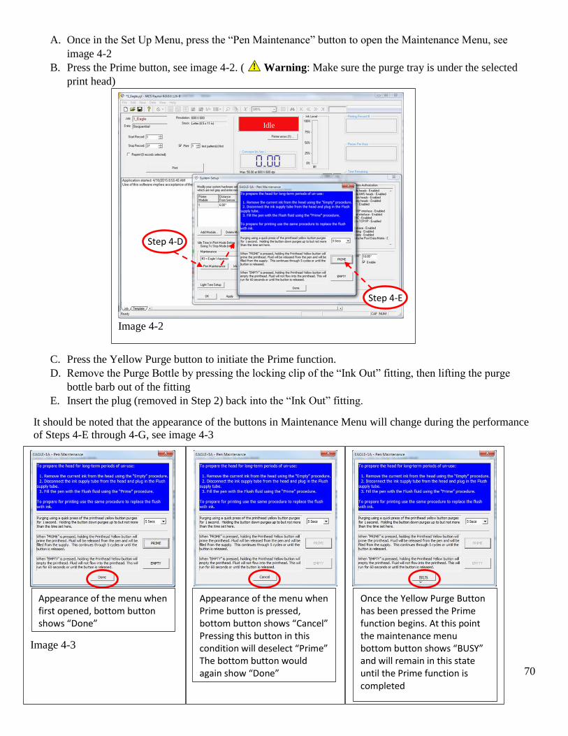
A. Once in the Set Up Menu, press the “Pen Maintenance” button to open the Maintenance Menu, see
image 4-2
B. Press the Prime button, see image 4-2. ( Warning: Make sure the purge tray is under the selected
print head)
C. Press the Yellow Purge button to initiate the Prime function.
D. Remove the Purge Bottle by pressing the locking clip of the “Ink Out” fitting, then lifting the purge
bottle barb out of the fitting
E. Insert the plug (removed in Step 2) back into the “Ink Out” fitting.
It should be noted that the appearance of the buttons in Maintenance Menu will change during the performance
of Steps 4-E through 4-G, see image 4-3
Image 4-3
Appearance of the menu when first opened, bottom button shows “Done”
Appearance of the menu when Prime button is pressed, bottom button shows “Cancel” Pressing this button in this condition will deselect “Prime” The bottom button would again show “Done”
BUS
Y
Once the Yellow Purge Button has been pressed the Prime function begins. At this point the maintenance menu bottom button shows “BUSY” and will remain in this state until the Prime function is completed
Image 4-2
Step 4-D
Step 4-E
Idle
71
!
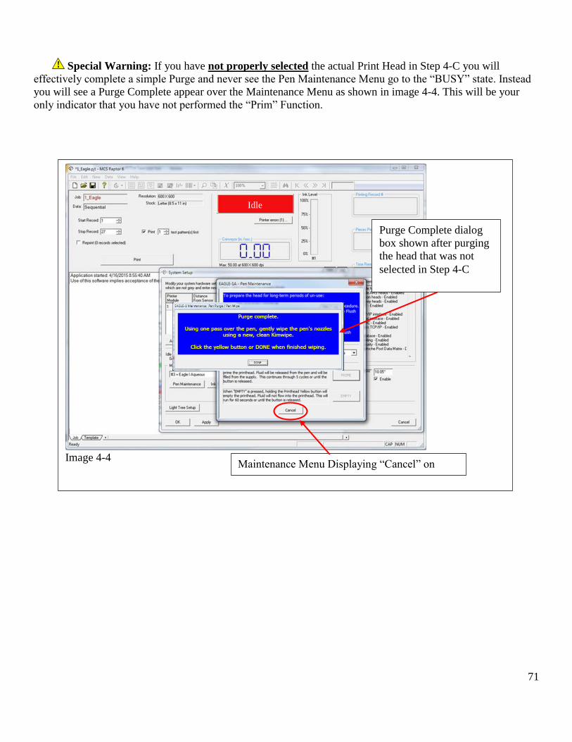
Special Warning: If you have not properly selected the actual Print Head in Step 4-C you will
effectively complete a simple Purge and never see the Pen Maintenance Menu go to the “BUSY” state. Instead
you will see a Purge Complete appear over the Maintenance Menu as shown in image 4-4. This will be your
only indicator that you have not performed the “Prim” Function.
Image 4-4
Idle
Maintenance Menu Displaying “Cancel” on
button
Purge Complete dialog
box shown after purging
the head that was not
selected in Step 4-C
72
9.2 Prepare for Storage In the event your machine will be disconnected from power for a 90 day time period or more or you plan to ship the machine to another location it should be prepared for storage. To prepare the Eagle Print Head for storage, perform the following:
Step 1
Raise the Print Head and remove the cover in the following manner:
A. Raise the Eagle Print head to its highest setting by pulling out the lock knob, manually lifting the Eagle
Print Head and pushing the lock knob to its original position.
B. If the print head is covered, remove the cover on the bottom in the following manner: b-1. Pull both retaining lock knobs out from the head at the same time b-2. Once the locks are out of the head pull the cover down and away from the head and set the cover aside see image 1-1.
C. Place a Purge Tray under the Eagle Print Head you intend to select as a precaution to guard against ink
dripping onto the belts during this procedure.
Image 1-1
Pull both locks then take down cover
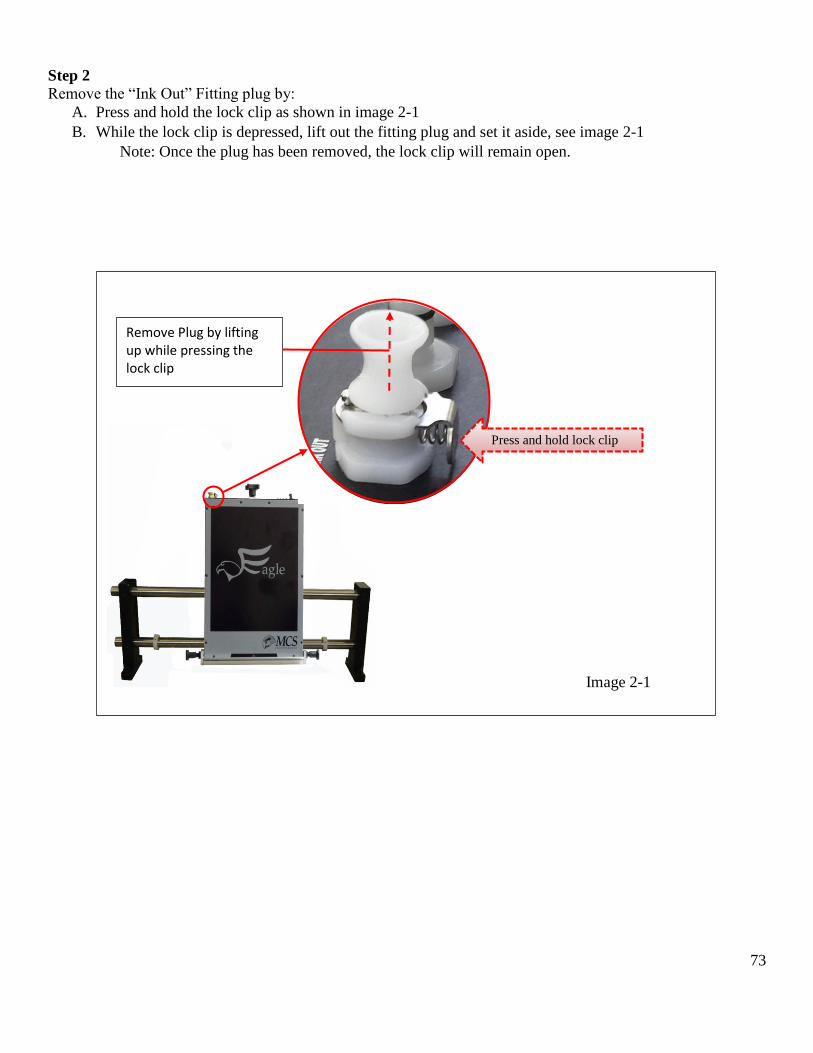
73
Step 2
Remove the “Ink Out” Fitting plug by:
A. Press and hold the lock clip as shown in image 2-1
B. While the lock clip is depressed, lift out the fitting plug and set it aside, see image 2-1
Note: Once the plug has been removed, the lock clip will remain open.
Image 2-1
Press and hold lock clip
Remove Plug by lifting up while pressing the lock clip
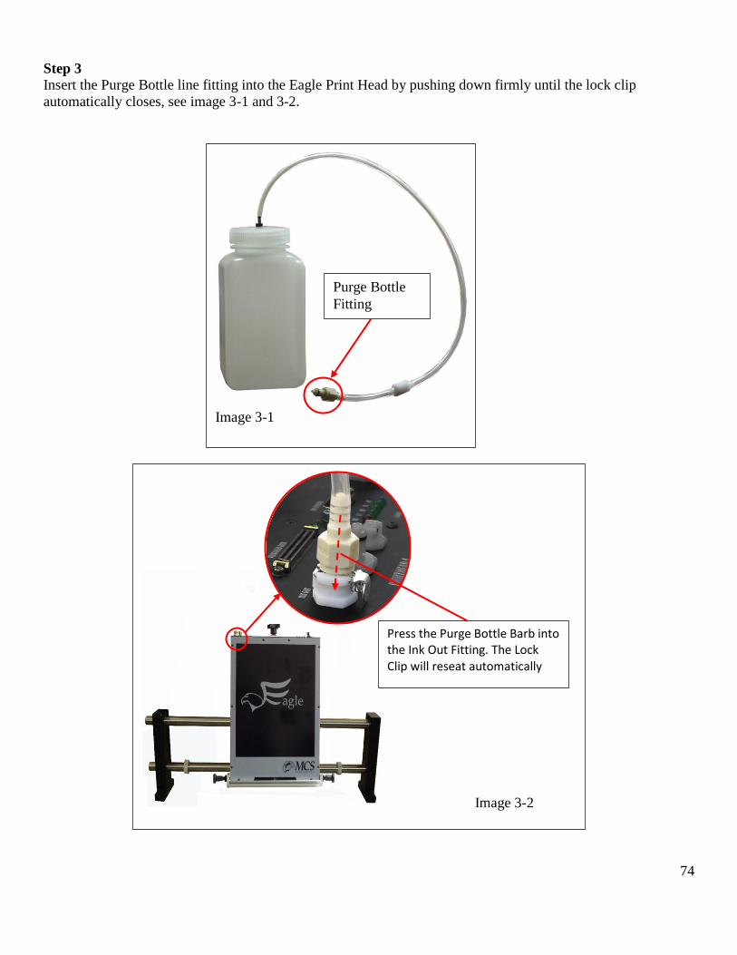
74
Step 3
Insert the Purge Bottle line fitting into the Eagle Print Head by pushing down firmly until the lock clip
automatically closes, see image 3-1 and 3-2.
Image 3-2
Press the Purge Bottle Barb into the Ink Out Fitting. The Lock Clip will reseat automatically
Image 3-1
Purge Bottle
Fitting
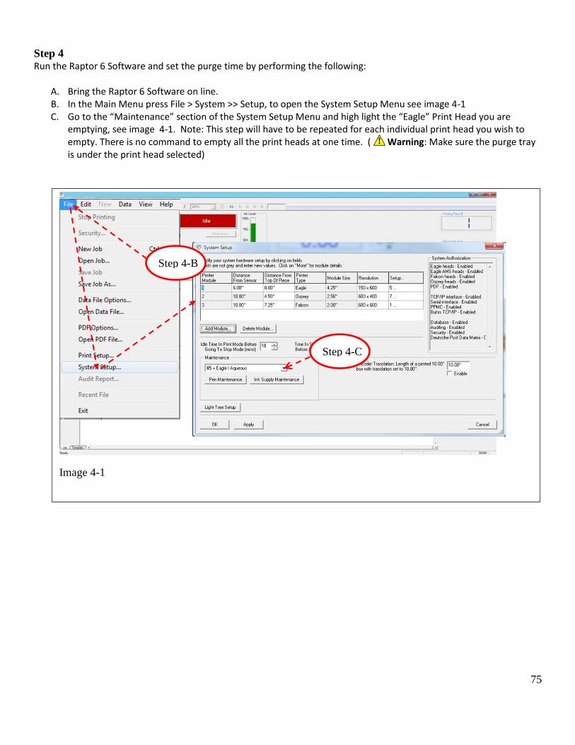
75
Step 4 Run the Raptor 6 Software and set the purge time by performing the following:
A. Bring the Raptor 6 Software on line. B. In the Main Menu press File > System >> Setup, to open the System Setup Menu see image 4-1 C. Go to the “Maintenance” section of the System Setup Menu and high light the “Eagle” Print Head you are
emptying, see image 4-1. Note: This step will have to be repeated for each individual print head you wish to empty. There is no command to empty all the print heads at one time. ( Warning: Make sure the purge tray is under the print head selected)
Image 4-1
Step 4-B
Step 4-C
!
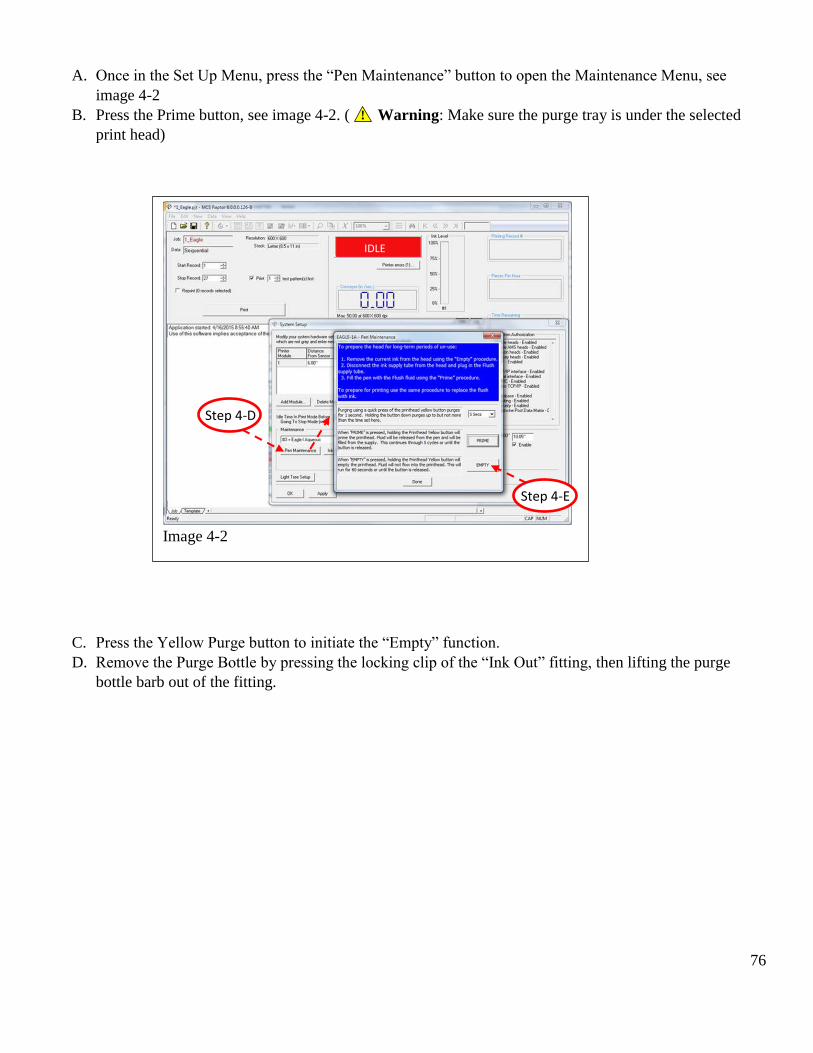
76
!
A. Once in the Set Up Menu, press the “Pen Maintenance” button to open the Maintenance Menu, see
image 4-2
B. Press the Prime button, see image 4-2. ( Warning: Make sure the purge tray is under the selected
print head)
C. Press the Yellow Purge button to initiate the “Empty” function.
D. Remove the Purge Bottle by pressing the locking clip of the “Ink Out” fitting, then lifting the purge
bottle barb out of the fitting.
Idle
Image 4-2
Step 4-D
Step 4-E
IDLE
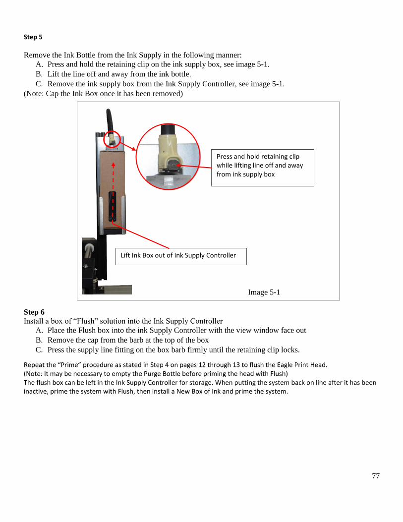
77
Step 5
Remove the Ink Bottle from the Ink Supply in the following manner:
A. Press and hold the retaining clip on the ink supply box, see image 5-1.
B. Lift the line off and away from the ink bottle.
C. Remove the ink supply box from the Ink Supply Controller, see image 5-1.
(Note: Cap the Ink Box once it has been removed)
Step 6
Install a box of “Flush” solution into the Ink Supply Controller
A. Place the Flush box into the ink Supply Controller with the view window face out
B. Remove the cap from the barb at the top of the box
C. Press the supply line fitting on the box barb firmly until the retaining clip locks.
Repeat the “Prime” procedure as stated in Step 4 on pages 12 through 13 to flush the Eagle Print Head. (Note: It may be necessary to empty the Purge Bottle before priming the head with Flush) The flush box can be left in the Ink Supply Controller for storage. When putting the system back on line after it has been inactive, prime the system with Flush, then install a New Box of Ink and prime the system.
Image 5-1
Press and hold retaining clip while lifting line off and away from ink supply box
Lift Ink Box out of Ink Supply Controller

78