Embed Size (px)
Citation preview
Chemical Industry & Chemical Engineering Quarterly
Available on line at Association of the Chemical Engineers of Serbia AChE www.ache.org.rs/CICEQ
Chem. Ind. Chem. Eng. Q. 23 (3) 311−320 (2017) CI&CEQ
311
R.A.F. OLIVEIRA1
G.H. JUSTI2 G.C. LOPES1
1Graduate Program in Chemical Engineering, Federal University of São Carlos, Rodovia Washington
Luís, , São Carlos - São Paulo – Brazil
2Institute of Engineering, Federal University of Mato Grosso, Av.
Fernando Corrêa da Costa Cuiabá – Mato Grosso – Brazil
SCIENTIFIC PAPER
UDC 532.5:66:51:633.63:628.3
GRID CONVERGENCE STUDY OF A CYCLONE SEPARATOR USING DIFFERENT MESH STRUCTURES
Article Highlights • A numerical study of a cyclone separator was carried out using CFD techniques • A grid independence analysis was carried out to optimize simulation effort and accuracy • Two mesh structures were used to find out the best numerical mesh for these
simulations • Wall-refined meshes better represent collection efficiency • Regular element meshes better represent pressure drop Abstract
In a cyclone design, pressure drop and collection efficiency are two important performance parameters to estimate its implementation viability. The optimum design provides higher efficiencies and lower pressure drops. In this paper, a grid independence study was performed to determine the most appropriate mesh to simulate the two-phase flow in a Stairmand cyclone. Computational fluid dynamic (CFD) tools were used to simulate the flow in an Eulerian-Lagrangian approach. Two different mesh structure, one with wall-refinement and the other with regular elements, and several mesh sizes were tested. The grid convergence index (GCI) method was applied to evaluate the result indepen-dence. The CFD model results were compared with empirical correlations from bibliography, showing good agreement. The wall-refined mesh with 287 thous-and elements obtained errors of 9.8% for collection efficiency and 14.2% for pressure drop, while the same mesh, with regular elements, obtained errors of 8.7% for collection efficiency and 0.01% for pressure drop.
Keywords: CFD, cyclone separator, bagasse soot, numerical mesh, grid convergence index.
As researchers came into a consensus about all harmful effects of fossil fuels on health and due to the high prices of gasoline, renewable fuels such as ethanol from sugarcane became a solution that is not only cheaper, but also less harmful to health and of lower impact to the environment.
As a secondary product, the bagasse of the milled sugarcane still has energetic value and it is generally combusted, in order to produce electric energy to sustain the whole industry and, sometimes, Correspondence: R.A.F. Oliveira, Department of Chemical Eng-ineering, Federal University of São Carlos, Rodovia Washington Luís, km 235 - SP-310, P.O. Box: 13565-905, São Carlos - São Paulo – Brazil. Paper received: 16 May, 2016 Paper revised: 8 July, 2016 Paper accepted: 17 September, 2016
https://doi.org/10.2298/CICEQ160516044O
sell the exceeding energy. However, its combustion produces sugarcane bagasse soot, a particulate matter also noxious to health and environment that cannot be simply dumped at the environment.
So, in order to control the emission of particulate matter at atmosphere, industries install specific equip-ment for gas effluent treatment at the outlet of the boiler, such as cyclone separators, electrostatic pre-cipitators or Venturi scrubbers. One of the main used device on air treatment is the cyclone separator, due to its low cost on building, maintenance and capacity of operating at high pressures and temperatures [1,2], and its wide range of gas flow treatment, reaching values between 50 and 50000 m3/h [3].
Even though these advantages, its usage is limited to its collection efficiency of particles with dia-meter lower than 2 µm, compared to other equipment
R.A.F. OLIVEIRA et al.: GRID CONVERGENCE STUDY OF A CYCLONE… Chem. Ind. Chem. Eng. Q. 23 (3) 311−320 (2017)
312
[4], so that cyclone separators are generally used as a pre-collection device, attached to other equipment with higher efficiency.
The usage of computational fluid dynamics (CFD) is a cheap and reliable way to predict the complex flow field and particle trajectories inside a cyclone separator [5,6] in order to optimize the viability of implementation of equipment in a process, saving time and money for the industry. In order to optimize a simulation, impro-ving its accuracy without increasing the simulation time and machine effort, a grid independence study should be performed before running cases.
When studying cyclone separator by CFD methods, researchers emphasize on optimization of the device, by analyzing the effects of the dimensions and operational conditions. Zhao, Su and Zhang [7] compared the effects of a spiral double inlet and a single inlet in the performance, obtaining a better gas flow pattern in a double spiral inlet, while Elsayed and Lacor [8] studied the performance of the device com-paring different widths and heights, concluding that the width is more relevant than the height for collection effi-ciency.
Studies of effects of the height of the cyclone are carried out for different cone and cylinder lengths. It is common to see in the literature studies of the cone effects, comparing the performance of different heights and bottom diameter [9-11], obtaining better collection efficiency as the bottom diameter is reduced. In this research field, Brar, Sharma and Elsayed [12] carried out numerical simulations not only for different cone lengths, but also for different cylinder heights, con-cluding that increasing the cylinder mainly saves more pressure drop, while the major benefit of increasing the cone is the improvement of the collection efficiency.
It is recurring to see studies that optimize the performance by restructuring the depth and diameter of the vortex finder. Recent researches showed that a smaller pressure drop per flow rate unit can be achieved when a cone-shaped vortex finder is used, although the collection efficiency was insignificant for smaller vortex finder [13,14]. Other vortex finder inno-vation is seen in the work of Safikhani and Mehrabia [15], whose proposal consists of an outer cylinder and vortex limiter, instead of a conical part, decreasing the pressure drop.
The mesh generation is one of the most important requirements in CFD simulation. Understanding the influence of the mesh size and structure on the flow fields is essential to get reliable results. The analysis of different mesh parameters allows the obtaining of a suitable mesh for a specific problem with acceptable computational effort and numerical accuracy [16].
Barthe and Zhang [17], for example, showed the importance of adapting the fluid mesh when high gra-dients are present or boundary layer effects are imp-ortant and proposed a mesh adaptivity procedure using triangular and tetrahedral elements in the mesh.
It is known that great velocity and pressure gradients are observed in cyclone separators, so that wall effects are essential to be analyzed in CFD sim-ulations of these devices. It is common to see meshes with a high quantity of elements, in order to obtain accurate results near walls [8,15,17]. However, few studies are concerned with the influence of the mesh structure on the flow field in cyclones. In this context, the present study aims to propose proper mesh struc-ture and size for a laboratory Stairmand cyclone separ-ator with low quantity of elements without losing accur-acy. For this purpose, a grid independence study was performed, using the grid convergence index (GCI) method, which consists in quantifying the numerical uncertainty by basing on the Richardson extrapolation method for discretization error estimation, so that a consistent and reliable report of the grid refinement and its accuracy is obtained [18].
METHODOLOGY
Design and meshes generation
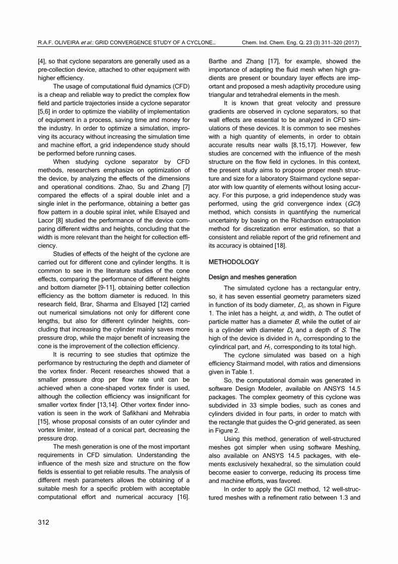
The simulated cyclone has a rectangular entry, so, it has seven essential geometry parameters sized in function of its body diameter, Dc, as shown in Figure 1. The inlet has a height, a, and width, b. The outlet of particle matter has a diameter B, while the outlet of air is a cylinder with diameter De and a depth of S. The high of the device is divided in hc, corresponding to the cylindrical part, and HT, corresponding to its total high.
The cyclone simulated was based on a high efficiency Stairmand model, with ratios and dimensions given in Table 1.
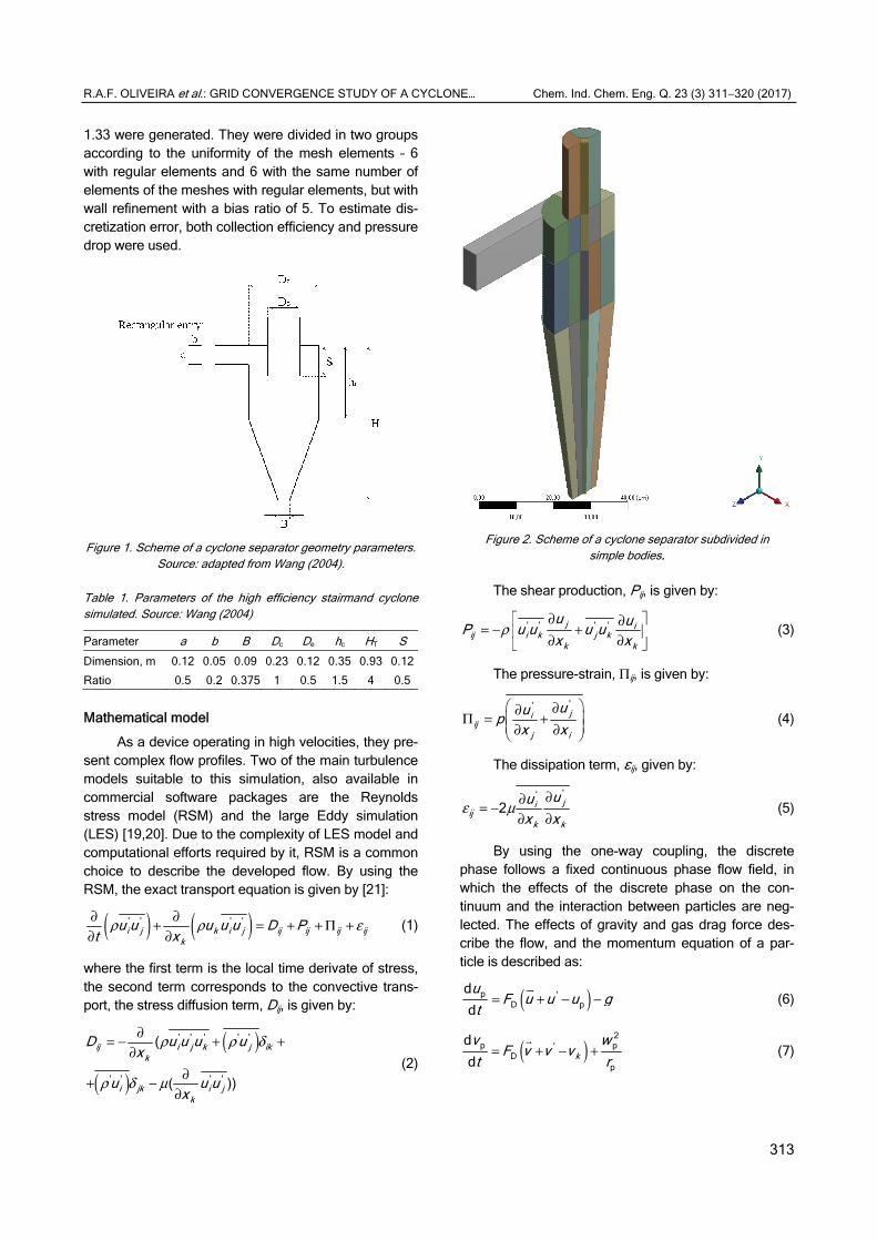
So, the computational domain was generated in software Design Modeler, available on ANSYS 14.5 packages. The complex geometry of this cyclone was subdivided in 33 simple bodies, such as cones and cylinders divided in four parts, in order to match with the rectangle that guides the O-grid generated, as seen in Figure 2.
Using this method, generation of well-structured meshes got simpler when using software Meshing, also available on ANSYS 14.5 packages, with ele-ments exclusively hexahedral, so the simulation could become easier to converge, reducing its process time and machine efforts, was favored.
In order to apply the GCI method, 12 well-struc-tured meshes with a refinement ratio between 1.3 and
R.A.F. OLIVEIRA et al.: GRID CONVERGENCE STUDY OF A CYCLONE… Chem. Ind. Chem. Eng. Q. 23 (3) 311−320 (2017)
313
1.33 were generated. They were divided in two groups according to the uniformity of the mesh elements – 6 with regular elements and 6 with the same number of elements of the meshes with regular elements, but with wall refinement with a bias ratio of 5. To estimate dis-cretization error, both collection efficiency and pressure drop were used.
Figure 1. Scheme of a cyclone separator geometry parameters.
Source: adapted from Wang (2004).
Table 1. Parameters of the high efficiency stairmand cyclone simulated. Source: Wang (2004)
Parameter a b B Dc De hc HT S
Dimension, m 0.12 0.05 0.09 0.23 0.12 0.35 0.93 0.12
Ratio 0.5 0.2 0.375 1 0.5 1.5 4 0.5
Mathematical model
As a device operating in high velocities, they pre-sent complex flow profiles. Two of the main turbulence models suitable to this simulation, also available in commercial software packages are the Reynolds stress model (RSM) and the large Eddy simulation (LES) [19,20]. Due to the complexity of LES model and computational efforts required by it, RSM is a common choice to describe the developed flow. By using the RSM, the exact transport equation is given by [21]:
( ) ( )ρ ρ ε∂ ∂+ = + + Π +∂ ∂
' ' ' 'i j k i j ij ij ij ij
k
u u u u u D Pt x
(1)
where the first term is the local time derivate of stress, the second term corresponds to the convective trans-port, the stress diffusion term, Dij, is given by:
( )
( )
' ' ' ' '
' ' ' '
(
( ))
ij i j k j ikk
i jk i jk
D u u u ux
u u ux
ρ ρ δ
ρ δ μ
∂= − + +∂
∂+ −∂
(2)
Figure 2. Scheme of a cyclone separator subdivided in
simple bodies.
The shear production, Pij, is given by:
ρ∂ ∂= − + ∂ ∂
' ' ' 'j iij i k j k
k k
u uP u u u ux x
(3)
The pressure-strain, Πij, is given by:
∂∂ Π = + ∂ ∂
''ji
ijj i
uupx x
(4)
The dissipation term, εij, given by:
ε μ∂∂= −
∂ ∂
''
2 jiij
k k
uux x
(5)
By using the one-way coupling, the discrete phase follows a fixed continuous phase flow field, in which the effects of the discrete phase on the con-tinuum and the interaction between particles are neg-lected. The effects of gravity and gas drag force des-cribe the flow, and the momentum equation of a par-ticle is described as:
( )= + − −
p 'D p
ddu
F u u u gt
(6)
( )= + − + 2
p p'D
p
dd kv w
F v v vt r
(7)
R.A.F. OLIVEIRA et al.: GRID CONVERGENCE STUDY OF A CYCLONE… Chem. Ind. Chem. Eng. Q. 23 (3) 311−320 (2017)
314
( )= + − −
p p p'D p
p
ddw v w
F w w wt r
(8)
where the momentum transport coefficient between fluid and particles, FD, is given by:
μρ
= D pD 2
p p
18 Re24
CF
d (9)
the drag coefficient for particles, CD, is given by:
( )
≤ += < ≤ >
pp
0.687p
D pp
p
24Re 1
Re
24 1 0.15Re1 Re 1000
Re
0.44 Re 1000
C
(10a)
(10b)
(10c)
and Rep is the particle Reynolds number, given by:
ρ ϑ ϑ
μ
−=
g p g p
pRed
(11)
where ϑ assumes velocity components u, v and w.
Case set up
A gas-solid mixture at 20 m/s and 45.5 °C of air, with density of 1.103 kg/m3 and viscosity of 1.8582×10⁻⁵ Pa·s, and sugarcane bagasse soot with average particle diameter of 9 µm and density of 2351.1 kg/m³. As the focus of this paper is to analyze the structure of the meshes, the diameter of the particle was set as constant, in order to simplify the simulations, which were carried out using Fluent Solver 14.5 in an Euler-ian-Lagrangian approach, in which the gas was treated as continuum phase, particulate phase was treated as single particles and particle trajectories, representing a stream of particles, are calculated as a result of a bal-ance of forces acting on them, by using a one-way coupling.
Each simulation was set up in a transient state with a time step of 0.0001 second for 10000 time steps, in order to simulate a cyclone operating for 1 s. This was enough to ensure that the inlet static pressure converged to a steady state.
Spatial discretization was carried out in a second order upwind Scheme, adopting the spherical drag law model for drag coefficient and the SIMPLE scheme for pressure-velocity coupling.
The solution was set to converge when the residuals of all the flow variables, such as continuity, turbulent kinetic energy, turbulent dissipation and stress tensors, fell below 1×10⁻⁵ and the monitored total
pressures at the surface of inlet and the surface of the outlet of air became steady. All the numerical simul-ations were carried out using the default relaxation factor values in the Fluent solver.
As soon as static pressure of air at the inlet con-verged to a steady value, particles were injected in the domain at 20 m/s using a one-way coupling scheme, in which the effects of interaction between particles and the gas are neglected, and its flow was tracked, using the discrete phase model (DPM). In this model, par-ticles were set up to reflect on wall, escape on air outlet and get trapped when reaches the bottom of the cycl-one.
In order to use this coupling scheme, it is neces-sary to assume that the dispersed phase occupies a low volume fraction, generally lower than 10% [18]. To ensure that this condition was suited, the injection of particles was set up to be proportional to the number of elements in the inlet of the numerical mesh.
Grid independence analysis
In this study, the GCI method was used to opti-mize the simulation, choosing a numerical mesh which results in higher precision and lower required machine effort.
The procedure for estimation of discretization error suggested [20] is, first of all, defining a represent-ative mesh size h, given by:
=
= Δ
13
1
1 N
i
h VN
(12)
where ΔVi is the volume of the ith cell and N is the total number of cells used for the computations.
It is desirable a grid refinement factor, given by Eq. (13), greater than 1.3 and constant, based on experimental studies [20]:
= coarse
fine
hrh
(13)
After selecting the 3 finest meshes and running simulations to determine the values of relevant vari-ables, φi, the apparent order, p, is calculated using fixed-point iteration in the equations:
εε
= +32
21 21
1ln ( )
lnp q p
r (14)
−= − 21
32
( ) lnp
pr sq pr s
(15)
32
211 signs ε
ε = ⋅
(16)
R.A.F. OLIVEIRA et al.: GRID CONVERGENCE STUDY OF A CYCLONE… Chem. Ind. Chem. Eng. Q. 23 (3) 311−320 (2017)
315
where h1 < h2 < h3, r21 = h2/h1, r32 = h3/h2, ε32 = φ3-φ2, ε21 = φ2-φ1 and φk is the solution on the kth mesh.
So, extrapolated values can be calculated by the Eq. (16), and similarly it can be done for φ32
ext . By calculating the extrapolated values, approximate relative error and extrapolated relative error can be estimated by Eqs. (17) and (18), respectively:
φ φφ −=−
21 21 1 2ext
21 1
p
pr
r (17)
φ φφ−=21 1 2
a1
e (18)
φ φφ
−=21
21 ext 1ext 21
ext
e (19)
At last, the grid convergence index can be cal-culated by the Eq. (19) as follows:
=−
2121 afine
21
1.251p
eGCIr
(20)
RESULTS AND DISCUSSION
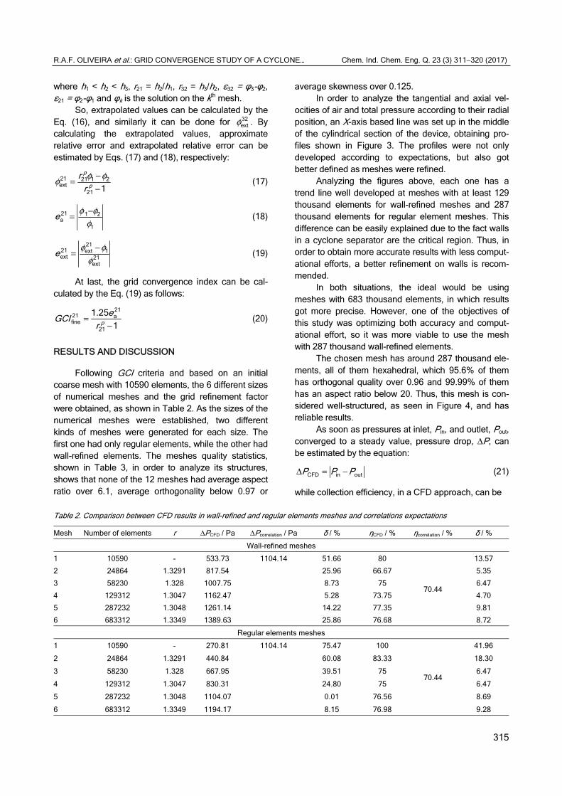
Following GCI criteria and based on an initial coarse mesh with 10590 elements, the 6 different sizes of numerical meshes and the grid refinement factor were obtained, as shown in Table 2. As the sizes of the numerical meshes were established, two different kinds of meshes were generated for each size. The first one had only regular elements, while the other had wall-refined elements. The meshes quality statistics, shown in Table 3, in order to analyze its structures, shows that none of the 12 meshes had average aspect ratio over 6.1, average orthogonality below 0.97 or
average skewness over 0.125. In order to analyze the tangential and axial vel-
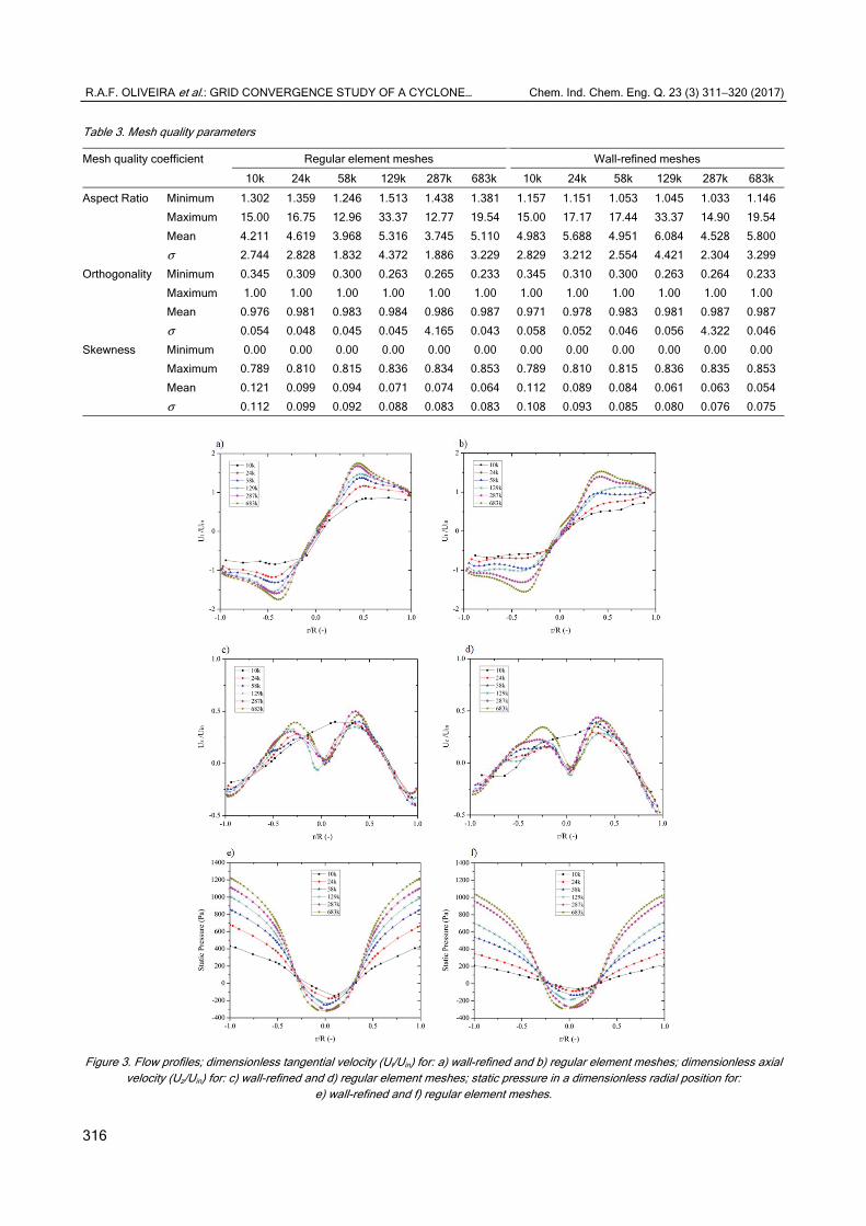
ocities of air and total pressure according to their radial position, an X-axis based line was set up in the middle of the cylindrical section of the device, obtaining pro-files shown in Figure 3. The profiles were not only developed according to expectations, but also got better defined as meshes were refined.
Analyzing the figures above, each one has a trend line well developed at meshes with at least 129 thousand elements for wall-refined meshes and 287 thousand elements for regular element meshes. This difference can be easily explained due to the fact walls in a cyclone separator are the critical region. Thus, in order to obtain more accurate results with less comput-ational efforts, a better refinement on walls is recom-mended.
In both situations, the ideal would be using meshes with 683 thousand elements, in which results got more precise. However, one of the objectives of this study was optimizing both accuracy and comput-ational effort, so it was more viable to use the mesh with 287 thousand wall-refined elements.
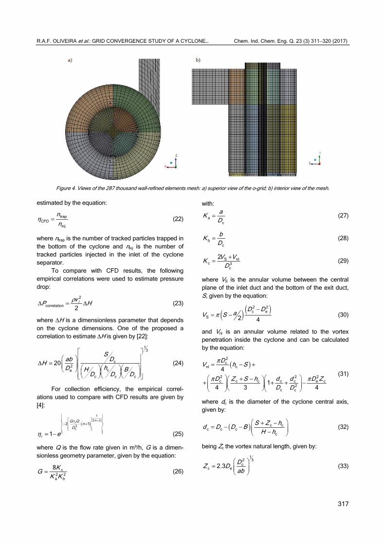
The chosen mesh has around 287 thousand ele-ments, all of them hexahedral, which 95.6% of them has orthogonal quality over 0.96 and 99.99% of them has an aspect ratio below 20. Thus, this mesh is con-sidered well-structured, as seen in Figure 4, and has reliable results.
As soon as pressures at inlet, Pin, and outlet, Pout, converged to a steady value, pressure drop, ΔP, can be estimated by the equation:
Δ = −CFD in outP P P (21)
while collection efficiency, in a CFD approach, can be
Table 2. Comparison between CFD results in wall-refined and regular elements meshes and correlations expectations
Mesh Number of elements r ΔPCFD / Pa ΔPcorrelation / Pa δ / % ηCFD / % ηcorrelation / % δ / %
Wall-refined meshes
1 10590 - 533.73 1104.14 51.66 80
70.44
13.57
2 24864 1.3291 817.54 25.96 66.67 5.35
3 58230 1.328 1007.75 8.73 75 6.47
4 129312 1.3047 1162.47 5.28 73.75 4.70
5 287232 1.3048 1261.14 14.22 77.35 9.81
6 683312 1.3349 1389.63 25.86 76.68 8.72
Regular elements meshes
1 10590 - 270.81 1104.14 75.47 100
70.44
41.96
2 24864 1.3291 440.84 60.08 83.33 18.30
3 58230 1.328 667.95 39.51 75 6.47
4 129312 1.3047 830.31 24.80 75 6.47
5 287232 1.3048 1104.07 0.01 76.56 8.69
6 683312 1.3349 1194.17 8.15 76.98 9.28
R.A.F. OLIVEIRA et al.: GRID CONVERGENCE STUDY OF A CYCLONE… Chem. Ind. Chem. Eng. Q. 23 (3) 311−320 (2017)
316
Table 3. Mesh quality parameters
Mesh quality coefficient Regular element meshes Wall-refined meshes
10k 24k 58k 129k 287k 683k 10k 24k 58k 129k 287k 683k
Aspect Ratio Minimum 1.302 1.359 1.246 1.513 1.438 1.381 1.157 1.151 1.053 1.045 1.033 1.146
Maximum 15.00 16.75 12.96 33.37 12.77 19.54 15.00 17.17 17.44 33.37 14.90 19.54
Mean 4.211 4.619 3.968 5.316 3.745 5.110 4.983 5.688 4.951 6.084 4.528 5.800
σ 2.744 2.828 1.832 4.372 1.886 3.229 2.829 3.212 2.554 4.421 2.304 3.299
Orthogonality Minimum 0.345 0.309 0.300 0.263 0.265 0.233 0.345 0.310 0.300 0.263 0.264 0.233
Maximum 1.00 1.00 1.00 1.00 1.00 1.00 1.00 1.00 1.00 1.00 1.00 1.00
Mean 0.976 0.981 0.983 0.984 0.986 0.987 0.971 0.978 0.983 0.981 0.987 0.987
σ 0.054 0.048 0.045 0.045 4.165 0.043 0.058 0.052 0.046 0.056 4.322 0.046
Skewness Minimum 0.00 0.00 0.00 0.00 0.00 0.00 0.00 0.00 0.00 0.00 0.00 0.00
Maximum 0.789 0.810 0.815 0.836 0.834 0.853 0.789 0.810 0.815 0.836 0.835 0.853
Mean 0.121 0.099 0.094 0.071 0.074 0.064 0.112 0.089 0.084 0.061 0.063 0.054
σ 0.112 0.099 0.092 0.088 0.083 0.083 0.108 0.093 0.085 0.080 0.076 0.075
Figure 3. Flow profiles; dimensionless tangential velocity (Ut/Uin) for: a) wall-refined and b) regular element meshes; dimensionless axial
velocity (Uz/Uin) for: c) wall-refined and d) regular element meshes; static pressure in a dimensionless radial position for: e) wall-refined and f) regular element meshes.
R.A.F. OLIVEIRA et al.: GRID CONVERGENCE STUDY OF A CYCLONE… Chem. Ind. Chem. Eng. Q. 23 (3) 311−320 (2017)
317
Figure 4. Views of the 287 thousand wall-refined elements mesh: a) superior view of the o-grid; b) interior view of the mesh.
estimated by the equation:
η = trapCFD
inj
nn
(22)
where ntrap is the number of tracked particles trapped in the bottom of the cyclone and ninj is the number of tracked particles injected in the inlet of the cyclone separator.
To compare with CFD results, the following empirical correlations were used to estimate pressure drop:
ρΔ = Δ2
correlation 2ivP H (23)
where ΔH is a dimensionless parameter that depends on the cyclone dimensions. One of the proposed a correlation to estimate ΔH is given by [22]:
13
c2
ce
c c c
20S
DabHhD H B
D D D
Δ =
(24)
For collection efficiency, the empirical correl-ations used to compare with CFD results are given by [4]:
( )τ
η
+ − ⋅ +
= −
12 2
3c
2 1
1
niG Qn
D
i e (25)
where Q is the flow rate given in m³/h, G is a dimen-sionless geometry parameter, given by the equation:
= c2 2a b
8KGK K
(26)
with:
=ac
aKD
(27)
=bc
bKD
(28)
+= S nlc 3
c
2V VKD
(29)
where VS is the annular volume between the central plane of the inlet duct and the bottom of the exit duct, S, given by the equation:
( ) ( )π
−= −
2 2c e
S 2 4
D DaV S (30)
and Vnl is an annular volume related to the vortex penetration inside the cyclone and can be calculated by the equation:
( )π
π π
= − +
+ − + + + −
2c
nl c
2 2 2c c c c c e c
2c c
4
14 3 4
DV h S
D Z S h d d D ZD D
(31)
where dc is the diameter of the cyclone central axis, given by:
( ) + −= − − − c c
c c cc
S Z hd D D BH h
(32)
being Zc the vortex natural length, given by:
=
132
cc e2.3
DZ Dab
(33)
R.A.F. OLIVEIRA et al.: GRID CONVERGENCE STUDY OF A CYCLONE… Chem. Ind. Chem. Eng. Q. 23 (3) 311−320 (2017)
318
and n is the vortex exponent, given by:
( ) = − −
0.30.14c1 1 0.67
283Tn D (34)
with Dc given in meters and the gas temperature T in Kelvin. Finally, the relaxation time, τi, given by:
ρτ
μ=
2p
18i
iD
(35)
After calculating pressure drop and efficiency by CFD and empirical correlations, relative errors can be estimated by the equation:
φ φδφ
−= CFD correlation
correlation
100 (36)
where φ is the analyzed variable. Another consequence of the results obtained on
CFD model is the estimation of the apparent order and GCI for both collection efficiency and pressure drop for each mesh refinement, as shown in Table 4, where pi is the apparent order for the ith parameter φi, being 1 the collection efficiency and 2 the pressure drop.
Table 4. Apparent order and GCI for collection efficiency and pressure drop for different kinds of meshes
Grid Step
Wall-refined meshes Regular elements meshes
p1 φ1
% p2 φ2
% p1 φ1
% p2 φ2
%
GCI21 5.753 6.04 0.6044 229.66 5.0741 7.73 4.3378 19.80
GCI32 3.38 128.14 4.31 17.54
GCI43 0.59 95.40 0.00 11.27
GCI54 1.60 56.06 0.89 14.28
GCI65 0.29 60.58 0.20 3.77
As seen in flow profiles on Figure 3, meshes with 683 thousand elements, for both regular elements and wall-refined meshes, better represented the trend of the expected flow, which could be confirmed by the GCI method.
Although the wall-refined mesh of 683 thousand elements developed a discretization error of 0.34% for pressure drop, a very low and good value, its discret-ization error for collection efficiency was 37.69%. So that, the better option was to simulate this device using the 287 thousand elements with wall refinement, which GCI for collection efficiency and pressure drop were, respectively, 3.08%, still a low and good value, and 17.40%, still a high value, but the lower obtained for the variable.
Now, comparing results between the two types of meshes with 287 thousand elements and expectations
from empirical correlations, results were coherent to predictions of CFD. Collection efficiency is affected by wall effects, such as drag and friction, so it was exp-ected a more reliable result of collection efficiency at the wall-refined mesh, as shown. As a variable equally distributed in the domain, a better accuracy for pres-sure is expected in meshes with regularly sized ele-ments, as observed on results of pressure drop.
CONCLUSION
After analyzing the obtained results of the 12 simulated meshes it is conclusive that the proposed model correctly represents the expected flow profiles. Due to the critical region of the cyclone separator being located at walls and at vortex region, wall-refined meshes developed the expected trend needing fewer elements than regular element meshes. This caused less simulation time and machine effort, which was one of the objectives of this paper.
Even though the chosen mesh had a higher discretization error for collection efficiency, it was not a significant issue. Gains on accuracy obtained in a more refined mesh did not compensate the necessary time to simulate the device.
Nomenclature
a Height of the cyclone inlet b Width of the cyclone inlet B Diameter of the particle matter outlet dc Diameter of the cyclone central axis Dc Diameter of the cyclone body De Diameter of air outlet Di Particle diameter ea Approximated relative error eext Extrapolated relative error DPM Discrete phase model G Geometric parameter in Eq. (26) GCI Grid convergence index h Representative mesh size hc Height of the cylindrical part of the cyclone HT Cyclone total height Ka Dimensionless parameter in Eq.(27) Kb Dimensionless parameter in Eq.(28) Kc Dimensionless parameter in Eq. (29) LES Large Eddy simulation N Vortex exponent ninj Number of injected particles in the inlet ntrap Number of trapped particles in particle outlet N Total number of elements in the mesh pi Apparent order of the ith analyzed parameter Pin Pressure in the inlet of the cyclone Pout Pressure in the air outlet of the cyclone Q Gas volumetric flow rate
R.A.F. OLIVEIRA et al.: GRID CONVERGENCE STUDY OF A CYCLONE… Chem. Ind. Chem. Eng. Q. 23 (3) 311−320 (2017)
319
r Grid refinement ratio RSM Reynolds stress model s Signal function S Internal height of the air outlet SIMPLE Semi-implicit method for pressure linked
equations T Temperature in K u Fluctuation velocity vi Gas velocity at the cyclone entry Vnl Annular volume between S and Zc Zc Vortex natural length
Greek δ Relative error ε Aggregated error ΔH Dimensionless parameter ΔPcorrelation Pressure drop by empirical correlation ΔPCFD Pressure drop by CFD correlation ΔV Volume of the ith element of the mesh ηcorrelation Collection efficiency by empirical
correlation ηCFD Collection efficiency by CFD correlation µ Gas viscosity ρ Gas density ρp Particle density σ Standard deviation τi Relaxation time φ Discrete solution φext Extrapolated discrete solution
Subscript i Cartesian coordinate j Cartesian coordinate k Cartesian coordinate in Inlet t Tangential z Z axis 21 refers to GCI between meshes 2 and 1 32 refers to GCI between meshes 3 and 2 43 refers to GCI between meshes 4 and 3 54 refers to GCI between meshes 5 and 4 65 refers to GCI between meshes 6 and 5
REFERENCES
[1] K. Elsayed, C. Lacor, Comput. Fluids 68 (2012) 134-147
[2] A. Kępa, Sep. Purif. Technol. 75 (2010) 127-131
[3] L.K. Wang, N.C. Pereira, Y. Hung (Eds.), Air Pollution Control Engineering, Humana Press Inc., New Jersey, 2004, pp. 97-105
[4] W.L. Heumann (Eds.), Industrial Air Pollution Control Systems, McGraw-Hill, New York, 1997, pp. 514-519
[5] W.D. Griffths, F. Boysan, J. Aerosol Sci. 27 (1996) 281- –304
[6] A.C. Hoffmann, L.E. Stein (Eds.), Gas Cyclones and Swirl Tubes: Principles, Design and Operation, Springer, New York, 2002, pp. 123-135
[7] B. Zhao, Y. Su, J. Zhang, Chem.Eng. Res. Des. 84 (2006) 1158-1165
[8] K. Elsayed, C. Lacor, Appl. Math. Model 35 (2011) 1952- –1968
[9] T.G. Chuah, J. Gimbun, T.S.Y. Choong, Powder Technol. 162 (2006) 126-132
[10] R. Xiang, S.H. Park, K.W. Lee, J Aerosol Sci. 32 (2011) 549-561
[11] R.B. Xiang, K.W. Lee, Sci. Technol. 19 (2001) 327-338
[12] L.S. Brar, R.P. Sharma, K. Elsayed, Powder Technol, 286 (2015) 668-677
[13] K.S. Lim, H.S. Kim, K.W. Lee, J. Aerosol Sci. 35 (2004) 743-754
[14] A. Raoufi, M. Shams, M. Farzaneh, R. Ebrahimi, Chem. Eng. Process. 47 (2008) 128-137
[15] H. Safikhani, P.Mehrabian, Adv. Powder Technol. 27 (2016) 379-387
[16] N.M.C. Marting, N.J.G. Carriço, H.M. Ramos, D.I.C. Covas, Comput. Fluids 105 (2014) 218-230
[17] K.Bathe, H. Zhang, Comput. Struct. 87 (2009) 604-617
[18] K. Elsayed, C. Lacor, Chem. Eng. Sci. 65 (2010) 6048- –6058
[19] A.Y.T. Leung, S.G. Bogodage, Powder Technol. 286 (2015) 488-506
[20] P.J. Roache, J. Fluids Eng. 116 (1994) 405-413
[21] B.E. Launder, Int. J. Heat Fluid Flow 10 (1989) 282-300
[22] G. Ramachandran, D. Leith, J. Dirgo, H. Feldman, Aerosol Sci. Technol. 15 (1991) 135-148.
R.A.F. OLIVEIRA et al.: GRID CONVERGENCE STUDY OF A CYCLONE… Chem. Ind. Chem. Eng. Q. 23 (3) 311−320 (2017)
320
R.A.F. OLIVEIRA1
G.H. JUSTI2 G.C. LOPES1
1Graduate Program in Chemical Engineering, Federal University of São Carlos, Rodovia Washington Luís, São
Carlos - São Paulo – Brazil 2Institute of Engineering, Federal
University of Mato Grosso, Av. Fernando Corrêa da Costa Cuiabá –
Mato Grosso – Brazil
NAUČNI RAD
PROUČAVANJE SEPARATORA CIKLONA KORIŠĆENJEM KONVERGENCIJE KOORDINATNE MREŽE RAZLIČITIH STRUKTURA
U projektovanju ciklona, dva značajna parametra za ocenu njegove praktične primenljivosti su smanjenje pritiska i efikasnost separacije. Optimalni dizajn pruža veću efikasnost i manji pad pritiska. U ovom radu, primenjene su nezavisne mreže kako bi se odredila naj-prikladnija mreža za simulaciju dvofaznog toka u Stairmand ciklonu. Alati proračunske dinamike fluide (CFD) sa Eulerian-Lagrangian pristupom korišćeni su za simulaciju pro-toka. Istražene su dve različite strukture mreže, sa nekoliko veličina okaca: jedna sa uti-cajem zida i druga sa regularnim elementima. Metoda indeksa konvergencije mreže (GCI) je primenjena za procenu nezavisnosti rezultata. Rezultati CFD modela upoređeni su sa empirijskim korelacijama iz literature i utvrđeno je dobrs slaganje. Prva mreža sa 287 hiljada elemenata dala je grešku od 9,8% za efikasnost separacije i 14,2% za pad pritiska, dok je ista mreža, sa regularnim elementima, dala grešku od 8,7% za efikasnost sepa-racije i 0,01% za pad pritiska.
Ključne reči: CFD, ciklon, čađ otpadaka prerade šečerne repe, numerička mreža, indeks konvergencije mreže.