Embed Size (px)
Citation preview
51
Radiografie e tomografie neutroniche
Neutron Radiography and Tomography
Lorenzo Visca, Thomas Bücherl, Giorgio Cotto, Marco Demmelbauer, Elisabetta Durisi, Walter Ferrarese, Francesco Grazzi, Alessandro Lo Giudice, Giorgia Mila, Alessandro Re, Roberto Sacchi, Antonella Scherillo
IntroduzioneLa radiografia e la tomografia a raggi X sono tecniche di indagine non distruttiva che tro-vano numerose applicazioni in vari ambiti tra i quali, come ampiamente illustrato nei capitoli precedenti, l’analisi della composi-zione, della struttura interna e dello stato di conservazione dei manufatti artistici. La disponibilità sul mercato di numerosi tipi di sorgenti e rivelatori per raggi X, con caratte-ristiche diversificate a seconda dell’impiego previsto, ha reso possibile la realizzazione degli apparati radio-tomografico e per l’a-nalisi con la tecnica del K-edge descritti nei capitoli precedenti.In anni recenti si è sviluppato un interes-se crescente per le radiografie e tomogra-fie effettuate utilizzando fasci di neutroni, specialmente nel campo delle applicazioni industriali. I neutroni interagiscono con la materia in modo profondamente diverso rispetto ai raggi X e, mentre possono facil-
mente attraversare spessi strati di metallo, subiscono un’elevata attenuazione quando incontrano elementi leggeri quali i composti organici (legno, pelle, ossa) e più in generale elementi contenenti idrogeno, boro o litio. I neutroni forniscono quindi informazioni complementari a quelle ottenibili con l’uti-lizzo dei raggi X e sono particolarmente in-dicati per l’analisi di spessi oggetti metallici o di elementi leggeri racchiusi in involucri me-tallici, che risulterebbero opachi ai raggi X. Di contro, l’utilizzo di neutroni presenta di-verse limitazioni che giustificano la sua scar-sa diffusione, se paragonato all’uso dei raggi X. Innanzitutto, fasci di neutroni sufficien-temente intensi e collimati per applicazio-ni radiografiche sono disponibili allo stato attuale in un numero esiguo di laboratori: presso reattori nucleari destinati alla ricerca o presso sorgenti di spallazione, ove si utiliz-zano potenti acceleratori di particelle dedi-cati. Inoltre le risoluzioni delle immagini ot-
IntroductionX-ray radiography and tomography are non-de-structive techniques widely applied in several fields among which, as described in the previous chapters, the analysis of the composition, the inner structure and the state of conservation of artistic artefacts. The commercial availability of X-ray sources and detec-tors with features tailored for specific applications has been crucial for the design of the radio-tomo-graphic and K-edge systems described in the previ-ous chapters.In recent years the interest for radiographies and tomographies using neutron beams has been con-stantly growing, particularly for the industrial appli-cations. The interaction of neutrons with the matter constituents is very different from the interaction of X-rays; a neutron beam can easily cross thick layers of metal but is strongly attenuated when crossing light elements as the organic compounds (wood, leather, bones) or more generally all the compounds containing hydrogen, boron or lithium. Neutrons thus provide information complementary to those obtained with X-rays and are particularly suited for
investigating thick metal artefacts or objects enclosed in a metallic shell, which would result opaque to X-rays.Unfortunately, the use of neutrons offers several limi-tations which explains their limited use compared to X-ray. First of all, collimated neutron beams with an intensity large enough for radiographic applications are currently available only in a small number of lab-oratories as the research nuclear reactors or the neu-tron spallation sources, where dedicated powerful particle accelerators are used. In addition, the reso-lution of the neutron images are generally worse than those obtained with X-rays. Finally, the irradiation with a high intensity neutron beam for an extended time may induce in the irradiated samples, especially for those containing particular chemical elements, levels of activity beyond the limits set by safety regu-lations, which would imply storing the object after the analysis in shielded housings for week or even months before handling again.The importance of neutrons in archaeology and in cultural heritage is assessed by now; some tech-niques like the NAA (Neutron Activation Analysis)
52
tenute sono generalmente inferiori a quelle ottenibili con i raggi X. Infine il bombarda-mento con fasci di neutroni di alta intensità per un tempo prolungato può, in presenza di alcuni elementi chimici, indurre livelli di radioattività nei campioni analizzati al di so-pra dei limiti di legge che impongono la loro custodia in appositi contenitori schermati per settimane o mesi prima di poter essere nuovamente maneggiati. L’importanza dei neutroni nello studio di beni culturali ed archeologici è ormai nota; alcune tecniche come per esempio l’NAA (Analisi da Attivazione Neutronica) vengono utilizzate in questo ambito sin dagli anni cin-quanta del secolo scorso1, mentre le radiogra-fie con neutroni trovano le loro prime appli-cazioni già negli anni settanta2. Tuttavia è solo lo sviluppo di nuove metodologie, rivelatori e apparati strumentali che ha permesso in tempi recenti di ottenere risultati sempre più interessanti, come le tomografie neutroniche, o alla portata di piccoli reattori. Prova della maturità delle metodologie e dell’interesse in questo ambito è la prima conferenza interna-zionale promossa dall’IAEA sull’argomento3. Nell’ambito del progetto regionale neu_ART si è proposto di valutare le potenzialità de-rivanti dall’applicazione delle tecniche ra-diografiche e tomografiche con neutroni agli oggetti d’arte, con particolare riferimento ai manufatti in metallo, attraverso alcune cam-pagne di misura presso due laboratori stra-nieri, il laboratorio NECTAR presso il reat-tore di ricerca FRMII dell’Università Tecnica di Monaco, Germania, e il laboratorio INES presso la sorgente di spallazione ISIS dei la-
boratori Rutherford Appleton, Regno Unito. Entrambe le facilities dispongono di un fa-scio di neutroni sufficientemente intenso e collimato per applicazioni radiografiche, di opportuni manipolatori per posizionare il campione da esaminare, di un sistema di ri-velazione dei neutroni e di un sistema digitale di acquisizione dati. La principale differenza risiede negli intervalli di energia dei neutroni che compongono i due fasci; mentre i neu-troni del fascio di INES sono neutroni lenti di bassa energia, chiamati neutroni termici e epitermici, a NECTAR i neutroni hanno ener-gia molto più elevata e maggiore capacità di penetrazione (neutroni veloci4).Gli obiettivi delle misure sono molteplici: -valutare alcune caratteristiche delle imma-gini acquisite quali linearità, risoluzione spa-ziale e range dinamico e la loro dipendenza dal sistema di rivelazione dei neutroni;-valutare la qualità delle ricostruzioni to-mografiche;-studiare l’attenuazione di intensità del fa-scio in funzione dello spessore di metallo attraversato per vari tipi di metalli (bronzo, ottone, acciaio, alluminio) e altri composti più leggeri (PET), e confrontare le caratteri-stiche di penetrazione ottenute con neutroni termici e veloci; -eseguire radiografie e tomografie di alcuni oggetti artistici quali casi studio per valuta-re le informazioni ottenibili tramite queste tecniche.Nel seguito del capitolo, dopo una breve descrizione dei principi fisici alla base delle tecniche di analisi, verranno presentati i ri-sultati ottenuti.
were first applied in this field in the fifties1, whereas the neutron radiographies were first performed in the seventies2. However, the recent development of new methods, detectors and instruments has al-lowed researchers to obtain more and more inter-esting results, as the tomographies with neutrons, within reach of smaller reactors. As a proof of the level of development and interest we mention here the first international conference organized by IAEA on these topics3. The aim of the this workpackage of the neu_ART project has been to determine the imaging potentials of neutron radiographies and tomographies of artis-tic objects, in particular metallic artefacts, through several measurements perfomed in two foreign labo-ratories, the NECTAR facility at the FRMII nuclear re-actor of the Technical University of Munich, Germa-ny, and the INES facility of the ISIS spallation source of the Rutherford Appleton Laboratories in the UK. Both facilities feature a high intensity and well col-limated neutron beam, well suited for radiographic applications, a set of manipulators to position with high precision the sample to be investigated and a neutron detection system read out through a digital data acquisition. The main difference between the
two facilities is the different neutron energy range of the corresponding beams; the INES beam is made of low energy slow neutrons, called thermal and epith-ermal, while at NECTAR the neutrons have a much larger energy and penetration depth (fast neutrons4).The goals of the measurements were:– the evaluation of the performance of the imaging system in terms of linearity, spatial resolution and dynamic range, together with the dependence of these quantities on the neutron detection system;– the evaluation of the quality of the neutron tomo-graphic reconstructions;– the study of the attenuation of the beam intensity as a function of the target thickness for different met-als (bronze, brass, lead, aluminum) and for lighter compounds (PET) and the comparison of the neu-tron penetration capabilities with thermal and fast neutrons;– the analysis and the interpretation of radiographies and tomographies of few artistic objects in order to assess the information which can be obtained with these techniques. In the following part of this chapter a brief introduc-tion on the physics basic principles will be present-ed, followed by a review of the main results.

52 53
Principi base dell’imaging con neutroniLa radiografia e la tomografia neutronica si basano sul medesimo principio, ampiamente discusso nel contributo sull’apparato radio-tomografico, sul quale si basano le radiogra-fie e le tomografie convenzionali a raggi X, ovvero l’assorbimento differenziato di un fa-scio di neutroni in funzione dello spessore e della composizione del materiale attraversa-to. Con un opportuno sistema di rivelazione di neutroni, posto perpendicolarmente al fa-scio e in grado di misurare la distribuzione di intensità trasmessa attraverso l’oggetto, è possibile ottenere una proiezione in due di-mensioni, chiamata immagine radiografica, della struttura interna dell’oggetto in esame. La tomografia rappresenta invece una tecni-ca che, combinando opportunamente molte radiografie del medesimo oggetto per diver-si angoli di incidenza, permette la ricostru-zione tridimensionale5. La principale differenza tra l’utilizzo di raggi X e di neutroni risiede nel diverso tipo di interazione con la materia. Infatti, mentre i fotoni che compongono i raggi X interagi-scono principalmente con gli elettroni degli atomi del materiale attraversato, i neutro-ni interagiscono direttamente con i nuclei atomici, dando luogo ad una dipendenza dell’attenuazione dal numero atomico Z dell’elemento attraversato completamente differente rispetto ai raggi X, come mostrato in fig. 1. Si osserva infatti che mentre il coef-ficiente di attenuazione dei raggi X cresce al crescere di Z, per i neutroni lenti (in figura neutroni termici di 70 meV) non esiste alcu-na regolarità e alcuni elementi leggeri quali
idrogeno(H), litio (Li) e boro (B) o pesanti quali il gadolinio (Gd) e cadmio (Cd) hanno coefficienti di assorbimento diversi ordini di grandezza maggiori rispetto a elementi qua-li alluminio (Al), ferro (Fe) e piombo (Pb), che risultano quasi trasparenti al passaggio di neutroni. Al contrario, il coefficiente di assorbimento dei neutroni veloci (in figura, neutroni di fissione di 1.7 MeV) mostra una dipendenza opposta rispetto ai raggi X, di-minuendo al crescere di Z. In entrambi i casi i neutroni subiscono maggiore attenuazione dagli elementi leggeri, trasparenti ai raggi X, rispetto ai metalli, che risultano invece opachi ai raggi X; le due tecniche forniscono quindi informazioni complementari.La possibilità di discriminare tra i diversi
Basis of neutron imagingThe principles of neutron and X-ray radiography and tomography are the same except for the differ-ent sources of radiation and different mechanism of interaction of the radiation with matter. As dis-cussed in chapter on the radio-tomographic sys-tem, different thickness and material composition results in different absorption of the neutron beam through the specimen. Using a neutron detector, positioned perpendicularly to the beam behind the sample, the spatially varying neutron transmission through the object is mapped into a bi-dimensional projection image, called plane radiography, show-ing the inner structure of the object under inves-tigation. For tomographic neutron imaging, the sample is rotated by 180˚ in small angular steps and one radiography is performed at each step. A tridi-mensional representation of the sample can then be mathematically reconstructed by combining all the acquired projections5.The main difference between X-ray radiography and neutron radiography originates from the dif-ferent interaction mechanism of the radiation with matter. X-rays interact with the electrons in the atomic shells whereas neutrons directly interact
with the nucleus resulting in a completely differ-ent dependency of beam intensity attenuation as a function of the atomic number of the specimen, as depicted in fig. 1. The X-ray attenuation increases with the atomic number Z of the target whereas the attenuation of thermal neutrons (70 meV neutrons in fig. 1) do not show any correlation with Z. It can be observed that both low Z element (H, Li, and B) and high Z elements (Gd, Cd) have attenuation co-efficient few orders of magnitude larger than other elements like aluminum (Al), iron (Fe) and lead (Pb) the latter resulting transparent to neutron ra-diation. The absorption coefficient of fast neutrons (1.7 MeV fission neutrons in fig. 1), in contrast to what happen for X-rays, decrease as a function of the atomic number. Both thermal and fast neutron are better absorbed by low Z elements, transparent to X-rays, than from high Z elements, opaque to X-rays. Therefore X-ray imaging and neutron imag-ing provide complementary information about the composition of the sample.Thermal neutrons are the most frequent choice for neutron radiography because of the high discrimi-nating potential for differentiating chemical ele-ments. However fast neutrons allow to investigate
Fig. 1 Coefficiente di attenuazione di massa in funzione del numero atomico dell’elemento attraversato per neutroni termici, neutroni veloci e raggi X di 150 keV.
Fig. 1 Mass attenuation coefficient as a function of the atomic number of the element crossed by thermal neutrons, fast neutrons and X-rays of 150 keV energy.
54
elementi chimici rende l’utilizzo di neutro-ni termici di gran lunga il più diffuso nelle radiografie neutroniche. I neutroni veloci offrono tuttavia una maggiore profondità di penetrazione nei materiali (minore co-efficiente di attenuazione) al prezzo di una ridotta capacità di discriminazione.
Sorgenti di neutroniLa fissione nucleare e la spallazione sono i principali processi nucleari in grado di pro-durre neutroni liberi. La fissione nucleare dell’uranio-235, comunemente utilizzata nei reattori nucleari, è indotta dalla colli-sione di un neutrone termico con il nucleo atomico di uranio. Il nucleo si divide in due nuclei radioattivi più leggeri liberando 2-3 neutroni, maggior parte dei quali con energia intorno a 2 MeV6, e una consistente quantità di energia, circa 200 MeV, sia sotto forma di energia cinetica di altri prodotti di decadimento sia sotto forma di fotoni. Nei reattori nucleari per ricerca, ottimizzati per la produzione di neutroni, uno dei neutroni prodotti dalla fissione è necessario per so-stenere la reazione a catena di fissione e uno è disponibile per essere utilizzato esterna-mente al reattore.La spallazione è invece indotta dal bombar-damento con protoni di alta energia, mag-giore di qualche centinaio di MeV, di un bersaglio metallico pesante. L’interazione diretta del protone con i nucleoni (protoni e neutroni) del nucleo bersaglio provoca la loro espulsione dal nucleo con un’energia che può raggiungere quella del protone in-
cidente, e lascia il nucleo bersaglio in uno stato eccitato cui segue un’ulteriore emis-sione di protoni e neutroni di energia infe-riore, dell’ordine di qualche MeV; in totale la reazione può liberare fino a una ventina di neutroni per protone incidente. Una sor-gente per spallazione necessita quindi di un potente acceleratore di protoni e offre di-versi vantaggi rispetto a un reattore quali la possibilità di spegnere la sorgente, l’assenza di scorie radioattive e il completo control-lo della reazione di spallazione operando sull’acceleratore.Entrambe le reazioni descritte producono neutroni veloci. Per ottenere neutroni ter-mici è necessario un moderatore, ovvero un mezzo che assorba l’energia dei neutroni at-traverso le collisioni con i nuclei degli atomi che lo compongono. Materiali moderatori utilizzati sono l’acqua, l’acqua pesante, la paraffina e il polietilene. Nei reattori nucle-ari il moderatore è spesso lo stesso liquido usato per il raffreddamento.
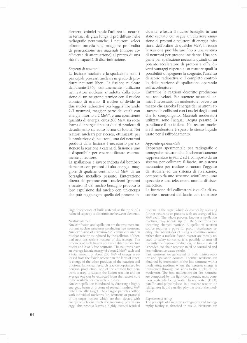
Apparato sperimentaleL’apparato sperimentale per radiografie e tomografie neutroniche è schematicamente rappresentato in fig. 2 ed è composto da un sistema per collimare il fascio, un sistema meccanico per traslare e ruotare l’oggetto da studiare ed un sistema di rivelazione, composto da uno schermo scintillante, uno specchio e una telecamera munita di siste-ma ottico.La funzione del collimatore è quella di as-sorbire i neutroni del fascio con traiettorie
large thicknesses of bulk material at the price of a reduced capacity to discriminate between elements.
Neutron sourcesNuclear fission and spallation are the two most im-portant nuclear processes producing free neutrons. Nuclear fission of uranium-235, commonly used in nuclear reactor, is induced by the collision of ther-mal neutrons with a nucleus of this isotope. The products of each fission are two lighter radioactive nuclei and 2 or 3 free neutrons. The neutrons have an average kinetic energy of about 2 MeV6 each and a total amount of about 200 MeV of energy is re-leased from the fission reaction in the form of kinet-ic energy of the other products of the reaction and photons. In nuclear research reactors, optimized for neutron production, one of the emitted free neu-trons is used to sustain the fission reaction and on average one can be extracted from the reactor core to be available for research purposes. Nuclear spallation is induced by directing a highly energetic beam of protons of several hundred MeV onto a metallic target. The charged particles collide with individual nucleons (i.e. neutrons or protons) of the target nucleus which are then ejected with energy which can reach the incoming proton en-ergy. This process leaves a highly excited residual
nucleus in the target which de-excites by releasing further neutrons or protons with an energy of few MeV each. The whole process, known as spallation reaction, may release up to 10-15 neutrons per incoming charged particle. A spallation neutron source requires a powerful proton accelerator fa-cility. The advantages of using a spallation source rather than a nuclear fission reactor are mostly re-lated to safety concerns: it is possible to turn off instantly the neutron production, no fissile material is needed, no chain reaction need be controlled and less radioactive waste results. Fast neutrons are generated in both fission reac-tor and spallation sources. Thermal neutrons are obtained by interaction of the fast neutrons with a moderating medium where the neutron energy is transferred through collisions to the nuclei of the moderator. The best moderators for fast neutrons are composed by the light compounds, most com-mon materials being water, heavy water (D2
O), paraffin and polyethylene. In a nuclear reactor the refrigerator liquid can also play the role of the mod-erator.
Experimental set-upThe principle of a neutron radiography and tomog-raphy facility is sketched in fig. 2. Neutrons are
54 55
divergenti in modo che i neutroni incida-no sul campione seguendo traiettorie il più possibile parallele, condizione necessaria per ottenere immagini radiografiche di qua-lità. Il rapporto L/D tra la lunghezza L e il diametro D del collimatore è un importante parametro che definisce il grado di collima-zione del fascio. Maggiore è il valore di L/D, migliore sarà la definizione e la nitidezza delle immagini ottenute7, al prezzo di una minore intensità di fascio utilizzabile. Il va-lore è quindi un compromesso tra due op-poste esigenze, la risoluzione spaziale che richiede un fascio collimato e il contrasto che richiede un fascio intenso.Al fine di rivelare i neutroni si utilizza uno schermo convertitore, chiamato scintillato-re, che riemette parte dell’energia trasferita dai neutroni incidenti sotto forma di luce. Il
fascio trasmesso dà quindi luogo ad un pat-tern luminoso sullo schermo che viene regi-strato per mezzo di una telecamera a CCD attraverso uno specchio, necessario per por-re la telecamera in posizione riparata dall’ir-raggiamento diretto del fascio. Il sistema ottico abbinato alla telecamera è adattato alla dimensione del campo immagine, che può variare considerevolmente a seconda dell’applicazione. Ciascun pixel del sensore CCD può essere assimilato ad un rivelato-re di neutroni indipendente che registra la luce emessa da una piccola porzione dell’a-rea dello schermo. Il segnale di tutti i pixel viene integrato per tempi abbastanza lunghi da fornire un’immagine con una buona sta-tistica, digitalizzato con un numero definito di bit, e trasferito al PC di acquisizione. Per rappresentare l’immagine acquisita, il livel-
guided from the radiation source through a col-limator to the object positioned on a manipulator system allowing handling and rotating the sample. A neutron detection system, composed by a scintil-lation converter screen, a mirror and a CCD camera coupled to optical lenses, is positioned behind the sample and measures the transmitted beam. High quality radiographies requires the path of the ra-diation particles being as parallel as possible. Col-limation is used to remove neutrons from the beam that are not traveling in nearly parallel paths. A pa-rameter useful to characterize the effectiveness of the beam collimation is the L/D ratio (L=collimator length, D=collimator diameter). The higher the L/D ratio, the better will be in terms of definition or sharpness of the image7 and the lower will be the number of neutrons reaching the object. The choice of the L/D value will be a compromise be-tween the desired image resolution and the need of producing high contrast images that require a high neutron flux. Neutrons, for radiographic applications, are usu-ally detected with a scintillation converter screen. Scintillators converts the energy transferred from incoming neutron radiation into another physical quantity, e.g. light. A CCD camera digitally records the light pattern emerging from the screen and
reflected by a mirror such that the camera can be positioned out of the beam to prevent radiation damage. Optical lenses fitted to the camera capture variably sized fields-of-view depending from appli-cation requirements. Each CCD detector element (pixel) records independently the light emitted by an area element of the converter screen. After each pixel has cumulated enough signal to create a statis-tically significant image, the data are digitized, read out and stored in the acquisition PC. To map the spatially varying neutron transmission through the object into a plane radiography, the digital signal is interpreted as a gray level, the final projection thus resulting in a black and white image.The purpose of the converter screen is to emit a light signal when crossed by a neutrons, the light intensity being proportional to the neutron in-tensity crossing the area. The screen is composed by a scintillating material embedded into a stable matrix in such a way to achieve good optical and mechanical properties and to optimize the radiation detection. Since neutrons are very difficult to de-tect by direct interaction with matter, scintillation is the result of the interaction of secondary radia-tion produced by neutron absorption in the con-verter matrix. The main features of a scintillation converter screen are: high conversion efficiency of
Fig. 2 Schema dell’apparato per radiografie e tomografie con neutroni.
Fig. 2 Layout of the neutron radiography and tomography setup.

56
lo del segnale è trasformato in una tonalità o livello di grigio e l’immagine radiografica risulta quindi in bianco e nero.Lo schermo scintillatore è formato da un materiale sensibile inserito in una matrice stabile che gli conferisce adeguate proprietà ottiche e meccaniche e ne ottimizza il mec-canismo di rivelazione. La luce prodotta non è il risultato diretto dell’interazione neu-trone-materiale scintillante, bensì il frutto di una complessa catena di interazioni tra neutrone e matrice che dà luogo a secondari carichi che interagiscono a loro volta con il materiale scintillante. Gli scintillatori han-no diverse caratteristiche vantaggiose per il loro impiego in radiografia: sono caratte-rizzati da un’alta efficienza di conversione dell’energia rilasciata dai secondari carichi in luce (alta resa di luminescenza), da una buona linearità di risposta (l’intensità della luce emessa risulta proporzionale all’ener-gia depositata), da una risposta rapida e da una buona qualità ottica che consente di realizzare scintillatori di dimensioni accet-tabili.
Risultati del progetto neu_ARTNell’ambito del progetto regionale neu_ART sono state svolte diverse campagne di mi-
sura presso due laboratori stranieri che di-spongono di un apparato per le radiografie neutroniche, INES e NECTAR. L’obiettivo delle misure è stato quello di caratterizza-re le prestazioni dei due diversi apparati in relazione all’impiego per radiografie e tomo-grafie di manufatti artistici in metallo, di va-lutare i benefici e i limiti ottenuti variando le caratteristiche dello scintillatore e della tele-camera utilizzati e di ottenere immagini ra-diografiche e ricostruzioni tomografiche di alcuni oggetti artistici. Nel seguito, dopo la descrizione degli apparati utilizzati, seguirà una rassegna dei principali risultati ottenuti.
Le facilities INES e NECTARINES, l’acronimo di Italian Neutron Expe-rimental Station8, è un apparato realizzato dal CNR per l’analisi di materiali tramite misure di diffrazione di neutroni termici e epitermici ed è situato presso la sorgente di neutroni pulsata ISIS dei laboratori Ru-therford Appleton (UK). Ad ISIS i neutroni sono prodotti per spallazione attraverso la collisione di un fascio pulsato di protoni, accelerato a 800 MeV, con un bersaglio in tungsteno e successivamente rallentati fino ad energie comprese nell’intervallo 7.8 meV – 5 eV grazie a un moderatore composto da acqua a temperatura ambiente. La sezione
radiation into light (high luminescence sensitivity), direct proportionality between the energy deposit-ed from the secondary radiation into the matrix and the light intensity emitted (good linearity), prompt reaction upon neutron absorption (fast response), good optical quality and uniformity allowing to manufacture large converter screens.
Results of the neu_ART projectIn the context of the neu_ART regional project, dif-ferent data taking have been set up in the two facili-ties, INES and NECTAR, where a neutron radiogra-phy setup was available. These measurements have been performed with the purpose of verifying the radiographic and tomographic potential on metal artifacts of the two facilities, to evaluate benefits and limits of different scintillator-camera combina-tions and to achieve some radiographic images and tomographic reconstructions of works of art. In the following, after the description of both apparatus, the main results will be presented.
The INES and NECTAR facilitiesINES, the Italian Neutron Experimental Station8, is an apparatus designed by the Italian Centro Nazio-nale delle Ricerche (CNR) for material investigations through diffraction measurements with thermal and epithermal neutrons at the ISIS neutron source of the Rutherford Appleton Laboratories (UK). At ISIS neutrons are produced by spallation through the collision of a pulsed neutron beam, accelerated up to 800 MeV, on a tungsten target. The neutrons are slowed down in the energy range 7.8 meV - 5 eV by
the usage of a water moderator operating at room temperature. The cross section of the INES beam, at the sample position, is a square of about 4x4 cm2 size with a uniform intensity of 1.1x10⁷ neutrons/cm2·s and an L/D ratio around 100. The INES facil-ity features a mechanical instrumentation, used to translate and rotate the test object and a detector, positioned at a distance between 1 and 10 cm from the object, composed by a scintillator described in the following section and a CCD camera. The latter (The Imaging Source DMK21BF04) is a low price commercial product because the radiation damage imposes frequent replacements. It is segmented in 640x480 pixels, each of them corresponding to a region of about 100x100 μm2 of the image field, and works at room temperature. Signals from each pixel are digitalized with 8 bit, corresponding to 28=256 grey levels (nominal dynamic range); the maximum integration time is 30 s. To evaluate pos-sible limits of this camera, a second CCD camera with a larger nominal dynamic range (12 bit) and with the possibility to set wider time intervals for the signal acquisition (Allied Vision Technology Manta G-032B) has been used.NECTAR, the Neutron Computerized Tomography And Radiography facility, has been designed spe-cifically for radiography and tomography with fast neutrons at the FRMII research reactor of the Tech-nical University of Munich (Germany). Fast neu-trons are produced by fission on two uranium en-riched converters positioned at 1 m distance from the reactor core, inside the moderator tank and are carefully collimated to reach an L/D ratio about
56 57
del fascio di INES, in corrispondenza del campione, è un quadrato di circa 4x4 cm2 con un’intensità uniforme di circa 1.1x10⁷ neutroni/cm2s e un rapporto L/D≈100. L’ap-parato dispone di un manipolatore per tra-slare e ruotare l’oggetto da analizzare e di un rivelatore, posto a distanze comprese tra 1 e 10 cm dall’oggetto, composto da uno scintillatore, descritto nel paragrafo che se-gue, e da una telecamera CCD. Quest’ulti-ma (The Imaging Source DMK21BF04), un prodotto commerciale a basso costo a causa della frequente sostituzione per il danneg-giamento da radiazione, è segmentata in 640x480 pixel, ciascuno corrispondente a una porzione di circa 100x100 mm2 del campo immagine, ed è progettata per la-vorare a temperatura ambiente. Il segnale di ogni pixel è digitalizzato con 8 bit che consentono di codificare fino a 28=256 li-velli di grigio (range dinamico nominale); il massimo tempo di integrazione è di 30 s. Al fine di determinare i limiti imposti della telecamera utilizzata ad INES, una secon-da telecamera CCD con un range dinamico nominale superiore (12 bit) e la possibilità di integrare il segnale per tempi più lunghi (Allied Vision Technology Manta G-032B) è stata anche utilizzata per confronto.NECTAR, acronimo di Neutron Compu-
terized Tomography And Radiography, è un apparato disegnato espressamente per radiografie e tomografie neutroniche con neutroni veloci presso il reattore di ricerca FRMII dell’Università Tecnica di Monaco in Germania. I neutroni veloci sono pro-dotti per fissione grazie a due convertitori in uranio arricchito posti a 1 m di distan-za dal nocciolo del reattore, all’interno del moderatore, e opportunamente collimati per ottenere un rapporto L/D≈300. Oltre al collimatore, lungo la linea di estrazione è presente un filtro in cadmio per assorbire i neutroni termici provenienti dal reattore e un filtro in piombo per ridurre la conta-minazione di fotoni di alta energia prodotti nel processo di fissione. La sezione trasver-sa del fascio in corrispondenza del cam-pione è un rettangolo 37x31 cm2 con una intensità media di 5.4x10⁵ neutroni/cm2s e un’energia media per neutrone di 1.7 MeV. Come nel caso precedente, è presente un manipolatore per traslare e ruotare l’ogget-to da analizzare e un sistema di rivelazione con uno schermo scintillante. La telecamera CCD è una ANDOR DV434-BV a basso ru-more, sviluppata per applicazioni in astro-nomia, che opera raffreddata con celle di Peltier. Il campo immagine è segmentato in 1024x1024 pixel, ciascuno corrisponden-
300. Moreover two filters made of cadmium and lead are added to absorb respectively thermal neu-trons coming from the reactor and high energy pho-tons produced during the fission process. The beam transverse section at the sample position is a square of 37x31 cm2 with an average intensity of 5.4x10⁵ neutrons/cm2·s and 1.7 MeV mean neutron energy. Also in this facility a translator and a rotary stage for the test object handling and a detection system with a scintillator screen are available. The CCD is a low noise camera ANDOR DV434-BV, developed for astronomy applications, cooled by Peltier cells. It is segmented in 1024x1024 pixels, each of them corresponding to 300x300 μm2 of the image field. The nominal dynamic range is 16 bit and it is pos-sible to integrate the signal up to a time of 2000 s.
Properties of the analyzed scintillators The choice of a scintillator for a radiographic set-up depends on the mean energy of the neutron beam and on the instrumentation used to acquire the image. Moreover both the neutron conversion efficiency and the image resolution are strongly related to the thickness of the scintillator screen. One of the main studies performed in the two neu-tron facilities has been the comparison of differ-ent scintillators. They have been properly selected based on the properties described in the following, with the aim of highlighting their detection poten-tial for this kind of application.Both organic and inorganic scintillators have been tested. Inorganic scintillators, as the zinc sulfide silver doped ZnS(Ag) and the gadolinium oxisul-
fide doped with terbium Gd2O
2S:Tb, have a good
neutron conversion’s efficiency and therefore are reliable for low neutron flux applications. How-ever they can’t give prompt signals. For these ma-terials the scintillation mechanism relies on the energy levels of the crystal lattice and on the pres-ence of impurities embedded into it. Conversely, organic scintillators have a faster response which makes them suitable for imaging purposes. Un-fortunately they suffer of a very low luminescence power and so they need of high neutron fluxes. In this case the scintillation mechanism is due to the fluorescence of the material itself.In the following the main properties of the tested scintillators are reported.
INESThermal neutron screen NDG (Applied Scintillation Technology) - It is composed by ZnS(Ag) mixed with lithium fluoride 6LiF with a relative weight of 2:1. The lithium fluoride is added to the zinc sulfide because it has an extremely high thermal neutron cross section (940 barn). The interac-tion between neutrons with a lithium-6 nucleus produces a tritium nucleus and an alpha particle which in turn interacts with the zinc sulfide gen-erating scintillation light. Two versions of this scintillator have been tested to evaluate the image resolution and dynamic range dependence on the screen thickness and on the possible presence of a plastic matrix. The scintillation material in the first scintillator type is inserted in a plastic matrix of 450 μm thickness while in the second one is
58
te a 300x300 mm2 del campo immagine. Il range dinamico nominale della telecamera è di 16 bit e il segnale può essere integrato per tempi molto lunghi, fino a 2000 s.
Caratteristiche degli scintillatori analizzatiLa scelta dello scintillatore per un apparato radiografico dipende dall’energia dei neu-troni e dal tipo di rivelatore utilizzato per registrare l’immagine. Inoltre lo spessore dello schermo influisce sia sull’efficienza di conversione sia sulla risoluzione dell’im-magine. Nell’ambito delle misure effettuate presso i due laboratori si è voluto operare un confronto fra diversi scintillatori, scelti in modo ragionato in base alle caratteristiche dettagliate nel seguito, al fine di verificarne le caratteristiche per questo tipo di applica-zione. Gli scintillatori scelti sono sia a base di com-posti inorganici sia a base di composti or-ganici. Gli scintillatori inorganici, quali il solfuro di zinco attivato all’argento ZnS(Ag) e l’ossisolfuro di gadolinio attivato al terbio Gd
2O
2S:Tb, hanno miglior resa di lumine-
scenza e sono pertanto adatti ad applica-zioni con bassi flussi di neutroni, ma sono lenti nel tempo di risposta. In questi mate-riali il meccanismo di scintillazione è legato agli stati di energia del reticolo cristallino e alla presenza di impurità introdotte ad hoc all’interno dello stesso. Gli scintillatori or-ganici, quali quelli a base di toluene, sono al contrario più veloci, caratteristica che li rende preferibili in applicazioni di imaging,
ma hanno una bassa resa di luminescenza e richiedono pertanto alti flussi di neutroni incidenti. In questo caso il meccanismo di scintillazione è la fluorescenza del materiale utilizzato. Di seguito sono riportate le caratteristiche degli scintillatori utilizzati.
INES Thermal neutron screen NDG (Applied Scintil-lation Technology) – Il materiale scintillante è un composto di ZnS(Ag) miscelato con del fluoruro di litio 6LiF in un rapporto in peso di due parti a uno. Il fluoruro di litio è aggiunto al solfuro di zinco perché presenta un’elevata sezione d’urto di interazione con i neutroni termici (940 barn). L’interazione del neutrone con il litio-6 genera un nu-cleo di trizio ed una particella alfa che, in-teragendo con il solfuro di zinco, generano luce di scintillazione. Sono state testate due versioni di questo scintillatore per valutare l’effetto dello spessore e della presenza della matrice plastica sulla risoluzione e sul range dinamico dell’immagine finale: la prima con materiale scintillante inserito in una matrice plastica con spessore totale di 450 mm, la se-conda con materiale scintillante depositato su di un substrato di 1 mm di alluminio per uno spessore di 250 mm.
NECTAR ZnS(Ag) in matrice di polipropilene, spessore 2mm - È lo scintillatore in uso presso NEC-TAR ed è stato caratterizzato per avere figure
deposited on a thin aluminum layer of 1 mm with a total thickness of 250 μm.
NECTARZnS(Ag) in polypropylene matrix, thickness 2mm - This is the neutron converter actually used in the NECTAR facility and it has been characterized in order to have a reference point for the other scintil-lators. The scintillating material is ZnS(Ag) and the luminescence is due to charged particles generated by the interactions between neutrons and nucleus of the polypropylene matrix elements.Thermal neutron screen NDG (Applied Scintillation Technology) - It is the scintillator ZnS(Ag):6LiF em-bedded in plastic matrix, 450 μm thick, used at INES. Since it is composed by the same scintillation material of the NECTAR converter screen in a thin-ner layer, it allows to check the dependence of reso-lution on scintillator thickness with fast neutrons.Plastic scintillators (EJ200 EJ212 Eljen Technology) - The main interaction mechanism of fast neutrons with matter is the elastic collision with a hydrogen nucleus and for this reason plastic neutron convert-ers are suitable for their detection. They are com-posed by poliviniltoluene, an organic scintillator with a very fast response which makes them partic-ularly recommended for radiographic applications.
Two converter screens have been tested, both with a thickness of 20 mm. The first one, EJ200, is the best general purpose organic scintillator because it detects almost all types of radiation fields with a high converter efficiency and an extremely good transparency to its own scintillation light, allow-ing for layers of very large size. The second, EJ212, is the plastic scintillator mostly used for fast neu-tron detection in nuclear physics. Unlike the EJ200 screen, it is not sensitive to high-energy gamma rays even though the poliviniltoluene is its main com-pound. This makes it more suitable for applications where the neutrons to detect are in a mixed neu-tron-gamma field, as in the NECTAR facility.Agfa Curix Ortho Regular X-ray converter screen - They are commonly used as support screens in the traditional X-ray radiography where they are in-serted into the radiographic case together with the sensitive film. They are composed by gadolinium oxifluoride activated with terbium (Gd
2O
2S:Tb), an
inorganic scintillator. The gadolinium has a high cross section for thermal neutrons which remains still significant (around 10 barn for the main iso-tope) for neutrons of 1 MeV energy. They are avail-able as consumer items at a moderate price, also in big sizes. This fact, together with the small thick-ness of 1 mm, makes them particularly indicated
58 59
di merito di riferimento per gli altri scintil-latori. Il materiale scintillante è ZnS(Ag) e la luminescenza è causata dai secondari ca-richi prodotti dall’interazione tra i neutro-ni e i nuclei degli elementi della matrice di polipropilene.Thermal neutron screen NDG (Applied Scintil-lation Technology) – È lo stesso scintillatore ZnS(Ag):6LiF in matrice plastica spessa 450 mm utilizzato ad INES che, essendo compo-sto dello stesso materiale scintillante dello schermo presente a NECTAR in uno strato più sottile, consente di verificare con neu-troni veloci la dipendenza della risoluzione dallo spessore dello scintillatore.Scintillatori plastici (EJ200 EJ212 Eljen Technology) – Per i neutroni veloci il princi-pale meccanismo di interazione con la ma-teria è l’urto elastico con nuclei di idrogeno, e per questo motivo gli scintillatori plastici risultano particolarmente adatti per la loro rivelazione. Il materiale di cui sono costituiti è poliviniltoluene, uno scintillatore organi-co che ha una risposta molto rapida che lo rende particolarmente adatto alle applica-zioni del progetto. Sono stati impiegati due schermi, entrambi spessi 20 mm. Il primo, EJ200, è il miglior scintillatore organico per impieghi generici in quanto risponde a tutti i tipi di radiazione, presenta una elevata resa di luminescenza ed una elevata trasparenza alla propria luce di scintillazione che con-sente di realizzare lastre anche di grandi di-mensioni. Il secondo, EJ212, è lo scintillato-re plastico comunemente utilizzato per rive-
lare neutroni veloci in applicazioni di fisica nucleare. È costituito anch’esso in gran par-te da poliviniltoluene ma rispetto all’EJ200 è insensibile ai fotoni gamma di energia eleva-ta, cosa che lo rende particolarmente adatto in applicazioni in cui i neutroni da rivelare sono in un campo misto neutroni-gamma, come quello di NECTAR.Agfa Curix Ortho Regular X-ray converter screen - Nella radiologia X tradizionale sono ampiamente conosciuti e utilizzati schermi di rinforzo che vengono inseriti nella casset-ta radiografica insieme alla pellicola. L’Agfa Curix Regular è uno schermo di rinforzo alle terre rare contenente ossisulfuro di ga-dolinio attivato al terbio (Gd
2O
2S:Tb), uno
scintillatore inorganico. Il gadolinio presen-ta una sezione d’urto di cattura elevata per neutroni termici, che comunque risulta es-sere ancora importante, intorno ai 10 barn per l’isotopo più abbondante, per i neutroni di energia dell’ordine del MeV. Tali schermi sono disponibili come materiale di consumo a costi contenuti, anche in grandi dimen-sioni. Tutte queste caratteristiche unite allo spessore limitato di circa 1 mm, lo rendo-no particolarmente degno di attenzione per una caratterizzazione approfondita presso NECTAR.
Risultati: linearità, risoluzione e range dinamicoPer lo studio della linearità dei diversi si-stemi di imaging (scintillatore e telecamera) sono state registrate ad INES e NECTAR im-
for an in-depth characterization at the NECTAR facility.
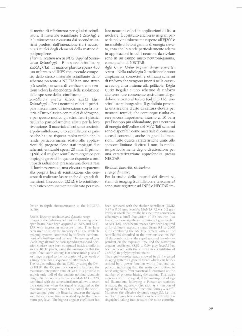
Results: linearity, resolution and dynamic rangeImages of the radiation field, in the following called open beam, have been acquired at INES and NEC-TAR with increasing exposure times. They have been used to study the linearity of all the available imaging systems composed by different combina-tions of scintillator and camera. The average of grey levels (signal) and the corresponding standard devi-ation (noise) have been computed inside a uniform area of 10x10 pixels, using the assumption that the signal fluctuation among 100 consecutive pixels of an image is equal to the fluctuation of grey levels of a single pixel for a sequence of 100 images.The results indicate that at INES, by using the DM-K21BF04, the 450 μm thickness scintillator and the maximum integration time of 30 s, it is possible to exploit only half of the camera nominal dynamic range. On the contrary the camera MANTA G-0328, combined with the same scintillator, allows to reach the saturation when the signal is acquired at the maximum exposure time of 60 s. For all the scintil-lator-camera pairs the linearity between the signal and the exposure time is verified up to the maxi-mum grey level. The highest angular coefficient has
been achieved with the thicker scintillator (DMK: 3.77 ± 0.03 grey levels/s; MANTA 72.4 ± 0.2 grey levels/s) which features the best neutron conversion efficiency: a small fluctuation of the neutron flux leads to a more significant variation of grey levels.At NECTAR, open beam images have been acquired at for different exposure times (from 0.1 to 2000 s) by combining the ANDOR camera with all the scintillators described in the previous section. For all the combinations, the signal resulted linearly de-pendent on the exposure time and the maximum angular coefficient (8.82 ± 0.04 grey level/s) has been achieved with the 2 mm thick scintillator of ZnS(Ag) in polypropylene matrix.The signal-to-noise study showed in all the tested imaging systems a general trend which can be de-scribed by a power function with a fractional ex-ponent, indicating that the main contribution to noise originates from statistical fluctuations on the number of photons hitting the camera. This noise increases with the signal; if the assumption of sig-nal fluctuations following a Poissonian statistics is made, the signal-to-noise ratio as a function of signal should follow the functional form y = A·x0.5.Moreover the effective dynamic range (L), i.e. the number of grey levels which can be effectively dis-tinguished taking into account the noise contribu-
60
magini del campo di radiazione, nel seguito chiamate open beam, variando il tempo di integrazione del segnale. L’analisi delle im-magini è stata fatta calcolando su ciascuna di esse il valor medio dei livelli di grigio dei pixel (segnale) e la relativa deviazione standard (rumore), su una regione di 10x10 pixel, sotto l’ipotesi che la fluttuazione del segnale tra 100 pixel adiacenti di una singo-la immagine sia equivalente alla fluttuazione dei livelli di grigio del singolo pixel in 100 immagini acquisite in tempi successivi.I risultati indicano che a INES, utilizzando la telecamera DMK21BF04, lo scintillatore spesso 450 mm ed integrando il segnale per il tempo massimo consentito di 30 s, si rie-sce a sfruttare solo metà del range dinamico nominale della telecamera. Al contrario, con la telecamera MANTA G-032B accoppiata allo stesso scintillatore si raggiunge la sa-turazione quando il segnale viene integrato
per il tempo massimo di 60 s. Per tutte le combinazioni l’andamento del segnale in funzione del tempo di integrazione risulta lineare fino alla saturazione con una pen-denza maggiore quando si utilizza lo scin-tillatore più spesso da 450 mm (DMK: 3.77 ± 0.03 livello di grigio/s; MANTA 72.4 ± 0.2 livello di grigio/s), ad indicare una mi-gliore efficienza di conversione: una piccola variazione del flusso di neutroni comporta quindi una maggiore variazione dei livelli di grigio. Presso NECTAR le immagini di open beam sono state ottenute combinando la teleca-mera ANDOR con gli scintillatori descritti nella sezione precedente e variando il tempo di integrazione del segnale da 0.1 s a 2000 s. In tutti i casi è stata verificata la linearità del segnale in funzione del tempo di integrazio-ne con la pendenza massima (8.82 ± 0.04 li-vello di grigio/s) con lo scintillatore ZnS(Ag)
tion, has been computed for all the camera-scin-tillator combinations. L is related to signal (S) and noise (N) by the equation:
L= ∫ b
where a and b are respectively the highest and the lowest limit of the available signal range. Com-parisons between the different imaging systems have been performed with the same exposure time (fig. 3) because, as mentioned above, the dy-namic range increases with the integration time. The INES highest dynamic range (80 effective grey levels) corresponds to the combination MANTA camera – 450 μm thickness scintillator. At NEC-TAR the ZnS(Ag) scintillator in polypropylene ma-trix with a thickness of 2 mm and the two plastic scintillators EJ200 EJ212 have a similar behavior achieving respectively 123 ± 7, 110 ± 5, 124± 6 effective grey levels at the exposure time of 2000 s.The spatial resolution, expressed in terms of FWHM, has been computed for all the imaging systems by using the image of a sharp edge as de-scribed in the literature9. At INES, the best spa-
tial resolution (182 ± 11 μm) has been obtained with the DMK camera combined with the thinner scintillator of 250 μm. At NECTAR the best spatial resolution (659 ± 7 μm) has been achieved with the thermal neutron screen NDG of 450 μm thick-ness; this value is larger than the resolution ob-tained at INES with the same scintillator. In fact, although the spatial resolution is related to the L/D ratio (the higher is L/D, the lower is the spatial resolution) and this ratio is higher at NECTAR, each pixel at INES corresponds to 100x100 μm2 of the image field compared to 300x300 μm2 at NECTAR. By using the 2 mm thickness ZnS(Ag) scintillator in polypropylene matrix, it is possible to solve at NECTAR details of 900 μm; however this spatial resolution worsens up to 2 mm with the two plastic scintillators because of their large thickness.Finally, the characterization has been completed with a neutron radiography of step wedges of bronze, brass, steel, aluminum and PET manufac-tured on purpose for this analysis. For all the com-binations camera-scintillator the beam intensity attenuation has been studied as a function of the
Fig. 3 Livelli di grigio effettivi in funzione del tempo di integrazione del segnale per le diverse combinazioni CCD – scintillatore. A sinistra: risultati ottenuti ad INES (scintillator 1 = Thermal neutron screen NDG 250 mm; scintillator 2 = Thermal neutron screen NDG 450 mm); a destra: risultati ottenuti a NECTAR (1=ZnS(Ag) in matrice di polipropilene spessore 2mm, 2=Thermal neutron screen NDG 450 mm; 3= Agfa Curix Ortho Regular X-ray converter screen; 4= Scintillatore plastico EJ200 5=Scintillatore plastico EJ212).
Fig. 3 Number of effective grey levels as a function of the signal integration time for different combinations CCD-scintillator. On the left: results of INES (scintillator 1=Thermal neutron screen NDG 250 μm; scintillator 2=Thermal neutron screen NDG 450 μm). On the right: results obtained at NECTAR (1=ZnS(Ag) thicknes 2mm; 2=Thermal neutron screen NDG 450 μm; 3=Agfa Curix Ortho Regular X-ray converter screen; 4=plastic scintillator EJ200; 5=plastic scintillator EJ212).
a
dsN(s)
60 61
in matrice di polipropilene spesso 2mm. Lo studio del segnale/rumore in funzione del segnale ha rivelato in tutti i sistemi testati un andamento che può essere approssimato con una potenza ad esponente frazionario. Questo indica che il contributo principale al rumore deriva dalle fluttuazioni statistiche dei fotoni che colpiscono la telecamera e quindi aumenta al crescere del segnale; in-fatti assumendo che le fluttuazioni seguano la statistica di Poisson, l’andamento segnale/rumore in funzione del segnale dovrebbe avere un andamento tipo y = A·x0.5.Per tutte le diverse combinazioni teleca-mera-scintillatore è stato poi determinato il range dinamico effettivo (L), ovvero il numero di livelli di grigio effettivamente distinguibili tenendo conto del rumore. L dipende dal segnale S e dal rumore N attra-verso la relazione:
L= ∫ b
dove a e b sono rispettivamente il limite inferiore e superiore del range del segnale utile. Dal momento che il range dinamico aumenta al crescere del tempo di integra-zione i confronti tra i diversi sistemi di imaging sono stati fatti a parità di tempo di integrazione del segnale (fig. 3). Per INES il range dinamico più elevato (80 livelli di grigio effettivi) si ottiene utilizzando la telecamera MANTAG-032B con lo scintil-latore più spesso da 450 nm. Presso NEC-TAR lo scintillatore ZnS(Ag) in matrice di polipropilene spesso 2mm e i due scintil-latori plastici EJ200 EJ212 risultano ave-
re comportamenti confrontabili raggiun-gendo rispettivamente 123 ± 7, 110 ± 5, 124± 6 livelli di grigio effettivi per 2000 s di esposizione.Infine, la caratterizzazione dei sistemi di imaging è stata completata con la determi-nazione della risoluzione spaziale, in termi-ni di FWHM, usando l’immagine di un bor-do netto di un sottile materiale radiopaco9. Per INES la risoluzione spaziale migliore (182 ± 11) mm è stata ottenuta con la tele-camera DMK abbinata allo scintillatore più sottile di 250 nm. Per quanto riguarda NEC-TAR la risoluzione spaziale migliore (659 ± 7) mm è stata ottenuta con lo scintillatore Thermal neutron screen NDG da 450 mm. Questo valore risulta circa il doppio rispetto a quello ottenuto ad INES con il medesimo scintillatore. Infatti, sebbene la risoluzione spaziale sia strettamente legata al rapporto L/D (maggiore è L/D, minore è la risolu-zione spaziale) e questo rapporto sia molto superiore a NECTAR rispetto ad INES (cir-ca 300 vs circa 90), bisogna ricordare che ad INES ciascun pixel corrisponde circa a 100x100 mm2 del campo immagine mentre a NECTAR ciascun pixel corrisponde a circa 300x300 mm2. Presso NECTAR, se si utilizza lo scintillatore ZnS(Ag) in matrice di poli-propilene dello spessore di 2 mm si riesco-no a risolvere dimensioni dell’ordine di 900 mm, mentre la risoluzione spaziale peggiora fino a circa 2 mm utilizzando i due scintilla-tori plastici a causa del loro elevato spessore.Per completare la caratterizzazione dei si-stemi di imaging sono state radiografate delle scalette opportunamente realizzate in
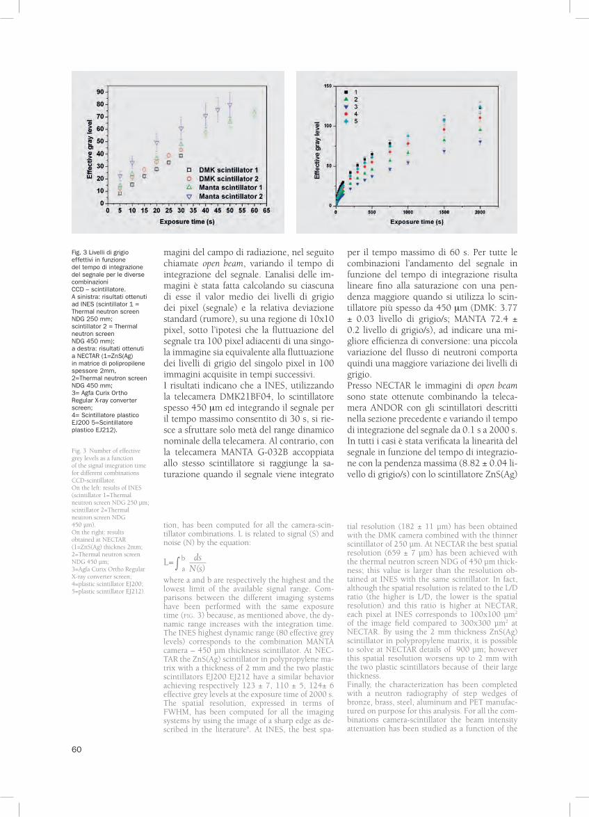
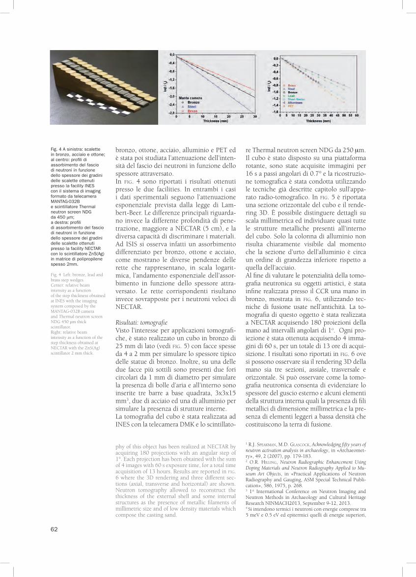
thickness of material. figure 4 shows the results obtained at INES and NECTAR. In both cases the experimental data follow the exponential attenua-tion Lambert-Beer’s law, the main difference being the maximum beam penetration depth which is higher at NECTAR (5mm), and the different el-emental separation potential. This can be clearly observed at INES where the different beam at-tenuation of bronze, brass and steel is clearly evi-denced by the angular coefficients of the straight lines which represent, in logarithmic scale, the exponential behavior of the beam attenuation as a function of the material depth. These straight lines are hardly distinguishable at NECTAR.
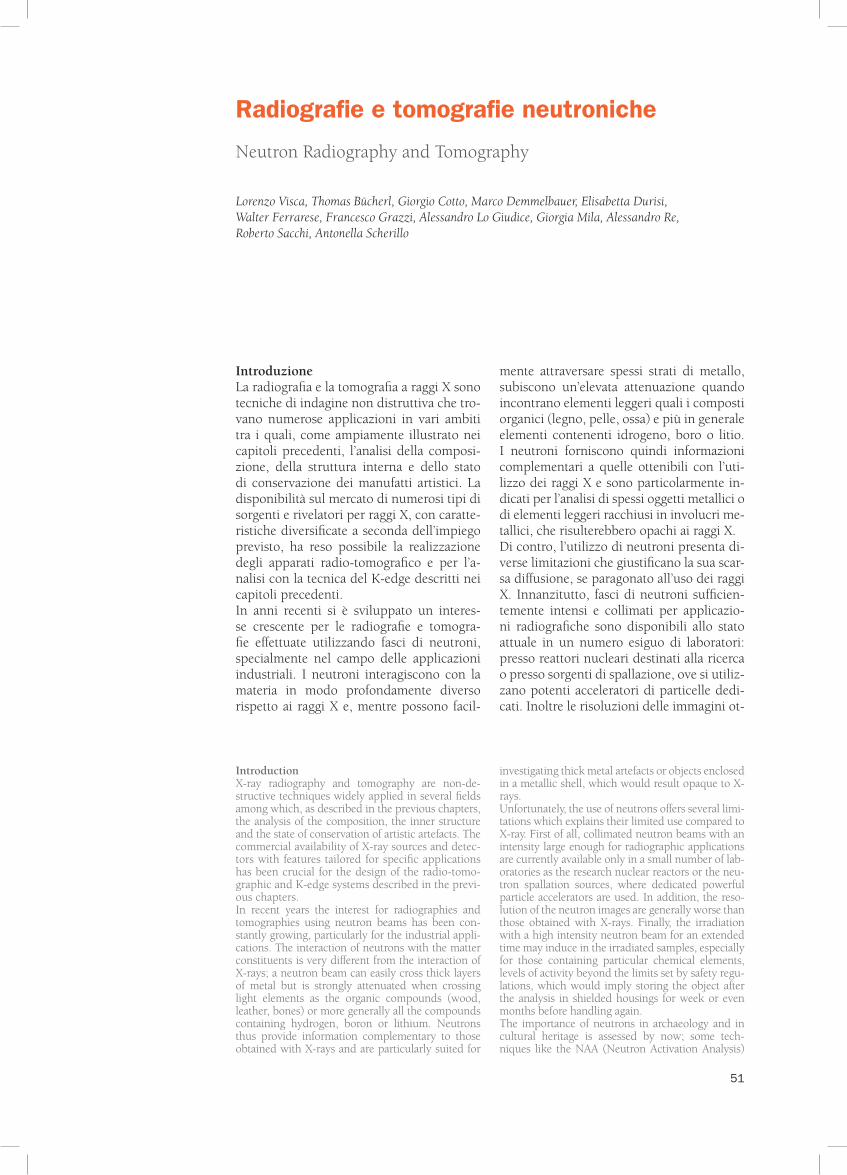
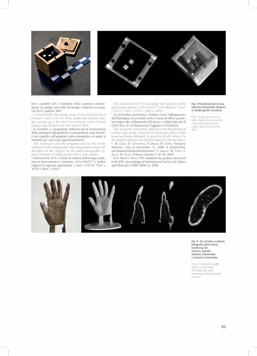
Results: tomographiesGiven the increasing interest for neutron tomo-graphic applications, a bronze cube of 25 mm side (fig. 5) has been realized with faces of dif-ferent thickness, ranging from 4 to 2 mm which correspond to the typical thickness of bronze stat-ues. Moreover two bronze rods and one of alu-minum with square section of 3x3 mm2 and 15 mm height, have been inserted inside the cube
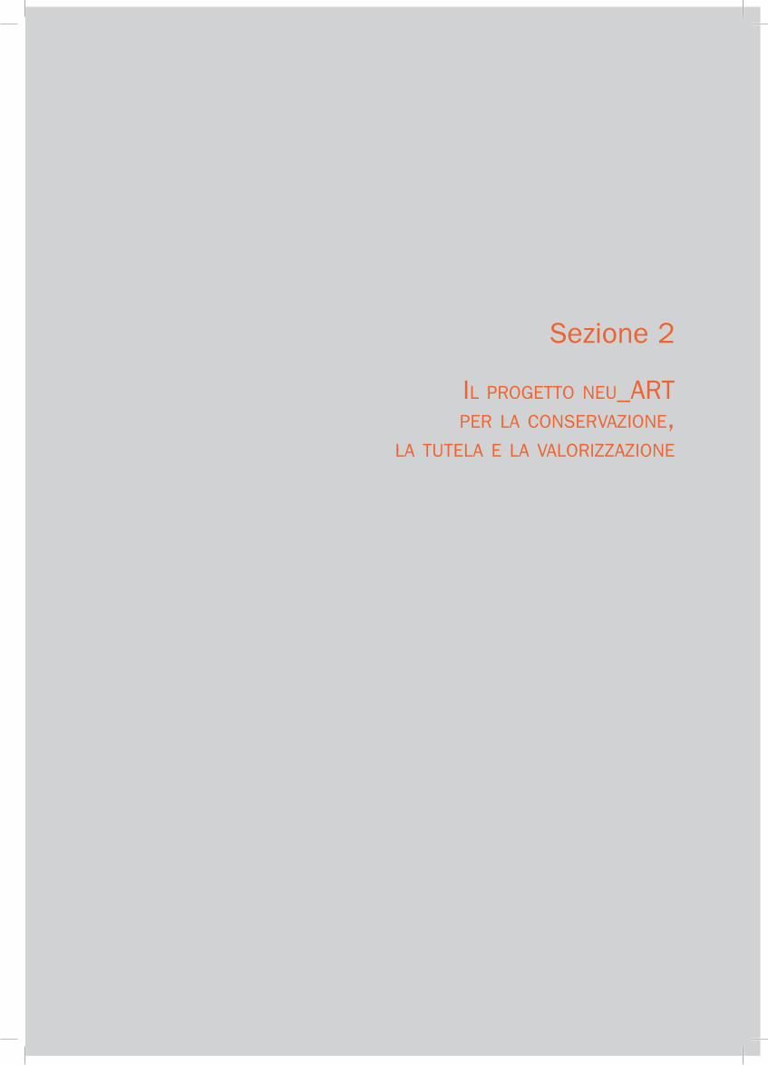
together with two circular drills of 1 mm diam-eter in its thinner face to simulate respectively the presence of internal structures and metal casting air bubbles. The tomography of the cube has been performed at INES with the DMK camera and the thermal neutron screen NDG of 250 μm thick-ness. The cube has been positioned on a rotary stage and the angular step has been set to 0.7°. Images have been acquired with an exposure time of 16 s. The tomographic reconstruction has been performed by the usage of the techniques already described in chapter on the radio-tomographic ap-paratus. In fig. 5 a horizontal section of the cube and the 3D rendering are shown. It is evident from the reconstructed section that it is possible to re-solve details of a millimetric scale and to locate all the metallic structures inside the cube. Only the aluminum rod is not easily visible because of the cross section which is about one order of magni-tude lower for aluminum than for steel.Finally, a bronze hand, shown in fig. 6, has been prepared at the CCR, using ancient techniques of metal artifact casting, to evaluate the neutron to-mography potential on works of art. The tomogra-
a
dsN(s)
62
bronzo, ottone, acciaio, alluminio e PET ed è stata poi studiata l’attenuazione dell’inten-sità del fascio dei neutroni in funzione dello spessore attraversato. In fig. 4 sono riportati i risultati ottenuti presso le due facilities. In entrambi i casi i dati sperimentali seguono l’attenuazione esponenziale prevista dalla legge di Lam-bert-Beer. Le differenze principali riguarda-no invece la differente profondità di pene-trazione, maggiore a NECTAR (5 cm), e la diversa capacità di discriminare i materiali. Ad ISIS si osserva infatti un assorbimento differenziato per bronzo, ottone e acciaio, come mostrano le diverse pendenze delle rette che rappresentano, in scala logarit-mica, l’andamento esponenziale dell’assor-bimento in funzione dello spessore attra-versato. Le rette corrispondenti risultano invece sovrapposte per i neutroni veloci di NECTAR.
Risultati: tomografieVisto l’interesse per applicazioni tomografi-che, è stato realizzato un cubo in bronzo di 25 mm di lato (vedi fig. 5) con facce spesse da 4 a 2 mm per simulare lo spessore tipico delle statue di bronzo. Inoltre, su una delle due facce più sottili sono presenti due fori circolari da 1 mm di diametro per simulare la presenza di bolle d’aria e all’interno sono inserite tre barre a base quadrata, 3x3x15 mm3, due di acciaio ed una di alluminio per simulare la presenza di strutture interne. La tomografia del cubo è stata realizzata ad INES con la telecamera DMK e lo scintillato-
re Thermal neutron screen NDG da 250 mm. Il cubo è stato disposto su una piattaforma rotante, sono state acquisite immagini per 16 s a passi angolari di 0.7° e la ricostruzio-ne tomografica è stata condotta utilizzando le tecniche già descritte capitolo sull’appa-rato radio-tomografico. In fig. 5 è riportata una sezione orizzontale del cubo e il rende-ring 3D. È possibile distinguere dettagli su scala millimetrica ed individuare quasi tutte le strutture metalliche presenti all’interno del cubo. Solo la colonna di alluminio non risulta chiaramente visibile dal momento che la sezione d’urto dell’alluminio è circa un ordine di grandezza inferiore rispetto a quella dell’acciaio.Al fine di valutare le potenzialità della tomo-grafia neutronica su oggetti artistici, è stata infine realizzata presso il CCR una mano in bronzo, mostrata in fig. 6, utilizzando tec-niche di fusione usate nell’antichità. La to-mografia di questo oggetto è stata realizzata a NECTAR acquisendo 180 proiezioni della mano ad intervalli angolari di 1o. Ogni pro-iezione è stata ottenuta acquisendo 4 imma-gini di 60 s, per un totale di 13 ore di acqui-sizione. I risultati sono riportati in fig. 6 ove si possono osservare sia il rendering 3D della mano sia tre sezioni, assiale, trasversale e orizzontale. Si può osservare come la tomo-grafia neutronica consenta di evidenziare lo spessore del guscio esterno e alcuni elementi della struttura interna quali la presenza di fili metallici di dimensione millimetrica e la pre-senza di elementi leggeri a bassa densità che costituiscono la terra di fusione.
1 R.J. Speakman, M.D. glaScock, Acknowledging fifty years of neutron activation analysis in archaeology, in «Archaeomet-ry», 49, 2 (2007), pp. 179-183. 2 O.R. Hilling, Neutron Radiographic Enhancement Using Doping Materials and Neutron Radiography Applied to Mu-seum Art Objects, in «Practical Applications of Neutron Radiography and Gauging, ASM Special Technical Publi-cation», 586, 1975, p. 268.3 1st International Conference on Neutron Imaging and Neutron Methods in Archaeology and Cultural Heritage Research NINMACH2013, September 9-12, 2013. 4 Si intendono termici i neutroni con energie comprese tra 5 meV e 0.5 eV ed epitermici quelli di energie superiori,
phy of this object has been realized at NECTAR by acquiring 180 projections with an angular step of 1°. Each projection has been obtained with the sum of 4 images with 60 s exposure time, for a total time acquisition of 13 hours. Results are reported in fig. 6 where the 3D rendering and three different sec-tions (axial, transverse and horizontal) are shown. Neutron tomography allowed to reconstruct the thickness of the external shell and some internal structures as the presence of metallic filaments of millimetric size and of low density materials which compose the casting sand.
Fig. 4 A sinistra: scalette in bronzo, acciaio e ottone; al centro: profili di assorbimento del fascio di neutroni in funzione dello spessore dei gradini delle scalette ottenuti presso la facility INES con il sistema di imaging formato da telecamera MANTAG-032B e scintillatore Thermal neutron screen NDG da 450 μm; a destra: profili di assorbimento del fascio di neutroni in funzione dello spessore dei gradini delle scalette ottenuti presso la facility NECTAR con lo scintillatore ZnS(Ag) in matrice di polipropilene spesso 2mm.
Fig. 4 Left: bronze, lead and brass step wedges. Center: relative beam intensity as a function of the step thickness obtained at INES with the imaging system composed by the MANTAG-032B camera and Thermal neutron screen NDG 450 μm thick scintillator. Right: relative beam intensity as a function of the step thickness obtained at NECTAR with the ZnS(Ag) scintillator 2 mm thick.
62 63
Fig. 6 Da sinistra a destra: fotografia della mano, rendering 3D, sezione assiale, sezione trasversale e sezione orizzontale.
Fig. 6 From left to right: picture of the hand, 3D rendering, axial, transversal and horizontal sections.
Fig. 5 Ricostruzione di una sezione orizzontale (destra) e rendering 3D (sinistra).
Fig. 5 Left: picture of the cube. Right: reconstruction of an horizontal section (right) and 3D rendering (left).
fino a qualche keV. I neutroni veloci coprono comune-mente un ampio intervallo di energie compreso tra qual-che keV e qualche MeV. Conventionally, the energy range of thermal neutrons is between 5 meV e 0.5 eV while epithermal neutron ener-gies extend up to few keV. Fast neutrons cover a broad energy range between few keV and few MeV. 5 Le tecniche e i programmi utilizzati per la ricostruzioni delle immagini radiografiche e tomografiche sono descrit-ti nel capitolo sull’apparato radio-tomografico al quale si rimanda per i necessari approfondimenti. The techniques and the programs used for the recon-struction of the radiographic and tomographic images are described in the chapter on the radio-tomographic sy-stem; for further reading please refer to that chapter.6 L’elettronvolt (eV) è l’unità di misura dell’energia utiliz-zata in fisica atomica e nucleare; 1eV=1.6x10⁻¹⁹ J. Inoltre valgono le seguenti equivalenze: 1 meV = 10-3eV, 1 keV = 103eV, 1 MeV = 106eV
The electronvolt (eV) is an energy unit used in atomic and nuclear physics; 1eV=1.6x10⁻¹⁹ J. In addition, 1 meV = 10-3eV, 1 keV = 103eV, 1 MeV = 106eV7 La penombra geometrica, definita come l’allargamento dell’immagine di un bordo netto a causa di effetti geome-trici legati alla collimazione del fascio, è infatti data da d/(L/D) dove d è la distanza tra l’oggetto e il rivelatore. The geometric penumbra, defined as the broadening of a sharp edge image caused by the geometric effects of the beam not being collimated, is given by d/(L/D) where d is the distance between the neutron detector and the object.8 M. celli, D. cologneSi, f. grazzi, m. zoppi, Notiziario Neutroni e Luce di Sincrotrone, 11, 2006, 6 (http://www.cnr.it/neutronielucedisincrotrone); F. grazzi, m. celli, S. Siano, m. zoppi, Il Nuovo Cimento C 30, 59, 2007.9 E.H. Barney SmitH, PSF estimation by gradient descent fit to the ESF, proceedings of International Society for Optics and Photonics (SPIE) 6059, E, 2006.

64
64 65
Il progetto neu_Art per lA conservAzIone,
lA tutelA e lA vAlorIzzAzIone
Sezione 2

66