Embed Size (px)
Citation preview
Radiation Safety, CT Dose Optimization and Safe
Procedures for CT Technologists’
Sven Gallo M.Sc., CRE, RSO
Diagnostic Medical Physicist
ProMedica Health System
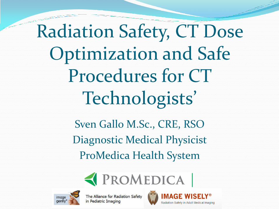
Joint Commission Requirement
• This training must be completed annually by all CT Technologists’ • This will be followed by a post test
CT Radiation Dose CT Components
Radiation Quantities and Dosimetry?
Why is Radiation Dose an issue?
Radiation dose optimization techniques for pediatrics and adults
Are newborns and kids more sensitive to radiation when compared to adults?
What resources and technology do we have available; where radiation dose can be optimized and lowered?
Pregnancy and Shielding
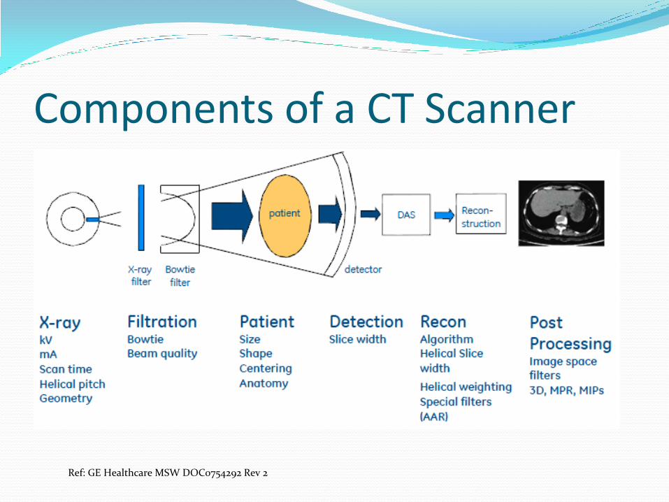
Components of a CT Scanner
Ref: GE Healthcare MSW DOC0754292 Rev 2
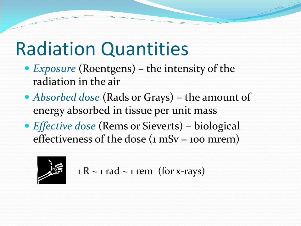
Radiation Quantities Exposure (Roentgens) – the intensity of the
radiation in the air
Absorbed dose (Rads or Grays) – the amount of energy absorbed in tissue per unit mass
Effective dose (Rems or Sieverts) – biological effectiveness of the dose (1 mSv = 100 mrem)
1 R ~ 1 rad ~ 1 rem (for x-rays)
CT Dosimetry CTDI100
CTDIW
CTDIVOL
DLP
Effective Dose
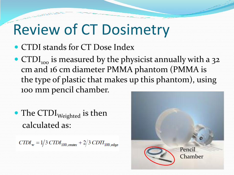
Review of CT Dosimetry CTDI stands for CT Dose Index
CTDI100 is measured by the physicist annually with a 32 cm and 16 cm diameter PMMA phantom (PMMA is the type of plastic that makes up this phantom), using 100 mm pencil chamber.
The CTDIWeighted is then
calculated as:
Pencil Chamber

Review of CT Dosimetry CTDIVolume is lastly calculated by dividing the
CTDIWeighted by the pitch.
Pitch is defined as the ratio of table travel per 360o
rotation (I) to the beam width (NxT)
Pitch of 0.5 results in doubling the CT dose
Pitch of 2.0 results in half the CT dose
Review of CT Dosimetry Q – What is the pitch if table increment (I) per 360
degree rotation is 60 mm and beam width (N x T) is 40 mm?
60 mm / 40 mm = 1.5
So the pitch is 1.5
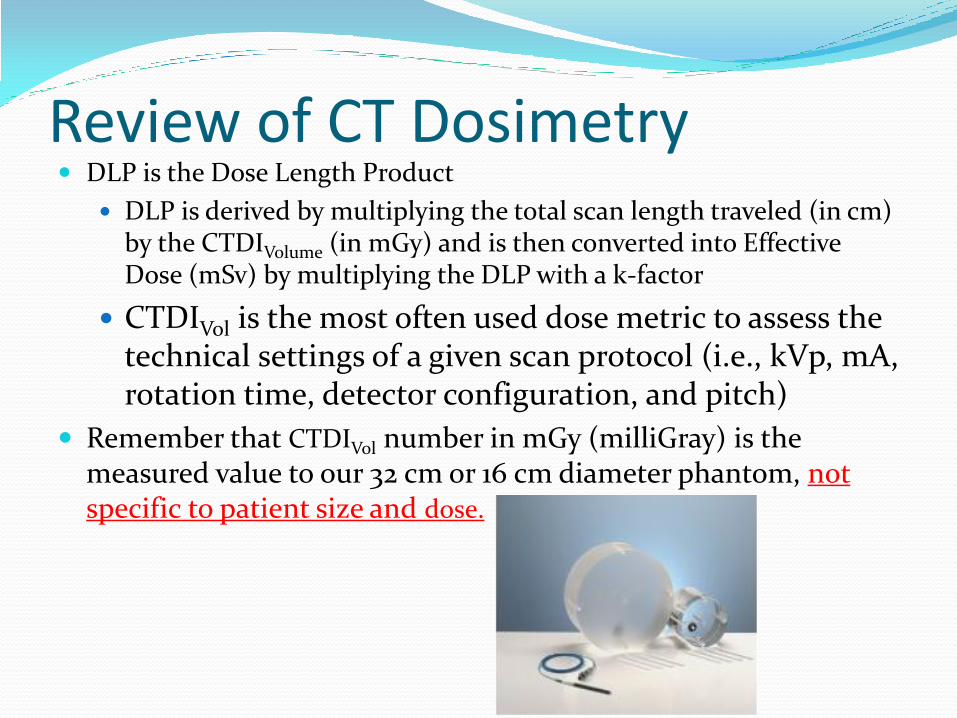
Review of CT Dosimetry DLP is the Dose Length Product
DLP is derived by multiplying the total scan length traveled (in cm) by the CTDIVolume (in mGy) and is then converted into Effective Dose (mSv) by multiplying the DLP with a k-factor
CTDIVol is the most often used dose metric to assess the technical settings of a given scan protocol (i.e., kVp, mA, rotation time, detector configuration, and pitch)
Remember that CTDIVol number in mGy (milliGray) is the measured value to our 32 cm or 16 cm diameter phantom, not specific to patient size and dose.
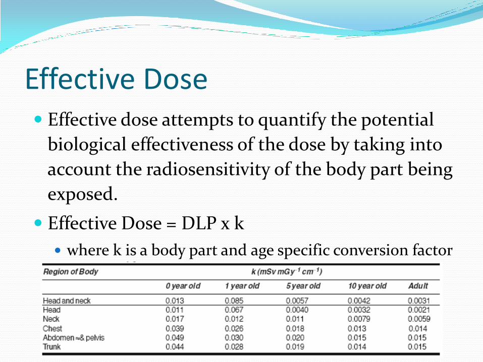
Effective Dose Effective dose attempts to quantify the potential
biological effectiveness of the dose by taking into
account the radiosensitivity of the body part being
exposed.
Effective Dose = DLP x k
where k is a body part and age specific conversion factor

Example of Effective Dose Calculation
Q: - What is the effective dose for an adult abdomen scan where the CTDIvol is 20 mGy and total length traveled by the x-ray path was 25 cm?
DLP = 20 mGy x 25 cm = 500 mGy-cm
k = 0.015 for Adult Abdomen (chart below)
Then, DLP x k = effective dose
A: - Effective Dose = 500 x 0.015 = 7.5 mSv
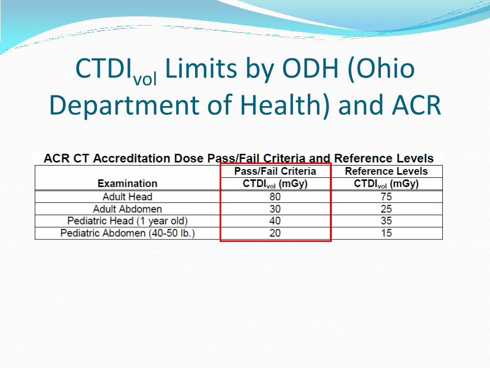
CTDIvol Limits by ODH (Ohio Department of Health) and ACR
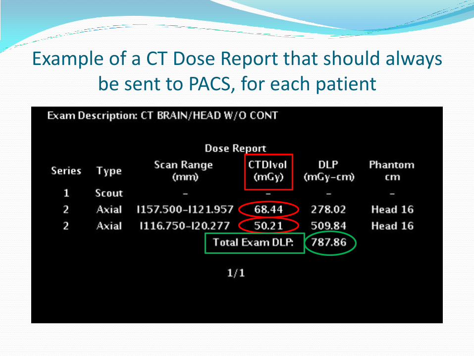
Example of a CT Dose Report that should always be sent to PACS, for each patient
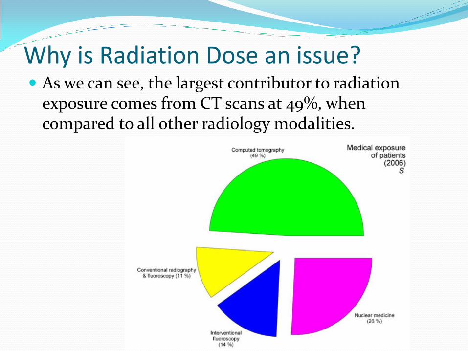
Why is Radiation Dose an issue? As we can see, the largest contributor to radiation
exposure comes from CT scans at 49%, when compared to all other radiology modalities.
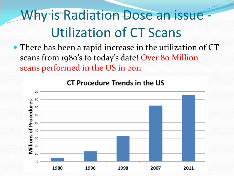
Why is Radiation Dose an issue - Utilization of CT Scans
There has been a rapid increase in the utilization of CT scans from 1980’s to today’s date! Over 80 Million scans performed in the US in 2011
Radiation Dose Optimization Concern issues with CT exposure
Abdominal CT is equivalent to 200 chest x-rays on a CT Scanner without Dose Reduction Technology
Many of our newer CT scanners have dose reduction technology (ASiR – Adaptive Statistical Iterative Reconstruction, we will see slides in more detail of this)
These technologies utilize reconstruction software, which allows for dose reduction on all types of scans performed
About a 20% dose reduction for Head CT
About a 30 to 40% dose reduction for Abdomen/Pelvis CT
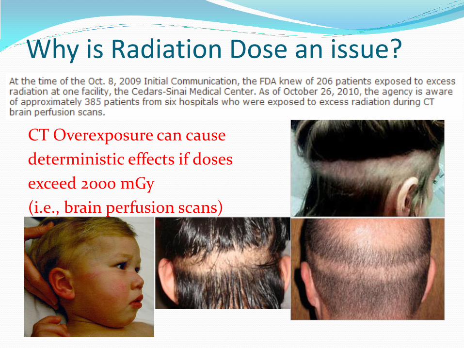
Why is Radiation Dose an issue?
CT Overexposure can cause
deterministic effects if doses
exceed 2000 mGy
(i.e., brain perfusion scans)
Why is Radiation Dose an issue? Most of our scanners, but not all, that have the XR-29
compliance package will also has Dose Check.
This dose check will indicate an alert value of a CTDIvol of greater than 1000 mGy (FDA Recommendation), which is half of the 2000 mGy dose level, where the onset of skin injury will happen.
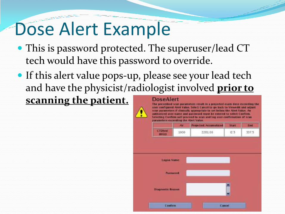
Dose Alert Example This is password protected. The superuser/lead CT
tech would have this password to override.
If this alert value pops-up, please see your lead tech and have the physicist/radiologist involved prior to scanning the patient.
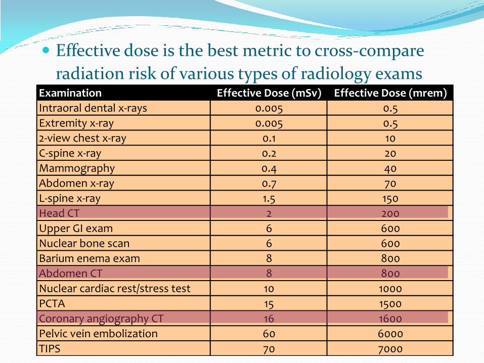
Effective dose is the best metric to cross-compare
radiation risk of various types of radiology exams
Examination Effective Dose (mSv) Effective Dose (mrem)
Intraoral dental x-rays 0.005 0.5
Extremity x-ray 0.005 0.5
2-view chest x-ray 0.1 10
C-spine x-ray 0.2 20
Mammography 0.4 40
Abdomen x-ray 0.7 70
L-spine x-ray 1.5 150
Head CT 2 200
Upper GI exam 6 600 *
Nuclear bone scan 6 600
Barium enema exam 8 800 *
Abdomen CT 8 800
Nuclear cardiac rest/stress test 10 1000
PCTA 15 1500 *
Coronary angiography CT 16 1600
Pelvic vein embolization 60 6000 *
TIPS 70 7000 *
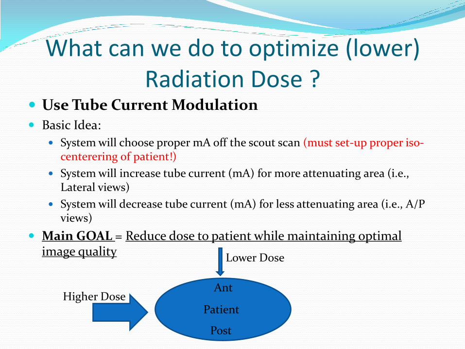
What can we do to optimize (lower) Radiation Dose ?
Use Tube Current Modulation Basic Idea:
System will choose proper mA off the scout scan (must set-up proper iso-centerering of patient!)
System will increase tube current (mA) for more attenuating area (i.e., Lateral views)
System will decrease tube current (mA) for less attenuating area (i.e., A/P views)
Main GOAL = Reduce dose to patient while maintaining optimal image quality
Higher Dose
Lower Dose
Patient
Post
Ant
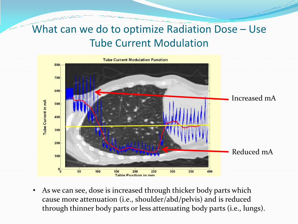
What can we do to optimize Radiation Dose – Use Tube Current Modulation
• As we can see, dose is increased through thicker body parts which cause more attenuation (i.e., shoulder/abd/pelvis) and is reduced through thinner body parts or less attenuating body parts (i.e., lungs).
Increased mA
Reduced mA
What can we do to optimize Radiation Dose – Use Tube Current Modulation
The operator has to select the correct protocol with the already built in Tube Current Modulation parameters
There are specific age/weight based protocols for pediatrics These protocols are set up by applications and/or lead techs with
the oversight of the radiologist/physicist, to ensure proper image quality and dose are within a tolerance range
Using the patient scout, the system computes the required mA to be utilized, based upon the selected Noise Index presets
Image quality parameters have different names by each vendor and are as follows: GE is Reference Noise Index Toshiba is Reference Standard Deviation Siemens is Quality Reference mAs Philips is Reference Image Acquisition
Ref: https://www.aapm.org/meetings/2011CTS/documents/McNitt-GrayTubeCurrentModulationv4.pdf
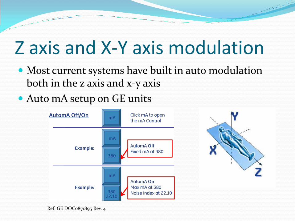
Z axis and X-Y axis modulation Most current systems have built in auto modulation
both in the z axis and x-y axis
Auto mA setup on GE units
Ref: GE DOC0871895 Rev. 4
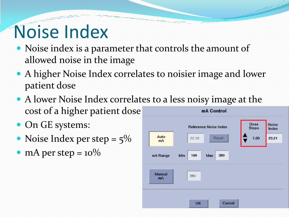
Noise Index Noise index is a parameter that controls the amount of
allowed noise in the image
A higher Noise Index correlates to noisier image and lower patient dose
A lower Noise Index correlates to a less noisy image at the cost of a higher patient dose
On GE systems:
Noise Index per step = 5%
mA per step = 10%
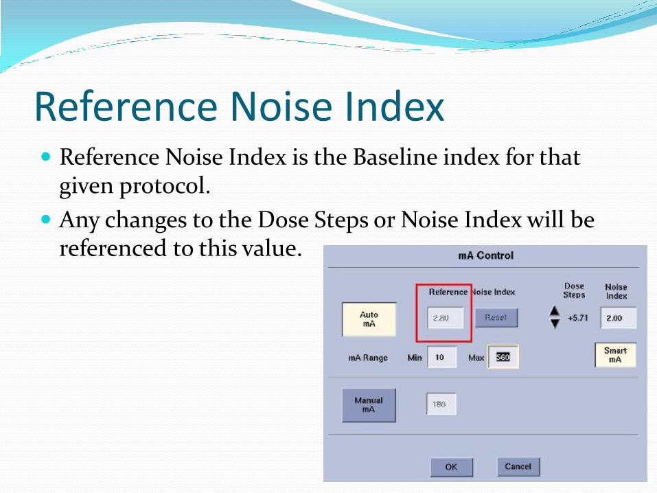
Reference Noise Index Reference Noise Index is the Baseline index for that
given protocol.
Any changes to the Dose Steps or Noise Index will be referenced to this value.
Auto mA *Auto mA will be disabled if there is no scout OR if the
patient orientation for the current series does not match the orientation of the scout
Summary:
Auto mA can modulate the mA along the Z-Axis
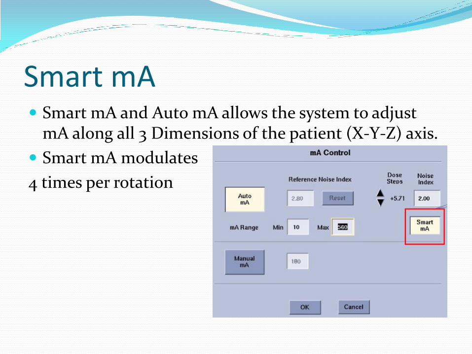
Smart mA Smart mA and Auto mA allows the system to adjust
mA along all 3 Dimensions of the patient (X-Y-Z) axis.
Smart mA modulates
4 times per rotation
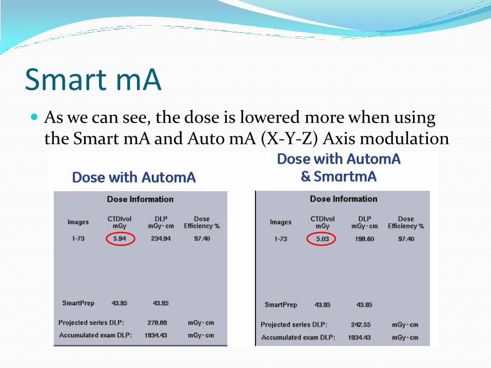
Smart mA As we can see, the dose is lowered more when using
the Smart mA and Auto mA (X-Y-Z) Axis modulation
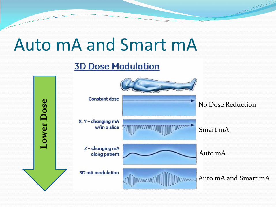
Auto mA and Smart mA
No Dose Reduction
Smart mA
Auto mA
Auto mA and Smart mA
L
ow
er
Do
se
Auto mA and Smart mA Summary
Smart mA adds modulation along the X-Y Axis to the Z axis modulation of Auto mA.
This modulation (Smart mA) lowers the dose even more as we have seen in the previous slide
The amount of noise that is acceptable is carried out by the Noise Index
Noise Index values should only be adjusted by the superuser/lead tech in conjunction with the radiologist/physicist.
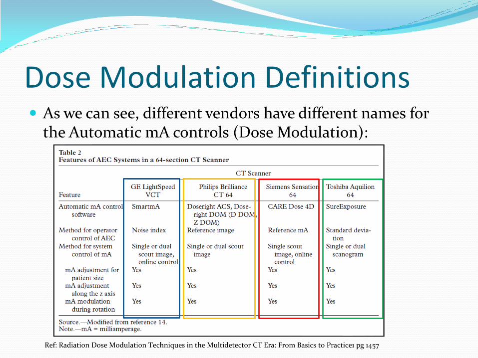
Dose Modulation Definitions As we can see, different vendors have different names for
the Automatic mA controls (Dose Modulation):
Ref: Radiation Dose Modulation Techniques in the Multidetector CT Era: From Basics to Practice1 pg 1457
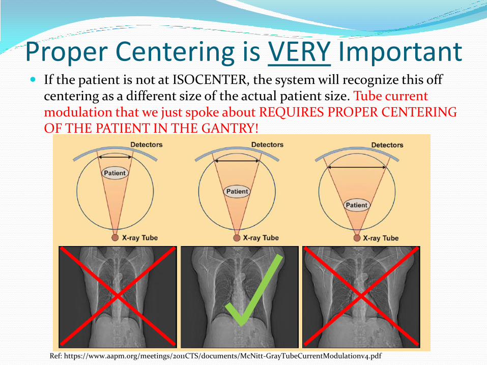
Proper Centering is VERY Important If the patient is not at ISOCENTER, the system will recognize this off
centering as a different size of the actual patient size. Tube current modulation that we just spoke about REQUIRES PROPER CENTERING OF THE PATIENT IN THE GANTRY!
Ref: https://www.aapm.org/meetings/2011CTS/documents/McNitt-GrayTubeCurrentModulationv4.pdf
ASiR ASiR is a reconstruction method that is a lot less
sensitive to Noise when compared to the traditional Filtered Back Projection processing
By reducing the mA, image quality will have higher noise
ASiR will then reconstruct these noisy images and make it a diagnostic quality image for proper/accurate clinical interpretation
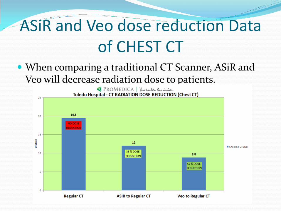
ASiR and Veo dose reduction Data of CHEST CT
When comparing a traditional CT Scanner, ASiR and Veo will decrease radiation dose to patients.
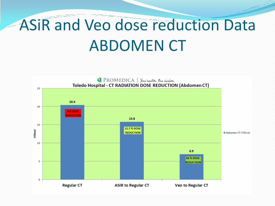
ASiR and Veo dose reduction Data ABDOMEN CT
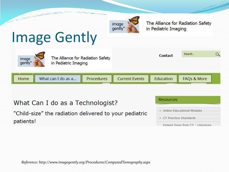
Image Gently
Reference: http://www.imagegently.org/Procedures/ComputedTomography.aspx
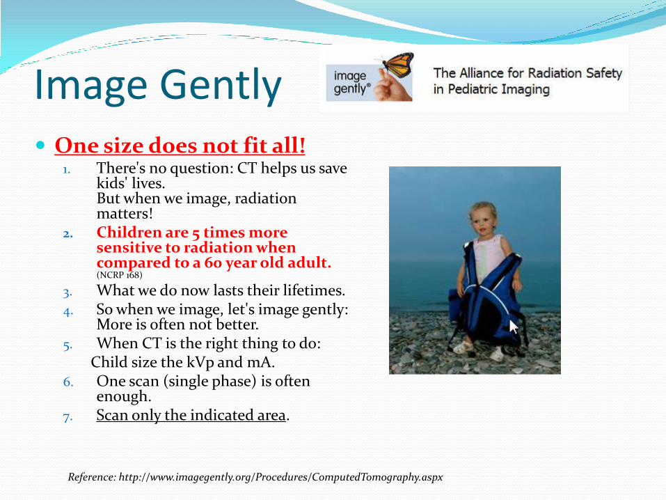
Image Gently One size does not fit all!
1. There's no question: CT helps us save kids' lives. But when we image, radiation matters!
2. Children are 5 times more sensitive to radiation when compared to a 60 year old adult. (NCRP 168)
3. What we do now lasts their lifetimes. 4. So when we image, let's image gently:
More is often not better. 5. When CT is the right thing to do: Child size the kVp and mA. 6. One scan (single phase) is often
enough. 7. Scan only the indicated area.
Reference: http://www.imagegently.org/Procedures/ComputedTomography.aspx

Image Wisely
Reference: http://www.imagewisely.org/Imaging-Modalities/Computed-Tomography/Imaging-Technologists#Topic0
If you have not done so yet, Please follow reference link below and take the pledge.
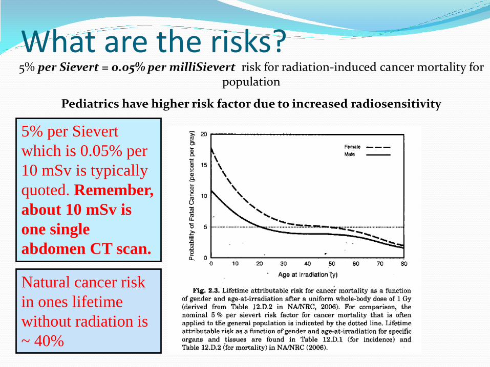
What are the risks? 5% per Sievert = 0.05% per milliSievert risk for radiation-induced cancer mortality for
population
Pediatrics have higher risk factor due to increased radiosensitivity
5% per Sievert
which is 0.05% per
10 mSv is typically
quoted. Remember,
about 10 mSv is
one single
abdomen CT scan.
Natural cancer risk
in ones lifetime
without radiation is
~ 40%
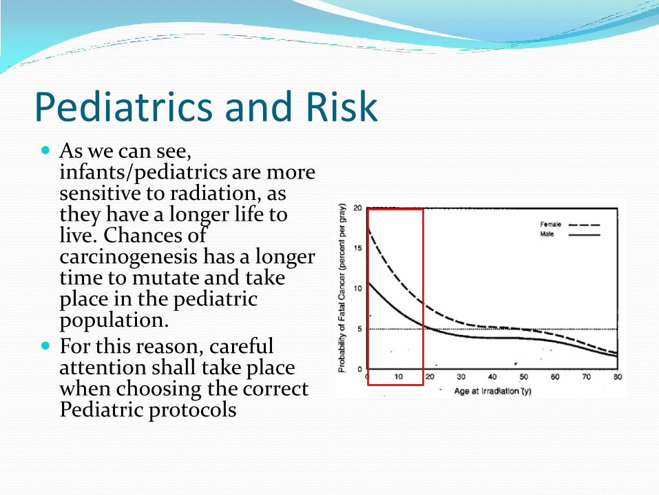
Pediatrics and Risk As we can see,
infants/pediatrics are more sensitive to radiation, as they have a longer life to live. Chances of carcinogenesis has a longer time to mutate and take place in the pediatric population.
For this reason, careful attention shall take place when choosing the correct Pediatric protocols
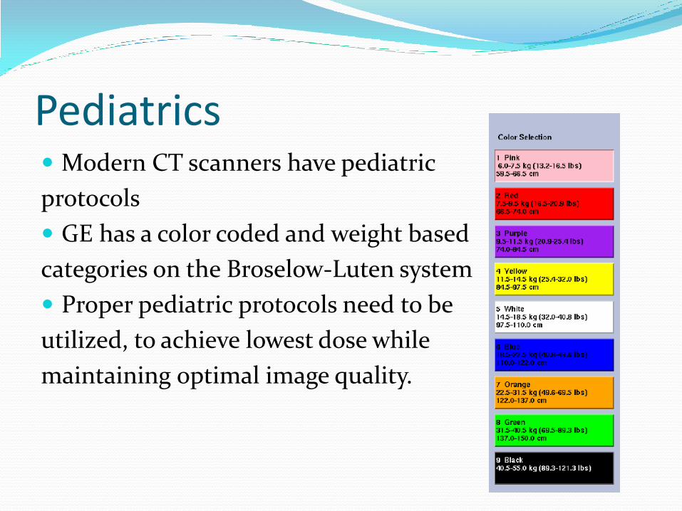
Pediatrics Modern CT scanners have pediatric
protocols
GE has a color coded and weight based
categories on the Broselow-Luten system
Proper pediatric protocols need to be
utilized, to achieve lowest dose while
maintaining optimal image quality.
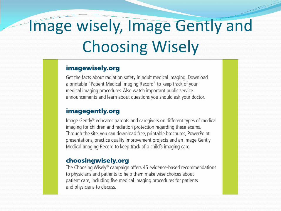
Image wisely, Image Gently and Choosing Wisely
Repeating CT Scans Due to Artifacts, Patient Motion etc.
Technologists’ should check with the interpreting physician (radiologist) if there is a concern about the possibility of repeating a CT scan (due to patient motion, artifacts, etc.)
This decision shall be made by the radiologist, as a repeat may not be necessary and warranted in some cases.
Pregnancy and Shielding 30% of all trauma patients are females in childbearing age (10-50 years old) Nearly 15% of female trauma victims may be pregnant at the time of injury Follow your current hospital policy on pregnancy screening
of all childbearing age patients. Shielding the patient over the fetus is recommended as long as it
does not interfere with the clinical region of interest If the lead shielding is in the primary x-ray beam, it will only
increase the dose by maxing out the mA modulation Careful placement of shield and scanning shall take place Most of the scatter radiation that the fetus receives is from internal
scatter. This internal scatter is therefore not shielded by the lead apron
Ref: http://www.aapm.org/meetings/amos2/pdf/59-17311-56148-931.pdfJ Trauma 29: 1628-1632, 1989
Pregnancy and CT Scans Fetus is most sensitive at 2 to 15 weeks post conception
Radiation at this time can cause smaller head size (microcephaly) and mental retardation
Gross congenital malformations
Based on risk data from human in-utero exposures, the
absolute risks of fetal effects are small at conceptus doses
of 100 mGy and negligible at doses of less than 50 mGy
Typical fetal dose when primary x-ray beam is over the fetus is typically less than 50 mGy
Pregnancy and Radiation How do we know this?
The historical data we use comes from
the Atomic bomb survivors irradiated
in utero from higher doses.
Hall EJ. Radiobiology for the Radiologist, LWW, 2000
Pregnancy and CT Scans Pregnancy Summary
Benefits of diagnostic imaging should be weighed as part of the risk assessment for pregnant patients
If the fetus is outside the primary x-ray beam, the radiation dose to the fetus would come from scatter only
This scatter radiation to the fetus is often considered negligible, but still not zero
If the fetus needs to be in the primary x-ray beam, precise analysis is required and optimal lowered techniques shall be used (consult with radiologist or physicist)
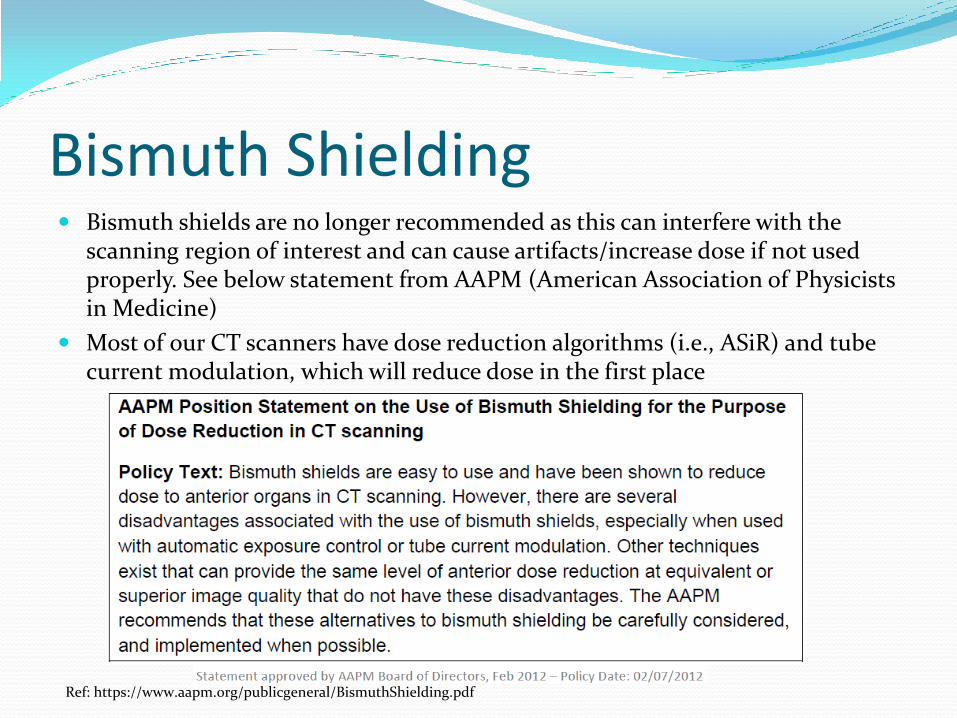
Bismuth Shielding Bismuth shields are no longer recommended as this can interfere with the
scanning region of interest and can cause artifacts/increase dose if not used properly. See below statement from AAPM (American Association of Physicists in Medicine)
Most of our CT scanners have dose reduction algorithms (i.e., ASiR) and tube current modulation, which will reduce dose in the first place
Ref: https://www.aapm.org/publicgeneral/BismuthShielding.pdf
Radiation Safety Officer
It is your responsibility to report to the Radiation Safety Officer (RSO) any unsafe conditions or radiation safety incidents
Additionally, any questions pertaining to radiation safety and regulatory compliance can be directed to the RSO
Radiation Safety Officer
Sven Gallo M.Sc.
Diagnostic Medical Physicist
Phone 419-291-4183
email: [email protected]