Embed Size (px)
Citation preview
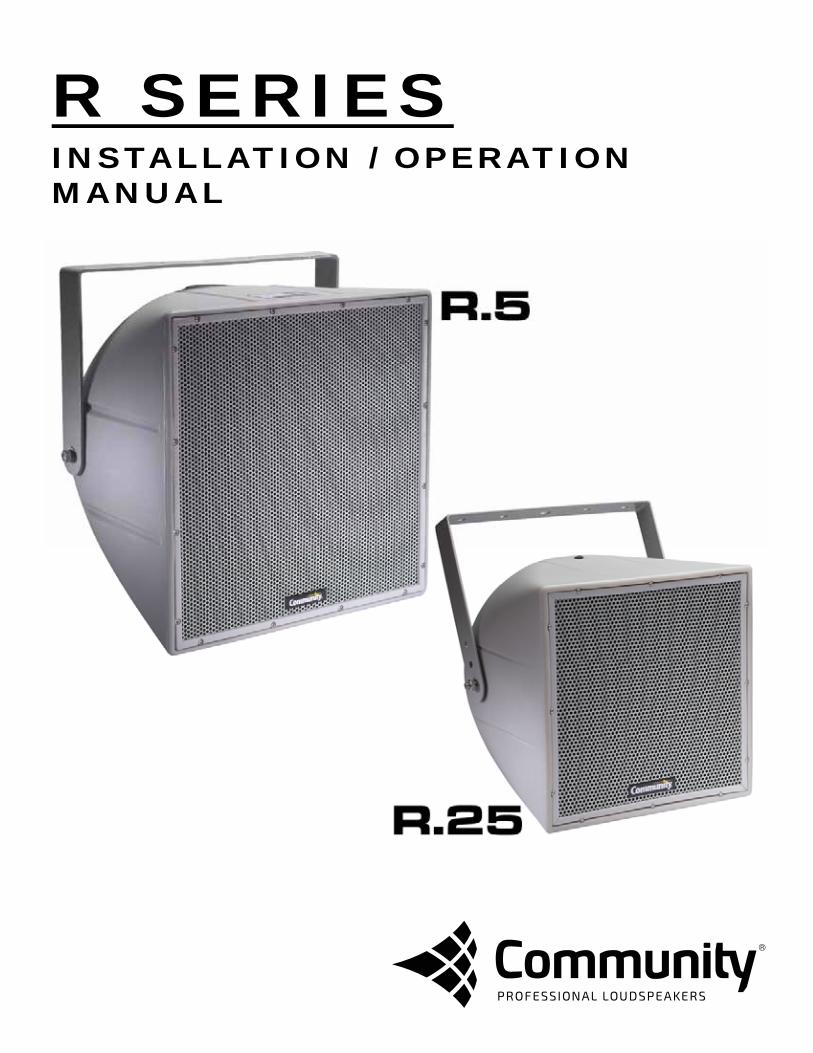
R SERIES INSTALLATION / OPERATION MANUAL
Community R SERIES Installation/Operation Manual for Models R.5 and R.25 — Page 2
EC STATEMENT OF CONFORMITY This document confirms that the range of products of Community Professional Loudspeakers bearing the CE label meets all of the requirements in the EMC directive 89/336/EEC laid down by the Member States Council for adjustment of legal requirements. Furthermore, the products comply with the rules and regulations referring to the electromagnetic compatibility of devices from 30-August-1995. The Community Professional Loudspeaker products bearing the CE label comply with the following harmonized or national standards: DIN EN 55013:08-1991 DIN EN 55020:05-1995 DIN EN 55082-1:03-1993 The authorized declaration and compatibility certification resides with the manufacturer and can be viewed upon request. The responsible manufacturer is the company: Community Light & Sound 333 East Fifth Street Chester, PA 19013 USA Phone: +1 610 876-3400 Fax: +1 610 874-0190 March 2015
EC STATEMENT OF CONFORMITY

Community R SERIES Installation/Operation Manual for Models R.5 and R.25 — Page 3
A TRADIT ION OF EXCELLENCE AND INNOVATION Since the founding of our company in 1968, Community has been a constant developer and innovator of loudspeaker technology. Many of our engineering achievements were undertaken to solve problems, when no prior solutions existed. Others resulted from simply seeing a better way to do things. Over the years our technologies have been imitated, and our methods have become common practice throughout the professional sound industry. However, developments like carbon fiber diaphragm compression drivers still stand alone, and well ahead of the competition. Just a few of Community’s unique accomplishments include the following:
First successful fiberglass mid, high frequency, and large-format bass horns. First compression loaded mid-range horn for touring systems - the LMF. First suspension-less diaphragm HF driver - the VHF100. First mid-range, full-decade (200 Hz - 2 kHz) high-power compression driver - the M4. First carbon fiber diaphragm compression drivers - M4, EM280, EM282. First Ferrofluid-cooled professional woofers - the VBS Loudspeakers. First product series with all drivers Ferrofluid-cooled. First air-cooled loudspeakers for touring systems - AirForce. First three-way cinema loudspeaker systems - Paramount Executive Studio Theatre, Warner Bros. screening theatre and dubbing rooms. First electro-acoustic system to equal the sound level of pneumatic warning sirens. First to provide loudspeaker coverage over an entire country - Denmark Emergency System. First comprehensive, calibrated data acquisition of sound reinforcement products. First integral signal-aligned three-way sound reinforcement systems - RS Loudspeakers. First pro audio company with an Internet Web site. First all horn-loaded, high-fidelity, weather-resistant loudspeaker - R2 Loudspeakers.
In line with our history of excellence and innovation, each Community product is manufactured in accordance with a complicated and exacting chain of procedures that ensure absolute quality. With our unique designs, our sophisticated techniques, and our proprietary materials and transducers, we are committed to bringing only the finest audio products to the many thousands of professional sound engineers, performers, and end users who rely on them daily.
Community Professional Loudspeakers 333 East Fifth Street, Chester, PA 19013-4511 USA Phone: +1 610 876-3400 Fax: +1 610 874-0190 www.communitypro.com © 2015 All Rights Reserved
WELCOME TO COMMUNITY
Community R SERIES Installation/Operation Manual for Models R.5 and R.25 — Page 4
CONTENTS
EC Statement of Conformity ........................................................................................................ Page 2
Welcome to Community ................................................................................................................ Page 3
Important Safety Information ....................................................................................................... Page 6
Rigging and Electrical Safety ...................................................................................................... Page 6
Unpacking and Inspection
Unpacking and Inspection ...................................................................................................... Page 7
Shipping Claims ...................................................................................................................... Page 7
What’s in the Box .................................................................................................................... Page 7
Quick Start
Features of the R.25 ............................................................................................................... Page 8
Features of the R.5 ................................................................................................................. Page 9
Electrical Installation and Safety ........................................................................................... Page 10
Mechanical Installation and Safety ....................................................................................... Page 11
Important Installation Notes .................................................................................................. Page 11
Introduction
Introduction ........................................................................................................................... Page 12
A Discussion of Weather-Resistance ................................................................................... Page 12
Description of the R SERIES ....................................................................................... Pages 12 - 13
R SERIES Features ..................................................................................................... Pages 14 - 15
R SERIES Models ........................................................................................................ Pages 16 - 17
R SERIES Accessories and Options .................................................................................... Page 17
Installation
Electrical Installation and Safety .................................................................................. Pages 18 - 21
Mechanical Installation and Safety .............................................................................. Pages 22 - 25
Important Installation Notes .................................................................................................. Page 26
System Optimization ................................................................................................................... Page 27
Specifications
R.25 Specifications ...................................................................................................... Pages 28 - 29
R.5COAX Specifications .............................................................................................. Pages 30 - 31
R.5HP Specifications ................................................................................................... Pages 32 - 33
R.5Z Specifications ...................................................................................................... Pages 34 - 35
R.5SUB Specifications ................................................................................................. Pages 36 - 37
Warranty and Service ......................................................................................................... Pages 38 - 39
TABLE OF CONTENTS
Community R SERIES Installation/Operation Manual for Models R.5 and R.25 — Page 5
TABLE OF FIGURES AND DRAWINGS
FIGURES AND DRAWINGS
Figure 1: Recommended Cable Gauge ............................................................................ Page 19
Figure 2: Protection Capacitor Equation ........................................................................... Page 20
Figure 3: 70-Volt Impedance Equation ............................................................................. Page 20
Figure 4: Mounting Point Detail......................................................................................... Page 22
Figure 5: Use of the Multi-Angle Aiming Strap .................................................................. Page 23
Figure 6: R.25 and R.5 Throw Distance Chart .................................................................. Page 24
Dimensional Drawings
R.25 and Mounting Bracket ..................................................................................... Page 29
R.5COAX and Mounting Bracket ............................................................................. Page 31
R.5HP and Mounting Bracket .................................................................................. Page 33
R.5Z and Mounting Bracket ..................................................................................... Page 35
R.5SUB and Mounting Bracket ................................................................................ Page 37
FIND THE LATEST ONLINE
Every effort has been made to ensure that the information contained in this manual was complete and accurate at the time of printing. However, due to ongoing technical advances, changes or modifications may have occurred that are not covered in this publication. The latest version of this manual and the most recent product information published by Communtiy is always available at http://www.communitypro.com. The publication date can be found on the rear cover or last page.
Community R SERIES Installation/Operation Manual for Models R.5 and R.25 — Page 6
IMPORTANT SAFETY INFORMATION Always follow these basic safety precautions when using or installing R SERIES loudspeakers and accessories:
Read these instructions. Keep these instructions. Heed all warnings.
Follow all instructions, particularly those pertaining to rigging, mounting, hanging and electrical connections. Only use accessories that are specified and approved by the manufacturer. The terms IMPORTANT, WARNING, and DANGER are used throughout this manual to alert the reader to important safety considerations. If you have any questions or do not understand the meaning of these terms, do not proceed with installation. Contact your local dealer, distributor, or call Community directly for assistance. These terms are defined below:
IMPORTANT: describes an operating condition or user action that may expose the equipment or user to potential damage or danger. WARNING: describes an operating condition or user action that will likely cause damage to the equipment or injury to the user or to others in the vicinity. DANGER: describes an operating condition or user action that will immediately damage the equipment and/or be extremely dangerous or life threatening to the user or to others in the vicinity.
RIGGING AND ELECTRICAL SAFETY
DANGER: The loudspeakers described in this manual are designed and intended to be ‘flown’ or suspended for maximum acoustical performance using a variety of rigging hardware, means, and methods. Installation of loudspeakers should only be performed by trained and qualified personnel. It is strongly recommended that a licensed and certified professional structural engineer approve the mounting design. Severe injury and/or loss of life may occur if these products are improperly installed. DANGER: R SERIES rigging fittings are rated at a Working Load Limit (WLL) of 100 lbs (45.4kg) with a 10:1 safety margin. No single rigging fitting should ever be subjected to a load that is greater than this stated limit. Failure to heed this warning could result in severe injury and/or loss of life. IMPORTANT: Refer to the sections on installation and connections later in this manual for additional information on rigging and electrical safety. IMPORTANT: The stainless steel mounting bolts that come installed in each enclosure must either be used to mount the Accessory Mounting Yoke or they must be kept in place to seal the enclosure from air leaks. If the rigging fittings do not remain sealed, air leaks will occur in the enclosure that will compromise the loudspeaker’s weather- resistance and its low frequency performance.
IMPORTANT SAFETY INFORMATION
Community R SERIES Installation/Operation Manual for Models R.5 and R.25 — Page 7
UNPACKING AND INSPECTION R SERIES loudspeakers are inherently rugged and are carefully packed in sturdy cartons. However, it’s wise to thoroughly inspect each unit after it has been removed from the packaging, as damage could occur during shipping.
SHIPPING CLAIMS Please note that once the shipment has left your dealer or the Community factory, the responsibility for damage is always borne by the freight company. If damage has occurred during shipping, you must file a claim directly with the freight company. It’s very important to contact the freight company as soon as possible after receiving your shipment, as most freight companies have a short time limit within which they will investigate claims. Make sure to save the carton and the packing material, as most claims will be denied if these materials are not retained. Your Community dealer and the factory will try to help in any way they can, but it is the responsibility of the party receiving the shipment to file the damage claim. It’s always a good idea to retain the carton and packing materials indefinitely, if possible, in the event that the unit may need to be returned to your dealer or distributor for repair in the future.
WHAT’S IN THE BOX Each shipping carton contains the following items: Loudspeaker System (Qty 1) Mounting Yoke – Preinstalled on Loudspeaker (Qty 1) Multi-Angle Aiming Strap - Only on R.5 Models (Qty 1) Operation Manual (Qty 1) Warranty Card (Qty 1)
UNPACKING AND INSPECTION
Community R SERIES Installation/Operation Manual for Models R.5 and R.25 — Page 8
NO. FEATURE DESCRIPTION
1 Mounting/Rigging Points
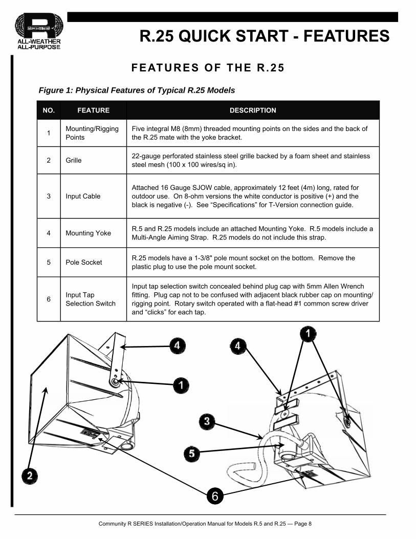
Five integral M8 (8mm) threaded mounting points on the sides and the back of the R.25 mate with the yoke bracket.
2 Grille 22-gauge perforated stainless steel grille backed by a foam sheet and stainless steel mesh (100 x 100 wires/sq in).
3 Input Cable Attached 16 Gauge SJOW cable, approximately 12 feet (4m) long, rated for outdoor use. On 8-ohm versions the white conductor is positive (+) and the black is negative (-). See “Specifications” for T-Version connection guide.
5 Pole Socket R.25 models have a 1-3/8" pole mount socket on the bottom. Remove the plastic plug to use the pole mount socket.
6 Input Tap Selection Switch
Input tap selection switch concealed behind plug cap with 5mm Allen Wrench fitting. Plug cap not to be confused with adjacent black rubber cap on mounting/rigging point. Rotary switch operated with a flat-head #1 common screw driver and “clicks” for each tap.
4 Mounting Yoke R.5 and R.25 models include an attached Mounting Yoke. R.5 models include a Multi-Angle Aiming Strap. R.25 models do not include this strap.
R.25 QUICK START - FEATURES
FEATURES OF THE R.25
Figure 1: Physical Features of Typical R.25 Models
6
Community R SERIES Installation/Operation Manual for Models R.5 and R.25 — Page 9
FEATURES OF THE R.5
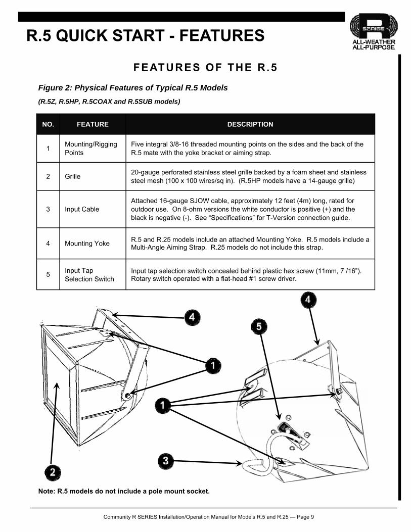
Figure 2: Physical Features of Typical R.5 Models
(R.5Z, R.5HP, R.5COAX and R.5SUB models)
NO. FEATURE DESCRIPTION
1 Mounting/Rigging Points
Five integral 3/8-16 threaded mounting points on the sides and the back of the R.5 mate with the yoke bracket or aiming strap.
2 Grille 20-gauge perforated stainless steel grille backed by a foam sheet and stainless steel mesh (100 x 100 wires/sq in). (R.5HP models have a 14-gauge grille)
3 Input Cable Attached 16-gauge SJOW cable, approximately 12 feet (4m) long, rated for outdoor use. On 8-ohm versions the white conductor is positive (+) and the black is negative (-). See “Specifications” for T-Version connection guide.
4 Mounting Yoke R.5 and R.25 models include an attached Mounting Yoke. R.5 models include a Multi-Angle Aiming Strap. R.25 models do not include this strap.
5 Input Tap Selection Switch
Input tap selection switch concealed behind plastic hex screw (11mm, 7 /16”). Rotary switch operated with a flat-head #1 screw driver.
R.5 QUICK START - FEATURES
Note: R.5 models do not include a pole mount socket.
Community R SERIES Installation/Operation Manual for Models R.5 and R.25 — Page 10
ELECTRICAL INSTALLATION AND SAFETY
Electrical Safety The output voltage and current capabilities of audio power amplifiers present a danger to installers especially in 70-volt and 100-volt distributed systems. To minimize the risk of electric shock from loudspeaker connecting cables, confirm that the power amplifiers are turned “off” before connecting loudspeaker cable to the loudspeaker or amplifier.
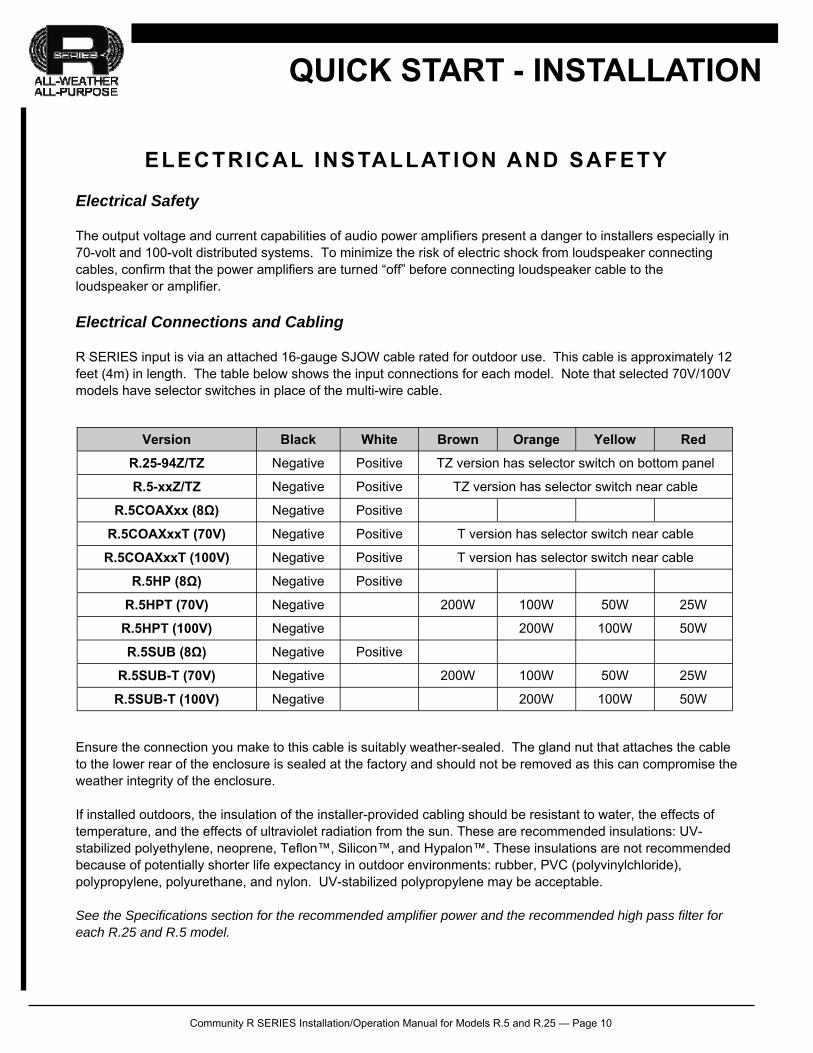
Electrical Connections and Cabling R SERIES input is via an attached 16-gauge SJOW cable rated for outdoor use. This cable is approximately 12 feet (4m) in length. The table below shows the input connections for each model. Note that selected 70V/100V models have selector switches in place of the multi-wire cable.
Ensure the connection you make to this cable is suitably weather-sealed. The gland nut that attaches the cable to the lower rear of the enclosure is sealed at the factory and should not be removed as this can compromise the weather integrity of the enclosure. If installed outdoors, the insulation of the installer-provided cabling should be resistant to water, the effects of temperature, and the effects of ultraviolet radiation from the sun. These are recommended insulations: UV-stabilized polyethylene, neoprene, Teflon™, Silicon™, and Hypalon™. These insulations are not recommended because of potentially shorter life expectancy in outdoor environments: rubber, PVC (polyvinylchloride), polypropylene, polyurethane, and nylon. UV-stabilized polypropylene may be acceptable. See the Specifications section for the recommended amplifier power and the recommended high pass filter for each R.25 and R.5 model.
QUICK START - INSTALLATION
Version Black White Brown Orange Yellow Red
R.25-94Z/TZ Negative Positive TZ version has selector switch on bottom panel
R.5-xxZ/TZ Negative Positive TZ version has selector switch near cable
R.5COAXxx (8Ω) Negative Positive
R.5COAXxxT (70V) Negative Positive T version has selector switch near cable
R.5COAXxxT (100V) Negative Positive
R.5HP (8Ω) Negative Positive
R.5HPT (70V) Negative 200W 100W 50W 25W
R.5HPT (100V) Negative 200W 100W 50W
R.5SUB (8Ω) Negative Positive
R.5SUB-T (70V) Negative 200W 100W 50W 25W
R.5SUB-T (100V) Negative 200W 100W 50W
T version has selector switch near cable
Community R SERIES Installation/Operation Manual for Models R.5 and R.25 — Page 11
QUICK START - INSTALLATION
MECHANICAL INSTALLATION AND SAFETY
Rigging Safety The loudspeakers described in this manual are designed and intended to be ‘flown’ or suspended for maximum acoustical performance using a variety of rigging hardware, means, and methods. It is essential that all installation work involving the suspension of these loudspeaker products be performed by competent, knowledgeable persons who understand safe rigging practices. Severe injury and/or loss of life may occur if these products are improperly installed.
Rigging / Mechanical Installation Five, integral threaded mounting points on the four sides and the back of the enclosure mate with the included yoke bracket or can be used for a custom fabricated mounting. As shipped, the unused holes have plugs that can be removed if these holes are needed for mounting or attaching the aiming strap. The plugs are purposely designed to "catch" on the mounting point threads and will be somewhat difficult to remove. Reinstall removed plugs into any unused holes, such as where the included yoke bracket was attached for shipment. The factory yoke attachment uses studs and a nut / lock washer / flat washer combination rather than bolts. This allows removal of the yoke to attach it to its supporting structure while leaving the studs on the enclosure. This procedure will make it easier to reinstall the R.5 or R.25 to the yoke without the need to both hold the loudspeaker and align bolts with the mounting points.
IMPORTANT INSTALLATION NOTES When tightening mounting hardware in the mounting points, do not use excessive force. The mounting point holes are approximately 7/16" (11 mm) deep. Any bolts used should not extend into the hole more than 3/8" (9.5 mm). If they do either you may not be able to tighten the bolt to the mounting or the threaded insert may dislodge in the effort to further tighten the bolt. Ensure that the hardware used to attach the included yoke or other mounting to the supporting structure and that the supporting structure itself are load rated for the intended use and suitably weather-resistant. We recommend angling the R.5 or R.25 loudspeaker at least 15 degrees downward so as to reduce the possibility of rain and other precipitation compromising the performance of the loudspeaker. In this orientation, the R.5, R.5HP and R.25 will maintain an EIEMA rating of IP55W, the R.5COAX and R.5SUB will maintain a rating of IP54W.
FOR MORE INFORMATION For more information on installing and operating your R SERIES loudspeaker, please refer to the “Installation and Connections” section of this manual or go to Community’s web site at www.communitypro.com. For applications support, service or warranty information, refer to Community’s web site or contact Community at 800-523-4934 or 610-876-3400.
Community R SERIES Installation/Operation Manual for Models R.5 and R.25 — Page 12
INTRODUCTION
Community’s R SERIES is a high-quality, high-fidelity product line designed to be highly weather-resistant. R SERIES products perform consistently in continuous outdoor exposure while simultaneously providing superlative acoustic performance.
This manual is intended to help you install and use R SERIES loudspeakers safely and effectively. It provides useful information to help you obtain the best performance, sound quality, and reliability from your R SERIES systems. We’ve provided a series of Quick-Start diagrams to enable you to install and operate the products immediately. However, we recommend that you read this manual in its entirety, to ensure that your R SERIES installation meets the highest possible standards.
While every attempt has been made to ensure this information is correct and up-to-date, Community continuously incorporates worthwhile improvements to each product which may include changes and/or modifications not contained in this manual.
A D ISCUSSION OF WEATHER-RESISTANCE
Weather-resistant is a relative term that describes a loudspeaker’s ability to resist the effects of weather in outdoor applications. Typical weather-related damage encountered in loudspeakers affects the enclosure, drivers, hardware, and internal components such as crossovers.
Community’s R SERIES enclosures are fabricated entirely of hand-laminated fiberglass, or roto-molded gray polyethylene, making them virtually impervious to weather-related effects. Fiberglass versions are coated with an attractive, light gray gel-coat to help keep the loudspeaker cooler in sunlight. High-frequency drivers and their diaphragms are made of highly weather-resistant materials. Midrange and low-frequency cones are treated to repel moisture. All external hardware on the loudspeaker is stainless steel. The perforated stainless steel grille has an open cell foam backing supplemented by a stainless steel mesh. This grille “sandwich” is acoustically transparent but highly resistant to moisture intrusion. The crossover is located within a sealed chamber that forms the enclosure for the low frequency drivers. There are no connectors on an R SERIES loudspeaker. Instead, a highly weather-resistant type SJOW cable is permanently attached to the loudspeaker through a weather-tight gland nut. This connection is far superior to any exposed connector.
DESCRIPTION OF THE R SERIES
All-Weather, All-Purpose
Though designed to handle the harshest environmental conditions, R SERIES is the perfect choice for many indoor environments. With 22 models to choose from, ranging from short throw with wide coverage angles to ultra-narrow, long throw systems, the task of designing an acoustically and economically effective sound system has never been easier. In many cases, a small number of R SERIES loudspeakers can provide top quality sound for a surprisingly large physical area, making them one of the most acoustically and economically effective solutions available anywhere. Visit www.communitypro.com to learn more about the entire R SERIES family including R6, R2, R1, R.5, R.25, R.35, R.15, RSH and RMG systems.
INTRODUCTION
Community R SERIES Installation/Operation Manual for Models R.5 and R.25 — Page 13
R SERIES Applications
R SERIES products are designed for permanent installation or portable use both outdoors and indoors. The primary applications for Community’s R SERIES are those where re-entrant horns, outdoor two-way horn/woofer loudspeakers, and some larger horn loudspeakers typically are used but lack capability for both high quality music reproduction and longer distance voice projection. By contrast, R SERIES products have excellent fidelity and wide frequency range for both music reproduction and voice projection.
R SERIES products are ideally suited for athletic fields (football, soccer, baseball, tennis) and field houses, theme parks, amusement parks, swimming pools, ski slopes, cruise ships, steeple carillons, fairgrounds, rodeos, small arenas, racing tracks, air shows, skating rinks, convention centers, factories, warehouses, and portable sound systems. They can complement Community W SERIES products for projects needing a combination of both longer and shorter-throw applications.
R.5 and R.25 Applications
R.5 and R.25 are designed for short- and medium-throw applications and for use in distributed systems. For example, R.5-94Z loudspeakers could be used on the parking lot or as under-balcony fill loudspeakers in a baseball stadium where R1 loudspeakers were the primary system. As another example, R.25 loudspeakers could be used in a distributed application in an outdoor waterpark or indoor swimming pool.
Choose the three-way, higher-output R.5HP for medium-throw, full-range applications such as covering the stands at a high-school football stadium. Add the R.5SUB to any R.5 or R.25 system to provide low-frequency support for music.
R SERIES and W SERIES –Complementary Product Lines
W SERIES is a major upgrade to Community’s second weather-resistant loudspeaker product line. W SERIES was designed for exceptional musicality and speech intelligibility using premium components housed in attractively molded fiberglass enclosures available in white or black.
Although the two lines overlap in application, Community’s R SERIES is primarily designed for medium- and long-throw, voice-range applications; whereas ,W SERIES loudspeakers are primarily designed for short- and medium-throw, musical applications. This provides the designer with many opportunities for systems using both product lines.
Thus, Community recommends R SERIES as the main loudspeaker systems for long-throw applications like sports stadiums and we recommend W SERIES for distributed systems in water parks or ski resorts that feature continuous music. We encourage designers to explore the highly effective end results that can readily be obtained by mixing and matching these two product categories to best suit the design requirements.
R SERIES Indoor and Portable Applications
R SERIES and W SERIES loudspeakers are great indoor loudspeakers. These loudspeakers are ideal for humidity-prone environments like gymnasiums and swimming areas. For portable use, the R.25 has a pole-mount socket on the bottom. To use the R.25 in a portable application, remove the plastic plug from this socket and install a suitable connector on the attached cable.
APPLICATIONS
Community R SERIES Installation/Operation Manual for Models R.5 and R.25 — Page 14
R SERIES FEATURES
R SERIES products are entirely constructed of corrosion-resistant materials like fiberglass, stainless steel, polyimide and carbon fiber, using sophisticated technologies to ensure they will withstand exposure to harsh environmental conditions.
Weather-Treated Cones
Community applies a special weather treatment to the low-frequency cones used in R SERIES products to maximize their long-term resistance to temperature, moisture and dry-rot problems.
Weather-Resistant High- and Mid-Frequency Diaphragms
R.25 and R.5 models feature non-metallic, weather-resistant diaphragms.
Ferrofluid
Most LF, MF & HF drivers use Ferrofluid in their voice coil gaps. Ferrofluid provides improved heat transfer to the magnet structure resulting in higher power handling, reduced distortion from fluidic dampening of mechanical resonance, and it seals the air gaps against corrosion and oxidation.
Driver Protection
Functioning as a multi-stage limiter, Community’s exclusive DYNA-TECH™ protection circuitry found in many R SERIES models provides precise and repeatable protection by reducing excessive power to the drivers. In other models PowerSense™ DDP (Dynamic Driver Protection) protection circuitry is built into the crossover to provide protection against excessive current.
Fiberglass or Polyethylene Horns and Enclosures
Horns and enclosures on larger R SERIES models are constructed of hand-laid fiberglass. Fiberglass is inherently weather-resistant while exhibiting the strength, stiffness and non-resonant characteristics needed to insure an acoustically inert loudspeaker enclosure. Enclosures and horns for most R.5 and R.25 models are attractively molded from highly weather-resistant polyethylene or high-impact ABS. The R.5HP horn is fiberglass.
The unique curved shape of R SERIES and WET II helps reduce standing waves within the enclosure for improved LF performance. Outdoors, the rounded shape inhibits standing water and helps to diffract wind, which in turn reduces the wind load on the supporting structure.
Horn Technology
Community is the originator and master of fiberglass horn manufacturing. The horns used in many WET II and R SERIES loudspeakers are constructed as one-piece, precision waveguides by hand-crafting on a precision mold using 100% hand-laminated fiberglass. Balsa wood is embedded and laminated into the fiberglass at strategic points to create extremely strong, double wall constructions which dampen vibrations providing clean, resonant-free sound. In compact R SERIES models, the horns are constructed of high-impact ABS plastic with reinforcing ribs to dampen vibrations. Perforations in the horn reduce reflections from the LF driver while still providing optimum pattern control and acoustic loading for the high frequency driver.
FEATURES
Community R SERIES Installation/Operation Manual for Models R.5 and R.25 — Page 15
Weather-Stop™ Grille
Each enclosure is fitted with Community’s proprietary Weather-Stop™ protective grille. The grille consists of a corrosion-resistant outer layer of perforated steel with a proprietary zinc-rich epoxy dual-layer powder coat finish in light grey, a center layer of UV-resistant reticulated foam, and an inner layer of fine-mesh screen made from a UV-resistant synthetic material that blocks rain and fights rusting. This grille assembly prevents water intrusion, while providing a high degree of acoustic transparency.
Stainless Steel Hardware
Exposed hardware and fasteners are made of corrosion-resistant stainless steel.
Input Cables
To help maintain its weather-resistant properties, there are no connectors on an R SERIES loudspeaker. Instead, input is via an attached cable rated for outdoor use.
Envirotech™ Technology
All internal circuitry is protected from the elements with our proprietary Envirotech coating which seals sensitive electronic components against the effects of moisture and corrosion.
High-Performance Crossovers and Autoformers
R.25 and R.5 models feature high-power, high-performance two-way and three-way passive crossover networks with over-current protection circuitry. 70V/100V models use a 200W, high-performance autoformer with lower loss than a true transformer (the R.5SUB-T uses a high-performance true transformer).
Versatile Mounting Accessories
Weather-resistant stainless steel yoke-style mounting brackets are included with most models, while a variety of optional mounting kits are available for others.
Custom Colors
For volume purchases, all R SERIES and W SERIES products may be ordered in custom color enclosures at a nominal fee to elegantly match their physical installation environment.
FEATURES
Community R SERIES Installation/Operation Manual for Models R.5 and R.25 — Page 16
R SERIES MODELS
The R SERIES family features 22 models that range in capability from short throw usage for local area fill (about 30 to 50 feet), to extremely long throw capable of reaching across an entire stadium (about 700 feet). A wide selection of coverage angles and power output capabilities characterize this versatile product line. A small, single 12” subwoofer (called the R.5SUB) and a much larger dual 12” subwoofer (called the R2SUB) are available to complement full-range systems. A full, horn-loaded subwoofer/bass augmentation loudspeaker is available as model R6-Basshorn. Smaller R SERIES products are injection molded ABS (R.15, R.35), rotationally molded of polyethylene (R.25, R.5), while the larger models are made from hand-laid fiberglass (R1, R2, R6). All models are available in architectural light grey, but custom colors are also available for volume purchases. All medium and long throw R SERIES systems feature horn loading in all frequency bands. The R2 is offered in three symmetric horn patterns and two asymmetric horn patterns, and all models except the R.5SUB, R6, R6-51, R.5HP, RMG and RSH are equipped with internal protection circuitry to guard against excessive power. Because of their versatility, performance and weather-resistant properties, R SERIES systems are found in many of the world’s preeminent motor speedways, sports venues, and convention centers.
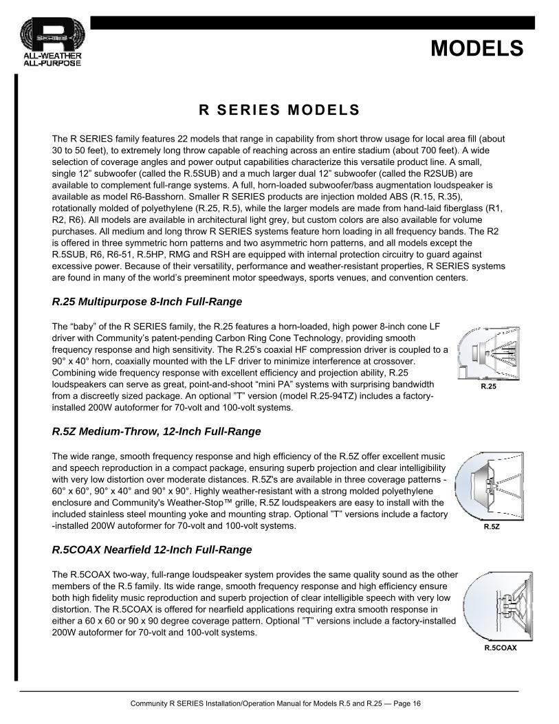
R.25 Multipurpose 8-Inch Full-Range
The “baby” of the R SERIES family, the R.25 features a horn-loaded, high power 8-inch cone LF driver with Community’s patent-pending Carbon Ring Cone Technology, providing smooth frequency response and high sensitivity. The R.25’s coaxial HF compression driver is coupled to a 90° x 40° horn, coaxially mounted with the LF driver to minimize interference at crossover. Combining wide frequency response with excellent efficiency and projection ability, R.25 loudspeakers can serve as great, point-and-shoot “mini PA” systems with surprising bandwidth from a discreetly sized package. An optional ”T” version (model R.25-94TZ) includes a factory-installed 200W autoformer for 70-volt and 100-volt systems.
R.5Z Medium-Throw, 12-Inch Full-Range
The wide range, smooth frequency response and high efficiency of the R.5Z offer excellent music and speech reproduction in a compact package, ensuring superb projection and clear intelligibility with very low distortion over moderate distances. R.5Z's are available in three coverage patterns - 60° x 60°, 90° x 40° and 90° x 90°. Highly weather-resistant with a strong molded polyethylene enclosure and Community's Weather-Stop™ grille, R.5Z loudspeakers are easy to install with the included stainless steel mounting yoke and mounting strap. Optional ”T” versions include a factory-installed 200W autoformer for 70-volt and 100-volt systems.
R.5COAX Nearfield 12-Inch Full-Range
The R.5COAX two-way, full-range loudspeaker system provides the same quality sound as the other members of the R.5 family. Its wide range, smooth frequency response and high efficiency ensure both high fidelity music reproduction and superb projection of clear intelligible speech with very low distortion. The R.5COAX is offered for nearfield applications requiring extra smooth response in either a 60 x 60 or 90 x 90 degree coverage pattern. Optional ”T” versions include a factory-installed 200W autoformer for 70-volt and 100-volt systems.
MODELS
R.25
R.5Z
R.5COAX
Community R SERIES Installation/Operation Manual for Models R.5 and R.25 — Page 17
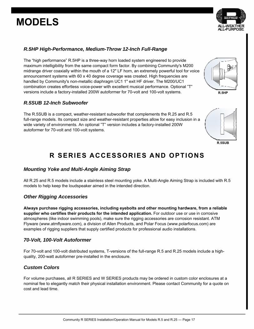
R.5HP High-Performance, Medium-Throw 12-Inch Full-Range
The “high performance” R.5HP is a three-way horn loaded system engineered to provide maximum intelligibility from the same compact form factor. By combining Community's M200 midrange driver coaxially within the mouth of a 12" LF horn, an extremely powerful tool for voice announcement systems with 60 x 40 degree coverage was created. High frequencies are handled by Community's non-metallic diaphragm UC1 1" exit HF driver. The M200/UC1 combination creates effortless voice-power with excellent musical performance. Optional ”T” versions include a factory-installed 200W autoformer for 70-volt and 100-volt systems.
R.5SUB 12-Inch Subwoofer
The R.5SUB is a compact, weather-resistant subwoofer that complements the R.25 and R.5 full-range models. Its compact size and weather-resistant properties allow for easy inclusion in a wide variety of environments. An optional ”T” version includes a factory-installed 200W autoformer for 70-volt and 100-volt systems.
R SERIES ACCESSORIES AND OPTIONS
Mounting Yoke and Multi-Angle Aiming Strap
All R.25 and R.5 models include a stainless steel mounting yoke. A Multi-Angle Aiming Strap is included with R.5 models to help keep the loudspeaker aimed in the intended direction.
Other Rigging Accessories
Always purchase rigging accessories, including eyebolts and other mounting hardware, from a reliable supplier who certifies their products for the intended application. For outdoor use or use in corrosive atmospheres (like indoor swimming pools), make sure the rigging accessories are corrosion resistant. ATM Flyware (www.atmflyware.com), a division of Allen Products, and Polar Focus (www.polarfocus.com) are examples of rigging suppliers that supply certified products for professional audio installations.
70-Volt, 100-Volt Autoformer
For 70-volt and 100-volt distributed systems, T-versions of the full-range R.5 and R.25 models include a high-quality, 200-watt autoformer pre-installed in the enclosure.
Custom Colors For volume purchases, all R SERIES and W SERIES products may be ordered in custom color enclosures at a nominal fee to elegantly match their physical installation environment. Please contact Community for a quote on cost and lead time.
MODELS
R.5HP
R.5SUB
Community R SERIES Installation/Operation Manual for Models R.5 and R.25 — Page 18
ELECTRICAL INSTALLATION AND SAFETY
DANGER: The output voltage and current of audio power amplifiers are a shock hazard especially in 70-volt and 100-volt distributed systems. To minimize the risk of electric shock from loudspeaker connecting cables, confirm that the power amplifiers are turned “off” before connecting loudspeaker cable to the loudspeaker or amplifier. Always follow local electrical codes and proper electrical safety procedures.
Inputs
R SERIES input is via an attached 16 Gauge SJOW cable rated for outdoor use. This cable is approximately 12 feet (4m) in length. The Specifications section shows the input connections for each model. Note that some 70V/100V models have selector switches in place of the multi-wire cable.
Ensure the connection you make to this cable is suitably weather-sealed. Do not remove the gland nut that attaches the cable to the lower rear of the loudspeaker as this can compromise the weather integrity of the enclosure.
Polarity
The white jacketed conductor is the positive or + signal wire and the black is the negative or – signal wire. Positive voltage applied to the + wire produces positive acoustic pressure at the mouth of the loudspeaker.
Impedance
R.5 and R.25 loudspeakers are rated at 8-ohms nominal impedance. The impedance of transformer versions (“T” suffix) depends on the tap chosen.
Recommended Amplifier Power
See the Specifications section in this manual for recommended amplifier power for each specific model. Using an amplifier of less power than recommended will not allow maximum performance of the system and can quickly damage the loudspeaker. The built-in DYNA-TECH protection circuitry (PowerSense DDP on model R1) cannot detect clipping nor will it detect when less than the recommended power is used. Correspondingly, using an amplifier of more power than recommended can result in overdriving the loudspeaker with the potential for damaging the drivers and/or the protection circuitry.
Recommended Cable Type and Size
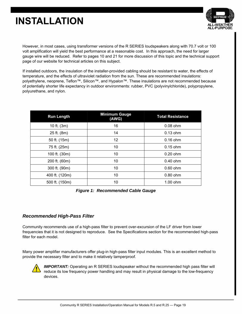
The resistance of the cable between the loudspeaker and the amplifier affects the performance of the loudspeaker. Cable with too high a resistance can cause power losses and impair low frequency performance by reducing the electrical damping factor. To minimize these problems it is desirable to keep the total cable resistance under 0.2 ohm. For lengths over 100 feet the wire gauges needed to meet this requirement are usually not practical to use for both physical and cost reasons. Therefore 10 Gauge is recommended as the most practical gauge for those situations. Use the following table to select the proper wire gauge. Either stranded or solid conductors are acceptable although cable with stranded conductors can be easier to work with. The run length for both conductors has been figured into the total resistance. Note the lower the gauge number the larger the wire size.
INSTALLATION
Community R SERIES Installation/Operation Manual for Models R.5 and R.25 — Page 19
However, in most cases, using transformer versions of the R SERIES loudspeakers along with 70.7 volt or 100 volt amplification will yield the best performance at a reasonable cost. In this approach, the need for larger gauge wire will be reduced. Refer to pages 10 and 21 for more discussion of this topic and the technical support page of our website for technical articles on this subject.
If installed outdoors, the insulation of the installer-provided cabling should be resistant to water, the effects of temperature, and the effects of ultraviolet radiation from the sun. These are recommended insulations: polyethylene, neoprene, Teflon™, Silicon™, and Hypalon™. These insulations are not recommended because of potentially shorter life expectancy in outdoor environments: rubber, PVC (polyvinylchloride), polypropylene, polyurethane, and nylon.
Recommended High-Pass Filter
Community recommends use of a high-pass filter to prevent over-excursion of the LF driver from lower frequencies that it is not designed to reproduce. See the Specifications section for the recommended high-pass filter for each model.
Many power amplifier manufacturers offer plug-in high-pass filter input modules. This is an excellent method to provide the necessary filter and to make it relatively tamperproof.
IMPORTANT: Operating an R SERIES loudspeaker without the recommended high pass filter will reduce its low frequency power handling and may result in physical damage to the low-frequency devices.
INSTALLATION
Run Length Minimum Gauge
(AWG) Total Resistance
10 ft. (3m) 16 0.08 ohm
25 ft. (8m) 14 0.13 ohm
50 ft. (15m) 12 0.16 ohm
75 ft. (25m) 10 0.15 ohm
100 ft. (30m) 10 0.20 ohm
200 ft. (60m) 10 0.40 ohm
300 ft. (90m) 10 0.60 ohm
400 ft. (120m) 10 0.80 ohm
500 ft. (150m) 10 1.00 ohm
Figure 1: Recommended Cable Gauge
Community R SERIES Installation/Operation Manual for Models R.5 and R.25 — Page 20
Use of Limiters
Community recommends use of a limiter to help prevent loudspeaker damage due to sudden transients (dropped microphones, etc.) or amplifier clipping. When used for this purpose, connect the limiter as the last item in the signal chain before the power amplifier (at the input to the power amplifier). Set the limiter’s “threshold” high enough so that no limiting occurs until the signal is in danger of clipping. Set the limiter’s “compression ratio” to a high enough ratio to prevent clipping. For professional audio equipment, a typical threshold setting would be +10 dBu and a typical compression ratio setting would be 10:1 or higher.
Use of Protection Capacitors
A properly chosen high-pass filter and limiter will provide all the protection needed for most systems. However, a properly chosen capacitor, inserted in the speaker line between the amplifier and loudspeaker, acts as an additional high-pass filter providing an additional level of protection when needed.
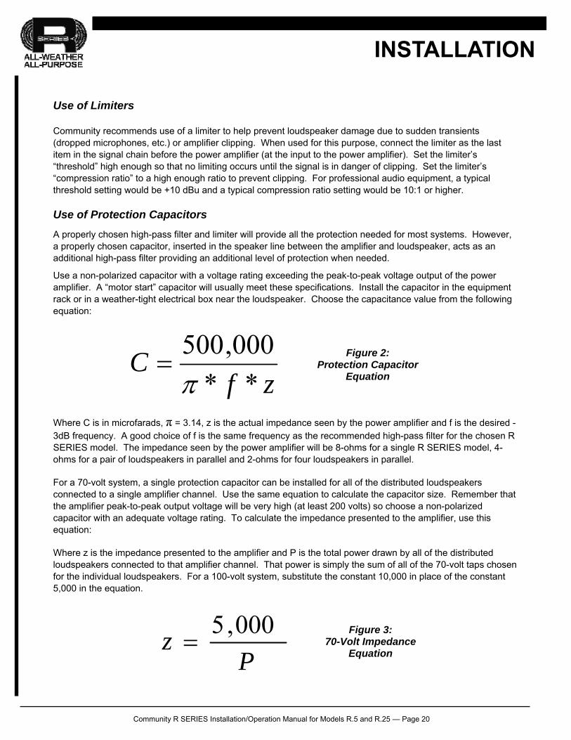
Use a non-polarized capacitor with a voltage rating exceeding the peak-to-peak voltage output of the power amplifier. A “motor start” capacitor will usually meet these specifications. Install the capacitor in the equipment rack or in a weather-tight electrical box near the loudspeaker. Choose the capacitance value from the following equation:
Where C is in microfarads, π = 3.14, z is the actual impedance seen by the power amplifier and f is the desired -3dB frequency. A good choice of f is the same frequency as the recommended high-pass filter for the chosen R SERIES model. The impedance seen by the power amplifier will be 8-ohms for a single R SERIES model, 4-ohms for a pair of loudspeakers in parallel and 2-ohms for four loudspeakers in parallel.
For a 70-volt system, a single protection capacitor can be installed for all of the distributed loudspeakers connected to a single amplifier channel. Use the same equation to calculate the capacitor size. Remember that the amplifier peak-to-peak output voltage will be very high (at least 200 volts) so choose a non-polarized capacitor with an adequate voltage rating. To calculate the impedance presented to the amplifier, use this equation:
Where z is the impedance presented to the amplifier and P is the total power drawn by all of the distributed loudspeakers connected to that amplifier channel. That power is simply the sum of all of the 70-volt taps chosen for the individual loudspeakers. For a 100-volt system, substitute the constant 10,000 in place of the constant 5,000 in the equation.
INSTALLATION
zfC
**
000,500
Figure 2:
Protection Capacitor Equation
Pz
000,5
Figure 3: 70-Volt Impedance
Equation
Community R SERIES Installation/Operation Manual for Models R.5 and R.25 — Page 21
Loudspeaker Grounding
In a low-impedance (8-ohm) system (not 70/100-volt), the minus (-) output terminal of the power amplifier is usually grounded. This provides a ground reference for the loudspeaker.
In a 70/100-volt system, it is necessary for the amplifier output terminals to be ungrounded. Thus, there is no ground reference for the loudspeaker. In most cases, this is acceptable. However, in outdoor installations in areas prone to lightning, it is possible for static electricity to build up on an ungrounded loudspeaker line. In an extreme case, the static electricity can reach a high enough voltage to arc to ground, either at the loudspeaker or at the power amplifier, causing damage to the loudspeaker or amplifier.
If this is a concern, it is possible to bleed static charge away from the loudspeaker line by connecting a resistor from each side of the line to ground either at the power amplifier or at the loudspeaker (in a weather-tight electrical box). Typically, a pair of 5,000-ohm resistors with 2-watt (or higher) ratings is used for this purpose for 70-volt lines. For 100-volt lines, use a pair of 10,000-ohm resistors.
Bi-amplification
R.5 and R.25 products include an internal passive crossover network. They are not designed for biamplification.
70-Volt, 100-Volt Autoformer
Transformer versions (“T” suffix) include an internal 200W, 70/100V autoformer or transformer. For 70V lines the input taps are 200W, 100W, 50W and 25W. For 100V lines the taps are 200W, 100W and 50W.
Some models have a multi-wire input cable to select the tap (R.5SUBT, R.5HPT). In this case, termination is usually best made inside an appropriate electrical box (weatherized as needed) using standard wire splicing methods. Other versions have a screwdriver-selectable switch accessible through a plug screw (R.5COAXxxT, R.25-94TZ & R.5xxTZ) which is accessed by removing the plug. Rotate the switch to the appropriate stop (“click”) for the desired tap using a flat-head #1 screwdriver.
Re-insert the plug screw after adjusting the tap to maintain weather-resistance. Use caution not to over tighten the plastic plug screw to avoid stripping the delicate plastic threads. For the R.25-94TZ, re-install the plug so that is flush with the exterior of the cabinet to avoid undue pressure on the switch mechanism. See the charts on pages 8-10 or the Specifications Section near the end of this manual for details about a specific model.
For additional information, Community’s web site includes a technical note on the design of 70-volt/100-volt distributed systems.
Connecting Multiple Loudspeakers to a Single Amplifier
The best way to connect multiple loudspeakers to a single power amplifier is to design a 70-volt or 100-volt distributed system. However, it is acceptable to connect as many as four 8-ohm loudspeakers in parallel and connect this combination to a single amplifier channel provided that amplifier is rated for the resulting 2-ohm impedance load.
INSTALLATION
Community R SERIES Installation/Operation Manual for Models R.5 and R.25 — Page 22
MECHANICAL INSTALLATION AND SAFETY
DANGER: The loudspeakers described in this manual are designed and intended to be ‘flown’ or suspended for maximum acoustical performance using a variety of rigging hardware, means, and methods. It is essential that all installation work involving the suspension of these loudspeaker products be performed by competent, knowledgeable persons who understand safe rigging practices. Severe injury and/or loss of life may occur if these products are improperly installed.
Important Notes on Rigging Loudspeakers
There are three areas of responsibility for rigging loudspeakers. The first is the building structure. Always consult with the building architect or structural engineer to assure the ability of the structure to support the loudspeaker system. The second area of responsibility is the loudspeaker itself. Community certifies its loudspeaker systems for suspension when they are properly installed according to our published guidelines. The third area of responsibility is everything between the loudspeaker and the building structure and the actual process of installation. The installing contractor assumes this responsibility. Loudspeaker rigging should be performed only by certified rigging professionals using certified rigging hardware chosen for the specific application. Prior to installation, the contractor should present a rigging plan, with drawing and detailed parts list, to a licensed structural engineer (P.E.) or architect for written approval.
Mounting Points
Five, integral threaded mounting points on the four sides and the back of the enclosure mate with the included yoke bracket or can be used for a custom fabricated mounting. As shipped, the unused holes have plugs that can be removed if these holes are needed for mounting or attaching the aiming strap. The plugs are purposely designed to "catch" on the mounting point threads and will be somewhat difficult to remove. Reinstall removed plugs into any unused holes, such as where the included yoke bracket was attached for shipment.
Acceptable Mounting Point Loading
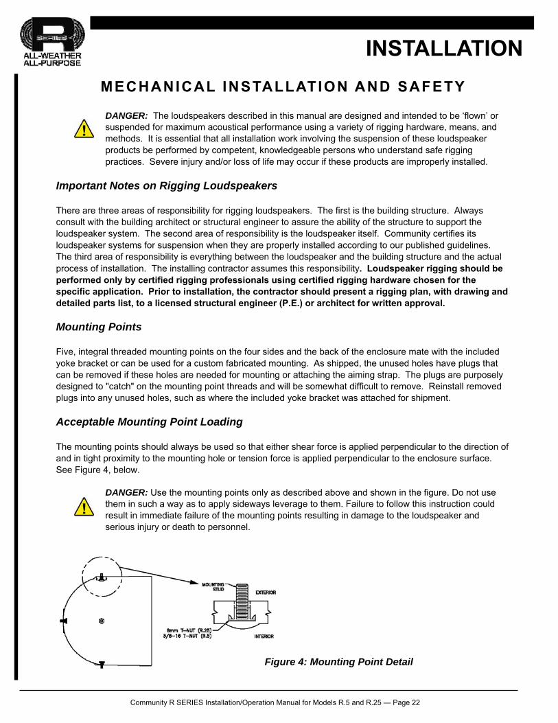
The mounting points should always be used so that either shear force is applied perpendicular to the direction of and in tight proximity to the mounting hole or tension force is applied perpendicular to the enclosure surface. See Figure 4, below.
DANGER: Use the mounting points only as described above and shown in the figure. Do not use them in such a way as to apply sideways leverage to them. Failure to follow this instruction could result in immediate failure of the mounting points resulting in damage to the loudspeaker and serious injury or death to personnel.
INSTALLATION
Figure 4: Mounting Point Detail
Community R SERIES Installation/Operation Manual for Models R.5 and R.25 — Page 23
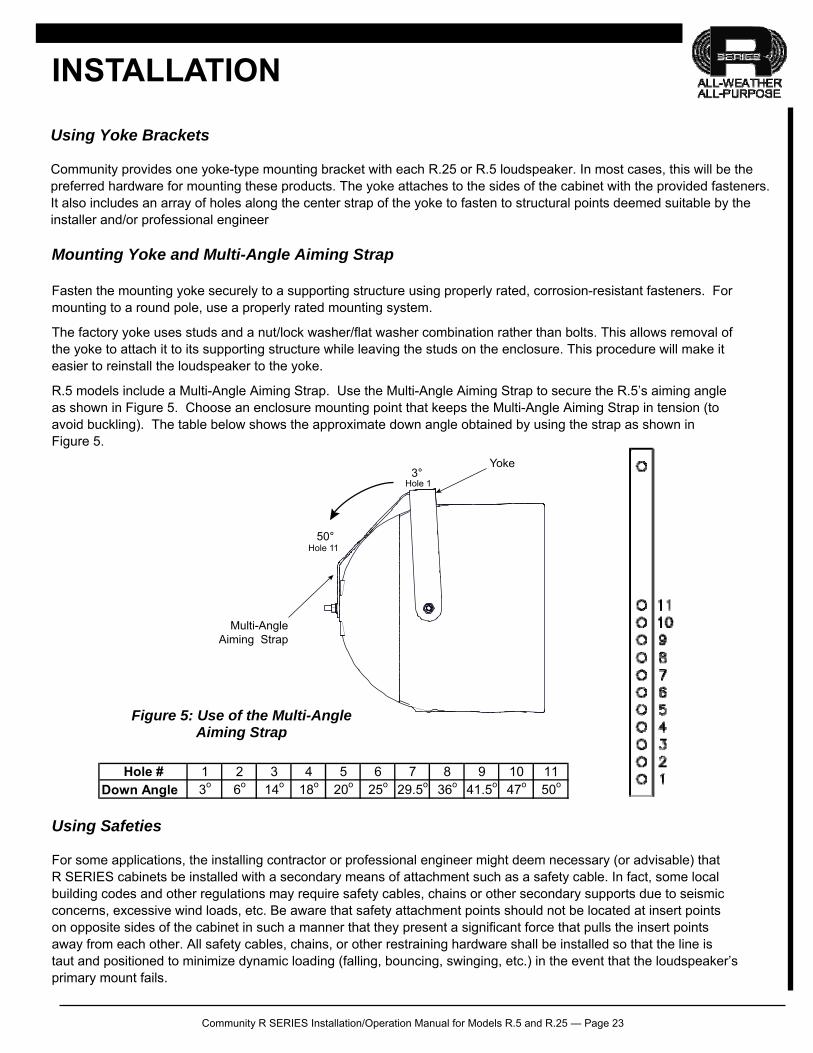
Mounting Yoke and Multi-Angle Aiming Strap
Fasten the mounting yoke securely to a supporting structure using properly rated, corrosion-resistant fasteners. For mounting to a round pole, use a properly rated mounting system.
The factory yoke uses studs and a nut/lock washer/flat washer combination rather than bolts. This allows removal of the yoke to attach it to its supporting structure while leaving the studs on the enclosure. This procedure will make it easier to reinstall the loudspeaker to the yoke.
R.5 models include a Multi-Angle Aiming Strap. Use the Multi-Angle Aiming Strap to secure the R.5’s aiming angle as shown in Figure 5. Choose an enclosure mounting point that keeps the Multi-Angle Aiming Strap in tension (to avoid buckling). The table below shows the approximate down angle obtained by using the strap as shown in Figure 5.
Using Safeties
For some applications, the installing contractor or professional engineer might deem necessary (or advisable) that R SERIES cabinets be installed with a secondary means of attachment such as a safety cable. In fact, some local building codes and other regulations may require safety cables, chains or other secondary supports due to seismic concerns, excessive wind loads, etc. Be aware that safety attachment points should not be located at insert points on opposite sides of the cabinet in such a manner that they present a significant force that pulls the insert points away from each other. All safety cables, chains, or other restraining hardware shall be installed so that the line is taut and positioned to minimize dynamic loading (falling, bouncing, swinging, etc.) in the event that the loudspeaker’s primary mount fails.
INSTALLATION
3°
50°
Hole 1
Hole 11
Yoke
Multi-Angle Aiming Strap
Figure 5: Use of the Multi-Angle Aiming Strap
Hole # 1 2 3 4 5 6 7 8 9 10 11Down Angle 3o 6o 14o 18o 20o 25o 29.5o 36o 41.5o 47o 50o
Using Yoke Brackets
Community provides one yoke-type mounting bracket with each R.25 or R.5 loudspeaker. In most cases, this will be the preferred hardware for mounting these products. The yoke attaches to the sides of the cabinet with the provided fasteners. It also includes an array of holes along the center strap of the yoke to fasten to structural points deemed suitable by the installer and/or professional engineer
Community R SERIES Installation/Operation Manual for Models R.5 and R.25 — Page 24
Community does offer in its catalog forged, rated eyebolts intended for rigging loudspeakers. However, these eyebolts are not rated for outdoor use and the shank is too long for the threaded inserts on R.25 and R.5 loudspeakers. Using an eyebolt with too long of a shank will not permit the eyebolt shoulder to properly seat against the exterior of the cabinet. Installers will need to procure appropriate hardware made from the appropriate material and shank length to meet the needs of each application.
In some cases, forged, overhead rated shoulder eyebolts may be used as attachment points on the cabinet for safety cables with some restrictions. The eyebolt must be screwed in and firmly seated (do not over tighten) with the shoulder of the eyebolt making contact with the rubber washer on the exterior of the cabinet. A rubber washer shall be used between the eyebolt and the cabinet to maintain weather resistance. Shims may be used between the eyebolt and the rubber washer to position the eye so that it is in the same plane as the suspension cable or chain. Care must be taken to ensure that the safety cable will not induce a load off-axis from the eyebolt’s threaded shank.
Hoist Rings provide a method of attachment which has advantages over eyebolts that permit more flexibility in regard to the pull/load direction of the safety line, though at a higher cost. Hoist rings include a hinged “eye” which allows the load applied to the cabinet threaded inserts to remain largely in shear, thus preserving the integrity of the insert point. The same precautions should be taken to properly seat the hoist ring as when seating an eye bolt.
As with all aspects of mounting and rigging loudspeakers, the use of eyebolts, hoist rings, and other safety cabling hardware should be included in a rigging plan approved by a professional engineer.
IMPORTANT: The mounting bolts that come installed in each R SERIES enclosure must either be used to mount the Accessory Mounting Yoke or they must remain in place. If the rigging fittings are not sealed, air leaks will occur in the enclosure that will compromise the loudspeaker’s weather-resistance and its low frequency performance.
IMPORTANT: Eyebolts and other mounting hardware for outdoor usage with R SERIES loudspeakers must be corrosion resistant steel properly rated for the load weight.
Custom Mounting Brackets
Custom brackets may be used. When mounting the loudspeaker the bracket should pull directly either in tension or shear on the mounting point (See Figure 5). It is recommended that any custom bracket be designed to utilize two mounting points on the opposite sides or top and bottom of the enclosure.
Orienting an R SERIES Loudspeaker
An R SERIES loudspeaker has a definite top, bottom and sides. However, a 180 degree inversion will not affect the coverage. When the top of the enclosure is up, the input cable gland nut will be down and to your right when looking directly at the front of the loudspeaker. Also, the manufacturer's label is on the top of the enclosure. Once the top is determined, you can properly orient the loudspeaker for your particular application according to the specified coverage pattern.
INSTALLATION
Community R SERIES Installation/Operation Manual for Models R.5 and R.25 — Page 25
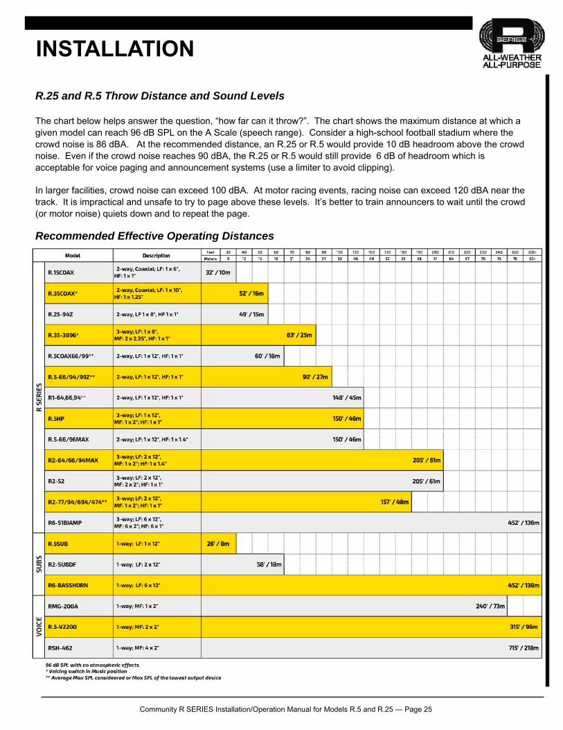
R.25 and R.5 Throw Distance and Sound Levels
The chart below helps answer the question, “how far can it throw?”. The chart shows the maximum distance at which a given model can reach 96 dB SPL on the A Scale (speech range). Consider a high-school football stadium where the crowd noise is 86 dBA. At the recommended distance, an R.25 or R.5 would provide 10 dB headroom above the crowd noise. Even if the crowd noise reaches 90 dBA, the R.25 or R.5 would still provide 6 dB of headroom which is acceptable for voice paging and announcement systems (use a limiter to avoid clipping).
In larger facilities, crowd noise can exceed 100 dBA. At motor racing events, racing noise can exceed 120 dBA near the track. It is impractical and unsafe to try to page above these levels. It’s better to train announcers to wait until the crowd (or motor noise) quiets down and to repeat the page.
Recommended Effective Operating Distances
INSTALLATION
Community R SERIES Installation/Operation Manual for Models R.5 and R.25 — Page 26
IMPORTANT INSTALLATION NOTES
Mounting Hardware Notes
When tightening mounting point hardware, do not use excessive force. Any bolts used in place of the supplied mounting studs should be properly rated stainless steel and should not extend into the hole more than 3/8" (9.5 mm). Ensure that the hardware used to attach the yoke (or other mounting hardware) to the supporting structure and that the supporting structure itself are load rated for the intended use and suitably weather resistant.
Notes on Weather-Resistance
No loudspeaker is completely “weather proof”. However, Community R SERIES loudspeakers are designed to withstand continuous outdoor exposure for many years of operation. Community R.5 loudspeakers have an IP (Ingress Protection) rating of IP55W in accordance with guidelines set forth under test standard IEC 60529 by the International Electrical Commission (IEC).
We recommend angling the R.5 or R.25 loudspeaker at least 5 degrees downward so as to reduce the possibility of rain and other precipitation compromising the performance of the loudspeaker. The R.5 or R.25 will maintain an IEC 60529 rating of IP55W in this orientation.
All five mounting holes must be sealed off with the stainless steel bolts, washers, and rubber washers supplied. If, for any reason, these bolts must be removed, seal off the hole with silicone caulking or some other suitable weather-tight sealant. The rubber washers supplied with the mounting bolts must always seat against the enclosure.
The gland nut securing the loudspeaker cable to the enclosure is sealed at the factory. Do not attempt to remove this nut or the weather-tight seal will be broken. If it is desired to replace the gland nut with a connector, the connector must be a weather-proof design. It must be suitably sealed to the enclosure with silicone caulk or some other suitable weather-tight sealant. The Neutrik model NLT4MP is an excellent connector for this purpose.
The grille assembly is designed to prevent normal and wind-driven rain from directly entering the mouth of the loudspeaker. The grille is not designed to withstand such things as being directly sprayed from a hose; therefore this should be avoided.
If you use any hardware in place of the stainless steel screws, bolts, nuts, and washers supplied, it should also be made of stainless steel. Community recommends periodic inspections of installed rigging hardware to discover and repair any unexpected corrosion or damage.
Always use outdoor-rated cable. Always seal connections in a weather-tight electrical box.
IMPORTANT: If the above instructions are not observed, the weather-resistant integrity of an R SERIES loudspeaker can be compromised. This can result in damage to or failure of the hardware or internal components.
F IELD SERVICE
Any driver or crossover service required is done from the front of the enclosure by removing the screws around the edge of the grille. For warranty repair, contact Community directly or ask us for the location of your nearest Authorized Service Center.
INSTALLATION

Community R SERIES Installation/Operation Manual for Models R.5 and R.25 — Page 27
SYSTEM OPTIMIZATION
CHOOSING THE RIGHT LOUDSPEAKERS AND ELECTRONICS
Choose R SERIES models with high enough maximum SPL to provide the needed SPL at the farthest listener with an appropriate headroom. Typical headroom factors are at least 6 dB for voice paging, at least 10 dB for voice reinforcement and at least 20 dB for music reinforcement. Choose R SERIES models with the right frequency response for the application. Subwoofers will improve the sound quality of a music reinforcement system but may reduce intelligibility in a voice-only system in a reverberant space. Choose R SERIES models with the right coverage patterns to cover the audience evenly. Point the loudspeakers at the listeners and away from walls and ceilings or outdoor obstructions. In outdoor applications, loudspeakers may be far enough apart to create artificial echoes in areas of overlapped coverage. Ideally, put all loudspeakers in a central location (central cluster design) or use a distributed system design to minimize this problem. In any case, minimize overlap when speakers are separated by more than approximately 40 feet. Choose power amplifiers large enough to provide the desired power output with enough headroom to avoid clipping. Use a limiter and high-pass filter to protect the loudspeakers. Follow proper wiring design and adjust gains and levels to minimize hum and noise.
COMMISSIONING THE SYSTEM Commissioning is the process of optimizing the performance of the system after it has been installed. There are several steps in commissioning including verifying the proper operation of each system component and adjusting system gains and levels. The last step in system commissioning is known as system equalization or “voicing”. Equalization is the process of adjusting the frequency response of the system to optimize voice intelligibility or musical sound quality (or both). Note that R SERIES loudspeakers are factory voiced to optimize their speech intelligibility and musical sound quality. For this reason, many designers find they can minimize overall system equalization and still achieve excellent voice intelligibility and musical sound quality.
Community R SERIES Installation/Operation Manual for Models R.5 and R.25 — Page 28
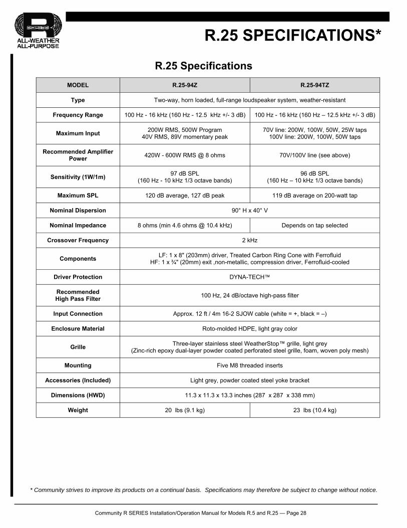
MODEL R.25-94Z R.25-94TZ
Type Two-way, horn loaded, full-range loudspeaker system, weather-resistant
Frequency Range 100 Hz - 16 kHz (160 Hz - 12.5 kHz +/- 3 dB) 100 Hz - 16 kHz (160 Hz – 12.5 kHz +/- 3 dB)
Maximum Input 200W RMS, 500W Program
40V RMS, 89V momentary peak 70V line: 200W, 100W, 50W, 25W taps
100V line: 200W, 100W, 50W taps
Recommended Amplifier Power
420W - 600W RMS @ 8 ohms 70V/100V line (see above)
Sensitivity (1W/1m) 97 dB SPL
(160 Hz - 10 kHz 1/3 octave bands) 96 dB SPL
(160 Hz – 10 kHz 1/3 octave bands)
Maximum SPL 120 dB average, 127 dB peak 119 dB average on 200-watt tap
Nominal Dispersion 90° H x 40° V
Nominal Impedance 8 ohms (min 4.6 ohms @ 10.4 kHz) Depends on tap selected
Crossover Frequency 2 kHz
Components LF: 1 x 8" (203mm) driver, Treated Carbon Ring Cone with Ferrofluid
HF: 1 x ¾" (20mm) exit ,non-metallic, compression driver, Ferrofluid-cooled
Driver Protection DYNA-TECH™
Recommended High Pass Filter
100 Hz, 24 dB/octave high-pass filter
Input Connection Approx. 12 ft / 4m 16-2 SJOW cable (white = +, black = –)
Enclosure Material Roto-molded HDPE, light gray color
Grille Three-layer stainless steel WeatherStop™ grille, light grey
(Zinc-rich epoxy dual-layer powder coated perforated steel grille, foam, woven poly mesh)
Mounting Five M8 threaded inserts
Accessories (Included) Light grey, powder coated steel yoke bracket
Dimensions (HWD)
Weight 20 lbs (9.1 kg) 23 lbs (10.4 kg)
11.3 x 11.3 x 13.3 inches (287 x 287 x 338 mm)
R.25 SPECIFICATIONS*
R.25 Specifications
* Community strives to improve its products on a continual basis. Specifications may therefore be subject to change without notice.
Community R SERIES Installation/Operation Manual for Models R.5 and R.25 — Page 29
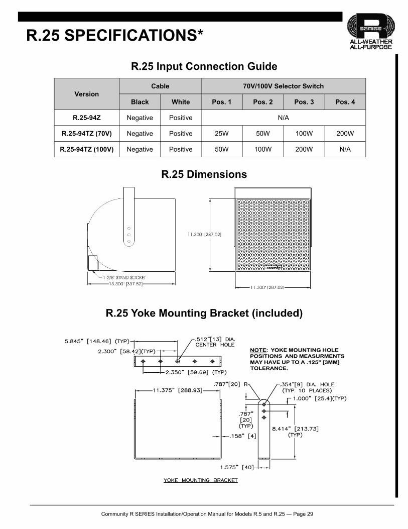
R.25 Dimensions
Cable 70V/100V Selector Switch
Black White Pos. 1 Pos. 2 Pos. 3 Pos. 4
R.25-94Z Negative Positive N/A
R.25-94TZ (70V) Negative Positive 25W 50W 100W 200W
R.25-94TZ (100V) Negative Positive 50W 100W 200W N/A
Version
R.25 Input Connection Guide
R.25 Yoke Mounting Bracket (included)
R.25 SPECIFICATIONS*
Community R SERIES Installation/Operation Manual for Models R.5 and R.25 — Page 30
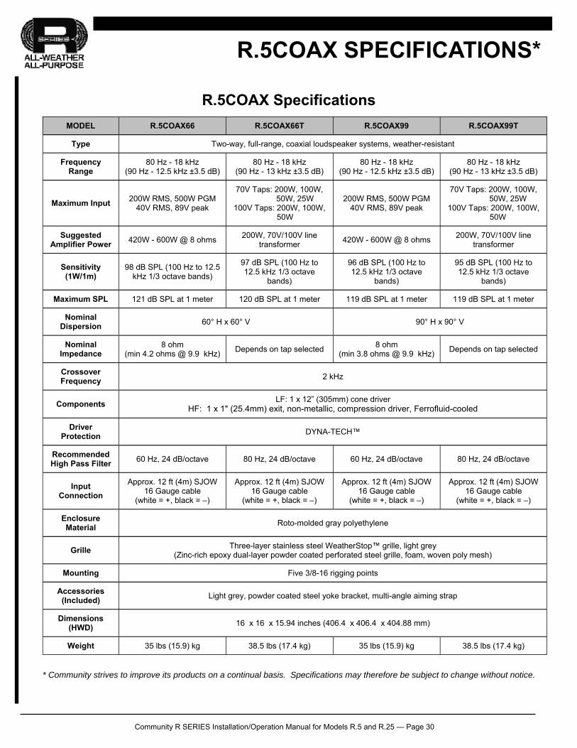
MODEL R.5COAX66 R.5COAX66T R.5COAX99 R.5COAX99T
Type Two-way, full-range, coaxial loudspeaker systems, weather-resistant
Frequency Range
80 Hz - 18 kHz (90 Hz - 12.5 kHz ±3.5 dB)
80 Hz - 18 kHz (90 Hz - 13 kHz ±3.5 dB)
80 Hz - 18 kHz (90 Hz - 12.5 kHz ±3.5 dB)
80 Hz - 18 kHz (90 Hz - 13 kHz ±3.5 dB)
Maximum Input 200W RMS, 500W PGM
40V RMS, 89V peak
70V Taps: 200W, 100W, 50W, 25W
100V Taps: 200W, 100W, 50W
200W RMS, 500W PGM 40V RMS, 89V peak
70V Taps: 200W, 100W, 50W, 25W
100V Taps: 200W, 100W, 50W
Suggested Amplifier Power
420W - 600W @ 8 ohms 200W, 70V/100V line
transformer 420W - 600W @ 8 ohms
200W, 70V/100V line transformer
Sensitivity (1W/1m)
98 dB SPL (100 Hz to 12.5 kHz 1/3 octave bands)
97 dB SPL (100 Hz to 12.5 kHz 1/3 octave
bands)
96 dB SPL (100 Hz to 12.5 kHz 1/3 octave
bands)
95 dB SPL (100 Hz to 12.5 kHz 1/3 octave
bands)
Maximum SPL 121 dB SPL at 1 meter 120 dB SPL at 1 meter 119 dB SPL at 1 meter 119 dB SPL at 1 meter
Nominal Dispersion
60° H x 60° V 90° H x 90° V
Nominal Impedance
8 ohm (min 4.2 ohms @ 9.9 kHz)
Depends on tap selected 8 ohm
(min 3.8 ohms @ 9.9 kHz) Depends on tap selected
Crossover Frequency
2 kHz
Components
Driver Protection
DYNA-TECH™
Recommended High Pass Filter
60 Hz, 24 dB/octave 80 Hz, 24 dB/octave 60 Hz, 24 dB/octave 80 Hz, 24 dB/octave
Input Connection
Approx. 12 ft (4m) SJOW 16 Gauge cable
(white = +, black = –)
Approx. 12 ft (4m) SJOW 16 Gauge cable
(white = +, black = –)
Approx. 12 ft (4m) SJOW 16 Gauge cable
(white = +, black = –)
Approx. 12 ft (4m) SJOW 16 Gauge cable
(white = +, black = –)
Enclosure Material
Roto-molded gray polyethylene
Grille Three-layer stainless steel WeatherStop™ grille, light grey
(Zinc-rich epoxy dual-layer powder coated perforated steel grille, foam, woven poly mesh)
Mounting Five 3/8-16 rigging points
Accessories (Included)
Light grey, powder coated steel yoke bracket, multi-angle aiming strap
Dimensions (HWD)
16 x 16 x 15.94 inches (406.4 x 406.4 x 404.88 mm)
Weight 35 lbs (15.9) kg 38.5 lbs (17.4 kg) 35 lbs (15.9) kg 38.5 lbs (17.4 kg)
LF: 1 x 12” (305mm) cone driver HF: 1 x 1" (25.4mm) exit, non-metallic, compression driver, Ferrofluid-cooled
R.5COAX SPECIFICATIONS*
* Community strives to improve its products on a continual basis. Specifications may therefore be subject to change without notice.
R.5COAX Specifications
Community R SERIES Installation/Operation Manual for Models R.5 and R.25 — Page 31
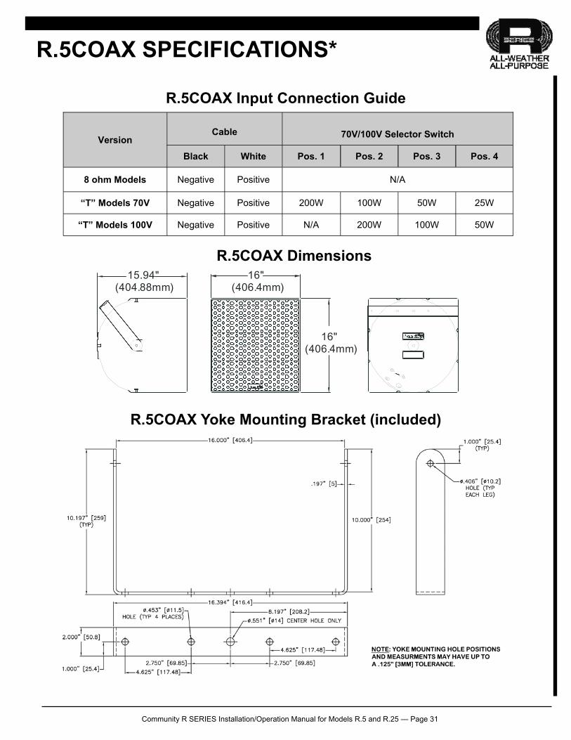
Cable
70V/100V Selector Switch
Black White Pos. 1 Pos. 2 Pos. 3 Pos. 4
8 ohm Models Negative Positive N/A
“T” Models 70V Negative Positive 200W 100W 50W 25W
“T” Models 100V Negative Positive N/A 200W 100W 50W
Version
R.5COAX Input Connection Guide
16"(406.4mm)
16"(406.4mm)
15.94"(404.88mm)
R.5COAX Dimensions
R.5COAX SPECIFICATIONS*
R.5COAX Yoke Mounting Bracket (included)
Community R SERIES Installation/Operation Manual for Models R.5 and R.25 — Page 32
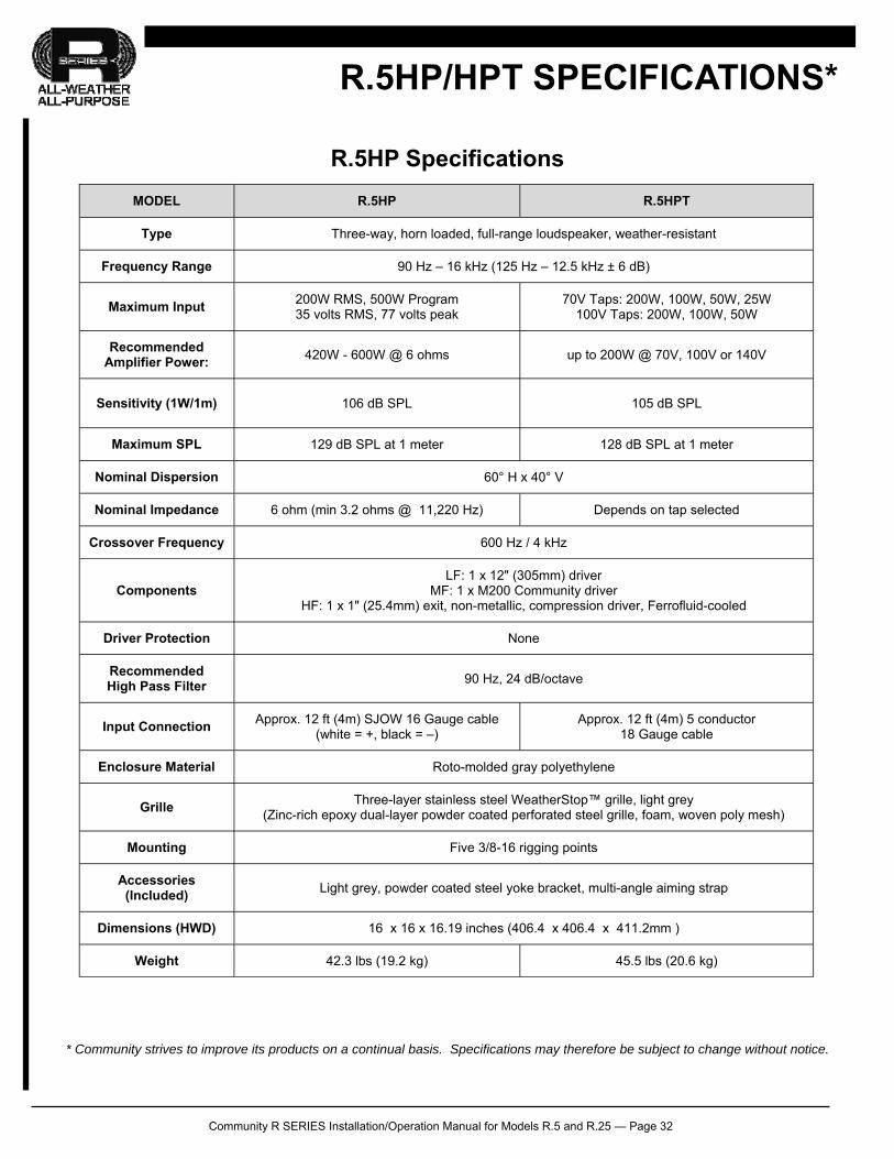
MODEL R.5HP R.5HPT
Type Three-way, horn loaded, full-range loudspeaker, weather-resistant
Frequency Range 90 Hz – 16 kHz (125 Hz – 12.5 kHz ± 6 dB)
Maximum Input 200W RMS, 500W Program 35 volts RMS, 77 volts peak
70V Taps: 200W, 100W, 50W, 25W 100V Taps: 200W, 100W, 50W
Recommended Amplifier Power:
420W - 600W @ 6 ohms up to 200W @ 70V, 100V or 140V
Sensitivity (1W/1m) 106 dB SPL 105 dB SPL
Maximum SPL 129 dB SPL at 1 meter 128 dB SPL at 1 meter
Nominal Dispersion
Nominal Impedance 6 ohm (min 3.2 ohms @ 11,220 Hz) Depends on tap selected
Crossover Frequency 600 Hz / 4 kHz
Components LF: 1 x 12" (305mm) driver
MF: 1 x M200 Community driver HF: 1 x 1" (25.4mm) exit, non-metallic, compression driver, Ferrofluid-cooled
Driver Protection None
Recommended High Pass Filter
90 Hz, 24 dB/octave
Input Connection Approx. 12 ft (4m) SJOW 16 Gauge cable
(white = +, black = –) Approx. 12 ft (4m) 5 conductor
18 Gauge cable
Enclosure Material Roto-molded gray polyethylene
Grille Three-layer stainless steel WeatherStop™ grille, light grey
(Zinc-rich epoxy dual-layer powder coated perforated steel grille, foam, woven poly mesh)
Mounting Five 3/8-16 rigging points
Accessories (Included)
Light grey, powder coated steel yoke bracket, multi-angle aiming strap
Dimensions (HWD) 16 x 16 x 16.19 inches (406.4 x 406.4 x 411.2mm )
Weight 42.3 lbs (19.2 kg) 45.5 lbs (20.6 kg)
60° H x 40° V
R.5HP/HPT SPECIFICATIONS*
R.5HP Specifications
* Community strives to improve its products on a continual basis. Specifications may therefore be subject to change without notice.
Community R SERIES Installation/Operation Manual for Models R.5 and R.25 — Page 33
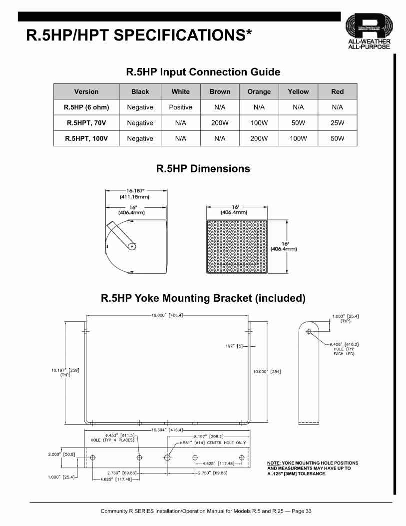
Version Black White Brown Orange Yellow Red
R.5HP (6 ohm) Negative Positive N/A N/A N/A N/A
R.5HPT, 70V Negative N/A 200W 100W 50W 25W
R.5HPT, 100V Negative N/A N/A 200W 100W 50W
R.5HP/HPT SPECIFICATIONS*
R.5HP Input Connection Guide
R.5HP Dimensions
R.5HP Yoke Mounting Bracket (included)
Community R SERIES Installation/Operation Manual for Models R.5 and R.25 — Page 34
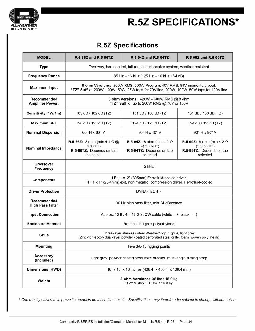
MODEL R.5-66Z and R.5-66TZ R.5-94Z and R.5-94TZ R.5-99Z and R.5-99TZ
Type Two-way, horn loaded, full-range loudspeaker system, weather-resistant
Frequency Range 85 Hz – 16 kHz (125 Hz – 10 kHz +/-4 dB)
Maximum Input 8 ohm Versions: 200W RMS, 500W Program, 40V RMS, 89V momentary peak
“TZ” Suffix: 200W, 100W, 50W, 25W taps for 70V line, 200W, 100W, 50W taps for 100V line
Recommended Amplifier Power:
8 ohm Versions: 420W – 600W RMS @ 8 ohm “TZ” Suffix: up to 200W RMS @ 70V or 100V
Sensitivity (1W/1m) 103 dB / 102 dB (TZ) 101 dB / 100 dB (TZ) 101 dB / 100 dB (TZ)
Maximum SPL 126 dB / 125 dB (TZ) 124 dB / 123 dB (TZ) 124 dB / 123dB (TZ)
Nominal Dispersion 60° H x 60° V 90° H x 40° V 90° H x 90° V
Nominal Impedance
R.5-66Z: 8 ohm (min 4.1 Ω @ 9.6 kHz)
R.5-66TZ: Depends on tap selected
R.5-94Z: 8 ohm (min 4.2 Ω @ 9.7 kHz)
R.5-94TZ: Depends on tap selected
R.5-99Z: 8 ohm (min 4.2 Ω @ 9.5 kHz)
R.5-99TZ: Depends on tap selected
Crossover Frequency
2 kHz
Components LF: 1 x12" (305mm) Ferrofluid-cooled driver
HF: 1 x 1" (25.4mm) exit, non-metallic, compression driver, Ferrofluid-cooled
Driver Protection DYNA-TECH™
Recommended High Pass Filter
90 Hz high pass filter, min 24 dB/octave
Input Connection Approx. 12 ft / 4m 16-2 SJOW cable (white = +, black = –)
Enclosure Material Rotomolded gray polyethylene
Grille Three-layer stainless steel WeatherStop™ grille, light grey (Zinc-rich epoxy dual-layer powder coated perforated steel grille, foam, woven poly mesh)
Mounting Five 3/8-16 rigging points
Accessory (Included)
Light grey, powder coated steel yoke bracket, multi-angle aiming strap
Dimensions (HWD) 16 x 16 x 16 inches (406.4 x 406.4 x 406.4 mm)
Weight 8-ohm Versions: 35 lbs / 15.9 kg
“TZ” Suffix: 37 lbs / 16.8 kg
R.5Z SPECIFICATIONS*
R.5Z Specifications
* Community strives to improve its products on a continual basis. Specifications may therefore be subject to change without notice.
Community R SERIES Installation/Operation Manual for Models R.5 and R.25 — Page 35
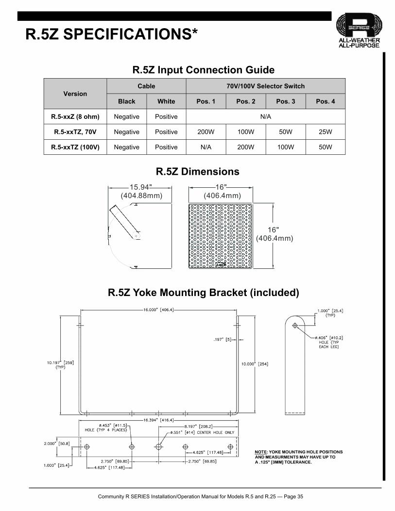
16"(406.4mm)
16"(406.4mm)
15.94"(404.88mm)
R.5Z SPECIFICATIONS*
R.5Z Input Connection Guide
R.5Z Dimensions
R.5Z Yoke Mounting Bracket (included)
Cable 70V/100V Selector Switch
Black White Pos. 1 Pos. 2 Pos. 3 Pos. 4
R.5-xxZ (8 ohm) Negative Positive N/A
R.5-xxTZ, 70V Negative Positive 200W 100W 50W 25W
R.5-xxTZ (100V) Negative Positive N/A 200W 100W 50W
Version
Community R SERIES Installation/Operation Manual for Models R.5 and R.25 — Page 36
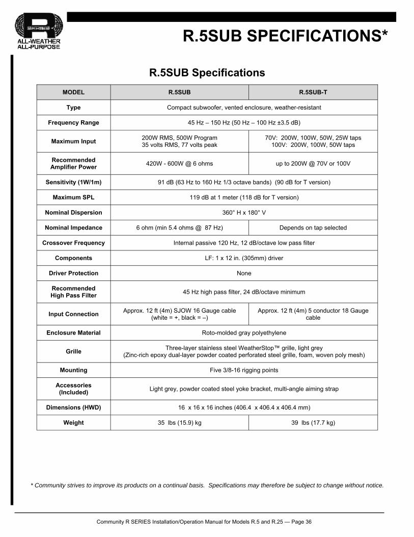
MODEL R.5SUB R.5SUB-T
Type Compact subwoofer, vented enclosure, weather-resistant
Frequency Range 45 Hz – 150 Hz (50 Hz – 100 Hz ±3.5 dB)
Maximum Input 200W RMS, 500W Program 35 volts RMS, 77 volts peak
70V: 200W, 100W, 50W, 25W taps 100V: 200W, 100W, 50W taps
Recommended Amplifier Power
420W - 600W @ 6 ohms up to 200W @ 70V or 100V
Sensitivity (1W/1m) 91 dB (63 Hz to 160 Hz 1/3 octave bands) (90 dB for T version)
Maximum SPL 119 dB at 1 meter (118 dB for T version)
Nominal Dispersion
Nominal Impedance 6 ohm (min 5.4 ohms @ 87 Hz) Depends on tap selected
Crossover Frequency Internal passive 120 Hz, 12 dB/octave low pass filter
Components LF: 1 x 12 in. (305mm) driver
Driver Protection None
Recommended High Pass Filter
45 Hz high pass filter, 24 dB/octave minimum
Input Connection Approx. 12 ft (4m) SJOW 16 Gauge cable
(white = +, black = –) Approx. 12 ft (4m) 5 conductor 18 Gauge
cable
Enclosure Material Roto-molded gray polyethylene
Grille Three-layer stainless steel WeatherStop™ grille, light grey
(Zinc-rich epoxy dual-layer powder coated perforated steel grille, foam, woven poly mesh)
Mounting Five 3/8-16 rigging points
Accessories (Included)
Light grey, powder coated steel yoke bracket, multi-angle aiming strap
Dimensions (HWD) 16 x 16 x 16 inches (406.4 x 406.4 x 406.4 mm)
Weight 35 lbs (15.9) kg 39 lbs (17.7 kg)
360° H x 180° V
R.5SUB SPECIFICATIONS*
R.5SUB Specifications
* Community strives to improve its products on a continual basis. Specifications may therefore be subject to change without notice.
Community R SERIES Installation/Operation Manual for Models R.5 and R.25 — Page 37
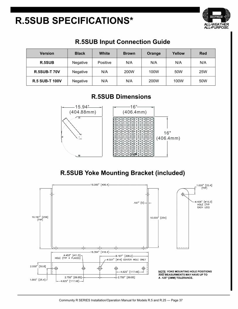
Version Black White Brown Orange Yellow Red
R.5SUB Negative Positive N/A N/A N/A N/A
R.5SUB-T 70V Negative N/A 200W 100W 50W 25W
R.5 SUB-T 100V Negative N/A N/A 200W 100W 50W
16"(406.4mm)
16"(406.4mm)
15.94"(404.88mm)
R.5SUB SPECIFICATIONS*
R.5SUB Input Connection Guide
R.5SUB Dimensions
R.5SUB Yoke Mounting Bracket (included)
Community R SERIES Installation/Operation Manual for Models R.5 and R.25 — Page 38
WARRANTY AND SERVICE
FIELD SERVICE
Any driver or crossover service required is done from the front of the enclosure by removing the screws around the edge of the grille. For warranty repair, contact Community directly or ask us for the location of your nearest Author-ized Service Center.
TRANSFERABLE WARRANTY " (L IMITED)” VALID IN THE USA ONLY
Community loudspeaker systems are warranted in the USA to be free from defects in materials and workman-ship for a period of five years, as determined by one of the following two methods, whichever is longer:
Starting from the date of retail purchase, as noted on the sales receipt from an authorized Community dealer, OR Starting from the date of manufacture, determined by the serial number, if the sales receipt is not available.
This warranty applies to the product; therefore, the remainder of the warranty period will be automatically trans-ferred to any subsequent owner. This warranty applies only to failure of a Community loudspeaker caused by defects in materials and workman-ship during the stated warranty period. It does not apply to a unit that has been subjected to abuse, accident, modification, improper handling/installation, or repairs made without factory authorization or by anyone other than authorized Community Field Service Stations. This warranty is void if the serial number has been defaced, altered or removed. Products covered by this warranty will be repaired or replaced at the option of Community, without charge for materials or labor, provided all the terms of this warranty have been met. For complete warranty information please visit our website at www.communitypro.com/warranty
OBTAINING WARRANTY SERVICE Warranty service may be obtained from the factory, or from an authorized Field Service Station. To obtain factory or field warranty service for products purchased in the United States, return the product for in-spection to the address below, freight prepaid, in the original packaging. If the original packaging is not availa-ble, call or write Community Warranty Service to obtain proper packaging materials or hand carry the product to the nearest Field Service Station.
Factory Service Center: Community Warranty Service 333 East Fifth Street Chester, PA 19013-4511 USA Field Service Station: Call (610) 876-3400 for the nearest Authorized Field Service Station
Community R SERIES Installation/Operation Manual for Models R.5 and R.25 — Page 39
WARRANTY AND SERVICE
For factory service, please call (610) 876-3400 for a Return Authorization (R/A) number before shipping. The following information must be included in the package:
Owner’s complete name, daytime phone number, return street address and return authorization number. The serial number of the product being returned and a copy of the retail sales receipt, if possible. A complete description of the problem(s) experienced, including a brief description of how the equipment is be-ing used and with what brand, model and output power of amplifier.
Upon receipt, the service center will determine if the problem is covered under warranty. If covered under this warranty, the product will be repaired or replaced, at Community’s option, and returned to the owner freight prepaid. If the problem is not covered under this warranty, the owner will be notified of the problem with an estimate of the repair costs. Consequential and Incidental Damages: Community shall not be liable for any consequential or incidental damages in-cluding, without limitation, injury to persons, property, or loss of use. Some states do not allow the exclusion or limita-tions of consequential or incidental damages, so the above limitations and exclusions may not apply. This Community warranty is not extended by the length of time which an owner is deprived of the use of the product. Repairs and replacement parts provided under the terms of this warranty shall carry only the remaining portion of the warranty. Community reserves the right to change the design of any product from time to time, without notice and with no obliga-tion to make corresponding changes in products previously manufactured. While this warranty gives specific legal rights, there may also be other rights that vary from state to state. No action to enforce this warranty shall be permitted ninety days after expiration of the warranty period.
WARRANTY INFORMATION AND SERVICE FOR COUNTRIES OTHER THAN THE USA
To obtain specific warranty information, visit the website at www.communitypro.com/warranty.To obtain available service locations for countries other than the United States of America, contact the authorized Community Distributor for your specific country or region. This warranty applies only to failure of a Community loudspeaker caused by defects in materials and workmanship dur-ing the stated warranty period. It does not apply to a unit that has been subjected to abuse, accident, modification, im-proper handling/installation, or repairs made without factory authorization or by anyone other than authorized Community Field Service Stations. This warranty is void if the serial number has been defaced, altered or removed.

Community Professional Loudspeakers 333 East Fifth Street, Chester, PA 19013-4511 USA Phone: +1 610 876-3400 Fax: +1 610 874-0190 www.communitypro.com © 2015 All Rights Reserved
# 110267 rev.02MAR2015


![INVISIBLE LOUDSPEAKER PRODUCT BROCHURE · Amina Invisible Loudspeakers [not suitable for installation of Edge Series loudspeakers]. Datasheet Mounting Blocks For use when there is](https://img.dokumen.tips/doc/110x75/5e4171904930695cb670153f/invisible-loudspeaker-product-amina-invisible-loudspeakers-not-suitable-for-installation.jpg)